
WWW.JAMRIS.ORG pISSN 1897-8649 (PRINT)/eISSN 2080-2145 (ONLINE) VOLUME 17, N° 4, 2023
Indexed in SCOPUS


WWW.JAMRIS.ORG pISSN 1897-8649 (PRINT)/eISSN 2080-2145 (ONLINE) VOLUME 17, N° 4, 2023
Indexed in SCOPUS


A peer-reviewed quarterly focusing on new achievements in the following fields:
• automation • systems and control • autonomous systems • multiagent systems • decision-making and decision support • • robotics • mechatronics • data sciences • new computing paradigms •
Editor-in-Chief
Janusz Kacprzyk (Polish Academy of Sciences, Łukasiewicz-PIAP, Poland)
Advisory Board
Dimitar Filev (Research & Advenced Engineering, Ford Motor Company, USA)
Kaoru Hirota (Tokyo Institute of Technology, Japan)
Witold Pedrycz (ECERF, University of Alberta, Canada)
Co-Editors
Roman Szewczyk (Łukasiewicz-PIAP, Warsaw University of Technology, Poland)
Oscar Castillo (Tijuana Institute of Technology, Mexico)
Marek Zaremba (University of Quebec, Canada)
Executive Editor
Katarzyna Rzeplinska-Rykała, e-mail: office@jamris.org (Łukasiewicz-PIAP, Poland)
Associate Editor
Piotr Skrzypczyński (Poznań University of Technology, Poland)
Statistical Editor
Małgorzata Kaliczyńska (Łukasiewicz-PIAP, Poland)
Typesetting
SCIENDO, www.sciendo.com
Webmaster
TOMP, www.tomp.pl
Editorial Office
ŁUKASIEWICZ Research Network
– Industrial Research Institute for Automation and Measurements PIAP
Al. Jerozolimskie 202, 02-486 Warsaw, Poland (www.jamris.org) tel. +48-22-8740109, e-mail: office@jamris.org
The reference version of the journal is e-version. Printed in 100 copies.
Articles are reviewed, excluding advertisements and descriptions of products.
Papers published currently are available for non-commercial use under the Creative Commons Attribution-NonCommercial-NoDerivs 4.0 (CC BY-NC-ND 4.0) license. Details are available at: https://www.jamris.org/index.php/JAMRIS/
LicenseToPublish
Editorial Board:
Chairman – Janusz Kacprzyk (Polish Academy of Sciences, Łukasiewicz-PIAP, Poland)
Plamen Angelov (Lancaster University, UK)
Adam Borkowski (Polish Academy of Sciences, Poland)
Wolfgang Borutzky (Fachhochschule Bonn-Rhein-Sieg, Germany)
Bice Cavallo (University of Naples Federico II, Italy)
Chin Chen Chang (Feng Chia University, Taiwan)
Jorge Manuel Miranda Dias (University of Coimbra, Portugal)
Andries Engelbrecht ( University of Stellenbosch, Republic of South Africa)
Pablo Estévez (University of Chile)
Bogdan Gabrys (Bournemouth University, UK)
Fernando Gomide (University of Campinas, Brazil)
Aboul Ella Hassanien (Cairo University, Egypt)
Joachim Hertzberg (Osnabrück University, Germany)
Tadeusz Kaczorek (Białystok University of Technology, Poland)
Nikola Kasabov (Auckland University of Technology, New Zealand)
Marian P. Kaźmierkowski (Warsaw University of Technology, Poland)
Laszlo T. Kóczy (Szechenyi Istvan University, Gyor and Budapest University of Technology and Economics, Hungary)
Józef Korbicz (University of Zielona Góra, Poland)
Eckart Kramer (Fachhochschule Eberswalde, Germany)
Rudolf Kruse (Otto-von-Guericke-Universität, Germany)
Ching-Teng Lin (National Chiao-Tung University, Taiwan)
Piotr Kulczycki (AGH University of Science and Technology, Poland)
Andrew Kusiak (University of Iowa, USA)
Mark Last (Ben-Gurion University, Israel)
Anthony Maciejewski (Colorado State University, USA)
Copyright
Krzysztof Malinowski (Warsaw University of Technology, Poland)
Andrzej Masłowski (Warsaw University of Technology, Poland)
Patricia Melin (Tijuana Institute of Technology, Mexico)
Fazel Naghdy (University of Wollongong, Australia)
Zbigniew Nahorski (Polish Academy of Sciences, Poland)
Nadia Nedjah (State University of Rio de Janeiro, Brazil)
Dmitry A. Novikov (Institute of Control Sciences, Russian Academy of Sciences, Russia)
Duc Truong Pham (Birmingham University, UK)
Lech Polkowski (University of Warmia and Mazury, Poland)
Alain Pruski (University of Metz, France)
Rita Ribeiro (UNINOVA, Instituto de Desenvolvimento de Novas Tecnologias, Portugal)
Imre Rudas (Óbuda University, Hungary)
Leszek Rutkowski (Czestochowa University of Technology, Poland)
Alessandro Saffiotti (Örebro University, Sweden)
Klaus Schilling (Julius-Maximilians-University Wuerzburg, Germany)
Vassil Sgurev (Bulgarian Academy of Sciences, Department of Intelligent Systems, Bulgaria)
Helena Szczerbicka (Leibniz Universität, Germany)
Ryszard Tadeusiewicz (AGH University of Science and Technology, Poland)
Stanisław Tarasiewicz (University of Laval, Canada)
Piotr Tatjewski (Warsaw University of Technology, Poland)
Rene Wamkeue (University of Quebec, Canada)
Janusz Zalewski (Florida Gulf Coast University, USA)
Teresa Zielińska (Warsaw University of Technology, Poland)
Publisher: All rights reserved

VOLUME 17, N˚4, 2023
DOI: 10.14313/JAMRIS/4-2023
1
Matrix Transposition Algorithm Using Cache Oblivious
Samuel Guzmán López, Adolfo Javier San Gil Santana, Jorge Alberto Cuba Alonso del Rivero, Sonia Pérez Lovelle, Humberto Díaz Pando
DOI: 10.14313/JAMRIS/4‐2023/25
8
On Various Types of Soft Ground – A Case Study on Various Types of Soft Ground – A Case Study
Maciej Trojnacki, Przemysław Dąbek
DOI: 10.14313/JAMRIS/4‐2023/26
17
The Overview of Challenges in Detecting Patients’ Hazards During Robot‐Aided Remote Home Motor Rehabilitation
Julia Wilk, Piotr Falkowski, Tomasz Osiak
DOI: 10.14313/JAMRIS/4‐2023/27
28
Binary Shuffled Frog Leaping Algorithm for Optimal Allocation of Power Quality Monitors in Unbalanced Distribution System
Ashkan Doust Mohammadi, Mohammad Mohammadi
DOI: 10.14313/JAMRIS/4‐2023/28
40
Lyapunov‐L Lasalle Based Dynamic Stabilization for Fixed Wing Drones
Jean Sawma, Alain Ajami, Thibault Maillot, Joseph el Maalouf
Doi: 10.14313/JAMRIS/4‐2023/29
49
New Robust Model for Stability and H∞ Analysis for Interconnected Embedded Systems
Amal Zouhri
DOI: 10.14313/JAMRIS/4‐2023/30
56
Wimax Network Optimization Using Frame Period with Channel Allocation Techniques
Mubeen Ahmed Khan, Awanit Kumar, Kailash Chandra Bandhu
DOI: 10.14313/JAMRIS/4‐2023/31
68
Extended State Observer Based Robust Feedback Linearization Control Applied to an Industrial CSTR
Ali Medjebouri
DOI: 10.14313/JAMRIS/4‐2023/32
79
Implementing Visual Assistant Using YOLO and SSD for Visually‐Impaired Persons
Ratnesh Litoriya, Kailash Chandra Bandhu, Sanket Gupta, Ishika Rajawat, Hany Jagwa
DOI: 10.14313/JAMRIS/4‐2023/33
Submitted:11th January2023;accepted:18th March2023
DOI:10.14313/JAMRIS/4‐2023/25
Abstract:
TheParallelandDistributedComputinggroupbelonging totheIntegratedTechnologicalResearchComplex(CITI). hasbeenengagedinthecreationofgeneral‐purpose componentsthatsupporttheprocessingoflargevolumes ofinformationthatcharacterizetheproblemsinvolvedin parallelcomputing.
Usingtheobliviouscachemodel,whichworksinde‐pendentlyofthecomputerarchitecture,andthedivide andconquerprinciple,analgorithmformatrixtrans‐positionisimplementedtoreducetheexecutiontime ofthisalgebraicoperation.Thealgorithmensuresthat mostofthedatacontentisloadedtothecacheforfast processing,andmakesthemostofitsstayinthecache tominimizemissedreadsandachievegreaterspeed.
Theworkincludesconclusionsandstatisticaltests carriedoutfromexperimentsoncomputerswithdifferent architectures,reflectingthesuperiorityofthealgorithm thatusesobliviouscachefromanorderofmatrixdeter‐minedaccordingtothecharacteristicsofeachPC.
Keywords: Cacheoblivious,Matrixtransposition,Missed readings
TheIntegratedTechnologicalResearchComplex (CITI)wascreatedasacoordinationprojectbetween the TechnologicalUniversityofHavana(CUJAE)and theMinistryofInterior(MININT).Thisentityis designedtohostthemostadvancedtechnologies beingworkedwithworldwide[1].
CITI’smissionistodeveloptechnologiesto enhancethesecurityandinternalorderofthe country.Itsvisionistobeacreative,innovative andbenchmarkorganizationinhumancapital management.Inaddition,tobeareferencein theapplicabilityoftheresultsobtainedinthe developmentofsystems,technologiesandinnovative integratedapplications,withimpactonsecurityand internalorder,forwhichitwillbaseitsworkonthe integrationofhighlyquali iedprofessionalswith talentedstudents[1].
AtCITIthereareprojectsinwhichmatrixtranspo‐sitionisintensivelyused,sothistaskwasassignedto theParallelandDistributedComputinggroup,which isdedicatedtoreducetheexecutiontimeofvari‐ousalgorithmsbyemployingparallelismandrecur‐rencetechniques.Thistime,thetechniqueselectedby thegroupwasthecacheoblivious,arecurrenttech‐niqueaboutwhichthereissomeliteratureandimple‐mentationtestedanddocumentedbyotherauthors [2–4].Thismethodwasusedbytheauthorsina researchworkonmatrixmultiplicationobtaining goodresults[5].
Cache‐awarealgorithmstakeintoaccountthe hardwarearchitectureonwhichtheyarerunning, mainlythecachearchitecture,i.e.thenumberofcache levelsandthesizeofeachlevel.Theyarespeci ically developedtoperformaswellaspossibleintheenvi‐ronmentforwhichtheywerecreated.
Thisposesaproblemwhenchangingtheenviron‐ment,sinceifacache‐awarealgorithmisexecuted outsidethearchitectureforwhichitwasdesigned, itwillnotperformwell.Tocounteractthisproblem, cacheobliviousalgorithmswerecreated,ablework ef icientlyonanyarchitecture[6].
Cacheobliviousalgorithmshaveadesignthatwill alwaysbe“cache‐optimal”,regardlessofthecache hierarchy.In1996,theideaofrealizingalgorithms thatdonottakeintoaccountthearchitectureofthe computerwheretheyareexecutedwasconceivedby CharlesE.Leisersonandcalledcacheobliviousalgo‐rithms.Thistopicwas irstpublishedin1999byHar‐aldProkopinhismaster’sthesisattheMassachusetts InstituteofTechnology[4].Theuseofthecache obliviousmodelhasawidevarietyofapplications suchas:matrixmultiplication,matrixtransposition, Bioinformatics(RNAsecondarystructureprediction), ShortestPathAlgorithmwithorderO(n),dynamic programmingoftheGaussiansolution(Numerical Mathematics).
Theuseofthecacheobliviousmodelaimsto decreasemissedreadsorcachemissessincethese algorithmsusethedivide‐and‐conquerprincipleto dividetheproblemintosmallsubproblemsuntila cache‐ ittingsizeisreached,regardlessofthesizeof thecache.
Byreducingthenumberofmissedreadsorcache misses,executiontimesaresigni icantlyreduced, resultingingreateref iciency.
Oneofthefeaturesbywhichitoutperformsthe traditionalcacheisself‐tuning.Intypicalcachealgo‐rithms,thealgorithmsrequiretuningtovariouscache parametersthatarenotalwaysavailablefromthe manufacturerandareoftendif iculttoextractauto‐maticallywhichhinderscodeportabilitywhereasin cacheobliviousalgorithmsnosuchtuningisrequired, asinglealgorithmshouldworkwellonallmachines withoutanymodi ication[3,4,7–9].
Matrixtranspositionisafundamentaloperation oflinearalgebraandothercomputationalprimitives suchasthemultidimensionalFastFourierTransform; itisalsoappliedinnumericalanalysisineconomics, imageandgraphicsprocessing,aswellasbeingused incryptographicmethods[10].
Thisseeminglyinnocuouspermutationproblem lacksbothtemporalandspatiallocalityandisthere‐foredif iculttoimplementef icientlyformatriceswith alargevolumeofdata.Infact,thereisnotemporal localitytoexploit,sinceeachelementofthematrixis accessedatmostonce[10].
Asfarasspatiallocalityisconcerned,thematrix elementswaps(i,j)and(j,i)implicitinthetranspose semantics,whentranslatedintomemoryaddresses usingcanonicalrow‐majororcolumn‐majorordering, equalsthememorylocalitiesni+jandnj+i.Depending onthevaluesofiandj,thesemaybecloseorfar apartintermsofcachesetsormemorypages.Care‐fulschedulingoftheseswapoperationsisrequired togainanyadvantagefromthesemultiwordcache lines[10].
Explicittranspositionofanarrayintomemorycan oftenbeavoidedbyaccessingthesamedatainadif‐ferentorder.Forexample,softwarelibrariesforlinear algebra,suchasBLAS,generallyprovideoptionsto specifythatcertainmatricesshouldbeinterpretedin transposedordertoavoidtheneedfordatamove‐ment[10].
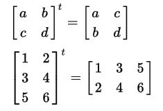
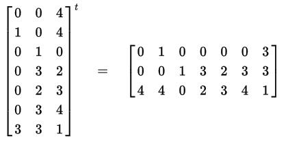
Describingthealgebraicoperationassuch,atrans‐posedmatrixistheresultofrearrangingtheorigi‐nalmatrixbyexchangingrowsforcolumnsinanew matrix(seeFigures1and2).
Inotherwords,thetransposedmatrixistheaction ofselectingrowsfromtheoriginalmatrixandrewrit‐ingthemascolumnsinthenewmatrix.
Examples:
Themanipulationofmatriceswithalargenum‐berofrowsandcolumnsinvolvesbigproblems,even whentheyarehandledwithacomputer.Therefore, itisofteninterestingtoknowhowtodecomposea problemusinglargematricesintosmallerproblems, i.e.,usingsmallermatrices[11].
Thepossibilityofdecomposingamatrixinto smallermatriceshasmanyapplicationsincommuni‐cations,electronics,solvingsystemsofequations,tak‐ingadvantageofthevectorstructureofsomecomput‐ers,andsoon.And,especially,itgivesthepossibility ofwritingamatrixinamorecompactway[11].
Theblocksareobtainedbydrawingimaginaryver‐ticalandhorizontallinesbetweentheelementsofthe matrix.Theirdimensiondependsonthesizeofthe cacheblocksandaimstostoreasmuchinformation aspossible.
Thefundamentalideaistoreducethetransposeof amatrixtothetransposeofsmallsubmatrices.Thisis achievedbydividingthematricesinahalfalongtheir largestdimensionuntilonlyonematrixtransposethat itsinthecacheneedstobecarriedout(intheory, onecouldfurtherdividethematricesdowntoabase caseofsize1×1,butinpracticealargerbasecaseis used,e.g.,16×16,inordertoamortizetheoverhead ofcallingrecursivesubroutines)[12].
Insection 2,allthetheoreticalfoundationsthat supporttheimplementationofamatrixtransposition algorithmusingthecacheobliviousmodelwerepre‐sented.Algorithm 1,adaptedfromtheonefoundin https://es.stackoverflow.com,wasused.
Thisalgorithmhasfourintegersandapointeras parameters,ofwhichthe irstandthirdarefunda‐mentaltodividetheoriginalmatrixintosmallsub‐matrices.Thesecondandfourthrefertothenumber ofrowsandcolumnsrespectively,whilethepointer referstotheresultmatrix.
Table1. Computercharacteristics
Characteristics
PC1 PC2 PC3 PC4 PC5 PC6 PC7
Processor Intel(R)Core (TM) i3‐5020UCPU @2.2GHz 2.2GHz
RAM 4,00GB
Single‐Channel DDR3 @798MHz
Intel(R) Celeron(R) CPUG3900@ 2.8GHz 2.8GHz
4.00GB
(2.95GB utilizable) DDR4‐2133
Intel(R) Celeron(R) CPUG1840@ 2.8GHz 2.8GHz
2,00GB
Single‐Channel DDR3 @665MHz
Intel(R)Core (TM) i3‐7130UCPU @2.7GHz 2.7GHz
8.00GB (7.95GB utilizable) DDR4‐2400
Intel(R)Core (TM)i3‐4130 CPU@ 3.4GHz
Intel(R)Core (TM) i7‐1165G7@ 2.8GHz 2.8GHz
8.00GBDDR3 16.2GB (15.8GB utilizable) DDR4‐3200
Intel(R) Pentium(R) CPUG4560@ 3.50GHz 3.50GHz
8.00GB (7.95GB utilizable) DDR4‐2400
Typeof system Windows64 bits Windows64 bits Windows64 bits Windows64 bits Linux64bits Windows64 bits Windows64 bits
Motherboard ASUSTek COMPUTER INC.X540LA
Gigabyte Technology Co.,Ltd. B85M‐DS3H
Gigabyte Technology Co.,Ltd. B85M‐DS3H
voidcachetranspose(int rb, int re, int cb, int ce, Matrix*T)
{int r=re-rb,c=ce-cb; if (r<= 16 &&c<= 16){ for (int i=rb;i<re;i++){ for (int j=cb;j<ce;j++){
T->data[j*rows+i]=data[i*columns+j];}}} else if (r>=c){
cachetranspose(rb,rb+(r/2),cb,ce,T); cachetranspose(rb+(r/2),re,cb,ce,T);} else {
cachetranspose(rb,re,cb,cb+(c/2),T); cachetranspose(rb,re,cb+(c/2),ce,T);}}
Algorithm1. Recursivematrixtranspositionalgorithm usingcacheoblivious
Forthedevelopmentoftheexperimentsitwas necessaryapreviousstudyofseveralalgorithms(tra‐ditional,blocksandblocks_for_squared_matrices)to establishacomparisonwiththoseusingthecache obliviousmodel(forsquareandnon‐squareorders). Theseexperimentsconsistofrunningeachalgorithm 5timesonorderswithdifferentcharacteristics(see Table1).Fromtheresultsobtained,astatisticalanaly‐sisisperformedtodeterminewhetherthealgorithms usingthecacheobliviousmodelaresuperior(interms ofexecutiontimeandmissedreads)tothosethatdo notusethismodel.
Inthissectionwepresentdiagramsshowingthe averageexecutiontimeandthemissedreadings(the latteronlyinPC5),foreachofthealgorithmsanalyzed.
Inthosecases,wherenon‐squaredmatriceswere tested,thesewere illedwithzerosinordertousethe blocks_for_squared_matricesalgorithmforthecorre‐spondingcomparisons.
DellInc. 02DG7R (U3E1)
VersiónA00
Gigabyte B85M‐DS3H HPSpectre 14‐EA GigabyteGa‐H110m‐S2h
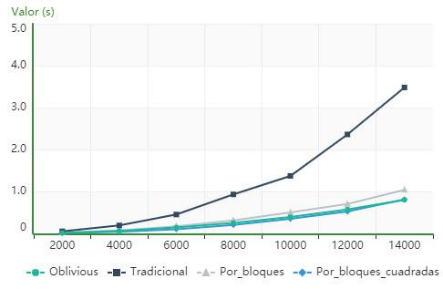
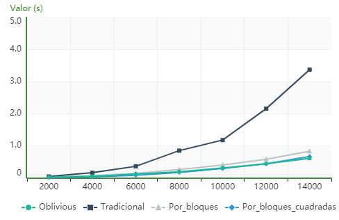
AscanbeseeninFigure3,forthecomputeriden‐ti iedasPC1,theblocks_for_squared_matricesalgo‐rithmisfasterthantherestofthoseanalyzedfor orderslowerthan14000,fromwhichthealgorithm usingcacheobliviousstartstobesuperior.
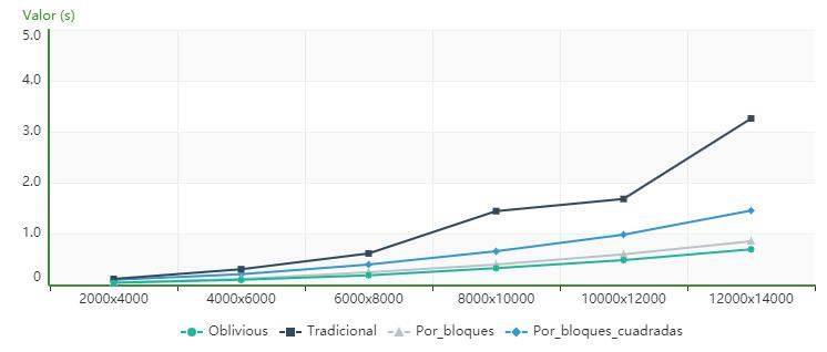
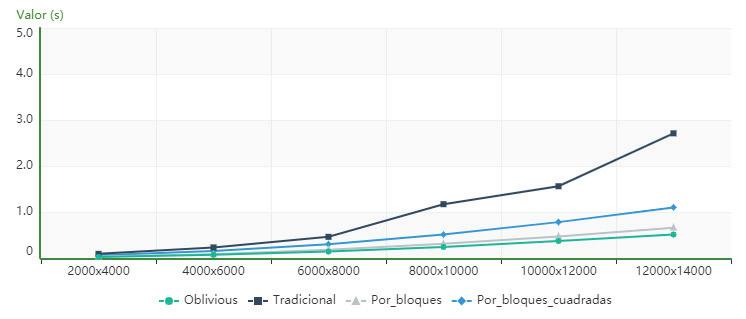
Figure4showsthatforthecomputeridenti iedas PC1,thealgorithmusingcacheobliviousissuperior intermsofexecutiontimetothetraditional,block andblock_for_squared_matricesalgorithmsforallthe ordersanalyzed.

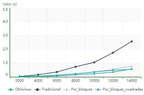
ItisevidentfromFigure5 that,forthecomputer describedasPC2,thealgorithmusingcacheoblivious issuperiorintermsofexecutiontimetothetradi‐tionalandblockalgorithmsforallorders,whilethe blocks_for_squared_matricesalgorithmhasloweror similartimestotheoneusingcacheobliviousupto order10000,fromwhichthecacheobliviousalgo‐rithmpresentslowervalues.
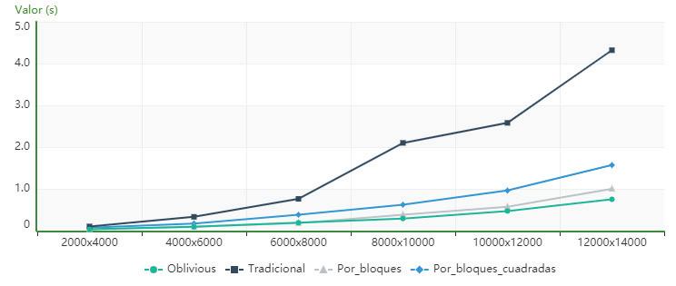
Figure6showsthat,forthecomputeridenti iedas PC2,thealgorithmusingcacheobliviousissuperior intermsofexecutiontimetothetraditional,block andblock_for_squared_matricesalgorithmsforallthe ordersanalyzed.
Figure 7 showsthat,forthecomputeridenti‐iedasPC3,thealgorithmusingcacheobliviousis superiorintermsofexecutiontimetothetradi‐tionalandblockalgorithmsforallorders,whilethe blocks_for_squared_matricesalgorithmhaslowerexe‐cutiontimesthantheoneusingcacheobliviousup toorder6000.Between8000and12000theresults aresimilarandfromthelatter,thecacheoblivious algorithmstartstohavelowervalues.
Figure8showsthat,forthecomputeridenti iedas PC3,thealgorithmusingcacheobliviousissuperior intermsofexecutiontimetothetraditional,block andblock_for_squared_matricesalgorithmsforallthe ordersanalyzed.
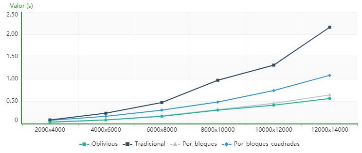
non‐squareorders
Figure 9 showsthat,forthecomputeridenti‐iedasPC4,thealgorithmusingcacheobliviousis superiorintermsofexecutiontimetothetradi‐tionalandblockalgorithmsforallorders,whilethe blocks_for_squared_matricesalgorithmhaslowerexe‐cutiontimesthantheoneusingcacheobliviousuntil order12000,whentheystarttohavesimilarvalues.
Figure10showsthat,forthecomputeridenti ied asPC4,thealgorithmusingcacheobliviousissuperior intermsofexecutiontimetothetraditional,block andblock_for_square_matricesalgorithmsforallthe ordersanalyzed.
Figure11showsthat,forthecomputeridenti ied asPC5,thealgorithmusingcacheobliviousissuperior intermsofexecutiontimetothetraditional,block andblock_for_squared_matricesalgorithmsforallthe ordersanalyzed.
Figure12showsthat,forthecomputeridenti ied asPC5,thealgorithmusingcacheobliviousissuperior intermsofexecutiontimetothetraditional,block andblock_for_squared_matricesalgorithmsforallthe ordersanalyzed.
ItisevidentinFigure 13 that,forthecomputer identi iedasPC6,thealgorithmusingcache
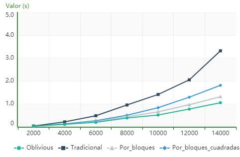
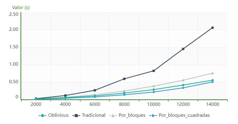
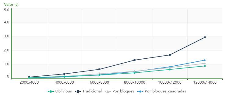
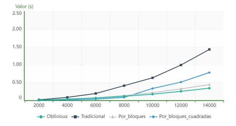
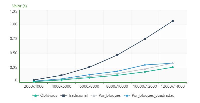
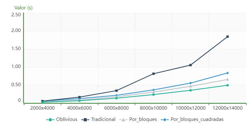
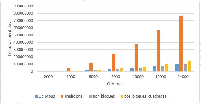
Figure17. Performanceofthealgorithmsintermsof missedreadingsonPC5forsquareorders
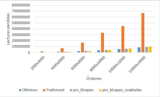
Figure18. Performanceofthealgorithmsintermsof missedreadingsonPC5fornon‐squareorders
obliviousissuperiorintermsofexecutiontime tothetraditionalalgorithms,byblocksand blocks_for_squared_matrices,startingfromthe order10000x10000.
Figure14showsthat,forthecomputeridenti ied asPC6,thealgorithmusingcacheobliviousissuperior intermsofexecutiontimetothetraditional,block
andblock_for_squared_matricesalgorithmsforallthe ordersanalyzed.
Figure15showsthat,forthecomputeridenti ied asPC7,theblocks_for_squared_matricesalgorithmis superiortotheothersanalyzedanditcanbeobserved thatthealgorithmusingcacheobliviousobtainsa certainparityfromtheorder14000x14000.
Table2. ResultsobtainedinPC1forsquareorders
Algorithms traditional blocks blocks_for_squared_matrices
Table3. ResultsobtainedinPC1fornon‐squaredorders
Algorithms traditional blocks blocks_for_squared_matrices
Table4. ResultsobtainedinPC5formissedreadingsinsquareorders
Algorithms traditional blocks blocks_for_squared_matrices
Table5. ResultsobtainedinPC5formissingreadingsinnon‐squareorders
Algorithms traditional blocks blocks_for_squared_matrices
Figure16showsthat,forthecomputeridenti ied asPC7,thealgorithmusingcacheobliviousissuperior intermsofexecutiontimetothetraditional,block andblock_for_squared_matricesalgorithmsforallthe ordersanalyzed.
4.1.1.Missedreadings
ThePAPI(PerformanceApplicationProgramming Interface)library,developedattheUniversityofTen‐nessee,wasusedtoaccountformissedreads.Itsmain purposeistoprovideaccesstothePMCs(Perfor‐manceMonitoringCounter)ofadiversecollectionof modernprocessors[13].PAPIprovidesanabstraction layerthatallowsdeveloperstoaccessPMCs.Instead, thedeveloperusescallstothePAPIAPI(Application ProgramingInterface),makingthecodeportable,i.e. itcanbeusedonanyarchitecturesupportedbythe librarywithoutmodifyingaccesstoPMCs[14].
ThemissingreadingswerecountedonthePC5 computer,whichhasaLinuxoperatingsystem becausethelibraryused(PAPI)hasnotprovidednew updatessincetheXPversionofWindows.
Figure17showsthat,forthecomputeridenti ied asPC5,thealgorithmthatusescacheoblivioushasthe lowestnumberofmissedreadings.
Figure18showsthat,forthecomputeridenti ied asPC5,thealgorithmusingcacheoblivioushasfewer missedreadings.
TheWilcoxonnonparametrictestwasusedforsta‐tisticalanalysis.Itwasselectedsinceitwasproven thatthedatadonotfollowanormaldistributionand duetothesmallsamplesize.Itisexpectedthat,when thetestisrun,itwillreturnap<∝value,ifthisoccurs H0 isrejectedanditisconcludedthattheexecution timeofthecacheobliviousalgorithmislessthanthat ofthetraditionalalgorithm.
Severalsignedranktestswereappliedwhenthe sampleswerepaired,oneforeachofthelastthree ordersofthealgorithmsoneachcomputerdescribed.
ThefollowingaretheresultsobtainedonPC1in termsofexecutiontimeandonPC5intermsofmissed readings:
ItisevidentintheresultsofTable 2 thatthe blocks_for_squared_matricesalgorithmisfasterthan therestoftheanalyzedalgorithmsfororderslower than14000,fromwhichthealgorithmusingcache obliviousstartstobesuperior.
TheresultsinTable 3 showthesuperiorityin termsofexecutiontimeofthealgorithmusingthe cacheobliviousmodelforalltheordersanalyzed.
Table 4 showsthesuperiorityintermsofmissed readingsofthealgorithmusingthecacheoblivious modelforallordersanalyzed.
Table 5 showsthesuperiorityintermsofmissed readingsofthealgorithmusingthecacheoblivious modelforallordersanalyzed.
Thetestwasperformedwiththestatisticalsoft‐wareR.Afterthetestitwasdemonstratedthatthe matrixtranspositionalgorithmusingthecacheobliv‐ious,dependingonthearchitectureofthecomputer whereitwasusedandfromacertainorder,willbe betterthantheotheralgorithmsanalyzed.
Underthecomputationalconditionsusedforthe experiments:
1) OnacomputerwithaWindowsoperatingsystem, inthematrixtranspositionoperation,forsquare ordermatricesitisnotfeasibletoemploythealgo‐rithmusingthecacheobliviousmodelforanorder lessthan14000x14000.
2) Regardlessofthecomputerarchitecture,itwas shownthatfromorder6000x8000fornon‐square ordermatrices,thematrixtranspositionalgorithm usingcacheobliviousisfasterthantherestofthe algorithmsstudied.
3) Theblocks_for_squared_matricesalgorithmhasa lowerperformancewhenusedfornon‐square matricessincethesemustbecompletedwithzeros untiltheirorderissquareandthereforethealgo‐rithmincreasesitsexecutiontime.
4) Forlargevolumesofinformation,theexecution timeisindirectcorrespondencetothemissed readings.
5) Algorithmsthatusethecacheobliviousmodelfor largevolumesofinformationhavefewermissed readingsthantherest.
SamuelGuzmánLópez∗ –TechnologicalUniversity ofHavanaJoséAntonioEcheverría,Cuba,e‐mail: samuguzmanlopez97@gmail.com.
AdolfoJavierSanGilSantana –TechnologicalUni‐versityofHavanaJoséAntonioEcheverría,Cuba, e‐mail:asang@ceis.cujae.edu.cu.
JorgeAlbertoCubaAlonsodelRivero –Techno‐logicalUniversityofHavanaJoséAntonioEcheverría, Cuba,e‐mail:jcuba@ceis.cujae.edu.cu.
SoniaPérezLovelle –TechnologicalUniversity ofHavanaJoséAntonioEcheverría,Cuba,e‐mail: sperezl@ceis.cujae.edu.cu.
HumbertoDíazPando –TechnologicalUniversityof HavanaJoséAntonioEcheverría,Cuba,e‐mail:hdi‐azp@ceis.cujae.edu.cu.
∗Correspondingauthor
[1] www.portal.citi.cu.(accessed4/6/2019).
[2] C.Mayer.“Cacheobliviousmatrixoperations usingPeanocurves,”DepartmentofComputer ScienceTechnischeUniversityMunchen,Ger‐many,2006.
[3] M.Frigo,Leiserson,H.Prokop,andRamachan‐dran.“CacheObliviousAlgorithms”,MITLabo‐ratoryforComputerScience,Cambridge,USA, 1999.
[4] H.Prokop.“Cache‐ObliviousAlgorithms,” DepartmentofElectricalEngineeringand ComputerScience,MassachusettsInstituteof Technology.,Massachusetts1999.
[5] A.J.SanGilSantana,S.GuzmánLópez,andJ. A.CubaAlonsodelRivero.“Algoritmodemul‐tiplicacióndematricesutilizandocach incon‐scienteycurvadePeano,” XVIIIConvencióny FeriainternacionalInformática2020, 2020.
[6] T.M.Chilimbi.“CacheConsciousDataStructues DesingandImplementation,”UniversityOfWis‐consin1999.
[7] M.Frigo,C.E.Leiserson,H.Prokop,andS. Ramachandran.“Cache‐ObliviousAlgorithms,” ACMTransactionsonAlgorithms, 2012.
[8] Ritika.“Cache‐awareandcache‐obliviousalgo‐rithms,”MasterofEngineeringComputersci‐enceandengineering,ThaparUniversityPatiala 2011.
[9] S.NeerajandS.Sandeeep.“E?cientcacheobliv‐iousalgorithmsforrandomizeddivide‐and‐conqueronthemulticoremodel,”2018.
[10] S.ChatterjeeandS.Sen.“CacheEf icientMatrix Transposition,”DepartmentofComputerSci‐ense,UniversityofNorthCarolinaChapelHill,NC 27599‐3175,USA–IndianInstituteofTechnol‐ogyNewDelhi110016,India,2005.
[11] M.Palacios.“Matrices,”Departamentode MatemáticaAplicadaUniversidaddeZaragoza, 2018.
[12] D.Tsifakis,P.Alistair,Rendell,andP.E.Strazdins. “CacheObliviousMatrixTransposition:Simu‐lationandExperiment,”DepartmentofCom‐puterScience,AustralianNationalUniversity Canberra,Australian,2004.
[13] V.M.Weaveretal..“PAPI5:MeasuringPower, EnergyandtheCloud,” International-Symposium onPerformaceAnalysisofSystemsandSoftware, 2013.
[14] P.J.Mucci,S.Browne,C.Deane,andG.HO.“PAPI: APortableInterfacetoHadwarePerformance Counters,”UniversityofTennessee,Knoxville, Tennessee,1999.
Submitted:13th October2023;accepted:27th November2023
DOI:10.14313/JAMRIS/4‐2023/26
Abstract:
Aproblemofinfluenceofthreetypesofsoftground onlongitudinalmotionofalightweightfour‐wheeled mobilerobotisconsidered.Kinematicstructure,main designfeaturesoftherobotanditsdynamicsmodel aredescribed.Anumericalmodelwaselaboratedto simulatethedynamicsoftherobot’smulti‐bodysystem andthewheel‐groundinteraction,takingintoaccount thesoildeformationandstressesoccurringonthecir‐cumferenceofthewheelintheareaofcontactwith thedeformableground.Numericalanalysisinvolvingfour velocitiesofrobotmotionandthreecasesofsoil(dry sand,sandyloam,clayeysoil)isperformed.Withinsim‐ulationresearch,themotionparametersoftherobot, groundreactionforcesandmomentsofforce,driving torques,wheelsinkageandslipparametersofwheels werecalculated.Aggregatedresearchresultsaswellas detailedresultsofselectedsimulationsareshownand discussed.Asaresultoftheresearch,itwasnoticed thatwheelslipratios,wheels’sinkageandwheeldriving torquesincreasewithdesiredvelocityofmotion.More‐over,itwasobservedthatwheels’sinkageanddriving torquesaresignificantlylargerfordrysandthanforthe otherinvestigatedgroundtypes.
Keywords: Lightweightwheeledmobilerobot,Longitudi‐nalmotion,Deformableground,Dynamicsmodel,Tire‐groundinteraction,Wheelslip,Wheelsinkage,Simula‐tionstudies
Lightweightwheeledmobilerobotsareversatile vehiclesthatworkinbothindoorandoutdoorenvi‐ronments.Thelargestgroupofsuchvehiclesare lightweightmobilerobots,anexampleofwhichare robotsforspecialapplications.Suchrobotsmoveon avarietyofsurfaces,bothpaved[1]andunpaved[2].
Atthestageofdesigningrobotstructuresand controlsystems,itisbene icialtoknowtherobot dynamicsmodel[3,4].Theformoftherobotdynamics modelisfundamentallyin luencedbyitskinematic structure[5],whichdependsontheareaofapplication oftherobot.Suchamodelcanbedevelopedusingclas‐sicalmethods,e.g.,usingtheNewton‐Eulerformalism orLagrangeformalism[6].
Alternativemethodsmayalsobeusedinwhichthe dynamicsmodelcanbebuiltusingsystemidenti ica‐tionthroughmeasurementsoftheinputandoutput signalsofthesystem[7].Thisprocesscanbecar‐riedoutbothof line[8]andonline,dependingonthe method.Italsomayormaynotrequiretheknowledge oftherobot’smodelstructure.Arti icialintelligence methodscanalsobeused[9],e.g.,basedonarti icial neuralnetworks[10],toapproximateunknownnon‐linearfunctionsinthedynamicsmodel.
Regardlessoftheadoptedmethodofcreating thedynamicsmodel,itisimportantthatittakes intoaccountthewheel‐groundinteraction.Forthis purpose,tiremodelsareintroducedinthedynam‐icsmodel.Tire‐groundinteractioninthecaseof lightweightmobilerobotsmovingatrelativelyhigh speedsshouldtakeintoaccountthepossibilityof wheelslippage.Ifrobotmotionoccursondeformable ground,theninadditiontowheelsliptheground deformationhastobeconsideredaswell.Modeling theinteractionofwheelswithunpavedgroundisthe subjectofterramechanics,thebasisofwhichwasfor‐mulatedinthework[11].
Theproblemofmotionondeformablegroundis ofcriticalimportanceinthecaseofoutdoorwheeled mobilerobotsusedforreconnaissanceincivilandmil‐itaryscenariosandisrelatedtotheproblemofrobot mobility.Inthiscase,thequestionsofhowtheground typeanddesiredrobotvelocityaffectwheelslips,soil deformation(orwheelsinkage)anddrivingtorques shouldbeanswered.Examplesofstudiesofmotion ofvehiclesondeformablegrounds,especiallytracked andwheeledones,are[11,12]and[13].Themajority ofworksisfocusedonmannedvehicles;however, onecanalso indworksconcerningwheeledmobile robots,forinstance[14],andinparticularplanetary rovers[15,16].Heavyoff‐roadvehiclestypicallyuse pneumaticwheels.Apartfromthetread,theirdriving propertiesaredeterminedbytirepressure,aswellas wheeldiameterandwidth.Theresearchresultsinthis areaaredescribed,amongothers,inworks[11,12]. Inturn,lightweightvehicles,suchasmobilerobots forspecialapplicationsoftenhavenon‐pneumatic wheels.Therefore,intheircase,themechanicalprop‐ertiesofthewheel illingsusedareimportant.
Theaimofthispaperistostudythein luence ofthreetypesofdeformablegroundonthemotion parametersofalightweightwheeledmobilerobot duringitslongitudinalmotion.Theanalysisiscar‐riedoutfortherobotmovingwithvariousdesired velocitiesonthreedifferenttypesofsoftground,i.e., drysand,sandyloamandclayeysoil.Inthepresent work,thenumericalanalysisonlyispresented,but asimilarstudywithexperimentalveri icationwas carriedoutfordrysandinpaper[17].Inthepresent article,theissueoftheinteractionofthewheelwith thesoftgroundisalsodescribedinmoredetail.Inpar‐ticular,thedistributiononthewheelcircumference ofsoildeformationsandstressesinthecontactarea ofthewheelwiththegroundisanalyzed,whichis verydif iculttoperformatthestageofexperimental research.
Withinthispaper,thePIAPGRANITEfour‐wheeledmobilerobotwithnon‐steeredwheelsis analyzed.Therobot’swheelsarenon‐pneumatic,i.e., theyare illedwithstiffeningfoam.Thisrobotisa platformdedicatedtoresearch(Fig. 1a).Therobot’s kinematicstructureisillustratedinFigure1b,where theparticularsubsystemsaredistinguished,i.e.:0–body,1–4–wheels,5–6–optionaltoothedbelts.
Therobotcanbecon iguredtoworkinseveral versions,i.e.:1.thefrontorreardrivecanbedecou‐pledandonlytheremainingwheelscanbedriven; 2.onlythefrontorrearwheelscanbedriven,but additionaltoothedbeltscanbeusedtotransferdrive totheremainingwheels;3.allwheelscanbedriven independently.Inthecaseanalyzedinthispaper,the toothedbeltswereremoved,andindependentdriveof allwheelswasused.
Inthecaseoftherobotmovingonsoftground, doublewheelswereusedbecausetheuseofstandard‐widthwheelsresultedintoomuchwheels’sinkageon sand,makingtherobotunabletomove.Thefollowing designationsofgeometricparametersoftherobot wereintroducedinFigure1b: L –wheelbase, W –track width(��1��3 =��2��4 =��,��1��2 =��3��4 =��),����,���� –respectivelyradius,andwidthofthe i‐thwheel,where ��=1,…,4
Thevelocityofthepoint R oftherobotwas assumedasthegivenparameteroftherobot’smotion, thatis �������� = ����������.Theleftsuperscript O means thatthedesiredvelocityisexpressedinthestation‐arycoordinatessystem.Iftherobotisinlongitudinal motion,thevelocitiesofthegeometriccentersofthe wheelsareequaltothevelocityofpoint R,i.e., �������� = ���������� = ��������
Withregardtodesiredangularvelocitiesofwheel spins������,iftherobotmoveswithoutslip,theycanbe determinedbysolvingtheinversekinematicsproblem forthemobileplatform,thatis,fromtherelationship:
���� = ��������/���� (1)

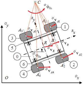
Figure1. PIAPGRANITErobotduringtestsinacontainer filledwithsand(a),kinematicstructureoftherobot(b)
However,wheelslippagemayoccurwhilethe robotismoving.Themeasuresofthatslippageare instantaneouslongitudinalslipratios ���� andmean longitudinalslipratio���� (longitudinalslipratioofthe wholerobot).
Thoseslipratiosaregivenwiththeformulas:
–wheelcircumferentialvelocity,
–distancetraversedbypoint R oftherobotinlon‐gitudinaldirection,�������� –desireddistancetraveledby point R whenrollingwithoutslip.
Forthepresentinvestigations,thefollowing assumptionsareadopted:
‐ wheelsaretreatedasrigidbodies, ‐ theso‐calledmulti‐passeffect(inwhichafollow‐ingwheelissubjecttosmallerrollingresistance, becauseitmovesinarutmadebyaleadingwheel) arenotconsidered,
‐ treadblocksoftiresareneglected.
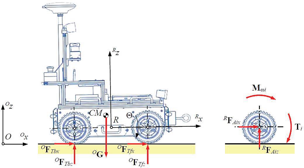
Amulti‐bodydynamicsmodelwasderivedforthe robot.Itwasassumedthatontherobotacttheground reactionforces,i.e., ��F���� =[����������, ����������, ����������]�� (��= 1,…,4)andgravityforce ��G =���� ��g (Fig.2a),where ���� isrobottotalmass, ��g =[������, ������, ������]�� the vectorofgravityacceleration,andtheleftsuperscript R meansthatmentionedvectorsareexpressedinthe movingcoordinatesystemattachedtotherobot.
Thefollowingindexesareintroducedforindivid‐ualpairsofwheels: f –frontwheels(��=1,2), b –rear wheels (��=3,4).Oneachwheel,apartfromforce ofgravityandforcesfollowingfromtheinteraction withtheground,actdrivingtorque ��T�� =[0,����,0]�� andmomentofmotionresistance��M���� =[0, M����,0]�� (Fig.2b).
Asaresultofthereductionofforces ��F���� tothe axesofrotationofwheels,theforces ��F���� = ��F���� = [����������, ����������, ����������]�� areobtained.
Themulti‐bodydynamicsmodelisbasedonthe followingequationsofdynamicsforthewholevehicle andforindividualwheels(associatedwiththeirspin):
Θ and ���� = ���� –angularaccelerationsofrotationof respectivelymobileplatformandwheelaboutmen‐tionedaxes, ���������� and ���������� –componentofthe linearaccelerationoftherobotmasscenter.
Thedevelopedmodelenablesthesolutionofthe forwarddynamicsproblemfortherobot.According tothismodel,inasingletimestepofsimulation,the followingquantitiesaredetermined:
1) Instantaneousslipratiosforwheels���� (��=1,…,4) andfortherobot���� fromequations(2)and(3).
2) Geometricquantitieslikemaximumwheelsinkage ��0�� andanglesofwheel‐terraincontact ��1�� and ��2�� =����2��1�� (Fig.3a).
3) Soilsheardeformation ����(��1��)accordingto[13] andwheelsinkage ����(��1��) intherangeofwheel‐terraincontactanglesfrom −��2�� to ��1�� basedon dependencies:
����(����)=����((��1�� −����)−(1−����)(sin��1�� sin����)), (8) ����(����)=max(��0�� −����(1−cos����),0). (9)
4) Pressure����(��1��)accordingtoBekker[11]:
����(����)=��(����(����))�� = ���� ���� +���� (����(����))�� , (10) where: ����(����)–cohesive(frictional)modulusof terraindeformation, n –terraindeformationexpo‐nent.
where: ������ =��/2−��������, ������ =−��/2−��������, �������� and �������� –robotmasscentercoordinates, �������� –robotmassmomentofinertiaabouttheaxisparallel to ���� andpassingthroughrobotmasscenter, �������� –wheelmassmomentofinertiaaboutitsspinaxis,E=
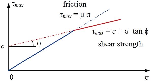
5) Normalstress����(��1��)≈����(��1��),maximumshear stress ����������(��1��),basedonmodi iedMohr‐Coulombfailurecriteria[18](Fig. 3b)including thecaseofmovingtiresurfacewithrespecttosoil: ����������(����)=min(��������(����),��+����(����)tan��), (11) thatistakingintoaccountsoilcohesion c,internal frictionangle��andcoef icientofstaticfriction���� forthewheel‐terrainpairaccordingto[19].

6) ShearstressesaccordingtoJanosi‐Hanamoto hypothesis[12]intherangeofwheel‐terrain contactanglesfrom−��2�� to��1��:
where K isthesheardeformationparameter.
7) Forcesandmomentsofforcelike:staticnormal load����,tractionforce����,motionresistanceforce ������ andmomentofmotionresistance������ basedon theknownstressdistributionoverwheelcircum‐ference,accordingtoformulasin[13],i.e.,basedon equations:
and inally,resultantforces:longitudinal ���������� = ���� +������ andnormal ���������� =���� +������,which includescomponentforceresultingfromthetire‐groundsystemdamping������ =������ 0��sgn(��0��).
8) Linearandangularaccelerations,i.e.: ����������, ����������, Θ and ���� (��=1,…,4),forthemulti‐body systemoftherobotbasedontheequationsof dynamics(4)–(7).
Itshouldbenoted,thatvelocities ������, ����������, ���� necessaryfordeterminationofslipratios ���� and ���� inthe irststageofthealgorithmdescribedabove, coordinatesofcentersofwheelsnecessaryforcalcu‐lationofwheels’sinkage��0�� andangles��1�� and��2�� in thesecondstageofthatalgorithmaretakenfromthe previoustimestepofcalculations.
NumericalstudieswereconductedintheMat‐lab/Simulinkenvironment.
Aspartofthepreliminarysimulationtests,a numericalveri icationofthewheel‐groundinterac‐tionmodelwascarriedout.Inthesestudies,theprevi‐ouslymentionedparametersofthismodelweretaken intoaccount.
Inthecalculations,itwasassumedthatthechange oftheangle���� ∈⟨−��2��,��1��⟩willbeimplementedwith astep Δ��=��/180 rad.Moreover,itwasassumed that ��2�� =����2 ��1��,where ����2 =0.4.Calculations wereperformedforthefollowinginputdata: �������� = 0.0815 m, ���������� =1 m/s, ���� =14 rad/s, ���� = 1Nm.Theassumedangularvelocityofthewheelsis themaximumfortheGRANITErobotandcorresponds tothecircumferentialvelocityequalto������ =1.4m/s.
Figure4showsthestressdistributions����(����)and ����(����)onthewheelcircumference,theresultingforces ����������, ���������� andmomentofforce M���� aswellasthe inputandoutputdatafortheanalyzedtest.
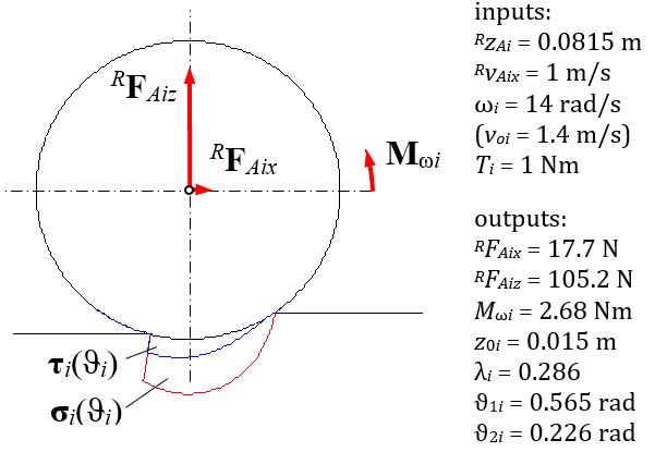
Illustrationofthedistributionofstresses ����(����) and ����(����) onthewheelcircumferenceaswellas theresultingforces ��F������, ��F������ andmomentof force M����
������ =−����(����)2 ��1�� −��2�� ����(����)d����, (16)
Itshouldbenotedthattheobtainedvalueofthe groundnormalreactionforceisequalto ���������� = 105.2N.Inthecaseoftheanalyzedtire,suchaforce wouldcauseitsradialdeformationequalto Δ���� = 0.0026m,whichissmallincomparisonwiththemax‐imumgrounddeformation��0�� =0.015m.
Inturn,Figure5presentsdistributionsofdeforma‐tionsofthegroundandstressesonthewheelcircum‐ferenceasafunctionoftheangle���� fortheanalyzed case.
Accordingtothepreviouslygivenformulas,after integrationofstresses w��(����), r����(����), f��(����), f����(����) and����(����),theresultantforcesandmomentofforce, areobtained,i.e.: W��, R����, F��, F���� and M����.
Itcanbenoticedthatthevalueoftheforce F���� is signi icantlyin luencedbythestressdistributionin therearpartofthetireinrelationtothedirectionof movement.
Inparticular,stress r����(����)hasnegativevaluesin therange ���� ∈(0,��1��) whilstpositivevaluesinthe range ���� ∈(−��2��,0),whilestress f��(����) haspositive valuesintherange���� ∈(−��2��,��1��),withthelargestin therange���� ∈(−��2��,0).
Aspartofthemainsimulationstudiesforthe entirerobot,thelongitudinalmotionfordesiredmax‐imumvelocities ������ from0.2m/sto0.7m/swas analyzed.Desiredmaximumacceleration���������� dur‐ingspeedingupandbraking,aswellasdesiredtotal distance���� tobetraveledwerechosenindividuallyfor theparticularcaseofmotion.Desiredparametersof robotmotionaresummarizedinTable1
ThevaluesofthebasicparametersofthePIAP GRANITEmobilerobotusedinsimulationstudiesare showninTable 2.Soilparametersrequiredbythe adoptedmodelandbasedonwork[14]arepresented inTable3
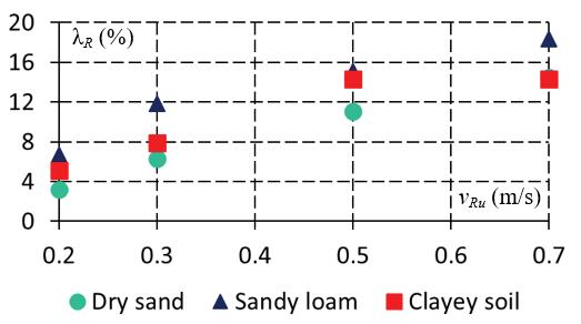
Theaggregatedresultsoftheresearchareshown inFigure 6.Itcanbenoticedthatthesmallestslip ratiosarefordrysandandthelargestforsandyloam andthattheslipratiosincreasewithdesiredvelocity. Thelargestwheelsinkageoccursfordrysand,andfor theotheranalyzedgrounds,itismuchsmaller.The wheelsinkageincreasesslightlywithrobotvelocity.
Inthecaseofdrysand,wheelsinkageismuch largerincomparisontoradialdeformationofthetire, whichwouldoccuronrigidground.Tireradialdefor‐mationwouldbe2–3mmbecausetheradialstiffness ofthetireis������ =40,000N/m[17].Fortheremaining typesofground,wheelsinkageisofcomparableorder tothisdeformation.Thedrivingtorquesincreasewith velocity,i.e.,torquesincreasenearlytwotimeswhen comparingresultsfor0.2m/sand0.7m/scasesof desiredrobotvelocity.
InFigures7–10,detailedresultsforrobotmotion withdesiredvelocity �������� = 0.5m/sondrysand, sandyloamandclayeysoilareillustrated.
Figure5. Distributionsonthewheelcircumferenceof soildeformations:tangential ����(����) (a)andnormal ����(����) (b),aswellasstressesresultingfromthem: tangential ����(����) (c),normal ����(����) (d)andresultants: w��(����), r����(����), f��(����), f����(����)= r����(����)+ f��(����) (e–h)
Table1. Desiredrobotmotionparametersforthe investigatedcases
Table2. BasicparametersofthePIAPGRANITEmobile robotusedinsimulationstudies
Dimensions ��=0.425m, ��=0.59m, ���� =0.0965m, ���� =2⋅0.064m
Massesofthebodies ��0 =36.54kg, ���� =1.64kg
Robotmasscentercoordinates �������� =−0.012m, �������� ≈0m, �������� =0.06m
Massmomentsofinertia ������ =0.016kgm2 , �������� =0.51kgm2
Tireparameters ������ =40000N/m, ������ =1000Ns/m
Table3. Soilparametersassumedfortheresearch[14]
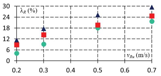
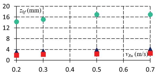
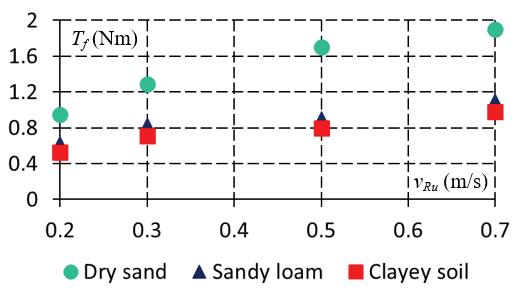
Figure6. Influenceoftypeofsoilanddesiredmotion velocityon:longitudinalslipratiosfortherobot(a), wheelsinkage(b),drivingtorques(c)
InparticularinFigure7,timehistoriesofdesired andactualrobotvelocitiesaswellascircumferential velocityresultingfromwheelspinarepresented.It canbenoticedthatduringsteadymotion,valueof theactualrobotvelocity �������� isnoticeablysmaller withrespecttodesiredvelocity ��������.Thisisbecause therobotdoesnotachievethedesiredacceleration, especiallyintheinitialstageofmovement.
This,inturn,resultsfromthehighvaluesofthe longitudinalslipratiosofthewheels ���� occurring especiallyduringtheaccelerationoftherobot.The robot’sactuallongitudinalvelocity �������� isclosestto thedesiredvelocity �������� forthecaseoftherobot movingondrysand.Inallcases,itcanbeseenthat themaximumcircumferentialvelocityofwheels���� is reachedwithadelay,whichresultsfromtheinclu‐sionofthedynamicsofthedriveunitsinthemodel, describedinpaper[17].
InFigures 8–9 thetimehistoriesoflongitudinal slipratiosandsinkageforfrontandrearwheelsare shown,respectively.Thetimehistoriesoflongitudi‐nalslipratiosaresimilarforfrontandrearwheels. However,adifferencecanbenoticedinthecaseof wheels’sinkage,duetothefactthatthecenterof massislocatedintherearpartofthevehicle.For thisreason,highervaluesareobtainedfortherear wheels.Similartothevelocity,thetimehistoriesofthe longitudinalslipratiosaresimilartoeachotherforthe
analyzedgroundcases,butduringaccelerationthey areapparentlythesmallestforthemovementondry sand.However,therearelargedifferencesinthetime historiesofwheels’sinkagefortheanalyzedtypesof theground.De initelythehighestvaluesofwheels’ sinkageoccurfortherobot’smovementondrysand. Inturn,thesmallestvaluescanbeseeninthecaseof clayeysoil.
Finally,inFigure 10,thetimehistoriesofdriving torquesforfrontandrearwheelsareillustrated.Dur‐ingacceleration,thehighestvaluesofdrivingtorques areachievedwhentherobotmovesondrysand.Inthe caseofothergrounds,similarresultswereobtained, moreover,thedrivetorquesforthefrontandrear roadwheelsarelessdifferentiatedinrelationtothe movementondrysand.
Simulationstudieswerealsocarriedouttoanalyze theimpactofwheelgeometricparametersonlongitu‐dinalslipratios,wheelsinkageanddrivingtorques.
Inthisresearch,inrelationtostandardcon igura‐tionoftherobot,thefollowingwheelsolutionswere analyzed:
1) wheelswithwidthreducedby50%,
2) wheelswithadiameterincreasedby50%.
Theresultsofsimulationresearchindicatethat fortheanalyzedrobotmotionvelocities,changing thegeometricparametersofthewheelshasasmall impactonthedrivingtorques.
Figure7. Timehistoriesofdesiredvelocity ��v���� and actualvelocity ��v���� oftherobotaswellas circumferentialvelocityofwheels ���� obtainedin simulationoftherobot’smovementwiththemaximum velocity ������ =0.5 m/son:drysand(a),sandyloam(b) andclayeysoil(c)
Figure9. Timehistoriesofsinkageforfrontandrear wheelsobtainedinsimulationoftherobot’smovement withthemaximumvelocity ������ =0.5 m/son:drysand (a),sandyloam(b)andclayeysoil(c)
Figure8. Timehistoriesoflongitudinalslipratiosfor frontandrearwheelsobtainedinsimulationofthe robot’smovementwiththemaximumvelocity ������ =0.5 m/son:drysand(a),sandyloam(b)and clayeysoil(c)
Figure10. Timehistoriesofdrivingtorquesforfrontand rearwheelsobtainedinsimulationoftherobot’s movementwiththemaximumvelocity ������ =0.5 m/s on:drysand(a),sandyloam(b)andclayeysoil(c)
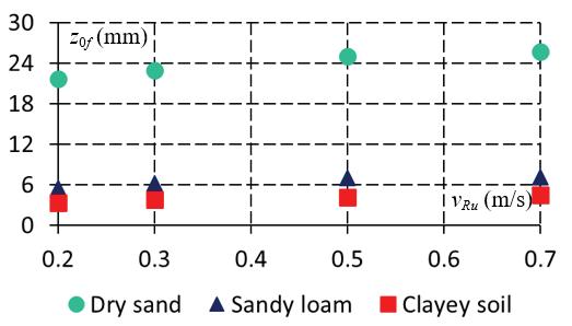
Whenwheelswithasmallerwidthwereused, slightchangesinlongitudinalslipratiosandasignif‐icantincreaseinwheelsinkagewereobserved.The changeinwheelsinkagecanbeseenfromthecom‐parisonoftheresultsshowninFigure6bforwheels withalargerwidthandinFigure11forwheelswith asmallerwidth.Thisobservationisconsistentwith theeffectsofpreliminaryexperimentaltestsforthe PIAPGRANITErobotandwasthereasonfortheuse ofwheelswithlargerwidth.
Theresultsofsimulationstudiesalsoindicatethat theuseofwheelswithadiameter50%largerleads toareductioninwheelsinkage,butthischangeis notsigni icant.However,theuseoflargerdiameter wheelsleadstoasigni icantreductioninlongitudinal slipratios,especiallyathighervelocities.Thiscanbe seenbycomparingtheresultsshowninFigure6afor wheelswithasmallerdiameterwiththeresultsin Figure12forwheelswitha50%largerdiameter.
Withinthispaperthesimulationstudiesofin lu‐enceoftypeofdeformablegroundonlongitudinal motionoflightweightwheeledrobotwascarriedout.
Investigatedcasesincludedfourdesiredvelocities ofmotion,i.e.:0.2m/s,0.3m/s,0.5m/sand0.7m/s andthreetypesofground:drysand,sandyloamand clayeysoil.
Forallthosecases,aggregatedresultsofwheelslip ratio,wheelsinkageandwheeldrivingtorquewere
presented.Detailedresultsforthecaseof0.5m/s velocityonallanalyzedtypesofsoilwerealsoshown. Thefollowingmainconclusionscanbedrawnfrom theconductednumericalresearch.
Ifalightweightwheeledmobilerobotmovesona deformableground,then:
‐ longitudinalslipratiosigni icantlyincreaseswith desiredvelocity;
‐ wheelsinkageincreaseswithdesiredvelocity–in caseofmotionondrysand,wheelsinkageismuch largerthanradialdeformationoftirewhichwould occurforcomparablewheelloadonrigidground;
‐ wheeldrivingtorquesincreasewithvelocityand reachthelargestvaluesforrobotmotionondry sand;
‐ changingthewheelwidthsigni icantlyaffectswheel sinkage,i.e.,itishigherfornarrowerwheels;
‐ changingthewheeldiametercauses,inturn,a changeinthelongitudinalslipratios,i.e.,they decreaseasthewheeldiameterincreases.
Thescopeoffurtherresearchmayinclude:
‐ modelingthedynamicsofbothlightweightand heavyvehiclesusingwheelswith illingsofvarious mechanicalproperties;
‐ simulationstudiestakingintoaccounttiredeforma‐tion,treadblocksandmulti‐passeffectintiremodel;
‐ experimentalstudiesoftherobotmotiononsandy loamandclayeysoil;
‐ simulationandexperimentalstudiesofrobotturn‐ingandrotationinplaceforvarioustypesofthe ground.
MaciejTrojnacki∗ –WarsawUniversityofTechnol‐ogy,FacultyofMechatronics,InstituteofMicrome‐chanicsandPhotonics,Boboli8,02‐525Warsaw, Poland,e‐mail:maciej.trojnacki@pw.edu.pl.
PrzemysławDąbek –ŁUKASIEWICZResearch Network—IndustrialResearchInstitutefor AutomationandMeasurementsPIAP,Al. Jerozolimskie202,02‐486Warsaw,Poland,e‐mail: przemyslaw.dabek@piap.lukasiewicz.gov.pl.
∗Correspondingauthor
[1] K.Zhou,S.Lei,andX.Du.“Modellingand dynamicanalysisofslippagelevelforlarge‐scaleskid‐steeredunmannedgroundvehicle,” SciRep,vol.12,no.1,Art.no.1,Sep.2022,doi: 10.1038/s41598‐022‐20262‐z.
[2] J.Guo,H.Gao,L.Ding,T.Guo,andZ.Deng.“Linear normalstressunderawheelinskidforwheeled mobilerobotsrunningonsandyterrain,” Journal ofTerramechanics,vol.70,pp.49–57,Apr.2017, doi:10.1016/j.jterra.2017.01.004.
[3] M.Ciszewski,M.Giergiel,T.Buratowski,andP. Małka, ModelingandControlofaTrackedMobile
RobotforPipelineInspection.SpringerNature, 2020.
[4] L.Liangetal.“Model‐BasedCoordinatedTrajec‐toryTrackingControlofSkid‐SteerMobileRobot withTiming‐BeltServoSystem,” Electronics,vol. 12,no.3,Art.no.3,Jan.2023,doi:10.3390/elec‐tronics12030699.
[5] A.J.Moshayedi,A.S.Roy,S.K.Sambo,Y.Zhong, andL.Liao.“ReviewOn:TheServiceRobotMath‐ematicalModel,” EAIEndorsedTransactionson AIandRobotics,vol.1,pp.e8–e8,Feb.2022,doi: 10.4108/airo.v1i.20.
[6] K.Peng,X.Ruan,andG.Zuo.“Dynamicmodel andbalancingcontrolfortwo‐wheeledself‐balancingmobilerobotontheslopes,”in Proceedingsofthe10thWorldCongressonIntelligent ControlandAutomation,Jul.2012,pp.3681–3685.doi:10.1109/WCICA.2012.6359086.
[7] P.Lichota.“WaveletTransform‐BasedAircraft SystemIdenti ication,” JournalofGuidance,Control,andDynamics,vol.46,no.2,pp.350–361, Feb.2023,doi:10.2514/1.G006654.
[8] S.SutuloandC.GuedesSoares.“Analgorithmfor of lineidenti icationofshipmanoeuvringmath‐ematicalmodelsfromfree‐runningtests,” Ocean Engineering,vol.79,pp.10–25,Mar.2014,doi: 10.1016/j.oceaneng.2014.01.007.
[9] J.Giergiel,K.Kurc,andD.Szybicki.“Identi ica‐tionoftheMathematicalModelofanUnderwa‐terRobotUsingArti icialInteligence,” MechanicsandMechanicalEngineering,2014,Accessed: Jan.16,2024.[Online].Available:https://www. semanticscholar.org/paper/Identification‐of‐the‐Mathematical‐Model‐of‐an‐Giergiel‐Kurc/5 b4cfa76e8916013fa613c40ff06d3a966542853
[10] A.PerrusquíaandW.Yu.“Identi icationandopti‐malcontrolofnonlinearsystemsusingrecurrent neuralnetworksandreinforcementlearning:An overview,” Neurocomputing,vol.438,pp.145–154,May2021,doi:10.1016/j.neucom.2021. 01.096.
[11] M.G.Bekker, Off-the-roadLocomotion:Research andDevelopmentinTerramechanics.University ofMichiganPress,1960.
[12] J.Y.Wong, TheoryofGroundVehicles,3rdEdition, 3rdedition.NewYork:Wiley‐Interscience,2001.
[13] Sh.Taheri,C.Sandu,S.Taheri,E.Pinto,andD. Gorsich.“AtechnicalsurveyonTerramechan‐icsmodelsfortire–terraininteractionusedin modelingandsimulationofwheeledvehicles,” JournalofTerramechanics,vol.57,pp.1–22,Feb. 2015,doi:10.1016/j.jterra.2014.08.003.
[14] K.IagnemmaandS.Dubowsky, MobileRobots inRoughTerrain:Estimation,MotionPlanning, andControlwithApplicationtoPlanetaryRovers. Springer,2004.
[15] L.Ding,H.Gao,Z.Deng,K.Yoshida,andK. Nagatani.“Slipratioforluggedwheelof planetaryroverindeformablesoil:de inition andestimation,”in 2009IEEE/RSJInternational ConferenceonIntelligentRobotsandSystems,Oct. 2009,pp.3343–3348.doi:10.1109/IROS.2009. 5354565.
[16] Z.Wangetal.“Wheels’performanceofMars explorationrovers:Experimentalstudyfromthe perspectiveofterramechanicsandstructural mechanics,” JournalofTerramechanics,vol.92, pp.23–42,Dec.2020,doi:10.1016/j.jterra.202 0.09.003.
[17] M.TrojnackiandP.Da̧bek.“Studiesofdynamics ofalightweightwheeledmobilerobotduring longitudinalmotiononsoftground,” Mechanics ResearchCommunications,vol.82,pp.36–42,Jun. 2017,doi:10.1016/j.mechrescom.2016.11.001.
[18] G.N.B.Hathorn,K.Blackburn,andJ.L.Brighton. “AnInvestigationintoWheelSinkageonSoft Sand,” TireScienceandTechnology,vol.42,no.2, pp.85–100,Apr.2014,doi:10.2346/tire.14.42 0201.
[19] “Tirefrictionandrollingcoef icients,”HPWiz‐ard.Accessed:Jul.25,2023.[Online].Available: https://hpwizard.com/tire‐friction‐coefficient. html
Submitted:13th September2022;accepted:6th March2023
DOI:10.14313/JAMRIS/4‐2023/27
Abstract:
Minimally‐supervisedhomerehabilitationhasbecome anarisingtechnologicaltrendduetotheshortages inmedicalstaff.Implementingsuchrequiresproviding advancedtoolsforautomaticreal‐timesafetymoni‐toring.Thepaperpresentsanapproachtodesigning thementionedsafetysystembasedonmeasurements andmodellingtheinterfacebetweenapatient’smuscu‐loskeletalsystemandarehabilitationdevice.Thecon‐tentcoversthesegmentationofpatientsregardingtheir healthconditionsandassignsthemsuitablemeasure‐menttechniques.Thedefinedgroupsaredescribedby thehazardswithwhichtheyaremostendangeredand theircauses.Eachcaseiscorrelatedwiththeappropriate datatypethatmaybeusedtodetectpotentialrisk. Moreover,aconceptofusingpresentedknowledgefor trackingthesafetyofbonesandsofttissuesaccordingto thebiomechanicalstandardsisincluded.Thepaperforms asetofguidelinesfordesigningsafetysystemsbasedon measurementsforrobot‐aidedhomekinesiotherapy.It canbeusedtoselectanappropriateapproachregarding aspecificcase;whichwilldecreasecostsandincreasethe accuracyofthedesignedtools.
Keywords: Biosignals,Biomechanics,Homerehabilita‐tion,Kinesiotherapy,Minimally‐supervisedtreatment, Rehabilitationrobotics
1.Introduction
Kinesiotherapyistreatmentwithmotiondesigned torestoremaximumfunctionalityofpatients.Itspur‐poseistorecoverfromdiseasesofthemusculoskele‐talsystem.Duringkinesiotherapyofextremities,a physiotherapistinteractsphysicallywiththepatient’s limbsinaspeci icwaytoregaintheirmobility[61].
Bringingbackmaximumfunctionalityisessen‐tialforbasicdailyactivities(ADL).Themotortreat‐mentoftenrequiresalotofprofessionalphysical engagement,whichmaybeovertakenbyrehabili‐tationrobots.Moreover,workingwithpeoplewho donothavetheabilitytositorstandthemselves oftenrequiresuprightstandingwiththehelpofup tothreephysiotherapists[21].Inaddition,theageing societyrequiresmoreintensiveandfrequenttreat‐mentwhilethenumberofmedicalpersonnelongo‐inglydecreases.Hence,themostsigni icantproblemis
aninsuf icientnumberofphysiotherapistsandcare‐giversinnursinghomes[50].Itispossibletoreduce theparticipationofprofessionalsinthetherapyeven whilebeingdependentonfamilymembers.However, thisrequiresthedevicestosupportperformedexer‐cisesinapreciseandcontrolledway[53].Research indicatesadvantagesofprovidingstrokepatientsand peoplewithparesis,whorequirepermanentrehabili‐tation,withtransportable,lightweight,andwearable devices.Suchmaybeinvolvedinthepost‐discharge homerehabilitation[60].
DuetotheCOVID‐19pandemic,patientsneeding constanttherapywereseverelydisadvantaged.This wascausedbypandemicrestrictionsinhumanmeet‐ings[25],overcrowdingofhospitals,andtheshortage ofhealthcaremembers.Toavoidsuchsituations,it iscrucialtodevelopwell‐validatedtoolsforremote homerehabilitation[26].
Consideringthementionedconditions,adapting rehabilitationdevicestohomeself‐useisanarising needandchallengeformedicalrobotics.Asthether‐apistmaybenotprovidedwithhapticfeedbackdur‐ingremotehomerehabilitation,developingarobust safetysystemiscritical[80].Suchshouldanalyse dynamicsoftherehabilitatedbodysegmentandaddi‐tionalmeasurementstoassessthesafeoperationof auserwithoutinvolvingaphysiotherapist[23].The followingpaperpresentsanapproachtomodelling patients’physicalloadstodetectpotentialpainor discomfortautomatically.Thisispossibleforpartic‐ularcasesbymeasuringandinterpretingbiosignals ordynamicparameters.Thepaperclassi iespatients accordingtotheirdisorderslevel.Basedontheselev‐els,potentialhazardsduringkinesiotherapyarelisted andmatchedwiththecorrespondingmeasurements. Thesemaybeusedtobuildamodelenablingcontinu‐oushuman‐lesssafetymonitoring.
Basedonaliteratureoverview,thepaperconsists ofasystematicanalysisofthepotentialautomatic detectionofhazardoussituationsduringremotehome treatment.Thisincludesdiseasecasesegmentation, possiblecausesofinjuries,andmeasurementmeth‐ods.Withthese,amultibodymodelmaybecreated andusedtoassessthesafetyofthetreatment.
TheScopus,ResearchGate,GoogleScholar,and PubMeddatabaseswereanalysedtocreatethis paper.Thefollowingkeywordswereused:home telerehabilitation,kinesitherapy,stroke,paresis, spasticity,extremityexoskeleton,paindetection, measurablebiologicalsignals,ROMmeasurement, OpenSim.92articleswerereviewedwiththe limitationofbeingpublishedin2016orlater,of which37wereconsiderednottocontributemuch tothispaper.Papersdescribingtheexactconcept ofspeci icrehabilitationdeviceswererejected. However,itisworthnoticingthatmostofthem assumetheconstantpresenceofaphysiotherapist nexttothepatientorpriorlimitingjointsrangeof motion(ROM),whichaffectsthedevice’sworking area.Papersmainlydealingwiththepharmacological treatmentofstrokes,spasticity,orparesiswerealso rejected,asthisisnotrelevantfortheuptakentopic.
3.1.SegmentationofCases
Thepatientsweresegmentedinto ivegroupsto assignthemcorrespondingpotentialrisks.Thanksto this,thenumberofmeasurementtechniquesneeded forsafetymonitoringislimitedforeverycase.The de inedgroupsare:
1) Patientswithsensationaftermechanicaltrauma (e.g.,fractures)orlightmusculoskeletaldisor‐ders(e.g.,jointcalci ication)andpost‐surgical patients–withapossiblecompletereturntopre‐injuryperformance
2) Patientswith laccidmuscles,deprivedofsensa‐tion
3) Patientswith laccidmuscles,withsensation
4) Spasticpatients,deprivedofsensation
5) Spasticpatients,withsensation
Thepatientswithmuscle laccidityareunderstood astheoneswithmissingconnectionsbetweenthe brainandspinalcordcircuitsessentialforvolun‐tarymovement[22].Spasticityisamotordisorder characterizedbyavelocity‐dependentexaggerationof stretchre lexesresultingfromabnormalintraspinal processingofprimaryafferentinput.Suchmalfunc‐tioningimpliesincreasedmuscletone,enhancedten‐donre lexes,andextendedre lexzones[14]andis usuallytheresultofstroke[8].Tocorrectlyreferto individualcasesinthepaper,theyareassignedwith thenumbersoftheabove‐proposedsegments.
Thedivisionaboveincludescasesofpatientseli‐gibleforrobotichomerehabilitationandreferstothe partofthebodyrehabilitated(e.g.,whileperforming kinesiotherapyofthelowerlimbofapatientwiththe laccidlowerhalfofthebodyandsensation,theyare treatedasthegroup3–eventhoughtheirupperhalf ofthebodymaybenotaffectedbyanydisorder).For everygroup,thesignalswhichcanbemeasuredfor paindetectionpurposeswereselected.Theproposed approachtodetectriskpriortopatients’injuriesby theroboticrehabilitationsystemsispresentedbelow.
Selectionoftheappropriateapproachto measurementspriortoandduringkinesitherapeutic robot‐aidedsessionsiscriticaltoautomatingthe process.Themethodsmaybecombinedandused alongwitheachothertoimprovethereliabilityof thesafetysystemofthedevice.Currently,themost commonsensorsforrehabilitationdevicesareIMU, encoders,pressuregauges,andEMGsensors.The irst twoareusedtoobtaininformationonthedevice’s kinematicscon iguration,whiletheothersarefor biofeedback[19, 72].Thissubsectionpresentsan overviewoftheconsideredtechniquesandcorrelates themwiththesegmentspresentedbefore.
Measurementofthepatient’srangeofmotion
Measurementofthepatient’srangeofmotion(ROM) isconnectedwithactivelyexercisedjoints.The resultedvaluesdescribetheoperationalspaceofthe individualbodysegment,wheretheexercisemay beperformedwithoutpainoranyriskoftrauma. Suchmeasurementmayberealisedmanuallywith goniometersorwitharehabilitationdeviceitself, e.g.,bytheSFTRmethod[31].Beforestartingthe actualtreatmentsession,thedeviceshouldlauncha measuringmoduletodeterminethepatient’sROM andadjusttheexercisespace.
Thereisnocertaintythatstayingwithin singlejointlimitswillensurethepatient’ssafety duringcomplexmovements.Inotherwords, thedecompositionofacomplexmotionintothe appropriatecomponentsinthefundamentalplanes: sagittal,frontalandtransverse,doesnothave tocorrespondtothesumofthesemovements intermsofthemuscleloads.Moreover,sucha measurementshouldtakeplaceseveraltimesthe duringrehabilitationprocesstoconsiderpotential ROMincreaserelatedtotheconvalescenceprocess[2]. However,thistime‐consumingprocessdoesnotfully safeguardfurtherautomatickinesiotherapy.Ifsucha calibrationistobeperformedwithoutanadditional operatorofthesystem,eitherintelligentalgorithms havetosensemotionlimitsorthedevicemust receiveequivalentinformationfromapatient.The irstapproachisdif iculttoimplementforpatients withsevereneuraldiseases.Ontheotherhand, con irmingtheendofpossiblemotionrequiresthe user’scapabilityofphysicalinteractionwiththe human‐machineinterface(HMI)orimplementation ofvocalcommands.Thisimpliestheneedforan excellentcommandandsoundrecognitionsystem, potentiallywithanadvancedneuralnetwork[37]. Theserequirementsalsoaffectthenumberofpatients whomayusethedevice.
TomeasurepulseorECG,thedevicehastobe equippedwiththededicatedsensors.Asthesevere stressrelatedtopainsensationscausesthechange inreadings[71],thistechniquecanbeusedto detectemergencystatesoftherehabilitation
system.However,thevaluesofrestingheartrate andthemeasurementsduringexercisingvaryfor individuals[78].Additionally,theabnormalitiesmay beregisteredtoolatefortherobottoreactbefore harmingthepatient.Moreover,theexpectedaccuracy ofaround60–80%andnodistinctionbetweenpain levelsmaynotbeenoughreal‐timepainrecognition forrobot‐aidedkinesiotherapy[56].
Thesafetyalgorithmscanbebasedonthemultibody modelofthecooperatingdeviceandmusculoskeletal system.However,thisapproachrequirescomparing computedresultsofloadswithinindividualtissues withtheirstrengthparametersdifferentforeveryper‐son.
Themostvulnerabletoinjuriesaretendonsand ligaments[42].Forthisreason,machinesshouldnot exceedthestrengthlimitsofthesetissues.Itispartic‐ularlychallengingtoobtaindataontheirparameters, suchasYoung’smodulus.Thecorrespondingexper‐imentaltrialsareusuallycarriedoutonanimals[7] ortissuesfromthedeceased[34],whichdonotfully correspondtothetissuesofalivehumans.Moreover, tissuepropertieschangewithage,gender,andexperi‐encedillnesses[59].
Topreventhazardoussituations,estimatingthe tensilestrengthismostcriticalforindividualsoft tissues,astheyaremostvulnerabletodamagein thisdirection[3].Beforethetreatment,theirvalues maybeobtainedwithaspeci icdevicesuchas MyotonPRO[5].Themeasurementmethodconsists ofregisteringthedampednaturalvibrationsofsoft biologicaltissueintheformofanaccelerationsignal andthencalculatingthedesiredparameters.Such technologyenablesmeasuringthetone,stiffness, lexibility,relaxation,andcreepoftissues[5].The proposedsolutioncouldalsobetransferredto therehabilitationrobotbyequippingitwitha dedicatedsensorysystem.Nevertheless,thereare alsolimitationstothismeasurementtechnique,e.g., theresultsarelessaccurateforobesepatientsaswell asthedeeplylocatedandtoothintissuesaredif icult toworkwith[1].
EDAmeasurement
EDAiselectrodermalactivity,demonstratedtobe effectiveinarousalestimation[73].Asapatient’s sweatingchangesattimesofseverestress[32], analysingcorrelatedEDAsignalscancontributeto detectingincreasingpain.Thistechnologyisbeing continuouslydeveloped,anditdoesnothavemany validatedapplicationsyet[4].Thereareserious doubtswhetheremotionssuchasjoyorstresscaused byprovidingtreatmentbyarobot,notahuman,will notcauseexcessivesweating[64].Suchaneffectcan leadtoconfusionofhazardsituationswitharegular operationofthedevicebytheautomaticsafety monitoringsystem.Forthisreason,implementing EDAwithinareal‐timesystemfordetectingrisksin homerobot‐aidedtreatmentisnotsuggested.
EEGmeasurement
EEG,electroencephalography,isanon‐invasive methodofanalysingbrainelectricalactivitybased ontherecordingsfromthescalp.Asapatient’s intentionsaredetectablewiththismeasurement[46], arehabilitationrobotcanuseEEGsignalsfor predictivecontroltointeractwithauserandnot exceedtheirrangeofmotion[80].However,not everyintentionofmotionresultsinthemovement–itsimagemaybeenoughforthecorresponding areaofthebraintobecomeactive[49].Onthe otherhand,researchersprovedthatphysicalpain, particularlyacute[70],canbedetectedbasedon EEGwithanaccuracyofalmost95%andusedfor real‐timere lexinprostheses[75].Thisimplies theapplicabilityofthetechniqueforrobot‐aided rehabilitation.Nevertheless,usingadvancedEEG systemsisrelativelyexpensiveandrequiresprecise placementoftheelectrodesonapatient’sscalpto providerepetitiveresults[12].Thesemightbethe mainbarrierstousingsuchforhometherapy.
EMG,electromyography,maybeeitheraninvasive ornon‐invasiveinvestigationoftheelectrical activityofmuscleunitsorwholegroups.Registered signalsprovideinformationregardingthetemporal behaviourandmorphologicallayoutofactivemotor unitsduringmusclecontraction[68].Thismaybe usedtoestimateinternalstressinthesetissues andcomparethemwiththeirbiomechanicallimits. Thesafetysystemmustreacttosuddenpeaksin theregisteredsignals.Thesemayeitherberelated tothenociceptive lexionre lexcausedbypain stimuliorthespasticre lexcausedbyasudden noise,unexpectedtouch,orstress[13].Thetwo mentionedhavetobedistincted.Hence,theEMG maybeuselessfordetectinghazardoussituations forspasticpatientsinspasticity‐relatedsituations. Theresearchersalsopresentthemethodofdetecting painbasedonEMG‐registeredfacialexpressions. However,thisrequiresnon‐affectedfacialmuscles andgeneratessimilarproblemsasforEEG,including preciseplacementoftheelectrodes[39].The valuesregisteredwithEMGcanbeusedtoestimate temporarymuscletension[58].However,thesurface EMG,theonlyapplicablewithinrobot‐assistedhome kinesiotherapy,isvulnerabletonoisesfromelectrical devices,othermusclegroups,andfatlayers[77].
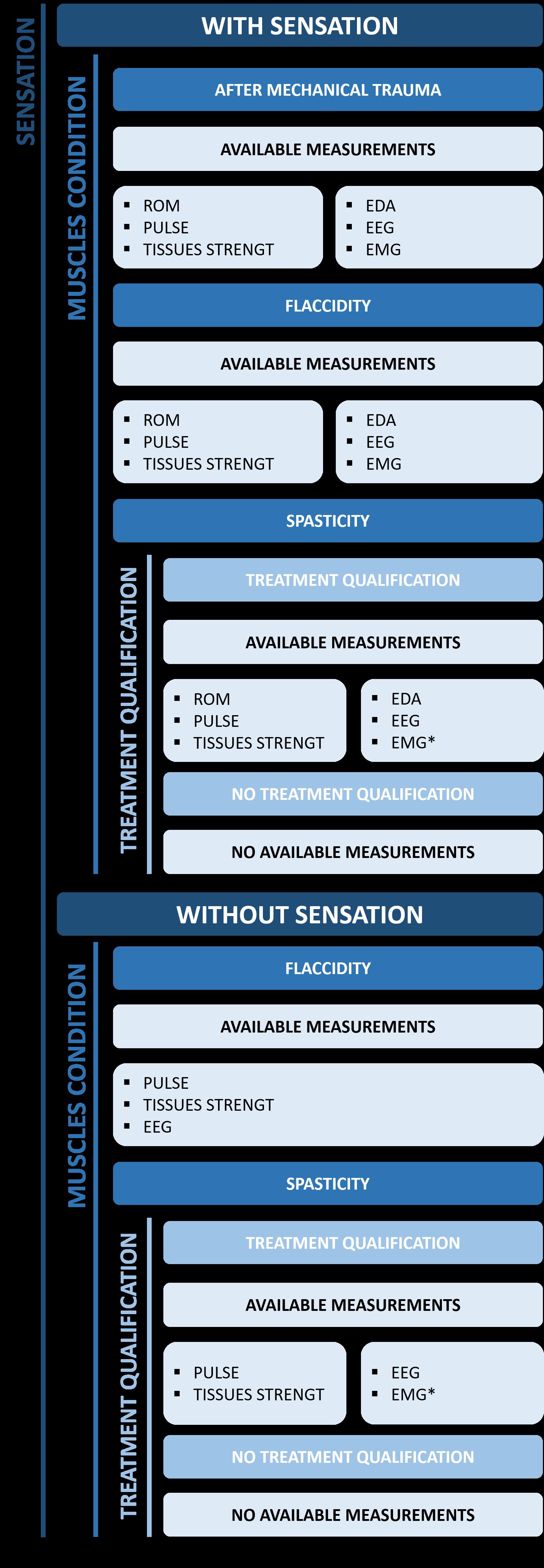
Inordertoproposethesolutiontailoredtothecapa‐bilitiesofaspeci icgroupofpatients,adecisiontree formeasurementselectionispresentedinFigure 1. The irststepistoassesswhetherapatienthasphysi‐calsensations.Itisassumedthatpost‐traumapatients meetthisrequirement–ifnot,theyareassignedto groups2or4.
Moreover,patientswithspasticityhavetobemed‐icallyquali iedforrobot‐aidedexercising.Thisdeci‐siondependsontheseverityoftheproblemaccording tooneofthescalessuchasAshworthscore,modi ied Ashworthscore,Tardieuscale,ormodi iedTardieu scale[74].Theoneswiththedegreeofspasticity exceedingacertainthresholdcannotworkoutby themselvesduetotheirspastic,uncontrolled,intense musclecontractions[14].Suchapre‐treatmentmed‐icalassessmentshouldbebasedonseveraldoctors’ independent,expertopinions[35].
Ontheotherhand,patientsdeprivedofsensation oftensufferfromexcessivesweating[33].Theyare unabletoidentifytheirownpainailments[33],and thus,theiravailablerangeofjointmobility.
AsmaybeobservedinFigure 1,patientsfrom groupnumber1aresuitableforallthemeasurement methods.Themostchallengingtaskistomeasure biologicalsignalsforgroup2becauseitisnotpossible togatherdatarelatedtotheirmuscletensionortheir senseofmotionlimits.
Moreover,thereisadifferenceintheapplicability ofEMGmeasurementsbetweennon‐spasticandspas‐ticpatients.Forthe irstgroup,thesensedelectrical signalsmaybecorrelatedwiththemuscularforces andthenanalysedregardingbiomechanicallimitsfor safeguardingpurposes.Whenitcomestothesecond group,theiruncontrolled,rapid,andseveremuscle contractionsmayturnEMGsignalsunabletobeused asdescribedabove.However,signi icantchangesin themeasuredsignalscanbeassignedtotheemer‐gencystopoftherehabilitationdevice(markedin Figure 1 asEMG*).Thismaycounteractthehazard ofmusclerippingduringtheinvoluntary,disease‐relatedcontraction.Furthermore,forpatientswithout sensation,theROMrangecannotbemeasuredasthey cannotfeeltheirphysicallimits.
Besidesthementionedabove,itisnecessarytobe awarethatforindividualcasesfallingintooneofthe proposedsegments,assignedmeasurementsmaynot giveexpectedresults.Therefore,thepatientshouldbe treatedas ittinganothergroup,eventhoughtheydo notmeetitscriteria.
Apartfromavoidingauser’sdiscomfort,theauto‐maticsafetysystemforrehabilitationrobotsshould preventsituationscausingphysicaldamagetotissues. Thismayberealisedbymodellingthecausesofpar‐ticularhazardsandcomparingtheirreal‐timevalues withestimatedthresholds.Table1containssegmen‐tationofthese.Iftheriskofaparticularcauseoccuring istypicallyneglectableduringrobot‐aidedtreatment, the“high‐riskgroups”cellislabelledas“lowrisk”.
Thebone‐relatedtraumasaretypicallyhazardous forthepatientsrehabilitatedaftersimilartraumas. Regardingsegment1ofpatients,itissimilarforthe injuriesofmuscles,ligaments,andtendons.Therefore, high‐riskgroup1*referstothepersonaftersimilar fracturesordamagetothesofttissues.Onthecon‐trary,B4traumamayonlyappearduringlong‐time forceappliedtotheextremity’ssegment,whichis noticeableasapainstimulusbypatientswithunaf‐fectedsensation.Thedevicemaybestoppedimme‐diatelyinsuchasituationandnotcauseanyharm. Onlygroups2and4arenotabletonoticesucha casethemselves.Therefore,anadditionalsafetysys‐temmonitoringcontinuousloadshastobeprovided.
Trauma Symbol Cause High-riskgroups Measurementtechnique(otherthan trackingdevice’sdynamicparameters)
Transversebonefracture
Impactedbonefracture
Thedevicehastoreacttotheriskofbonefractures beforeanactualdangeroussituationappears.There‐fore,nopain‐basedmeasurementswillbehelpful. Instead,theoverallsystemshouldbemonitoredbased onitsmultibodymodelsuppliedwiththemeasured dynamicparameters.Moreover,greenstickfractures andsimilar,morecomplexvariants(B4,B7,B8)may appearwhileexceedingnaturalROM.Therefore,this shouldalsobeimplementedforsafeguardingsuch cases.
Asthestrainsandcontusionsarelessseverethan othertypesoftraumarelatedtosofttissues,theymay bedetectedwithpain‐basedmethods.Moreover,they typicallyappearprecededbynoticeablephysicaldis‐comfort.Therefore,thedevicemaybestoppedbefore harmingtheuser.Formuscletearsandligamentor tendonruptures,thesystemhastoreactpriortothe contusion.Hence,apredictionbasedonthemulti‐bodymodelandmeasureddynamicparametersofthe deviceissuggested.
Moreover,asthemajorityofmuscles’andliga‐ments’traumas(notM3)arerelatedtotheforcegen‐eratedinthecorrespondingmuscles,theyarerelevant onlyfornon‐ laccidpatients.Furthermore,theirrisk maybetrackedwithEMG.Forthepatientswithno sensation,anadditionalsystembasedonthemulti‐bodymodelandthedevice’sdynamicsparametershas tobeprovided.
Thedamagetosofttissuesmayalsobecausedby exceedingtheindividual’sanatomicallimits.There‐fore,constantmonitoringofthedevice’scon iguration relatedtothemeasuredROMshouldberealised.
Apersonassignedtooneofthesegmentspre‐sentedbeforehandshouldbeassignedtothepoten‐tialrisksbasedonthe“high‐risk”columninTable 1 Subsequently,asensorysystemandamathematical modelshouldbebuilttodetectandreacttohazardous situations.Thankstosuchanapproach,arehabilita‐tiondevicemayimplementitsemergencyroutines whenriskappearstopreventharmtoauser.Asmay beobserved,detectingeverypossibletraumarequires trackingthedevice’sdynamicsparametersandbuild‐ingatleastasimplemultibodymodelofaphysical interfacebetweenamachineandahuman.
Themeasurementsproposedintheprevious section,alongwiththedynamicsparametersofthe device(drives’torquesandencoders’positions),can beusedtobuildamultibodymodelofthesystem. Suchcanbeusedtoestimateinternalforces,torques andstressesoccurringinthebodysegmentsduring atreatmentsession.Thesevaluesshouldremain belowtheacceptablethresholds,whichmayvary forindividualcases.Assumingcorrectestimations regardinganatomy,comorbidities,andapatient’s medicalhistoryregardingavailablebibliography sourcesenablesthebuildingareliablesafetysystem. Thefollowingsectionpresentstheindividualtissue strengthparametersforvariouscases.
Generally,inmaterialengineering,theleadingtest carriedouttoidentifythestrengthpropertiesofa materialistheuniaxialstatictensiletest.Themajor challengeistoselectthetestingsampleshape.This isduetothefactthatsofttissuesarepreparedpost‐mortem(tissuesofbloodvesselsandskintissues, amongothers)and,hence,theyarepre‐tensioned. Therefore,theirsusceptibilitytodeformationmakes itchallengingtopreparetheappropriate ittingof asample.Forthisreason,softtissuesareusually examinedintheformofabar[47].
Thereisastrongcorrelationbetweenanindividual’s gender,age,orbonetypeandthetissue’sstrength.For example,loadingawoman’sradiusorhumeruswitha torqueofapproximately61Nmwillcauseafracture witha50%probability[63].Thedifferencesinthe criticalvaluesmaybeassigni icantas100Nmforthe criticalbendingmomentofthehumerus,depending onthegender.Analysingshearforceinthisbone, itscriticalvalueis1.7kNforwomenand2.5kNfor men[63].
Itismuchmoredif iculttodamagethelowerlimb. Theprobabilityofaninjuryincreasesoutstandingly whentheforceof5kNisexceeded[63].Withinthe lowerlimbs,the ibulaisthemostvulnerablebone. Itstensilestrengthisuptotentimeslessthanthe femur’s[63].Formanyapplications,thecriticalbone resultantstresscanbetakenas150MPa[20]and shouldbescaledaccordingtotheindividualcase. Moreover,extraordinaryattentionshouldbegivento theweakestboneoftheexercisedbodypart.
Muscles
Thereisacorrelationbetweenthedirectionofmuscle tensionanditsforce.Moreover,harmtothesetissues istypicallycausedbythetendons’force,orexcessive strain[11].Forthisreason,musclesareoften analysedwithtendonsasuniformbodiesofaverage strengthproperties[41].Correlatedstress‐strain curvespresentthatastrainover0.4leadstoarapid increaseinstressashighas200kPa[63].Moreover, themaximumforceappliedtothemusclemaybe calculatedasthemultiplicationofPCSA,andestimated tetanictension,e.g.,22.5N/cm2 formammalian muscles[51].Thisrequiresmeasurementofthe initialmusclelengthsandmonitoringkinematics oftheextremityduringexercises.Hometreatment shouldberealisedwithalowereffortforthepatient’s safety.Aspresentedintheliterature,monitoring offorceoccurringinthissofttissuecanberealised bybuildingacomputationalmultibodymodelor analysingtheirmeasuredexcitation[15].Hence, apotentiallydangeroussituationresultingfrom exceptionalmuscletensioncouldbedetectedas therapidincreaseoftheEMGsignal,whichleadsto reachingbiomechanicalthresholds.
Thestrengthandstiffnessofligamentsandtendons dependonapatient’sageandlevelofphysicalactivity. Themaximumforcethatcanloadthesetissuesfora young,athleticpersonisestimatedas6.1kN,while foranolderpersonwithastaticlifestyle–only4.6 kN[16].About10%–15%extensionofthetendon causesstressbeyondtheelasticlimit[63].Thiscre‐atesstressofapproximately50kPaandresultsin adeformationof4mmonaverage[52].Theforce generatedinthetissueisthencloseto200N[20]. Forelderlypeople,Young’smodulusofligamentsand tendonsincreases.Theyaremoredif iculttostretch andbecomeless lexible.Nevertheless,theelastic‐ityofthesetissuesguaranteestheirproperfunction‐ing[20].
Moreover,theworkstateofthetissueisalsoacriti‐calfactorforestimatingsafetythresholds.Contracting tissuesgeneratemorestressandaremoreexposedto thedamagethantheextensingones[20].Ingeneral, Young’smodulusofthetendonmaybeestimatedas 0.9–1.4GPa[20].
Asmentionedbefore,thepropertiesoftissuesdif‐feramongindividuals.Thesolutiontopredictthe effectsofagivenexerciseforaspeci icpersonisto
createadigitaltwinofthepatientandarehabili‐tationdevice[27,80].Itispossibletobuildsucha mathematicalmodelinopensoftware,e.g.,OpenSim. Thegeometricalparametersofthefreemodelsmay bemodi ied,aswellasthestrengthparametersofthe tissues[65].
Modellingthephysicalinterfacebetweenareha‐bilitationdeviceandauserenablesthepredictionof thesystemdynamicsinreal‐time.Hence,hazardous situationsmaybemitigatedbeforetheyoccur[25]. Moreover,thismaycontributetooptimisingtherapy effects.
Internalforcesinthetissuesmaybeanalysed regardingtheexternalloadsapplied[62],alsoinan externalenvironmentastheexportedtimeseries[44]. Thankstothis,itispossibletosimulatetheresultsof themostdangerousmovementsforpatientswithpar‐ticulardiseasesandacertainage.Basedonthesesim‐ulations,thepatientmaybequali iedonlyforlimited accesstothedevice’sfunctionality.Thus,thehome treatmentremainssafe.Moreover,theregisteredEMG signalscanbeincludedinthemodelasadditional validationofthesimulations[55].However,inEMG‐basedcontrol,themajorchallengeissigni icantsignal noise[66].Duetotheneedto ilterthisout,almost real‐timeprocessingishindered.Inaddition,themea‐suredparametersvarybetweenindividuals.More‐over,thistypeofcontrolcanonlybeusedbypeople capableofgeneratinganelectricalactivityexceeding acertainthreshold[48].Therefore,theEMGmeasure‐mentsshouldnotbeconsideredastand‐alonetoolfor automaticpainmonitoring.
Withinthepresentedmethodology,buildingan accuratemodelofthepatientandthedeviceiscritical forprovidingthesafeoperationoftherehabilitation robot.Themodel’sgeometryshouldre lectareal‐life patient’sanatomy,whilethesimulatedtissueshaveto beprovidedwithadequatematerialparameters.The researchersprovethattheready‐madeopenhuman bodymodelsmaybeeffectivelyenhancedbyadding rigidmultibodymodelsoftherehabilitationdevices andusedasproposedinthepapers[40,62,65].
Mostoftheexistingrobot‐aidedrehabilitationsys‐temsneedthephysicalpresenceofaphysiothera‐pist[79].Forthisreason, indingavalidatedcontext forthepresentedproblemisdif icult.Moreover,the methodsofreal‐timesafetymonitoringbasedonmea‐surementsarenotthesameforallpatients.
Duringthetreatment,physiotherapistsmanu‐allyrecognisesoft(muscular)andhard(bone)resis‐tance[9].Theyknowhowmuchtoexceedthesoft resistancetoimproveapatient’sconditionwhile notexposingthemtoinjury.Thishapticfeedback withaprofessional’sexperienceneedstobetrans‐ferredintomachinealgorithms.Existingpainscales suchastheVisualAnalogueScale(VAS),theVerbal RatingScale(VRS),andtheNumericalRatingScale (NRS)[38]aresubjective.Moreover,theyaremainly basedonapatient’spreviousexperiencecomparedto thepresent[43].
Onthecontrary,theproposedsegmentation allowsfocusingonindividualdiseaseentitiesand developingdetectionmodelssuitableforspeci ic cases.Inthebeginning,therobot’saimshouldbe de ined.Thiscaneithersupportpeopleafterlighter injuries[17]orserveforagradualrecoveryofmotor activitiesforpeoplewithsevereimpairment[6].
Forthesecondcase,thedevicemaynotevencor‐rectinaccuratemovementsinitiallytoregainbasic mobilitywithoutthepain.Suchshouldbeincludedin therulesforhazardsdetectionalgorithms.
Arti icialintelligencecanbeusedforthesepur‐poses,asitincreasestheaccuracyoftherapists’and doctors’decisions.Moreover,theneuralnetworkscan contributetooptimalsearchamongthepossibleail‐mentscausesandtreatmentoptions.Inaddition,this approachiseasilyscalable.Therefore,itcanbeusedto thoroughlyanalyselargedatasetsonthecourseofthe diseaseandthepatient’streatment[19].
Furthermore,rehabilitationdevicescanbebet‐tersuitedtospasticpatientsbyprovidingthemwith awarming‐upmoduleinvolvingsimple,low‐speed motions.Thiswillnotonlymentallyfamiliarisea patientwiththerobotbutalsorestrainmusclecon‐tractionswithinthemainsession[14].
Thecurrentchallengesinthesafetymonitoringof robot‐aidedkinesiotherapydependonbothsoftware andhardware.Theformerincludesthespeedofreal‐timedataandtheautomaticselectionofaccurately restrainedROM.Thesystemsenablingthesehavenot beenimplementedinanydeviceyet.Thelattercon‐sistsofthemechanicaldesignrequirementstosuit peopleofdifferentanatomyandphysicallylimitthe excludedROM[24,36].
Therefore,whiledesigningthesystemforreal‐timehazardsmonitoringduringthehomerobot‐aided therapy,thefollowingshouldbevalidatedexperimen‐tally:
‐ howcanamuscletensionincreasedtothepainlimit affectthemeasuredsignals;
‐ isthechangeinthesignalrelatedtothehazard confusablewithothersafesituations;
‐ howbigisthesignal‐registrationanddevice‐processingdelay;
‐ whatarethetypicalvaluesofthemeasuredsignal fortheindividual.
Onlyselectingthemeasuringtechnique,whichpro‐videsdetectionofpotentialriskswithhighaccu‐racyandlowdelay,enablesreal‐timemonitoring safetyduringhomerobot‐aidedkinesiotherapy.As describedinthepaper,themethodsmaybecombined, alsowithamultibodymodelofthedeviceandthe user.Suchanapproachmaybecomethebaseforthe computingpredictionofemergenciesandpreventing them.
JuliaWilk∗ –ŁUKASIEWICZResearchNetwork
IndustrialResearchInstituteforAutomationand MeasurementsPIAP,Al.Jerozolimskie202,02‐486 Warsaw,WarsawUniversityofTechnology,Plac Politechniki1,00‐661Warsaw,Poland,e‐mail: julia.wilk@piap.lukasiewicz.gov.pl.
PiotrFalkowski –ŁUKASIEWICZResearchNetwork
IndustrialResearchInstituteforAutomationand MeasurementsPIAP,Al.Jerozolimskie202,02‐486 Warsaw,WarsawUniversityofTechnology,Plac Politechniki1,00‐661Warsaw,Poland,e‐mail: piotr.falkowski@piap.lukasiewicz.gov.pl.
TomaszOsiak –ŁUKASIEWICZResearchNetwork
IndustrialResearchInstituteforAutomationand MeasurementsPIAP,Al.Jerozolimskie202,02‐486 Warsaw,TheJózefPiłsudskiUniversityofPhysical EducationinWarsaw,Marymoncka34,00‐809 Warsaw,CenterofFunctionalRehabilitation,Orthos, Kobylańska30,02‐984Warsaw,Poland,e‐mail: tomasz.osiak@awf.edu.pl.
∗Correspondingauthor
Thepaperisbasedontheresultsofthe“Smart exoskeletonforremoterehabilitationwiththedigital twintechnology”–SmartEx‐Twinproject, inancedin 2021‐2023(265,800EUR),inthescopeofscienti ic researchanddevelopmentworksbytheNational CenterforResearchandDevelopment(funding programme5thCallforProposalsPoland‐Turkey, contractnumberPOLTUR5/2022/81/SmartEx‐Twin/2023).”
[1] “Goniometerde initionfromthenationallibrary ofmedicine”.https://www.myoton.com/techn ology/.Accessed:2022‐07‐29.
[2] “MotonProwebsite”.https://www.ncbi.nlm.nih .gov/books/NBK558985/#article‐77604.s1 Accessed:2022‐07‐29.
[3] A.Abdel‐Wahab,K.Alam,andV.V.Silberschmidt. “Analysisofanisotropicviscoelastoplasticprop‐ertiesofcorticalbonetissues,” Journalofthe MechanicalBehaviorofBiomedicalMaterials, vol.4,2011,pp.807–820,doi:10.1016/j.jmbb m.2010.10.001.
[4] A.Affanni.“Wirelesssensorssystemforstress detectionbymeansofecgandedaacquisi‐tion,” Sensors(Switzerland),vol.20,2020,doi: 10.3390/s20072026.
[5] S.Agyapong‐Badu,M.Warner,D.Samuel,and M.Stokes.“Practicalconsiderationsforstan‐dardizedrecordingofmusclemechanicalprop‐ertiesusingamyometricdevice:Recordingsite, musclelength,stateofcontractionandprior activity,” JournalofMusculoskeletalResearch,
vol.21,2018,doi:10.1142/S0218957718500 100.
[6] E.Akdoǧan.“Upperlimbrehabilitationrobot forphysicaltherapy:Design,control,andtest‐ing,” TurkishJournalofElectricalEngineeringand ComputerSciences,vol.24,2016,pp.911–934, doi:10.3906/elk‐1310‐50.
[7] R.M.N.Alexander.“Tendonelasticityand musclefunction,” ComparativeBiochemistryand Physiology–AMolecularandIntegrativePhysiology,vol.133,2002,pp.1001–1011,doi: 10.1016/S1095‐6433(02)00143‐5.
[8] L.Alibiglou,W.Z.Rymer,R.L.Harvey,and M.M.Mirbagheri.“Therelationbetweenash‐worthscoresandneuromechanicalmeasure‐mentsofspasticityfollowingstroke,” Journal ofNeuroEngineeringandRehabilitation,vol.5, 2008,doi:10.1186/1743‐0003‐5‐18.
[9] L.L.Andersen,C.H.Andersen,O.S.Mortensen, O.M.Poulsen,I.Birthe,T.Bjørnlund,andM.K. Zebis.“Muscleactivationandperceivedloading duringrehabilitationexercises,”2010.
[10] Z.AtanelovandT.P.Bentley. GreenstickFracture,StatPearlsPublishing,TreasureIsland(FL), 2021.
[11] G.C.BarrosoandE.S.Thiele.“Muscleinjuriesin athletes,” Revistabrasileiradeortopedia,vol.46, 2011,pp.354–358.
[12] A.M.Beres.“Timeisoftheessence:Areviewof electroencephalography(eeg)andevent‐related brainpotentials(erps)inlanguageresearch,” Appliedpsychophysiologyandbiofeedback, vol.42,no.4,2017,pp.247–255.
[13] B.B.Bhakta,R.J.O’Connor,andJ.A.Cozens. “Associatedreactionsafterstroke:Arandom‐izedcontrolledtrialoftheeffectofbotulinum toxintypea,” JournalofRehabilitationMedicine, vol.40,2008,pp.36–41,doi:10.2340/165019 77‐0120.
[14] F.Biering‐Sørensen,J.B.Nielsen,andK.Klinge. “Spasticity‐assessment:Areview,” Spinal Cord,vol.44,2006,pp.708–722,doi: 10.1038/sj.sc.3101928.
[15] E.S.Chumanov,B.C.Heiderscheit,andD.G.The‐len.“Hamstringmusculotendondynamicsdur‐ingstanceandswingphasesofhighspeedrun‐ning,” Medicineandscienceinsportsandexercise, vol.43,no.3,2011,p.525.
[16] C.Couppé,R.B.Svensson,J.F.Grosset, V.Kovanen,R.H.Nielsen,M.R.Olsen,J.O. Larsen,S.F.Praet,D.Skovgaard,M.Hansen, P.Aagaard,M.Kjaer,andS.P.Magnusson. “Life‐longendurancerunningisassociated withreducedglycationandmechanicalstress inconnectivetissue,” Age,vol.36,2014,doi: 10.1007/s11357‐014‐9665‐9.
[17] S.Crea,M.Nann,E.Trigili,F.Cordella,A.Baldoni, F.J.Badesa,J.M.Catalán,L.Zollo,N.Vitiello,
N.G.Aracil,andS.R.Soekadar.“Feasibil‐ityandsafetyofsharedeeg/eogandvision‐guidedautonomouswhole‐armexoskeletoncon‐troltoperformactivitiesofdailyliving,” Scienti ic Reports,vol.8,2018,doi:10.1038/s41598‐018‐29091‐5.
[18] J.J.Crisco,P.Jokl,G.T.Heinen,M.D.Connell,and M.M.Panjabi.“Amusclecontusioninjurymodel: Biomechanics,physiology,andhistology,” The AmericanJournalofSportsMedicine,vol.22, no.5,1994,pp.702–710,doi:10.1177/036354 659402200521,PMID:7810797.
[19] T.DavenportandR.Kalakota.“Thepotential forarti icialintelligenceinhealthcare,” Future healthcarejournal,vol.6,no.2,2019,p.94.
[20] B.DerbyandR.Akhtar.“Finiteelementandsoft computingmethodsengineeringmaterialsand processesmechanicalpropertiesofagingsoft tissues”.
[21] I.Díaz,J.J.Gil,andE.Sánchez.“Lower‐limb roboticrehabilitation:Literaturereviewand challenges,” JournalofRobotics,vol.2011,2011, pp.1–11,doi:10.1155/2011/759764.
[22] C.Ethier,E.R.Oby,M.J.Bauman,andL.E. Miller.“Restorationofgraspfollowingparaly‐sisthroughbrain‐controlledstimulationofmus‐cles,” Nature,vol.485,2012,pp.368–371,doi: 10.1038/nature10987.
[23] P.Falkowski.“Anoptimisationproblemfor exoskeleton‐aidedfunctionalrehabilitationof anupperextremity,” IOPConferenceSeries: MaterialsScienceandEngineering,vol.1239, no.1,2022,doi:10.1088/1757‐899x/1239/1/ 012012.
[24] P.Falkowski.“Lightexoskeletondesignwith topologyoptimisationandfemsimulationsfor ffftechnology,” JournalofAutomationMobile RoboticsandIntelligentSystems,vol.15,no.2, 2021,pp.14–19.
[25] P.Falkowski.“Predictingdynamicsofarehabili‐tationexoskeletonwithfreedegreesoffreedom,” 2022,pp.223–232.
[26] P.Falkowski,T.Osiak,andA.Pastor.“Analy‐sisofneedsandrequirementsofkinesiother‐apyinpolandforrobotdesignpurposes,” Prace Naukowe–PolitechnikaWarszawska.Elektronika z.197,Postępyrobotyki.T.2,2022.
[27] P.Falkowski,T.Osiak,J.Wilk,N.Prokopiuk, B.Leczkowski,Z.Pilat,andC.Rzymkowski. “Studyontheapplicabilityofdigitaltwins forhomeremotemotorrehabilitation,” Sensors, vol.23,no.2,2023,p.911.
[28] G.L.Farfalli,M.A.Buttaro,andF.Piccaluga. “Femoralfracturesinrevisionhipsurgerieswith impactedboneallograft,” ClinicalOrthopaedics andRelatedResearch,vol.462,2007,pp.130–136,doi:10.1097/BLO.0b013e318137968c.
[29] M.Florin,M.Arzdorf,D.Ing,B.Linke,J.A. Auer,andD.Acvs.“Assessmentofstiffness andstrengthof4differentimplantsavail‐ableforequinefracturetreatment:Astudy ona201obliquelong‐bonefracturemodel usingabonesubstitute,” VeterinarySurgery, vol.34,no.3,pp.231–238,doi:10.1111/j.1532‐950X.2005.00035.x.
[30] M.Fredericson,F.Jennings,C.Beaulieu,andG.O. Matheson.“Stressfracturesinathletes,”1995.
[31] J.J.Gerhardt.“Clinicalmeasurementsofjoint motionandpositionintheneutral‐zeromethod andsftrrecording:Basicprinciples,” Disability andRehabilitation,vol.5,1983,pp.161–164,doi: 10.3109/03790798309167039.
[32] M.Harker.“Psychologicalsweating:Asystem‐aticreviewfocusedonaetiologyandcutaneous response,” SkinPharmacologyandPhysiology, vol.26,2013,pp.92–100,doi:10.1159/000346 930.
[33] H.HeadandG.Riddoch.“Theautomaticbladder, excessivesweatingandsomeotherrelfexcondi‐tions,ingrossinjuriesofspinalcord,”11,1917.
[34] E.Hohmann,N.Keough,V.Glatt,K.Tetsworth, R.Putz,andA.Imhoff.“Themechanicalprop‐ertiesoffreshversusfresh/frozenandpre‐served(thielandformalin)longheadofbiceps tendons:Acadavericinvestigation,” Annalsof Anatomy,vol.221,2019,pp.186–191,doi: 10.1016/j.aanat.2018.05.002.
[35] L.J.Holanda,P.M.Silva,T.C.Amorim,M.O.Lac‐erda,C.R.Simão,andE.Morya.“Roboticassisted gaitasatoolforrehabilitationofindividualswith spinalcordinjury:Asystematicreview,” Journal ofNeuroEngineeringandRehabilitation,vol.14, 2017,doi:10.1186/s12984‐017‐0338‐7.
[36] M.R.Islam,B.Brahmi,T.Ahmed,M.Assad‐Uz‐Zaman,andM.H.Rahman.“Exoskeletons inupperlimbrehabilitation:Areviewto ind keychallengestoimprovefunctionality,” ControlTheoryinBiomedicalEngineering,2020, pp.235–265.
[37] C.Jayawardena,K.Watanabe,andK.Izumi. “Probabilisticneuralnetworkbasedlearning fromfuzzyvoicecommandsforcontrollinga robot,”112022.
[38] O.Karcioglu,H.Topacoglu,O.Dikme,and O.Dikme.“Asystematicreviewofthepainscales inadults:Whichtouse?,” AmericanJournalof EmergencyMedicine,vol.36,2018,pp.707–714, doi:10.1016/j.ajem.2018.01.008.
[39] A.Kelati,E.Nigussie,I.B.Dhaou,J.Plosila,and H.Tenhunen.“Real‐timeclassi icationofpain levelusingzygomaticusandcorrugatoremgfea‐tures,” Electronics,vol.11,no.11,2022,p.1671.
[40] M.KhamarandM.Edrisi.“Designingaback‐steppingslidingmodecontrollerforanassistant
humankneeexoskeletonbasedonnonlineardis‐turbanceobserver,” Mechatronics,vol.54,2018, pp.121–132,doi:10.1016/j.mechatronics.2018. 07.010.
[41] M.Kjaer.“Roleofextracellularmatrixinadapta‐tionoftendonandskeletalmuscletomechani‐calloading,” Physiologicalreviews,vol.84,no.2, 2004,pp.649–698.
[42] C.W.Kolz,T.Suter,andH.B.Henninger. “Regionalmechanicalpropertiesofthelonghead ofthebicepstendon,” ClinicalBiomechanics, vol.30,2015,pp.940–945,doi:10.1016/j.clin biomech.2015.07.005.
[43] T.Koyama,J.G.McHaf ie,P.J.Laurienti,and R.C.Coghill.“Thesubjectiveexperienceofpain: Whereexpectationsbecomereality,”2005.
[44] L.F.LeeandB.R.Umberger.“Generating optimalcontrolsimulationsofmusculoskeletal movementusingopensimandmatlab,” PeerJ, vol.2016,2016,doi:10.7717/peerj.1638.
[45] K.S.Leung,W.Y.Shen,P.C.Leung,A.W..Kin‐ninmonth,J.C.W.Chang,andG.P.Y.Chan.“The journalofboneandjointsurgeryligamentotaxis andbonegraftingforcomminutedfracturesof thedistalradius,”1989.
[46] E.Lew,R.Chavarriaga,S.Silvoni,andJ.delR.Mil‐lán.“Detectionofself‐pacedreachingmovement intentionfromeegsignals,” FrontiersinNeuroengineering,2012,doi:10.3389/fneng.2012. 00013.
[47] S.Liber‐Kneć,AnetaiŁagan.“Metodybadańbio‐materiałówitkanek–wstępdoćwiczeńlabora‐toryjnych”.
[48] N.Lotti,M.Xiloyannis,G.Durandau,E.Galofaro, V.Sanguineti,L.Masia,andM.Sartori.“Adaptive model‐basedmyoelectriccontrolforasoftwear‐ablearmexosuit:Anewgenerationofwearable robotcontrol,” IEEERobotics&AutomationMagazine,vol.27,no.1,2020,pp.43–53.
[49] E.López‐Larraz,L.Montesano,ÁngelGil‐Agudo, andJ.Minguez.“Continuousdecodingof movementintentionofupperlimbself‐initiated analyticmovementsfrompre‐movementeeg correlates,” JournalofNeuroEngineeringand Rehabilitation,vol.11,2014,p.153.
[50] P.Maciejasz,J.Eschweiler,K.Gerlach‐Hahn, A.Jansen‐Troy,andS.Leonhardt.“Jnerjournal ofneuroengineeringandrehabilitationreview openaccessasurveyonroboticdevicesfor upperlimbrehabilitation,” JournalofNeuroEngineeringandRehabilitation,vol.11,2014,p.3.
[51] M.L.Martin,K.J.Travouillon,P.A.Fleming,and N.M.Warburton.“Reviewofthemethodsused forcalculatingphysiologicalcross‐sectionalarea (pcsa)forecologicalquestions,” JournalofMorphology,vol.281,no.7,2020,pp.778–789.
[52] R.B.Martin,D.B.Burr,N.A.Sharkey,andD.P. Fyhrie. MechanicalPropertiesofLigamentand
Tendon,pp.175–225.SpringerNewYork,New York,NY,2015.
[53] M.Mekki,A.D.Delgado,A.Fry,D.Putrino,and V.Huang.“Roboticrehabilitationandspinalcord injury:anarrativereview,” Neurotherapeutics, vol.15,2018,pp.604–617,doi:10.1007/s133 11‐018‐0642‐3.
[54] L.B.MellickandK.Reesor.“Spiraltibialfractures ofchildren:Acommonlyaccidentalspirallong bonefracture,” TheAmericanJournalofEmergencyMedicine,vol.8,no.3,1990,pp.234–237, doi:10.1016/0735‐6757(90)90329‐X.
[55] D.D.Molinaro,A.S.King,andA.J.Young.“Biome‐chanicalanalysisofcommonsolidwastecol‐lectionthrowingtechniquesusingopensimand anemg‐assistedsolver,” JournalofBiomechanics, vol.104,2020,doi:10.1016/j.jbiomech.2020.10 9704.
[56] E.K.Naeini,A.Subramanian,M.‐D.Calderon, K.Zheng,N.Dutt,P.Liljeberg,S.Salantera,A.M. Nelson,A.M.Rahmani,etal..“Painrecognition withelectrocardiographicfeaturesinpostoper‐ativepatients:methodvalidationstudy,” Journal ofMedicalInternetResearch,vol.23,no.5,2021.
[57] A.Neviaser,N.Andarawis‐Puri,andE.Flatow. “Basicmechanismsoftendonfatiguedamage,” JournalofShoulderandElbowSurgery,vol.21, 2012,pp.158–163,doi:10.1016/j.jse.2011.1 1.014.
[58] J.PerryandG.Bekey.“Emg‐forcerelationships inskeletalmuscle,” Criticalreviewsinbiomedical engineering,vol.7,no.1,1981,pp.1–22.
[59] S.R.Piva,E.A.Goodnite,andJ.D.Childs. “Strengtharoundthehipand lexibilityof softtissuesinindividualswithandwithout patellofemoralpainsyndrome,”2005,pp.793–801,doi:10.2519/jospt.2005.35.12.793.
[60] P.Poli,G.Morone,G.Rosati,andS.Masiero. “Robotictechnologiesandrehabilitation:New toolsforstrokepatients’therapy,” BioMed ResearchInternational,vol.2013,2013,doi: 10.1155/2013/153872.
[61] I.A.PopandG.Dogaru.“Roleofkinesio‐therapyintherecoveryofpatientswithpri‐marycoxarthrosis,” BalneoResearchJournal, vol.4,2013,pp.144–148,doi:10.12680/bal‐neo.2013.1054.
[62] M.V.Ruiz.“Simulationoftheassistanceofan exoskeletononlowerlimbsjointsusingopensim memory,”2017.
[63] K.U.Schmitt,P.F.Niederer,D.S.Cronin,B.Mor‐rison,M.H.Muser,andF.Walz. TraumaBiomechanics:AnIntroductiontoInjuryBiomechanics,TaylorandFrancis,2019,pp.1–287,doi: 10.1007/978‐3‐030‐11659‐0.
[64] J.Schumm,M.Bächlin,C.Setz,B.Arnrich, D.Roggen,andG.Tröster.“Effectofmovements
ontheelectrodermalresponseafterastar‐tleevent,” MethodsofInformationinMedicine, vol.47,2008,pp.186–191,doi:10.3414/ME 9108.
[65] A.Seth,J.L.Hicks,T.K.Uchida,A.Habib,C.L. Dembia,J.J.Dunne,C.F.Ong,M.S.DeMers, A.Rajagopal,M.Millard,S.R.Hamner,E.M. Arnold,J.R.Yong,S.K.Lakshmikanth,M.A.Sher‐man,J.P.Ku,andS.L.Delp.“Opensim:Simulating musculoskeletaldynamicsandneuromuscular controltostudyhumanandanimalmovement,” PLoSComputationalBiology,vol.14,2018,doi: 10.1371/journal.pcbi.1006223.
[66] D.Shi,W.Zhang,W.Zhang,andX.Ding.“A reviewonlowerlimbrehabilitationexoskeleton robots,” ChineseJournalofMechanicalEngineering,vol.32,no.1,2019,pp.1–11.
[67] C.S.Shin,A.M.Chaudhari,andT.P.Andri‐acchi.“Valgusplusinternalrotationmoments increaseanteriorcruciateligamentstrainmore thaneitheralone,” MedicineandScienceinSports andExercise,vol.43,2011,pp.1484–1491,doi: 10.1249/MSS.0b013e31820f8395.
[68] D.Stashuk.“Emgsignaldecomposition:howcan itbeaccomplishedandused?,” JournalofElectromyographyandKinesiology,vol.11,2001, pp.151–173.
[69] O.Subasi,A.Oral,andI.Lazoglu.“Anovel adjustablelockingplate(alp)forsegmental bonefracturetreatment,” Injury,vol.50,2019, pp.1612–1619,doi:10.1016/j.injury.2019.08 .034.
[70] G.Sun,Z.Wen,D.Ok,L.Doan,J.Wang,andZ.S. Chen.“Detectingacutepainsignalsfromhuman eeg,” Journalofneurosciencemethods,vol.347, 2021.
[71] V.R.Sweta,R.P.Abhinav,andA.Ramesh.“Role ofvirtualrealityinpainperceptionofpatients followingtheadministrationoflocalanesthe‐sia,” AnnalsofMaxillofacialSurgery,vol.9,2019, pp.110–113,doi:10.4103/ams.ams_26_18.
[72] F.Sylos‐Labini,V.LaScaleia,A.d’Avella,I.Pisotta, F.Tamburella,G.Scivoletto,M.Molinari,S.Wang, L.Wang,E.vanAsseldonk,etal.“Emgpat‐ternsduringassistedwalkingintheexoskele‐ton,” Frontiersinhumanneuroscience,vol.8, 2014,p.423.
[73] R.Sánchez‐Reolid,M.T.López,andA.Fernández‐Caballero.“Machinelearningforstressdetection fromelectrodermalactivity:Ascopingreview,” 2020,doi:10.20944/preprints202011.0043.v1.
[74] R.T.“Clinicalassessmentandmanagementof spasticity:areview,” ActaNeurolScandSupply, vol.190,2010,doi:10.1111/16000404.
[75] Z.Tayeb,R.Bose,A.Dragomir,L.E.Osborn,N.V. Thakor,andG.Cheng.“Decodingofpainper‐ceptionusingeegsignalsforareal‐timere lex
systeminprostheses:Acasestudy,” Scienti ic reports,vol.10,no.1,2020,pp.1–11.
[76] H.T.Temple,T.R.Kuklo,D.E.Sweet,C.L.M.H. Gibbons,andM.D.Murphey.“Rectusfemoris muscletearappearingasapseudotumor,” The AmericanJournalofSportsMedicine,vol.26, no.4,1998,pp.544–548,doi:10.1177/036354 65980260041301,PMID:9689376.
[77] K.S.Türker.“Electromyography:somemethod‐ologicalproblemsandissues,” PhysicalTherapy, vol.73,no.10,1993,pp.698–710.
[78] J.J.vanderHeijden‐Spek,J.A.Staessen,R.H. Fagard,A.P.Hoeks,H.A.S.Boudier,andL.M.V. Bortel.“Effectofageonbrachialarterywall propertiesdiffersfromtheaortaandisgender dependentapopulationstudyfromthedepart‐mentofpharmacology,”2000.
[79] L.M.WeberandJ.Stein.“Theuseofrobotsin strokerehabilitation:Anarrativereview,” NeuroRehabilitation,vol.43,2018,pp.99–110,doi: 10.3233/NRE‐172408.
[80] J.WilkandP.Falkowski.“Aconceptofdetecting patienthazardsduringexoskeleton‐aided remotehomemotorrehabilitation,” Prace Naukowe–PolitechnikaWarszawska.Elektronika z.197,Postępyrobotyki.T.2,2022.
[81] T.L.Willett,D.Y.Dapaah,S.Uppuganti, M.Granke,andJ.S.Nyman.“Bonecollagen networkintegrityandtransversefracture toughnessofhumancorticalbone,” Bone, vol.120,2019,pp.187–193,doi:10.1016/j.bone. 2018.10.024.
[82] B.Yu,H.Liu,andW.E.Garrett.“Mechanism ofhamstringmusclestraininjuryinsprinting,” JournalofSportandHealthScience,vol.6,2017, pp.130–132,doi:10.1016/j.jshs.2017.02.002.
Abstract:
Submitted:23rd May2021;accepted:7th February2023
AshkanDoustMohammadi,MohammadMohammadi
DOI:10.14313/JAMRIS/4‐2023/28
Thispaperdealswithoptimaldetectionofnumberand bestlocationsofpowerqualitymonitors(PQMs)inan unbalanceddistributionnetworkbasedonthemonitor reachareaconcept.Theproposedmodelusesbinary string,representingtheinstallationmodeofPQMs(Yes orNo)ineachbusofthenetwork.Inthispaper,the binaryversionofshuffledfrog‐leapingalgorithm(BSFLA), becauseofhavingtheabilitytoimprovethesearch capabilitywithafastconvergencerate,isutilizedfor theoptimizationprocess.Theoverallcostfunctionis formulatedtooptimizethetwoindices,whicharethe monitoroverlappingindexandsagseverityindex.The onlyoptimizationconstraintinthisproblemisthatthe numberofmonitorsthatcandetectvoltagesagsdueto afaultataspecificbusmustnotbezero.Inthisstudy, DIGSILENTsoftwareisutilizedforfaultanalysiswhilethe optimizationproblemishandledbytheBSFLA.Toverify theproposedalgorithm,theIEEE34Busunbalanced distributionnetworkisconsideredasacasestudyand resultsarecomparedtosimilarinvestigationssoasto illustratetheeffectivenessoftheproposedalgorithm.
Keywords: Binaryshuffledfrog‐leapingalgorithm,Topo‐logicalmonitorreacharea(TMRA),Powerquality,Power qualitymonitoring
Activepowerdistributionsneedtobemonitored online.Thismustbeperformedcorrectlyfromthe pointofviewofvariouspowerqualityindices.Har‐monic,voltagesag,voltageswingandotherpower qualityindicesmustbemeasured.Voltagesagsmoni‐toringanditsassessmentgivesinformationaboutthe actualcauseandsourceofvoltagesagsthatcanhelp powerengineersmitigatesuchdisturbances.Thus,to accuratelymonitortheoverallsystem,powerquality monitors(PQM)needtobeinstalledatallbusesina powersystem,whichisverycostlyanduneconomical planning[1].Therefore,newoptimalplacementmeth‐odsarerequiredtodeterminetheminimumnumber andthebestlocationsofPQMstoensurethatthrough anef icientallocationapproach,anyeventthatleads tovoltagesagiscaptured.Afewoptimalallocation techniquesofPQMshavebeenreportedinthelast
fewyears.Generally,thevoltagesagmonitorplace‐menttechniquescomprisefourfundamentalmethods, namely,monitorreacharea(MRA),coveringandpack‐ing(CP),graphtheory(GT),andmultivariableregres‐sion(MVR)[2].DongandSeungproposedanewGT‐basedalgorithmtomonitorthevoltagesaginapower systemwhichrepresentsthepowersystemnetwork usingasimplegraphwithanincidencematrixand analyzedthesysteminanetworkmatrixframe[3]. TheGT‐basedtopologicaltechniquebasedoncover‐agematrixwasutilizedforPQMplacementbyDong andSeung[4].In[5],anovelpowerqualitymonitor‐ingallocationalgorithmbasedontheCPmethodwas discussed.In[6],acombinatorialproblemoftheCP methodwiththeIntegerLinearProgramming(ILP) techniquewasemployedtominimizethecostofPQMs. In[7],amethodwaspresentedbyauthorsforthe optimalplacementofPQMsthatisplannedbasedon theCPapproachandthatusedGAMSsoftwaretosim‐ulatethefaultsonthesystem.TheCPmethodhastwo drawbacks.Oneisevaluatingthesystem’sconnectiv‐itytoanalyzesystemobservabilitybasedonKirch‐hoff’scurrentandOhm’slaw,andthesecondisconsid‐eringsteadystateinformationincomparisonwiththe actualinformationofvoltagesagasconstraintsofthe optimizationproblem.In2011,anewmethodbased ontheMVRmodelwaspresentedintheplacementof PQMs[8].AnovelPQMplacementtechniqueusingCp andRpstatisticalindicesforpowertransmissionand distributionnetworkswasanalyzed[9].Recently,the MVRmethodwascombinedwithCpandRpstatistical indicesandusedforoptimalPQMplacement[10]. Inrecentyears,theheuristicsapproacheshavebeen mixedwiththeCpstatisticalindexapproachto ind thebestlocationandimprovetheaccuracyofthe solution.Forexample,optimalpowerqualitymoni‐torplacementintransmissionnetworksusinggenetic algorithmandMallow’sCpwasaddressedby[11]. Also,asimilarstudybythesameauthorswasreported aboutoptimalpowerqualitymonitorplacementusing theGA_Cpmethodfordistributionnetwork[12].In 2003,Olguinetal.proposedamonitorreachareaor MRAconcept‐basedmethod,whichgivestheareaof thenetworkthatcanbeobservedfromagivenmeter positionbyconstructingabinarymatrix.Accordingto theirproposedmethod,ifafaultoccursinsideMAR, thentheeventwilltriggerthePQM,while,forfaults outsideit,noPQMwastriggered[13].
Thus,theMRAsofallpossiblelocationsusingthe binaryMRAmatrixthroughnetworkfaultslocated alongtheelectricallinesaredeterminedtoestab‐lishandformulatetheoptimizationproblem.InMRA‐basedmethods,theheuristicsoptimizationalgo‐rithmsareemployedtodeterminethenumberof PQMsandbestlocationsthroughoptimizingobjective function,whichisformulatedbaseontheMRAmatrix. ManystudieshavebeenreportedthatusedtheMRA methodcombinedwithheuristicsalgorithmsforopti‐malplacementofPQMs.In[14],authorspresented amethodbasedontheconceptoftheMRAandthe sagseverityindexfortheplacementofPQMswhich usedGAtosolvetheoptimizationproblem.Inthe recentlyreportedstudy,theconceptoffuzzy,which wasusedin[15]isutilizedforfuzzymonitorreach area(FMRA)tolocatePQMsinlargetransmission network.Theimprovedadaptivegeneticalgorithm (IAGA)waspresentedby[16]foroptimalallocation ofPQMsbasedontheMRAandMRMmatricesand redundantvectorconcepts.AlthoughthePQMsloca‐tionintransmissionsystemsusingtheMRAmatrix techniqueisasimpleperformance,theMRAmatrix isgenerallynotsuitableforapplicationinradialdis‐tributionsystems,asitoftenyieldsonePQMplace‐mentsolution.Thus,in2011,AhmadIbrahimpro‐posedthenewconceptoftopologicalmonitorreach area(TMRA)anduseditforoptimalplacementof PQMsindistributionsystems[17].Thementioned paperusedtheDIGSILENTsoftwareforfaultanalysis, whiletheoptimizationproblemwashandledbythe GA.TheTMRAwasproposednotonlytomakeobserv‐abilityapplicablefortransmissionsystems,butalso forradialdistributionsystems.InTMRA,toensure more lexibilityofthesearchalgorithmsinconsenting tosensitivityandeconomiccapability,thealphaasthe monitorcoveragecontrolparameterisimplemented andaddedtoMRAmethod.Authorsin[18]solvedthe optimalpowerqualitymonitorplacementinpower systemsbasedonTMRAusingparticleswarmopti‐mization(PSO)andanarti icialimmunesystem(AIS). Thequantuminspiredparticleswarmoptimization (QPSO)wasintroducedbythesameauthorsforPQM placement[19].TheadaptiveQPSO(AQPSO)was alsoaddressedforPQMplacementbasedonMRA approach[20].The irstinnovationofthisstudyis usingtheDIGSILENTsoftwarecombinedwiththe MATLABprogramfortheunbalancedshortcircuit process.Thistechniqueincreasesthespeedrunof simulation.Thesecondinnovationusesthebinary formatoftheshuf ledfrog‐leapingbasedoptimiza‐tionalgorithmtosolvethisproblem(PQMplacement). Thisaspectofthestudywasnotperformedbythe others.
Themainsectionsofthispaperarelistedasfol‐lows:
Section 2:PowerQualityMonitor/Meters(Func‐tionsandInstallation)
Section3:Fundamentalconceptsabouttheresid‐ualfaultvoltagematrix,monitorreacharea,system topologyandtopologymonitorreacharea.
Section 4:Objectivefunction,illustratethemini‐mizingthenumberofrequiredmonitors(NRM), minimizingthemonitoroverlappingindex(MOI) andmaximizingthesagseverityindex(SSI).
Section 5:Optimizationtechniques,imperialist competitiveapproachanditsbinaryversion.
Section6:SimulationandResults
Section7:Conclusion
2.PowerQualityMonitor/Meters(Functions andInstallation)
ThePQMisanidealchoicewhencontinuousmon‐itoringofathreephasesystemisrequired.Itprovides meteringforcurrent,voltage,realandreactivepower, energyuse,costofpower,powerfactorandfrequency. InFigure 1,theschematicandinstallationofseveral typesofPQMispresented.PQM’sapplicationandthe monitoringandmeteringfunctionofatypicaltypeare listedasfollows:
‐ Applications
1‐Meteringofdistributionfeeders,transformers,gen‐erators,capacitorbanksandmotors
2‐Mediumandlowvoltagesystems
3‐Commercial,industrial,utility
4‐Flexiblecontrolfordemandloadshedding,power factor,etc.
‐ MonitoringandMetering
1‐Harmonicanalysisthrough63rdwithTHDandTIF 2‐Eventrecorder, 3‐Waveformcapture/4‐Datalogger
ThemainstructureoftheoptimalPQMplace‐mentproblemusingtheproposedapproachisto understandthemonitorobservabilityconcept.This structureisneededtoexplainthefollowingconcepts, whicharediscussedearlierinsections3.1to3.4:
‐ ResidualFaultvoltagematrix
‐ Monitorreacharea
‐ Systemtopology
‐ Topologymonitorreacharea
3.1.FaultVoltage(FV)Matrix
IntheMRA‐basedapproachofPQMplacement, theresidualvoltagesateachbusofasystemforall typesoffault(singlelinetoground(SLG),twophases toground(LLG),threephasefaults(LLL))andfor allfaultcasesarerequired.Inshortcircuitanaly‐sis,alltypesoffaultsaresimulated,generallyusing theDIGSILENTsoftwareateachbuswithzerofault impedancetoformtheFVmatrix.
Itiscleartheworstfaultwithsevereandcritical resultsisthefaultwithminimumimpedance.Inthe singlephasetogroundandthreephasestoground faults,iftheimpedanceofthepointfaulttoground experimentisthezerovalue,thelargestcurrentfault willbeachieved.Therefore,itisbettertodesignthe systemundertheworstfaultwiththelargestfault current.ThedesignofsystemwithPQMsunderthis conditioncanguaranteethegoodperformanceofthe systemforotherconditionsoffault.Thisnoteisillus‐tratedintherevisedpaper.Intheunsymmetrical faultsforexampleinthesingletogroundfault(SLG), wehave:
Inwhich,XF denotesthefaultimpedance(reac‐tance)atthefaultpoint(faulttoground)and X+ th,Xth andX0 th denotethepositive,negativeandzero sequencesequivalentTheveninimpedancesfromthe faultpointwhichaffectedbytopologyofsystem.The smallertheXF,thehigherthepositiveandnegative sequencefaultcurrentsI+ F,IF,andsowehavehigher faultcurrentsofphasesa,bandc(IF A,IF B andIF C).
Theresidualvoltageateachbusisvaluableinfor‐mationintheformationofthemonitorreacharea (MRA).Therefore,itisnecessarytostoretheresid‐ualvoltagesinamatrixcalledtheFaultVoltage(FV) matrix,wherethematrixcolumnsrepresentthebus numberandthematrixrowsrelatetothesimulated faultposition.Then,theMRAmatrixcanbeobtained bycomparingalltheFVmatrixelementsforeach phasewithathresholdvalue.EachelementoftheMRA matrixis illedwith1(one),whenthebusresidual voltagegoesbeloworequalto �� p.u.inanyphase andwith0(zero)otherwise.Inthestepoftheshort circuitprocessaboutfaultanalysis,itisnecessaryto simulateallthevariouskindsoffault.Thisstepis performedgenerallyateachbususingtheDIGSILENT softwarewithoutfaultimpedance(i.e.,zeroamount forit)toformandconcludetheFVmatrix.Finally,the residualvoltagesoftheFVmatrixarekepttoemploy inMRAformulation.(SeeFigure11forsimulationof theshortcircuitanalysiswithDIGSILENTsoftware andcalculatetheFVmatrix).
Finally,theresidualvoltagesasFVmatrixarekept toemployinMRAformulation.IntheFVmatrix,the matrixcolumn(j)isrelatedtobusnumbersofresidual voltages,anditsrow(k)iscorrelatedtothepositionof thesimulatedfaultforaspeci icfaulttype[17,21].To betterunderstandtheconceptofFV,considerasimple powersystemshowninFigure2
Duringaspeci icfaultatbus3,thevoltagereadings ateachbusofthesystemarecomputedusingDIGSI‐LENT.Thesevoltagevaluescorrespondtothe3rdrow oftheconstructedFVmatrixforthesystem,whichis reportedforacompletefaultanalysisofthesystemas inFigure3
TheconceptofMRAcanbeexplainedasanarea ofthenetworkthatanyfaultthatleadstovoltagesag canbecapturedbyaspeci iedmonitorlocation[22]. ThisMRAisabinarymatrixwheretheMRA(j,k)= 1,signi iesthatpointkisseenandcoveredbythe installedPQMatbusjwhereasMRA(j,k)=0 iden‐ti iesthatpointkisoutsideofthecoverageareaof theinstalledPQMatbusj.AnyelementoftheMRA matrixcanbeobtainedbycomparingalltheFVmatrix elementsforeachphasewithathresholdvaluewhich isrepresentedby��parameter.
IfthebusresidualvoltageoftheFVmatrixisless thanorequalto��p.u.inanyphase,thenMRA(j,k)= 1,andotherwise,i.e.,residualvoltageofFVmatrixis morethan�� p.u.atallphases,thenMRA(j,k)=0as expressedfollows:
MRA(j,k)=
1 ifFV(j,k)≤��p.uatanyphase
0 ifFV(j,k)>��p.uatallphases (3)
TobetterunderstandtheconceptoftheMRA matrix,considerthesimpleradialdistributionsystem asshowninFigure 2 anditsFVmatrixobtainedin Figure3.Inthisexamplecase,thethresholdissetat ��=0.9p.u.,theformationoftheMRAmatrix‐based equation(3)andtheyieldsMRAmatrixasshownin Figure4.
LiketoMRAandFVmatrices,theTmatrixcolumn isrelatedtobusnumberanditsrowcorrespondswith faultlocation.Whenthereisapathfromgeneratorbus toaparticularbusinthesystem,thematrixis illed with1(one)andotherwise illedwith0(zero)[23]. Whenafaultoccursinaparticularbus,namelya faultedbus,itbecomesacutvertexthatsplitsintovar‐iousverticesofthesamecomponentasmanyadjacent edges.SomeexamplesofaparticularrowinaTmatrix forasinglefedradialsystem,adoublyfedradialsys‐tem,andaringsystemarepresentedinFigure5.For instanceduringfaultatbus3,dependingonthenum‐beroffeedersconnectedtothisbus,thesystemgraph willbeseparatedintoseveralsections.Bychecking theconnectivitystatusbetweengeneratorbusandthe otherbusbasedonmentionedcriteriatheTmatrix elementsarethen illedwith‘1’or‘0’.Asshownin Figure 5,(a)thesystemhasonlyonepowersource atbus1.Clearly,thereisapathfromthegenerator bus(bus1)tobuses1,2,and3butnotfortherest. Therefore,Tmatrixelementsare illedwith‘1’up tocolumnthreeand‘0’fortherest.Asindicatedin Figure5(b),inthiscase,thebusnumbers4and5have beenconnectedtothesecondpowersourceandthus, theTmatrixis illedwith‘1’uptocolumn5.Inthe lastcase,aringsystem,asshowninFigure5(c),gives all‘1’sfortheTmatrixcolumnbecauseofconnec‐tionsbetweenthegeneratorbus(bus1)andtheother buses.Theseexamplesaredesignedwithafaultonly atbus3,anditneedstobesimilarlyrepeatedonall

busestogivetheinformationaboutsystemtopology throughacompleteTmatrix.
Thetopologicalmonitorreacharea(TMRA)is introducedtomakeitapplicableforbothdistribu‐tionandtransmissionsystems.TheTMRAmatrixis acombinationofMRAmatrixandsystemtopology (T)matrixbyusingoperator‘AND’asexpressedin (4)[17].
TMRA(j,k)=MRA(j,k)•T(j,k) (4)
Thethreemainpartsofatypicaloptimization problemaredecisionvector,objectivefunctionand constraints.Therefore,eachitemhasbeenillustrated inregardtooptimalsolutionofPQMplacement.
4.1.DecisionVector
ThedecisionvectorthatrepresentstheMonitor Placement(MP)vectorisintroducedasabinarydeci‐sionvectorinbitsintheoptimizationprocess.
Eachbitindicatesthepositionsofmonitorsthat areinstalledornotinpowersystemnetwork.If MP(n)=1,itindicatesthatasagmonitorshouldbe installedatbusnwhereasavalue0meansthatno monitorneedstobeinstalledatbusn.ThisMPvector canbedescribedasfollows[20]:
1 ifmonitorisrequiredatbusn
0 ifmonitorisnotrequiredatbusn (5)
4.2.ObjectiveFunction
ThePQMoptimizationproblemdiscussedinthis studydealswiththreeobjectivefunctionsthatare addressedfollows.
1.Minimizingthenumberofrequiredmonitors (NRM)
The irstobjectivefunctionistominimizethenum‐berofrequiredmonitors(NRM),whichcaneasilybe obtainedasexpressedin(6),andthisparameterneeds tobeminimized.
bus
NRM=
=1 MP(n) (6)
2.Minimizingthemonitoroverlappingindex (MOI)
Monitoroverlappingindex(MOI)isintroducedto assessthebestmonitororganizationinapowersys‐tem.Overlapsofmonitorcoverageareasfordifferent arrangementsaretheissueofPQMplacementina powersystem.Here,itisessentialtoconsiderthat theseoverlapsrepresentthenumberofsagmonitors thatreportthesamefaulthappeninginapowersys‐tem.Thus,theseoverlapsshouldbeminimized.The overlapscanbedeterminedbymultiplyingtheTMRA matrixandthetransposedMPvector.Ifalltheele‐mentsintheobtainedresultsare1,itsigni iesthat thereisn’tanyoverlapofthemonitors’coverage.A lowerMOIindexrepresentsabetterorganizationof PQMsinapowersystem[19].
TheMOIisgivenby:
MOI= ∑(TMRA∗MPT)
NFLT (7)
WhereNFLTindicatesthetotalnumberoffault locationsconsideringalltypesoffaults.
3.Maximizingthesagseverityindex(SSI)
Ifseveralmonitorcon igurationshavethesameMOI values,thenintheevaluationstepofmonitorplace‐ment,theuseofanotherindex,whichiscalledthe SagSeverityIndex(SSI),willbenecessary.Thisindex signi iestheseveritylevelofaparticularbusregarding voltagesagwhereanyfaultthathappensatthisbus willmakeaseriousdropinvoltagemagnitudeinmost busesofthesystem.
Thus,itisneededtocalculatetheseveritylevel (SL) irst.TheSListhetotalnumberofphasesfaced withvoltagesags(NSPB)withmagnitudesbelowt p.u.consideringthenumberofphasesintotalforthe system(NTPB)theSLisextractedasbelow[23]:
Finally,theSSIisdeterminedbyweightingcoef‐icientswhichappliedfordifferentseveritylevels.It isnotablethatthelowesttvalueisappointedwith themaximumweightingfactorandviceversa.Inthis study, ivethresholdsareconsidered;0.1,0.3,0.5,0.7 and0.9p.u.
Finally,thecomputedSSIvaluemustbestoredin amatrixformwherethematrixcolumniscorrelated tothebusnumber,andthematrixrowiscorrelated tothetypeoffault(F).AhighervalueofSSIindi‐catesabetterplacementofthemonitor.Thehighest valueofSSIataparticularbusimpliesthatthebus isthemostin luentialbusthatcausesvoltagesagin apowersystem,andtherefore,thisbusneedstobe givenpriorityininstallingaPQMcomparedtoother buseswithlowerSSIvalues.Inordertocombinethe MOIandSSIindices,bothofthemshouldhavesame optimalcriteriaofeithermaximumorminimum.In ourstudy,theSSImatrixshouldberevisedtoconclude minimumvalueinoptimizationasthecaseofMOI.It isworthtonotethatthehighestvalueofSSImatrix elementsisequalto1.SO,thesuitableindexcanbe extractedbytheuseofcomplementarymatrixofSSI. Asaresult,anegativeseveritysagindex(NSSI)ispro‐posedtoassessthebestplacementofPQMs.TheNSSI canbedeterminedbymultiplyingofcomplementary ofSSImatrixwithtransposedMPvectorwithconsid‐eringthenumberoffaulttypes(NFT)asexpressed follows[9].ThenalowerNSSIvalueconcludesabetter organizationofPQMs.
Sincethethreementionedobjectivefunctionshave thesameoptimalcriteria,withcombinationofthem, thesingleobjectivefunctionforminimizationofthe proposedproblemisextractedasfollows:
=(NRM∗MOI)+NSSI (11)
Theonlyoptimizationconstraintinthisproblem isthatthemonitoringtimesofthespeci icfaultpoint mustnotbezero.Itisimportanttonotethatthe numberofmonitorsthatcandetectvoltagesagsdueto afaultataparticularbuscanbeobtainedbythemul‐tiplicationoftheTMRAmatrixbythetransposedMP matrix.Sohisconstraintisformulatedasfollows[22]:
5.1.ClassicalApproach
TheSFLAwasoriginallyintroducedasa population‐basedmeta‐heuristicbyM.Eusuff andK.Lansey[24].Thisalgorithmisinspiredbythe frog’slifeasagroupwhenthefrogsareinsearchof food.Ashuf lingstrategyprovidesthemechanism toexchangeinformationbetweenlocalgroupsfor thepurposeofmovingthesolutiontowardsaglobal optimum[25].ThetermfroginSFLAissimilarto chromosomeinGeneticAlgorithm(GA)orparticlein ParticleSwarmOptimization(PSO)approach.InSFL, thepopulationofthefrogs(solutions)isdividedinto differentgroupsreferredtoas memeplexes
Thestepsofthealgorithmareasfollows:
Initializingthepopulation: Createaninitialpopula‐tionof P frogsgeneratedrandomly,P={X1,X2,…,XP} whichfor z‐dimensionalproblems(z variables),the positionof ith froginthesearchspaceisrepresented asx�� =[xi,1,xi,2,…,xi,z].A itnessfunctionisde inedto evaluatethefrog’sposition.Thefrogsarethensorted indescendingorderinaccordancewiththeir itness.
Partitionfrogsintomemeplexes: Dividethefrogs into m�� memeplexeseachholding n�� frogssuchthat ��=���� ×����.Thedivisionisdonewiththe irstfrog goingtothe irstmemeplex,thesecondonegoingto thesecondmemeplex,the i���� froggotothe i���� meme‐plexandthe (i+1)���� frogbacktothe irstmemeplex.
Localexploration: Inthisstep,aprocessisappliedto improveonlythefrogwiththeworst itness(notall frogs)ineachcycle.Foreachmemeplex k,thefrogs withthebestandworst itnessareidenti iedas x��������,�� and x����������,�� respectively.Also,thefrogwiththeglobal best itness x���������� isidenti iedamongallthememe‐plexes.Forthememeplex k atthetimeoriteration t,theworstfrog x����������,�� leapstowardthebestfrog x��������,�� andthepositionoftheworstfrogisupdated basedontheleapingrule,asfollows:
xt worst,k =xt−1 worst,k +dt k (13)
dt k =rand(xt 1 best,k xt 1 worst,k) (14)
Where t isthecurrentiterationnumberand d�� = [dk,1,dk,2,dk,3,…,dk,z]with −�������� ≤����,�� ≤��������, which D������ isthemaximumallowedchangeoffrog’s positioninonejump.Ifthisprocessproducesabet‐tersolution,itisreplacedfortheworstfrog.Oth‐erwise,thecalculationsinequations(13)and(14) arerepeatedbutwithrespecttotheglobalbestfrog (i.e. x��������,�� isreplacedby x����������).Ifnoimprovement ispossible,thenanewsolutionisrandomlygener‐atedtoreplacetheworstfrog.BasedonFigure6,the evolutionprocessiscontinuedforaspeci icnumber ofiterations[30].ThestepsofFigure 6 arelistedas follows:
‐ Continuethecalculationofstep3foraspeci icnum‐berofiterations
‐ Reshuf iethefrogsandsortthemagain.
‐ Returnbacktostep2,iftheterminationcriterionis notmet,elsestop.
Accordingly,themainparametersofSFLare:num‐beroffrogs, P;numberofmemeplexes m��;numberof frogsineachmemeplex, n��;numberofgenerationsfor eachmemeplexbeforeshuf ling, g;numberofshuf‐lingiterations;numberofshuf lingiterations, t������ InFigure 7,the lowchartoflocalsearchasapartof Figure6,ispresented.
Indiscretebinarysearchspace,everypositionvec‐torcantakeonly0or1.Themovementmeansthat thecorrespondingvariablevaluechangesfrom0to 1orviceversa.Inordertoproposeabinaryversionof theSFL,itisrequiredtomodifythesomefundamental conceptsofSFL.Theleapingruleofthefrogsmaybe consideredsimilartothecontinuousalgorithm(11).
ThemainaspectthatdistinguishesthebinarySFL (BSFL)fromclassicalSFListhatinthebinaryversion, themakingupdateoftheworstpositionmeansthe switchingbetween‘0’and‘1’values.Thisswitching shouldbeperformedinaccordwiththeleapingrule. Theideaistomakethepositionupdateinsucha waythattheBSFLchangesthecurrentbitwitha probabilityvaluewhichisdeterminedinaccordwith theleapingrule.Thismeansthat,BSFLupdatesthe leapingruleandconsidersthenewworstpositionto beeither1or0withagivenprobability.Tointroducea suitabletransferfunctiontomakearelationbetween theleapingruleandtheprobabilityupdatingofworst position,twobasicconceptsmustbeconsidered.
†Whenthecurrentpositionoftheworstsolution isnotpropersoagreatabsolutejumpisneededto arrivethebestpositionandasaresultchangingthe positionoftheworstsolutionmustbeprovidedwith ahighprobability.
†Whenthecurrentpositionoftheworstsolution isclosetothebestpositionsoasmallabsolutejumpis neededtogetthebestpositionandasaresultchang‐ingthepositionoftheworstsolutionmustbeprovided withalowprobabilityclosetozero.Thusconsidering abovepoints,forasmall|dt k|,theprobabilityofmove‐mentxworst,kmustbenearzeroandforalarge|dt k| theprobabilityofchangingxworst,kmustbehigh.To overcomethisproblemthefunctionS(dt k) basedon absolute“tanh”transformationtothecomponentof absolutejumpispresentedasfollows[26].
S(dt k)squashesabsolutejumpintotherangeof[0,1] andincreaseswithincreasing |dt k| asshowninFig‐ure8.OnceS(dt k)iscomputed,themovementoffrogs willbedoneasfollows:
Togetapleasantconvergencerate,thefrogsjump mustlimitas |dt k|≤ Dmax whichbasedonexperi‐ments,Dmax isbettersettobe6.
UsingtheBSFLA,analgorithmfortheoptimal placementofPQMscanbeobtained:
Step1: Power lowandshortcircuitanalysesare implemented.
Step2: SLiscalculated,andanSSImatrixis formed.TheMRAmatrixisconstructedsimultane‐ouslybasedontheshortcircuitresults.
Step3: The T matrixisdevelopedfromthenet‐workcon iguration,andtheTMRAmatrixiscon‐structed.
Step4: AllentriesoftheMPvectors(frog’sposi‐tions,xij)inthesystemarerandomlyinitialized.
Step5: IftheMPvectorsdon’tful illthementioned constraints,theentriesofeachMPvectoraremanipu‐latedtoful illtheconstraints.
Step6: AllthePQMplacementevaluationindices, namely,NRM,MOI,andNSSI,areobtained.
Step7: TheperformanceofeachMPvectoriseval‐uatedwiththeformulatedobjectivefunction(f )based ontheobtainedindices.The itnessvaluesforeach frog, f��(t),arerecorded.
Step8: Thefrogsarethensortedindescending orderinaccordwiththeir itness.
Step9: Partitioningfrogsintomemeplexeswas performedusingdividethefrogsinto m�� memeplexes eachholding n�� frogs.
Step10: Localexplorationasaprocessisapplied toimproveonlythefrogwiththeworst itness(notall frogs)ineachcycleandthepositionoftheworstfrog isupdatedbasedontheleapingrule.
Step11: EachMPvectortoanewpositionis updatedwithcriteriapresentedin(Eq. 13)and (Eq.14).
Step12: Steps5–12arerepeateduntilconver‐genceisobtained,wherethebest itnessvalueisequal totheworst itnessvalue.Uponconvergence,the optimalPQMplacementisobtained.
TheoverallprocedureintheoptimalPQMplace‐mentmethodusingBSFLAisshownina lowchartin Figure9.
TheIEEE34Bustestsystemisanunbalanceddis‐tributionsystem.Thesystemconsistsof34nodes interconnectedby34linesandthetestsystemdatais providedin[27].TheFVanalysisresultsinamatrix andisextractedwiththeproposedmethodinaDIGSI‐LENTenvironmentasindicatedinFigure10
AlltheoptimizationparametersofBSFLAarestan‐dardizedwherenumberoffrogs,P;numberof memeplexes mp;numberoffrogsineach memeplex,nf;num‐berofgenerationforeach memeplex beforeshuf ling g;numberofshuf lingiterations;numberofshuf ling iterationstmax.Theselectedparametersare:P=60, mp=10,nf=6,g=5andtmax=50respectively.Inthis paper,thebestvaluesfortheaforementionedparam‐etersareobtainedbyrunningtheBSFLAalgorithm 100times.
Table 1 showstheoptimalnumberofPQMsand thecomputationaltimesintheIEEE34BUSsystemat different �� valuesbyBSFLAandarecomparedwith QBPSOandAQBPSOby[20]tovalidatetheoptimal solutions.Ascanbeseeninthistable,intermsofcom‐putationaltime,theBSFLAisfasterthantheQBPSO
Table1. TheoptimalnumberofPQMsandelapsedtimeon34Bussystematdifferent �� values
Table2. TheoptimalarrangementofPQMswithoptimalfitnessvaluesatdifferent �� values
andaswellasAQBPSOasthe �� valuedecreases. Althoughforthe��valuegreaterthan0.55perunit,the computationaltimesbyQBPSOandAQBPSOarecom‐parable;howeverbydecreasingthe��value,thecom‐putationaltimesbyBSFLAisuniformityincreased.
Table2showstheoptimalPQMplacementatopti‐malbusesofthesystemofBSFLAwithrelatedoptimal itnessvalue,and inally,resultsarecomparedwith AQBPSOandQBPSOby[20]tovalidatetheresult. Theresultsshowedthatthebuslocationsforplacing thePQMsinthe34Bussystemarenearlysimilarfor BSFLAandbothAQBPSOandQBPSO.
Theterm‘N.R’inTable 2 meansthatthecor‐respondingvalueisnotreportedbythatreference.
Table3showstheperformancesofvariousalgorithms intermsofconvergencerateandqualityofsolution afterperforming20runsat ��=0.25.Ascanbe
Figure11. Thebestperformancecharacteristicsof BSFLA,AQBPSOandQBPSOinsolvingPQMplacement for34Bussystemwhen ��=0.85
seenintheTable,allmethodshaveobtainedasame optimalsolution.However,BSFLAshowsgoodopti‐malsolutioninaverageandmoreaccuratebasedon rangeofsuboptimalsolutionsbetweenthebestand theworstvaluesasindicatedbytheaveragevalues incomparedwithAQBPSOandQBPSOby[20].Based onthestandarddeviation(��),allofthealgorithms provideaprecisesolution.Intermsofcomputational times,BSFLAisfasterthanAQBPSOandismuchfaster thanQBPSO.TheresulthasalsoillustratedthatBSFLA convergefasterthanAQBPSOandQBPSOinwhichit hassolvedtheoptimizationproblemin6iterations comparedtotheAQBPSOin7iterationsandQBPSO in8iterations.
Figure 11 showsthebestcharacteristicofeach algorithminobtainingoptimalsolutionfortheIEEE 34Bussystemwhen ��=0.85.Accordingtothis igure,BSFLAhasdemonstratedafasterconvergence thantheAQBPSOwhereasQBPSOgivestheworst performanceintermsofconvergencerate.Although, AQBPSOdoesnotconvergefast,ithasprovidedabet‐teroptimalsolutioninaverageascomparedtoQBPSO.
Hence,BSFLAhasshownthebestperformance oftheoptimizationtechniques,butitdoesnotshow asigni icantdifferentbetweenthemsincethebest obtained itnessvaluesaresame,anditrequirestotest onlargescalesystems.
Inordertofurthervalidatetheplacement,100 faultsatdifferentlocationsarerandomlysimulated. Fromall100simulatedfaults,60%singlephasefaults, 30%twophasefaultsand10%threephasefaults areconsidered.ThePQMswillbetriggeredifone ofthephasevoltagemagnitudesdropsdowntothe thresholdlevel0.75,andtheeventwillberecorded bytheparticularPQM.Table 4 showsasummaryof thefaultdetectionactivityby3PQMsatthesuggested locations.Accordingtothetable,for ��=0.75,all thesimulatedfaultsaredetectedandrecordedbyat least1PQM.Inotherwords,referringtotheresults inTable 4,foralphaequals0.75,novoltagesagwas incorrectlymonitored,whereasforalphaequals0.85, 5twovoltagesagswereincorrectlymonitored.Forthe voltagesagsmonitoredbythreePQMs,20faultsthat resultedinvoltagesagsweremonitoredmorethan onceat��=0.75,whereas10faultsweremonitoredat ��=0.85.However,amoreaccuratePQMmonitoring ofvoltagesagsisachievedat��=0.75comparedwith ��=0.85.Thus,itisproventhattheobtainedPQM placementsarecapableofobservingandcapturing anyfaultoccurrenceinthewholesystem.
Inthispaper,duetothediscretebinarysearch spacenatureforPQMsplacement,inwhicheveryposi‐tionvectorcantakeonly0or1,thebinaryversion oftheshuf ledfrog‐leapingalgorithm,BSFLA‐based method,wasintroduced.Theabsolute“tanh”trans‐formationtothecomponentoftheabsolutejumpis presentedandsquashesabsolutejumpintotherange of[0,1].Theobjectivefunctionbaseontheminimum numberofPQMs,alongwiththeminimizingmonitor overlappingindexandthemaximizingsagseverity index,isformulatedandoptimizedusingBSFLA.In thispaper,theresultsofshortcircuitanalysisusing DIGSILENTsoftwareareimportedtotheoptimization mediathatishandledbyBSFLA.Thealgorithmwas appliedtoIEEE34BUSunbalanceddistributionsys‐tem.Fordifferentvoltagesagthresholds,theoptimal
numberandcon iguration,aswellastheMOIand SSIindices,areanalyzed.Theeffectofthethreshold ofthevoltagesagsontheMOIandSSIindicesare evaluated.Thus,thelowerthethresholdofthevoltage sags,thesmallertheMOIandthehigherthenum‐berofmonitorsrequired,whichavoidsoverlappingin themonitoringscheme.Whenthevoltagethreshold reducesfrom0.85to0.25,theMOIindexdecreases from1.132to1.004.
AlsoFitnessvalues,convergencetimeanditer‐ationnumbersaredeterminedandcomparedwith QBPSOandAQBPSO,whichwereutilizedinprevious studies.ResultsdepictthatBSFLAproducesthebest solutioncomparedtotheotheroptimizationmethods. OtheradvantagesofBSFLAincludefastconvergence, smallruntime,capabilityof indingglobaloptimum andnearlyzerostandarddeviation.
AUTHORS
AshkanDoustMohammadi –Department ofElectricalEngineering,BorujerdBranch, IslamicAzadUniversity,Borujerd,Iran,e‐mail: ashkan.doustmohammadi@gmail.com.
MohammadMohammadi∗ –Department ofElectricalEngineering,BorujerdBranch, IslamicAzadUniversity,Borujerd,Iran,e‐mail: mohammadi.m.84@gmail.com.
∗Correspondingauthor
References
[1] A.Rohani,M.Abasi,A.Beigzadeh,M.Joorabian, andG.B.Gharehpetian.“Bi‐levelpowermanage‐mentstrategyinharmonic‐pollutedactivedistri‐butionnetworkincludingvirtualpowerplants,” IETRenewablePowerGeneration,vol.15,no.2, pp.462–476,2021,doi:10.1049/rpg2.12044.
[2] A.Kazemi,A.Mohamed,H.Shareef,andH.Zayan‐dehroodi.“Areviewofpowerqualitymonitor placementmethodsintransmissionanddistri‐butionsystems,” Przegl¹delektrotechniczny,vol. 89,no.3A,pp.185–188,2013.
[3] D.J.Won,I.Y.Chung,J.M.Kim,S.I.Moon,J.C.Seo, andJ.W.Choe.“Anewalgorithmtolocatepower‐qualityeventsourcewithimprovedrealization ofdistributedmonitoringscheme,” IEEEtransactionsonpowerdelivery,vol.21,no.3,pp.1641–1647,2006,doi:10.1109/TPWRD.2005.858810.
[4] D.J.WonandS.I.Moon.“OptimalNumberand LocationsofPowerQualityMonitorsConsid‐eringSystemTopology,” IEEEtransactionson powerdelivery,vol.23,no.1,pp.288–295,2008, doi:10.1109/TPWRD.2007.911126.
[5] M.A.Eldery,E.F.El‐Saadany,M.M.A.Salama, andA.Vannelli.“Anovelpowerqualitymonitor‐ingallocationalgorithm,” IEEEtransactionson powerdelivery,vol.21,no.2,pp.768–777,2006, doi:10.1109/TPWRD.2005.864045.
[6] N.N.Kuzjurin.“Combinatorialproblemsofpack‐ingandcoveringandrelatedproblemsofinteger linearprogramming,” Journalofmathematical sciences(NewYork,N.Y.),vol.108,no.1,pp.1–48, 2002,doi:10.1023/A:1012778715468.
[7] M.A.Eldery,F.El‐Saadany,andM.M.A.Salama. “Optimumnumberandlocationofpowerqual‐itymonitors,”in 200411thInternationalConferenceonHarmonicsandQualityofPower(IEEE Cat.No.04EX951),Sep.2004,pp.50–57.doi: 10.1109/ICHQP.2004.1409328.
[8] A.Kazemi,A.Mohamed,andH.Shareef.“Anew powerqualitymonitorplacementmethodusing themultivariableregressionmodelandstatisti‐calindices,” INTERNATIONALREVIEWOFELECTRICALENGINEERING-IREE,vol.6,no.5,pp. 2530–2536,2011.
[9] A.Kazemi,A.Mohamed,andH.Shareef.“Anovel PQMplacementmethodusingCpandRpsta‐tisticalindicesforpowertransmissionanddis‐tributionnetworks,”in 2012IEEEInternational PowerEngineeringandOptimizationConference Melaka,Malaysia,Jun.2012,pp.102–107.doi: 10.1109/PEOCO.2012.6230843.
[10] A.Kazemi,A.Mohamed,H.Shareef,andH.Zayan‐dehroodi.“Animprovedpowerqualitymonitor placementmethodusingMVRmodelandcom‐bineCpandRpstatisticalindices,” Przegl¹delektrotechniczny,vol.88,no.8,pp.205–209,2012.
[11] A.Kazemi,A.Mohamed,H.Shareef,andH.Zayan‐dehroodi.“Optimalpowerqualitymonitorplace‐mentusinggeneticalgorithmandMallow’sCp,” Internationaljournalofelectricalpower&energy systems,vol.53,no.1,pp.564–575,2013,doi: 10.1016/j.ijepes.2013.05.026.
[12] A.Kazemi,A.Mohamed,H.Shareef,andH. Raihi.“OptimalPowerQualityMonitorPlace‐mentUsingGACpMethodforDistributionNet‐work,”2013.Accessed:Jan.17,2024.[Online]. Available: https://www.semanticscholar.or g/paper/Optimal‐Power‐Quality‐Monitor‐Placement‐Using‐GACp‐Kazemi‐Mohamed/d6 9169ce58deabed3ff868c3bb5e70a11038797b
[13] G.OlguinandM.H.J.Bollen.“Optimaldips monitoringprogramforcharacterizationof transmissionsystem,”in 2003IEEEPower EngineeringSocietyGeneralMeeting(IEEECat. No.03CH37491),Jul.2003,pp.2484‐2490Vol.4. doi:10.1109/PES.2003.1271033.
[14] A.A.Ibrahim,A.Mohamed,H.Shareef,andS.P. Ghoshal.“Optimalplacementofvoltagesagmon‐itorsbasedonmonitorreachareaandsagsever‐ityindex,”in 2010IEEEStudentConferenceon ResearchandDevelopment(SCOReD),Dec.2010, pp.467–470.doi:10.1109/SCORED.2010.5704 055.
[15] M.HaghbinandE.Farjah.“Optimalplacement ofmonitorsintransmissionsystemsusingfuzzy boundariesforvoltagesagassessment,”in 2009
IEEEBucharestPowerTech,Jun.2009,pp.1–6. doi:10.1109/PTC.2009.5281883.
[16] W.Hong,L.Dan,H.Wenqing,andD.Yuxing.“Opti‐malallocationofpowerqualitymonitorsbased onanimprovedadaptivegeneticalgorithm,”pre‐sentedatthe2015JointInternationalMechani‐cal,ElectronicandInformationTechnologyCon‐ference(JIMET‐15),AtlantisPress,Dec.2015,pp. 774–785.doi:10.2991/jimet‐15.2015.145.
[17] A.A.Ibrahim,A.Mohamed,andH.Shareef.“Opti‐malplacementofpowerqualitymonitorsindis‐tributionsystemsusingthetopologicalmoni‐torreacharea,”in 2011IEEEInternationalElectricMachines&DrivesConference(IEMDC),May 2011,pp.394–399.doi:10.1109/IEMDC.2011.5 994627.
[18] A.A.Ibrahim,A.Mohamed,H.Shareef,andS.P. Ghoshal.“Optimalpowerqualitymonitorplace‐mentinpowersystemsbasedonparticleswarm optimizationandarti icialimmunesystem,”in 20113rdConferenceonDataMiningandOptimization(DMO),Jun.2011,pp.141–145.doi: 10.1109/DMO.2011.5976518.
[19] A.A.Ibrahim,A.Mohamed,H.Shareef,andS. P.Ghoshal.“Aneffectivepowerqualitymonitor placementmethodutilizingquantum‐inspired particleswarmoptimization,”in Proceedingsof the2011InternationalConferenceonElectrical EngineeringandInformatics,Jul.2011,pp.1–6. doi:10.1109/ICEEI.2011.6021845.
[20] A.A.Ibrahim,A.Mohamed,andH.Shareef.“A novelpowerqualitymonitorplacementmethod usingadaptivequantum‐inspiredbinaryparti‐cleswarmoptimization,” RenewableEnergyand PowerQualityJournal,vol.1,no.10,pp.50–56, Apr.2012,doi:10.24084/repqj10.212.
[21] M.Abasi,A.T.Farsani,A.Rohani,andM.A.Shi‐ran.“ImprovingDifferentialRelayPerformance duringCross‐CountryFaultUsingaFuzzyLogic‐basedControlAlgorithm,”in 20195thConferenceonKnowledgeBasedEngineeringandInnovation(KBEI),Feb.2019,pp.193–199.doi: 10.1109/KBEI.2019.8734991.
[22] G.Olguin,F.Vuinovich,andM.H.J.Bollen.“An optimalmonitoringprogramforobtainingVolt‐agesagsystemindexes,” IEEETransactionson PowerSystems,vol.21,no.1,pp.378–384,Feb. 2006,doi:10.1109/TPWRS.2005.857837.
[23] A.A.Ibrahim,A.Mohamed,H.Shareef,andS. P.Ghoshal.“Anewapproachforoptimalpower qualitymonitorplacementinpowersystemcon‐sideringsystemtopology,” Przegl¹delektrotechniczny,vol.88,no.9A,pp.272–276,2012.
[24] M.Eusuff,K.Lansey,andF.Pasha.“Shuf ledfrog‐leapingalgorithm:amemeticmeta‐heuristic fordiscreteoptimization,” EngineeringOptimization,vol.38,no.2,pp.129–154,Mar.2006,doi: 10.1080/03052150500384759.
[25] M.M.EusuffandK.E.Lansey.“Optimization ofWaterDistributionNetworkDesignUsing theShuf ledFrogLeapingAlgorithm,” Journal ofWaterResourcesPlanningandManagement, vol.129,no.3,pp.210–225,May2003,doi: 10.1061/(ASCE)0733‐9496(2003)129:3(210).
[26] M.BaratiandM.M.Farsangi.“Solvingunitcom‐mitmentproblembyabinaryshuf ledfrogleap‐ingalgorithm,” IETGeneration,Transmission& Distribution,vol.8,no.6,pp.1050–1060,2014, doi:10.1049/iet‐gtd.2013.0436.
[27] U.H.Ramadhani,R.Fachrizal,M.Shepero, J.MunkhammarandJ.Widen.“Probabilistic load lowanalysisofelectricvehiclesmart charginginunbalancedLVdistributionsystems withresidentialphotovoltaicgeneration,” SustainableCitiesandSociety,vol.72,Sep.2021, 103043,doi:10.1016/j.scs.2021.103043.
Submitted:2nd March2022;accepted:20th March2023
Abstract:
ThemarketofUnmannedAerialVehicles(UAVs)forcivil applicationsisextensivelygrowing.Indeed,theseair‐planesarenowwidelyusedinapplicationssuchasdata gathering,agriculturemonitoringandrescue.TheUAVs arerequiredtotrackafixedormovingobject;thus,track‐ingcontrolalgorithmsthatensurethesystemstability andthathaveaquicktimeresponsemustbedeveloped. Thispapertacklestheproblemofsupervisingafixed targetusingafixedwingUAVflyingataconstantaltitude andaconstantspeed.Forthatpurpose,threecontrol algorithmsweredeveloped.Inallofthealgorithms,the UAVisexpectedtohoveraroundthetargetinacircular trajectory.Moreover,thethreeapproachesarebased uponaLyapunov‐LaSallestabilizationmethod.Thefirst trackingalgorithmensuresthattheUAVcirclesaround thetarget.However,thepaththattheUAVfollowsin ordertojointhispatternisnotstudied.Inthesecondand thirdapproach,twodifferenttechniquesthatallowthe UAVtointerceptitsfinalcircularpatterninthequickest possibletimeandthusfollowthetangenttothecircular patternarepresented.Simulationresultsthatshowand comparetheperformancesoftheproposedmethodsare presented.
Keywords: UAV,Stabilisation,Lyapunov‐LaSalle
UnmannedAerialVehicles(UAVs)arenowwidely usedinnumerouscivilapplicationsincludingfor searchandrescue,humanoranimalsurveillance,agri‐cultureandindustrialmonitoring, ire ighting,etc.For thesepurposesmanytypesofUAVaredeveloped, suchasMulti‐Rotordrones,SingleRotorHelicopters, ixedwingdronesandhybridVTOL(VerticalTake‐OffandLanding).SingleandMulti‐rotorUAVsbene it frombeingeasytomanufacture,relativelycheapand easytocontrol.ThesetypesofUAVscantake‐offand landverticallyandcan lywithaspeedequaltozero. However,theysufferfromsomedisadvantages,infact, theseUAVsarerelativelyslow(limitedspeedrange), theyhavelimited lyingtimeandrange,theyarenot ef icientastheyspendahugeamountofenergyto ightgravityand inallytheyhavealimitedpayload. Fixedwingdronesaretotallydifferentinthesense theybene itfromhavingalong lyingtime,longrange, highef iciencyandhighervelocitybutsufferfrom beinghardtocontrol.Indeed,theseairplanesstallat lowspeedandthusareusuallycontrolledby ixingor minimallyvaryingtheirlinearspeed.
Finally,hybridVTOLcombinesthebene itsof singleandmulti‐rotorUAVsalongwith ixedwing dronesbutsufferfrombeingexpensiveandhardto manufacture.
InalmostallUAVapplications,theobjectiveisto tracka ixedormovingtarget.Thispaperfocuses on ixedtargettrackingalgorithmsusing ixedwing UAVsforlongrange, ixedaltitudeapplications.The dronesusedinsuchapplicationsarealsocalledHigh AltitudeLongEndurance(HALE)typeUAVswith ixed wings.Since,asmentionedpreviously,theseUAVs couldnotdropbelowaminimumlinearspeed.Thus, thecontroltrackingalgorithmsappliedtotheseair‐planesarechallenging.Infact,unlikesingleandmulti‐rotordrones, ixedwingsUAVsarenotcapableof reachingandmaintainingthetarget’sposition.Thus, thesedronesshouldfollowaspeci icpathinorder totrackthenhoveraroundthetarget.Consequently, pathplanningandre‐planningbasedtrackingcontrol algorithmsareused[8,14].
Themodelusedinthisarticleisinspiredbythe Dubinsmodel[12, 24]and[9].Ithasbeenexten‐sivelystudiedforthemodelingofvehiclesand ixed wingdrones,especiallyinregardstotrajectoryopti‐mality[2, 7, 18]and[16].Theauthorsin[1, 4, 22] and[21]provideareviewofUAVpathplanningandre‐planningtrackingalgorithms.In[5]and[3],theprob‐lemofdynamicoutputstabilizationofcontrolsystems intheunobservablecasefor ixedwingsdronesis treated.
TheLyapunovmethodhasbeenusedbyseveral authors,indifferentways,suchasin[10,13,15,17] and[19].Lyapunovstrategiespresentedinthelit‐eraturearenotalwayscompletelysmoothandthe inalcurvatureisabitsmallerthanthemaximum curvature.
In[6,18]and[23]theauthorsprovidedadetailed studyofpathplanningUAVtrackingalgorithms usingLyapunov‐LaSallebasedstabilizationandtime‐optimalstabilizingsynthesis.Theproposedmethods havebeenusedtotrackacirclepatternusingaDubins vehicle.
Thepaper[18]presentsthreecontrolalgorithms for ixedtargettrackingusinga ixedwingUAV lying ataconstantaltitudeandaconstantspeedandcom‐paresthemtoaminimum‐timepathplanningalgo‐rithm.Inordertoconsiderthetargetreached,theUAV hastomaintainahoveringpatternaroundthetarget. Theproposedtrackingalgorithmsuseacircleasa hoveringtrajectory.Thiscirclehasthetargetasits center.The irsttrackingalgorithmpresentedherein
isbasedonaLyapunov‐LaSallestabilizationmethod andhasbeenstudiedin[18].Thisresultisgivenforthe self‐consistencyofthispaper.Thismethodensures thattheUAVisreachingandmaintainingthehovering pattern.Inthetwostabilizationmethodspresented herein,theUAVusesthetangenttothecircularpattern asitstrajectoryguidetogettoitsdestination.The performancesoftheproposedmethodsaresimilar; However,thecalculationtechniquesaredifferent.In fact,thesecondtechniqueiscomputedinanewrotat‐ingreferenceframe,whilethethirdoneisperformed inthestationaryreferenceframe.
Therestofthepaperisorganizedasfollows:Sec‐tion 2 presentsthekinematicalmodelofthe ixed wingsUAV.InSection3,thepresentationofthemajor results[18]isexplored.The irsttrackingalgorithm consideredinthispaperandthetime‐optimalsyn‐thesisareusedascomparison.Section 4 presents thesecondandthirdtrackingalgorithms.Simulation resultsandalgorithmscomparisonareaddressedin Section5
Thissectiondevelopsthekinematicalmodelofa ixedwingHALEUAVusedhereinforbothsimulation andcontrolpurposes.ThekinematicsofaroughHALE dronearesupposedtobegovernedbythestandard Dubinsequations[11,24]:
̇��=�� 0 cos(��) ̇��=�� 0 sin(��) ��=�� (1)
where (��,��,��)∈ℝ2 ×��1 isthestate. (��,��)∈ℝ2 isthedrone’sinertialpositioninaconstantaltitude planeand �� istheyawangle(theanglemadebythe aircraftdirectionwithrespecttothe��‐axis).��0 ∈ℝ∗is thelinearspeedand��∈[−��������,��������]isthecontrol drivingUAVkinematics.
Equation(1)expressesthedronesmovementsin the(��,��)‐plan.ThealtitudeoftheUAVisconsidered constantthusthealtitudecomponentisomittedin Eq.(1).Moreover,thespeedofthedrone��0 isconsid‐eredconstant.Theboundontheyawangularveloc‐ity(��)modeledtheUAVkinematicsrestrictiononits turningradius,whichisgivenby��= ��0 ��������
Asmentionedpreviously,inordertotracka ixed point(target),thedronehastohoveraroundthis targetusingacircularpatternofradius ��.This inal circularpatternisdenotedby��andhasthefollowing characteristics:
‐ ��centeristhetarget.
‐ ��radiusis��= ��0 �������� .
�� couldalsobeseenasthemaximumcurvature patternthatcanbeachievedbytheUAVandcouldbe representedbythefollowingequation:
��={(��,��,��)∣��=��sin��,��=−��cos��}. (2)
In[18],theauthorsstudiedtwocontrolstrategies fortheproblempresentedpreviously.The irststrat‐egyreliesonaLyapunov‐LaSallestabilizationmethod. Thesecondstrategywasconstructedusingthetime‐optimalcontrolsynthesisfortrackingacirclebya Dubinsvehicule.Inthissection,onlytheprincipal resultsof[18]usedinthispaperareaddressed.
ThesystemmodeledwithEq.(1)canbesimpli‐iedbywritingitinamoving‐frame.Thisnewframe isstickingtotheUAVandthusrotatingwithit.The systemmodelinthenewmoving‐framecouldbecal‐culatedbyapplyingthefollowingtransformation: = cos�� sin�� sin��
AndthusthesystemEq.(1)couldberewrittenas:
(3)
(4)
Thesysteminequation(4)possessestwoequilib‐riumpointsfor ��=��max and ��=−��max,namely ��1 =(0,−��)and��2 =(0,��).Theycorrespondtothe target��beingcirculatedcounter‐clockwiseandclock‐wise,respectively.Inthefollowing,theequilibrium point��1 isthepointattheendofthemissionwhere theUAVwillhover�� counter‐clockwise.Itshouldbe mentionedthatpoint��2 couldalsobechosenwithout modifyingthecontrolalgorithmperformances.
Havingchosen ��1 asanequilibriumpoint,itis possibletoswitchtoanewrotatingreferenceframe (̄��,̄��)wheretheequilibriumpointis(̄��=0,̄��=0) Thetransformationform(̃��,̃��)to(̄��,̄��)isgivenby:
̄��=̃�� ̄��=̃��+�� (5)
Reachingtheequilibriumpoint (̄��=0,̄��=0) in thisnewrotatingframeisthesameascirclingthe hoveringpattern �� counter‐clockwiseinthe (��,��)‐plane.Thesystemmodelcouldbewritteninthenew (̄��,̄��)frameas:
̄��=�� 0 +��̄��−���� ̄��=−��̄�� (6)
The ixedtargetthattheUAVshouldtrackiscon‐sideredtobelocatedattheoriginofthe ���� ixed referenceframe (��=0,��=0).TheUAVstartsits trackingmissionfromaninitialposition(��=��0,��= ��0)andwithaninitialangle(��=��0)andhasto ind itspathtointerceptandmaintainacircularhovering patternthathasaradius �� and ���� originascenter. SincethespeedoftheUAVisconstantequalto ��0, theonlyparameterthatcouldbemodi iedtomeetthe controlobjectivesis ��= ��,theUAVangularspeed. Itshouldbementionedthat,accordingtoEq.(1),the inputiswithintheinterval[−��������,��������].
Knowingthisinformation,letEq.(7)beaLya‐punovfunctioncandidate.
��(̄��,̄��)=̄��2 +̄��2 (7)
Afterderiving ��(̄��,̄��) andcombiningitwith Eq.(6),thefollowingequationiscomputed:
��(̄��,̄��)=2̄��(1−����) (8)
Inorderfor��(̄��,̄��)tobeaLyapunovfunction,the followingrulesshouldbeapplied:
‐ ��(0,0)=0
‐ ��(̄��,̄��)shouldbepositive.
‐ ��shouldbenon‐positive.
The irsttworulesaresatis ied.However,to ensurethethirdoneisveri ied,someconditionson ��areneeded.In[18],theauthorsshowedthat,ifthe control��isequaltoaanysmoothfunction��∶ℝ2 → [−��������,��������] thatveri iesEq.(9),then �� isnon‐positive.
��=��(̄��,̄��)= �������� if̄��≥0 −�������� ≤
if̄��<0 (9)
Moreover,accordingtoLaSalle’sprincipleand since �� isaproperfunction,allthetrajectoriesof system(6)withfeedbackcontrol ��(⋅) convergeto thelargestinvariantsetcontainedintheset ��= {(̄��,̄��)| ��(̄��,̄��)=0} whichhasbeenprovedin[18] tobetheequilibriumpoint(0,0).Consequently,there existsanexplicitfeedbackcontrolfunction ��(⋅) that hasthefollowingpropriety:thepattern�� isaglobal asymptoticallystableattractorfortheclosed‐loopsys‐temasaresultsofapplying��(⋅).Forexample,wemay considerthefollowingequationwhichsatis ies(9) andsteersasymptoticallysystem(1)to��. ��=
�� if̄��≤−��
��max−�� 1+��1/(��+��)+1/�� +�� if̄��∈(−��,0)
��max if̄��≥0, (10) where �� isapositiverealnumberand �� issuchthat −�������� ≤��<��������.
Inotherwords,thefeedbackcontroller(10)turns theUAVwiththeextremalauthorizedcurvatures(��= �������� or ��=��)whenevertheUAVismovingaway fromthetarget(̄��≥0 or ̄��≤−�� ).Thus,thedrone willturnuntilitgetsbackontrack.Wheneverthe UAVisontrack,itwillturnwithanangularspeed equalto+��hoppingtogettoits inalcircularpattern withitsminimumturningradius(��=��������).The UAVangularspeedwillvaryaccordingtoFigure 1 duringthisapproach(when ̄��∈[−��,0[ )inorderto ensureasmoothtransitionfrom��=�������� to��=�� andreducethechatteringeffectofthiscontroller.The irsttrackingcontrolalgorithmconsideredhereinis obtainedinapplyingthefeedbackcontrolde inedin Eq.(10).
Inordertoverifytheperformancesofthiscon‐troller,theUAVissimulatedinclosed‐loopusingMAT‐LAB.TheUAVparametersusedinnumericalsimula‐tionsaregiveninTable1,andthecontrolparameters are��=0.2������/��and��=10��.
Figure1. Shapeofthefeedbackcontroller ��(̄��,̄��)
Table1. UAVparameters
Figure2. ThepathfollowedbytheUAVusingLaSalle’s principlebasedplanification
ThestartingpositionoftheUAVis(��0,��0,��0)equal to(100��,60��,0������/��).
Figure 2 showsthepathfollowedbytheUAVto reachitstargetpatterncenteringattheorigin.
OnthisFigure,thepathusedbytheUAVseemsto notbetime‐optimal.Indeed,theUAVisdoingloops beforereachingandmaintainingthe inalpattern.
Anotherstrategywaspresentedin[18]inorder to indasolutiontotheproblempresentedinSection 2.Herein,theminimumtimeproblemforSystem 1 isaddressed,andasummaryofthissecondmethod basedonantime‐optimalcontrolsynthesisispre‐sented.

Figure3. Theoptimalsynthesis.Alloptimaltrajectories startat ��0 withcontrol −1.Thedashedblackcurveis theswitchingcurve,thepurplecurveisthesingular trajectoryandthegreencurvesarecutloci.Noticethat theminimum‐timefunctionisnotcontinuousalongthe bluedashedcurve[18].
Inordertosimplifythetreatmentuptoadilation inthe (��,��)‐planewemayassumewithoutlossof generalitythat ��0 =1 and [−��max,��max]=[−1,1] Thus,weconsiderthefollowingproblemdenoted(P).
(P) Forevery (��0,��0,��0)∈ℝ2 ×��1 indthepair trajectory‐controljoining(��0,��0,��0)to��,which istime‐optimalforthecontrolsystem
̇��= cos�� ̇��= sin�� ��=��,��∈[−1,1].
(11)
TosolveProblem(P),areducedsystemindimen‐siontwoiscomputedusingEq. 3:theproblemcon‐sideredisthereforerewritteninthefollowingform denoted(P′).
(P′) Forevery(̃��0,̃��0)∈ℝ2 indthepairtrajectory‐controljoining (̃��0,̃��0) to ��0 =(0,1),whichis time‐optimalforthecontrolsystem
̃��=−��̃��+1
̃��=��̃�� ,��∈[−1,1].
Thetime‐optimalstabilizingsynthesisisthecollec‐tionofallsolutionto(P′)forevery (̃��0,̃��0) [20]. In[18],authorsstatedthistime‐optimalstabilizing synthesisandconstructedFigure3,whichisrelatedto theinversedynamicoftheproblem.Thetime‐optimal stabilizingsynthesisof(P′)isobtainedsimplyby invertingthearrowsofthetrajectoriesrepresented.
Thesolutionstoproblem(P)canbededucedfrom thesolutionstoproblem(P′),obtainedthanksto thetime‐optimalstabilizingsynthesisrepresentedin Figure3.Figure4,showsapairofplotsshowingasolu‐tionofproblem(P′)(Figure4a)anditscorresponding solutiontoproblem(P)(Figure4b).
(a)
(b)
Figure4. Abang‐singular‐bangoptimaltrajectory solutiontoproblem(4a)andthecorrespondingoptimal solutiontoproblem(4b)
Theobjectiveofthissectionistoproposetwo trackingcontrolalgorithmsthatresolvetheproblem presentedinSection 2 withashorterpaththanthe oneobtainedwiththe irstLyapunov‐basedmethod statedabove.Theproposedmethodsapproachthe performancesoftheoptimaltechniquebutarecom‐putationallylessdemanding.Thissectionisdivided intotwosubsectionsdetailingthetwomethodsfor computingthesealgorithms.
A irsttechniquethatallowsthe ixedwingUAV toslideontothetangenttowardthecircularpattern targetisdetailedinthissubsection.Itisestablished inthesamewayasinSection3;however,inthiscon‐troller,theparameter��usedinEq.(10)isconsidered afunction��2 ∶ℝ∗− ×ℝ→[−��������,��������[.Thus,the
Figure6. ThepathfollowedbytheUAVtotrackthe targetusingtheminimumtimestrategyfor ��=0.2��������, ��=0.5�������� and ��=0.9�������� controllerequation(10)isrewrittenasfollows:
��=��(̄��,̄��)=
⎧ ⎪ ⎪ ⎨ ⎪ ⎪ ⎩
��2(̄��,̄��) if̄��≤−��
��max−��2(��,��)
1+��1/(��+��)+1/��
+��2(̄��,̄��) if̄��∈(−��,0)
��max if̄��≥0,
(12)
commandshaveless luctuation.Itshouldbemen‐tionedthatahighervalueof�� leadstheUAVtoslide ontoatangenttowardthehoveringpattern.
Inthissubsection,anothermethodforcomputing atrackingcontrolalgorithmthatresolvestheprob‐lempresentedaboveisestablished.Thisalgorithm iscomputedusingthestationarycoordinates (��,��) insteadofusingarotatingreferenceframe(̄��,̄��).The stabilizationofthissystemisperformedusingthe sameLyapunov‐LaSalletechniqueasinSection 3.As previously,theparameter �� inEq.(10)isreplaced byafunction ��3 ∶ℝ2 →[−��������,��������[.Thusthe controllerEq.(10)canberewrittenas:
��=��(̄��,̄��)=
⎧ ⎪ ⎪ ⎨ ⎪ ⎪ ⎩
��3(̄��,̄��) if̄��≤−�� ��max−��3(��,��) 1+��1/(��+��)+1/��
+��3(̄��,̄��) if̄��∈(−��,0)
��max if̄��≥0,
(13)
Considering ̄��<0 ,let ��= arctan(̄��/̄��) bethe angularcoordinateoftheUAVinthe (̄��,̄��)‐planeas representedinFigure5.Let��2(̄��,̄��)=��sin(��)with ��suchthat0≤��<��������.Thus,−�������� ≤��2(̄��,̄��)< ��������,andthecontrollerde inedinEq.(12)veri ies theconditions(9)andstabilizesthesystem(1)toward theconsideredpatternasstatedinSection3
Figure6showstheperformancesoftheplanning algorithmusingthecontrolequation(12)for ��= 0.2��������, ��=0.5�������� and ��=0.9�������� and ��=10��.TheUAVstartingpointis (��0,��0,��0)= (100��,60��,0������/��),anditsparametersaregiven inTable 1.Byincreasingthevalueof ��,thetime neededtojointhepatternisdecreased(quickertime response),andbydecreasingthevalueof��,theUAV
A irststepforcalculating ��3(��,��) istocompute thetangentequationsofthecircularpatterninthe���� stationaryframe.Let(��0,��0)bethecoordinatesofthe UAVinthe����frame.Anylinethatpassesthroughthe UAVhasthefollowingequation:
��=��(��−��0)+��0 (14)
where��,��∈ℝand��istheslopeofthelinetobecal‐culatedinthefollowing.Inordertobeatangenttothe circularpatternEquation(14)mustalsosatisfythe circularpatternequation(��2 +��2 =��2).Combining bothequationsleadstothefollowing:
(15)
with
2 Thesolutionsofequation(15)arethelinesthatlinks theUAVtothecircularpattern.Eachlinecutsthecircle intwodifferentpoints,exceptforthetangent,which onlycutsthecircleatonepoint.Thus,equation(15) doublerootscanhelpcalculatingthetangentequa‐tionsasfollows.
(16)
Solvingequation(16)resultsincalculatingthetwo slopesofthetwotangents ��1 and ��2 (Figure 7).It shouldbementionedthatifnorealsolutionexists,the UAV(��
Knowingtheequationsofthetwotangents,the UAVshouldslideononeoftheminordertoreachits inalcircularpattern.Indeed,Afterthecomputation ofthetwotangentslopes ��1 and ��2,itispossibleto calculatethetwoslopeangles��1 and��2 (Figure7)by applyinganarctanfunctionasfollows:
��1,2 =arctan
with:
−8��0��0 ±√Δ′
−8��2 0 +8��2 (17)
Δ′ =��″2 −4��″��″
Inordertohavevalidslopeangles, Δ′ shouldbe positiveorequaltozerowhichmeansthefollowing equationshouldbesatis ied:
��2(��2 0 +��2 0 −��2)≥0
ThisequationmeansthattheUAVshouldbeoutside thehoveringpattern.
ItshouldbementionedthattheUAVposition (��0,��0)couldbewrittenasfunctionof̄�� and̄�� using thefollowingtransformation:
��0 =̄��cos(��)−(̄��−��)sin(��)
��0 =̄��sin(��)+(̄��−��)cos(��) (18)
Thetangentthathasthelowestvalueoftheslope angleistheonetobechosensinceitleadstohov‐eringaroundthecircularpatterncounterclockwise. Theothertangentwiththehighervalueoftheslope
angleleadstohoveringaroundthecircularpattern clockwise.Inthefollowing,wewilleitheruse��1 or��2 anddenotedthechosenangle��.
Aftercomputingtheangle��,theangle��=��/2−�� iscalculated(Figure7).��shouldbewithintheinterval [−��;��].Having��,itispossibletocompute��3(��,��)as follows:
��3(��,��)=�������� tanh(����) (19)
Where ��>0 isaproportionalregulationconstant. Whenincreasing ��,thetimeneededinorderto convergetowardsthetangent,willbedecreased.By applyingequation(19),itisensuredthattheUAV willslidetothehoveringpatternusingtheshortest possiblepath(thetangent).Itshouldbementioned that��3(��,��)satis iestheconditionsexpressedinSec‐tion 3 andensurestheconvergenceofacontroller basedontheonegiveninEquation(10)towardsthe circularpatternconsidered.
Finally,theproposedcontrolleralgorithmissum‐marizedbythefollowingsteps:
‐ Compute��1 and��2 then��1 and��2
‐ Choosethetangentthatleadstohoveringthecircu‐larpatterncounterclockwise
‐ Compute��
‐ Compute��3(��,��)usingequation(19)
‐ ComputetheinputtobeappliedtotheUAV(equa‐tion(13))
Figure8showstheperformancesoftheproposed controllerfor��=1,��=3and��=10.TheUAVstarting pointis (��0,��0,��0) equalto(100m,60m,0rad/s) anditsparametersaregiveninTable 1, �� is ixedto 10m.Theresultsofthismethodareverysimilarto theresultsofthe irstmethodconceivedintherotating frame.However,calculatingthetrackingalgorithmin therotatingframeiseasier.
Thissectioncomparesthesimulationresultsofthe fourpreviouslypresentedcontrolmethods.The irst
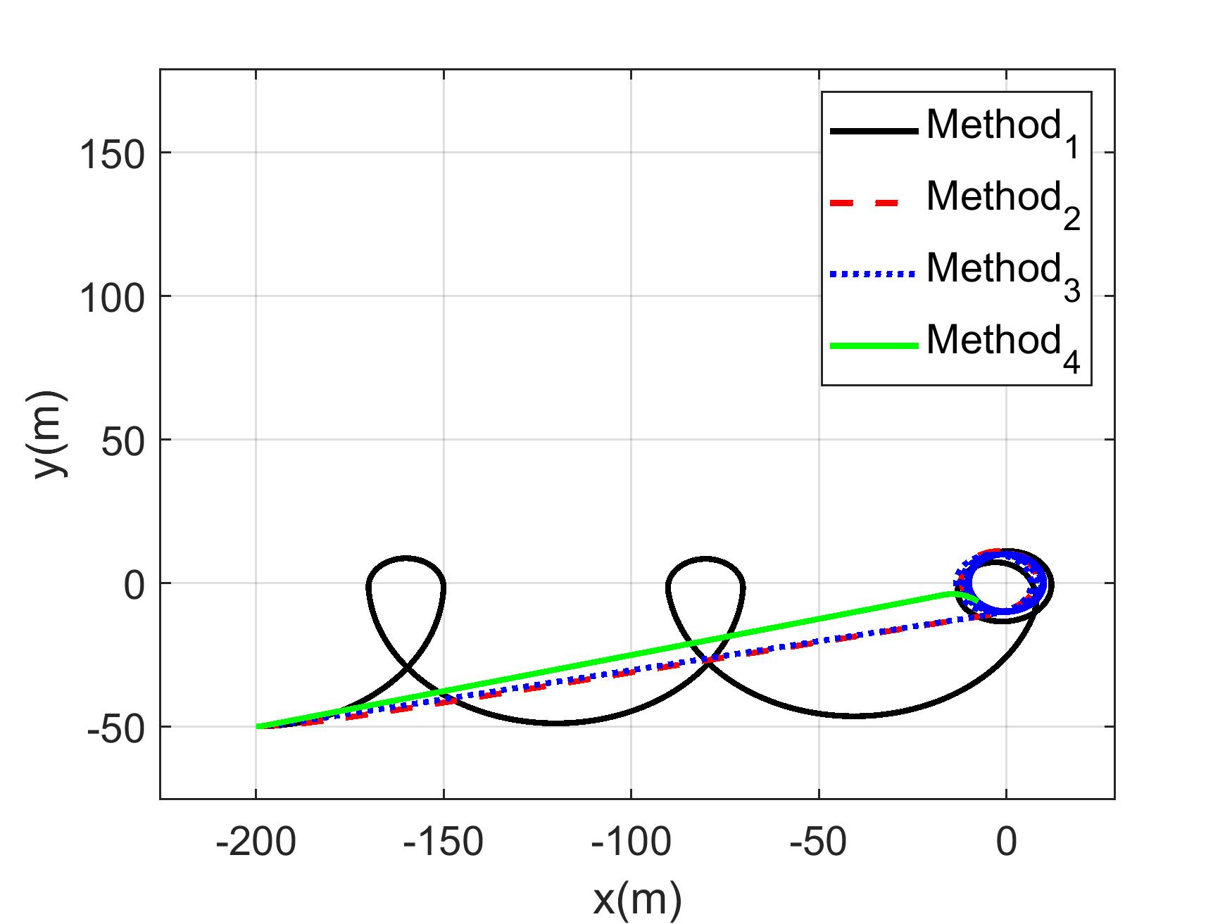
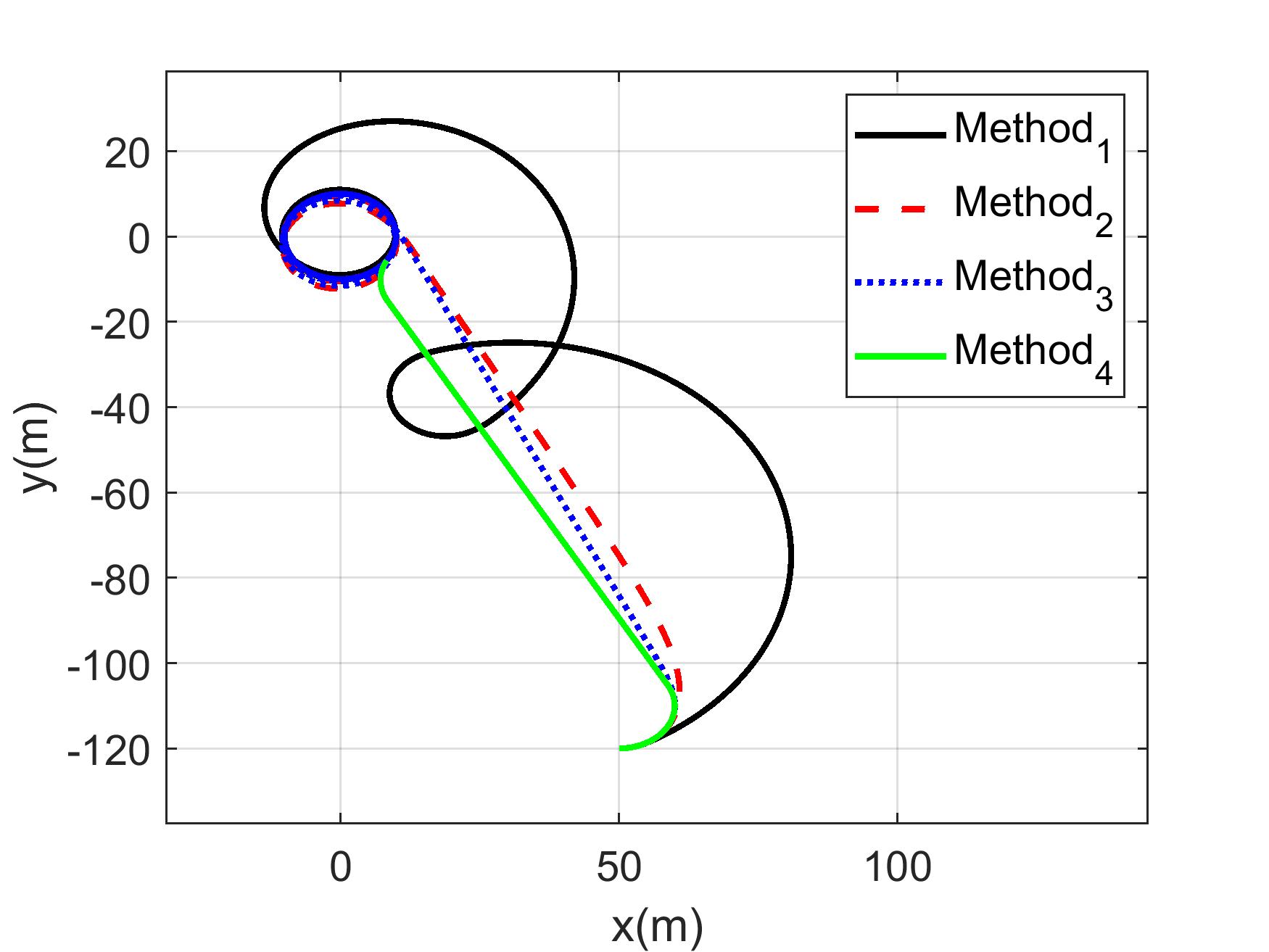
Figure10. ThepathfollowedbytheUAVusingthethree proposedalgorithmsstartingfrom (��0,��0,��0) equalto ��2 =(50��,−120��,0������/��)
controlmethod(������ℎ����1)subjecttocomparisonis theLyapunov‐basedmethodpresentedinSection3.1, thesecondone(������ℎ����2)isthe irstshortersta‐bilizationmethodpresentedinsection 4.1,thethird one(������ℎ����3)isthesecondsimplercomputation stabilizationmethodpresentedinsection4.2andthe fourthmethod(������ℎ����4)isthetime‐optimalmethod presentedinsection3.2.
Multipleinitialconditionsareconsideredinorder toshowtheperformancesofeachmethod.Itshould bementionedthatthecontrolparametersofthe irst methodare ��=0.2������/�� and ��=10��.The parametersofthesecondalgorithmare ��=�������� and ��=10��.Finally,thethirdalgorithmparam‐etersare ��=10 and ��=10��.TheUAVparam‐etersaregivenintable 1,andtheinitialconditions (��0,��0,��0) are ��1 =(−200��,−50��,0������/��) and ��2 =(50��,−120��,0������/��)respectively.
Figure 9 and 10,showthepathfollowedby theUAVstartingfrom(−200��,−50��,0������/��)and (50��,−120��,0������/��)respectively,usingthepro‐posedtrackingcontrolalgorithms.Thethreepro‐posedmethodsareconvergingtowardthehovering pattern.Inthe irstalgorithm(������ℎ����1)thetrajec‐toryusedtogettothe inalpatternistwisting.The secondandthirdalgorithms(������ℎ����2 and������ℎ����3) showtrajectoriesinwhichtheUAVfollowsthetan‐genttowardthehoveringpattern.Thesethreecon‐trolmethodsarecomparedtothetime‐optimaltra‐jectory(������ℎ����4).Table 2 showsthetimeneeded bytheUAVtoreachitscircularhoveringpattern.
������ℎ����1 isshowingverypoorperformancescom‐paredto������ℎ����2,������ℎ����3 and������ℎ����4.Moreover, theoptimalmethodisshowingthebestpossibleper‐formances.������ℎ����2 and������ℎ����3 showverysimilar performances,despitebeingcalculatedindifferent ways,andtheirresultsareverycloseto ������ℎ����4. Finally,itispossibletoassumethatbycarefullychoos‐ingparameter ��(��,��) itispossibletoobtainnearly time‐optimalperformancesusinglesscomputational time.
Insummary,the irstmethodemployedacom‐putationallyef icientalgorithmtoconvergetowards thehoveringpattern.However,itsconvergencetime wasnotablyslow,makingittheleastexpedientamong thefourmethodspresented.Thesecondandthird methodshavecomparableperformance,converging towardsthecircularhoveringpatterninnearlyopti‐maltime.Bothmethodswerecomputationallyef i‐cient,withthesecondmethodbeinglessdemanding thanthethird.Thefourthand inalalgorithmalso successfullyconvergedtowardsthehoveringpattern usinganoptimaltrajectorybutprovedtobecomputa‐tionallydemanding.
Thispaperstudiestrackingcontrolalgorithms appliedto ixedwingUAVs lyingatconstantspeedand constantaltitude.Threecontrolalgorithmsarepre‐sentedforthetrackingofa ixedtarget.Theproposed methodensurestheconvergenceoftheUAVstoward acircularhoveringpattern.
Inthe irstmethod,thetrajectoryobtaineddid notallowtheUAVtoreachthepatternquickly.Inthe secondandthirdmethodpresentedabove,thetrajec‐toriescomputedfollowthedirectionofthetangentto thepattern,whichmakesitpossibletoapproachthe time‐optimalmethodresults.
JeanSawma∗ –FacultyofEngineering,Saint JosephUniversityofBeirut,Beirut,Lebanon,e‐mail: jean.sawma@usj.edu.lb.
AlainAjami –FacultyofEngineering,SaintJoseph UniversityofBeirut,Beirut,Lebanon,e‐mail: alain.ajami@usj.edu.lb.
ThibaultMaillot –Agrosup,Dijon,France,e‐mail: thibault.maillot@agrosupdijon.fr.
JosephelMaalouf –CollegeofEngineeringandTech‐nology,AmericanUniversityoftheMiddle,Kuwait, e‐mail:joseph.el‐maalouf@aum.edu.kw.
∗Correspondingauthor
[1] S.AggarwalandN.Kumar.“Pathplanningtech‐niquesforunmannedaerialvehicles:Areview, solutions,andchallenges,” ComputerCommunications,vol.149,2020,doi:10.1016/j.comcom.2 019.10.014.
[2] A.Ajami,J.‐F.Balmat,J.‐P.Gauthier,andT.Maillot. “Pathplanningandgroundcontrolstationsim‐ulatorforUAV,”In: 2013IEEEAerospaceConference,2013,doi:10.1109/AERO.2013.6496845.
[3] A.Ajami,M.Brouche,J.‐P.Gauthier,and L.Sachelli.“Outputstabilizationofmilitary uavintheunobservablecase.”In: 2020IEEE AerospaceConference,2020,1–6,doi:10.1109/ AERO47225.2020.9172770.
[4] A.Ajami,J.‐P.Gauthier,T.Maillot,andU.Serres. “Howhumans ly,” ESAIM:Control,Optimisation andCalculusofVariations,vol.19,no.4,2013, 1030–1054.
[5] A.Ajami,J.‐P.Gauthier,andL.Sacchelli. “Dynamicoutputstabilizationofcontrol systems:Anunobservablekinematicdrone model,” Automatica,vol.125,2021,109383,doi: 10.1016/j.automatica.2020.109383.
[6] A.Ajami,J.Sawma,andJ.E.Maalouf.“Dynamic stabilization‐basedtrajectoryplanningfor drones,” AIPConferenceProceedings,vol.2570, no.1,2022,020003,doi:10.1063/5.0099757.
[7] A.Balluchi,A.Bicchi,B.Piccoli,andP.Soueres. “Stabilityandrobustnessofoptimalsynthesis forroutetrackingbydubins’vehicles.”In: Proceedingsofthe39thIEEEConferenceonDecisionandControl,vol.1,2000,doi:10.1109/CDC. 2000.912827.
[8] N.BoizotandJ.‐P.Gauthier.“Motionplanningfor kinematicsystems,” IEEETransactionsonAutomaticControl,vol.58,no.6,2013,1430–1442, doi:10.1109/TAC.2012.2232376.
[9] U.BoscainandB.Piccoli. OptimalSynthesesfor ControlSystemson2-DManifolds,Springer,2004.
[10] D.Campolo,L.Schenato,E.Guglielmelli,andS.S. Sastry.“Alyapunov‐basedapproachforthecon‐trolofbiomimeticroboticsystemswithperiodic forcinginputs,” IFACProceedingsVolumes,vol. 38,no.1,2005,637–641.
[11] H.ChitsazandS.M.LaValle.“Time‐optimalpaths foradubinsairplane.”In: 46thIEEEConference onDecisionandControl,2007,2379–2384,doi: 10.1109/CDC.2007.4434966.
[12] L.E.Dubins.“Oncurvesofminimallengthwith aconstraintonaveragecurvatureandwithpre‐scribedinitialandterminalpositionsandtan‐gents,” Am.Journ.Math,vol.79,no.1,1957, 497–516.
[13] E.W.Frew,D.A.Lawrence,C.Dixon,J.Elston, andW.J.Pisano.“Lyapunovguidancevector ieldsforunmannedaircraftapplications.”In: 2007AmericanControlConference,2007,371–376,doi:10.1109/ACC.2007.4282974.
[14] J.‐P.GauthierandV.Zakalyukin.“Onthemotion planningproblem,complexity,entropy,andnon‐holonomicinterpolation,” JournalofDynamical andControlSystems,vol.12,no.3,2006,371–404,doi:10.1007/s10450‐006‐0005‐y.
[15] M.‐D.Hua,T.Hamel,P.Morin,andC.Sam‐son.“Acontrolapproachforthrust‐propelled underactuatedvehiclesanditsapplicationto vtoldrones,” IEEETransactionsonAutomatic Control,vol.54,no.8,2009,1837–1853,doi: 10.1109/TAC.2009.2024569.
[16] M.‐A.Lagache,U.Serres,andV.Andrieu.“Time minimumsynthesisforakinematicdrone model.”In: 54thIEEEConferenceonDecision andControl(CDC),2015,4067–4072,doi: 10.1109/CDC.2015.7402852.
[17] D.A.Lawrence,E.W.Frew,andW.J.Pisano.“Lya‐punovvector ieldsforautonomousunmanned aircraft lightcontrol,” JournalofGuidance,Control,andDynamics,vol.31,no.5,2008,1220–1229,doi:10.2514/1.34896.
[18] T.Maillot,U.Boscain,J.‐P.Gauthier,andU.Ser‐res.“Lyapunovandminimum‐timepathplan‐ningfordrones,” JournalofDynamicaland ControlSystems,vol.21,no.1,2015,47–80,doi: 10.1007/s10883‐014‐9222‐y.
[19] S.Park,J.Deyst,andJ.How.“Anewnonlinear guidancelogicfortrajectorytracking,”2004,doi: 10.2514/6.2004‐4900.
[20] B.PiccoliandH.J.Sussmann.“Regularsynthesis andsuf iciencyconditionsforoptimality,” SIAM J.ControlOptim,vol.39,1998,359–410,doi: 10.1137/S0363012999322031.
[21] Y.Qu,Y.Zhang,andY.Zhang.“Aglobalpathplan‐ningalgorithmfor ixed‐winguavs,” Journalof Intelligent&RoboticSystems,vol.91,no.3,2018, 691–707,doi:10.1007/s10846‐017‐0729‐9.
[22] F.Ropero,P.Muñoz,andM.D.R‐Moreno.“Terra: Apathplanningalgorithmforcooperativeugv–uavexploration,” EngineeringApplicationsof Arti icialIntelligence,vol.78,2019,260–272, doi:10.1016/j.engappai.2018.11.008.
[23] J.Sawma,A.Ajami,andJ.ElMaalouf.“Dynamic stabilityforuavpathplanning.”In: 2022InternationalConferenceonCommunications,Information,ElectronicandEnergySystems(CIEES), 2022,1–6,doi:10.1109/CIEES55704.2022.99 90803.
[24] P.SoueresandJ.‐P.Laumond.“Shortestpaths synthesisforacar‐likerobot,” IEEETransactions onAutomaticControl,vol.41,no.5,1996,672–688,doi:10.1109/9.489204.
Abstract:
DOI:10.14313/JAMRIS/4‐2023/30
Submitted:22nd June2022;accepted:6th March2023
AmalZouhri
Thispaperpresentsanovelapproachtoanalyzingthe robuststabilityofinterconnectedembeddedsystems.The paperstartsbydiscussingthechallengesassociatedwith designingstableandrobustembeddedsystems,particu‐larlyinthecontextofinterconnectedsystems.Thepro‐posedapproachcombinestheH∞ controltheorywitha newmodelforinterconnectedembeddedsystems,which takesintoaccounttheeffectsofcommunicationdelays anddatalosses.Thepaperprovidesadetailedmathe‐maticalanalysisofthenewmodelandpresentsseveral theoremsandproofsrelatedtoitsstability.Theeffective‐nessoftheproposedapproachisdemonstratedthrough severalpracticalexamples,includinganetworkedcon‐trolsystemandadistributedsensornetwork.Thepaper alsodiscussesthelimitationsoftheproposedapproach andsuggestsseveraldirectionsforfutureresearch.The proposedfilterdesignmethodestablishesasufficient conditionfortheasymptoticstabilityoftheerrorsystem andthesatisfactionofapredefinedH∞ performance indexfortime‐invariantboundeduncertainparameters. Thisisachievedthroughtheuseofthestrictlinearmatrix inequalities(LMI)approachandprojectionlemma.The designisformulatedintermsoflinearmatrixinequalities (LMI).Numericalexamplesareprovidedtodemonstrate theeffectivenessoftheproposedfilterdesignmethods.
Keywords: Interconnectedembeddedsystems,Stability, H∞ analysis,Linearmatrixinequalities
Interconnectedembeddedsystemsarewidely usedinmanyapplicationdomains,suchasaerospace, automotive,andindustrialautomation.Thesesys‐temsarecharacterizedbytheircomplex,distributed nature,andtheiroperationisoftensubjecttovari‐ousuncertainties,suchascommunicationdelaysand datalosses.Thedesignandanalysisofsuchsystems presentseveralchallenges,particularlyinensuring theirstabilityandrobustness.
Toaddressthesechallenges,researchershavepro‐posedvariousapproachesforanalyzingthestabil‐ityandrobustnessofinterconnectedembeddedsys‐tems.Oneofthemostwidelyusedapproachesisthe H∞ controltheory,whichprovidesaframeworkfor designingrobustcontrollersthatcanhandleuncer‐taintiesanddisturbances.
Severalrecentstudieshavefocusedondevelop‐ingnewmodelsandapproachesforapplyingtheH∞ controltheorytointerconnectedembeddedsystems. Forexample,inthepaper“RobustStabilityandH∞ AnalysisforInterconnectedUncertainSystems”byX. Zhangetal.(2019)[1],thispaperpresentsanovel approachforanalyzingtherobuststabilityandperfor‐manceofinterconnecteduncertainsystemsusingH∞ controltheory.Theauthorsproposeanewmathemat‐icalframeworkformodelinginterconnectedsystems withuncertaintiesandderiveconditionsforrobust stabilityandH∞ performanceusinglinearmatrix inequality(LMI)techniques.Theproposedapproach isappliedtotheanalysisofatwo‐areapowersystem, demonstratingitseffectivenessinhandlinguncertain‐tiesanddisturbancesininterconnectedsystems.The paperalsodiscussesthepotentialapplicationsofthe proposedapproachinother ields,suchastransporta‐tionandcommunicationsystems.Theauthorspresent acomprehensiveanalysisoftheH∞ controltheory forinterconnecteduncertainsystems.Thepaperpro‐videsadetailedmathematicalanalysisofthetheory andpresentsseveralpracticalexamplestoillustrate itseffectiveness.
H∞ controltheoryisarobustcontrolmethodol‐ogythathasbeenusedinvarious ields,including aerospace,automotive,andcontrolsystemsengineer‐ing.Itprovidesasystematicapproachfordesigning controllersthatcanhandleuncertaintyanddistur‐bancesinasystem,whilealsomeetingperformance speci ications.
Inthecontextofinterconnectedembeddedsys‐tems,H∞controltheorycanbeappliedtoensurethat thesystemoperatesreliablyandef iciently,despite thepresenceofuncertaintiesanddisturbances.Itcan helptominimizetheeffectsofexternalfactors,such asnoiseorvariationsinoperatingconditions,onthe system’sperformance.
ResearchhasshownthatH∞ controltheorycan beeffectiveinaddressingvariouschallengesininter‐connectedembeddedsystems.Forexample,ithas beenappliedinthedesignofcontrolsystemsfor autonomousvehicles,wherethecontrolsystemmust beabletohandleuncertaintiesinthevehicle’senvi‐ronment,suchasunpredictabletraf icpatternsand roadconditions.
Anotherexampleisinthedesignofcontrolsys‐temsforindustrialautomation,whereH∞ control theoryhasbeenusedtoensurethatthesystem canhandlevariationsinproductionprocessesand equipmentperformance,whilealsomeetingperfor‐mancespeci ications.
Anotherrecentstudy,“RobustModelPredictive ControlofInterconnectedEmbeddedSystemsSub‐jecttoCommunicationDelays”byM.Osmanetal. (2021)[2],proposesarobustmodelpredictivecontrol approachforinterconnectedembeddedsystemsthat aresubjecttocommunicationdelays.Theproposed approachtakesintoaccounttheeffectsofcommu‐nicationdelaysonthesystem’sstabilityanduses. Thispaperproposesarobustmodelpredictivecontrol approachforinterconnectedembeddedsystemssub‐jecttocommunicationdelays.Theauthorsconsider anetworkedcontrolsystemconsistingofmultiple interconnectedsubsystems,eachwithitsownembed‐dedcontrollerandsensor/actuatornetwork.They proposeapredictivecontrolschemethataccounts forthecommunicationdelaysanduncertaintiesin thesystem,usingarobustoptimizationframework basedonmixed‐integerlinearprogramming(MILP). Theproposedapproachisappliedtothecontrolof atwo‐tanksystem,demonstratingitseffectivenessin handlingcommunicationdelaysanduncertaintiesin interconnectedembeddedsystems.Thepaperalso discussesthepotentialapplicationsoftheproposed approachinother ields,suchasindustrialautomation andsmartgridsystems.
Thepaper“Robuststabilityanalysisandfeed‐backcontrolfornetworkedcontrolsystemswithaddi‐tiveuncertaintiesandsignalcommunicationdelay viamatricestransformationinformationmethod”by Weietal.(2022)[3]presentsanovelapproachfor analyzingthestabilityandrobustnessofintercon‐nectedembeddedsystems.Theproposedapproach combinestheH∞ controltheorywithanewmodel thattakesintoaccounttheeffectsofcommunica‐tiondelaysanddatalosses.Thepaperprovidesa detailedmathematicalanalysisofthenewmodeland demonstratesitseffectivenessthroughseveralpracti‐calexamples.Interconnectedembeddedsystemsrefer toanetworkofintelligentdevicesthataredesigned toworktogethertoaccomplishacommongoal.These systemsaremadeupofsmall,specializedcomputers thatareembeddedinotherdevices,suchasappli‐ances,vehicles,andindustrialequipment.Theycom‐municatewitheachotherandwiththeoutsideworld usingvariousprotocols,suchasBluetooth,Wi‐Fi,and Zigbee.
Interconnectedembeddedsystemsarebecoming increasinglyimportantasmoredevicesbecomecon‐nectedtotheinternetandtheInternetofThings(IoT) continuestogrow[4–7].Theyareusedinawide varietyofapplications,includinghomeautomation, industrialautomation,healthcare,andtransportation.
Oneofthekeyadvantagesofinterconnected embeddedsystemsistheirabilitytoshareinformation andresources[8–12],allowingthemtoworktogether moreef icientlyandeffectively.
Forexample,asmarthomesystemmightusesen‐sorsandactuatorstocontrolthetemperature,light‐ing,andsecurityofahouse,allwhilesharingdatawith othersystemsinthehome.
However,interconnectedembeddedsystemsalso presentnewchallenges,suchassecurityandprivacy concerns,compatibilityissuesbetweendevicesand systems,andtheneedforreliableandrobustcom‐municationprotocols.Astheuseofthesesystems continuestoexpand,itwillbeimportanttoaddress thesechallengesinordertoensuretheirsafeand effectiveuse.
ThestabilityandH∞ analysisforinterconnected embeddedsystemsisaninterestingandcomplexarea ofresearch,whichhasasigni icantimpactonthe designandimplementationofmodernembeddedsys‐tems.
Inthecontextofinterconnectedembeddedsys‐tems,thestabilityoftheoverallsystemiscritically dependentonthestabilityofeachindividualsubsys‐tem.Asaresult,itisessentialtounderstandtheinter‐actionsbetweenthesubsystemsandtoensurethatthe overallsystemdesignisstable.
Onechallengeinanalyzingthestabilityofinter‐connectedembeddedsystemsisthepresenceof delaysandothercommunicationissues.Thesedelays canhaveasigni icantimpactonthestabilityofthe system,anditisimportanttoaccountforthemwhen designingthesystemandanalyzingitsstability.
Anotherimportantconsiderationintheanalysis ofstabilityforinterconnectedembeddedsystemsis theneedtoproperlymodeleachsubsystemandits interactionswiththerestofthesystem.Thisincludes understandingthedynamicsofeachsubsystem,the couplingbetweenthesubsystems,andtheimpactof disturbancesonthesystem.
Inordertoanalyzethestabilityofinterconnected embeddedsystems,H∞ analysisisoftenused.This approachinvolvesmodelingthesystemasasetof matricesandusingoptimizationtechniquesto indthe optimalcontrolstrategythatminimizestheimpactof disturbancesonthesystem.Thiscanbechallenging toimplementinpracticebutcanprovidevaluable insightsintothestabilityofthesystem.
Overall,thestabilityandH∞ analysisforinter‐connectedembeddedsystemsisanimportantarea ofresearch[13–24],whichhassigni icantimplica‐tionsforthedesignandimplementationofmodern embeddedsystems.Itisacomplexarea,butadvances inthis ieldareessentialforensuringthestabil‐ityandreliabilityofthesesystemsinavarietyof applications.
Overall,thesestudiesdemonstratetheimpor‐tanceofdevelopingnewmodelsandapproachesfor analyzingthestabilityandrobustnessofintercon‐nectedembeddedsystems.Theseapproachescanhelp ensurethesafeandreliableoperationofsuchsys‐temsinvariousapplicationdomains.Insection 2, anoverviewofSystemModelshasbeenprovided. Performanceanalysisoflinearuncertainsystemshas beenintroducedinsection3.Insection4,wepresent numericalexamplestoshowtheusefulnessofthe
proposedresults.Finally,thepaperendswiththebrief conclusioninsection5
Weconsiderthefollowinginterconnectedembed‐deduncertainsystemsshowninFigure 1,wherethe ����ℎsubsystemisgivenby[25]
��(��)=��������(��)+ ���� ��=1 ����������(��)+������(��)
����(��)=����Δ����(��)+Φ��Δ����(��) (1) andwhere���� ∈ℜ�� isthestatevectorofsubsystemj, theexogenousinput���� ∈ℜ��1 representsdisturbance signals, ���� ∈ℜ��1 isthecontrolledoutput, ��,��∈ {1,…,����},andthematrices ����Δ, ������Δ, Γ��Δ, ����Δ,and Φ��Δ areofappropriatedimensions.Todescribethe uncertainty,thesystemmatrices����,������,Γ��,����,andΦ�� areassumedtobeuncertain,belongingtoaconvex polytopicmodelofthetype.
����Δ ������Δ Γ��Δ
����Δ 0Φ��Δ ∈Π�� ≜ ������ �������� Γ���� ������ 0Φ����
�� ��=1 ���� ������ �������� Γ���� ������ 0Φ���� , ���� ∈Λ�� (2)
Where Λ�� ≜
1,…,����)∶ �� ��=1 ���� =1,����
���� =��������(������),�� =��������(����),
��=[���� 1,…,���� ����]��,��=[���� 1,…,���� ����]�� (5)
Consideringthesystem(4),thetransferfunctionfrom ��(��)to��(��)isgivenby
����(��)=����(����−����)−1Γ�� +Φ�� (6)
Thesystem(4)satis iestheHin inityattenuation criterionif,forallnonzero��(��)∈���� 2[0,∞)
������ ‖��(��)‖2≠0
‖��(��)‖2 ‖��(��)‖2 ≤�� (7)
Foraprescribedscalar��≻0,where‖⋅‖2 stands forthe��2 norm.
Asshownin[26,27],condition(7)issatis iedif: ��(��)+����(��)��(��)−��2����(��)��(��)≺0 (8)
Remark1.Theparameteruncertaintiesconsidered inthispaperareassumedtobeofpolytopictype. Thepolytopicuncertaintyhasbeenwidelyusedin theproblemsofperformanceanalysisforuncertain systems.
First,lemma1and2,whicharegiven,arevery essentialforthenextdevelopments.
Thefollowinglemmaprovidesanecessaryand suf icientconditionforthesystem(4)tobestablewith ‖��(��)‖∞ ≺��
(3)
Where��={1,…,��}isnumberofpolytopevertices. Theclassofsystemsdescribedby(1)isfrequently encounteredinmodelingseveralphysicalsystems. Thesubsystemsinformula(1)canbereformuledas �� = ���� Γ�� ���� Φ��
With ����
�� �� (4)
��1�� ��12�� …��1������ ��21�� ��2�� …��2������ ⋮⋮⋱⋮ ������1�� ������2�� ⋯�������� ,Γ�� =��������(Γ����),
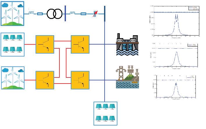
Lemma1[9, 18].TheContinuous‐timesystem(4), withpolytopicrepresentation(2)–(3),isasymptoti‐callystablewith‖��(��)‖∞ ≺��,forall��∈Λ��,ifand onlyifthereexistsamatrixfunction���� ≻0andscalar ��≻0,suchthatthefollowingLMIhold(thesymbol∗ meansasymmetricblock):
�� (9)
Lemma2[13](Finsler’sLemma).Let ��∈ℜ�� , ��= ���� ∈ℜ��×��and ��∈ℜ��×�� suchthat ��������(��)≺��, and��⊥ abasisforthenull‐spaceof�� (i.e.��⊥��=0). Thenthefollowingstatementsareequivalent:
1) ��������≺0,forall��≠0,����=0;
2) ���� ⊥����⊥ ≺0;
3) ∃��∈ℜ��×�� ∶��+����+�������� ≺0
Inthissection,wepresentastabilityandH∞per‐formanceofinterconnecteduncertainsystems.
Inthissection,anewrobuststabilityconditionsfor thepolytopicembeddedsystem(4)isdeveloped.The mainresultforuncertainembeddedsystemisstated inthefollowingtheoremwith��(��)≡0.
Theorem1.Thepolytopicembeddedsystem(4)is asymptoticallystable,forall��∈Λ��,ifandonlyifthere existsmatrices���� ≻0,��,�� and��≺0suchthatthe followingLMIsarefeasible.
������ +���� ������ −�������� −��+���� ������
∗ −��−���� −���� ≺0, (10)
Proof
TheLMIs(10)areobtainedbyconsidering
��= �� �� , (11)
��= ���� −�� , (12)
��= 0���� ���� 0 , (13) incondition(3)ofLemma2,with
��⊥ = �� ���� (14)
Theorem2.Theuncertainembeddedsystem(4) isasymptoticallystablewith ‖��(��)‖∞ ≺��,for all��∈Λ��,ifandonlyifthereexistsmatrices ���� ≻ 0,��1,��2,��3,and��4,suchthatthefollowingLMIsare feasible.
Ψ
∗Ψ
∗∗Ψ33 Ψ34
∗∗∗−��
Where
2
≺0, (15)
Ψ13 =��1Γ�� +���� ������ 3
Ψ14 =���� �� +���� ������ 4
Ψ22 =−��2 −���� 2
Ψ23 =��2Γ�� −���� 3
Ψ24 =−���� 4
Ψ33 =−��2��+��3Γ�� +Γ�� �� ���� 3
Ψ34 =Φ�� �� +Γ�� �� ���� 4 (16)
Proof
Choosealyapunovfunctioncandidatetobe ��(��)=����(��)������(��) (17)
���� givenby ���� = ∑�� ��=1 ��������,where ������ ∈ℜ��×�� are constantsymetricmatricesmustbedetermined.
Calculatingthederivativeof ��(��) from(8),we obtained
��(��)����(��)+����(��)��̇��(��)+����(��)��(��)−��2����(��)��(��)
0���� 0���� �� ∗000 ∗∗−��2��Φ�� �� ∗∗∗−��
��= ⎡ ⎢ ⎢ ⎣ ��1 ��2 ��3 ��4 ⎤ ⎥ ⎥ ⎦ , (21) ��= ���� −��Γ�� 0 , (22)
��⊥ = ⎡ ⎢ ⎢ ⎣ ��00 ���� Γ�� 0 0��0 00�� ⎤ ⎥ ⎥ ⎦ (23)
whichprovides,bycalculationandusingcondition(ii) oflemma2,theequalitybetween ���� ⊥����⊥ ≺0 and theLMIsin(9).Thus,(9)isequivalentto(15)using Lemma2.
Thiscompletestheproofofthetheorem2.
4.NumericalExample
1(��)=��1����1(��)+ 3 ��=1,��≠1 ��1��������(��)+Γ1����1(��) ��1(��)=��1����1(��)+Φ1����1(��) Subsystem2: 2(��)=��2����2(��)+ 3 ��=1,��≠2 ��2��������(��)+Γ2����2(��) ��2(��)=��2����2(��)+Φ2����2(��) Subsystem3: 3(��)=��3����3(��)+ 3 ��=1,��≠3 ��3��������(��)+Γ3����3(��) ��3(��)=��3����3(��)+Φ3����3(��) 52
Table1. ComparisonofMinimumH∞ performance, ��min
Method
SchuleforDecentralizedstate feedbackcontrolforinterconnected systemsin[9]
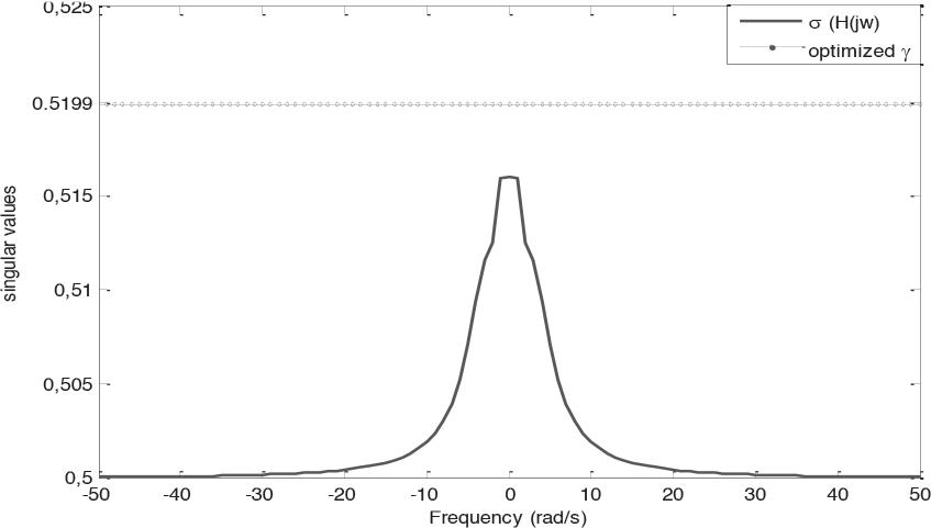
Figure2. Interconnectedembeddedsystem:firstvertex
Withthefollowingparameters:
,��32�� = 00 0−1 , AccordingtoLemma1andTheorem2,theobtained guaranteedperformancesarelistedinTable1
Table1showsclearlythatLemma1islessconser‐vativethanTheorem2forthisexample.
Fortheanalysisofinterconnectedembeddedsys‐tems,theH∞normscomputedatthefourverticesof interconnectedembeddedsystemareobtainedfrom theFigures 2 to 5:alltheobtainednormsunderthe guaranteedthe0.5199bound.
TheconclusionofthestudyonstabilityandH∞ analysisforinterconnectedembeddedsystemsisthat itiscriticaltoconsiderthestabilityoftheover‐allsystemwhendesigninginterconnectedembedded systems.
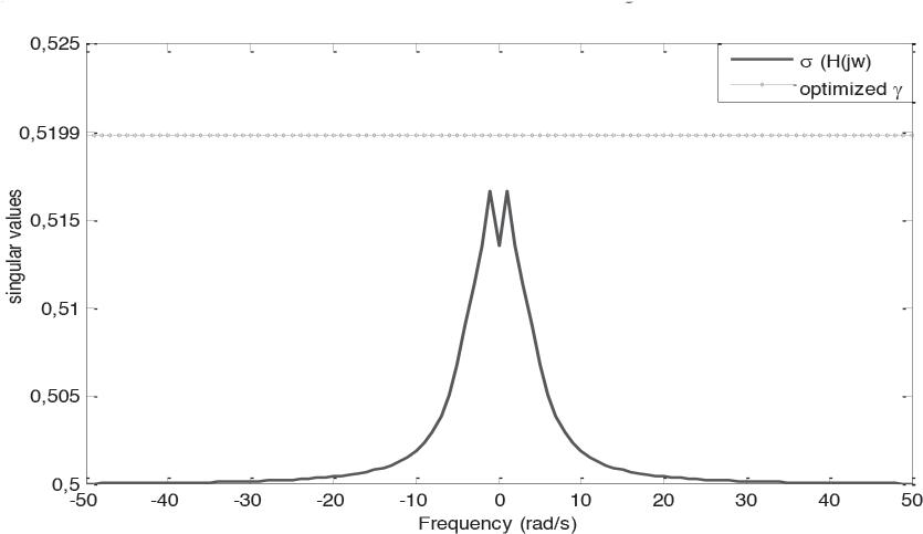
Interconnectedembeddedsystem:second vertex
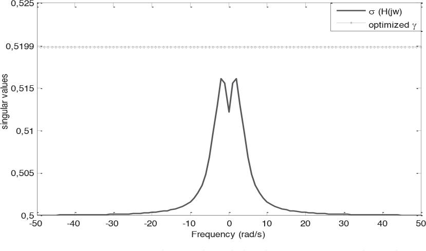
Interconnectedembeddedsystem:thirdvertex

Interconnectedembeddedsystem:fourth vertex
Theinterconnectionofmultiplesubsystemscan leadtoinstabilityandthepossibilityofsystemfailure, whichcanhaveseriousconsequencesinsafety‐critical applicationssuchasautomotiveoraerospacesystems. H∞ controltheoryprovidesapowerfulframework fordesigningrobustcontrolsystemsthatcanmiti‐gatetheeffectsofdisturbancesanduncertainties.By usingH∞ controltechniques,itispossibletodesign controllersthatguaranteestabilityandperformance despiteuncertainorunknownsystemparameters. Thestudyhighlightstheimportanceofconsidering theinterconnectionstructureofembeddedsystems whenapplyingH∞ controltechniques.Inparticular, thestudyemphasizestheneedtoaccountforthecou‐plingbetweendifferentsubsystemsandtheeffectof externaldisturbancesonthesystem.
Overall,thestudyconcludesthattheuseofH∞ controltechniquescansigni icantlyimprovethesta‐bilityandperformanceofinterconnectedembed‐dedsystems,anditisessentialtoconsiderthese techniquesinthedesignofsafety‐criticalembedded systems.
AUTHOR
AmalZouhri∗ –SidiMohammedBenAbdellahUni‐versity,FacultyofSciencesDharElMahraz,Fez, Morocco,e‐mail:amal.zouhri@usmba.ac.ma.
∗Correspondingauthor
References
[1] X.Zhang,X.Liu,G.Yang,andY.Zou.“Robuststa‐bilityandH∞analysisforinterconnecteduncer‐tainsystems,” IEEETransactionsonIndustrial Electronics,vol.66,no.9,2019,pp.6911–6920. doi:10.1109/TIE.2018.2889317
[2] M.Osman,S.Wang,andK.Tang.“Robustmodel predictivecontrolofinterconnectedembedded systemssubjecttocommunicationdelays,” IEEETransactionsonIndustrialElectronics, vol.68,no.3,2021,pp.1893–1903.doi: 10.1109/TIE.2020.2968401
[3] W.Zheng,Z.Zhang,F.Sun,andS.Wen.“Robust stabilityanalysisandfeedbackcontrolfornet‐workedcontrolsystemswithadditiveuncertain‐tiesandsignalcommunicationdelayviamatri‐cestransformationinformationmethod,” InformationSciences,vol.582,pp.258–286,Jan.2022, doi:10.1016/j.ins.2021.09.005.
[4] Z.Wang,G.Feng,H.R.Karimi,andX.Zhao. “RobustH∞ controlforuncertainswitched delayedsystemswithtime‐varyingdelayand inputsaturation,” IEEETransactionsonCircuits andSystemsII:ExpressBriefs,vol.64,no.5,2017, pp.547–551.doi:10.1109/TCSII.2016.2537570.
[5] Y.Hong,andY.Q.Chen.“RobustH∞ iltering fortime‐delaysystemswithsensorfaultsand packetdropouts,” IEEETransactionsonCybernetics,vol.49,no.9,2019,pp.3171–3181.doi: 10.1109/TCYB.2018.2867895.
[6] X.Zhang,J.Chen,andX.Li.“RobustH∞ controlofuncertaint‐sfuzzysystemswith time‐varyingdelayviaswitchedlyapunov functionals,” IEEETransactionsonFuzzy Systems,vol.27,no.8,2019,pp.1577–1589.doi: 10.1109/TFUZZ.2018.2877014.
[7] Z.WangandG.Feng.“Delay‐dependentH∞con‐trolofswitchedsystemswithtime‐varyingdelay andactuatorsaturation,” IEEETransactionson IndustrialElectronics,vol.66,no.3,2019,pp. 2178–2186.doi:10.1109/TIE.2018.2827393.
[8] Z.G.WuandT.Chu.“H∞ controlforaclass ofdiscrete‐timeswitchednonlinearsystems withtime‐delayandactuatorsaturation,”
IEEETransactionsonIndustrialElectronics, vol.67,no.3,2020,pp.1968–1976.doi: 10.1109/TIE.2019.2905538.
[9] S.Schuler,U.Münz,andF.Allgöwer.“Decentral‐izedstatefeedbackcontrolforinterconnected systemswithapplicationtopowersystems,” JournalofProcessControl,vol.24,2014,pp. 379–388.
[10] H.Li,H.Gao,andJ.Lam.“H∞ ilteringfor switchedlinearsystemswithsensorfaultsand packetdropouts,” IEEETransactionsonCircuits andSystemsII:ExpressBriefs,vol.64,no.4,2017, pp.443–447.doi:10.1109/TCSII.2016.2562325.
[11] G.FengandC.Yang.“H∞ controlofswitched linearsystemswithtime‐varyingdelayand inputsaturation,” IEEETransactionsonAutomaticControl,vol.65,no.4,pp.1779–1786.doi: 10.1109/TAC.2019.2926787.
[12] H.Gao,T.Chen,andJ.Lam.“H∞ stateestima‐tionforswitchedlinearsystemswithsensor faultsandpacketdropouts,” IEEETransactions onIndustrialElectronics,vol.65,no.6,2018,pp. 5006–5016.doi:10.1109/TIE.2017.2771919.
[13] Z.Wang,andG.Feng.“RobustH∞ controlfor uncertainswitchedsystemswithtime‐varying delayandinputsaturation,” IEEETransactions onAutomaticControl,vol.63,no.12,2018,pp. 4227–4234.doi:10.1109/TAC.2018.2821039.
[14] Y.XuandM.Fu.“Robuststabilityandstabiliza‐tionofswitchedinterconnectedsystems:asur‐vey,” IEEETransactionsonAutomaticControl,vol. 66,no.8,2021,pp.3552–3569.
[15] T.ChenandB.Francis.“Robustcontrolofuncer‐taininterconnectedsystems:asurvey,” IEEE TransactionsonControlofNetworkSystems,vol. 7,no.4,pp.1408–1420.
[16] Y.YangandY.Zhang.“RobustH∞ controlfora classofnonlinearinterconnectedsystems,” IEEE TransactionsonAutomaticControl,vol.66,no.3, 2020,pp.1278–1285.
[17] X.GuoandB.Jiang.“Robuststabilizationofinter‐connectedsystemsviadynamicoutputfeed‐back,” Automatica, vol.103,2019,pp.23–31.
[18] Y.MaandJ.Huang.“RobustH∞ controlfora classofnonlinearinterconnectedsystemswith uncertainties,” IEEETransactionsonCircuitsand SystemsII:ExpressBriefs,vol.66,no.3,2019,pp. 500–504.
[19] M.LiandZ.Zhang.“Robuststabilizationofinter‐connectedsystemswithtime‐varyingdelaysvia outputfeedback,” IEEETransactionsonCircuits andSystemsII:ExpressBriefs,vol.65,no.8,2018, pp.1055–1059.
[20] Y.XuandJ.Zhang.“Robuststabilizationofaclass ofuncertaininterconnectedsystemsviafuzzy control,” IEEETransactionsonFuzzySystems,vol. 26,no.2,2018,pp.789–798.
[21] Y.ZhangandT.Hu.“RobustH∞controlforinter‐connectedsystemswithtime‐varyingdelays,” IEEETransactionsonAutomaticControl,vol.62, no.7,2017,pp.3655–3662.
[22] C.PengandY.Du“RobustH∞controlforaclass ofnonlinearinterconnectedsystemswithtime‐varyingdelay,” NonlinearDynamics,vol.88,no.3, 2017,pp.1783–1793.
[23] S.LiandH.Li.“Robuststabilizationofintercon‐nectedsystemsviafuzzycontrol,” IEEETransactionsonCybernetics,vol.46,no.7,2016,pp. 1656–1667.
[24] X.WangandY.Du“RobustH∞ controlfora classofnonlinearinterconnectedsystemswith parametricuncertainties,” IETControlTheory& Applications,vol.10,no.3,pp.203–210.
[25] L.LiuandT.Chen.“Robuststabilizationofinter‐connectedsystemswithstate‐dependentuncer‐tainties,” Automatica, vol.69,2016,pp.36–43.
[26] X.ZhangandY.Zhang.“RobustH∞ control forinterconnectedsystemswithtime‐varying delaysandpacketdropouts,” IEEETransactions onIndustrialElectronics,vol.62,no.8,2015,pp. 5067–5074.
[27] X.Wang&Y.Du.“RobustH∞ controlforaclass ofnonlinearinterconnectedsystemswithtime‐varyingdelays,” IETControlTheory&Applications,vol.9,no.14,pp.2131–2138.
[28] J.Wang,andY.Li.“Robuststabilizationof interconnectedsystemswithuncertaintime‐varyingdelaysviaslidingmodecontrol,” NonlinearDynamics,82(4),pp.2129–2140.
Abstract:
Submitted:22nd December2022;accepted:27th February2023
MubeenAhmedKhan,AwanitKumar,KailashChandraBandhu
DOI:10.14313/JAMRIS/4‐2023/31
InternetconnectivityinWiMAXnetworks,alongwithvar‐iousapplications,isincreasingrapidly,sotheconnectivity ofinternetanddatatransferspeedarealwayschallenges foreffectivedatatransmissioninwirelessnetworks.Sev‐eralfactorsaffecttheperformanceofnetworks.One importantfactoristochooseasuitableframeperiodfor effectivedatatransmissions.Theperformanceofdiffer‐entframeperiodswithRoundRobinandStrictPriorityis evaluatedinthiswork.AframeperiodinRoundRobin performsbetterthanaStrictPriorityintermsofthrough‐put,butaStrictPriorityperformsbetterintermsofdrop rates.Thispaperalsodemonstratesthataneffective frameperiod,whencombinedwithaproperbandwidth allocationalgorithm,yieldsbetterresults.Thisworkgives theanalysisthatRoundRobinperforms83.8847%bet‐terwhileStrictPriorityperforms86.0020%betterthan theearliestdeadlinefirstalgorithmsfor10subscriber stationsintermsofthroughput.Thisworkishelpfulto researchersandindustrialistsforactualimplementations inWiMAXnetworks.
Keywords: IEEE802.16,WiMAX,Bandwidthallocation algorithm,Frameperiod,Roundrobinalgorithm,Strict priorityalgorithm
TheWiMAXisakindofBroadbandWirelessAccess (BWA)networkforhigh‐speeddatatransferthatcan beusedwherethelyingofcablesisnotfeasible[1]. Varioustechnologieshavebeendesignedbasedon IEEEstandards.ItincludesIEEE802.11forWi‐Fi, IEEE802.16‐2004for ixedWiMAX,andIEEE802.16e formobileWiMAX.ItisaBWAsystemthatfollows theIEEE802.16‐2004andIEEE802.16estandards[2]. Wirelessservicesarechallenginginrural,denseareas, andsometimes,inunevengeographicalareas,there arehighdataratesinWiMAXnetworkswithlargecov‐erageareasandalargefrequencyspectrumforinte‐gratedvideo,audiovoice,anddataservicesrequired inthoseareas.Networkenhancementandperfor‐manceimprovementarestillachallengeinmobile WiMAXnetworks.Inreal‐lifescenarios,packetsare droppedwhileusingthequalityofservices(QoS)such asaudio,video,orvoice.Thedroppingofpackets usingtheexistingtechniqueaffectssystemperfor‐manceduetovariousfactors,suchasinfrastructure, environments,andappliedalgorithms.
Thisworkisbasedontheappliedalgorithmin whichtheperformanceofthesystemisaffected.The performanceoftheproposedsystemisincreased byoptimizingtheframeperiods.Theframedura‐tion,alongwiththechannelbandwidthalgorithm, isanimportantareatoenhancetheperformanceof WiMAXnetworksinrural,dense,andunevengeo‐graphicalareasfordifferentdataservices.Thecur‐rentimplementationsaredoneusingabasestation andsubscriberstationsforaudio,video,anddataser‐vicesinfourth‐generationtechniques.Theconnectiv‐itybetweentheSSsandBSfordatatransferisdone usingindividualTransmissionControlProtocol(TCP) connectionsandsynchronization,whichisamustfor transmissionofdata[3].AllSSsreceivedatafrom thebasestationatthestartofeveryframeusingan UplinkMap(ULMAP)message[4].TheLightWiMAX usestheprincipleoforthogonalfrequencydivision multiplexingandprovidesvariousqualitiesofservice andmultihoppingtechniques[5].
Thisworkalsofoundthattheexistingframeperiod isnotatpeakef iciencyanddemonstratesbetter results.Whenvaryingtheframeperiodsintheexisting algorithm,optimizednewframeperiodintheexisting algorithmgivesbetterresults.
Thenextsectionsofthispaperincludethelit‐eraturesurveywithnetworkstructure,followedby bandwidthallocationalgorithms,thenresultsanddis‐cussions,and inallytheconclusionandfuturework.
Hugeworkhasbeendoneinwirelesscommunica‐tionsystemsinscheduling,buttherearestillvarious needstobedoneforeffectiveperformanceinWiMAX networks.Previousworkhasbeendoneonvarious algorithmslikeRoundRobin[6],WeightedRound Robin[7,8],andWeightedFairQueuing[9],whichare generallyproposedforWiMAXnetworks.Thesealgo‐rithmsaregeneralalgorithmsanddonottakecareof speci icapplicationsofWiMAXnetworks.Thesealgo‐rithmsarenoteffectiveforhigh‐speeddatanetworks butarestillusedinmanyapplicationsofWiMAXnet‐works.Somewirelessapplicationsarechannelaware applications,whilesomealgorithmsarenon‐aware ofchannelbandwidth.Someoftheprede inedalgo‐rithmsarestillnotsuitableforhigh‐speedinternet services,whilesomealgorithmsarenotsuitablefor mobilityapplications.Whenchannelawareschemes arediscussed,itisrequiredtounderstandchannel stateinformation.
Priorityisgiventothosesubscriberstationswhose channelconditionsaregood.Also,ifchannelcon‐ditionsaregoodandproperallocationtechniques likeradioresourcesandutilizationareavailable,it becomeseasytoenhancetheperformanceofnet‐works.Theissuewiththeseschemesisintheallo‐cationtechniques,inwhichsubscriberstationsstarve forsubstantialintervalsifchannelconditionsarepoor, whileoverprovisionsaremadeforSSswithgood channelconditions.MAClayerschemesaredesigned withidealchannelconditionsinmind.Thepurposeof MAClayerschemesistoassuremaximumthroughput, minimumtraf icrate,andfairness.SincevariousQoS classesarede inedinWiMAXnetworkswithdifferent requirements,animportantschedulingdecisionmust imposesomesortofpriority.Multiantennamode andavailablebandwidthareresponsibleforhigh‐speeddatatransferratesovertheairofabout1Gbps speed.Thistypeofworkissuitableforgoodquality andhighercapacityservicesandinternetprotocols suitableforavastrangeandquality‐basedinternet services.Theseservicesarenotonlysuf icientto maintainfullbackwardcompatibilitybutalsosupport thoseservicesthatmaybeusefulfornext‐generation internetservices.Thisworkmentionedallthetechni‐calaspectsofIEEE802.16minwhichnext‐generation internetservicesareproposedinthefuture[10].
Forfullutilizationofframes,mobileWiMAX allowspacketfragmentation,whichenhancesnet‐workcapacity.Variationsinchannelconditionscause variationsintimeandlocation.De icitroundrobin withfragmentationandtheearliestdeadline irst algorithmsaresomealgorithmsthatwerepreviously proposed.Resourcesareallocatedasperthevaria‐tioninlinkcapacityinmobileWiMAXinaneffec‐tivemannertotransmitfragmentedpacketsinthe network[11].De icitroundrobinwithfragmenta‐tiongivesbetterperformanceintermsofthrough‐putthanDRR,whichisabout80%higher,giving minimumoverheadsthanglobalpositioningsystems. Someworkhasalsobeendoneonframedura‐tionstoimprovetheperformanceenhancementsof WiMAXnetworks.Thispaperconsidersdataratein termsofspectralef iciencies,cellcoverage,latencies, spectrumef iciency,andqualityofservice,includ‐ingcomplexities.Thispaperexplorestheimproved WiMAXtechnologyfocusingonthephysicallayer, MAClayer,andthoseservicesessentialtoimprove qualityofservicesfornetworkbetterments[12].This workfocusesondetailedschedulingandcollaboration withserviceproviders.Channelawarenesscross‐layer schedulingisproposed,whichdescribesthereduction ofpacketlossanddelayandgivesbetterthrough‐put[13].Thispaperdetailsthetransmissioncontrol protocolanduserdatagramprotocolperformancein IEEE802.16[14].Inthiswork,theauthordiscusses andanalysesissueslikecoverageholesandcapac‐ityoptimizations.Thisworkalsosuggeststherelay stationasaneffectivesolutionformulti‐hoprelays thatguaranteeperformance.Thispaperalsogives betterresultswhenoptimalrelaysareusedinthe networks[15].
Endtoenddelayinpackettransmissionand receivinginthenetworksisproposedbyweighted RoundRobinschedulinginWiMAXnetworkstoana‐lyzetheperformance[16].
Designinganetworkstructurewithconstraints inmobilemulti‐hoprelay‐basednetworksisachal‐lengeinIEEE802.16withasuitableframestructure. Theframestructuredesignusingdifferentparame‐tersintermsofdimensions,designconstraints,and challengesisstillaproblem.The lexibleframestruc‐turedesignisproposed,whichisusedtoperform variousmulti‐hopoperationswhilemaintainingback‐wardcompatibilitywithlegacysystemsonmobile stations.Usingsuchasystemincreasesthecapac‐ityimprovementinmobilemulti‐hoprelaysandalso establishesabetterunderstandingintermsofrange extensionsinrelaynetworks[17].
Thisworkproposestheschedulingarchitecture foruplinkanddownlinkconnectionofIEEE802.16. Thisarchitectureincludesvariousqualityofservice parameters,whichincludelatency,sustainedrate,jit‐tertoleration,minimumreservedbandwidth,request transmissionpolicies,traf icpriority,burstsize,SDU size,andqueuingfordifferentservice lows.Inthis paper,twoimportantalgorithms,named irstin, irst out,andearliestdeadline irstandself‐clockfairqueu‐ingalgorithmforef icientbandwidth,areusedalong withthequalityofservices[18].
Thisresearchevaluatesthechoiceforeffective framestructureinnon‐transparentrelaystationsin WiMAXnetworks.Singleframestructureandmulti‐pleframestructurearetwotypesofstandardspro‐posedbyIEEE802.16j‐2009.Nocomparisonsare madeamongtheseframestructures.LightWiMAXis usedtoevaluatetwoframestructuresusingntRSof QoS.Thisworkismainlyfocusedonachievinghigher throughputusingthemulti‐framestructureforvoice capacitiesintermsofdelays[19].
ThisworkproposedforIEEE802.16jqualityof serviceschedulingscalablearchitecturewhichguar‐anteesqualityofserviceforvariousmobileapplica‐tions.Thispaperfocuseson indinganappropriate qualityofserviceimprovements.TheSQSAsupports QoSarchitecturesSQSAmodulesandsupportitsfunc‐tionsformobileapplications[20].
Thisworkisdonetoincreasethedata‐sendingrate andextendthenetworkcoverageareausingrelaysta‐tionswithIEEE802.16.Theperformanceisincreased byallocatinganappropriateresourcetoindividual relaystationsaspertheneedsofthenetworks.This workalso indsthatifresourceallocationisnotprop‐erlydone,thenrelaystationswillexperiencecon‐gestion,whichresultsinperformancedegradationin termsofthroughputanddelay.Basestationsdynam‐icallyschedulethedatatransmissionstorelaysby centrallymanagedrelaystations.IEEE802.16stan‐dardsde inedecentralizedradioresourcesbymeans ofexistingscheduling.Conventionalservicedecreases thesystemperformance;hencethoseservicesare usedthatincreasethesystemperformance.
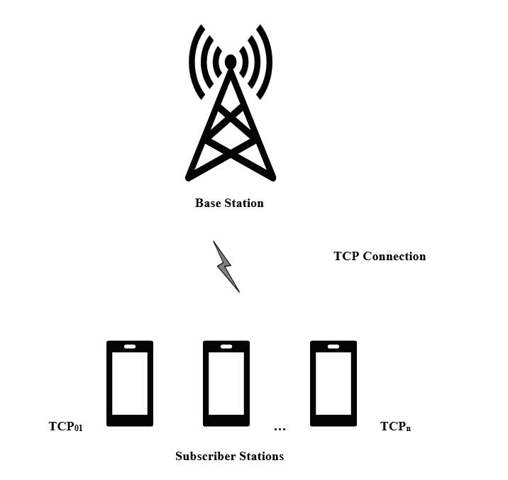
Theseservicesareusednotonlytomaximize thethroughputbutalsotominimizepacketdelays andreducesignalingoverheadsbypre‐allocatingand decentralizingcontrolledrelaystations.Thispaper alsomentioneddefaultradioresources,whichshow thatrelaystationsindependentlyassignresources withoutaskingthebasestationsothattraf ic,over‐head,andpacketdelayscanbereduced[21].
Thisworkinvestigatestheimprovedthroughput andminimumdelaysforenduserswithvariousappli‐cationslikevoice,video,andaudioservicesbyreduc‐ingthecostusingtheavailablespectralresourcesby usingrelaystations.Theproposedworkgivesacost‐effectivesolutionbyinstallingthethree‐relaystation withadaptivemodulationandcodingschemes,cell sectoring,anddirectionalantennasinIEEE802.16. Thisworkincreasedthethroughputwithalesser numberofrelaystationswithinthesamebasesta‐tionrangewithoutcompromisingthequalityofser‐vice[22].
ThisworkproposesrelaystationsinWiMAXnet‐workswithdifferentbandwidthallocationalgorithms toenhancethesignalpoweroverlongdistanceswith relaystations.Thispapershowsthattherelaystation extendsthecoveragewithhighthroughputandhigh bandwidthofchannels.Thispaperfocusesonper‐formanceanalysisofbandwidthallocationalgorithms withandwithoutrelaystations.Thisworkcompares thechannelbandwidthallocationalgorithmwithand withoutrelaystation,andperformanceenhancement isproposedandevaluated[5].
ThenetworkstructureshowninFigure1consists ofonebasestationandmanysubscriberstations.The basestation(BS)isconnectedtosubscriberstations (SS)throughindividualwirelessTCPconnections.The dataistransmittedfromthebasestationtothesub‐scriberstationsthroughawirelessmedium.Adown‐loadinglinkisestablishedfromthebasestationtothe subscriberstation,andthechannelisallocatedtosub‐scriberstationsusingRoundRobinandStrictPriority channelallocationtechniques;thebasestationtrans‐mitsdatatosubscriberstationsusingindividualTCP connectionswithallocatedchannelbandwidth,which isshowninFigure1forperformanceevaluation.
Variousnetworktoolsarealsoavailabletoperform thestudyofWiMAXnetworks,likeMATLAB,Netsim, Opnet,OMnet++,andmanymore.Onesuchsimulation toolisLightWiMAX[5].Toevaluatetheperformance ofWiMAXnetworkstheNetworkSimulator(NS‐2)is used.TheFrame_LWXtimer()functionisusedtoadd theMediumAccessControl(MAC)Layer.Oncethe packetsstarttransmitting,theMACsourceaddress andMACdestinationaddressarede ined.Portnum‐bersatthesourceanddestinationarealsode ined fordatatransmissionsinthecode.Ifnonodematch‐ingthedestinationaddressisfound,thepacketis dropped.DataisonlytransmittedfromBStoSS,and bandwidthallocationisdoneusingavariablede ined inthecode.
Inthesimulation,twovariablesareused:“1”for theroundrobinalgorithmand“2”fortheStrictPri‐orityalgorithm.Thecollectionofdownlink lowinto acorresponding lowqueueisstoredinthelinkpro‐gram.
Thebandwidthallocationalgorithmensures properbandwidthmanagementforthesmooth transmissionofnetworkstosubscriberstations.The StrictPriorityschedulingbasedoneitherpreemptive ornon‐preemptivebandwidthallocationalgorithm forwirelessnetwork.Priorityschedulinggenerally suffersfromtheproblemofstarvation;highpriority taskapplicationswillbeinreadyorwaitingcondition if,onthebasestation,theprocesslosescontrolin waitingconditions[23].Intheschedulingtechniques, thehigherpriorityprocessesareprocessed,whereas lowerpriorityprocessesareneglected.Innon‐prioritypreemptivescheduling,ittakesalongertime ascomparedtohigherpriorityprocessesonthebase station,whichcanleadtoastarvationcondition[24].
AnotheralgorithmistheRoundRobinalgorithm, whichisthepreemptiveschedulingalgorithm.Each processisgivenasetamountoftimetocomplete; thisisreferredtoasaquantum.Preemptionisneeded fortheexecutionofoneprocesswithinagiventime interval[25].Contextswitchingisusedtosavestates ofpreemptedprocesses[8].
Everybandwidthallocationalgorithmhasitsown channelallocationworkings[26].Thisworkusedthe framedurationwithRoundRobinandStrictPriority algorithms.Therearetwopathsthatcouldbechosen: onethatgoesdirectlytothebasestationandonethat goesthroughrelaystations.Inthispaper,twohop relaysthattransmitdatafromSStoBSonlyareused. VariousstepsareinvolvedwhenusingtheAODVrout‐ingprotocol,whichincludesthediscoveryofpaths, setupofpathselection,forwardpathselection,rout‐ingtablemanagementwithpathmaintenance,and localconnectivitymanagement.Themainadvantage ofusingtheAODVprotocolisthatitisscalableandcan beusedforalargenumberofnodes.Broadcastmini‐mizationisanotheradvantageofusingthisalgorithm. Anotheradvantageofusingthisroutingalgorithmis thatitreducesmemoryrequirementsandcanbeused innetworksforloop‐freeroutingmaintenance.
Forperformingthereal‐worldimplementationof thescenarios,NetworkSimulator2isasimulationtool usedtoperformvarioussimulations.Toexecutethe code,thistoolusedtheC++languageinconjunction withToolCommandLanguage[27].Thesimulation environmentsareusedtocarryouttheentiredeploy‐ment.Thistoolisanevent‐driventoolthatprovidesa dynamicenvironmentforcreatingscenariosthatare identicaltotherealparametersrequiredfornetwork creation.Simplecommandsareusedtoimplementthe toolforde iningnetworkcon igurations.
4.1.Algorithm1:RoundRobin–DownlinkBandwidth Allocation
1) Start
2) Createpointertoeach lowtype’squeuetoallo‐cation
3) GetsymbolnumberofDLandUL
4) Createalgorithmcalculationvariable
5) Resetallrelativevariables’valuein low’s attribute
6) SetPathselection
a) Findthepath(directlytoBSorpassingthough RelayStationRS)
b) SetBWA_Flow_TypeandBWA_Next_Hop
7) Selectpath
a) If(this lowhasrelaylink,usethe irstrelay linkanditsnexthop)
b) Elseuseaccesslink
8) Bandwidthallocation
a) Accesszone:RR+minQoSGurantee
b) Relayzone:onlyRR
i. Collect lowintocorresponding low queue
ii. Bs‐>SSandBS‐>RSshouldalsobe schedulingtogether,becausetheyusethe samebandwidth
9) Downlinkaccessbandwidthallocation
a) Satisfyeachdl low’sRmin
b) Satisfyeachdl lowbyRoundRobin
c) FinaldlBWAsetting
d) Logeachphase’sbandwidthallocationofeach downlink low
10) Downlinkrelaybandwidthallocation(RS‐>SS)
a) Satisfyeachdlrelay lowbyRR
b) FinaldlBWAsetting
c) Logeachphase’sbandwidthallocationtoeach downlinkrelay low
11) Uplinkaccessbandwidthallocation
a) Satisfyeachul lowRmin
b) Satisfyeachul lowbyRR
c) Logeachphase’sbandwidthallocationofeach downlink low
12) Uplinkrelaybandwidthallocation(RS‐>SS)
a) Satisfyeachulrelay lowbyRR
b) FinalULBWAsetting
c) Logeachphase’sbandwidthallocationofeach downlinkrelay low
d) Lwx_tests_msg(“RR’sULRelayBWA”)
e) Osttringstreamlog_send_plt
f) Log_send_pkt
g) Getpacket
h) Getlog
i) Lwx_test_msg(“dl”.Log_bwa.str());
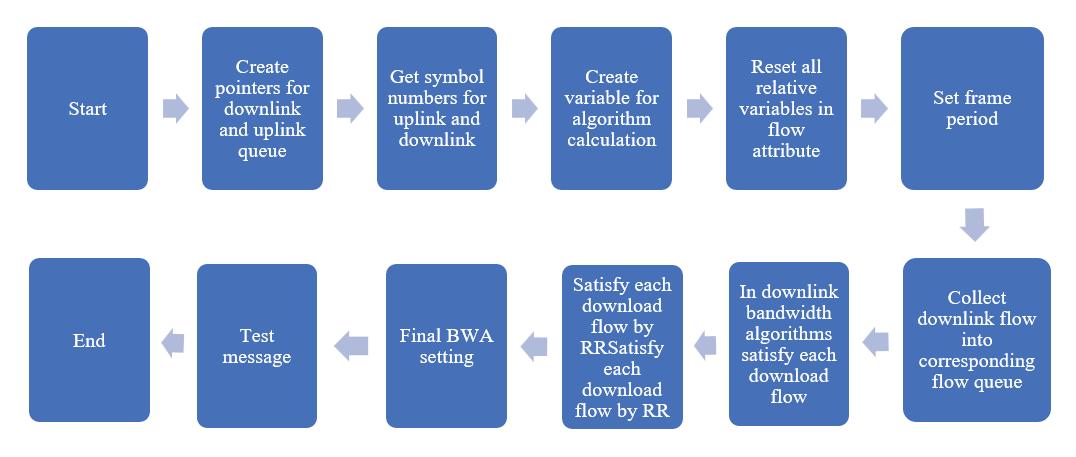
j) DecreaseBWA_Total
k) Pinthispacket
l) Senddownpacket
13) Timer lowchart:
a) Createpointertodownlinkanduplinkqueue toallocationbandwidthef iciently
b) Classify lowsofthenodeandcallthecorre‐spondingtransmissionfunctionswhosenode IDissourceintocorresponding lowqueue
14) EndTimer
15) End
4.2.Algorithm2:StrictPriority–DownlinkBandwidth Allocation
1) Start
2) Createpointertoeach lowtype’squeuetoallo‐cation
3) GetsymbolnumberofDLandUL
4) CreateStrictPriorityalgorithmcalculationvari‐able
5) Resetallrelativevariablesvaluein low’s attribute
6) SetPathselection
a) Findthepath(directlytoBSorpassingthough RelayStationRS)
b) SetBWA_Flow_TypeandBWA_Next_Hop
7) Selectpath
a) If(this lowhasrelaylink,usethe irstrelay linkanditsnexthop)
b) Elseuseaccesslink
8) Bandwidthallocation(StrictPriority)
a) Accesszone:RR+minQoSGurantee
b) Relayzone:onlyRR
i. Collect lowintocorresponding low queue
ii. Bs‐>SSandBS‐>RSshouldbealso schedulingtogether,becausetheyuse samebandwidth
9) Downlinkaccessbandwidthallocation
a) Satisfyeachdl low’sR‐min
b) Satisfyeachdl lowbyRoundRobin
c) FinaldlBWAsetting
d) Logeachphase’sbandwidthallocationofeach downlink low
10) Downlinkrelaybandwidthallocation(RS‐>SS)
a) Satisfyeachdlrelay lowbyRR
b) FinaldlBWAsetting
c) Logeachpahse’sbandwidthallocationtoeach downlinkrelay low
11) Uplinkaccessbandwidthallocation
a) Satisfyeacheachul‐ lowR‐min
b) Satisfyeachul‐ lowbyRR
c) Logeachpahse’sbandwidthallocationofeach downlink low
12) Uplinkrelaybandwidthallocation(RS‐>SS)
a) Satisfyeachulrelay lowbyRR
b) FinalULBWAsetting
c) Logeachphase’sbandwidthallocationofeach downlinkrelay low
d) Lwx_tests_msg(“RR’sULRelayBWA”)
e) Osttringstreamlog_send_plt
f) Log_send_pkt
g) Getpacket
h) Getlog
i) Lwx_test_msg(“dl”.Log_bwa.str());
j) DecreaseBWA_Total
k) Pinthispacket
l) Senddownpacket
13) Timer lowchart:
a) CreatepointertodownlinkanduplinkStrict Priorityqueueforallocationofbandwidth
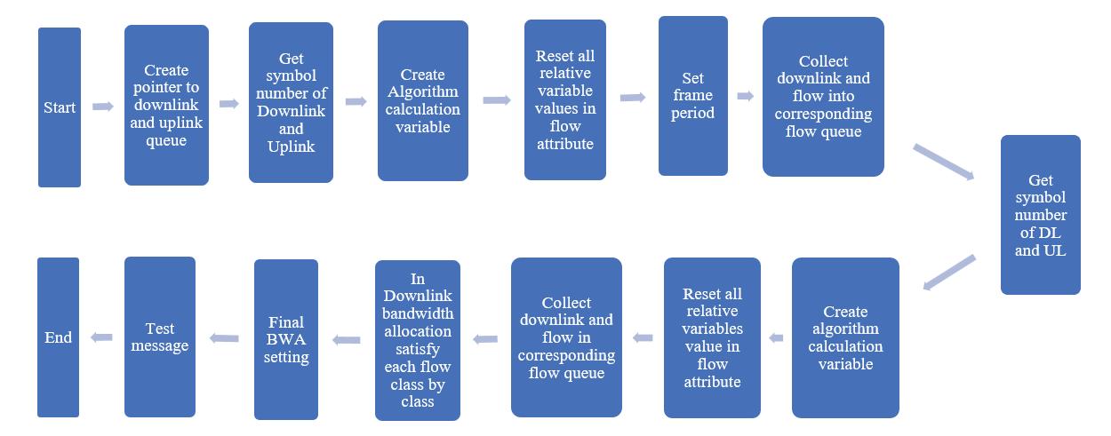
b) Classify lowsofthenodeandcallthecorre‐spondingtransmissionfunctionswhosenode idissourceintocorresponding lowqueue
14) EndTimer
15) End
5.1.SimulationParameters
Table1showsthevarioussimulationparameters usedinthiswork.Oneoftheparametersusedinthis workisaroutingtablebasedonad‐hoctechniques. On‐demandroutingprotocolsusedinwirelessnet‐worksareloop‐freeprotocols.Thisprotocolisaself‐startingprotocolusedinthesubscriberstationenvi‐ronment.Thisisalsousedtoimplementvariousother parameterslikemobilityofnodes,failurelinkman‐agementprotocols,andlossofpacketidenti ication. Hence,toidentifyalltheseworksinwirelessworks, theAODVprotocolplaysanimportantrole.
Ad‐hocon‐demandroutingprotocolismaintained byaroutingtable,whichkeepsthedetailsaboutthe nearbyrouters[28].Theroutingtablemaintainedby AODVconsistsofthreetypesofinformation,including thenexthopcount,sequencenumbers,andthetotal hopcount,whichisneededtotransferthedataamong thenodes.Next,hopcountisusedtoidentifythe distanceofcurrentnodestotheintendednodes.
Thesecondparameterusedistransmissionpro‐tocol,whichmaybeeitherconnection‐orientedor connection‐less.Inthiswork,atransmissioncontrol protocolisused[29].Twoalgorithms,RoundRobin algorithmandStrictPriority,areusedinthiswork. Also,asustainabletimeof300secondsisusedforsim‐ulationstohaveaccurateresults.Subscriberstations, referredtoasnodesinthispaper,areassignedinitially withtennumbersandincreaseupto100nodeswith adifferenceof10nodeseachtime.Inthiswork,the frameperiodis5ms,2.5ms,1.25,and0.625millisec‐ondsaretaken,andtherestoftheparametersarevar‐iedtoanalyzetheperformanceofWiMAXnetworks.
Parameters Values
RoutingProtocols AdHocOnDemandRouting Protocol
TransportProtocol TransmissionControl Protocol(TCP)
BandwidthAllocation Algorithm RoundRobin(RR)and StrictPriority(SP)
SimulationDuration 300Seconds
NumberofWireless
Nodes 10,20,30……upto100
FrameDuration 0.005,0.0025,0.00125, 0.000625Millisecond
FrameSymbol 48
Thefollowingparametersareconsideredforana‐lyzinglightWiMAXnetworks,whichareshownin Table1.
5.2.PerformanceEvaluation
Theperformanceevaluationisdoneonthebasisof thefollowingmatrices:
1) Throughput:Therawdatasentbythesender machineduringaspeci iedduration.
Throughput = NumberofPacketsSent ∗8
SimulationDuration
∗10−6 Mbps (1)
Wherethe,
Numberofpacketssent: Totalpacketssentby sendermachineofsize1024Byteeach.
SimulationDuration: Thedurationofdatatrans‐ferinseconds.
2) Goodput:Thepacketssuccessfullyreceivedand acknowledgedbyreceivermachine.
Goodput = NumberofPacketsReceived ∗8
SimulationDuration
∗10−6 Mbps (2)
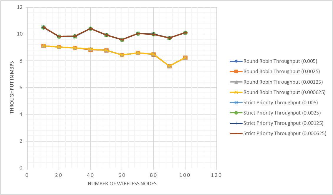
Wherethe, Numberofpacketsreceived: Totalpackets receivedbyreceivermachineofsize1024Byte each.
SimulationDuration: Thedurationofdatatrans‐ferinseconds.
3) PacketDrop:Totalpacketsdroppedduringthe communicationduration.
DropRate = NumberofPacketsDropped ∗8 SimulationDuration
∗10−6 Mbps (3)
Wherethe, Numberofpacketsdropped: Totalpackets droppedofsize1024Byteeach.
SimulationDuration: Thedurationofdatatrans‐ferinseconds.
ItisevidentfromFigure 4 thatathroughputof 9.12Mbpsfor10nodesisobservedintheRound Robinalgorithm,whichismuchbetterthanStrictPri‐ority.Throughputalsodecreaseswiththeincreasing numberofnodes.Acomparativeanalysisrevealsthat RoundRobinhasan88.4%higherStrictPriorityfor 20nodes.Thethroughputfor50subscriberstations is8.79Mbpsand9.92MbpsfortheRRandSPalgo‐rithms,respectively.Similarly,forRoundRobinand StrictPriority,itisobtainedat8.59Mbpsand10.04 Mbpsfor70nodes,respectively.Continuousdegrada‐tionisobservedasthenumberofnodesincreasesin thetwoalgorithms.Thesameresultsarecontinuously observedasthenumberofnodesincreases.Strict Priorityisfoundtobe11.39%moreef icientthan RoundRobinfor50nodesand18.33%betterfor100 nodes.Asthenumberofnodesincreases,throughput decreasesinbothRoundRobinandStrictPriority, duetothefullutilizationofthechannelandmaxi‐mumbandwidthutilizations.Whensubscriberstation
increasessingleorthogonalfrequencydivisionmul‐tiplexingsymbolusesmultiplebitswhichdegrades thethroughputofthechannel.Asthenumberofsub‐scriberstationsincreases,multiplebitsarecarriedin asingleOFDMsymbol.Ashorterframeperioduses thechannel’smaximumbandwidth,andthroughputis higherforfewernodes.Theeffectduetodelayspread isminimizedwhenalongerdatasymbolisused,and whendelayspreadissmall,itbecomesaninsigni icant fractionofthesymbollength.Onincreasingsubscriber stations,fullutilizationofthebasestationisused, whichusesawiderchannel.
Figure5showsthatasmallernumberofnodesper connectioncanalsoleadtohighergoodput,thatis, 9.51MbpsobtainedusingtheRoundRobinalgorithm for10subscriberstations.Theobservedgoodputis 9.03Mbpsfor20subscribers.Italsoobtained8.39 Mbpsand6.75Mbpsgoodputfor60subscribersta‐tionsinroundrobinandStrictPriority.Theobtained goodputfor80subscriberstationsis8.45Mbpsand 8.3MbpsforroundrobinandStrictPriority,respec‐tively.Theobtainedgoodputfor100nodesis8.19 Mbpsand10.15MbpsforroundrobinandStrictPri‐ority,respectively.Whenacomparativeanalysisis done,itisobservedthatroundrobinforrelayper‐forms89.1%betterforStrictPriorityfor10nodes, 87.4%betterfor30nodes,81.8%betterfor60nodes, 82.4%betterfor80nodes,and79.7%betterfor100 nodes.ThisdemonstratesthatStrictPrioritydoesnot performbetterintermsofthroughputforstations withfewersubscribers.Asthenumberofpacketssent persecondwentup,sodidtheamountofdatathat couldbesentthroughthechannel.Themostdata issentthroughchannelswithfewersubscribers[7]. Whenacomparativeanalysisisdone,RoundRobin performsmuchbetterthanStrictPriority.Whenthe numberofnodesincreases,thegoodputinbothcases decreasesduetothedroppingofpacketsoccurring (busychannel).Whenthenumberofnodesincreases, performancesuffersasthechannelisfullyutilized, resultinginanincreaseddroprate.

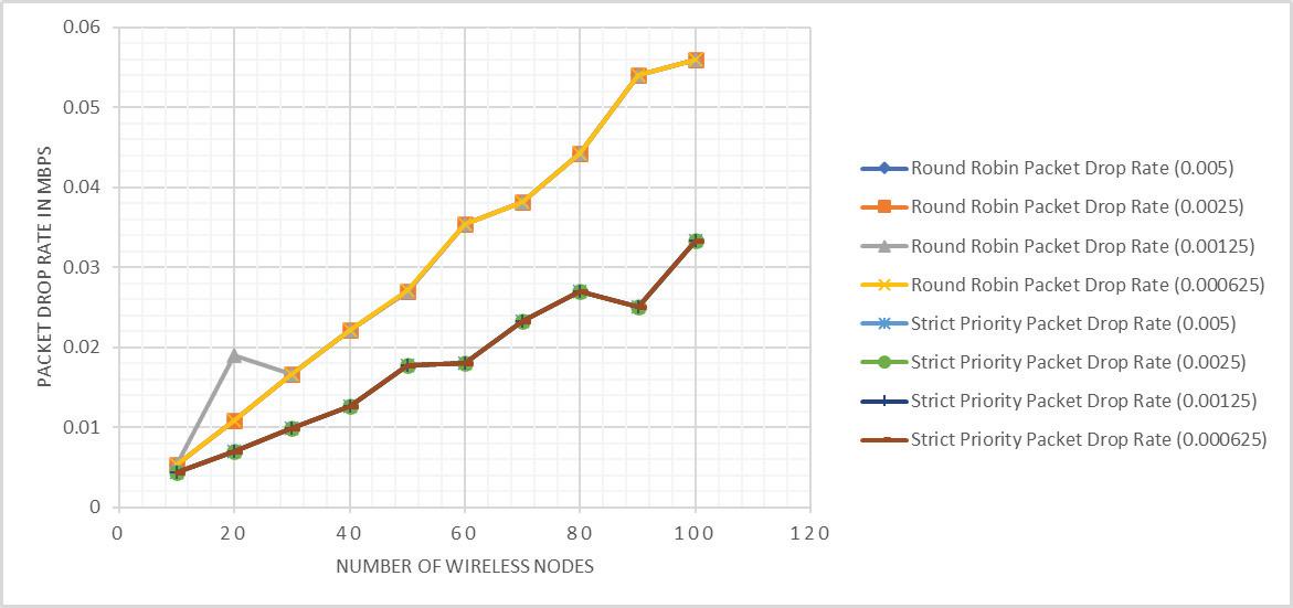
Figure4showsthatthedroppedpacketsinStrict Priorityaremuchhigherascomparedwithround robin.Therateofpacketdropsincreasedasthenum‐berofsubscriberstationsincreasedbecausesignals wereinitiallytransmittedwithmaximumpowerfrom basestations,reducingthelikelihoodofsignallosses. Similarly,astraf icloadsincrease,itbecomesdif icult tomaintainasmanysubscriberstations,andtheyare droppedafteralongperiodofwaiting[24].Figure4 showsthatthedropratealsoincreasedduetothe unavailabilityofmodulationoverlongdistances.Ini‐tially,packetdropratesof0.005,0.016,0.027,0.032, and0.056Mbpsareobtainedfor10,30,50,70, and100nodes,respectively,forStrictPriorityand RoundRobin,whichisshowninTable2.Asthenodes increase,thepacketdropratealsoincreasesby0.002, 0.007,0.010,0.014,0.019,and0.024Mbpsfor10,30, 50,70,and100nodes,respectively,forStrictPriority. Thevariationindataratedependsonwhetherthe receiverisinlineofsightornot[26].Incasesofnon‐line‐of‐sight(NLOS),thedataratesdropsigni icantly duetotheadaptivemodulation[30].Whencompar‐ingallthreealgorithms,thedroprateishigherin StrictPrioritywhenthesubscriberstationsincrease. Itisobservedthat37.2%,42.15%,41.7%,49.9%,and 37.3%arehigherthanStrictPriorityfor,respectively, 10,30,50,70,and100nodes.
Figure7showsthatroundrobinandStrictPriority algorithmswithanumberofnodesequalto10in eachcasearecomparedwithpreviouslyproposedEDF andDRRFonthebasisofframedurationandchannel bandwidthallocation.ItisobservedthatStrictPrior‐ityandRoundRobinperformmuchbetterinterms ofthroughputascomparedtoEDF,whichisshown inTable 3 whentaking10nodesineachcase.Itis observedfromtheanalysisthatRoundRobinper‐forms83.8847%betterwhileStrictPriorityperforms 86.0220%betterinthecaseofamaximumof10 subscriberstations.
Sincepreviousalgorithmshavenotmentionedthe throughputformorethan10nodes,hencethecom‐parisonsfor20,40,60,and80nodesarenotshownin thiswork.So,forthesenodes,comparisonsbetween thetwoalgorithmsareavailableonly.So,fortherest ofthenodes,thecomparisonsofStrictPriorityand RoundRobinaredoneinthiswork.Itisobserved fromtheanalysisthat,fornodes,throughputis7.84% higherthanRoundRobininthecaseof20nodes. Itisobservedthat14.61%and15.01%arehigher thanRoundRobinfor40and80nodes.Theanalysis showsthathigherthroughputisobservedmorein StrictPrioritythantheRoundRobinalgorithmineach case.Higherthroughputisobservedduetosuccessful sendingofpacketsfrombasestationtosubscriber station.
Table2. ComparisonofbandwidthallocationalgorithminWiMAXnetworkswiththroughput
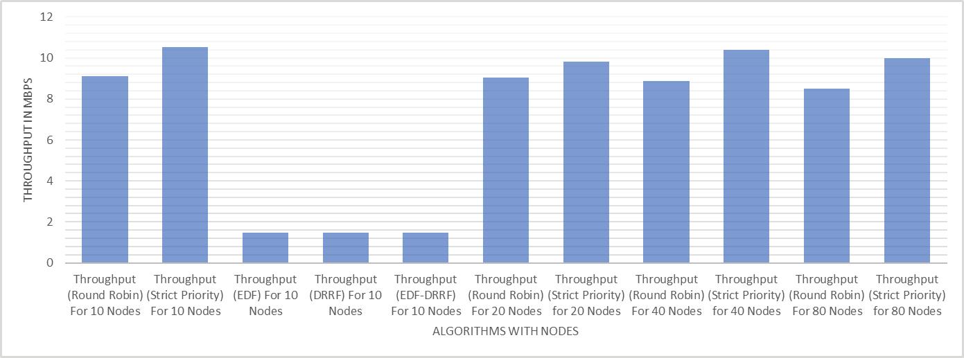
Table3. ComparisonofbandwidthallocationalgorithminWiMAXnetworkswithgoodput
Throughputisgenerallyconsideredasaggregate sinceitisdependentonmanyfactorslikeinterfer‐enceincludingradio,physical,andelectricalsignals. Anotherfactorthatimpactsthroughputisdistance betweenthebasestationandsubscriberstations.Var‐iousotherobstacleslikegeographicalinfrastructure ofEarthisalsoaparameterthroughwhichthroughput receiveimpactsin2.4GHzbandinwirelesscommuni‐cationsystems.
Figure8showsthatroundrobinandStrictPrior‐ityalgorithmswithnumbersofnodesequalto10in eachcasearecomparedwithpreviouslyproposedEDF andDRRFonthebasisofframedurationandchannel bandwidthallocation.ItisobservedthatStrictPriority andRoundRobinperformmuchbetterintermsof goodputascomparedtoEDF.Basedontheanalysis, RoundRobinworksbetterforupto10subscribers
by83.8752%,whileStrictPriorityworksbetterby 86.0163%.
Sincepreviousalgorithmshavenotmentionedthe goodputformorethan10nodes,hencethecompar‐isonsfor20,40,60,and80nodesarenotshownin thiswork.So,forthesenodes,goodputcomparisons betweentheproposedtwoalgorithmsareavailable only.So,fortherestofthenodes,thecomparisons ofStrictPriorityandRoundRobinaredoneinthis work.Itisobservedfromtheanalysisthatfornodes, goodputisobservedtobe7.95%higherthanRound Robininthecaseof20nodes,whileitisobservedtobe 17.16%and15.25%higherthanRoundRobinfor40 and80nodes.Theanalysisshowsthathighergoodput isobservedinStrictPrioritythanRoundRobinalgo‐rithmineachcase.Highergoodputisobserveddueto thesuccessfulsendingofpacketsfromthebasestation tothesubscriberstation.


Goodputisalsodependentonmanyfactorslike interference,includingradio,physical,andelectrical signals.Anotherfactorthatimpactsgoodputisthe distancebetweenthebasestationandsubscriber stations.Variousotherobstacleslikethegeographi‐calinfrastructureoftheeartharealsoaparameter throughwhichgoodputreceiveimpactsinthe2.4GHz bandinwirelesscommunicationsystems.
Figure9showsapercentwisecomparativeanaly‐sisintermsofthroughputandgoodputfor10nodes ofEDFwithStrictPriorityandRoundRobin.Italso showsacomparisonofStrictPriorityandRound Robinalgorithmsfor20,40,and80nodessincepre‐viousworkforagreaternumberofnodesisnotmen‐tionedinthereferencedpapers.Overall,itisobserved thatStrictPriorityperformsmuchbetteramongall threealgorithmsintermsofthroughputandgoodput.
6.Conclusion
Theworkisusedtoenhancetheperformanceof WiMAXnetworkswithvariousframeperiods.Also, thisworkisdonetoenhancetheperformancebyvary‐ingframeperiodsinthealgorithms,anditisobserved fromtheanalysisthatvaryingtheframeperiodinthe algorithmreallyenhancestheperformanceofWiMAX networks.Theenhancementisdonebychangingthe existingalgorithmandaddingthenewframeperiods. Thisanalysisalsoshowsthatduringthebandwidth allocation,iftheframeperiodisvaried,thensomehow aStrictPriorityalgorithmgivesbetterresultsinthe formofthroughput,goodput,andpacketdroprate.
TheStrictPrioritybandwidthallocationalgo‐rithmsgivebetterresultsascomparedtoroundrobin algorithmsforallframeperiods.Whentheframe periodis0.005milliseconds,roundrobinandStrict PriorityperformmuchbetterthantheEarliestDead‐lineFirstAlgorithm(EDFA)inWiMAXnetworks.It isobservedfromtheanalysisthatRoundRobinper‐forms83.8%,whileStrictPrioritygives86.2%bet‐terthroughputthanthe“earliestdeadline irst”algo‐rithmfor10subscriberstations.Similarly,itisalso observedthatGoodputperforms83.60%andStrict Priority86.01%betterfor10subscriberstationsthan thetraditionalRoundRobinalgorithmand90%better thanStrictPriorityinformsofthroughput.Asmaller frameperiodgivesbetterresultsforef icientdata transmission.Thestudyalsofoundthatwhenthe numberofnodesisreduced,thethroughputincreases [24,31–33].
Thewholeworkcanbecarriedoutwithvarious qualityofserviceparameterswhichmayincludebest effort,realtimepolingservice,non‐realtimepoling service,unsolicitedgrantserviceandextendedreal timepolingservices.Differentchannelallocationscan alsobedoneforanalysis.Thiswholeanalysiscould alsobedonewith5Gnetworks.
MubeenAhmedKhan –DepartmentofComputerSci‐enceandEngineering,SangamUniversity,Bhilwara, Rajasthan,India,e‐mail:makkhan0786@gmail.com.
AwanitKumar –DepartmentofComputer ScienceandEngineering,SangamUniver‐sity,Bhilwara,Rajasthan,India,e‐mail: awanit.kumar@sangamuniversity.ac.in.
KailashChandraBandhu∗ –DepartmentofCom‐puterScienceandEngineering,Medi‐CapsUniversity, Indore,MadhyaPradesh,India,e‐mail:kailashchan‐dra.bandhu@gmail.com.
∗Correspondingauthor
References
[1] “IEEEStandardforLocalandMetropolitanArea NetworksPart16:AirInterfaceforFixedBroad‐bandWirelessAccessSystems,” IEEEStd802.162004(RevisionofIEEEStd802.16-2001),pp.1–857,2004,doi:10.1109/IEEESTD.2004.226664.
[2] “IEEEStandardforLocalandMetropolitanArea Networks–Part16:AirInterfaceforFixed andMobileBroadbandWirelessAccessSys‐tems–AmendmentforPhysicalandMedium AccessControlLayersforCombinedFixedand MobileOperationinLicensedBands,” IEEEStd 802.16e-2005andIEEEStd802.16-2004/Cor12005(AmendmentandCorrigendumtoIEEE Std802.16-2004),pp.1–822,Feb.2006,doi: 10.1109/IEEESTD.2006.99107.
[3] K.M.Ahmed,K.Sarita,andT.Vibha.“Perfor‐manceAnalysisofWiMAXNetworkswithRelay Station,” InternationalJournalonRecentTrends inEngineering&Technology,vol.8,no.1,p.30, 2013.
[4] C.Eklund,R.B.Marks,K.L.Stanwood,and S.Wang.“IEEEstandard802.16:atechnical overviewoftheWirelessMAN/supTM/airinter‐faceforbroadbandwirelessaccess,” IEEECommunicationsMagazine,vol.40,no.6,pp.98–107, Jun.2002,doi:10.1109/MCOM.2002.1007415.
[5] M.A.Khan,A.Kumar,andK.C.Bandhu.“World‐wideInteroperabilityforMicrowaveAccessnet‐workoptimizationwithandwithoutrelaysta‐tionfornextgenerationinternetaccess,” InternationalJournalofCommunicationSystems,vol.35, no.17,p.e5318,2022,doi:10.1002/dac.5318.
[6] E.L.Hahne.“RoundRobinschedulingforfair lowcontrolindatacommunicationnetworks,” Thesis,MassachusettsInstituteofTechnology, 1986.accAvailable: https://dspace.mit.edu/h andle/1721.1/14932.
[7] M.Katevenis,S.Sidiropoulos,andC.Courcou‐betis.“WeightedRoundRobincellmultiplexing inageneral‐purposeATMswitchchip,” IEEE JournalonSelectedAreasinCommunications,
vol.9,no.8,pp.1265–1279,Oct.1991,doi: 10.1109/49.105173.
[8] A.Silberschatz,P.B.Galvin,andG.Gagne, OperatingSystemConcepts.Wiley,2005.
[9] P.Goyal,H.M.Vin,andH.Chen.“Start‐timefair queueing:aschedulingalgorithmforintegrated servicespacketswitchingnetworks,” SIGCOMM Comput.Commun.Rev.,vol.26,no.4,pp.157–168,Aug.1996,doi:10.1145/248157.248171.
[10] S.Ahmadi.“Anoverviewofnext‐generation mobileWiMAXtechnology,” IEEECommunicationsMagazine,vol.47,no.6,pp.84–98,Jun. 2009,doi:10.1109/MCOM.2009.5116805.
[11] C.So‐In,R.Jain,andA.‐K.Tamimi.“ADe icit RoundRobinwithFragmentationschedulerfor IEEE802.16eMobileWiMAX,”in 2009IEEE SarnoffSymposium,Mar.2009,pp.1–7.doi: 10.1109/SARNOF.2009.4850308.
[12] J.Rakesh,W.V.A.,andU.Dalal.“ASurveyof MobileWiMAXIEEE802.16mStandard.”arXiv, May06,2010.doi:10.48550/arXiv.1005.0976.
[13] R.NandhiniandN.Devarajan.“Comparisonfor WiMAXSchedulingAlgorithmsandProposal QualityofServiceImprovementinWiMAXNet‐works,” AJAS,vol.11,no.1,pp.8–16,Nov.2013, doi:10.3844/ajassp.2014.8.16.
[14] H.K.RathandA.Karandikar.“Performanceanal‐ysisofTCPandUDP‐basedapplicationsinaIEEE 802.16deployednetwork,”in 2011The14th InternationalSymposiumonWirelessPersonal MultimediaCommunications(WPMC),Oct.2011, pp.1–5.Available:https://ieeexplore.ieee.org/ document/6081520
[15] N.Mazhar,M.Zeeshan,andA.Naveed.“Per‐formanceImpactofRelaySelectioninWiMAX IEEE802.16jMulti‐hopRelayNetworks,” InternationalJournalofAdvancedComputerScience andApplications(IJACSA),vol.10,no.9,Art.no. 9,36/302019,doi:10.14569/IJACSA.2019.010 0950.
[16] D.Rathore,A.Shukla,andG.Jaiswal.“Perfor‐manceEvaluationofWeightedRoundRobin SchedulingforWiMAXNetworksUsingQualnet Simulator6.1,” IOSRJournalofElectronicsand CommunicationEngineering,vol.9,pp.77–81, Jan.2014,doi:10.9790/2834‐09257781.
[17] Z.Tao,A.Li,K.H.Teo,andJ.Zhang.“Frame StructureDesignforIEEE802.16jMobileMul‐tihopRelay(MMR)Networks,”in IEEEGLOBECOM2007–IEEEGlobalTelecommunications Conference,Nov.2007,pp.4301–4306.doi: 10.1109/GLOCOM.2007.818.
[18] R.Mahmood,M.Tariq,andM.Khiyal.“ANovel ParameterizedQoSbasedUplinkandDown‐linkSchedulerforBandwidth/DataManagement overIEEE802.16dNetwork,” InternationalJournalofRecentTrendsinEngineering,vol.2,pp.42–46,Nov.2009.
[19] P.Kolomitro,M.T.Abd‐Elhamid,andH.Has‐sanein.“Aperformancecomparisonofframe structuresinWiMaxrelaynetworks,”in IEEE LocalComputerNetworkConference,Oct.2010, pp.769–776.doi:10.1109/LCN.2010.5735810.
[20] A.F.BayanandT.‐C.Wan.“AscalableQoS schedulingarchitectureforWiMAXmulti‐hop relaynetworks,”in 20102ndInternational ConferenceonEducationTechnologyand Computer,Jun.2010,pp.V5‐326‐V5‐331.doi: 10.1109/ICETC.2010.5530061.
[21] P.MachandR.Bestak.“Radioresourcesallo‐cationfordecentrallycontrolledrelaystations,” WirelessNetw,vol.17,no.1,pp.133–148,Jan. 2011,doi:10.1007/s11276‐010‐0269‐8.
[22] N.Ahmed,M.AliShah,andS.Zhang.“Ef icient DeploymentofRelayStationsinIEEE802.16m forCostEffectivePerformance,” ProcediaComputerScience,vol.10,pp.992–997,Jan.2012,doi: 10.1016/j.procs.2012.06.135.
[23] KhanMubeenAhmedandBandhuKailashChan‐dra.“AnalysisofWiMAXNetworkswithBand‐widthAllocationAlgorithms(RoundRobinand StrictPriority),” InternationalJournalofRecent TechnologyandEngineering,vol.8,no.4,pp.19–22,Jun.2019.
[24] A.Sayenko,O.Alanen,andT.Hämäläinen. “SchedulingsolutionfortheIEEE802.16base station,” ComputerNetworks,vol.52,no.1,pp. 96–115,Jan.2008,doi:10.1016/j.comnet.200 7.09.021.
[25] D.VandanaandM.Sharma.“RoundRobinCPU SchedulingwithDynamicQuantumusingVague Sets,” InternationalJournalofAdvancedScience andTechnology,vol.29,pp.9940–9950,Jul. 2020.
[26] Y.‐C.LaiandY.‐H.Chen.“DesigningandImple‐mentinganIEEE802.16NetworkSimulatorfor PerformanceEvaluationofBandwidthAlloca‐tionAlgorithms,”in 200911thIEEEInternational ConferenceonHighPerformanceComputingand Communications,Jun.2009,pp.432–437.doi: 10.1109/HPCC.2009.40.
[27] K.C.BandhuandR.G.Vishwakarma.“Perfor‐manceevaluationofTCPVegasinWiMAXnet‐workasymmetry,” IJWMC,vol.10,no.2,p.97, 2016,doi:10.1504/IJWMC.2016.076165.
[28] K.C.Bandhu.“PerformanceComparisonof TransmissionControlProtocolVariantsin WiMAXNetworkwithBandwidthAsymmetry,” in InternationalConferenceonAdvanced ComputingNetworkingandInformatics,R. Kamal,M.Henshaw,andP.S.Nair,Eds.,in AdvancesinIntelligentSystemsandComputing. Singapore:Springer,2019,pp.247–261.doi: 10.1007/978‐981‐13‐2673‐8_27.
[29] S.R.Das,C.E.Perkins,andE.M.Belding‐Royer.“AdhocOn‐DemandDistanceVector (AODV)Routing,”InternetEngineeringTask Force,RequestforCommentsRFC3561,Jul. 2003.doi:10.17487/RFC3561.
[30] S.A.AhsonandM.Ilyas. WiMAX:Technologies, PerformanceAnalysis,andQoS.CRCPress,2018.
[31] A.Kumar. MobileBroadcastingwithWiMAX: Principles,Technology,andApplications.Taylor& Francis,2014.
[32] K.C.BandhuandR.G.Vishwakarma.“TheImpact ofCyclicPre ix,ModulationCodingScheme, FrameDuration,TwoWayTransferandPropaga‐tionModelwithNetworkAsymmetryinWimax NetworkusingTCPNewReno,” International JournalofEngineeringResearch&Technology, vol.3,no.3,Mar.2014,doi:10.17577/IJERTV3 IS030495.
[33] KailashChandraBandhuandRajeevG.Vish‐wakarma.“PerformanceEvaluationofTCPSack1 inWiMAXNetworkAsymmetry,” International JournalofResearchinEngineeringandTechnology,vol.3,no.2,pp.112–120,Dec.2014.
Abstract:
DOI:10.14313/JAMRIS/4‐2023/32
Submitted:25th September2022;accepted:27th February2023
AliMedjebouri
Oneoftheexamplesoftheseclassicaltoolsisthe PIDcontrollerwidelyusedinindustrialapplications [5–7].
Inthechemicalandpetrochemicalindustry,theContinu‐ousStirredTankReactors(CSTR)are,withoutdoubt,one ofthemostpopularprocesses.Fromacontrolpointof view,themathematicalmodeldescribingthetemporal evolutionoftheCSTRhasastronglynonlinearcross‐coupledcharacter.Moreover,modelingerrorssuchas externaldisturbances,neglecteddynamics,andparame‐tervariationsoruncertaintiesmakeitscontroltaskavery difficultchallenge.Eventhoughthisproblemhasbeen thesubjectofawidenumberofcontrolstrategies,this articleattemptstoproposeaviable,robust,nonlinear decouplingcontrolscheme.Theideabehindtheproposed approachliesinthedesignoftwonestedcontrolloops. Theinnerloopisresponsibleforthecompensationofthe nominalmodelnonlinearcross‐coupledtermsviastatic nonlinearfeedback;whereastheouterloop,designed aroundanExtendedStateObserver(ESO)ofwhichthe additionalstategatherstheglobaleffectofmodeling errors,ischargedtoinstantaneouslyestimate,andthen tocompensatetheESOextendedstate.Thisway,the CSTRcomplexdynamicsarereducedtoaseriesofdecou‐pledlinearsubsystemseasilycontrollableusingasimple Proportional‐Integral(PI)linearcontroltoensurethe robustpursuitofreferencesignalsrespectingthedesired performance.Thepresentedcontrolvalidationwasper‐formednumericallybyanobjectivecomparisontoaclas‐sicalPIDcontroller.Theobtainedresultsclearlyshowthe viabilityandtheeffectivenessoftheproposedcontrol strategyfordealingwithsuchnonlinear,stronglycross‐coupledplantssubjecttoawiderangeofdisturbances despitetheprecisionoftheirdescribedmathematical model.
Keywords: CSTR,Robustcontrol,FeedbackLinearization, ESO
TheCSTRisoneofthemostusedpiecesofequip‐mentinprocessengineering.Itsmainroleistocon‐vertreactantsinto inishedorsemi‐ inishedprod‐ucts;therefore,itplaysaprimaryroleinmanychem‐icalprocesses[1–4].CSTRsaregenerallycontrolled aroundacertainequilibriumpoint,whereitisapprox‐imatedbyalocallyvalidlinearmodel.Thisapproach hastheadvantageofsimplifyingthesynthesisofthe controllersbecauseitallowstheuseofallclassical linearcontroltheorytools.
Unrivaledsinceitappearedin1922[8],thePID controllerhasdominatedtheindustrialsceneallover thepastcentury,allowingthepropulsionofthetech‐nologicalrevolutiontowardnewhorizonseveninits simpleform.ThehugesuccessofPIDcontrolinthe practitioner’ssocietyliesessentiallyinthesimplicity ofthedesignandimplantationtasks.Nevertheless, pressedbymodernindustrydemandsincreasingly moreandmoreexigentintermsofef iciency,control theorywasalwaysconstrainedtodevelopnewcontrol mechanismssatisfyingthenewlyimposedrequire‐ments[9, 10].Insearchofnewadvancedcontrol schemes,theorieshaveevolvedinseveraldirections, givingaveryrichbibliographyover80years.
FortheCSTRcontrolexample,variouscontrol strategies,suchastheexactfeedbacklinearization control[11, 12],thenonlinearbacksteppingcon‐trol[2],themodelpredictivecontrol[4,13–19],dif‐ferentoptimalcontrolstrategies[20–23],theadap‐tivecontrolapproaches[24–27],andtheslidingmode controltheory[1,28–32]havebeenproposedamong others.Wecanalso indseveralarticlesbasedon successfulcombinationsbetweenadvancednonlinear controltheoriesandsoftcomputingtoolssuchasarti‐icialneuralnetworks(ANN)[33,34],fuzzyinference systems(FIS)[3,35],andmanybio‐inspiredoptimiza‐tionalgorithmssuchasthegeneticalgorithm(GA)[7, 36],etc.Thesecombinationshavebeenaddressed,in general,toovercomesomespeci icdif icultiesrelated tocertainsyntheticdif icultiesinducedbythemathe‐maticalrigoroftheoriginalapproaches,ortoalleviate somedisadvantagespresentedbythepreviouslycited controls.
However,inthemidstofthistheoreticalrevolution inthecontrol ield,theindustryseemsuninterested inmostoftheproposedmoderncontrolapproaches bypresentingahighin lexibilityforPIDcontrol,even knowingitsshortcomingswell,despitetheimprove‐mentsintroducedtoitduringthepastdecades.This fact,probably,liesintheirpragmaticwayofre lec‐tion,aimingmostofthetimetoachieveasuf iciently acceptablecompromisebetweenthecontrollerdesign simplicityandtherequiredperformance.Ontheother hand,itseemsthattheyaremissingoutontheoppor‐tunitiesofferedbythegreatdigitalrevolutionasthey
cannotfullytakepro itfromthemoderndigitalpro‐cessor’scapacities[9,10].
Bornasanecessitytoestablishnewbridges betweenmodernindustrydemandsandmoderncon‐troladvances,theActiveDisturbanceRejectionCon‐trol(ADRC)wasintroducedforthe irsttimeinthe originaltextin[37]andafewyearslaterfortheAnglo‐phonesocietyin[38].Itwasthefruitofmuchwork fedbyadeepcomprehensionofbothpractitioners’ andacademicresearchers’wayofre lectingwhenit comestoaddressingcontrolsystemsproblems,the constraintsandthechallengesfacingthem,andthe opportunitiesofferedbytheaccelerateddevelopment ofdigitaltechnology.
EventheADRCoriginalframeworkiscomposed from ivemaincomponents;theExtendedState Observer(ESO)representsthecontroller’scorner‐stone.TheADRCideaisbasedontherealtimeestima‐tionandtheactivecompensationofthetotalin luence ofthemodelnonlinearitiescombinedwiththediffer‐entdisturbancetypes,suchasexternaldisturbances, modelingerrors,parametersvariationsoruncertain‐ties,etc.Theglobaleffectofthemodelnonlinearities anddisturbancesisconsideredastheobserver’saug‐mentedstate.
Owingtoitsgreatpotentialfordealingwithawide rangeofdisturbancestructures,ESObasedrobust control,includingtheADRCoriginalversion,haspre‐sentedanunmistakableviabilitytoaddressalargeset ofpracticalcontrolapplicationsbeforeevenhavinga rigorousproofoftheoreticalfundamentalquestions suchastheESOconvergenceortheclosedloopstabil‐itywhichcameseveralyearslater[39–43].Moreover, ithasshownahigh lexibilitytohandlemanymore applicationsthanPIDcontrol,suchastimedelayed systemscontrol,multivariabledecoupledcontrol,cas‐cadecontrol,andparallelsystemcontrol[10].Also, ESObasedcontrolhasknownsomemajoradvances inthecontextofitsgeneralizationtomorecomplex problemsinthelastfewpastyears,suchasstochastic systemscontrol[44]anddistributedparametercon‐trolsystems[43].
Motivatedbythehugepotential,thesimplicityof thedesignprocedure,andthewideimmergenceof ESObasedrobustcontrolparadigminsimulationand engineeringapplications,readerscanrefertothelit‐erature[45–49].Inthispaper,weattempttoillus‐tratehowtousetheESOforimprovingthenonlinear multivariabledecoupledcontrolrobustnessinasim‐pleandclearmanner.Theproposedmethod’smain idealiesintheuseofconventionalexactfeedback linearizationcontrol,widelyusedfordealingwith multivariableaf inenonlinearplantsinassociation withanextendedstateobserverchargedtoestimate inreal‐timeandthenactivelycompensatethewhole effectofmodelingerrorscausedbythetotaldiffer‐encebetweentherealplantdynamicsandthenominal descriptivemodelusedforthedesignofthedecou‐plingstaticstatefeedback.Thedesired,robustclosed loopdynamicsareachievedusingaproportional‐integralcontrollerinasecondexternalloop.
Thepresentarticleisorganizedasfollows:After presentingthisintroduction,thesecondsectionis devotedtotheprocesspresentationandmodeling. Then,thetheoreticaldevelopmentoftheproposed controlisexposedindetail.Oncetheprocessmodel andthecontrollerdesignarepresented,thesimu‐lationresultsareshownandcommentedoninthe thirdsection.Finally,theconclusionsummarizingand highlightingmainadvantagesoftheproposedcontrol strategyisgiveninthefourthandlastsection.
TheproposedCSTRmodel,showninFigure 1, isdescribedbytheequationsgivenbelowasfound in[50]:
(2)
(1) Itisobviousthatthemodel(1)isoftheform: ̇��=��(��)+��(��)�� ��=ℎ(��)
where:
‐ ��= ��1 ��2 �� = ���� ���� �� :isthestatevector.
‐ ��= ��1 ��2 �� = ���� ���� �� :thecontrolinput.
‐ ��=ℎ(��)=��:thecontrolledoutput.
��(��)= ⎡ ⎢ ⎢ ⎢ ⎣
−��0exp −���� ����2 ��1 Δ��.��0 ��.�� exp −���� ����2 ��1 + ��.�� ��.��.��(���� −��2)
⎤ ⎥ ⎥ ⎥ ⎦
(3)
��(��)= ⎡ ⎢ ⎢ ⎢ ⎣
1 �� (������ −��1) 0 0 1 �� (���� −��2)
⎤ ⎥ ⎥ ⎥ ⎦
(4)
Controlinputs,controlledoutputs,andprocess parametersaregiveninTable1
Thenecessaryandsuf icientconditionallowing theexistenceofstatic,nonlinearfeedbackensuring theexactlinearizationofthesystem(2)isguaranteed ifandonlyiftheoutput’sglobalrelativedegreeequals tothesystem’sorder.
��
��
��
��
Byde inition,theoutputrelativedegreeistheleast numberoftheoutput’stimederivativestogetatleast onecontrolinput[51]:
From(5),itisclearthat���� and���� relativedegreesare equalrespectivelytor1 =1andr2 =1
Therefore,theoutputvectorglobalrelativedegree isequaltor = r1+r2 =2,andnotingthatthesys‐temordern = 2,theexistenceofastaticnonlinear feedbackallowingtheexactlinearizationof(2)isthen ensured.
Equation(5)canberewrittenasdescribedbelow:
̇��= ℎ1(��) ℎ2(��) =��(��)+��(��).�� (6) where: ��(��)= ����ℎ1(��) ����ℎ2(��) =��(��) (7) ��(��)= ����ℎ1(��) ����ℎ2(��) =��(��) (8) ����,���� denotestheLiederivatives[51].
Fromtheequation(5),itisobviousthatthe searchedstaticnonlinearfeedbacklinearizationcon‐trolisde inedas:
��=��−1(��).[��−��(��)] (9) where,��(��)and��(��)aregivenbytheequations(3) and(4)respectively.Theterm��=[��1 ��2]�� isthenew controlinputissuedfromtheexternalcontrolloop.
Applyingthecontrollaw(9)tothesystem(2)leads tothefollowinglineardecoupledsystem:
(10)
3.3.OuterLoopControllerSynthesis
ApplyingthefollowingPIcontrollawtotheouter controlloop:
(11)
yieldsthefollowingclosedlooptransferfunction:
(12)
where,sistheLaplaceoperator,��i and��i arerespec‐tivelytheclosedloopdesireddampingratiosand band‐widthfrequencies.
First,letusintroducethemodelingerrorsbycon‐sideringthemasparametersvariationsanduncer‐taintiesinthenominalmodel(2).Thisleadstothe followingperturbedmodel:
̇��=��(��)+Δ��(��)+(��(��)+Δ��(��))�� ��=ℎ(��) (13)
Byapplyingthenonlinearcontrolfeedback(9)tothe perturbedsystem(13),theexactlylinearizedsystem (10)becomesoftheform:
̇��=��+��(��,��) (14)
where:
��(��,��)=Δ��(��)��−1(��)(��−��(��))+Δ��(��) (15)
Thesystem(14)canbere‐expressedas:
1 =��1 +��1(��,��)
2 =��2 +��2(��,��) (16)
Thenextstepconsistsofdesigningtwoextended stateobservers,allowingtheestimationofthesystem statesandthetwounknowndisturbancesfunctions
��1 and��2.So,eachsubsystemofequation(16)canbe rewritteninthefollowingstateform:
��1 =����2 +���� ��2 =̇���� ��=1,2 (17)
Theproposednonlinearextendedstatesobservers (NLESO)arede inedasgivenin[41]:
�� =��.̂���� +��.���� +����.����(̂����)
̂�� �� =̂����1 (18)
where:
��= 01 00 ,��= b 0 ,̂���� = ̂�� ��1 ̂�� ��2 ,���� = ����1 ����2 (19)
Thenonlinear��(����)functionisde inedas:
����(����)= |̂����|����.��������(̂����),����|̂����|>���� �� ��1−���� i , �������� ��=1,2 (20)
where:
0<���� <1,���� >0,̂���� =���� −̂���� (21)
when |̂����|<����,thenonlinearstateobserver(18) takestheformofthewellknownlinearLuenberger observer(LESO):
̂�� ��1 =̂����2 +����1 �� +����
��2 =����2 �� ,������ = ������ ��1−���� ��,��=1,2 (22)
Therefore, ���� arecalculatedtoensureanobserver dynamicfasterthanthecloselooptrackingdynamic asdescribedbythegivenbelowcondition:
����������(��)=��2 +����2��+����1 =(��+����0)2 (23)
����������(��):Theobserver’scharacteristicpolynomial.
����0:Thedesiredobserverband‐widthfrequency.
����0:Ischosenasgivenin[52]toensurethebestcom‐promisebetweentheobservingconvergencespeed andthesensorsnoiseinsensitivity:
����0 =(3to5)����,��=1,2 (24)
Thesmallvalue���� representsthesetpointlimitingthe NLESO(18)highgain.
Byrede iningtheouterloopcontrol(11)asfol‐lows:
�������� 1 =��1 +��1 �������� 2 =��2 +��2 (25)
where:
Δ��1 =−̂��12
Δ��2 =−̂��22 (26)
thecontrolledoutputsinpresenceofmodelingerrors computedintheLaplacedomainbecome:
⎪ ⎪ ⎪ ⎪ ⎨ ⎪ ⎪ ⎪ ⎪ ⎩
(��))
(27)
Itisobviousthatwhentheestimatedstatesconverge tothesystemstates:
��1(��)→��12(��) ��2(��)→��22(��) (28)
thecontrolledoutputsdynamicsconvergetothegiven belowexpressions:
(29)
Itisclearfrom(29)thattheclosedloopdynamicand staticdesiredperformancesareguaranteed.However, weshallemphasizethattheanalyticalconvergence proofoftheNLESO(18)isoutofthescopeofthis paper,andwearelimitedjusttosupposetheassump‐tionsgivenin[42,p.421]aresatis iedandthevalid‐ityoftheproposedcontrolisdemonstratedthrough numericalsimulations.
Theproposedcontrolmethodisvalidatedusing numericalsimulationsbycomparingitobjectivelyto theconventionalPIcontrollerdesignedbasingona locallyvalidlinearmodeldevelopedaroundapre‐selectedoperatingpoint.TheconventionalPIsyn‐thesismethodisgivenbellowchoosingthefollowing operatingstate:
��0 = 2.88297 �� ��0 = 244.96212.56 ��
Hence,thelinearstatemodelisgivenbythefollowing matrices:
��
��
Noticethatthelocalbehaviorofthegivenabovemodel isunstableatthechosenoperatingpoint.Thecalcula‐tionofthematrix��0 eigenvaluesyields:
��(��0)= −60.8818.19 ��
Tointroducetheintegralactioninthecontrollaw usingstatefeedbackclosedlooppoleplacement method,letusconsiderthefollowingaugmentedsys‐tem:wheretheaugmentedstateisde inedas:
Choosingtheclosedlooppolesasfollows:
theclosedloopPIcontrollerisdescribedbythefol‐lowingequations:
��=��0 +��
where:
Thecomparativestudythatfollowsisbasedontwo scenarios:
Scenario1: Bothproposedcontrolsareappliedtothe nominalnonlinearmodelofwhichtheparametersare giveninTable1.
TheproposedESObasedrobustcontrollerparam‐etersarede inedasgiveninTable2
Scenario2: Thecomparedcontrollersareappliedto theuncertainmodelinordertotesttheirperfor‐mancerobustnessagainstparameter’s,uncertainties, andvariationsofparametersaregivenintablebelow:
TheproposedESObasedrobustfeedbacklin‐earizationcontrolblocschemeandtheobtainedsim‐ulationresultsforeachproposedscenarioarepre‐sentedinFigures2–16.
Table2. ESObasedcontrollers’parameters
Loop Controller/ESOparameters
Table3. Parametersuncertaintiesorvariations
Uncertainties/ variations Absolutevalue Relative value(%)
ΔV(t)
[ 25+25]
ΔA(t) 0,25x24.sin(t) [ 25+25]
ΔC����(t) 0,2x10.sin(t) [ 20+20]
ΔT��(t) 0,02x306.sin(t) [ 2+2]
Figure2. TheproposedESObasedrobustfeedback linearizationcontrolscheme
Figure3. Desiredandactualproduct’sconcentration curvesforscenario1
Figure4. Desiredandactualproduct’stemperature curvesforscenario1

Figure9. Calculatedandobservedproduct’s concentrationdynamicsuncertaintiescurvesfor scenario1
Figure10. Calculatedandobservedproduct’s temperaturedynamicsuncertaintiescurvesfor scenario1
Figure11. Desiredandactualproduct’sconcentration curvesforscenario2
Figure12. Desiredandactualproduct’stemperature curvesforscenario2
Whentheparameters’uncertaintiesandvaria‐tionsareequaltozero,theresponsesoftheCSTR underthebothproposedcontrollers,showninthe Figures3and4,remainveryclosetothedesiredset pointafterthetransientphases.ItisalsoclearinFig‐ure3thattheESObasedrobustfeedbacklinearizing controllerensuresabetterdecouplingbetweenthe controlledoutputsandafasterconvergenceofthe productconcentrationtoitsdesiredvalue.Thestrong inertiaoftheprocessagainsttheconventionalPIcon‐trollerdisappearsafteracertainelapsedperiodof time.Concerningthetemperatureresponses,itclearly illustratedinFigure 4 thattheconventionalPIcon‐trolexhibitsaslightlysuperiorconvergencespeed althoughthechosenclosedlooppoleswerethesame. Thisresultisduetothefactthatfortheconventional PIcontrol,theclosedlooptemperaturedynamicsare regulatedasa irstordersubsystem,whereasitis chosenasasecondordercriticallydampedsubsystem fortheESObasedrobustcontroller.
ThecontrolsignalsdepictedinFigures5and6con‐irmthehighinertiaofthecontrolledprocessagainst theconventionalPIcontrollerbyillustratingthehigh controleffortneededtoachievethedesiredvalues whentheprocessisstartedorwhenthesetpoint changessuddenly,thisremarkismoreevidentforthe supplycontrol lowFL.
FromFigures 9 and 10,itisseenclearlythat convergenceoftheproposedESOisverysatisfac‐tory.Theestimateofthetotalmodelingerrorssup‐posedunknownandconsideredasanadditionalstate remainnearzero.Thisexpectedresultislogical sinceinthisscenariothemodel’suncertaintieswere neglectedbysettingtheirvaluestozero.
4.2.ResultsDiscussionWhentheProcessisOperating inPresenceofParameters’,Uncertainties,or Variations
Inscenario2,ouraimwastocomparethetransient andsteadyperformancesoftheproposedcontrollers underthesuppositionsoftheexistenceofuncertain ortimevaryingparameters.Theresultspresentedin Figures 11 and 12 showthateventhenominalper‐formanceswererelativelydegradedcomparedtothe nominalcase;bothproposedcontrollerswereable toachievesuf icientlygoodcontrolperformancein thesensethatthesystemresponsesweremaintained aroundthedesiredsetpointswithinanarrowband. Also,itisclearthattheproposedESObasedrobust feedbackcontrollerrobustnessexceedsthatobtained withtheconventionalPIsinceitwascapableofensur‐ingabetterstaticprecisionbyrejectingactivelythe real‐timeobservedmodelingerrorsasdepictedinFig‐ures15and16
Intermofcontrolenergy,theFigures 13 and 14 highlightthemainfutureoftheproposedESO basedrobustfeedbackcontrol,whichliesinthefact thatitneedsanetinferiorenergeticconsumptionto achievethedesiredsetpointswhenthesedesiredval‐ueschangeinstantaneouslyandespeciallywhenthe processstartsfunctioning.Thismajorfeature,clearly visibleinTable 4,isduetothepotentialofthepro‐posedmethodtodecouplethewholeprocessdynam‐icsintotwoindependentdynamicsandthuscontrol themseparately,dispensinglessenergycomparedto thePIcontroller.
Theabovepresentedcomparativestudyissum‐marizedbasedontherootedmeansquareerrorand themeancontrolpowercriterionsforeachscenario inTable4
TheerrorRMSandthemeancontrolpowercrite‐rionsarede inedas:
3) Showingastrongrobustnessagainstthenominal model’suncertaintiesbydecreasingthenecessity togetahighlyaccuratemathematicalmodelinthe controllerdesignbyadoptinganextendedstate observerchargedtocompensatethemodel/plant mismatch.
AUTHOR
AliMedjebouri∗ –DepartmentofMechanical Engineering,Universityof20August1955,Skikda, 21000,Algeria,e‐mail:ali.medjbouri@gmail.com, a.medjebouri@univ‐skikda.dz.
∗Correspondingauthor
References
[1] D.Zhao,Q.Zhu,andJ.Dubbeldam.“Termi‐nalslidingmodecontrolforcontinuousstirred tankreactor,” ChemicalEngineeringResearchand Design,vol.94,pp.266–274,Feb.2015,doi: 10.1016/j.cherd.2014.08.005.
where:
T:isthesimulationtime. u(t):representsthecontrolinput.
5.Conclusion
Themainobjectiveofthisarticlewastopropose aviableextendedstateobserverbasedrobustfeed‐backlinearizationcontrollerappliedtothecontrolof anindustrialCSTR.Theideabehindthisparticular choicewastoassociatethedecouplingcapacityof theexactfeedbacklinearizationcontrol,andtherefore guaranteeinghightrackingperformance,andthehigh potentialofthenonlinearextendedstateobserverto estimatethemodelingerrorsandtheexternaldistur‐bancesinordertorejectactivelytheirundesirable effects.Theobtainedresultsvianumericalsimula‐tionshaveobjectivelydemonstratedtheeffectiveness oftheproposedcontrolstrategycomparedtothecon‐ventionalPIintermsof:
1) Providingabettertrackingperformancebyensur‐ingabetterdecouplingbetweenthetwocontrolled dynamics.
2) Presentingaremarkableenergeticef iciency improvementbydiminishingthepower consumption.
[2] S.AlshamaliandM.Zribi.“Backsteppingcon‐troldesignforacontinuous‐stirredtank,” InternationalJournalofInnovativeComputing,InformationandControl,vol.8,pp.7747–7760,Nov. 2012.
[3] NasserMohamedRamliandMohamadSya iq Mohamad.“ModellingforTemperatureNon‐IsothermalContinuousStirredTankReactor UsingFuzzyLogic”,Jan.2017,doi:10.5281/zen‐odo.1128853.
[4] S.Li,X.J.Zong,andY.Hu.“ModelPredic‐tiveControlofContinuousStirred‐TankReactor,” AdvancedMaterialsResearch,vol.760–762,pp. 1000–1003,2013,doi:10.4028/www.scientif ic.net/AMR.760‐762.1000.
[5] R.UpadhyayandR.Singla.“AnalysisofCSTR TemperatureControlwithAdaptiveandPID Controller(AComparativeStudy),” International JournalofEngineeringandTechnology,vol.2,pp. 453–458,Jan.2010,doi:10.7763/IJET.2010.V2 .164.
[6] M.Saad,A.Albagul,andD.Obaid.“Modelingand ControlDesignofContinuousStirredTankReac‐torSystem,”Jan.2013.
[7] A.SinghandV.Sharma.“Concentrationcon‐trolofCSTRthroughfractionalorderPIDcon‐trollerbyusingsofttechniques,”in 2013Fourth
InternationalConferenceonComputing,CommunicationsandNetworkingTechnologies(ICCCNT),Jul.2013,pp.1–6.doi:10.1109/ICC‐CNT.2013.6726501.
[8] N.Minorsky..“DirectionalStabilityofAutomat‐icallySteeredBodies,” JournaloftheAmericanSocietyforNavalEngineers,vol.34,no. 2,pp.280–309,1922,doi:10.1111/j.1559‐3584.1922.tb04958.x.
[9] Z.Gao.“Activedisturbancerejectioncontrol: aparadigmshiftinfeedbackcontrolsystem design,”in 2006AmericanControlConference, Jun.2006,p.7.doi:10.1109/ACC.2006.1656579.
[10] J.Han.“FromPIDtoActiveDisturbanceRejection Control,” IEEETransactionsonIndustrialElectronics,vol.56,no.3,pp.900–906,Mar.2009, doi:10.1109/TIE.2008.2011621.
[11] C.KravarisandC.‐B.Chung.“NonlinearState FeedbackSynthesisbyGlobalInput/OutputLin‐earization,”in 1986AmericanControlConference, Jun.1986,pp.997–1005.doi:10.23919/ACC.1 986.4789080.
[12] M.HajayaandT.Shaqarin.“ControlofaBench‐markCSTRUsingFeedbackLinearization,” JORDANIANJOURNALOFENGINEERINGANDCHEMICALINDUSTRIES(JJECI),vol.2,pp.67–75,Oct. 2019,doi:10.48103/jjeci292019.
[13] U.Kumar,V.Sharma,O.P.Rahi,andV.Kumar. “MPC‐BasedTemperatureControlofCSTRPro‐cessandItsComparisonwithPID,”in Advances inElectricalandComputerTechnologies,T.Sen‐godan,M.Murugappan,andS.Misra,Eds.,in LectureNotesinElectricalEngineering.Sin‐gapore:Springer,2020,pp.1109–1115.doi: 10.1007/978‐981‐15‐5558‐9_94.
[14] A.M.Deulkar,A.B.Patil.“Temperaturecontrol ofcontinuousstirredtankreactorusingmodel predictivecontroller,”ProceedingsofITResearch InternationalConference,Kolhapur,India,2015, ISBN:978‐93‐85465‐40‐6.
[15] J.PekaøandV.Havlena.“ControlofCSTR usingmodelpredictivecontrollerbasedonmix‐turedistribution,” IFACProceedingsVolumes, vol.37,no.13,pp.793–798,Sep.2004,doi: 10.1016/S1474‐6670(17)31322‐8.
[16] F.Wu.“LMI‐basedrobustmodelpredictivecon‐trolanditsapplicationtoanindustrialCSTR problem,” JournalofProcessControl,vol.11,no. 6,pp.649–659,Dec.2001,doi:10.1016/S0959‐1524(00)00052‐4.
[17] H.Chen,H.Kremling,andF.Allgöwer.“Nonlinear PredictiveControlofaBenchmarkCSTR,” Proceedingsofthe3rdEuropeanControlConference, Rome-Italy.,pp.3247–3252,Jan.1995.
[18] P.B.SistuandB.W.Bequette.“Nonlinearpredic‐tivecontrolofuncertainprocesses:Application toaCSTR,” AIChEJournal,vol.37,no.11,pp. 1711–1723,1991,doi:10.1002/aic.690371114.
[19] A.Krishnan,B.V.Patil,P.S.V.Nataraj,J. Maciejowski,andK.V.Ling.“Modelpredictive controlofaCSTR:Acomparativestudyamong linearandnonlinearmodelapproaches,”in 2017 IndianControlConference(ICC),Jan.2017,pp. 182–187.doi:10.1109/INDIANCC.2017.7846 472.
[20] D.Gao.“FeedbackLinearizationOptimalControl ApproachforBilinearSystemsinCSTRChem‐icalReactor,” IntelligentControlandAutomation,vol.03,pp.274–277,Jan.2012,doi: 10.4236/ica.2012.33031.
[21] K.B.Pathak,A.Markana,andN.Parikh.“Opti‐malControlofCSTR,” NirmaUniversityJournal ofEngineeringandTechnology,2000,Available: https://www.semanticscholar.org/paper/Opti mal‐Control‐of‐CSTR‐Pathak‐Markana/f4a41e 3ef3b742141cbb58bb2ced4906a056f024
[22] P.R.Meghna,V.Saranya,andB.J.Pandian. “DesignofLinear‐Quadratic‐Regulatorfora CSTRprocess,” IOPConf.Ser.:Mater.Sci.Eng., vol.263,no.5,p.052013,Nov.2017,doi: 10.1088/1757‐899X/263/5/052013.
[23] D.‐X.Gao,H.Liu,andJ.Cheng.“Optimaloutput trackingcontrolforchemicalprocessofnon‐isothermalCSTR,”in 2016ChineseControland DecisionConference(CCDC),May2016,pp.4588–4592.doi:10.1109/CCDC.2016.7531811.
[24] R.UpadhyayandR.Singla.“AnalysisofCSTR TemperatureControlwithAdaptiveandPID Controller(AComparativeStudy),” International JournalofEngineeringandTechnology,vol.2,pp. 453–458,Jan.2010,doi:10.7763/IJET.2010.V2 .164.
[25] K.‐U.KlattandS.Engell.“Gain‐schedulingtrajec‐torycontrolofacontinuousstirredtankreactor,” Computers&ChemicalEngineering,vol.22,no. 4,pp.491–502,Jan.1998,doi:10.1016/S0098‐1354(97)00261‐5.
[26] R.B.Gopaluni,I.Mizumoto,andS.L.Shah.“A RobustNonlinearAdaptiveBacksteppingCon‐trollerforaCSTR,” Ind.Eng.Chem.Res.,vol.42, no.20,pp.4628–4644,Oct.2003,doi:10.1021/ ie020412b.
[27] D.Stavrov,G.Nadzinski,S.Deskovski,andM. Stankovski.“QuadraticModel‐BasedDynami‐callyUpdatedPIDControlofCSTRSystemwith VaryingParameters,” Algorithms,vol.14,no.2, Art.no.2,Feb.2021,doi:10.3390/a14020031.
[28] M.C.Colantonio,A.C.Desages,J.A.Romagnoli, andA.Palazoglu.“NonlinearControlofaCSTR: DisturbanceRejectionUsingSlidingModeCon‐trol,” Ind.Eng.Chem.Res.,vol.34,no.7,pp.2383–2392,Jul.1995,doi:10.1021/ie00046a022.
[29] M.Luning,Y.Xiao,Z.Dongya,andS.K.Spur‐geon.“Disturbanceobserverbasedslidingmode
controlforacontinuousstirredtankreac‐tor(CSTR),”in 201736thChineseControlConference(CCC),Jul.2017,pp.3748–3753.doi: 10.23919/ChiCC.2017.8027943.
[30] J.Feng,L.Ma,D.Zhao,X.Yan,andS.K.Spur‐geon.“OutputFeedbackSlidingModeControlfor ContinuousStirredTankReactors,”in 201912th AsianControlConference(ASCC),Jun.2019,pp. 1443–1448.Available: https://ieeexplore.iee e.org/abstract/document/8765099
[31] W.García‐Gabín,J.E.Normey‐Rico,andEduardo. F.Camacho.“SlidingModePredictiveControl ofaDelayedCSTR,” IFACProceedingsVolumes, vol.39,no.10,pp.246–251,Jan.2006,doi: 10.3182/20060710‐3‐IT‐4901.00041.
[32] A.SinhaandR.K.Mishra.“Controlofanon‐linearcontinuousstirredtankreactorviaevent triggeredslidingmodes,” ChemicalEngineering Science,vol.187,pp.52–59,Sep.2018,doi: 10.1016/j.ces.2018.04.057.
[33] D.Li,D.Wang,andY.Gao.“AdaptiveNeuralCon‐trolandModelingforContinuousStirredTank ReactorwithDelaysandFullStateConstraints,” Complexity,vol.2021,p.e9948044,Oct.2021, doi:10.1155/2021/9948044.
[34] O.Alshammari,M.N.Mahyuddin,andH.Jerbi. “ANeuralNetwork‐BasedAdaptiveBackstep‐pingControlLawWithCovarianceResettingfor AsymptoticOutputTrackingofaCSTRPlant,” IEEEAccess,vol.8,pp.29755–29766,2020,doi: 10.1109/ACCESS.2020.2972621.
[35] O.Alshammari,M.N.Mahyuddin,andH.Jerbi. “AnAdvancedPIDBasedControlTechniqueWith AdaptiveParameterSchedulingforANonlinear CSTRPlant,” IEEEAccess,vol.7,pp.158085–158094,2019,doi:10.1109/ACCESS.2019.29 48019.
[36] A.Soukkou,A.Khellaf,S.Leulmi,andK. Boudeghdegh.“OptimalcontrolofaCSTR process,” Braz.J.Chem.Eng.,vol.25,pp.799–812,Dec.2008,doi:10.1590/S0104‐663220080 00400017.
[37] J.Han.“Autodisturbancesrejectioncontroller anditsapplications,” ControlDecis.,vol.13,no.1, pp.19–33,1998.
[38] Z.Gao,Y.Huang,andJ.Han.“Analternative paradigmforcontrolsystemdesign,”in Proceedingsofthe40thIEEEConferenceonDecisionandControl(Cat.No.01CH37228),Dec.2001, pp.4578–4585vol.5.doi:10.1109/CDC.2001.98 0926.
[39] Y.HuangandJ.Han.“Analysisanddesignfor thesecondordernonlinearcontinuousextended statesobserver,” Chin.Sci.Bull.,vol.45,no.21,pp. 1938–1944,Nov.2000,doi:10.1007/BF0290 9682.
[40] D.Yoo,S.S.‐T.Yau,andZ.Gao.“Onconver‐genceofthelinearextendedstateobserver,”in
2006IEEEConferenceonComputerAidedControl SystemDesign,2006IEEEInternationalConferenceonControlApplications,2006IEEEInternationalSymposiumonIntelligentControl,Oct. 2006,pp.1645–1650.doi:10.1109/CACSD‐CCA‐ISIC.2006.4776888.
[41] X.YangandY.Huang.“Capabilitiesofextended stateobserverforestimatinguncertainties,”in 2009AmericanControlConference,Jun.2009,pp. 3700–3705.doi:10.1109/ACC.2009.5160642.
[42] B.‐Z.GuoandZ.Zhao.“Ontheconvergenceof anextendedstateobserverfornonlinearsys‐temswithuncertainty,” Systems&ControlLetters,vol.60,no.6,pp.420–430,Jun.2011,doi: 10.1016/j.sysconle.2011.03.008.
[43] H.FengandB.‐Z.Guo.“Activedisturbance rejectioncontrol:Oldandnewresults,” Annual ReviewsinControl,vol.44,pp.238–248,Jan. 2017,doi:10.1016/j.arcontrol.2017.05.003.
[44] Z.‐H.WuandB.‐Z.Guo.“Onconvergenceofactive disturbancerejectioncontrolforaclassofuncer‐tainstochasticnonlinearsystems,” International JournalofControl,vol.92,no.5,pp.1103–1116, May2019,doi:10.1080/00207179.2017.138 2720.
[45] Y.Huang,Z.W.Luo,M.Svinin,T.Odashima, andS.Hosoe.“Extendedstateobserverbased techniqueforcontrolofrobotsystems,”in Proceedingsofthe4thWorldCongressonIntelligent ControlandAutomation(Cat.No.02EX527),Jun. 2002,pp.2807–2811vol.4.doi:10.1109/WCIC A.2002.1020036.
[46] Q.ZhengandZ.Gao.“Onpracticalapplicationsof activedisturbancerejectioncontrol,”in Proceedingsofthe29thChineseControlConference,Jul. 2010,pp.6095–6100.Available:https://ieeexp lore.ieee.org/document/5572922.
[47] Q.Zheng,L.Q.Gao,andZ.Gao.“OnValidationof ExtendedStateObserverThroughAnalysisand Experimentation,” JournalofDynamicSystems, Measurement,andControl,vol.134,no.024505, Jan.2012,doi:10.1115/1.4005364.
[48] Q.ZhengandZ.Gao.“Activedisturbancerejec‐tioncontrol:somerecentexperimentaland industrialcasestudies,” ControlTheoryTechnol.,vol.16,no.4,pp.301–313,Nov.2018,doi: 10.1007/s11768‐018‐8142‐x.
[49] S.E.Talole.“Activedisturbancerejectioncontrol: Applicationsinaerospace,” ControlTheoryTechnol.,vol.16,no.4,pp.314–323,Nov.2018,doi: 10.1007/s11768‐018‐8114‐1.
[50] E.F.CamachoandC.Bordons, ModelPredictive control.inAdvancedTextbooksinControland SignalProcessing.London:Springer,2007.doi: 10.1007/978‐0‐85729‐398‐5.
[51] A.Isidori, NonlinearControlSystems.inCom‐municationsandControlEngineering.London:
Springer,1995.doi:10.1007/978‐1‐84628‐615‐5.
[52] Z.Gao.“Scalingandbandwidth‐parameterizat‐ionbasedcontrollertuning,”in Proceedingsof the2003AmericanControlConference,2003.,Jun. 2003,pp.4989–4996.doi:10.1109/ACC.2003. 1242516.
Submitted:13th September2022;accepted:3rd January2023
RatneshLitoriya,KailashChandraBandhu,SanketGupta,IshikaRajawat,HanyJagwani,ChirayuYadavDOI:10.14313/JAMRIS/4‐2023/33
Abstract:
ArtificialIntelligencehasbeentoutedasthenextbig thingthatiscapableofalteringthecurrentlandscape ofthetechnologicaldomain.ThroughtheuseofArtificial IntelligenceandMachineLearning,pioneeringworkhas beenundertakenintheareaofVisualandObjectDetec‐tion.Inthispaper,weundertaketheanalysisofaVisual AssistantApplicationforGuidingVisually‐ImpairedIndi‐viduals.Withrecentbreakthroughsincomputervision andsupervisedlearningmodels,theproblemathandhas beenreducedsignificantlytothepointwherenewmod‐elsareeasiertobuildandimplementthanthealready existingmodels.Differentobjectdetectionmodelsexist nowthatprovideobjecttrackinganddetectionwith greataccuracy.Thesetechniqueshavebeenwidelyused inautomatingdetectiontasksindifferentareas.Afew newlydiscovereddetectionapproaches,suchastheYOLO (YouOnlyLookOnce)andSSD(SingleShotDetector) approaches,haveprovedtobeconsistentandquiteaccu‐rateatdetectingobjectsinreal‐time.Thispaperattempts toutilizethecombinationofthesestate‐of‐the‐art,real‐timeobjectdetectiontechniquestodevelopagoodbase model.Thispaperalsoimplementsa’VisualAssistant’ forvisuallyimpairedpeople.Theresultsobtainedare improvedandsuperiorcomparedtoexistingalgorithms.
Keywords: YOLO,SSD,Objectdetection,R‐CNN,COCO
Visually‐impairedorblindpeopleareincapableof seeing,whichiscrucialfordailylife.Visually‐impaired people’sautonomyislimitedtosomeextentbytheir inabilitytosee.Inthepast,assistivesystemshavebeen createdusingcomputervisionandmachinelearn‐ing,whichhaverecentlyexperiencedrapidgrowth. Thewaypeoplewithcognitivelimitationsinteract withtheoutsideworldhaschangeddramaticallyasa resultofrecentadvancesinassistivetechnology(AT). Amongthesedisabilities,visualimpairmentstands outasthemostrestrictive.Anytechnologydesigned toaidapersonwithadisabilityisconsideredAT. WiththeaidofAT,peoplewithdisabilitiescanpar‐ticipateincivicactivities,andthejobmarket,and haveahealthy,productive,independentlife[1].The useofATlessenstheneedforlong‐termcare,for‐malhealthandsupportservices,andcaregiverlabor. WithoutAT,peoplefrequentlyexperienceexclusion, isolation,andpoverty,whichworsenstheeffectsof
illnessanddisabilityonanindividual,theirfamily, andsocietyasawhole.Autonomousvehiclesarenow possiblethankstosigni icantadvancementsinarti i‐cialintelligence.Thesealgorithmscanbeusedeffec‐tivelyinATtohelptheblindandvisuallyimpairedin theareasofeducation,navigation,andsocialinterac‐tion.Peoplewhoareblindorvisuallyimpairedcan accessinformationthroughtouchorvoice.Atleast onebillionpeopleworldwidehavenear‐ordistance‐visionimpairmentsthatcouldhavebeenavoidedor havenotyetbeenaddressed,accordingtotheWorld HealthOrganization,whichestimatesthat2.2billion peopleworldwidehavevisualimpairments[2].The expectedcausesofanincreaseintheprevalenceof visionimpairmentarepopulationgrowthandaging. Severalstudieshavealreadybeenconductedtoinves‐tigatethecorrelationbetweentheprevalence,causes, andsocialfactorsofvisualimpairmentsandotherdis‐eases[3–5].MobileapplicationsalongwithMachine learning,AI,andIoThavebeenfoundtobepromis‐ingandprovidelifesavingtechnologiesforassisting humanswithvariousdiseasesanddisabilities[6–9].
Oneoftheprimarygoalsofimage‐basedlearn‐ingistounderstandanddifferentiateamongvarious scenicdescriptionsofcommonobjectsofinterest. Thistaskcanbesubdividedintoseveralsubtasks: boundingboxcreation,objectlocalization,attribute determination,andrelationshipestablishment.The imagesofvariousobjectscanbebroadlyclassi iedinto iconicandscenicviews.Theiconicapproachassumes thepresenceofasingleobjectwithclearboundaries andseparationedges.However,theiconicviewpoint istoosimplistictoaccountforreal‐worldsituations inwhichimagesarerarelyiconicbutinvolvealarge numberofintertwinedobjectsinasmallspace.To detectobjectsofinterest,imagesegmentationand contextminingshouldbeappliedto ilteroutpoints ofinterest.Mostoftheexistingsystemsperformwell undertheseiconicviewsbutachieveloweraccuracy inscenicinstances.Objectsinscenicenvironments arecluttered,overlapping,andwithoutgoodcontrast. Varioustechniquesofsegmentationareappliedto extractusefulinformationfromthesescenicviews. Whenbuildingnewmodels,itisofparamountimpor‐tancetoselectalearningdomainmostsuitabletothe givenneedsandimplementation.Fortrainingthese models,thedatasetemployedplaysacrucialpartin establishinggoodresults.
Oneofthemajorchallengesisto indpertinent trainingimagesandsamplestoaccommodatemore modularandrobustlearning.Variouspioneering workhasbeendoneincollectingtheseimagesamples underoneroofintoadataset.Someofthesedatasets containmillionsofsamplesandtraininginstances, spanningthousandsofobjects.Currently,someof themorepopulardatasetsincludeGoogle’sImageNet, MicrosoftCOCODataset,PASCALVOC,SUN,etc.We takealookatthesedatasetsinthefollowingsections, aimingto indthemostsuitableforourVisualAssis‐tantImplementation.Toimproveavisually‐impaired person’sperception,anewmodelispresentedthat connectsanATdevicewithSmartObjectsandtheir cloud.
Therestofthepaperisorganizedasfollows:A detailedandstate‐of‐the‐artreviewofexistinglitera‐tureinthe ieldispresentedinSection2.Thedetails ofthedatasetusedinthisstudyareexplainedin Section 3.AdetaileddiscussionoftheYOLOobject detectionmodelisincludedinSection 4.Thearchi‐tectureoftheproposedsystemispresentedinSec‐tion 5.Obtainedresultsanddetaileddiscussionsare presentedinSections6.Section7concludesthearticle andsketchesfutureworkdirections.
Numerousassistivesystemshavebeenintroduced forobjectdetectioninthelastfewyearsthatrelyon sensors,theInternetofThings,andcomputervisionto helptheblind.Thesesystemseachhavetheirbene its anddrawbacks.
Zouetal.[10]reviewsmorethan400papers onobjectdetectionspanningfromthe1990sto 2109,focusingonthetechnicaladvancementsmade inthisarea.Thispaperemphasizesseveraltopics whichincludeseveralearly‐stagedetectors,datasets fordetection,metrics,possiblespeed‐uptechniques whichcanbeused,andtherecentstate‐of‐the‐art detectionmethods.Thispaperalsoshedslighton someimportantapplicationsofdetection,suchas textdetection,facedetection,pedestriandetection, etc.,andmakesananalysisofthedevelopmentmade andchallengesfacedinrecenttimes.Variousaspects makethispaperdifferentfromallthereviewsdone onobjectdetection.In‐depthresearchonthekey technologiesandstate‐of‐the‐artobjectdetectionsys‐temshasbeendonehere,whilethepreviousreviews lackedfundamentalanalysistogivereadersacom‐pleteunderstandingofcomplextechniques.Mostof thepreviousreviewswerefocusedonashortperiod orsomespeci icdetectiontaskwithoutconsidering thedevelopmenthistory.
AmbatiandL.Gayer[11]underlinehowcrucial itistocustomizethechoiceofmachinelearning (ML)techniquesbasedontheparticularHAR(Human ActivityRecognition)requirementsandthefeatures oftheassociatedHARdataset.Overall,thisstudyaids incomprehendingthebene itsanddrawbacksofML techniquesanddirectstheapplicabilityofvariousML methodstovariousHARdatasets.
Anaccessiblewebinterfaceforvisually‐impaired individualsispresentedbyIyeretal.[12]tomaximize easeofuseandprovideuserswithahassle‐freeexpe‐rience,thevirtualassistantisanoperatingsystemthat isindependentanddoesn’trelyonkeyboardinput fromtheuser.Communicationwithandcustomiza‐tionofthesystemarepossibleusingspeech‐to‐text andtext‐to‐voiceinterfaces.Thispresentationpro‐videsanoverviewofthesystemdesignandimplemen‐tationmethodologyforthethreemodulescurrently inuse.Toansweruserqueriesquicklyandaccurately, WikipediausesaBERTmodelbuiltfromtheSQuAD dataset.Itwasfoundthat80.88%ofthewordsexactly matched.Anyonewithvisualimpairmentscaneasily accessanywebsiteusingthevirtualassistant.With thisprogram,youdon’thavetomemorizecomplex keyboardcommandsorusescreenreaders.Asatool forinteractingwiththewebsites,theassistantisnot onlyveryconvenientbutalsoquiteeffective.Accord‐ingtotheresults,thesoftwarewassuccessfullyrun onthethreemostpopularsites:Google,Gmail,and Wikipedia.Itwasrunseparatelyoneachofthese sites.ThesoftwareisasteppingstonetowardWeb3.0 whereallfunctionscanbecontrolledthroughvoice commands.Visually‐impairedpeople indthemselves wanderinginsideunusualchallengingareas.Many smartsystemshaveintendedtohelpblindpeoplein thesedif icult,oftendangerous,situations.However, someofthemarenotfree,hardto ind,orsimplytoo expensive.Saffouryetal.[13]presentedalow‐cost wearsystemforblindpeoplethatwasdesignedto allowthemtodiscoverobstaclesintheirplace.The proposedprogramconsistsoftwomaincomponents; hardwarecomponents,andalaserpointer($12),as wellasanandroidsmartphone,whichmakesoursys‐temcheaperandmoreaccessible.ICon lictavoidance algorithmusesimageprocessingtomeasuredistances toobjectsinthesurroundingarea.Thisisbasedon lasertriangularlight.Thisdetectionofobstaclesis enhancedbytheedgediscoverywithinthecaptured image.Anadditionalfeatureforasystemistosee andalerttheuserwhentherearestairsinthecamera viewarea.Obstaclesarebroughttotheuser’satten‐tionusingtheacousticsignal.Oursystemshowedthat solid,withonly5%ofafalsealarmleveland90% sensitivitywithobstacles1cmwide.Thissystemhad somelimitations:Itmaynotworkwellinashiny environmentaslaserintensitymaydecreaseandthe distancebetweenthecameraandthelasershouldnot change.
Mohantaetal.[14]proposedanassistantfor visually‐impairedindividuals.Intheirsetupaftercap‐turingaphotofromasmartphone,theusercaneasily readmenucardsofrestaurants,theroomnumber ofthehotel,andcanalso indtheirbelongings.The voicecontrolfeedbackmechanismisalsousedinthe appthroughwhichtheusercanperformvarioustasks withthehelpofthevoiceassistant.Cloudcomput‐ing,imageprocessing,andMLareusedtodevelop theapplication.ThecentralaimofusingMListo allowcomputerstolearnautomaticallywithoutinter‐ventionfromhumans.Multiplefontscanbedetected whilereadingthetextevenifthefontisuniqueornot common.
Suchuniquefontscanbefoundingreetingscards, businesscards,etc.Itisalsoprovedtobebene icial indifferentsectorslikebanking,education,traveland tourism,etc.Variousobjectsofdailyuse,vehicles,and foodcanbedetectedandrecognizedwiththehelpof thisapplication.
Sharmaetal.[15]createdasystemthathelpsa personwhoisvisuallyimpairednavigatebyspeaking throughtheearpiecetoidentifytheperson.Theysug‐gesteddevelopingamobileappthatusednumerous deeplearningmodelstoimprovethemanagementof applications.Thecameracontinuouslyfedimagesinto thesystemasinputs,thecoresystemprocessedthis information,andtheearpieceservedastheoutput devicetodeliverthisoutputtotheuser.
AnintelligentvirtualassistantcalledProject Nethra[16]offersvoice‐basedcommunicationto userswhoareblindorvisuallyimpaired.Itenablesa widerangeoffunctionalitybasedonvariousinternet servicesandsocialmediaforthetargetusersto interactwithcomputersandinternet‐basedservices. Nethrawillperformtasksontheuser’sbehalfrather thanjustreturningsearchresults.ProjectNethrawill conversewiththeuserconversationallybyspeaking backtothemafterhearingwhattheysayanddetecting it.Thevoicerecognitionmodule,naturallanguage processingmodule,conversationalagent,andcontent extractionmodulearethesystem’sfourmainparts. Kumaranetal.[17]discussthedevelopmentofvirtual personalassistantsandspeechrecognitionsystems. Thecurrentsystemisoperatedandmaintainedby athirdpartyandoperatesonline.Thisapplication usedthelocaldatabase,speechrecognition,and synthesizerwhilesafeguardinguserdatafrom outsideparties.Torecognizethespeech,aparser calledSURR(SemanticUni icationandReference Resolution)isused.Textisconvertedtophonemesby asynth.
TodesigntheNext‐GenerationofVPAsmodel, KepuskaandBohouta[18]usedmulti‐modaldialogue systems,whichprocesstwoormorecombineduser inputmodes,suchasspeech,image,video,touch, manualgestures,gaze,andheadandbodymovement. Byutilizingvarioustechnologies,includinggesture recognition,image/videorecognition,speechrecogni‐tion,asizabledialogue,aconversationalknowledge base,andageneralknowledgebase,thenewmodel ofVPAswillbeusedtoincreaseinteractionbetween humansandmachines.
Iannizzottoetal.[19]developedavirtualassis‐tantarchitectureforsmarthomeautomationsystems usingsomeofthemostcutting‐edgemethodsincom‐putervision,deeplearning,speechgeneration,recog‐nition,andarti icialintelligence.Thedevelopedproto‐typeofthesuggestedassistantisinteractive,resource‐ef icient,effective,andadaptable,anditrunsona small,inexpensiveRaspberryPI3device.Thesystem wasintegratedwithanopensourcehomeautomation environmentfortestingpurposes,anditranforsev‐eraldayswithusersbeingurgedtointeractwithit.It turnedouttobeprecise,dependable,andappealing.
Aninterestingresearch,GnanaandPraveen[20], suggestedamethodforautomaticallyestimating depthfromasingleimageusingthelocaldepth hypothesisanditsapplicationtohelptheblind.A camerarecordstheenvironmentinfrontoftheuser, andtherecordedimageisscaledforcomputational effectiveness.Edgedetectionandmorphologicaltech‐niquesareusedtoseparatetheobstaclesinthe image’sforeground.Then,basedonthelocaldepth hypothesis,thedepthiscomputedforeachbarrier. Rahmanetal.[21]presentsthearchitecturalframe‐workforasmartblindassistantthatintegratesIoT anddeeplearning.Thesuggestedapproachutilizesa deeplearningparadigm,aRaspberryPi,andacamera moduletocreateanintelligentcap.Thesuggestedcon‐ceptshowsthestructurallayoutofasmartblindstick thatmakesuseofamicroprocessorandnumerous sensors.Forimmediatedatamonitoring,themodel usesBluetoothandtheInternetofThings’connectiv‐ity.UsinganIoTcloudserver,theauthorizedperson continuestokeepaneyeonvisionimpairment.
ObjectDetection: Currentmodelsinobjectdetec‐tionhavetwocategories:(1)one‐stagedetectorsand (2)two‐stagedetectors.Incomparisonwithone‐stage detectors,two‐stagedetectorsarebetterintermsof performance.However,sincetheyrequireinference oftheregionofanobject,theyarelessef icientthan one‐stagedetectors.Here,inbothcases,thedetec‐torsareneededtotraininanof linebatchmodeand theyassumealargenumberoftrainingimagesper class.Duringthemodeldeploymentwhenthenovel classesareneeded,toaddthisrestrictsthescalabil‐ityandusability.Thesecanactasthebackboneof detectionforafew‐shotdetectorsalthoughtheyare non‐incremental.TheONCEthatweareusingisbased ontheone‐stageCenterNet.TheCenterNetischosen becauseitcanbeeasilybrokendownintotheclass‐genericandspeci icparts,competitivedetectionaccu‐racy,andef iciency.
Few-shotlearning: FSL(few‐shotlearning)is studiedforef icientlyregisteringnewclassesin deploymentforimagerecognition.Consideringalarge numberoflabeledexamplesofasetofbaseclasses, FSLtriestometa‐learnadata‐ef icientthathelps toallownewclassestobelearnedfromveryfew examplesforeachclass.FSLissimplerthanobject detection.
Objectdetectionhasgonethroughtwohistori‐calperiods:a(i)traditionalobjectdetectionperiod (before2014)anda(ii)deeplearning‐baseddetection period(after2014).Traditionalobjectdetectionalgo‐rithms,whichincludetheViola‐JonesDetector,the HistogramofOrientedGradients(HOG)detector,and theDeformablePart‐basedModel,werebuiltbasedon handcraftedfeaturesandastheperformanceofhand‐craftedfeaturesbecamesaturated,deeplearning‐baseddetectionmethodsstartedevolving.
Inthedeeplearningera,objectdetectioncanbe categorizedas:“two‐stagedetection”(whichincludes RCNN,SPPNet,FastRCNN,FasterRCNN,FeaturePyra‐midNetworks),and“one‐stagedetection”(which includesYOLO,SSD,RetinaNet).Inobjectdetection, severalknowndatasetshavebeenreleasedinrecent years,likePASCALVOC,ImageNet,MS‐COCO,etc. ThispaperalsoreviewsAlexNet,VCG,GoogleNet,and ResNetastheengineofdetectorsthataffecttheaccu‐racyofdetectors.
YOLO(YouOnlyLookOnce)isanewapproach toobjectdetectionwithanextremelyfastarchitec‐ture[22].ThebasemodelofYOLOprocessesimages inreal‐timeat45framespersecond,whileFastYOLO, asmallerversionofthenetwork,processesimagesat 155framespersecond.YOLOmakesmorelocaliza‐tionerrorsbutislesslikelytopredictfalsepositives onimagebackgrounds.Itoutperformsotherdetec‐tionmethods,includingtheDeformablePartsModel (DPM)andR‐CNN.Currentdetectionsystemsrepur‐poseclassi iersfordetection.TheDeformableParts Modelusesaslidingwindowapproach,wherethe classi ierrunsatevenlydistributedlocationsthrough‐outtheimage.RecentapproacheslikeR‐CNN,onthe otherhand,generatepotentialboundingboxes irst usingregionproposalmethods,thenrunaclassi ier onthesuggestedboxes.Inpost‐processing,thebound‐ingboxesarere inedandthedetectionsareelimi‐nated,andthescoresarerecalculatedbasedonthe otherobjectsintheimage.Thesemodelsthatusecom‐plexpipelinesarerelativelyslowandhardtooptimize. WithYOLO,youonlylookonceatanimagetopredict whatobjectsarepresentandwheretheyare.YOLOis relativelysimpleandfast,trainingonfullimagesto makethedetectionprocesseffective.BecauseYOLO doesnotuseacomplexpipeline,itisextremelyfast. Itusesaneuralnetworktopredictdetectionsfroma newimageattesttime,whichenablesittoprocess streamingvideoinreal‐time.YOLOanalyzestheimage whilemakingpredictions.Fortrainingandtesting,a fullyconnectedlayerpredictstheoutputcoordinates andtheirprobabilitiesbytakingintoaccountthefull imagesoitcanextractcontextualinformationabout classes.Fortrainingandinferencepurposesitusesthe Darknetframework.YOLOfacesdif icultywithsmall objectsthatappearingroups,forexample,a lockof birds,andalsoitstrugglestogeneralizeobjectsthat appearindifferentaspectratios.Errorsarecaused primarilybyincorrectlocalization.
Despitethesuccessofdeepconvolutionalneural networks(CNNs)inobjectdetection,foralmostall thecurrentmodelsalengthyprocessofnumerous iterationsinabatchisusedtotrainthem.Inthecurrent scenario,allofthetargetclasseshaveagreatdealof trainingdatainterpretedwithtrainingsamples,andall ofthetrainingimagesareusedfortrainingpurposes. Duetotheirhighinterpretationcostandcomplex trainingrequirements,thesemethodshavealimited abilitytoaccommodateonlineclassesandgrow.
Toavoidtheearliermentionedlimitations,wecan studyalearningsettingknownasiFSD(Incremental Few‐ShotDetection)[23].
TheIncrementalFew‐ShotDetectionoriFSDset‐tingisde inedas(1)thesetofbaseclassesthathavea suf icientnumberoftrainingsamplesthatcanbeused topre‐trainthedetectionmodelinadvance,and(2) whenthetrainingpartiscompleted,theiFSDmodel mustbereadyfordeploymenttoareal‐worldappli‐cationwherethenewclassescanbeaddedatany timewiththehelpoffewannotatedexamples.The modelshouldworkwithlearningwithoutforgetting theprinciple,i.e.,itshouldgiveafairresultonall theclassesregisteredsofar.(3)Memoryfootprint, storage,andcomputecostsshouldbefeasibleforthe learningofclassesfromanunbounded lowofexam‐ples.Themodelsshouldbeabletobedeployedonlow‐resourcedevicessuchassmartphonesandrobots.
AguidetothenovelCOCODatasetcreatedfor Objectdetectionandclassi icationispresentedbyT.Y. Linetal.[24].Itmainlyfocusesonthenon‐iconic orscenicviewsofimages,pointingoutthedif icul‐tiesencounteredwhendetectingscenicviews.Itout‐linesimagesegmentation,bounding‐boxgeneration, heatmap,andper‐pixelcolorlocation.Thefocusison 2Dand3Dimagelocalizationandper‐pixelseman‐ticsegmentation.Thepaperoutlinestheneedfora largeandrich‐annotatedimagewithalargenumber ofinstancespersampleofobjects.Thiscollectionaids inbetterlearningandaccuracyonscenicviewsof images.Thedifferenttechniquesofimagesegmenta‐tion,classi ication,anddetectionhavebeende ined withrespectivelimitations.Semanticscenelabeling hasbeende inedaspixelsofimagesbelongingtoeach objectcategory.Thisalsohelpsindetectingobjects whereinindividualobjectsarehardtode ineand establish.Imagelocalizationandboundingboxhave beendescribedasthemajorstepinobjectdetection andfacetracking.Thetaskofobjectclassi ication requiresbinaryimagelabelsandiscomparativelyeas‐ieraswedealwithgeneraliconicimages.Various statisticshavebeenpresentedfortheCOCODatasetin comparisonwithothercontemporarydatasets.
JosephRedmonandAliFarhadi[25]presented somedesignchangestoYOLO,whichmakesitalit‐tlebiggerbutmoreaccurateandfaster.YOLOv3is approximatelyasaccurateasanSSDbutthreetimes faster.YOLOv3clustersthedimensionsofground truthlabelstogenerateanchorboxesforpredicting theboundingboxes,whereeachboundingboxhas4 coordinates,tx,ty,tw,andth.Eachboxpredictsthe classeswhichmaybepresentusingmultilabelclas‐si ication.Duringtraining,itusesthebinarycross‐entropylossformakingclasspredictions.Darknet‐53, ahybridnetworkcomposedofYOLOv2andDarknet‐19,predictsboxshapesat3differentscalesand extractsfeaturesfromthem.Thisnetworkconsistsof successive3x3and1x1convolutionallayerswitha totalof53convolutionallayers.Darknet‐53performs betterthanmanyoftherecentclassi iers.Darknet‐53isevenbetterthanResNet‐101andResNet‐152 intermsofperformanceandspeed.Becauseofthe betterutilizationofGPU,Darknet‐53hasthehighest measured loating‐pointoperationspersecond.On theotherhand,ResNetshavemanylayerswhichmake themveryinef icient.
YOLOv3performsextremelywellontheolddetec‐tionmetricofmAPatIOU=.5andisalmostasgoodas RetinaNetandmuchaboveSSDvariants.Performance ofYOLOv3decreasesastheIOUthresholdincreases whichmeansthatitfacesdif icultyingettingtheboxes perfectlyalignedwiththeobject.YOLOv3incompar‐isonwithYOLOstruggleswithmediumandlarger‐sizeobjects.Overall,YOLOv3isaprettygooddetector, extremelyfast,andaccurate.
Itisevidentfromtheliteraturesurveythatmany toolsandsolutionshavebeencreatedtoaidand directvisually‐impairedpeoplearoundindoorand outdoorpathways.Nevertheless,theyhaven’tentirely satis iedtheuserneedsandtechnologicalspeci ica‐tions.Currently,themajorityoftheseunanswered questionsarebeingaddressedindependentlyinmany researchareas,includingindoorlocation,computa‐tionof loading,distributedsensing,andtheexami‐nationofspatially‐relatedperceptualandcognitive processesinvisually‐impairedindividuals.However, mobilephonesandothersuchdevices,alongwith state‐of‐the‐arttechnologies,arequicklybecoming integratedintotheirdailylives.Oldandnewsolutions havebecomeworkableinthissetting,andsomeof themarenowonthemarketassmartphoneapplica‐tionsorportabledevices.
Therearenumerousimagesdepictingcomplex everydayscenesofeverydayobjectsintheirnatu‐ralsettingcontainedwithinthislarge,richlyanno‐tateddataset.Itaddresses3majorproblemsinscene understanding,i.e.,detectingnon‐iconicviews,con‐textualreasoning,andpreciselocalizationofobjects. Thedatasetconsistsofalargesetofimagescon‐tainingcontextualrelationshipsandnon‐iconicobject views,with91commonobjectcategories,25million labeledinstancesin3,28,000images.COCOhasmore instancespercategorycomparedtoothercontempo‐rarydatasets(Fig.1).
ResearchusingImageNetaimstodevelopsoftware thatcanrecognizevisualobjects.
Thedatabasehasmorethan14million‐annotated imagesandwithatleastonemillionoftheimages, boundingboxesarealsoprovided.ImageNetcontains morethan20,000categories.
Thenumberofcategoriesisverylarge,but instancespercategoryaresubstantiallylowforrig‐oroustraining.Thedatasetisorganizedaccordingto theWordNethierarchy(currentlyonlythenouns),in whicheachnodeofthehierarchyisdepictedbyhun‐dredsandthousandsofimages(Fig. 2).Theaverage numberofimagespernodeiscurrentlyover500.
Themainaimofthisdatasetistoprovide researcherswithacomprehensivecollectionofanno‐tatedimagescoveringalargevarietyofenvironmental scenes,places,andobjectswithin(Figs.3and4).The samplesarebuiltusingvocabularybasedonscenes andplaces.Thevocabularyisthenqueriedtoobtain imagesfromtheinternet.Ithas16,783imagesofvar‐iousscenes.Thedatasethasbeenoptimallydivided intotrainingandtestingsamples.
TheYOLOsystemdetectsobjectsinreal‐timeusing state‐of‐the‐artsensors.Itisafastobjectdetection approachthatscansthecompleteimagetoextract contextualinformationwithhighaccuracy.Inprior detectionsystems,classi icationorlocalizationfunc‐tionsarerepurposedtoperformdetection.Themodel isappliedtoanimageatmultiplescalesandlocations toaccomplishdetection.YOLOdetectshigh‐scoring regionsusingauniquemethodthatinvolvesapplying 24convolutionallayersfollowedbytwofullycon‐nectedlayerstotheentireimage.Animageisdivided intoregionsbythisnetworkandboundingboxesand probabilitiesarepredictedforeachregion.Predicted probabilitiesareusedtoweightheboundingboxes. TheYOLOpredictsbasedonhowtheimageisglobal atthetimeofthetest,notitscomponents.Unlike systemssuchasR‐CNN,whichrequirethousandsof evaluationsforasingleimage,thismakespredictions usingonenetworkevaluation.FasterthanR‐CNNand 100xfasterthanFastR‐CNN,itismorethan1000x fasterthanR‐CNN.AnewerversionofYOLO,YOLOv3 incorporatesseveralimprovementstoprovidebetter trainingandbetterperformance,includingmulti‐scale predictions,abetterbackboneclassi ier,andmore.
TheProposedArchitecturecomprisesvarious dependentcomponentsimplementedasstand‐alone modulesasshowninFigure 5.Weadoptaclient‐serverarchitecture,whereintheServerisaremote entityrunningonalocalmachine.TheClientAppli‐cationisimplementedasamobileapplicationthatis connectedtothecameradevicethroughawireless
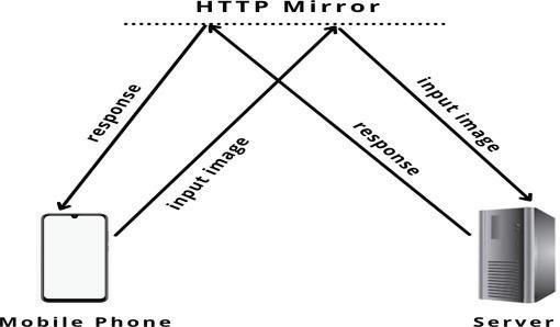
networkeitherusingBluetooth,Wi‐Fi,orotherwire‐lesstransmissionprotocols.
Theonlyrequirementissuf icientbandwidthand lowlatency.Themobileapplicationsendsarequestto themirrorsitewhich,inturn,forwardsittothelocal server.Thelocalserver,runningaYOLOv3model, detectsobjectswithintheinputimageandcreatesa listofobjectsfound.Thislistis inallyconvertedinto astringandsentasaresponsetothemirrorsite, which,redirectstheresponsetotheclientapplication. Theclientapplicationusingtext‐to‐speechfunction‐alityconvertsthisstringintoaudiothatisfedinto theearpieceofthevisually‐impairedindividual.For simplicity,theentireimageisdividedinto9different zones,viz.,Center,TopLeft,BottomRight.Themodel alsopredictsthezoneofeachobjectdetectedusingthe bounding‐boxlocationreturnedbytheYOLOmodel.
Thevariouscomponentsofthesystemareas follows:
‐ YOLOv3:YOLO modelimplementedin Python using CV2 and Numpy libraries.
‐ LocalServer: Serverimplementedin Python using Flask and ngrok libraries.
‐ MobileApplication: MobileApplicationimple‐mentedin Dart and Flutter using Dio, tts,and camera libraries.
‐ HTTP Mirror: Ngrok createsamirror HTTP site thatredirectsandforwardsrequestsandresponses betweenclientandserver.Therequestismadeto thisHTTPsite.
‐ Camera: Externalcameradeviceinstalledonthe walkingcane.
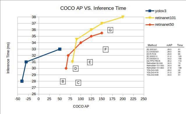

6.1.YOLOv3Metrics(Table 1)

‐ BasedonCOCO’saveragemeanAPmetric,YOLOv3is comparabletoSSDvariants.YOLOv3’sperformance at320x320is22msat28.2mAP,whichis3times fasterthanSSD.
‐ WhenmAPdetectionisupdatedtoIOU=.5(or AP50),YOLOv3hasaperformancealmostsimilarto RetinaNet.AccordingtoRetinaNet’stests,itachieves similarperformanceto57.9AP50in51ms,butitis 3.8*fasterthanRetinaNet’stests.
‐ TheYOLOv3performancedropssigni icantly,as indicatedbyCOCOaverageAP,astheIOUthreshold increases,indicatingthatitisapoorperformer.
‐ However,YOLOv3isaverystrongandfastdetec‐tor,whichisverygoodontheolddetectionmetric of.5IOU
Sincetheapplicationismadeforvisually‐impaired individuals,itisobviousthataveryrudimentaryuser interface(UI)issuf icient.
Basedonthis,wecreatedasimpleandlucidUIthat isbeingusedonlyfordemonstrationpurposes(Refer toFigs.8–10).Theexternalcamerahardwarehasnot beenusedfordemonstrationpurposes,instead,the mobiledevicecameraisused.Afewsamplesofthe ApplicationUIalongwiththelocalserverareshownin Figure11.Themobileapplicationcanbefoundat[25]

andtheserver.Theresponsetimeonaveragewas foundtobearound5s.Theupperboundresponse timeisalsoaround5s.

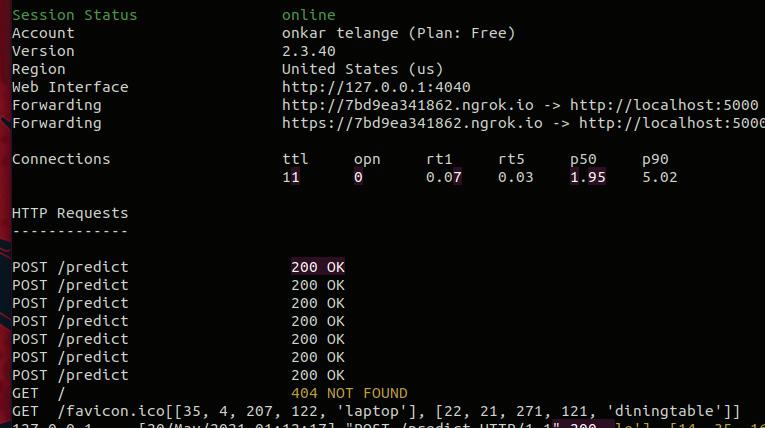
Object‐detectionmodel.ManyObjectDetection algorithmshavebeenproposedwithwide‐scaleappli‐cability.Choosingonesuchmodelthatpertinently solvestheproblemathandisamajordeterminerin obtaininggoodaccuracy.Wehaveprovidedreviewsof variousobjectdetectiontechniquesthatworkwiththe scenicviewofgenericimages.Awide‐scalecompar‐isonamongthevariousobjectdetectorshasencour‐agedustouseYOLOv3,anincrementallymodi ied formofYOLO,astheobjectdetector.Theaccuracy andmAPscoreofYOLOisaboveparwithmostcon‐temporarydetectors,andforanotherreason,YOLOis simplerinimplementation,allowingthesimpleand robustconstructionofanobjectdetector.Wehavedis‐cussedtheproposedarchitecture,i.e.,aclient‐server
modelalongwiththevariousnecessarycomponents. Themodularapproachhasenabledustoachievea greataverageresponsetimeof5s.
Peoplewhoarevisually‐impairedstruggletomove safelyandindependently,whichpreventsthemfrom participatinginroutineprofessionalandsocialactiv‐itiesbothindoorsandoutdoors.Theyalsohavedis‐tressingrecognitionofbasicenvironmentalfactors. Thispaperprovidesacomputervision‐basedsystem thatsupportsblindpeopleinnavigationaswellas triestoaddresstheproblemsposedintheintroduc‐tionsection.Thesuggestedmethodisexaminedunder variouscircumstancesandmeasuredagainstcompet‐ingprogrammesavailableontheAppstore.The ind‐ingsshowthattheprogrammefunctionsreasonably wellundervariousconditionsandisquickerandmore effectivethanitsalternatives.Asopposedtomany otherapplications,thisoneletsblindusersopenit bypluggingtheirmobilephones’earphonejacksin. Thismakesitsomewhataccessibletoblindusers. Thisapplicationcanbeusedfornavigationinitscur‐rentcondition,althoughithasseveralrestrictions. Therearestillalotofthingsthatneedtobe ixed. Toaccountforbetterobjectdetection,theapplication canbeenhancedbycombiningitwiththeInternet ofDevices’technologydevices.Theperformanceof theapplicationwillimproveinthefuturethanksto improvementsindeeplearningandtheYOLOalgo‐rithm.TheapponlyworksonAndroidphones,soit willneedtoberedesignedsothatitcanrunonother platformsaswell.
RatneshLitoriya∗ –Medi‐CapsUniversity,Indore, India,e‐mail:litoriya.ratnesh@gmail.com.
KailashChandraBandhu –Medi‐Caps University,Indore,India,e‐mail:kailashchan‐dra.bandhu@gmail.com.
SanketGupta –Medi‐CapsUniversity,Indore,India, e‐mail:sanket.jec@gmail.com.
IshikaRajawat –Medi‐CapsUniversity,Indore,India, e‐mail:ishika.rajawat30@gmail.com.
HanyJagwani –Medi‐CapsUniversity,Indore,India, e‐mail:email2hany@gmail.com.
ChirayuYadav –Medi‐CapsUniversity,Indore,India, e‐mail:chirayu725@gmail.com.
∗Correspondingauthor
References
[1] WorldHealthOrganization.“Assistivetechnol‐ogy,” WHO,2018.Assistivetechnology(accessed Mar.20,2022).
[2] WorldHealthOrganization.“Blindness andvisionimpairment,” WHO,2021. https://www.who.int/news‐room/fact‐shee ts/detail/blindness‐and‐visual‐impairment (accessedFeb.20,2022).
[3] L.S.Ambati,O.F.El‐Gayar,andN.Nawar.“In lu‐enceofthedigitaldivideandsocio‐economicfac‐torsonprevalenceofdiabetes,” IssuesInf.Syst., vol.21,no.4,2020,pp.103–113,2020.doi: 10.48009/4_iis_2020_103‐113.
[4] C.Guoetal.“Prevalence,causesandsocialfac‐torsofvisualimpairmentamongChineseadults: basedonanationalsurvey,” Int.J.Environ.Res. PublicHealth,vol.14,no.9,2017,p.1034.doi: 10.3390/ijerph14091034.
[5] C.Albus.“Psychologicalandsocialfactorsin coronaryheartdisease,” Ann.Med.,vol.42,no.7, 2010,pp.487–494.doi:10.3109/07853890.201 0.515605.
[6] O.F.El‐Gayar,L.S.Ambati,andN.Nawar. “Wearables,arti icialintelligence,andthe futureofhealthcare,”2020,pp.104–129.doi: 10.4018/978‐1‐5225‐9687‐5.ch005.
[7] P.PandeyandR.Litoriya.“Anactivityvigilance systemforelderlybasedonfuzzyprobability transformations,” J.Intell.FuzzySyst.,vol.36, no.3,2019,pp.2481–2494.doi:10.3233/JIFS‐181146.
[8] P.PandeyandR.Litoriya.“Ensuringelderlywell beingduringCOVID‐19byusingIoT,” Disaster Med.PublicHealthPrep.,vol.16,no.2,2020,pp. 763–766.doi:10.1017/dmp.2020.390.
[9] L.S.Ambati,O.F.El‐Gayar,andN.Nawar.“Design principlesformultipleSclerosismobileself‐managementapplications:Apatient‐centricper‐spective,”2021.
[10] Z.Zouetal.“Objectdetectionin20years:Asur‐vey,”2019.http://arxiv.org/abs/1905.05055.
[11] L.S.AmbatiandO.F.El‐Gayar.“Humanactivity recognition:Acomparisonofmachinelearning approaches,” J.MidwestAssoc.Inf.Syst.,vol.2021, no.1,2021.doi:10.17705/3jmwa.000065.
[12] V.Iyeretal.“Virtualassistantforthevisually impaired,” 20205thInternationalConferenceon CommunicationandElectronicsSystems(ICCES), 2020,pp.1057–1062.doi:10.1109/ICCES487 66.2020.9137874.
[13] R.Saffouryetal.“Blindpathobstacledetector usingsmartphonecameraandlinelaseremit‐ter,” 20161stInternationalConferenceonTechnologyandInnovationinSports,HealthandWellbeing(TISHW),2016,pp.1–7.doi:10.1109/TI SHW.2016.7847770.
[14] A.Mohantaetal.“Applicationforthevisually impairedpeoplewithvoiceassistant,” Int.J. Innov.Technol.Explor.Eng.,vol.9,no.6,2020,pp. 495–497.doi:10.35940/ijitee.F3789.049620.
[15] V.Sharma,V.M.Singh,andS.Thanneeru.“Virtual assistantforvisuallyimpaired,” SSRNElectron.J., 2020.doi:10.2139/ssrn.3580035.
[16] A.M.Weeratungaetal.“ProjectNethra‐an intelligentassistantforthevisuallydisabledto interactwithinternetservices,” 2015IEEE10th InternationalConferenceonIndustrialandInformationSystems(ICIIS),2015,pp.55–59.doi: 10.1109/ICIINFS.2015.7398985.
[17] N.Kumaranetal.“Intelligentpersonalassis‐tant‐implementingvoicecommandsenabling speechrecognition,” 2020InternationalConferenceonSystem,Computation,Automation andNetworking(ICSCAN),2020,pp.1–5.doi: 10.1109/ICSCAN49426.2020.9262279.
[18] V.KepuskaandG.Bohouta.“Next‐generationof virtualpersonalassistants(MicrosoftCortana, AppleSiri,AmazonAlexaandGoogleHome),” 2018IEEE8thAnnualComputingandCommunicationWorkshopandConference(CCWC),2018, pp.99–103.doi:10.1109/CCWC.2018.8301638.
[19] G.Iannizzottoetal.“Avisionandspeech enabled,customizable,virtualassistantfor smartenvironments,” 201811thInternational ConferenceonHumanSystemInteraction(HSI), 2018,pp.50–56.doi:10.1109/HSI.2018.84 31232.
[20] R.G.PraveenandR.P.Paily.“Blindnaviga‐tionassistanceforvisuallyimpairedbasedon localdepthhypothesisfromasingleimage,” ProcediaEng.,vol.64,2013,pp.351–360.doi: 10.1016/j.proeng.2013.09.107.
[21] M.W.Rahmanetal.“Thearchitecturaldesignof smartblindassistantusingIoTwithdeeplearn‐ingparadigm,” InternetofThings,vol.13,2021, p.100344.doi:10.1016/j.iot.2020.100344.
[22] J.Redmonetal.“Youonlylookonce:uni ied,real‐timeobjectdetection,”2016IEEEConferenceon ComputerVisionandPatternRecognition(CVPR), 2016,pp.779–788.doi:10.1109/CVPR.2016.91.
[23] J.‐M.Perez‐Ruaetal.“Incrementalfew‐shot objectdetection,”2020. http://arxiv.org/abs/ 2003.04668
[24] T.‐Y.Linetal.“MicrosoftCOCO:common objectsincontext,”2014,pp.740–755.doi: 10.1007/978‐3‐319‐10602‐1_48.
[25] J.RedmonandA.Farhadi.“YOLOv3:An incrementalimprovement,”2018.doi:arXiv: 1804.02767.