12 minute read
Crimped polymer microfibers produced via electrospinning: A review


Nikolas J. Vostal a a Department of Mechanical Engineering and Material Science University of Pittsburgh, PA, USA
Nikolas Vostal
Nikolas Vostal is a Junior at Pitt studying Materials Science and Engineering who grew up in Plymouth, Michigan. His interests lie in polymer engineering and composite material design, although outside the classroom he is the president of Pitt’s Material Advantage Chapter and a member of the Pitt Squash team.
Significance Statement
Materials with high strength often suffer from poor flexibility and vice versa. Composites reinforced with crimped microfibers can allow excellent flexibility at low strain but high strength at high strain. This work reviews methods to create such fibers by means of electrospinning and their potential applications.
Category: Review Paper Keywords: electrospinning, crimped fibers, polymer microfibers
Abstract
Until recently, the production of small-diameter fibers and other micro-scale materials have been expensive and difficult. However, in recent years electrospinning has become popular as a plausible, cost-effective means of creating microfibers for a number of different applications. It has also been found that by adjusting the setup of electrospinning, it is possible to create patterned microfibers with unusual properties. One possibility is the creation of crimped microfibers whose wavy nature allows them to be extremely flexible until sufficient strain is applied to straighten them. On a large-scale, mats comprising crimped fibers can be used to create materials which can reliably deform and return to their original position. Such properties have applications in many different fields, most notably the biomedical field, where crimped fibers can mimic the wavy collagen fibers found in organic tissue. This article reviews many of the successful methods of producing crimped nanofibers and their current applications.
1. Introduction
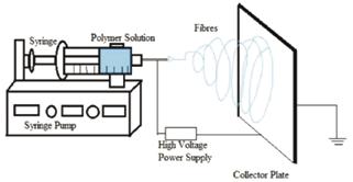
Electrospinning is a simple and versatile method of creating polymeric microfibers. The most basic electrospinning setup utilizes a syringe of polymer solution placed into a syringe pump [1]. The tip of the syringe is electrically charged via a high voltage generator while a nearby metallic collector is grounded. As the solution is slowly pumped out of the syringe, charge builds up around the droplet that forms at the tip of the needle. The built-up charge causes a portion of the droplet to jump across the gap, stretching and drying along its path and hence landing on the collector as a micron-sized fiber [2]. As the pump continues to expel solution, fibers land randomly across the collector, forming a nonwoven mat. While these random mats have found numerous applications, it is also possible to alter the shape and movement of the collector so that fibers land in an oriented fashion with transverse isotropy [3-5]. Aligned fiber mats can be woven to fabricate complex micropatterns that have greater tensile resistance [2].
Figure 1: Diagram of a typical electrospinning setup, Reproduced from Ref 6.
In recent years the concept of using electrospinning to produce crimped microfibers has emerged. The DuPont company first manufactured crimping fibers in the 1960’s using yarnpolypropylene through a process called melt spinning. While these fibers saw a large use in the textiles industry, they were limited in other fields by their large diameter [1]. With the increased use of electrospinning, old techniques are being used alongside new innovations to crimp micron-sized fibers for applications that were once impossible [7].
Crimped fibers are fibers which exhibit a waviness that allow them to flex and unbend before becoming taut and taking on stress [8-9]. On a stress-strain graph this is exhibited as a region of gradual increase in stress at small strains followed by a sharp increase. Most crimped fibers have a sinusoidal waviness but some exhibit a 3-D helical shape. The exact cause of crimping is still debated, but regardless of the shape, crimped fibers seem to form by either imposing external stress on the fiber during spinning or by releasing residual stresses in the fiber after spinning [10-11].
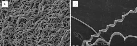
Figure 2: (a) An SEM image of sinusoidally crimped fibers reproduced from Ref 8, and (b) An SEM image of helically crimped fibers, reproduced from Ref 19.
This review seeks to document all reported methods of crimping electrospun fibers and attempts to explain the reasons behind crimping. It also discusses the few current applications of these fibers, although further research into the reliability, mass production, and exact physical properties is needed to truly understand their potential impact.
2. Crimping Methods
Table 1 below offers a quantitative summation of the materials and techniques reviewed. 2.1. Heat Treatment
When fibers are deposited during the electrospinning process, residual stresses may build up in the fibers. These stresses are caused by the whipping and stretching of the fibers when pulled from the needle and how the fibers land upon the collector [12]. In order to release these stresses, fibers can be subjected to temperatures above their glass transition temperature (Tg) [13]. This allows the stresses to relax and expand at different points along the fiber, creating a sinusoidal waviness. The degree of crimp depends upon how much higher the temperature gets above Tg [10].
It has also been shown that by spinning additional sacrificial fibers simultaneously, an interwoven fiber web can be produced. Once the sacrificial fibers are dissolved away, the stress in the remaining fibers leads to greater crimping [14]. A drawback of heat treating is that many polymers will begin to lose their crimp over time [13]. 2.2. Plasticizer Treatment
Much like the thermal treatment, the residual stresses of electrospinning can be released through a plasticizer treatment. This is achieved by taking spun fibers and clamping them at a length shorter than their initial length, inducing slack. The clamp and fibers are then submerged into a plasticizer of the polymer fibers, such as ethanol for polylactic acid (PLA) [15]. The plasticizer is then absorbed by the fibers and allows the polymer chains to release the residual stresses of spinning. This brings the chains to a lower energy conformation, resulting in the formation of crimped fibers [8]. No studies have been conducted concerning the longevity of such fibers: however, it would be interesting to examine the effects on crimping over time after the plasticizer is removed and begins to evaporate. 2.3. Bubble Electrospinning / Bubbfil Spinning
Bubble electrospinning is a novel approach to producing crimped fibers, but few studies have explored it. Bubble electrospinning is different from the previous two examples because crimping occurs during the spinning process, before fibers land on a collector. In bubble electrospinning the syringe and syringe pump are replaced with a reservoir of solution. The entire reservoir is electrically charged and the collector plate is
Material Material % in Solvent
PLA PLLA HSPET/ PTT HSPET/ PAN PU/ PAN PLGA PDLLA P(LLA-CL) PLA coPAA PLA 4.5% in hexafluoroisopropanol 8.5% in hexafluoropropylene 14% in 3:2 TFA/DCM 14% in 3:2 TFA/DCM 13% in DMF 5% in 3:1 DCM/ DMF 5% in 3:1 DCM/ DMF 5% in 3:1 DCM/ DMF DMF 5 and 7% in dry DMF 11% in hexafluoro-2-prpanol Crimp Method Used
Ethanol Treatment Heating Two- Spinneret Compounding Two- Spinneret Compounding Two- Spinneret Compounding Heat Treatment in PBS Heat Treatment in PBS Heat Treatment in PBS Bubble Spinning Heating Ethanol Treatment Crimp Type
Sinusoidal Sinusoidal Helical Helical Helical Sinusoidal Sinusoidal Sinusoidal Sinusoidal Sinusoidal Sinusoidal Reported Spin Voltage (kV)
30 15 15 cm, 1 kV/cm +15 to +22 and -8 to -3 +15 to +22 and -8 to -3 15 cm, 1 kV/cm 15 cm, 1 kV/cm Average Fiber Diameter 600 nm
800 nm
0.82 ± 0.02 µm 0.87 ± 0.03 µm 0.88 ± .002 µm Young’s Modulus, E References
100 ± 22 MPa 300 ± 100 MPa
18 ± 2.5 MPa 14 ± 2 MPa 349 ± 69 kPa
575 ± 200 MPa 15 13 18 & 19 19 19 12 12 14 17 & 20 10 8
placed directly above. At the bottom of the reservoir a gas pump is connected which dispenses compressed gas slowly, allowing bubbles of air to form that float up through the solution. Once the air bubble pops the built-up charge in the solution launches small fibers toward the collector, landing with a sinusoidal crimp [16]. In order to create crimped fibers using this method large transverse vibrations are required in the fibers while they move to the collector. The only successful report of this was by Huang et al, who achieved large enough vibrations by increasing the temperature of the reservoir [17]. It was not stated whether the use of heating during spinning had the same long-term unraveling as other post-spinning treatments. opposing charges cause the fibers to collide midair, forming a compound fiber. The compound fiber then continues horizontally towards the collector due to the remaining charge after the collision [19]. Since this method does not rely on chemical or mechanical post-processing the fibers maintain their crimp much longer than the previously mentioned methods [18].


Figure 3: Diagram of a bubble electrospinning setup.
2.4. Two Spinneret Compounding
The final reported method of crimping electrospun microfibers was by using two separate spinnerets with different polymers and spinning them simultaneously. As the spinnerets eject solution the fibers meet in midair and land together on the collector. The fibers shrink in size before hitting the collector, but because the two fibers shrink at different rates, they curl around each other in a helical pattern [18]. There are a number of publications that have reported producing helical fibers, but the results vary drastically with spin conditions and may form large fiber loops and ribbons instead of crimped waves [19].
The two most successful techniques found differ by spinneret placement. In one method the spinnerets sit side-by-side, while the other places them perpendicular. Side-by-side spinning is the simpler of the two, as both needles can be placed next to each other and carry the same charge [18]. However, for perpendicular electrospinning the fibers must intersect in midair and continue to the collector. This is achieved by inducing the vertical spinneret with a smaller opposing charge to the horizontal spinneret. The
104 Undergraduate Research at the Swanson School of Engineering Figure 4: Diagram of a two-spinneret electrospinning setup, reproduced from Ref 19.
3. Applications
In the biomedical field crimped microfibers are an important innovation for modeling organic tissue, specifically the collagen fiber. Collagen is a naturally wavy microfiber and is a crucial part of many different tissues such as the skin, tendons, ligaments, and veins [20]. The wavy (or crimped) nature of collagen allows tissue to flex and stretch freely within a certain range [21]. Beyond this range, the fibers start to resist strain and become taut [22-23]. Since electrospun fibers act similarly, they have been considered for a number of different supportive and regenerative applications. At this time most of the application research has been centered around using electrospun fibers as regenerative scaffolds. Regrowth of tissue like the anterior cruciate ligament (ACL) after reconstructive surgery can take up to a year [24]. By growing collagen cells on crimped biocompatible fibers replacement collagen fibers can be produced and transplanted in a fraction of the time it takes for the body to regrow naturally [12].
Few other applications have been explicitly explored at this time due to the relative newness and mass production restrictions of these methods [7]. However, crimped fibers have the potential to transform a number of different fields such as air and water filtration, radiation protection, fuel cell electrodes, and flexible electronics [1].
4. Conclusion
Electrospinning is a novel, but versatile process that can be used to create crimped fibers on the micron-scale. This can be accomplished in a number of different methods, including heating, plasticizer treatment, bubble electrospinning, and twospinneret compositing. Regardless of the method intermolecular stresses are used to bend the fibers at different points, forming
crimped sinusoidal waves or 3-D helical shapes. While only briefly explored in the biomedical field as a regenerative scaffold, crimped microfibers have many potential applications. Compared to conventional methods the cost of electrospinning is much lower and its ability to create fibers at small diameters is unparalleled, although scaleup to larger volumes remains challenging. Further research into reliable fibers with larger yields is needed to explore the many diverse applications of crimped microfibers.
5. Acknowledgments
This paper would not be possible without the resources provided by the Swanson School of Engineering and the Office of the Provost. I would also like to thank Dr. Sachin Velankar for his guidance and insight.
6. References
[1] R. Kotek, “Recent Advances in Polymer Fibers”, Polymer Reviews 2008, vol 48, 221-229. [2] Li and Xia, “Electrospinning of Microfibers: Reinventing the Wheel?”, Adv Mater. 2004, vol 16, 1151- 1170. [3] Y Ishii et al. “A new electrospinning method to control the number and a diameter of uniaxially aligned polymer fibers”, Mater. Letters 2008, vol 62, 3370-3372. [4] P Katta et al, “Continuous Electrospinning of Aligned Polymer Microfibers onto a Wire Drum Collector”, Micro Letters 2004, vol 11, 2215- 2218.
[5] K Zhang et al, “Bionic electrospun ultrafine fibrous poly(Llactic acid) scaffolds with a multi-scale structure”, Biomed. Mater. 2009, vol 4, 035004.
[6] Bhattarai et al, “Biomedical Applications of Electrospun Nanofibers:Drug and Nanoparticle Delivery”, Pharamceutics 2019, 11, 5.
[7] W. Teo et al “Technological advances in electrospinning of microfibers”, Sci. Technol. Adv. Mater. 2011, vol 12, 1-19. [8] W. Liu et al, “Generation of Electrospun Microfibers with Controllable Degrees of Crimping Through a Simple, PlasticizerBased Treatment”, Adv. Mater. 2015, vol 27, 2583-2588. [9] S.P. Rwei “Study of Self-Crimp Polyester Fibers”, Polymer Engr. And Sci. 2005, vol 45, 838- 845. [10] L. Peciulyte et al, “Thermal Imidization Peculiarities of Electrospun BPDA-PDA/ ODA Copolyamic Acid Microfibers”, Macromolecular Research 2013, vol 21, 419-426. [11] Demšar & Sluga, “Crimped Polypropylene Yarns”, Kovine Zlitne Tehnologije 1999, vol 33. [12] D. Surrao et al, “Biomimetic poly(lactide) based fibrous scaffolds for ligament tissue engineering”, Acta Biomaterialia 2012, http://dx.doi.org/10.1016/j.actbio.2012.07.012.
[13] D. Surrao et al, “Self-Crimping, Biodegradable, Electrospun Polymer Microfibers”, Biomacromolecules 2010, vol 11, 3624–3629.
[14] Szczesny et al, “Crimped Microfibrous Biomaterials Mimic Microstructure and Mechanics of Native Tissue and Alter Strain Transfer to Cells”, ACS Biomater. Sci. Eng 2017, vol 3. [15] Pavlova et al, “Tuning the properties of electrospun polylactide mats by ethanol treatment”, Materials & Design 2019, vol 181.
[16] R-X Chen et al, “Mini-review on Bubbfil spinning process for mass-production of microfibers”, Revista Mater 2014, vol 19, 325- 344.
[17] JX. Huang et al, “Effect of Temperature on Nonlinear Dynamical Property ...”, Thermal Science 2014, vol 18, 1049- 1053.
[18] B. Zhang et al, “Curled Poly(ethylene glycol terephthalate)/ Poly(ethylene propanediol terephthalate) Microfibers Produced by Side-by-side Electrospinning”, Polymer Journal 2009, vol 41, 252–253.
[19] C. Li et al, “Direct Formation of ‘‘Artificial Wool’’ Microfiber via Two-Spinneret Electrospinning”, Journal of Applied Polymer Science 2011, vol 123, 2992-2995 . [20] JX. Huang et al, “Transverse Vibration of an Axially Moving Slender Fiber of…”, Thermal Science 2015, vol 19, 1427- 1441.
[21] L.J. Gathercole and A. Keller, “Crimp Morphology in the Fibre-Forming Collagens” Matrix 1991, vol 11, 214−234. [22] Franchi et al, “Crimp morphology in relaxed and stretched rat Achilles tendon” Journal of Anatomy 2007, vol 210, 1-7. [23] M.B. Bennett et al, “Mechanical properties of various mammalian tendons” J. Zool 1986, vol 209, 537−548. [24] Mayo Clinic staff, ACL injury, https://www.mayoclinic.org/ diseases-conditions/acl-injury/diagnosis-treatment/drc-20350744, accessed 10/24/2019.


