16 minute read
Department of Bioengineering, Division of Vascular Surgery, University of Pittsburgh Medical Center, Department of Surgery, Department of Cardiothoracic Surgery, and Department of Chemical and Petroleum Engineering, McGowan Institute for Regenerative Medicine, and Center for Vascular Remodeling and Regeneration
Design and manufacture of two experimental test benches for the in vitro assessment of a method to perform in situ fenestration of stent grafts
Nicholas P. Lagermana, Timothy K. Chung, Ph.D.a , Mohammad H. Eslami, M.D.b,c, David A. Vorp, Ph.D.a,b,c,d,e,f,g
aDepartment of Bioengineering, bDivision of Vascular Surgery, University of Pittsburgh Medical Center, cDepartment of Surgery, dDepartment of Cardiothoracic Surgery, eDepartment of Chemical and Petroleum Engineering, fMcGowan Institute for Regenerative Medicine, gCenter for Vascular Remodeling and Regeneration
Nicholas P. Lagerman Nicholas Lagerman is a bioengineering student originally from Reading, Pennsylvania. He is continuing in the field of medical device design because of his love for biology and design.
David A. Vorp, Ph.D. David A. Vorp, PhD, is the Associate Dean for Research at the Swanson School of Engineering. He is a professor of Bioengineering, with secondary appointments in the Department of Cardiothoracic Surgery, the Department of Chemical and Petroleum Engineering, and the Clinical and Translational Science Institute at the University of Pittsburgh.
Significance Statement
There are two primary methods of abdominal aortic aneurysm (AAA) intervention that minimize risk of rupture: open surgery and endovascular aortic repair (EVAR). Fenestrated endovascular aortic repair (FEVAR) is a specialized EVAR procedure that utilizes a patient-specific stent graft to allow blood flow into visceral arteries. Nearly 80% of AAA repairs consist of EVAR or FEVAR [1] as their respective mortality rates are significantly lower than open surgery. FEVAR costs almost 3 times more than standard EVAR and requires substantial time to intervention because a fenestrated stent graft is custom-made for each patient [2]. The ability to create fenestrations in stent grafts during procedures would likely decrease cost and time to intervention. Our work develops two test benches that aid in the development of a novel device for detecting orifices in AAA geometries and creating in situ fenestrations in stent grafts.
Category: Device Design
Keywords: abdominal aortic aneurysm, test bench,
modular perfusion phantom, 3D printing, fiber optic wire, infrared, fenestration.
Abbreviations: Abdominal aortic aneurysm (AAA),
endovascular aortic repair (EVAR), fenestrated endovascular aortic repair (FEVAR), computer-aided design (CAD)
Abstract
This project focuses on the production of two experimental test benches that will be used in parallel towards the development of a novel in situ fenestration device: 1) An in vitro abdominal aortic aneurysm (AAA) phantom to deploy the sensing technology developed in parallel, and 2) A testing block to determine the feasibility of bending fiber optics for the sensing of orifices in the AAA geometry. This was accomplished by designing and generating AAA models, a perfusion chamber, and a fiber optic test block. Three complex geometries (juxtarenal, pararenal, and suprarenal) were modeled using computer-aided design (CAD) software and 3D printed for the perfusion phantom using an elastic resin to simulate the aortic wall’s elasticity. A perfusion chamber to house the models and the connected flow system was designed to allow for the models to be modular. A testing block consisting of fiber optic wire channels with five bending angles and six radii was designed and 3D-printed for the fiber optic test bench. An infrared emitter and receiver circuit with an analog voltage output were placed at opposite ends of the test block to measure the amount of infrared light being transmitted through a fiber optic wire. Both the bend angle (p = 0.135) and bend radius (p = 0.523) tests demonstrated that there was no significant difference in the voltage output between the variations in angles and radii. There is no evidence that the bend radius or angle would influence signaling in the detection of orifices.
1. Introduction
An abdominal aortic aneurysm (AAA) is an enlargement of the abdominal portion of the aorta. Rupture of the aorta may occur if the untreated aneurysm continues to grow in size, and 60% of people will die before reaching the emergency room [3]. To prevent rupture, clinicians usually intervene with one of two: open surgery and endovascular aortic repair (EVAR). There are close to 30,000 AAA repairs that occur annually, and approximately 80% of AAA interventions are EVAR [1] since it is both less invasive and has a lower mortality rate (1.5% compared to 12%) than open surgery [4]. EVAR is performed by inserting a catheter sheath into the femoral artery through a small incision located near the groin [4]. Then a catheter that houses a radially compressed stent-graft is inserted through the sheath. For standard sized grafts, an aneurysm with a minimum neck size of 10 mm (between the aneurysm and renal arteries) is required to properly deploy and anchor the stent-graft to reinforce the vessel wall, whereby preventing rupture [5]. However, there are AAA with complex geometries (juxtarenal, pararenal, suprarenal) which require a specialized fenestrated stent-graft that is deployed and anchored superior to the renal arteries and requires the re-perfusion of blood into the visceral arteries (renal, superior mesenteric artery and celiac) through the use of branching stent-grafts [2]. Therefore, fenestrated endovascular aortic repair (FEVAR) uses a highly customized patient-specific stent-graft to restore blood flow and provide the anchoring needed to prevent migration. There
is only one FDA approved fenestrated stent-graft on the market, the Cook Zenith graft, which requires a minimum of six weeks to create a patient-specific fenestrated stent graft. A potential catastrophic rupture event [5] could occur in this timeframe that requires emergency intervention. Additionally, FEVAR costs up to 3 more times more than EVAR due to customizations of the stent-graft device and technical procedure [2]. To minimize both intervention time and cost, the development of a novel device to identify visceral arteries and fabricate an in situ fenestrated stent graft is essential. A single AAA perfusion phantom was developed by Kung, et al. for the purpose of replicating flow in a AAA model, however it was not designed to accommodate in vitro surgeries [6]. This project focuses on the design of two separate test benches: 1) An in vitro AAA phantom to deploy the sensing technology to be used in the novel device, and 2) A testing block to determine the feasibility and limitations of bending fiber optics for sensing orifices in AAA geometries.
2. Methods
2.1. Modular AAA Perfusion Phantom
Artery Diameter
superior mesenteric artery (SMA) 9 mm [9] common iliac artery 12 mm (normalized) [10]
external iliac artery
8 mm [10]
internal iliac artery renal artery suprarenal aorta
5.5 mm [10]
6 mm [11]
21 mm [13]
infrarenal aorta (affected) 50 mm (juxtarenal, infrarenal) 70 mm (suprarenal)
Table 1: Measurements of diameter in arteries. Measurements found in various journal articles that were used in the modeling of abdominal aortic aneurysms. The infrarenal aorta diameters for each morphology were provided from our clinical expert.
Anatomical Landmarks Distance Between
renal arteries to iliac bifurcation
SMA to renal arteries
130 mm [8]
12.5 mm [9]
iliac bifurcation to internal iliac arteries 45 mm [12]
Table 2: Distances between anatomical landmarks. Average measurements from one anatomical landmark to another that were used in the modeling of abdominal aortic aneurysms of complex geometries.
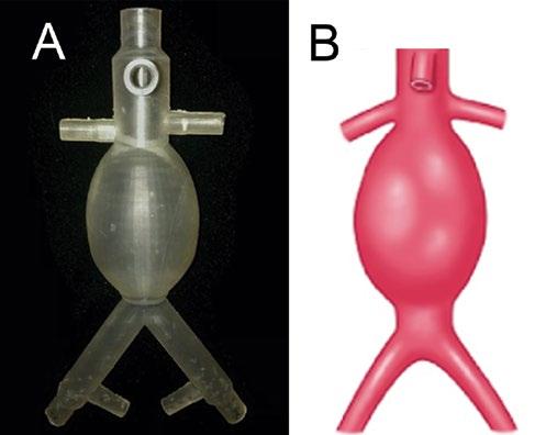
Measurements derived from various research papers on the dimensions of AAA geometries, shown in Table 1 and Table 2, were used in generating three complex geometry AAA models with a wall thickness of 2.5 mm [7,8,9,10,11,12,13]. The three AAA complex geometries were sketched with the measurements from the included tables and modeled using the CAD software SOLIDWORKS (2019, Dassault Systèmes, Vélizy-Villacoublay, France). The openings of each artery were designed to accommodate commercial fittings to allow for easy connection to tubing. The three models were printed in a Formlabs Form 3 SLA 3D Printer (Formlabs, Somerville, MA) using Elastic Resin (Formlabs, Somerville, MA, Cat. # RS-F2-ELCL-01), totaling 24 hours per model. The juxtarenal model is shown in Figure 1. The resin allowed for simulation of the elastic properties of the aortic wall. A perfusion chamber to hold the models and connected flow system was designed in parallel. The components of the box were individually designed and assembled by laser cutting 0.25-inch-thick acrylic sheets. The finalized CAD design for the perfusion chamber is shown in Figure 2. A simple qualitative fluid loss test was performed by connecting the superior aorta opening to a steady-flow pump that passes fluid at a flow rate of 3.15 liters per minute (LPM). Unwanted fluid loss was characterized by fluid exiting the model from areas other than the visceral arteries. A pulse-duplicating flow loop was sourced for the final AAA phantom that has physiologic blood pressure (120/80 mmHg), a flow rate of 3.0 (LPM), and is able heat fluid to body temperature (37oC).
Figure 1: 3D Printed Juxtarenal Model. (A) The juxtarenal AAA model that was the first test print of the design. (B) Sketch of a juxtarenal AAA for comparison to the 3D printed model.
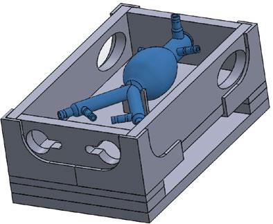
Figure 2: Modular AAA Perfusion Phantom. The final CAD assembly of the perfusion chamber with AAA model to demonstrate positioning.
2.2. Fiber Optic Wire Bend Testing
A testing block, shown in Figure 3, consisting of 1.2 mm diameter wire channels with five bend angles and six bend radii was modeled and printed using non-elastic Formlabs Grey V4 resin. The test block was redesigned using a previous iteration that was developed by a senior design team from the University of Pittsburgh and the pre-existing bend angles and radii were preserved. The following angles and radii were chosen as design constraints because they represent a range of values that can be accommodated in the aorta during deployment of a stent graft. The angles chosen for the testing block were 45° , 60° , 70° , 80° , and 90° , respectively, with a fixed radius of 2 cm. The radii chosen for the testing block were 0.8 cm, 1.2 cm, 1.6 cm, 2.0 cm, 2.4 cm, and 2.8 cm, respectively, with a fixed angle of 90° .
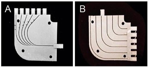
Figure 3: Fiber Optic Bend Test Block. (A) The bend angle side of the test block with included angles of 45, 60, 70, 80 and 90 degrees. (B) The bend radius side of the test block with included radii of 0.8, 1.2, 1.6, 2.0 and 2.4 cm.
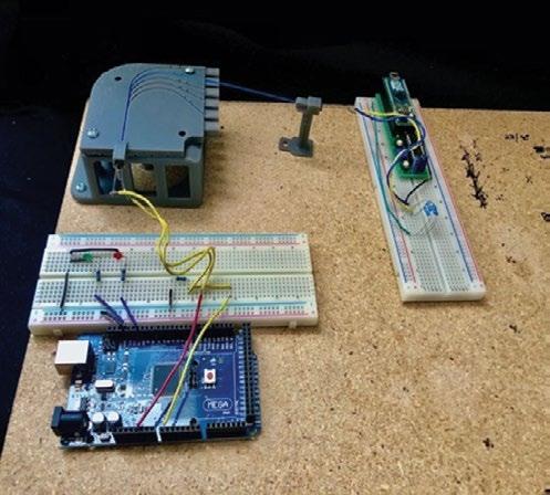
Figure 4: Fiber Optic Bend Testing Setup. Two circuits placed at opposite ends of a fiber optic wire held in place by the test block and an LED holder.
Infrared light was chosen as the wavelength used for sensing; therefore, two separate circuits were developed using an Arduino MEGA (Somerville, MA) microcontroller to send a signal via an infrared emitter and record the signal through a fiber optic wire with a complementary infrared receiver. The circuits were placed at opposite ends of a custom 3D-printed LED holder, shown in Figure 4, consisting of 15 cm of 0.50 Numerical Aperture 400 µm Diameter Core Multimode fiber optic wire (Thorlabs, Newton, NJ) run through the test block channels. A phototransistor (receiver) was attached to the microcontroller to read a continuous stream of analog values that represented voltage changes resulting from intensity changes of the infrared signal received throughout testing. Voltage was the dependent variable because the voltage output of the phototransistor circuit is proportional to the amount of infrared light it receives. A script was coded in MATLAB (2018, MathWorks, Natick, MA) to record the voltage of the receiver circuit. The recorded voltage from signaling periods of 10 seconds was averaged for each bend angle and radius.
3. Results
An in vitro model of an abdominal aorta affected by a complex geometry aneurysm was successfully designed and manufactured. A qualitative fluid loss test demonstrated that the model allowed fluid to pass through continuously without any fluid loss. Additionally, the perfusion chamber that houses the models and flow system was successfully designed and constructed.
3.2. Fiber Optic Wire Bend Tests
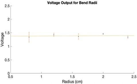
The data acquired during experimentation for each fiber optic wire bend angle and radius is a result of the average of three ten-second continuous voltage readings. Figure 5 displays the voltage data recorded for the various bend angles, and Figure 6 shows the voltage data recorded for the various bend radii. Fiber optic bundles anchored to catheters will be used to detect a point source in the visceral arteries to determine the location of the orifice requiring a fenestration. Two separate one-way analysis of variance (ANOVA) tests were used to determine if there was any significant difference between the means since there were more than two independent groups (five angle groups and six radius groups). One ANOVA was applied to the bend radius dataset and showed no significant difference (p = 0.523). The second ANOVA was applied to the bend angle dataset and showed no significant difference (p = 0.135).
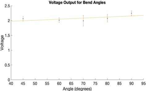
Figure 5: Fiber Optic Bend Angle Data. The voltage outputs of each bend angle plotted with error and a linear trendline to show that there was no change over time. A p-value of 0.523 was calculated for this data.
Figure 6: Fiber Optic Bend Radius Data. The voltage outputs of each bend radius plotted with error and a linear trendline to show that there was no change over time. A p-value of 0.135 was calculated for this data.
4. Discussion
The AAA model demonstrated the ability to allow fluid to pass through it without losing any fluid through its walls. This is critical in maintaining continuous flow in the perfusion phantom since that is the point where loss is most likely to occur. This project will progress with attaching tubing to the openings of the model with fittings that allow for modularity and producing flow through the system with a continuous flow pump. Additional flow tests will be conducted with the final perfusion system to determine if any fluid loss occurs with the addition of more components. The results from the fiber optic wire bend tests (Figure 5 and Figure 6) show that there is no significant difference in the voltage measured while varying the bend angle or radius. We further demonstrated that there is no evidence the bending radius or angle would influence the signal received to detect an orifice. These results suggest that the use of infrared in two fiber optic cables, one for emission and the other for reception, to detect orifices is feasible for use in the novel fenestration device. There is currently no commercially available device that can be used to perform in situ fenestrations in the abdominal aorta [14]. A paper by Le Houérou, et al. provides a method using lasers guided by fluoroscopic imaging to generate in situ fenestrations during pararenal AAA repair procedures [14]. Our work improves upon the work of Le Houérou, et al. because we aimed to develop a method for visceral artery detection without the need for radioactive contrast agents used in fluoroscopic imaging. Additionally, Le Houérou, et al tests the effectiveness of the device on patients, while the AAA phantom we generated allows for use of the device with zero risk to patients. This research is limited because necessary equipment for test bench construction and data collection was not readily available due to a pandemic, resulting in the inability to gather additional numerical characterizations, such as full dimensioning of and flow rates through the phantom. The process of designing and testing the novel fenestration device can further progress past the initial fiber optic tests with functional test benches.
5. Conclusions
The results from the fiber optic bend angle and bend radius test show that there is no significant difference in the voltage outputs of either bend test. Therefore, infrared signaling through fiber optic wire could be used in the orifice detection component of the in situ fenestration device. Future development will incorporate fiber optic bundles to detect a point source in the visceral arteries to ensure proper placement of fenestrations. The future work that our laboratory intends to pursue includes the completion of AAA perfusion phantom that is connected to a pulse-duplicating flow loop, assessment of the effect of blood on bend testing, and development of a novel in situ fenestration device. After a device is fully developed, the time and cost of intervention on complex geometry AAAs will significantly decrease as in situ fabrication of a fenestrated stent graft will be achieved during a single procedure.
6. Acknowledgements
Thank you to the Swanson School of Engineering, the Office of the Provost, and the Department of Bioengineering for funding this research.
7. References
[1] A. Melillo, J. Trani, J. Gaughan, J. Carpenter, J. Lombardi, Assessing trends, morbidity, and mortality in ruptured abdominal aortic aneurysm repair with 9 years of data from the National Surgical Quality Improvement Program, Journal of Vascular Surgery. 71(2) (2020) 423–431. [2] H. Graves, B. Jackson, The Current State of Fenestrated and Branched Devices for Abdominal Aortic Aneurysm Repair, Seminars in Intervent Radiology. 32(03) (2015) 304–310. [3] L. Robertson, S. Nandhra, Laparoscopic surgery for abdominal aortic aneurysm, Cochrane Database of Systematic Reviews. 7 (2016). [4] R. Greenhalgh, Comparison of endovascular aneurysm repair with open repair in patients with abdominal aortic aneurysm (EVAR trial 1), 30-day operative mortality results: randomised controlled trial, The Lancet. 364(9437) (2004) 843–848. [5] N. J. Swerdlow, W. W. Wu, M. L. Schermerhorn, Open and Endovascular Management of Aortic Aneurysms, Circulation Research. 124(4) (2019) 647–661. [6] E. O. Kung, A. S. Les, F. Medina, R. B. Wicker, M. V. McConnell, C. A. Taylor, In Vitro Validation of Finite-Element Model of AAA Hemodynamics Incorporating Realistic Outlet Boundary Conditions, Journal of Biomechanical Engineering. 133(4) (2011).
[7] K. van den Hengel, Variation in wall thickness in healthy AA and AAA’s, in: Abdominal aortic wall thickness and compliance. (2008) 6–7. [8] M. Kapil dev, V. Vimala, Morphometric Analysis of Distance of Origin of Renal Artery from Bifurcation of Abdominal Aorta for Interventional Procedures, Journal of Dental and Medical Sciences. 18(4) (2019) 66–68. [9] Part I: Anatomy, Acta Radiologica: Diagnosis. 11(s306) (1965) 9–71. [10] İ. Selçuk, B. Uzuner, E. Boduç, Y. Baykuş, B. Akar, T. Güngör, Step-by-step ligation of the internal iliac artery, Journal of the Turkish-German Gynecol Association. 20(2) (2019) 123–128. [11] M. Mohiuddin, A. Mansoor, M. Ali, N. Hassan, Analysis of renal artery morphometery in adults: A study conducted by using Multidetector computed Tomography Angiography, Pakistan Journal of Medical Sciences. 33(4) (2017). [12] R. Lorbeer, A. Grotz, M. Dörr, H. Völzke, W. Lieb, J.-P. Kühn, B. Mensel, Reference values of vessel diameters, stenosis prevalence, and arterial variations of the lower limb arteries in a male population sample using contrast-enhanced MR angiography, PLOS One. 13(6) (2018). [[13] J.H. Joh, H.-J. Ahn, H.-C. Park, Reference Diameters of the Abdominal Aorta and Iliac Arteries in the Korean Population, Yonsei Medical Journal. 54(1) (2013) 48. [14] T. Le Houérou, D. Fabre, C.G. Alonso, P. Brenot, R. Bourkaib, C. Angel, M. Amsallem, S. Haulon, S. (2018). In Situ Antegrade Laser Fenestrations During Endovascular Aortic Repair. European Journal of Vascular and Endovascular Surgery. 56(3) (2018) 356–362.


