6 minute read
Furnaces: Sefpro

Electrical boosting on refractories
Stephane Schaller*, Michel Gaubil*, Isabelle Cabodi** and Pierrick Vespa** discuss how the increased use of higher electrical boosting in furnaces could impact refractories. Using numerical simulation, they found increasing the share of electrical boosting will have an effect on soldier blocks’ corrosion.
In alignment with their commitment to reduce energy consumption and environmental footprint, glassmakers are accelerating the transformation of their production tools to reach carbon neutrality. Depending on the market, type of furnace, glass quality requirements and the local availability of alternative energy sources to replace fossil fuels, the industry is seeking to increase the energy efficiency of furnaces and exploring new melting technologies.
High electrical boosting could be used in multiple furnaces to decrease fossil fuel consumption and CO2 emissions. Recent trends suggest the proportion of electrical power in the energy mix of furnaces will increase in years to come (super boosting, hybrid furnaces…) and several glassmakers have switched to fully electrical furnaces.
Corrosion of refractory materials
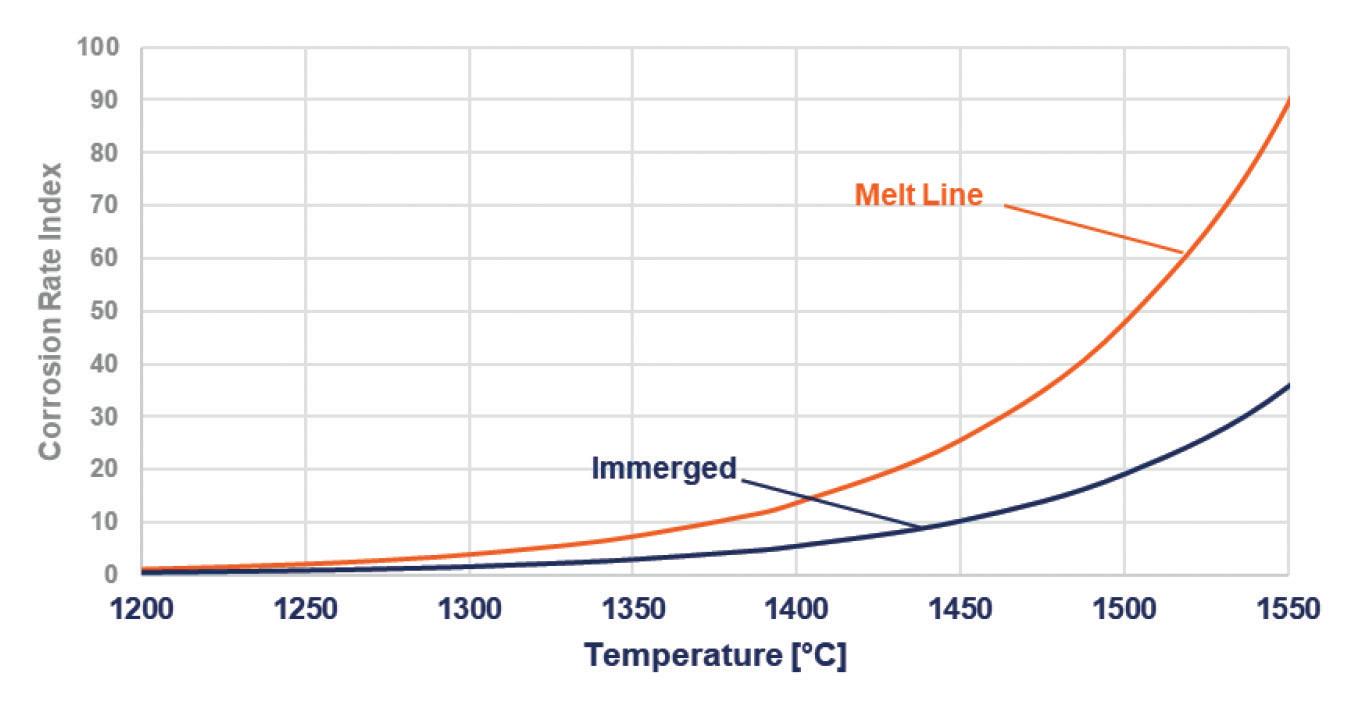
An increased electrical energy share in glass furnaces leads to an increase in glass temperature and velocity in the lower part of the glass bath. Such changes will have a significant effect on the corrosion of tank refractories. Thanks to an extensive database of dynamic corrosion tests results, and industrial experience and measurements, SEFPRO was able to establish specific corrosion laws, linking the corrosion rate of refractories in contact with glass with the temperature of the interface between the glass and the refractory material (Fig 1).
The mentioned corrosion laws were then included in a broader 2D simulation model allowing to estimate the corrosion of sidewalls in glass furnaces. The model results were then validated through studies and collaborations with glassmakers, using industrial data (hook measurements, 3D scans) for different furnace architectures (end-fired, crossfired, cold-top), glass types (sodalime, opal, borosilicate) and refractory materials. The developed numerical tool could assess the modifications in refractory materials corrosion when varying their operational environment (glass temperature and distribution, insulation, air cooling).
The following results assess the effect of high electrical boosting in a given configuration (adapted from sodalime end-fired furnaces) and their consequences on industrial operations and lifetime.
Numerical simulation of soldier blocks’ corrosion
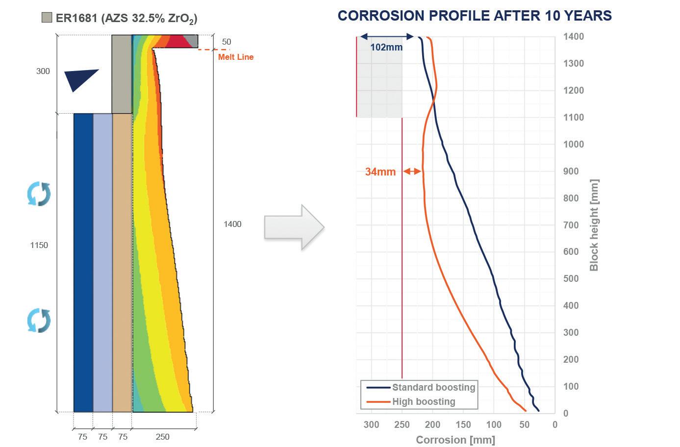
According to simulation results, modifications of the glass bath’s properties due to electrical boosting leads to a change in the corrosion profile of the soldier blocks (Fig 2).
In standard conditions, the critical corrosion point is located at the melt line. The usual way to manage soldier block corrosion during campaign is to apply a patching tile on the top part of the block and pursue operations.
In the case of high electrical boosting, with the evolution of glass – refractory interface temperature profile, the critical corrosion point is shifted toward the bottom of the block. After some time, a new critical point is located at about midheight of the block, below the area covered by the typical patching tiles, leading to a final refractory thickness of 34mm after 10 years of campaign, as illustrated in Fig 3, for the applied parameters of this specific study.
Such changes in blocks’ corrosion highlight the necessity to adapt furnace design or maintenance strategy to maintain safe refractory thickness at sidewalls during operations. Both scenarios are simulated hereafter.
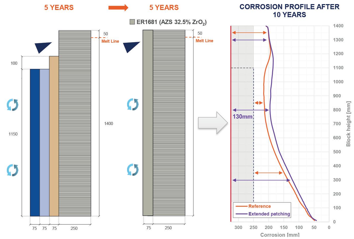
Scenario 1: Applying a larger patching tile during maintenance, covering the entire height of the block and removing insulation layer behind, allows to reach the 10-year lifetime target with a safe refractory thickness on the entire height of the block (Fig 4). Nevertheless, removing the insulation
Continued>>
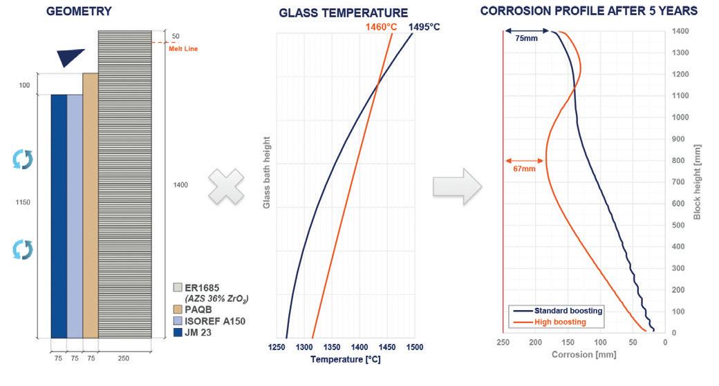
� Fig 1. Corrosion behaviour of ER 1685 RR AZS in sodalime glass. � Fig 2. Effect of glass temperature profile on soldier block corrosion after 5 years
� Fig 3. Effect of glass temperature profile on soldier block corrosion after 10 years. � Fig 4. Application of a larger patching tile & insulation removal.
� Fig 5. Improved initial design with 350mm, ER 1711 RT void-free block & reduced insulation.
in the bottom part of the block results in an increase in thermal losses for a total of 855 MWh/m² over the 10 years of operations in the study’s calculation conditions. The additional losses will need to be balanced by increasing energy consumption and, therefore, operational costs and CO2 emissions.
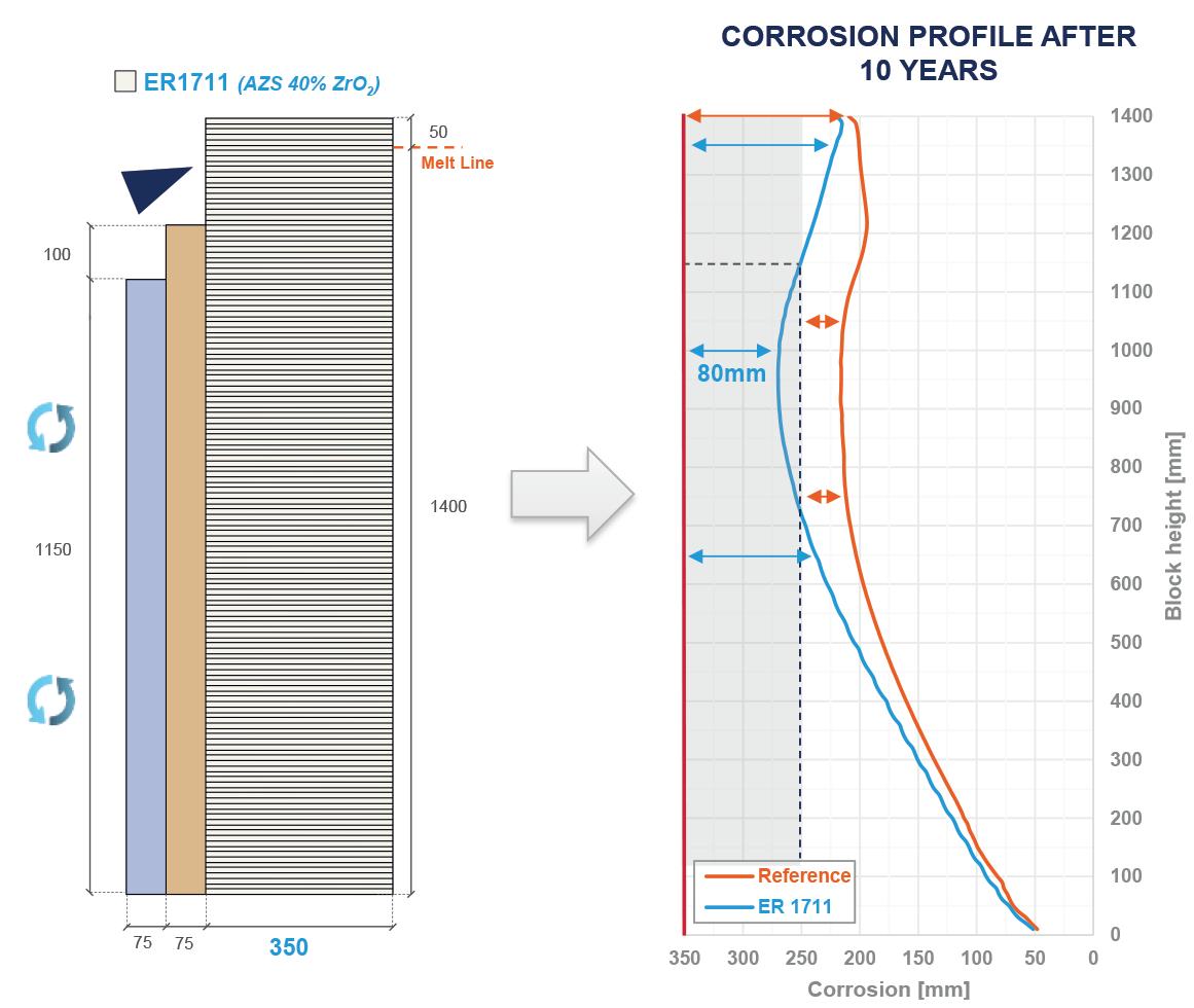
Scenario 2: A second option to increase lifetime of the soldier block assembly consists in modifying the initial design of the block. The example presented here (Fig 5) shows a thicker block (350mm vs 250mm), made of a higher AZS grade and void-free casted. The initial insulation package is also reduced by removing the third layer present in the initial design. The final residual thickness at the critical corrosion after 10 years is safe (80mm). Moreover, by running the entire 10-year campaign, keeping insulation layers, thermal losses are reduced by 66% (292 MWh/m²) compared to Scenario 1 (855 MWh/m).
The simulation of this specific case highlights the importance of optimised initial design, specifically regarding insulation and block size. A well-designed insulation package kept for the entire lifetime of the furnace appears to be more efficient than running a bare block after over insulating during the first part of the campaign.
Finally, high electrical boosting corrosion profiles point out that the use of a void-free block is mandatory to reduce the effect of shrinkage cavity on the corrosion rate.
The corrosion model presented does not account for the effect of shrinkage cavity on corrosion rate. The actual corrosion of partially filled (RN or RR) refractory blocks during operations might therefore be higher than anticipated, specifically in the bottom part of the block.
Choosing blocks exhibiting improved filling (RT or RS) would lead to increase safety of operations and improved agreement between simulation results and actual wear of the refractories.
Conclusions
Industrial measurements and numerical simulation show that increasing the share of electrical boosting inside glass furnaces will have a significant effect on soldier blocks’ corrosion. It typically translates in the emergence of a second critical corrosion point located lower in the height of the block.
The simulation performed on a fictional sodalime furnace shows that modifications are necessary to maintain the lifetime of the furnace’s tank. Two examples were presented, allowing in both cases to reach the same lifetime as the reference (10 years). For the first case, the same initial design is considered and the maintenance strategy is adjusted. By applying a larger patching tile, covering the entire height of the block and removing the insulation behind, the targeted lifetime is achieved with safe residual thickness at every point of the block. However, the insulation removal necessary to apply the overcoating leads to an increase in thermal losses, reaching a total of 855 MWh/m² after 10 years.
The second approach allows to maintain an insulation package for the entire campaign, leading to total thermal losses of 292 MWh/m². Thanks to the modification of the soldier block’s design (thicker block, higher zirconia content, void-free product), the bottom of the block is secured while offering a 66% reduction in specific thermal losses compared to the previous case.
The cases studied represent only two options among the vast range of possible alternative designs. Every furnace being unique, SEFPRO can provide calculations for specific sets of operating conditions to reach the best compromise between energy losses, investment cost and furnace lifetime. �
*SEFPRO, France, www.sefpro.com **Saint-Gobain Research Provence