
Seismic/ Wind INSIDE: Seismic Rehab of Oregon Capitol 26 Preserving a 1960s-era Arena 30 Oakland's Tapscott Building 36 Brooklyn Powerhouse 42 STRUCTURE MARCH 2024 NCSEA | CASE | SEI


YOUR NMB Splice Sleeve System RebarSplicing MechanicalCouplers CAST-IN-PLACERebarSplicing MechanicalCouplers


subscriptions@structuremag.org
EDITORIAL BOARD
Chair John A. Dal Pino, S.E.
Claremont Engineers Inc., Oakland, CA chair@STRUCTUREmag.org
Marshall Carman, P.E., S.E. Schaefer, Cincinnati, Ohio
Erin Conaway, P.E. AISC, Littleton, CO
Linda M. Kaplan, P.E. Pennoni, Pittsburgh, PA
Nicholas Lang, P.E.
Vice President Engineering & Advocacy, Masonry
Concrete Masonry and Hardscapes Association (CMHA)
Jessica Mandrick, P.E., S.E., LEED AP
Gilsanz Murray Steficek, LLP, New York, NY
Jason McCool, P.E.
Robbins Engineering Consultants, Little Rock, AR
Brian W. Miller
Cast Connex Corporation, Davis, CA
Evans Mountzouris, P.E. Retired, Milford, CT
Kenneth Ogorzalek, P.E., S.E.
KPFF Consulting Engineers, San Francisco, CA (WI)
John “Buddy” Showalter, P.E. International Code Council, Washington, DC
Eytan Solomon, P.E., LEED AP Silman, New York, NY
Jeannette M. Torrents, P.E., S.E., LEED AP JVA, Inc., Boulder, CO
EDITORIAL STAFF
Executive Editor Alfred Spada aspada@ncsea.com
Managing Editor Shannon Wetzel swetzel@structuremag.org
Production production@structuremag.org MARKETING
Director for Sales, Marketing & Business Development
Monica Shripka
Tel: 773-974-6561 monica.shripka@STRUCTUREmag.org
3 MARCH 2024 ADVERTISER index Please support these advertisers Allplan 4 Anthony Forest Products | Canfor 23 ASDIP Structural Software ..................................... 7 Computers & Structures, Inc. Back Cover DEWALT-Stanley Black & Decker ...................... 40 DuraFuse Frames 3 Enercalc 8 ICC-ES .......................................................................... 41 Keller Inside Back Cover NCEES ......................................................................... 53 Nucor 10-11 Nucor-Vulcraft/Verco Decking 25 RISA ............................................................................. 15 Simpson Strong-Tie 6 Splice Sleeve ........................... Inside Front Cover Subsurface Constructors, Inc. 19
® CIRCULATION
STRUCTURE
& ADVERTISING
SALES
STRUCTURE magazine (ISSN 1536 4283) is published monthly by The National Council of Structural Engineers Associations (a nonprofit Association), 20 N. Wacker Drive, Suite 750, Chicago, IL 60606 312.649.4600. Periodical postage paid at Chicago, Il, and at additional mailing offices. STRUCTURE magazine, Volume 31, Number 1, © 2024 by The National Council of Structural Engineers Associations, all rights reserved. Subscription services, back issues and subscription information tel: 312-649-4600, or write to STRUCTURE magazine Circulation, 20 N. Wacker Drive, Suite 750, Chicago, IL 60606.The publication is distributed to members of The National Council of Structural Engineers Associations through a resolution to its bylaws, and to members of CASE and SEI paid by each organization as nominal price subscription for its members as a benefit of their membership. Yearly Subscription in USA $75; $40 For Students; Canada $90; $60 for Canadian Students; Foreign $135, $90 for foreign students. Editorial Office: Send editorial mail to: STRUCTURE magazine, Attn: Editorial, 20 N. Wacker Drive, Suite 750, Chicago, IL 60606. POSTMASTER: Send Address changes to STRUCTURE magazine, 20 N. Wacker Drive, Suite 750, Chicago, IL 60606. STRUCTURE is a registered trademark of the National Council of Structural Engineers Associations (NCSEA). Articles may not be reproduced in whole or in part without the written permission of the publisher. Digital Issue Available Only at STRUCTUREmag.org March 2024 ADVERTISEMENT–For Advertiser Information, visit STRUCTUREmag.org
Buildable steel connections for smarter structures.
SDS2 steel detailing software offers unparalleled intelligence when it comes to steel connection design, delivering fabricationand erection-ready connections automatically to ensure smart, cost-effective structures you can deliver with speed and accuracy.

SDS2 2024 AVAILABLE NOW WITH AISC 16TH EDITION & CISC 12TH EDITION UPDATES
Model by Mold-Tek Technologies
SEE IT FOR YOURSELF REQUEST A DEMO TODAY sds2.com
\ Gillette Stadium North Endzone Renovation
MARCH 2024
SEISMIC REHAB OF THE OREGON STATE CAPITOL
By John McDonald, S.E., Stefanie Chamorro, P.E., and Geoff Bomba, S.E.
The Oregon State Capitol Renovation project seismically retrofits and renovates multiple structures utilizing ASCE 41. Cover photo courtesy of PngStudio.

PRESERVING A LANDMARK
By

30
Brian MacRae, P.E., S.E.,Kerem Gulec, Ph.D., P.E., S.E.

Using performance-based seismic design, the structural engineering team retrofitted the existing venue while maintaining the original 1960s feel.
BROOKLYN POWERHOUSE
By Eytan Solomon P. E., LEED AP, and Richard Lo P. E
42
Powerhouse Arts in Brooklyn, New York is a $180 million adaptive reuse project that included extensive renovation and new construction—culminating in 170,000 square feet for fabrication shops, educational facilities, community programs, and multi-functional event space.
36
REVITALIZING OAKLAND’S BEAUX-ARTS TAPSCOTT BUILDING
By Zack Kardon P.E. and Viral Vithalani, AIA
A vacant structure returns as a functional portion of downtown while maintaining its historic appeal.
48
BEHIND THE SCENES OF STRUCTURAL ENGINEERING RECONNAISSANCE EFFORTS
By Robert K. Dowell, Gulen Ozkula, Jui-Liang Lin, Tunc Deniz Uludag, and Ayse Hortacsu
A team of structural engineers investigated the aftermath of the for the Mw 7.8 and Mw 7.5 Türkiye (Turkey) Earthquakes of February 6, 2023.
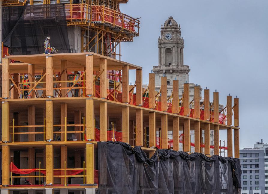
Tall mass timber shows its potential in 1510 Webster Street. 54
A NEW HOPE FOR HOUSING
By Jeff Brink and Michael Bauer
FEATURES Contents
26 Cover Feature
Slide a smarter cladding system into place.
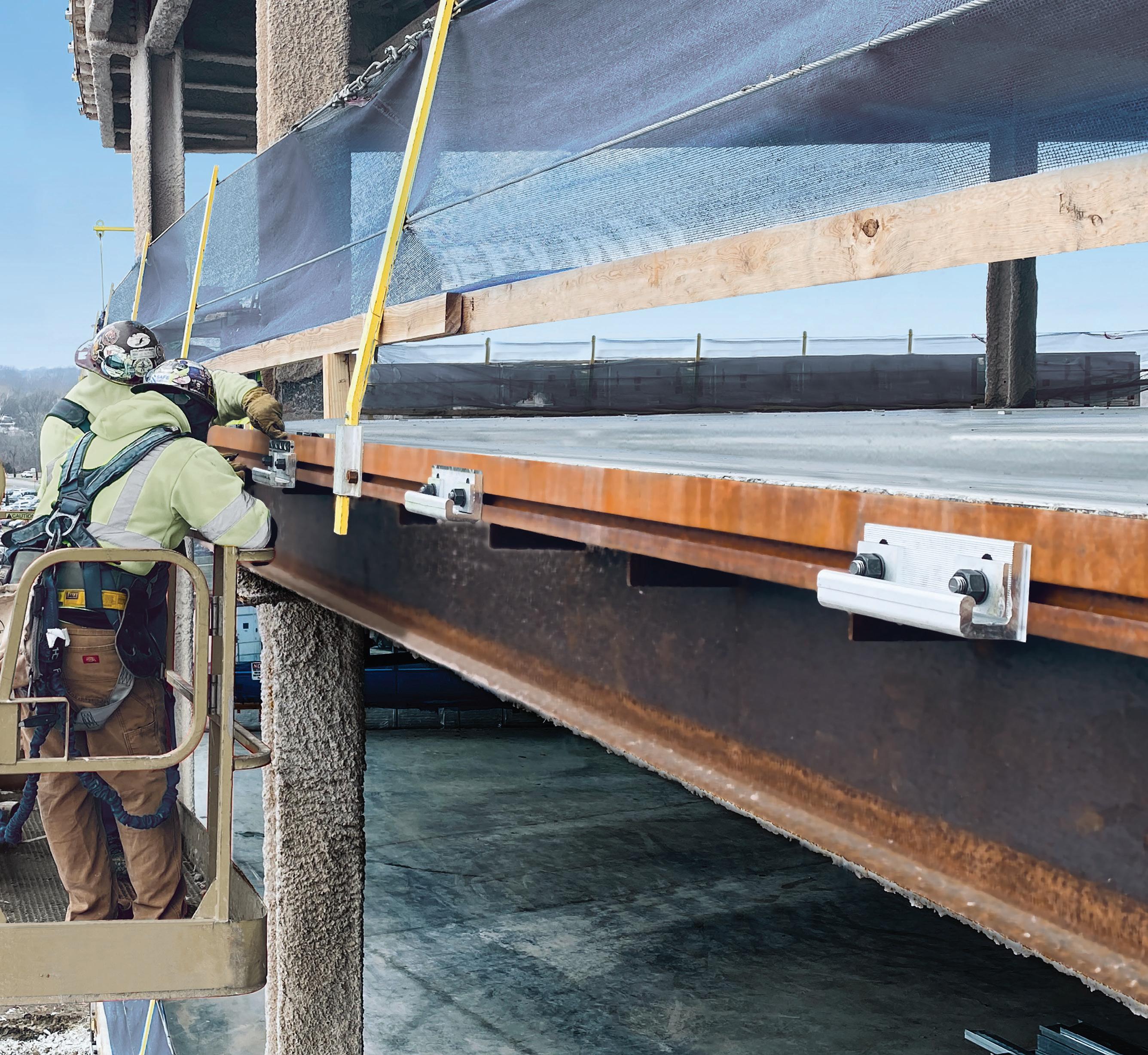
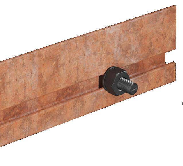
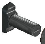
Specify cladding and curtain-wall connections with the new Edge-Tie™ system from Simpson Strong-Tie. Designed with a unique, extruded shape and pour stop, it provides two times the load capacity of traditional bent plates. This innovative solution utilizes bolts that allow installers to easily position and adjust anchors along a continuous slot. By eliminating field welding, the Edge-Tie system speeds up building enclosure while saving time and labor costs. It’s simply a smarter, faster way to get the job done.
Engineer your next project with all of our structural steel solutions. To learn more, visit go.strongtie.com/edgetiesystem or call (800) 999-5099.
The Edge-Tie™ System
© 2024 Simpson Strong-Tie Company Inc. M-LS-ETS22-S Structural Steel Solutions | Products, Software and Service for Smarter Building
MARCH 2024 7 Publication of any article, image, or advertisement in STRUCTURE® magazine does not constitute endorsement by NCSEA, CASE, SEI, the Publisher, or the Editorial Board. Authors, contributors, and advertisers retain sole responsibility for the content of their submissions. STRUCTURE magazine is not a peer-reviewed publication. Readers are encouraged to do their due diligence through personal research on topics. COLUMNS and DEPARTMENTS In Every Issue 3 Advertiser Index 64 SEI Update 66 CASE in Point 68 NCSEA News 71 Resource Guide – Concrete 22 59 12 72 Structural Forum Understanding Developing Issues in Access to Design Data Part 2 By Joan Malana Kennedy 74 Structural Forum Shaking News! Myths in Seismic Design By Matt Barnard 70 Engineer's Notebook Finding Fun in Structural Engineering By John A. Dal Pino 59 Code Updates 2024 IBC Significant Structural Changes By John “Buddy” Showalter, P. E., M. ASCE, M. NCSEA, and Sandra Hyde P. E., M. ASCE, M. NCSEA 22 Structural Analysis Special Wind Zones in Washington and Oregon By Seth Thomas 20 Structural Design Watch Out for Unevenly Loaded Welds Part 2 By Duane K. Miller 16 Structural Design Declaring Independence By Kyle A. Karschner P.E., S.E., Jacob Sun, P.E., and Michael F. Hughes, P.E., S.E. 14 Structural Design Seismic Response Factor in ColdFormed Steel Flat Strapped Lateral Systems By Timothy R. Donahue, P.E. 12 Structural Design Residual Drift—The Ignored Outcome By John Worley, S.E. and Pierre Quenneville, Ph.D 9 Editorial Leading the Way in Sustainability and Resilience in Structural Engineering By Jerome F. Hajjar, Ph.D., P.E., NAE, F.SEI, F.ASCE ADVERTISEMENT–For Advertiser Information, visit STRUCTUREmag.org


Leading the Way in Sustainability and Resilience in Structural Engineering
By Jerome F. Hajjar, Ph.D., P.E., NAE, F.SEI, F.ASCE
Theconstruction and operation of the built environment accounts for a large portion of global greenhouse gas emissions. Governments, owners, occupants, architects, and engineers increasingly recognize the centrality of the structural engineering profession in our collective efforts to mitigate climate change. The United Nations (UN), through the Conference of Parties (COP) yearly intergovernmental summit aimed at creating global cooperation on issues of mitigating climate change, met in December 2023 in Dubai for COP28, at which they continued development of a Breakthrough Agenda
According to the UN Environment Program, the Breakthrough Agenda “provides a framework for countries, businesses and civil society to join up and strengthen their actions every year in key emitting sectors, through a coalition of leading public, private and public-private global initiatives.” The Breakthrough Agenda is focused heavily on areas central to structural and civil engineering, including Power, Road Transport, Steel, Buildings, and Cement & Concrete, with the latter two recently adopted following COP28.
COP28 and the Breakthrough Agenda
The Breakthrough Agenda goals are ambitious, and our structural engineering expertise is indispensable in achieving them. The world’s leading carbon producing countries are committing to netzero greenhouse gas emissions, with the United States and the European Union pledging to reach the goal by 2050, China following a decade later, and India committing by 2070. In addition, the United States has committed to reducing U.S. greenhouse gas emissions by over 50% from 2005 levels by 2030 and achieving carbon pollutionfree electricity by 2035. The White House has highlighted major U.S. steel and cement companies’ commitments to net-zero emissions no later than 2050.
Structural engineers are increasingly taking a lead in achieving these goals through research and design innovations that:
• Reduce the quantities of materials needed for construction.
• Enable the reuse of components at the end of the life of a structure.
• Utilize recycled materials made with electricity obtained from renewable resources.
• Adopt fabrication and construction practices that use electricity instead of fossil fuel for transportation and on-site power.
• Conceive of novel structural solutions for resilience in the face of natural disasters increasingly driven by climate change.
The Structural Engineering Institute as a Leader in Sustainability and Resilience
The Structural Engineering Institute (SEI) is especially well positioned to take broad leadership in addressing sustainability and resilience in the built environment. We are always looking for leaders, partners, and innovators to help drive forward new solutions. Throughout SEI and the American Society of Civil Engineers (ASCE), there are numerous efforts to address climate change and its impact on the built environment, including Resilience and Sustainability Committee efforts, and the publication of the new ASCE/COS 73-23: Standard Practice for Sustainable Infrastructure
Within SEI, the Technical Committee on Sustainability is leading several outstanding initiatives, including producing major reports on Whole Building Life Cycle Assessment: Reference Building Structure and Strategies, and Structural Materials and Global Climate: A Primer on Carbon Emissions for Structural Engineers; as well as spawning the SE2050 initiative. As the lead organization for the SE2050 initiative, SEI members are working with companies to foster commitments to incorporating sustainable design into their practice and providing technical information and education forums to foster sustainable design.
In addition, a Future Conditions Subcommittee has been formed within the standards committee that produces ASCE/SEI 7 Minimum Design Loads and Associated Criteria for Buildings and Other Structures. The subcommittee is developing a plan to address climate change within the ASCE 7 standard, a crucial step forward within our profession.
A New Paradigm in Structural Engineering Education
In addition to the evolutions required in our practice, it is important to consider

integration of sustainability and resilience in our higher education programs. There is increasing recognition that our emphasis in structural engineering education is starting to shift, as programs adopt new courses and degree programs related to repair, retrofit, and rehabilitation of structures; addressing embodied carbon as a key design objective; and considering resilient design strategies for structures. Industry is seeking new talent trained to meet climate-related engineering challenges, and today’s students are vocal in their desire to study and address these issues.
New Framework for Structural Design
It is my hope that sustainability and resilience become premier design objectives within our profession, underpinned by our current design objectives that address safety, serviceability, constructability, aesthetics, and economy. Achieving ubiquitous sustainable and resilient structural designs will take more than technical innovation. It will require an evolving mindset within the profession and the public. We can each take steps to accelerate this transformation through continuing to learn about and adopt structural systems and practices that are more sustainable and resilient, and advocating for these designs within the profession and to the public.
Representing one of the largest structural engineering organizations and publishers of structural engineering information in the world, the Structural Engineering Institute continues to take the lead in partnering with other organizations worldwide to address global opportunities for fostering sustainable and resilient structural design. For those interested in participating in such activities, I encourage you to join the SEI efforts underway, initiate new SEI efforts, and attend forums and conferences in which SEI is a host or partner organization—www.asce.org/SEI . Together we can develop the vital solutions required to address sustainability and resilience in structural engineering.■
STRUCTURE magazine MARCH 2024 9
EDITORIAL
Jerry Hajjar is CDM Smith Professor and Chair of the Northeastern University Department of Civil and Environmental Engineering, and President of SEI.










high-strength steel is enabling sustainable design. nucor.com/madeforgood
See how
structural DESIGN
Residual Drift—The Ignored Outcome
Mitigating residual drift following an earthquake can help maintain the vitality of affected buildings and avoid demolition.
By John Worley, S.E. and Pierre Quenneville, Ph.D
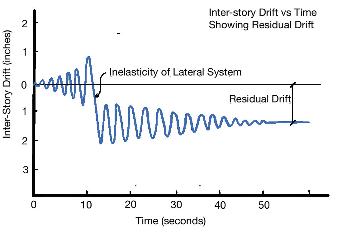
“Residual drift” is the permanent lateral deformation of a building following an earthquake (Figure 1). In high seismic regions, buildings designed per code utilizing ductile seismic force resisting systems defined in ASCE 7 could experience excessive residual drifts in a major earthquake that may result in a damage level deemed to be uneconomical to retrofit and therefore be demolished. Most ductile lateral systems rely on yielding fuse elements to protect other elements of the structure, but the inelasticity of these elements can lead to significant residual drifts in a major earthquake as shown in Figure 2. The building’s lateral force resisting system may have performed exactly as intended by code design (to not collapse and to preserve life safety), but the residual drift can have a huge negative impact on the building owner and occupants. During design, building owners are often unaware of the potential residual drift that could occur with a code-designed structure and the resulting ramifications. It is important for structural engineers to understand residual drift and to inform building owners of the potential residual drift that could occur with a basic code-designed lateral system and offer design enhancements that can help mitigate residual drifts.
U.S. building codes do little to limit residual drift. For new building design per ASCE 7-22 there are no residual drift limits for buildings less than 240 ft. in height, and a large 1% residual drift limit is imposed for buildings taller than 240 ft. if a non-linear response history analysis is utilized. For seismic retrofit of existing buildings per ASCE 41 there are no residual drift limits. Residual drift limits are not prescribed in the building code for two main reasons. First, the focus of the code is on life safety and collapse prevention in a major earthquake. Residual drift is not seen as a threat to these if other code requirements are satisfied, including the transient drift limits. Second, a more complex non-linear time history analysis is required to calculate the residual drift that often is not used in design and even then, it is difficult to accurately calculate. FEMA P-58-1 (Seismic Performance Assessment of Buildings) acknowledges the difficulty of calculating residual drifts with standard non-linear analyses and provides a method

of estimating residual drift based on the transient story drift. Although the code does not put limits on residual drift, it is important for engineers to understand the level of residual drifts that could occur for a given lateral system and to convey to building owners the potential for these residual drifts in a major earthquake and the corresponding ramifications. Building owners that value the useability of their building following a major earthquake may choose a higher level of performance that limits residual drift. Designing to mitigate residual drift not only provides value to building owners, it is also one of the most effective things a structural engineer can do to contribute to the sustainable design of a project. A building that must be demolished following an earthquake is extremely unsustainable. For example, after the New Zealand Christchurch earthquake, buildings with residual drifts greater than 0.5% were deemed to be uneconomical to retrofit leading to the demolition of over 2,700 buildings in the central business district. This was not only a huge impact on building owners and occupants but on the entire community of Christchurch. Studies by Erochko et al. 2011 and McCormick et al. 2008 found that residual drifts over 0.5% can lead to damage that is uneconomical to retrofit, leading to building demolition. Unfortunately, new building designs that adhere to all the requirements of the code can exhibit residual drifts of more than 0.5% in a major earthquake and therefore may be rendered uneconomical to retrofit and demolished following a major seismic event.
Listed below are a few design enhancements that can help mitigate residual drift with some of these being more effective than others.
• Utilize steel or concrete moment frames along with viscous dampers to reduce a structure’s earthquake response and therefore reduce residual drift. Figure 3 shows viscous dampers in braces. This system can be effective in mitigating residual drift if the moment frames stay within their elastic range while being stiff enough to provide the restoring force to recenter the structure. Depending on the analysis method and jurisdiction, this enhancement may require a design peer review.
• Utilize braced frames or shearwalls along with backup moment frames to provide a post yield
STRUCTURE magazine 12
Figure 2. A plot of inter-story drift versus time shows the residual drift.
Figure 1. This figure illustrates residual drift on a structural frame.
stiffness and to provide a restoring force that reduces the amount of residual drift. This system can be effective in mitigating residual if the moment frames are kept in their elastic range while being stiff enough to provide a restoring force necessary to recenter the structure. The brace frames or shearwalls rely on element yielding and these elements may need to be repaired following a major earthquake.
• Utilize a rocking lateral force resisting system that employs gravity and/or post-tensioning to provide a restoring force that helps recenter the structure. Figure 4 shows a simple diagram of rocking shearwall. This system can be effective in reducing residual drifts. Rocking systems typically have ductile yielding elements which may require repair following a major earthquake. Depending on the analysis method and jurisdiction, this enhancement may require a design peer review.


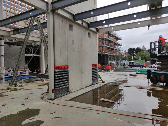
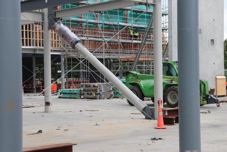
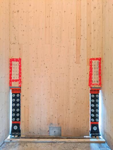
• Utilize self-centering technology such as resilient slip friction joints (RSFJs) by Tectonus that provide both damping and a restoring force to recenter a structure so that there is zero residual drift. RSFJs can be used in-line with any lateral force resisting element including braces and ends of shear walls (Figures 5-6). This system is extremely effective and has been tested to show that it essentially produces zero residual drift. In addition, since this system does not rely on material yielding, there will be no structural elements to repair following a major earthquake. Most likely, this enhancement will require a design peer review.
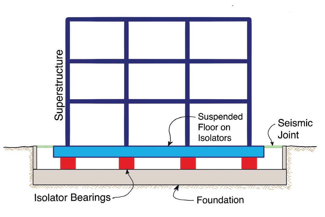
• Utilize base isolation system (Figure 7) that does not rely on steel yielding and inherently provides a restoring force that helps mitigate the effect of residual drift. This is an effective system to mitigate residual drift as well as minimize damage to the building. To implement base isolation, a significant construction cost increase will be incurred, and a design peer review will be required.
• Design a much stiffer and stronger lateral system that stays elastic
at higher force levels and does not rely on a high level of ductility. Doing this can have adverse effects by causing much higher lateral accelerations within the building, causing more damage to the building contents. In addition, a stiffer and stronger lateral system will require much more structural material and will be expensive. This can be effective for unusual structures with many irregularities but is not recommended for conventional structures.
In summary, minimizing residual drift in buildings following an earthquake is vital for maintaining functionality and the usability of buildings. It facilitates faster recovery, reduces repair costs, preserves structural elements, and enhances public confidence in the resilience of buildings. By striving for minimal residual drift, communities can mitigate the potential consequences of seismic events and build a safer and more resilient built environment. To achieve minimal residual drift engineers should inform their clients of the potential seismic residual drift that could occur with a standard code design based on ASCE 7 & ASCE 41 and then propose design enhancements that mitigate the amount of residual drift that could occur. To implement these enhancements, a performance-base-design approach utilizing a non-linear analysis may be needed which could require a design peer review. ■
Full references are included in the online version of the article at STRUCTUREmag.org
John Worley, S.E, retired Principal at Arup, has practiced Structural Engineering in California for over 35 years and has designed many significant structures including Apple Park in Cupertino, currently is the US Advisor for Tectonus (john.worley61@gmail.com)
Pierre Quenneville, Ph.D, Professor at University of Aukland, New Zealand, Founder & Chief Technical Officer of Tectonus. (pierre.quenneville@tectonus.com)

MARCH 2024 13
Figure 3. Moment frame with viscous dampers. Figure 4. Rocking shearwall system.
Figure 5. Self-centering resilient slip friction joints in concrete and CLT shearwalls.
Figure 7. Illustration of base isolated building.
Figure 6. Self-centering resilient slip friction joints in steel and timber braces.
structural DESIGN
Seismic Response Factor in Cold-Formed Steel Flat Strapped Lateral Systems
Two seismic designs are compared in a hypothetical 10-story building.
By Timothy R. Donahue, P.E.
Generally speaking, for a given structure, the higher the seismic response factor (R) value is, the more ductile the structure is and the lower the total seismic load acting on the building. With this concept in mind, one might conclude that reducing the seismic load acting on a building by selecting a more ductile seismic force restraint system (SFRS) with a higher R value would ultimately lower the material cost; however, when evaluating the overall cost implications for what it takes to achieve the increased ductility, the cost savings may not always be realized. This is primarily due to the requirements of overstrength factors in the design and detailing of the straps and other protected components of the SFRS with an R greater than 3.
For cold-formed steel framed buildings utilizing flat strap bracing in Seismic Design Categories (SDC) B or C, the structural engineer can design for either an R of 3 by clas sifying the SFRS as “Steel Systems Not Specifically Detailed For Seismic Resistance”, or for an R of 4 by classifying the SFRS as “Light-frame (cold-formed steel) wall systems using flat strap bracing” (per AISI Section A1.2.3 and Table 12.2-1 of ASCE 7-16). Due to increased ductility, buildings designed with an R of 4 have story forces that are 25% less compared to a building designed using an R of 3. To achieve the higher ductility however, more in depth design of the protected components is required in accordance with AISI-400, Section E3.2. These protected components include collectors, connections of strap brac ing, chord studs, vertical boundary elements, and floor to floor connections of the boundary elements (see figure 1). This is to ensure that the energy dissipating elements (the straps) yield while the boundary members and connections remain elastic.
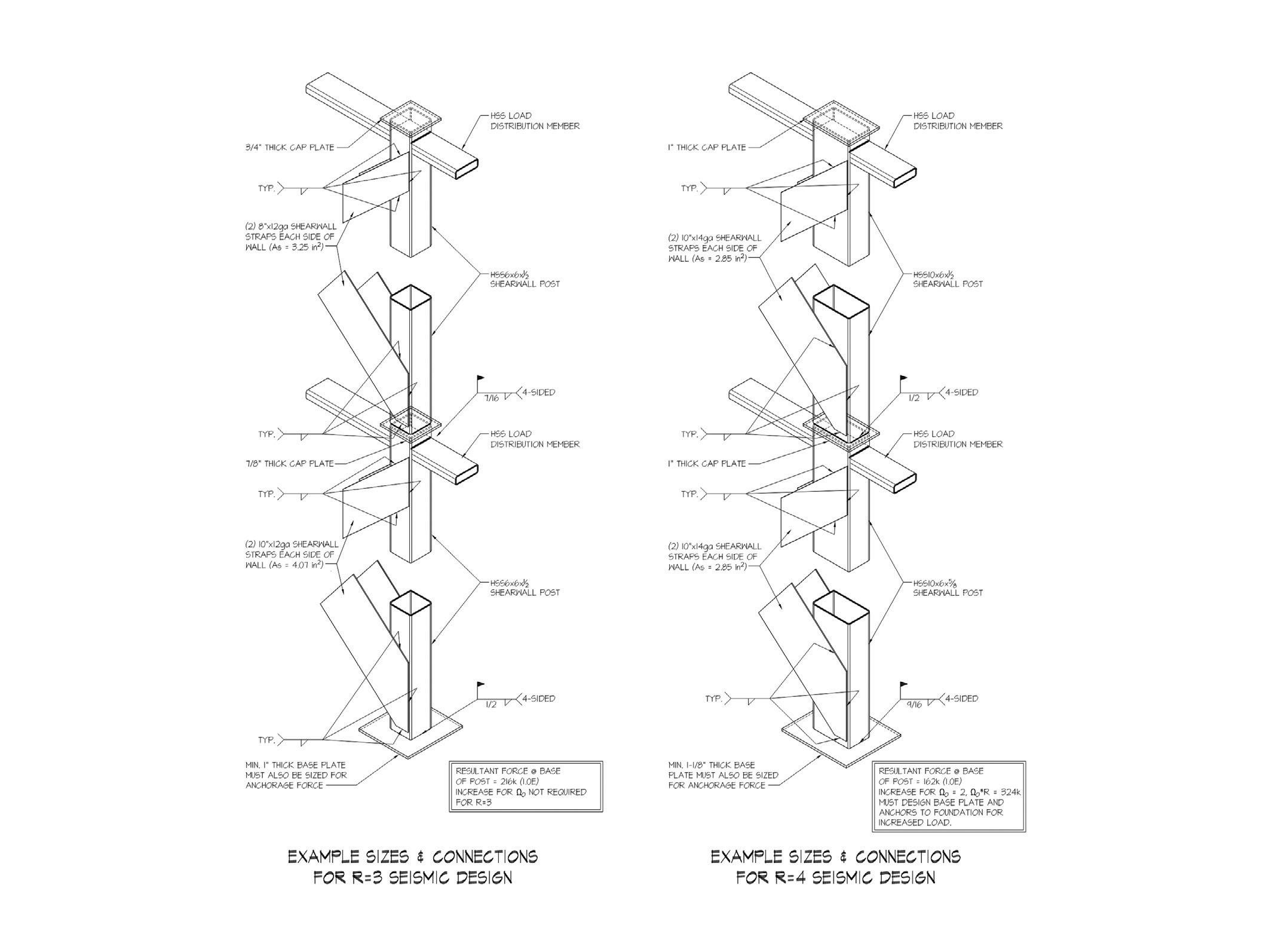
To better understand the potential cost implications of the two different designs, let’s look at a typical end post connection of a hypothetical ten story building, in SDC B, that uses a light gauge strapped wall bracing SFRS. Figure 1 shows the connection design for the R=3 case, while Figure 2 shows the connection design for R=4.
As expected, the strap sizes are slightly smaller (or lighter) for the design utilizing an R of 4, as the lower base shear values result in lower strap forces. However, the end post sizes are larger for the R=4 design in order to provide enough weld length for the end post tensile and shear forces. While there are other potential solutions to resolving the increased connection forces beyond increasing the post size, such as adding angles or gussets, each solution ultimately adds cost to the assembly which offsets or negates the savings found in the straps.
Another element of the SFRS that is impacted by the overstrength requirements is the anchorage of the assembly to the concrete foundation. For the aforementioned building, the embed plate with welded studs used to transfer the loads into the foundation would need to accommodate
324 kips of total load for the R=4 design once overstrength is applied but would only need to account for 215 kips in total for the R=3 design. The larger forces, once the overstrength factor is applied, for the R=4 condition results in a more expensive base connection.
In this specific test case, the lower base shear obtained by using the higher R factor did not correlate to a more economical structure. The more ductile design (with R = 4) is in fact quite a bit more costly than the simplified design (with R = 3) despite having to resist lower seismic loads. While this result will not always be the case and there often is potential to economize a building’s lateral design by taking advantage of the reduced story shears resulting from an R of 4, the cost impact of overstrength requirements needs to be considered when selecting the SFRS. ■
Timothy R. Donahue, P.E. is Project Manager at Mulhern + Kulp. He can be reached at tdonahue@mulhernkulp.com.
STRUCTURE magazine 14
Figure 1 (left). Connection design for the R=3 case. Figure 2 (right). Connection design for R=4.
RISA NEW RELEASE
PRODUCT RELEASES FOR 2024 NOW AVAILABLE

Trusted leader in 3D analysis and multi-material design.
VERSION 22.0 UPDATES
Tapered Member Area Load
Columns in Walls
Customizable Hot Keys
Move Nodes Graphically with Mouse


Model, Load, Analyze and Design Multi-Storybuildings with ease.
VERSION 18.0 UPDATES
Enhanced Wall Panel Opening
Quick Add & Edit Tool
Columns in Walls
COME VISIT US
NASCC: THE STEEL CONFERENCE BOOTH #911
Your One-Stop Shop for Foundation Design.
VERSION 16.0 UPDATES
Modernized Ribbon User Interface
Improved and Better Organized
Drawing Tools
Improved Graphics and Report
Printing
Fully Integrated Design for Concrete Buildings
VERSION 23.0 UPDATES
Torsion Design of One-Way
Slabs and Beams
New Tendon and Rebar Display
Managers
Column Code Check Improvements
RISA o ers a comprehensive suite of design software that work together to simplify even the most complex projects. As a result, engineers can work e ciently on a variety of structures in a mix of materials including steel, concrete, wood, masonry and aluminum. risa.com
structural DESIGN
Declaring Independence
Structural design considerations for independent equipment frames in existing buildings
By Kyle A. Karschner P.E., S.E., Jacob Sun, P.E., and Michael F. Hughes, P.E., S.E.
Building owners are turning to adaptive reuse of existing buildings to meet the market demand for alternative uses, such as life science, data, robotics, and other tech-related industries. These uses typically require upgrading the building’s mechanical, electrical, plumbing, and fire protection (MEP-FP) systems that use larger and heavier equipment than the building’s original structural design. As a result, this work can trigger costly structural upgrades for strength, serviceability, or both to comply with building code requirements.
When an alteration increases design gravity and lateral loads (wind or seismic) on structural elements beyond certain thresholds, the International Existing Building Code (IEBC) requires evaluating those elements. In general, if the demand-to-capacity ratio for gravity load resisting or lateral load resisting elements increases by more than 5% and 10%, respectively, the designer must show that those elements satisfy the gravity and wind load provisions of the International Building Code (IBC), and the reduced seismic provisions of the IEBC.
Many older and historic buildings do not have well-defined lateral load resisting systems (LLRS) or lack the gravity and/ or lateral capacity to accommodate the additional loads, which makes reinforcing the existing structure per IEBC requirements challenging and sometimes cost-prohibitive. To address this issue, the authors have designed new independent equipment frames within the existing building footprint to carry most, if not all, of the new equipment. This strategy can meet the project goals without whole building strengthening or a detached horizontal addition. Avoiding the latter might save the project from additional zoning reviews and approvals processes by the Authorities Having Jurisdiction (AHJs). This article discusses the design considerations for these independent frames.
Example Frame Types
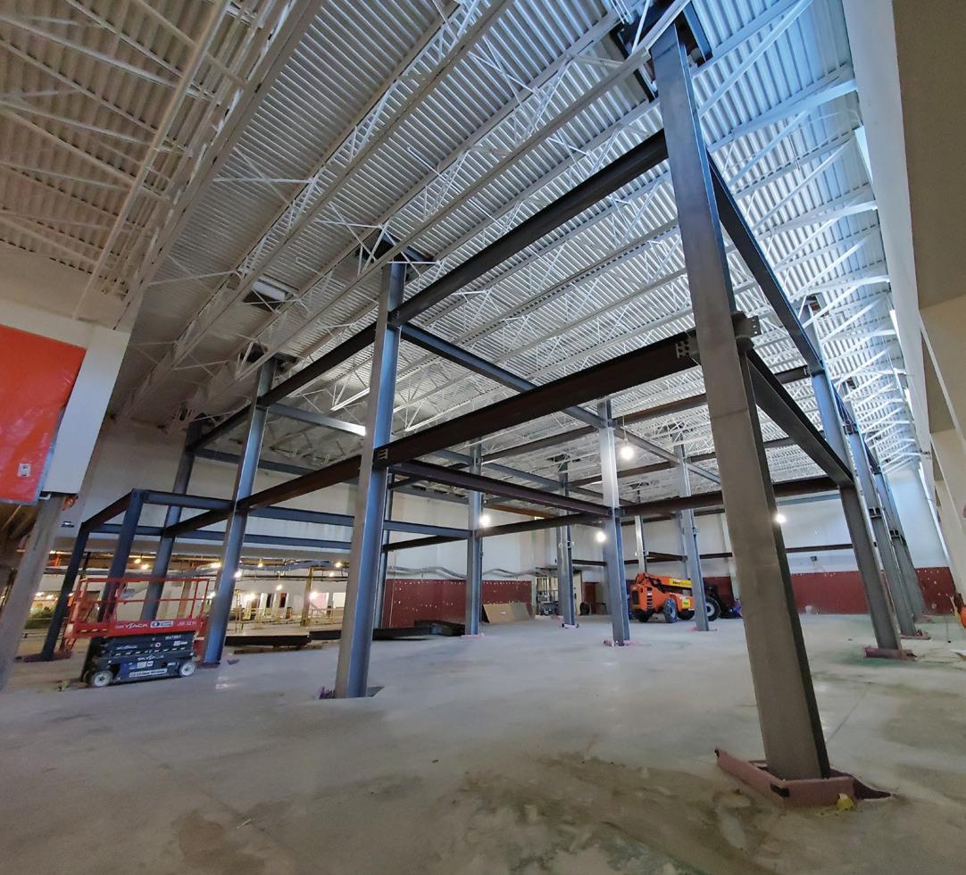
Several approaches exist to designing independent frames within existing buildings, depending on the building geometry, story height, overhead clearance, aesthetics, and other constraints. The authors have used the three types shown in Figure 1 for various design applications.
Type 1 is an interior mezzanine, the simplest version of a structurally independent frame. The columns typically go through any interior building floor(s) but do not penetrate the roof. Columns installed through floors require floor openings. A 3-foot by 3-foot opening is typically adequate for most columns and tolerances. After installing the columns, infill the openings with matching floor construction, but provide proper separation joints for fire separation between floors and relative movement between the original and new structure. Ideal candidates for this system type are tall warehouse structures with lightly framed roofs, buildings with shallow purlins with widely-spaced deep roof trusses allowing equipment and access between the trusses, or buildings requiring intermediate floor space for mechanical or other occupancy uses.
Type 2 can be used if the existing building has limited overhead clearance for a mezzanine or a lightly framed roof structure that cannot support the new equipment. In this system, the independent platform frame extends through the roof. Sometimes, designers add screens to conceal the rooftop equipment; however, the screens can add significant wind load to the building. The engineer and the architect must pay close attention to the details of columns penetrating the roof to provide adequate movement, maintain fire separation, prevent leakage, and minimize thermal bridging. The size of the roof openings is similar to the floor openings of Type 1. The Type 2 system typically works well with existing 1-2 story buildings. For taller buildings, the column sizes

STRUCTURE magazine 16
Figure. 1. Independent frame types are depicted.
can be large and uneconomical due to long unbraced lengths and lateral load stiffness demands, and larger columns increase the likelihood of interferences with intermediate existing structures and MEP-FP service lines at lower floors.
Type 3 is an independent exterior penthouse. This system is similar to Type 1, except exterior, and Type 2, except enclosed. The authors consider this system when the renovation requires additional indoor mechanical units, but there is insufficient interior space or height clearance.
Design Considerations
Common to All Types
Common design considerations exist for all independent equipment frame types described in the previous section.
Lateral Load Resting System (LLRS)
Like buildings, independent equipment frames require their own LLRS and close coordination with the project team and stakeholders to select the best system and layout. The authors have used braced frame and moment frame systems. The authors found that architects and owners typically opt for moment frames because they introduce less structure into the interior spaces where the owner or end-users are accustomed to only the existing structure. Although moment frames have less interior structure than braced frames, moment frames usually require deeper beams.
For seismic loads, the designer must determine whether the independent equipment frame is a “building structure,” “nonbuilding structure,” or “nonbuilding structure similar to a building,” as defined by ASCE 7, to select the appropriate design method. The authors believe that most independent frames should comply with the seismic design requirements for a “building structure” (ASCE 7-16 Ch. 12) so that the frame has performance and reliability similar to or exceeding those of the surrounding building.
For wind loads, the authors consider shielding provided by the surrounding building; therefore, the Type 1 system is not subject to wind loading. The Type 2 system is subject to the loads defined by ASCE 7-16, Chapter 29 (Building Appurtenances). Depending on the footprint of the Type 3 system, ASCE 7-16 Chapter 29 applies for penthouses with a small footprint relative to the building, or Chapter 27 or 28 (Building Structures) applies for penthouses with large footprints compared to the main building. The design wind pressures will be higher for penthouses with a small relative footprint.
The independent equipment frames often require intermediate beams below the floor and roof levels. These beams serve two primary purposes: 1) brace multi-story columns and 2) being part of the LLRS. These beams should be set sufficiently below the existing floor or roof structure to accommodate deflection and construction tolerances of the new and existing structures. The engineer must coordinate these beams with the project team because they reduce overhead clearance and may clash with existing or proposed MEP-FP service lines.
Column Layout and Foundations
Locating new columns and footings within the existing structure is a multivariable challenge. The column layout must avoid existing roof and floor framing and provide sufficient clearance for the relative movement of the two structures and construction tolerances.
Foundation exploration via selective demolition or test pits should be performed early in design to locate and understand all below-grade
elements. For the equipment frame foundations, designers should consider proximity to existing foundations and other below-grade obstructions, like under-slab utilities.
Separation joints between existing and new foundations are unnecessary since the relative horizontal movements at the foundation level are generally negligible. However, where the new and existing foundations abut, provide a bond breaker between the foundations to reduce unintended gravity load transfer.
Designers should avoid retrofitting the existing foundation for the new frame column with large gravity loads to create a combined foundation because there could be differential settlement when loading the new column.
For buildings supported on shallow foundations, the authors consult with the geotechnical engineer and typically design the new foundations for an allowable bearing pressure less than the original design bearing pressure to reduce the risk of excessive differential settlement.
The equipment frames require new piles and pile caps for buildings supported on deep foundations. Drilled-in piles are typically used to control vibration and noise transmission. The existing structural slab must be locally removed and replaced for the new deep foundation installation. The slab replacement must be isolated from the new columns.
Installing new foundations in buildings where the base slab resists sustained hydrostatic uplift pressures (i.e., pressure slabs) is likely technically infeasible or not economically practical.
It is usually preferable to place the new frame columns as close to the existing building columns and exterior walls as possible to maximize program flexibility. These schemes often result in foundations with eccentric loadings. The authors regularly use strap beams to resist eccentric foundation loads.
Separation Joints
The interfaces between the new frame and the existing structure require separation joints to isolate the new frame properly. Figure 2 shows a Type 2 structure with columns penetrating the existing roof deck with separation joints. The joints must accommodate the relative lateral movement between the new and existing structures (i.e., the two structures moving towards or away from each other) and incorporate
MARCH 2024 17
Figure 2. Type 2 frame columns are shown isolated through the roof deck
fire protection requirements.
To estimate the existing building’s horizontal movement, designers commonly use the IBC and ASCE 7 maximum drift limits to estimate the wind and seismic movements of the existing building instead of analyzing the entire building.
The structural engineer must provide the selected joint size to the architect and other project team members. Designers must detail the architectural and MEP-FP elements that cross the joints to accommodate the relative movement. The design team must clearly indicate these requirements in the contract documents. During construction, the structural engineer should inspect the as-built separation joint to ensure the new and existing structures are not inadvertently tied together.
Fire Protection
Fire protection requirements can impact the structural and separation joint detailing and must be coordinated with the project’s architect and code consultant.
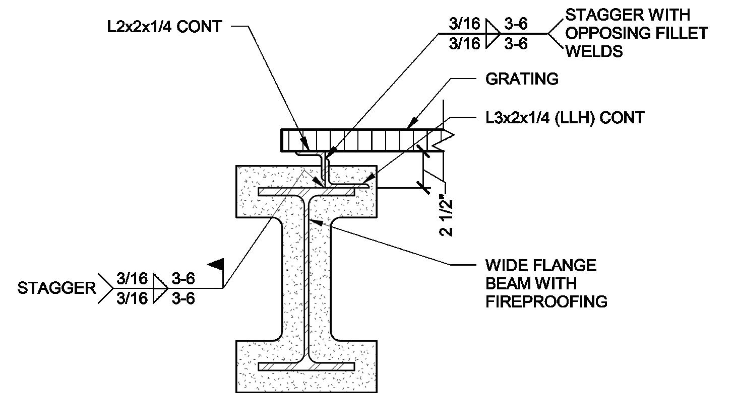
In one instance, there was a need for continuous fireproofing around beams that support grating for equipment access. The grating would have conflicted with the fireproofing. The authors raised the grating above the fireproofing using continuous angle bolsters like those in Figure 3 to allow for continuous fireproofing.
The architectural or code drawings should clearly delineate the extent of fire protection to avoid unnecessary fireproofing. Depending on the project, the new frame may not require fire protection compared to the adjacent existing construction.
Type 2 and 3 Specific Design Considerations
Type 2 structures have interior and exterior structural elements. Since the columns pass through the roofing, they can create a thermal bridge. Designers can provide a thermal break at the roof’s insulation plane, consisting of a thermal isolation pad, module, or coating. The architect, envelope consultant, and mechanical engineer should review the impacts of this bridge and determine whether they should provide a thermal break.
Where the frames are located in buildings with considerable floorto-floor heights, such as warehouses, it is possible to infill with intermediate framing, similar to the Type 1 system, to create an interior mezzanine space. Depending on the project, the owner may want flexibility to add the infill floors in the future; therefore, designers should discuss the current and future conditions with project stakeholders to determine design requirements.
A significant design consideration for Type 3 structures is the penthouse height. Avoid setting the penthouse floor at or below the roof elevation to improve waterproofing and reduce leakage potential. To minimize the penthouse height, the designers can set the floor slightly above the adjacent roof elevation, approximately 6 inches. If a higher penthouse elevation is acceptable, the designers can locate the mechanical level above the existing roof, creating an interstitial space. In that case, most of the roof structure can remain, except for small roof openings to install the columns like Type 2.
Depending on the project, the interstitial space may present some challenges if it requires conditioning, fireproofing, and accessibility for maintenance.
Since the Type 3 system may create a large opening in the roof diaphragm, the diaphragm stresses near the opening can be significant and may require local diaphragm strengthening. Also, the penthouse may change the wind uplift zones on the existing roof; therefore, the engineer should check the deck fasteners for combined in-plane shear and uplift loading.
Snow drifts could accumulate next to the new frame depending on the proximity of the Type 2 and 3 systems to the roofing. Starting with ASCE 7-16, Section 7.8 specifies that drift loads may be ignored when the bottom of the platform or other projection is at least 2 feet above the balanced snow load height. The engineer must evaluate the existing structure, including the roof deck, beams, columns, and their connections, to confirm adequacy for any added snow loads. In addition to snow drifts, designers should consider potential reroofing when establishing the clear height under the platform in a Type 2 structure. The National Roofing Contractors Association (NRCA) Roofing Manual for Membrane Roof Systems contains recommendations for clearances under the platform to allow for roofing.
Conclusion
For projects that add significant gravity and lateral loads to existing buildings, new independent frames within an existing building can reduce the impacts on the existing building’s structure. A successful design of these independent frames relies on proper detailing and close coordination with the project team during design and construction. ■
Kyle A. Karschner, P.E., S.E., is a Senior Consulting Engineer at Simpson Gumpertz & Heger’s office located in Waltham, MA (kakarschner@sgh.com)
Jacob Sun, P.E., is a Consulting Engineer at Simpson Gumpertz & Heger’s office located in Waltham, MA (jsun@sgh.com)
Michael F. Hughes, P.E., S.E., is an Associate Principal at Simpson Gumpertz & Heger’s office located in Waltham, MA (mfhughes@sgh.com)
STRUCTURE magazine 18
Figure 3. Bolster for grating support above fireproofing




LOCATIONS
St. Louis: 866.421.2460
Great Lakes: 314.568.3827
N. Central: 612.280.8940
Northeast: 410.568.5261


structural DESIGN
Watch Out for Unevenly Loaded Welds Part 2
Welds with nonuniform loading require special design attention.
By Duane K. Miller
Many welds are evenly loaded: the applied loads are uniformly transferred through the throat and length of the welds. Such welds are easily designed and routinely perform as expected. Other welds, however, are unevenly loaded. One end of the length of the weld may be more severely loaded than the other, or the loading along the weld throat may be non-uniform. The design of these welded connections is more complicated.
Fortunately, design codes dealing with welded connections, such as the American Institute of Steel Construction’s AISC 360, Specification for Structural Steel Buildings, and the American Welding Society’s AWS D1.1, Structural Welding – Steel provide design rules to accommodate unevenly loaded welds. The unfortunate situation is that engineers and detailers involved with the design of welded connections may be unaware of the need to treat such connections in a special manner. When unevenly loaded welds are treated incorrectly, the performance of the welded connection will likely be compromised.
This article summarizes five of the ten most frequently encountered conditions involving unevenly loaded welds. See Part 1 of this article from the February issue of STRUCTURE for Conditions 1 through 5.
Condition 6: Unevenly Loaded Because the Weld Group is Unevenly Loaded
In many situations, a weld group resists the applied loads. A beamto-column connection, for example, may consist of groove welds to the flanges and fillet welds to the web. In this case, the weld group consists of horizontal groove welds and vertical fillet welds. Collectively, this weld group resists the moment and shear applied to the connection. However, the various components of the weld group are not evenly loaded. Bending loads the top flange weld in tension and the bottom flange weld in compression. The vertical fillet welds to the beam web resist tension at the top and compression at the bottom, resulting in an unevenly loaded weld group. There are several ways to deal with unloaded weld groups. One of the easiest ways is to use the AISC Steel Manual approach, as shown in Tables 8-4 through 8-11. The Steel Manual discusses how to use the tables, as well as alternative methods to the tabular approach,

such as the instantaneous center of rotation method.
Condition 7: Unevenly Loaded Because the Weld Attaches a Rigid Member to a Flexible Member
The late Omer W. Blodgett, a pioneer in the design of welded connections and the author’s mentor, famously said, “One of the common oversights is failure to provide a path so a transverse force can enter that part of the member (section) that lies parallel to the force.” A parallel member is stiff, and forces preferentially are attracted to the stiff part. Accordingly, Blodgett encouraged designers and detailers to “provide a path” so the force could be transferred to the stiffer member.
When such a path is not provided, the welded connection is unevenly loaded; more load is transferred through the weld that is connected to the stiffer portion of the member or section, and correspondingly, less is transferred through the weld connected to the flexible part.
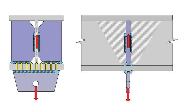
As shown in Figure 1, Part A contains an example where the lug is parallel to the beam web. In this case, the transfer of load through the weld is direct and uniform. In Part B, the same lug is welded to the same beam, but the lug is rotated 90 degrees. The loading is no longer uniform as the flange is flexible. Part C provides a possible solution: stiffeners have been added in order to “provide a path” for the force to enter into the parallel member, i.e., into the web.
Condition 8: Unevenly Loaded Because Transverse Welds are Combined with Longitudinal Welds
Some welded connections involve combinations of longitudinal and transverse welds, as shown in Figure 2. Testing has demonstrated that transverse welds are stronger than longitudinal welds. AISC 360 equation J2-5 addresses this directional strength increase. Transverse fillet welds are generally permitted to be loaded to a 50% higher level than longitudinal fillet welds of the same size and length, made with the

STRUCTURE magazine 20
A B C
Figure 1. Even and uneven welded connections, adapted from Blodgett.
Flush frame

Design composite joist end connections more quickly and efficiently
Improved flush-frame connections by New Millennium feature a more efficient design that eliminates beam torsion concerns. Our new standardized connections simplify design and specification. Now you can more quickly realize the added benefits of flush-frame connections in multi-story applications. Together, let’s build it better.

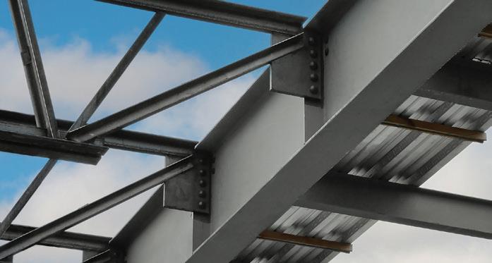
LEARN MORE
Standardized connections reduce design time Joist reaction point occurs at beam centerline
Flush-frame connection designed for efficiency
SEE US AT NASCC BOOTH 1117 newmill.com


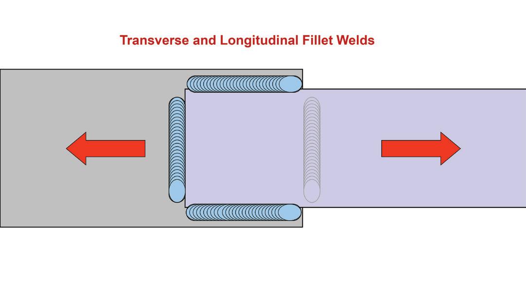
same filler metal. The directional strength increase factor (kds) is 1.0 for longitudinal fillets and 1.5 for transverse fillets.
The unevenly loaded condition occurs when transverse and longitudinal welds are combined in one connection. Because of the differential deformation capacity, the transverse weld will assume more load than the longitudinal weld. Therefore, it is not acceptable to directly add the capacity of the longitudinal weld with kds = 1.0 and transverse fillet weld with kds = 1.5. Instead, two conditions should be considered when this unevenly loaded condition exists. First, the capacity of the transverse weld and the longitudinal weld are directly added, assuming kds = 1.0 for both welds (i.e., with no directional increase for the transverse weld). Then, the capacity of the two welds is evaluated using this relationship as shown in equation J2.6 in AISC 360:
R n = 0.85 F nwAwel + 1.5F nw A wet where
Awel = effective area of longitudinally loaded fillet welds, in.2 (mm2)
A wet = effective area of transversely loaded fillet welds, in.2 (mm2)
The capacity of the two welds may be taken as the greater of the two calculations. Depending on the relative capacity of the two different weld orientations, either the normal strength calculation (i.e., with kds = 1.0 for both welds) or the strength calculated in accordance with equation J2.6 may provide the greater capacity.
Condition 9: Unevenly Loaded Because the Weld is Part of a Tubular Connection
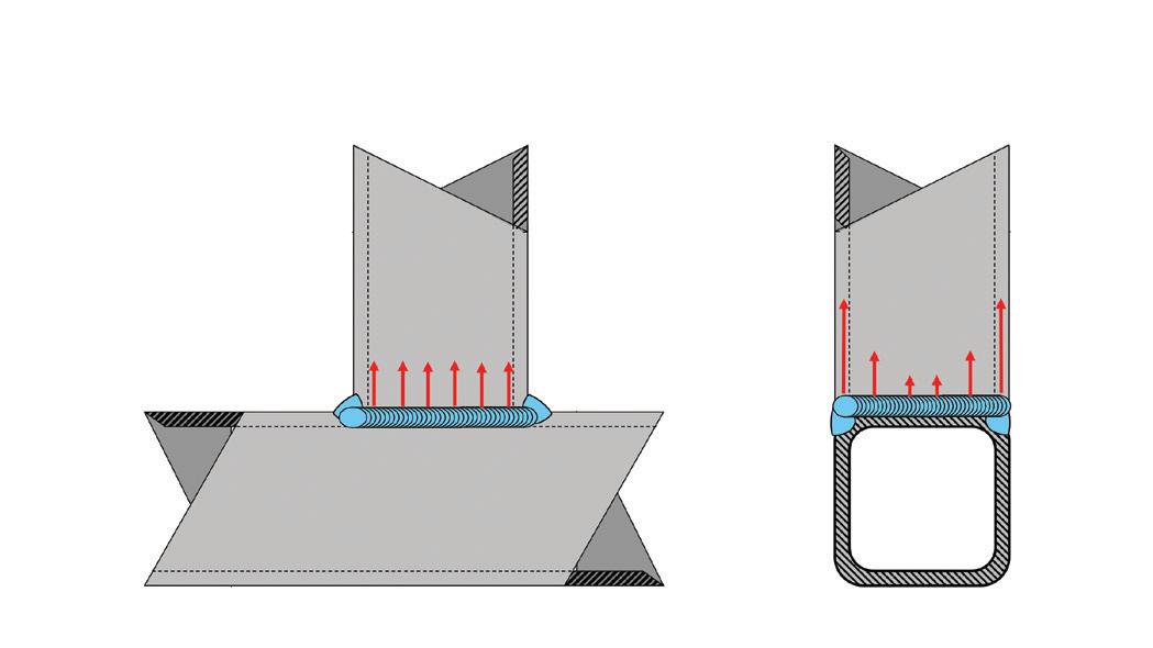
When tube-to-tube connections are made, the welds around the tube may be unevenly loaded due to the variable stiffness of the tube. Condition 9 is a specialized example that is related to the previously discussed Condition 7. Consider a square-tube to square-tube connection in a tee configuration, as shown in Figure 3, where the tubes are of the same size. The flare groove weld (i.e., the longitudinal weld) that connects the branch tube to the main tube is evenly loaded along its length. The side wall of the main member is stiff. The fillet weld across the face of the main member (i.e., the transverse weld) is unevenly loaded since the face of the tube is flexible. This flexibility forces an additional load to be transferred into the longitudinal weld.
AISC 360 provides “effective length” factors that account for this uneven loading.
Returning to the longitudinal flare groove weld, it was previously stated that the weld was uniformly loaded along its length. However, due to the flexibility of the tube face, the longitudinal weld is not uniformly loaded along its throat; strains are concentrated at the weld root when the tube face deflects. Therefore, the directional strength increases (discussed under Condition 8) cannot be applied to welds on the ends of square HSS members. This is a new restriction incorporated into the 2022 edition of AISC 360.
Condition 10: Unevenly Loaded Because Welds are Combined with Bolts or Rivets
The final condition examined is when welds and mechanical fasteners are expected to share loads in a single connection. This is not a typical situation for new construction where it is common to use welded or bolted connections, but not both in a single connection. The typical application of this condition involves the retrofit of existing mechanically joined connections where welds are specified to add new capacity. Occasionally, for new construction, changes made to the structure late in the construction process may necessitate the addition of welds to bolted connections for additional capacity for conditions that were unexpected during the original design process.
Condition 10 deals with uneven loading between the welds and mechanical fasteners, not uneven loading on the weld itself. As was discussed in Condition 8, transverse welds are stiffer than longitudinal welds. Welds, regardless of their orientation, are stiffer than bolted connections. Thus, the relative deformation capacity of all the elements in a single connection needs to be considered when the strength of the connection is determined. There are several factors that must be considered: longitudinal versus transverse welds, the type of bolted connection (e.g., snug-tight versus pretensioned), whether rivets or bolts are involved, and whether slip has likely occurred in the bolted connection.
AISC 360 states: “Bolts shall not be considered as sharing the load in combination with welds, except in the design of shear connections on a common faying surface where strain compatibility between the bolts and welds is considered.” After the prohibition on sharing loads between bolts and welds, an exception is listed: sharing of loads is permitted when strain compatibility between bolts and welds is considered. AISC 360 provides details of how longitudinal welds and pretensioned high-strength bolts can be considered to share load.
Conclusion
There may be, and probably are, situations where welds are unevenly loaded other than the ten commonly encountered conditions discussed in Parts 1 and 2 of this article. Engineers should watch out for uneven loading on welds and take action to mitigate it. More detailed information on how to mitigate these conditions can be found in AISC 360, the AISC Steel Construction Manual, and AWS D1.1. ■
Full references are included in the online version of the article at STRUCTUREmag.org .
Duane K. Miller, PE, ScD, is a recognized authority on the design and performance of welded connections. He retired after 44 years of service with The Lincoln Electric Company who retains his services as a consultant.
MARCH 2024 21
Figure 2. Transverse and longitudinal fillet welds in a single connection.
Figure 3. Uneven loading on a square HSS tube-to-tube tee connection
structural ANALYSIS
Special Wind Zones in Washington and Oregon
Site-specific wind studies have indicated special wind regions on the east side of the Cascades in Oregon and along the Columbia River Gorge could be eliminated.
By Seth Thomas
Special Wind Regions (SWR) are defined in ASCE 7-22 Section 26.5.2.
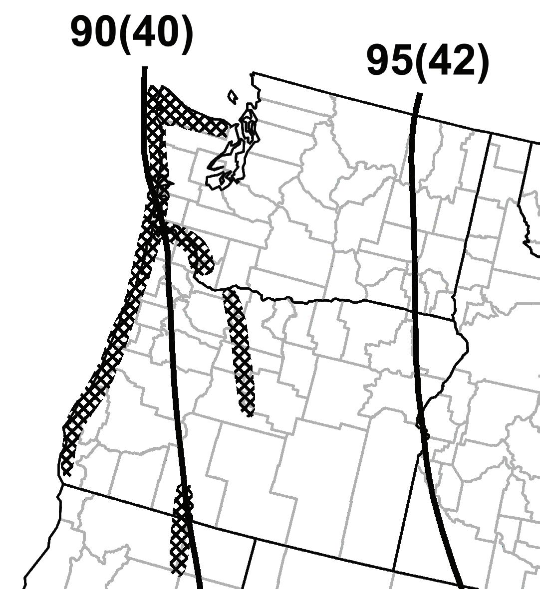
as “Mountainous terrain, gorges, and special wind regions shown in Figure 26.5-1.” These regions are identified in ASCE 7 to highlight the lack of data or the high variability of wind speeds in localized areas where the wind data from the surrounding areas may not be adequate to properly capture the hazard.
The origin of special wind regions by name is from ANSI A58.1-1982 (predecessor to ASCE 7-88). The initial special wind regions were established without detailed analysis but were based on the expertise of climate/ wind experts on the ANSI A58.1-1982 committee. While the extents and locations of these regions have changed somewhat, they are very similar in ASCE 7-22 to what they were in ANSI A58.1-1982.
Before ANSI A58.1-1982, the 1978 Oregon Structural Specialty Code (OSSC) specified higher wind speeds along the Oregon coast and the Columbia River Gorge, the 80-mile-long portion of the Columbia River east of Portland. It should be noted that the special wind region in the OSSC along the Columbia River Gorge never existed in ASCE 7 or the building codes on the Washington side of the river.
The commentary in ASCE 7-22 notes that the lack of climatic data along
the Washington/Oregon coast as the reason for that special wind region. The Commentary further states that winds blowing over mountain ranges or through gorges or river valleys have the potential to develop speeds that are substantially higher than the maps of ASCE 7 Figure 26.5-1.
ASCE 7 Section 26.5.2 and the ASCE 7 Commentary note that the design wind speed for the special wind regions specified in ASCE 7 are to be determined by the Authority Having Jurisdiction (AHJ), based on regional knowledge and experience. In Oregon, design wind speeds are established by the state Building Codes Division and have remained static for several code cycles (same for 2007/2010/2014/2019, except for the conversion to strength level in 2014). In Washington, basic wind speeds are determined by each of the nine county AHJs with SWRs. After the significant reduction in wind speeds in ASCE 7-16 (adopted in the 2019 OSSC) wind speeds in the special wind regions for Oregon and Washington typically became 25 to 35 mph higher than those in the adjacent nonspecial wind region areas. This results in wind pressures that can be 50 to 90% higher. This difference comes before any exposure and topographic factors have been applied. Some of the edges of the special wind regions do occur in populated areas, thus a large step function can occur leading to significant changes in design loads at the border of these zones.
Footnote 6 of ASCE 7 Figure 26.5-1A states that site-specific values for selected special wind regions noted on the maps shall be permitted to be determined using the ASCE Wind Design Geodatabase in the ASCE Hazard tool https://asce7hazardtool.online. Site specific analyses have been performed in accordance with ASCE 7 Section 26.5.3 for northern Colorado and Kern County, California, with the results adopted in ASCE 7-22 and incorporated in the Hazard tool.
In 2018, as part of the 2019 OSSC adoption process, the Structural Engineers of Oregon (SEAO) Code Committee submitted a code change proposal to the State for the adoption of ASCE 7-16, which included the recommendation that a site-specific study be performed for the Oregon

STRUCTURE magazine 22
Excerpt from ASCE 7-22 Figure 26.5-1A. Special Wind Regions (SWR) are defined in ASCE 7-22 Section 26.5.2. as “Mountainous terrain, gorges, and special wind regions" shown here. Figure 1609.3 from 2022 OSSC: Special wind regions in Oregon are noted.
BUILD TALL WITH POWER COLUMN ®

STRONG, EFFICIENT, SUSTAINABLE
POWER COLUMN® FEATURES
• Complement to Mass Timber wood framing systems
• Sustainable Forestry Initiative (SFI®) Certified
• Manufactured with superior strength southern yellow pine MSR Lumber
• Available in range of appearance grades for structural and architectural applications
• Superior alternative for Tall Wall applications
• Load path solution for Engineered Beam and Header Products
• Framing members such as Power Beam® can easily be attached to Power Column® with simple connection detailing


©Anthony Forest Products Company, LLC WWW.CANFOR.COM | 800.221.BEAM | WWW.ANTHONYFOREST.COM Anthony Forest Products is part of the Canfor Group of Companies


special wind regions as part of the change proposal. While Oregon agreed it was a worthwhile effort, there was no funding available, so this was dropped as part of the 2019 OSSC adoption process. SEAO’s code committee reached out to the SEA Wind committee to establish a partnership with SEAW, and a budget was established based on the estimate to complete the work in both states. This partnership was prudent from a funding standpoint, as study costs along the Columbia River, the border between Washington and Oregon, could be shared by both SEAW and SEAO. Each SEA set out to fundraise their portion of the study with the intent to finish in time for adoption in the ASCE 7-22 cycle. This goal was not met and revised to target the ASCE 7-28 cycle.
In 2022, SEAW was able to complete funding and commissioned a site-specific study for all the SWRs in Washington State, including both the Washington and Oregon sides of the Columbia River. Funding was achieved with an NCSEA grant, significant contributions from the Structural Engineers Foundation of Washington, and numerous engineering consultants and individuals. The SWR study for Washington State and the Columbia River was completed in the summer of 2022.
In the summer of 2023, SEAO finished the process of raising money, commissioning, and completing the study for the remaining SWRs in Oregon. The special wind region studies for both Washington and Oregon (performed by CPP Wind Engineering Consultants) looked at climatic data from a number of local reporting stations near existing special wind regions (typically from regional airports) and used the same methodology to establish the design wind speeds based on Risk Category as established in ASCE 7-16. Using this process, the design wind speeds were established statistically and compared to the wind speeds shown in ASCE 7 outside the special wind region.
As a result of these two studies, there are significant reductions or eliminations of the special wind regions across both states. The studies showed that the special wind regions on the east side of the Cascades in Oregon and along the Columbia River Gorge could be eliminated. The extents of the special wind regions along the north coast of the Olympic peninsula and from the mouth of the Columbia River were significantly reduced. Additionally, while the special wind region on the Pacific Coast remained, the wind speeds established by the local AHJs along the Washington and Oregon coast could be reduced. The study did show one area where the existing special wind regions did not extend far enough. In the Southwest corner of Oregon in Curry County, the study showed the special wind region should extend to the Oregon/California border (and beyond).
After a review period by SEAO, Oregon’s study was finalized. The information from both studies is currently being used by SEAW and SEAO to pursue a change proposal for ASCE 7-28 to eliminate the unnecessary SWR, while mapping the wind speeds and updating the extents of the SWR that remain.
Since ASCE 7-28 will not be adopted until the 2030 IBC (2031 OSSC), the SEAO Code Committee has been working with the Oregon Building Codes Division to allow for a path of early adoption of these reduced wind speeds. On August 9th, 2023, the Oregon Building Codes Structures Board approved an interim amendment to the 2022 OSSC for the reduction in wind speeds the special wind regions shown in ASCE 7-16 matching the results of the study. The interim amendment went into effect on October 1st, 2023 (https://www.oregon.gov/bcd/codes-stand/Documents/22osscdesignwindspeed-amendments.pdf). The special wind regions in the Columbia River Gorge, Redmond/Bend area and Klamath falls area are all essentially eliminated by defaulting the special wind region speeds in these areas to match the adjacent area per ASCE 7-16. The special wind region at the coast will remain but most counties will see a reduction in wind speed. SEAW has authored a white paper, approved by SEAW’s State Board of Directors, and published in February 2023, recommending a similar reduction matching their study (https://static1.squarespace. com/static/5c3faa364eddecdc367bedc5/t/63f3db7af61577050df48 30e/1676925822712/White+Paper+WEC+%233+-2023.pdf). These recommendations are being submitted by SEAW for consideration as a 2024 amendment to the Washington State Building Code.
In summary, the partnership of two-member organization to spearhead a study has led to improvements in design wind maps which will benefit the structural engineering profession. The changes would not have been possible without the outstanding efforts of the SEAO and SEAW committees, along with the generous donations by many to support their studies. SEAOC, and possibly SEAC will be joining SEAO and SEAW in submitting the results of their respective SWR site-specific study recommendations for adoption in ASCE 7-28. Much of this cooperation between these SEA Member Organizations was facilitated the NCSEA Code Advisory Wind Engineering Subcommittee. ■
Seth Thomas is an Associate at KPFF in Portland Oregon and a member of ASCE 7 Main, Flood, Tsunami, and Seismic, standard subcommittees. He can be reached at seth.thomas@kpff.com.
STRUCTURE magazine 24
Left: Recommended special wind regions in Washington (SEAW White paper). Above: Changes to wind speeds in 2022 OSSC based on October 1, 2023 interim amendment (Risk Category II)
STRONG. SECURE.

If seismic or high-wind challenges are important considerations for your next project, Vulcraft and Verco’s steel roof deck and PunchLok II® System is a valuable option to consider. Working with our team of experts early in your design process can help you evaluate the variety of value-added solutions that Vulcraft and Verco offer to ensure that you have the right system in place.
Contact an expert today.
 VULCRAFT VERCO
PUNCHLO K® II SYSTEM P NEUMATICALLY-OP ERATEDCONNECTO R
Seismic Rehab of the Oregon State Capitol

STRUCTURE magazine 26
The Oregon State Capitol Renovation project seismically retrofits and renovates multiple structures utilizing ASCE 41.
By John McDonald, S.E., Stefanie Chamorro, P.E., and Geoff Bomba, S.E.

Driven by the importance of the Oregon State Capitol and disproportionate seismic damage from the 1993 Scotts Mills seismic event, the Oregon Legislature moved forward with measures to protect and preserve the historic building. The project includes a seismically base-isolated retrofit of the 1938 Capitol building, which is a non-ductile brick infilled concrete frame structure with marble cladding. The Capitol is flanked by a pair of five-story 1977 reinforced concrete buildings retrofitted using a fiberreinforced polymer (FRP) strengthening system, which remain fixed base structures. The seismic isolation system of the Capitol utilizes a triple friction pendulum system tuned to reduce the acceleration of the building during a Cascadia Subduction Zone (CSZ) seismic event. Once complete, a new occupied level will be constructed below the existing building footprint to increase program space and meet the changing needs of the Oregon State Capitol.
History, Seismology, & Existing Buildings
The Oregon Capitol Building has been rebuilt three times in Salem, Oregon. The first two capitol buildings were destroyed by fires in 1855 and 1935, and the citizens of Oregon have a keen interest in preserving this third building, completed in 1938 with an adjacent expansion in 1977 to expand the Capitol complex (Figure 1). The State of Oregon performed multiple studies over the past decades to determine the optimal remedy to the seismic vulnerability of the Oregon State Capitol complex. A Master Plan, completed in 2009, recommended seismic rehabilitation, life-safety improvements, and renovations to improve the operational efficiency of the Legislature. The Capitol Master Plan Review Committee recommended that the seismic and other life-safety concerns be addressed as top priorities. Initial discussions focused on traditional methods such as adding concrete shear walls or applying fiber reinforced polymers to existing concrete walls. With the desire to preserve historic murals
Design Team
• Architects: SRG + CannonDesign and Architectural Resources Group
• Structural Engineers: Forell Elsesser Engineers and Catena Consulting Engineers
• General Contractor: Hoffman Construction Company
• Site Hazard Analysis Engineers: Geotechnical Resources, Inc. (GRI)


MARCH 2024 27
Fig. 1: (Left) An aerial photo of project site looking from the north (Photo Courtesy of SRG+CannonDesign). (Right) Plan view map of project site showing the interconnected building segments.
and fabric within the Capitol, the Design Team investigated a less structurally intrusive approach. The Review Committee prioritized seismic isolation as the preferred retrofit strategy and recommended that the 1938 portion of the Capitol be seismically isolated together with portions of the 1977 Capitol Connector building. There are distinct stakeholders who have influence and control of the project. The ownership decision authorities for the capitol complex is … complex: The Legislature owns and manages the buildings, while the Parks Services owns and manages the grounds. Finally, the Department of Administrative Services maintains responsibility and control for all utilities, monuments, and dedications. These entities, of course, are separate from the permitting authority.
Seismology & Ground Motions
There is significant geologic evidence indicating a tectonic plate boundary off the Western US coast—extending from northern California to Canada. The project site is approximately 40 miles from the eastern edge of the Cascadia Subduction Zone (CSZ) which is the active convergent plate boundary between the subducting Explorer, Juan de Fuca, and Gorda Plates and the overriding North American Plate. According to the Oregon Resiliency Plan, there is a 10-37% chance of occurrence of a Magnitude 8.0 or larger earthquake in the next 50 years. Based on the tectonic setting and historical seismicity, the Oregon State Capitol project site is subject to earthquakes from major sources such as megathrust earthquakes along the interpolate CSZ, interslab earthquakes on the subducted portion of the CSZ, and shallow crustal faults.
While there is a limited database of historical earthquakes for Oregon, two events have occurred within 50 miles of the site, including a

magnitude 4.6 in 1963 and a magnitude 5.6 event in Scotts Mills in 1993. The 1993 Scotts Mills earthquake caused damage to the Capitol, which prompted the initial phases of retrofitting the 1938 structure. This initial phase of seismic renovation strengthened areas with new concrete shear walls. These walls were strategically placed so as not to disrupt the historic murals and finishes within. While helpful, the available areas were limited. Additionally, these initial steps relied upon future completion—the new shear walls did not extend down to the foundation.
Given the significant variability in magnitude and types of earthquakes that could impact the site, GRI, the geotechnical consultant, completed a site-specific seismic hazard analysis for the project that included site response modeling from the underlying bedrock through the soil layers of interest. For the structural time history modeling, both amplitude scaling and spectral matching were initially considered while spectral matching was selected for final design of the seismically isolated portions of the retrofit following ASCE 41. To accommodate the range of potential earthquake sources and magnitudes, the number of time histories for each type of earthquake were selected based on review of the deaggregation, overall contribution at each hazard level, and period range of interest for the proposed base isolated solution. All the selected ground motions for non-linear response history analyses were subduction zone motions and deemed appropriate given the seismicity of the site.
Existing Buildings: 1938 Capitol Building
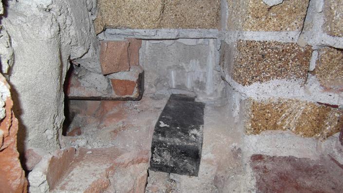
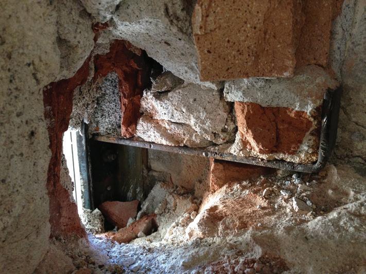
The 1938 main Capitol building is a four-story structure plus a basement with a central drum and rotunda and Senate and House chambers symmetrically placed to the east and west of the rotunda. The structure consists of a cast-in-place reinforced concrete frame with clay brick infill and some limited areas of unreinforced masonry (URM) bearing wall. Floors consist of reinforced concrete pan joist slabs spanning to concrete beams supported by concrete columns. The central drum has a cylindrical shape with a concrete roof slab spanning to steel beams supported on a circular URM bearing wall. This bearing wall is supported by a ring of concrete beams at the main roof level transferring the load to concrete columns that continue down the building. All concrete columns are supported on shallow footings that are constructed with a concrete plinth on a larger concrete base. At the exterior, the structure is clad with marble panels varying from 10 in. thick at the base and narrowing to a mere 6 in. at the

STRUCTURE magazine 28
Fig 2. Historic Drawings of Floor & Turret Plans.
Figure 3. This vintage out-of-plane anchor was deemed insufficient for modern loading.

upper levels. This cladding contributes to the already considerable weight of the building. The marble panels stack vertically from the base and are braced to the building with metal anchors into URM infill installed within the perimeter framing (Figure 3). At the drum, the marble is anchored to the URM bearing wall.
After the 1993 Scotts Mills earthquake, the rotunda of the building was strengthened with reinforced concrete shear walls. This retrofit was designed to a force level that assumed a subsequent project would seismically isolate the entire 1938 building. The entire dome and turret received an added layer of reinforced concrete shear wall cast on the interior. Below the transfer beams of the drum at the roof, a square layout of shear walls was constructed down to the foundation level.
Existing Buildings: 1977 Legislative Wings & Connector Building
The east and west Legislative Wing building structures are mirror images of each other and flank each end of the Connector Building. The Legislative Wings are separated from the Connector Building by an existing seismic joint. All three buildings consist of conventionally reinforced concrete pan-joist construction at the roof and floor slabs supported by reinforced concrete columns founded atop shallow spread footings.


Reinforced concrete shear walls founded atop shallow strip footings provide lateral resistance against wind and seismic forces. Exposed sides of the buildings are clad with marble veneer panels.
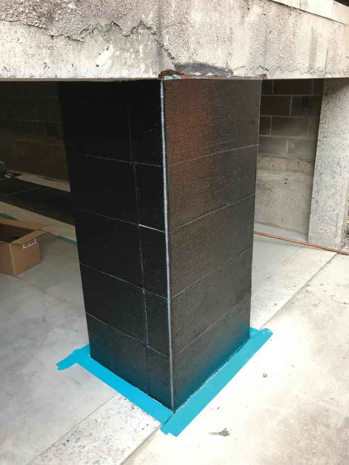
The Wing Building retrofits, which added strength using FRP (Figures 4-5), proved an effectively elegant solution – preserving floor space and most finishes. During exploratory investigations, the Design Team confirmed foundation sizes and depths and discovered an unusually high-water presence (Figure 6). During the design of the isolated building, the need for construction and permanent dewatering wells became apparent as the excavation would dig approximately 15 ft. below existing basement floor level.
Project Goals & Constraints
A master plan in the early 2000s identified the owner's desire to rehabilitate the Capitol complex to improve seismic safety and resiliency. The Oregon Constitution allows the governor funding authority without legislative approval for 30 days following an emergency. For this reason, the performance goal for the seismic renovation is to have the capitol building operational within 30 days following a seismic event so that the legislature can convene and continue its system of checks and balances throughout the response and recovery.
The construction of the Oregon State Capitol Renovation is being conducted in phases, with the final phase currently ongoing. The phased construction maximizes the efficiency of the legislature to continue meeting within the building – Oregon Legislature convenes annually: in odd years, “long sessions” lasting 160 days occur, while in even years, a "short session" lasting a maximum of 35 days is held.
This article is the first of three articles presented in STRUCTURE magazine that showcases the new retrofit of the Oregon State Capitol buildings. The next article will discuss the retaining walls creating the moat of isolation and those supporting existing permanently undermined buildings. It will also cover the foundation selection and design for performance and to work with the high water-table and other onsite problem solving. The final article will focus on the details of the seismic base isolated retrofit design, and construction. ■
MARCH 2024 29
Figure. 4. Analytical model rendering of the 1977 Wing with concrete shear walls (yellow) + FRP strengthened sections (red) at the vertical LFRS.
Figure 5. Reinforced concrete column strengthened with FRP. (Left) Full FRP wrap fabric around column. (Right) FRP anchors to actively terminate ends of the FRP wrap fabric.
John
McDonald, S.E. (john@catenaengineers.com) is a Principal with catena consulting engineers in Portland, Oregon
Figure 6. A high water-table combined with perched water visible was observed by Maya Foty, Historic Architect Extraordinaire and Mark Fitterer, Vintage Building Investigator.

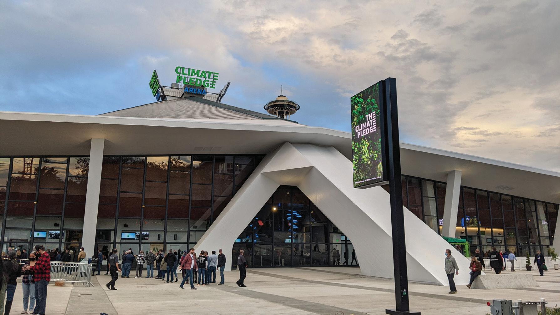
Preserving a Landmark
Using performance-based seismic design, the structural engineering team retrofitted the existing venue while maintaining the original 1960s feel.
By Brian MacRae, P.E., S.E.,Kerem Gulec, Ph.D., P.E., S.E.
STRUCTURE magazine 30

The ambitious goal of transforming the existing Key Arena in Seattle, Washington, into a world-class sports and concert venue was undertaken by its owners at Oak View Group, who challenged the project team to develop numerous innovative and collaborative solutions. Opened in October 2021, Climate Pledge Arena is home to NHL’s newest franchise Seattle Kraken and WNBA’s Seattle Storm. The total transformation of the venue serves as a structural engineering benchmark for existing building renovations in high seismic zones and demonstrates what can be accomplished with modern design and analysis techniques.
Following the classification of the existing roof and curtain wall as local landmarks by the Seattle Landmarks Preservation Board in 2017, the structural engineering team at Thornton Tomasetti was tasked with solving how to seismically retrofit the existing structure while not impacting the original early 1960s aesthetics, designed by modernist architect Paul Thiry. That challenge was complicated by the fact that the entire primary lateral force resisting system of the roof is composed of exposed concrete elements. The design team’s solution included developing a project-specific basis of design document and acceptance criteria and implementing a comprehensive state-of-the-art nonlinear dynamic analysis procedure. These procedures allowed the team to incorporate realistic analysis boundary conditions at the foundations, soilstructure interaction effects, and seismic fuses to control the
demands on the existing structure.
Given the confines of the historic curtain wall, aside from the new south glass atrium, which will welcome incoming sports and music fans for years to come, the only option to expand the arena to meet the needs of a modern venue was to extend the footprint an additional 15 feet below its current event level floor to construct four new steel framed levels and a parking garage at and below the existing grade. These new floors extend laterally beyond the original roof foundations and resist seismic loads through new concrete basement walls, shear walls, and buckling restrained braced frames. The interface of the existing concrete roof supports and the new below-grade floors occurs at the surrounding grade elevation at the upper concourse level. Over 680,000 cubic yards of soil was excavated and foundations for 20 Y-columns, eight chevron legs, and the south concrete buttress were demolished to allow for the below-grade expansion. New concrete walls and columns were installed to carry the gravity and seismic loads from the existing concrete elements another 55 feet down to new pile foundations. To support the excavation, 178,000 square feet of permanent shoring was installed composed of 500 soldier piles and 130,000 linear feet of tiebacks. The roof was underpinned on 67 temporary drilled shafts with over 3,700 tons of temporary steel installed spanning to the drilled shafts to resist seismic and gravity loads during construction (Figure 1).
MARCH 2024 31
Figure 1. The temporary roof shoring system comprised 67 temporary drilled shafts with more than 3,700 tons of steel.
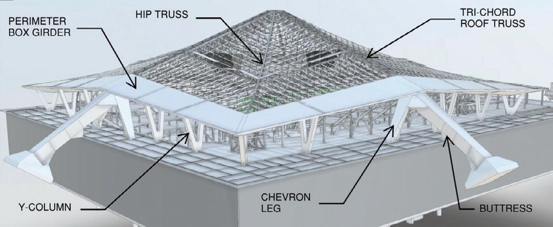
The Roof Structure and Its Load Path
The structural system of the existing 400-foot-x-400-foot, 44-million pound roof comprises four primary tri-chord steel arch trusses, which deliver gravity and seismic loads to four tapered trapezoidal concrete buttresses. Buttresses have maximum out-to-out dimensions of 12 feet x 12 feet and extend diagonally outward at the midpoint of the four sides of the square roof down to concrete spread foundations. An approximately 30-foot-wide by 14-foot-deep multi-cell post-tensioned concrete box girder is located at the perimeter of the roof. Spanning between the box girder and the tri-chord trusses are 272 infill trusses supporting a 1-1/2-inch bare metal roof deck. The perimeter box girder is supported by 20 Y-shaped columns at 20-foot on-center spacing and four pairs of large tapered trapezoidal concrete chevron braces oriented perpendicular to, and centered on, the four concrete buttresses. While the Y-columns resist a small percentage of the lateral forces, the buttresses and chevron braces resist most of the lateral loads. Further details of the structural system and gravity and lateral load paths can be seen in Figures 2 and 3.
Verifying Existing Conditions
The evaluation of any existing structure starts with an understanding of the construction materials and condition of the structure. Fortunately, original construction and renovation drawings, which included structural framing modifications, were available for the roof. This was crucial, as a much more substantial testing and investigation program would have been required to document the structural framing geometry, materials, and reinforcing details. Except for some connections from the minor


trusses to the perimeter box girder, the general condition of the landmark structure was good.
Existing building drawings were used to develop a SAP2000 analysis model of the building. Additionally, laser scanning was done to verify the existing conditions against the information obtained through the drawings.
Seismic Evaluation Approach
Seismic evaluation of existing buildings requires developing a project-specific evaluation and acceptance criteria using available standards such as ASCE 41 or available information in the literature (e.g., experimental data). A project-specific Basis of Design Report and a performance-based seismic evaluation approach utilizing applicable parts of ASCE 41-13 was used for the retrofit.
The arena is in a high seismic zone with nearby major faults that have the potential to generate large and destructive earthquakes. The closest to the site is the Seattle Fault, about 3 miles south. One significant design challenge was that the original roof was designed to significantly lower lateral force demands than the current-day building codes require. The design objective was to evaluate the seismic performance of the existing roof with current seismic hazards and retrofit as required to bring it to acceptable seismic safety and performance. In addition to the retrofits required for seismic deficiency, new loading was introduced onto the roof (e.g., rigging, scoreboards) as part of the renovation. Structural performance was evaluated at both the Damage Control level for BSE-1E (225-year return period) and Limited Safety for BSE-2E (975-year return period) hazard levels, satisfying the basic performance objective for an existing Risk Category III structure (BPOE).
A Probabilistic Seismic Hazard Analysis (PSHA) performed as
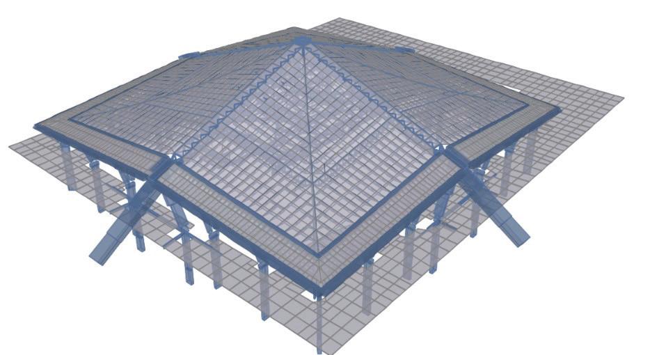
STRUCTURE magazine 32
Figure 2. This rendering of the roof structure shows components of the original roof structural system. Figure 3. Roof gravity and lateral load paths are illustrated.
Figure 5. Screenshot from SAP2000 model used for existing roof analysis.
Figure 4: Comparison between site-specific and USGS map-based response spectra.

part of the site-specific ground motion hazard study conducted by the geotechnical engineer, Hart Crowser, identified several other sources (local and distant faults) that contribute significantly to the overall seismic hazard at the site. The site-specific spectra accounted for local soil and geological conditions, including the Seattle Basin effects, which resulted in spectral accelerations of 25% to 50% higher than the ASCE 41 code-based spectra. For comparison, Figure 4 shows the two hazard spectra (code vs site-specific) for the same hazard levels.
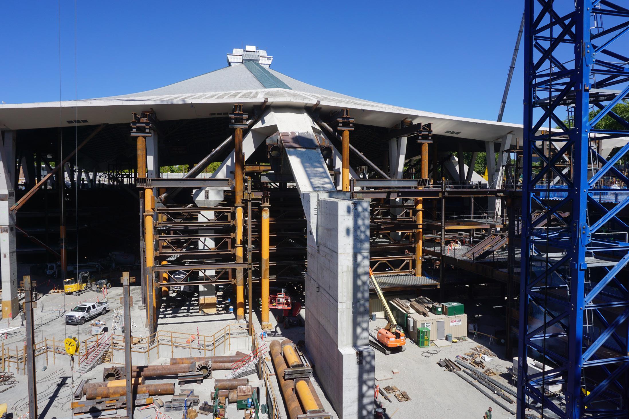
Subsequently, these spectra were modified to account for kinematic soil-structure interaction effects, which typically result in reduction of spectral acceleration demands at the short periods and do not impact acceleration demands on longer periods. At the period of the structure, this reduction was about 20%; therefore, some of the increases due to basin effects were offset by the application of kinematic soil-structure interaction effects.
Four analytical procedures are outlined in ASCE 41: linear static, linear dynamic, nonlinear static (pushover), and the nonlinear dynamic methods (listed in increasing analytical complexity). For the seismic evaluation of the roof, nonlinear dynamic analysis method was used, which is the most complex of the four methods, requiring by far the most analytical work. Use of complex performance-based seismic design procedures such as this one also requires an independent peer review in addition to the review of the Authority Having Jurisdiction (AHJ). This peer review team may include members from academia and industry practitioners with expertise in ASCE 41 procedures, including advanced analysis topics such as nonlinear dynamic analysis. Despite its complexity, this method was chosen due to the following reasons:
• The structure contains an unusual lateral force resisting system which is not listed as one of the Common Building Types described by ASCE 41. Nonlinear modeling of certain structural elements/actions were crucial, and in this case linear analysis methods would not be able to capture seismic behavior reasonably. A nonlinear behavior will allow realistic modeling of boundary conditions for the buttresses and fuses in the new substructure that will be used to limit the tension forces in the chevron braces.
• Nonlinear dynamic procedure (or nonlinear response history analysis) is the most accurate analysis in predicting seismic behavior. Considering the significance of the structure, it was thought to be the most appropriate analysis method. In essence, nonlinear dynamic procedure requires creating a nonlinear analysis model of the building and subjecting that analytical model to ground motions developed by the geotechnical engineer, specifically for that site and building. At that time, seven ground motion records were allowed by ASCE 41-13 and were used (current practice is using 11 ground motion sets). These acceleration records included two horizontal components of the shaking and the vertical component.
For most buildings, vertical acceleration records are not explicitly used in design. However due to the unique framing (long span, sloping trusses, etc.), it was decided early that vertical accelerations would need to be explicitly captured in the analysis. This also requires a more refined analytical model, as a sufficient number of vertical vibration modes, typically not critical for the seismic design of most buildings, need to be captured.
Analytical Modeling & Soil-Structure Interaction
A 3D mathematical model was created in SAP2000 to analyze the roof that included all the primary structural components of the existing structure, the new rigging grid, and the new upper concourse diaphragm, as shown in Figure 5. A separate linear dynamic analytical model was developed in SAP200 for analyzing the new below-grade
MARCH 2024 33
Figure 6. Nonlinear force-deformation curves for the north, east and west buttress spread footings.
Construction on the project was completed in 2021, and the new Climate Pledge Arena officially opened October 2021.

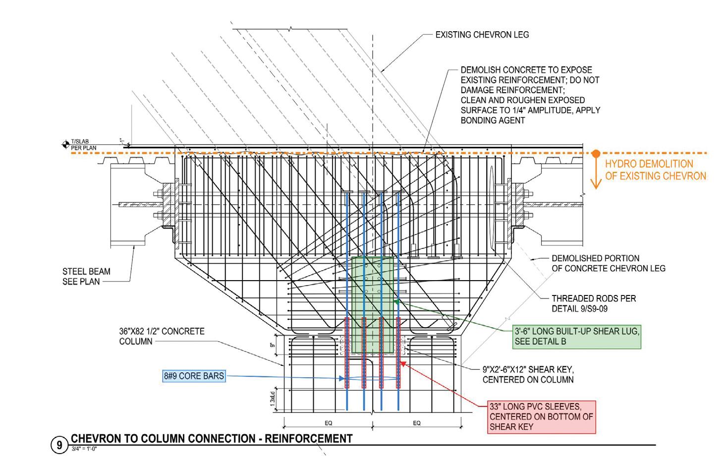
portions of the arena. Transfer loads from the existing roof model were superimposed onto the base-structure model to study the full load path through the new below-grade lateral system. The existing roof analytical model was quite heavy, with 600 nonlinear links, and 10,000+ frame and 6,000+ shell elements. The roof truss elements and columns were modeled as line elements. The roof deck and box girders were modeled using thin shells. The model also had to include a newly introduced rigging frame, which was laterally stabilized to the roof using buckling restrained braces.
Nonlinear actions like the fuses introduced in the new substructure under the base of the chevrons and interaction of the buttresses with soil were modeled explicitly. Further details of the chevron fuses can be found in the design and construction section below. The north, east, and west buttress spread footings were modeled using nonlinear force-deformation curves with both translational and rotational stiffness (Figure 6). The interaction of the structure, foundation, and supporting soil-structure interaction (SSI) is an important feature of the mathematical model which can impact the demands imposed on the structure for a simulated earthquake. The sensitivity of the structural response was tested by varying the foundation stiffness parameters from the calculated values determined in accordance with ASCE 41.
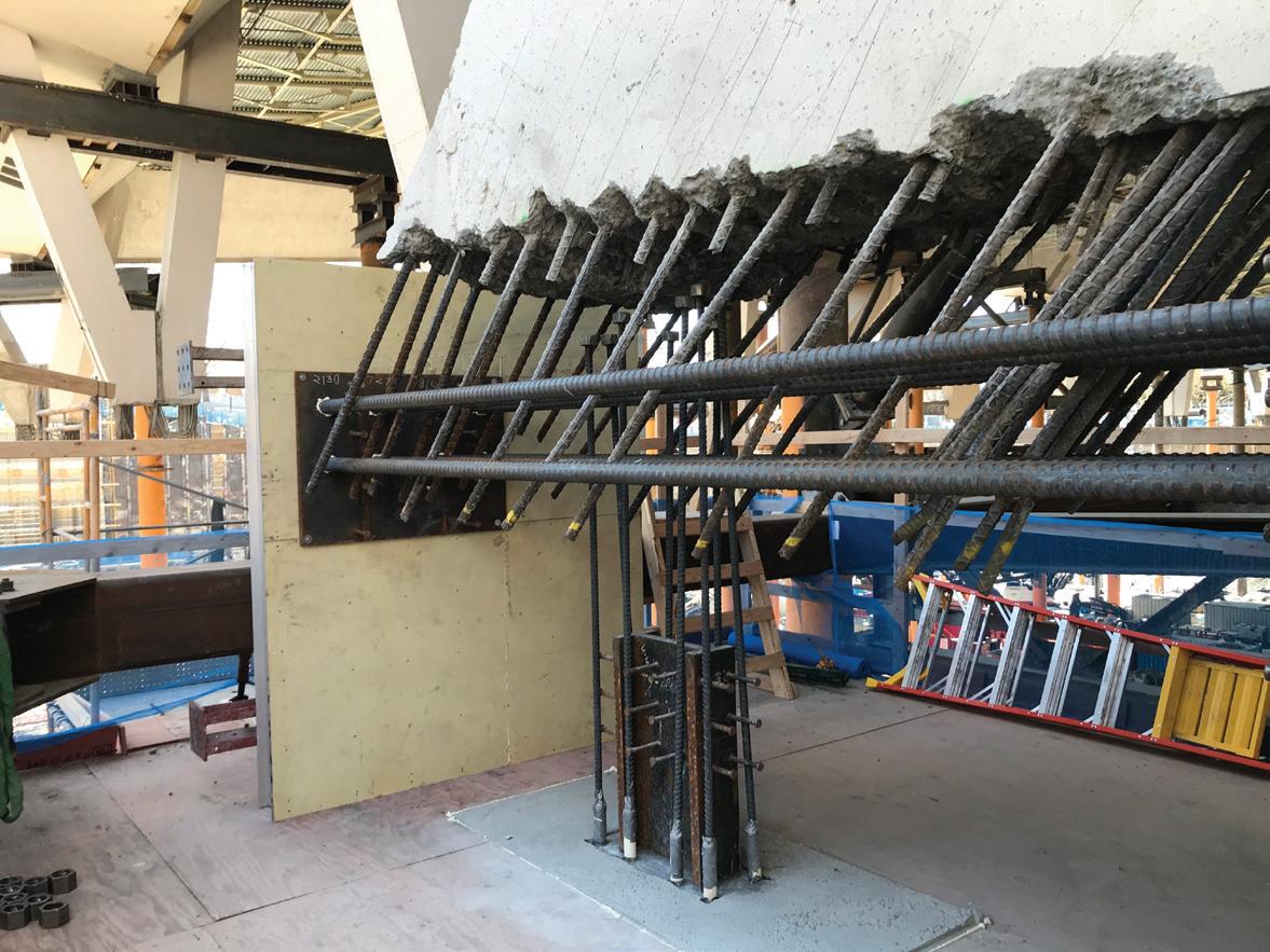
Analysis Workflow
Considering the size and complexity of the project, design and construction schedules were very aggressive. As previously explained, nonlinear response history analysis was deemed appropriate for the seismic analysis, a procedure that required significantly more analysis and pre- and post-processing time than conventional linear procedures. It was clear from the beginning that the analysis and post-processing workflows had to be very efficient and flexible. A significant number of analysis iterations was expected to quickly study new additions/ modifications and evaluate effectiveness of the considered retrofits. At each iteration, a full set of ground motions was run, and results were quickly developed and screened to verify if intended changes were viable. Project-specific post-processing scripts were written in the Python programming language to enable quick and efficient visualization of results. An example of these outputs is shown in Figure 7.
Design & Construction
In hockey, a team can have a meticulous game plan, simulated through reps on the practice ice. However, success is ultimately gauged by how the team executes this plan when the fans fill the seats and the puck drops. Similarly with a structural team, a sophisticated and accurate analysis approach and model provide little value to the finished project if they do not translate into a cost-efficient and constructable solution executed by qualified tradespeople. The successful seismic retrofit of Climate Pledge Arena would not have been possible without the collaborative execution of the team led by owner OVG, owners representative CAA Icon, architect Populous, structural engineer Thornton Tomasetti, and construction manager Mortenson.
The most challenging conditions to resolve were at the interface of the roof’s concrete elements with the new steel bowl and garage structure, at and below grade. To preserve the roof’s aesthetics and limit the number of retrofits required within the existing roof trusses, the design team strived to limit changes in the roof’s lateral load path to the full extent possible.
One such interface condition is where the four pairs of chevron
STRUCTURE magazine 34
Figure 7. Data visualization example showing utilization ratios of existing roof truss members.
Figure 8. Structural detail of chevron node at upper concourse.
Figure 9. Ductile fuse at base of chevron node.

braces meet the new upper concourse steel composite floor framing at the existing grade level. At this interface, a concrete node measuring 13 feet x 6 feet 8 inches was designed to fully capture the angled chevron leg from above and transfer loads to the horizontal collector beams in the upper concourse diaphragm and the new 7-foot x 3-foot concrete column below. This new column would transfer the vertical reaction to a new pile foundation 55 feet below grade. The existing chevron legs had limited tension capacity which the design team resolved by designing a fuse in the new node to limit the tension forces that could be delivered through the chevron leg. This was accomplished by installing eight #9 bars vertically in unfilled 33-inches long PVC sleeves to allow both ductile yielding and the force to be capped by the post-yield capacity of the bars. To finish out the detailing of the node an embedded steel shear lug was designed to transfer shear loads across the fuse interface. Additionally, eight #18 Grade 80 Dywidag threaded rods were installed horizontally through the node to transfer seismic forces to the steel collectors in the upper concourse. The existing reinforcing in the chevron brace was preserved using hydrodemolition techniques to be developed into the new node. Hydrodemolition consists of blasting the existing concrete with high-pressure water exceeding 20,000 psi using a robot. It has the effect of removing all concrete and exposing the existing reinforcing undamaged to allow for embedment into new freshly poured concrete.
As the design efforts progressed, the structural team discovered that the new boundary conditions for the roof were introducing excessive shear and torsion forces in the Y-columns due to their unique geometry and connection to the bowl framing below. These existing columns were minimally reinforced for shear. While introducing a fiber wrap solution to resolve the issues in the Y-columns was considered, it was deemed infeasible due to the aesthetic requirements. As such, the design team developed a solution to laterally release the Y-columns from the upper two levels of the new below-grade framing using low-friction slider connections at each steel beam to Y-column connection. This solution had the effect of lengthening the Y-column’s unbraced length, and in turn, reducing its stiffness and ability to attract seismic loads. This creative solution resulted in all 20 Y-columns being able to withstand the seismic forces induced by the roof displacements and eliminated all retrofits of the existing Y-columns.
After the design challenges at the roof/bowl interface were resolved, the design team focused on the seismic retrofits required within
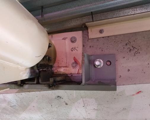
the existing roof steel. The new rigging grid, capable of supporting shows of up to 200,000 pounds, was seismically braced to the existing roof trusses using Buckling Restrained Braces (BRB). This reduced the number of required steel retrofits by limiting the forces that could be delivered from the grid to the existing steel roof. Retrofits throughout the roof were primarily truss web and chord strengthening through additional welded and bolted steel plates, channels, and angles.
One connection of concern in the existing roof was at the infill truss to perimeter box girder connection (Figure 11). It consisted of a steel plate flush with the face of the box girder with four expansion bolts. This connection was found to be susceptible to premature failure under axial load in a large seismic event. To remedy this, a catch shelf was designed below the connection to support the truss in case of anchor failure, and a nonlinear link was introduced in the analysis model to represent the condition. Without nonlinear analysis techniques, accurately modeling the behavior of the final solution would not have been possible.
Conclusion
Climate Pledge Arena is an award-winning retrofit and rehabilitation project unlike any other. The complexities and challenges involved with temporarily supporting a 44-million-pound roof in the air while building a completely new arena below was a monumental feat of engineering, design, and construction. Utilizing modern techniques in nonlinear analysis and performance-based design, the structural design team was able to develop creative and innovative engineering solutions without limitations. While such an analysis procedure may not suit every project due to the potential impact on schedule and design fees, it can be an incredibly valuable tool for an experienced structural engineer dealing with complex and unique building structures. ■
Brian MacRae, P.E., S.E. is an Associate Principal with Thornton Tomasetti in Seattle, WA. He can be reached at bmacrae@ThorntonTomasetti.com
Kerem Gulec, Ph.D., P.E., S.E. is a Principal with Thornton Tomasetti in Los Angeles, CA. He can be reached at cgulec@ThorntonTomasetti.com
MARCH 2024 35
Figure 10. (left) Beam to Y-column slider connection.
Figure 11 (above). Infill truss to box girder catch shelf retrofit.
Revitalizing Oakland’s Beaux-Arts Tapscott Building
A vacant structure returns as a functional portion of downtown while maintaining its historic appeal.
By Zack Kardon P.E. and Viral Vithalani, AIA

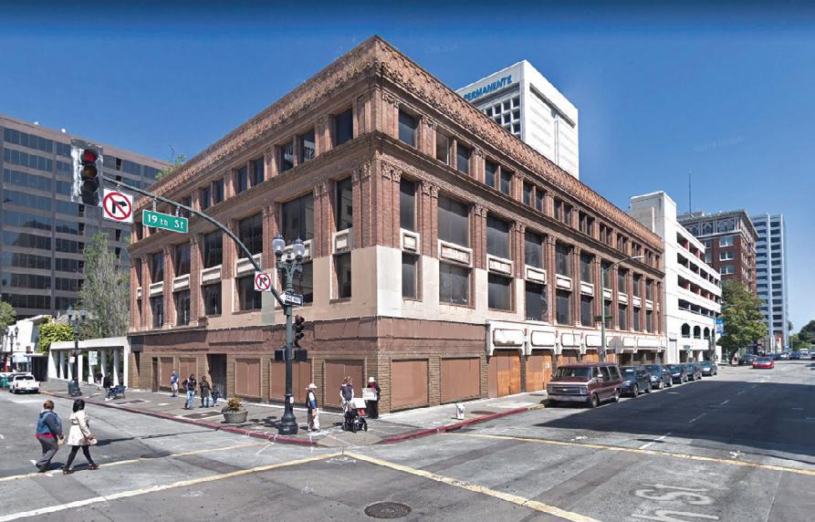
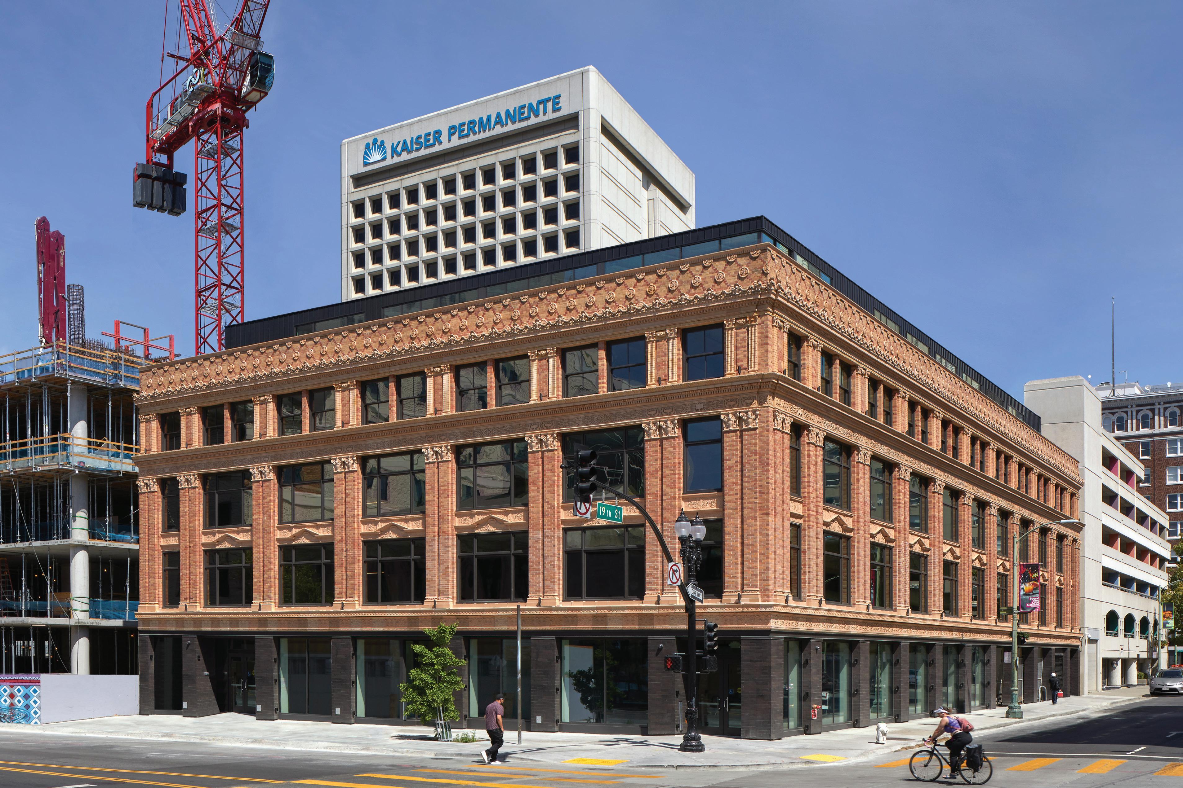
After more than three decades of disuse, the Tapscott Building, one of the oldest edifices in the northern part of Downtown Oakland, California, known as Uptown, has a new lease on life. The steel and concrete structure built by local developer Ernest N. Tapscott opened in 1922 and featured four stories plus a basement that housed offices, shops, and a theater. Located at the corner of 19th Street and the city’s bustling Broadway corridor, the brickclad Beaux-Arts building attracted tenants like Standard Oil Company and a public market. Over the years, tenants ranged from Kaiser Permanente to a morgue. In 1989, the Loma Prieta earthquake struck and severely damaged the Tapscott. Demolition of the rear part of the compromised theater left a seismically unsafe L-shaped building with an irregular and highly torsional structure. The Tapscott Building sat red-tagged and lifeless for 30 years.
Real estate investment company Rabin and developer Seth Hamalian purchased the property in 2012 with the goal of renovating it for contemporary retail and office use while restoring the historic brick and terra cotta exterior. The Tapscott’s location directly above and adjacent to the 19th Street Bay Area Rapid Transit (BART) Station and tunnel enhanced the building’s
STRUCTURE magazine 36

Completed in time for its centennial, the rehabilitation of The Tapscott Building leverages sensitive structural solutions designed to transform the historic structure for modern use while balancing the unusual constraints of its location with preservation priorities. On the opposite page, a historic photo is shown, along with a photo of the building prior to renovation, after three decades of abandonment.
Owner: Rabin and developer Seth Hamalian
Structural Engineer: Murphy Burr Curry, Inc.
Architect: TEF Design
Contractor: Alston Construction
Civil Engineer: BKF Engineers
Mechanical/Plumbing/Fire Protection Engineer: Acco
Electrical/Telecom Engineer: Helix
Building Envelope: Walter P. Moore
MARCH 2024 37
Project Team
appeal for commuters and helped to shrink its environmental footprint. They also purchased the adjoining two properties, which they entitled for a 39-story, mixed-use residential high-rise next door to the Tapscott, as well as underground parking and a pedestrian plaza between the two structures. The new tower is being built by developer Behring Companies.
Adapting a Seismically Unsafe Structure for Contemporary Tenants
Rabin and Hamalian sought to maximize the openness and flexibility of the floor plans for future tenants, removing non-historic partitions and ceilings and allowing natural light to flood the interiors. The goal was to place 5,000 square feet of retail space on the first floor and 24,000 square feet of office space on floors two, three, and four. Adding a contemporary 5,000square foot penthouse and a 2,300-square foot roof deck with views of the nearby Fox and Paramount theaters heightened the project’s complexity.
The Tapscott building had no lateral force resisting system, relying on only the perimeter walls along 19th Street and Broadway. A comprehensive facility evaluation revealed that a new lateral system to meet current code was needed, as well as the insertion of three drive aisles on 19th Street so that vehicles could access the neighboring tower.
As the structural engineer of record, Murphy Burr Curry, Inc. (MBC) faced the challenge of addressing building deficiencies while maintaining the historic street-facing facades along Broadway and 19th Street and developing solutions that would support the desired floor layout. While placing wall panels or braces along the street-facing building facade would have been less complicated and more economical, visible braces or panels would have compromised the historic brick exterior, interrupted the floor plates, and interfered with the drive aisles. By collaborating closely with the architect of record TEF Design (TEF), the team ensured structural solutions did not interfere with the building’s program, enabling restoration of historic fabric in a sensitive and contextual manner.
To strengthen the ground floor at the 19th Street side of the Tapscott beneath the three new drive aisles—one for entry to the neighboring tower building, one for egress, and one for the tower’s loading dock—steel beams were added to the slab’s underside.
Structuring Shear Wall Solutions
MBC worked with TEF to devise a solution that introduced a central C-shaped reinforced concrete shear wall core, inserted reinforced concrete shear walls at each of the four non-street-facing elevations, and reinforced portions of the existing pier and spandrel moment-frame bays where required to increase their seismic force-resisting capacities.
Because the site occupies a seismically active zone, the possibility of adding a fifth-floor penthouse required careful analysis of building loads. Keeping the structure only four floors in height would have permitted MBC to analyze the building for a minimum of 75 percent of the Design Basis Ground Motion, as defined in the California Existing Building Code. Adding a fifth floor meant that the team would have to design to 100 percent of the Design Basis Ground Motion, requiring significantly more strengthening. Ultimately, the owner decided to add the fifth-floor penthouse office space.
To create an exterior roof deck and support the fifth-floor penthouse, the existing reinforced concrete roof was replaced with a new concrete-on-metal deck supported by new structural steel beams that stiffen the existing slender octagonal columns.
Adding the fifth-floor penthouse and rooftop deck, as well as a first floor restaurant space, also changed the building occupancy classification from B to both A and B. This occupancy change required the building to meet a
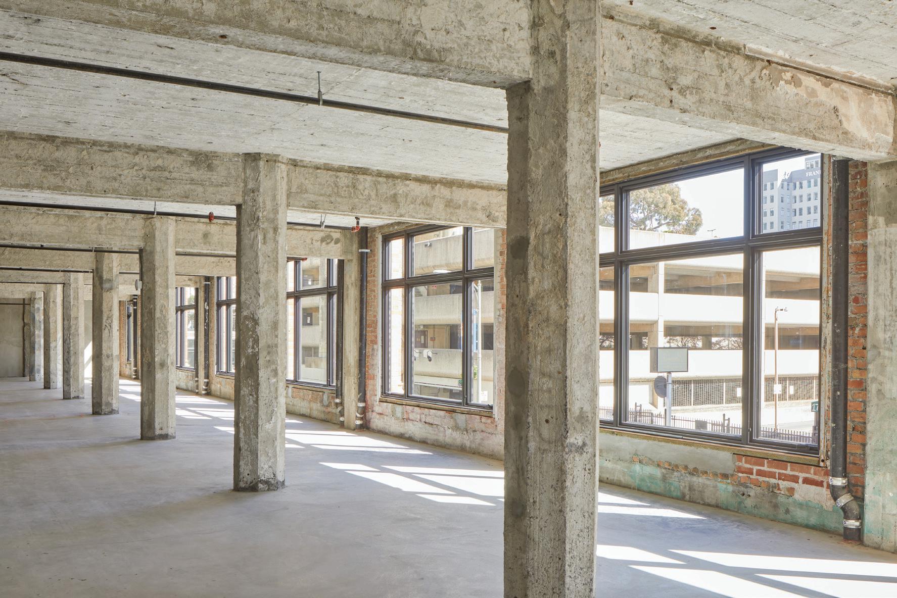
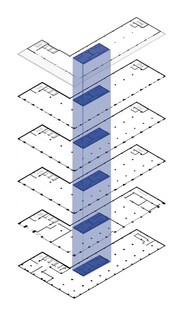
stricter fire-resistance standard. Because the existing wood-framed secondfloor mezzanine did not meet that standard, MBC and TEF decided to demolish the mezzanine and reframe it with steel and lightweight concrete on metal deck.
Oakland’s Planning Department required the new penthouse to be set back from the street so as not to be visible from the sidewalks below, in keeping with preservation mandates. TEF, working closely with MBC, designed the penthouse as a glass box to bring in plenty of natural light and provide a spacious, open feel, while devising a structural solution that
STRUCTURE magazine 38
Existing non-historic interior partitions and ceilings were removed to create an open canvas for incoming tenants while leveraging the authentic beauty and texture of the structure.
A 12-inch thick, heavily reinforced concrete core—efficiently consolidating restrooms and utility shafts—was added to provide lateral strength, eliminating the need for bulky brace frames around the building’s perimeter, and preserving unobstructed exterior views.

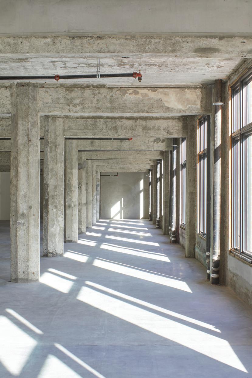
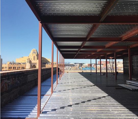
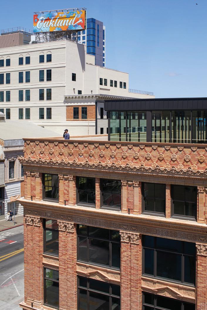

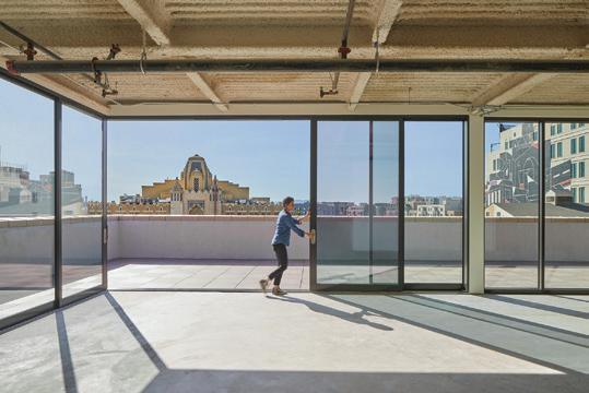



would not compromise the penthouse’s transparency. The design team chose shear walls and placed them strategically in the penthouse framing to avoid the need for visually distracting brace frames and solid walls.
Satisfying BART’s Stringent Requirements
Oakland’s Planning and Building Department approved the renovation plan, with the provision that the owner would have to also secure BART’s
approval. BART required substantial modifications to the structural design to show that the proposed building alterations and retrofit would in no way add any vertical or lateral loading on the existing adjacent tunnel or station structure.
The team found a way to address BART’s stringent requirements without compromising the client’s need for unimpeded floor plates. The structural design incorporates micro piles, which transfer vertical load below the depth of the BART tunnel, and a series of grade beams combined with a four-footthick reinforced concrete mat slab, which resist the building’s lateral loads
MARCH 2024 39
Strategically placed shear walls in the penthouse framing (during construction, left, and completed, right) enabled the development of a light, transparent, distinctly modern addition to the rooftop, in keeping with
The rooftop addition (actual-left, top right and as rendered-bottom right) is a transparent, glass and metal penthouse—set back from the parapet and minimally visible from the street below. The design creates a communal indoor and terrace space for building tenants with views to the City skyline and nearby cultural landmarks. It features large sliding glass walls at the southwest corner that open up the penthouse to al fresco experiences.
A B
The Tapscott Building’s location adjacent to and above the 19th Street BART Station/Tunnel (marked in plan A, below) required a sensitive and unconventional solution. Micro piles (below) and in section (B) were added at 60-foot depths to avoid exerting pressure on the subway tunnels below, and steel beams were also added to stiffen the existing slender octagonal columns.
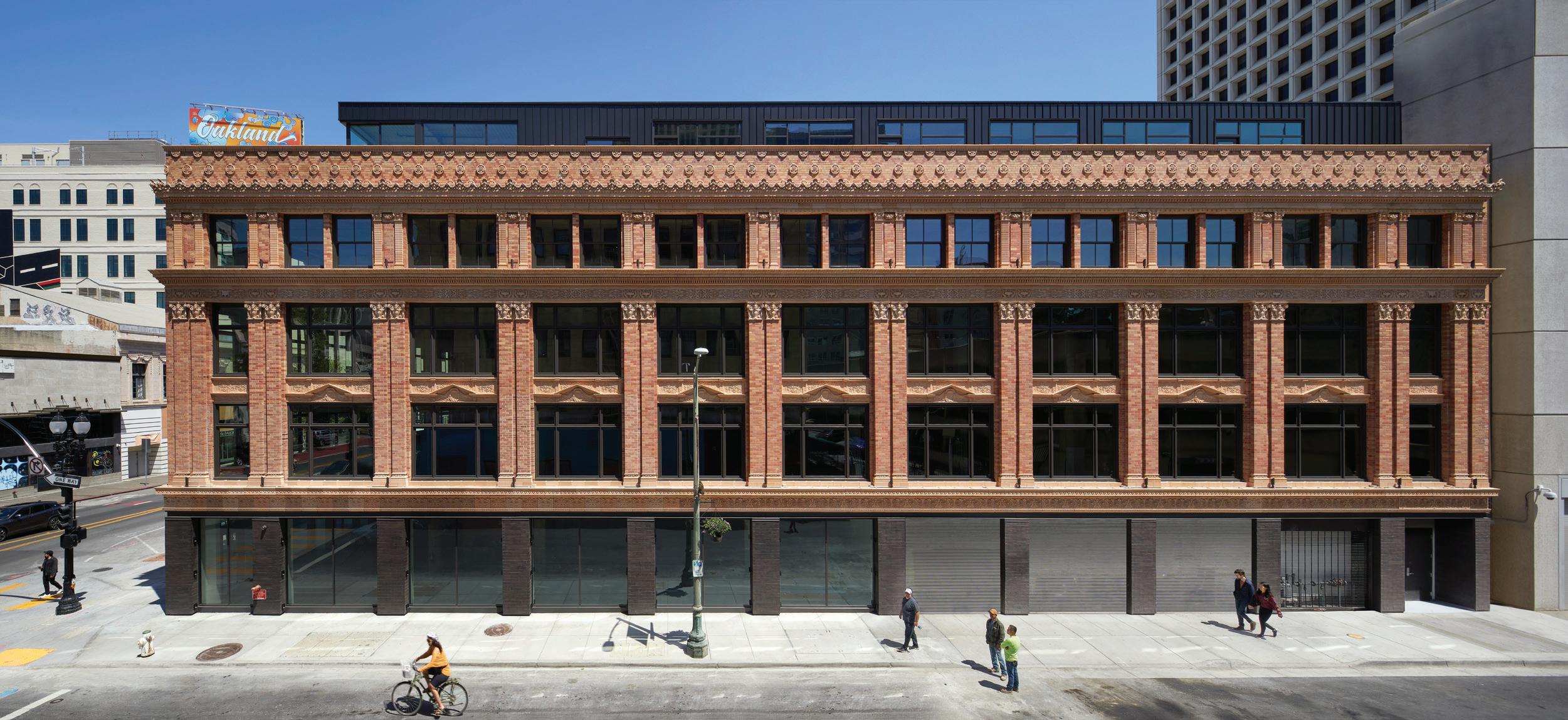
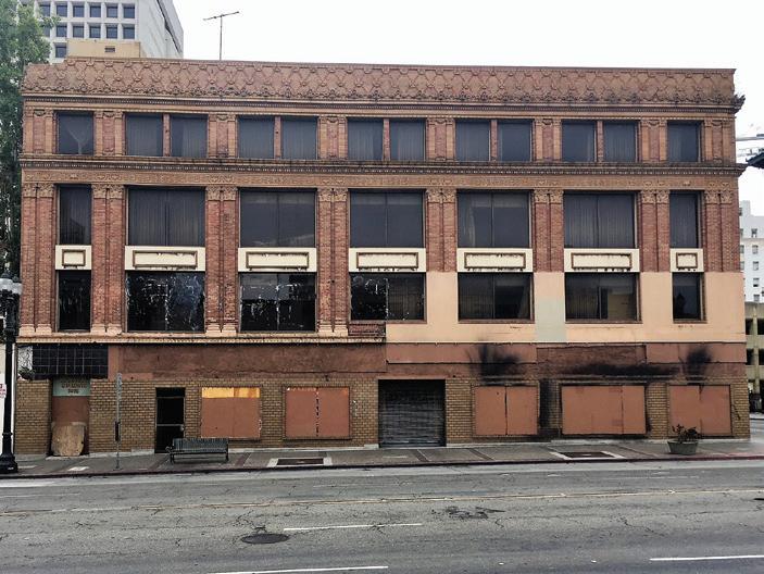


STRUCTURE magazine 40
Copyright © 2024 DEWALT ANCHORS APPROVED IN CRACKED AND UNCRACKED CONCRETE INCLUDING SEISMIC AND WIND LOADING SUBMIT DEWALT ANCHORS FOR YOUR NEXT PROJECT CRITICAL CONNECTION UNDERCUT+ ™ ICC-ES ESR-4810 SCREW-BOLT+™ ICC-ES ESR-3889 QUALIF I C ATION SEISMIC REGION
Adding beams on the second level allowed the team to realign incongruous vertical pilasters between the ground level and upper floors of the existing structure (right). The completed project (above) restores the original symmetry of the historic facade, featuring new street-facing retail/restaurant space with glass fronted storefronts, meant to energize the sidewalk and connect pedestrians to the life of the building.
at the foundation level, outside of the BART tunnel’s zone of influence. Within the zone of influence, the slab at grade is essentially cantilevered. The micro piles extend to 60-foot depths to avoid exerting pressure on the subway tunnels below. The bond length ranges from 30 to 90 feet.
Restoring Historic Fabric and Enhancing Visual Appeal
Over the building’s life, renovations had compromised some of the historic aspects of the building, and some of the original elements had been lost as well. The design team worked together to repair unsightly modifications and replicate missing terra cotta pieces. A previous renovation had altered the building’s pilasters on the ground floor along Broadway, so that they did not continue down at the first floor. Adding beams at the second floor helped transfer loads so the vertical lines of the pilasters could continue seamlessly at the ground-level elevation.
Approximately 70 percent of the building’s historic terra cotta cladding had been lost or damaged over the decades. TEF collaborated with the building envelope consultants to recreate the missing terra cotta pieces with glass fiber reinforced concrete (GFRC), using historic molds from detailed façade surveys and mockups. The team also replaced the existing sheet metal spandrel between the windows on floors two and three with a GFRC spandrel. MBC collaborated on all this work to determine the weight the restored façade would add to the structure and identify the best way to affix the new GFRC panels, which were attached with steel embeds.
In between the Tapscott Building and the adjacent 39-story residential
tower is a new 20-foot pedestrian plaza leading to the tower’s four-story podium which occupies the former site of the theater at the rear of the Tapscott and houses new office space and recreational amenities for the residential tower units above.
The renovated Tapscott is windowless on the plaza and podium facing side, and features restored historic advertising signage painted on the concrete exterior for viewing by those passing by on Broadway. Along Broadway and 19th Street, the brick and terra cotta exterior and the original Beaux-Arts parapet, spandrels, and cornice have all been restored. Acoustic screening mitigates noise from rooftop mechanical equipment.
For more than three decades, the Tapscott Building has sat vacant and unusable on a prominent street corner of downtown Oakland. With the completion of the renovation in 2022, this historic mixeduse structure returns as an active player on the streetscape, integrated with a new residential high-rise next door to help contribute to the revitalization of this stretch of Broadway. The sensitive seismic solutions ensure that the building will not affect BART’s station and tunnel below in the event of an earthquake, while also maintaining the aesthetic and the appeal of the historic brick exterior.■
Zack Kardon, P.E is a Principal with Murphy Burr Curry, Inc.(located in San Francisco, California) with over 23 years of structural design experience. (zkardon@mbcse.com)
Viral Vithalani, AIA is an Architect with TEF Design (located in San Francisco, California) with over 23 years of experience. (viral@tefarch.com)

MARCH 2024 41
Total Conformity Assessment Solutions® • Over 90 years of industry experience • Experts in building product testing, inspection and certification • Acceptance Criteria development for innovative products • Trusted by code officials for ease in approvals and installation www.icc-es.org | 1-800-423-6587 24-23438 Look for the Mark!
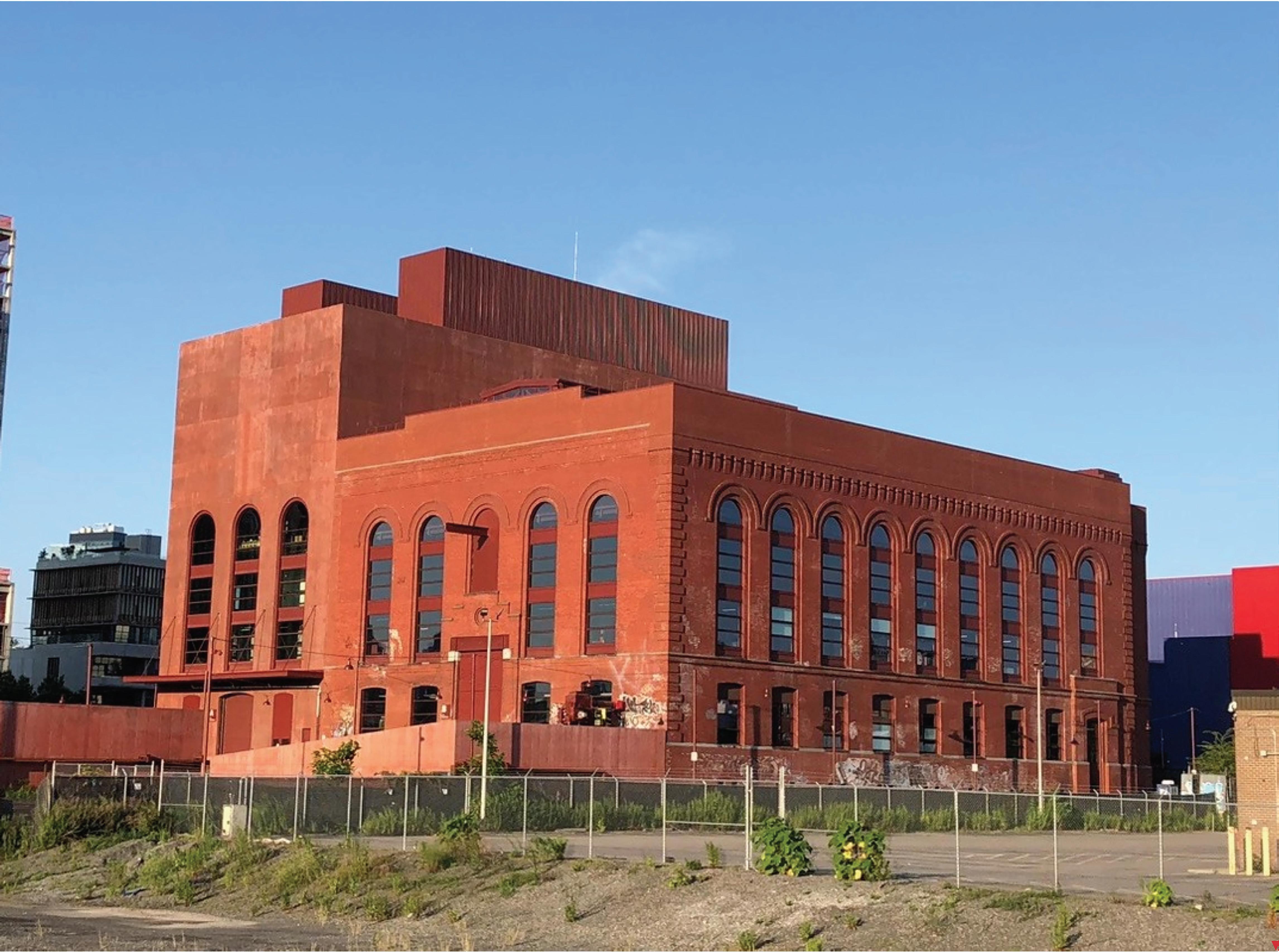 Completed project. Photo courtesy of Silman.

Brooklyn Powerhouse
A historic foundation is brought back from the dead.
By Eytan Solomon P. E., LEED AP, and Richard Lo P. E.
Powerhouse Arts in Brooklyn, New York is a $180 million adaptive reuse project that included extensive renovation and new construction—culminating in 170,000 square feet for fabrication shops, educational facilities, community programs, and multifunctional event space. The project entailed repairing the 55,000 square-foot original steel-and-masonry Turbine Hall, adding a new 3-story, 40,000 square-foot infill structure of cast-in-place concrete within the Turbine Hall volume, and adding a new 6-story 75,000 square-foot Boiler House structure of castin-place concrete; all three structures are seismically connected. This article focuses on the history and process of justifying reuse of existing foundations at the site, which was critical to the project.
The site, at 322 Third Avenue in Brooklyn, was originally developed and used as a power station for the Brooklyn Rapid Transit (BRT) System. The main original buildings at the site constructed around 1900 were the Turbine Hall and Boiler House, which abutted each other and shared a party wall. The Boiler
Project Team
Architect: PBDW Architects
Design Consultant: Herzog & de Meuron
Structural Engineer: Silman
Geotechnical Engineer and Site Civil Engineer: Langan
MEP Engineers: Buro Happold Consulting Engineers, P. C.
Construction Manager: Urban Atelier Group
Landscape Architect: Ken Smith Workshop
Lighting Designer: Tillotson Design Associates
Civil Engineer: Philip Habib &Associates
Environmental Engineer: Roux Associates
AV, IT, Security: Shen Milsom & Wilke
Theater Consultant: Charcoalblue New York
Facade Consultant: Reg Hough Associates, LLC, Eckersley
O’Callaghan, Integrated Conservation Resources, Inc.
Acoustical: Longman Lindsey
Elevator: VDA Elevator Consulting
MARCH 2024 43
House superstructure was demolished in the 1950s, while the Turbine Hall (and the party wall) were left in place.
The new project proposed adding back a new Boiler House structure in the footprint of the original and adding a new Turbine Hall infill structure. In deducing from historic drawings, it was believed that the Turbine Hall and the Boiler House were founded on a single monolithic, very thick (6+ feet) concrete mat slab supported by a dense grid of piles.
It was critical to the economic feasibility of the project for these new structural loads to be supported by the existing foundation without significant reinforcement or new deep foundations, due to the extreme soil contamination at the site— being adjacent to the notorious Gowanus Canal. Resulting from the deep thickness of the mat, the groundwater level, and environmental concerns, exploratory probing through the mat to directly load test individual piles was not feasible.

Because the original Boiler House building had been demolished, and no original pile records were located, the governing building code (NYCBC 2014, section 1808.2.7) explicitly limited new loads on such existing piles to no more than half the calculated previous loads on the piles—unless load testing were performed. Half the previous load would have been far too restrictive for the proposed project, therefore the team pursued gross load testing of the piled mat foundation as a system.
NYCBC 2014, 1808.2.7 Use of existing piles. Piles left in place where a structure has been demolished shall not be used for the support of new construction unless the piles are load tested, original installation and testing records are available, or the new loads are no more than half the calculated previous loads on the piles. The engineer shall determine and certify that the piles are sound and meet the requirements of this code.
Silman (the project’s structural engineer) and Langan (the project’s geotechnical engineer) led a campaign to justify the new project loads on the existing foundation, which entailed: structural analysis, geotechnical investigation, foundation grout injection, and load testing, all under ultimate review by the New York City Department of Buildings (NYC DOB) (the Authority Having Jurisdiction) as a CCD-1: “Construction Code Determination”, i.e. a code variance.
Structural Analysis
The existing original Turbine Hall structure—composed of brick masonry walls, steel framing and concrete slabs—exhibited deterioration from water infiltration and vandalism, but showed no discernible signs of damage specifically from foundation settlement. As alluded to below, there was undocumented, non-original construction and backfill present in the building before the current project. Silman calculated the original, existing pre-project, and proposed project loads—for presentation to the team and the NYC DOB.
It was impossible to directly observe the current condition of the mat slab except at very limited exposed areas, and the team did
not have information as to whether any settlement occurred when the post-original additional loads i.e., when the Turbine Hall infill structure and topping layers, and the Boiler House soil backfill were added. However, given the estimated existing loads, the inferred former loads, and that the existing original Turbine Hall brick masonry showed no discernible signs of damage specifically from foundation settlement, it seemed reasonably possible to justify a certain amount of load carrying capacity for the existing foundation. Per discussion with Langan, Silman established the strategy of load testing on top of the existing mat with 1.5 times (per ASTM D1143 reference) the effective additive area load; per discussion with NYC DOB, this safety factor was increased to 2.0.
At the Turbine Hall especially, this load testing would be additionally conservative because the existing infill structure and existing topping slab and soil would also still be in place during the load test. These elements would be removed for the current project construction, but for expediency they were left in place during the load test. Additionally, Silman calculated an estimate of an individual existing pile’s load based on the historic drawing cross section which showed the existing piles spaced at 2.5 feet each direction. The required capacity per pile (including the loads from the current project) was approximately 10 tons unfactored axial load per pile.
Geotechnical Investigation
While very little original design documentation was available, several historic articles provided clues about the existing foundation. Langan oversaw the execution of 13 conventional site borings, five test pits at the edges of the mat to view the mat and expose a total of eight pile conditions, two groundwater observation wells, and five seismic cone penetration probes. Additionally, ground-penetrating radar (GPR) scanning was conducted by GB Geotechnics across the accessible topside of the mat slab, to locate under-slab voids as much as could be determined with limited non-destructive testing. With these characteristics of the existing foundations, soils, and
STRUCTURE magazine 44
Photograph of the BRT Powerhouse in 1916, taken from the Gowanus Canal (Urquhart, 1916).

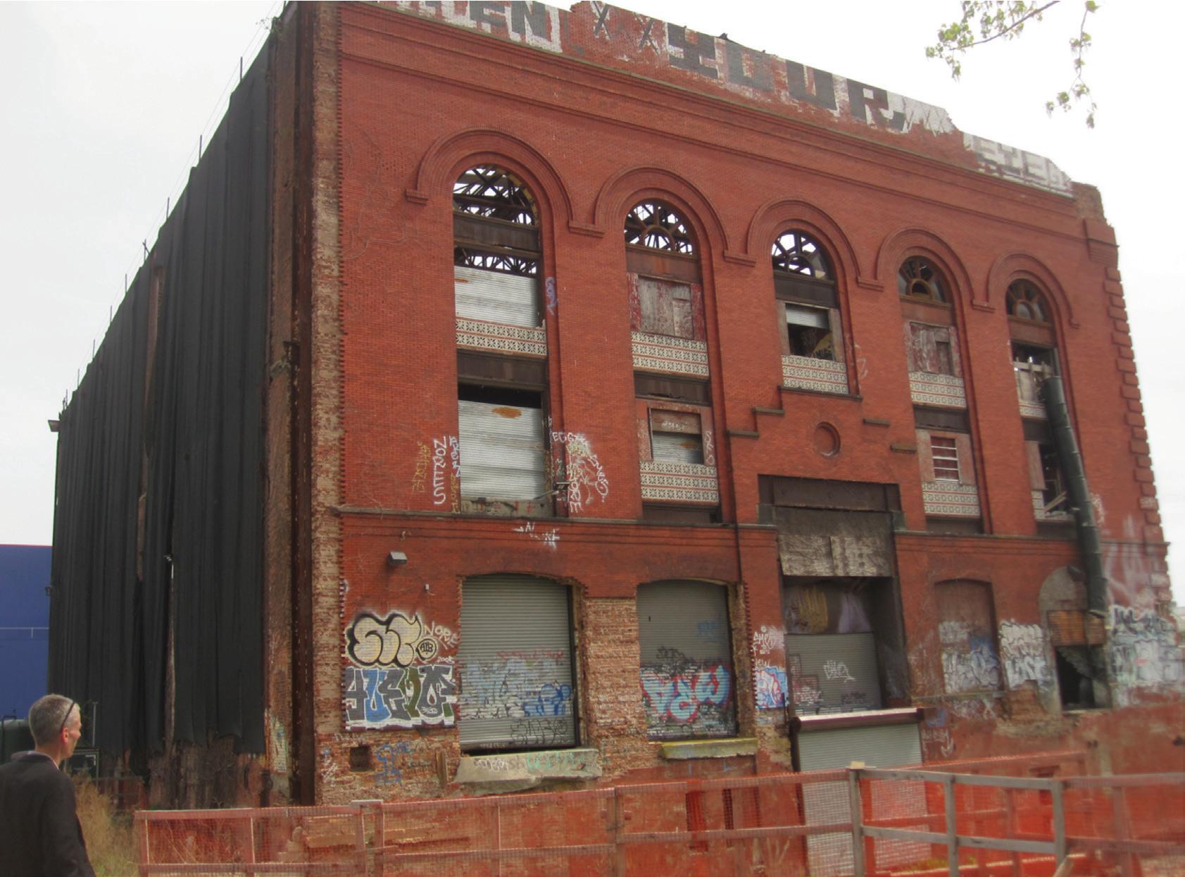
voids, Langan performed an analysis of vertical loads on the pile-raft foundation based on a simplified analysis of pile-raft foundations described by Poulous. The method provides an assessment of the overall load-settlement behavior of the foundation where piles are uniformly spaced under a raft (or mat). The method uses the stiffness of individual piles and stiffness of the raft to calculate an overall stiffness of the pile-raft foundation system and estimate load-settlement behavior.
The analysis found that the loads were supported in a shared fashion between the piles and mat as a bearing mat slab: approximately 60% by the piles and 40% by the mat slab bearing. To improve the mat
slab bearing and to improve protection of the piles, the team pursued a foundation grout injection campaign prior to the load testing.
Foundation Grout Injection
The cause of under-slab void formation is unknown, but may have been a result of the soft sediments underlying the raft settling over time due to groundwater level changes while the pile supported portion remained in place. The voids were planned to be filled in order to engage the soil subgrade under the piled raft, so that the foundation would be supported by the combined action of shallow bearing and the pile field.
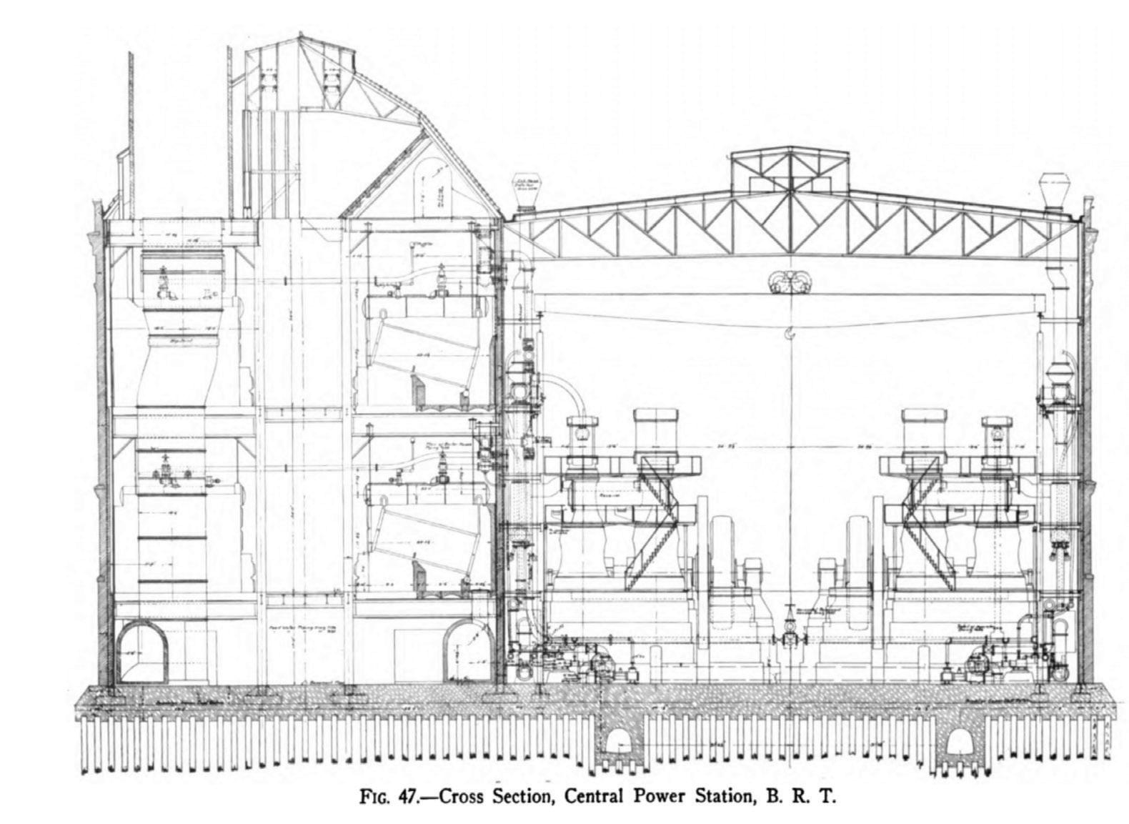
Grout injection ports were installed at approximately 5-foot on center spacing across the full mat slab—both in the Turbine Hall and Boiler Hall—with closer spacing on injection ports in areas suspected to have large voids based on the GPR study, resulting in approximately 1400 port locations. At each location, a 3/4-inch diameter vertical hole was drilled through the mat and probed to physically determine the height of void (if any). If a void was present, a 5/8-inch diameter tubing was installed to the bottom of mat, and the void below was filled with light-weight foamed expansive chemical grout. The grout tube was then removed, and the drill hole was sealed with cement grout.
Load Testing
One load test was performed in each of the former Boiler House and Turbine Hall to
MARCH 2024 45
Electric Power Plants
1910).
(Murray,
Turbine Hall prior to construction. Notice demolished Boiler House space to left. Photo courtesy of Silman.
Construction of the Powerhouse Foundation in 1901 (Roehl, 1901).
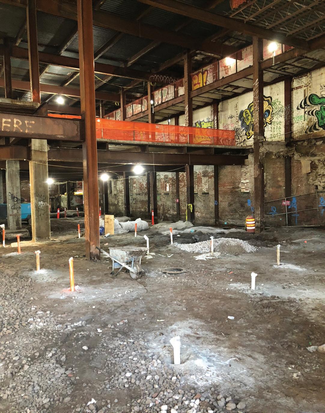
mated settlement under the proposed load. The load tests employed soil stockpiles to surcharge large areas and monitored movement of the mat using traditional optical survey. The type of fill used for the stockpiles was monitored to ensure general conformance with the assumed unit density, and consisted of silty sands commonly used as fill in the region.
Top of mat foundation settlements were continuously monitored by taking optical survey measurements using an automated motorized total station (AMTS). Survey prisms were mounted to the top of 3-inch diameter steel pipes bolted to the top of the mat. A 12-inch diameter PVC casing was centered on the steel pipes to minimize any disturbances caused by the soil placement. Soil was applied by mechanical means to a series of predetermined heights that corresponded to the increments of a typical pile load test schedule.
The measured settlement behavior for both Boiler House and Turbine Hall loads tests were judged to have been elastic throughout the test load application and correlated well with theoretical estimates. With these encouraging results from the load tests, the rest of the project construction could proceed.
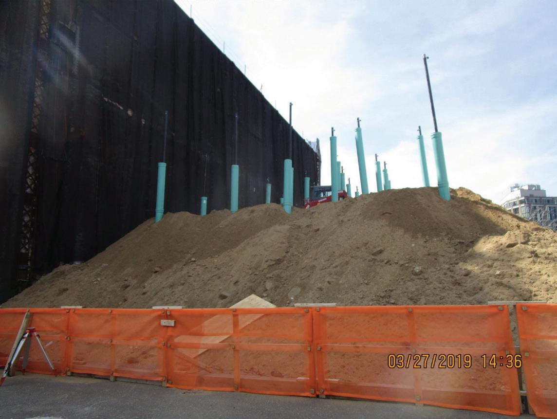
Conclusion
The project would not have been feasible without re-use of the historic abandoned foundations. Creative problem-solving, methodical engineering, collaboration between consultants and the authorities, and a supportive client, were the keys to success.■
Full references are included in the online version of the article at STRUCTUREmag.org
Eytan Solomon, P. E., LEED AP is a Senior Associate at Silman and a member of STRUCTURE’s Editorial Board. (eytan.solomon@silman.com)
Richard Lo, P. E. is a Senior Project Manager at Langan, where he has focused on geostructural interaction, geotechnical engineering, and waterfront structures. He currently leads geotechnical projects in Texas out of Langan’s Austin office. (rlo@langan.com)
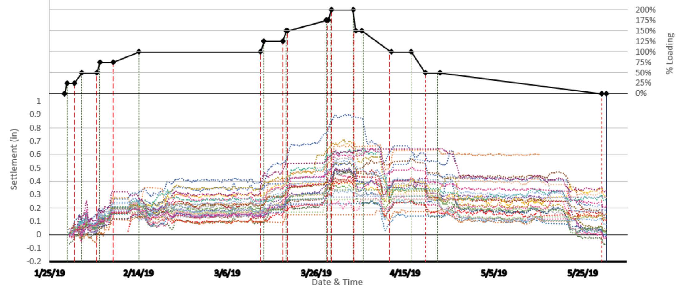
STRUCTURE magazine 46
-
Load history and settlement plot for the Boiler House load test.
Grout injection port holes. Photo courtesy of Silman.
Load test in progress. Photo courtesy Silman.
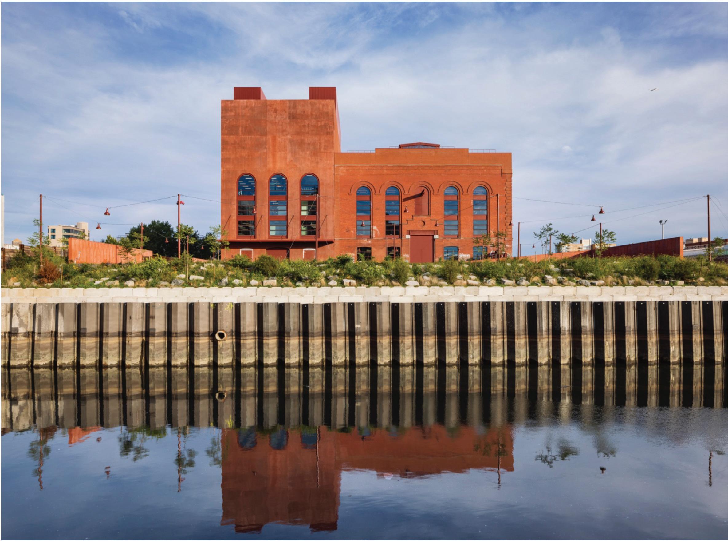

MARCH 2024 47
Load history and settlement plot for the Turbine Hall load test.
Completed project. Powerhouse Arts. Photo courtesy of Albert Vecerka/Esto
Behind the Scenes of Structural Engineering Reconnaissance Efforts
A team of structural engineers investigated the aftermath of the for the Mw 7.8 and M w 7.5 Türkiye (Turkey) Earthquakes of February 6, 2023.
By Robert K. Dowell, Gulen Ozkula, Jui-Liang Lin, Tunc Deniz Uludag, and Ayse Hortacsu
On February 6, 2023, back-to-back
M w 7.8 and M w 7.5 earthquakes struck southern Türkiye (Turkey). They caused complete collapse or significant damage to buildings, mosques, churches, industrial buildings, silos, and bridges. Worse, the collapse of tens of 1,000s of residential buildings killed at least 50,000 people. These coupled events caused widespread damage in southern Türkiye and northern Syria, resulting in the most severe earthquake disaster in Türkiye’s history and, potentially, one of the most devastating events globally in terms of substantial loss of life, the collapse and subsequent demolition of tens of thousands of buildings, displacement of a large population, and the significant financial burden. This caused severe disruption over the large area, affecting (1) people’s lives who lost their homes, (2) the economy, and (3) education, with a total of about 15 million people in the affected regions of southern Türkiye. The M w 7.8 earthquake is of similar size (moment magnitude) to the famous 1906 San Francisco earthquake and what the media and people in general often refer to as the future “Big One” in California, both on the San Andreas fault. This M w 7.8 earthquake is approximately equal to a magnitude 8.1 event on the old Richter scale.

This article focuses on the formation of our structural engineering reconnaissance team, who we are, what we did, what types of structures we investigated, where we traveled, who we talked to, and what was said. While this is not a technical article, we have published two technical reports, a technical journal paper, and a technical article documenting observed failed and damaged structures.
Undoubtedly, an event of such magnitude as the two earthquakes of February 6, 2023, in southern Türkiye would attract significant international attention, with in-depth investigations to comprehend the deficiencies observed in Türkiye and a reevaluation of both design codes and approaches, especially given that Türkiye has modern seismic design specifications comparable to those used in the United States and the West. In the aftermath of this earthquake disaster, conducting a comprehensive review of the existing design standards and practices is essential, focusing on identifying areas for improvement and implementing revised protocols. The international community recognizes the critical importance of collectively acquiring knowledge from this event, ensuring that invaluable insights are seamlessly incorporated into future design strategies to bolster seismic resilience and effectively mitigate the global impact of similar earthquakes. Consequently, local and international reconnaissance teams collaborated and shared information immediately after the incident, enabling the development of comprehensive reconnaissance action plans while ensuring a cohesive and coordinated approach without interrupting ongoing rescue operations.
Gulen Ozkula, our team leader, communicated effectively with Turkish government authorities with whom she had collaborated during the previous Izmir (Aegean Sea) earthquake reconnaissance in 2020. Gulen conducted email correspondence with the National Science Foundation (NSF) RAPID program to explore proposal options for the reconnaissance team. She also established contact with the highly-regarded seismic organizations of the Earthquake Engineering Research Institute (EERI) and the Structural Extreme Events Reconnaissance (StEER) network to foster collaboration and knowledge sharing in the field, which led to the publication of our reconnaissance report in the EERI Clearinghouse. This report is on the EERI Clearinghouse website. Note that this published report includes input from two reconnaissance teams: the core group of our structural engineering reconnaissance team and the geotechnical reconnaissance team, led by Tugce Baser, an Assistant Professor at the University of Illinois at Urbana-Champaign. Gulen established connections with local reconnaissance teams to obtain pertinent information from the field, allowing our team to determine priority areas that warranted visits and find the optimal timing for the U.S. team
STRUCTURE magazine 48
The sun setting over the Mediterranean Sea and Türkiye after the last day in the field.
to travel to the different hazard regions. This collaborative communication network facilitated informed decision-making and strategic planning for our reconnaissance efforts.
Structural Engineering Reconnaissance Team (Mountain Goats)
Due to the earthquake’s considerable magnitude and widespread impact in southern Türkiye, meticulous planning was imperative in determining the reconnaissance route, duration of the mission, and team composition. Considering her field experience and proficiency as a native speaker originally from Türkiye, Gulen Ozkula, an Assistant Professor at the University of Wisconsin, Platteville, assumed the role of coordinating the entire expedition and establishing local connections. With the reconnaissance route and duration finalized, a diverse team comprised of experts from various disciplines was assembled to ensure comprehensive coverage. In addition to team leader Ozkula, team members include Robert K. Dowell, a structural engineering professor at San Diego State University (SDSU) and Director of the SDSU Structural Engineering Laboratory; Tunc Deniz Uludag, a structural engineer at Martin/Martin Inc. in the U.S., and originally from Türkiye; Ayse Hortacsu, a structural engineer and Director of Projects at the Applied Technology Council (ATC) in the U.S., also originally from Türkiye; and Jui-Liang Lin who is a structural engineer and Research Fellow, as well as Division Director for the Building Engineering Division of the National Center for Research on Earthquake Engineering (NCREE) in Taiwan, another location that had a major and well-known earthquake from 1999.

two weeks after the two earthquakes, and met for the first time on the morning of the 20th for breakfast at the lobby of Hotel Ibis. This date was selected as the first day for the field because it was the day after search and rescue efforts were stopped and before most of the damaged and failed structures were demolished and removed, or changed in any way. Adana would be our base for the full time we were in southern Türkiye, leaving in the morning to the most affected areas and returning each evening.
Daily Routines to the Field and Back to Our Base in Adana
On the first day in the field, the team came upon the large Nurdagi Viaduct and parked to take a closer look without any prior notice that the bridge was damaged. Uludag was the first to see the plastic hinge formed part way up the large 10-footdiameter reinforced concrete (RC) column, resulting in Dowell and Uludag descending the long distance down to the bridge’s foundations. At the same time, the remaining team members stayed at the top of the structure, next to the adjacent roadway we came in on. Observing how Dowell and Uludag moved down the steep dirt embankments and jumped multiple obstacles to the bottom of the bridge, Hortacsu gave our team the name Mountain Goats, and it stuck! We were in the low mountains of southern Türkiye at the time, where the Nurdagi Viaduct is. On a subsequent trip to Türkiye, Dowell confirmed that all columns are being retrofitted with steel jackets at an in-person meeting in Ankara with the design engineer responsible for the seismic retrofit of this viaduct. He also met with engineers at the Turkish Highway Authority, including the Chief Bridge Engineer for Türkiye. Overall, the transportation network performed well and was fully operational within three days of the earthquakes. This is in stark contrast to the residential construction that suffered 1,000s of collapsed buildings and was responsible for most, if not all, of the deaths in this disaster.
The team arrived in Adana, southern Türkiye, on February 19,
Earthquake reconnaissance efforts presented considerable challenges. Assessing the aftermath of a major earthquake entails confronting the distressing realities of extensive devastation, loss of life, and human suffering. Furthermore, it involves enduring physically demanding conditions for long hours within a hazardous environment. Ongoing aftershocks, collapsed structures, and unstable ground amplify the risks reconnaissance teams face. Thus, meticulous coordination and careful planning were required before entering the affected zones. One example is wearing masks, which our team often did, not because of COVID-19, but to protect against breathing significant concrete dust and other hazardous materials from the ongoing demolition and removal work in the affected cities. Another considerable risk was driving into areas with multiple collapsed and damaged/leaning buildings, with the road width narrowed, and having to drive very close to and around unstable structures that could fall or topple further at any time, especially in an aftershock.
Given the profound devastation within the hazard zones and the long daily drives from Adana to the different regions of interest, securing a vehicle and driver was essential to facilitate the reconnaissance mission. This allowed our team the flexibility to stop at any time (even when no parking was available since the driver could drop us off, leave, and pick us up when we were done) and closely examine intriguing structures encountered along the
MARCH 2024 49
The recon team, “Mountain Goats,” (from left to right, Rob, Gulen, Ayse, Deniz, Jui-Liang) explored many sites, including that of the Nurdagi Viaduct on their first day in the field.

way, especially ones that we could see as we were driving along had fallen over or were severely damaged. With this capability, we could thoroughly investigate sites of interest to enhance our understanding of the earthquake’s impact. In the mornings, we would meet for breakfast at about 7 a.m. or 7:30 a.m. at the hotel lobby, then sit together to eat and talk before going up to our rooms to gather what we needed for the day in the field, then meet again outside the hotel in the van by about 8 a.m. Each day, we traveled to different affected cities or regions and returned in the evening, with drive times each way of between one and three hours. This went on for six days in a row. While looking at structures in the field only in sunlight, we often returned to Adana after dark due to the long drive times. We ate dinner together each evening in Adana.
Places Visited
The Mountain Goats visited structures in the most affected cities and regions in southern Türkiye, including Gaziantep, Iskenderun, Osmaniye, Antakya (Antioch), Kahramanmaras, Nurdagi, Golbasi, and Hatay. As the van approached a region that experienced severe shaking, we would typically start seeing damaged and collapsed structures out the window while still driving along in our van, such as farmhouses and various other structures in rural areas. Often, we would see something of interest and ask the driver to stop; then, we would all pile out of the van and walk toward the structure. We visited and looked over the structure for damage, sometimes with permission and other times without, depending on the situation and accessibility of the site. This happened most often with industrial facilities and silos that we could see had toppled. Part of this process was
to take a picture of the handheld Garmin GPS unit that Rob had on his belt, allowing us to figure out later where and what the structure was using the GPS coordinates since we were often stopped in—what felt like—the middle of nowhere.
Communication and Collaboration: Engaging With Locals and Working With Stakeholders
For international researchers, conducting reconnaissance efforts in foreign countries presents several challenges. Cultural and linguistic barriers may hinder communication and comprehension. Local knowledge, resources, and infrastructure constraints can compromise the precision and understanding of assessments. In addition to adapting to diverse institutional frameworks and safety concerns, it is necessary to build networks with local specialists and acquire permission to visit a site or structure, if required. Time constraints and coordination further complicate these endeavors, highlighting the need for proactive planning, collaboration, and cultural awareness to ensure the success of international reconnaissance missions. The Mountain Goats were fortunate to have Hortacsu, Uludag, and Ozkula, all originally from Türkiye and, therefore, native speakers with a deep understanding of the culture and many local connections to help our foreign researchers overcome these obstacles.
It was essential to collaborate with individuals from the local region to overcome the complexities of gaining relevant authorizations and obtaining exact instructions for specific sites. For instance, on the third day in the field, the team visited Ercan Acimis, a local business owner originally from Iskenderun. While at his office, we were served cups of tea while we talked and got
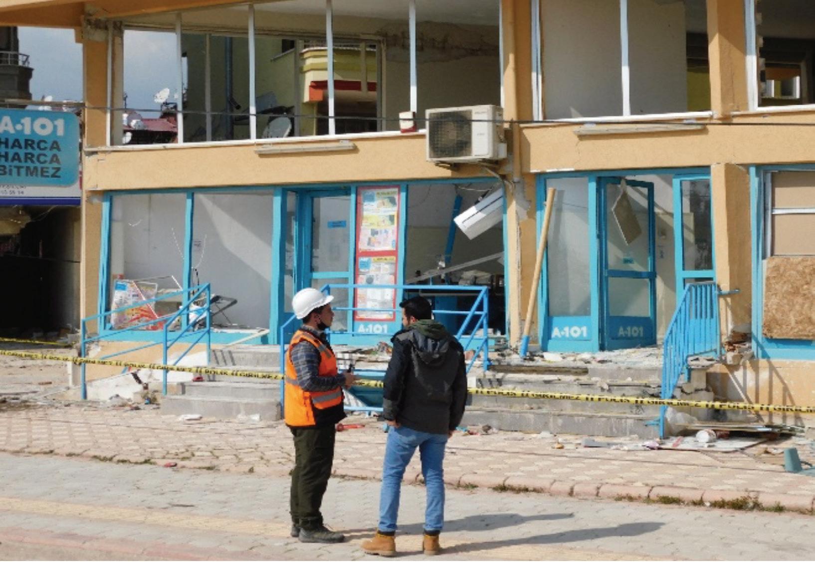
STRUCTURE magazine 50
Six days in the field in southern Türkiye, including day, locations, drive times each way, and drive distances each way. Image developed by team member, Tunc Deniz Uluda.
Team Member Deniz (left) and Ibrahim Baran.
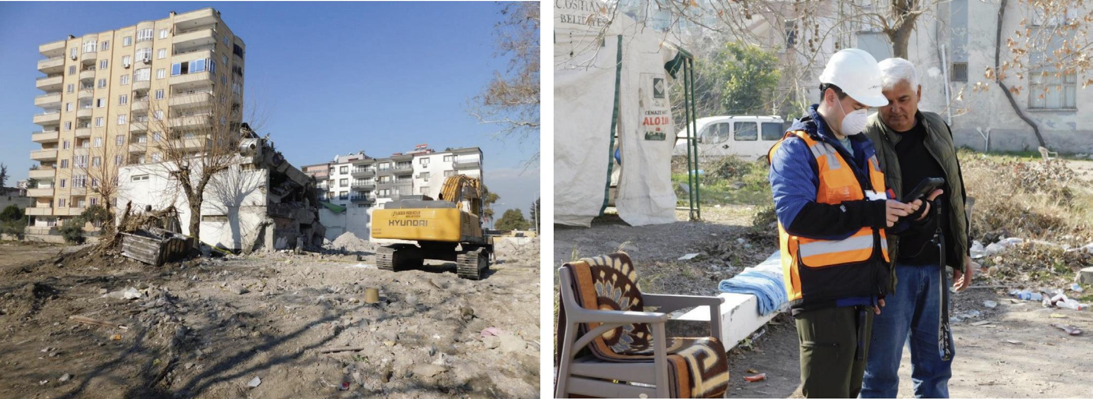
information. He told us about the damaged bridge over the Asi River, which became one of two main bridge structures with severe and unusual damage to the team, and other locations and potential structures of interest. He also called various people to get more information and permits based on our questions.
In Nurdagi, Turkish engineer Ibrahim Baran (with the Ministry of Environment and Urbanization), a friend of Uludag’s, came with us in our van, sitting in the front passenger seat to direct our driver where to go, showing us around parts of the city to see various damaged and failed buildings of interest, including some that had properly formed plastic hinges in the frame members. He was responsible for overseeing the demolition and removal of heavily damaged buildings tagged for demolition. As we were standing on the street looking at damaged buildings, a married couple walked up to talk to Baran about their home right next to a severely damaged building marked for demolition. They asked that he bring the building down without affecting their home, which was not damaged. He responded that he would try but could not promise anything.
On the first day in the field, Uludag and Dowell met Hasan, an excavator operator responsible for demolishing a collapsed building. He told us that 104 of the 107 residents of that building had died. Hasan also said that he helped bring the dead out of the building and that they were still on their mattresses, where they had perished from the just-after 4 a.m. earthquake.
Yakup, whose mother was killed in the earthquake, spent considerable time showing team members Uludag and Dowell around his damaged village where the fault rupture from the M w 7.8 earthquake had come through, with significant surface rupture, subsidence, and lateral spreading in many locations around the village, resulting in splitting one house right down the middle. This tour included walking into people’s homes, their backyards, and alleyways
around and through the village. Such access wouldn’t have been possible without Yakup, who was kind enough to spend much time with us and knew all the villagers. The local village people gave us tea, which was much appreciated.
During our reconnaissance tour, we were profoundly touched by the genuine hospitality exhibited by the Turkish people at every step. One team member, Jui-Liang Lin, received special attention and was treated with great reverence. The Turkish people strongly believe that Japanese engineers possess extensive expertise and experience in earthquake engineering, thus garnering immense respect for engineers of Asian descent. Consequently, residents whose homes had sustained varying degrees of damage at almost every location we visited expressed a strong desire for Jui-Liang Lin to conduct further investigations. At many stops, the locals wanted to take pictures with him, and he happily obliged them each time, never letting on that he was actually from Taiwan rather than Japan. Clearly, the input of every expert is invaluable for those significantly affected by this devastating event.
As fellow human beings, we researchers were all emotionally moved by witnessing the hardships faced by the local population and hearing the stories of their lost loved ones. Whenever individuals approached us seeking expert opinions, we endeavored to provide assistance and impart as much information as possible. We aimed to ensure that if their homes had suffered severe damage, they would refrain from reentering until it was deemed safe. It is important to note that unfortunate fatalities occurred due to aftershocks when some individuals ventured into their severely compromised buildings in an attempt to retrieve personal belongings.
As fellow human beings, we researchers were all emotionally moved by witnessing the hardships faced by the local population and hearing the stories of their lost loved ones. Whenever individuals approached us seeking expert opinions, we endeavored to provide assistance and impart as much information as possible.
Going Through the Largest Aftershock (Mw 6.3)
While in Adana, Southern Türkiye
At the end of the first day in the field, the Mountain Goats went to dinner for a classic kebab at a well-known restaurant in
51 MARCH 2024
Team Member Deniz (left) and Hasan.
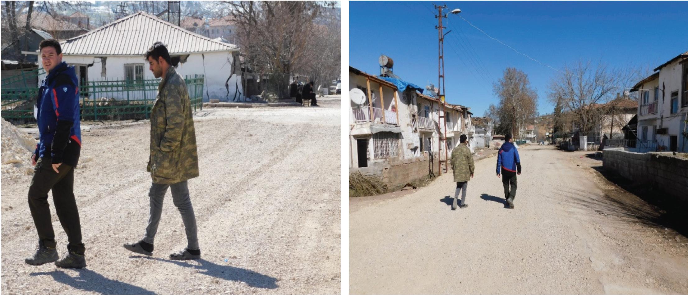
Adana called Onur Kebap. The Adana Kebab is known throughout Türkiye, being served in places as far away as Istanbul and in the capital, Ankara, as a specific type of kebab. Although we selected the town of Adana for its central location (distance) to the most heavily damaged cities and regions, while being far enough away where we felt safe from building collapse due to further earthquakes and aftershocks, Adana did suffer more than ten building collapses on February 6 from the large back-to-back earthquakes. When the appetizers were done, and right after the waiter placed Dowell’s first kebab in Türkiye on the table before him, but before his first bite, the two-story building started swaying back and forth from an earthquake. The servers and restaurant staff all had the same shocked look on their faces, pure terror with wide-open eyes, and then they ran for the exit and down the stairs to the safety of the outside, with the rest of us following. They were all suffering from severe trauma due to what they had gone through on February 6, only two weeks earlier.
After the shaking had ended and a few minutes more spent outside, we all made our way back up to the restaurant, where we finished our meals. After messages from family and friends, we turned on the restaurant TV, and learned from national and international news that we had just experienced an M w 6.3 aftershock, the single largest aftershock of the 1,000s since the big earthquake. Note that this has also been reported as its own earthquake, since it occurred on a different fault than the two earthquakes of February 6. There was also a panicked series of messages from SDSU about Dowell’s well-being, finally relayed back and forth through his daughter, Sophia, that he went through the big aftershock but was all right. Sadly, it collapsed several more buildings in Hatay, killing a few more people there, which was the location of the epicenter. The shaking we felt in Adana was less severe than
in Hatay since we were about 70 miles away. When we returned to Hotel Ibis after dinner, people were still milling outside, afraid to go back into the eight-story building after the shaking; the motion was probably significantly amplified over what we felt at the restaurant due to the hotel’s height.
Lessons Learned From the Earthquake Reconnaissance
The extensive damage caused by the two earthquakes of February 6, 2023, resulted in the worst earthquake disaster in Türkiye’s history, with over 50,000 people killed and tens of 1,000s of buildings collapsed or damaged beyond repair. It also left millions homeless, resulting in multiple tent cities across southern Türkiye and over 300,000 destroyed apartments, indicating that the actual death toll may be much higher than the official number of 50,000, which was based on the number of bodies pulled from the rubble of collapsed buildings.
Our team anticipates that international collaboration and research engagement will catalyze advancing seismic design and construction practices in Türkiye.
The Türkiye reconnaissance trip allowed us to observe the extent and type of damage caused by the earthquake. Comprising engineering experts in bridge structures and building structures of reinforced concrete and steel, each team member had the opportunity to acquire firsthand knowledge from this devastating seismic event and collect perishable data for potential future proposals to enhance design codes. Furthermore, our engagement with the local community allowed us to gain profound insights into their experiences during the earthquake, encompassing a comprehensive understanding of evacuation procedures, the efficacy of emergency response measures, and the resilience demonstrated by communities in the face of such devastating disasters.
STRUCTURE magazine 52
Team Member Deniz (blue jacket) and local village resident Yakup.
Our team anticipates that international collaboration and research engagement will catalyze advancing seismic design and construction practices in Türkiye. We hope that through this collective effort, we will not only derive valuable insights from this event but also foster the development of resilient structures and communities globally. By leveraging the knowledge gained from studying this earthquake, we hope the civil engineering community will contribute to creating safer and more resilient built environments worldwide. ■
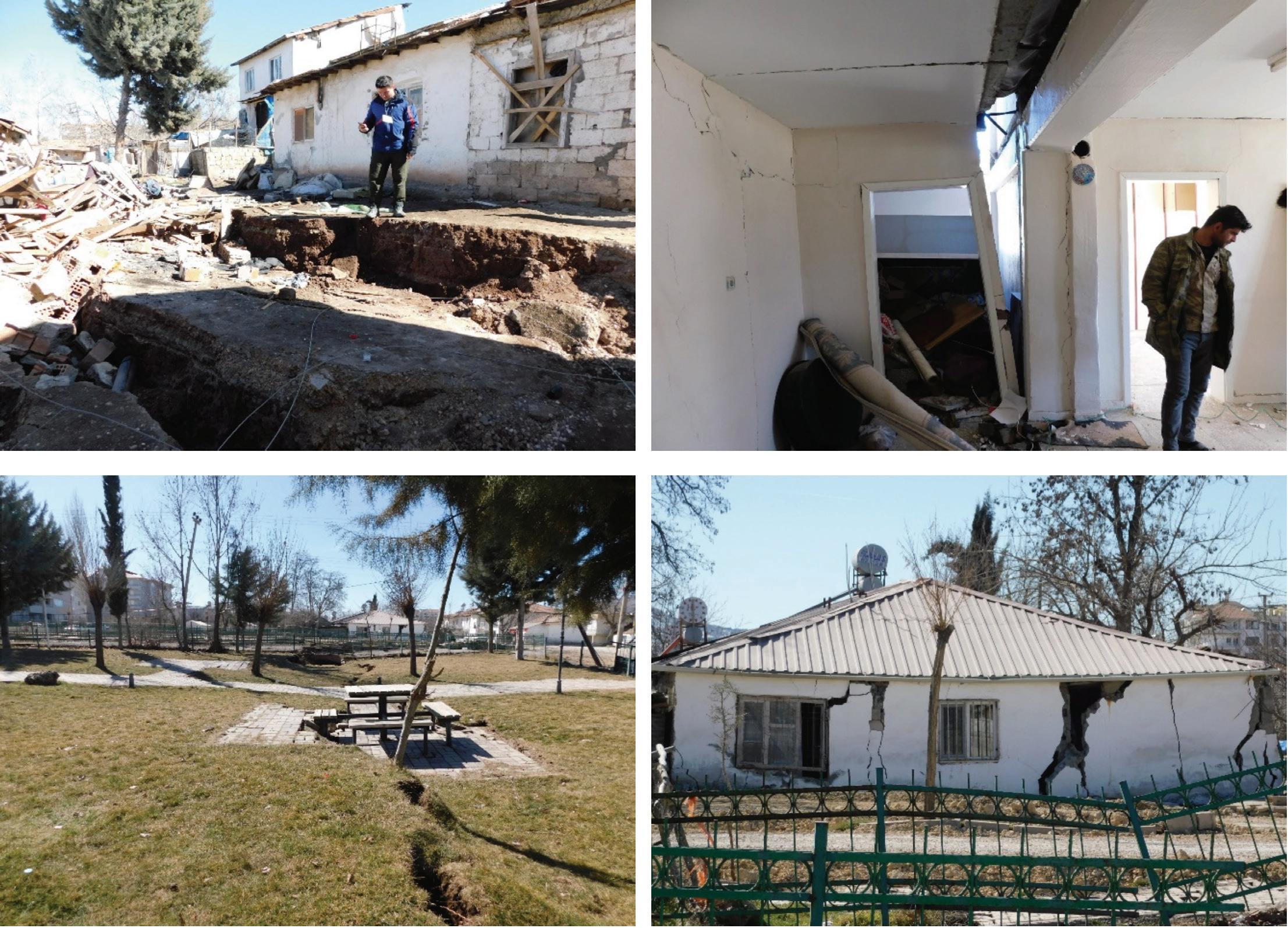
Full references are included in the online version of the article at STRUCTUREmag.org .
Prof. Robert K. Dowell, Ph. D., P. E., is Associate Professor of Structural Engineering and Director of the Structural Engineering Laboratory at San Diego State University (SDSU). He has over 30 years of experience in bridge design, structural analysis and physical testing to failure in the laboratory. He can be reached at (rdowell@ sdsu.edu).

RECORDS
Eliminate the hassle of resubmitting your College transcripts
Exams results
Employment verifications
Professional references each time you apply for licensure in an additional state.
MARCH 2024 53
Damage in Yakup’s village from the fault rupture of the Mw 7.8 earthquake.
Build your NCEES Record today. ncees.org/records

A New Hope for Housing
Tall mass timber shows its potential in 1510 Webster Street.
By Jeff Brink and Michael Bauer
Three blocks from the construction site, the DCI Engineers’ Project Manager for the 1510 Webster Street development heard an airhorn blow from his home. The sound indicated that another mass timber panel was about to fly on his Oakland, California, residential project. It was the sound of progress because, by the time the PM walked to the site 15 minutes later, there was already a few thousand square feet of Mass Plywood Panel (MPP) deck in place.
Topped out in early August 2023, 1510 Webster Street, a 19-story residential tower with 17 stories of mass timber, is the first Type IV-A high-rise mass timber tower in the United States. In addition to being the tallest mass timber tower on the West Coast, 1510 Webster is also the first point-supported (beamless) MPP high-rise in the world.
DCI Engineers, the Structural Engineer of Record (SER) for the project, collaborated with oWOW, an Oakland-based developer, architect, and general contractor, focusing on bringing more affordable housing options to the market through its vertically integrated mass timber project delivery system.
Mass timber has frequently been praised for its ability to provide greater speed of construction, though it has been difficult for many developers, designers, and construction teams to achieve.
oWOW’s vision and commitment to pursue a mass timber solution for 1510 Webster Street was paramount to the project’s success. oWOW committed to constructing the development from mass timber before the code adoption of the material, as they understood the advan tages it offered in terms of constructability and labor cost savings. In
Design Team
• Developer, Architect, General Contractor:
• Structural Engineer: DCI Engineers
• Mass Timber Installer: Webcor Timber
• MPP Manufacturer: Freres Engineered Wood
• Civil Engineer: Calichi Design Group
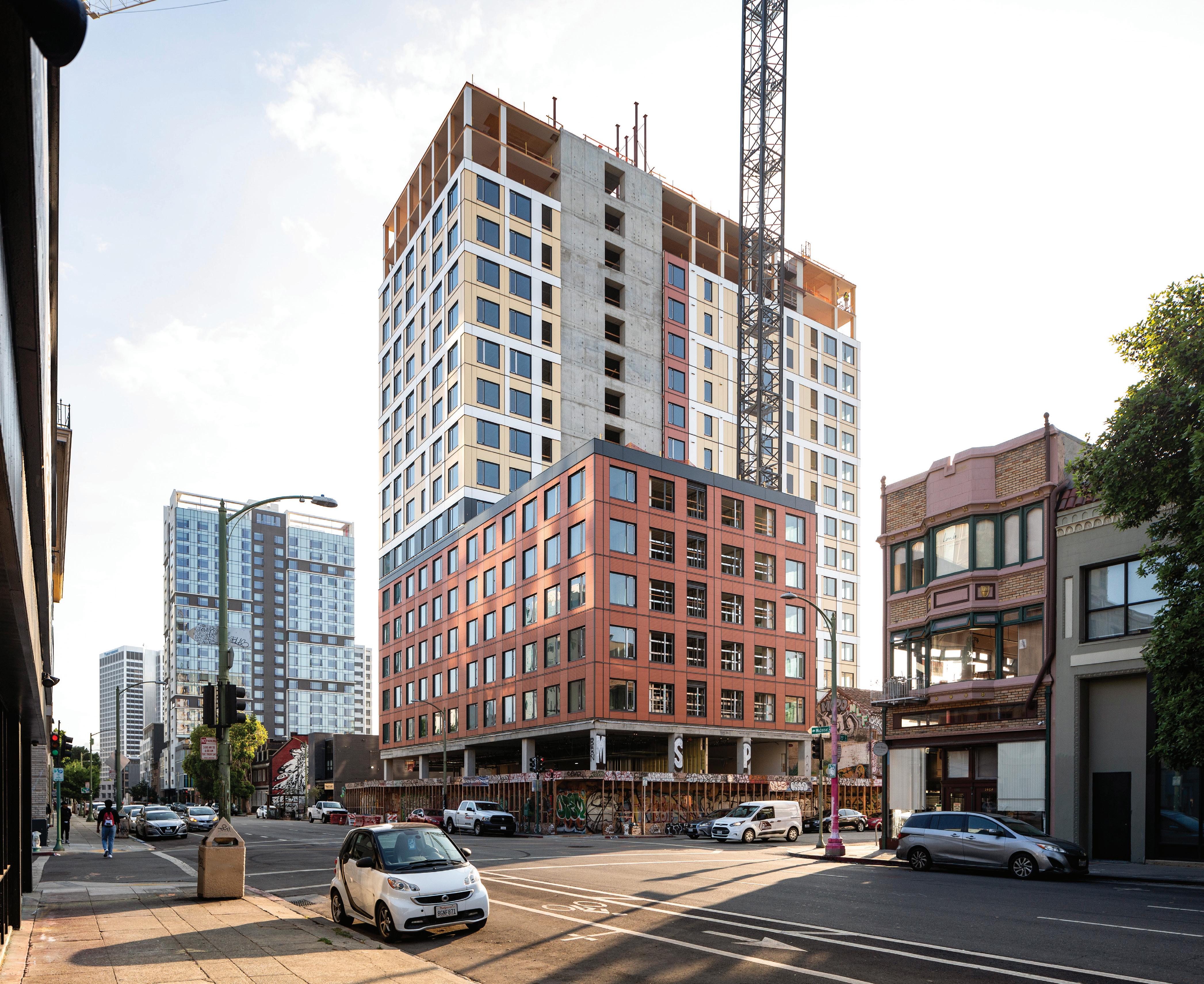
STRUCTURE magazine 54
 Photo by Andrew Nelson
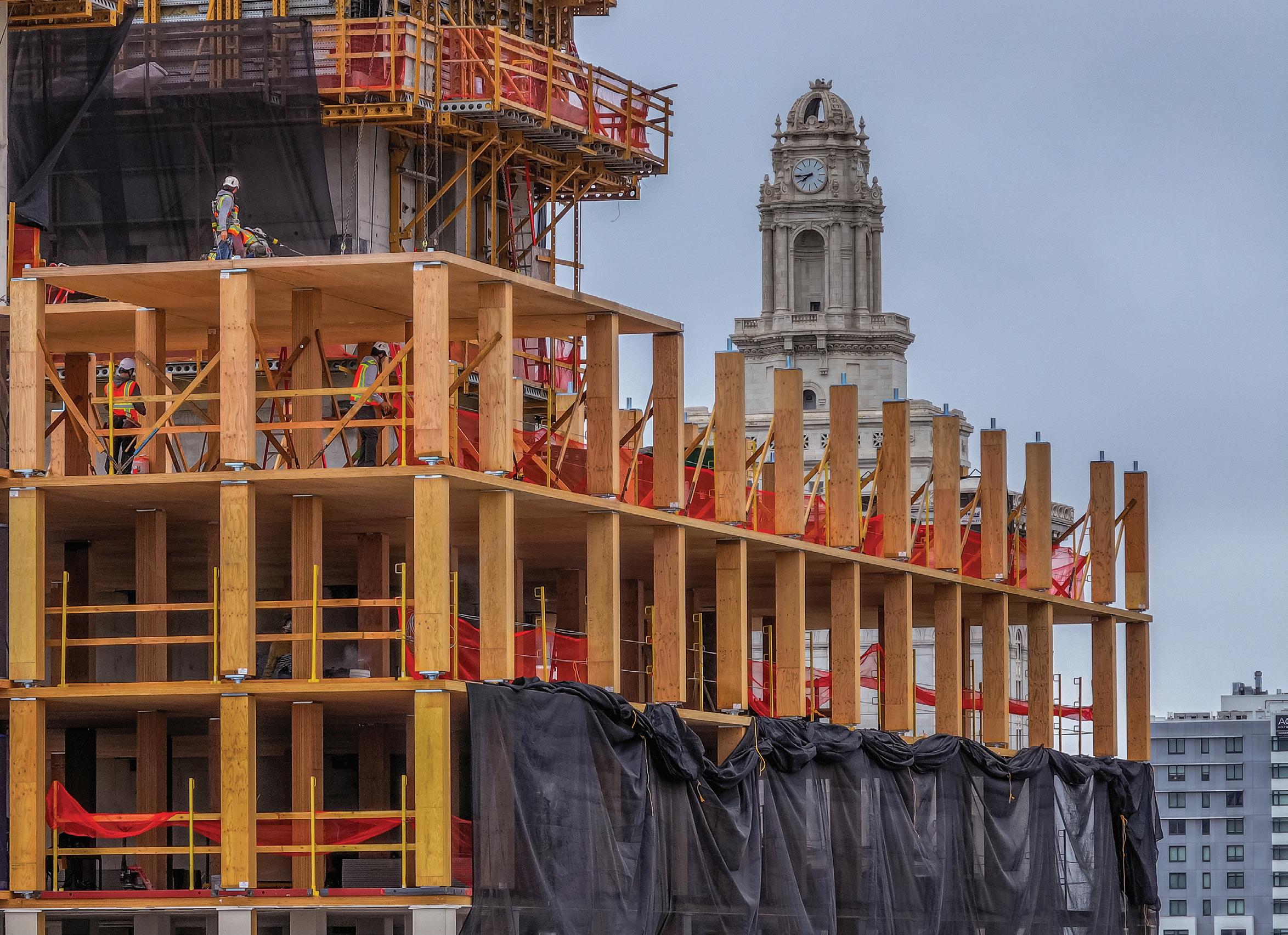
conjunction, oWOW and DCI spent over a year studying options to maximize every aspect of the building’s design and construction process. This effort included performing supplemental testing on the mass timber materials, studying multiple seismic force-resisting systems, evaluating mass timber framing solutions, and working endlessly to ensure the evaluation of each option incorporated initial cost, speed of construction, and secondary impacts. The result of this commitment to mass timber and the exhaustive evolution, testing, and analysis process is a first-of-its-kind high-rise residential building that will deliver rental housing at between 80% and 120% of the Average Median Income (AMI).
Mass Plywood Panels (MPPs)
To optimize the MPP floors, oWOW, DCI, and the MPP manufacturer, Freres Engineered Wood teamed up to develop and perform additional strength and deflection testing of the material. The MPP floors are comprised of multiple layers of plywood sheathing, which vary from 5 inches to 7 inches thick. Unlike more traditional mass timber panels such as cross-laminated timber (CLT), which uses perpendicularly orientated layers (lamella) of dimensional lumber such as 2x6’s, MPP provides higher flexural and shear strength, as
well as greater stiffness. The MPP's improved properties result from its construction, which utilizes the same techniques as traditional plywood but at a much thicker scale. However, DCI developed a testing protocol for the material because the actual limits of the MPP’s strength and stiffness were not definitively understood. Multiple tests were then performed, demonstrating MPP’s substantial capabilities and yielding a nearly 20% increase in allowable column spacing. This increased column spacing resulted in greater architectural and unit layout flexibility and reduced construction cost and schedule.
1510 Webster also utilized Mass Ply Lam (MPL) for the columns that support the MPP floors. MPL is very similar to MPP in that it is fabricated from a thick build-up of plywood. The MPL columns are spliced at each floor to eliminate any vertical load transfer through the MPP. DCI worked with the Italian-based firm Rothoblaas, which provides point-supported connections for mass timber projects around the globe. As part of the MPP testing, DCI and the team were able to confirm that the punching shear capacity of the MPP is indeed significantly higher than previously anticipated. As a result, the amount of material in the steel column splice connections was able to be optimized and substantially reduced, with steel plate thicknesses varying from 1 inch at the top floors up to 2 inches at the lower floors. Integration and optimization of the Rothoblaas Pillar connections also allowed the mass timber sub-contractor,
STRUCTURE magazine 56
1510 Webster Street rises 19 stories, 17 of which are constructed of mass timber. Photo by Erin Spaulding, DCI
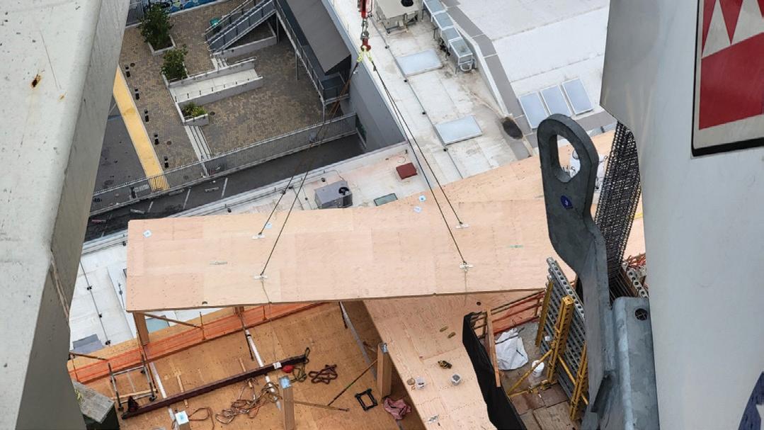

Webcor Timber, to achieve an install time of approximately four minutes per column.
Reducing Mass Increases Benefits
Since 1510 Webster Street is located just over three miles from the Hayward fault and 14 miles from the San Andreas fault, one of the highest seismic regions in the world, mass timber’s substantial reduction in weight provided a great advantage. Reducing weight is critical for improving a building’s seismic response. More specifically, the MPP floors and columns allowed the Webster Street project to be up to 40% lighter than a cast-in-place concrete system. The more lightweight floor system subsequently reduces demands on the lateral system and, thereby, the foundations, equating to a reduction in materials.
A concrete shear wall system was selected to stabilize the building against seismic and wind forces. As previously noted, DCI and oWOW studied multiple seismic force-resisting systems, and the concrete shear wall system proved the most cost-effective. Some of the concrete shear wall benefits included better sequencing with the mass timber installation and minimization of field welding. As the SER on the project, DCI Engineers optimized the concrete shear walls by integrating high-strength reinforcement into the design. The high-strength reinforcement, combined with the reduced demands from the mass timber, made for an incredibly efficient system, which could be cycled in just three days by the concrete sub-contractor, Webcor Concrete.
The introduction of mass timber into the North American market has been extremely beneficial in helping to reduce the carbon impact of buildings. A peer-reviewed whitepaper published in 2021 by Sustainability & MDPI, "Comparative LCAs of Conventional and Mass Timber Buildings in Regions with Potential for Mass Timber Penetration," measured the embodied carbon associated with 8, 12, and 18-story buildings utilizing mass timber and concrete construction in the Pacific Northwest, Northeast, and Southeast regions in the United States.
The study showed the mass timber buildings exhibited a reduc tion in the embodied carbon varying between 22% and 50% compared to the concrete buildings over all regions and building heights. As discussed, the reduced structural mass of the mass timber building gravity system allows for substantial reduc tions in all other building materials. In particular, minimizing concrete and steel within shear walls, foundations, and columns means the sustainability benefits are magnified throughout the
building. As of publication, DCI was performing a comparative Whole Building Life Cycle Assessment (WBLCA) case study, in collaboration with WoodWorks, to confirm and quantify the embodied carbon reductions of mass timber versus a conventional concrete structure.
CORE-Bel Custom Connection
One of the most significant challenges with the 1510 Webster Street design was detailing the mass timber seismic and gravity connections to accommodate the larger tolerances of the castin-place concrete shear wall construction. The MPP and MPL elements produced by Freres were prefabricated in their facility by a Computerized Numerical Control (CNC) machine. The CNC process meant every mass timber element was delivered to the site with a one-sixteenth inch tolerance. Construction of the concrete shear walls met all American Concrete Institute (ACI) tolerances, which are larger. This difference in construction tolerances can be compounded by variability setting reinforcing,
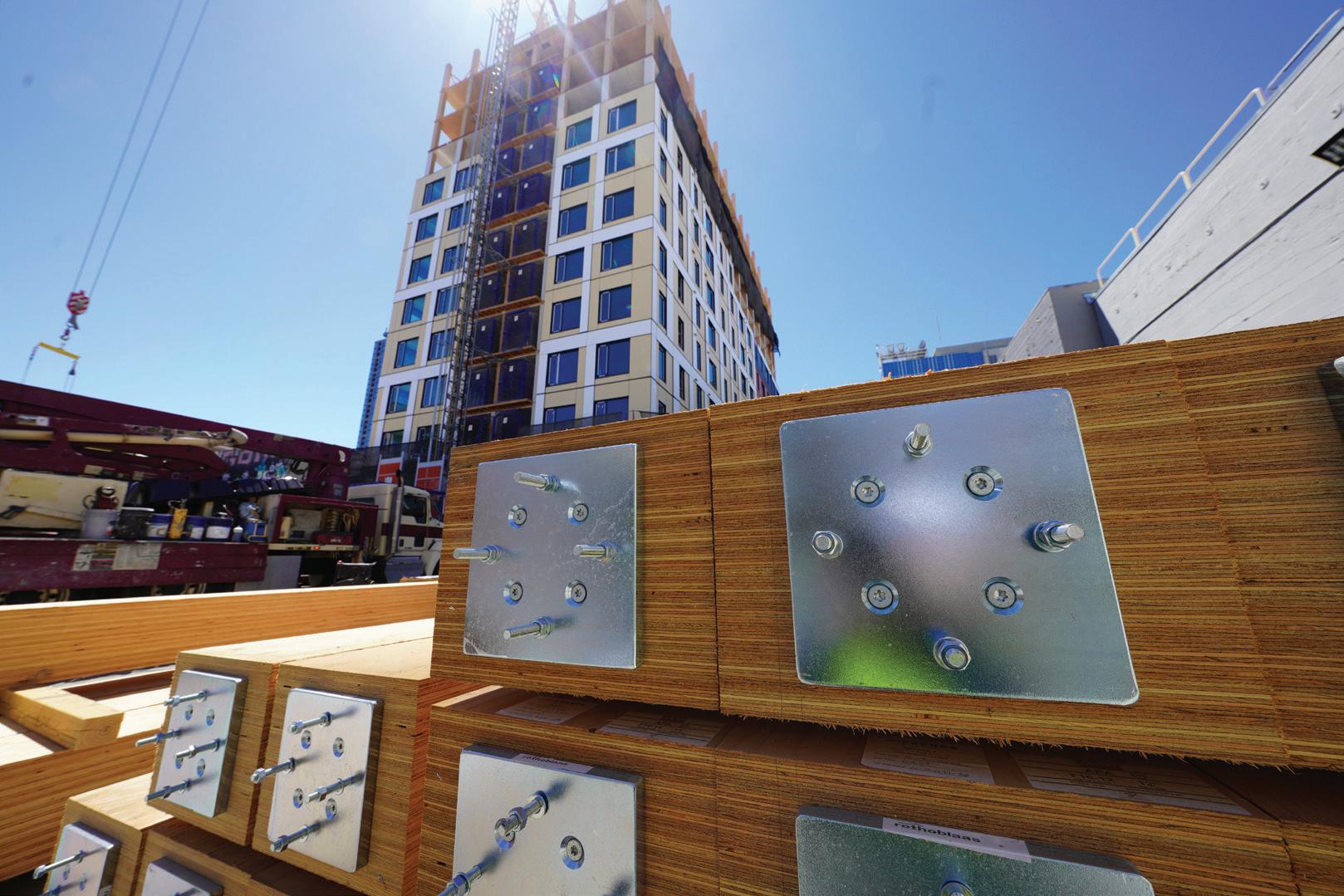
MARCH 2024 57
A 500-sf mass plywood panel is craned into place at 1510 Webster Street. Photo by Jeff Brink.
1510 Webster Street utilizes a custom CORE-bel connection, a combined gravity and seismic connection that reduced embeds. Photo by Erin Spaulding, DCI.
Rothoblaas' custom Pillar connection offers substantial opportunity for field adjustments.
particularly steel embeds, within the concrete forms. Therefore, every connection between the mass timber and concrete had to account for this variance. As a result of all these challenges, the DCI team set out to find an entirely different approach and provide a robust system that solves the problem while increasing the lateral load capacity.
Part of this solution included DCI’s custom CORE-bel connection, which offers substantial opportunity for field adjustments. While the vertical and horizontal locations can be field-measured to fit, the connection is designed for up to 2 inches of tolerance, both inplane and out-of-plane from the wall surface. The team found that these customized connections also reduced the required number of embeds by more than 40% compared to a more traditional continuous support angle approach.
The custom CORE-bel connection also maintains the purely point-supported philosophy for the structure, thereby avoiding beams or other continuous support elements. This is yet another way the 1510 Webster Street design is a first of its kind.
Looking to the Future
When DCI Engineers’ Project Manager for 1510 Webster Street completed his site visit around noon, an entire floor of MPP framing had already been set, and the construction team was
beginning work on the next level of MPL columns, a sequence that allowed for a reduction of more than one month on the constructure schedule. That rapid construction pace, combined with mass timber’s propensity for prefabrication, reduced mass, and minimal carbon footprint, made it the ideal solution for the Webster Street development. Since their initial collaboration on 1510 Webster, oWOW and DCI have started working through designs for more Type IV residential projects around the Bay Area. Those developments include a Type IV-B building in San Francisco and a Type IV-C in Oakland, scheduled to start construction in 2024. With each project, the team seeks out more ways to optimize MPP, taking advantage of its unique structural characteristics. As an industry, we are just beginning to realize the potential for mass timber to continue revolutionizing our built environment while minimizing the impact on our environment. ■
Jeff Brink is CEO and Principal of DCI Engineers. Based in the firm’s San Francisco office, Jeff has spearheaded multiple mass timber projects in California, including the state’s first multi-story mass timber building, 1 De Haro.
Michael Bauer is a Project Manager in DCI Engineers’ San Francisco office, specializing in high-rise construction and seismic design solutions for the Bay Area.
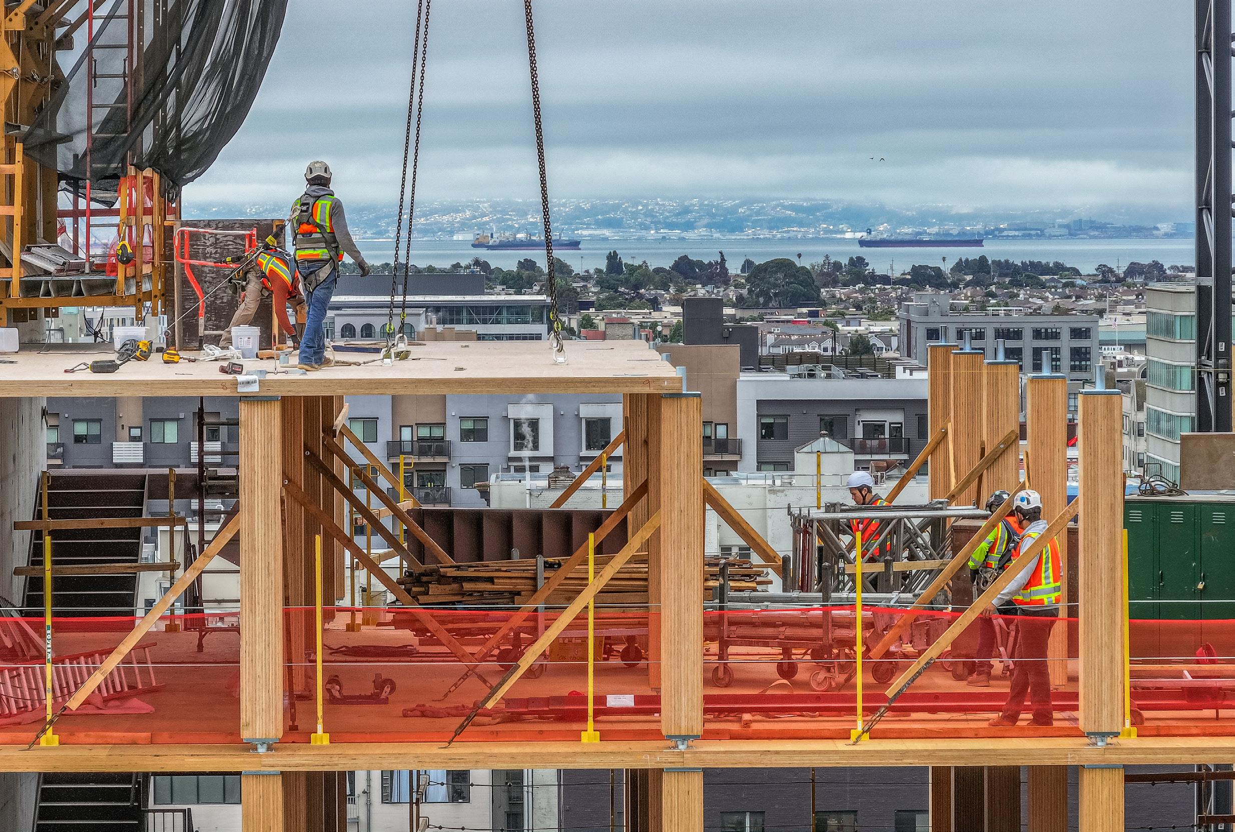
STRUCTURE magazine 58
Mass plywood panel (MPP) floors are comprised of multiple layers of plywood sheathing. MPP provides high flexural and shear strength, as well as stiffness. Photo by Erin Spaulding, DCI
UPDATES
2024 IBC Significant Structural Changes
Risk Categories (IBC Chapter 16)—Part 5.
By John “Buddy” Showalter, P. E., M. ASCE, M. NCSEA, and Sandra Hyde P. E., M. ASCE, M. NCSEA
Note: This multi-part series includes a discussion of significant structural changes to the 2024 International Building Code (IBC) by the International Code Council (ICC). Parts 1, 2, 3, and 4 ran in the November 2023, December 2023, January 2024, and February 2024 issues. Part 5 includes an overview of changes to IBC Chapter 16 on risk categories.
This multi-part series discusses significant structural changes to the 2024 International Building Code (IBC) by the International Code Council (ICC). Part 5 includes an overview of changes to IBC Chapter 16 regarding risk categories. Only a portion of the chapter’s total number of code changes is discussed in this article. More information on the code changes can be found in the 2024 Significant Changes to the International Building Code available from ICC (Figure 1).
snow load and ice thickness hazard maps incorporate consideration of less probable loads for structures assigned to higher risk categories, Importance Factors for those loads are no longer needed. However, the system reliabilities for earthquake are different from those for other environmental hazards because the design philosophy of ASCE 7 is to prevent system collapse in a risk-targeted maximum considered earthquake. Accordingly, ASCE 7 Table 1.5-2 which lists importance factors based on risk category was revised as follows:
ASCE 7-22
ASCE/SEI 7-22 Minimum Design Loads and Associated Criteria for Buildings and Other Structures includes provisions for risk categories and corresponding importance factors in Tables 1.5-1 and 1.5-2 respectively. However, IBC Table 1604.5 provides more comprehensive coverage of buildings assigned to various risk categories. The ASCE 7 Commentary provides background for the disparity. “The reason for this generalization is that the acceptable risk for a building or structure is an issue of public policy rather than purely a technical one…Individual communities can alter these lists when they adopt local codes based on the model code, and individual owners or operators can elect to design individual buildings to higher occupancy categories based on personal risk management decisions…[this] also provides individual communities and development teams the flexibility to interpret acceptable risk for individual projects.”
While wind and seismic loads have for some time been based on the risk category of the building, changes in ASCE 7-22 to snow, ice, and rain loads along with new provisions for tornado loads use the building’s risk category as well to determine load magnitudes (see Part 6 of this series in the April 2024 issue of STRUCTURE for more details).
According to the ASCE 7-22 Commentary, prior to ASCE 7-22, Importance Factors were presented for snow, ice thickness, and seismic loads for the four risk categories identified. The specific Importance Factors differed according to statistical characteristics of the environmental loads and the way a structure responds to those loads. Now that

IBC Risk Category Revisions
IBC Section 1604.5 and IBC Table 1604.5 provide a joint presentation of the risk categories of buildings and other structures. The risk category (RC) reflects the relative seriousness of potential failure. Categories vary from the lowest hazard to human life (RC I) to the highest hazard (RC IV) and serve as a threshold for a variety of code provisions related to earthquake, rain, flood, snow, ice, tornado, and wind loads. Loads increase with the importance of the facility. The result is a more robust structure that would be less likely to sustain damage under the same conditions than a structure assigned to a lower risk category. The intent is to enhance a structure's performance based on its use or the need to remain in operation during and after a design event.
In the 2024 IBC, most parking garages are assigned to RC II, a multiple occupancy
MARCH 2024 59
code
Figure 1. More information on the code changes can be found in the 2024 Significant Changes to the IBC available from the International Code Council.
Risk Category from Table 1.5-1 Snow, I s Ice Thickness, Ii Ice Wind, Iw Seismic, I e I 0.80 0.80 1.00 1.00 II 1.00 1.00 1.00 1.00 III 1.10 1.15 1.00 1.25 IV 1.20 1.25 1.00 1.50
ASCE 7-22 Table 1.5-2 Importance Factors by Risk Category of Buildings and Other Structures for Snow, Ice, and Earthquake Loads [Courtesy American Society of Civil Engineers (ASCE)]
trigger was added for RC IV, power-generating stations are separated into RC III or IV based on power unit ratings, and photovoltaic (PV) panel systems are clarified for all four risk categories. New to RC IV are public utility facilities providing power generation, potable water treatment, or wastewater treatment. All Group I-2 occupancies and most of Group I-3 occupancies are also moved to Risk Category IV.
1604.5 Risk category. Each building and structure shall be assigned a risk category in accordance with Table 1604.5. Where a referenced standard specifies an occupancy category, the risk category shall not be taken as lower than the occupancy category specified therein. Where a referenced standard specifies that the assignment of a risk category be in accordance with ASCE 7, Table 1.5-1, Table 1604.5 shall be used in lieu of ASCE 7, Table 1.5-1.
Exceptions:
1. The assignment of buildings and structures to Tsunami Risk Categories III and IV is permitted to be in accordance with Section 6.4 of ASCE 7.
2. Freestanding parking garages not used for the storage of emergency services vehicles or not providing means of egress for buildings or structures assigned to a higher risk category, shall be assigned to Risk Category II.
Risk Category
Nature of Occupancy
III Buildings and other structures that represent a substantial hazard to human life in the event of failure, including but not limited to:
• Group I-2, Condition 1 occupancies with 50 or more care recipients.
• Group I-2, Condition 2 occupancies not having emergency surgery or emergency treatment facilities.
• Group I-3, Condition 1 occupancies.
• Any other occupancy with an occupant load greater than 5,000.a
• Power-generating stations with individual power units rated 75 MWAC (megawatts, alternating current) or greater, water treatment facilities for potable water, wastewater treatment facilities and other public utility facilities not included in Risk Category IV.
IV Buildings and other structures designated as essential facilities and buildings where loss of function represents a substantial hazard to occupants or users, including but not limited to:
• Group I-2 occupancies, Condition 2 occupancies having emergency surgery or emergency treatment facilities.
• Group I-3 occupancies other than Condition 1.
• Public utility facilities providing power generation, potable water treatment, or wastewater treatment.
a. For purposes of occupant load calculation, occupancies required by Table 1004.5 to use gross floor area calculations shall be permitted to use net floor areas to determine the total occupant load. The floor area for vehicular drive aisles shall be permitted to be excluded in the determination of net floor area in parking garages.
1604.5.1 Multiple occupancies. Where a building or structure is occupied by two or more occupancies not included in the same risk category, it shall be assigned the classification of the highest risk category corresponding to the various occupancies. Where buildings or structures have two or more portions that are structurally separated, each portion shall be separately classified. Where a separated portion of a building or structure provides required access to, required egress from or shares life safety components systems, designated seismic systems, emergency power systems, or emergency and egress lighting systems with another portion having a higher risk category, or provides required electrical, communications, mechanical, plumbing, or conveying support to another portion assigned to Risk Category IV, both portions shall be assigned to the higher risk category.
(No changes to Section 1604.5.1 Exception)
1604.5.2 Photovoltaic (PV) panel systems. Photovoltaic (PV) panel systems and elevated PV support structures shall be assigned to a risk category as follows:
1. Ground-mounted PV panel systems serving only Group R-3 buildings shall be assigned to Risk Category I.
2. Ground-mounted PV panel systems other than those described in items 1 and 5 shall be assigned to Risk Category II.
3. Elevated PV support structures other than those described in Items 4, 5, and 6 shall be assigned to Risk Category II.
4. Rooftop-mounted PV panel systems and elevated PV support structures installed on top of buildings shall be assigned to the same risk category as the risk category of the building on which they are mounted.
5. PV panel systems and elevated PV support structures paired with energy storage systems (ESS) and serving as a dedicated, stand-alone source of backup power for Risk Category IV buildings shall be assigned to Risk Category IV.
6. Elevated PV support structures where the usable space underneath is used for parking of emergency vehicles shall be assigned to Risk Category IV.
Change Significance:
Parking Structures
The new exception to IBC Section 1604.5 addresses an anomaly whereby large parking structures that serve airports, shopping centers, and other large buildings potentially triggered a RC III designation when floor areas exceeded 1 million square feet based on the parking garage occupant load factor. IBC Table 1604.5 designates “Any other occupancy with an occupant load greater than 5,000” as an RC III structure. The occupant load factor for parking garages is 200 gross square feet per occupant per IBC Table 1004.5. There are circumstances where even when deducting drive aisles and the other non-usable space to establish an occupant load based on the net area that the total occupant load can still exceed 5,000. The occupancy for parking garages is classified as a Group S-2 light hazard storage area and the occupant load density tends to be low due to the intermittent nature of the storage occupancy. It is unlikely that a large parking garage will have 5,000 occupants simultaneously entering or exiting a garage concurrent with a significant natural hazard event. Therefore, the new Exception 2 allows all parking garages to be assigned to RC II unless the building is used for emergency vehicles or is part of an egress path from a RC III or IV building – a highly unlikely design approach.
STRUCTURE magazine 60
IBC Table 1604.5 Risk Category of Buildings and Other Structures (only new or modified sections shown for brevity)
The modification to IBC Table 1604.5 footnote “a” clarifies that floor area for drive aisles in parking garages can be deducted when determining net floor area for the assignment of risk category. While occupants use drive aisles to access parked motor vehicles, they are not commonly identified as “aisles” based on the IBC definition (associated with the path of egress). Unlike mechanical access parking garages, vehicular aisles are an integral part of a garage’s function, and motor vehicle occupants are not concurrently located within the drive aisle.
Multiple Occupancies
In IBC Section 1604.5.1, the phrase “electrical, communications, mechanical, plumbing, or conveying” refers to the requirements of IBC Chapters 27 through 30, respectively. The references are intended to be generic, just like the provision’s references to undefined “life-safety systems” and to egress, access, and structural separation. As with many IBC provisions, it is appropriate to leave project-specific details to the project team with approval by the code official, in this case, to determine which aspects of those systems must function post-disaster for the RC IV building or utility.
Power-generating Stations
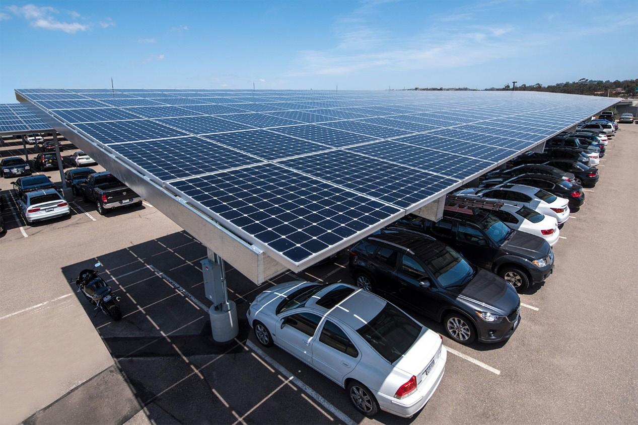
PV systems help clarify risk category assignments. A groundmounted PV system is defined as an independent system without useable space underneath, installed directly on the ground. An elevated PV system is defined as an independent PV panel support structure designed with useable space underneath, a minimum clear height of 7.5 feet, and intended for secondary uses such as providing shade or parking for motor vehicles.
Since there is no definition in the IBC for “power-generating stations” a modification was made to IBC Table 1604.5 to define the power generation threshold for categorization as a RC III structure. Note that 75 MWAC is established as the smallest power-producing unit of a power-generating station in North American Electric Reliability Corporation (NERC) Docket No. RR15-4-000, Order on Electric Reliability Organization Risk Based Registration Initiative and Requiring Compliance Filing (issued March 19, 2015). Therefore, power generation under the 75 MWAC limit does not trigger a Risk Category III or IV assignment.
Public Utilities
New to RC IV are public utility facilities providing power generation, potable water treatment, or wastewater treatment. Instead of drawing a line between normal operations and emergency backup, this change makes the distinction between public utilities (typically designated by a state or local commission) and other utilities such as communications or public transit. The discussion of Institutional Facilities also addresses public utilities and changes to the Risk Category IV designation.
Photovoltaic Panel Systems
New IBC Section 1604.5.2 resolves confusion about the assignment of risk categories for PV projects. Two new definitions for
Ground-mounted PV panel systems meet the description of RC I, as they “represent a low hazard to human life in the event of failure” and are assigned to this category as a low-risk structure. Elevated PV support structures are often constructed on the ground surface over parking spaces. In this application, the elevated PV support structures do not use any space that is not already used as a parking lot, and they provide the added benefit of shade or weather protection for vehicles. These structures can also be constructed to supply shade for other uses such as picnic areas. In all these cases, elevated PV support structures are assigned to Risk Category II as having a typical hazard risk similar to most buildings (Figure 2).
Where PV panel systems are mounted on building roofs, whether attached or unattached, they are assigned the same risk category as the building on which they are mounted. Where PV panels plus an energy storage system (ESS) are the only direct source of backup power for an essential services facility (RC IV) – with a transfer switch or other equipment enabling the ESS to operate independently from the grid during a time of grid power outage –the panels and ESS are assigned to RC IV. If PV panels plus ESS are not designed to operate in the event of a grid power outage, then they may be assigned the same risk category as the building to which they supply power. This assignment of risk category can also apply when power switching enables the use of either the PV plus ESS or a generator interchangeably.
There are cases where elevated PV support structures are installed on the same site as a Risk Category IV building over surface parking spaces that are designated for emergency services vehicles.
MARCH 2024 61
Figure 2. An elevated PV system.
Whether or not those elevated PV support structures are serving as part of a backup power source, the elevated PV support structures must be assigned as RC IV as damage to the panels or support structure can take the emergency vehicles out of service.
Institutional Facilities
The code defines essential facilities as those that need to remain operational during and after an extreme event, for example, a large earthquake, flood, wind, or snow event. Prolonged downtime –which can be weeks or months after an earthquake or hurricane for RC II or III structures – may pose a risk for vulnerable users. A Risk Category IV designation is a common approach for providing functional facilities soon after an extreme event. In terms of post-event functionality, there is a wide gap between RC II or III facilities (which have identical requirements for nonstructural systems) and RC IV facilities.

This performance gap is most acute for occupancies that depend on functional nonstructural systems and special design provisions to serve vulnerable users. For example, a hospital has individuals “rendered incapable of self-preservation,” when anesthesia is used. Therefore, evacuating the building is very rare. Instead, compartmentalization into smoke zones or fire compartments is a strategy to keep building occupants safe in case of a fire or emergency event. Because institutional facilities are specially designed, their services and occupants cannot be quickly relocated to other buildings. Therefore, other institutional facilities with special design features and vulnerable users are occasionally designated as RC IV buildings exceeding minimum code requirements.
The scope of RC IV is expanded in the 2024 IBC from “essential facilities” to include “buildings where loss of function represents a substantial hazard.” This “substantial hazard” can be life-threatening where, for example, a 24-hour medical facility, residential care facility, public water or power utility, or a detention center with impeded egress is out of service for weeks or longer.
Accordingly, medical care facilities assigned to Group I-2 are all now classified as RC IV. Many design professionals assume all hospitals, typically assigned to Group I-2, are already assigned to RC IV, but that was only true for facilities that provide emergency surgery or emergency treatment. Even “in-patient stabilization,” which is part of what defines Group I-2 Condition 2, did not qualify as RC IV. Some Group I-2 facilities, which include hospitals, nursing homes, and detoxification facilities, were assigned to RC II or RC III, even though they provide 24-hour medical care for patients who are incapable of self-preservation, and even though they are already required to meet special design requirements for corridors and egress plans in IBC Section 407. Group I-2 facilities with fewer than 50 patients were not even assigned to RC III.
While most Group I-2 facilities are reassigned to a higher risk category, it is important to note that this change does not affect:
• Medical care facilities for 5 or fewer residents as IBC Section 308.3, Group I-2, applies only to larger facilities.
• Outpatient or ambulatory care facilities (buildings addressed in IBC Section 422), including “urgent care” businesses, dialysis centers, dentists, optometrists, or similar clinics. These buildings are typically assigned to Group B. Ambulatory care facilities with emergency surgery or emergency treatment facilities are already assigned to RC IV.
• Pharmacies or drug stores are typically Group M.
• Medical office buildings are typically Group B.
• Medical supply or equipment manufacturers, and warehouses or stores are typically Group F, S or M.
• Adult family homes and other care facilities designed per the IRC. Another change to IBC Table 1604.5 reassigns four of the five Conditions under Group I-3 to RC IV. Except for Condition 1, which remains in RC III, all Group I-3 facilities have egress and free movement impeded by locks, rendering occupants incapable of self-preservation (Figure 3). Because of this restraint, the uniqueness of Group I-3 facilities, and the implications of long repair times, Risk Category IV is appropriate. This change does not affect:
• Group I-3, Condition 1 since these facilities allow free movement for occupants and are even eligible for design as residential occupancies.
• Facilities with fewer than 6 people under restraint – per IBC Section 308.4, Group I-3, applies only to larger facilities. This would exempt typical holding cells in small court facilities.
• Halfway houses assigned to Group I-1 or R-4.
Group I-1 facilities are placed in RC II, unless another trigger moves them to RC III or higher, for example having an occupant load greater than 5,000 people in one building or having Group I-2 facilities in the same building without fire separation between the two portions of the building.
Conclusion
Structural engineers should be aware of significant structural changes in the 2024 IBC Chapter 16 for risk categories. Most parking garages are assigned to RC II, a multiple occupancy trigger was added for RC IV, power-generating stations are separated in RC III or IV based on power unit ratings, and photovoltaic (PV) panel systems are clarified for all four risk categories. New to RC IV are public utility facilities providing power generation, potable water treatment, or wastewater treatment. All Group I-2 occupancies and most of Group I-3 occupancies are also moved to Risk Category IV. ■
Sandra
STRUCTURE magazine 62
John “Buddy” Showalter, P. E., (bshowalter@iccsafe.org) is Senior Staff Engineer of ICC’s Consulting Group.
Hyde, P. E., (shyde@iccsafe.org) is Managing Director of ICC’s Consulting Group.
Figure 3. Jails classified as Group I-3 are now Risk Category IV.

THANK YOU to Computers and Structures, Inc., and our many generous donors for maximiz-
ing the CSI - SEI Futures Fund 3 to 1 to $250,000 match offer in 2023! The campaign raised over $330,000 for the SEI Futures Fund to benefit the structural engineering profession! Learn more at www.asce.org/SEIFuturesFund.
FOUNDERS
John L. & Karen E. Carrato
Jon D. Magnusson
Thomas W. Smith, III
PHILANTHROPIST SOCIETY
$10,000+
Joseph G. Burns
Computers & Structures, Inc.
CHAMPION SOCIETY
$5,000-9,999
Glenn & Judy Bell
Edward M. & Mary F.
DePaola Family
James R. Harris
Ron Klemencic
Otto J. Lynch
Jon D. Magnusson
Raymond F. Messer
Thomas Z. Scarangello
Degenkolb Engineers
Odeh Engineers, Inc.
Severud Associates
Consulting Engineers
The Charles Pankow
Foundation
Thornton Tomasetti
GUARDIAN SOCIETY
$2,500-4,999
David & Monica Biggs
Raymond Daddazio
Greg & Sheri Felten
Carl & Maria Lehman
Fidel A. Saenz De Ormijana
LEADER SOCIETY
$1,000-2,499
William F. Baker
Stacy J. Bartoletti
Prodyot K. Basu
John L. & Karen E. Carrato
Kate & David Cocke
JAMES LAURIE
VISIONARY CIRCLE
John L. & Karen E. Carrato
Jon D. Magnusson
Odeh Engineers, Inc.
Sarmad (Sam) & Ina Rihani
Jerome F. Hajjar
Edwin T. Huston
Robin A. Kemper & Family
Sarmad (Sam) and Ina
Rihani
Jon A. Schmidt
Donald R. Scott
Thomas W. Smith, III
J. Greg Soules
John G. Tawresey
Richard L. Tomasetti
Silky S. K. Wong
Gilsanz Murray Steficek LLP
Engineers and Architects
Anonymous (2)
SUPPORTER CLUB
$500-999
Craig E. Barnes
Laura E. Champion
John Cleary
Barbara B. Clements
Roy O. Denoon
W. Samuel Easterling
Anne M. Ellis
Jeff Ellis
Jamie Johnston
Carl F. Josephson
Daniel G. Linzell
Norma Jean Mattei
Brian Skourup
Victor E. Van Santen
Beverly M. & Loring A.
Wyllie, Jr.
SE Solutions, LLC
FRIEND CLUB
$250-499
Hamid R. Adib-Jahromi
Robert E. Bachman
Michael J. Bolduc
LEGACY SOCIETY
Phillip L. Gould
Silky S. K. Wong
SUSTAINERS
Jennifer Goupil
Julian J. Lineham
Max L. Porter
J. Greg Soules
Silky S. Wong
Steven Wojtkiewicz, Jr.
Timothy C. Cashman
Bruce R. Ellingwood
Jay M. Fitzgerald
Phillip. L. Gould
Andrew W. Herrmann
Matthew B. Kawczenski
Takahiko Kimura
Roberto T. Leon
Marc L. Levitan
Chad M. Schrand
Kenneth L. Sharpless
Harry W. Shenton, III
Joseph J. Steinbicker
Stephen S. Szoke
Susanne Wassenius
Simpson Strong-Tie
DONOR CLUB
$100-249
Walter L Allen, Jr.
David P. Aucoin
Michael A. Avellano
Nicole D. Baer
Sudip Chakraborty
Vincent P. Chiarito
Aimee Corn
R. Nicholas Dean
Joseph G. DiPompeo
Chung C. Fu
Wayne D. Goodyear
Jennifer Goupil
John O. Grieshaber
Thomas Harrison
Gregory T. Holbrook
Linda M. Kaplan
Peter L. Lee
Julian J. B. Lineham
Karen A. Lynch
Nathan E. Morrow
Lawrence C. Novak
Jean-Paul Pinelli
Max L. Porter
Carol Post
Ivan Ramirez
Stephanie L. Slocum
Ronald W. Sparks
Elaina J. Sutley
John Tessem
Robert R. Wiginton
Anonymous (2)
$1-99
Grace Bank
H. Edmund Bergeron
Alicia Diaz de Leon
Hota V.S. GangaRao
Lacey R. Goetz
Timothy Goshi
Lewis H. Grant
J. Marcell Hall
Marc I. Hoit
Jonathan Kopp
Justin Marshall
Emily McCarthy
Heather C. Neri
Andre Newinski
Patrick Noll
Michael J. O’Rourke
Brendan Ramos
W. Henryk Staniewski
Anonymous (5)
63 MARCH 2024 STRUCTURE magazine 63

SEI Update
SEICon24
Join us at SEICon24 for an exciting opportunity to learn, network, and have fun with your SEI community, and take advantage of broader opportunities at NASCC. Check out SEI program highlights at www. SEICon24.org, including sessions such as Climate Change and Structural Loads, and a Workshop on the Future of Structural Engineering and Embodied Carbon. For registration and hotel accommodations see https://www.mcievents.com/nascc2024/.

• Join us at the SEI Plenary, Annual Business Meeting and Awards Program Thursday, March 21 4:15 – 5:15pm. We will hear from keynote speaker, David Odeh, S.E., P.E., F.SEI, F.ASCE and have a sneak peak of ASCE’s new feature film, Cities of the Future.
• Stop by Exhibit Hall Booth 2035 to connect with your SEI/ASCE community and opportunities to learn and grow, with the latest on programs, ASCE Amplify – a new way to work with ASCE Standards, and experience Future World Vision.
Congratulations to more than 90 SEI Futures Fund Student and Young Professional Scholarship Recipients to SEICon24, and thank you to SEI Futures Fund Donors!—see pg 63.
Future Leader - Presenter
Gabriel Ackall, S.M.ASCE, Georgia Institute of Technology
Sheila Ariana, S.M.ASCE, University of Massachusetts
Amherst
Joseph Cortas, S.M.ASCE, University of Cincinnati
Emily Durcan, EIT, A.M.ASCE, RPI
Mohamed Elshazli, S.M.ASCE, University of Idaho
Maria Fedorova, Ph.D., A.M.ASCE, University at Buffalo
Meriton Gollopeni, EIT, A.M.ASCE , Syracuse University
Bill Metts A.M.ASCE, The Citadel
Sandra Milev, A.M.ASCE, University of Delaware
Ishwarya Srikanth, Ph.D., EI, A.M.ASCE, Florida Atlantic University
Ann Sychterz, Ph.D., M.ASCE, University of Illinois Urbana-Champaign
Judy Too, S.M.ASCE, The University of Manchester and The University of Melbourne
Jakub Valigura, Ph.D., A.M.ASCE, University of Colorado at Boulder
Omar Yadak, A.M.ASCE, University of Oklahoma Students
Mostafa Abdelhafeez, S.M.ASCE, University of Hawaii at Mānoa
Logan Arrasmith, S.M.ASCE, University of Arizona
Hamza Azam, S.M.ASCE, Cardiff University, UK
Abdullah Braik, S.M.ASCE, Texas A&M University
Makenna Brown, S.M.ASCE, University of the Pacific
Daniela Cao, S.M.ASCE, University of Washington
David Caon, S.M.ASCE, The City College of New York
Baiyu Chen, S.M.ASCE, Northeastern University
Nicolas Coello, S.M.ASCE, Oregon State University
Harry Craik, S.M.ASCE, Florida Institute of Technology
Christopher Heitor Dieuner De Souza Elie, S.M.ASCE, Federal University of Rio De Janeiro, Brazil
Alberto Diaz Loza, S.M.ASCE, Universidad Panamericana Campus Aguascalientes
Bahareh Dokhaei, S.M.ASCE, Iowa State University
Michael Drummond, S.M.ASCE, University of Cincinnati
Hamdy Farhoud, Aff.M.ASCE, Rowan University
Chenhe Fu, S.M.ASCE, Cal Poly San Luis Obispo
Raul Gautam, S.M.ASCE, University of Mississippi
Daniel Geehreng, A.M.ASCE, Purdue University
Rachel Hamburger, S.M.ASCE, University of Notre Dame
Abul Hasnat, S.M.ASCE, Texas A&M University
Success Ikogor, S.M.ASCE, University of Calabar, Nigeria
Cescar Kangogo, S.M.ASCE, Tennessee State University
Seyed Saman Khedlatgozar Dolati, S.M.ASCE, Florida International University
Nima Khodadadi, S.M.ASCE, University of Miami
Taehyeon Kim, S.M.ASCE, Rose-Hulman Institute of Technology
Tariq Lamei, S.M.ASCE, University of Idaho
DanLi Lin, S.M.ASCE, Northeastern University
Ivan Lin, S.M.ASCE, Northeastern University
Franklin Lucero, S.M.ASCE, Oregon State University
Lafdi Marwane, S.M.ASCE, Hassania School of Public Works, Morocco
Pooria Mazaheri, S.M.ASCE, Iowa State University
Caleb Napper, S.M.ASCE, The University of Tennessee, Knoxville
Cynthia Navarro, S.M.ASCE, The University of Arizona
Kehinde Omotayo, A.M.ASCE, Tennessee State University
Zane Porter, S.M.ASCE, Universtiy of North Dakota
Pratik Poudel, S.M.ASCE, The University of Tennessee, Knoxville
Ehsan Rajaie, S.M.ASCE, The University of Texas at Arlington
Alexis Renteria, S.M.ASCE, University of Texas at San Antonio
Brendan Richards, S.M.ASCE, Dalhousie University, Canada
Camila Sales Rocha Ramos, S.M.ASCE, Oregon State University
Leana Santos, S.M.ASCE , University of Connecticut
George Saphir, A.M.ASCE, University of Arizona
Bikesh Sedhain, S.M.ASCE , The University of Texas Rio Grande Valley
Kathryn Stehle, Aff.M.ASCE, The University of Tennessee, Knoxville
Robert Stepien, S.M.ASCE, Stevens Institute of Technology
Nisha Sthapit, S.M.ASCE, The University of Texas Rio Grande Valley
Amirhosein Vakili, S.M.ASCE, Iowa State University
Diego Valdivieso, S.M.ASCE, University of Colorado at Boulder
Kathryn Wright, S.M.ASCE, Lafayette College
Gaoyuan Wu, S.M.ASCE, Princeton University
Jiangyue Xie, S.M.ASCE, Johns Hopkins University
Wei Yang, Ph.D., S.M.ASCE, University of Connecticut
Shun Lei Yee, S.M.ASCE, Northeastern University
Young Professionals
Narayan, Ph.D., Aff.M.ASCE
Beeva Adhikari, A.M.ASCE
Christos Aloupis, Ph.D., A.M.ASCE
Esther Baas, EIT, A.M.ASCE
Homero Carrion-Cabrera, Ph.D., M.ASCE
Caitlin Colsia, A.M.ASCE
Preston Dukes, P.E., M.ASCE
Maria Echeverria, Ph.D., Aff.M.ASCE
Olatomide Fayomi, A.M.ASCE
Bruno Figueroa Rodriguez, A.M.ASCE
Bashar Hariri, EIT, A.M.ASCE
Brendan Herridge, A.M.ASCE
Colten Johnson, P.E., M.ASCE
Emily Kim, P.E., M.ASCE
Alexander Kluka, P.E., M.ASCE
Joseph Lombardo, A.M.ASCE
Ayumi Manawadu, Ph.D., Aff.M.ASCE
Stephania Moreno, EIT, A.M.ASCE
Pedram Mortazavi, A.M.ASCE
Alann Muldowney, EIT, A.M.ASCE
Eyitayo Opabola, Ph.D., Aff.M.ASCE
S. Philip Pachade, A.M.ASCE
Lauren Posey, P.E., M.ASCE
Tanner Richardson, EIT, A.M.ASCE
FNU Sanchit, Aff.M.ASCE
Prateek Srivastava, A.M.ASCE
Ian Walczak, P.E., M.ASCE
Siang Zhou, Ph.D., A.M.ASCE
STRUCTURE magazine 64
News of the Structural Engineering Institute of ASCE
SEI Elections
Are you interested in being on the SEI Board of Governors? Beginning this spring, most members of the SEI Board of Governors will be elected through elections by SEI members. This includes the SEI President-Elect, and this spring there will be an opening for an At-Large member of the Board of Governors. Any SEI member in good standing for a period of at least one year at the time of election is eligible!
The SEI Nominations and Elections Committee, led by the SEI Past-President each year, makes the final selection for who is on the ballot, and we anticipate at least two candidates for each position. Keep an eye out for the call for nominations that will be distributed to SEI members, and for the election itself during the summer. The new process and requirement for At-Large Candidates includes:
1. All Candidates for elected office shall submit to the Chair of the Nominations and Elections Committee by April 15 a Letter of Intent to Serve and the required Election Materials.
2. Election Materials include a Letter of Intent, Photograph, Brief Bio, and a current Resume or CV.
3. At-Large Candidates are required to be an SEI member in good standing (dues current) for a period of at least one year at the time of the election.
The SEI Board of Governors is very excited for this change in opportunity and process and encourages all members to consider service at the highest level of the Institute. Learn more at www.asce.org/SEI.
Make sure to renew your SEI membership to receive the latest opportunities in the monthly SEI enews—www.asce.org/SEIMembership. If you need assistance, contact ASCE Customer Service at memrec@asce.org.
Call for New Members for Standards Revision Cycles Beginning in 2024
Practicing engineers, researchers, building officials, contractors, construction product representatives including young professionals are all needed and welcome for these committees:
• Specification for the Design of Cold-Formed Stainless Steel Members (ASCE/SEI 8), Chair: Benjamin W Schafer, Ph.D., P.E., F.SEI, M.ASCE
• Standard for Mitigation of Disproportionate Collapse Potential in Buildings and Other Structures (ASCE/SEI 76), Chair: Michael Mudlock, P.E., M.ASCE
• Blast, Protection of Buildings (ASCE/SEI 59), Chair: Peggy Van Eepoel, P.E., F.SEI, M.ASCE Apply at https://www.asce.org/publications-and-news/codes-and-standards/committee-application-form and select SEI from the Institute drop-down, and then the standard title. Be sure to include the Membership Category for which you are applying and specify your preference as Voting or Associate member. Associate members can be accepted until balloting begins. Eligible Regulatory members can qualify for travel reimbursement per ASCE Travel Policy, when that occurs. Questions? Contact Bianca Augustin at BAugustin@asce.org.

Using
and
7-22
2 – Earn 2.0 PDHs for this new course taught by Bill Coulbourne, P.E., F.SEI, F.ASCE on Wednesday, April 10, 2024, 11:30 a.m.–1 p.m. ET. Designing for Tornadoes: New Requirements in ASCE 7-22 – Earn 12 PDHs for this 5-week course taught by Marc Levitan, Ph.D., A.M.ASCE—available On-Demand.
65 MARCH 2024
Education Highlights at www.asce.org
ASCE 24-14
Navigating with ASCE
Supplement
Renew Your SEI Membership Today!

CASE in Point Tools To Help Your Business Grow...
CASE has committees that work together to produce specific resources available to members, from contract documents to whitepapers, to help your business succeed.
If you are a member of CASE, all CASE publications are free to you. NCSEA and SEI members receive a discount on publications. Use discount code - NCSEASEI2022 when you check out.
Check out some of the brand new CASE Publications developed by the Guidelines Committee…
Guideline 976-D: Commentary on 2020 Code of Standard Practice (COSP) for Steel Joists and Joist Girders
The Steel Joist Institute (SJI) Code of Standard Practice (Code or COSP) for steel joists and Joist Girders establishes trade practices for the steel joist and Joist Girder industry. The practices presented in the COSP are “in accordance with good engineering practice, tend to ensure safety in steel joist and Joist Girder construction, and are standard within the industry” (Section 1.1). Unlike the AISC Code of Standard Practice, the SJI COSP is not a comprehensive summary of acceptable practices for all involved parties, including the fabricators, erectors, structural engineers, owners and general contractors or construction managers. Rather the SJI COSP is focused primarily on the characteristics and properties of joists and Joist Girders themselves and the structural engineer’s responsibilities in properly specifying them for the purposes of design, bidding and installation.
The specification of joists and Joist Girders can provide an economical structural solution, but there are very specific requirements that must be understood by all parties. The 2020 SJI COSP provides a practical approach to specifying joists, to introduce design terms for use by the structural engineer, and to identify and clarify topics that may have been subject to varying interpretation in the past. This commentary provides observations and analysis of specific aspects of the COSP that have a direct impact on the structural engineer’s practice of specifying steel joists. A familiarity and understanding of the entire SJI COSP is necessary to ensure the proper design and documentation of steel joists and Joist Girders. However, the following discussion highlights sections of particular interest to the specifying structural engineer.
CASE White Paper
Beyond the Code: Shrinkage Cracking

CASE recognizes that the International Building Code or other governing codes do not address all aspects of structural engineering and design. Often, the most common issues where the owners, or the contractor or the design team are not aligned deal with what is not clearly addressed by the various codes or design guidelines. This is the second in a series of “Beyond the Code” white papers that will attempt to collate design considerations that need to be discussed with the owners at the beginning of a project to establish a clear Basis-of-Design for the project. By proactively bringing up the design consideration in front of the owners, the Structural Engineer can set up realistic expectations and discuss the cost impact of alternative designs.
This white paper in the “Beyond the Code” series discusses shrinkage cracking in concrete with an explanation of why it occurs, common locations they occur, and strategies to mitigate them becoming a risk in your project.
You can purchase these and other Risk Management Tools at You can also browse all of the CASE publications at https://www.acec.org/member-center/get-involved/coalitions/case/resources/
Is there something missing for your business practice? CASE is committed to publishing the right tools for you. Have an idea? We’d love to hear from you!
STRUCTURE magazine 66
Upcoming Events
Joint Town Hall Event with CASE, NCSEA, and SEI
Now available for download

In February, leadership from CASE, NCSEA, and SEI hosted a virtual joint town hall event to discuss how the three organizations are progressing to fulfill the Vision for the Future of Structural Engineering (adopted April 2019), highlighting initiatives to advance the profession and enhance member engagement.
The town hall is an opportunity to catch up on things you might have missed and gain insight into what the three organizations are doing moving forward.
This complimentary event was recorded and is free to download to all CASE members. https://program.acec.org/joint-town-hall-event-case-ncsea-and-sei


67 News of the Coalition of American Structural Engineers
Follow ACEC Coalitions on LinkedIn: www.linkedin.com/in/acec-coalitions
Now more than ever we need to support the upcoming generation of the workforce. Give to the CASE Scholarship today! MARCH 2024

NCSEA Celebrating 30 Years of Partnership With Practicing Structural Engineers
Born out of a nationwide collaboration among visionary engineers, NCSEA is a unified voice for structural engineers. Throughout its evolution, NCSEA has maintained an unwavering commitment to education, certification, and licensure, upholding the highest standards in structural engineering.
As NCSEA commemorates its 30 years of service to practicing structural engineers, we invite YOU to join us in celebrating with some year-long fun!
Capture the Legacy—Monthly Historic Photo Contest
Calling all proud members of the NCSEA community! Help us document the incredible journey of NCSEA over the past three decades by contributing to our Photo Contest. Unearth those timeless snapshots that encapsulate the dedication of both you and fellow SEA members, as well as your SEA and its Committees, and send them to ncsea@ncsea.com.


Email your photos showcasing the great work of the NCSEA community to ncsea@ncsea.com. Every submission automatically enters you into a monthly raffle for a chance to win exclusive NCSEA swag! Photos will be posted on the NCSEA website and highlighted in Structural Connection.
Please be sure to include the following information with your photo(s) if available:
• Who is in the photo?
• Where was this photo taken?
• When was this photo taken?
• If the photo was taken during an event, please provide details.
Monthly raffles will be drawn on the 28th of each month. Let’s immortalize the legacy of NCSEA together! Submit your historical photos and stand a chance to deck yourself out in the finest NCSEA swag!
Stay tuned, as this is the first in a series of celebrations, including in-person festivities at Leadership Week and at the 2024 Structural Engineering Summit!

NCSEA
STRUCTURE magazine 68
News
News from the National Council of Structural Engineers Associations
Engineering
Structural Glass Design Guide
Authored by Marcin March, P.E., CEng, MIStructE, and Franklin Lancaster, P.E, and published with the assistance of the NCSEA, the Engineering Structural Glass Design Guide is aimed at structural engineers who are experienced in designing building structures and elements using traditional materials but with little to no experience in using glass to transfer forces. The purpose of this Design Guide is to provide the Engineering Professional with sufficient background knowledge and current methods to determine the specific cation of glass elements in buildings. The purpose of this Guide is also to collate relevant design references, requirements, and analysis methods into a single source for easy reference. The NCSEA Engineering Structural Glass Design Guide is available as an electronic version as well as paperback. Visit www.ncsea.com to learn more about this publication.
Don’t Miss Another Webinar in 2024!
Now is the time to purchase an NCSEA Annual Webinar Subscription. For approximately $35 per PDH, subscribers gain instant access to 200+ recorded sessions and all live webinars.
But that’s not all—special pricing is now available for single engineer offices! Simply email us at ncsea@ncsea.com for details.
Top Reasons to Purchase an NCSEA Annual Webinar Subscription:
• PDHs cost just $35 on average with an NCSEA Annual Webinar Subscription.
• Access top-notch educational content year-round beyond the Summit.
• Enjoy instant access to a minimum of 30 live webinars annually, featuring industry leaders.
• Earn unlimited continuing education certificates effortlessly for each viewed webinar.
• Dive into over 200+ high-quality webinars with 24/7/365 access to NCSEA’s Recorded Webinar Library.
• Use the webinar subscription anywhere, ideal for multiple users at various locations.
• Annual Webinar Subscriptions remain valid for a full year from the purchase date.
Please note: Webinar Series are not included in an NCSEA Webinar Subscription.
Courses award


69 MARCH 2024
follow @NCSEA on social media for the latest news & events!
Recommendations for Performing Structural Engineering Quality Assurance Reviews NCSEA Webinars Visit www.ncsea.com/education for the latest news on upcoming webinars and other virtual events. March 26 FRP Collector Strengthening in a California Hospital April 4 Changes in ASCE 7-22 Wind Load Provisions for Components and Claddings
1.0-1.5 hours of Diamond Review-approved continuing education after completing a quiz.
engineers NOTEBOOK
Finding Fun in Structural Engineering
Are you having fun?
By John A. Dal Pino
Iwas drawing up details for a current project the other day when I realized just how much fun I was having. Yes, fun! I had been at it for several hours and never once thought about getting up from my seat or checking my phone to see the odds on upcoming NFL games.
I suppose that is the definition of fun: Doing something that gives you joy and fulfillment. And I would add: Continuing with the activity with no thought about doing something else. That may be overstating the “fun” I was having, but you get the idea.
STRUCTURE’s Editorial Board has long had an internal article category called Engineer’s Notebook. We hoped that structural engineers at all levels would be willing to share tools that they had picked up that helped them in their work, such as a handy spreadsheet that solved repetitive calculations, a trick for estimating the solution, a better way to file documents, etc. We get an article from time to time that fits the bill, but not as many as we hoped for. Maybe we haven’t advertised our desire enough? I figured that engineers just don’t want to share their time and money-saving ideas with their competitors broadly.
If your planning allows for it to all come together, and it works, you experience joy and fulfillment, or in other words, fun. That is the best part of structural engineering to me.
So, I got the idea the other day, after finishing having fun, to start the development of a series in STRUCTURE where we can share those aspects of structural engineering that you consider “fun.” Sharing what we really like to do seemed like a way to get the same result but with a less threatening angle of attack. Your marketing staff will be thrilled to post your “WHAT I LOVE ABOUT STRUCTURAL ENGINEERING” story on your company website.
I suppose that my love of detailing started in junior high school. Back then, Centerville Junior High School in Fremont, California, offered mechanical drawing (drafting), wood shop, and metal shop as electives. The classes were related in that to build something, you first drew up a rough plan (a schematic sketch) and then determined how much material was needed (in wood shop, we learned how to calculate quantities in board feet, which determined the material cost), what the shapes were going to look like and how it was all supposed to fit together (design development), and if the order of assembly was critical, what went first and what went last.
I remember making sheet metal boxes by first drawing up what the piece needed to look like when folded flat (sheet metal drawing), where the fold lines would be, and how the corners would eventually be joined. After designing and getting the okay from the teacher, I then inserted a metal sheet into a large, menacing-looking metal bending and cutting machine, final trimming of the sheet with
hand shears and then folding the sheet with a metal press into a box and joining the corners, some with rivets and some with solder, so I learned how to do both. Students did similar things in the wood shop. Looking back, I am happy that I didn’t cut off any fingers or lose an eye when using the table saw, the band saw, or the wood lathe, although those possibilities certainly crossed my mind. My mother still has a wood lamp and some glue-laminated candleholders I made. At Washington Township High School, also in Fremont, I continued with four years of mechanical drawing and also took auto shop. Auto shop was a less serious affair, but I still remember learning that a car needs fuel, spark, and air to run (and today advanced computers), to always connect the red, positive lead to a battery before the black, negative one and that fixing a dented fender is a lot harder than it looks. This brings me back to the structural detailing. I first envision all of the constraints, then determine all of the pieces and parts that I will need, and consider the sizes of the pieces and parts (actual sizes, not the single lines we draw). I consider that if I was to build the thing, how would I do it, i.e., where would I stand, where would my hands go, if welding is needed, can the welder’s rod touch the joint at something close to a 45-degree angle, and if it needs drilling, how much space is needed to allow for the drill motor with the drill bit inserted? In addition to these physical aspects, I also have to develop the loads and reactions and provide enough material strength for the detail to work. I rarely find that having enough material strength is the issue unless, of course, I am detailing a complicated wood connection where the bolt spacing and edge distance requirements are usually the key factor. If your planning allows for it to all come together, and it works, you experience joy and fulfillment, or in other words, fun. That is the best part of structural engineering to me, plus going to the site to watch craftsmen build what I dreamt up. The last thing I built by hand was a chicken coop for Thelma and Louise with material from a discarded wood pallet I found at the bottom of a freeway off-ramp.
My favorite detailing challenges involve reinforced concrete. Besides the aforementioned wood detailing (if you are good at detailing heavy timber trusses for snow country, I tip my hat to you), I think concrete connections require the most artistic skill and conception since reinforced concrete components can be designed in almost any size and shape. With the required bending, shear, and axial forces in mind, key considerations are bar sizes (consider development length), bar spacing within and between layers (need to avoid rock pockets and
STRUCTURE magazine 70
voids), actual sizes of bends and hooks, bar layers crossing in joints, bar lengths required within the joint and the ever-important assembly sequence. It takes a while to learn that small joints/members need small bars and that as the concrete element grows, larger bars can be used, but all of the considerations still exist.
I will never forget developing details for a major airport project when my team and I received a call requesting our immediate attendance at the construction trailer so we could show everyone how the bars in the joint were to be assembled. The detailer who developed the shop drawings didn’t anticipate an issue, nor did we. After we went out to have a look and got lectured by some very angry, frustrated, and roughlooking iron workers, we went back to the construction trailer with our tails between our legs and developed a sequence that they could follow. We found that the last steps of the assembly sequence were, in fact, impossible to build with the rebar prepared per the shop drawings, and as a result, we changed some of the bar shapes by breaking them into multiple parts with lap splices. We apologized to the iron workers, and everyone was happy afterward since ironworkers have fun assembling rebar without having to fight it.
Besides reinforced concrete, I find joy in bringing together different types of materials in a single detail. One of the details I worked on recently involved landing a new, lightly loaded steel post on the top of an existing concrete retaining wall. It seemed straightforward enough until I realized that the steel post would land partly on the existing wood floor joists and partly on the concrete and eccentrically to the concrete wall, which was to support the gravity load. I decided to trim back the wood, cast concrete in the wall shelf where the wood joists originally landed, re-support the joists on the concrete, and finally install the steel post. I would join the new concrete to the old with
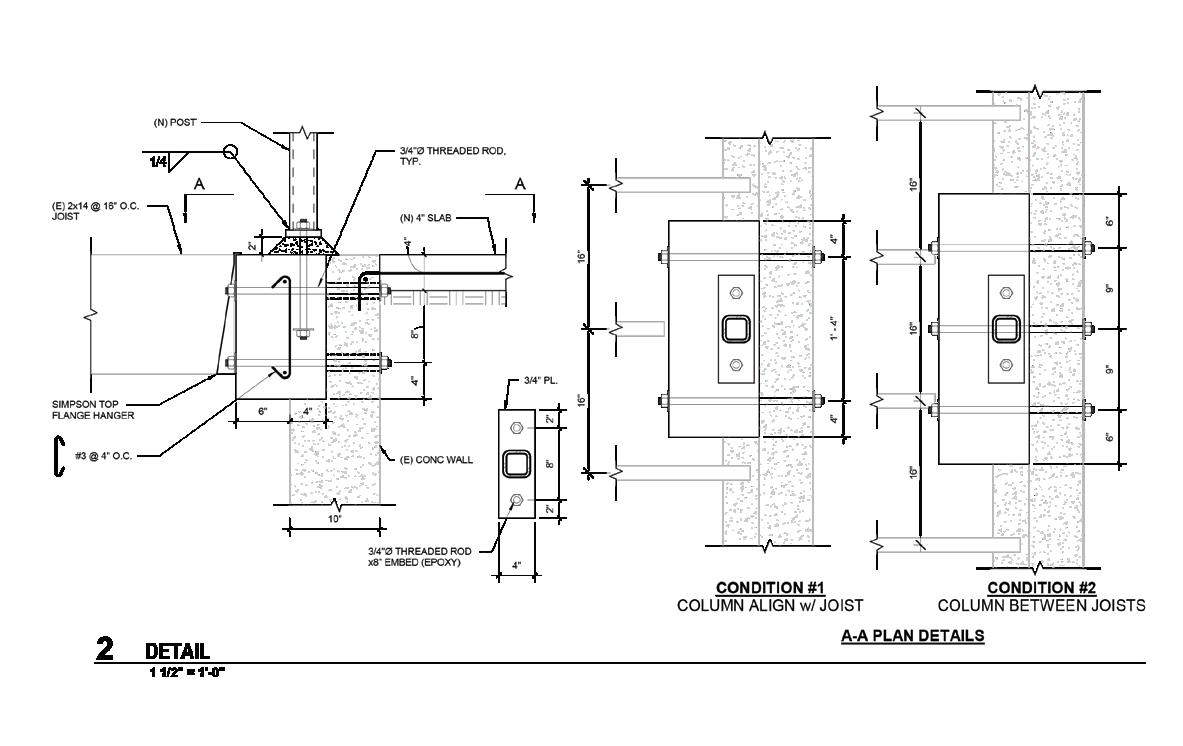
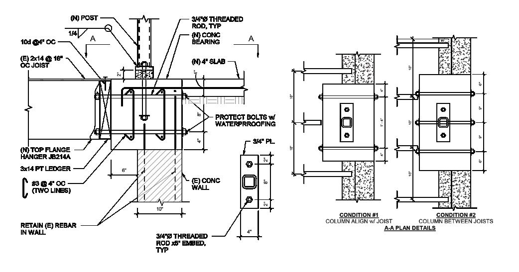
joining a steel post to a concrete retaining wall are shown.
external bolts rather than rebar due to the lack of development length across the width of the concrete. Another alternative I considered was to trim back both the joists and remove the top of the existing wall entirely, save the existing reinforcement, and cast back a larger concrete block to support the post. The second option is clearly better but more expensive. What should I do? What would you do? See Figure 1 for the original details and the two alternatives.
Please think about the aspects of structural engineering you like the best, the fun parts, and write an article for STRUCTURE.■
John A. Dal Pino is a Principal with Claremont Engineers, Inc. in Oakland, California. He serves as the Chair of the STRUCTURE Editorial Board (jdalpino@claremontengineers.com).
CONCRETE guide
ASDIP Structural Software

Phone: 407-284-9202
Email: support@asdipsoft.com
Web: www.asdipsoft.com
Product: ASDIP SUITE
Description: ASDIP Suite consists of 5 software products with over 21 intuitive structural modules, conceived by structural engineers, that will help you in all your daily engineering design tasks. For over 30 years, we have been developing powerful yet simple-touse tools to easily analyze, design, optimize and check your structural members.
RISA Tech, Inc.
Phone:949-951-5815
Email: info@risa.com
Web: risa.com
Product: RISA 3-D
Description: Feeling overwhelmed with seismic design procedures? RISA-3D has you covered with seismic detailing features including full AISC-341/358 code checks. Whether you’re using RISA-3D’s automated seismic load generator, or using the built-in dynamic response spectra & time history analysis/design capabilities, you’ll get designs and reports that meet all your needs.
ENERCALC, LLC
Phone: 800-424-2252
Email: info@enercalc.com

Web: https://enercalc.com
Product: ENERCALC SEL/ENERCALC 3D
Description: ENERCALC automatically incorporates seismic loads in load combinations, including the vertical component, redundancy & system overstrength factors, as applicable. ENERCALC supports ASCE 7’s Base Shear, Demands on Non-Structural Components & Wall Anchorage. ENERCALC also includes earth retention wall modules - including substantial segmental wall improvements, & ENERCALC 3D FEM.
71 MARCH 2024
Monthly 2024 Resource Guide forms are available on our website. Not listed? STRUCTUREmag.org
structural FORUM
Understanding Developing Issues in Access to Design Data Part 2
Implications for Designers
By Joan Malana Kennedy
This is part 2 of a 2-part series about the developing issues in access to design data concerning digital collaborative working environments, particularly BIM. Part 1 discussed the background and BIM development in the UK, and the first reported formal dispute involving BIM in the UK, Trant Engineering Limited v Mott MacDonald Ltd [2017] EHWC 2061 (TCC). This article will deal with the lessons learned about TEL v MML [2017] and the implications and applications for designers.
Design Work Stages and Design Data Exchange
The TEL/MML case illustrates how project workflow has evolved recently. Work stages in different jurisdictions may slightly differ in terminology, but in most instances, the general principles of PreDesign, Design, Construction, Handover, and In Use are followed (RIBA, 2020).
In 2013, the Royal Institute of British Architects Plan of Work (“RIBA PoW”) adopted an 8-stage approach, a change from its 2007 PoW version, which denoted 11 stages. In 2020, the RIBA PoW 2020 was published to correspond to the design and construction industry changes, notably digital innovations that affect project workflow.
RIBA PoW 2020 maintained the 8-stage approach of 2013 but updated the naming of some work stages. It replaced the “BIM Overlay” with a section on “Information Requirements” with an emphasis on two critical aspects: (1) client review and sign off; and (2) information produced at the end of each stage that guides the activities to be carried out on the next stage (RIBA, 2020).
Had the RIBA PoW 2013 and the UK Government’s Digital Plan of Work (dPoW) been utilized on the project at the core of the MML/ TEL dispute, Table 1 provides a high-level comparison of MML’s scope of services with RIBA Plan of Work, UK government's (NBS) Digital Plan of Work (dPoW)* and BS EN ISO 19650-2: 2018 about the level of information that MML would have been required to provide. The AIA design stages (RIBA, 2020) have been mapped out in Table 1 as a comparison with the USA. A more comprehensive comparison table is available in the online version of this article at STRUCTUREmag.org.
It is noted that securing the commission is not strictly part of the Strategic Definition, Stage 0 of RIBA PoW. However, a successful working relationship depends on the roles of all parties being established clearly from the beginning (RIBA 2013). The dispute between TEL and MML was about who owned and accessed the CDE data, which could have been established at Stage 0 – Strategic Definition. The key to a collaborative working environment was an agreement upon the CDE, which established MML would develop via the project collaboration software ProjectWise. Table 1 briefly outlines
the extent and nature of design information a designer is to provide at every work stage. If the RIBA PoW 2013 had been adhered to, MML would likely have had to provide a coordinated architectural, structural, and building services design, updated cost information, and a BIM Level 2 Model at Stage 3. BIM Level 2 is “distinguished by collaborative working and requires an information exchange process which is specific to that project and coordinated between various systems and project participants” (McPartland).
In summary, establishing the design deliverables flowing from the BIM process at the onset of a project is critical. In the MML/TEL matter, the court declined to address whether a contract did or did not exist but guided how essential agreement upon the details related to these deliverables is. Since the employer defines the key deliverables, according to the dPoW, it is critical to know who drives this process to have a clear, concise, and definitive conclusion.
In practical terms, CDE and workflow should be used for managing information during asset management and project delivery. It should be divided into “information containers”: work in progress, shared, or published. The latest standard in BS EN ISO 19650-1:2018 recommends “information container-based collaborative working” to distribute CDE workflow across different platforms.
The Cost of Design Data
The generation of design data comes with a cost. In the TEL/MML case, the evidence showed that the financial harm to MML by a requirement that TEL be given access to the digital deliverable after the first year of design effort was “very little.” This is because the design data was already readily available, although not accessible to TEL. In addition, TEL had undertaken to pay the compensation due to MML. But, MML’s (unremunerated) costs would likely have increased if the project proceeded and MML continued to incur expenses concerning the BIM production without clarity on the issues related to the design data model. As acknowledged in the court’s judgment, MML’s entitlement to a fee concerning the design data would be difficult to identify and value, barring the parties’ agreement on governing provisions.
Conclusion
This case provides an important lesson for designers, who should know that the primary obligation is to perform the contract, with the recoverability of monetary damages coming second. As such, designers should ensure the clarity of their contractual obligations and that the valuation of a breach of contract by the employer
STRUCTURE magazine 72
RIBA PoW 2013
[https://www.taylorfrancis.com/books/mono/10.4324/9780429347085/information-exchanges-richard-fairhead]
Pre-Design Design Construction Handover In-Use
Stage 0: Strategic Definition
Stage 1: Preparation and Brief
Stage 2: Concept Design
Stage 3: Developed Design
Stage 4: Technical Design
Tendering can occur at any time from stage 2 to stage 4 depending on the procurement route
RIBA PoW 2020
Stage 0: Strategic Definition
Stage 1: Preparation and Briefing
Stage 2: Concept Design
Stage 3: Spatial Coordination
Stage 4: Technical Design
Tendering can occur at any time from stage 2 to stage 4 depending on the procurement route
Stage 5: Construction
Stage 6: Handover and Close-out
Stage 7: In Use
Stage 5: Manufacturing and Construction Stage 6: Handover Stage 7: Use
AIA (USA) Not used Not used Schematic Design Design Development Construction Documents Construction Not used Not used
BS EN ISO
19650-2: 2018
1: Assessment and need, includes establishing project’s information protocol
2: Invitation to tender, Includes establishing the appointing party’s exchange information requirements
3: Tender response, includes establishing the delivery team’s (preappointment) BIM execution plan
4: Appointment, includes delivery team’s BIM execution plan
5: Mobilisation includes testing the project’s information production methods and procedures
6: Collaborative production includes information model review
7: Information model delivery, includes reviewing and accepting the information model
dPoW*
Data Drop
1 Comprises modelled response to the plain language questions (PLQs)
MML’s scope
Data Drop 2
Specifies level of definition required to tender the design
Data Drop 3 Information to support the agreed maximum price
Preliminary Design Detailed design; Design coordination
Preparation and implementation of BIM and procurement support
provide an adequate remedy when the designer incurs such damages. This valuation is readily provided when the parties follow the PoW provisions at “Stage 0 – Strategic Definition.” Such valuations are also affected by the procurement model selected, mainly because the level of information to be provided at Stages 2 and 3 may vary, i.e., two-stage design and build contract. Furthermore, suppose the designer acts as the CDE's coordinator and controls the host environment. In that case, this comes with a weighty obligation to other project members, i.e., coordinating the design information, which may have monetary repercussions. These factors need to be considered in the fee entitlement and payment cycle. ■
Principal designer responsibilities
8: Project close-out, includes archiving the project information model
Data drop 4
Maintenance and operation information required to use the finished facility
Development of the DefenceRelated Environmental Assessment Methodology (DREAM)
Full references are included in the online version of the article at STRUCTUREmag.org .
Joan Malana Kennedy is a Senior Consultant in J.S. Held’s Global Construction Advisory Services Practice based in the United Kingdom. She is a designer with a diverse international portfolio who developed her technical expertise working in Singapore, Kuala Lumpur, and the Philippines. She has provided technical assistance with complex and high-value claims in cases in the UK, Middle East, and Southeast Asia. (joan.kennedy@jsheld.com).
MARCH 2024 73
Table 1. Comparison of MML's scope of services with RIBA Plan of Work, UK government's (NBS) Digital Plan of Work (dPoW)* and BS EN ISO 19650-2: 2018. (*Source: based on RIBA Plan of Work 2013 Guide: Information Exchanges
by Richard Fairhea)
structural FORUM
Shaking News! Myths in Seismic Design
The recent CASE Guideline 962-J shares business practice considerations and myths related to seismic design.
By Matt Barnard
Somewhere, the earth is shaking. Earthquakes happen frequently throughout the world but often go unnoticed or are of little concern. Occasionally, earthquakes are much larger with shaking that impacts people and the built environment and cause tremendous loss of life, as we saw last year with the disaster in Turkey. In a world that seems to be more connected than ever, whether through our instantaneous sharing of everything to our global economies and supply chains, we now almost immediately see and then are impacted by these large earthquakes whether we have personally felt the shaking or not.
As structural engineers, we are uniquely able to help our communities mitigate the impacts of these earthquakes. With the continued advancements in the science and understanding of plate tectonics, we better understand the breadth of the seismic hazard facing communities, including those places in where, in decades past, designing for earthquakes was not common. The science and understanding of structures subjected to significant ground shaking also continue to grow. The analytical resources available to engineers continue to improve and allow quicker and more accurate modeling of structures. We continue to bring improvements in detailing and the construction of parts and portions of the structure into our building codes and our typical practices.
While significant resources are available for engineers to learn the latest about engineering structures for seismic hazards, there is less information available about how to go beyond engineering and have a business that is prepared for the impacts of an earthquake. CASE has published CASE Guideline 962-J, “Business Practice Guidelines of Seismic Design for the Structural Engineer,” to introduce readers to seismic and structural engineering and to provide business practices insights. The Guideline outlines some of the basic engineering considerations that will prove useful for those new to considering seismic hazards. There are summaries of the basic theory, key concepts, and differences between new and existing structures. The Guideline also touches on trends in seismic and structural engineering and provides some recommendations on business practice considerations.
The Guideline also highlights common myths associated with buildings and earthquakes. Be aware of these myths if you are going to start practicing where there is an earthquake hazard. Common myths include:
• “My building did fine in the last earthquake, so there is nothing wrong with it.” People wrongly assume that all buildings in a geographic area that survived an earthquake were subjected to the same ground motion. Since every earthquake is different, so are the effects on a given building, even similar buildings near each other. View an earthquake as the equivalent of playing roulette; if your number does not come up this time, it might next time. While a poorly designed structure may survive a given earthquake, that does not mean that the structure will perform during a future earthquake.
• “My building is built to current code, so it is earthquakeproof.” There is no such thing as an earthquake-proof building. A structure designed according to the current code is expected to protect life safety for the code-defined earthquake hazard, but that does not mean that the structure is going to be free of damage or even
repairable. This is often not understood by the public and sometimes not by engineers either.
• “Isn’t code minimum good enough?” Many buildings wrongly assume that code minimum will result in “satisfactory” performance. However, that is defined. The owner will benefit from a candid conversation about what the real expected performance of their building is likely to be. It is also an important way to protect yourself from a disgruntled owner after a major earthquake.
• “The City approved it, so everything with my building is fine.” Just because something was approved does not mean it is compliant with the code or even the right design approach. A rigorous plan check or peer review can be an invaluable service provided to a building owner.
• “The computer model shows that it is okay.” The quality of output from a computer model depends on the quality of input, how the model was built, and the software used. It is important to view the results of any analysis with a critical eye and ask yourself whether the behavior predicted by the model is consistent with what you expected. However, just because a computer model says something is okay does not mean that the result is correct.
• “There has never been an earthquake here, so we are fine.” We all are guilty of trying to predict the future based on our past experiences. But human lives are short compared to geologic time associated with major earthquakes. It should come as no surprise that many owners are surprised that they must consider earthquake hazards when they have never experienced one themselves. However, we need to be patient and educate owners and the public about the hazard and why we are now designing for seismic hazards in areas that traditionally have not done so.
• “My building has been retrofitted, so we are as good as new.” This is one of the most dangerous myths. Often, retrofits only address a specific deficiency that requires immediate action or are targeted at a specific level of improvement. While retrofits are critical to improving the safety of the built environment, these retrofits might not address every problem in a building; they might have only addressed the most pressing ones.
• “That building over there is not my problem; that’s my neighbor’s problem.” When your neighbor’s building falls on yours, it becomes very much your problem. When your neighbor’s building is abandoned because of damage, it negatively impacts you and the entire community.
Have you come across these common myths in your practice? Are there other myths that we should include on this list? Please share them with us. We will gladly continue to update this list so others can avoid the associated pitfalls. ■
Matt Barnard is a Senior Principal with Degenkolb Engineers and is based in Orange County, California. He is a past President of the Structural Engineers Association of Southern California and serves on the Council of American Structural Engineers Guidelines Committee.
STRUCTURE magazine 74








 VULCRAFT VERCO


 Completed project. Photo courtesy of Silman.


