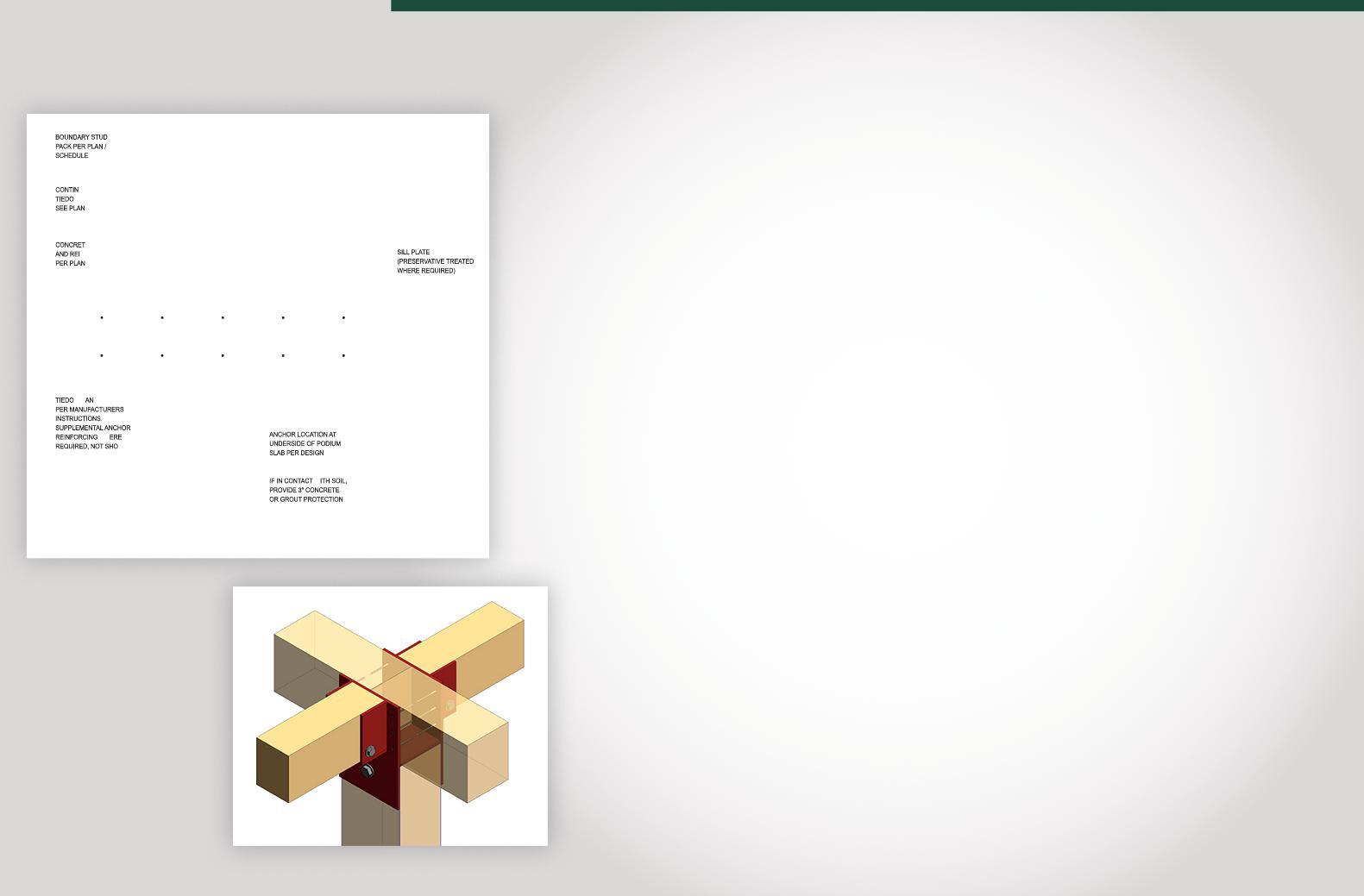



CAST CONNEX® custom steel castings allow for projects previously unachievable by conventional fabrication methods.

Innovative steel castings reduce construction time and costs, and provide enhanced connection strength, ductility, and fatigue resistance.
3
Architects: Rogers Stirk Harbour + Partners
Structural Engineers: WSP
General Contractor: Tishman Construction
Steel Fabricator: Owen Steel
Photography by Wade Zimmerman
Freeform castings allow for flexible building and bridge geometry, enabling architects and engineers to realize their design ambitions.
Custom Cast Solutions simplify complex and repetitive connections and are ideal for architecturally exposed applications.
www.castconnex.com
info@castconnex.com | 1-888-681-8786
WORLD TRADE CENTER, NYALLPLAN
Atlas Tube
Bruel & Kjaer Vibro
Cast Connex
Champion Fiberglass
CSI Computers & Structures Inc
CTS Cement Mfg. Corp
DEWALT
Enercalc


ICC-ES
Keller
MAPEI
NCSEA Summit New Millenium Nucor PCA
Simpson Strong-Tie Subsurface Constructors, Inc. WoodWorks
CIRCULATION
subscriptions@structuremag.org
EDITORIAL BOARD
Chair John A. Dal Pino, S.E. Claremont Engineers Inc., Oakland, CA chair@STRUCTUREmag.org
Jeremy L. Achter, S.E., LEED AP ARW Engineers, Ogden, UT

Erin Conaway, P.E. AISC, Littleton, CO
Linda M. Kaplan, P.E. Pennoni, Pittsburgh, PA
Charles “Chuck” F. King, P.E. Urban Engineers of New York, New York, NY
Nicholas Lang, P.E. Vice President Engineering & Advocacy, Masonry Concrete Masonry and Hardscapes Association (CMHA)
Jessica Mandrick, P.E., S.E., LEED AP Gilsanz Murray Steficek, LLP, New York, NY
Jason McCool, P.E. Robbins Engineering Consultants, Little Rock, AR
Brian W. Miller Cast Connex Corporation, Davis, CA
Evans Mountzouris, P.E. Retired, Milford, CT
Kenneth Ogorzalek, P.E., S.E. KPFF Consulting Engineers, San Francisco, CA (WI)
John “Buddy” Showalter, P.E. International Code Council, Washington, DC
Eytan Solomon, P.E., LEED AP Silman, New York, NY
Jeannette M. Torrents, P.E., S.E., LEED AP JVA, Inc., Boulder, CO

Executive Editor Alfred Spada aspada@ncsea.com
Production
production@structuremag.org
Director for Sales, Marketing & Business Development
Monica Shripka
Tel: 773-974-6561 monica.shripka@STRUCTUREmag.org
STRUCTURE ® magazine (ISSN 1536 4283) is published monthly by The National Council of Structural Engineers Associations (a nonprofit Association), 20 N. Wacker Drive, Suite 750, Chicago, IL 60606 312.649.4600. Periodical postage paid at Chicago, Il, and at additional mailing offices. STRUCTURE magazine, Volume 30, Number 6, © 2023 by The National Council of Structural Engineers Associations, all rights reserved. Subscription services, back issues and subscription information tel: 312-649-4600, or write to STRUCTURE magazine Circulation, 20 N. Wacker Drive, Suite 750, Chicago, IL 60606.The publication is distributed to members of The National Council of Structural Engineers Associations through a resolution to its bylaws, and to members of CASE and SEI paid by each organization as nominal price subscription for its members as a benefit of their membership. Yearly Subscription in USA $75; $40 For Students; Canada $90; $60 for Canadian Students; Foreign $135, $90 for foreign students. Editorial Office: Send editorial mail to: STRUCTURE magazine, Attn: Editorial, 20 N. Wacker Drive, Suite 750, Chicago, IL 60606.


Roadway bridges and highway overpasses are challenging environments subject to harsh chemicals, pollutants and sunlight that degrade components.
Made from durable fiberglass using epoxy resins for strength, Champion Bridge DrainTM safely diverts accumulated rainwater and contaminants from bridges for years to come.

Highway bridge projects also benefit from:
> Light Weight
> Low Installation Costs
> Durable - UV Resistant

> Wide Temperature Range (-60 °F to +250 °F)


> High-Impact Resistance and Memory Retention


Learn more about how Champion Bridge Drain battles corrosion to prevent deterioration and facilitate long-lasting project success.
DOWNLOAD THE INFOGRAPHIC

 ©2016 Champion Fiberglass, Inc.

By
David E. Eckmann SE, PE, FAIAand Matthew
W. Streid, SE, PEChicago’s iconic Wolf Point site, which has eluded development for several decades, is now the proud home of one of the largest technology companies in the world, Salesforce, Inc. The 60-story, 850-foot-tall, glass and steel office tower is the crown jewel of the three-structure development that delivers office and residential living to this vibrant area of downtown Chicago.
40 Structural Sustainability In Search of Net Zero
ByCary Kopczynski, PE, SE, FACI, FPTI
44 Structural Loads
Can Hybrid Roofs Support Snow Loading?
By Yong-wook Jo, P.E., and David Farnsworth, P.E. By John A. Dal Pino By Corey D. Casey, P.E. By Qian Wang, Ph.D., LEED AP and Shahriar By By Jessica Mederson, Partner, Stafford Rosenbaum LLP and Mónika Serrano, Resilience Program Manager, Turner Construction Company ByRafik Gerges, Ph.D., S.E., Sepehr Hemmati, M.S., and Sai Yerradoddi, M.Eng.
58 Structural Design Emerging Risks and Claim Trends in The Design Profession
ByDan Buelow and Mark Blankenship
60 Historical Structures
19th Century Mississippi River Bridges #7
By Frank Griggs, Jr., Dist. M.ASCE, D.Eng,. P.E., P.L.S.
62 Business Practices
Pro-Bono and Low-Bono Work in the AEC Industry
Tallwood 1 at District 56 is a twelve-story mixed-use mass timber building located in Langford, British Columbia, Canada, designed by Design Build Services (DBS), Jack James Architecture, and Aspect Structural Engineers.
By Christopher Pitt, PE, SE, LEED AP, Associate, KPFF
ByMaya Stuhlbarg, PE, SE; Sarah Ruel-Bergeron, RA; Jessica Schneider; Justin Den Herder, PE
64 Fire Protection Updates Updates from the ASCE/SEI Fire Protection Committee
By EricaFischer, Ph.D., P.E. and Negar ElhamiKhorasani, Ph.D.
72 Outside the Box Towards Affordable Housing
By Ramez B. Gayed, M.Sc, Ph.D, P.Eng, Amin Ghali, M.Sc, Ph.D, P.Eng and Chandana Peiris, M.Sc, Ph.D, P.EngPortland International Airport, commonly known as PDX, has been consistently voted among America’s Best Airports by Travel and Leisure Magazine’s reader poll for nearly 20 years, earning the top spot nearly every year. More than that, it is beloved by the people of Oregon and SW Washington as a home base, evidenced by the adoption of the PDX airport code as a moniker for the city itself and by the popular tradition of sharing pictures of your shoes on the iconic carpet to announce you’ve touched down and are officially home from your latest adventure.

It has been less than four years since the 2019 publication of the foundational provisions developed to advance performance-based wind design into practice, and the Structural Engineering Institute (SEI) of the American Society of Civil Engineers (ASCE) is leading the way on two additional steps forward.


The 2019 edition of the ASCE/SEI Prestandard for Performance-Based Wind Design (Prestandard) provided a recommended alternative to the prescriptive procedures for wind design of buildings contained in the nationally adopted standard Minimum Design Loads and Associated Criteria for Buildings and Other Structures (ASCE/SEI 7) that are referenced in the International Building Code (IBC). Properly implemented, the Prestandard results in buildings that can achieve the wind performance objectives specified by ASCE/SEI 7, and in many instances, superior performance. Furthermore, designers, peer reviewers, or the Authority Having Jurisdiction (AHJ) who possess an understanding of wind engineering may adapt and modify these provisions to achieve higher wind performance objectives other than those specifically required by the Prestandard. With original funding from the Charles Pankow Foundation, SEI published the Prestandard in response to the increasing interest in using performance-based approaches for the design of buildings. In addition, the Prestandard aims to help resolve conflicts in performance objectives that exist when using prescriptive procedures for the wind design and performance-based procedures for the seismic design of individual buildings. Major innovations introduced in the first edition include nonlinear dynamic analysis for wind design, limited inelasticity in the Main Wind Force Resisting System elements, systembased performance criteria, and enhanced design criteria for the building envelope.
In February 2023, Version 1.1 of the Prestandard was published to address advances and improvements to the original. The 2023 edition incorporates new developments, clarifications to the original provisions, and updates based upon user experience and comments received since the Version 1.0 document was released. High quality feedback came from users of the Prestandard, who have designed many buildings using its specified procedures. An updated appendix on the procedures used to
determine the overall reliability of the building structure has been included in the Version 1.1 document to help the practitioner and the AHJ verify the reliability of the design being proposed. As was done for the first edition, Version 1.1 is available as a free download from ascelibrary.org.
Coupled with the publication of V1.1, in a parallel effort, SEI has hosted the National Institute of Standards and Technology (NIST) Workshop on Advancement in Performance-Based Wind Design, held in Reston, VA, February 23-24, 2023. The impetus for the project was the extensive casualties and property losses that have occurred over the last several decades as a result of damaging hurricanes, tornadoes and other wind events affecting the United States. NIST has continued to research and provide leadership in the advancement of knowledge of these hazards and to the development of standards that will lead to more resilient communities across the nation and around the world.
The purpose of the workshop was to assess the current state-of-the-art in performancebased wind design (PBWD) and to support the future development of a Measurement Science Roadmap for advancing the knowledge in this area and its application in practice. The workshop scope included the following three broad subject areas, with associated sub-topics:
• Subject Area: Performance-based wind design (PBWD)
• Sub-Topic 1: Review of current state-of-theart on PBWD
• Sub-Topic 2: Identification of research needs and prioritization for standardization and application in practice.
The workshop convened 53 subject matter experts from around the country and across the globe to identify the highest priority research needs that are required to advance PBWD from the current state-of-the-art to the ideal future use.
The framework adopted for the workshop to advance PBWD into practice consisted of deep consideration of five key areas essential to the overall design process and verification. These areas include the work in determining the wind hazard characteristics, the overall structural system and building envelope reliabilities, understanding the wind-structure interaction, structural analysis techniques, and the design
methodologies for the overall building.
The workshop participants identified a broad range of research and development activities to advance the use of PBWD with the goal of reducing the impacts of these severe wind events, including discussions and specific recommendations on the following 10 topics:
1.Development of main-force wind resisting system (MFWRS) reliability,
2.Development of components and cladding (C&C) reliability,
3.Integrate performance between structural system and cladding,
4.Thunderstorm/Tornado characterization,
5.Characterize hazard and loads for both short and large return periods,
6.Structural and material properties,
7.Improve physics-informed, computationally efficient methods for nonlinear analysis of wind response over long-period durations,
8.Static pushover for wind engineering to quickly evaluate nonlinear structural performance,
9.Confirmation of loading protocol, and
10.Economic study to identify existing buildings at risk.
The final report describes the outcome of the workshop in detail and will be used by NIST to develop a Roadmap for the standardization and application of PBWD that is to be developed by wind engineering practitioners and researchers for buildings. The final report will be available as a free download from NIST and from the SEI Website.
PBWD has seen many recent developments in both established provisions and use by the practice. SEI is leading the way – along with partners such as NIST and the Charles Pankow Foundation – to take the next steps forward and continue advancing wind design into performance-based approaches.■
Bill Baker is one of the world’s leading structural engineers. He has designed innovative structures that range in scale from single-family homes and small pedestrian bridges to the world’s tallest manmade structure, the Burj Khalifa in Dubai. His cutting-edge designs include the unique Broadgate Exchange House in London—which is both a building and a bridge that spans over Liverpool Street Station—and the cable structure entry pavilion for the General Motors Headquarters in Detroit. Additionally, Bill is widely recognized for his collaborations with renowned artists, such as James Carpenter, Janet Echelman, Iñigo Manglano-Ovalle, James Turrell, and Jaume Plensa.
“Structural innovations move architecture forward. They create new design opportunities that can lead to new architecture. The designs of many of our most famous buildings are based on structural innovations.”
Many of Bill’s structural innovations are a result of his extensive research in structural systems, which he shares through his teaching, lectures, and numerous publications. He is an Emeritus Honorary Professor at the University of Cambridge and has also taught at MIT, the University of Illinois at Urbana-Champaign, Illinois Institute of Technology, Northwestern University, and Princeton University.

Bill has received honorary doctorates from the University of Stuttgart, Heriot-Watt University, the Illinois Institute of Technology, and the University of Missouri. He has been honored with the Gold Medal from the Institution of Structural Engineers (IStructE); the American Society of Civil Engineers (ASCE) OPEL Lifetime Award for Design; the Gustav Magnel Gold Medal from the University of Ghent; the Fazlur Rahman Khan Medal from the Council on Tall Buildings and Urban Habitat; the Fritz Leonhardt Preis and the Torroja Medal from the IASS.
Could you share some information about your personal and professional background, as well as what motivated you to pursue a career in structural engineering?
I grew up in a small town in Missouri and always enjoyed studying math, science, and history. When I was in high school, I took an aptitude test that suggested I might want to be an engineer, and at that time, I “didn't” know what an engineer was. When I asked my mother about it, she said that my grandfathers had been engineers, although they had already passed away long before I was born. As I looked into various engineering fields, I thought creating something as substantial as a bridge would be interesting, and I ultimately chose to pursue structural engineering. It was only later that I discovered that both of my grandfathers had pursued careers as structural engineers.
Can you share your experience of the initial years you spent at SOM, and discuss the state of structural engineering leadership during thatperiod?
When I joined, SOM was certainly a robust practice, with engineers in many offices—Chicago, New York, Houston, Denver, and San Francisco, to name a few. At that time, the firm had recently completed the Hancock Tower and the Sears Tower, and was almost finished with the Hajj Terminal, so there were very remarkable structures coming out of SOM at the time. As a junior engineer, I worked on a supertall project under Fazlur Khan before he passed, and I developed concepts that I later published in an article. I
also worked with Senior Engineers John Zils and Stan Korista, and on various projects and papers with Hal Iyengar, who was the senior partner after Faz passed away. In the 1980s, I assisted Hal when he served as chair of the Structures Congress in Chicago; when the organization returned to Chicago several years later, I served as chair.
Can you share your journey as a pioneer in designing tall buildings, starting from your initial involvement in a high-rise project to your most recent work?
Many contemporary tall building technologies of that era were invented by SOM working with architectural students at the Illinois Institute of Technology (IIT). At the time, SOM partners Myron Goldsmith and Fazlur Khan were teaching at IIT and were coming up with ideas about structure that would lead to new architecture. When Faz died, I and others stepped in to help and started working with graduate students.
As a junior engineer, I spent a lot of my workday doing as I was told in the office, while on the weekends, I worked with Masters’ students on their thesis projects. They would always ask me what felt like rudimentary questions about why things were done in a certain way, which forced me to think hard about my answers and reflect on my professional work.
Back at the office, when new projects would come in, a friend and I would guess what the structural system might be before it was chosen. We would then compare them with the direction set by the leadership— sometimes we thought ours were better, and other times ours were not as good. I worked on several projects under John and Stan, one of which included a slender 27-story building in Chicago, which taught me a lot about the stability and design of tall buildings as well.
The more experience you have, the more ideas you can generate for the next project. This experience can be from past projects, research, conferences, discussions, and studying the work of others.
The Hancock Center and Willis Tower achieved incredible heights with remarkable material efficiency at a time when no one talked about sustainability. Tell us, how did this inform yourdesigns?
A lot of SOM’s hallmark work is largely driven by efficiency, which has always been central to the firm’s philosophy. This, of course, was very influential in the work of Myron and Faz, who were always looking for systems that were as efficient as reasonably possible—for economic and philosophical reasons. Back then, sustainability wasn’t spoken of as much as now, but efficiency has always been inherent in what we do.

Many of the greatest stories of innovation are primarily driven by the goal of the economy, not just in tall buildings but also long-span structures or bridges. Much like in nature, efficiency drives innovation in the creation of new systems.
How does the structural design of buildings classified as "super-tall towers" differ from those that are typically categorized as "mid-rise"? Is it appropriate to compare structures such as the Hancock Center, 100 Mount Street, or 800 Fulton Market? What are the shared and distinctive structural features of these buildings?
One of the things that Myron Goldsmith did in his Master’s thesis with Mies van der Rohe was draw a series of bridges of different lengths, demonstrating the different systems required for each of the spans. For plants and animals, different species also work at different scales. In the same way, while low-rise, mid-rise, and high-rise buildings all resist forces like gravity and lateral loads, in reality, the scale of the problem changes dramatically. The program of the building also affects the system—whether it’s office, residential, or mixed-use—each of these typologies come with different constraints that ultimately fuel the creative process.
Among many other examples, the Hancock Tower is a product of its constraints with its diagonal braces that are both aesthetic and functional. How would you do that with concrete? There have been various experiments in New York and Chicago where you take a concrete tube and fill the windows with concrete to create diagonal bracing. 100 Mount St. and 800 Fulton Market take a different approach—they’re both fundamentally concrete buildings braced with steel. Historically, there’s a reason that this was not achieved in this way, and we’ve studied those issues and have been able to address them. We have not only demonstrated that it can be done but also that it can be done efficiently.
Can you provide a brief overview of the research projects that you have spearheaded at SOM, and how the insights gleaned from these studies influenced your design approaches?
As I mentioned, in the 1960s, Myron and Faz led a lot of the research at IIT, and many of the systems we use today were invented and developed by SOM during this era. Research has, in many ways, been integral to the firm’s culture ever since. The big difference is that eventually, it moved in-house—sometimes both in formal or informal capacities.
A few years back, we had two parallel organizations. One was architecturally focused, called the “Black Box” group for computational design. The name was ironic, as it was all about opening the black box! The other, I would call the research gang, which was a casual structural engineering-focused group.
Now we have an official practice called Research and Innovation (R+I), which is cross-disciplinary, tackling everything from structural ideas to furniture design, lighting, and beyond.
As a multidisciplinary firm, what distinguishes SOM’s process from others, and how has it influenced the successful construction of numerous tall buildings around the world?
It’s not an accident that SOM has done such an enormous number of tall buildings worldwide. These are very technical problems, and I would say that SOM being an “AE Firm” with world-class architecture with a capital “A” and world-class engineering with a capital “E” enables us to
do that. There are a lot of firms out there that have both disciplines, but few that place the same emphasis on each. Our architects and engineers also challenge each other to be the best and don’t accept less than that. Over many years, we have found many advantages to having such an integrated practice.
In what ways do you believe that your role as a mentor has influenced the development of the field of structural engineering within SOM? Additionally, with the recent appointment of Eric Long as a new structural engineering partner, how do you anticipate that the discipline will progress in the future?
The leadership of the structural group at SOM has evolved, and although there is much common ground, everyone has a different focus.
Mine was more on pure blue-sky research, where we would investigate interesting things that we didn’t know much about nor understand if they had a practical use. But I would say that almost 100% of the time, we found a practical application for knowledge we gained. One of the things that I’ve always enjoyed about SOM is that the research is done by designers actively working on projects, not a siloed group, which I think certainly helps.
Much of the work we’ve been doing is in seismic zones, and there has been a lot of fascinating research on the West Coast produced by people like Mark Sarkesian and Eric Long. Eric has led incredible tall building projects in Mexico and directed some creative work for the LACMA with Peter Zumthor. He is also leading his own research, which I find incredibly exciting.
In light of your many years of teaching experience, how has academia contributed to your career and your understanding of the profession?
A lot of what I know now I was never taught at school because my professors didn't have the knowledge to share. One of the things we try to do at SOM is to share our knowledge and experiences. I remember hearing Fazlur Khan give a talk once at an engineering dinner, where he said that his goal was not to patent but to publish… and then to go on to the next idea before anyone else got there! He was certainly successful at that.
Now that we’re more focused on sustainable solutions, we know a lot that can make buildings significantly more efficient and enable other designers to find these systems more easily than they have been taught. At SOM, we put considerable effort into publishing and teaching our work. It is said that if you think you understand something, try writing a paper about it, and you will usually find holes in your knowledge. If you really think you understand it, then try to teach it. In teaching students, we typically find that we teach ourselves and learn what we think we know in much greater depth.
We’ve had the opportunity to work with several brilliant students, some of whom we've hired. Many of them are doing things that I find remarkable.
Out of all the tall buildings that I had nothing to do with, the Hancock is my favorite. I like a lot of structures, but the Hancock is quite extraordinary. It’s so clear and effective. It’s truly an amazingly sophisticated solution at a time when the computational power was more limited. While it’s true that we know more now than we did then, I would say that it’s still hard to beat that one.■

 Upper building at dusk. Photo courtesy of Steelblue and Pelli Clarke & Partners.
 By David E. Eckmann SE, PE, FAIA and Matthew W. Streid, SE, PE
Chicago’s iconic Wolf Point site, which has eluded development for several decades, is now the proud home of one of the largest technology companies in the world, Salesforce, Inc. The 60-story, 850-foot-tall, glass and steel office tower is the crown jewel of the three-structure development that delivers office and residential living to this vibrant area of downtown Chicago.
Wolf Point, named after a Potawatomi Native American who once lived on the site, is located at the confluence of the North, South, and Main Branches of the Chicago River. Situated within Chicago’s central business district, the site sat dormant for decades, primarily due to its limited access and a 50% view corridor requirement mandated by the Apparel Mart directly to the north. The site is also at the end of a peninsula, making it susceptible to higher wind pressures coming down the Chicago River. Bounded by water and limited road access, development plans came and went, each hampered by site logistics and constraints.
That all changed in 2012, when private developers Hines Interests LP and Park Holdings Group LLC, the principal investment entity of the Kennedy family, set their ambitions on collectively developing the challenging site. The development team pulled together a strong project team that found solutions to construct this slender office tower, which is sandwiched between existing residential towers to the east and west and located only a few feet from the Chicago River to the south.
The slender tower located on the site’s southern tip is exposed to substantial winds traveling north and west along the river. This “urban canyon” along the Chicago River framed great views but did not provide the level of wind protection at the Wolf Point site typically afforded by the skyscrapers of the Chicago Loop. The wind funneling between tall buildings along the river can create unusual wind loads on the tower.
Engineers performed wind tunnel studies to determine the best tower orientation on the site and to sculpt the tower’s top to reduce the wind loads optimally. According to the studies, the wind pressures channeling down the river closely resembled an Exposure Category C rather than the more typical Exposure Category B found in Chicago’s urban development. The increased wind loads on the tower required a robust lateral system to resist the horizontal wind forces and associated overturning moments.

The active winds at Salesforce Tower Chicago are resisted by a central concrete core lateral system that wraps 26 elevators, exit stairs, restrooms, and primary vertical MEP/FP risers. With an aspect ratio of 20:1, the concrete core alone does not provide enough stiffness to meet the tower’s strength and serviceability requirements. To achieve the required strength and stiffness, a two-story mechanical space at Levels 38 to 40 is used to introduce steel truss outrigger trusses that reach out to perimeter columns to stiffen the concrete core. The outriggers widen the building’s stance to a modest 7:1 aspect ratio. The large wind forces require each truss to deliver nearly 4,500 kips of horizontal load and 3,000 kips of vertical load to the core. Domestically produced A913 high-strength steel (65 ksi) is used for the various truss members to resolve the loads with smaller member sizes than conventional steel. High-strength steel is also utilized for all gravity columns to further economize the steel tonnage. The use of high-strength steel
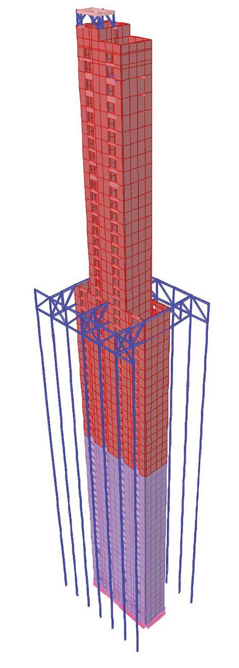
reduced the project tonnage by approximately 500 tons, resulting in smaller foundations, cost savings to the owner, and lighter “picks” for the tower crane. A well-conceived bolted connection detail distributes the large outrigger forces throughthecore/outrigger truss interface. Two 3.5-inch-by-24inch steel tie-plates are embedded through the core wall, providing continuity
between the steel truss chords on each side of the core. These double tie-plates penetrated the core formwork, allowing a double-shear bolted connection through the web of the jumbo W27x539 chord members. The erection team recognized the importance of the extremely tight tolerances required to install these tie-plates. Detailed plans were carried out with the help of robust erection aids, multiple survey shots, and carefully executed ironworker choreography.
A two-story steel belt truss is provided along the perimeter, perpendicular to the outriggers, to distribute outrigger forces across all seven columns on each side of the tower. The steel belt trusses reduce peak demand in each given column and, more importantly, minimize unbalanced transient axial stresses at adjacent perimeter columns. At 60 stories tall, it is critical to evaluate the perimeter column’s elastic shortening during erection to achieve floor levelness in concert with the stiffer concrete core. Traditional gravity-only columns are more highly stressed than outrigger columns that are oversized to provide increased axial stiffness. The belt trusses allow the perimeter columns to be more uniformly stressed
and minimize differential shortening between adjacent columns, ensuring tighter tolerances when installing the enclosure system.
The surrounding river and limited site access created challenging logistics for the construction. Salesforce Tower was the last of three structures to be built within the development. Also, it was in the most precarious location—sandwiched between tall residential towers to both the east and west and an existing garage to the north. Fortunately, the design team of the east residential tower anticipated this challenge by designing a two-story haul road within its below-grade parking structure to connect the only site access road to the tower’s future loading dock. This loading dock served as the primary layout space for contractors, with all deliveries, including steel beams and trusses, passing through the below-grade haul road. The tower’s loading dock, which was eventually covered by a public plaza, remained open to the sky throughout construction, allowing the tower crane to pick materials directly from the truck beds and lift them to the working deck.
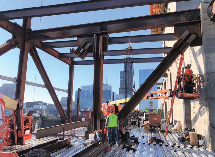
When the building topped out and the tower crane was dismantled, the loading dock was covered to finalize the plaza construction. The expansive public plaza ties the streets, river, tower lobby, and retail together. The heavy plaza loads, comprised of deep soil and public assembly loading, are supported by a series of long-span concrete beams that clear-span the column-free loading dock below.

The typical floor plates are configured to maximize the views above the river, and the tower’s base is shaped to maintain the required view corridors through the site. The primary floor plate steps inward below Level 7, then again below Level 4 to open views through the site required from the north. These setbacks result in 80-foot-tall perimeter columns with only one discrete point of bracing at Level 4.
The final setback defines the two-story lobby as a columnfree space, with Level 3 hanging from Level 4. The lobby’s defining architectural feature—a downward cantilevered glass fin wall — hangs from Level 3 to provide a thin glass wall that envelopes the first floor’s entire perimeter. A construction analysis was implemented to predict the movement of the multi-tiered hanging support relative to self-weight and the future build-out of the space. The large, cantilevered slab edge supporting the glass fins was soft-shored around the perimeter, leaving an intentional gap to account for the anticipated deflection while maintaining a constant, level elevation around the perimeter to bottom-out the slab edge as the concrete was placed. This maintained the stringent elevational tolerances necessary for the glass fin wall installation.
A critical component to reducing high-rise structural costs is to design an optimized typical floor plate, as the benefits or mistakes are repeated throughout the height of the tower. At Salesforce Tower, the architect introduced several re-entrant corners around the typical plan to maximize perimeter glass area, creating space for 12 corner offices, 10 of which are column-free. The column-free corners provide architectural benefits, but also eliminate the need for two columns at each floor level. The columns are replaced with carefully tuned cantilevers coordinated with the mechanical distribution system. The project team worked closely to economize potentially costly edge details and standardized the myriad of corner and notch conditions essential to the building’s iconic form.
The project team designed and implemented a rigorous surveying and monitoring program for the structure. The contractor, erector, and structural engineer established a direct line of communication to expedite the review of the frequent survey results with three rounds of data per tier (two floors). This allowed the team to create a quick feedback loop on column shortening that was continually calibrated with staged analysis modeling using ETABS results that were postprocessed in Excel. This data informed the column shim adjustments
Project Team
Design Architect: Pelli Clarke & Partners
Architect of Record: HKS
Structural Engineer: Magnusson Klemencic Associates
MEP Engineer: Alvine Engineering
General Contractor: Walsh Group
Concrete Subcontractor: Walsh Group
Steel Fabricator: Cives Steel Company
Steel Erector: Danny’s Construction Company
Connection Engineer: Drucker Zajdel Structural Engineers
necessary to react to the erection, column shortening, and differential settlement variables around the building perimeter to confirm the structure was within tolerances.
Salesforce Tower Chicago topped-out in May of 2022 and is on track to open later this year. Open communication between the design, construction, and ownership teams was key to maintaining the project schedule on this challenging site and the tower’s ultimate successful completion.■




 By Yong-wook Jo, P.E., and David Farnsworth, P.E.
The already deteriorating Pier 54 was further damaged by Superstorm Sandy in 2012. Hudson River Park Trust, the public agency that oversees the parks along the Hudson River in lower Manhattan and converts existing piers into public parks, decided to replace the pier with a new kind of public park on the river. A philanthropic foundation generously funded the project, and Heatherwick Studio in London was commissioned to guide the vision of creating informal, playful, and educational public space into a reality. The idea was to create an undulating landscaped park with a plaza, performing spaces, and overlooks surrounded by the lawn and trees.
It was evident from the moment we saw the early renderings from the architect that the conventional way of engineering and documenting would not work for this highly complex geometry. Heatherwick Studio actively used the parametric Grasshopper scripts in Rhino 3D to generate the entire geometry. As we were aware of the potential of the parametric design to automate the process and respond to changes very efficiently, we decided to adopt the same strategy. We worked closely with Heatherwick to develop the scripts. Heatherwick
became responsible for outer curved surfaces with our inputs on how to make them structurally sound and fabrication-friendly and achieve economy by grouping some ‘pots’ into the same geometry. At the same time, they could have different heights to make elevation changes. We then took over the script and appended it to generate inside and side faces, allowing the pots to have the required structural sections. We also made all our surfaces flat, so the curved formwork is only needed for the outer surface. As a result, all surfaces were generated by the script. Not a single surface was created manually in Rhino software.
We took the further step to generate all rebar details, such as sizes, locations, lengths, hooks, and splices, with the scripts. The outcome was a full rebar detail model with each bar identified with a unique mark. The fabricator could then bend and cut the bars exactly as needed at the suitable locations.
During construction, two of the total 132 pots had to be redesigned because obstructions required some piles to be relocated. Within a couple of weeks, along with Heatherwick, we could generate the pots’ full design, including all the element geometry, steel connections joining the precast elements, and concrete reinforcing, and feed into the fabrication. Without the automated scripts, a significant delay would have occurred.
The need for electronic information transfer was identified during the mock-up in the construction phase. It took days to convey the geometry of the pots and rebar to the precast contractor in 2D drawings and to provide explanations via telephone calls. The contractor decided to invest in learning 3D software and scripts, and when the production for the project started, they could receive the Rhino files of the pots and rebar and turn them into 2D drawings for the shop and the engineer’s review.

Casting precast elements that have two-way curved surfaces was the major challenge. Various methods were proposed and tested, and CNC-milled foam for formworks were chosen since the exact geometry information was available in the 3D models. When the sourcing for the milled foam formwork was found unable to meet the project schedule, the fabricator decided to invest and set up a milling shop for the project. This shop eventually spun off into a separate business as the demand was very high.
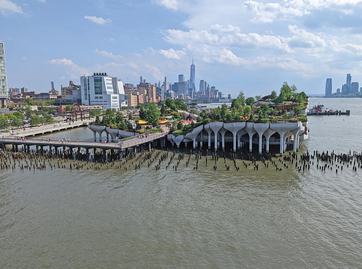
Another challenge in the construction was the assembly of the pots. The construction manager and the marine contractor had numerous discussions with the client, designers, and the precast fabricator to develop the best possible way. The plan was to set up the assembly stations in a remote yard near the precast fabricator to minimize the land transportation of the fabricated precast. A yard at the Hudson River shore was chosen so that the assembled pots could be barged to the site. This method proved to be best as the assembly required lots of welding and could be done in an almost indoor condition.
The importance of collaboration and trust among team members for this project must be addressed more. It was the true driver that made the landmark project a reality. Several challenges were evident from the beginning. The design team worked together rigorously to develop and share the scripts to generate, rationalize, and transmit the complex geometry. The contracting team was open-minded and willing to try, embrace, and invest in new digital fabrication technologies which were critical to the project. The client team trusted and encouraged the whole team to develop innovative ways to deliver the project. We
appreciate all project team members’ great collaboration and the opportunity to be part of the new icon on the Hudson River.■View of Little Island from Pier 57. View of the Pots from the river.
In the past few months, I have watched a few webinars on structural engineering topics and have come away wondering why I wasted my time. It wasn’t so much the technical content per se or the knowledge or earnestness of the presenters but the poor quality of the presentations themselves disturbed me so much that I couldn’t focus on the content. The words just became “blah, blah, blah,” I tuned out and became a movie critic with running commentary. Many of you might already be thinking that if I am such a presentation hotshot, why I don’t do them myself and show us how it is done. Hence this article.
I do not have a formal educational background in communications. But I have a wealth of practical experience and, as a consumer of information, feel compelled to share some thoughts on how engineers can do better. This article addresses presentations one might give in an in-house business setting, at a client presentation, an interview for a potential project, or a webinar.
This is the most important takeaway I can offer. In preparing for a presentation, give considerable thought to the audience: what they know and don’t know, what is and is not of interest to them, and what you think they want to learn from you. If you aren’t sure about any of this, then ask someone who is. I can’t count the number of presentations I attended when the topic was something that most of the audience wasn’t particularly interested in or had seen before - to some extent, a rerun, you might say. I wish the presenters had asked other people about the proposed content and their thoughts. It would have saved everyone a lot of time, and more important topics could have been discussed. I highly recommend that an appropriate amount of time be spent putting together the presentation, so it doesn’t come across as poorly planned or thrown together at the last minute.
Once you have this basic information down, craft an overarching story woven together with the information you want to convey and present it in a manner that the audience will find interesting. Everyone likes a good story.
Like any good movie, your presentation needs to start strongly. Start with what you are going to tell them. This engages them and grabs your audience’s attention. I love the opening scene of the original Top Gun movie. When the blast detectors flip up, the music gets louder, the afterburners ignite, and the pilot salutes the carrier deck crew, I know I am in for a good time.
Then tell them. Have a reasonable number of important topics you want the audience to take away. Something like three or four. If you get to the end and the audience can’t remember the first few things you mentioned, you have too many topics. It is important to stay on point and stick to the script. If you start wandering, your audience’s attention will begin wandering too. And there is always the need to finish on time.
Then tell them what you told them. This is executive summary time. It is not time to repeat the entire presentation. You need to repeat the three or four main topics and why they are important to the audience. Takeaway: Make an interesting presentation so that the audience feels it was a good use of their time.
When explaining technical topics, provide a broad framework, and then move on to simple examples that allow the audience to understand the main points. Add bells and whistles if necessary. This approach lets the audience ramp up to the “same page” as the presenter. Going straight into highly technical issues will leave the audience scrambling to catch up, generate lots of questions, or worse, likely tuning out altogether. A recent webinar I watched dealt with the design of lateral bracing elements for steel buildings. Rather than start with an example building that was symmetrically square or rectangular, the example building had a plan irregularity (re-entrant corners) and had torsion (due to the location of the braces relative to the center of mass). The building code requires so much additional computation for the design of irregular buildings that the lesson on how to design the bracing elements was obscured.
An analogy comes to mind. Beginning pilots start by learning how to fly simple, one-engine planes. This is so that they can focus on learning how to fly. After they master that skill, they graduate to two-engine planes, which I understand are significantly more complex and harder to fly. The extra difficulty is not so much the flying part but because there are so many other things that can go wrong, like losing an engine during takeoff. Engineers who try to learn how to design a highly complex system before they understand the basics will forever follow an example they saw in a book without really understanding what they are doing or why. Crashing hurts.
Takeaway: It’s okay to keep things simple. You don’t need to explain every facet of a topic to your audience.
It’s okay to keep things simple. You don’t need to explain every facet of a topic to your audience.
Graphics need to add information that mere words cannot convey. Use your graphics to present visual information that supplements the spoken word, not repeat the words the presenter will speak. The audience can either listen to you or read your slides, but they can’t do both simultaneously.

Too often, presentations contain graphics that could be in almost any presentation since they basically all look the same, are too small in scale for anyone that doesn’t have the eyesight of a military pilot to read, or are of a nature that the viewer can’t immediately recognize what they are seeing.
As an example of what doesn’t add value, I think about hysteresis loops. Showing them is essentially a waste of time. We know that laboratory testing produces such data, and the loop shapes are important in judging the test results. If one is writing for an academic journal, they need to be included, but not in most general interest presentations. Just say that the hysteresis loop is pinched or not pinched and move on. Give your audience a little credit and assume they know what you are telling them. Graphics that only look good at a full-screen IMAX theater don’t work in a PowerPoint presentation or many other places. If you have to explain to an audience what they are looking at, then the graphic is too small.
Most engineers are not the greatest photographers. Every marketing professional that I have ever met has said in my presence, “I wish the engineers had taken some decent pictures when they were there.” Mobile phones have improved the situation when it comes to taking a picture, since the phone’s camera is smarter than the photographer. Again, if you feel the need to explain a photograph to the audience, pick another one.
Also, don’t show an image, graphic, calculation, or formula and then immediately say, “we don’t have time to go into that today.” The audience naturally then asks themselves why you bothered to show it to them in the first place. Or they wonder if the presentation they are watching is a re-run that was pruned down from a larger presentation that you have given before but were too lazy to edit for them. During one of the recent presentations that I alluded to at the outset, the presenter mentioned this four or five times.
Takeaway: A few understandable and informative graphics are far better than too many.
Speak in a style and pace that conveys to your audience that you are honored for their invitation and allows them to comprehend what you are telling them. Make and hold eye contact. Don’t read from your notes. Speaking to strangers doesn’t come naturally to many people, engineers particularly, so don’t feel bad. Neither does hitting a golf ball or a 90-mileper-hour fastball. But you can take lessons, practice, and get better. No one expects an engineer to be a good speaker, so being above average puts you in elite company.
When I was a young engineer, my employer encouraged many staff to take a two- or three-day class called Speakeasy. It was a public speaking boot camp that taught the basics and emphasized the benefits of practice, as embarrassing as that can be when you have to watch yourself on a recording. We practiced during the day, then later in front of a mirror by ourselves, and finally in front of our families in the evening after we
went home. I can still picture the people and the room after over 30 years. I don’t recall that anyone really wanted to attend the class, but after we graduated, we were all happy that we did. Our families got a good laugh too. I understand that Toastmasters is also good.
Takeaway: Put in the effort if you want good results.
I said earlier that the most important takeaway was to have a compelling overarching story. But I was wrong. The most important thing is to practice delivering the presentation. Engineers who are not fond of making presentations naturally are not fond of practicing either, but if you don’t, all is for naught. Several issues can be corrected while practicing: 1) the overall message, 2) the content, 3) the graphics, and 4) the time.
I recommend that you get an audience of two or three people to listen to the presentation. They will be able to critique your message and help you emphasize the necessary points. When you hear yourself speak, you will likely immediately self-correct your message and decide what should be left out and what to add. When you get really good, you won’t need notes. After you have practiced several times, the flow becomes more natural, and your notes become less important. This feedback is essential for webinars since the presenter will not receive visual clues from the audience.
Speakers have an idea in their heads as to what the important points are or the content they want to convey, but until the words are spoken, they really don’t know how it will come across. Your practice audience will be able to critique the words you choose, the graphics, and the points of emphasis and let you know if your message registered with them or not. If you are like me,
sometimes the words leave me at a dead end that is difficult to get out of. Now is the time to fix the presentation, not during the after-presentation de-brief when all of the “I should have done this and that…” comes out.
Presenters always want to show more graphics (or words) than are necessary. The graphics supplement the spoken word. An experienced presenter knows that if there is more than one picture or slide for every two or three minutes of presentation, there are too many.

And lastly, focus on time and pace. An excellent presentation will finish on time without leaving time on the table or rushing to the end. This demonstrates respect for the audience and shows them you are committed and took the time to get everything right for them. If this is a presentation to a client for a project, this will instill confidence in them that the project will be well done too. Now is the time to do some pruning so that your actual presentation doesn’t become a race to flip through all of the slides before the clock hits 0:00 or you say, “We don’t have time to go into that today.”
Takeaway: When you think you have practiced enough, do it one more time. In conclusion, tell an overarching story, with an explanation at the beginning of what you will tell the audience and conclude with the summary. Use easily understood examples supported by graphics that the audience can readily comprehend. Work on your speaking skills, even if you think they are adequate, and then practice, practice, practice. And then practice some more.■

Specify cladding and curtain-wall connections with the new Edge-Tie™ system from Simpson Strong-Tie. Designed with a unique, extruded shape and pour stop, it provides two times the load capacity of traditional bent plates. This innovative solution utilizes bolts that allow installers to easily position and adjust anchors along a continuous slot. By eliminating field welding, the Edge-Tie system speeds up building enclosure while saving time and labor costs. It’s simply a smarter, faster way to get the job done.
Engineer your next project with all of our structural steel solutions. To learn more, visit go.strongtie.com/edgetiesystem or call (800) 999-5099.
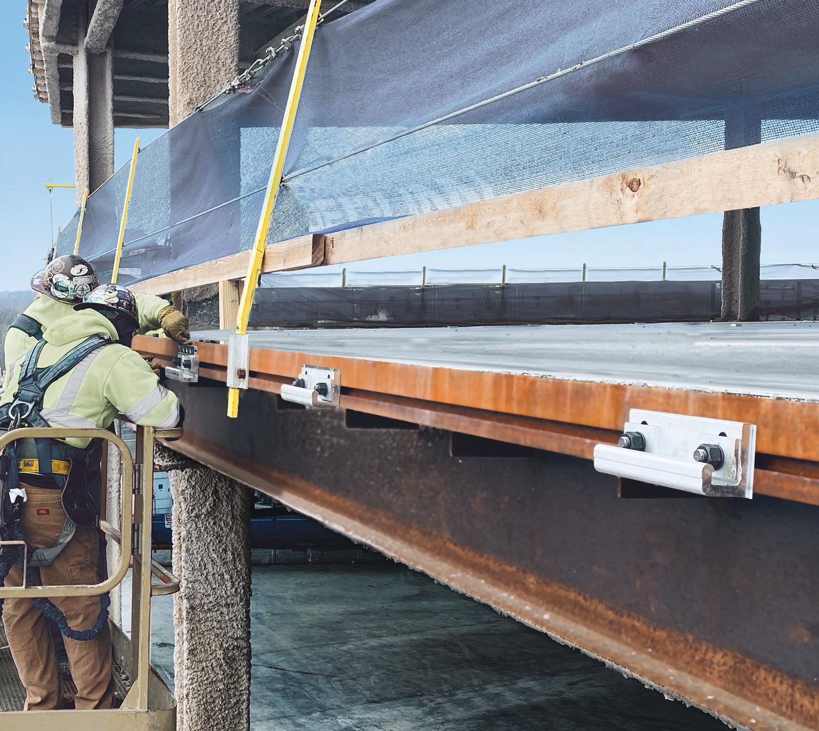 The Edge-Tie™ System
Most structural engineers learn about live load reduction (LLR) for the first time in school. If you are lucky, you may even be presented with the basic equation for LLR from ASCE 7 (ASCE 7-16: Minimum Design Loads and Associated Criteria for Buildings and Other Structures) and given a simple problem to work through, where the reduced design live load can be determined as follows:
L=L0 (0.25+0.15√(KLLAT)) Eq. 1
where L0 is the unreduced live load, KLL is the element factor, and AT is the tributary area. In the author’s case, he did not learn about LLR until his first job. He was asked to perform LLR on a 12-story boomerang-shaped building with irregular grids, curved slab edges, elevator core walls, and many transfer girders. To make things worse, the firm was not using analytical software that could compute live load reduction. So it had to be done manually. And, of course, it had to be done fast and efficiently because the project was already over budget and needed to make up time in the schedule.
LLR is important for column designs but less critical for walls as they are typically part of the gravity and lateral load resisting systems, and the lateral forces generally govern their designs. It is, however, important to consider the walls as they relate to determining the tributary areas to the columns. Beams can be reduced per ASCE 7; however, the tributary areas of such elements are generally low enough that it is common not to reduce the live load for them unless there are many repetitive beams where large material savings can be had.
Some software packages provide accurate results for live load reduction for certain structural geometries using a stiffness-based approach. However, while this is an acceptable method, it does not correlate well with how the building code defines tributary areas and the associated reduction calculation. Additionally, many software packages do not adequately address transfer elements and walls. And finally, having a hand method for back-checking software is always an important tool for structural engineers to ensure model accuracy.
This article provides a systematic approach for determining the tributary areas of columns for any common structural configuration to perform the calculations for LLR as presented in ASCE 7. The method presented can be done graphically by hand or using computer-aided drafting (CAD) software. The method begins with picking appropriate supports. Then the minimum length lines are drawn between those supports. Next, the support lines
are bisected, creating the borders for the tributary areas. Finally, the areas are drawn, and the square footage is calculated, which gives the tributary areas for each particular support at any level. From here, the method in ASCE 7 is followed to determine the live load reduction.
Defining some basic symbols and drawing standards is important to begin an overview. Figure 1 shows symbols for supports, support lines, perpendicular bisectors, overlap regions, and tributary areas. This set of symbols is used throughout this article.

The method is based upon the Perpendicular Bisector Theorem of a Triangle taken from geometry, which states that the perpendicular bisector lines for each side of a triangle always intersect at a common point, called the circumcenter (Euclid & Heath, 1956). Furthermore, this point is exactly equidistant from the triangle’s three vertices (A, B, and C) (Figure 2).

It also can be shown that every point along a given bisector is equidistant from the two vertices of the side of the triangle being bisected. Finally, it should be noted that for right triangles, the circumcenter always falls on the midpoint of the hypotonus of the triangle. This situation often arises when using this theorem for LLR.
The principle of live load reduction is to reduce the design load for the supports that carry the load vertically from one floor down to the next. Supports in building structures are usually columns and walls. For columns, a point support is assumed at the center of each column. Graphically, we can use the support symbol (Figure 1) and draw a support at each column and assign it a unique number S1,S2,…Sn (Figure 3a and 3b).
Walls are more complicated. Often, it is assumed that walls are a
continuous line support along the entire length of the wall. This is generally a good assumption for most structural analyses; however, in this method, this assumption makes the problem more difficult. The key is discretizing the line support into a series of point supports (Figure 4). The question arises: how many supports does one need to include for the analysis to be accurate? Typical walls should assume a minimum of three supports between column grids. For long walls, more supports should be used that are equally spaced along the length of the wall.
After the supports have been determined, support lines are constructed between every combination of two supports La,b, where a and b are the support numbers (Figure 3c). The method relies on the fact that no lines intersect except at the support points (or endpoints of the support lines). If an intersection occurs in the construction of the lines, the smaller distance line is selected, and the other is discarded. This ensures that the correct load path for any point on a slab is to the nearest support. In the case of Figure 3c, L2,3<L1,4 and therefore L2,3 is kept and L1,4 is discarded.

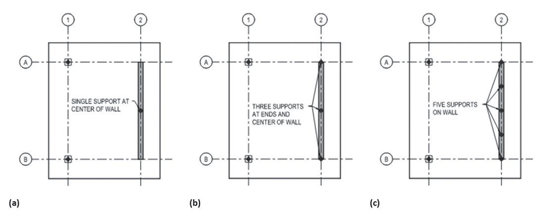
After generating the minimum length support lines, the perpendicular bisectors can be
constructed, and the circumcenter determined for each triangular support region (Figure 3e). For perimeter support lines, no triangle exists. In these cases, the perpendicular bisectors are extended until they hit the edge of the slab/floor under consideration. After constructing the bisectors, tributary areas can be traced along the bisectors and slab/floor edges to form the tributary area polygon for each support (Figure 3f). The areas of these regions are reported in most CAD software packages. They can also be calculated using various geometry and calculus techniques; however, this is beyond the scope of this article.
In common rectilinear grid systems, the lengths of the diagonal lines (hypotenuses) equal each other (Figures 5a and 5b). To deal with this, the engineer simply chooses the line they want to keep and removes the other. The solution does not change and yields the same tributary areas (Figures 5a and 5b).
For rare column layouts, selecting the smallest length support line does not produce the correct tributary area. This can be demonstrated in Figures 6a and 6d, where L1,4<L2,3 The perpendicular bisectors are constructed; however, overlap occurs on the perpendicular bisector, which produces overlap in the tributary areas (Figure 6b). This phenomenon can be explained using Delaunay triangulation, which is beyond the scope of this graphical method (Delaunay, 1934). To address this, the engineer has two options, redraw the larger support line with length L2,3 and delete the shorter
length line L1,4, and then proceed as described above (Figure 6d, e, and f), or construct a modified perimeter line that connects the vertices that are adjacent to the overlap vertices within the overlap polygon region (Figures 6a, b, and c). Figures 6c and 6f show that both approaches produce the exact same tributary area.

Transfer elements are becoming more common as architects push the boundaries of open floor plans with fewer columns. However, given the criticalness of transfer elements, the engineer may choose not to use live load reduction to design supporting columns. If one does choose to use LLR, this method provides a simple way to determine tributary areas.
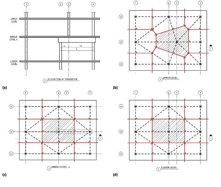
Figure 7 shows a building of n levels with a typical transfer element at some level k, where a column line at grid B-3 shifts laterally to a different location at grid B-2 within the structure. When this occurs, the tributary load from above is now split between two columns (B-2 and B-4). In computing the amount of tributary area to each respective column line supporting the transfer girder, one simply needs to use the ratio of the location of the supported (upper) column with respect
to each supporting (lower) column. In mathematical terms, the total tributary areas AT,column(grid),j for each respective column supporting the transfer element at some lower level j below the transfer level k can be calculated as follows:


where At,column(grid),i is the tributary area to a column at the ith level. The tributary areas can be constructed for each level using the same techniques as presented above.
Live load reduction is an important technique for reducing column sizes in mid to high-rise buildings. ASCE 7 provides a method using the tributary areas for columns to determine the appropriate reduction. However, determining the tributary areas is difficult for complex structural layouts. This article presents a systematic approach for determining the tributary areas for buildings with irregular geometries (slab shapes and column layouts), walls, and transfer levels for determining the live load reduction for columns. The method can be done graphically and is easily implemented within a structural engineer’s design workflow.■

Full references are included in the online version of the article at STRUCTUREmag.org.
Corey D. Casey, P.E. is a professional engineer with Martin/Martin, Inc. in Lakewood, Colorado, where he has been involved in various design projects, including tall PT slab structures.(ccasey@ martinmartin.com)
Phone: 407-284-9202
Email: support@asdipsoft.com
Web: www.asdipsoft.com
Product: ASDIP SUITE
Description: Our software includes the design of beams, columns, walls, base plates, anchor rods, shear lugs, retaining walls, moment connections and more, per the latest design codes. For over 30 years, we have developed powerful yet simple-to-use tools to easily analyze, design, optimize and check your structural members.
Phone: 888-681-8786
Email: info@castconnex.com
Web: www.castconnex.com
Product: Standardized Cast Steel Connectors and Custom Cast Steel Connectors
Description: The industry leader in the architectural and structural use of cast steel components in the design and construction of building and bridge structures. Our products include pre-engineered connectors that simplify the design and enhance the performance of structures. We also offer design-build services for custom cast steel nodes and components.
Phone: 800-424-2252
Email: info@enercalc.com

Web: https://enercalc.com
Product: ENERCALC SEL / ENERCALC 3D
Description: Designing tall buildings in complex systemic design software? Sure. Using that same software for spot checks? Not so fast - literally. Tall buildings have thousands of component elements requiring the development of component / cladding wind loads, and code checks that systemic design software doesn’t often support. ENERCALC does this.
Phone: 260-969-3500
Email: sales@newmill.com
Web: www.newmill.com
Product: Steel Joists and Deck
Description: Achieve architectural visions. Solve engineering challenges. Realize project goals. Your success begins with the selection of the right steel building system. We have the expertise to help you determine the optimal structural steel building system for your application. From steel joists and deck to long-span composite floor systems, we engineer and manufacture solutions that control costs, enhance performance and ensure project success. Together, let’s build it better.
Phone: 510-275-4750
Email: sales@postensoft.com
Web: www.postensoft.com
Product: POSTEN
Description: The Most Efficient & Comprehensive Post-tensioned Concrete Software in the world that, unlike other software, not only AUTOMATICALLY Designs the Tendons, Drapes, as well as Columns, but also produces Highly Efficient, Cost Saving, Sustainable Designs with Automatic Documentation of Material Savings for LEED. The others simply Analyze; POSTEN DESIGNS.
Phone: 949-951-5815
Email: benf@risa.com
Web: risa.com
Product: RISA Floor & RISA-3D
Description: RISAFloor and RISA-3D form an unrivaled multistory building analysis and design package. Modeling has never been easier whether you’re doing a graphical layout, importing a BIM model (from Autodesk Revit), or prefer spreadsheets. Full code checks and optimization for six different material types makes RISA your first choice in buildings.
Part 1: Section Analysis (STRUCTURE, April 2023) presented a general framework for flexural analysis of singly reinforced and doubly reinforced beam sections. In this Part 2: Section Design, flexural design of singly reinforced and doubly reinforced beam sections is studied. The focus is on general sections instead of rectangular sections only. Although it may be adequate to design beam sections using a trial-anderror approach based on the section analysis steps outlined in Part 1, the design approach presented in this article determines the minimum required steel area to support a given factored bending moment. For symbols not defined in this article, please refer to the American Concrete Institute’s ACI 318-19, Building Code Requirements for Structural Concrete.


The well-established analysis and design method of rectangular sections is the building block of the design of more complex cross-sections. The design moment strength of a rectangular section is
ACI 318-19
The trade-off concept of the reinforcement ratio and the concrete section size can be seen in Figure 2. To provide the same moment strength in Eq. (1), the maximum reinforcement requirement (ACI 318-19: 9.3.3.1) corresponds to the smallest required concrete section, whereas the minimum reinforcement limit (ACI 318-19: 9.6.1.2) corresponds to the largest concrete section. Therefore, the ACI 318-19 range of reinforcement ratio (��max − ��min) can be used to determine the range of concrete section size ((b, d )min − (b,d )max). For practical design purposes, a concrete section size in the range shall be selected to design the section to support the required moment strength while meeting the ACI reinforcement requirements. If a design ends up being a transition section (��y < ��t < ��y + 0.003) rather than a tensioncontrolled section, it is clear that the concrete section size (b, d ) is too small, and a larger section size shall be provided to ensure the design is in the range.
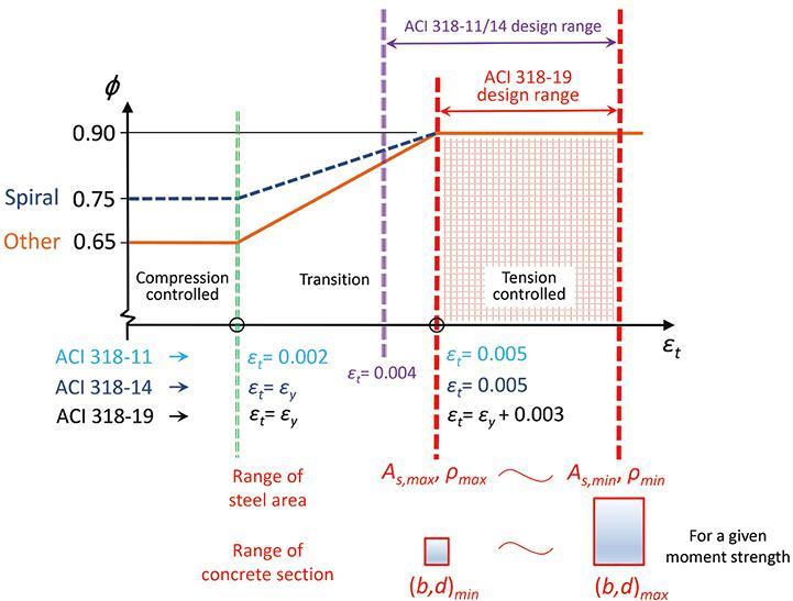
Figure 1 shows the relationship between ��, Rn , and section size (b, d ). To start the design with a given concrete section size (b, d ), the calculation is carried out from right to left, and Rn ⟶ �� is needed to determine the required steel area. If a target reinforcement ratio is adopted to start the design, the computation is performed from left to right and �� ⟶ Rn is required to determine a concrete section size (b, d ).
One straightforward method for designing complex singly reinforced or doubly reinforced concrete beam sections is to separate the beam section into multiple sections and add their moment strengths together. Tension steel is assumed to yield for design purposes.
For a singly reinforced non-rectangular beam section, the design flexural strength can be determined based on breaking down the equivalent concrete compression zone, Ac, into multiple smaller areas (such as rectangles) and adding their design strengths, as ��Mn = ∑��Mn (4)
As a simple example, Figure 3 shows two cases of a T-beam. The design of a Case 1 T-beam is essentially the same as the design of a rectangular section (Rn ⟶ ��). For a Case 2 T-beam, the total flexural strength can be written by adding the strength provided by the flange (Beam 1, with steel area Asf ) and the web (Beam 2, with steel area Asw ), as ��Mn = ��Mnf + ��Mnw (5)
Once the moment strength of the flange, ��Mnf , is determined, the leftover factored moment shall be supported by the web and used to design the web as a rectangular section (Rnw ⟶ ��w). Rnw and ��w are the flexural-resistance factor and reinforcement ratio of the web, respectively.
The same concept can be applied to more complex cross-sections, and different design cases may be possible. Some more examples are shown in Figure 4. Some detailed calculations are needed to determine which case is required for the given factored moment. Figure 5 details how to decide the three possible design cases of a beam section with a void and how to further separate the beam section into multiple sections (2 or 3 beam sections in this example). A Case 2 beam here is similar to a Case 2 T-beam mentioned before, so that As = Asf 1 + Asw and ��Mn = ��Mnf 1 + ��Mnw. For a Case 3 beam in this example, the total required steel area and design moment strength are As = Asf 1 + Asf 2 + Asw and ��Mn = ��Mnf 1 + ��Mnf 2 + ��Mnw , respectively. An alternative way to design a Case 3 beam is to use As = Asw − Asf 3 and ��Mn = ��Mnw − ��Mnf 3, where Asf 3 and ��Mnf 3 are the steel area and design moment strength, respectively, corresponding to the void (minus for negative values). Dividing the equivalent concrete compression zone into multiple areas is a general approach and is easily applicable as long as the web (Asw and ��Mnw) can be designed as a rectangular section (Rnw ⟶ ��w).
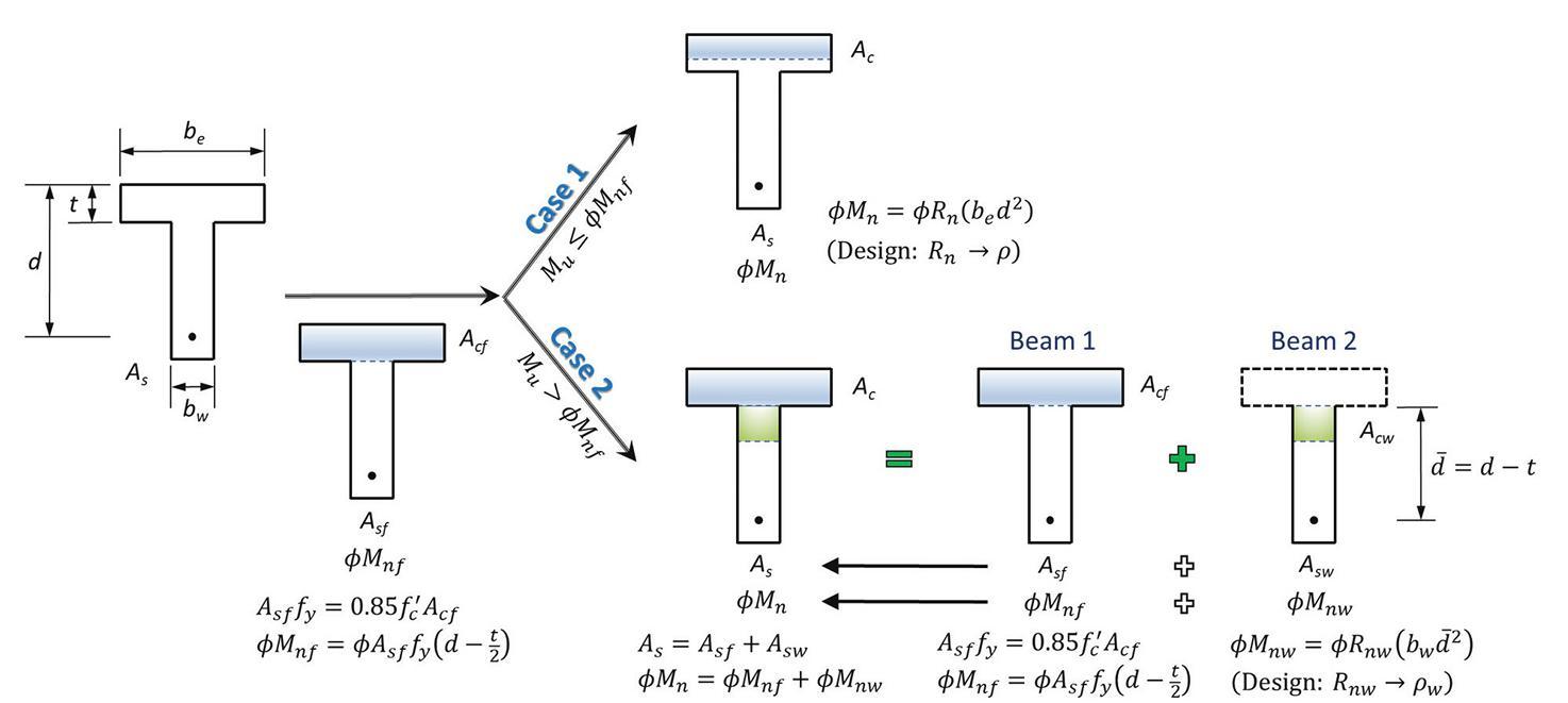

Figure 6 illustrates separating a doubly reinforced beam section into two beam sections. If the upper bound (maximum) design moment strength of a singly reinforced beam section (��Mn1 = ��Mn,max) is still not adequate to support the factored moment, Mu, a doubly reinforced beam section becomes necessary (for the same section size). The maximum area of reinforcement, As,max , permitted by ACI 318-19 for a singly reinforced beam section is determined first using ��t,min = ��y + 0.003 before the
maximum moment strength can be calculated. This is noted as Beam 1. A backward analysis is required here and applies to any cross-sectional shape. The leftover factored moment has to be supported by Beam 2, which is provided by the couple of additional tension and compression steel (As2 & A' s ). Although it is acceptable to design a doubly reinforced beam section targeting a strain value greater than ��t,min , the design using ��t,min would result in the least total area of steel in the section.

For a given beam section, the design procedure includes the following steps:
1.Perform a backward analysis (see Part 1: Section Analysis) to determine the maximum area of reinforcement, As,max, allowed in a singly reinforced beam section
��t,min = ��y + 0.003 ⟶ c (neutral axis) ⟶ α = ��1 c ⟶ Ac (shape) ⟶ As,max =
2. Determine the maximum design moment strength, ��Mn,max (or ��Mn1), when As,max is used in the beam section y (shape) ⟶ Mn,max ⟶ �� ⟶ �� Mn,max

3. Determine the design of a singly reinforced or doubly reinforced section. If Mu ≤ ��Mn,max, design the section as a singly reinforced concrete section; proceed with steps 4a-8a. If Mu > ��Mn,max), design a doubly reinforced beam section. Determine the leftover moment, Mu2 = Mu − ��Mn,max, and proceed with steps 4b-8b.
4a.For a singly reinforced beam section, determine the moment resistance of the flange


5a.Determine the design case of a singly reinforced beam section. If Mu ≤ ��Mnf , design the section as a Case 1 beam. This is essentially the design of a rectangular section with b = be .
Rn = ⟶ �� ⟶ As = �� be d ⟶ select bars and perform a final check.

If Mu > ��Mnf , design a Case 2 beam. Calculate the leftover moment, Muw = Mu − ��Mnf , and proceed with steps 6a-8a.


6a.Design the web as a rectangular section, i.e., b = bw, and d is the distance from the centroid of the tension steel group to the extreme concrete compression fiber in the web. R


7a.Calculate the total steel area for flange and web, As = Asf + Asw


8a. Select rebars and perform a final check. Here steps 4a-8a are written assuming a Case 2 beam. Similar steps can be followed for a more complex case (e.g., Case 3).

4b.Check whether the compression steel yields. Calculate
5b.For Beam 2

6b.Calculate compression steel area in Beam 2
and check whether this is greater than or equal to the yield strain of steel, ��y . Calculate the compression steel stress


(does not yield) or fy (yield)



7b.Compute total tension steel area As = As1 (As,max) + As2 (12) and total compression steel area A' s (in step 6b).
8b. Select tension and compression rebars, and perform a final check.■
References and a numerical example are included in the online version of the article at STRUCTUREmag.org.

Qian Wang is an Associate Professor in the Department of Civil and Environmental Engineering at Manhattan College, Riverdale, NY (qian.wang@ manhattan.edu).
Shahriar Quayyum is a visiting Assistant Professor in the Department of Civil and Environmental Engineering at Manhattan College, Riverdale, NY.

Given a beam section, as shown in Figure 7, use f' c = 3,000 pounds per square inch (psi) and Grade 60 rebars (fy = 60 kips per square inch [ksi]). Determine the minimum required steel areas to support the following factored bending moments and select rebars.
a. Mu = 120 kips − feet (k − ft.);
b. Mu = 220 k − ft;
c. Mu = 280 k − ft.
Bending Moment, Mu = 120 k − ft
1. Perform a backward analysis (detailed calculations are skipped here; see the numerical example in Part 1: Section Analysis in a previous issue of Structure Magazine) to find the neutral axis depth, c, and determine As,max for a singly reinforced beam section.
c = 7.875 inches (in)
As,max = 3.08 square inches (in2)

2. The maximum design moment strength
��Mn,max = 241 k − ft
3. Since Mu = 120 k − ft < ��Mn,max = 241 k − ft, design the section as a singly reinforced concrete section.
4a. For a singly reinforced beam section, determine the moment resistance of the flange

Asf = = 2.55 in2
��Mnf = �� = 0.9 × 2.55 in2 × 60 ksi × in = 2,478.6 kips − inches (k − in) = 206.55 k − ft
5a. Since Mu = 120 k − ft < ��Mnf = 206.55 k − ft, design the section as a Case 1 beam (a rectangular beam section with b = be = 10 in).
Rn = = 0.3628 ksi
�� = = 0.00655
As = ��be d = 0.00655 × 10 in × 21 in = 1.38 in2

This is the minimum required steel area to support the factored moment. Select 5 #5 bars in one row; As = 0.31 × 5 = 1.55 in2, in the range of steel area permitted by ACI 318-19 for a singly reinforced beam section (1.26 in2 – 3.08 in2).
8 steps of forward analysis as introduced in Part 1: Section Analysis of the article are conducted to perform a final design check. It is confirmed to be a tension-controlled section (�� = 0.9), and ��Mn = 134 k − ft > Mu = 120 k − ft. Strength is ok.
Bending Moment, Mu = 220 k − ft
3. Since Mu = 220 k − ft < ��Mn,max = 241 k − ft, design the section as a singly reinforced concrete section.
5a. Since Mu = 220 k − ft > ��Mnf = 206.55 k − ft, design the section as a Case 2 beam by separating the beam section into 2 sections. Leftover moment Muw = Mu − ��Mnf = 220 − 206.55 = 13.45 k − ft
6a. Design the web as a rectangular section with b = bw = 18 in and d = d − t = 21 − 6 = 15 in Rnw = = 0.04428 ksi
= 0.0007445
Asw = ��wbwd = 0.0007445 × 18 in × 15 in = 0.20 in2


7a. Total steel area for flange and web, As = Asf + Asw = 2.55 + 0.20 = 2.75 in2
This is the minimum required steel area to support the factored moment.
8a. Select 5 #7 bars in one row; As = 0.6 × 5 = 3.0 in2, in the range of steel area permitted by ACI 318-19 for a singly reinforced beam section (1.26 in2 – 3.08 in2).
8 steps of forward analysis are conducted (see Part 1: Section Analysis) to perform a final design check. It is confirmed to be a tension-controlled section (�� = 0.9), and ��Mn = 236 k − ft > Mu = 220 k − ft. Strength is ok.
Bending Moment, Mu = 280 k − ft
3. Since Mu = 280 k − ft > ��Mn,max = 241 k − ft, design the section as a doubly reinforced concrete section. Leftover moment Mu2 = Mu − ��Mn,max = 290 − 241 = 39 k − ft
4b.Check whether the compression steel yields
�� ' s = = 0.001857 < ��y = 0.00207 does not yield

Compression steel stress
f' s = Es �� ' s = 29,000 ksi × 0.001857 = 53.86 ksi
5b.For Beam 2
Mu2 = ��[As2 fy (d − d' )]


Tension steel area in Beam 2
As2 = = 0.48 in2
6b.Compression steel area in Beam 2
A' s = = 0.54 in2
7b.Total tension steel area
As = As1 (As,max) + As2 = 3.08 + 0.48 = 3.56 in2
Total compression steel area A' s = 0.54 in2
8b.Select rebars
tension 6 #7 bars in one row, As = 0.6 × 6 = 3.6 in2
compression 2 #5 bars in one row, A' s = 0.31 × 2 = 0.62 in2
12 steps of forward analysis are conducted (see Part 1: Section Analysis) to perform a final design check. It is confirmed to be a tension-controlled section (�� = 0.9), and ��Mn =284 k − ft > Mu = 280 k − ft. Strength is ok.
1. Although, in practice, structural engineers can use approximations to design beam sections (for example, a box section is approximated as a rectangular section), the design is handled on a case-by-case basis. A general framework for the design of singly reinforced and doubly reinforced concrete beam sections is presented in this article. The approach is rigorously derived and is used to find the minimum required steel area to support a given factored bending moment.
2. Separating the equivalent concrete compression zone into multiple smaller areas is very useful and can be applied to more complex cross-sections.
3. The backward analysis to determine the maximum steel area and bending moment strength of a singly reinforced beam section permitted by ACI 318-19 helps design doubly reinforced beam sections.
4. This article is supplementary material to any reinforced concrete textbook to understand the topic better.




Ultrasonic testing use to ensure the safety and reliability of our bridges.

 By Mike Januszkiewicz, P.E.
When doctors need to diagnose an internal medical issue, they use an X-ray machine or ultrasonic testing to non-invasively look inside the human body. When it comes to checking the potentially ailing components of a bridge, the engineers can use ultrasonic testing (UT), a non-destructive testing (NDT) method, to look inside the bridge. This allows them to view and understand a bridge’s welds and components for structural integrity before deterioration or internal flaws become a potential hazard.
Ultrasonic testing is a non-invasive testing practice that is widely used for evaluating the integrity and condition of bridge pins, gusset plates, and welds. Pins, gusset plates, and welds are critical components of any bridge as they are responsible for transferring loads from one member to another and helping to stabilize the entire structure. This article primarily addresses the UT inspection of bridge pins, as UT inspections of welds is relatively straightforward (generally following ASNT, or AWS D1.1 or D1.5), whereas UT inspection of bridge pins is not as clear (generally following the guidelines of FHWA HRT 04-042). Using a transducer (transmitting and receiving highfrequency sound), UT employs a mechanically induced sound wave to inspect the material properties of these components in order to identify any weaknesses, defects, wear, or flaws that could compromise the safety of the bridge. Findings may include internal cracks, internal inclusions, hidden surface wear, and other types of defects that may not be visible to the naked eye.
Once detected, the findings must be evaluated to determine the potential severity of each identified issue.
One of the main advantages of ultrasonic testing is that it allows engineers to examine the internal and hidden external areas relatively quickly and efficiently with minimal disruption to the bridge’s operations for its public users. Engineers can then identify and monitor advancing issues or direct repairs in an efficient and accurate manner.
transducer. The machine transmits high-frequency sound waves into the material being tested. When the sound waves encounter a discontinuity (flaw or boundary) in the material, they are reflected back to the transducer. The flaw detector processes the time of outgoing and reflected sound waves into an electrical signal displayed on a screen for the operator to interpret. The UT flaw detection equipment measures the time between the outgoing and incoming signals and converts the time into a “distance” by means of machine settings or calibration settings. In this way, a flaw detector machine can be thought of as a “fancy stopwatch” that converts time into distance through specific machine settings. The calibration settings of the machine will greatly affect the accuracy of the results read on the operator’s screen.
UT inspection of bridge pins uses very precise UT flaw detection equipment to examine an inexact medium (bridge components) under field conditions. For example, all boundary surfaces are neither truly flat nor uniformly smooth, and reflective surfaces can be at a variety of sizes and angles. A qualified UT technician is capable of using the transducer to measure bridge pin length and distance to reflectors with incredible accuracy, provided reflector conditions are precise. To ensure the results are accurate, there is a requirement of proper calibration settings and reflectors perfectly perpendicular to the direction of the sound waves, as well as an experienced UT technician to interpret the findings. This is why it is important for the operator to thoroughly understand what they are examining. In the case of bridge pins, the types of pins (straight or shouldered) on a particular bridge can affect what the operator will see on their screen. The geometry of bridge pins varies and dictates which transducer(s) must be used during the process. Geometric oddities in the pin could be misinterpreted if improperly read, which could result in a compromised report, or at the very least, frustration for all involved. There is almost as much art as there is science when it comes to the interpretation of UT results; thus, it is important to have an experienced individual perform the UT.
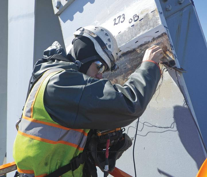
Although ultrasonic testing is a complex process as it involves a deep understanding of several factors from engineering to physics, it can be considered as a learned art. The “art” is found in the interpretation of return signals—a skill gained through an understanding of UT sound wave propagation, a foreknowledge of what might be observed based on pin geometry, personal experience, and even the history of the bridge. The UT operator must pay close attention to the dynamics of return signals and document the test through detailed data sheets to be used for later comparisons.
A good UT inspection is also not complete without proper documentation. Documentation should include data sheets, sketches, and saved versions of pertinent screenshots (A-scans). The dynamic and A-scan return signals obtained during a bridge pin inspection are what help engineers evaluate the UT operator’s interpretation. It also allows other UT technicians to be able to relocate the indications for verification and comparative analysis. An often glossed-over component, documentation is critical to a successful inspection.
A successful UT inspection was performed on a steel truss bridge constructed in 1909 across the Mississippi River, designed by Modjeski and Masters. During a detailed inspection in 2007, 204 truss joint/hanger pins were evaluated with findings of surface corrosion, wear grooves, and gaps observed within the hanger pin assemblies. Ultrasonic testing revealed

discontinuities of varying degrees in most of the pins, including verification of visible wear grooves, identification of hidden wear grooves, areas of hidden corrosion, and identification of internal flaws (likely present from the pin formation process). 28 of the 204 pins were found to have significant ultrasonic indications (warranting future monitoring), and three were found to have surface flaws. The non-invasive nature of UT allowed the technicians or the engineers to diagnose potential issues and flaws before they compromised the structure and became a danger to the public.
Ultrasonic testing can be conducted using several different techniques, each of which is suited to different types of structures and applications. The most common method used for bridge pins is pulse-echo testing, which involves sending a pulse of ultrasonic energy through the material and measuring the time it takes for the pulse to reflect back. The speed of the pulse and the time it takes to return can be used to calculate the thickness and density of the material, as well as to identify any flaws or defects that may be present. Pulse-echo testing is relatively simple and can be used on a wide range of materials, including metals, plastics, and ceramics.
Through-transmission testing is another method where ultrasonic energy is transmitted through one side of the material and received on the other side, and the intensity of the energy that passes through the material is measured. This method is particularly useful for dense or multi-layered materials as it allows engineers to examine the entire thickness of the material.
Time-of-flight diffraction (TOFD) is a specialized method that involves sending ultrasonic energy through the material
and measuring the time it takes for low amplitude energy to defract (bend around) any flaws or defects that may be present. The full potential of TOFD for characterizing defects can only be realized if the amplitude and phase of the defracted ultrasound can be reliably interpreted. TOFD is particularly useful for detecting the ends of cracks and other types of defects that may be difficult to identify using other testing methods. In addition to these techniques, there are also several other specialized methods that can be used for more specific applications. For example, phased array ultrasonic testing involves using multiple ultrasonic transducers simultaneously to create a two-dimensional image of the material being tested, which can be used to more accurately locate and characterize defects. Other specialized techniques include laser ultrasonic testing, which uses laser pulses instead of sound waves, and thermoelastic stress analysis, which involves measuring temperature changes in the material to identify stress concentrations.
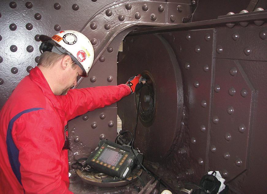
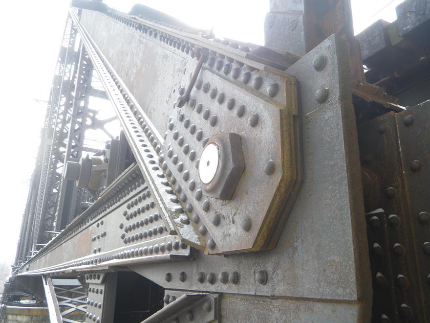
One of the challenges of ultrasonic testing is that it requires specialized equipment and trained and experienced technicians to carry out the inspection process. This means that it may not always be practical or cost-effective to use ultrasonic testing as the primary method of evaluating structural integrity; however, for firms or organizations that have access to the resources and expertise to carry out proper ultrasonic testing, it can be an invaluable tool for ensuring the safety and reliability of bridge components.
Another challenge with ultrasonic testing is the orientation of discontinuities and surface boundaries. Ultrasonic testing is most effective at detecting reflectors that are perpendicular to the direction of the sound waves. Discontinuities
that are oriented parallel to the sound waves may be more difficult to detect. Angular discontinuities can deflect sound and may require changes in the type of transducer used.
Temperature can also be a challenge during an inspection. Interestingly, the speed of sound waves can change with temperature. This can affect the accuracy of a UT inspection given that it relies on these waves for an accurate reading. If the temperature poses an issue, the UT operator may need to change the frequency used to push sound through the component. This creates more beam spread, which picks up more area than desired and reduces the clarity and detail of the inspection.
There are several levels of certification available to those who are interested in performing ultrasonic testing in their work. These levels are recognized internationally and defined in the United States by the American Society for Nondestructive Testing (ASNT).
•Level I is the entry-level certification for UT technicians. It allows the individual to set up and calibrate equipment, perform basic UT examinations, and prepare reports under the supervision of a Level II or Level III technician.
•A Level II technician is able to independently set up and calibrate equipment, perform basic and advanced UT examinations, prepare reports, and provide guidance to Level I technicians under a specific procedure approved by a Level III technician.
•A Level III technician is able to perform all tasks of a Level II technician, as well as develop and implement UT procedures, select and justify the use of UT techniques, and provide guidance to Level I and Level II technicians. When selecting an inspector for the job, bridge owners should carefully consider the experience and qualifications of a technician, as well as their certification level. It’s possible for an individual to be certified in UT but not be prepared to thoroughly and accurately inspect all types of bridge pins. Experience is key—training and certifications do not replace a UT technician versed in examining the intricacy of bridge pins and their unique properties.
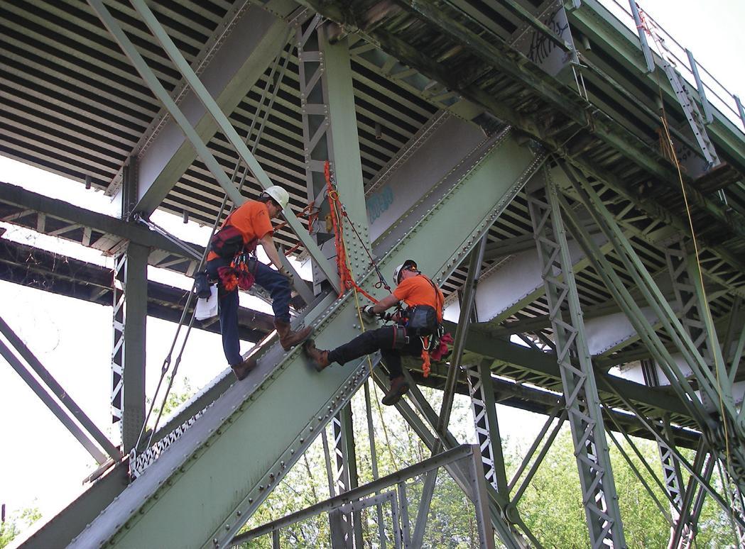
There are several trends and developments that are shaping the future of ultrasonic testing and helping the field evolve. Artificial intelligence (AI) is one of the ways machine learning is being used to improve the accuracy and efficiency of UT. For example, AI algorithms can be used to analyze large amounts of test data and identify patterns that may indicate the presence of defects. They can also be used to optimize testing parameters and improve the reliability of test results.
Another developing trend is 3D imaging. It is the process in
which one can generate 3D images of the material being tested. These images can provide more detailed and accurate information about the size, shape, and location of defects within the material.
There are developments in no-contact ultrasonic testing methods that do not require the use of a physical transducer to transmit ultrasonic waves. These methods could be used to test materials or components that are sensitive to physical contact or to test structures that are too large or complex to be tested with traditional UT methods. Researchers are also working on the development of wireless UT systems, which could be used to test structures or components in hard-to-reach or hazardous locations. These systems would use wireless sensors and communication technologies to transmit test data remotely. Acoustic emission testing is a related technique that involves detecting and analyzing the sounds generated by defects or material failures. Researchers are working on integrating acoustic emission testing with UT to provide a more comprehensive understanding of the condition of a material or component. At this time, extensive calibration is required.
Since its inception more than 80 years ago, ultrasonic testing remains the most valuable and reliable tool for evaluating the condition of bridge pins, welds, and gusset plates. With the depth of knowledge that goes into the inspection of these vital components—along with the promising future of technology and its role in engineering—ultrasonic testing continues to minimize the risk of failure and ensure the safety and reliability of our everyday bridges.■
Mike Januszkiewicz P.E. is a Senior Project Manager at Modjeski and Masters. He coordinates NDT services, is a Safety Coordinator, and oversees the Technical & Rope Access Program. He has experience in bridge design, construction inspection, load rating, and NBIS condition inspection. Additionally, he is a Technical & Rope Access Climbing Instructor, and is certified in various non-destructive testing methods, including dye-penetrant, magneticparticle, and ultrasonic material testing. He has inspected over 2,000 bridge pins and multiple welds ultrasonically as a Level 2 UT Pin and Weld Inspector.
 By Jessica Mederson, Partner, Stafford Rosenbaum LLP and Mónika Serrano, Resilience Program Manager, Turner Construction Company
Flooding, heat waves, rising sea levels, and the associated news about these effects of climate change are enough to make anyone feel hopeless about what can be done. The National Oceanic and Atmospheric Administration (NOAA) estimates that Americans experienced twenty separate multi-billion-dollar weather and climate disasters in 2021 alone, costing $145 billion. Last year, Hurricane Ian—estimated to be the costliest Florida storm since Hurricane Andrew—had storm surge losses estimated to cost between $28 and $47 billion. One industry, however, is poised to make a profound positive impact in the face of this dire news: engineers. Engineers have the knowledge and the skillset to reduce the risk that their projects will face climate-change-related risks if they incorporate the three basic steps below into their project work.
Engineers are at the forefront of recognizing and understanding the threats posed by climate change and the changes that need to happen in the design and construction processes. The World Federation of Engineering Organizations (WFEO) has issued a Declaration on Climate Emergency, stating “The crises of climate breakdown are the most serious issues of our time. Our major infrastructure systems of transport, energy, water, waste, telecommunications, and flood defenses play a major part, accounting for a vast portion of energy-related carbon dioxide (CO2) emissions while also having a significant impact on our natural habitats.” As a result, the WFEO has pledged, among other things, to “apply, and further develop, climate mitigation and adaptation principles as key measures of our industry’s success demonstrated through rating systems, awards, prizes, and listings.”
“Extreme event attribution” is the science linking extreme weather events to climate change. This field has developed over the past two decades with increasingly standardized methodologies and extensive published literature. Climate change influences the intensity, frequency, and length of weather events. The American Meteorological Society (AMS) researches the attribution of weather events to climate change and publishes an annual review of extreme events and their connection to climate change. The AMS’s latest report confirms that extreme weather events are driven by climate change and that the risks are increasing. While extreme heat, drought, and other extreme weather events are gaining attention, rising water levels are the most pressing climate change risk facing many communities today.
Global sea level has risen approximately 6.7 inches in the past century, with regional sea level rise being more or less than that average, depending on several factors. In parts of the US Northeast, sea levels have already risen by 16 inches, which is expected to continue. And inland areas are not immune from climate-change-related water damage. The Third National Climate Assessment reported that rainfall events have become heavier and more frequent. The increase in rainfall has been most significant in the Northeast, Midwest, and Upper Great Plains—with increased flooding in those same areas. Inland flooding is estimated to be the most costly of severe weather events, with an annual average price tag of $6.9 billion.
Combine those more intense rainfalls with the non-permeable surfaces that characterize modern towns and cities, and we see increased flooding. Urban flooding, with its unique challenges and high stakes, is a pervasive problem, with an urban flooding event occurring at a rate of once every two to three days over the past 25 years.
So what do these challenges mean to engineers who frequently look to building codes to set the minimum life-safety design requirements? Most building codes have not yet been written to address the consequences of climate change, mainly because codes are based on historical climate data instead of future climate estimates. Two years ago, the Federal Emergency Management Agency (FEMA) surveyed the nation’s building codes, finding that $1.6 billion in losses had been avoided since 2000 thanks to buildings designed following more stringent building codes, yet 65% of municipalities in the U.S. have not yet adopted them.
At the same time, FEMA’s flood maps can be seriously out of date, as Professor Gerrard, founder, and faculty director of the Sabin Center for Climate Change Law, has noted: “They reflect only historical conditions, not future flooding as a result of sea level rise and extreme precipitation.”
Not only are the flood maps outdated, but over 40% of the United States has not been mapped. In 2020, scientists working with the First Street Foundation, a non-profit research and technology group dedicated to quantifying and communicating climate risks, identified 6 million more Americans living in areas with a substantial risk of flooding than the 8.7 million properties identified as having such a risk by FEMA.
Until there are binding government requirements, it is up to engineers
and architects to understand the climate change risks that projects face and plan with future climate estimates in mind, incorporating resilience above and beyond what current building codes require. Fortunately, resilience strategies already exist and are simple. A few examples include designing thicker building envelopes to deal with extreme heat, incorporating power and water redundancy to better deal with utility interruptions, and planning for egress and ingress to the building in severe water events. “During the design phase, the expected lifetime of a structure should be determined, at least 50 years, but 100 years is a more reasonable approach. Then, local sea level rise projections need to be taken into account,” suggests Dr. Klaus Jacob, a geophysicist and emeritus research professor at Columbia University’s Lamont-Doherty Earth Observatory. For example, Dr. Jacob recommends that builders “elevate all critical equipment and locate all water-sensitive materials on top of the building.” Saltwater poses its unique challenges, corroding materials such as concrete and rebar, thereby reducing the safe life of a project.
Fortunately, more resources are becoming available every day to assist engineers with identifying local issues and incorporating resilience into their designs. For example, the Intergovernmental Panel on Climate Change (IPCC) introduced at COP27 the Global Building Resilience Guidelines. COP, short for “Conference of the Parties,” is an international climate meeting held each year by those countries that have joined the United Nations Framework Convention on Climate Change (UNFCC), which includes the US. Parties to the treaty have committed to take voluntary actions to prevent “dangerous anthropogenic [human-caused] interference with the climate system.” COP27 is the 27th climate meeting since the UNFCC treaty was negotiated in 1992.
FEMA also provides extensive hazard-specific guidance that focuses on creating hazard-resistant communities. Future climate modeling is also a growing industry, with numerous resources available. Finally, to ensure that all parties to a construction project understand their roles and responsibilities, engineers should introduce contractual language or documents similar to the American Institute of Architect’s Hazard and Climate Risk form.
Can design professionals be liable if they design only to existing building code requirements? A recent study found that the average value of a construction dispute in North America doubled from 2019 to 2020: jumping from $18.8 million to $37.9 million. This study found that the leading cause of disputes remained the same in 2020 as in 2019: a failure by the parties to the construction relationship (owner, contractor, architect, engineer, etc.) to understand and/or comply with their contractual obligations. When designing buildings in the face of climate change, engineers must ask whether they are fulfilling their professional standard of care. Engineers are obligated to provide services to their clients with the degree of skill and care that would be exercised by other professionals in their industry, taking into consideration the contemporary state of the art and the region in which the professional practices. Failure to exercise that standard of care can expose engineers to legal liability. However, engineers’ standard of care is not static, as it “changes over time based on research, development, and new information.” City of Huntington v. AmerisourceBergen Drug Corp., 2022 WL 2399876, at *37 (S.D.W. Va. July 4, 2022).
The challenge for engineers, therefore, is to define the expectations under the “contemporary state of the art.” As Susanne DesRoches, Vice President of Clean and Resilient Buildings at the New York State Energy Research and Development Authority, notes, a question all engineers (and architects) must ask themselves is: “What is your legal obligation to advise your clients about future climate risks?”
Given the documented risks of extreme weather, the increase in such extreme weather, awareness in the engineering community about the risks of climate change, and the evidence that many building codes are not equipped to deal with all aspects of climate change, judges and juries may soon find that architects and engineers who design to current code provisions are not complying with the standard of care. As Randy Lewis, Vice President, Loss Prevention and Client Education for AXA XL’s Design Professional Group, points out, “Under some circumstances, merely designing to meet code requirements may still be deemed negligent if the circumstances and the applicable standard of care dictate a design solution that exceeds the code.”
Depending on the region in which a project is being built, there can be a wealth of information about the risks a project can face from climate change. First Street Foundation, for example, provides resources on various risks, including wildfires, floods, and heat. First Street Foundation has a free Risk Factor platform for non-commercial properties that the Federal government has used. Other modeling resources available include the Climate Mapping for Resilience and Adaptation tool, which was developed in August 2022 as part of an interagency partnership working under the auspices of the U.S. Global Change Research Program (USGCRP), with guidance from the U.S. Federal Geographic Data Committee (FGDC), and is designed to work with the U.S. Climate Resilience Toolkit. Climate Check and Jupiter Intelligence are other examples of available climate modeling resources. The American Society of Civil Engineers also recently published an overview of applying global climate model projections in infrastructure engineering, which walks through applying climate model projections in engineering.
While some developers may hesitate to add costs to a project to address climate risk, engineers can use the existing data to explain to their clients that the significant trends caused by climate change justify initial costs associated with resilience efforts, which provide consequential benefits such as business continuity, minimized building repairs, occupant safety, and comfort, reputation, and litigation avoidance. The Natural Hazard Mitigation Saves: 2019 Report, a multi-disciplinary, multi-decade study funded by the United States Housing and Urban Development and released by the National Institute of Building Sciences, provides cost-benefit analyses that can be used to demonstrate to the client the benefits of adopting and/ or exceeding current codes to address climate change issues.
As extreme weather becomes more prevalent, engineers must protect their clients and their bottom line by ensuring that their clients and designs incorporate resilience into their projects. With all the available data and resources today, it is unwise not to pay attention to climate change, adaptation, and resilience during the design phase. This increases the likelihood that a judge or a jury may force you to pay attention to climate change in the future.■
Full references are included in the online version of the article at STRUCTUREmag.org.
The largest projects are built with vision. Support yours with Jumbo HSS from Atlas Tube. Building a warehouse? Factory? Airport hangar? We have you covered with the largest hollow structural sections (HSS) manufactured in North America. Jumbo HSS from Atlas Tube provide more support using less steel due to
their higher strength-to-weight ratios when compared to wide-flange sections. Each section is manufactured using the cleanest steel made in the USA, which reduces the overall embodied carbon in your structure.

Feel confident designing with Jumbo HSS. Frequent rolling schedules and distributors across North America assure availability when your project needs it.

• Squares up to 22" x 1" wall
• Rounds up to 28" OD x 1" wall
• Rectangles up to 34" x 10" x 1" wall
Build bigger with Jumbo HSS atlastube.com/jumbo
According to the World Meteorological Association, 2011-2020 was the warmest decade on record. The current decade is expected to be even warmer. Climate change is real; excess atmospheric carbon is a primary cause, and reducing it is the responsibility of all. That includes structural engineers, who can play a key role in reducing the carbon footprint of buildings and other structures.
The contribution of structural engineers to sustainability can be twofold. The first is by participating in ongoing initiatives to reduce the carbon footprint of structural materials. Structural engineers can play a valuable role in these initiatives by developing an awareness and understanding of new carbon-favorable materials and specifying them when and where feasible. Many new materials and processes that can reduce embodied carbon are incubating around the globe, waiting only for the specifier’s pen to put them in play.
The second, equally important, and more directly controlled contribution of structural engineers to embodied carbon reduction is in creating efficient designs that optimize structural material quantities and allow the productivity potential of modern construction systems to be fully realized. Reducing embodied carbon arguably begins with
a materially efficient design that responds to the realities of construction. Efficient material use plus simplified construction equals carbon reduction. Structural engineers who understand and execute this will lead the sustainability initiative.
This article will discuss several tactics for each of those two strategies for reducing the carbon footprint of structural designs. And since concrete has been a focus of recent sustainability initiatives due to its significant carbon footprint, this article will focus on that material.
Concrete is the world’s most widely used construction material. It is common to all continents and all types of structures. But concrete has a major sustainability problem caused primarily by its cement binder. As limestone is heated to the extreme temperatures required to make cement, a chemical reaction emits significant carbon dioxide as the limestone transforms to clinker. About 7 percent of all excess global atmospheric carbon comes from the cement manufacturing process, making cement a primary target for carbon reduction strategies in the concrete industry.
To reduce embodied carbon in concrete projects, one option is to use Portland Limestone Cement (PLC), a material that’s beginning to dominate U.S. concrete construction. PLC, also known as Type 1- L cement, is a blended hydraulic cement that contains between 5 and 15 percent unheated limestone per ASTM C595. Increasing the unheated limestone and simultaneously reducing cement content offers comparable performance to Portland Cement while reducing PLC’s overall carbon footprint by about 10 percent.
PLC has been successfully specified on several recent projects, including The Ayer in Seattle, a 40-story luxury apartment tower currently completing construction. PLC was used in all primary mixes – foundations, columns, shear walls, and slabs – with specified concrete strengths as high as 15 ksi in lower-level columns. While there were initial difficulties in achieving specified performance, the net result of using PLC was positive throughout.

Interestingly, while PLC is only now gaining a foothold in the U.S., Europe has been experimenting with this more environmentally friendly material for over 40 years. European Standard EN197-1 includes provisions for types of cement containing unheated limestone in amounts up to 35 percent.
Another new cement with even greater sustainability benefit than PLC is Limestone Calcined Clay Cement, also known as LC3. Although its use has been limited, LC3 has big potential for carbon reduction. It combines Ordinary Portland Cement (OPC), limestone, low-grade clays available in abundant quantities, and small amounts of gypsum.
LC3 is cost-effective and does not require modifications to existing production equipment. Strengths achieved with LC3 mixes are equivalent to OPC mixes. Most importantly, from a sustainability perspective, LC3 reduces carbon dioxide emissions by up to 40 percent compared to mixes made with OPC.
The LC3 blend most commonly being studied is LC3-50, meaning that only 50% of the blend is OPC, with the remainder being calcined clay, limestone, and gypsum. This OPC reduction is highly important to the concrete industry’s carbon challenge since it is anticipated that the steadily diminishing availability of fly ash and blast furnace slag for use as Supplementary Cementitious Materials (SCMs) will soon require other strategies for OPC reduction.
Fortuitously, in addition to reducing the need for SCMs, the durability characteristics of LC3 are even better than mixes made with fly ash and slag, creating an opportunity for the industry to reduce its carbon footprint and simultaneously improve structural durability without the use of either of these two pozzolanic materials. LC3 mixes have higher resistance to chloride ion penetration and alkali-silica reactivity, both of which are important qualities for improving the durability of bridges, buildings, and other structures.
LC3 is a product that engineers and specifiers should investigate and ultimately embrace. Since ASTM C595 “Standard Specification for Blended Hydraulic Cements” allows an OPC clinker content as low as 45%, LC3-50 is feasible for use today.
Several alternative pozzolans are entering the market, one of the more interesting being ground glass, a product made from recycled glass. First used in 1998, it is made by feeding waste glass into a
grinding apparatus that feeds into an air classifier. The air classifier separates out oversize particles and sends them back to the hopper for further grinding.
Ground glass added to the concrete as a Supplementary Cementitious Material (SCM) forms a calcium silicate hydrate cementitious binder. The glass pozzolan can replace a significant percentage of the Portland Cement binder and reduce concrete’s carbon footprint by up to 50 percent. Concrete mixes that include ground glass SCM in combination with PLC can achieve a 65 percent reduction in carbon emissions.
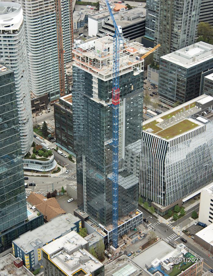
Concrete made with ground glass SCM also meets the necessary performance criteria. It demonstrates suitable strength gain and achieves an elastic modulus equivalent to Portland Cement concrete. It exhibits unaltered creep and shrinkage properties and offers reduced chloride penetration. In 2020, glass pozzolan received an official nod from ASTM International by means of ASTM C1866/C1866M-20, a standard specification for ground-glass pozzolan for use in concrete. And while there are questions about whether ground glass pozzolan can be scaled up to meet industry demand, it nevertheless represents an interesting option for a concrete industry challenged with achieving major carbon reduction.
Concrete mixes featuring synthetic aggregates produced with captured carbon dioxide and mixes using carbon dioxide injection are also being developed. Several companies are working on using sequestered

carbon emitted by industrial processes to produce coated and synthetic aggregates. Other manufacturers inject carbon dioxide from industrial partners into concrete as it is mixed. The carbon dioxide forms a nanosized mineral, calcium carbonate, which adds strength and enables mix optimization, all while eliminating the carbon dioxide from entering the atmosphere.
Still another interesting sustainability technology is a method being pioneered for curing concrete with carbon dioxide instead of water. It promises to reduce carbon dioxide by sequestering it in concrete and significantly reduce the water quantities required for batching.
Perhaps the sustainability strategy most directly under the control of structural engineers is to create materially efficient designs. Designs that are unnecessarily cumbersome, heavy, or poorly conceived pay the price in higher embodied carbon, regardless of the materials used. Conversely, projects that use structural materials in efficient ways that allow the productivity potential of modern construction systems to be fully realized reduce embodied carbon. When combined with the carbon-favorable strategies discussed above, efficiently engineered projects help move the industry toward its net zero carbon goal. The creation of materially efficient, constructible designs is something the American Concrete Institute (ACI) has long focused on. The Institute’s size, however – currently over 35,000 members – and its simultaneous involvement in many different initiatives and activities slows its forward movement. ACI adopted a Center of Excellence concept several years ago to combat this. NEX was rolled out in 2021 to focus on nonmetallic materials. NEU was introduced last year and targets carbon neutrality for the concrete industry. PRO: An ACI Center of Excellence for Advancing Productivity was rolled out in January 2023. All three Centers are separate entities with their own vision and mission, leadership, employees, and bylaws, allowing them to move quickly without encumbrance from ACI. But being
backstopped by ACI and having access to its vast administrative and technical resources provides each Center with the benefit of ACI’s experience and depth.
NEU is active on several fronts, including technology validation and technology transfer. The aim is to review and validate promising new sustainability strategies and help transfer them to wider markets. That process is facilitated by ACI’s global footprint. It provides NEU with the network and resources to help unify the efforts of other agencies and organizations around the world operating in the sustainability arena. Partnerships to facilitate that unification are already being formed.
One of PRO’s early efforts is a 12-part certificate training program on constructability, which ACI recently introduced. The goal is to educate structural designers in construction systems, material efficiency, and buildable design, which will help advance both construction productivity and sustainability. PRO will soon introduce other initiatives, all of which will be focused on these goals.

The carbon reduction strategies discussed here are independent. Each of them can make an impact on its own. But together, and with the many new ideas yet to be conceived, they can dramatically move the sustainability needle. When that happens, carbon neutrality will no longer be a dream. It will be a reality.■


As the name implies, a hybrid roof system combines plywood sheathing and wood sub-purlins supported by open web steel joists and joist girders. Hybrid roof systems offer a more sustainable alternative to metal deck systems. In addition, depending on the market, hybrid roofs can be more cost-effective and faster to build than metal deck roofs. This article investigates hybrid roofs under light to heavy uniform and non-uniform snow loads throughout the Mainland U.S. Sheathing thickness, rafter size, and rafter spacing are adjusted accordingly to provide adequate strength and stiffness. The findings are presented in color-coded maps, enabling owners, architects, and engineers to make instant and accurate decisions.
Hybrid roofs consist of wood sheathing panels supported by wood sub-purlins (Figure 1) spaced at two feet on-center (OC). The sheathing and sub-purlin assembly is supported by open web steel joists (OWSJ), equipped with wood nailers to create an essential interface between wood and steel. OWSJs are then supported by open web joist girders (OWJG), which only have nailers in strategic locations to resist lateral loads.

Hybrid roofs offer a great alternative to metal deck roofs. They are equally durable, produce less carbon footprint, cost less, and can be built faster. In addition, hybrid roofs provide a less expensive roof assembly with a waterproofing membrane above and insulation below, if required. Whereas metal deck has been commonly used when combatting heavy snow, this article highlights the hybrid roof’s ability to support equally significantly high snow loads.
To design a roof system capable of supporting snow loads, the structural engineer must first identify the ground snow conditions using maps from the building code (ASCE 7-16, Minimum Design Loads and Associated Criteria for Buildings and Other Structures, in the U.S.). For the mainland U.S., the ground snow ranges from 0 –100 psf, with ground snow increasing from south to north. In some cases, specific states have a significant variation of snow conditions and require micro mapping by county. The Table summarizes the range of ground snow in these seven states based on ASCE 7-16 tabulated values.
Colorado 25 to 175
Idaho 10 to 190
Montana 11 to 122
New Hampshire50 to 100
New Mexico4 to 30
Oregon 0 to 190
Washington 15 to 190
Table of ground snow range for special states.
Note that extreme snow regions above 6,000-foot elevation and ski areas are excluded and beyond the scope of this article.
This article considers two types of roof snow loads: uniform roof snow load and snow drift. Uniform snow load occurs when snow accumulates upon a flat, wide-open roof, free from obstruction. The relationship between ground snow and uniform roof snow load is provided by Equation 1.
pf =0.7CeCt Ispg (Eqn. 1)
where: pf = flat roof snow load
Ce = exposure factor
Ct = thermal factor
Is = importance factor
pg = ground snow load
Typically, big-box projects are developed in an open area (Ce=1.0) and are equipped with heating systems (Ct=1.0). Therefore, this article assumes 70% of the ground snow is used to establish uniform roof snow load.
Non-uniform snow drift occurs when there is a vertical obstruction the wind can accumulate the snow against, depending on the type of obstruction it encounters. Figure 2 shows common examples of snow drift accumulation, such as roof parapets, rooftop units, high roofs, canopies, etc.
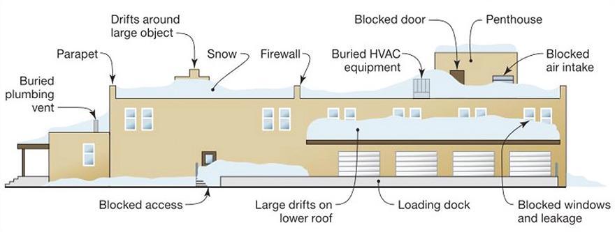
Specifically, this article examines a universally prevalent cause of snow drift: accumulation against parapets. A parapet height of 4 feet 8 inches accounts for fall protection, roof slopes, and roofing/insulation assembly above the wood structural sheathing. Based on this parapet height, the extent of the snow drift zone is calculated to be 12 to 25 feet away from the perimeter of the roof. The band of snow drift becomes narrower around the roof perimeter with the increase in ground snow. Other forms of snow drift are left to the engineer to address per project-specific design requirements.
Hybrid roofs are typically constructed with 5-ply plywood, a wood structural panel (WSP) made from thin layers of wood stacked and rotated 90 degrees against each other. Another common option is the Oriented Strand Board (OSB), a WSP made from multiple strand layers assembled in different orientations packed and compressed together. Although these two types differ in manufacturing, they share the same material characteristics and design function. The WSP selection is generally subject to availability and client-specific request. For this article, OSB is considered. Sheathing thickness varies from a half inch for regions with zero to light snow loads and can be increased to seven-eighths of an inch for heavy snow areas.
The WSP is designed for bending (strength) and deflection (serviceability). Primarily, the panel’s nominal design capacity is computed with uniform loads and is later adjusted to account for external factors such as load duration, moisture, temperature, and panel size.
With the typical panel size being 4 x 8 feet, OWSJs are spaced 8 feet apart, and sub-purlins are spaced at 2 feet OC, as shown in Figure 1. The panel’s longitudinal axis is parallel to the subpurlin; thus, a two-span condition is appropriate when designing the sheathing.
Equation 2 is used to determine the bending capacity:

(Eqn. 2)
where: wb = uniform load based on bending strength (psf)
FbS = design bending strength capacity (lb-in./ft), determined from AWC 2018 Manual for Engineered Wood Construction (AWC-M) Table M9.2-1
l1 = center-to-center support span (in)
A = 96, for two-span conditions
The nominal bending capacity is then multiplied with adjustment factors as provided in Equation 3:
wb.adjusted= wb CD Cm Ct Cs (Eqn. 3)
where: wb = uniform load based on bending strength (psf) CD = load duration factor
CM = wet service factor
Ct = temperature factor
Cs = panel size factor
For snow loading, CD= 1.15. For a conditioned interior, Cm = 1 and Ct = 1. The sheathing panels are placed parallel to the sub-purlin (Cs = 1).
Equation 4 is used to determine the deflection under uniform load: (Eqn. 4)

where: ∆ = deflection (in.)
w = uniform load (psf)
EI = design bending stiffness capacity (lb-in2/ft), acquired using AWC-M Table M9.2-4
l3 = l2 + SW
where: SW = support-width factor = 0.25 inches for two-inch nominal lumber framing, = 0.625 inches for four-inch nominal lumber framing.
l2 = center-to-center support span minus support width (in)
C = 2220 for two-span conditions
Once computed per above, the deflection values must satisfy the roof deflection criteria.
The sub-purlin is designed for bending, shear (strength), and deflection (serviceability), with the nominal capacity modified with applicable adjustment factors. The typical sub-purlin size in light snow regions is 2 x 4 inches and is spaced at 2 feet OC. The rafter size can be increased to 3 x 4, 3 x 6, 4 x 4, or 4 x 6 inches, and the spacing can be reduced to 1 foot OC as needed for buildings in heavy snow areas.
This article examines the capacities of different combinations of sheathings and sub-purlins, provided in Figure 3. The vertical axis indicates each element’s uniform roof snow load capacity, and the horizontal axis shows the load range that the entire assembly can support. The range is based on the lower capacity between the sheathing and sub-purlin. Selecting different sheathing thicknesses and sub-purlin cross sections for each assembly allows for the ability to match the load-carrying capacities for both elements as much as possible.
As discussed before, the mainland U.S. has a vast range of snow loading. In the color-coded map in Figure 4, regions are grouped in ranges of roof snow loads. The colors presented in the map are to be used in tandem with the wood assemblies’ chart in Figure 3.

An example of how to use color-coded maps is: Based on the map in Figure 4, the state of Kansas, represented in purple, has roof snow loads ranging from 10 psf to 17 psf. Referring to Figure 3, the purple color represents an assembly for 0-17 psf roof snow load. Therefore, the roof assembly size for projects in Kansas would be ½-inch sheathing and a 2-inch x 4-inch rafter.
As previously discussed and summarized in the Table, seven states represented with dark yellow have a significant ground and, therefore, roof snow variance. Individual maps are shown for each of these seven states in Figures 5a thru 5g. The areas of the country in dark blue fall under the case study category where the ground snow is not documented and requires a sitespecific study.
In addition to designing for uniform roof snow, special consideration is taken for non-uniform snow (snow drift). As previously mentioned, the snow drift accumulates in a 12- to 25-foot band around the perimeter of the building, accumulating against a 4-foot 8-inch-high parapet. Figure 6 presents the potential framing assemblies for differing snow drift ranges. Note that for snow drift ranging
between 126 to 140 psf, the rafter spacing of 2 feet OC would not work, and the spacing of the rafters would be reduced to 1 foot. As an alternative, roof framing assemblies shown in Figure 7 can also be used in the snow drift zone, and the sub-purlins are to be spaced at 1 foot OC. With the latter arrangement, it would be possible to maintain sheathing thickness and sub-purlin size. The only change would be to double up the sub-purlins in some or all the snow drift zone.
Since wood is an eco-friendly material, the production of wood roofs results in far lower carbon emissions when compared to 1.5 PLB-type metal decks (Figure 8). In addition, wood is a renewable resource as it can be grown indefinitely and can be replaced.
The hybrid roof system utilizes a panelized construction sequence. A bay consisting of joists, rafters, and sheathing is first assembled on the ground (Figure 9). The panelized joist is then lifted and installed onto the roof. The process repeats until the roof’s completion (Figure 10). Having most of the roof’s construction occur on the ground is more efficient. In addition, it decreases the job’s complexity, where construction workers are safe from elevated falls and have better access to assemble each bay.
This article demonstrates the hybrid roof system’s versatility in supporting a wide range of snow loads throughout the mainland U.S. The benefits extend to providing a durable, cost-effective, and sustainable alternative to other structural roof systems.■
Full figures are included in the online version of the article at STRUCTUREmag.org


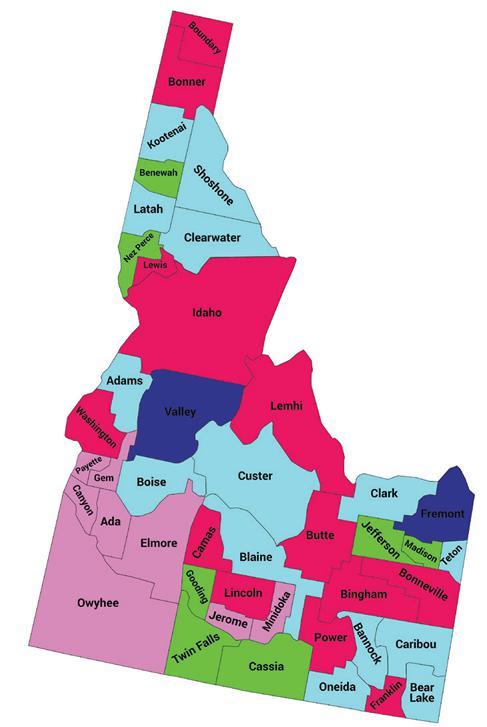


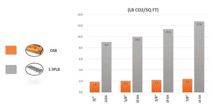
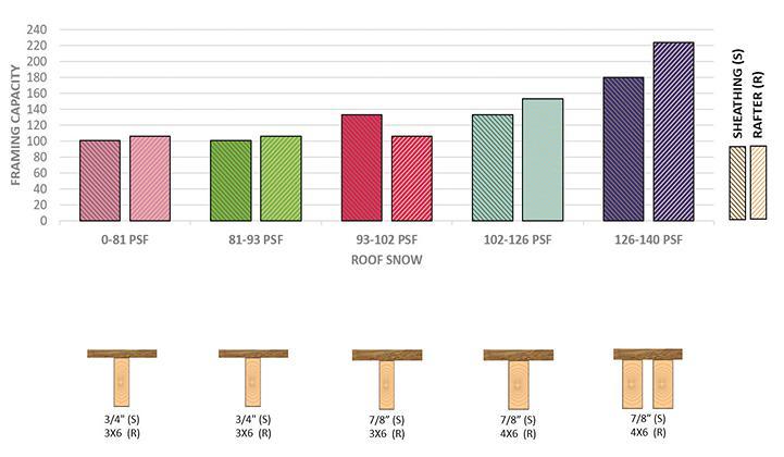
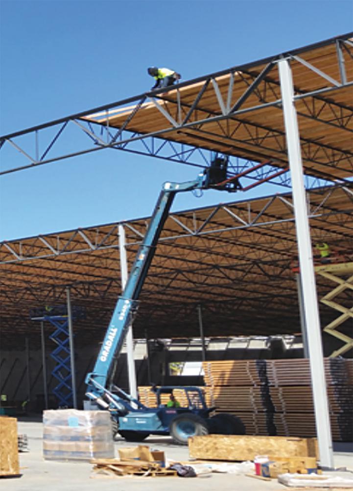
cementprogress.com
PCA’S ROADMAP TO CARBON NEUTRALITY. IT’S POSSIBLE. AND IT’S HAPPENING.
Tallwood 1 at District 56 is a twelve-story mixed-use mass timber building located in Langford, British Columbia, Canada, designed by Design Build Services (DBS), Jack James Architecture, and Aspect Structural Engineers (Figure 1). Tall wood construction is a relatively new typology across North America, and this building is the first structure to be constructed under the British Columbia Building Code’s (BCBC) new Encapsulated Mass Timber Construction (EMTC) provisions, a typology that drastically reduces a building’s structural embodied carbon. EMTC is very similar in limitations and fire requirements to the 2021 IBC Type IV-B construction type. As appropriate to a novel system, the design and construction of this building presented some significant challenges and valuable lessons along the way, with one of the primary challenges being the building’s location: Langford is located in the Cascadia Subduction Zone, a region that is among the highest in seismic demand in all of Canada. Tallwood 1 was the tallest steel-timber hybrid structure in Canada when it was completed in 2021.
Tallwood 1 includes eleven stories of residential rental units over one story of retail commercial units and two levels of underground parking. Below grade construction and a single-story podium are constructed of cast-in-place reinforced concrete, while the upper levels
consist of hybrid mass timber and steel construction. This project was purpose-designed for mass timber from the outset, allowing the early decisions, including grid layouts, lateral load resisting options, and floor-to-floor heights, to be set up appropriately for mass timber. Trying to adapt mass timber to a concrete schematic design is the bigger challenge and can be the reason a mass timber building may not end up being cost competitive.
One of the team’s goals was to enhance the speed of construction of the timber superstructure relative to cast-in-place concrete construction, which is otherwise standard in the region for buildings taller than six stories. To achieve this goal, prefabricated mass timber and steel elements with simple, repeatable, and pre-installed connectors were used as much as possible to eliminate the need for temporary formwork, shoring/reshoring, and concrete strength gain. Floor elements were mostly panelized, while members of the lateral force resisting system were pre-assembled into larger segments prior to delivery to the site.
The typical floor plate at the residential levels consists of pointsupported, two-way spanning Cross Laminated Timber (CLT) panels supplied by Structurlam Mass Timber Corporation (SMTC). Pointsupported CLT involves CLT supported only by columns, eliminating

all or most of the beams from the floor plate and resulting in a flat plate structure that is fast to build and easy to coordinate with architectural, mechanical, and plumbing requirements. The downside of point-supported CLT is that it requires a very tight column grid that is entirely dependent on the available CLT panel sizes. SMTC produces CLT panel dimensions of up to 40 feet (twelve meters) long and 9.84 feet (three meters) wide, driving the column grid layout of 9.84 feet × 11.81 feet (3 meters by 3.6 meters). Knowing the range of mass timber panel sizes available from different suppliers helps inform early decisions like column grid layouts.
CLT panels are built up of layers of dimensional lumber that are laid flat and glued together, with alternating grain directions in each layer. The alternating layer directions allow the panels to span in two directions, giving the panels major and minor strength directions. The major strength direction, the direction parallel to the outer laminations of lumber, coincides with the long direction for the SMTC panels used.
The final structure used the CLT panels as two- and three-span continuous members in the panel’s long direction, with 11.81-foot (3.6-meter) spans in the major strength direction. No bending moment continuity was provided at panel-to-panel joints, so the panels had a single 9.84-foot (3-meter) span in the minor strength direction. Deflection and flexural strength in the minor strength direction ultimately governed the overall panel thickness of 6.89 inches (175 millimeters). The stiffness and strength properties for the panels were calculated in accordance with Canadian Standard Association (CSA) O86:19 Engineering Design in Wood, which introduced CLT design provisions in the 2014 edition.
Floor panels were supported on Douglas Fir glue-laminated timber columns which provided support for ten stories of residential construction. Column sizes ranged from 10.35 inch × 10.47 inch (263mm × 266mm) at the higher levels to 12.36 inch × 11.97 inch (314mm × 304 mm) at the lowest levels, and were kept consistent within each floor.

To avoid passing large compression forces through the floor structure and the associated cumulative perpendicular to grain wood crushing
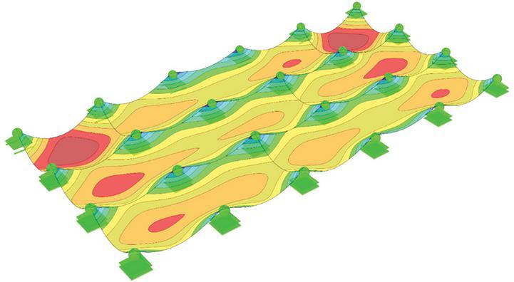
and shrinkage issues that might occur, column-to-column connections pass through the floor panels (Figure 3). Hollow steel structural section (HSS) stubs connected to the tops of columns allow for a reduced cross-section and provide a bearing area for the supported floor panels. Similarly, steel plates attached to the column bases slot into the HSS stubs below (Figure 4). This connector is used throughout the entire project at each column, with variations only for different column sizes. It fulfills many functions since it is largely shop-installed and easy to site-assemble, provides some key integrity to the structure via tension capacity, allows for deformation compatibility as the building drifts laterally under wind or seismic load, and avoids any perpendicular to grain shrinkage or wood crushing.
Analysis showed that over the height of the building, cumulative vertical deformation of the timber elements was relatively minor and

managed at each level with site-installed steel shims at the column-tocolumn connectors with special attention paid to the columns closest to the steel braced frames. With perpendicular to grain bearing completely avoided, deformation was primarily due to elastic shortening of the columns, somewhat amplified by the effect of creep. Cumulative
vertical shortening would be a bigger challenge for a taller building in the 18story (Type IV-A) range.
Punching shear failure, also known as rolling shear for mass timber, was an important design consideration for the CLT floor panels near the column supports. As CSA O86-19 does not include any design provisions for punching shear design of CLT (nor does the 2018 NDS), the panel’s ability to resist punching shear was determined in accordance with a design document by StoraEnso, which is itself based on research by Mestek (references are included in the online version of the article). If the provided bearing area at the column had not been sufficient to avoid rolling shear failure, larger steel column cap plates or reinforcing screws could have been explored to either increase the critical shear perimeter or increase the panel rolling shear capacity, respectively.

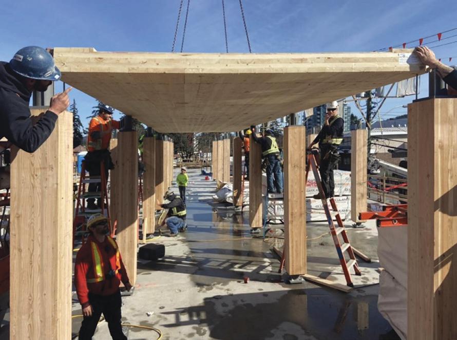
The rooftop penthouse structure deviated significantly from the typical floor plates and included much larger spans, sloped roofs, and vaulted ceilings more suitable to post and beam construction than point-supported CLT. The roof structure incorporated glulam beams and columns to accommodate the larger open floor spaces.
The eleven stories of timber construction are supported on a 23 5/8 inch-thick (600mm) reinforced concrete transfer slab at the second floor. The two levels of underground parking are also of reinforced concrete construction typically seen in the region, with two-way flat plate slabs supported on concrete columns.
To meet the provisions of the EMTC construction type, all loadbearing structural elements were required to achieve a two-hour fire rating, either through encapsulation or a combination of encapsulation and charring. The structural timber members (CLT panels and glulam columns) are encapsulated with two layers of 5/8 inch (16 millimeter) thick Type X gypsum sheathing to provide 1 hour of fire resistance, while the remaining fire resistance was provided through charring of the wood members.
CSA O86-19 Annex B provides design guidance for determining char rates, reduced cross-section dimensions, and calculating member resistances and follows a very similar approach to NDS Technical Report 10. For the fire design of a charred section, the reduced cross-section resistance includes using a material resistance factor (��) of 1.0, the mean strength rather than a specified strength, and a short-term load duration factor, which all increase the structural capacity compared to non-fire calculations. The load demands are specified loads, rather than factored (ultimate) loads. As a result, the fire case, including one hour of char, rarely governed the design of the mass timber elements.
The penthouse roof structure includes exposed mass timber over a large area, which does not comply directly with the EMTC requirements in the BCBC and required an alternative solution application submitted to the Authority Having Jurisdiction (Langford) to approve the code deviation and demonstrate compliance with the objectives and functional statements of the code. The application was approved, and member sizes at the penthouse were permitted to be un-encapsulated and designed for the full two hours of charring.
In very high seismic regions like Langford, mass timber lateral force resisting systems are neither practical nor codecompliant in taller buildings. Most tall timber buildings face a choice of a concrete core or steel-brace framed system. Since there is no one answer for all buildings, it is a worthwhile exercise to review the building size, location, local trades and standard practices, and the building’s unique structural needs. Concrete cores can be advantageous where a single core is adequate for the building and where there is sufficient lead time to pre-build the core, or the core can be slip-formed. However concrete cores tend to have much higher construction tolerances than mass timber or steel, and any misplacement of embeds can slow a project down. Steel is ideal when the floorplate requires a better distribution of lateral elements, to reduce diaphragm drag forces, and because the tolerances are better matched to mass timber tolerances. From a coordination and trades perspective, however, a steel lateral system requires a separate trade to be operating on site during the erection of the mass timber, and unless the steel and timber are modelled together in a single coordinated model, fabrication errors can be introduced.


One of the team’s main project goals was to increase the speed of construction through off-site prefabrication, with a desire that the erection pace of the lateral force resisting system would keep up with the timber installation. Tallwood 1 is also located in a region with very large seismic demands which necessitated the use of a highly ductile lateral force resisting system. With these two constraints in mind, the design team opted to use an Eccentrically Braced Frame (EBF) system that would meet the building’s ductility needs, provide a good distribution of braces throughout the floorplate, and could be prefabricated and rapidly installed onsite.
The EBFs have braces in a chevron configuration, but with the brace-to-beam work points offset from each other to create a short segment in the middle of the beam, referred to as the link, which can yield and remain stable while being subjected to very large inelastic displacement demands. Link members are sized to resist the factored seismic loads, and the remainder of the frame elements (beams, columns, and connections) are sized to resist forces associated with the links reaching their probable upper bound capacity. Link lengths were selected to ensure that the webs yielded in shear rather than in flexure, ensuring that yielding was not concentrated at brace-to-beam connections. Shorter links also result in greater overall frame stiffness prior to yielding. The steel fabricator shop-welded half-frames in multi-story segments (two or three stories at a time, depending on assembly weight and crane capacity) so that on-site assembly consisted of bolted connections limited to columns and link beams. Avoiding structural concrete topping on this project kept the weight (and seismic mass) down, minimized the embodied carbon, and removed the sequencing challenge of a concrete diaphragm when concrete is unlikely to be poured after each level is erected. With only 1.5 inches of (38mm) gypcrete topping, the CLT panels make up the diaphragm.
From a sequencing standpoint, a CLT diaphragm allows the diaphragm at each level to be installed and tied to the braced frames as timber erection proceeds, avoiding additional temporary column bracing or temporary diaphragm ties to ensure temporary stability during construction. The CLT panels are connected together in shear with plywood splines, and steel straps throughout the floorplate provide the chords and collectors, with collectors welded to the steel-braced frames.
The BCBC and the Canadian Wood Code (CSA O86) both include a general requirement for structural integrity via interconnection of the structural members to resist progressive collapse of the structure. Integrity and resistance to progressive collapse are currently “baked” into the steel and concrete designs of tall buildings. Steel connections provide the necessary interconnectivity of elements in steel buildings, and measures like integrity reinforcement reduce the risk of widespread collapse of concrete buildings. Mass timber design of tall timber buildings, being a new typology across North America, does not yet have specific codified measures to ensure integrity is maintained. Looking to the Eurocode, however, provided options to achieve integrity. Tallwood 1 was designed using the “Tying Method” detailed by the Eurocode, which allows horizontal elements to be tied together in the event of a column being removed to prevent further collapse. The column-to-column details include a site-installed bolt connecting the upper and lower connection components together, allowing the columns to hang in tension if a column is damaged or destroyed. The steel diaphragm straps also provide further ties between the CLT panels, though these are intermittent.
As in any project, an ounce of planning goes a long way but does not prevent unexpected and unwelcome surprises. The timber production and assembly were, as hoped, efficient and allowed for rapid assembly on site. The column-to-column connectors in particular allowed for quick erection of the timber elements and minimized crane time, the prefabricated braced frame segments were generally rapid to install and provided both temporary and permanent bracing to the timber as it went up, and the lack of structural concrete topping meant that a third structural material was not a critical path for the project sequencing.
One project challenge however was that the steel supplier and timber supplier each developed their own independent models and produced separate
shop drawings; due to differences in timing between the two as well as the use of different software, the two models were not properly integrated, resulting in some relatively small tolerance issues that nevertheless required site welding and slowed construction somewhat. Ideally, the timber supplier “owns” the steel model and coordination to avoid this kind of slowdown.
Another challenge that was less foreseeable was the pandemic-related supply chain issue, familiar to so many working on projects constructed in 2020 and 2021. The original building design included exterior prefabricated wall panels that were to be installed by crane and allow the building to be enclosed as construction progressed. Wall panels are a critical path item because the BCBC requires that during construction of EMTC buildings, only four stories can be unencapsulated. To progress the timber structure higher, the stories four levels down must be encapsulated with gypsum wall board, and in order to protect the gypsum from moisture, exterior cladding is needed. Unable to receive the wall panels, DBS elected to site-build exterior wall panels, necessitating scaffolding to install them, and adding cost to the project as well as elongating the timeline.
Overall, Tallwood 1 was successfully completed and occupied in 2022, and it serves as an example for future tall mass timber projects in British Columbia and elsewhere. As tall wood structures become more common place, Canadian (and US) codes will further be refined to include specific guidance on topics such as cumulative vertical deformations, drift compatibility, and structural integrity. Until then, the design community can look to European code approaches, project precedents like this one and others, and good structural engineering practices and mass timber mechanics to ensure that tall wood buildings perform as well as any other building. Looking to past projects will also help future tall wood buildings avoid the coordination and workflow challenges to take full advantage of the speed of construction available with mass timber. With appropriate design and detailing, even in highly seismic regions, mass timber is an excellent choice for taller buildings.■
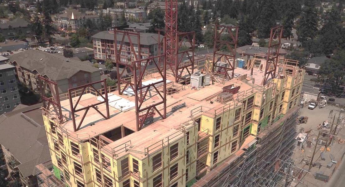
Full references are included in the online version of the article at STRUCTUREmag.org
Jackson Pelling, P.Eng, Jackson is a structural engineer in Vancouver, BC, Canada. His work is primarily focussed on buildings in Canada and the United States, and he provides specialty expertise in seismic design and analysis (jackson@aspectengineers.com).
Ilana Danzig, PE, SE, P.Eng, Struct. Eng., M.Eng, Ilana is a structural engineer in Vancouver, BC, Canada, licensed in British Columbia as well as many US states. With experience in all materials, her focus is mass timber design and detailing, and she works on mass timber projects throughout North America either as engineer of record or design assist engineer (ilana@aspectengineers.com).


Portland International Airport, commonly known as PDX, has been consistently voted among America’s Best Airports by Travel and Leisure Magazine’s reader poll for nearly 20 years, earning the top spot nearly every year. More than that, it is beloved by the people of Oregon and SW Washington as a home base, evidenced by the adoption of the PDX airport code as a moniker for the city itself and by the popular tradition of sharing pictures of your shoes on the iconic carpet to announce you’ve touched down and are officially home from your latest adventure. However, a master planning effort led by the Port of Portland (project owner) in 2014 identified numerous needs to meet increasing passenger demand, which was forecast to double over the coming decades. Initial studies focused on squeezing additional security, ticketing, and baggage processing capacity into the existing terminal were found to be inadequate as a long-term solution, and building a second, separate terminal was undesirable due to the worsened passenger experience of multi-terminal airports, high cost, and duplication of systems and services required. Thus, as the centerpiece of their PDX Next suite of projects, the Port of Portland elected to expand and modernize the existing terminal via the roughly $2 Billion Terminal Core Redevelopment project (TCORE), which as of this writing, is past mid-way through six years of planned construction. Maintaining entire terminal operations while expanding and massively overhauling the facility created a monumental challenge, requiring a skilled and fully engaged project team with creative problem-solving and plenty of grit. Fortunately, the Port, a design team led by ZGF Architects, including KPFF as Structural Engineer and Hoffman-Skanska Joint Venture (HSJV) as CMGC, has demonstrated great teamwork over the past 7+ years to deliver major milestones one after another successfully. Confidence is high that construction
will successfully complete over the next few years (Phase 1 opening is anticipated in 2024, with completion in 2025), resulting in a revolutionized terminal experience featuring outstanding functionality and breathtaking design.
The existing ~300'x1000' terminal at PDX was constructed, expanded, and modified over six decades and comprised 11 major separate structures, all of which are being significantly altered and partially or fully demolished by the TCORE project. The project is separated into two major phases. During Phase 1, the existing ticket hall and two security processing nodes are maintained. In contrast, other portions of the existing terminal are isolated, modified, and/ or demolished. A major expansion is added to the west (known as the Western Expansion, or WE), partially consuming portions of Concourses C and D. These modified/expanded areas are being built out during Phase 1 to house a new ticket lobby, security processing, baggage handling, and other core terminal functions. Once Phase 1 is complete, Phase 2 entails selectively isolating and modifying/ demolishing the existing ticket lobby and security node areas, resulting in a comprehensive, cohesive modern “big room” terminal at the end of the project.
Future flexibility and adaptability are among the project core values identified by the Port since the project intends to serve the growing Portland region's needs for decades without a need for further significant terminal expansion. This goal is accomplished by demolishing the existing terminal structures above the main “enplaning” passenger floor level, creating a wide-open terminal space covered by a new long-span roof, with space below for smaller independent interior structures for concessions, offices, restrooms, and services that can be removed and/or modified over time as changes occur in ticketing,
baggage handling, and security processing. Obstacles to flexibility were minimized by supporting the new approximately 400' wide x 1000' long roof structure with only 34 steel Y-Columns, generally spaced at 100'x150' grid spacings, which serve as both gravity and lateral support for the roof as cantilever columns with seismic isolation bearings at their top connections to the roof.
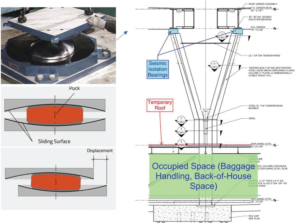

The decision to seismically isolate the roof was made to avoid additional lateral elements that would limit future flexibility, to reduce foundation requirements, to achieve Port seismic resilience criteria, and to facilitate a phased modular construction sequence over the occupied facility, for which the City of Portland required code compliance, including seismic considerations, at all times during building occupancy.

Maurer supplied the double-friction pendulum isolators, which allow up to 22.5" of relative lateral movement between the top of the column and the roof. Each supports up to 450 kips of roof weight.
Seismic Resilience is a driving force in the TCORE project, motivated by the current understanding of significant seismic risks posed by the potential for a major event along the Cascadia Subduction Zone (CSZ), which threatens the west coast region from British Columbia through Washington, Oregon, and into Northern California. The State
of Oregon has developed the Oregon Resilience Plan to prepare for the potential of such a major event. PDX has been identified as a critical facility for the region, both for emergency response immediately after an event and for economic recovery in the months following. The Port, in turn, developed voluntary seismic resilience criteria to ensure PDX will be able to fulfill this need, targeting a Magnitude 9 event on the CSZ, roughly equivalent to a 2475-year MCE event on the CSZ, with the new structures for TCORE designed for structural immediate occupancy performance, and nonstructural elements designed to be repairable in a short timeframe. The site’s uppermost 100' of soil has also been identified as liquefiable, potentially settling 16" under MCE/CSZ shaking. To achieve resilience goals, the on-grade level of the Western Expansion is designed to function as a pile-supported suspended reinforced concrete floor if the soil below settles. With code-required peer review, PerformanceBased Seismic Design (PBSD) was utilized for the new TCORE structures using a PERFORM 3D model capturing the new roof, Y-column supports, and full Western Expansion structure for nonlinear response history analysis. 11
code-required MCE ground motions were run for four separate cases of max/min bounding of foundation and isolator properties, along with other CSZ voluntary resilience ground motions. Of the (34) Y-columns supporting the roof, (16) occur within the Western Expansion (WE), where they are tied into the enplaning level steel floor framing and grade-level concrete slab and beam structure with pile caps. The Y-columns outside of the WE mainly occur
within the existing terminal, cantilevering up from independent pile caps, supported by battered micro-piles to provide vertical and lateral stability without grade beams, passing through an enlarged opening in the existing enplaning floor structure, with seismic joint covers around their perimeter to allow relative seismic movements and settlements between the new columns and surrounding floor structure.
As part of the Port’s voluntary seismic resilience goals, all existing terminal structures were evaluated for expected performance under the selected CSZ event and modified to improve safety. While the potentially large liquefaction settlements of many of the existing pile foundations, which do not extend far enough into dense sands below to prevent movement, do not allow for resilience in the existing terminal on day one, and a complete foundation retrofit is not feasible within the existing terminal due to the extensive impact on operations and systems, the TCORE project gives the Port the ability to upgrade existing structures one at a time in the future as areas are made accessible by future modifications to the baggage handling system, for example.
Achieving the function and flexibility of a big-room terminal while maintaining the beloved intimacy and character of PDX required an inspired design. The new roof vividly conveys the design intent of an inspiring and comfortable walk through a forest, with distinct spaces defined by the vaults, domes, and plentiful and varying
daylight provided by (49) large skylights, numerous clerestories, and tall perimeter curtain walls. The roof forms and interior structures combine to establish the feel of passing through a series of rooms on a scale that is more comfortable to travelers than traversing a single massive space. Combined with the plentiful biophilic design elements of exposed wood and extensive landscaping featuring live interior trees, the transformed PDX terminal is poised to become both a pleasant, low-stress travel experience and an exciting destination.
The visual centerpiece of the TCORE design is the new mass timber hybrid roof, which will cause even the most jaded travelers to pause, look up, and experience a “wow” moment when first witnessed. The roof is composed of 20' wide steel framed girder sections spaced at 100' with 6' deep steel plate girders on each side spanning up to 150', perpendicular 80' long glulam infill beams spaced at 10' on center between, and with glulams cantilevering to the roof edge in some areas. The glulam beams are 6 ¾" wide, with (11) main beam geometries varying in depth and geometry from flat to arched and tapered, used to form vaults and domes across the roof area to define the space architecturally between flat girder sections, with clear height varying from approximately 36' to 48' above the main floor below, providing ample space for open areas, mezzanines, and interior shell structures, as needed. Around the perimeter of the roof, the glulam beams are held inboard by 6' to 10', with the roof edges supported by smaller steel beams located above the roof deck cantilevering out from the glulam beams below and integrated into the roof edge parapet, allowing for maximized clear glazing heights range from 43' to 52', providing ample daylight when combined with the myriad skylights and clerestories, minimizing the need for electric light and providing dramatic views of the active airfield and surrounding picturesque setting.

Below the glulam beams is a field of 3x6 dimension lumber spaced at 12" on center spanning between glulams, which serves multiple purposes, as it manages daylight, improves acoustic performance, braces the bottom of the glulam beams, and defines the aesthetic of the roof, all for a fraction of the cost of a conventional ceiling system. ZGF has worked wonders with these simple boards to create a plethora of expressive forms that define the space and excite the eye of the viewer while coordinating a design that is both practical and multi-functional.
The large movements of the seismically isolated roof posed a considerable challenge when detailing the long-span curtain wall system, mainly hung from the new roof. The curtain wall vertically simple spans from the roof to the mezzanine/wind girt level between 30' and 40' for wind loads, pivots for out-of-plane seismic movements, and moves rigidly in-plane with the roof as a vertical glass and structural silicone

diaphragm. Seismic joints with popopen covers occur at curtainwall ends, corners, and transitions to allow relative lateral seismic movements. The unique curtain wall design by MiTek and KPFF features 10' wide x 12' tall, insulated glass units without mullions at the floor level, with structural silicone in the vertical joints, providing unparalleled lighting and view opportunities at the enplaning level. At the long-span glazing above the mezzanine joint, exterior extruded aluminum mullions are held off the outside face of the glass by approximately 6" with periodic standoff connections, providing for a continuous interior glass surface with exterior fins that assist with sun shading while creating a distinct and appealing aesthetic.
In addition to the main seismically isolated roof structure, a pair of unique 60' wide structures span 150' over the new security checkpoints and cantilever 45' over the existing terminal floor below, supporting a public mezzanine level and mechanical penthouse level above, with a roof extending through a large opening in the main roof, surrounded by seismic joint covers. Each mechanical mezzanine structure is supported by (4) 36" square built-up steel box columns, with wall plates up to 4 ¼" thick constructed of Grade 70 steel. The long spans and cantilevers are supported by articulated story-depth steel trusses on each side. These trusses provide gravity support and lateral resistance, acting effectively as a truss-moment frame system in the longitudinal direction with a buckling restrained braced frame diagonal acting as
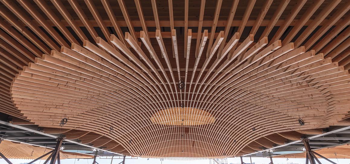
a fuse to limit overall seismic forces in the system. In the transverse direction, lateral resistance is provided by steel moment frames with reduced beam section beam end connections framing into the box columns. This unique lateral system was reviewed as part of the Performance-Based Seismic Design Peer Review, as the truss frame falls outside of prescriptive code seismic force-resisting system definitions.
As one of the largest building construction projects in the region’s history, intending to serve a future passenger load of over 34 million taking off per year, TCORE represents a generational opportunity to benefit the Portland area. From the evaluation of the multitude of existing structures to the design of the new landmark roof, over the past 7+ years, KPFF’s team of nearly 100 structural engineers contributing to the project have played a key part in bringing to fruition a project that the Port of Portland, project team, and the entire community can take great pride in for generations to come. As engineers, we have been blessed to have the opportunity to use every tool at our disposal, from complex modeling to physical load testing, to work through a plethora of unprecedented challenges and opportunities. Once Phase 1 is complete, we invite you to visit PDX and experience the reinvented terminal for yourself. Don’t feel self-conscious if your eyes bulge and your jaw drops as you whisper “wow” – the same thing happens to us every time we look up.
Look for Part Two in an upcoming STRUCTURE issue for more information on the novel and experimental design approaches that made this project a reality.■
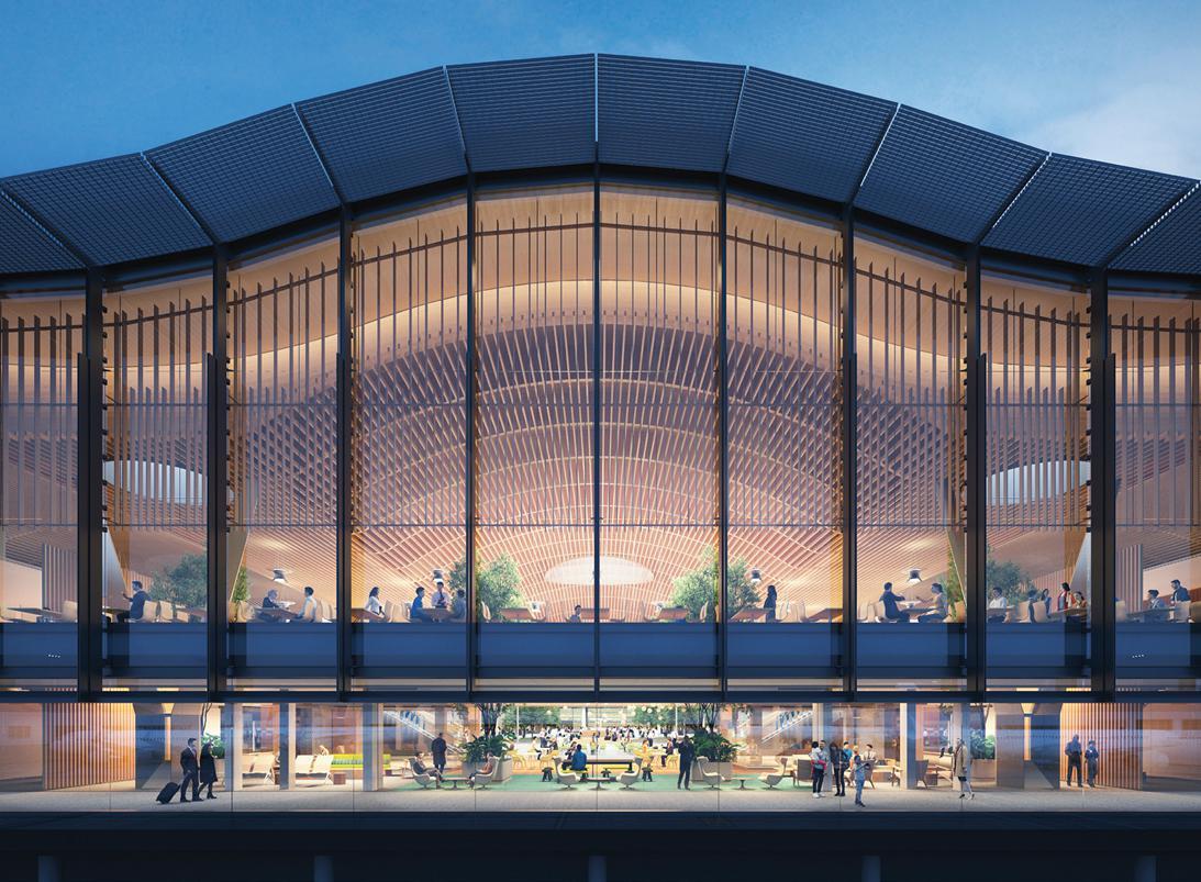
In January 2022, WTW A&E released a survey of senior claim managers from twelve leading professional liability insurance carriers for architects and engineers in North America. The survey focused on emerging risks and claim trends in the design profession. This article is the first of a three-part series that will address the survey’s key findings and offer some insights and recommendations on what design firms can do to mitigate their risk of costly claims and client disputes. In this issue we will discuss social inflation and cyber liability. Future issues will discuss the impacts of climate change, Covid-19, contracts, the enhanced risks associated with certain project types and staffing concerns.

Underwriters use two metrics to evaluate a firm’s loss history. The first is frequency. How often do firms have claims? The second is severity. When
those claims happen, how expensive are they? Almost half the carriers we surveyed said that they are seeing an increase in frequency of claims being made, and nearly three-quarters said that they are seeing an increase in the severity of those claims.
Severity is the more important of the two issues because the rating tools used by underwriters heavily factor in the loss ratio calculation, which compares the premium paid to the claim’s dollars incurred. The average claim usually costs around $75,000. A severity claim is typically classified as a claim that costs $250,000 or more. Severity hits the loss ratio and drives increased pricing.
One of the carriers that responded to the WTW A&E survey offered this comment concerning severity claims: “We’ve seen a steady and fairly extreme uptick in severity, primarily in our large firm’s segment arising from bodily injury-related losses.” (They define large firms as those generating over thirty million dollars in revenue annually.)
“The single driving cause we have isolated is social inflation. And now we have supply chain interruptions, a looming recession, and economic inflation to contend with as well. For context, claims that five years ago may have been presented to us for $250,000 are now demanding a million or more for the loss. For example, $1 million claims in 2014 are now coming out of the starting blocks at around $3 million or more.”
In addition, claims are taking longer to settle. The consensus from our panel is that claims take two to three years to resolve on average, and outliers can take ten to fifteen years to resolve. This highlights the importance of good documentation practices so that you can be well-positioned to tell your story if required in the distant future.
The first of our mega-trends is social inflation. That means that juries are giving out ever-increasing awards in their verdicts. One of the driving factors behind this trend goes back to a book that was published in 2009 by a plaintiff’s attorney on “reptile theory.” This theory espouses that the plaintiff’s counsel can maximize the verdict by tapping into the primitive self-preservation instincts of a juror by painting the defendant as dangerous to the juror and their community. Reptile theory espouses that you can get a bigger award if you can convince the jury that the case is not just about providing justice for the defendant but also safeguarding their family and community. This tactic has been used fairly successfully, and we see the result in verdict awards that are increasing much faster than the rate of inflation.
Another trend driving increasing litigation expense is litigation financing, where a third party, unrelated to the lawsuit, provides capital to the plaintiff involved in litigation in return for a portion of any financial recovery from the lawsuit.

We have seen a rash of bodily injury claims involving engineering firms and construction and traffic accidents in work zones. Right or wrong, the engineer is often dragged into these lawsuits. The engineer is typically not negligent in most of the cases that we’ve seen. However, you often have a very sympathetic plaintiff, and the state usually has sovereign immunity.
Another carrier that responded to the WTW A&E survey commented: “We have identified firm profiles and services that we feel are most exposed to severity claims. Most are large civil firms with construction management or site observation services working on large infrastructure projects, many of which are design-build delivery and no longer covered under project-specific policies. This isn’t the extent of where we are seeing severity claims, but these are the risks where we are finding we can’t really get our arms around the exposure even with firms who are well risk-managed and have good loss histories.”
The defensive strategy is to hit the job site safety exposure head-on and hard. The first step is to insert a requirement in the design professional’s contract that the contractor is solely responsible for job site safety. This should be non-controversial. The second step is to request Additional Insured status for design professionals on the contractor’s Commercial General Liability policy. The contractor traditionally manages the job site safety exposure, and part of managing that exposure includes ensuring that exposure. The third step in managing the job site safety exposure is to live within the contract terms and not assume responsibility for means and methods by virtue of our conduct on the job site. The classic example would be telling the contractor how to do his job. It can sneak up on you.
Sometimes a contractor will run into a problem and ask the design professional to show him how to fix it. It could be getting involved in the design of temporary structures or advising on job site safety. For that to happen, our contract must say that we are not responsible for job site safety, and our conduct must conform to the contract. We want to train our staff regarding our construction administration responsibilities and avoid documenting safety concerns because, if an engineer is sued for a job site injury, the only way to get out of that case without paying money is to file a successful Motion for Summary Judgement. And the standard for summary judgment is high – there must be no material question of fact.
We want to back this up with a request to be named as an additional insured on the contractor’s general liability policy. We need to require that in our agreement with the owner so that the owner will make it a term in the general conditions of the construction contract. The best time to ask for Additional Insured status is when the contractor is bidding on the job and is incentivized to cooperate. Thousands of
insurance companies provide general liability coverage, and the top-tier carriers can provide Additional Insured status. If a contractor cannot provide Additional Insured status, they likely chose the lowest cost provider as their insurance partner. We would consider this a negative factor when evaluating that contractor’s capabilities. There are two very important things to include with the contract in order to comply with the requirements of modern Additional Insured endorsements. The first is that the additional insured status provided will be on a primary and non-contributory basis. This means that the contractor’s insurance comes first and does not seek contributions from the design professional’s insurance. The second thing is that we need to specify what limits are available to the additional insured. I would recommend the full limits available to the contractor. But suppose we don’t say how much insurance is available to the additional insured. In that case, the carrier can take the position that there is no coverage for the additional insured because you did not specify how much was required.
The owner is getting named as an additional insured on that contractor’s GL policy. And that’s because that’s where the insurance belongs - with that party that can manage that risk. Even though we hear that contractors frequently push back against adding design professionals to their policies, we find that some of our professional design clients are actually quite successful in getting added as additionally insured to the GC’s policy. This is often at little or no additional cost to that contractor.
The cyber liability insurance market has become a challenging market due to the increasing frequency and severity of cyber-related claims. Ransomware has become the number one threat, as virtually any business can be targeted, not just those with troves of personally identifiable information. This has resulted in a great deal of underwriting scrutiny around cyber. An applicant firm needs to have very specific controls in place, including multi-factor authentication (MFA) and staff education plans to combat social engineering for underwriters even to consider offering you insurance. A cyber liability application will give you a list of defensive measures to consider. It’s also very important for firms to have an incident response plan in place to know what to do in the event of a cyber-attack. These attacks often come at a very inopportune time, such as over a weekend or a holiday. The best practice is to identify all the stakeholders within your business that will need to respond and take specific action in the event of a cyber-attack so that they can be quickly notified.■
Dan Buelow is Managing Director of Willis A&E. He leads a team of insurance and risk management experts that are exclusively dedicated to providing insurance and risk management solutions to Architects and Engineers. Dan can be reached at (Dan.Buelow@wtwco.com) or 312-288-7189.
Mark Blankenship is the Director of Risk Management for Willis A&E. He draws on his 25 years of experience in professional liability claims, underwriting and brokerage to provide risk management guidance, claims advocacy and contract review support. Mark can be reached at (Mark. Blankenship@wtwco.com) or 312-525-2281.
 By Frank Griggs, Jr., Dist. M.ASCE, D.Eng,. P.E., P.L.S.
The Dubuque and Pacific Railroad began construction on a 29-mile line extending from Dubuque to Dyersville, Iowa in 1857 followed by another 49-mile section to Jessup by 1860. It was purchased by the Dubuque and Sioux City Railroad which extended the line to Cedar Falls, Iowa. The Illinois Central was formed on February 10, 1851 as one of the first land grant railroads and was to run northerly from Cairo at the southwestern tip of Illinois northerly to Chicago and then westerly to Freeport and on to Dunleith, Illinois for a distance of 453 miles. It arrived in Dunleith in 1866. It leased the Dubuque and Sioux City Railroad line in 1867 to extend its line into Iowa.
Congress on July 25, 1866 authorized the bridge as one of eight bridges on the Mississippi and one on the Ohio River. Its requirements were the same as the Quincy Bridge (Structure May 2023) It could either be a low-level bridge with a swing or a high-level bridge. If it was a low level bridge it was to have a “pivot draw-bridge, with a draw over the main channel of the river, at an accessible and navigable point, and with spans of not less than one hundred and sixty feet in length in the clear on each side of the central or pivot pier of the draw, and the next adjoining spans to the draw shall not be less than two hundred and fifty feet; and said spans shall not be less than thirty feet above low-water mark, and not less than ten above
extreme high-water mark.” If a high-level bridge it “shall not be of less elevation, in any case, than fifty feet above extreme high-water mark as understood at the point of location, to the bottom chord of the bridge; nor shall the spans of said bridge be less than two hundred and fifty feet in length, and the piers of said bridge shall be parallel with the current of the river; and the main span shall be over the main channel of the river, and not less than three hundred feet in length.”
Section 9 of the Act stated,
And be it further enacted, That a bridge may be constructed and maintained across the Mississippi River, between Dunleith in the state of I llinois, and Dubuque, in the State of Iowa, with the consent of said States previously given or hereafter acquired, with the same privileges, upon the same terms, and under the same restrictions as are contained in this act for the construction of a bridge at Quincy, Illinois
Illinois approved the bridge on February 14, 1867 and Iowa approved a corporation known as the Dunleith and Dubuque Bridge Company for the purposes of constructing a railroad bridge across the Mississippi river from the city of Dubuque, Iowa, to the city then known as Dunleith, in the state of Illinois
on June 3, 1867. In addition to the bridge it required a 980' long tunnel at Dunleith.
In December 1867 R. B. Nason, the Chief Engineer, sent a Notice to Contractors stating,
The superstructure will be entirely of iron, the draw of all wrought iron, and the remainder of the bridge of all wrought iron except the top chord, which may be of cast iron. Proposals will be received on Post’s, Pratt’s, Bollman’s, Linville and Piper, or any other approved plan of superstructure, with some slight modifications. No single bid will be received for the whole work. But they must be separate for the superstructure, for masonry, foundations, and protection to draw pier and for the work connecting West end of bridge with the Dubuque and Sioux City Railroad.
It is of interest that on their stock certificate they had an image of the Rock Island Bollman Swing span, thinking at the time that their swing span would be similar.
The Iron Railroad Bridge across the Mississippi River at Dubuque, Iowa, has been let to the Keystone Bridge Company of Pittsburgh, Penn. All of the prominent bridge builders submitted plans and estimates and the competition was quite spirited, several of the bids being within a trifle of each other; but after careful consideration, the “Linville & Piper” patent truss [really a Whipple double intersection] which has given such perfect satisfaction upon the Pennsylvania, Steubenville, and other leading lines where it has been used, was adopted. The entire bridge is to consist of a draw or “pivot” span of 360 feet, 2 spans adjacent thereto of 250 feet each, and 4 spans of 225 feet--in all 1,760 feet. The contracting parties at first decided to select the plan submitted by the Keystone Bridge Company, in which the top chord was composed of cast iron, but subsequent investigation of the superior merits of their entire wrought iron truss bridge, embracing their patent swelled wrought iron posts, upset weldless chord links, and all of their more recent improvements, induced them to incur the additional expense and contract for the latter.
Andrew Carnegie was the Keystone representative that urged the adoption of an all wrought iron bridge arguing, “In the case of the wrought-iron chord, the bridge would probably only bend; in the case of the cast-iron, it would certainly break and down would come the bridge.” All of the posts were Keystone
sections and the top chord of latticed wrought iron channels. Jacob Hayes Linville of the Keystone Bridge Company designed and built the bridge on a modification of the Whipple double intersection truss. There were eight bids and Keystone’s, while not the lowest, was awarded the contract on January 13, 1868 for $275,000. The foundations were let to Reynolds, Saulpaugh & Co. for $242,000. The same firm won the contract for 2,400' trestle on the Iowa side for $52,000.
Starting on the Iowa end the bridge had four spans of 225', one span of 250', a swing span of 360' (with two clear openings of 160'), and one span of 250'. All of the top chords were straight except the swing span which was curved. The iron portion of the bridge was approached by a 2,400' wooden trestle on the west end and on the Dunleith side by an 835' long tunnel. The bridge overall would have a length of 1,760'.
The bridge, the first of all wrought iron, across the Mississippi was tested on December 22 but due to cold and wind the results were questionable and the test repeated on December 30, 1868 with only a 1 5/8-inch deflection under a weight of five locomotives weighing 245 tons. The bridge was officially opened on December 22, 1868, one month ahead of schedule, for freight and passenger traffic. It was replaced in 1900.■

The built environment is a powerful tool for improving people’s lives, sense of wellbeing, and overall health. As such, good design is an important tool in the fight for equity across populations. Unfortunately, design services are often a luxury, inaccessible to those who might benefit most from them. However, architects and engineers are not able to operate without resources. To explore these topics, ARCHIVE Global and Silman’s Building Equity Initiative teamed up to host a conversation amongst New York City practitioners to evaluate barriers and best practices when addressing pro-bono and low-bono design work. Below is a documentation of the shared challenges, strategies, and opportunities voiced by architects and engineers in attendance, focusing particularly on the structural engineering perspective.
Opportunities voiced in the discussions included the creation of cross-collaborative partnerships, emphasis on the value of relationship building, and looking beyond the traditional design community for allies.
Design firms expressed that common challenges centered around lack of funding/resources, limited time, gaps in collaboration, and misaligned expectations between the firm and client regarding pro-bono and low-bono work. Moreover, key strategies mentioned for overcoming challenges within this sector of work include capitalizing on personal passions and creating clear scopes of work to define client expectations. Likewise, opportunities voiced in the discussions included the creation of cross-collaborative partnerships, emphasis on the value of relationship building, and looking beyond the traditional design community for allies.
The first shared challenge was that limited funding for pro-bono and low-bono work prevented firms from doing this work substantially and sustainably. In particular, this was a challenge faced by smaller firms, as resources can be limited. Thus, often, even given the best intentions, paid project work tended to take precedence over probono and low-bono work and limited the amount of this work firms were able to take on. In addition, from a staffing standpoint, this type of work often depends on the passion of staff members. This lack of resources can quickly lead to burnout as staff gets too busy. And their enthusiasm may dissipate as they are tapped for more paid work to compensate for the financial inability to engage full-time staff with pro-bono and low-bono work alone.
A second common challenge voiced was the misalignment between client expectations on pro-bono and low-bono projects versus designer limitations regarding time and resources. Many firms have
faced the challenge of having clients buy into the firms’ time while also understanding their limitations of scope and expertise. As a result, misaligned expectations between firms and clients lead to outcomes that do not fit the goals and constraints of both sides. Thus, there is a need to manage and align expectations from the start of a project. For structural engineering firms, in particular, connecting with clients and potential projects is a major challenge. Outreach and communication with architects and nonprofits to find pro-bono and low-bono projects can be time-consuming and unpredictable. Often these efforts are fueled by the passion of younger staff members who have less experience with client outreach and thus may be intimidated or not well equipped to make the connections necessary to maintain a steady level of pro-bono and low-bono work, or once a project gets started, to navigate client relationships.
One strategy some firms have taken to address these challenges is to create a framework that treats pro-bono and low-bono work similarly to paid projects by tracking time spent and paying employees for that time. This approach can hold firms and clients more accountable, indicating that a firm has a top-down commitment to this work. Alternatively, other firms include pro-bono and low-bono work within their business development sector, tracking hours donated and setting goals to hold the firm accountable to prioritize that work. To better align client and firm expectations, firms often break down a project into an initial scope of work or feasibility study as a starting point. This ensures that the client and firm are aligned with their goals, needs, and limitations before proceeding with a full-scale project.
One of the main opportunities that came out of the discussion included forming cross-collaborative partnerships with other design firms, community based organizations, and nonprofits, emphasizing the value of in-between connection building. Although very valuable and central to design work, relationship building often operates in a silo compared to the design and construction processes. More crosscollaboration among different disciplines can help reduce the time required to make these connections and reduce the resource depletion and burnout that often results.
Firms are also continuing to navigate how to strike a balance between conducting high-quality work while also having the ability to show off their work. 0One innovative opportunity discussed was to create a funding model where paid projects’ funding could be funneled into pro-bono and low-bono work to help combat limited resources and the inability to engage full-time staff. Likewise, tapping into the younger generation of architects and designers who are interested in using their skill sets for good could be useful for getting the momentum going. However, this approach does not eliminate the need for support for these initiatives by firm leadership.
As a result of the productive workshop and discussion among design firms, a critical goal is to maintain momentum toward continuing and expanding the conversation beyond workshop participants. For example, creating an email listserv for the future exchange of ideas

more fluidly could facilitate seamless collaboration across sectors, clients, and disciplines. Moreover, to better align expectations between firms and clients, there were suggestions to create guidelines to educate each party - for example, the client/nonprofit, on the process of pro-bono and low-bono design work for AEC firms. Overall, there was a strong emphasis among firms in attendance to further explore coalition building to continue supporting each other and share challenges, successes, and strategies for pro-bono and low-bono projects.■
Maya Stuhlbarg is a Senior Project Engineer at Silman and Co-founder of BEI. Silman, a structural engineering firm, started its Building Equity Initiative (BEI) in 2020. It provides pro-bono/ low-bono professional engineering services to create spaces that strengthen communities and contribute to societal equity (maya.stuhlbarg@silman.com).
Sarah Ruel-Bergeron is the Executive Director of ARCHIVE Global; she is a licensed architect and holds a certificate in Global Health Practice. ARCHIVE Global is an NYC-based nonprofit that works with resource-limited communities worldwide to improve health with housing design interventions through partnering with local groups on costeffective, scalable housing improvements (srbergeron@isuh.org).
Jessica Schneider is a recent graduate of Columbia University’s dual degree MSW/MPH program and research assistant at ARCHIVE Global (js@archiveglobal.org).
Justin Den Herderis a Principal and Studio Leader at Silman (justin.denherder@silman.com).
The committee aims to promote the application of structural fire engineering in practice.
By Erica Fischer, Ph.D., P.E. and Negar Elhami-Khorasani, Ph.D.This article provides an update on the progress and focus of the American Society of Civil Engineers/Structural Engineering Institute’s (ASCE/SEI) Fire Protection Committee for the next two years. The aim is to support the field of structural fire engineering through collaboration and sharing of knowledge across industry and academia. Over the last few years, the field of performance-based structural fire engineering has expanded with a multitude of published guides, standards, and specifications in the United States (U.S.). The new documents are the result of decades of research. Below is the chronological breakdown of various significant published documents:
• 2016: First time publication of ASCE/SEI 7 - Minimum Design Loads and Associated Criteria for Buildings and Other Structures, Appendix E: Performance-Based Design Procedures for Fire Effects on Structures enabled the use of performance-based fire design
• 2018: Publication of ASCE Manual of Practice 138: Structural Fire Engineering
• 2020: Publication of Advancing Performance-Based Structural Fire Engineering Design in the U.S. through Exemplar Procedural Guidance
• 2022: Expansion of Appendix 4 of the American National Standards Institute/American Institute of Steel Construction’s ANSI/AISC 360 Specification for Structural Steel Buildings provides more guidance and resources to structural engineers
• 2022: Publication of Post-Earthquake Fire Assessment of Buildings: Evaluation Framework through ASCE/SEI
• 2022: Publication of Fire Design Specification for Wood Construction through the American Wood Council
• 2022: Included target reliability levels for performance-based design of structural systems subject to uncontrolled fires in Chapter 1 of the ASCE/SEI 7: Minimum Design Loads and Associated Criteria for Buildings and Other Structures
The listed documents cover different aspects of performance-based structural fire engineering; however, they may not interpret performancebased structural fire engineering in the same way. ASCE/SEI 7 is the governing document and should be fulfilled when performance-based structural fire engineering is implemented.
With the development of the above documents, it is critical to engage with members of industry, academia, and authorities having jurisdiction to educate and prepare a broad audience for
the in-practice implementation of performance-based fire design. To accomplish this, the following initiatives are being developed: Case study history: The committee is collecting examples of projects in the U.S. where performance-based structural fire design has been implemented. These case studies will serve as a repository for the industry to build on. The case studies provided within the Advancing Performance-Based Structural Fire Engineering Design in the U.S. through Exemplar Procedural Guidance did not go through an authority having jurisdiction (AHJ). Although the case studies provided excellent examples of how the structural engineer might approach the design, they did not provide for final, approved designs. In addition, the committee is synthesizing papers and resources in a searchable and user-friendly repository for use by a diverse audience, including building officials, practicing structural engineers, architects, and educators.
Roundtable discussions: The committee plans to hold roundtable discussions to bring together diverse perspectives of projects that have employed performance-based fire design. The aim is to disseminate advances in the field, recognize and address barriers in the application of structural fire engineering, and identify the requirements for successful projects in practice. As a first step, the committee has sponsored a session at the 2023 ASCE/SEI Structures Congress that consists of a roundtable discussion with representatives from professional committees in the U.S. who develop codes, guidelines, documents, and technical content related to structural fire engineering. The panelists presented the latest activities of their committees, future directions, and how the committee products can benefit the industry to design structures for fire.
The proper assessment of risk and implementation of strategies to ensure wildfire resilience require an interdisciplinary approach, involving stakeholders, industry, and community engagement.
A “Fire Load” task group within the Fire Protection Committee was formed in 2021 in response to an identified need to provide guidance on the definition and modeling of design fire loads in buildings to be used in performance-based structural fire design. The task group is preparing a report on objective criteria, best practices, and examples for the determination of design fire loads. As such, the report aims to provide engineers, designers, and stakeholders with a common framework to discuss the rationale and assumptions adopted for the fire loads. The report outline includes sections on performance objectives for design, definition of design-basis fires, selection of fire models, methods to interface the results of fire models with structural models, robust evaluation of fire load, and current developments and challenges. The task group is on track to have the report published in 2023.
The frequency and intensity of destructive wildfires that impact communities have been rising and this trend is expected to continue. The proper assessment of risk and implementation of strategies to ensure wildfire resilience require an interdisciplinary approach, involving stakeholders, industry, and community engagement. Over the past decades, civil engineers have contributed significantly to devising solutions for a range of natural and man-made hazards (e.g., earthquakes, hurricanes, blasts,
and more), but they can play a larger role in addressing the impacts of wildfires inside communities. For example, structural engineers can contribute to developing an understanding of the mechanisms by which structures ignite and establishing design and assessment methods to achieve fire-resilient structures, including critical structures such as hospitals and schools, and resilient communities. The committee has sponsored a session at the 2023 ASCE/SEI Structures Congress to engage wildfire scientists and structural engineers to discuss wildfires and their impacts on structures. The outcome of these discussions will be reviewed to guide prioritization of the committee’s future actions in supporting and advancing the field.
■
Full references are included in the online version of the article at STRUCTUREmag.org

Erica Fischer is an Assistant Professor at the Oregon State University in the School of Civil and Construction Engineering. Dr. Fischer’s research interests revolve around the resilience and robustness of structural systems affected by natural and man-made hazards such as building fire, wildfires, and earthquakes. (erica.fischer@oregonstate.edu)
Negar Elhami-Khorasani is an Associate Professor at the University at Buffalo. Dr. Elhami-Khorasani’s main area of research is investigating the performance of built environment under extreme loading and multihazard scenarios, especially structure fires, wildfires, and fires following earthquakes. (negarkho@buffalo.edu)
The NCSEA Foundation is thrilled to unveil the new 2023-24 Board of Directors. With a passion for advancing the science and practice of structural engineering, the NCSEA Foundation is committed to empowering NCSEA, state SEAs, and practicing structural engineers everywhere. And with our exciting new members on board, we're gearing up to supercharge our efforts.
The Foundation funds initiatives to:
• Enhance diversity, equity, and inclusion
• Enable research to advance technical and code-related development
• Create opportunities for young professional growth
• Provide grants to SEAs for innovative initiatives
• Grow awareness of the profession and its contributions
Visit http://www.ncsea.com/about/foundation/ to learn more about the NCSEA Foundation.

President
Emily Guglielmo, P.E., C.E., F-SEI Martin/Martin Consulting Engineers

Vice President
Tricia Ruby ruby+associates
Secretary/Treasurer
Tom Grogan, P.E., S.E., F.ASCE


Director
Christopher Cerino, P.E STV, Inc.

Director
Jami Lorenz, P.E. DCI Engineers
Director
Director Judy Liu, Professor, School of Civil & Construction Engineering, Oregon State University


Director Sara Roberts, P.E.


Meet us in the happiest place on earth to network and learn with the happiest engineers around. Interact with and learn from leaders in the field, curious problem solvers, and expert speakers. Stay current on advancements and best practices in structural engineering and building and design codes—in education sessions and in the Exhibit Hall. Discuss technical, business, and industry challenges—and work toward solutions in a collaborative community. Build your business and leadership skills. Reconnect and network with those in your professional community.

The roots of the structural engineering profession were planted in an era when diversity in engineering was nearly nonexistent. The future growth and success of our industry is dependent on creating and maintaining an environment of equity, inclusion, and belonging that attracts, satisfies, and promotes a highly diverse workforce of talented engineers. This keynote will outline the challenges our industry faces given our roots, and the opportunities that can blossom with an intentional and committed approach.
Visit www.ncseasummit.com to register.
June 29 2021 IEBC - Part 1 - Introduction & Prescriptive Path
July 6 2021 IEBC - Part 2 - The Work Area and Performance Paths
July 13 Forensic/Renovation/Retrofit/Rehabilitation Structures < $20 Million: Essex Fox Plaza Tower
Purchase an NCSEA webinar subscription and get access to all the educational content you'll ever need! Subscribers receive access to a full year's worth of live NCSEA education webinars (25+) and a recorded library of past webinars (170+) – all developed by leading experts; available whenever, wherever you need them!
Courses award 1.0 -1.5 hours of Diamond Review-approved continuing education after completing a quiz.


CROSS-US Newsletter 4 now available with new structural safety reports and lessons learned:
•Partial collapse of a shopping mall roof under drifting snow
•Erroneous design snow loading assumption for indoor sports facility causes structural distress
•Structural misunderstanding leads to historic church tower nearly being demolished
Access these reports and more (including UK and Australasia), sign up for updates, submit a report, request a speaker a www.cross-safety.org/us
Join for live session dialogue between industry leaders and experts, a detailed technical presentation, extensive Q&A, and earn PDHs.
June 8: ASCE/SEI 76 - Disproportionate Collapse
Join host Donald O. Dusenberry, P.E., F.SEI, F.ASCE and Michael Mudlock, P.E, M.ASCE for the discussion.
This new standard addresses analyses and design for the mitigation of disproportionate collapse of buildings and other structures. It strives to be the performance standard, providing guidance for analyses, acceptance criteria, quantification of anticipated collapse, detailing, and performance verification.
Learn more and register https://collaborate.asce.org/integratedstructures/sei-standards
Specification for the Design of ColdFormed Stainless Steel Structural Members, ASCE/SEI 8-22

This standard provides updated design criteria for stainless steel structural members and connections in buildings and other statically loaded structures.
Standard for Mitigation of Disproportionate Collapse Potential in Buildings and Other Structures, ASCE/ SEI 76-23
June 25-28, 2023 at Oregon State University
Experience dynamic, collaborative learning and connect with expert leaders and innovators. Topics include structural system identification and model updating, intelligent and sustainable transportation safety, health monitoring, and condition assessment, advances in monitoring, modeling, and management for intelligent water infrastructure, computational geotechnics, and much more. https://i3ce2023.org/
FIU Pedestrian Bridge Collapse
This report provides commentary on implementing the FIU pedestrian bridge collapse NTSB accident report recommendations to improve the practice of structural and bridge engineering.
Your SEI Membership must be current (dues fully paid) in order to vote in the SEI online election for the SEI Board of Governors in July. Graduating students must upgrade from S.M.ASCE in order to vote.
Make sure to renew and ensure your email is up to date by June 15. Contact ASCE Customer Service at memrec@asce.org or 1 703 295 6300
SEI Standards Supplements and Errata including ASCE 7. See www.asce.org/SEI. To submit errata, contact sei@asce.org.


To all the participants, presenters, sponsors, exhibitors, planning committee, and staff for a successful Structures Congress in New Orleans – you made it a great week!
Thank you, SEI Futures Fund, Donors, and CSI for the 3 to 1 match! More than 50 Students, Young Professionals, and Student/Recent Grad Presenters from the U.S. and abroad participated at Structures Congress through SEI Futures Fund Scholarships.


“I had an excellent experience at Structures Congress - the first conference I have attended. I am thankful for the scholarship opportunity, having been exposed to so many new ideas, and am leaving with a new motivation for research. I made many new connections that I will carry with me for many years to come. I have grown my network, meeting friends and colleagues of diverse backgrounds. I appreciate how welcoming everyone was, especially those with more established careers. I plan to attend SEICon24 at NASCC next March in San Antonio, and pay forward the favor to the next generation of young professionals.”
Kate Kemnitz, S.M.ASCE, Syracuse UniversityLeverage your SEI Futures Fund donation with the CSI 3 to 1 match, and help realize our Vision for the Future of Structural Engineering
www.asce.org/SEIFuturesFund

Save the date to learn, engage, and network with your structural engineering community while taking advantage of the broader opportunities at The Steel Conference.
SEICon24 sessions will be curated by the SEI National Technical Program Committee and by invitation. There will be no open call for proposals. SEI Futures Fund Student and Young Professional Scholarships Available.
View full list and learn more at https://www.asce.org/career-growth/awards-and-honors/distinguished-members
If you are a member of CASE this tool and all publications are free to you. NCSEA and SEI members receive a discount on publications. Use discount code - NCSEASEI2022 when you check out.
Check out some of the CASE Contract Documents developed by the Contracts CommitteeÉ
• CASE #1 – An Agreement for the Provision of Limited Professional Services. This is a sample agreement for small projects or investigations of limited scope and time duration. It contains the essentials of a good agreement including scope of services, fee arrangement and terms and conditions.
• CASE #2 – An Agreement Between Client and Structural Engineer of Record for Prof. Svs. This agreement form may be used when the client, e.g. owner, contractor developer, etc., wishes to retain the Structural Engineer of Record directly. The contract contains an easy to understand matrix of services that will simplify the “what’s included and what’s not” questions in negotiations with a prospective client. This agreement may also be used with a client who is an architect when the architect-owner agreement is not an AIA agreement.
• CASE #9 – An Agreement Between Structural Engineer of Record and Consulting Design Professional for Service. The Structural Engineer of Record, when serving in the role of Prime Design Professional or as a Consultant, may find it necessary to retain the services of a sub-consultant or architect. This agreement provides a form that outlines the services and requirements in a matrix so that the services of the sub-consultant may be readily defined and understood.

You can purchase these and other Risk Management Tools at www.acec.org/bookstore
You can also browse all of the CASE publications at www.acec.org/coalitions/coalition-publications/ Is there something missing for your business practice? CASE is committed to publishing the right tools for you. Have an idea? We’d love to hear from you!
Join your peers for this three-day event and leave armed with the political intelligence and added insight you need to make informed decisions about your strategic priorities in a changing economy. From the continued implications of IIJA implementation to the ongoing debate surrounding immigration reform and beyond, the business of the 118th Congress is the business of our firms.
• Stay Current on Industry Opportunities and Challenges

• Reconnect Face-to-Face with Peers and Partners
• Get the PDHs you Need
• Meet with Vendor Partners
https://www.acec.org/conferences/2023-annual-convention
Follow ACEC Coalitions on LinkedIn: www.linkedin.com/in/acec-coalitions


August 3-4, 2023 Detroit, MI

Join the Coalition of American Structural Engineers (CASE) for a meeting in Detroit, MI. The meeting will feature roundtables, networking, project presentations, and discussion and insights. Registration coming soon. Follow the coalitions LinkedIn page to stay up to date.

https://www.linkedin.com/in/acec-coalitions
June 13-22, 2023
Online Course
For engineering firm project managers and firm principals, smaller projects can be a core revenue driver. But, smaller projects still have the potential to carry big risk that can be a drag on resources, profitability, and client satisfaction. The good news is that, with the right set of skills in your toolbox, you can ensure that even the smallest projects deliver maximum profits. Register now for Managing Small Projects Successfully: How to Prevent Small Projects from Becoming Big Problems and learn the skills, hacks, secrets, formulas, trouble-shooters and problem-solvers that make engineering firm executives and clients delighted with small project progress and outcomes.
From planning, scheduling and budgeting to risk control and crisis management, this live online program packs everything you need into just 8 hours of instruction, broken into two-hour sessions to work with your busy schedule. Even better, it is packed with proven insight from the engineering project management experts at PSMJ Resources, Inc. Earn up to 8 PDHs!

Do you know someone in your firm that is looking for ways to expand and strengthen their business skillset, gain experience serving on a committee, sharpen their leadership skills, and travel to interesting places?

The Structural Coalition at ACEC has several committees that meet regularly to develop documents that help guide engineers in their business practice. Committee member commitments include a monthly virtual meeting, a few hours a month working on relevant documents, and travel to the Coalitions winter and summer meetings!
If you are interested in joining a committee or have any questions, contact coalitions@acec.org.

Now more than ever we need to support the upcoming generation of the workforce. Give to the CASE Scholarship today!

Recently, it became fairly apparent that construction cost of affordable housing –using current building codes and models – is quite high on a unit cost basis. This cost issue reduces the number of units available and makes them prohibitively expensive for many potential buyers. However, current knowledge enables construction of multi-story concrete flat plate buildings of optimum cost. Typically, sixty to eighty percent of structural concrete volume in a multi-story flat plate building goes in slabs. In the U.S., it is typical for multistory residential buildings to be post-tensioned concrete construction, typically with 8 inch (203 mm) thick slabs spanning up to 30 feet (9.1 m) between columns and/or bearing walls. This framing system layout provides architects with flexibility in room and unit layout on a given floor, and in adjacent stories, since the unit walls are not required to stack, as is the case in economical multi-story wood frame construction. Structural engineers have long known that greater number of columns reduces both the slab spans and the overall cost of construction; shorter spans allow for using thinner slabs. Minimizing the slab thickness optimizes the cost, particularly if floor plans are not expected to change during the lifespan of the structure. However, vulnerability to punching failure and excessive long-term deflection must be addressed. Design for punching using stud-rails (Dilger and Ghali 1981) solves the vulnerability to punching shear failure. A stud-rail is an assembly of mechanically anchored steel studs (ACI 421.1R-20, Guide to Shear Reinforcement for Slabs). Idealization of flat plates as grids with simple frame analysis or use of finite-element method, combined with the current knowledge of cracking, creep and shrinkage of concrete, and relaxation of prestressing reinforcement, gives accurate prediction of long-term deflection (Ghali and Gayed 2019). Research conducted on this concept shows that a 5-inch (127 mm) slab thickness is adequate for punching shear strength and to avoid excessive long-term deflection for 16.4 foot (5 m) spans between columns. The same thickness with post-tensioning is adequate for spans up to 22 feet (6.7 m), with the long-term deflection controlled to a desirable limit with appropriate stressing.
Figures 1 and 2 show plan views of a typical interior flat plate panel measuring 16.4 × 16.4 feet (5 × 5 m) with thickness,
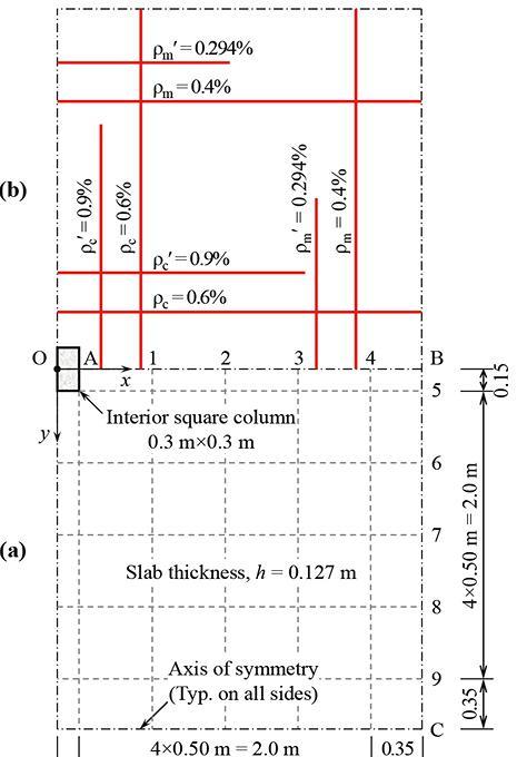
h = 5 inches (127 mm), supported on square columns of side dimension 11.8 inches (300 mm) with concrete compressive strength, f'c = 5.1 ksi (35 MPa) and typical interior and edge column-slab connections; the story height, lc = 9.83 feet (3 m). For seismic design, consider DRu = 0.018; where DRu is the ultimate story drift divided by the story height. This corresponds to an elastic drift, δe = 0.663 in (17 mm) (ASCE/SEI 7). Take the service gravity dead loads = ��h plus 20.9 psf (1.00 kPa) super-imposed dead load; with �� = 153 pcf (24 kN/m3); live load = 40 psf (1.9 kPa). Load factors and combinations in Section 5.3 of ACI 318-19 are used.
The effective depth of the slab is d = 3.74 inches (95 mm). In the current section, design rules of stud-rails with DG anchor heads (Dilger and Ghali 1981; Figure 2c), conforming to ASTM A1044/A1044M in ACI 421.1R-20 and ACI 421.2R-10 are applied at typical interior and edge columns. Figures 2a and 2b show the arrangement of the shear critical sections and the headed studs that ensure adequate punching shear strength at the interior and edge column connections, respectively. This design is adequate for an earthquke with an inelastic story drift ratio = 1.8%.
Shear stress at interior or exterior shear critical section, due to the transfer of factored shearing force, Vu combined with moments Msc x and/or Msc y is calculated by:

where Ac = bo d = area of shear critical section; bo = perimeter length of shear critical section; ��vx or ��vy = fraction of moment about x or y-axis that is transferred by shear stress at the assumed shear critical section; Jx or Jy = property of shear critical section equal to d multiplied by second moment of perimeter about x or y-axis; (x, y) = coordinates of point on perimeter of the shear critical section with respect to centroidal principal x and y axes. At edge columns, the centroid of the shear critical section does not coincide with that of the column, O; the slab moments, Msc x and Msc y about x and y-axis through the centroid of the shear critical section is related to the slab moments, Msc Ox and Msc Oy about x and y-axis through O by:
Vu = factored shearing force; (xO, yO) = coordinates of O with respect to the centroid of the shear critical section along the centroidal principal x and y axes. By elastic analysis of the frame in Fig. 3a subjected to gravity loads, determine the values of Vu and Msc Ox and/or Msc Oy; for seismic design, employ the equivalent frame in Fig. 3b.

The example slab has flexural reinforcement ratios, �� and �� ' in the column and middle strips as shown in Fig. 1b. During construction, the slab is subjected to a uniformly distributed load, qc = 133 psf (6.38 kPa); in service, the quasi-permanent distributed load on the slab is qp = 104 psf (5.00 kPa). The analysis procedure and equations are given in details in Ghali and Gayed 2019 and Gayed and Ghali 2022 (Chapter 6). The time-dependent material parameters are: t0 = 28 days; t = ∞; creep coefficient, φ(t,t0) = 2.491; aging coefficient, χ(t,t0) = 0.872; free shrinkage strain, ε cs(t,t0) = −300 × 10-6. Other data: moduli of elasticity of the concrete and reinforcing steel are: E c (t0) = 4.34 × 10³ ksi (28.0 GPa) and Es = 29 × 103 ksi (200 GPa), respectively; the concrete tensile strength, fr = 326 psi (2.247 MPa); Poisson’s ratio, v = 0.2.
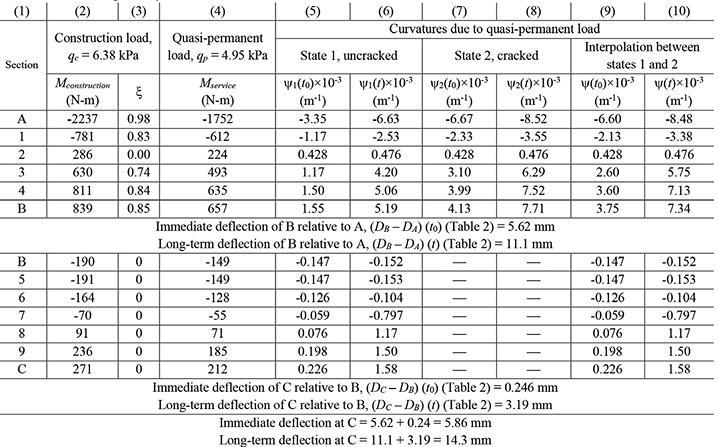
Note: Deflection at any intermediate point C on a beam can be evaluated numerically as: where Mu = bending moment due to a unit downward force at C. The summation is for all the beam segments. Mu and �� vary linearly over length of a typical segment with length = l and ends at a and b. (1 m = 1000 mm = 39.37 in. = 3.28 ft)

The computer program EGRID (Gayed and Ghali 2022) idealizes the flat plate panel as a grid of torsionless beam elements; the results of the analysis are in Table 1 (columns 2 and 4). Deflections at times t0 and t are calculated in Tables 1 and 2; the immediate and long-term deflections at Point C are 0.231 and 0.563 in (5.86 and 14.3 mm), respectively, corresponding to span/853 and span/350, respectively. For slightly longer spans, larger deflection can be counterbalanced by camber in the formwork.
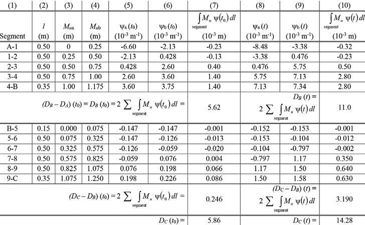

For the flat plate considered, ACI 318-19 requires a minimum slab thickness = ln/33 = 5.63 inches (143 mm). The code allows the chosen thickness 5 inch (127 mm) thickness because calculations showed its adequacy for the punching shear strength at the slab-column connections and the long-term deflection. Table 3 shows that the flexural reinforcements in Fig. 1b satisfy the flexural strength requirements under gravity and earthquake loads of the code.
The Canadian Cost Guide 2022 gives market value per square foot in Canada with common quality of finishing work in the range CAD $400-500, which is roughly US $300-365. With the optimum cost saving presented, the cost of the elevated structure per square foot can be reduced by 60 percent. If the cost of the elevated structure is assumed to be 25% of the total project construction cost, the overall saving to the project is 15%.
The DG anchor head at both ends of studs arranged in a crucifix layout in the vicinity of columns ensures punching safety. Current knowledge of creep, and shrinkage of concrete and relaxation of prestressing reinforcement is adequate to predict long-term deflection of floors.■
Ramez B. Gayed, MSc, PhD, PEng: Civil Engineering Consultant, and adjunct professor of Civil Engineering, University of Calgary, 986 Tuscany Drive NW, Calgary, AB, T3L 2T4, Canada (rbgayed@hotmail.com).
Amin Ghali, MSc, PhD, PEng: Emeritus professor of Civil Engineering, University of Calgary, Canada
Chandana Peiris, MSc, PhD, PEng: Principal at Avant-Struct Ltd, 6395 Ranchview Drive NW Calgary, AB (chandana@avantstruct.com).


