



subscriptions@structuremag.org
Chair John A. Dal Pino, S.E. Claremont Engineers Inc., Oakland, CA chair@STRUCTUREmag.org
Marshall Carman, P.E., S.E. Schaefer, Cincinnati, Ohio
Erin Conaway, P.E. AISC, Littleton, CO
Sarah Evans
Walter P Moore, Houston, TX
Linda M. Kaplan, P.E. Pennoni, Pittsburgh, PA
Nicholas Lang, P.E. Vice President Engineering & Advocacy, Masonry Concrete Masonry and Hardscapes Association (CMHA)
Jessica Mandrick, P.E., S.E., LEED AP Gilsanz Murray Steficek, LLP, New York, NY
Jason McCool, P.E. Cool Country Engineering PLLC,Cabot, AR
Brian W. Miller Cast Connex Corporation, Davis, CA
Evans Mountzouris, P.E. Retired, Milford, CT
Kenneth Ogorzalek, P.E., S.E. KPFF Consulting Engineers, San Francisco, CA (WI)
John “Buddy” Showalter, P.E.
International Code Council, Washington, DC
Eytan Solomon, P.E., LEED AP Silman, New York, NY
Jeannette M. Torrents, P.E., S.E., LEED AP JVA, Inc., Boulder, CO
Executive Editor Alfred Spada aspada@ncsea.com
Managing Editor Shannon Wetzel swetzel@structuremag.org
Production production@structuremag.org
Director for Sales, Marketing & Business Development
Monica Shripka Tel: 773-974-6561 monica.shripka@STRUCTUREmag.org
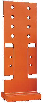


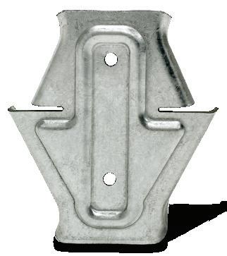


Simpson Strong-Tie provides comprehensive product solutions for commercial institutional construction. Whether you’re building an educational facility, healthcare center or public office, you can rely on a full array of products that are assembly-tested and proven for strength and versatility. From cold-formed steel and structural steel to adhesive and mechanical anchors, code-listed connectors and fastening systems, we have what you need to build safer, stronger structures. Our nationwide distribution network ensures product availability and timely jobsite delivery. Along the way, our expert field, technical and sales support teams are always ready to assist you. With Simpson Strong-Tie as your partner, you have a total solution designed to elevate performance. To learn more about our complete solutions for institutional construction, visit strongtie.com/institutional or call (800) 999-5099.

JPMorgan Chase’s new headquarters is the sixth tallest in New York City, reaching 1,388 feet.


Light gauge steel reaches new heights in an Oakland Residential Tower.
By Chuck KnickerbockerHigh-performance structural silicone glazing held to the steel frame of the three-story building provides durability and creates uninhibited sightlines.
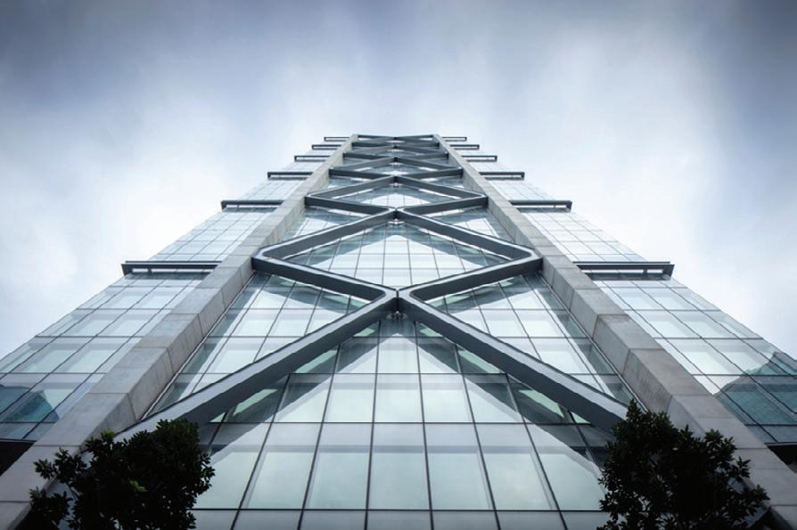
A new tower isn’t just transforming downtown Austin’s skyline—it’s reshaping the future of high-rise wind design.
SOM engineers are improving and adapting a structural system that revolutionized skyscraper design for a changed construction industry.




Ron Aquino, PEng; Shayne Love, PEng; and Jamieson Robinson, PEng
Russell Larsen, PE, SE; Farshad Berahman, Ph.D; Kevin Aswegan, PE, SE Dennis Pilarczyk, By Joe DiPompeo, PE


The Structural Engineering Institute (SEI) has long been committed to advancing structural engineering and promoting excellence in our profession. Recently, SEI underwent a strategic reorganization to better fulfill this vision, enhancing its ability to address pressing challenges and opportunities within the structural engineering field. Under a new strategic approach structure, the SEI Board of Governors identified four key focus initiatives: SE 2050 Commitment Program (SE 2050); Performance Based Design; Education and Leadership; and Young Professionals. SEI Focus Initiatives receive prioritized staff support, SEI resources, and Board of Governors promotion to accelerate the activities of each.
SE 2050 emerged in 2020 as a collective recognition within SEI of the urgent need to address the environmental impact of structural systems, specifically related to embodied carbon. SE 2050 is formally a response to the SE 2050 Challenge issued by the Carbon Leadership Forum (CLF) where SE was originally ideated. This call to action signified a bold commitment to steer the profession towards a sustainable future. SE 2050 aims to achieve carbon neutrality of structural systems by 2050, setting a precedent for transformative action within the structural engineering community. SE 2050 has evolved into a dynamic platform for innovation, collaboration, and knowledge exchange. SE 2050 facilitates a database with embodied carbon data of structural systems on real projects, fosters a community in which best practices in embodied carbon reduction are
shared, and provides key resources and tools. As SE 2050 celebrates its three-year anniversary, we are proud to say that it has helped empower structural engineers to navigate the complexities of sustainable design and construction.
SEI’s commitment to the success of SE 2050 aligns with the growing emphasis on embodied carbon tracking and reductions globally. There is little doubt that the total carbon emissions associated with buildings requires massive reductions in a relatively short time. Because most embodied carbon emissions from new buildings come from the structural system, structural engineers are uniquely positioned to spearhead the paradigm shift of holistically reducing the environmental impacts of buildings. It is imperative that we, as structural engineering experts, embrace this leadership role, driving forward the necessary changes to ensure a more sustainable and resilient future. There is no one better suited for this than structural engineers.
While the goal of achieving carbon neutrality by 2050 may seem daunting, it is critical that we embrace it wholeheartedly. The building design and construction industry is changing and will continue to do so with or without us—why not take control and ensure this rapid shift works for all structural engineers?
As structural engineers, we must step up. We must lead. There are far too many potential risks (and missed opportunities) of others leaning in and directing structural engineers on how to best integrate embodied carbon into our designs. Yes, it is challenging. We must deal with a seemingly continuous flow of competing priorities while upholding our ethical


responsibilities as professional engineers. Oh, and do it quickly. And under budget. Structural engineers are incredible professionals. We are more than capable.
SE 2050 was established to support structural engineers in their pivotal role. Through quarterly calls attended by 60-70 engineers from signatory firms, we foster a safe environment for sharing experiences and best practices, aiming to enhance understanding of the evolving Standard of Care and risk mitigation. Additionally, we offer guidance on material selection, publish real project case studies, and provide tools like ECOM for measuring embodied carbon. A key aspect of SE 2050 involves publicly sharing each firm’s Embodied Carbon Action Plan (ECAP). Over 150 firms have committed to sharing their annual commitment goals.
SE 2050’s commitment to transparency and data-driven decision-making is further evident in its efforts to publish embodied carbon data of structural systems on real projects. Our first data analysis was presented at the recent SEICon24 in San Antonio and is the start of our effort to provide invaluable insights, offering the only data-driven U.S.-based guidance on real trends and benchmarks of embodied carbon of structural systems. By sharing real-world data, SE 2050 enables structural engineers to make informed choices and drive meaningful progress towards carbon reduction. Our next in-development database will not only include the collection of embodied carbon but will also collect structural material quantities of structural systems to provide detailed insights into the efficient use of materials.
As structural engineers, we must embrace our role as leaders and stewards of the built environment, driving meaningful progress and guiding the profession towards a more sustainable and resilient future. Through initiatives like SE 2050, we as structural engineers can make a lasting impact that benefits both current and future generations. Have you joined the movement? Check us out at: https://se2050.org/. ■
We engineer building mass and stiffness but not damping, making it highly uncertain.
By Ron Aquino, PEng, Shayne Love, PEng, and Jamieson Robinson, PEngWe have been engineering mass and stiffness in tall buildings, but not damping.
When a tall building is subjected to a dynamic load, such as wind, seismic, or traffic, the structure is typically simplified to be represented as an equivalent spring-mass-dashpot system. In structural design, the mass and stiffness are normally “engineered” since these values can be directly calculated using material properties. When a structural engineer starts to size structural components such as beams, columns, walls, and slabs, the engineer is effectively selecting a mass and stiffness value for the individual component based on its geometry and material properties. Then by taking all components and defining their joint connectivity (fixed, pinned, or spring), the structural engineer is defining the global stiffness and mass characteristics of the structure, from which the system frequencies are determined.
While such mass and stiffness properties of structural materials are well defined, little is known about the damping or energy dissipation properties of materials. Damping is therefore a “non-engineered,” highly uncertain property that is assumed, rather than calculated, at the time of design. For simplicity in the design process, a global value for each mode of vibration is assigned based on experience with similar structures. For further simplicity, one damping value is generally used for all modes for a particular loading scenario. For example, a 5% damping ratio is typically used for each mode when performing seismic analysis. When calculating wind loads corresponding to the ultimate limit state, perhaps 2.5% damping is assumed for each mode. For service limit states, the ASCE 7-22 Commentary states that values between 1% and 2% are typically used in the U.S. while also referring to the ISO 4354 which suggests 1% and 1.5% for steel and concrete buildings, respectively. In practice, we have seen some engineers use anywhere between 0.8% to 2% for service conditions (including accelerations and wind-induced drift loads), and between 1.5% and 3% for Ultimate Limit State (ULS) wind load cases.
Research papers (e.g. Tamura et al, 2000; Bashor & Kareem, 2009)

have considered that the coefficient of variation (COV) of damping could be somewhere between 30% and 70%, whereas the COV of natural building periods or frequencies is no higher than 10%. The COV is the ratio of one standard deviation to the mean of a data set. A COV of 30% can be taken to represent a range of values from 30% below to 30% above the mean.
The structural design implication of a high COV for damping is significant. If 1.5% damping is typically assumed for the serviceability design of a concrete building, a COV of 30% means that it is reasonable to expect that the actual damping ratio could range between 1% and 2%. In terms of building accelerations, this implies a variation of ±20% from the expected acceleration if 1.5% damping was assumed in design. Such a variation is significant and would materially affect the motion comfort of the building and may also dictate if mitigation needs to be considered to reduce accelerations. Similarly, this variability of damping could also alter the wind-induced building drifts by up to ±20% from the expected value. If the damping variation were more than 30%, the variability or uncertainty in response quantities would increase as well. For wind loading, a proposal by Bashor & Kareem (2009) was made to effectively increase wind loads by approximately 20% on account of a 30% COV in damping, together with a 5% COV in natural frequency.
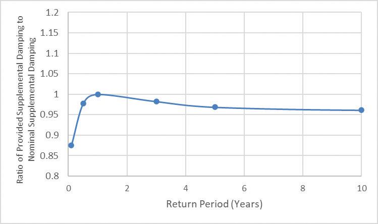
For the most part, the damping values used in design are based on full-scale measurements on completed structures. However, most measurements are conducted at very low excitation amplitudes compared to what the buildings are expected to experience during design wind events with return periods from 10 years or longer. Research in the 1980s (e.g. Davenport & Hill-Carroll, 1986) showed a somewhat linearly increasing trend of damping ratio with amplitude, with most of the measurements generally reporting damping below 3%. Note as well that these early measurements were likely done on buildings that were generally shorter than the tall, slender buildings we see more of in the present day. According to the Tall Buildings Database by the Council on Tall Buildings and Urban Habitat (CTBUH), there were only 13 “super tall” buildings as of 1990 (i.e. those that were taller than 300 meters). As of 2010, that number of super tall buildings was 49, and as of 2020, there were more than 100 super tall buildings. Research since the

1990s (e.g. Nakamura et al, 1993; Tamura et al, 2000; Cruz & Miranda, 2021; Xu et al, 2023) which is inclusive of tall (above 200m) to super tall buildings, has shown that the damping ratio can often be lower than what is typically assumed in design. Moreover, some research (e.g. Tamura, 2012) suggests that above a certain threshold of motion, the damping begins to decrease with increasing amplitude, suggesting it may be unconservative to use higher damping ratios for design loads. Motioneering, Inc. has measured inherent damping of completed buildings that is less than half of what was assumed during design for common wind events. Few research works (e.g. Aquino, 2013; Spence & Kareem, 2014) have investigated potential mechanisms behind this unusual trend of the amplitude-dependence of damping. However, if damping could increase and decrease with amplitude, such findings only beg the question, “what then is the appropriate damping value for design?”
Structural engineers can account for damping uncertainty by using more conservative assumptions, but this can have substantial financial implications for the project. Generally, a stiffer tower is required, which adds material costs and also decreases the useable space on each floor— undesirable consequences for any project. As engineers, the next question then that we might ask is, “Is it possible to engineer damping?” The
short answer is “yes”. In fact, this has been done before. In nautical, aerospace, and even automotive applications, some form of engineered damping devices are commonplace. In civil engineering structures, damping devices have been introduced to reduce the impact of high seismic demands. However, certain damping systems have also been demonstrated to control lower amplitudes under wind excitation to meet occupant comfort and serviceability criteria. However, for the most part engineered damping is not yet front-and-center at the design stage. Typically, the need for an engineered damping solution is not something discovered until after the preliminary building design has been carried out. Or worse, motion issues might be observed only after the building is built.
Two general approaches are used for an engineered damping solution.The first is a distributed damping system. Distributed damping has been widely used for decades in seismic applications where the amplitudes of concern (e.g. interstory drifts, building accelerations) are very high. Under low-level excitations associated with occupant comfort, such as under 1-month to 1-year wind loads, distributed damping systems may be constrained by internal friction mechanisms and system compliance that render them ineffective as a damping solution. The second approach is the use of mass damper systems, or dynamic vibrations absorbers, which employ a secondary dynamic system with its own mass, damping, and stiffness. These devices are typically used for wind response control, in which the motions are much smaller than seismic applications. However, mass damping


systems have been used to reduce both wind and seismic load effects. In general, distributed damping systems can be more easily integrated into architectural systems but have limitations when it comes to wind applications. Mass damping systems require space near the top of the building but can provide more reliable performance during service level excitation events. Having a mass damping system at one area of the building allows simplified coordination as it can be viewed as another building service alongside the HVAC, plumbing, fire, building maintenance units (BMU), and other similar services located on the roof or mechanical penthouse floors of tall buildings. In the succeeding discussion, the focus will be on mass damping systems for controlling the wind response of tall buildings.
Two types of mass damping systems are most used in tall buildings: tuned mass damper (TMD) systems and tuned liquid damper (TLD) systems. The main difference between the two is that TMDs employ a solid mass, while TLDs typically employ water as mass. Two common configurations of TMDs are discussed in the next section. TLDs require a tank to hold the water; however, it is the shape and size of the tank that determines its mass, damping, and stiffness parameters. TLDs can be further broken down into two sub-types: tuned sloshing dampers (TSDs) and tuned liquid column dampers (TLCDs). TLCDs generally act in only one direction, whereas TSDs can be designed to act in two directions. TLCDs generally provide lower supplemental damping than a TSD for the same amount of water. From experience, the authors have found that TLCDs are less effective than TSDs, and therefore do not recommend them unless specific space constraints require the use of TLCDs.
The simplest type of TMD system is the simple pendulum type. A classic example of this is the Taipei 101 TMD. A simple pendulum TMD involves the use of cables with a specific length to prescribe the frequency of the damping system. The solid mass in this case is of steel ballast material. Viscous damping devices (VDDs) are attached between the solid mass and structure to provide a certain level of internal damping. The TMD frequency, via cable length, and internal damping, via the VDDs, are initially selected to provide the optimum amount of damping based on textbook first principles assuming linear properties and simple excitation. However, for actual TMD systems, a performance-based approach considering nonlinear properties, particularly for the VDDs, and random excitations, based on more realistic input characteristics to simulate wind and earthquake loading, are used. Inherent friction in




the system should also be included in the simulations. The result is a sufficiently robust design that will provide a steady level of supplemental damping across a wide range of as-built conditions for the tall building. Full scale measurements are performed once the TMD is installed and tuned to demonstrate that the TMD performs as designed.
One downside of a simple pendulum system is that it could necessitate a very tall room due to the cable length requirement. For example, a tall building with a 6-second period requires approximately 30 feet of cable length—equivalent to about three stories. To account for variability in building frequency, this cable length may need to be increased to approximately 36 feet—equivalent to almost four stories tall. A solution has been developed and successfully implemented to resolve this issue: the use of an opposed-pendulum type of system. One example of this is the 111 West 57th TMD in New York City; some details of this TMD have been presented in a New York Times article. An opposed-pendulum TMD consists of a simple pendulum system attached to an inverted pendulum (a secondary mass suspended from the floor via steel columns). The TMD frequency is determined by proper configuration of the ratio between the two masses and the cable length and column height. For the 111 West 57th TMD, the required height of the TMD room would have increased four-fold had a simple pendulum TMD been implemented.
While opposed pendulum systems require the least amount of space, they do require slightly more engineering and higher costs. If space is not as much of a concern, especially if the required supplemental damping and therefore damper mass is not too high, TLD systems may be considered. However, only 60% to 80% of the water in TLD tanks actually participates as dynamic mass within the mass damper system. On one project, a 1000-ton TMD was required, but the client opted for a less expensive TSD alternative that, in the end, held nearly 2,000 tons of water!
On one project in Australia though, where the damper mass requirement was only in the order of approximately 200 tons, a TSD was the perfect solution for the client. An earlier consultant recommended a three-tank TLCD system, but by using performance-based design principles, constant coordination with the client, and full-scale building frequency measurements during construction, the project ended up employing just a one-tank TSD system that allowed the client to introduce a new penthouse apartment unit that more than made up for the cost of the TSD implementation. One key factor in the success of such a TSD design is that the water TSD tank was incorporated into the fire suppression water storage system. In short, the tank served dual purposes: as a TSD and as fire suppression water storage. During
commissioning of the TSD system, full scale measurements were done and analysis of the data reveal that the TSD is performing as expected. However, not all projects can accommodate a rectangular, box-shaped TSD tank. Again, as part of a performance-based design approach, coordination with clients reveals that only an irregular shaped tank can be accommodated in some projects. The numerical modelling used in the performance-based analysis and design of TSDs is verified using data collected from scale-model testing in the laboratory. For irregular tanks, the same approach is used. One project in China has used a triangular, wedge-shaped tank. Certain types of spire-like structures on buildings or on-ground have used annular-shaped (i.e. “donut-shaped”) tanks. On one super tall building in New York City, the building could only accommodate a tank that wrapped around the concrete core— effectively requiring a “square bagel”-shaped tank (i.e. a rectangle with a smaller rectangle cutout in the middle). By employing a performance-based design approach, it is possible to employ a wide variety of tank shapes that can still achieve the performance objectives.
Various damping technologies are available that provide a reliable level of damping, meet performance requirements, and fit within the project’s space constraints. Successful examples of TMD and TSD systems for wind response control have been implemented in tall building projects across the globe, where performance-based design principles were used and in-situ performance verification has been demonstrated.■
Full references are included in the online version of the article at STRUCTUREmag.org
Ron Aquino is a Senior Engineer for Applied Structural Dynamics with Motioneering, Inc. in Guelph, Ontario, Canada. He is a licensed professional engineer in Ontario, Canada and in the Philippines.
Shayne Love is a Technical Director for Applied Structural Dynamics, also with Motioneering, Inc. He is a licensed professional engineer in Ontario, Canada and in Michigan, USA.
Jamieson Robinson is a Vice President for Operations, also with Motioneering, Inc. He is a licensed professional engineer in Ontario, Canada.
Meeting seismic performance requirements in mass timber structures contains challenges and opportunities.
By Dong Han, PhD, Mohammad H. Mehrabi, MS, and Lori Koch, MS, PEThe past decade has witnessed an increasing adoption of mass timber buildings in North America. These innovative structures primarily feature large, engineered wood products, such as glued-laminated timber (glulam) and cross-laminated timber (CLT). Recognized for their sustainability, these materials align well with the growing emphasis on sustainable building methods. In addition to their environmentally friendly attributes, mass timber structures offer pleasing aesthetics and reduced construction timelines, setting them apart from conventional alternative materials.
Despite their advantages, mass timber buildings, as a new entrant, face design challenges that traditional construction methods have largely overcome during their decades-long evolution. Many of these challenges arise, in part, from a lack of prescriptive connection options, as well as testing and standardization of system solutions, for mass timber. Engineering costs may rise when additional time is necessary to design, specify, and detail custom solutions for every new mass timber project.
The 2024 International Building Code (IBC) references ASCE/SEI 7-22 Minimum Design Loads and Associated Criteria for Buildings and Other Structures for seismic drift requirements, with 2% being a common drift limit for Risk Category I or II structures. The most reliable method for quantifying the in-service drift performance of a given connection requires rigorous testing. Some municipal jurisdictions mandate cyclic deformation tests conducted at a drift of up to 4%, surpassing levels specified in national codes and standards. Significant challenges persist in accurately predicting drift performance for entire mass timber systems.
Common assumptions used in the design process may not always fully reflect real-world conditions, which can influence drift performance. In mass timber construction, most connections are modeled as pinned connections. In reality, these connections exhibit varying degrees of fixity, allowing them to resist rotation. As a result, factors like beam depth, lever arm length, and the gap between primary and secondary members can significantly influence connection performance. For example, the relative connector placement will influence the length of the lever arm created by the eccentricity between the extreme tension or compression face and the center of gravity of the connector. An increase in the length of the lever arm will intensify the prying effect

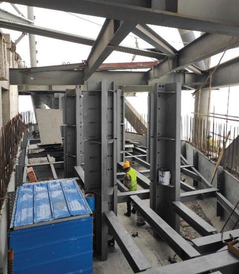
at the connection and could lead to undesired deflections or failure of the connection (Figure 1).
Moreover, seismic drift, in tandem with other considerations such as gravity loading and fire protection, plays a vital role in determining the ideal placement of the connector on the beam section that minimizes fracture development perpendicular to the grain under loading, especially in deep cross sections facing an elevated risk of cracking. Simultaneously addressing multiple concerns—a necessity in many cases—requires reinforcement, often achieved by incorporating reinforcing screws (Figure 2). While effective in many scenarios, this method has limitations.
In many current mass timber buildings, structural elements are linked through custom-made connectors—connectors designed based on the requirements specified in standards such as the National Design Specification for Wood Construction (NDS). The NDS design approach is generally considered conservative, often resulting in low material utilization efficiency. On the other hand, the present dearth of testing hinders a comprehensive understanding of real-world connector performance in various aspects, including capacity and seismic resilience. An increasingly common alternative involves the use of pre-engineered beam hangers (PEBHs), an off-the-shelf product whose performance has been validated through manufacturer testing. (Not all PEBHs are rated for seismic drift, and they should be carefully selected based on the manufacturer’s specifications.)
Through full-scale monotonic and quasi-static cyclic pushover testing, a study at Oregon State University examined the seismic performance of three beam-to-column connections: one employing a PEBH and two featuring custom solutions, a bearing plate and a notched column (referred to as PEBH, BP, and N connections, respectively) (Figure 3). Of these tested configurations, the PEBH can resist shear and axial forces, whereas the two custom connections only provide bearing support without lateral


capacity that is essential for transferring seismic forces. The PEBH consisted primarily of two aluminum connection plates and two clamping jaws connected via threaded rods. In each connection, a glulam beam with a CLT panel on top was connected to a glulam column using the respective connector. The monotonic and cyclic tests involved the use of a hydraulic actuator to apply a maximum lateral displacement of 10-7/8 inches and 5-1/2 inches, corresponding to interstory drifts of 7.2% and 4%, respectively.
The residual drift, or the permanent deformation, of a mass timber structure following a seismic event is a critical seismic performance metric for its connections. Under monotonic loading, the PEBH, BP, and N connections exhibited residual displacements of 5/16 inch, 3/4 inch, and 4-1/16 inches, respectively. A smaller residual drift generally indicates that the connector is more effective in restricting the permanent deformation of the connection, contributing to lower rehabilitation costs and improved occupant safety and comfort.
A load–displacement analysis, as shown in Figure 4, reveals two other crucial performance metrics, capacity and ductility. Of the three tested connections, the PEBH connection exhibited the highest load-carrying capacity, approximately 2.4 and 2 times that of the BP and N connections, respectively. (The significant drop in force at a displacement of approximately 4.4 inches for the PEBH connection resulted from the unloading and reloading of the hydraulic ram—used to simulate a gravity load—to prevent rotation.) All three connections displayed ductile behavior under loading. Compared to the custom connections, the PEBH connection delivered a significantly more pronounced initial stiffness, indicating a reliable and predictable linear and elastic performance prior to yielding, a desirable characteristic for mass timber connections. Cyclic testing facilitated an understanding of the capacity of the three connections to dissipate energy. A high capacity to dissipate seismic
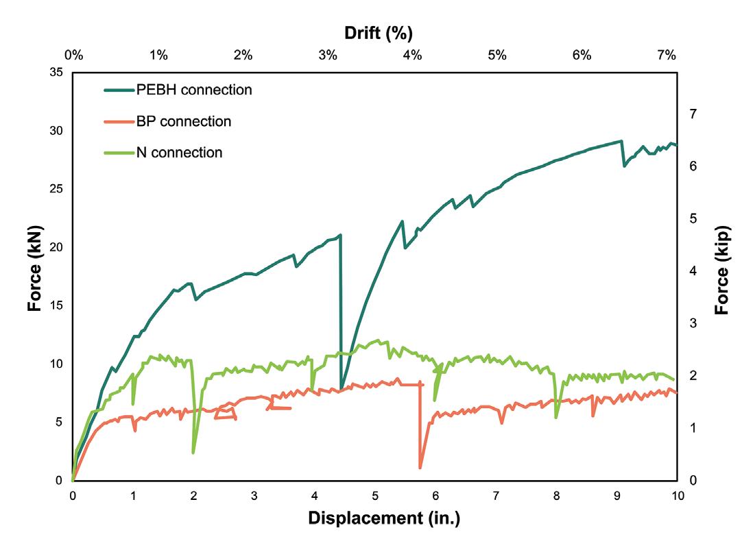
energy is generally preferable, as it contributes to the reduction of vibration energy. In comparison to the two custom connections, the PEBH connection gradually dissipated more energy per cycle as the testing progressed, ultimately dissipating the most energy, as illustrated in Figure 5.
As mass timber buildings continue to gain traction across North America, including its seismically active zones, the limited guidance on the seismic performance of connections designed based on NDS provisions raises challenges in determining if code-specified drift targets


are being met. Codified prescriptive options with tested or established performance have not yet been widely developed in the industry, and custom-designing bespoke connections for every new project adds project costs. Mass timber connections can generally be established using either custom-designed connectors or PEBHs. Monotonic and cyclic testing has suggested that PEBHs can deliver seismic performance comparable to, or better than, that of custom solutions, particularly in terms of capacity, ductility, and energy dissipation. PEBHs are an attractive option that can be considered not only for their proven structural performance but also their value-engineering benefits. ■

Dong Han, Ph.D, studied advanced materials for environmental, medical, and energy applications and has been involved in the scientific publication industry for a decade. He is a Senior Scientific Writer with MTC Solutions, a firm providing tested and hardware solutions, as well as assistance in designing cost-efficient connecting systems for mass timber projects.
Mohammad Hossein Mehrabi, MS, is a Structural Product Application Engineer with postgraduate degrees in earthquake engineering. He serves as an Engineer in Training at MTC Solutions, specializing in Product Design.
Lori Koch, MS, PE, is a Senior Product Engineer with MTC Solutions. She is a board member for SEAVa, serves on the NCSEA Continuing Education Committee, and is a licensed Professional Engineer in Virginia (support@mtcsolutions.com).
From landmark skyscrapers to long-span bridges, our team has designed and delivered performance-based damping solutions for over 25 years, enabling buildings and structures to be more ambitious than ever before.

Advancements in wind-supplemental dampers allow engineers to build taller and safer high-rise buildings.
By Russell Larsen, PE, SE; Farshad Berahman, Ph.D; Kevin Aswegan, PE, SE
"Trust, but verify!”
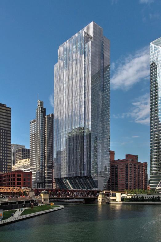
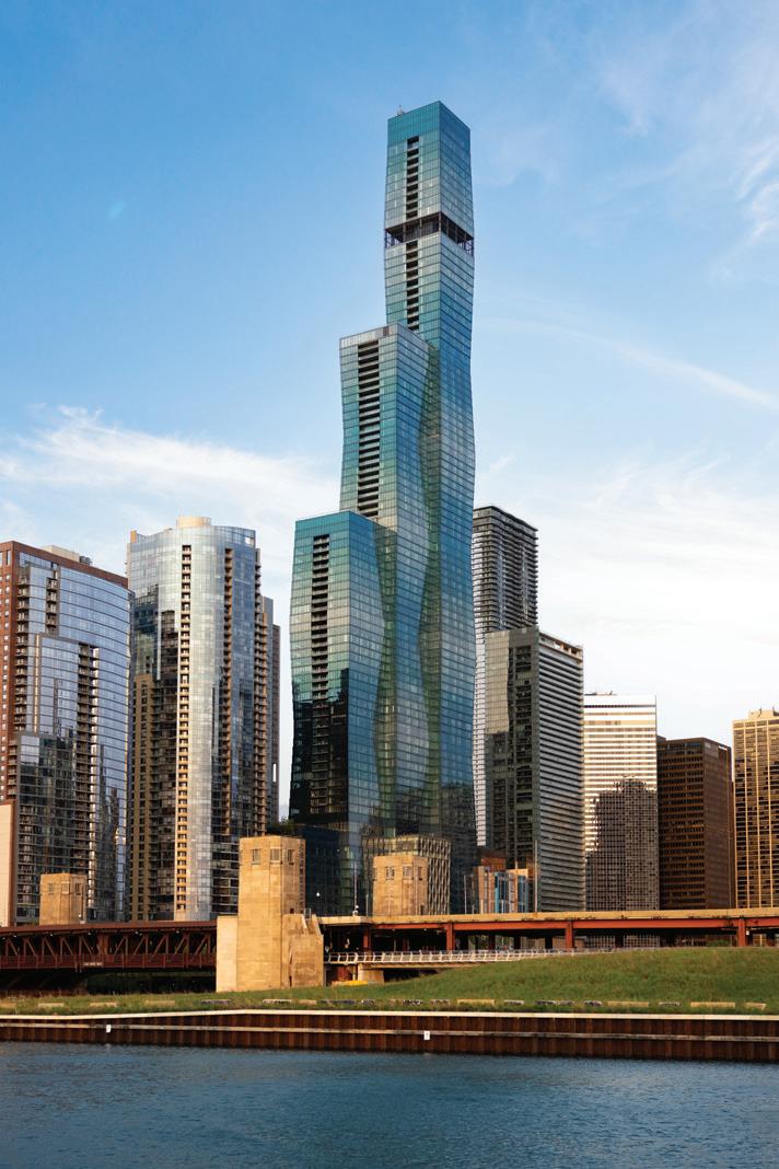
Russian proverb or political saying aside, how often do engineers look back and confirm whether their designs have achieved their objectives? For the structural engineers at Magnusson Klemencic Associates (MKA), asking and answering this question was top of mind given their design of four notable office and residential towers between 2014 and 2020—Seattle’s Rainier Square and Chicago’s 971-foot-tall One Chicago, 1,198-foot-tall St. Regis, and 752-foot-tall 150 North Riverside.
These towers are similar in height and wind sensitivity, and engineers needed to supplement wind performance beyond base code requirements. Like Chicago, New York, and many other cities, Seattle experiences wind events strong enough to buffet and flex high-rise buildings—a challenge for engineers striving for new achievements in building height, efficiency, beauty, and sustainability while offering safety and structural sturdiness during extreme winds. After completion of MKA’s wind-related design for downtown Seattle’s 58-story, 850-foottall Rainier Square tower, the firm revisited its projections to verify design objectives were met, ensuring performance and bolstering confidence in their ability to design the next generation of high-rise towers safely in windy regions.
Rainier Square is the world’s first high-rise to incorporate the exceedingly strong and stiff American Institute of Steel Construction’s SpeedCore lateral system into its structural design. Rainier Square’s design accounted for the site’s constrained land-use setbacks, development-area limitations, an aggressive construction timeline, and a slender and prismatic upper series of floors.

Early design wind studies carried out by structural wind tunnel testing consultant Rowan Williams Davies Irwin (RWDI) revealed the challenges of delivering satisfactory wind performance at Rainier Square. Built in a seismically active region of the United States, the Performance-Based Seismic Design tower’s square-shaped upper floors also experience notable vortex wind forces at one- to 10-year strength windstorms, the time range at which wind motion for occupants is most critical. Therefore, the seismic design needed to reflect member sizes within the lateral force-resisting system from results provided by wind tunnel-based testing and loads.
With the wind tunnel test findings confirming the need to manage wind motions, the team of the designer, owner, and builder began assessing options:
Structural Stiffening—This option proved too expensive and/or was unhelpful to seismic design.
Reshaping/Adding Exterior Wind Disruption
Features—This option did not serve the architectural desires, the usable floor-plate areas, or the setback realities of the constricted sites.
• Supplemental Damping—MKA adopted this option, with tuned liquid sloshing mass dampers managing Rainier Square’s motion on windy days. These dampers proved more cost-effective than bespoke mechanical mass pendulum dampers, distributed viscous dampers, and other similar options. Additionally, the owners and contractors were confident that existing jobsite crews could construct and waterproof the damper tanks.
As the project progressed, MKA’s engineers were eager to see if earlier building analyses and wind tunnel findings would materialize in the real-world monitoring data. The first step was to monitor the development of the sway periods during the tower’s construction. Historically, accelerometers detecting ambient accelerations were bulky, expensive, or delicate. Today, economic data collection is possible in real time thanks to Epson’s off-the-shelf microcomputer parts and accelerometers. (See sidebar.)
The accelerometers were deployed to the tower about when the tower reached half its total height to monitor the ambient lateral accelerations caused by day-to-day winds at Rainier Square. Frequency analysis of this data revealed the sway periods. Perhaps without surprise, due to the robust nature of SpeedCore, building sway period predictions closely matched collected data.
In the months and years after completion, tower monitoring at Rainier Square has continued. Several summer and winter seasons have been observed, including large and small windstorms in Seattle. Acceleration readings have been and continue to be collected. Daily, MKA engineers receive a summary of building performance versus Seattle wind-speed data published by the U.S. National Oceanic and Atmospheric Administration (NOAA).
MKA compares these peak accelerations collected against wind gust data of the same date and time at Rainier Square. Specifically, acceleration and wind speed data are grouped into successive three-hour blocks. From each block, the peak acceleration and wind speed data are collected from the NOAA network; plotting these acceleration points (vertical axis) with wind gust points (horizontal axis) results in the information shown in Figure 1. Data highlights collected at Rainier Square reveal the following:
• Acceleration Trends—The blue points in Figure 1 represent the observed storms in 2021 through mid2023. The solid black line represents the performance expectation established by wind tunnel testing. The results indicate Rainier Square performs as expected. Specifically, accelerations trend at or below the design predictions, as evidenced by the points below the predicted response line.
• Large Windstorms—The fewer count of points on the righthand side of Figure 1 illustrates the rare nature of large windstorms. In two-plus years of monitoring, only two relatively large storms occurred: one with slightly less than a one-year recurrence interval and one slightly


above the one-year recurrence interval. Neither storm exceeded the performance criteria established during wind tunnel testing.
Figure 1 offers a view of how Rainier Square responds to the wind but omits several interesting facets of the collected data—namely, the building acceleration collected in both axes and building movement (e.g., NorthSouth movement versus East-West movement). MKA considered how data for building directional accelerations versus the direction of wind approaching the building could be visualized and explained simultaneously. In response, Figure 2 was generated, confirming what long-time Seattle residents know—strong and common winds often come from the southwest, or occasionally the north. Furthermore, NOAA data also includes both wind speeds and the directionality of those gusts.
So, what does Figure 2 really tell engineers? Firstly, the diagram includes all the same data from Figure 1 but expands upon it by including approach direction and gust wind speed—with the diagram set up as a compass showing North, South, East, and West directions overlaying the aerial view of Rainier Square tower. Within this compass orientation, the data points from Figure 1 are now positioned as gust wind points around the center with concentric circles indicating gust speed (the further the distance from plot center, the greater the wind gust speed). The overall magnitude of acceleration is then represented by the color of the dot, which is measured in increments of milli-g in the legend—a milli-g being 1/1000th of a “g” or the force of gravity. The relative magnitude in the building X versus Y axis is represented by the length of the whisker lines at select acceleration events.
To further explain, a single circled data point has been identified in Figure 2. This data point communicates the following information:
• Wind gust speed = 45 miles per hour.
• Position within compass shows wind coming from the West Southwest direction.
• The color denotes the peak acceleration within this
storm—gray, or 3 to 4 milli-g, in this example.
• Whisker lines show a longer Y axis than X axis, meaning the building is moving more in the along-wind direction.
• This point is also identified in Figure 1 as the “individual storm.” With all of this collective data plotted and considered overall, several interesting trends emerge from Figure 2:
• Most notably, wind gusts do, in fact, originate from the Southwest (as predicted by the wind tunnel climate models).
• Winds tend to cause across-wind accelerations on par with alongwind accelerations (as predicted by the wind tunnel data and shown in the whisker lines).
• Winds from the North can generate greater "across-wind acceleration" (building X direction), which is consistent with the prediction of the wind tunnel.
• Southwest-approaching winds hitting the flat face of the tower are the source of the most common building response motions— motions which can be along-wind or across-wind.
Micro-Electro-Mechanical Systems (MEMS) technology provides highly sensitive accelerometers at a fraction of the size and cost of former accelerometer technologies. MKA engineers assembled in-house sensing systems using an Epson M-A352 three-axis accelerometer controlled by a Raspberry Pi (a $35 computer developed to educate children). A simple Python code provides sensor control, records data to memory, and reports that data to MKA offices through a cellular Wi-Fi/ internet connection. The entire assembly fits within a shoe-sized box and is easily placed out of the way on a construction site.
Given the real-world experience and verified results of Rainier Tower, the data collected furthers the clear path to better and safer high-rise design. As previously mentioned, from the onset of the design of Rainier Square, several wind motion solutions (as well as damping technologies) were considered once it became clear that the wind response would challenge the design. Damping is not the only method to manage wind response. Alternatives to mitigate motion, as described above, include adding mass, where a more massive building accelerates less when pushed by the wind, or adding stiffness, where a stiffer building moves less when pushed by the wind. But each of these options comes with additional costs, as more material equates to more money and, indirectly, can hamper seismic design when larger lateral force-resisting system structural members are required for wind resistance, which in turn elevate the member and connection

forces observed during seismic design.
Once the stiffness and added mass “brute force” solutions were off-thetable for Rainier Square, three damping technologies were considered: a sloshing damper, viscoelastic dampers, and a tuned mass damper. In the end, a sloshing damper was chosen. Sloshing dampers operate similarly to a traditional tuned mass damper, but instead of a steel or concrete mass swaying from a cable or mechanical assembly, the natural sloshing of water within a storage volume provides both the damper mass in the form of the water’s weight, and the damper tuning by controlling the sloshing rate of the water. Specifically, in tuned liquid sloshing mass dampers, the water’s depth versus the tank’s length establishes the frequency, or rate, at which water will naturally move from one end of the tank to the other. When properly tuned, a sloshing damper uses water to counter the sway of the building. As the building moves left, the water sloshes up the tank’s right wall. The difference in water pressure between the right wall (higher pressure) and the left wall (lower pressure) creates a net force to the right, thus pulling back the building.
While sloshing dampers have been applied to buildings for at least 25 years, designs before the mid-2000s involved building a scale model of the tank and subjecting it to the expected motions of the wind. Much of this work was carried out at the University of Western Ontario. One of the researchers, Dr. Michael Tait, went on to develop and publish methods that allowed designers to calculate the necessary tank system’s length, width, water depth, and internal baffle parameters. MKA’s engineers applied Dr. Tait’s approach in the initial sizing and final designs for Rainier Square. In the end, implementation of sloshing dampers carried the day at Rainier Square due to the available rooftop space, the relative advantage of the “simple construction” of a waterproofed concrete box, lack of long-term maintenance, and the reduced lead time compared to the bespoke fabrication of other damper technologies.
Humans can sense motions around them, and when standing, undue horizontal motions of the building can cause an occupant a sense of unease, vertigo, or even imbalance when walking or standing. The detectable horizontal acceleration of most people begins at 0.004 of gravity acceleration, g. This is a very small horizontal acceleration threshold, so engineers generally discuss acceleration in 1/1000 g units, or milli-g. Notably, industry documents such as ISO 10137 include horizontal acceleration performance targets to reasonably manage the disruption to building occupants due to motion. Those targets range between 4 and 8 milli-g for most building types.
Engineers deeply trust researchers, code writers, and consultants that they partner with, support, and look to. Seeing the mathematics, methods, and engineering, confirmed strongly in real-world completed projects, is refreshing. As evidenced by Rainier Square and four other similarly tall and damped towers currently monitored by MKA, wind tunnel testing and advancements in supplemental damping allow engineers to build towers that achieve new standards for height, efficiency, beauty, and sustainability while offering safety and structural sturdiness during extreme wind events. ■
Russell Larsen, PE, SE, is a Principal at Magnusson Klemencic Associates (MKA).
Farshad Berahman, Ph.D, CEng, MIStructE, is a Senior Principal at MKA.
Kevin Aswegan, PE, SE, is a Principal at MKA.




See how high-strength steel is enabling sustainable design. nucor.com/madeforgood


JPMorgan Chase’s new headquarters is the sixth tallest in New York City, reaching 1,388 feet.

The new corporate headquarters for financial giant JPMorgan Chase, at 270 Park Avenue in Manhattan, became New York City’s largest steel building when it topped out in November 2023. Located in midtown Manhattan on a full block bounded by Park Avenue to the east, Madison Avenue to the west, and East 47th and 48th Streets to the south and north, the building encloses 2.5 million square feet spread over 60 floors and reaches a height of 1,388 feet, making it the sixth tallest in the city. After extensive study, JPMorgan Chase chose the site despite the presence of its former headquarters on the east half of the block, a 50-story building originally constructed for Union Carbide and completed in 1960. The older building was intended for only 3,500 employees, a quarter of the number Chase might eventually house in the new building. Furthermore, the building’s close column spacing and low ceiling
heights were not conducive to modern office layouts. The potential for a large footprint, central location, and connections to public transportation, among other benefits, outweighed the effort involved in demolishing the existing structure.
Now fully utilizing the entire 200-feet by 400-feet block, the new building will provide more than twice the ground-level outdoor space, including an expansive public plaza and street-level green spaces. An open and spacious two-story lobby affords views through the building from Park to Madison Avenues and makes the office tower appear to float above. Architecturally, the tower is like a row of nine books—rectangular extrusions of the longitudinal column bays—aligned on a shelf. Each book is a different height: The east- and west-most column bays terminate at intervals, creating symmetrical stepped roof setbacks. From the highest setback to the peak, the building is only 40 feet wide.
The most significant challenge to building on the site is the presence of Grand Central Terminal and the recently opened Grand Central Madison beneath all but the western quarter of the site. The terminal’s tracks run north and south and are typically paired with a platform between them—an east-west spacing of about 60 feet—leaving only the narrow gap between adjacent tracks for the foundation for the new building. Worse, the structure supporting the trainshed roof and the Union Carbide Building occupies much of that gap.
Still, the design team, led by architects Foster + Partners and structural engineers Severud Associates, rose to the challenge. Working closely with the Metropolitan Transportation Authority (MTA), which operates Metro-North Railroad and Long Island Rail Road, the team examined the space between dynamic envelopes—often no more than 48 inches wide—taking into account existing power, signal, and other utilities that could not be interrupted or relocated without prohibitive cost. Only a few lines of potential bearing were identified, and along them, only a handful of locations were found practical.
The west quarter of the site—a roughly 100 feet width along Madison Avenue—is much less obstructed than the Park Avenue side. It has more direct support on bedrock, which gave the designers greater flexibility and a convenient place to locate the building’s service core. Additional columns could have also been located here; however, the architects desired an externally symmetrical design. Therefore, column locations were chosen that mirrored the supports along Park Avenue.
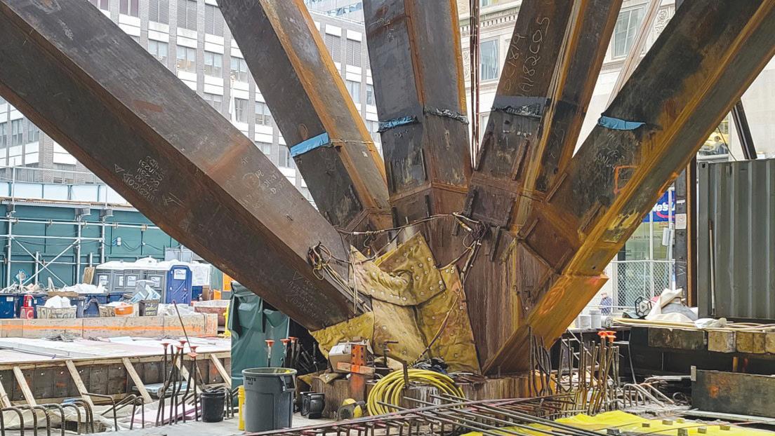
Collecting the gravity and lateral loads from the tower columns— spaced at 40 feet east to west and up to 66 feet north to south—and delivering them to the selected points required an extensive transfer system. The architects and engineers studied several framing alternatives before arriving at a two-story-high arrangement of steel transfer girders and sloping super-columns and braces that came to be known as the Tabletop.
Along the north and south elevations, groups of four adjacent exterior columns slope inward and toward each other to create three fan-shaped sub-structures. Longitudinally, two 25-feet-deep plate girders span the full length of the building—360 feet—to transfer the interior columns. The girders, which also carry the second and third floors, are each supported by V-shaped columns. Together, the girders and columns form two vertical planes down the center of the structure.
Supplementing the fan and V columns are six diagonal macro-braces. At the east end, members slope upward and outward from the base of the easternmost fan columns to a point midway between the east ends of the transfer girders. At the remaining fan column bases, members slope upward and inward to the top of the transfer girders.
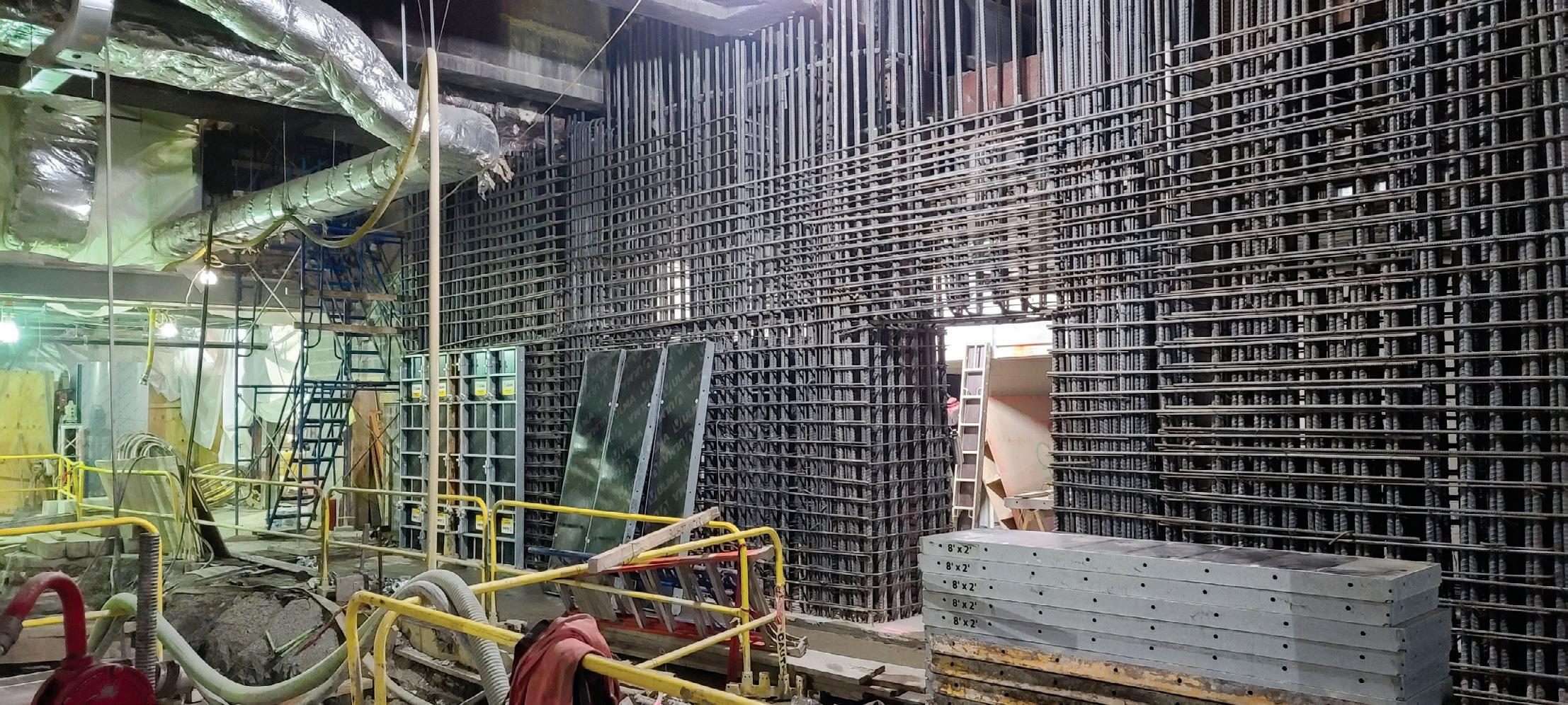
Despite presenting an elegant and lightweight appearance, the Tabletop puts tremendous demands on its foundation. The loads at the base of each super-column are almost 100,000 kips, while the area available at each support is only about 60 square feet. Steel base plates accommodate the bearing pressure directly beneath the columns, but below ground level, construction was constrained by two levels of railroad tracks as well as the MTA’s desire to protect the trainshed roof and minimize track outages.


The design team concluded that a concrete solution was needed to create a path through the existing trainshed and down to bedrock. The concrete had to be stronger than the 14,000-psi mix successfully used on Severud’s One Vanderbilt Avenue project nearby. Higher strength concrete mixes were not readily available, so the design and construction team set out to develop one. Severud, along with foundation contractor John Civetta & Sons and concrete supplier SRM Concrete, engaged in a series of trial mixes, laboratory testing, and full-scale mock-up placements. The first step was determining the concrete mix proportions. Cylinders were cast using different combinations of cement, blast furnace slag, fly ash, and microsilica, and tested for strength. After many iterations, the team arrived at a reliable and affordable
concrete mix with a 56-day compressive strength of 16,000 psi. As a bonus, the cement content is only about a third of the total cementitious material, reducing the concrete’s carbon footprint. With the strength issue resolved, the team turned its attention to placement concerns. Given the limited accessibility and the heavy reinforcement that was needed, getting the concrete into the forms without affecting its properties was of great importance. Mock-up panels of the 48-inch-thick piers were constructed, 8 feet wide by 8 feet tall with multiple curtains of heavy reinforcement. Concrete was placed in the forms using a pump with 100 feet of hose and from a height of 40 feet to simulate how it would be placed in the field. At 3, 7, 14, 28, 56, and 90 days of curing, cores were drilled from the mock-ups and tested for strength; the results were within the same range as lab-cured cylinders.
The mock-ups were also used in a parallel study of temperature effects. Due to the high cementitious material content, hydration produced elevated temperatures. Thermocouples were installed throughout the test panels to monitor the concrete’s temperature near the surface and at depth. Methods to attenuate the effects were explored, such as embedded water pipes for cooling, but most were found impractical. Eventually, the team determined that spraying liquid nitrogen—at minus 320°F—into the mix during batching cooled it sufficiently— typically, to a maximum of 58°F—to remain dormant (an inert element, nitrogen vaporizes and dissipates with no permanent effect on the concrete). Once placed, the concrete began to warm but monitoring revealed that during the first 72 hours of curing, the concrete temperature remained well below a calculated maximum of 186°F. Further, the differential between the surface and core temperatures never exceeded 35°F.
Although development of a 16,000 psi concrete mix presented several practical issues, careful study resolved all of them without penalizing code requirements, workability, cost, and schedule, and ultimately resulted in consistency in the final strength. In fact, by the end of the project, testing of more than 7,600 cubic yards of concrete revealed an average strength closer to 20,000 psi and a maximum strength of 23,000 psi, setting a new standard for high performance concrete.
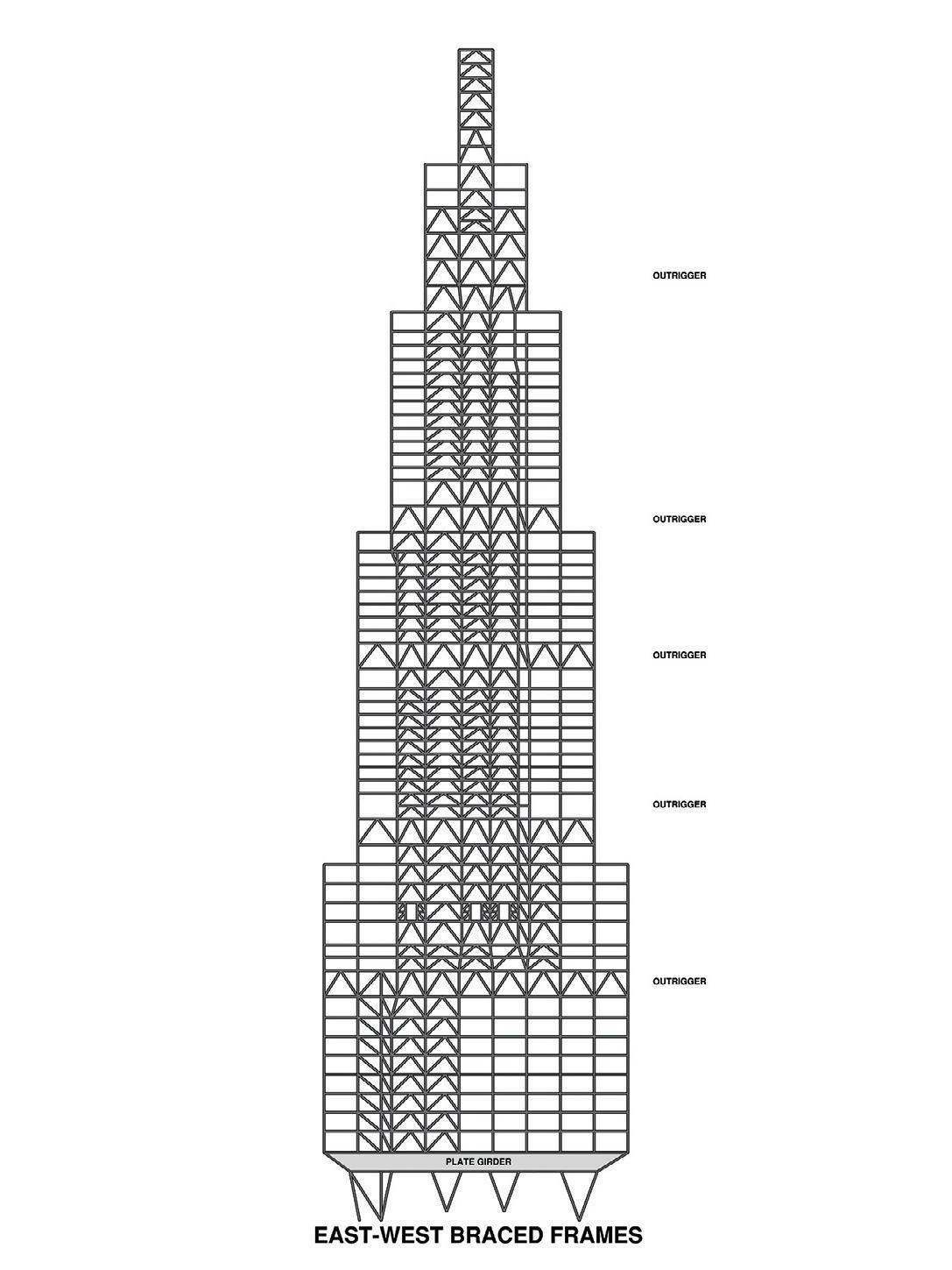
The structurally elegant lateral system for 270 Park Avenue consists of five parts: the ground floor and walls below; the Tabletop; the braced tower core; five levels of outrigger trusses; and the exterior macro-braces, which are configured in a distinctive diamond shape on the east and west facades. Working together, the core, outriggers, and macro braces carry the horizontal shears and moments from the superstructure to the Tabletop. The Tabletop—which acts as a space truss with rigid top
chords—transfers the loads to the ground floor.
In the north-south direction, the braced core and outriggers work in conjunction with the exterior diamond frames to provide the lateral resistance and a smooth drift curve. The outrigger trusses distribute lateral-induced vertical forces to the spandrel columns, increasing the effective width of the system. At ground level, the core and Tabletop braces deliver loads directly to the supporting concrete walls, even those located between train tracks. With few closely spaced supports, however, the uplift forces generated are extremely high—on the order of thousands of kips.
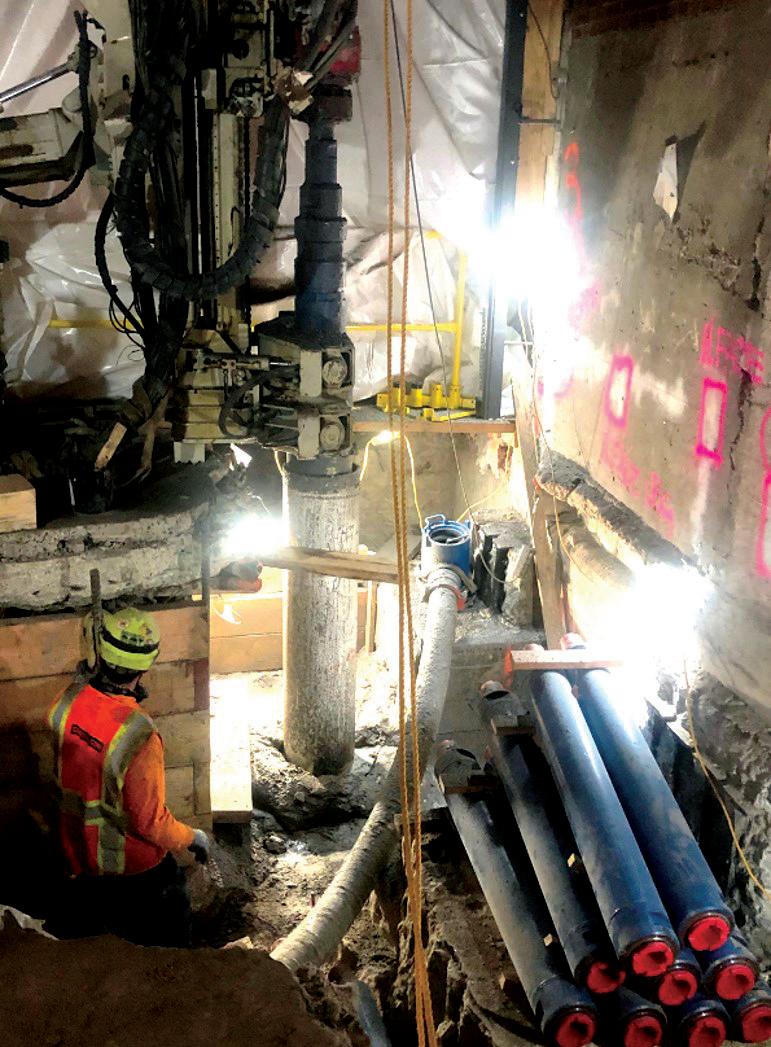
The foundation walls are supported by 13.5-inch diameter caissons, drilled into bedrock from the lowest track level. For uplift, the caissons are post-tensioned with three No. 32 (4-inch diameter), Grade 75 threaded bars. The traditional approach to anchoring the column bases—two levels above the foundation—is to install prestressing tendons from the caisson cap or the bottom of the wall and post-tension them from the ground level. The design team chose this route, but with an ingenious turn.
Concerned that a failed dead-end anchor might not be repairable or replaceable at track level, engineers devised a system of U-shaped ducts for the tendons, with both openings at ground level, that dip to the bottom of the caisson cap to engage the rock anchors. After proving the concept with the full-scale pier mock-ups, tendons of 27 strands each were fished through the ducts, passed through holes in the massive column base plates, and tensioned with a jack at each end, working simultaneously.
In the east-west direction, spandrel beam offsets to accommodate the curtain wall on the north and south facades prevented significant utilization of moment-resisting frames. Consequently, all lateral load is collected in braced frames located on the north and south sides of the office core. Again, outrigger trusses were placed at mechanical floors along the building’s height to engage the spandrel columns and increase the effective width of the frames.
Above the 14th floor, all the elevator shafts shift eastward from Madison Avenue to the center of the floor plate in a more traditional layout. Here, the multiple-floor transfer, known as the sky lobby, creates a livable space at the center of the building with a conference center and

recreational facilities. The outrigger trusses at the 11th floor redistribute lateral loads from the terminated core bracing along the length of the Tabletop plate girders.
Train tracks and platforms prevent the transfer of lateral load from ground level to foundation. As a result, the ground floor slab over the trainshed is used as a gigantic drag strut to deliver the lateral forces from the columns bearing over the trainshed to the western portion of the foundation. The 16-inch thick slab has a concrete strength of 10,000 psi and is post-tensioned with four groups of four tendons aligned with the column bases.
The tendons, each composed of 55 strands that required specialized jacks from France to be tensioned, are anchored by the cellar walls and ground floor slab at the west quarter of the site, a portion of the building that the design team refers to as “terra firma.” Due to the tremendous shear stresses, the slab is 36 inches thick, with a strength of 10,000 psi and post-tensioning in both directions.
The response of the building to wind loads, especially at service levels, was an important component of the structural design. Severud worked closely with wind engineering and micro-climate consultant RWDI to develop performance criteria and confirm that strength and serviceability targets were met. RWDI engineers performed detailed wind tunnel testing and multiple rounds of analysis to determine the wind-induced structural responses in each principal direction and in torsion.
Using the wind tunnel data, dynamic properties of the structure, and a statistical wind climate model for New York City, they predicted peak accelerations and torsional velocities for one-month, one-year, and 10-year recurrence interval events. Initial analysis of the lateral system response to these events revealed that accelerations at the uppermost occupied floors would exceed the targeted comfort levels without attenuation.
With additional study, the team determined that a pendulum-type tuned mass damper, sitting on the 54th level and suspended on 46-foot cables anchored two floors above to the framing of level L55M, would effectively control building accelerations. The 280-ton damper will keep wind-induced accelerations within the desired comfort levels—below
those typically applied to residential buildings—for one- and 10-year wind events. The damper is also expected to provide a 10 to 15 percent reduction in drift for wind events with a mean recurrence interval of 10 years, and a 5 to 10 percent reduction for a 50-year return period.
Wind loads are not the only sources of vibration at 270 Park Avenue. The building shares its foundation with two dozen railroad tracks, therein subjecting it to intense excitation with each passing train. At minimum, several trains pass beneath the building every hour, and even more during rush hours. Severud engineers worked with RWDI to tackle the vibration demand, starting by developing an extensive vibration monitoring protocol and an initial input forcing function. Using an analytical model of the Union Carbide building, the trial forcing function was applied and its response predicted. The modeling accounted for the subgrade modulus of the supporting rock, the travel path of vibrations from the track support framing to the building foundation and up through the building columns, and the proportion of the building mass participating in the response.
Analysis predictions were then compared to measured responses in the building. Using the observed measurements, the input forcing function was recalibrated accordingly and re-applied to the analytical model. After more than 150 iterations, a forcing function that produced responses in good agreement with measured vibrations was established and used as input to an analytical model of the new building to assess its anticipated vibration performance. Subsequent field measurements in the new building revealed a response to train-induced vibrations suitable for sensitive lab equipment at the ground floor, with significant reductions up through the tower.
Collaboration between Severud, construction manager AECOM Tishman, and steel contractor Banker Steel—based on close relationships strengthened during their work together on One Vanderbilt Avenue—led to significant improvements in the structural steel fabrication and erection. This was especially true for the Tabletop, a complex sub-structure that posed several logistical challenges and created the critical transition from foundation to office tower that made the project possible.
Tabletop connections, where at each node up to five massive members converge at a single point, benefited greatly from the steel contractor’s involvement. The conventional approach is to create nodes using welded plates, but that presented daunting constructability issues, mainly due to large, multi-pass welds and the likelihood of heat distortion. The potentially unfavorable aesthetics of the exposed connections were an additional liability.
Instead, the team proposed nodes fabricated from forged steel to reduce fabrication issues and better accommodate the threedimensional stress field acting on the nodes. It is a brute force solution—the forgings are essentially huge blocks of solid steel—as well as a sophisticated one. Using the results of advanced finite element modeling that determine detailed 3D stress distributions, metallurgists at fabricator Ellwood Specialty Steel chose an appropriate alloy and proscribed a process of heat and mechanical treatments to fabricate weldable nodes that safely transmit high stresses on multiple axes. The plate girders that form the backbone of the Tabletop are the building’s largest single elements. Spanning the length of the building, the plate girders are 25 feet deep—the full height of the second floor. Their flanges are 5 feet wide and up to 8 inches thick and their webs up to 6 inches thick. Due to their immense size and stiffness, deflection of the plate girders is negligible and cambering was not necessary.
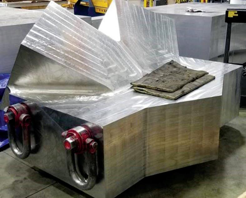
Their total weight is on the order of 1,800 tons each, so the girders were divided depthwise into three stacked sections that were fabricated in lengths that could be shipped upright, lifted into place, and field-bolted together. Many web penetrations were needed for doors and mechanical systems. The larger openings—greater than half the depth of the section—were only partially cut in the shop to maintain stability during transport. Once erected, the cuts were completed and the waste removed.
The erection plan developed by AECOM Tishman and Banker was perhaps most instrumental in the timely construction of the Tabletop. The transfer system’s two longitudinal girders and rows of fan columns create three natural east-west traffic lanes through the site. Banker Steel placed crawler cranes in the north and south lanes, which could pick up and place members delivered via the center lane via Madison Avenue—the only delivery access allowed.
Temporary elevated runways and a protection platform were designed and installed starting at the west and progressing east. Working independently, the cranes erected the fan columns; working in tandem, they erected the transfer girders and then the framing between the girders. This allowed erection to begin while demolition of the Union Carbide building and construction of the foundation walls were still in progress. By the time the cranes reached mid-block, demolition and foundation work had been completed and the cranes continued east to Park Avenue. From there, they backed out the way they came in, erecting the framing between the fan columns and transfer girders and setting the four tower
cranes that would erect the remainder of the building. Above the Tabletop, steel erection proceeded as if for a typical building. As a result of this ambitious plan, the building topped out ahead of schedule.
JPMorgan Chase envisions 270 Park Avenue as a model for the 21st century workplace, with sustainability features intended to achieve a Platinum certification in USGBC’s LEED program. The building’s infrastructure will be powered entirely by hydro-electricity sourced from a New York State supplier and will produce zero net operational emissions. The building will also feature best-in-class air quality, intelligent sensor-based controls, efficient water usage, and high-performance glazing.
Its construction employed a high proportion of low-carbon materials, including concrete that substituted ground glass pozzolans (GGP) for 40 percent of the cement in all structural concrete except the 16,000-psi mix. Use of locally sourced GGP in 52,000 cubic yards of concrete saved about 5,000 tons of embodied carbon and diverted more than 28 million glass bottles from landfills, as estimated by the GGP producer. The ultrahigh-performance concrete contained about 60 percent supplemental cementitious material in the form of ground granulated blast furnace slag and fly ash.
The steel reinforcement in the concrete is made from nearly 100 percent recycled steel while the 94,000 tons of structural steel framing contains over 90 percent recycled material. Remarkably, 97 percent of the demolished Union Carbide building was reused, recycled, or upcycled.
Constructing a high-rise office building in New York City’s dense urban environment is difficult under the best of circumstances. Building one where a high-rise office tower already exists is even more challenging. To attempt to do so above active railroad tracks borders on the impossible. But with thorough study, extensive analysis, and enthusiastic collaboration, JPMorgan Chase and its experienced design and construction team was able to pull it off—without significantly disrupting or altering the trains below. The building is expected to be completed in 2025.■
Edward M. DePaola, PE, is President and CEO (edepaola@severud.com) and Fortunato Orlando, PE, is Senior Associate Principal, both with Severud Associates in New York City.
Bujar Morava, PhD, PEng, Principal and Senior Technical Director of RWDI in Guelph, Ontario, Canada, contributed to this article. Andrew Mueller-Lust, a former principal of Severud Associates, contributed to the writing.

Light gauge steel reaches new heights in an Oakland Residential Tower.
By Joe Ferzli, PE, SE and Leslie Maienschein-Cline, AIA
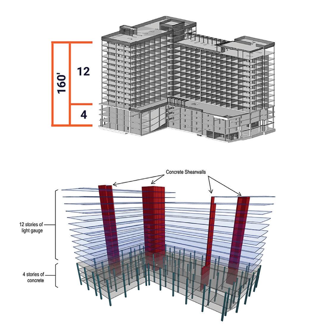

Over the past decade, with increasing demand for housing in the San Francisco Bay Area, Oakland has seen major growth and transformation of its skyline. The Lark residential tower is the most recent addition to Oakland’s Uptown district, offering its residents sweeping views of Lake Merritt, the East Bay hills, and the lively cityscape. Standing at 160 feet tall, the Lark is one of the first high rise buildings on the West Coast that combines panelized light-gauge load bearing walls with a curtain wall system facade.
Developer Holland Partner Group purchased the 38,000-square-foot site bound by Waverly Street, Harrison Street, and 24th Street with plans to build a multifamily apartment building. Holland then assembled a team, including Solomon Cordwell and Buenz (SCB) Architects and CKC Structural Engineers, to design the 16-story, 415,000-square-foot residential tower. The tower features 330 residential units, 13,000 square feet of double height ground floor retail with outdoor public plaza, four levels of above grade parking with space for
214 cars and 200 bicycles, fitness and leasing space, a fifth-floor outdoor terrace, and a 15th floor roof deck and sky lounge.
The project site is located in a high seismic region influenced by the San Andreas fault system. It has a highwater table and sits within a former tidal marsh area associated with the northwest arm of Lake Merritt. These site factors, combined with the building’s height, increased the lateral seismic forces. To mitigate the lateral forces and control escalating construction costs, CKC studied several building types and lateral systems from conventional concrete flat plate construction to structural steel and hybrid systems. CKC’s investigation led to the selection of a Type IB building where 12-stories of light-gauge floors are supported on four stories of concrete building with concrete shear walls extending from the foundations to the roof as shown in Figure 2. The

use of concrete shear walls throughout the height of the building helped eliminate the need for bracing and hold downs otherwise used in light-gauge framing. Concentrating the lateral force resisting system to the concrete shear wall elements simplified and streamlined the fabrication and erection of the light-gauge bearing walls. Additionally, a cantilever shoring system was used around the entire site that substituted the traditional soldier piles shoring system with tiebacks, eliminated the need to procure tieback easements, and assisted in managing the high-water table condition.
The light-gauge framing system consists of 3 ½ inches of lightweight concrete over a 2-inch deep dovetail composite metal deck with a total thickness of 5 ½-inches. The composite metal deck spans, without joists, up to 20 feet between panelized light-gauge bearing walls at the residential loading areas and up to 18 feet at the corridors and common areas. The deck is shored at center span until the concrete is hardened. The deck reinforcement is light and consists of welded wire mesh and mild reinforcement at the load bearing walls (Figure 3). This simplified floor system creates cost effective construction through the use of concrete on metal deck without joists, and concrete shear walls to carry the lateral loads. The floor slab deflections and vibrations were diminished by the continuous support of the panelized load bearing wall system and continuing the concrete over the wall support to create multi-span conditions which are less susceptible to deflections. The load bearing walls are comprised of metal studs and steel tube posts at lower levels where heavier point loads supporting concrete slab beams triggered the use of structural steel to reduce the stud density at wall ends as shown in Figure 3 and 4. A stud gauging/bundling strategy was also used to limit changing stud size and spacing as floor loads decreased over 12 stories from the transfer deck to the roof.
These panelized load bearings walls are prefabricated offsite, and then erected onsite to align perfectly with walls below. Stud bundling and gauge in bearing wall panels were reduced going up the building while maintaining the same 16-inch on center stud spacing. This allowed studs to stack vertically up the entire building which reduced the gauge of the load bearing walls' top and bottom tracks and enhanced stability. Door headers were eliminated by using the concrete deck spanning capacity. This approach helped streamline panel prefabrication where one stud length per level was used in all panels.
The load bearing walls were designed with specifications that provided the light-gauge subcontractor flexibility while still offering enough information to eliminate the need for deferred wall submittals. The 2-hour fire-resistance rating for the load bearing walls is provided with two layers of 5/8-inch Type X gypsum board on all four sides of the assembly. Corridor walls are all non-load bearing, which further reduced construction costs, improved constructability, and shortened floor cycle durations.
The four-story concrete podium sits on a mat slab foundation at grade and has columns terminating at the Level 5 concrete transfer deck. To improve constructability, the transfer deck was designed as a hybrid concrete slab with post-tensioned tendons supplementing the mild reinforcement, allowing the transfer deck to support its self-weight once stressed. This enabled shoring and re-shoring to be cleared immediately after stressing and eliminated the need for staged stressing to permit the curtain wall installation to start sooner.
The hybrid structural system allowed layout efficiencies at both parking and units. The columns in the podium structure were laid out to optimize parking and increase stall count per square foot without introducing transfer beams to shift columns at the residential floors (Figure 5). At residential levels, unit layouts could be optimized and standardized without having to work around columns. The resulting uninterrupted views at the Lark are a value add when combined with the quality of unit finishes expected for a high rise.


During the design phase, the state of California adopted the 2019 California Building Code that in turn referenced the ASCE 7-16 for seismic design criteria. The changes in seismic lateral loads from ASCE 7-10 to 7-16 were significant. The spectral acceleration for the Lark tower increased by as much as 45% between the two codes, as shown in Figure 6. To mitigate drift and resist lateral loads, a combination of three concrete cores and a blade wall were strategically located over the 25,000-square-foot, L-shaped floor plate as shown in Figure 2. The hybrid light-gauge steel system significantly reduced the building mass as compared to a traditional 8-inch concrete slab. The 5 1/2-inch light weight concrete on metal deck floor system is more than 40% lighter than the 8-inch concrete slab.
The lateral system was analyzed using a 3D Etabs model where the spectral response analysis method was performed. Due to the soil nature and the large earthquake overturning moments, CKC performed several parametric studies using soil springs to better represent the soil structure interactions. These studies were done through an iterative process and close collaboration with Rockridge, the geotechnical engineer. This work led to the use of a mat foundation supported on improved soil through a series of deep soil mixing (DSM) caissons as shown in Figure 7. This eliminated the need for deep pile foundations and lessened the reinforcement demands as well as removed waterproofing detailing at the deep pile penetrations into the pile caps. To reduce tonnage and congestion, the project took advantage of the ACI 318-14 code higher grade reinforcement Table 20.2.2.4a, where grade 80 steel was strategically used where applicable in foundations and shearwall boundary elements.
The Lark was designed with close integration of the hybrid structural system and other building systems to reduce costs and improve building efficiency. The system integration’s success was made possible with close communication between all members of the design and construction team. During early design, CKC, SCB, and Holland coordinated closely on units, standardizing layouts, and establishing efficient spacing for the

load bearing walls. Results included simplifying slab beams by moving units and keeping load bearing walls aligned across the corridor; strategic use of a single or series of 6-inch offsets between load bearing walls as needed to benefit unit layouts; and using a combination of HSS posts and slab beams to allow for wider openings at corner unit angled entry corridors. Unit layouts and load bearing walls were locked by the end of schematic design. Later, through coordination with Holland Construction, CKC further streamlined load bearing walls by cutting back portions of the walls to create wider pathways for transporting the unitized curtain wall panels throughout each floor during construction.
The project team decided to eliminate furred walls for MEPs occurring at load bearing walls for space and cost efficiencies. 30-inch plumbing riser openings were coordinated in the load bearing walls; these were further refined during BIM coordination and proved to be a success in construction. Putting electrical devices in the load bearing walls was more challenging due to severe congestion in lower-level walls with back-to-back or double back-to-back studs taking up approximately 50% of the linear length of each panel and clear spacing between studs ranging from 1 inch to 9 inches (Figure 8). The construction team overlaid the electrical layout on top of the prefabricated panel layout and coordinated moving studs inches to accommodate electrical where needed to meet client and accessibility needs.
Coordinating the unitized curtain wall attachment with the deck slab edge was another challenge solved through close communication. Talon, the curtain wall provider, was able to adjust its typical embed connection to work with the thinner deck profile. In addition,

the outermost portion of the slab edge was revised to have full-depth concrete, essentially creating a slab beam around the entire perimeter for the curtain wall attachment. And finally, the slab edge closure piece was coordinated during construction to avoid conflicts with the curtain wall embed (Figure 9).
The light-gauge system required a thorough understanding of the different types of structural elements to determine the appropriate fire-protection method. HSS posts integral to the light-gauge load bearing wall system are considered to be part of the wall assembly (i.e. light frame construction) per CBC 704.4.1. These elements have a high level of structural redundancy. Therefore, fire protection can be provided through the wall assembly membrane.
The construction team reduced the floor cycles by 2 days per pour by using double height HSS posts and double lift rebar cages at core wall boundary elements that were placed on alternating floors to maximize crane utilization. In addition, all plumbing penetrations were cored at a later stage which removed the plumbing sleeving activity away from the schedule critical path. The design and construction team created a well-thought-out shoring and reshoring plan to ensure deck levelness and flatness allowing prefabricated load bearing walls to stack and bear adequately.
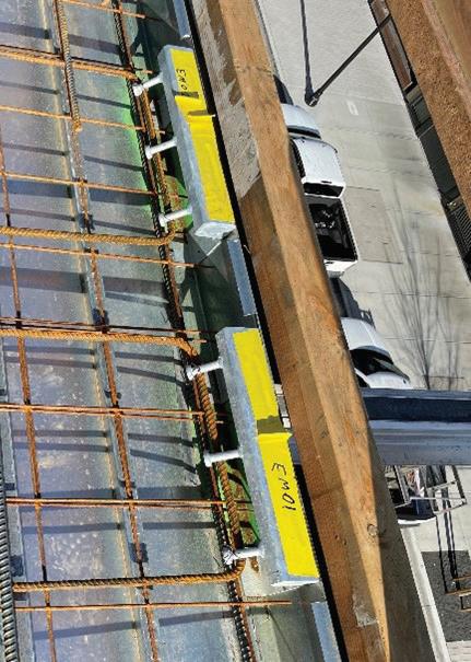

Early buildability meetings between CKC and Holland helped brainstorm ways to eliminate the need for an exterior perimeter scaffold system around the building. A glazed façade system was used instead of a punched opening exterior. This decision allowed Holland to take full advantage of the hybrid structural system, improved the construction schedule, and maintained a high-rise level quality of product with a lower cost.
The team worked closely from the early design phase to create a one-of-akind building that took hybrid light-gauge systems to new heights on the West Coast. This hybrid system was able to express the architectural design intent while maintaining the project budget and construction schedule. An added benefit is a reduced carbon footprint; the hybrid structure uses around 40% less cement on the residential floor slabs compared to traditional 8-inch concrete slabs due to the reduced floor thickness. While light-gauge steel construction has been around for years as an alternate non-combustible material to wood framing in low rise buildings, the Lark elevated light-gauge steel construction to reach 160 feet and made it possible to build towers with the combination of light-gauge load bearing walls and an exterior curtain wall system. This success story was made possible due to outside the box thinking by the project team and through elevated trust and collaboration. ■
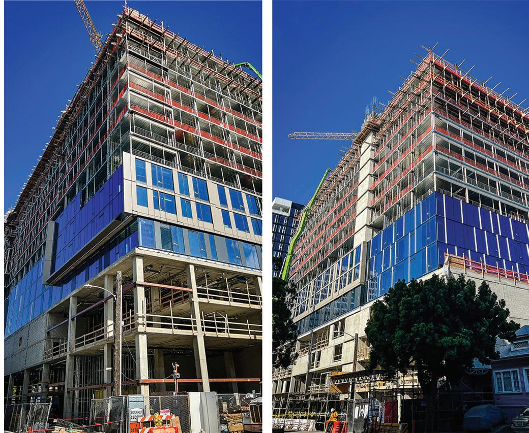
Joe Ferzli, PE, SE, is a Senior Principal at Cary Kopczynski & Company, Inc. P.S. (CKC). He is the Past President of the American Concrete Institute's Washington Chapter and a member of ACI Committee 374 on Performance-Based Seismic Design of Concrete Buildings, 318T Committee on post-tensioned concrete, and ASCE 7 seismic subcommittee.
Leslie Maienschein-Cline, RA, is an Architectural Project Manager at Holland Partner Group. She is a licensed architect with more than 12 years’ experience in design and construction of high-rise residential buildings.
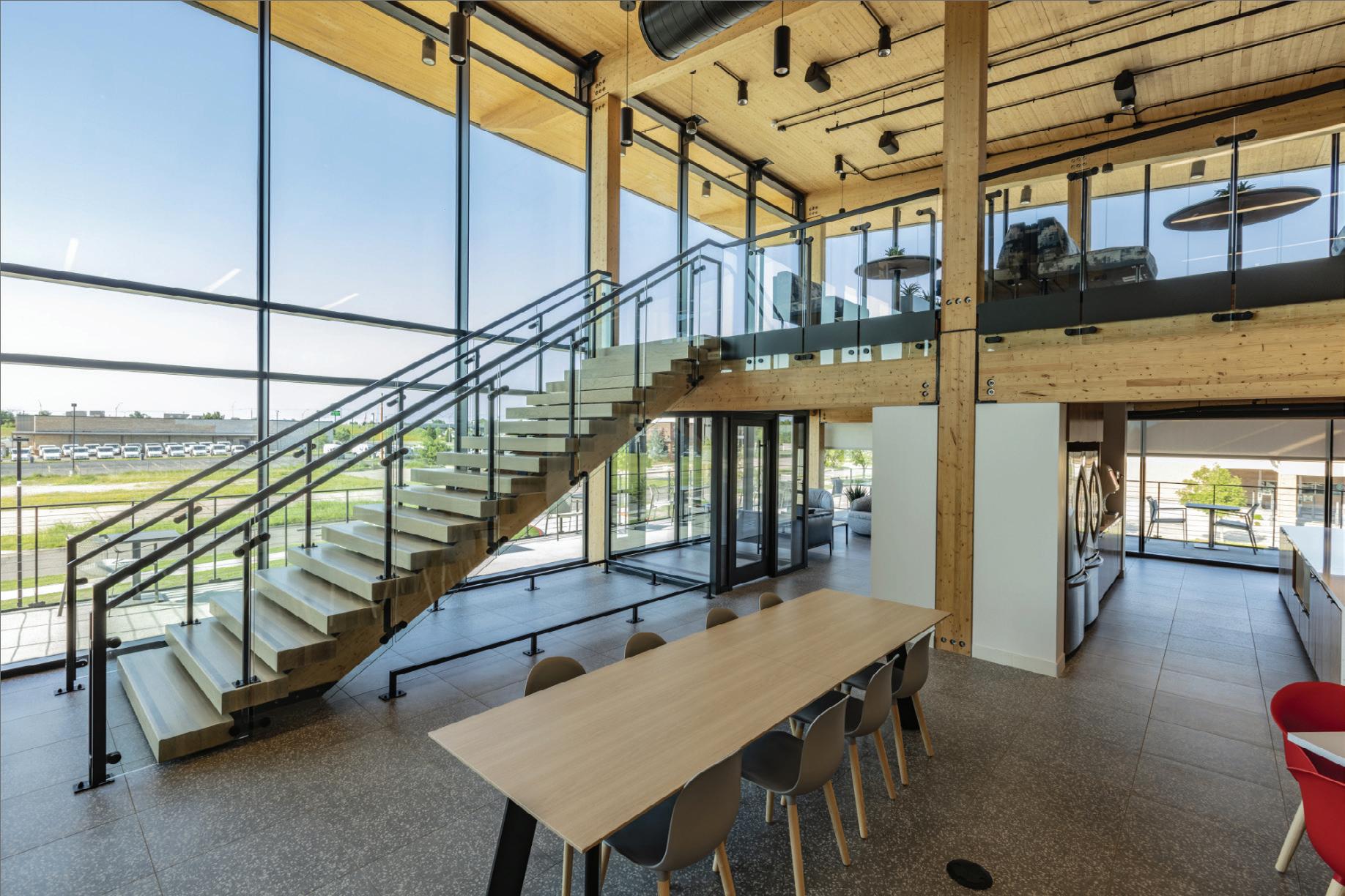
High-performance structural silicone glazing held to the steel frame of the three-story building provides durability and creates uninhibited sightlines.
By Chuck KnickerbockerThe First United Bank recently opened its doors to a stunning new building in Moore, Oklahoma.
Designed by Gensler, a global architecture firm, the building creates a welcoming space that supports the comfort and well-being of all occupants, all while being sustainable and timeless. These design goals help the building embody one of First United Bank’s key values of serving the community.
The 40,000-square-foot three-story building integrates innovative sustainable strategies, including rainwater harvesting, deep roof overhangs, efficient HVAC design and more. The design team extends the ecoconscious approach to its material palette, using a renewable mass timber structure and high-performance steel-framed curtain wall
system to create a simple yet contemporary cuboidal form.
Central to its intent, a steel-framed structural silicone glazing system (SSG) wraps around the bank’s facade, spanning the three floors and over 12,000 square feet. The highperformance structural silicone glazing is held to the steel frame by toggles, creating uninhibited sightlines to facilitate community engagement while providing durability to maintain its aesthetic appeal over time.
The Material Behind the SSG System
Structural engineers are familiar with the critical role framing materials play in
enabling expansive curtain wall facades. While glass occupies a larger surface area, it is the framing that supports the system. Among the commonly used materials, steel stands out for its exceptional stiffness, which is nearly three times greater than aluminum. (It has a Young's modulus of approximately 29 million pounds per square inch (psi) versus aluminum at 10 million psi). This inherent strength allows steel to carry heavier loads and resist deflections more effectively than aluminum.
For example, consider a curtain wall with a 5-foot mullion spacing subjected to a wind load of 30 pounds per square foot (psf). A typical aluminum mullion measuring 2.5 inches by 7.5 inches, including the glass and exterior cap, can span up to 12.5 feet but may experience a deflection of about 4.396 inches.
By replacing aluminum with steel, using 2.375-inch by 7.56-inch mullions under the same wind load and spacing, the deflection reduces to nearly 1.5 inches—about one-third of that of aluminum. This increased stiffness and load-bearing capacity enables project teams to extend the length of steel mullions, allowing spans of almost 16.33 feet—a 30% increase compared to their aluminum counterparts. In the case of the First United Bank, steel’s strength is what enabled the curtain wall to use sleek profiles that span greater lengths without requiring intermediate supports. The other contributing factor was advanced steel fabrication techniques first pioneered in Europe.
The expansive curtain wall at the First United Bank relies on a laser-welding method that utilizes long, flat carbon or stainless plates (generally 38 to 49 feet in length, and up to 1 ½-inches thick), which are first laser-cut out of flat plate products into bars or strips of the required size. These commonly include rectangles, channels, Ts, angles, square tubes, and I-beams. In particular, the bank employs 10mm (0.394 inch), 12mm (0.472 inch), and 20mm (0.787 inch) thick T-profiles.
Once cut, the edges of these precise sections are laser-welded to create composite shapes that eliminate the need for field assembly of any plates into desired shapes. This is because the profiles arrive on-site in their final forms, complete with the necessary machining for fitting horizontal and vertical sections. These pre-formed components are then assembled into curtain wall grids on-site by the glazing subcontractors. Consequently, the precise off-site manufacturing makes custom shapes that don’t fall into conventional categories also possible—including non-standard shapes for wall assemblies such as rectangles with inset walls or Ts with a round bar at the bottom of the web.
Additionally, when working with architecturally exposed structural steel (AESS), hot-rolled steel sections typically require grinding any exposed welds smooth and removing any visible markings. This is eliminated with modern fabrication because laser-welding produces profiles without exposed welds, mill roll marks, or identification marks. This advanced manufacturing method also allows for sharp corners (0.02 inches) in profiles, creating joints with no visible welding beads or fasteners. Another process allows for larger sections of thin-gauge carbon or stainless material, ranging from 24 gauge (0.0235 inches) to ¼-inches to be roll formed from steel coil stock into a variety of shapes. The rolling process allows for some complexity, such as gasket races and screw bosses (to name a few available features) to be formed into the completed shapes.

Extending a glass curtain wall from the ground to the roof on a threestory facade, without any intermediate support can be a significant challenge for any project’s engineering team. Transferring wind loads in a tall assembly without any floor plates or beams is a challenge that not every curtain wall material can address. Additionally, the glazing system’s primary framing member also needs to factor in aspects such as glass size, design loads, and connection or anchor points.
To achieve a curtain wall of the desired magnitude, the engineering team at the First United Bank project specified custom, heavy-duty, laser-welded “T”-shaped profiles as vertical mullions and rectangular framing profiles for the horizontal members, leveraging the advantages of modern steel fabrication techniques. The anchorage details were tailored specifically to the project environment, considering the project employed mass-timber structural systems. The result is steel-framed SSG curtain walls that span 12 feet, 23 feet, and 39 feet in height, with no intermediate vertical support points or splices in the main lobby at the First United Bank.
Two factors are at play that allow steel frames to not require splicing. First, the aforementioned strength and load-carrying capacity of steel enables single profiles to extend to such a height. Second, appropriately designed curtain wall systems with continuous steel-backed members can handle up to 38-foot spans without splicing. In fact, upcoming technology allows manufacturers to produce even longer lengths, but these profiles may be challenging to finish and ship to the site. That said, variables such as the center-to-center location of verticals, span length, and structural loads influence the size of the framing member required to support the project’s performance criteria (see sidebar). Still, when longer-length members are desired, it is possible to splice individual members together to form continuous framing members, enabling curtain walls of any height and length.
While evaluating mullion spacing and profile sizes is important for structural stability, detailing the connection point where the curtain wall anchors to the structure is equally important. Typically, in concrete buildings, a curtain wall’s frame is connected to the structure using embedded anchorage plates or devices, that allow welded or bolted connections of the anchor to the building frame. In steel buildings,

anchors can be welded or bolted directly to the building’s structure or to the face or edge of the floor.
However, because the First United Bank’s floor decking system is primarily cross-laminated timber (CLT), conventional anchorage details were not applicable. Instead, the curtain wall manufacturers worked closely with the structural engineering team to customize the connections between the anchorage, framing, and the building’s decking, something that is not far afield from conventional connections to steel or concrete structures. However, one of the goals for this meticulous detailing was to ensure that the connections were inconspicuous and did not interfere with the finished floor slabs.
Among these details, the anchor plates connecting steel frames to the building’s structural system were intentionally designed to be slightly larger to distribute the load evenly across the timber members, since the primary connection methodology between anchor and structure are wood screws, keeping in mind the capacity of the wood to hold the screws. Each anchor plate is secured with four or more screws, providing the necessary tie to the building’s structure for the curtain wall system. And while column or structure foreshortening (shrinkage) will generally not be included in the curtain wall specifications, this information is critical for the curtain wall designer to know how to properly design and specify anchorages, splice connections, and sealant perimeter joints.
The First United Bank’s project team utilized the advantages of steel’s material properties to enhance not only the system’s structural strength
Like any curtain wall, the maximum allowable height depends on factors such as applied loads and thermal expansion and contraction. The horizontal profiles also must address carrying the dead load weight of the glass for these glazing systems. These factors determine the size of the individual profiles, the number of splices (if required), and how the glass accommodates the movement within the curtain wall system at splice locations. Consider a load calculation for a six-story curtain wall that is intended to be anchored at each floor to the building, at a nominal 12-foot 6 inch to 15-foot floor-to-floor height. Rather than forcing the curtain wall’s full weight (approximately 25 psf due to thick glass) on the lowest level of the structure, structural engineers can design the system to carry the imposed curtain wall dead load on each floor or at intermittent floors. Each anchor will typically also impose a lateral load (due to wind) into the building’s structure. To accommodate the load, the steel mullion may be sized at 2.3-inch x 7.1-inch x 0.1-inch thick and require a 1/2-inch dynamic splice joint between two floors carrying the dead load. Additionally, to ensure the live load deflection does not exceed 0.375 inch under these conditions, adjustments may be necessary to limit the sizing of the structural steel frame. Exact conditions often vary from project to project, allowing larger splice joints and/or greater structure flexibility. It is important to communicate these requirements in the construction documents for review by the steel system detailers.
but also the user experience. “Establishing a connection to the outside and maximizing natural light are two traits proven to promote the well-being of building occupants,” Jorge De Loera, one of the architects on the project, reports. Building on this evidence-based approach, the team at Gensler integrated biophilic design, which connects occupants to the natural world, by opening the interiors of the First United Bank to uninterrupted views of the landscape outside.
To achieve this goal, slender steel profiles empowered Gensler to facilitate larger opening sizes without the need for additional support. This in turn increased the surface area for light penetration, filling the interiors with natural light and offering sweeping views of the Oklahoma prairies and skies. The narrowness and shallowness of the metal profiles further reduced interruptions to sightlines and created a more monolithic facade. Detailing it further, the project team enabled an uninterrupted, frame-free facade from the outside by specifying a structural silicone glazing (SSG) curtain wall system.
In SSG systems, structural silicone attaches compatible lites to modular carrier frames or cassettes. These carrier frames are then pressure-glazed via the use of toggles against continuous gasketing mounted on the steel framing. The gasketing is the primary means to resist air and water penetration to the building interior while keeping the water off the face of the steel, eliminating the need for
exterior pressure plates and caps typical in curtain wall design. The SSG system enables a high-performing building envelope at the First United project, while still utilizing steel’s strength.
Another critical factor is the amount of sealant required to hold the glass to the frame; this is called the bond line width. Its dimension is determined by the size of the glass lite and the anticipated design wind load. In addition to the amount of gasket or glazing tape and the exterior weather joint between lites of glass, the bond line width generally sets the width of the framing member.
Beyond the user experience, sustainability and energy efficiency were key considerations for the First United Bank. The design teams naturally opted for high-performance insulated glass units (IGU) to accompany the steel framing. The four different high-performance curtain wall configurations in the project have glass thicknesses ranging from 1-inch to 1-1/8-inch and weigh between 5.8 and 9.4 psf. While traditional framing may have required larger profiles to support additional weights, steel’s inherent strength allows it to improve energy efficiency using smaller sections.
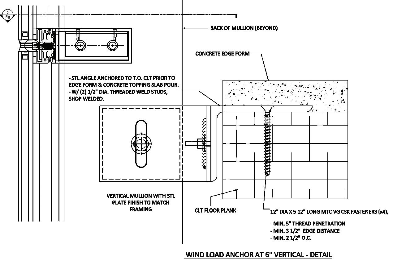

Additionally, steel has a thermal conductivity (31 British thermal units per hour [BTU/H]) nearly 74 percent less than its aluminum cousin (118 BTU/H). This is equivalent to that of thermally broken aluminum frames. Moreover, some advanced steel frames do not need a traditional thermal break due to their profile designs. Likewise, the system at the First United Bank optimizes steel’s ability to support highperformance glazing and “minimize thermal breaks,” adds De Loera, augmenting the bank’s larger sustainability goals.
The sleek steel-framing profiles at the First United Bank enable longer spans, allowing the SSG curtain wall to blur spatial boundaries and transform the way visitors and staff interact. “People in the lobby can see the people in the café, all the way to the mezzanine, making these common spaces feel full of energy,” De Loera explains. By establishing visual connectivity through the high-performance glazing system and spatial planning, steel frames facilitate an interconnected, communal environment, enabling engagement and interaction.
Steel’s material capabilities and strength support the engineering teams at the First United project to deliver a high-performance glazing system that shapes the bank's values of promoting community engagement and sustainability. While doing so, it also helps them materialize the design team’s pursuit to “create monumental spaces,” positioning the bank’s building as a market differentiator for years to come. ■
Chuck Knickerbocker is the curtain wall manager for Technical Glass Products (TGP), a supplier of fire-rated glass and framing systems, along with specialty architectural glazing products. With over 40 years of curtain wall experience, Chuck has successfully worked with numerous architects, building owners, and subcontractors from development of schematic design through installation.
A new tower isn’t just transforming downtown Austin’s skyline—it’s reshaping the future of high-rise wind design.
By Sean P. Clifton, PE, SE, and Kevin P. Aswegan, PE, SEThe University of Texas at Austin often touts the phrase, “What Starts Here Changes the World.” That is precisely what is happening with ATX Tower—the world’s first high-rise tower to incorporate the American Society of Civil Engineers (ASCE) Prestandard for Performance-Based Wind Design (PBWD)—under construction in Austin, Texas. PBWD will likely revolutionize how tall buildings are designed for wind loads, creating more reliable, lowercarbon, and less costly buildings.
Rising 58 stories and 671 feet above downtown, ATX Tower is located at 321 West 6th Street. It will offer 561,000 square feet of office and residential space for tenants and residents of the city’s historic entertainment district. The project is expected to top out this summer and be completed in 2025. Innovation doesn’t happen overnight. Magnusson Klemencic Associates (MKA) has been developing PBWD for much of the past decade through funding research at universities nationwide, participating in professional committees, and testing designs through numerous case studies of actual buildings. Since the ASCE Prestandard for PBWD’s release in 2019 (see sidebar below, “ASCE Prestandard for PBWD Primer”), MKA searched for the right project on which to implement PBWD, and the stars finally aligned on ATX Tower with a supportive ownership partnership of Tishman Speyer Properties and Ryan Companies and a collaborative architectural team of Handel and Page Southerland Page.

Before incorporating PBWD into the project’s design, MKA and project wind engineer CPP Wind Engineering Consultants (CPP) had to convince the ownership team and the City of Austin’s Development Services Department, which is in charge of building permitting, that there was value in applying this first-in-the-world approach.
Wind tunnel testing began in May 2021 under the guidance of CPP Senior Principal Roy Denoon, whose team conducted multiple test regimens to evaluate wind loads on the structure, cladding, and pedestrian environment for ATX Tower. A 1:350 scale physical model was used to consider the tower’s geometry and the impact of adjacent buildings by testing wind influences from 36 different directions to identify the controlling combinations of wind speed and building response.
From these early test results, MKA and CPP discovered several key factors that made ATX Tower a good candidate for the new methodology:

• Shape—The tower’s slender, square shape produced a significant dynamic response caused by wind vortex shedding.
• Location—The surrounding towers proved to buffet ATX Tower as wind was redirected.
• Test Results—Wind loads predicted by wind tunnel testing revealed loads 20-30% higher than building code estimates—particularly from the east and northeast directions.
The tower’s design needed to accommodate the increased wind demands, and MKA felt PBWD could be an excellent alternative to increasing the sizes of structural members. The firm tapped into its extensive experience in developing Performance-Based Seismic Design (PBSD) to investigate the feasibility of implementing a PBWD methodology to mitigate the impacts of higher-than-expected wind demands. Stakeholders agreed, proving to be open-minded and supportive of PBWD.
With the stakeholders’ preliminary approvals in place, a peer review team made up of wind engineers and practic ing structural engineers was assembled to collaborate and review the design. The design process involved three key steps:
• The team needed to verify the resi dents would be comfortable during common wind events. CPP confir med that predictions of occupant comfort were within industry-stan dard acceleration limits without any modifications to the building massing or structural layout.
• A more detailed methodology, as out lined in the ASCE Prestandard, was then employed to assess story drift. Typically, story drift is calculated as the difference in displacements
between adjacent levels. For ATX Tower, a more detailed assessment of racking drift specific to the exterior walls and internal partitions was pursued. MKA compared these estimates to recommended limits for exterior glazing, interior drywall partitions, and masonry. Movements proved to be within acceptable limits for the various non-structural materials.
• Finally, MKA’s team designed and verified the strength performance, which proved complex and challenging. The stated performance objective for the main wind force-resisting system—“Continuous Occupancy, Limited Interruption”—allows specific structural system elements to respond inelastically. In ATX Tower, these elements were limited to the shear wall coupling beams, shear wall flexural response, and outrigger column tension action. Following the ASCE Prestandard provisions, these elements were designed to a 1.25 demand-to-capacity ratio, using expected material strength and phi factors of 1.0.
With the design completed, MKA’s team analyzed and verified the performance by developing a detailed analysis model using non-linear properties where elements may experience inelastic behavior. Engineers calibrated those properties to physical testing completed at several universities. The analysis model was then subjected to a time history loading protocol involving five unique windstorms. Each one-hour storm represented wind from a different direction that controlled an aspect of the design.
The analysis model ultimately took an impressive one month of runtime to complete the simulation of all five storms. This runtime was significantly more than the typical PBSD analysis due to earthquakes being short-duration events compared to windstorms. However, when engineers reviewed the terabytes of output data, the building exhibited excellent performance. The results showed limited yielding in a small number of coupling beams and little yielding in the shear walls or outrigger columns. This result was exactly what the team was looking for, demonstrating that acceptable performance can be achieved with more rigorous engineering using PBWD.
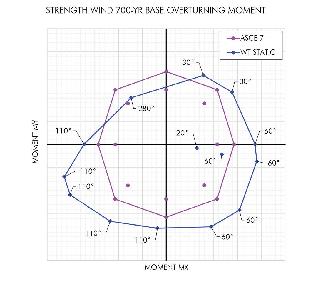
As ATX Tower was the first highrise to utilize the PBWD process, the team also completed a parallel codeprescriptive design as a “fallback” in case of trouble securing the permit. The PBWD design was approved and permitted, but the parallel design proved valuable. The prescriptive design
 Photo credit: Handel
allowed the project team to compare the savings in quantities and materials between the novel PBWD design and a code-prescriptive design. The PBWD design offered many project benefits:
• 350 tons of reinforcing steel, 125 tons of structural steel, and 1,800 cubic yards of concrete were saved.
• A 5% reduction in the structure’s total cost was realized.
• Floor plans were improved because shear wall thickness was reduced.
• The construction schedule was improved through the reductions in materials.
• A 6% reduction in embodied carbon was achieved.
Remarkably, the PBWD process didn’t slow the project’s aggressive schedule. The structural permitting process was rapid and smooth as the city officials participated throughout the design process, rather than simply reviewing after the design was complete. The first drilled shaft was installed a mere 12 months from the start of Schematic Design. This efficiency was achieved thanks to a collaborative approach among the design team, client, general contractor, and city officials.
PBWD has sparked an industry that historically struggles to innovate and improve upon many years of status quo. Akin to PBSD, which has become the standard of care when designing high-rise buildings in America’s earthquake-prone regions, PBWD could become the norm for designing tall buildings in regions vulnerable to fierce wind events.
Successfully incorporating PBWD into the ATX Tower’s design has spurred MKA to implement this approach in other Austin projects, though a sluggish real estate market has paused that activity. Elsewhere, PBWD research and advancements are ongoing at universities worldwide, and the American Concrete Institute is finalizing guidelines to implement PBWD for concrete members. When it comes to PBWD’s future, the wind is at the industry’s back. ■
Sean P. Clifton, PE, SE, is a Senior Principal at Magnusson Klemencic Associates (MKA).
Kevin P. Aswegan, PE, SE, is a Principal at MKA.
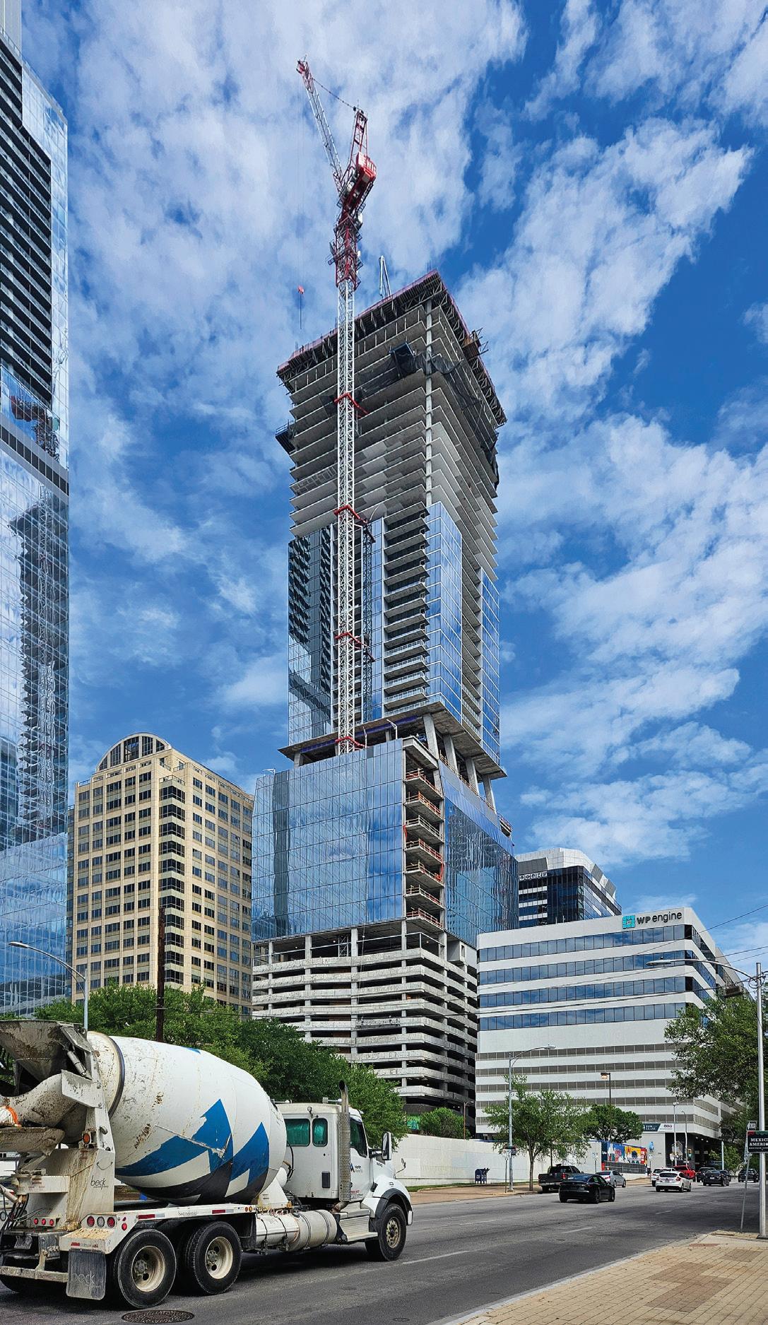
First released in July 2019 and later updated with v1.1 in 2023, the ASCE Prestandard for Performance-Based Wind Design aims to establish an approach and guidelines for implementing PBWD for buildings. The Prestandard was developed through a collaboration between practitioners, researchers, and building officials to outline an approach to enhance the process by which buildings are designed for wind forces. This approach was primarily based on the 25 years of development and implementation of Performance-Based Seismic Design (PBSD) worldwide and a recognition that buildings controlled by wind could also benefit from a similar approach.
The Prestandard outlines an approach to rigorously investigate serviceability and strength performance using the latest materials testing and research combined with the advanced analytical capabilities of modern computing. The result offers a realistic picture of the building’s behavior subjected to wind by applying actual dynamic wind loads vs. prescribed static loads. It allows for a more efficient structure, reducing structural materials.


Composite joists save up to 35% weight versus wide-flange floor systems
Smart engineering reduces material costs and improves performance. New Millennium flush-frame connections feature a more efficient design that eliminates beam torsion concerns. Our published set of standard flush-frame connections simplify design and specification. Now, structural engineers can quickly and accurately specify flush-frame connections, streamlining fabrication and erection. Together, let’s build it better.
connection designed for efficiency
Standardized connections reduce design time Joist reaction point occurs at beam centerline
More than 50 years after inventing a structural system that revolutionized skyscraper design, SOM engineers are improving and adapting it for a changed construction industry.
By Aaron Mazeika, PE, SEIn 1968, as construction workers hoisted steel beams more than 1,100 feet above Chicago’s lakeshore, the John Hancock Center reached its full height—an achievement that would forever change not only Chicago’s skyline, but the entire field of tall building design and engineering. Hancock’s “braced tube” structural system, devised by SOM engineer Fazlur Khan together with architect Bruce Graham, introduced a new era of efficient skyscraper design. However, the foundations of that design innovation were laid even earlier, and today, more than 50 years later, designers at SOM are continuing to improve upon the system.
The evolution of the braced tube structural system began with the initial conception of the Tube Frame structural system implemented by Khan at the Chestnut-Dewitt apartment building in Chicago (completed in 1966). Up until that point, rigid frame structures had typically been

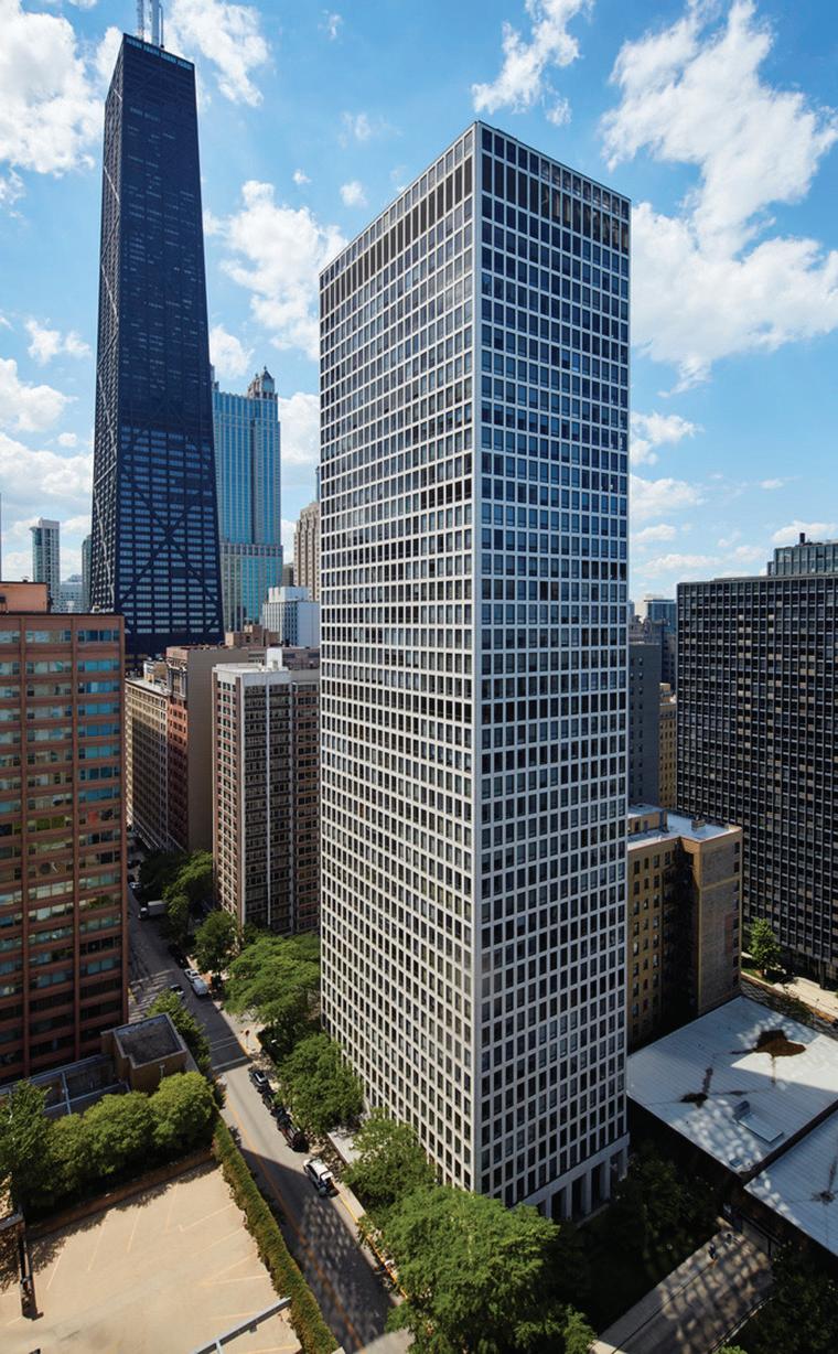
conceived as an array of two-dimensional frames passing through the building in two orthogonal plan directions, and along each column line. The stiffness of the frames was limited by practical considerations—how closely columns could be spaced without compromising the functionality of the interior space. By using closely-spaced columns around the building perimeter, Khan discovered that the structure could perform like a thin-walled tube cantilevering from the ground; densifying the columns at the perimeter could be accommodated without impacting the building function, while enhancing the stiffness of the perimeter tube. This could allow the interior columns to resist only gravity loads, and therefore be spaced further apart, resulting in more functional and flexible interior spaces. In part, this structural innovation was achieved by conceiving of the structure as functioning three-dimensionally, with the tube acting as a 3D box section rather than an array of 2D frames.
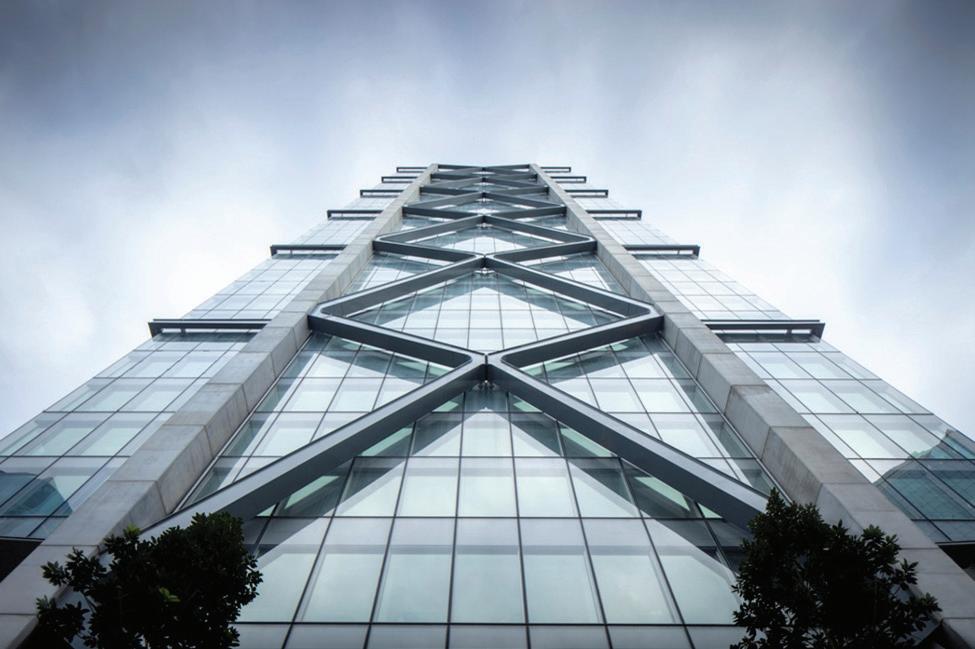
Designed at the advent of computer-based structural engineering analysis, this behavior was confirmed by performing more complex analyses than previously possible through hand calculations.
With the development of the braced tube system for the John Hancock Center in Chicago (now known as 875 North Michigan Avenue), Khan rationalized that an even more efficient structural system for a tall building could be achieved by replacing the perimeter frame tube (as used at Chestnut-Dewitt) with a diagonalized steel braced truss on the perimeter faces of the building. Whereas the frame-tube resisted lateral deformations through flexural and shear strains in the spandrels and perimeter columns, the braced tube resisted lateral building deformations through axial strains in the truss members. In the same way that a diagonalized truss is more efficient than a Vierendeel truss in spanning and bridging applications, the use of a diagonalized truss on the perimeter of the John Hancock Center established a new benchmark for the minimum structural material usage for a tower of this height. While the innovation of employing a braced tube for the lateral system of the John Hancock Center resulted in a step change in design efficiency, the precise geometry of the bracing employed was not the most efficient possible, as subsequent research into optimal truss geometries has demonstrated.
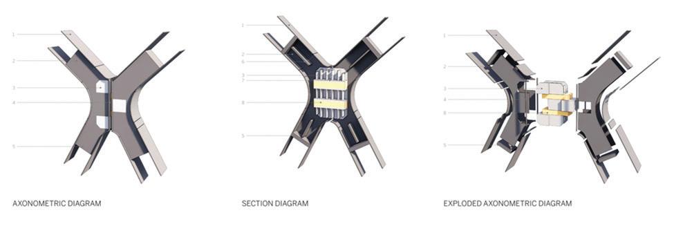
Starting around 2008—approximately 40 years after the design and construction of the John Hancock Center—SOM partner and structural engineer William F. Baker led a research team within SOM to explore optimal truss geometries. Building on studies on continuum optimum frames by Michell and discrete optimum trusses by Prager, the team applied this knowledge to increase the efficiency of SOM’s tall building designs. One finding was that the X-brace configuration of the John Hancock Center facade geometry could be improved by moving the central intersection node upwards, at the three-quarters height of the braced bay. This would be the optimal point when stiffness controlled the design, and buckling of the individual compression members was not a factor. This optimal point could be lower if compression buckling of the individual members became a controlling factor. This simple adjustment to the geometry of the braced bay offers an approximate 10 percent increase in the material efficiency of the brace. It is interesting to think that the iconic X-brace geometry of the John Hancock Center would likely have been different had the design team had knowledge of discrete optimal truss geometries at that time.
Following the research team’s findings, SOM’s design and engineering team quickly found opportunities to implement new knowledge about optimal truss geometries in the firm’s active design work. The first constructed example was at 100 Mount Street, a 35-story office tower in North Sydney, Australia, completed in 2019. This reinforced concrete linear bar building is designed to maximize daylight and open space for tenants, with a high-performance closed cavity facade and the core offset to one end of the floorplate. To prevent a torsional response to lateral wind and seismic loading, a stiff, lateral force-resisting element was required at the opposite end of the building, where a primarily transparent facade was required. The optimal discrete truss geometries developed by SOM’s research team provided the most effective and material efficient solution.
While our knowledge of optimal truss geometries has advanced significantly, changes in the construction industry have presented new barriers to the implementation of trussed tube buildings. Most notable is the transition from steel to reinforced concrete as the preferred construction material for tall building structures. When the John Hancock Center was built, all-steel construction was the method of choice for very tall building structures, but in the 1980s, as high-strength concrete technology
improved, the economics of tall building construction shifted to using reinforced concrete where possible. The shift from all-steel is significant, because even though steel is ideal for the brace elements due to its isotropic characteristic (meaning they can be subjected to both tension and compression forces in equal magnitude), steel braces are difficult to incorporate into a reinforced concrete building due to an incompatibility between the long- term behavior of steel and concrete. Concrete columns tend to shorten over time when subjected to sustained gravity load, due to a phenomenon called creep, whereas the creep in the steel braces is insignificant in comparison. Typically, the braces’ configuration allows them to act as an alternate gravity load path to the columns. As the concrete columns creep, gravity loads gradually transfer from the columns to the braces, increasing the forces in the braces over time and requiring them to be larger, and therefore much less materially efficient. For 100 Mount Street, SOM’s design and engineering team solved this problem by incorporating a special sliding detail at the central node of the brace. The design goal was to isolate the lateral and gravity load paths. If all the gravity load could be kept within the reinforced concrete columns, then the braces would experience only equal and opposite forces due to lateral wind and seismic loads. The bracing system would then be a symmetrical system subject to perfectly antisymmetric loading. This condition simplifies the load transfer at the central node such that only vertical loads need to be transferred from one side of the central node to the other. A sliding detail consisting of a series of interlocking horizontal plates enables this load transfer, but also allows a “release” that isolates the bracing system from gravity loads. When the columns shorten due to creep, the two halves of the central node simply slide slightly towards each other, allowing the columns to shorten without load being transferred to the braces. In a similar way, thermal strains in the braces can be released without inducing axial loads in the bracing. While the sliding detail at 100 Mount Street was successful and continues to perform as designed, it was complex to fabricate and labor-intensive to install. The design team soon found an opportunity to improve this concept in the design of another high-rise building, 800 Fulton Market, completed in Chicago in 2021. This project is at the edge of the Fulton Market Historic District with protected views to the south and southwest due to the low scale of those historic buildings. With a large- scale office building immediately to the north of the site, the preferred architectural massing was a rectangular long-span bar building with a narrow, offset core on the north side of the site. Early contractor price feedback favored post-tensioned concrete beams over a steel gravity frame, and preliminary analysis suggested supplemental lateral stiffness was required over that provided by the slender core. This series of conditions lead to a design solution similar to 100 Mount Street, with reinforced concrete gravity frame and a steel braced lateral force resisting system, and therefore an opportunity to improve on the design of the brace nodes.
At 800 Fulton Market, the team discovered that all the performance objectives of the central node could be achieved by replacing the complex sliding mechanism with a much simpler geometric mechanism:
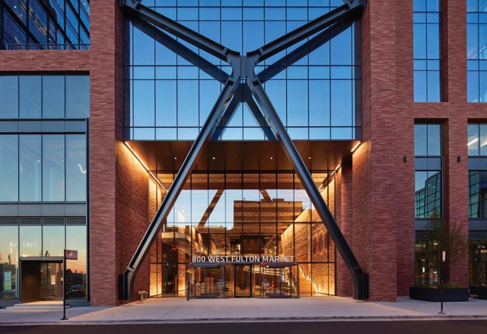

simply displacing the central node of the braced bay 24 inches out of the plane defined by the four corners of the braced bay. The four diagonal brace members in each bay form the edges of a shallow, horizontal pyramid. When the reinforced concrete columns eventually shorten due to creep, the central node simply moves further out of plane, forming a slightly ‘taller’ pyramid. Similarly, when subjected to temperature variations, the braces lengthen and shorten and the central node automatically moves inwards or outwards to reconfigure the geometry without inducing any forces in the bracing. In this way, the forces acting on the braces are limited to wind, which are equal and opposite axial forces, thereby stabilizing the geometry of the central node. When one diagonal is in compression and tends to buckle outwards, the other diagonal is automatically in tension, holding the central node in position. The detailing of all the connections in the brace system allows this geometric reconfiguration with only elastic deformations of the steel plates. Instead of a pin-jointed hinging mechanism, a high-ductility “hinging plate” is used at areas of maximum deformation demand. The hinge is formed by a simple rectangular steel plate with the stiffness of the hinge designed by optimizing the height, length, and thickness of the plate. The design challenge of the hinge is to minimize its flexural stiffness to reduce stresses induced as the brace geometry reconfigures, while maintaining adequate strength to transfer the required shear between the two halves of the node. The plate also is designed to withstand the expected deformations elastically and at stress levels and cycle counts that mitigate any concerns about fatigue in the plate itself. To alleviate concerns about fatigue in the welds connecting the hinging plate to the remaining parts of the steel node, the hinging plates are machined down to a dog-bone profile from a thicker plate, significantly reducing the stress levels at the welding points. Beyond the hinging plate, the geometry of the nodes is all determined by analytical optimization. A deliberately oversized design space is analyzed and the material in areas of low stress is removed, until only the useful material remains. The sculptural nature of the nodes is an honest expression of the force flow through the nodes.
SOM has a long history of designing buildings through an integrated approach, producing engineering solutions that are expressed in the building architecture. These buildings’ designs enable an inherent understanding of how they work, and they tend to be well received by the general public. 800 Fulton Market is a prime example, with its state-of-the-art integrated design and research-driven structural systems that are carefully detailed to optimize performance and artfully expressed in the architecture.■
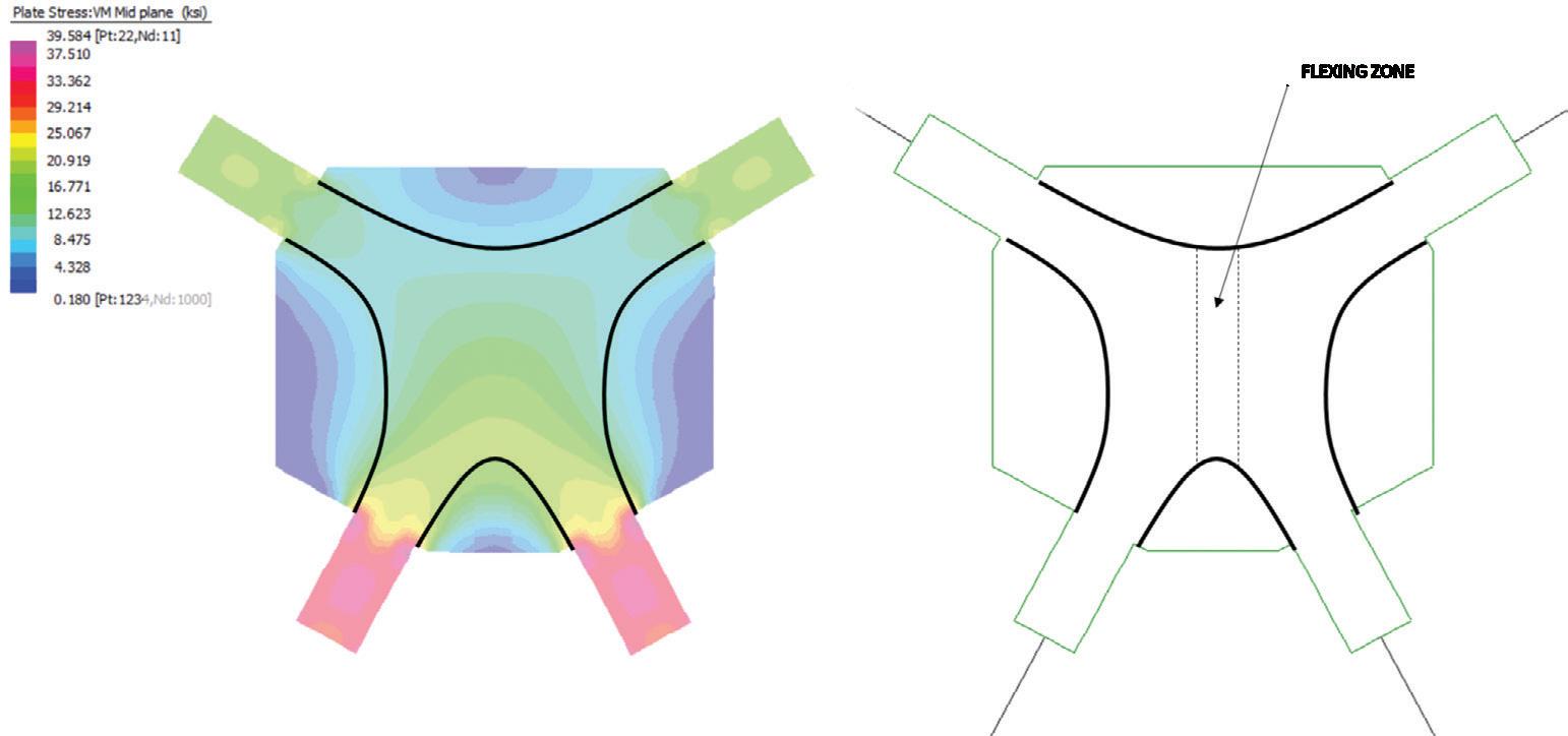
Aaron Mazeika is a Structural Engineering Principal with SOM. Licensed both as Structural Engineer and Architect, Mazeika focuses on an integrated approach to design that seeks to infuse SOM's architecture with innovative and efficient structural systems.
The 2024 ANSI/AWC Fire Design Specification for Wood Construction is an updated guide containing calculations-based means of demonstrating code compliance.
By Jason Smart, PE, Bradford Douglas, PE, and John “Buddy” Showalter, PEThe 2024 edition of the ANSI/AWC Fire Design Specification (FDS) for Wood Construction provides a new design resource where fire design of wood members, assemblies, and their connections is required by applicable building codes. The 2024 FDS (Figure 1) was approved as an American National Standard in September 2023 and applies to fire design of wood construction covered under the 2024 ANSI/AWC National Design Specification (NDS) for Wood Construction.
Since 2001, fire design provisions in Chapter 16 of the NDS have provided designers with a calculation-based means of demonstrating compliance with code-required structural fire-resistance ratings for exposed wood members. More recently, additional calculation procedures have been developed to address the added fire resistance and thermal benefits of protection using additional wood cover, gypsum panel products, and some types of insulation. Shortly after the release of the 2021 FDS pre-standard, AWC’s consensus committee formed a new task committee to review the pre-standard. This consensus development process culminated in the first version of the FDS being approved as an ANSI American National Standard in September 2022. In the 2024 FDS, these calculation procedures for fire design of protected wood members have been combined with design provisions consistent with those of the 2024 NDS Chapter 16 for design of exposed wood members.
In developing the provisions of the FDS, the most reliable data available from laboratory tests and experience with structures in service have been carefully analyzed and evaluated for the purpose of providing, in convenient form, a national standard of practice. But before delving into the contents of this new design resource and how it can be used in the fire design of wood construction, a brief review is in order for how fire safety has historically been addressed in wood construction and how modern code provisions related to fire safety were developed.
Long before any models were developed to quantify char depth in wood as a function of fire exposure time, the

general fire performance behavior of wood was recognized in traditional heavy timber construction, which was sometimes referred to as mill construction.
In traditional heavy timber construction, the exterior walls are constructed of noncombustible materials and the interior structural elements are large-cross-section wood members with sufficient size to afford acceptable performance during a fire. Such interior structural elements, including floor assemblies and interior partitions, were typically constructed without concealed spaces, which could otherwise obscure a fire in its incipient stages and conduct it to other portions of the building. Traditional heavy timber construction is still recognized in U.S. model building codes, under its current designation as Type IV-HT construction in the International Building Code (IBC) and Type IV in the NFPA 5000 Building Construction Safety Code .

Most of the building elements in IBC Type IV-HT and NFPA 5000 Type IV construction are not required to have specified minimum fire-resistance ratings because they are recognized as having some qualitative level of inherent fire resistance owing to their large cross-sectional size. But for other construction types, building codes typically require specific building elements to meet minimum fire-resistance ratings. These fire-resistance ratings can be established either through standardized testing, calculation, or a number of other code-recognized methods. While charring of the wood causes section loss of an exposed wood member, it has been long understood that the layer of char which develops on the wood surface provides the tradeoff benefit of a certain degree of thermal protection to the remaining uncharred section beneath the char layer. This protective char layer thickens as the char front penetrates deeper into the wood member, thereby providing an increasing amount of insulation to the uncharred wood below and slowing the rate of char progression through the cross-section of the member. The resulting nonlinear rate of char progression through the wood member as a function of fire exposure time can be accurately modeled as a means of predicting performance under specified fire exposure conditions – a fact that is explicitly included in calculation procedures recognized in U.S. model building codes.

The main body of the FDS contains three chapters, plus additional design information provided in supplements. As with most design standards, Chapter 1 provides the necessary scoping information, notation and definitions to terminology used in the standard, referenced material standards and general fire design requirements. Chapter 2 specifies ignition and flammability requirements for wood products and provides referenced test standards to be used to show compliance with these requirements. Chapter 3 establishes fire-resistance design provisions that apply to all wood structural members, assemblies, and connections designed using the NDS. The supplements, which are referenced in the FDS, provide information on tested flame-spread performance of woodbased interior finish materials and fire-resistance ratings of tested wall and floor/ceiling assemblies.
Among the general fire design requirements in Chapter 1 are provisions governing minimum cross-sectional dimensions of heavy timber members. These minimum dimensions are consolidated into three tables, plus an additional table providing requirements for toppings on heavy timber floor decks. Chapter 1 also lays out the general design requirements for fire-resistance-rated wood members and assemblies. Specifically,
Section 1.7 addresses the critical design concepts of maintaining continuity of fire-resistance ratings between adjacent rated assemblies, and ensuring minimum required fire resistance of construction that supports gravity loads from a fireresistance-rated building element or assembly.
Also in Section 1.7 are general provisions requiring protection of connections between wood members or assemblies that are required to have a fire-resistance rating. This protection must be designed in accordance with FDS Section 3.10 to protect and insulate every part of the connection for the full required fire-resistance-rating time.
Portions of Section 1.7 that were revised in the 2024 FDS are the newly enhanced provisions for detailing at joints and intersections between fire-resistance-rated wood assemblies. The FDS Commentary on these provisions includes diagrams, such as the example in Figure 2, to illustrate how intersections between fire-resistance-rated assemblies can be detailed to prevent premature burn-through.
The ignition and flammability requirements of Chapter 2 have been coordinated with requirements of model building codes but have been expanded to more thoroughly address requirements specific to wood materials and assemblies. Section 2.2 clarifies requirements for ignition-resistance of wood products used on exterior surfaces. While wood products are exempt from

A timeline of developments culminating in the fire design provisions of the 2024 FDS is depicted here. More details of those milestones are listed with the online article at www.structuremag.com.
the code requirement to perform testing in accordance with NFPA 268, Standard Test Method for Determining Ignitability of Exterior Wall Assemblies Using a Radiant Heat Energy Source , because ignition of wood usually occurs at or above the heat flux limit of 12.5 kW/m 2, reference to the model code requirements is provided.

Flame spread performance requirements of wood products used as interior finish materials are addressed in Section 2.3. This is where material classifications are provided based on flame-spread index and smoke-developed index, as determined through testing in accordance with ASTM E84. Reference is made to FDS Supplement A, in which flame spread indices and smoke-developed indices are reported for various wood and wood-based materials. Also in Section 2.3 are provisions addressing qualification of fire-retardant-treated wood (FRTW) and wood-based products with fire-retardant coatings. For both product types, the effects of the fire-retardant treatment or fire-retardant coating on strength and stiffness are required to be evaluated in the approval process and accounted for in design.
Section 2.4 contains provisions addressing vertical and lateral flame propagation on exterior wall coverings and building projections. In addition to ignition resistance and flame spread requirements, combustible exterior wall coverings and building projections have limitations based on coverage area, coverage height and fire separation distance. Under certain conditions, testing of exterior wall covering assemblies in accordance with NFPA
285, Standard Fire Test Method for Evaluation of Fire Propagation Characteristics of Exterior Wall Assemblies Containing Combustible Components, is required. Minimum performance requirements for firestopping, fireblocking, and draftstopping are provided in Section 2.5, along with a list of materials that are prescriptively recognized for use as fireblocking and draftstopping. The FDS Commentary provides technical justification and values to quantify the relevant parameter of fire performance (i.e., burnthrough time) for each prescriptively recognized fireblocking material listed in this section.
The scope of 2024 FDS Chapter 3 is aligned with that of 2024 NDS Chapter 16, in that it contains design provisions for determining the fire resistance of any wood construction that is covered under the scope of the NDS. Section 3.1 sets general requirements for establishing fire-resistance ratings. This includes defining the standard exposure under which fire-resistance ratings are to be established and loading requirements for both allowable stress design and load and resistance factor design of loadbearing fire-resistance-rated assemblies. Section 3.8 complements the provisions of Section 3.1 by referencing FDS Supplement B, which provides listings and descriptions of tested 1- and 2-hour
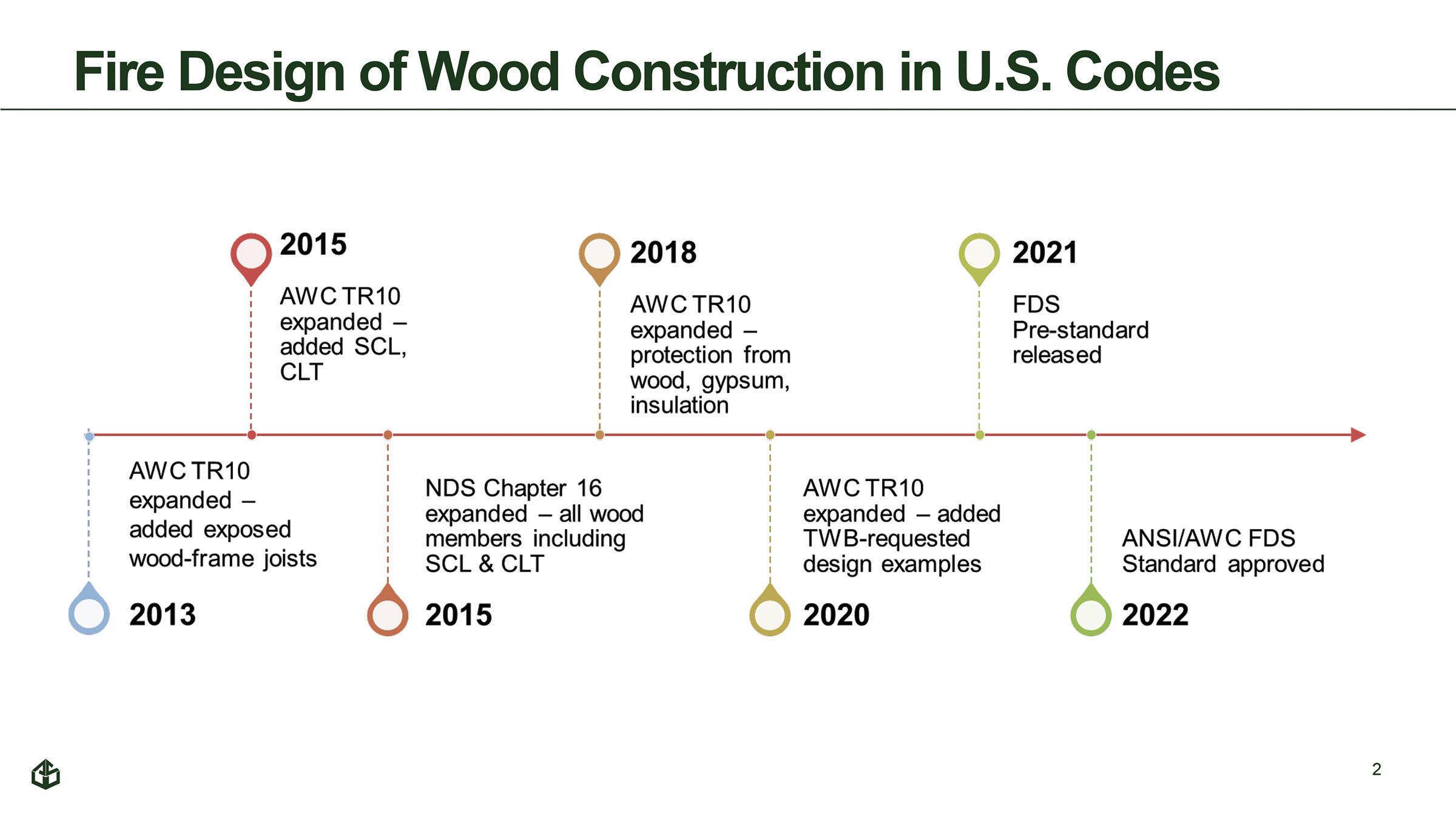 Figure 3. This example shows char penetration where gap is less than or equal to 1/8 inch on the exposed side and where air flow through gap is permitted to be neglected in accordance with FDS 3.2.3.2.
fire-resistance-rated wall assemblies, floor/ceiling assemblies and roof/ceiling assemblies.
Provisions for evaluating the charring of wood as a function of standard fire exposure time are given in Section 3.2. Guidance is given in this section for calculation of char depth on surfaces of exposed wood members, as well as for calculation of char penetration at intersections and abutting edges between wood members. Various possible configurations of intersections and abutting edges are addressed, each associated with unique design guidance. The FDS Commentary provides further clarification, with example details corresponding to each of these possible configurations—one of which is shown in Figure 3.
The 2024 FDS is accessible for free on the AWC website at bit.ly/3UJ29RV
The 2024 NDS is accessible for free on the AWC website at awc.org/publications/2024-nds/.
Section 3.3 is where designers will find provisions for calculation of structural fire resistance of exposed wood members. While these structural fire resistance provisions should be familiar to those who have designed in accordance with previous editions of NDS Chapter 16, they also provide additional guidance, clarification, and design options for fire design of structural glued-laminated timber beams, lumber decking, and CLT. New design guidance is also provided in Section 3.3 for determining effective char depth at bearing interfaces with one or more members bearing perpendicular-to-grain.
Section 3.4 lays out provisions that can be used to quantify protection time provided by various materials, such as additional wood cover, fire-rated gypsum panels and certain types of insulation, when used as protection for the purpose of increasing the fire-resistance rating of a wood member or assembly. As stated in Section 3.5, such protection delays the onset of charring on each protected surface by an amount of time equivalent to the calculated protection time. In this way, calculated fire-resistance ratings exceeding 2 hours are possible for protected wood members and assemblies, even though the calculated contribution of the wood members to the structural fire resistance is not permitted to exceed 2 hours.
The procedures for calculating the thermal separation time and burn-through time provided by an assembly are described in Sections 3.6 and 3.7, respectively. The concepts of thermal separation and burn-through time are used in the design of fireresistance-rated assemblies that are intended to separate one fire area from another. In most cases, thermal separation and burnthrough resistance are provided by adding wood cover, fire-rated gypsum panels, and/or insulation to the assembly. Another application where the concept of thermal separation time is used is in the case of structural connections between members or assemblies that are required to be fire-resistance-rated. As specified in Section 3.10, such structural connections must be covered with protection that is designed to provide a thermal separation time no less than the fire-resistance rating required of the connected members.
Besides the calculation procedures laid out in Sections 3.2 through 3.7, one other procedure for calculating the fire-resistance ratings of assemblies is addressed in Section 3.9. This procedure,
referred to as the component additive method, may be used for calculating the fire-resistance ratings of wall assemblies, floor/ceiling assemblies and roof/ ceiling assemblies having components as described in Section 3.9. Assigned contribution times are provided for various components toward the overall fire-resistance rating of the assembly. These assigned contribution times are consistent with protection times and component fireresistance ratings that would be calculated in accordance with the provisions of Sections 3.2 through 3.5. They are summed, within the constraints of Section 3.9.1, to determine the structural fire resistance time for the assembly. The thermal separation time must also be determined, in accordance with Section 3.9.2, and the fire-resistance rating of the assembly is taken as the lesser of the structural fire resistance time and the thermal separation time. Because this component additive method has been validated for calculation of fire-resistance ratings of assemblies rated for up to two hours, its applicability is not limited to one-hour fireresistance ratings like previous component additive methods.
The 2024 edition of the ANSI/AWC Fire Design Specification for (FDS) Wood Construction , approved as an American National Standard in September 2023, applies to wood construction covered under the ANSI/AWC National Design Specification (NDS) for Wood Construction and provides a new design resource for use where fire design is required by applicable building codes. In addition to containing provisions consistent with those provided in NDS Chapter 16 for fire design of exposed wood members, the 2024 FDS provides new calculation procedures for fire design of protected wood members and assemblies. Because the FDS represents a more comprehensive design standard for fire design of wood construction, it is referenced in NDS Chapter 16 for design considerations that are not fully addressed in NDS Chapter 16. The 2024 FDS is accessible for free on the AWC website at bit.ly/3UJ29RV. The 2024 NDS is accessible for free on the AWC website at awc.org/publications/2024-nds/. ■
Jason Smart, PE, is Director of Fire Engineering with the American Wood Council (jsmart@awc.org).
Bradford Douglas, PE, is Vice President of Engineering with the American Wood Council (bdouglas@awc.org).
John “Buddy” Showalter, PE, is a Senior Staff Engineer with the International Code Council (bshowalter@iccsafe.org).




HIGH-STRENGTH
Design with Aeos™ high-strength ASTM A913 structural steel. A high strength-to-weight ratio means fewer tons and a lower carbon footprint for your project. Aeos is also the lowest embodied carbon steel of its kind, made with more than 95% recycled content using a circular steelmaking process with electric arc furnace (EAF) technology.

This multi-part series discusses significant structural changes to the 2024 International Building Code (IBC) by the International Code Council (ICC). This article includes an overview of changes to IBC Chapter 24 on glass and glazing. Only a portion of the chapter’s total number of code changes is discussed in this article. More information on the code changes can be found in the 2024 Significant Changes to the International Building Code available from ICC.
IBC Section 2407 includes uniform regulations identifying the specific types of safety glazing that may be used structurally. Laminated tempered and laminated heat-strengthened glazing are the only types considered by the code to be structurally adequate under all conditions of installation. Single-layer tempered glass is acceptable under limited applications where there is no walking surface below the glass, or where the walking surface below is permanently protected from the risk of falling glass. Maximum stresses for heat-strengthened and fully tempered glass are now provided for the design of glass handrails and guards, clarifying a previously confusing design requirement.
2407.1.1 Loads. Glass handrails and guards and their support systems shall be designed to withstand the loads specified in Section 1607.9. Calculated stresses in glass elements of handrails and guards due to these loads shall be limited to a maximum of 3,000 psi (20.7 MPa) for heatstrengthened glass and 6,000 psi (41.4 MPa) for fully tempered glass. Glass handrails and guards shall be designed using a factor of safety of four.
Change Significance: Previously, glass handrails and guards and their supporting systems (Figure 1) were required to be designed to withstand the loads as specified in Section 1607.9 utilizing a safety factor of four. An often-asked question was how to apply the safety factor of four. This modification guides those designing glass handrails or guards by providing maximum stresses for heat-strengthened and fully tempered

glass that meet the previously prescribed safety factor. Maximum stress-carrying capabilities of the two types of glass that may be used in the design of glass handrails and guards – heat-strengthened glazing and fully tempered glazing – are published by the glass industry. Heat-strengthened glass can bear stresses of 12,000 psi while fully tempered glass can bear stresses of 24,000 psi. Accordingly, the values now prescribed in Section 2407.1.1 are one-fourth of those maximum stresses. Values of 3,000 psi for heat-strengthened glass and 6,000 psi for fully tempered glass must equal or exceed the calculated stresses for the loads specified in Section 1607.9.
IBC Section 1607.9.1.1 requires that handrails and guards be designed to resist a concentrated load of 200 pounds per Section 4.5.1 of ASCE 7. Further, Section 4.5.1.1 of ASCE 7 indicates that handrail and guard systems shall also be designed to resist a load of 50 pounds per linear foot applied in any direction along the handrail or top rail and transfer this load through the supports to the structure. This load need not be assumed to act concurrently with the 200-pound concentrated load. IBC Section 1607.9.1.2 specifies that guard components including panel fillers and guard infill components are to be designed to resist a concentrated load of 50 pounds per Section 4.5.1.2 of ASCE 7. According to ASCE 7, this concentrated load is to be applied over an area not to exceed 12 inches by 12 inches.
In areas where it is likely that persons will impact glass or other glazing, the IBC mandates that specific glazing materials be installed. These areas, identified in Section 2406.4, are considered by the code as “hazardous locations.” Unless exempted, all glazing located in hazardous locations must pass the test requirements established in Section 2406.2 for impact-resistance. Due to some confusion as to the requirements for glazed assemblies with multiple glass panes, it has been clarified that every pane in such multipane glass assemblies be safety glazing where located in the hazardous locations identified by the IBC (Figure 2). 2406.1 Human impact loads. All glass in Individual glazed areas, including glass mirrors, single panes of glass, laminated glass and all panes in multipane glass assemblies in hazardous locations as defined in Section 2406.4 shall comply with Sections 2406.1.1 through 2406.1.4. Exception: Mirrors and other glass panels mounted or hung on a surface that provides a continuous backing support.

Change Significance: The IBC has always mandated safety glazing for all panes of glass in a multipane
assembly. However, there have been reports of such assemblies where the center pane(s) are non-complying annealed glass surrounded by panes that qualify as safety glazing. The revised code text should help ensure that multipane assemblies installed in hazardous locations are fully safe in the event of human impact and that potentially dangerous annealed panes of glass are not intermingled with safety glazing in multipane assemblies.
IBC Commentary Section 2406.4.3 indicates that the purpose of safety glazing is to "…provide protection where the glazed opening could be mistaken for a passageway or clear opening that someone might be able to walk through, fall into, or otherwise be accidentally forced into." For areas that meet all four criteria listed in Section 2406.4.3, safety glazing is required in a window (Figure 3). The provision also provides exceptions for 1) decorative glass, 2) protection by a horizontal rail and 3) outside panes of insulating glass units (IGU) or multiple layers of glazing.
2406.4.3 Glazing in windows. Glazing in an individual fixed or operable panel that meets all of the following conditions shall be considered to be a hazardous location:
1. The exposed area of an individual pane is greater than 9 square feet (0.84 m2).
2. The bottom edge of the glazing is less than 18 inches (457 mm) above the floor or adjacent walking surface
3. The top edge of the glazing is greater than 36 inches (914 mm) above the floor or adjacent walking surface.
4. One or more walking surface(s) are within 36 inches (914 mm), measured horizontally and in a straight line, of the plane of the glazing.
Exceptions:
1. Decorative glazing.
2. Where a horizontal rail is installed on the accessible side(s) of the glazing 34 to 38 inches (864 to 965 mm) above the walking surface. The rail shall be capable of withstanding a horizontal load of 50 pounds per linear foot (730 N/m) without contacting the glass and be not less than 1.5 inches (38 mm) in cross-sectional height.
3. Outboard panes in insulating glass units or multiple glazing where the bottom exposed edge of the glass is 8 feet (2438 mm) 25 feet (7620 mm) or more above any grade or , roof, walking surface or other horizontal or sloped (within 45 degrees of horizontal) (0.79 rad) surface adjacent to the glass exterior.
Change Significance: Exception 3 was sometimes misinterpreted as triggering the need for safety glazing on the exterior envelope of the building. While not the intent, ground-floor, second-floor, and even third-floor exterior windows up to 25 feet above grade were occasionally being specified or replaced with safety glazing on the outboard panes. It is inconsistent
to have more stringent provisions requiring safety glazing on the exterior surfaces of the building (previously up to 25 feet above a roof or walking surface) than on the building’s interior (required where the glass is less than 18 inches above the walking surface). It is also not consistent to require safety glazing on the building’s exterior when the window is an IGU but not when the glass is single-pane.
This change makes the requirement impartial regarding the concern of falling out of a building, falling into a building, or falling through a window that does not result in a person entering or leaving a building (e.g., an interior window with floor walking surfaces on both sides). It recognizes the need to prevent situations where people on the building’s exterior (whether on a roof or adjacent walking surface) could fall through a window into a building. While this is a less likely occurrence than people falling through windows out of a building, it is a concern where windows are located adjacent to the roof level (for example a clerestory). Where the vertical distance from the bottom exposed edge of the glass to grade or to a walking surface adjacent to the window exterior is less than 8 feet, safety glazing is required on the outboard pane of insulating glass units or multiple layer glazing.
This provision would also apply along a walkway or deck that may be higher than the immediately adjacent walking surface on the other side of the window. However, because the provision had not previously considered the distance to the bottom of the window, it now addresses the concern of people potentially falling into another portion of a building regardless of whether the walking surfaces on either side of the window are at the same elevation. For example, in Figure 3, if a corridor is adjacent to an atrium and there are multiple layers of glazing, only the pane adjacent to the corridor requires safety glazing. The pane adjacent to the atrium is higher than the 8-foot threshold and would not require safety glazing.


Structural engineers should be aware of significant structural changes in the 2024 IBC Chapter 24 on glass and glazing. Maximum stresses for heat-strengthened and fully tempered glass are now provided for the design of glass handrails or guards. It has also been clarified that every pane in multipane glass assemblies be safety glazing where located in the hazardous locations identified by the IBC. Finally, window safety glazing is required where a person could fall through a window—either out of a building or inside the building—or into the building through a window. However, safety glazing is not required on outboard panes of glazing when the height above grade or the walking surface exceeds 8 feet. ■
John “Buddy” Showalter, PE, M. ASCE, M. NCSEA (bshowalter@iccsafe.org) is a Senior Staff Engineer and Sandra Hyde, PE, M. ASCE, M. NCSEA (shyde@iccsafe.org) is Managing Director of ICC’s Consulting Group.
Two experts in high strength, low-alloy steel discuss the advantages, applications, and considerations of using A913 steel in structural engineering design.
By STRUCTURE MagazineASTM A913 is the standard specification for high-strength (up to Grade 80) low-alloy steel shapes of structural quality, produced by thermo-mechanical rolling followed by a quenching and self-tempering process (QST). The ASTM specification covers Grades 50, 65, 70, and 80 for use in buildings, bridges, or other structures.
STRUCTURE Magazine talked with representatives from two steel suppliers to learn more about how A913 is used in building applications, considerations for its use, and overall capabilities.
STRUCTURE: What makes ASTM A913 different from conventional A992 steel? How is it made?
Dennis Pilarczyk: There are several differences between ASTM A913 and ASTM A992 steel, the most relevant of which to the structural engineer is the increased yield strength properties of ASTM A913 steel (up to 80ksi for A913, whereas A992 is typically 50ksi). This gives the designer the ability to support greater axial loads with less material by favoring A913 over A992.
What gives A913 higher strength, as well as improved weldability attributes, lies within the thermo-mechanical control and quenching and self-tempering (QST) processes. QST consists of in-line heat treatment with controlled cooling. During the QST process, intense water cooling is applied to the whole surface of the wide flange section directly after the last rolling pass. The cooling is interrupted before the core is affected by quenching and the outer layers are tempered by the flow of the heat from the core to the surface as the section’s temperature returns to equilibrium.
STRUCTURE: What is the history of A913 steel?
Joe Dardis: Many of the engineers I talk to don’t realize A913 has been around for over 30 years. It was first introduced to the global market by ArcelorMittal in 1990 and was adopted by ASTM in 1993 under the A913 specification.
The original A913 specification included Grades 65 and 70 but was expanded over the years. Grade 50 was added to the specification in 1995 and Grade 80 was added in 2019.
Code acceptance of A913 grew in the 1990s as it was introduced in the American Welding Society (AWS) D1.1 Structural Welding Code in 1996 and included in the AISC Specification for Structural Steel Buildings in 1999. Combined with growing familiarity of its economic benefits among designers, an increased demand for tall buildings, and greater availability, adoption of A913 grew. 30 plus years later, A913 has been used in hundreds of tall (and not so tall) steel buildings and is becoming the standard material for tall steel buildings worldwide.
STRUCTURE: What are the benefits associated with a higher yield strength?
Pilarczyk: The primary benefit associated with higher yield strength can
be found in strength-controlled elements such as axially loaded columns, long-spanning trusses, and short-spanning girders. In these applications, the designer can often realize tonnage reductions from 15-30% when compared to ASTM A992 steel which has a 50ksi yield strength.
While tonnage reductions themselves can have a positive impact on a project from a design efficiency standpoint, there are several other benefits associated with A913. These would include a reduction in embodied carbon due to the elimination of member tonnage, lower crane requirements, smaller supporting and foundational elements, and reduced weld material when conjoining smaller members. These “trickle down” benefits of A913 steel can have a substantial impact on a project by way of reduced labor/material costs as well as schedule efficiencies.
STRUCTURE: How does the alloy content affect the weldability of A913? How does weldability affect economy?
Dardis: Since the thermo-mechanical control and QST processes provide additional grain refinement and strength, A913 is less reliant on conventional alloy-dependent strength enhancement. Subsequently, when compared to A992, A913 has lower carbon and alloy content, providing superior weldability characteristics.
It is important to note the meaning of weldability. Most steels are weldable, but the relative ease in which they can be welded is described as weldability. The better the weldability, the less precautions need to be taken, such as preheating the steel prior to welding.
Due to their superior weldability characteristics, A913 Grade 50 and 65 are prequalified in AWS D1.1 to be welded without preheat across all thickness levels, provided the base metal temperature is above 32 degrees F and the filler metal has a diffusible hydrogen content of 8 ml/100g (H8) or less.
The absence of preheat requirements can significantly reduce fabrication costs, particularly for thicker sections. For instance, A992 steel over 2 ½ inches thick must be preheated to 225 degrees F. This can add hundreds, if not thousands of man-hours on a large project in addition to increased material and energy consumption. Further, preheating can become more complex and costly if it needs to be done in the field.
A913 Grade 70 is also a prequalified base metal in AWS D1.1, albeit with slightly higher preheat requirements than A992 steel. A913 Grade 80 is currently not a prequalified base metal, which means the fabricator must establish their own weld procedure and qualification testing prior to fabricating A913 Grade 80.
STRUCTURE: How does A913 differ from A992 in terms of toughness requirements?
Pilarczyk: The QST process helps to refine the grain structure of A913 steel when compared to A992 steels. Through sophisticated controlled cooling and rolling sequences, grain size is restrained against overgrowth, creating what is called a refined grain structure that improves toughness. The ASTM A913 specification requires a Charpy V-notch (CVN)
impact test meeting a toughness of 40 foot-pounds at 70 degrees F. This CVN requirement is included in the specification and is not a supplementary requirement. On the other hand, CVN testing is always a supplementary requirement for A992.
Additionally, the Supplementary Specification S30 in ASTM A6 can be utilized to get Charpy impact testing at the alternate core location when the flange thickness equals or exceeds 1.5 inches. Lower temperature CVN testing can be achieved, upon request, for applications in extreme environments.
STRUCTURE: In what applications is A913 most beneficial? In what applications is A913 not as beneficial?
Dardis: The most obvious application of A913 is for use in tall buildings. Gravity columns in tall steel buildings often utilize some of the heaviest rolled shapes available.
The use of A913 in tall buildings allows designers to maximize weight savings given the typical large axial column loads and potentially reduce or eliminate the use of built-up sections or reinforced rolled shapes, saving not only on material costs but also fabrication costs. Additionally, the smaller column size inherent to steel buildings is further realized through the use of an even smaller section, allowing the owner to maximize leasable space and potentially increase revenue.
A913 is also regularly used in truss applications. In tall buildings, A913 can be used in outrigger systems or transfer trusses. Similar
The BMO Tower, completed in 2021, is the first project in the U.S. to utilize A913 Grade 80 steel. Structural engineer Magnusson Klemencic and Associates developed an innovative strategy to determine the most costeffective usage of A913 by implementing a triple column schedule, providing designs options for all grades of A913. They then let the market decide the most efficient solution. A913 Grades 50, 65, 70, and 80 were all ultimately used in the final design.


to gravity columns, members in these applications can have high axial loads and designers can take full advantage of the higher yield strength. Long-span trusses in stadiums, arenas, convention centers etc. can also benefit from a higher yield strength and reduced member size. In these scenarios, a reduction of the dead load of the truss is an additional benefit.
Another common application is in seismic design. The higher yield strength can optimize columns in the “strong column-weak beam” design as well as satisfy the sometimes large column strength demands in seismic braced frames.
Given all these benefits, I am often asked why not just use A913 everywhere? While A913 is a great solution in many applications, it won’t help with stiffness requirements. For example, steel sections used for floor framing and lateral systems are often governed by deflection, vibration, or drift. Increasing yield strength and reducing member size will reduce the stiffness of these systems. It is worth noting, however, that in cases where extensive welding is required, A913 Grade 50 can be used in lieu of A992 for weldability benefits.
The new 1,041-foot-tall skyscraper at 66 Hudson Boulevard, commonly known as “The Spiral” features 2.85 million square feet –66 stories – of rentable commercial office space and occupies the block between Tenth and Eleventh Avenues and 34th and 35th Streets in the Hudson Yards area of Manhattan. Developed by Tishman Speyer and designed by architects Bjarke Ingels Group and structural engineers WSP USA, the unique spiral design is achieved by utilizing A913 steel for the structural elements as each floor is framed differently as the building progresses upwards. As noted by WSP USA, “using A913 Grade 65, we were able to not only reduce the tonnage of the building, [we were able to] reduce the column size as well, which allows for more usable space for the clients.”

STRUCTURE: What are the not so obvious applications that the engineering community should be aware of?
Dardis: A rule of thumb that I always tell designers is if your member is strength-controlled and weighs roughly 100 pounds/foot or more, you can save money by utilizing A913. While you will run into this scenario in almost every tall steel building or long-span truss, there are many other projects where this applies.
Multi-story hospitals, labs and higher education facilities will often have higher dead and live loads, long spans, skyways, and assembly spaces with non reducible live loads, which could all contribute to larger loads on members. Similarly, many industrial facilities will have equipment or storage loads. While the weight savings may not be as pronounced as a tall building, A913 can still be used effectively to save material and reduce fabrication costs in these types of applications when strength is governing the design.
STRUCTURE: What is its acceptance in codes and standards?
Dardis: A913 Grade 50, 65, 70, and 80 are approved materials in the AISC 360 –22 Specification. A913 Grade 50, 65 and 70 are approved materials in the AISC 341 –22 Seismic Specification with some limitations.
AISC 341 permits the use of A913 Grade 50 in any part of the seismic force resisting system provided that a max yield to tensile ratio is specified (supplementary requirement S75). A913 Grade 65 and 70 are permitted for use in column sections where the steel is not expected to yield, such as special moment frame and braced frame systems.
STRUCTURE: Is it available? Who makes it and in what shapes and grades? Is there a longer lead time than A992?
Pilarczyk: A913 steel is produced domestically by Nucor at the NucorYamato Steel Company facility in Blytheville, Arkansas. This mill is capable of supplying A913 in Grades 50, 65, 70, and 80 for wide flange products, including jumbo sections.
Since the process to create A913 steel with the quenching and self-tempering (QST) is in-line with traditional A992 steel, it is produced in the same roll cycles and frequency as any other wide flange products. It should be noted that, due to the QST process, a minimum amount of thickness must be present in the steel section’s web and/or flange. If there is not enough thickness in the web or flange, the rapid cooling will quench the entire cross-section of the steel and not allow for adequate self-tempering to occur. As such, not all wide flange sections are available to meet the A913 specification. For example, a W14x90 is the smallest section available in the W14 family. Please consult your Nucor or ArcelorMittal representative to gather all available sections. Dardis: ArcelorMittal produces A913 Grade 50, 65, 70 and 80 for the North American market at its Differdange mill in Luxembourg. ArcelorMittal rolls A913 in shape sizes up to W14x1000 and W36x925.
STRUCTURE: What are the sustainability benefits? Is there a difference in embodied carbon for A913 versus A992?
Pilarczyk: Fundamentally, due to the in-line nature of A913 production, the embodied carbon required to produce it does not differ from A992 steel. All A913 steel is produced in steel mills that utilize electric arc furnace (EAF) technology. This is the cleanest process available to make steel and is reliant on a feedstock of scrap material to make new steel out of old steel in a circular manner.
However, substantial sustainability benefits can be realized when using higher strength A913 steel versus 50ksi A992 steel. When higher strength steel is used to reduce the member size required for column, truss, or

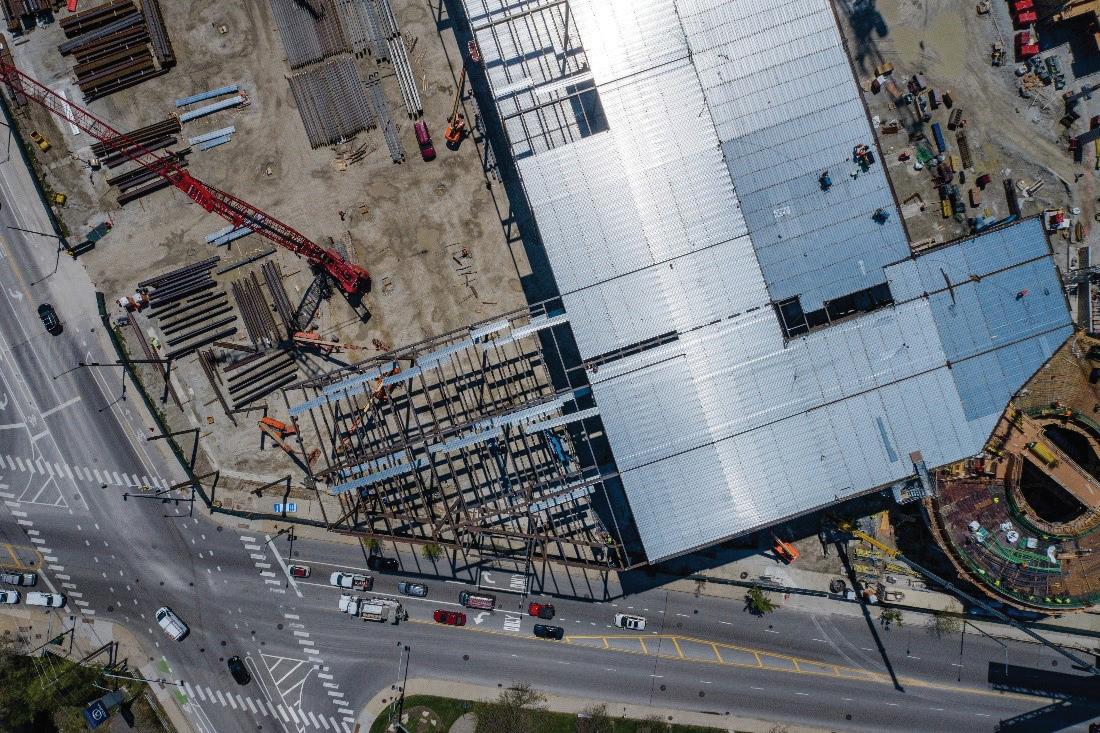
A two-story distribution center project in the Midwest utilized A913 Grade 65 steel in an construction type that would not traditionally consider higher strength structural steel. Structural engineer DCI Engineers, realized A913 Grade 65 steel was the preferred choice to support the loading conditions present with an elevated warehouse floor and rooftop parking. The use of A913 steel saved approximately 165 tons of steel material. Additionally, the design team prioritized embodied carbon savings for this project and, through the combination of efficient design practices and procurement strategies, found 1,063 metric tons of CO2-equivalent savings.
short span girder elements, the embodied carbon is similarly reduced. Remember the global warming potential of steel is typically expressed in terms of the carbon dioxide needed to produce a ton of steel. For example, if a W14x605 A992 Grade 50 member is required to support the anticipated loading conditions for a column element, then switching to a W14x500 A913 Grade 65 will reduce embodied carbon by over 17%. Multiply this across an entire project and it becomes apparent how substantial the savings may be. Greater reductions can be expected when utilizing A913 Grade 80 wide-flange sections.
STRUCTURE: What changes should we look out for in the near future?
Dardis: ArcelorMittal has done extensive research and testing on the weldability of A913 Grade 70 and 80 and has successfully demonstrated that the prequalification status of these grades should be reviewed. As a result, there will be significant changes effective with the release of AWS D1.1 2025.
The minimum prequalified preheat temperatures of A913 Grade 70 will be reduced and match A913 Grade 50 and 65 up to a material thickness of 2 ½ inches. Above 2 ½ inches, the minimum preheat will be reduced from 300 degrees F to 150 degrees F (electrode classification H8 or lower). In addition, A913 Grade 80 will be introduced as a prequalified base metal with the same preheat requirements as A992 (electrode classification H4 or lower).
This will have a dramatic effect on the overall economy of using these grades. Designers will be able to better utilize the improved weight savings of the stronger grades, while worrying less about the trade-offs in fabrication cost due to the more stringent preheat requirements.
Pilarczyk: Many changes are on the horizon when it comes to A913 steel, but also for the steel industry as a whole. A913 Grade 80 steel is becoming more available in the market, in sizes that have not existed in the past. It was mentioned earlier that electric arc furnaces (circular steelmaking) is the cleanest way to produce steel, however substantial efforts are underway to continue pushing the boundaries for how we can decarbonize the industry. Using fusion, fission, and hydrogen technologies (among others) to displace fossil fuel energy sources are exciting developments to monitor.
Market demands are a major driving force for steel manufacturers to understand what solutions are needed to meet the challenges the design and construction communities are facing. It is important for the design, construction, and fabrication communities to communicate early and often with steel manufacturers to ensure the latest innovations are being employed in projects for more efficient, sustainable outcomes.
STRUCTURE: What is the cost premium, if any, for A913? Can that premium be offset in another area?
Dardis: The efficiency of the QST process means that steel manufacturers can produce A913 without a significant increase in cost. As a result, the premium on A913 is minimal and can easily be overcome by the weight savings.
Steel is bought on a basis of weight, so weight savings directly translate to dollar savings. If A913 reduces tonnage by 15-30%, there is a huge net savings even by the most conservative estimates. If you add in the other benefits, such as lower preheat requirements and reduced fabrication costs, the net savings gap widens.
STRUCTURE: What resources are available to assist design teams?
Pilarczyk: Both Nucor and ArcelorMittal—the two sources of A913 steel—have technical information available to provide guidance when designing, procuring, and working with A913 steel. However, possibly more relevant is the call to action for the design and construction communities to establish relationships with their steel suppliers. Early collaboration can net considerable benefits for the project team. ■
As Earth Month comes to an end and summer approaches, SEI continues to advance the profession’s understanding of how to mitigate the impacts from the changing climate on our built environment. Considering both adaptation and mitigation, SEI committees and members are working hard and leading the way in development of new design approaches, resources, and tools to combat climate change and create safer, more sustainable and resilient infrastructure. ASCE 7-22 Supplement #2 includes extensive revision to Chapter 5 Flood Loads, including a requirement for coastal locations to consider sea level change; the Supplement is

Back in March, SEI continued the tradition on Instagram at SEICON24 with a SEI Futures Fund Scholarship Winner Takeover. This exciting milestone for our social page underscores the tremendous success of the 2024 SEI Futures Fund activites, as we reached our highest number of scholarship
available at www.asce.org/asce7 as a free download.
The ASCE/SEI 7 Standard Committee is leading the way with evaluation of how structural loads may be evolving—the ASCE/SEI 7-28 Future Conditions Subcommittee is evaluating climate-informed environmental hazards that may be appropriate for inclusion in the next edition of the national loading standard.
SEI’s commitment extends beyond standards development, however, with initiatives like SEI SE 2050, which exemplifies a holistic approach to structural engineering. SEI SE 2050 Commitment Program Signatories aims to transform the practice by prioritizing the

recipients. This year’s Instagram takeover winner, Makenna Brown, provided a glimpse into how the SEI Futures Fund scholarship impacts students. Makenna took us from networking events to career-building education sessions, offering an insider’s look into her experience. Makenna’s takeover exemplified
reduction of embodied carbon using less impactful materials, along with other strategies; learn more at www.SE2050.org.
By integrating sustainability goals such as those of SEI SE 2050 into our work, including the upcoming workshop in July, we aim to have a proactive approach to addressing climate challenges and fostering a sustainable future for the welfare of communities worldwide.
In fact, SEI is hosting an in-person workshop on July 23-24 in Boston titled “Towards Zero Carbon: Developing a Roadmap for the Structural Engineering Profession and the Structural Engineering Institute, ASCE”—visit www.asce.org/sei for more information and to register for free.

how the SEI Futures Fund empowers students and provides them with an exciting view of the industry. Join us in continuing is tradition and help shape the future of structural engineering by donating today.
Learn more at www.asce.org/ SEIFuturesFund.
Following the publication of ASCE/SEI 41-23 Seismic Evaluation and Retrofit of Existing Buildings, the committee is reconstituting its roster to begin work on the 2029 edition. ASCE/SEI 41 is now accepting new members for the next edition of the standard. Applications are being accepted until September 1, 2024. Apply with the QR code—select SEI from the Institute drop-down, and then select the standard title.

SEI is currently accepting proposals to modify the 2022 edition of ASCE/SEI 7 Minimum Design Loads Associated Criteria for Buildings and Other Structures, as the committee prepares for 2028 revision cycle.
The committee will accept public proposals until December 1, 2024. The Public Proposal Form is available from SEI via sei@asce.org.
Sign up to receive the SEI SE 2050 newsletter and learn how you can contribute towards zero embodied carbon structural systems by 2050. Learn more about the SE 2050 Commitment Program, how to join, and explore tools and educational resources at www.SE2050.org.

The new SEI publication, “Structural Condition Assessment of Existing Buildings (Manual of Practice No. 158),” represents an adaptation of the well-used ASCE/ SEI Guideline for Structural Condition Assessment of Existing Buildings (ASCE/ SEI 11-99). This comprehensive manual offers up-to-date guidelines for conducting building condition assessments, focusing on aspects crucial to understanding the structural integrity of existing buildings. MOP 158 is an invaluable resource for engineers and professionals involved in assessing and maintaining the safety and reliability of built structures. Preorder of MOP available now for members at: https://sp360.asce. org/personifyebusiness/Merchandise/ Product-Details/productId/313259242.


In the wake of the devastating collapse of the Francis Scott Key Bridge, a vital artery connecting Baltimore communities since 1977, this curated collection of papers delves into maritime accidents and bridge failures. These scholarly resources, accessible to registered users until June 15, 2024, offer invaluable insights into similar incidents. View the collection at https://ascelibrary.org/key-bridge-collection.
Register for ASCE’s Structural Earthquake Engineering for Buildings Certificate Program to gain career-focused skills directly from industry professionals and university professors. Master earthquake engineering fundamentals, seismic analysis, and structural design for both new and existing buildings while saving up to 20% on enrollment. Earn 10 PDHs for 5 on-demand courses within 1 year of enrollment. Visit here for more: https://mylearning.asce.org/diweb/catalog/item/ eid/236875382
“The growth of the NCSEA Foundation Diversity in Structural Scholarship program, from four scholarships in 2021 to 25 in 2024, is an incredible endorsement from our profession to the Foundation’s mission.”
—Tricia Ruby, NCSEA Foundation Board of Directors President
Congratulations to the 25 recipients of the 2024 Diversity in Structural Engineering Scholarships! The NCSEA Foundation experienced a record-breaking year, doubling the number of scholarships distributed. These scholarships, ranging from $3,000 to $5,000, support historically underrepresented students pursuing careers in structural engineering. This year, the Foundation will award over $70,000 in scholarships, a 50% increase over 2023, thanks to the support of twelve groups and industry partners. A special thank you to Computers and Structures, Inc. (CSI) for their generous donation to the NCSEA Diversity in Structural Engineering Scholarship program, supporting the scholarship recipients and their NCSEA Summit experience. The program received 147 applications this year, eclipsing last year’s 101 submissions and almost tripling the number of applications in 2021, the scholarship program’s first year. The high caliber applicants hail from 30 different states and span the spectrum of race, ethnicity and gender. Comprised of 20 NCSEA community members, practicing structural engineers and engineering hiring specialists, the Scholarship Review Committee has reviewed the applications, and announced the following selected recipients:
• Applied Technology Council Diversity in SE Scholarship—Eduardo Montalto
• Degenkolb Engineers Diversity in SE Scholarship—Maria Emilia Clavijo Calderon
• Forell | Elsesser Engineers Scholarship—Geraldine Lynch
• Holmes Diversity in SE Scholarship—Divino Gonzales and Edwin Reyes
• Mackenzie Diversity in Engineering Scholarship—Liana Wong
• Martin/Martin Skyrise Scholarship—Ana Mateo Jerez
• SEA-MW Diversity in SE Scholarship—Damario Berry
• SEAONC Diversity in SE Scholarship—Sarah Soto
• SEAoNY Diversity in SE Scholarship—Ibrahima Fall
• Steven B. Tipping Memorial Scholarship for Innovation and Excellence in SE—Khanh Doan
• Wood Solutions Scholarship sponsored by Think Wood—Afeez Badmus, Baiyu Chen, Ronald Orellana and Tiana Noelani Thorp
• NCSEA Diversity in Structural Engineering Scholarships—Alberto Diaz Lozas, Emily Cheng Kerstetter, Emily Cross, Grace Lynn Pluemacher, Javier Andres Chininin, Leon Crawford, Santa Flores Alvarez, Shun Lei Yee, Tyler Kleinsasser and Victoria Abigail Maidana Dure
“The growth of the NCSEA Foundation Diversity in Structural Scholarship program, from four scholarships in 2021 to 25 in 2024, is an incredible endorsement from our profession to the Foundation’s mission as we seek to provide support for historically excluded members of our community to this great profession,” said Tricia Ruby, NCSEA Foundation Board of Directors President. “We recognize that diversity is essential in strengthening our structural engineering community and achieving greater diversity requires intentional support.”
The Diversity in Structural Engineering Scholarship Program was established in 2021 by the NCSEA Foundation to award funds to structural engineering students who identify as historically underrecognized students (including but not limited to Black/African Americans, Native/Indigenous Americans, Hispanics/Latinos or Spanish, Asian, Native Hawaiian or Pacific Islander, and other people of color, those with disabilities, veterans and LGBTQIA+). These scholarships help remove obstacles to pursuing a career in structural engineering.
For more information about funding a named or endowed scholarship or donating, visit the NCSEA Foundation website, www.ncsea.com/ foundation.
On May 9-10, the STRUCTURE Magazine Editorial Board convened in Chicago for a productive meeting. While many of the board’s 16 members attended in person, some participated virtually. During the meeting, members reviewed magazine production best practices and explored advancements in the media and publishing industry. They also discussed the question, “How will STRUCTURE change and innovate to continue to be the premier resource for the structural engineering profession of the future?”
The board addressed practical planning tasks for the coming year, created an editorial calendar for 2025, and brainstormed article topics and potential authors. The board, composed of representatives from NCSEA, SEI, and CASE, brings a wealth of experience and perspectives to these discussions.
Do you have an article idea for STRUCTURE? Would you like to write an article? Explore the Author Resource page at www.structuremag.org, or email production@structuremag.org.
Registration is now open for NCSEA’s highly anticipated Structural Engineering Summit, to be held November 5-8 at the MGM Grand Hotel in Las Vegas. With nearly 100 summit abstracts received, this event promises to be a pinnacle gathering for structural engineering professionals. Prepare for an unparalleled technical education experience as NCSEA showcases a fantastic slate of sessions covering cutting-edge topics, innovative technologies and industry insights. Secure your spot at this premier event where knowledge meets networking in the heart of the entertainment capital of the world. Don’t miss out on this opportunity to elevate your expertise and connect with peers in the field. For more information and to register, visit www.ncseasummit.com.
For over a decade, NCSEA has provided scholarship opportunities for Young Members and Young Member Groups to cover expenses associated with attending the Structural Engineering Summit. Submissions are due June 24.
First-time Young Member scholarship recipients receive complimentary Summit registration as well as a travel stipend of $1,000 to use toward transportation and hotel costs. Previous Young Member scholarship recipients will receive complimentary registration for the Summit.
As part of our commitment to nurturing young talent, NCSEA will also continue to offer the Young Member Group of the Year award. This accolade recognizes an exceptional Young Member Group (YMG) affiliated with one of the Structural Engineering Associations (SEAs). Finalists will receive complimentary registration and a $1,000 travel stipend to send a representative to the Structural Engineering Summit. The winning Young Member Group will be announced at the Summit and will receive an additional $2,500 for their Young Member Group to use for future activities.
NCSEA encourages all who qualify to learn more and submit applications at www.ncsea.com/education-events/events-conferences/ awards/ym-scholarships/.
Travel stipends for the 2024 Young Member Summit Scholarships are generously sponsored by Computers & Structures, Inc.
Visit www.ncsea.com/education for the latest news on upcoming webinars and other virtual events.
30
Purchase an NCSEA webinar subscription and get access to all the educational content you’ll ever need! Subscribers receive access to a full year’s worth of live NCSEA education webinars (25+) and a recorded library of past webinars (170+) – all developed by leading experts; available whenever, wherever you need them!


CASE has committees that work together to produce specific resources available to members, from contract documents to whitepapers, to help your business succeed.
If you are a member of CASE, all CASE publications are free to you. NCSEA and SEI members receive a discount on publications. Use discount code - NCSEASEI2022 when you check out.

Check out some of the new CASE Publications …
In today’s world, survey after survey has listed flexible work schedules and work location as a top desire of employees at all levels. Many companies are currently struggling through this shift and trying to determine what works best for the company in the long term as there are many pros, cons, and important considerations. In addition, structural engineering firms are having more difficulty filling positions and expanding the candidate pool beyond the local office locations could yield high quality employees. These options do create business, insurance, technical, IT/security, productivity, training/mentoring and cultural challenges. This Tool attempts to provide some guidance in these areas.
A critical component of talent management is succession planning. Training, development, career planning (employee-centered), career management (organization-centered), and replacement planning are all key elements of succession planning. Successful succession planning helps an organization cope with talent scarcity, identify skill gaps and training needs, promote knowledge transfer to retain institutional knowledge, increase morale and retention by investing in employees, and create bench strength for unique and highly specialized skill sets.
This tool provides guidelines and tips for the verification of analysis and design software results. It focuses on linear elastic structures and small deformation/small strain analysis which represent the vast majority of design office work.
An important aspect of a joint project pursuit between a contractor or design professional and a structural engineer is an agreement covering the activities of the parties prior to contract award. This agreement is commonly referred to as a teaming agreement. Teaming agreements are often associated with design-build projects but can be used on any project pursued jointly by two or more parties. Many organizations familiar to structural engineers provide a standard form teaming agreement. This commentary summarizes the contents and typical clauses of the standard form teaming agreements offered by these four organizations:
• American Institute of Architects (AIA): Contract C102-2015
• Engineers Joint Contract Documents Committee (EJCDC): Contracts D-580 and E-580
• Design-Build Institute of America (DBIA): Contract No. 580
• Consensus Docs: Contract Nos. 296 and 498
You can purchase these and other Risk Management Tools at https://www.acec.org/member-center/get-involved/coalitions/case/resources/
Is there something missing for your business practice? CASE is committed to publishing the right tools for you. Have an idea? We’d love to hear from you!
The Coalition of American Structural Engineers welcomes new leadership on its Executive Committee. At the 2024 ACEC Annual Convention and Legislative Summit, Tina Wyffels, PE, BKBM Engineers, moved to the Chair position and Anthony LoCicero was voted Chair-elect. These new leaders bring a wealth of experience as structural engineers and as committee members of the coalition. Bruce Burt, Ruby + Associates, a Degenkolb Company, moved into the Past Chair position. Thank you to Bruce for serving as Chair for the last year and to everyone who voted for our CASE Executive Committee.
Chair: Tina Wyffels, BKBM Engineers
Chair-Elect: Anthony LoCicero, Burns Engineering
Past Chair: Bruce Burt, Ruby + Associates, a Degenkolb Company
Andrew Dolan, Gilsanz Murray Steficek
Matthew McBruce, ARW Engineers
Justin Naser, ARW Engineers
Roger Parra, Degenkolb Engineers
CASE has several committees that meet regularly to develop documents that help guide engineers in their business practice. Committee member commitments include a monthly virtual meeting, a few hours a month working on relevant documents, and travel to the Coalitions winter and summer meetings. Committees include Contracts, Guidelines, Programs, and Toolkits. If you are interested in serving on a committee, please email coalitions@acec.org.

The manufacture of semiconductors requires robust and careful structural design to protect high-precision processes.
By Brad Cheshire and David BrownS
emiconductors play a central role in almost all consumer goods produced today. Chips are integral to appliances, vehicles, computers, smartphones, ATMs, medical equipment, and more. The industry must double semiconductor production to keep pace with future demand, according to 2023 report by McKinsey & Company, “Semiconductor Fabs: Construction Challenges in the United States.” As a result, many companies have announced plans to build new semiconductor wafer fabrication plants (fabs), with several already under construction. Federal funding from the U.S. Chips and Science Act has accelerated this production boom.
From robust foundations to support heavy equipment and vibration isolation to cleanrooms and temperature and humidity control, the structural design of these facilities is complex. Structural engineers and architects must evaluate many factors to ensure fabs meet the stringent precision and reliability requirements of such manufacturing plants.
As semiconductor chips have become smaller and more powerful, the line widths of the circuitry have been drastically reduced. Chips are now being manufactured with 7 to 14 nanometer line widths in many cases, which is far smaller than a human hair that averages 80,000 to 100,000 nanometers wide. This miniature architecture requires special attention to the structural systems and vibration isolation to make it possible to manufacture them. The impact of humans working in the cleanroom, electrical sources, mechanical sources, and even ambient sources of vibration such as highways and railroads outside the facility must be considered. Structural systems must be stiffened to prevent vibration. Large equipment such as that found in the Central Utility Plants must be separated and isolated from the cleanrooms and piping, and other
utility systems must be spring-isolated to prevent transmission into the structures. Semiconductor tools must also be supported on special bases to reduce vibration. Every source of vibration, both internal and external, to the cleanroom must be identified and addressed.
Cleanroom structural design involves the implementation of airtight enclosures, advanced filtration systems, and airflow control mechanisms to maintain specified cleanliness levels. The choice of construction materials is crucial to prevent the generation of particles, and the structural support system should allow for the installation of complex HVAC systems that can regulate temperature, humidity, and particles that may impact production. Flooring and wall surfaces should also be non-porous and resistant to chemical damage to prevent even minor disturbances.
The goal to limit human contact in the wafer production process has given rise to automated material handling systems, where manufacturers of robotic networks aim to enhance efficiency. These configurations are evolving to deliver individual wafer packages precisely when and where needed within the factory. Stockers, or temporary storage shelves once inefficiently stationed on the floor, are now hung from the ceiling to save space. Robots can drop front-opening universal pods into a designated storage spot along a track, giving way to a streamlined and responsive material handling process. This shift, however, requires the design of roofs and supporting structures to accommodate heavier loads as the weight distribution of valuable semiconductor products changes from resting on the floor to hanging from overhead systems.
The increasing frequency of extreme weather events and climate change have led designers to prioritize resiliency, strength, and durability when building fabs. Optimizing source materials (concrete, steel, timber, etc.) and minimizing waste is critical to future-proofing these facilities. Considering insulation thickness or incorporating lower-carbon cement or recycled steel into early design stages can help ensure structural sustainability.
Facilities also run millions of gallons of water through their systems daily to cool machinery and ensure contaminant-free wafer sheets. These water-intensive processes require innovative water reclamation and storage solutions. To support green building initiatives and adhere to environmental standards, some chip makers must build water recycling facilities to help support their operations. Many semiconductor plants also include infrastructure to store large quantities of water to reduce the impact of their peak demands on the local water supply.
Semiconductors are essential to society. With the continued growth of chip manufacturing, architects and structural engineers must work together to build facilities that meet their unique spatial needs and ensure the structural integrity required for high-precision processes. ■
Brad Cheshire is Principal and Director of Structural Engineering at Page Southerland Page.
David Brown is also Principal and Director of Structural Engineering at Page Southerland Page.
ASDIP Structural Software
Phone: 407-284-9202

Email: support@asdipsoft.com
Web: www.asdipsoft.com
Product: ASDIP SUITE
Description: ASDIP Suite includes the design of beams, columns, walls, base plates, anchor rods, shear lugs, retaining walls, moment connections and more, per the latest design codes. For over 30 years, we have developed powerful yet simpleto-use software tools to easily analyze, design, optimize and check your structural members.
DYWIDAG
Phone: 630-739-1100
Email: sales.us@dywidag.com
Web: www.dywidag.com
Product: DYWIDAG High-Strength Reinforcement THREADBAR Systems
Description: DYWIDAG THREADBARS for significant savings versus conventional reinforcement. Realize less congestion and stronger reinforcement. Reduce the number of bars, enable easier concrete placement and smaller columns resulting in more usable/sellable floor space. Threaded bars and accessories for fast/easy construction. Use GR100 for up to 65% weight and 35% labor reduction.
ENERCALC, LLC
Phone: 800-424-2252
Email: info@enercalc.com

Web: https://enercalc.com
Product: ENERCALC SEL/ENERCALC 3D
Description: Designing tall buildings in complex systemic design software? Sure. Using that same software for spot checks? Not so fast—literally. Tall buildings have thousands of component elements requiring the development of component / cladding wind loads, and code checks that systemic design software doesn’t often support. ENERCALC does this.
The Masonry Society
Phone: 303-939-9700
Email: info@masonrysociety.org
Web: www.masonrysociety.org
Product: Masonry Standards Online
Description: Masonry Standards Online provides easy access to TMS standards from anywhere with enhanced commentary, additional features, and multi-user access. Features include copying, printing, highlighting, annotating, internal linking, links to references and other TMS resources, helpful notations and definition tool tips, and advanced search options.
RISA Tech, Inc.
Phone:949-951-5815
Email: info@risa.com
Web: risa.com
Product: RISA-3D
Description: RISAFloor, RISA-3D, and ADAPTBuilder form an unrivaled multistory building analysis and design package. Modeling has never been easier whether you’re doing a graphical layout, importing a BIM model (from Revit), or prefer spreadsheets. Full code checks and optimization for six different material types makes RISA your first choice in buildings.
SAFI Structural Engineering Software
Phone: 800-810-9454
Email: sales@safi.com
Web: www.safi.com
Product: SAFI GSE Software
Description: Optimize workflow efficiency with the GSE software's hybrid solution enabling simultaneous material design, including steel, cold-formed steel, concrete, automated slab design, timber, light-frame wood and aluminum. Experience a technology built on a powerful user-friendly interface offering advanced structural analysis capabilities and intuitive modeling features. GSE Software: Empowering Engineers since 1986.
Effective risk management requires consideration of potential liabilities from issues that aren't due to design errors.
By Joe DiPompeo, PEAny engineering firm that takes on a new type of project, or even a familiar type of project with unfamiliar parameters is assuming elevated risk. An experienced engineer will understand and apply relevant codes and standards and any additional design criteria that are provided. But from a risk management standpoint the engineer must look beyond the givens and consider the unknowns. What isn’t known about the new project? What critical information hasn’t been provided?
My company has been in business for over 20 years and risk management has always been a priority; because of this we managed to go 20 years without paying a claim. But due to a failure to consider the unknowns on a recent project our streak ended.
In this case our firm designed a warehouse in a floodplain which required an elevated floor, in accordance with the building code and criteria provided by the client and architect. Although warehouse floor load criteria is provided in ASCE 7/IBC, the demands of the equipment that would be used to handle the warehoused material was never relayed to the design team. In fact, the Owner had asked us to check the already designed floor for a specific loading, which we did, and never indicated any use of equipment on the floor. Eventually, the performance of the floor resulting from the use of material handling equipment proved to be an issue as the concrete slab cracked and crumbled in the heavily trafficked areas. The design team’s insurance carriers wanted to settle for the cost of the new floor (to be shared among design professionals), rather than risk larger business interruption costs. It all moved very quickly and just like that we had paid our first claim on a floor that everyone involved agreed met IBC and ASCE 7 live loading requirements. In discussing the specifics with the CASE Contracts Committee for this article, the issue was referred to as a “soft error” because there was no design error, and the design was code compliant. While our standard contract that we entered with our architect client limited liability and consequential damages, the architect’s contract with the Owner had the potential to expose us to additional risks. This was another lesson learned and could be its own article someday. That got me thinking about other incidents through the years that had involved insurers and attorneys. In general, most of these were soft error claims—meaning there was no failure or error in design. The most significant involved a building that was open and operating with no signs of issues or distress. An owner-tenant disagreement involving square footage and rent spiraled out of control and all the design professionals were brought into the dispute.
There are many ways to get in trouble without making a design error. As engineers we strive to stay alert to these soft errors and mitigate them. To borrow Donald Rumsfeld’s famous line, we can often find the foreseeable “known unknowns” through a pre-project review process. But what about the “unknown unknowns”—things that are unforeseeable or are a unique combination of factors unfamiliar to your company. For example, you may have designed several different components of projects many times but never in combination or usage on a given job. Is there anything you do not realize when taking things that you’ve done before but combining them in a new way?
My firm has designed countless numbers of warehouse floors and raised framed floors, so this project did not seem outside our realm of experience. The owner gave no specific criteria for the floors performance, flatness, etc. and the specific criteria they gave us for loading did not include the
equipment. The slabs on grade in the other sections of the warehouse were not in good condition and had similar cracking and damage yet were in no risk of collapse since they were on grade. However, in almost every prior project the warehouse floor was slab-on-grade (thus making dynamic forklift loads much less likely to be an issue). On this project the unique factor was that the floor was to be raised several feet above grade. Who is responsible for the omission in project criteria? The client could have provided better usage information, the architect could have asked more questions, and so could have the engineer. But nobody did. My firm has experience designing warehouse floor slabs-on-grade, as well as raised framed floors; we know there are special design provisions required for a raised floor supporting large, concentrated loads. What was missed was putting it all together. This is one example of a "known,” but at the time the combination of circumstances resulted in an unknown. How do we minimize our liability for other instances of unknown unknowns?
Here are other examples of “unknown unknowns”: Could your project influence not just the adjacent structure, but a structure two properties away? Can local news about a proposed rule change put your firm on the hook for performance requirements not yet provided in building codes? Is there a “backstory” to the project, site, owner, or anyone else involved in the project that may unfavorably affect the end result? Being held responsible for these unlikely scenarios may seem unfair, but the litigation process may not make your limits of responsibility appear as clear-cut as they seemed in the design phase.
Effective risk management requires consideration of potential liabilities resulting from soft errors and unknown unknowns. How can we come to know more, and reduce the risk from what we don’t know?
• Knowing more starts with screening and vetting clients and projects. Firms should develop a process for this and involve as many people within the firm as appropriate. The combined experience of a company is valuable in thinking through things that one or two individuals may miss.
• When generating a proposal for a project, more time needs to be spent thinking through issues. Having a process and involving many people helps.
• A well-written contract or project information sheet filled out by the client that clearly establishes or references design criteria can help, but as our firm found out, this might not be enough to prevent a judge, jury, or arbitrator from concluding you should have done more.
• Gathering information about the project, client, and the project’s end use is obviously critical and should be a more thorough process than just accepting the information given. Discussions with the architect and owner, both formal and informal, can help reveal intents not provided in a request for quotation. These discussions can lead to value added to a project, resulting in a happier client and less risk exposure for the engineer.
Identifying the thing that you don’t know is not an impossible task, but requires client communication, attentiveness, and relying on available expertise to expose potential pitfalls. Careful thought and some additional time upfront can make the "unknown unknowns” better known. ■
Joe DiPompeo, PE, F.SEI, F.ASCE, is the founder and president of Structural Workshop, celebrating 20 years in business, and SEI Past President 2020-2021. He is a member of the CASE Contracts committee, with whom this article was written.


