

Stronger. Simpler. More versatile.
The new Simpson Strong-Tie® Strong-Wall® high-strength wood shearwall.
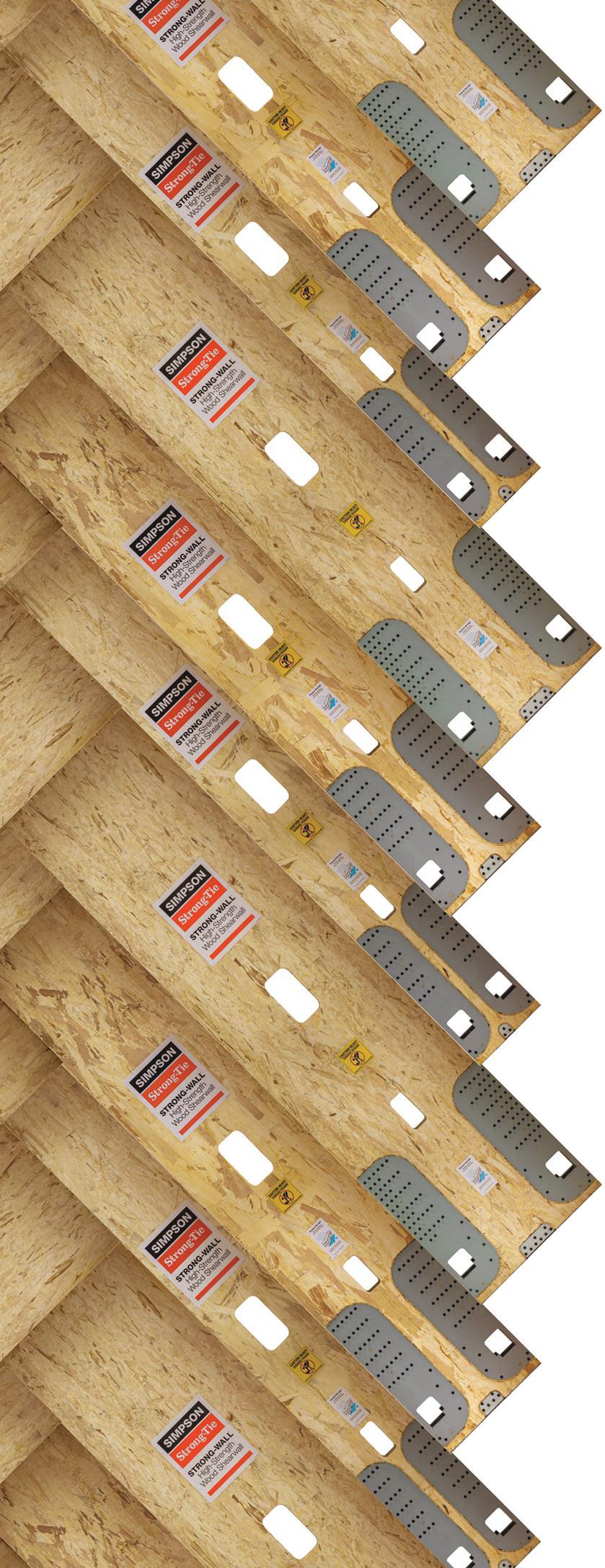
Our latest wood shearwall is a high-performance, extremely versatile solution for lateral-force resistance in light-frame residential and commercial construction. With a patented new design that provides the highest allowable loads across a wide variety of applications, the Strong-Wall high-strength wood shearwall is code listed for easy specification. And it’s field-trimmable for maximum design flexibility and customization. Our Strong-Wall Shearwall Selector web application can help you choose a code-compliant shearwall solution that best suits your project designs.
To learn more about how the Strong-Wall high-strength wood shearwall (WSWH) can simplify and optimize your next design, visit go.strongtie.com/wswh or call (800) 999-5099. S W SS
EDITORIAL BOARD
Chair John A. Dal Pino, S.E. Claremont Engineers Inc., San Francisco, CA chair@STRUCTUREmag.org
Jeremy L. Achter, S.E., LEED AP ARW Engineers, Ogden, UT
Erin Conaway, P.E. AISC, Littleton, CO
Linda M. Kaplan, P.E. Pennoni, Pittsburgh, PA
Charles “Chuck” F. King, P.E. Urban Engineers of New York, New York, NY
Nicholas Lang, P.E. Vice President Engineering & Advocacy, Masonry Concrete Masonry and Hardscapes Association (CMHA)
Jessica Mandrick, P.E., S.E., LEED AP Gilsanz Murray Steficek, LLP, New York, NY
Jason McCool, P.E. Robbins Engineering Consultants, Little Rock, AR
Brian W. Miller Cast Connex Corporation, Davis, CA
Evans Mountzouris, P.E. Retired, Milford, CT
Kenneth Ogorzalek, P.E., S.E. KPFF Consulting Engineers, San Francisco, CA (WI)
John “Buddy” Showalter, P.E. International Code Council, Washington, DC
Eytan Solomon, P.E., LEED AP Silman, New York, NY
Jeannette M. Torrents, P.E., S.E., LEED AP JVA, Inc., Boulder, CO

EDITORIAL STAFF
Executive Editor Alfred Spada aspada@ncsea.com
Production production@structuremag.org
MARKETING & ADVERTISING SALES
Director for Sales, Marketing & Business Development Monica Shripka Tel: 773-974-6561 monica.shripka@STRUCTUREmag.org
STRUCTURE ® magazine (ISSN 1536 4283) is published monthly by The National Council of Structural Engineers Associations (a nonprofit Association), 20 N. Wacker Drive, Suite 750, Chicago, IL 60606 312.649.4600. Periodical postage paid at Chicago, Il, and at additional mailing offices. STRUCTURE magazine, Volume 30, Number 4, © 2023 by The National Council of Structural Engineers Associations, all rights reserved. Subscription services, back issues and subscription information tel: 312-649-4600, or write to STRUCTURE magazine Circulation, 20 N. Wacker Drive, Suite 750, Chicago, IL 60606.The publication is distributed to members of The National Council of Structural Engineers Associations through a resolution to its bylaws, and to members of CASE and SEI paid by each organization as nominal price subscription for its members as a benefit of their membership. Yearly Subscription in USA $75; $40 For Students; Canada $90; $60 for Canadian Students; Foreign $135, $90 for foreign students. Editorial Office: Send editorial mail to: STRUCTURE magazine, Attn: Editorial, 20 N. Wacker Drive, Suite 750, Chicago, IL 60606. POSTMASTER: Send Address changes to STRUCTURE magazine, 20 N. Wacker Drive, Suite 750, Chicago, IL 60606.

STRUCTURE is a registered trademark of the National Council of Structural Engineers Associations (NCSEA). Articles may not be reproduced in whole or

without the written permission of the publisher.

Cover Feature 10 KO ¯ `ULA
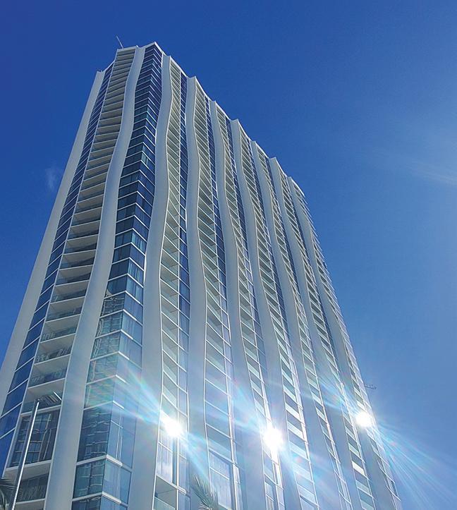
By Steve Baldridge, PE, SE, LEED AP, Anantha Chittur, PE, SE and Mark Hirschi, SE Ko¯`ula is in the center of Ward Village, a 60-acre master-planned community in Honolulu’s urban core that was named
“Master Planned Community of the Year” by The National Association of Home Builders and “Best-Planned Community in the United States” by Architectural Digest. Planned as a beautiful addition adjacent to the community’s central park, Ko¯`ula is a 41-story mixed-use development featuring 942,000 square feet of built area, including a 566unit residential tower, common and amenity spaces, 58,300 square feet of retail space, mechanical and support space, and six stories of above-grade parking.
Columns and Departments
34 Insights

Structural Lightweight Concrete Contributes to Seismic Resistance
By Michael Robinson
36 Structural Analysis
Flexural Design of Reinforced Concrete Beam Sections
By Qian Wang, Ph.D., P.E., LEED AP, and Shahriar Quayyum, Ph.D., P.E.
40 Structural Methods
Code-Checking Concrete Discontinuities
By Lukas Bobek, M.Sc., and Petra Komarkova, M.Sc.
44 Structural Specifications
Non-Metallic Reinforcement for Concrete
By Aparna Deshmukh, Ph.D., William J. Gold, P.E., Gusai H. AlAithan, and Antonio Nanni, P.E.
48 Codes and Standards
FAQ on SEI Standards
By Laura Champion, P.E., F.SEI, F.ASCE and Jennifer Goupil, P.E., F.SEI, M.ASCE
50 Historic Structures
Burlington Bridge, 1868
By Frank Griggs, Jr., Dist. M.ASCE, D.Eng,. P.E., P.L.S.
58 Business Practices
Tips for Hiring Entry-Level Structural Engineers
By Joseph Yamin, P.E.Gold, P.E. F.ACI
3 Advertiser Index
27 Software Guide
52 NCSEA News

54 SEI Update
56 CASE in Point

That 4-letter Word: Safe
By Kevin H. ChamberlainIt is said that if you are risk averse, don’t bother getting out of bed in the morning. The structural engineering profession is no exception, which practitioners know all too well. In fact the Coalition of American Structural Engineers (CASE) was born out of the idea of risk management for structural engineers being an important thing.
Structural engineers are frequently asked by property owners to weigh in on whether their existing building or structure is safe. Sometimes in response to a specific event that has occurred such as a partial collapse or new cracks showing up. Sometimes on behalf of a buyer looking to purchase a building. Sometimes because of a directive or concern from a government authority.
Universally, what the client wants to know in hiring a structural engineer for an assessment is: Is my building safe? Can I continue to use the building. Is this condition dangerous? If a government entity has initiated the inquiry, they want to know whether to allow occupancy to continue or is public safety in jeopardy.

No pressure, of course.
My firm’s practice is primarily design work, but we try to service all our client’s needs, and sometimes those needs include condition assessments. So, we pick and choose which ones we take on while weighing many factors such as fee, workload, client importance, and having enough information (existing drawings) to do our job.
Recently I was asked by a municipal client for a second opinion on a parking deck at the local shopping mall. Parking garages in cold climates are notorious for having short lifespans due to freeze thaw cycles, the corrosive effect of deicing salts, value engineering during construction, and not enough maintenance. Consequently, parking garages are a frequent request for condition assessment. This garage was a poster child. At 35 years of age, it was at the end of its expected service life, and starting to exhibit problems requiring serious repair or replacement. Then one day, the wheel of a pickup truck punched thru the slab, and the municipality ordered the garage closed. The mall hired engineers and contractors to implement temporary make
safe work. Problem solved, right? Not yet. The municipality wanted a second opinion that the make safe work the mall’s engineer specified did what the name implied: Was the garage safe for reopening to people and their vehicles? The municipality has a responsibility to protect public safety. No pressure, but by the way this was right after Thanksgiving during the busy Christmas shopping season!
Shortly afterwards, I got another call from a friend, whose house was hit by a tree. It hit the room they were in while watching football in real time. Talk about scary. We make it a practice to turn away most homeowner calls as they tend to clog our job list. But it’s hard to say no to a friend in a panic. Was his house safe for his young children to sleep in their beds at night? I would hate to make the wrong call on that one (so would he!).
Nationwide, there is an abundance of empty office space due to the pandemic and remote work (and even before that in some regions). Real estate investors call up wanting an assessment of an office building they are considering buying. Is this risky? May not seem so at first blush, but they are studies you’ll often have to do with limited information, limited time, and limited fee. If you miss something and the buyer’s profitable real estate investment turns unprofitable, they will turn to you to recoup their losses. Remember that report you wrote while being harassed by the client to turn it around in a few days saying the building was in good shape? The client won’t remember that they put pressure on you.
The word “safe” is a 4-letter word, like using the word “guarantee” or “highest quality” in one of your engineering contracts. If you do feel you can say something is safe, explain all the caveats that go with it. In the case of the parking deck, I had to explain to the municipality that the make safe work others had implemented was all about managing risks: eliminating the major ones, and mitigating the smaller ones. CASE 962-A: A Guideline Addressing the Preparation of Structural Engineering Reports for Buildings is a good resource
which includes sample disclaimer statements which can go into a structural report. Another consideration in assessing a building: should you include a structural analysis of the existing structural system? It depends on the project - often you can’t render an opinion on a building without crunching numbers. If you feel a structural analysis is warranted, yet the client balks at the scope and fee to do so, consider walking away. Understand that even when the client is amenable, you may not have enough information to analyze the structure, if the original structural drawings are no longer available – information you’ll want to know when writing your proposal. Perhaps the biggest downside risk to conducting a condition assessment for a property owner is that you find real problems with their building and they choose to ignore your recommendations. Or even worse you are limited in discussing your findings due to a non-disclosure agreement. Engineering ethics and legal obligations may be at odds, but paramount is the engineer’s duty to protect public safety above all else.
Ultimately, a structural engineer will need to decide if taking on structural condition assessments are a project type that makes sense for their practice. Some firms prefer to stick to design work, why inherit someone else’s mess (and liability) when design work is more comfortable and controllable. Others choose to pursue building assessments as the main source of their livelihood. They understand and weigh the risks and have the skill and savvy to make those projects profitable and rewarding. These forensic firms don’t mind having to be a mix of private detective/crime scene investigator/fortune teller/mad scientist. In fact, they thrive on it. And the rest of the profession are secretly grateful we have their contact info to pass along to clients!■
Stephanie Slocum structural INFLUENCERS

Stephanie Slocum is the Founder and CEO of Engineers Rising LLC and is a career and business strategist for engineers. She is the author of She Engineers, chair of the Structural Engineering Institute’s (SEI’s) Business Practices Committee and has also been elected to the SEI Board of Governors. (stephanie@engineersrising.com)
How has the pandemic changed the landscape for women engineers? What are the new challenges and opportunities?
The pandemic has changed the way everyone works and has been particularly challenging for those who are caregivers. A 2020 NCSEA SE3 survey of structural engineers found that 87% of women structural engineers with dependents reported providing more than 50% of dependent care, compared to only 42% of male structural engineers with dependents. In that same survey, 57% of women structural engineers reported needing to choose between work and caregiving often or always, compared to 20% of men. More concerning: only 4% of all respondents said that their firms were supportive of employees with dependents. The pandemic has presented a documented challenge for workforce retention of women with dependents. For example, one survey of 5000 professional women published in Forbes magazine found that nearly 80% of women said their workloads have increased because of the pandemic, and 66% reported having more responsibilities at home. This created a perfect storm for burnout and retention challenges for women in work cultures that did not adapt quickly to provide the flexibility and support needed to balance those responsibilities.
Is the “perfect storm” all bad news?
No. That perfect storm has also created an opportunity for nimble organizations that want to improve gender diversity in their leadership pipelines. Women are demanding more from their work. In fact, women leaders in 2021/2022 are leaving their companies at the highest rates on record for better opportunities, better work cultures, and more workplace flexibilities (Source: 2022 Women in the Workforce report). Anecdotally, in the last year, I have worked with an unprecedented number of ambitious, rising female stars who are changing jobs. However, it is not simply moving from one employer to another. Instead, they are taking career risks by pivoting to different industry sectors, taking a career break instead of putting up with an unsupportive work culture, starting businesses, and choosing career options that prioritize schedule flexibility and employee wellness.
You have written and spoken in the past about how women engineers can self-advocate to advance their careers: Has that also changed due to the pandemic?
From a self-advocacy standpoint, the normalization of remote work has enormous benefits for women. According to the 2022 Women in the Workforce report, only 1 in 10 women (and about 2 in 10 men) want to work primarily on-site. When women work remotely, they experience fewer microaggressions and higher levels of psychological safety. In addition, they can spend more energy focused on their technical work (i.e., the reason most became engineers!) for improved happiness and work outcomes. The challenge with limited exposure is to avoid proximity bias (i.e., out of sight, out of mind) in work environments where some
workers are mostly remote while others are primarily in-person. Remote workers must intentionally overcommunicate their ambitions, activities, and accomplishments to maintain visibility if they want to advance in the future.
One final pandemic-related opportunity is the relative ease at which rising female leaders (and anyone with initiative) can obtain 1:1 mentoring from senior leaders – typically men – when requested in a virtual environment. My case study research of women leaders in STEM found that 1:1 mentorship is essential for women’s advancement. In addition, online meetings remove much of the social stigma related to gender dynamics compared to a 1:1 closed-door meeting. Combine this with fewer incidents of traditional networking post-pandemic (think happy hours and golf tournaments), and women have more options available to build relationships on their terms if they choose to do so.
What support systems do women engineers need from their office supervisors, and how has the pandemic (e.g., remote work, remote meetings) changed those needs?
The pandemic has not changed the needs of women (and everyone else). Instead, it has brought clarity, empowerment, and reconsideration of how life and work are intertwined. That means fewer employees tolerate work cultures that do not provide the support they need.
It is also notable that managers – which in some cases ARE the office supervisors – may not be getting the support, training, or resources they need. It is challenging to support your people when you are not supported. That lack of support is a contributing factor to the burnout faced by an estimated 40% of female people managers.
How can we support people better and prevent that burnout?
I recently gave an in-person presentation where I spoke with two employees who had been at their company for 20-30 years. I asked them what made them stay. Their response: “My boss.” That does not happen by accident. Organizations and supervisors need feedback from employees to determine what they can do to create that response and reap the retention benefits that come along with it. Additionally, firms must reward supervisors for supporting employee well-being, advancement, and inclusion within their teams. Too often, this is treated as a nice-to-do (because it’s not a billable hour) when in reality, an individual manager’s actions are directly linked to retention costs.
To gain a better idea of what support systems help most for women specifically, the data from my 2021/2022 Women in STEM case study interviews found that the top 5 strategies for organizations supporting gender equity are: 1) Cultivate belonging, 2) Provide workplace flexibility without stigma, 3)Provide individualized professional development, 3) Make growth and promotion paths transparent, and 5) Fix the pay gap. (Author note: We have provided a link to the full report in the digital version of this article at www.STRUCTRUEmag.org. ) (For the digital version - You can get a copy of that full report HERE.) Notably, none of these items are new, and that research has long shown that ALL employees want these things. What has changed with the pandemic is employee tolerance for organizations that do not meet their needs.
What advice do you have for women engineers who are starting to manage staff? How has the pandemic made new challenges and opportunities for managers?
Women engineers starting to manage staff must put on their oxygen masks first. Practically, this means having an explicit conversation with their managers about how success in their role is defined and what dayto-day activities are essential for work outcomes. New technical managers have a higher statistical likelihood of burnout than other groups because individual contributors are often promoted because of their excellent technical expertise without management training, and successful outcomes in their new roles are not clearly defined. When high-achievers don’t know what activities lead to success, they tend to overcompensate (speaking from experience here!) by taking on extra work that may or may not be tied to role outcomes.
Managing staff is a separate responsibility - not an add-on to technical work – and must be treated as such. As a people manager, getting clear on expectations for yourself also allows you to communicate clear expectations and work outcomes for your staff and empower those you manage to make decisions for themselves on how they achieve those outcomes.
Communication must be a big part of that, yes?
Absolutely. The biggest challenge and opportunity for managers in the pandemic is effective communication and collaboration. A hybrid and remote workforce require intentional communication and collaboration; managers who could get away with unclear emails and directions in person flounder when managing staff remotely (and are typically the first managers to say remote work doesn’t work). On the other hand, this has created significant opportunities for rising stars who excel at communication and are up-to-date on collaboration technologies to accelerate their paths to
leadership. On the flip side, mindful communication can spiral into spending all of your time in email, and virtual meetings, which is why establishing expectations (and setting boundaries) for your role is essential.
I have observed from the pandemic that technology (Zoom, Teams, Facetime, email in general) results in less site visit time for structural engineer designers. What are the pluses and minuses of that trend for women engineers?
Less site time does result in fewer challenges for women in dealing with microaggressions on construction sites related to gender stereotypes. However, with that exception, I see the decrease in site time as a negative for three reasons.

First, for many designers seeing something they have designed being built and connecting with the users of projects (such as might happen at a groundbreaking ceremony) is the single most fulfilling part of the work. It is the thing that keeps them motivated when work deadlines pile up and there are late nights in the office, and a tangible reminder that their work matters. Women are more likely than men to say they went into engineering so they could apply their technical skills to make a difference in the world. Reduced site time is a missed opportunity to connect directly to that sense of purpose. Studies show that purpose is fundamental to individual career fulfillment and employee retention.
Second, effective communication with contractors is essential to career advancement in structural engineering. Learning that skill involves putting in the time and observing a senior engineer doing this well. The sooner structural engineer designers get comfortable being on site, communicating with contractors, and troubleshooting field fixes, the sooner they develop the skillsets necessary to rise into leadership.
Finally, site visits are one of the best places for engineers to deepen relationships and reinforce their technical expertise with contractors and owners. While site conditions can be shared via technology and often give engineers sufficient information to solve field challenges from a data standpoint, there is no good substitute for being on-site with contractors, owners, and potential clients (such as architects). For example, structural engineering designers whose firms facilitate their young engineers’ building relationships with young architects find that these become clients 10-15 years later as both mature in their respective expertise. More site visit time creates a business advantage for the individual and their employer.■
Ko‘ula Inspired by Nature
BY STEVE BALDRIDGE, PE, SE, LEED AP, ANANTHA CHITTUR, PE, SE AND MARK HIRSCHI, SE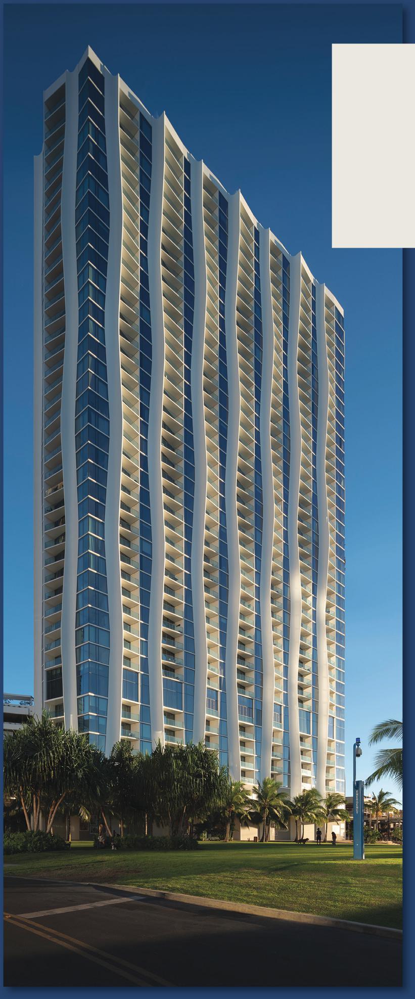
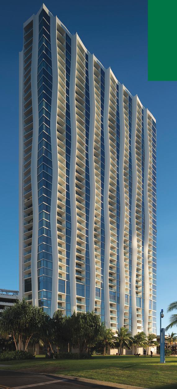
Kō‘ula is in the center of Ward Village, a 60-acre master-planned community in Honolulu’s urban core that was named “Master Planned Community of the Year” by The National Association of Home Builders and “Best-Planned Community in the United States” by Architectural Digest. Planned as a beautiful addition adjacent to the community’s central park, Kō‘ula is a 41-story mixed-use development featuring 942,000 square feet of built area, including a 566-unit residential tower, common and amenity spaces, 58,300 square feet of retail space, mechanical and support space, and six stories of above-grade parking.
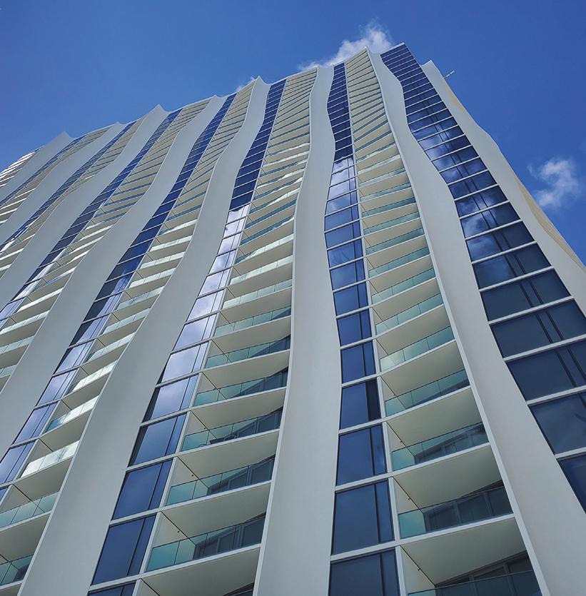
Kō‘ula, in native Hawaiian, means “red sugar cane” and inspired the undulating sculpted structural columns at its exterior façade, evoking the twisting structure of the sugar cane reeds that were formerly grown on plantations nearby. The unique design was created by internationally renowned architecture and urban design practice Studio Gang, led by MacArthur Fellow Jeanne Gang. According to Studio Gang, the building is designed from the inside out to seamlessly connect inhabitants with nature. Like many of the island’s native grasses that stretch toward the sun, the individual residences subtly peel off from the central core and angle themselves toward the coastline to capture views of the Pacific, the city, and the Ko‘olau Range. The columns, which were constructed entirely of reinforced concrete, were designed in collaboration with the engineer of record, BASE, and design-assist contractor, Hawaiian Dredging Construction Company, and were coordinated carefully with the architect to allow for the modularization of formwork and simplification of reinforcement while still providing an organic and unique defining architectural feature for the tower.
Behind the striking exterior, the structure primarily consists of post-tensioned concrete floor plates, reinforced concrete columns and shear walls. In the parking areas, long-span post-tensioned beams and floor slabs utilize a repetitive garage beam forming system to open the floor plan and maximize visibility, ventilation, and the space available for parking stalls. The garage beam system also allows for large column-free areas at the ground level for
building support, mechanical areas, loading docks, and car drop-off for the retail spaces. This long-span system, combined with carefully spaced tower columns, also created relatively large column-free retail spaces that make up almost 50% of the ground floor area.
The tower itself is approximately 225 feet long in the north-south direction and 79 feet wide in the east-west direction. The tower’s lateral system consists of concrete shear walls around the elevators and stair cores to resist Honolulu’s hurricane-level winds and moderate seismic demands. Projects often utilize coupling beams made as deep as possible while maintaining minimum corridor height to connect the shear walls across corridors and limit building drift. However, due to the orientation and location of the tower’s shear walls as well as the limited floor-to-floor height provided, innovative shallow plate-reinforced composite link beams were implemented. In lieu of providing openings through the link beams, some beam depths were instead decreased further to allow mechanical and plumbing services to run under the coupling beam, reducing coordination efforts and minimizing or eliminating the chances for conflicts and clashes to arise between the structural, mechanical, and plumbing trades during construction.

Structure Supporting and Enhancing Space Planning
Maximizing the ocean views, ideally for all units, is one of the most significant design requirements for residential high-rise developments in the Ward Village neighborhood. In addition, development restrictions mandate that towers be oriented perpendicular to the ocean to avoid blocking view corridors to the ocean from the mountains and other buildings behind Ward Village. To overcome this requirement and provide all units with an ocean view, the architect laid out residential units with a portion of each unit protruding at an angle from the primary building mass with a broad face along its perimeter angled towards the
ocean, referred to as a “podular” layout. The exterior columns, slab edge, and balconies are oriented in such a manner that each unit has both ocean views and privacy from their neighboring unit.

To create a welcoming drop-off area for residents, a full-height transfer girder is provided at Level 3 to increase space between columns at Level 2 and create room for a vehicular turnaround. This transfer girder is architecturally integrated as a backdrop to the adjacent open walkway connecting the tower and the adjoining mid-rise residential portion of the building and is ornamented with architectural screening and accent lighting.
At Level 2, a new exterior courtyard was created with a view to interconnect the retail vehicular drop-off, tower entry, and access to the adjacent park to create a civic hub. This courtyard consists of a cantilevered walkway at Level 2 that connects the retail in the mid-rise building on the north side with the retail on the tower’s second floor overlooking the public park. Post-tensioning was essential in creating large terraces for gatherings and circulation that cantilever almost 15 feet from the supporting columns. An exposed concrete staircase within a large, organically-shaped oculus provides connectivity between Levels 1 and 2. This 45-foot-long staircase consists of a central conventionally-reinforced concrete spine beam with thin treads cantilevered to either side of the beam.
The exterior architectural columns continue uninterrupted from the foundation to the roof on three sides of the building, but on the east side, the tower façade is set over portions of the parking garage. This overlap requires columns on the east elevation to be terminated at Level 8, reshaped into rectangular columns, and rotated to provide adequate clearance for parking stalls. Most of these transitions are made with direct bearing on overlapping areas of columns below with additional compression dowels provided as required. Shallow beams are provided at more extreme transitions to transfer the overhanging
column to its supports below.
It was a challenge to fit the planned 41 stories within Honolulu’s strict 400-foot height limit. To create a minimum ceiling height of 8’-8” within the typical residential units and considering construction tolerances, the slab depth was restricted to only 7” thick. Unit layouts dictated spans of around 26 feet at the building perimeter, with some localized interior spans of up to 34 feet. The only way to keep deflections at reasonable levels to accommodate architectural floor finish requirements was with post-tensioning. BASE built three-dimensional analysis models of the floors utilizing RAM Concept and went through several iterations of finessing posttension forces and drapes to optimize the floor for both strength and serviceability requirements.
Expressive Structure as Architecture
The most distinctive features of the building are the beautifully sculpted exterior columns made possible only through extensive collaboration between the architect, structural engineer, and design-assist contractor. Several meetings were convened early in the design process to evaluate an efficient and economical
design for the 400-foot-tall columns while still providing an iconic shape for the exterior of the tower that forms an intimate connection to its surroundings.
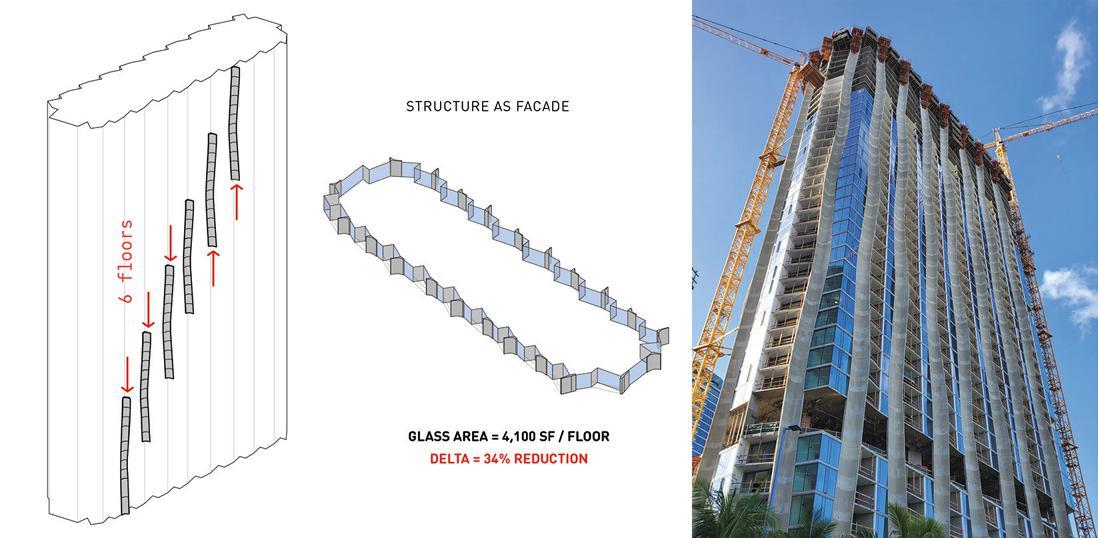
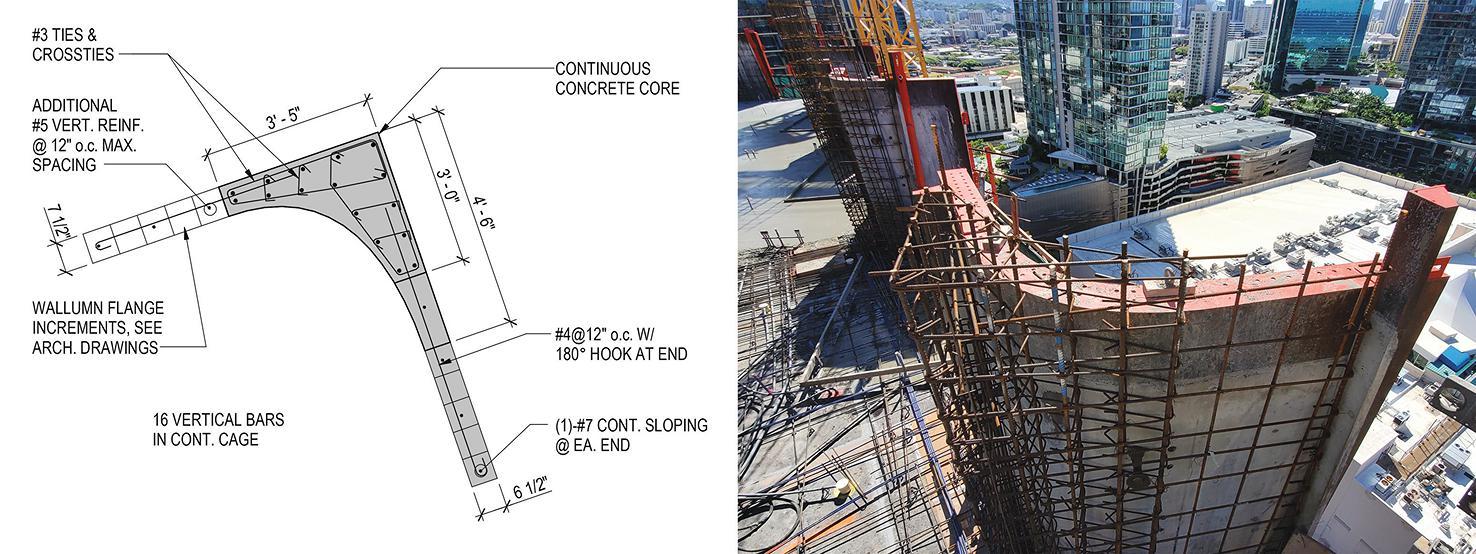
The resulting exterior columns stretch in and out, undulating back and forth as they progress vertically along the façade like the swaying red sugar cane their form was based on. The key to the expressive columns’ structural performance is a central core or stem within the shape where most of the load would be carried. Thinner concrete segments project from that stem, which swell and ebb in unison to provide the columns’ dynamic form. After many studies, the design team arrived at a single central core of constant area and shape at each column that extends through the entire height of the building capable of carrying the tower’s structural loads. This uniform shape allowed for easy lapping/coupling of reinforcement, consistent dimensions for tie and cross-tie fabrication, and a single shape for ease of forming.
Although, the formwork costs incurred for these columns were higher than conventional columns, the efficiency and simplicity of the concept allowed for easy modularization. The architect produced several sketches and isometrics illustrating the cycling of formwork around the tower footprint, and these depictions reinforced and helped communicate the efficiency of the system so it could be accurately captured by estimators. As a result, pricing exercises revealed that the final column forms resulted in cost savings for the project, both in reduction of initial construction cost as the expressed column concept replaced areas of expensive curtain wall glazing and in long-term operational costs due to reduced energy requirements from lower solar heat gain to the units due to the concrete perimeter enclosure.
Construction Challenges
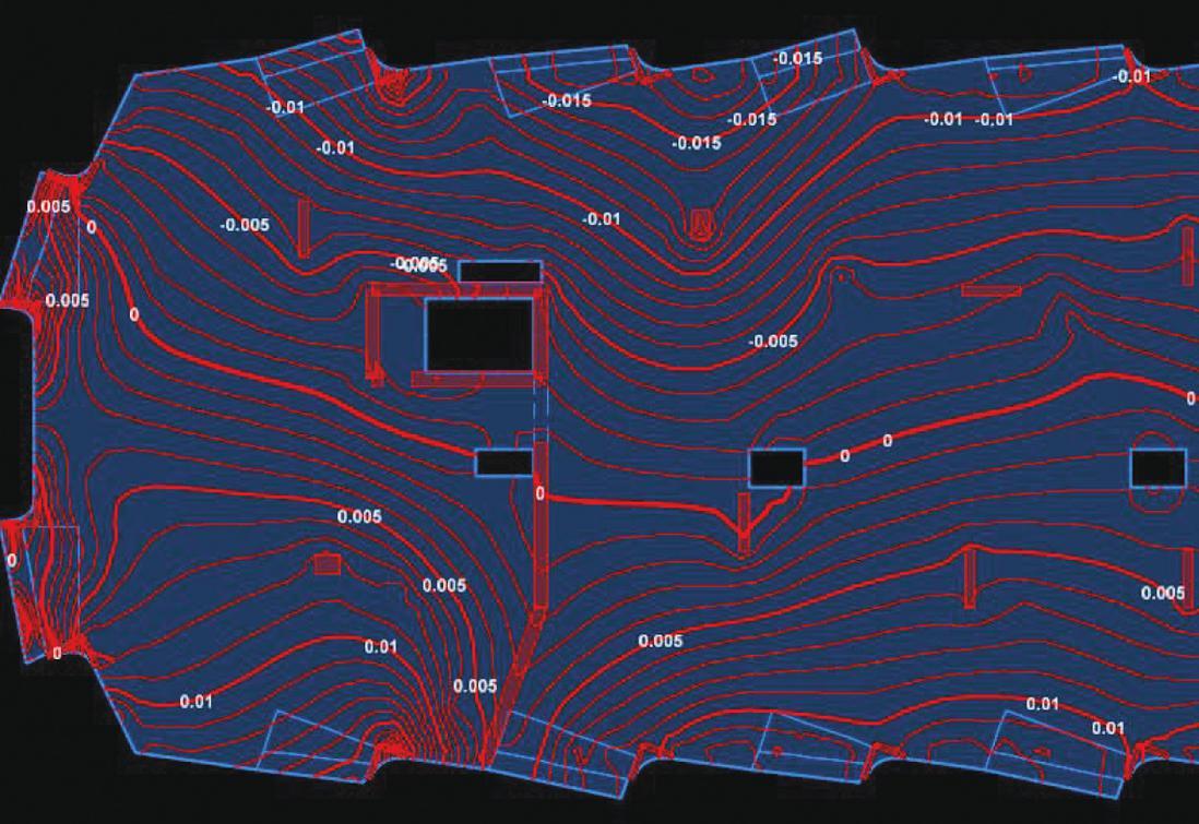
Determining whether post-tensioning would result in any unsightly shortening of the slab was a unique construction question that needed to be answered. With the prominent architectural columns exposed at the perimeter, movement of these columns inward could produce an unintended alteration to the aesthetics of the carefully sculpted concrete façade. The design and construction team considered many options, including pour strips in two directions and slip joints at the columns. But these options would slow construction and be difficult to execute in the field. In lieu of more intrusive modifications, floor designs were instead further studied and optimized to provide the least post-tensioning required for strength and serviceability to reduce the potential for shortening. While typically not done, the structural engineer developed detailed finite element analysis models to determine movement estimates based on both shortening due to post-tensioning and shrinkage due to curing of the concrete. These estimates were provided to the contractor for their planning of the tower and architectural column construction. While the custom steel forms chosen for the exterior columns helped create a clean and consistent finish, they prevented the post-tensioning stress pockets from being placed in their normal locations within the columns. Even if there was a way to cut holes in the forms for these pockets, the grout plugs could create some visual discontinuities in the otherwise uniform face of the architectural columns. The rhythm of the exterior columns’ undulating shape meant that the column was at its widest at the slab edge on one side of the building while being at its narrowest at the slab edge on the opposite side. The team took advantage of this feature by anchoring the tendon dead ends on the wider end and locating the tendon live ends to be stressed outside the column footprint on the narrower end. At floor levels where this solution was not feasible due to the column having uniform projecting legs, the structural engineer and contractor coordinated locations for stressing tendons within existing slab openings or provided stressing blockouts. Where tendons were unable to pass through the column core, conventional rebar was lapped with tendons and anchored within the supporting column to satisfy code requirements.
Completion
Planning was a big part of executing the undulating concrete façade. The undulating columns had to be integrated with the exterior window wall, the balcony slab edges, balcony glass railing, and unit interior layouts. Prior to construction, the architect, structural engineer, and contractor developed a full-scale mockup of the exterior column, including vertical and slab reinforcement. This mockup was constructed to help identify constructability issues, evaluate mix designs, confirm the achievement of the desired architectural finish, troubleshoot glazing installation against the sloped column edge, and assess the visual impact of the proposed reveal locations, sizes, and depths. The tower floor plate and each unique column geometry repeats itself every 12 floors, despite appearing random. In addition to the structural concrete façade, over 4,000 window wall panels, including sliding glass doors, of which there are 365 unique sizes, combined with 2,278 balcony glass panels in 111 unique sizes, complete the unique and beautiful exterior of the building.
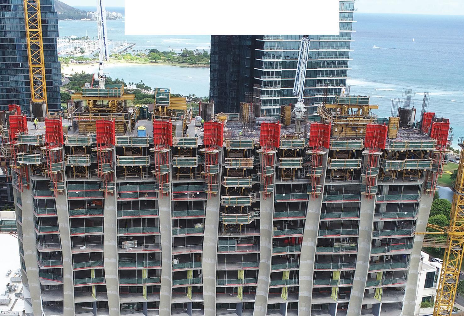
The concrete forming for the tower slabs includes approximately 50 truss flyers and a variety of infill panels, beams and band slab forms for the podium and parking levels. The formwork for the expressed columns includes 22 custom fabricated steel forms featuring multilevel strongbacks to assist with lifting and vertical alignment of the overall system. In all, over 39,000 cubic yards of concrete was poured for the structure’s deep foundations, the architecturally exposed concrete, the structural frame, and a variety of landscaping and pool structures including an extensive concrete planter system helping to beautify two sides of the podium parking levels with a vertical green wall. The structure was reinforced with 6,700,000 pounds of reinforcing steel, both standard strength and high strength where beneficial to reduce quantities and minimize rebar congestion in the higher loaded lowerlevel columns, concrete columns, and shearwalls. Post-tensioning included 760,000 pounds of 270 ksi unbonded strands, or 0.80 pounds per square foot.
BASE also served as the project’s “Structural Special Inspector” and concrete testing laboratory, logging more than 4,000 hours on the jobsite throughout construction. Construction related services were also provided, including reshoring review, tower crane and man hoist foundations, slab blockouts for concrete pumping. Being involved in these services was found to be beneficial in keeping the project running when questions would arise in the field.
Conclusion
The construction was started in October 2019, just a few months prior to the once-in-a-century worldwide pandemic. With construction considered essential, work was allowed to proceed with a variety of
precautions put in place by the contractor. Despite those precautions, work was stopped a few times during construction out of caution for workers’ health and safety. Other challenges included raw material shortages, supply chain issues, and the uncertainty of global logistics. Regardless of these unique challenges, the contractor worked with the owner, design team and trade partners to meet the project’s occupancy date. The tower was topped off within 24 months, in October 2021, and residents started moving in in September 2022.
Despite numerous challenges, the final structure proved to be a success, supporting and expressing the architect’s vision. Additionally, the expressed structure resulted in both economic and environmental benefits, decreasing the amount of glazing required and helping to insulate the tower against the Honolulu sun, reducing air conditioning energy requirements over the life of the building. The result is an iconic structure to serve as a hub for Ward Village’s residents and prominently anchor the development’s central park.■
Steve Baldridge, PE, SE, LEED AP is a principal at BASE and can be reached at (sb@baseengr.com).
Anantha Chittur, PE, SE is a senior associate at BASE and can be reached at (achittur@baseengr.com).
Mark Hirschi, SE is an associate at BASE and can be reached at (mhirschi@baseengr.com).
Project Team
Structural Engineer of Record: BASE
Owner: The Howard Hughes Corporation
Architect of Record: Studio Gang
General Contractor: Hawaiian Dredging Construction Company
A Steel Joist Is A Beautiful Thing.
Why Not Treat It Right?
- Steel Joist Institute
Treating a steel joist right requires loading joists in accordance with their design criteria. Loads must be applied to both chord angles without creating a torsional moment. With that fact in mind, Chicago Clamp Company has designed and tested their Tube Framing Clamp System.
Load applied through the center line of the top chord
Chicago Clamp is uniquely designed to load joists concentrically
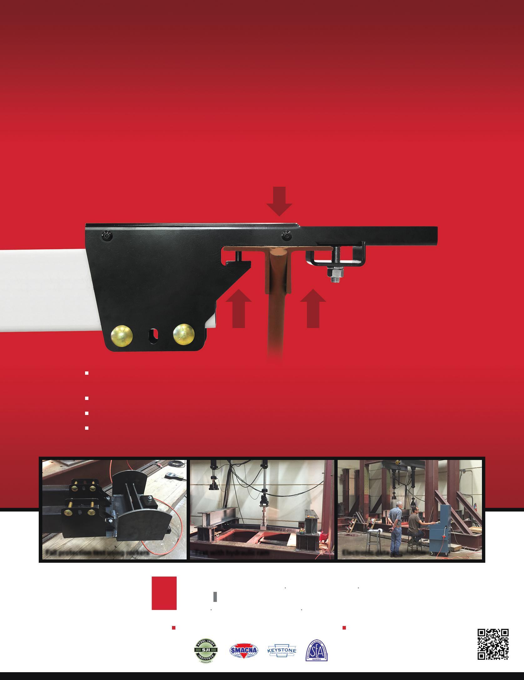
Load applied symmetrically during uplift
The clamp’s strength and stiffness transfer the load vertically to the center of the joist’s top chord in download and transfer symmetrically during uplift
Testing was performed using rocker end-attachments to avoid reliance on torsional strength of the joist chord
Clamping to joists avoids possible detrimental effects of welding to joists that are under stress due to loading
Clamping has the economic benefits of reducing labor costs, reducing installation mistakes, and reducing job delays (associated with locating and sizing curbs and openings prior to steel joist installation)
Phone: 708.343.8311 Email: info@chicagoclampcompany.com
Location: Broadview, IL
“The design of open web steel joists is based on concentric loading. Asymmetrical loading can reduce joist strength ”
The Unfinished Bridge
Othmar Ammann's George Washington Bridge, NYC
By Alice Oviatt-Lawrence, AM ASCE, GCThe many 19th century engineering design-proposals to span the Hudson River between New York City and New Jersey reveal a progressive shift from heavy rail-bridge designs to lighter bridges, as the era burst into the vehicle age in the 1920s. Before then, ferries and car floats transferred freight, horse-drawn carriages, goods, and a few “horseless carriages” across the Hudson River to and from Manhattan, to connect with various rail companies to complete the land transport. With suburban development, combined with the popularity of the automobile, a public outcry developed for the expansion of roads and bridges.
To meet such demands, the Port of New York Authority (PNYA), established in 1921, acted quickly to organize a bridge division to design many new bridge projects. One project was
Othmar Ammann's (1879-1965) 1924 bridge design for an uptown steel “Hudson River Suspension Bridge” at 179th Street, to connect New York City to Fort Lee in New Jersey, later known as the George Washington Bridge. The U.S. War Department approved the design for a center-span of about 3500 feet suspended between two tower piers set close to each shoreline, a 4760-foot long span between anchorages, and a deck elevation of 235 feet above mean high water (MHW). The main span was over twice the length of any previous suspension bridge, and the number of traffic lanes even today surpasses any other suspension bridge in the world.
Thorough traffic-count studies to justify the need for a bridge in the 1920s accurately predicted an annual bridge usage of eight million vehicles by the 1931 opening, but this largest
bridge-building undertaking in history was effectively designed for a capacity of over 50 million, reached in 1960. Today's actual annual traffic count is about 110 million.
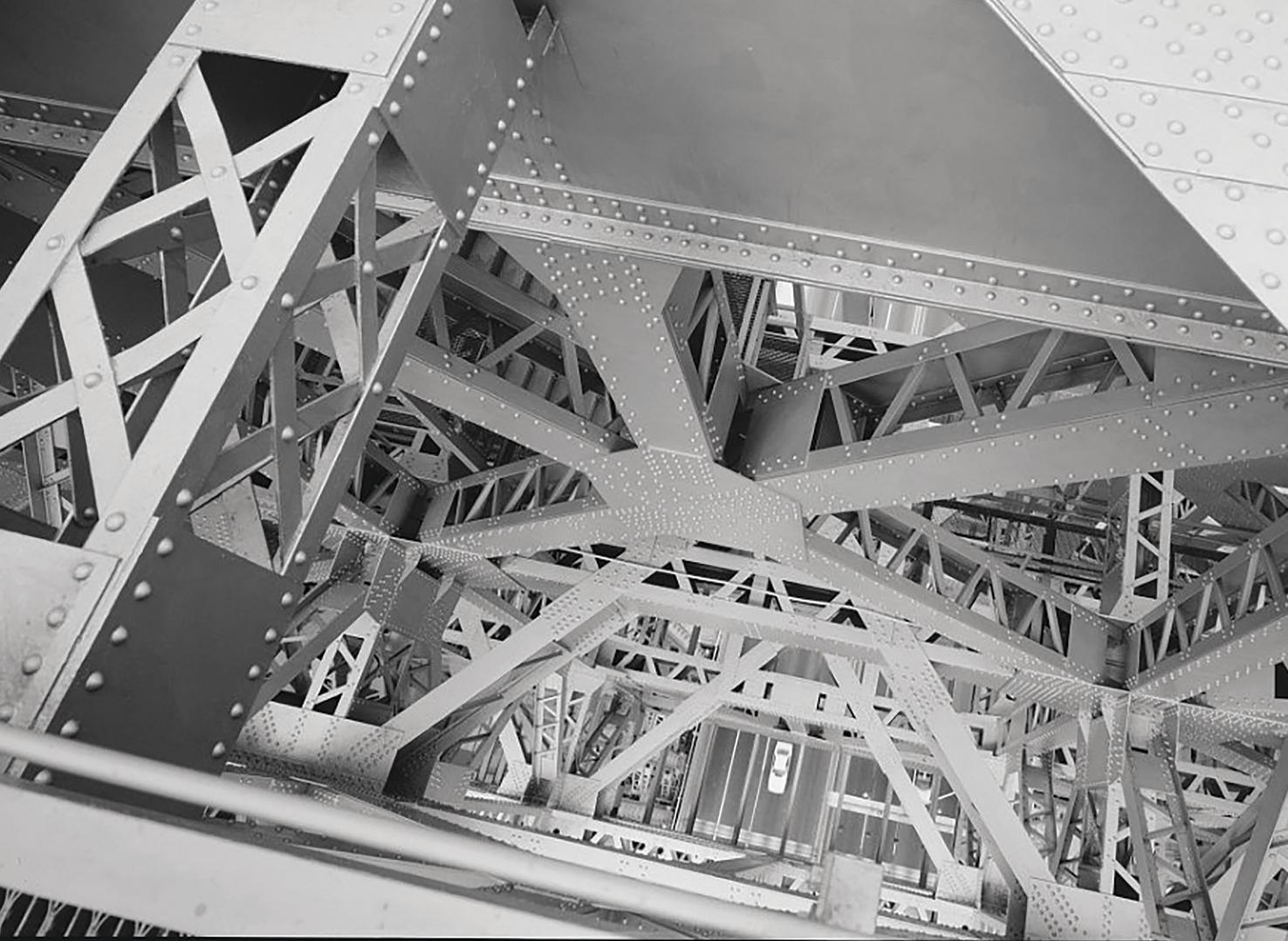
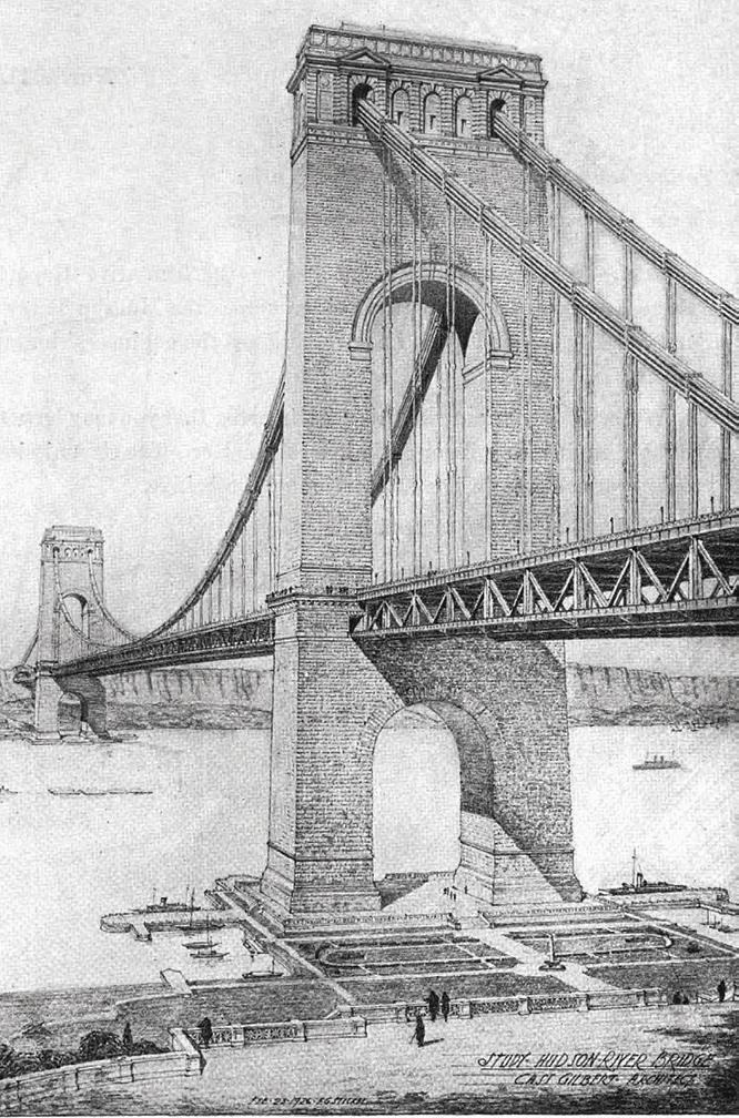
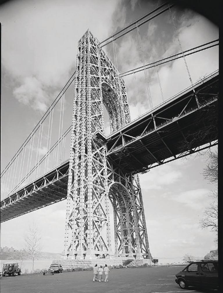
The original design intention for the George Washington Bridge consisted of four huge masonry-covered steel space-frame towers, the tops of which soar over 630-feet high above MHW. Original plans included a reinforced concrete encasement, with or without a granite facing, to be constructed over the monumental steel-skeleton towers. Drawings show a masonry bridge with an arched portal above and below the deck, and a thin, modern-appearing deck. But when the bridge opened in 1931, it was without the masonry encasement, and without a planned observation deck and restaurant at the tops of the towers.
The New Jersey and New York legislatures amicably established legal and financial support for the bridge. The $55 million-dollar projected construction cost - with the highest cost attributed to real estate - came in under budget and the bridge opened before the projected opening date. Tolls readily paid back all debt, as the area population nearly doubled in the 1920s. The bridge today is owned and operated by the Port Authority of New York and New Jersey (PANYNJ).
Background & Theory
Othmar Ammann first studied architecture in his native Zurich
before switching to engineering studies at the Swiss Federal Institute of Technology, graduating in 1902. He then immigrated to New York in 1904. Wilhelm Ritter (1847-1940) was one of Ammann's professors: From him, Ammann learned to physically test models, and, at the same time, compare test findings with that era's early scientific calculations to predict general structural behavior. Ritter understood and taught French engineer Claude L.M. Navier’s (1785-1836) 1823 observation that the greater the dead weight and length of a suspended span, the lesser the need for the standard, heavy allowances in deck stiffness. With these thoughts in mind, Ammann designed a deck vertical height-to-span ratio of 1/350 for the bridge, rather than the standard-to-date ratio of 1/60 for shorter long-span suspension bridges. The extreme ratio worked due to the superstructure’s great weight and length stiffening effect. Ritter also emphasized aesthetics and Ammann shared that aspiration, leading him to seek a masonry exterior to the towers.
Tower Foundations
The tower foundation rests on solid Manhattan schist near the New York shore. The New Jersey foundations rest on sandstone 70 feet from the shore. Soil boring cores taken at the tower bases tested at 12,000-15,000 pounds per square inch (psi) average compressive strength, about 30 times the expected maximum tower-base pressure.
Anchorages
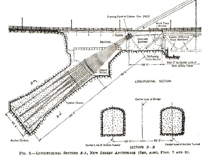
On the New York side, a gigantic structure, weighing 350,000 tons, required 110,000 cubic yards of concrete to anchor the bridge. Each main cable, of 26,474 galvanized five-millimeter diameter wires, splays into 61 strands of 434 wires connecting to eye-bar anchor chains and girders embedded in concrete to a 113-foot depth.
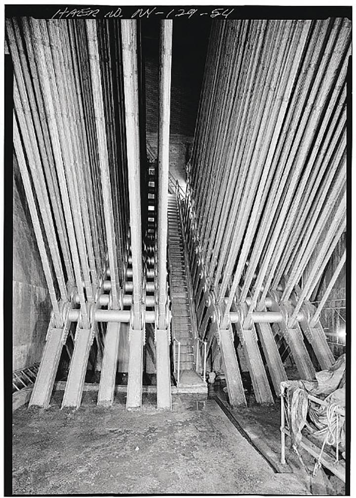
In New Jersey, tunnels were blasted into the trap-rock Palisades cliff to about a 150-foot depth to anchor the cables, with voids filled with reinforced concrete. Ammann, while working for bridge engineer Ralph Modjeski in 1905, acquired expertise in developing reinforced concrete technology, unlike many of his contemporaries.
Towers
Leon S. Moisseiff (1872-1943), Advisor of Engineering Design for the project at the PNYA, designed each tower as four steel rigidly connected bents forming space frames, ascending to their great heights above MHW. The inner columns are vertical while the outer columns are battered 3/16 inch to the tower top. The enormous tower dimensions at the deck are 75 by 215 feet and taper to about 50 by 180 feet at the top. The chemical composition of the heavy 41,100-ton structural steel skeleton
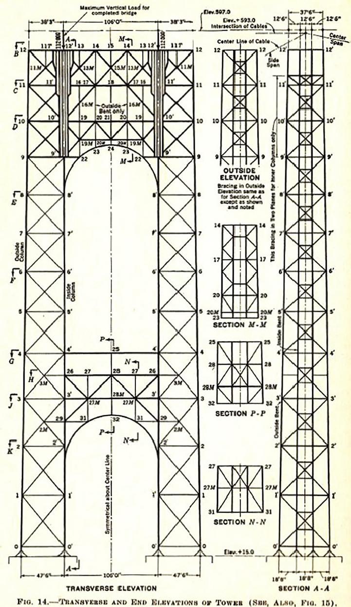
towers is 23,600 tons silicon steel and 17,500 tons carbon steel. The silicon alloy improves yield strength, elastic limit and fatigue strength.
The inner columns take the entire superstructure load, which is distributed via the diagonal truss members to the outer columns of the space frame. This load increases to a maximum at the deck and follows the load path to the ground.
The assumed future vehicular load of 45,500 load of pounds per linear foot for the planned 1960s lower level – conceived in Ammann's original design –was included in Moisseiff's original design calculations as well; at the same time, Moisseiff strengthened the connections for capacity to include the intended masonry covering.
Not completely trusting the new Deflection Method, Moisseiff performed stress-strain tests on a large model during different stages of construction on the indeterminate towers under various loadings to confirm the mathematical analyses. The main tower members were tested to failure in the model. As Navier had applied his own new simple formulas for forces in the elastic range to studies he had made on a structure, Moisseiff
also carefully measured the physical behavior to compare with his calculations. A large on-site laboratory continuously tested all materials going into the bridge.
Steel Cables
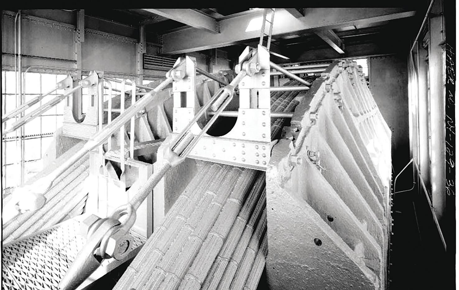
The steel galvanized wire (maximum 0.85% carbon, E=28 x 106) with an ultimate strength of 230,000 psi) was three times stronger than any wire previously used. The thirty-six-inch diameter parallel-wire main cables each contained 26,474 wires, with a total wire weight of 28,300 tons, and an average of 21 percent air voids, compressed. Parallel wire can be compressed 40 percent more than twisted wire. Tensile strength for wire for the project tested at 82,000 psi, ten percent higher than previously manufactured.
Wires of cold-drawn galvanized steel were placed in position on the bridge, assembled, compressed, wrapped, and sealed with lead wool. Then, the resulting cables were covered in thick red lead paste and painted with two coats of aluminum in the traditional method of the nineteenth to early twentieth century suspension bridge cable making. However, by the 1920s the larger open-hearth steel billets and improved wire drawing technologies permitted the manufacture of greater wire lengths, quality, and dimensional consistency.
J.A. Roebling & Co manufactured the wire and, after wire drawing, experimented with stretching the wires in their plant yard. They thereby studied and furthered the technology of pre-tensioning, which advanced the idea of wire tendons for pre-stressing concrete, employed for example in 1950s highway
concrete bridge construction.
Engineers of the era, including Ammann, did not fully grasp theoretical aeronautics. The great dead load of the original superstructure restrained the loaded cable-deformation adequately, itself stiffening the bridge until the 1960s lower deck construction. The original structure allowed for deflections of five feet laterally and ten feet vertically at the center of the main span, under live load and high temperature. [Walking the bridge deck in 35 mile per hour winds at 45 degrees on a partly cloudy spring 2022 day, the author noted marked vibration, vertical undulations and perceptible lateral motion.]
Post-Construction (Ongoing)
The bridge was still unfinished in its 1931 opening. Although wind diagonals were not originally planned for the lower deck designs of the 1920s, the added $182 million-dollar lower deck project in the 1960s included wind diagonals in plane with the bottom chord, similar to the top deck underfloor lateral system. The lower deck addition required adjusting the tower tops several inches shore-ward to resist the forces of the added deck weight and to reduce the top eccentricity of the cable saddles: The saddles originally were not aligned to the tower center lines, creating a slight eccentricity of load which needed to be corrected.
The PNYA developed a clandestine proprietary in-house prototype “digital computer” program for the lower deck analysis and computation, run on the 1950s-era refrigerator-sized computers. This technology saved personnel many thousands of calculating
hours, and foretold the current digital age. Inspections in 1997 revealed corrosion due to moisture of 440 wires of cold-drawn galvanized steel in three of sixty-one strands in Cable B at the New York anchorage. An innovative tie-back and clamp mechanism was employed by the New York office of the PANYNJ to restrain each strand's loading of 400 tons while maintaining equilibrium of the element so that the new wires could be installed. The entire procedure was monitored by strain gauges and displacement transducers. Ongoing rehabilitation includes upper deck finger expansion
joint repairs, deck panel replacements at the towers, and main span paving. Work on the lower deck involves structural steel rehabilitation at the underfloor, lead paint removal and repainting, and replacement of maintenance platforms. The anchorage cable rehabilitation is complete, along with most suspender rope replacement. A significant part of ongoing work involves rehabilitation of the main cables, including installation of a dehumidification system. Sensors scattered throughout the cable air voids will also detect and monitor vibrations, displacements, moisture, temperature, location, and sound, the information from which will be collected into a structural health monitoring (SHM) database, allowing immediate inspection, evaluation, and repair. Temperature and corrosion are linearly related, and sound data can pinpoint areas of broken corroded wires. This “Unfinished” bridge – opening in 1931 without its originally planned masonry encasement of the towers or its intended observation deck and restaurant at the tower tops – stands as it is today as the result of the automobile, a 1929 economic crash, advancements in the strength of materials, and the force of public opinion as to whether an exposed-steel skeleton qualified as an acceptable aesthetic.■
Full references are included in the online version of the article at STRUCTUREmag.org

BUILD LONG LASTING STRUCTURES WITH POWER PRESERVED GLULAM®
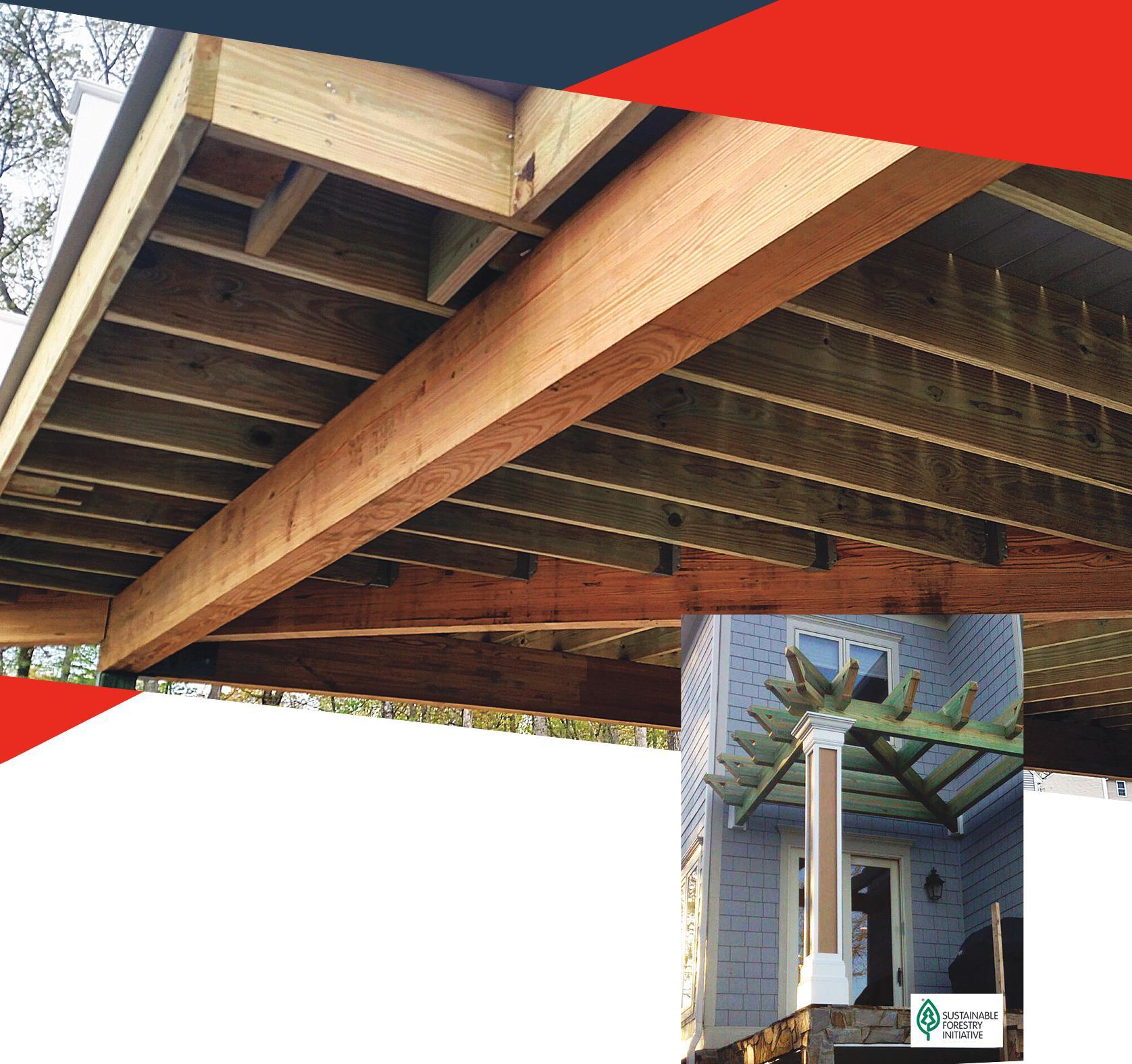
STRONG, DURABLE, SUSTAINABLE
POWER PRESERVED GLULAM® FEATURES
• Manufactured with superior strength southern yellow pine MSR Lumber.
• Offered in two oil-borne preservative treatments: Clear-Guard™ and Cop-Guard® .
• Fast, easy, one-piece installation that’s more efficient than bolting or nailing multi-ply dimension or structural composite lumber members together.
• Excellent choice for decks, boardwalks, pergolas, covered porches and demanding environments such as bridges, highway sound barriers, railroad cross ties, and floating docks.
• 25-year warranty from the treater.

Steering Clear Of Trouble
Keeping on Top of Deliverables and Change
by Stephen F. Willig, Donovan Hatem LLP“
Do what you are supposed to do when you are supposed to do it.” The mantra sounds so simple, obvious, and nearly insulting to preach to professionals. Yet, as we all know, the demands and uncertainties in many projects leave grey areas as to who is responsible and what is the reasonable period to act.
Communication among project participants is key to successfully navigating any project to completion. Nearly every construction dispute the author has dealt with is a version of, “I asked AB to perform X by way of email/oral request for information/change order, and the response did not come at all/was late/was inadequate/or was in the form of ‘not my responsibility.’”
A communication gap allows ambiguity to creep in. The consequences of having expectations that differ from your upstream or downstream partners could be increased cost to correct issues and negatively impacted opportunities for future work.
Common themes emerge from those litigations in which design professionals may become embroiled, from which we can detect scenarios that are potential dispute initiators. Here, the author discusses common problem areas and suggests strategies for minimizing or avoiding prolonged and expensive disputes.
Requests for Information (RFIs)
One fertile area for disputes is in the RFI process. A Navigant Construction Forum Report from 2013, Impact & Control of RFIs on Construction Projects (April 2013), notes that in a review of 1,300 major projects, there were an average of 796 RFIs per project with median response times of 9.7 days and an average cost of $1,080. Thus, they consume substantial amounts of time and elevate costs .
As we all know, an RFI is a request seeking clarification of plans, drawings, specifications, agreements, and other matters. By their very nature, RFIs often arise when something is unclear, when additional information is needed, or when there is a need for change due to problems or modifications. The very fact that they are needed makes the circumstances susceptible to disputes.
Not only are they subject to dispute, but they are also subject to abuse. For example, a contractor may use an RFI instead of regular project communication to build a paper trail supporting a claim that others delayed the work to seek additional time in a construction schedule or additional payments. What better excuse for delay or need for additional compensation than the engineer did not respond timely/adequately/or at all to the contractor’s request?
“It is now common to see contractors submitting an unprecedented number of RFIs and then presenting unauthorized change orders which they claim are the result of the design professional’s response to RFIs. The RFI process provides a methodology for the contractor to document a deficiency in the contract documents and, at the same time, establishes a basis for an increase in the contract amount and/or time.” (Navigant, Impact & Control of RFIs on Construction Projects)
How to avoid abuse and confusions in the RFI process ?
There is no magic pill to guarantee the avoidance of disputes or abuse in the RFI process, but there are approaches to help minimize problems.
• Have a clearly defined contractual process for RFIs. This includes when RFIs are to be used and how you are compensated for responding to improper RFIs or RFIs resulting from unforeseen circumstances or owner changes, as well as the acceptable timetable for responding. The more precisely the process is defined, the less it is open for interpretation or ambiguity.
• Be sure proper and sufficient personnel are assigned to accept and respond to RFIs. If the proper resources are not assigned to the task, no amount of precision in defining the process helps fulfill one’s obligations.
• The best way to avoid problems with RFIs is to minimize their use. Maintain effective and regular communication with project partners to minimize confusion and misunderstanding and, when possible, offer appropriate input on selecting qualified contractors. An experienced and well-qualified contractor should have less need for RFIs or will be more adept at making the inquiries focused.
• Ensure your own work is properly vetted before submission in compliance with your company’s Quality Control procedures and Quality Assurance processes. This includes anticipating what problems may arise based on your prior experience—finding the ambiguities and conflicts before the contractor saves the project time and expense.
• If the RFI raises a legitimate deficiency, resolve it. Ignoring a problem or looking for others to step in only worsens the outcome.
Fulfilling Deliverables
It is critical in any project to have detailed criteria for design deliverables. Not only must the timetable be set, but the level of completeness must be specified. For example, to what level must BIM modeling be developed, are the drawings ready for construction, or is the level of development less? Who is responsible for design coordination?
Failure to adequately define these obligations is a common cause of upstream and downstream problems. Contractors cannot build unless they receive the proper guidance, resulting in delays and cost overruns.
The strategies discussed above apply equally here: define the obligations as to scope and time, ensure adequate resources are assigned to complete the task, and meet the problems head-on with a resolution if it is within your scope. If not within your scope, offer a solution to the owner or project manager. This demonstrates your commitment to the project, showcases your abilities to adapt, and provides an opportunity for further compensation.
Managing Risk Through Contingencies
Cost overruns are real risks to construction projects. Indeed, some cost overrun is found acceptable to ownership. As cited in the McGraw Hill Construction Smart Market Report, Managing Uncertainty and Expectations in Building Design and Construction 2014:
•40% of owners find 1-2% of cost excess acceptable
•38% of owners find 3-5% of cost excess acceptable
•15% of owners find 6-10% of cost excess acceptable
Although there may be tolerance to cost overruns by some owners, no owner wants their project to go over budget. Thus, it is good practice for project budgets to have built in cost contingencies. This aligns the budget with the actual cost of the project and helps avoid negative impact to the owner’s finances. Similarly, some delay may be built into a project as a contingency in the form of schedule float. The key here is mainting the critical path. The float will allow for some disruption in scheduling without impacting following tasks in order to allow for timely project completion.
The issue often is who owns the float, the project, or the owner. The float may be specifically covered in project documents or left to interpretation, but it acknowledges that there is some room for variance with a schedule.
Most understand that projects can exceed budget and schedule to some degree. Of course, all project participants should work toward on time and on budget completion in order to avoid the need to apply contingencies. If that is not possible, acting collaboratively to minimize these risks with full knowledge of the allowable contingencies as well as ownership’s expectations beyond contingencies will help the design professional work within those limitations and avoid disputes.
Top Causes Of Uncertainty
Whether it be the RFI process, project deliverables, delays, or cost overruns, there are recurring circumstances in projects that cause confusion and uncertainty. Unfortunately, only some of these are within the designer’s control.
• Unforeseen Site or Construction Issues by their very nature, are problems that could not be planned for. Was the preconstruction testing, which met all standards, incapable of predicting subsurface conditions through the project site? Could it have been foreseen that certain equipment or material would not be available three years into a project during an unprecedented global pandemic?
•Design Errors
• Design errors or Omissions delay the work, require further design to correct errors, and may even require demolition and reconstruction.
• Inadequate, incomplete, or confusing design or lack of coordination on the design level – if a contractor can’t work from the design or there is a design conflict, delay, and added cost result.
• Contractor caused delays – similarly, the contractor may err in their work, deny responsibility for certain aspects of the work, or not devote sufficient assets to it.
•Owner-driven changes – as is often the case, the owner may decide to make changes as it sees the project unfold; any change requires new design, material requirements, and labor.
•Construction coordination issues – failure to have the proper pieces in the proper sequence translates into delay and
additional cost.
•Lack of owner leadership and clear direction – a disengaged owner who lacks focus on the project or is inconsistent in approach breeds confusion and inefficiency. Direction from the top is important.
Be Realistic And Accept The Circumstances Of All Project Participants
Imperfection is Inevitable. Flawless execution of all aspects of a project is not realistic. Everyone knows this, but when real or feigned issues arise, perfect execution is said to be what was expected. Owners often report to internal stakeholders, including boards and shareholders (or constituents on public projects). In addition, they are subject to external forces beyond their control (pandemics, changing market conditions, and regulations). Thus, their interests may evolve throughout a project, and competing forces may influence their decisions. These impact budget and project changes, and the design professional should understand these sometimes competing forces. Being realistic includes relying on experience. Anticipate problems based on that experience. Even with the best efforts, problems arise. Project participants appreciate being notified that an issue may arise. Suppose the design professional has anticipated a problem and has a process to manage and resolve the problem efficiently. In that case, project interruption is minimized, and the design professional’s nimbleness and foresight are positively displayed.
Communication, Communication, Communication
The author believes communication and collaboration are key to any successful endeavor. Working with all participants toward resolving a problem should be the first response. If all are aware, through effective communication, of their responsibilities and the problem at hand, chances of reaching a collaborative result are greater. Open and regular communications build trust and help avoid finger-pointing. This is also essential in building relationships from project to project. Design professionals, or any party, should not abandon their interests in favor of compromise, but a collaboration strategy toward a favorable result may be in one’s best interests. Maintaining regular communication also affirms awareness of one’s responsibilities and limits.
How is this accomplished? It can be as simple as promptly responding to calls and emails. Face-to-face communication presents an opportunity to demonstrate the ability, knowledge, and willingness to talk through issues. RFIs should be responded to promptly, completely, and clearly.
What Can Happen When Things Go Wrong
It is hard to provide details of what may happen through litigation, as most resolved cases carry some confidentiality obligations, and attorneys are reluctant to share details on a client’s matter (nor do design professionals want details of disputes publicized). However, common across the board in litigation is the fact that the process is bad for the business of a design professional. It takes time away from income-producing endeavors, and there will also
be substantial out-of-pocket expenses to defend (even if covered by professional liability insurance, a deductible applies). In addition, it is distracting and may impact reputation. Unquestionably, disputes and litigation impact future opportunities with the same parties.
Lawsuits involve a wide range of issues. Primarily, it is alleged that the work in design was defectively performed or not performed at all. This could arise from any of the circumstances discussed above. In addition, the damage is asserted to arise from delay, and many contracts spell out delay damages, which can mount quickly; missed opportunity from a delayed project; added cost in material and labor when changes are needed to correct errors; need to hire additional professionals to review and revise the work;
and might include attorneys’ fees to the prevailing party where that is provided for within the contract (attorneys’ fees may be awarded only when a contract so provides or a law provides for such – otherwise each party bears it own legal fees). Not only is litigation costly, but it is also lengthy, as cases may linger several years before coming to trial.
Many contracts provide a means to raise disputes during a project and seek resolution short of litigation. This can effectively de-escalate a dispute early and reach a resolution allowing the parties to continue on the project. If parties have communicated effectively throughout the project and built up a measure of trust, that can be a key element to dispute de-escalation and resolution.
What You Can Do
Disputes may arise from factors outside the design professional’s control, confusing and contradictory project documents, and outright errors, among other causes. Therefore, stay vigilant for the signs of trouble and establish daily practices that optimize the chances of avoiding or minimizing a dispute’s potential disruptions by:
• Ensure contracts contain clearly defined obligations, processes, timetables, and a manner to resolve disputes.
• Establish protocols to handle the project and deliverables with sufficient staff to complete the project timely under a defined chain of command.
•Accept reality; something is likely to arise that is unexpected. Plan for the unexpected and help others through it. Understand the competing interests of the project participants and the different internal forces that could affect these participants.
• Do not run from problems but run toward them with a resolution. Problems stay with you and can become your reputation. Litigation is not your friend.
• Communicate regularly to build trust and lasting relationships. You should be thinking about the next job and the one after.■
engineer's NOTEBOOK
Letter to Editor
We recently read the October 2022 STRUCTURE article entitled “Fall Protection Anchorage Design Insights.” While the article covered a wide range of design considerations for fall protection anchorages, the article did not mention several important requirements and considerations that frequently govern the design of anchorages, including the following:
1.Since the 2015 edition, The International Building Code (IBC) has contained design requirements for certain fall protection anchorages in buildings and structures. Where the local jurisdiction adopts this IBC edition, or a later edition, these anchorages must be designed in accordance with the IBC. In the 2021 IBC, Section 1607.11.4 mandates that anchorages used for fall arrest, lifeline, and rope descent system purposes be designed for an unfactored live load of 3,100 pounds for each attached line, in any direction that the load can be applied. When the live load factor of 1.6 is applied to that load, the factored design load is 4,960 pounds, which is essentially equal to the 5,000-pound load for anchorages required by OSHA for each attached line.
2. The unfactored live load of 3,100 pounds is also included in Section 4.6.5 of ASCE/SEI 7-22, Minimum Design Loads and Associated Criteria for Buildings and Other Structures. So even if a jurisdiction has not adopted the IBC, the minimum factored load for fall arrest, lifeline, and rope descent system anchorages is 4,960 pounds for each attached line in any direction that the load may be applied wherever ASCE 7-22 has been adopted.
3.OSHA has specific requirements for anchorages that are used to support rope descent systems (e.g., boatswain’s chairs and controlled descent apparatuses). According to Section 1910.27(b)(1)(i), anchorages for rope descent systems—which includes both the anchorages for the working lines and the anchorages for the personal fall arrest lines (a.k.a., “lifelines”)—must be “identified, tested, certified, and maintained [so they are] capable of supporting at least 5,000 pounds, in any direction, for each employee attached”. To put it more simply, any anchorages that are used for rope descent systems must be able to resist at least 5,000 pounds.
4.Although the author is correct that OSHA does permit some fall protection anchorages to be designed with a minimum factor of safety of 2.0 when “used under the supervision of a qualified person”, this is a very specific requirement. OSHA defines a qualified person as someone “who, by possession of a recognized degree, certificate, or professional standing, or who by extensive knowledge, training, and experience has successfully demonstrated the ability to solve or resolve problems relating to the subject matter, the work, or the project.” So, while OSHA might permit use of anchorages that have capacities less than 5,000 pounds for non-rope-descent-system uses, the users would have to be supervised by someone who meets the requirements of
a qualified person. The cost of having a qualified person supervise workers using the anchorages will often eclipse any initial savings that might come from designing for a smaller design force.
5. Finally, although the designer could attempt to design some anchorages for 5,000 pounds and other anchorages for smaller forces, it is important to remember that workers typically cannot look at an anchorage years after a building is constructed and reverse-engineer the design to determine the original design criteria. Consequently, it generally makes sense to design anchorages for all purposes for which they may be used over their lifetime. In short, if it looks like an anchorage to which one could connect a lifeline or rope descent system line, it may very well be used for that purpose, no matter what the designer intended at the time of design.
For these reasons, unless the anchorages are only being used during construction of a building, we believe that most anchorages likely need to be designed for a minimum factored load of 5,000 pounds. Further, it is important that the minimum requirements in the International Building Code and/or ASCE 7-22 be followed wherever these codes and standards are legally adopted.■
Sincerely,
Gwenyth
R. Searer, P.E., S.E. Principal at Wiss, Janney, Elstner Associates, Inc.Ms. Searer can be reached at gsearer@wje.com
Cole W. Graveen, P.E., S.E. Senior Engineer at Raths, Raths & Johnson, Inc.
Mr. Graveen can be reached at cwgraveen@rrj.com
We have published a few articles in the past year or so on the design of supports and anchorages for exterior building maintenance equipment and fall protection systems. Most engineers probably don't think about this issue much, but if one digs into the issue, it becomes quickly apparent that preparing a proper design is complicated due to overlapping provisions of the regulatory bodies, the IBC, and OSHA. The authors of our published articles didn't agree on all design aspects and have very strong opinions on the subject. The STRUCTURE Editorial Board strongly supports a resolution of the conflicting opinions with code provisions that are clear, thorough, and located in one place.
—John Dal Pino, S.E., STRUCTURE Editorial Board ChairModeling Kits as a Teaching Tool
Teach teens with hands on experiences.
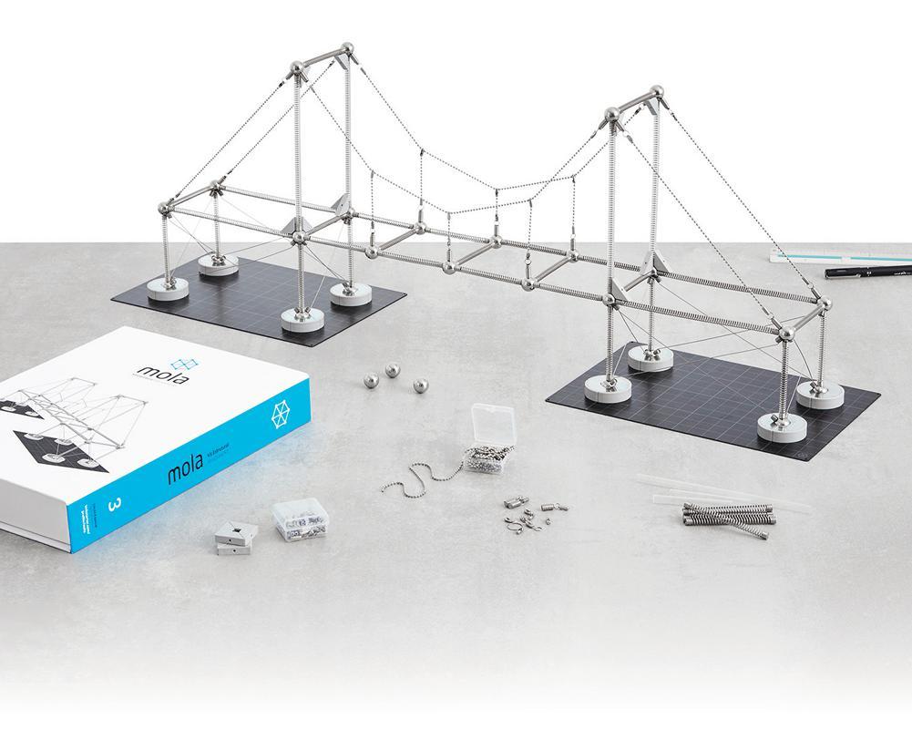
By Hannah Garfield, PE, and May Thu Nwe Nwe, Ph.D.When it comes to teaching teens about science, technology, engineering, and mathematics (STEM), hands-on experience is best. Even years later, students can still recall when they created a combustion reaction in high school chemistry class or were spun in a desk chair while holding textbooks in their outstretched arms to illustrate centripetal force in physics class. MOLA kits can serve as another memorable hands-on experience. These kits provide an interactive way for students to experience structural engineering by creating customizable and surprisingly accurate models.
The idea of a MOLA (meaning “spring” in Portuguese) Structural Model was first developed by Márcio Sequeira during a post-graduate architectural program in Brazil in 2004. The first Structural Kit (See Figure 1) was launched after ten years of design development in 2014 using a crowdfunding campaign. The kits include spring bars, joints, plates, diagonals, and bases that can realistically simulate how structural components behave in real life. Their ability to closely imitate structural behaviors was studied and validated by a series of tests at UFOP – Federal University of Oura Preto, Brazil. A bilingual manual in English and Portuguese is also included in each kit that explains the functions of different parts and illustrates how a set of modular components can be combined in countless ways to construct different structural systems. The kits are invented as a fun and intuitive way to learn abstract architectural and engineering design principles for people of all ages, from young kids to adult professionals.
The ACE Mentor Program (ACE) has been an ideal environment to use the kits as a teaching tool. ACE is a free afterschool program that brings together high school students to learn about architecture, construction, and engineering directly from industry professionals. Gilsanz Murray Steficek (GMS) has participated in ACE since 2006, teaching high school students about structural engineering, and introduced the kits to our students after participating in the 2014 crowdfunding campaign. After a brief presentation on the basics of structural engineering and three types of lateral systems: moment frames, braced frames, and shear walls, we challenge our ACE students to use the kits to build the tallest tower they think can survive an “earthquake” while using at least two different lateral systems. The “earthquake” is simulated on a rudimentary shaker table constructed from a tray filled with pencils.
The students come up with a wide variety of tower designs and even perform their own tests during the construction process to see how their structure reacts to the lateral load of, say, a student poking it. The students physically experience the differences in stiffness between the three types of lateral systems created with the parts. Some students learn the consequences of having a soft story first-hand. At the end of the ACE session, students present their structure to the class and test their build on the shaker table. Through their experience with the kits, students can easily identify different lateral systems in their structure, explain which systems provide more rigidity and why, and infer which structures might perform best on the shaker table. And, perhaps most importantly, the students yell and laugh as they watch their towers ultimately collapse in the “earthquake,” undoubtedly creating a memory that would solidify their experience with structural engineering. The kits can also be useful for students at a higher level of education, such as undergraduate and graduate students. In undergraduate-level classes, students will start learning physics behind different types of structural elements such as trusses and frames, different types of connections such as hinged and rigid connections, different types of structural loads such as vertical (gravity) and horizontal (lateral) loads, different types of structural stresses such as axial, shear, and bending
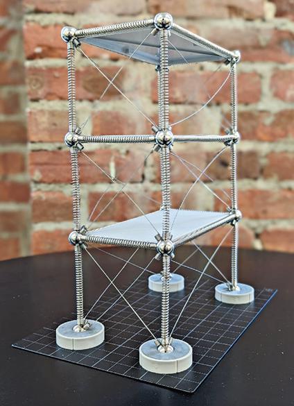
stresses, and different types of structural deformations such as translations and rotations. The kits can serve as a learning tool to demonstrate fundamental structural behaviors such as how a truss element and a frame element behave differently, how a hinged joint and a rigid joint create different deformations in the adjacent connecting pieces, and whether an element would take gravity and/ or lateral loads. For graduate students who learn advanced structural theories that are heavily based on abstract mathematics and physics, it can be challenging to develop an intuition for the behaviors of complex structural systems such as indeterminate (redundant) structures. Building a 3D prototype of the whole structure and visually assessing its gradual deformation provides a powerful learning advantage. Students can develop stronger intuition for how each structural piece would deform and how that would bring about the overall deformation of the entire structure. The kits can serve as a learning tool for connecting abstract concepts learned in classes to reality. For example, in the graduate-level Structural Stability class at Johns Hopkins University, graduate students use visual aids such as the kits to understand the differences among various buckling failure shapes that are hard to demonstrate on a 2D piece of paper or a whiteboard. Moreover, creating countless combinations using a set of modular pieces can improve their structural intuition and creativity as future practicing professionals. Physically building something and experimenting with different geometric shapes can help understand why certain structures are better than others.
The kits are a valuable teaching tool, whether the students are teens who are entirely new to engineering or structural engineering graduate students. The kits provide flexibility to allow the user to experiment and create various structures while maintaining structural accuracy. This hands-on approach is more accessible than computer modeling. It allows the student to experience the consequences of loads on their structure directly. Though, the kits are not for everyone. The small parts in a kit do not make it suitable for younger children, and the cost of a kit can be prohibitively expensive for some. However, overall, the kits are a helpful aid in training the next generation of structural engineers and in piquing students’ curiosity about structures and stability.■
Cast Connex
Phone: 888-681-8786
Email: info@castconnex.com
Web: http://www.castconnex.com/
Product: Timber End Connectors
Description: Clevis-type fittings designed to connect to the ends of heavy timber or glue-laminated structural elements loaded in predominately tension or compression for use in architecturally exposed applications. Visit our website to view the TEC and our custom cast steel connectors for timber projects.
ENERCALC, LLC
Phone: 800-424-2252
Email: info@enercalc.com
Web: https://enercalc.com
Product: ENERCALC SEL / ENERCALC 3D
Description: Deadlines getting to you? Whether working with wood beams, trusses, columns, ledgers or shear walls, ENERCALC SEL saves hours of design time weekly. Built-in databases for sawn lumber and engineered wood products (VersaLam, Glu-Lam etc) put section properties and allowable stresses at your fingertips. Budgetfriendly all-inclusive subscriptions make it easy.
WOODPRODUCTSguide
RISA Technologies
Phone: 949-951-5815
Email: benf@risa.com
Web: risa.com
Product: RISA-3D & RISAFloor
Description: RISAFloor and RISA-3D form the premiere software package for wood design. Create 3D models of your entire structure and get complete design of wood walls, flexible diaphragms, dimensional lumber, glulams, parallams, LVL’s and joists. Custom databases for species, design of strap and hold-downs as well as panel nailing offer flexibility.
Trimble
Phone: 678-737-7379
Email: jodi.hendrixson@trimble.com
Web: http://www.tekla.com/us
Product: Tekla Structures
Description: Can be used for wood framing: True BIM model of wood framing, parametric components allow for easy creation and design change, easily add or move doors and windows, clash checking functionality to eliminate change orders, easily customizable to suit any job requirements.
Product: Tekla Tedds

Description: Using Tekla Tedds you can design a range of wood elements, and produce detailed and transparent documentation for beams (single span, multi-span and cantilever), wood columns, sawn lumber, engineered wood, glulam and flitch options, shear walls (multiple openings: segmented or perforated) and connections (bolted, screwed, nailed, wood/wood and wood/steel).
ADVERTISEMENT–For Advertiser Information, visit STRUCTUREmag.org
YEARS OF REBAR TYING TOOLS
Listings are provided as a courtesy, STRUCTURE is not responsible for errors.
structural QUALITY
Bridge Construction Quality Control through Inspection
By Mr. Chidiac, P.E.Bridge construction differs greatly from other horizontal and vertical construction and thus involves targeted design and construction methodologies specific to the bridge type, size, and location. Transportation industries and other roadway users could suffer great economic losses when bridges at all levels of service are not well designed, constructed, and maintained. This article discusses bridge quality control through inspection.
Quality construction is achieved through the culmination of well-integrated design, construction, and inspection elements. Those elements include, at a minimum:
• Thorough investigation of the Construction Site to include sufficient geotechnical data required for the type of structure
• Clear and well-detailed construction plans, Owner’s Standards, and Construction Specifications, including Special Provisions for Special Situations, as well as:
ˏ Construction Quality Inspection Processes for offsite production of construction materials and on-site labor conformance with the construction documents
ˏ On-site sampling and testing of construction materials during placement, material curing, and timely loading of bridge elements are all integral to a successful project.
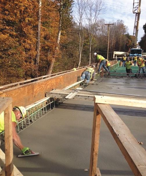
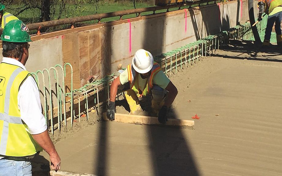
Workmanship and care during the performance of construction activities are decisive factors in the longevity or the premature failure of the project features (structural and non-structural). Rework or premature failure of material caused by incorporating material that does not meet the owner’s specification, costs, time, and money (typically absorbed by the contractor), delays and produces elements that are compromised to a certain extent.
Reference to the owner’s bridge construction standards must also be clear and include the proper version of the standards incorporated during the design. Large projects take longer to
design while the owner continues to refine and update construction standards. Therefore, the contractor and inspection staff must ensure that the proper standards are used for the corresponding structural elements. Such standards provide for minimum and maximum dimensions, rebar clearances, bending, splicing, welding, material designation, and similar details.
Construction specifications and owner publications include:
•Construction methods
•Call out allowed materials, approved suppliers, various material specifications, the applicable testing methods, and acceptable result ranges,
•Sampling testing frequency of construction materials,
• Placement of certain equipment (such as concrete pumps and other delivery and finishing equipment),
•Material curing and loading strength of structural elements. Such specifications must be followed and can only be substituted with the owner’s approval through proper and timely submittal of Requests For Information (RFIs). To ensure that contract documents are followed, the owner typically allows the Inspector in Charge (IIC) to accept minor deviations or material substitution based on their experience as the owner’s representative and years of experience in similar construction. Still, in most situations, changes/substitutions must be submitted to the owner’s engineer for concurrence BEFORE incorporation in the final product.
Examples of improper construction that can cause low quality: driven bearing piles in place of pre-drilled pile holes due to obstructions resulting in shallow and capacity-deficient pile foundation; driving foundation piles with the improper hammer size, min and max strokes, or an improperly operating hammer yield lower pile capacity
than that called for in the construction plans; larger capacity hammers that may cause broken welds at pile splice locations; stopping a friction pile at a certain planned pile tip elevation without the proper dynamic and/or static load testing; not following the proper heat, number of passes, weld sizes, types, and the proper welding process in the case of field welding of structural components, driven piles, etc.
Properly documenting actual conditions validates adequacy in case of premature failure, etc. Examples of critical information include details of sampling, testing, placements of various elements, weather and site conditions during each activity, the various dimensions, sizes, clearances, and product names of materials used, the manufacturer’s name, type, size, and capacity of equipment used in specific activities.
Bridge foundations must meet or exceed the specified design capacity and be approved by the owner’s engineer; any suspect material (soil or rock) must be removed and replaced as approved by a geotechnical engineer. Allowing unprotected original foundation soils or highly decomposed/ weathered rock (such as mica schist) subject to weather deterioration to remain without removal and replacement with suitable material of equivalent or higher capacity results in reduced foundation capacity.
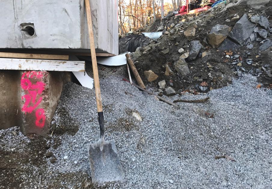
The placement of precast elements and removal of support after posttensioning are also critical elements for the inspection. Box culvert segments cannot be undermined once the foundation is placed, compacted, and the box segments are installed and post tensioned. Some plans call for the wing footer to be a few feet below the bottom slab; the overexcavation required to install the footer loosens and destabilizes the foundation materials causing the forces in the post-tensioning cables (designed to pull the box culverts tightly) to exceed the design forces. The resulting voids under the bottom slab can never be replaced and
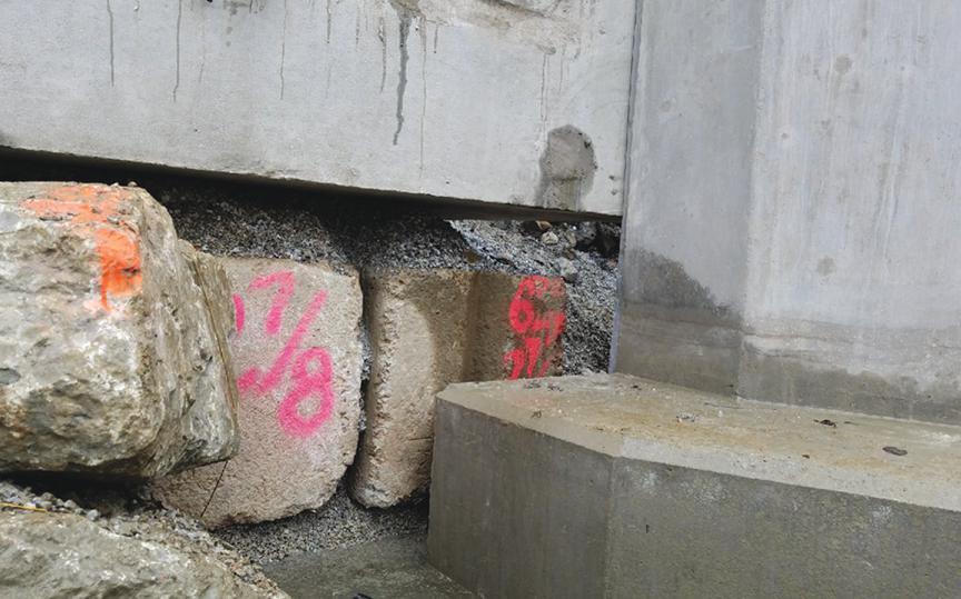
compacted to the required design foundation capacity.
Using epoxy rebar where the epoxy coating is damaged during handling or rework (removing and replacing concrete), especially in areas where moisture continuously exists or the concrete surface is subject to de-icing chemicals and other corrosive environments, will decrease the longevity of the epoxy coating and will allow rust to propagate throughout the reinforcement bars.
Other undesirable conditions include:
•Cold joints that are not per construction plans, especially in bridge decks and multiple-span continuous construction, must be avoided or re-evaluated by the design engineer. Keyed construction joints are very useful in areas where cold joints were not planned and cannot be avoided due to special circumstances.
•Multiple small pours vertically or horizontally in structural elements
• Incompatible paint layers in field painting of steel structures or not following required cure times to recoat cause premature failure of the paint system.
• Ignoring minimum and maximum air content, especially in colder regions, decreases the life span of concrete.
• Ignoring maximum water content and minimum/maximum slump limits leads to strength deficiencies and workability issues. Early static loadings of bridge elements must not exceed specificationallowed loads, whether structural or not. Most bridge owners have minimum loading strengths for the various bridge components which must be followed unless waived by the owner. No existing or new bridge can be used to store materials or equipment unless approved by the owner after thorough analysis and approval of the loading plan by the owner’s engineers. If such plans were approved, the contractor must strictly adhere to the designated areas and stated loads with no deviations. Live loads must not occupy or traverse a new bridge deck until the deck has met the curing duration and the minimum required strengths specified by the owner.
All stakeholders must be committed to providing quality construction and working together to resolve issues efficiently without sacrificing quality for personal gains.■
Mr. Chidiac, P.E. is a Construction Engineer with TRC in Pennsylvania. He is a registered Professional Engineer in 12 states with 35 years of experience; 21 years of his experience was spent as an employee of the PA Department of Transportation. Since joining TRC over ten years ago, Mr. Chidiac has served in a variety of QA roles including Construction Quality Acceptance Manager, Structure Control Engineer, Construction Engineer, Constructability Reviewer, and CPM Schedule Reviewer. He also conducts periodic training sessions for TRC staff in the performance of QA inspections specific to structures-related work.
New Code Provisions for GFRPReinforced Concrete and Structural Concrete Repair
By Stephen S. Szoke, P.E., F.ACI, F.ASCE, F.SEI, David G. Tepke, P.E. F.ACI, M.ASCE and William Gold, P.E. F.ACIThe 2024 International Code Council model building codes will reference two additional American Concrete Institute (ACI) concrete design and construction standards. ACI CODE 440.11-22 Building Code Requirements for Structural Concrete Reinforced with Glass Fiber-Reinforced Polymer (GFRP) Bars (440.11) will be referenced by the International Building Code (IBC) and ACI CODE 562-21 Assessment, Repair, and Rehabilitation of Existing Concrete Structures (562) will be referenced by the International Existing Building Code (IEBC). Although adoption by authorities having jurisdiction (AHJ) will dictate when provisions become explicitly adopted in a particular area, these standards represent current state of the practice and can be used in the interim through an appropriate alternative means and methods process.
GFRP Reinforced Concrete
ACI Committee 440 developed CODE 440.11 to establish minimum requirements for the strength, stability, serviceability, durability, and integrity of GFRP-reinforced concrete structures. The standard is modelled after ACI CODE 318 Building Code Requirements for Structural Concrete and currently limited to the design and construction of cast-in-place reinforced concretes with GFRP reinforcing bars meeting ASTM D7957 Standard Specification for Solid Round Glass Fiber Reinforced Polymer Bars for Concrete Reinforcement shown in Figure 1.
Benefits and Uses of GFRP
Compared to steel reinforcing bars, the lighter weight of GRFP reinforcing bars are easier to install and may reduce the overall structure’s weight. The bars are non-metallic, so they are not susceptible to electrochemical corrosion that may result from chloride exposure in coastal areas or where chloride deicing salts are used. Thus, properly designed structural concrete with GFRP reinforcement may have improved performance in corrosive environments, such as coastal, marine, and parking garage structures. The non-magnetic nature of GFRP bars is beneficial in facilities housing electromagnetic-sensitive equipment, such as Magnetic Resonance Imaging (MRI) machines.
Limitations
ACI CODE 440.11 permits the use of structural concrete reinforced with GFRP reinforcement for all structural elements in Seismic Design Category (SDC) A and elements not part of the seismic lateral force-resisting system in structures assigned to SDC B and C. However, the proposed language in the 2024 edition of the IBC
limits applications to structures assigned to SDC A. GFRP bars are not permitted to be used in any structural member in a structure assigned to SDC D, E, or F. These restrictions are applied to the use of GRFP bars because they are not ductile. Although GRFP is linearly elastic to failure, beyond the failure point there is no ductility and moment redistribution is limited. Inelastic analysis is not permitted in design of GRFP structures.
Due to the lower resistance to elevated temperatures in comparison to conventional steel reinforcing, ACI CODE 440.11 does not permit the use of structural concrete reinforced with GFRP bars in fire-rated construction, except where structural fire resistance has been shown by calculations or tests and approved by the building official. ACI CODE 440.11 additionally requires that bars not be used in environments with a service temperature higher than 27oF below the glass transition temperature of the bar. ASTM D7957 requires bars to have a minimum mean glass transition temperature of 212oF. GFRP bars with glass transition temperatures over 250oF are commercially available.
The Commentary in CODE 440.11 and information in ACI PRC 440.1R-15 provide additional context on elevated temperature performance, implications, and recent research. In Type IIIB construction and except for exterior walls in Types IIB and VB construction structural elements are not required to have fire resistance ratings. Thus according to types of construction and occupancy and use in Chapters 5 and 6 of the International Building Code there are many acceptable applications of GFRP bars. For instance, schools, four stories or less; businesses four stories or less; and hotels, motels, apartment buildings, and condominium buildings five stories or less are permitted as Type IIB construction for fully sprinklered buildings. Refer to the specific requirements of the IBC for an individual project.
Differences in Detailing and Design
Concrete reinforced with GFRP reinforcement behaves differently than concrete reinforced with steel reinforcement, resulting in different detailing requirements, serviceability considerations, and strength calculations. When compared to steel bars, GRFP bars have a higher transverse coefficient of thermal expansion, larger strains at service loads, and exhibit different mechanical and bond behavior resulting in the following differences in detailing requirements:
•Different skin, secondary side face, reinforcement spacing,
•Closer tie spacing for compression members,
• Greater cover for large bar diameters in structures that experience considerable thermal cycling,
•Different stirrup anchorage requirements, and
•Different development lengths.
Serviceability
GFRP bars have a higher tensile strength, but a lower modulus of elasticity than steel bars. Thus, GFRP flexural members are typically governed by serviceability, rather than by ultimate strength. Deflections must always be calculated and checked against limits for flexural members. At code-prescribed reinforcing levels, crack widths at tension faces may be greater in GRFP-reinforced members than in steel-reinforced members. Thus, additional reinforcing may be required or desired to reduce crack widths. Crack control may not be as critical where GFRP is used because of its corrosion resistance. Concrete reinforced with GFRP may have different time-dependent deformation characteristics than conventional reinforced concrete. Per the Commentary, GFRP in the compression zone can not be considered in ACI CODE 440.11 equations for reducing creep due to the limited effect. Time-dependent deflection, when considered as a multiple of the instantaneous deflection, is lower; and the creep multiplier is calculated differently.
Strength
Because GFRP-reinforced concrete sections do not exhibit ductile behavior, there are lower resistance factors are used to calculate moment, axial, and combined moment/axial behavior (0.55 for tension-controlled transitioning to 0.65 for compression-controlled). Since GFRP has a lower transverse strength and modulus than reinforcing steel, dowel action (the shear strength of cracked reinforced concrete) is assumed to be lower for sections containing the same area of reinforcing steel making shear capacity less on that basis.
Slenderness limits for compression members are reduced, and the effective stiffness of members is generally lower. Compared to concrete reinforced with steel bars, the required amount of GFRP for equivalent force capacity for temperature and shrinkage reinforcement is generally larger; the axial stiffness of GFRP reinforcement significantly impacts punching shear response; axial capacity of walls is reduced; and longitudinal torsional reinforcement diameter in comparison to
transverse reinforcement spacing must be greater.
Research is still limited in some areas; there are currently no provisions in ACI CODE 440.11 for:
•Earthquake-resistant structures
•Deep beams
•Two-way joist systems
•Connection of precast members
•Use of strut-and-tie models
•Use of GFRP reinforcement with lightweight concrete

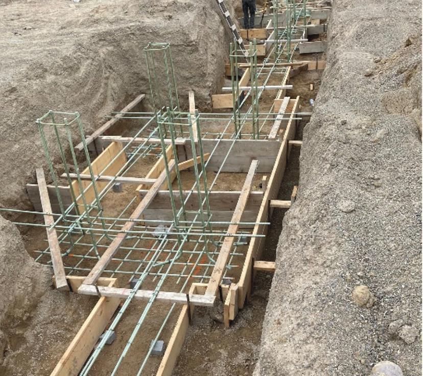
•Prestressing or post-tensioning using GFRP.
•GFRP-reinforced diaphragms
•Use of GFRP for shear-friction
Assessment, Repair, and Rehabilitation of Existing Concrete Structures - Uses and Limitations of ACI CODE 562
ACI CODE 562 was originally published in 2013, and most recently updated in 2021. It was developed to provide provisions for structural concrete repair, such as that represented in Figure 2.
The Code provides minimum requirements for assessing, repairing, and restoring structural concrete elements in existing structures. It is also intended for use for non-structural or aesthetic improvements if failure of such repairs would result in a dangerous condition. In all cases, repairs and restoration in accordance with the current building code adopted by the AHJ are permitted. ACI CODE 562 is intended as a compliance alternative to the existing building code. ACI CODE 562 is structured for use either as a stand-alone code or for use as a supplement to an existing building code. As with all reference standards, where there are conflicts, the jurisdictional code prevails. Where used with an existing building code, ACI 562 provides the methods to determine loads, evaluate/assess the structure with reduction factors, and addresses design, durability, construction, and quality assurance. Where used as a stand-alone code, ACI 562 also addresses preliminary assessment, general provisions, and load factors.
Seismic Force-Resisting Systems
ACI CODE 562 is applicable for repairs that do not change the strength, stiffness, or ductility of the seismic-force-resisting system. It is not applicable for strengthening those elements. Where such conditions exist, assessment, repair, or restoration should be in accordance with the provisions of the building code adopted by the AHJ (based on the International Existing Building Code or Chapter 34 of the IBC) and the American Society of Civil Engineers/Structural Engineering Institute 41 (ASCE/SEI 41) Seismic Evaluation and Retrofit of Existing Buildings.
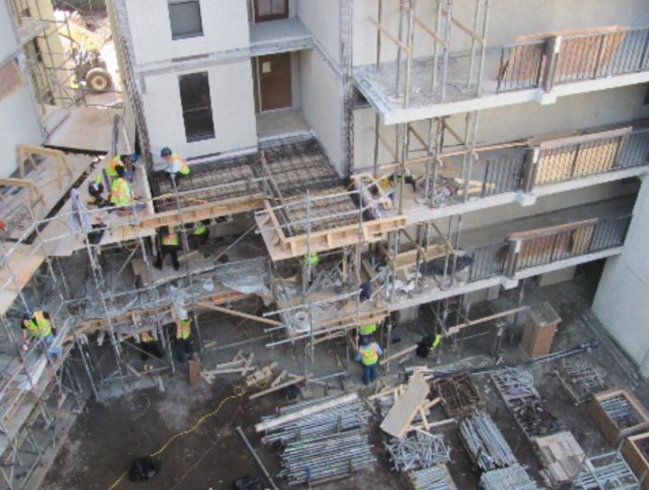
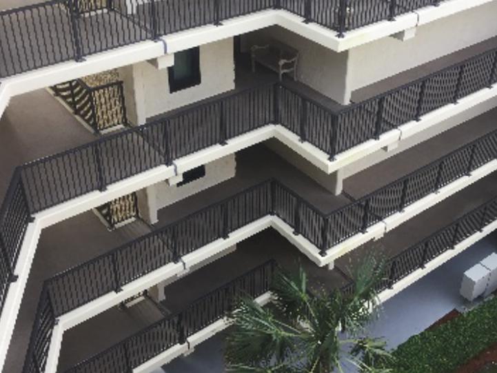
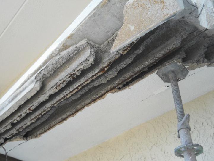
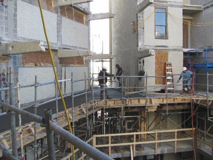
ACI CODE 562 provides maximum strength reduction factors for restoration design and assessment. Load combinations are included for external strengthening subject to damage, vandalism, and fire. Any loads and deformations associated with damage, deterioration, load removal, construction sequencing and temporary actions such as jacking in post-tensioned anchorage zones require consideration. Assessment, evaluation, and analysis are to be conducted to establish conditions, define causes of distress, and develop appropriate rehabilitation strategies. Investigation and evaluation are required where insufficient information is available or there is reason by the design professional to question capacity compared to design demands. Where required, the analysis is to consider in-place structural dimensions, structural alterations, loads or occupancy, and in-place material
properties. Concrete compressive strength and steel yield strength may be determined from the original construction documents, historical properties indicated in ACI CODE 562, or physical testing. If material properties are determined through sampling and testing, increased resistance factors are permitted. Equivalent concrete compressive strength and reinforcing steel strength can be based on simplified equations for statistical evaluation or nondestructive testing where valid correlations with destructive testing are developed.
The structural analysis must consider the maximum effects due to gravity and lateral loads and consider conditions such as material properties, geometry, deformations, lateral drift, load duration, timedependent deformations, interactions with foundations, material deterioration, bond loss, redistribution of forces (in members and the structural system), load paths, previous repairs, and previous structural modifications. Serviceability issues, if identified, are to be evaluated. The structural analysis must also consider the repair process, including sequencing and material removal, and load testing permitted as part of the evaluation.
Design must meet the strength requirements of the design-basis code and consider loading, internal forces, and deformations to the existing and repaired structure during the repair process. Repairs must be integrated with the existing structure, including necessary load transfer and load sharing. Design must consider stresses at the bond line between the repair material and the existing concrete.
Bond integrity testing is required where the interface shear stress is less than or equal to 30 psi; qualitative bond testing is necessary if greater than 30 psi unless interface reinforcement is designed per ACI CODE 318. Interface reinforcement is required if shear stresses are greater than 60 psi.
Existing materials may remain if performing satisfactorily; however, stresses are not to exceed those in the original basis of design. Stress concentrations and cracking must be considered with respect to repair geometry and configuration. The design of external fiber reinforced polymer wraps (FRP) for strengthening must have adequate unrepaired strength and FRP materials should comply with ACI SPEC 440.6 and ACI SPEC 440.8. Where determined by required consideration of elevated temperatures, supplemental protection is permitted.
ACI CODE 562 considers the properties and installation of repair systems. Damaged or corroded reinforcement is permitted to remain if the effective remaining cross-sectional area is used in the design and the impact on development and damage to deformations is considered. Any post-installed anchors shall comply with ACI CODE 318. Both new and existing reinforcement must be adequately developed. The effects of prestressing on the structure, if applicable, must be considered, including damage, geometry, losses, and repair sequence. Design with supplemental post-tensioning is required to consider stresses, limitations of the original design basis, load transfer, impact on adjoining construction, losses, deflections, adequate unrepaired strength for externally post-tensioned repairs, and other conditions.
Durability
Design must consider the causes of current conditions, defects, and potential deterioration of repairs, as well as serviceability. The impact of cracks on the durability of the repair and structure must be considered in the design. Causes of cracking, movement, size, orientation, width, pattern; substrate, location and water penetration must be assessed.
Corrosives and the presence of corrosion products, if not removed from reinforcement during repair, must be considered with respect to impact on the structure design life. The quality of the existing concrete and its capability to protect the reinforcement from corrosion, fire, and other damage must be evaluated. The cover must be sufficient to provide adequate fire protection, corrosion protection and reinforcement anchorage/development. The code has provisions for consideration of galvanic corrosion; however, protection with electrochemical methods must consider interaction with repaired elements, the structure, and the environment. Materials and reinforcement used in the design must be compatible with the structure and environment and may not adversely affect the durability of other materials.
Construction Documents
Additional items identified in ACI CODE 562 that are to be including in construction documents are:
•Contractor quality control requirements.
• Stability and temporary shoring design and requirements, including:
ˏportions requiring shoring,
ˏdesign loads and spacing requirements, and
ˏ contractor responsibilities for providing and maintaining shoring.
• Considerations for shoring, including provisions for shoring being designed by a licensed design professional, and global stability.
•Temporary conditions and environmental issues, including hazardous materials.
•Post-tensioning repair sequence, if applicable.
•Inspection, testing, and construction requirements including:
ˏRequirements for inspection of existing reinforcement,
ˏRequirements for inspection of existing conditions prior to concealment from repair,
ˏFrequency of tests and reporting requirements, and
ˏRequirements for record retention.
Closing
ACI committees have developed both standards following strict American National Standards Institute (ANSI) accredited procedures. While both standards represent the current state of practice in the industry for minimum requirements for safe design and are maintained by industry experts. They provide flexibility for implementation by design professionals and introduce additional options and concepts.
Additional Resources
Additional ACI codes, specifications, and guides relevant to the design and construction of structural concrete reinforced with GFRP rebar and for the repair of existing structural concrete elements include: ASCE/SEI 41 references:
ACI 214.4R, Guide for Obtaining Cores and Interpreting Compressive Strength Results
ACI 228.2 Report on Nondestructive Test Methods for Evaluation of Concrete in Structures
ACI CODE 562 references:
ACI CODE 369.1 Standard Requirements for Seismic Evaluation and Retrofit of Existing Concrete Buildings
ACI CODE 437.2 Code Requirements for Load Testing of Existing Concrete Structures
ACI SPEC 440.6 Specification for Carbon Fiber-Reinforced Polymer Bar Material for Concrete Reinforcement
ACI SPEC 440.8 Specification for Carbon and Glass FiberReinforced Polymer Materials Made by Wet Layup for External Strengthen
ACI CODE 440.11 references:
ACI SPEC 440.5 Construction with Glass Fiber-Reinforced Polymer Reinforcing Bars – Specification
ACI 440.1 Guide for the Design and Construction of Structural Concrete Reinforced with Fiber-Reinforced Polymer Bars■
Stephen S. Szoke, P.E., F.ACI, F.ASCE, F.SEI is a Code Advocacy Engineer with the American Concrete Institute. He has over 45 years of experience representing concrete and masonry interests related to the development and maintenance of codes, standards, and regulations.
David G. Tepke, P.E. F.ACI, M.ASCE, is a Principal Engineer at SKA Consulting Engineers, Inc. He is experienced in structural and materials investigations, durability design, and structural rehabilitation; and serves on ACI, ICRI, AMPP, and AWS committees on corrosion, service-life, durability, codes and specifications related to reinforced concrete. He is a NACE/ AMPP Certified Corrosion Specialist.
William Gold, P.E. F.ACI is an Engineer with the American Concrete Institute. He has over 25 years of practical experience using FRP material systems. He uses that experience to disseminate knowledge on these systems and other technologies.
Structural Lightweight Concrete Contributes to Seismic Resistance
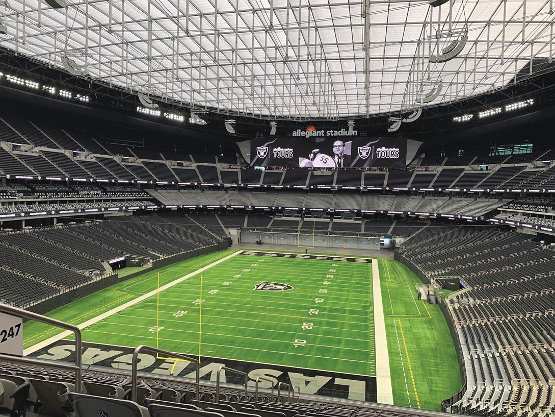
The key is not too much of a good thing.
By Michael RobinsonDesigning structures that resist failure due to seismic activity safeguards occupants from injury and reduces the need to rebuild after an earthquake, which can decrease the total embodied carbon a site represents. As such, seismically resilient structures contribute to sustainable construction practices by reducing the environmental strain caused by material production, transportation, and construction.
Concrete can provide considerable strength to structures and, if reinforced properly, can withstand seismic activity to some degree. But, in seismic design, too much of a good thing can be detrimental. For concrete, its strength can contribute to its brittleness. Brittle structures often perform more poorly during seismic activity when compared to more ductile ones.
There are many ways to offset concrete’s tendency toward brittleness—from steel reinforcement to adding fibers to the concrete mix. However, these options only address one aspect of seismic design. Despite tending to be more brittle than normal weight concrete (NWC), structural lightweight concrete (SLC) can contribute more seismic resilience to structures because it has a lower density, which reduces dead loads. Further, SLC can lower the material requirements of foundation and support systems without compromising strength. And while SLC made with expanded shale, clay, or slate (ESCS) initially costs more than NWC (with exact cost differences depending on a site’s distance from a ESCS production plant), it can reduce costs across the entire structure for significant net savings. This is true even if the material needs to be shipped from distant production sites.
As such, SLC contributes to a structure’s seismic resilience and sustainability. With this in mind, engineers specifying SLC made with ESCS can mitigate concerns about brittleness while supporting other forms of seismic resilience—including lower densities. It is important to note that SLC mixes can be adjusted within limits to achieve a desired ratio of strength to total weight for a structure.
Lower Density with Comparable Strength
Perhaps the primary reason for using SLC in seismically conscious design is to reduce the dead load, which allows for smaller beams, columns, and footings. These reductions weaken earthquake forces acting on a structure resulting in improved seismic resistance.
For example, the Benicia-Martinez Bridge, a lifeline roadway in the San Francisco Bay Area, is located three miles west of the Green Valley Fault. Therefore, it needed to be engineered to resist failure due to earthquakes. The U.S. Coast Guard required increasing the original span lengths across the navigational channel from 525 feet to approximately 660 feet. This change, combined with the seismic challenges, pushed the limits for cast-in-place balanced cantilever construction in a high seismic risk zone. After testing more than 30 lightweight concrete mixtures, the engineers specified an SLC with a density range of 120 – 125 pounds per cubic foot (pcf)—15 percent less than NWC. It also has a minimum modulus of elasticity of 3.4 x10⁶ psi at 28 days. The choice of lightweight, high-performance concrete was the key to achieving these span lengths. Reduced superstructure
dead loads mitigated the force the structure would exert on piles, footings, and piers in a seismic event.
The benefits of reduced density extend beyond bridge construction. As evidenced in a recent Salt Lake City Airport expansion, SLC at 110 pcf reduced dead loads to account for poor soil conditions and as a precaution for seismic activity. Likewise, Allegiant Stadium in Las Vegas, Nev., utilized concrete 25 – 35 percent lighter than NWC to improve seismic resilience. The reduced mass of both projects abates the movement the structures experience during an earthquake.
Resilience and Sustainability
Regardless of seismic design requirements, SLC reduces foundation and dead loads, which results in fewer piles, smaller footings, less reinforcing, and smaller supporting members. When considering a structure as a whole, using SLC promotes structurally sound projects requiring less building material quantities. Further, due to SLC’s improved insulative qualities, floor slabs can be made thinner while still meeting fire code requirements and offering comparable
or improved thermal conductivity for energy-efficient structures. In addition, the reduced modulus of elasticity and reduced coefficient of thermal expansion of SLC, and the internal curing water provided by ESCS aggregate in SLC, all contribute to reduced concrete cracking, which is important for concrete durability and especially important for durable bridge decks.

These qualities can both offset the initially high environmental impact of producing SLC from ESCS and even reduce the overall carbon footprint of an entire building. In addition, the material’s sustainability benefits are increased when earthquake reconstruction costs are considered.
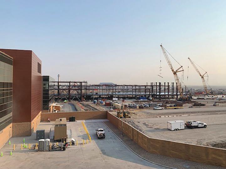
Rather than rebuilding a complete structure or executing considerable repairs, professionals can reduce the material and energy that a site would otherwise need by engineering seismically resilient structures that resist failure. Likewise, reducing the risk of failure during seismic activity can mitigate the chances of environmentally hazardous materials being released into the atmosphere. Finally, seismically resilient buildings help cities avoid overburdening landfills with potentially harmful debris by sidelining the need to demolish and rebuild.
All of these benefits contribute to structures that enhance the return on investment economically (through their long-term durability) and improve the sustainability of a project (by decreasing total life-cycle energy and material requirements through resiliency). Therefore, specifying SLC made from ESCS lightweight aggregate, a readily available material, can help improve the seismic resilience of a structure and, by extension, reduce its impact on the environment.■
Full references are included in the online version of the article at STRUCTUREmag.org.
Flexural Design of Reinforced Concrete Beam Sections
This Part 1 of the article focuses on the flexural strength calculation of any given beam section.
By Qian Wang, Ph.D., P.E., LEED AP, and Shahriar Quayyum, Ph.D., P.E.Flexural analysis and design of beam sections are fundamental topics in reinforced concrete structures. However, many engineers and students have difficulty generalizing the basic analysis and design principles into more general and complex cross-sectional shapes other than simple rectangular cross-sections. This article presents the flexural analysis and design of general beam sections in a rigorously derived framework and builds a foundation for their design. Part 1: Section Analysis focuses on the flexural strength calculation (analysis) of any given beam section. Part 2: Section Design focusing on the flexural design aspects of beam sections will run in a future article.
For symbols not defined in this article, please refer to the American Concrete Institute’s ACI 318-19, Building Code Requirements for Structural Concrete
Section Analysis Basics
nominal flexural strength of the section. The plane sections normal to the beam axis remain plane so that the strain diagram is linear. According to ACI 318-19: 22.2.2.1, the maximum strain at the extreme concrete compression fiber is assumed to be ��cu=0.003.
The concrete stress of 0.85f' c (f' c is the specified compressive strength of concrete) is assumed uniformly distributed over an equivalent compression zone, Ac (ACI 318-19: 22.2.2.4.1); this is referred to as the Whitney stress block.
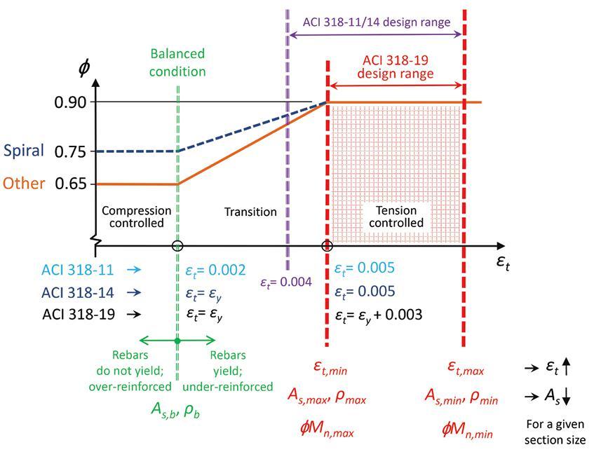
Assumptions
Figure 1 shows a reinforced concrete beam section’s strain, stress, and internal force diagrams. Several assumptions are made to compute the
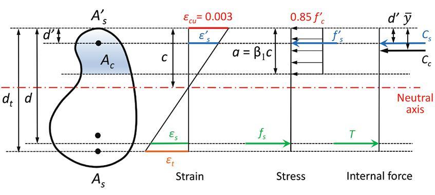
To compute the nominal flexural strength of a beam section, equilibrium of tension and compression is maintained, i.e.,
T=Cc+Cs (Eqn.1)
The resultant tension and compression forces are
T=As fs (Eqn. 2)
Cc=0.85f' c (Ac –A' s ) (Eqn. 3)
Cs=A' s f' s (Eqn. 4) where As and A' s are the tension and compression steel areas, and their respective stresses are fs and f' s . The strains in the tension and compression steel are ��s and �� ' s respectively. For singly reinforced sections, A' s =0 and Cs=0. For doubly reinforced sections, it is common to use an approximate equation of Cc, as
Cc=0.85f' c Ac (Eqn. 5) The equilibrium equation is written as
As fs=0.85f' c Ac +A' s f' s (Eqn. 6)
The design moment strength of a singly reinforced beam section is
��Mn =��[As fs (d–y)] (Eqn. 7) and the design moment strength of a doubly reinforced beam section is
��Mn =��[0.85f' c Ac (d–y)+A' s f' s (d-d' )] (Eqn. 8) where y is the distance from the center of gravity or centroid of Ac to the extreme concrete compression fiber. This represents the location of the resultant concrete compression, Cc. In Equations 7 and 8, d and d' are the distances
from the centroids of the tension and compression steel groups to the extreme concrete compression fiber, respectively.
ACI
318-19
To determine the strength reduction factor, ��, ACI 318-19 Table 21.2.2 defines the following three types of beam sections, depending on the ductility of the sections:
��=0.65; ��t≤��y; compression-controlled
��=0.65+0.25 ; ��y<��t<��y+0.003; transition (Eqn. 9)
��=0.9; ��t≥��y+0.003; tension-controlled
where ��t is the strain in the extreme (bottom) layer of tension steel and is calculated based on dt, which is the distance from the centroid of the extreme layer of tension steel to the extreme concrete compression fiber. The yield strain of steel is
ACI 318-19 defines ��t =��y+0.003 as the start of tension-controlled sections instead of ��t =0.005, which was used in previous ACI 318 editions. For Grade 60 steel, ACI 318-19 is consistent with the two previous editions. The difference between ACI 318-11, ACI 318-14, and ACI 318-19 is shown in Figure 2. Before ACI 318-19, a transition section with 0.005>��t ≥0.004 is allowed for beam design; however, in ACI 318-19, only tension-controlled sections (��=0.9) are permitted, i.e., ��t ≥ ��y+0.003.
Rectangular Sections
For rectangular beam sections, the relationship between the reinforcement ratio, ��=As /bd and strain, ��t , is as follows:
(Eqn. 10)
The design moment strength of a rectangular section is
��Mn =��[Rn(bd 2)]
(Eqn. 11) where Rn is the flexural-resistance factor and is a quadratic function of ��. Depending on the given information, the rectangular section analysis and design may involve two types of calculations, i.e., Rn⟶ �� or ��⟶Rn , as

(Eqn. 12)
(Eqn. 13)
Section Analysis Procedure
For singly or doubly reinforced concrete beam sections, the analysis procedure includes 8 or 12 steps:
1.Assume all rebars yield. Based on the equilibrium condition, for a singly reinforced section
(Eqn. 14)
For a doubly reinforced section
(Eqn. 15)
2.(Shape) Calculate the depth of the Whitney stress block, α=α(Ac), and α is a function of Ac which depends on the shape of the cross-section.
3.Calculate the neutral axis depth, c= α/��1.


4.Verify the assumption that all rebars yield. For a singly reinforced section, calculate the strain in the rebars
(Eqn. 16) and checking whether this is greater than or equal to the yield strain of steel, ��y If the rebars yield, i.e., ��s ≥ ��y⟶ fs =fy , continue to steps 5a-8a; otherwise, go to steps 5b-12b.
For a doubly reinforced section, calculate the strains in both tension and compression rebars (Eqn. 17) and checking whether ��s and �� ' s are greater than or equal to the yield strain of steel, ��y
If both tension and compression rebars yield, i.e., ��s ≥��y ⟶ fs =fy , and �� ' s ≥��y ⟶f' s = fy , continue to steps 5a-8a; otherwise (if only tension rebars yield, or if only compression rebars yield, or if neither rebars yield), go to steps 5b-12b.
5a.(Shape) Calculate the center of gravity or centroid of Ac, which depends on the shape of the cross-section.
(Eqn. 18)
5b.Derive and solve an equation of c using the equilibrium equation. For a singly reinforced section


As fs =0.85f' c Ac
where , and Ac is a function of c, depending on the shape. For a doubly reinforced section
As fs =0.85f' c Ac+A' s f' s where fs =Es ��s =Es ��cu or or fy ,
and Ac is a function of c, depending on the shape.
6a. Calculate the flexural strength Mn using Equation 7 or Equation 8
6b.Calculate α=��1/c.
7a. Calculate the strain in the extreme (bottom) layer of tension steel using
(Eqn. 19)
and determine the type of section (i.e., compression-controlled, transition, or tension-controlled section) and ��
7b.Calculate the strain and stress in the rebars. For a singly reinforced section ; fs =Es ��s < fy
For a doubly reinforced section
For a reinforced section
; fs =Es ��s (do not yield) or fy (yield)
; f' s =Es �� ' s (do not yield) or fy (yield)
8a. Compute ��Mn.
8b.(Shape) Calculate the area of the equivalent compression zone, Ac = Ac (α), and Ac is a function of α. This step depends on the shape of the cross-section.
9b.(Shape) Calculate centroid of Ac,
10b.Calculate the flexural strength Mn using Equation 7 or Equation 8.
11b.Calculate the strain in the extreme (bottom) layer of tension steel using , and determine the type of section and ��.
12b. Compute ��Mn
Forward and Backward Analysis
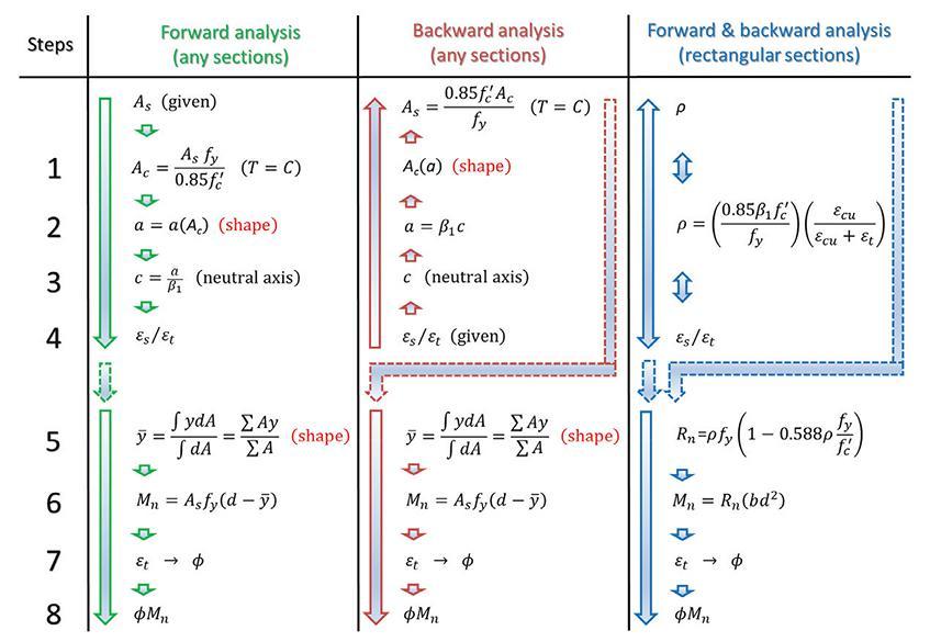
This section introduces the forward and backward analysis of singly reinforced beam sections, which are shown in Figure 3
The forward analysis starts with the given section and steel area, As , as
In the backward analysis, the strain value of the tension steel is given, and the steel area can be determined as ��t ⟶ c (neutral axis) ⟶
The nominal moment strength can be computed for both the forward and backward analysis, as shown in Figure 3. Since these are mainly used for design purposes, the tension steel is assumed to yield. The relationship between As , ��t , and �� is shown in Figure 4.
Lower and Upper Bounds
For any beam cross-section, the minimum and maximum areas of reinforcement allowed in a singly reinforced section can be calculated. For a given section size, the corresponding design moment strength values are the minimum and maximum values that can be determined, as shown in Figure 2. These lower and upper bounds define the permitted range of a beam section design based on ACI 318-19. The minimum steel area is determined according to ACI 318-19: 9.6.1.2. ACI 318-19: 9.3.3.1 indirectly specifies the maximum steel area requirement. A beam section has to be designed as tension controlled (��=0.9), and the strain ��t shall be greater than or equal to (��y+0.003), which is a lower bound strain value. A backward analysis is required to determine the maximum steel area permitted in a singly reinforced beam section. In many cases, the maximum steel area requirement controls the beam design to reduce
the beam size and weight that may be required for architectural considerations or other reasons.
For the analysis and design of rectangular sections, it is straightforward to check the lower and upper reinforcement ratio limits directly. The balanced reinforced ratio ��b and maximum reinforcement ratio ��max can be directly determined using Equation 10, and these values, as well as the minimum reinforcement ratio, ��min, are listed in the Table. The minimum and maximum design moment strength of a rectangular section can be computed using Equation 13, (��⟶Rn), and Equation 11.
Summary
1)Different analysis methods for reinforced concrete beam sections are available, such as the trial-and-error approach. This article presents a general analysis framework of singly reinforced and doubly reinforced general beam sections. This is a rigorously derived approach for any general section, which can be done by hand or implemented in a spreadsheet.
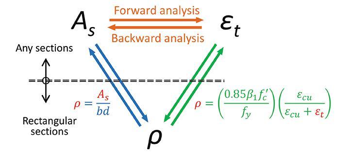
2)The latest ACI 318-19 code requirement for flexural strength is introduced, and the difference between this edition and previous editions of ACI 318 is briefly reviewed.
3)The steel area range and flexural strength range permitted by ACI 318-19 for singly reinforced beam sections are discussed and can be computed for any cross-sectional shape. This provides the lower and upper bounds for a new beam design.

4)This article serves as supplementary material to any reinforced concrete textbook for a better understanding of the topic.
5)Part 2 of this article, in a future issue, will discuss the flexural design of beam sections.■
References and a numerical example are included in the online version of the article at STRUCTUREmag.org.
Qian Wang is an Associate Professor in the Department of Civil and Environmental Engineering at Manhattan College, Riverdale, NY (qian.wang@manhattan.edu).
Shahriar Quayyum is a visiting Assistant Professor in the Department of Civil and Environmental Engineering at Manhattan College, Riverdale, NY.
Eliminate
Negative volume change
Control joints
Curling
Maximize extended joint spacing
Improve structural performance
Maintain dimensional stability
Lower permeability
Maximize long-term durability
Enhance strength and abrasion resistance
A Numerical Example – online only
Given a beam section, as shown in Figure 5, use f' c =3,000 pounds per square inch (psi) and Grade 60 rebars (fy =60 kips per square inch [ksi]). The beam section is analyzed using the forward and backward analysis methods outlined in this article. Consider the following cases:
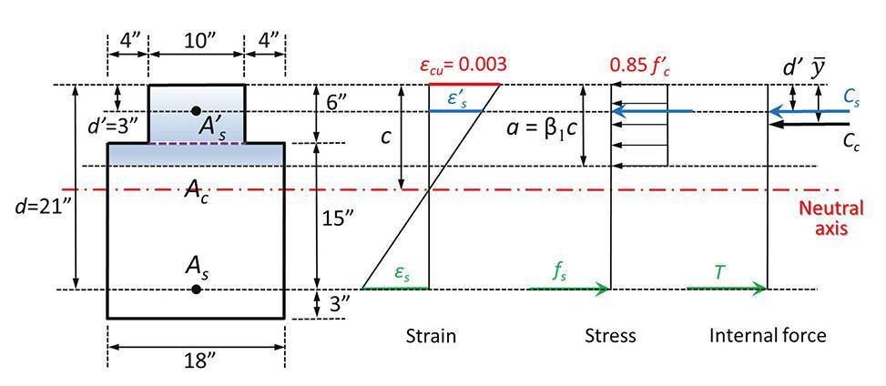
a. As = 4.0 square inches (in2) (4 #9 bars), A' s =0; calculate ��Mn ;
b. A' s = 0. Determine the lower and upper bounds of steel area As and ��Mn for a singly reinforced beam section according to ACI 318-19;
c. As = 3.6 in2 (6 #7 bars), A' s =0.62 in2 (2 #5 bars); calculate ��Mn


a. As = 4.0 in2 (4 #9 bars), A' s =0; calculate ��Mn
1. Perform forward analysis. Assume rebars yield:
2. (Shape) Ac =60+18(α-6), so (in)
3.
4.Verify assumption. The strain in the rebars rebars yield
5a. (Shape) centroid of Ac from top of section
6a. Flexural strength
Mn =As fy (d–y)=4.0 in2×60 ksi×(21.0-4.44) in=3,974 kips-inches (k-in)=331 kips-feet (k-ft)

7a. Strain in the extreme (bottom) layer of tension steel
��t =��s =0.00378
It is a transition section,
0.793
8a. ��Mn =0.793×331=262 k-ft
b. A' s =0. Determine the lower and upper bounds of steel area As and ��Mn for a singly reinforced beam section according to ACI 318-19
Determine the minimum steel area, As,min , according to ACI 318-19: 9.6.1.2:
Perform forward analysis using As,min

1. Assume rebars yield,
2. (Shape) Ac =10α, so α =2.97 in
3.
4. Verify assumption. The strain in the rebars rebars yield
5a. (Shape) centroid of Ac from top of section
6a. Flexural strength
Mn,max =As,min fy (d–y)=1.26 in2×60 ksi×(21.0-1.47)in=1,476 k-in=123 k-ft

7a. Strain in the extreme (bottom) layer of tension steel
��t = ��s =0.0151 > ��y +0.003=0.005
It is a tension-controlled section, �� =0.9
8a. �� Mn,min =0.9×123=111 k-ft
Determine the maximum steel area, As,max , according to ACI 318-19: 9.3.3.1, based on backward analysis.
1. Based on the strain diagram
2. α=��1c =0.85×7.875 in=6.69 in > 6.0 in
3. (Shape) Ac =60+18(α-6)=60+18(6.69-6) in2=72.42 in2

4. Since ��s =��t =0.005 > ��y =0.00207, rebars yield

5a. (Shape) centroid of Ac from top of section
6a. Flexural strength
M
n,max =As fy (d–y)=3.08 in2×60 ksi×(21.0-3.57)in = 3,221 k-in = 268 k-ft

7a. Strain in the extreme (bottom) layer of tension steel
��t =0.005
It is a tension-controlled section, �� =0.9


8a. �� Mn,max=0.9×268=241 k-ft
So the range of steel area permitted by ACI 318-19 is 1.26 in2 – 3.08 in2, and the corresponding moment strength range is 111 k-ft – 241 k-ft. However, the design (4 #9 bars) in Part a is not in this range since it is not a tension-controlled section, as seen in Figure 6.
c. As =3.6 in2 (6 #7 bars), A' s =0.62 in2 (2 #5 bars); calculate ��Mn


1. Assume both tension and compression rebars yield:
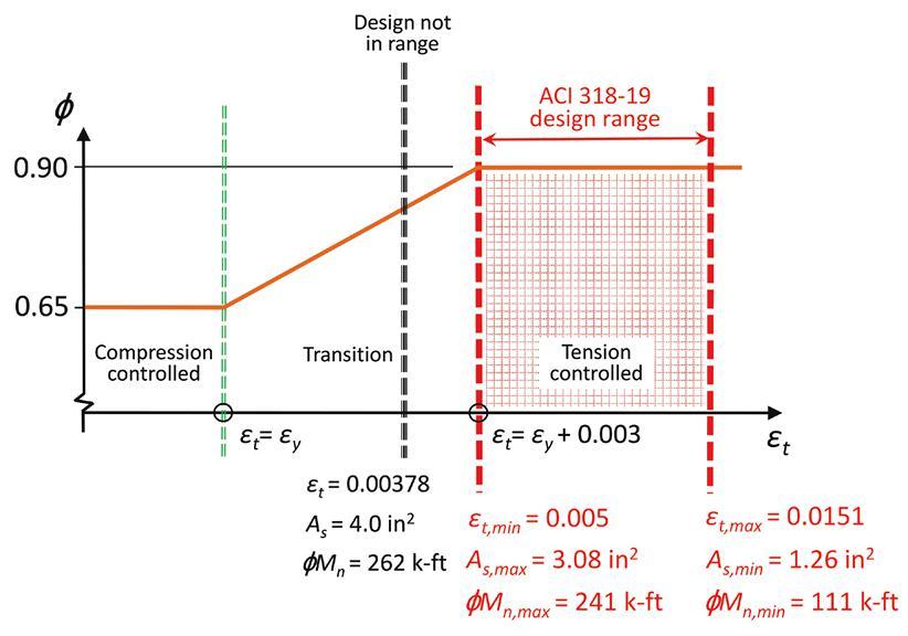
2. (Shape)
3.
4. Verify the two assumptions. Calculate the strain in both rebars
5b.Derive and solve an equation of c using the equilibrium equation

As fy =0.85f' c Ac +A' s f' s
A
c =60+18(α-6)=60+18(��1c-6)
Solve the quadratic equation of c,
c=7.82 in
6b. α= ��1c=0.85×7.82 in=6.65 in >6.0 in
7b.Calculate the strain and stress in the rebars
f' s =Es �� ' s =29,000 ksi×0.00185=53.62 ksi
8b.(Shape) Ac =60+18(α-6)=60+18(6.65-6)in2=71.7in

9b.(Shape) centroid of Ac from top of section
10b. Flexural strength
11b. Strain in the extreme (bottom) layer of tension steel
��t = ��s =0.0051
It is a tension-controlled section, �� =0.9
12b. �� Mn =0.9×316=284 k-ft
structural METHODS
Code-Checking Concrete Discontinuities
It has never been easier!
By Lukas Bobek, M.Sc., and Petra Komarkova, M.Sc.The design and assessment of concrete elements are typically performed at the sectional (1-D element) or point (2-D element) level. This procedure is described in all structural design standards, e.g., the American Concrete Institute’s ACI 318-19, Building Code Requirements for Structural Concrete and Commentary, EN 1992-11, Eurocode 2: Design of Concrete Structures, or the International Federation for Structural Concrete (fib) Model Code. All of these standards are used in everyday structural engineering practice. However, it is not always understood that the procedure is only acceptable in areas where the Bernoulli-Navieri hypothesis of plane strain distribution applies (referred to as B-regions). The places where this hypothesis does not apply are called discontinuity or disturbed regions (D-Regions). Examples of B and D regions of 1-D elements are shown in Figure 1 These include bearing areas, parts where concentrated loads are applied, locations where an abrupt change in the cross-section occurs, openings, etc. In addition, designers meet a lot of other D-Regions, such as walls, bridge diaphragms, corbels, etc., when designing concrete structures.
In the past, semi-empirical design rules were used for dimensioning discontinuity regions. Fortunately, these rules have been largely superseded over the past decades by Strut-and-Tie (S&T) models and stress fields, featured in current design codes and frequently used by designers today. These models are mechanically consistent and powerful tools. Note that stress fields can generally be continuous or discontinuous and that strut-and-tie models are a special case of discontinuous stress fields.
Despite the evolution of computational tools over the past decades, Strut-and-Tie models are primarily used as hand calculations. Consequently, their application for real-world structures is tedious and time-consuming since iterations are required, and several load cases need to be considered. Furthermore, this method is unsuitable for verifying serviceability criteria (deformations, crack widths, etc.).
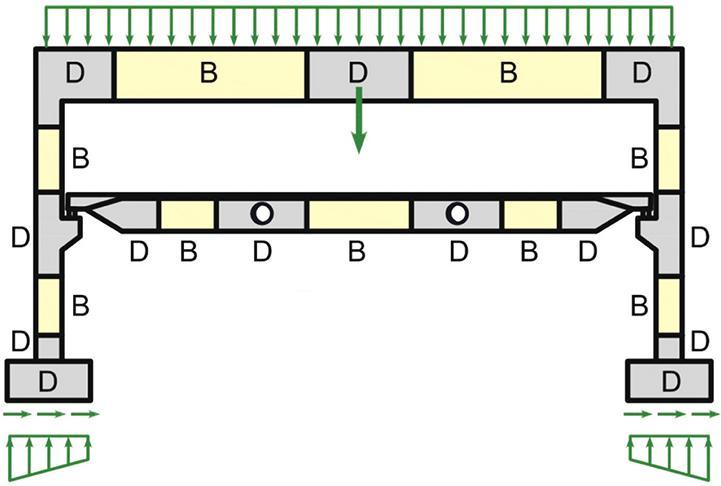
Why use a nonlinear solution for discontinuity regions? First, a general solution for walls with openings does not exist in the design codes. The creation of the S&T model must respect the fact, among others, that the tensile strength of the concrete is negligible. Therefore, if concrete is attributed with the ability to transfer just the compressive forces and steel with the ability to transfer only the tensile forces, the result is a very simple truss model consisting of elements exclusively under tension or compression. The strut and tie model must express the behavior of the structure in the limit state. The creation of the model thus cannot be accidental, but it must correspond to the conditions of the lower
bound and upper bound theorems. The impact of rebar positions on the mode of failure and crack propagation is demonstrated in the example in Figure 2
Engineers often use the linear-elastic 2-D model to determine stress flow into the wall to better predict the S&T geometry. Sometimes the results obtained from the linear-elastic analysis are directly used for the code check. However, structural behavior obtained from nonlinear analysis might differ from linear-elastic analysis (Figure 3). The cracks in the reinforced structure cause stiffness changes, leading to stress redistribution in a structural volume. Linear analysis often overestimates stresses in concrete. Stress peaks calculated by linear elastic analysis are smoothed thanks to nonlinear plastic material models defined by design codes, which correspond to real structural behavior.
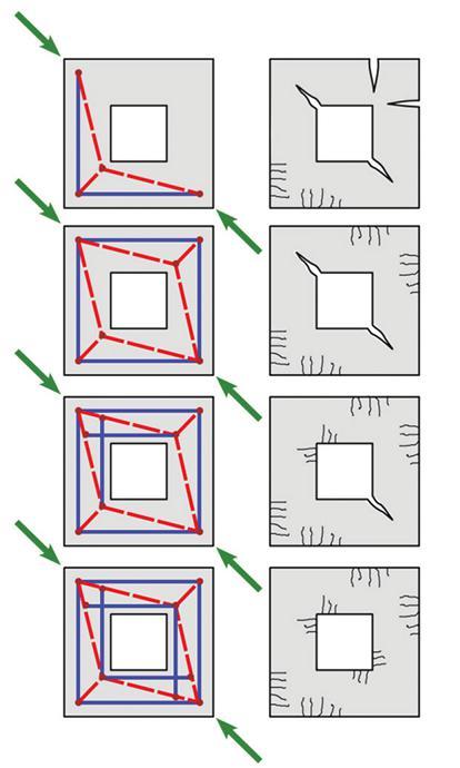
The Compatible Stress Field Method
The interest of structural engineers in a reliable and fast tool to design D-regions led to the development of the new Compatible Stress Field Method (implemented in IDEA StatiCa Detail), a computer-aided stress field design method that allows the automatic design and assessment of structural concrete members subjected to in-plane loading.
The Compatible Stress Field Method (CSFM) is a 2-D continuous finite element (FE)-based stress field analysis method in which classic stress field solutions are
complemented with kinematic considerations, i.e., the state of strain is evaluated throughout the structure. Hence, the effective compressive strength of concrete can be automatically computed based on the state of transverse strain in a similar manner as in compression field analyses that account for compression softening and the elastic-plastic stress field (EPSF) method. Moreover, the CSFM considers tension stiffening, providing realistic stiffnesses to the elements, and covers all design code prescriptions (including serviceability and deformation capacity aspects) not consistently addressed by previous approaches.
The CSFM uses common uniaxial constitutive laws provided by design standards for concrete and reinforcement. These are known at the design stage, allowing load and strength reduction factors to be used. Hence, designers do not have to provide additional, often arbitrary material properties as are typically required for nonlinear finite element analyses, making the method perfectly suitable for engineering practice.
The finite element model is composed of several types of finite elements (Figure 4):
•1-D reinforcement element,
•2-D concrete element,
•Special 2-D bond element,
• Rigid body and interpolation constraints (Multi-Point Constraints, MPC) between elements.
The last two are used for bond modeling. Furthermore, the latter enables the concrete and reinforcement finite element mesh to be created independently. The first type consists of two-node rod elements for which only axial stiffness is considered. The second type consists of four-node and three-node isoparametric flat plate elements considering a plane state of stresses. The Newton-Raphson algorithm is used to solve the set of nonlinear equations.
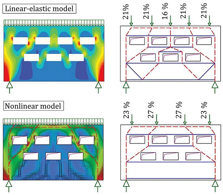
The CSFM assumes fictitious, rotating, stress-free cracks that open without slip (Figure 5a) and considers the equilibrium at the cracks together with the average strains of the reinforcement. Hence, the model considers maximum concrete (σc3r) (Figure 5b) and reinforcement stresses (σ sr) (Figure 5d) at the cracks while neglecting the concrete tensile strength (σc1r = 0), except for its stiffening effect on the reinforcement. The consideration of tension stiffening allows the average reinforcement strains (ε m) to be simulated (Figure 5c).
Despite their simplicity, similar assumptions have been demonstrated to yield accurate predictions for reinforced members subjected to inplane loading if the provided reinforcement avoids brittle failures at cracking. Furthermore, the non-consideration of any contribution of the tensile strength of concrete to the ultimate load is consistent with the principles of modern design codes, which are mainly based on plasticity theory.
However, the CSFM is not suited for slender elements without transverse reinforcement since relevant mechanisms for such elements
as aggregate interlock, residual tensile stresses at the crack tip, and dowel action – all of them relying directly or indirectly on the tensile strength of the concrete – are disregarded. While some design standards allow the design of such elements based on semi-empirical provisions, the CSFM is not intended for this potentially brittle structure.
An advantage of nonlinear analysis is the ability to calculate serviceability limit states such as crack width and deflection. The reduction of crack width protects reinforcement against corrosion and extends the structure’s lifetime. The serviceability analysis contains certain simplifications of the constitutive models used for ultimate limit state analysis. The plastic branch of the stress-strain curve of concrete in compression is disregarded, while the elastic branch is linear and infinite. Compression softening law is not considered. These simplifications enhance the numerical stability and calculation speed and do not reduce the generality of the solution as long as the resultant material stress limits at serviceability are clearly below their yielding points (as required by design codes). Therefore, the simplified models used for serviceability are only valid if all verification requirements are fulfilled.
Due to concrete creep, the long-term effects of the deflection must be considered. Reducing the modulus of elasticity of the concrete reduces the stiffness of the structure, which leads to a redistribution of stresses in the element and an increase in deformation (Figure 6).
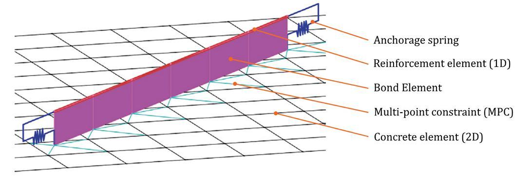
Practical Examples
Walls with Openings
Concrete walls and deep beams are common load-bearing elements in building structures. However, these bearing structures are very often weakened by openings for piping, doors, window, and more.
When designing complex
structures, engineers commonly create global models in 3-D analysis programs, from which the internal forces are used to design the individual structural elements. As an example, consider a wall with a door opening. The wall is 9.75 feet (3.0m) high, 18.5 feet (5.7m) wide, 12 inches (0.3m) thick, and is located in the basement of a multistory residential building and founded on piles. The loads on each edge of the wall are taken from a global model created by Scia Engineer (Figure 7).
CSFM includes tools such as Linear Analysis or Topology Optimization based on finite element calculations. Based on the geometry of the structure and the selected loads, the areas of the wall most subjected to compression and tension are determined, serving as a guide for the design of the reinforcement.
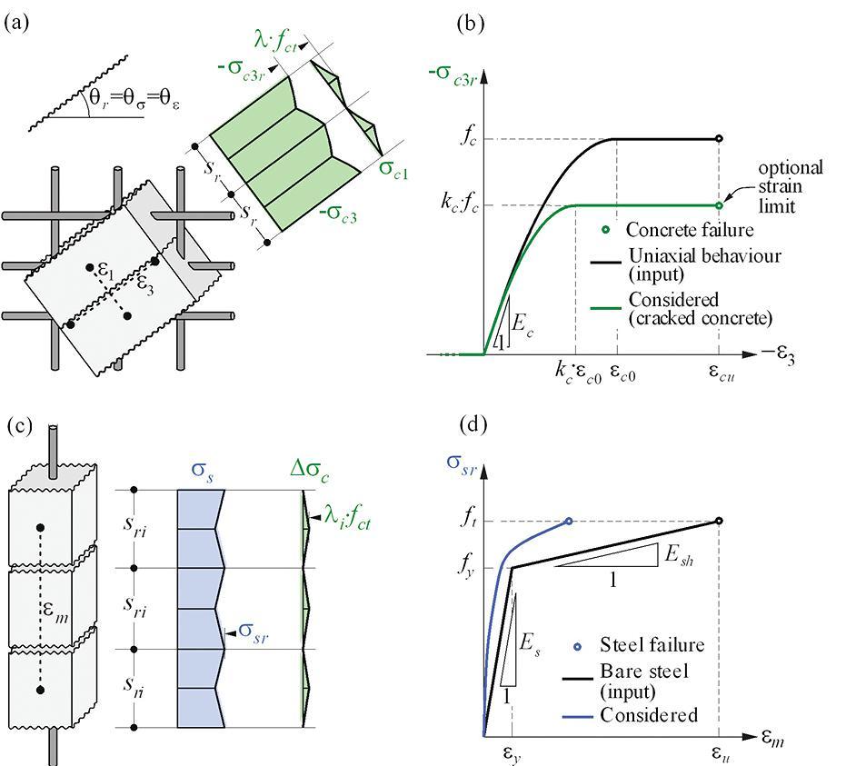
When defining the reinforcement, reinforcing bars need to be added around the door opening. Significant tensile stresses are often generated at the corners of the opening, so it is appropriate to insert inclined reinforcing bars to prevent wide cracks.
The calculation results in the stress assessment in both concrete and reinforcement for the ultimate limit state. The most significant stress in the concrete occurs at the top of the wall. Due to the pile bearing, wall deformation causes bending in the vertical direction. In addition, the inclined concrete compression strut in the left part of the wall causes large transverse tensile strains resulting in wide cracks and, at the same time, a reduction in the compressive strength of the concrete in this area.
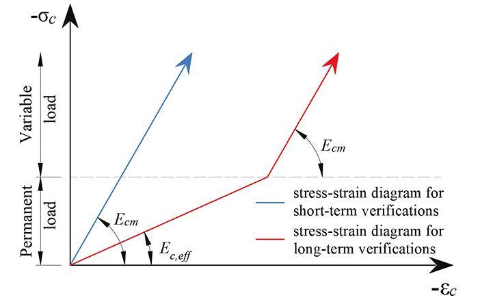
Corbels (Brackets)
In industrial buildings, a common structural element is a corbel (bracket) that transmits high intensities of shear force and bending moment from the horizontal structure (beam) to the column. Such stresses cause a complex load transfer in the relatively small volume of the reinforced concrete element, resulting in a nonlinear behavior of the individual stress components. The geometry of S&T models defined in design standards such as ACI 318-19 or EN 1992-1-1 can be used to design a new structure. The disadvantage is that only the ultimate load capacity of the cantilever can be determined using these models without knowledge of the deformation behavior of the structure. Furthermore, the absence of a crack width check can lead to unsafe design if the corbel is placed in the aggressive environment of a production hall and corrosion of the reinforcement occurs after the formation of wide cracks. Many engineering structures used for production purposes (factories, warehouses) were built decades ago. Due to the influence of time, material degradation, and increased demands on the structure due to increased production, individual parts of the structures do not meet the requirements for their safe use. For example, engineers designed corbels in the last century according to beam theory, leading to inappropriate shear reinforcement layout design. Today, methods of strengthening corbels based on post-tensioning are known. However, existing S&T models cannot adequately capture the effect of prestressing on the structure. Using the nonlinear CFSM method can capture not only the actual deformation behavior of the structure at ultimate and serviceability limit states but also check the width of the cracks developed and thus ensure the structure’s durability (Figure 8).
Conclusion
Structural analysis and design of concrete structures is a challenging task – both because of the natural complexity of the subject and because of the regulation an engineer has to comply with to get the project done. Limit analysis methods, in general, and Strut-and-Tie models and stress fields, in particular, are powerful tools for designing concrete structures. They are transparent, allow one to trace the flow of forces, and give the engineer control over the design. However, they are typically used as
hand calculations, making their application tedious and time-consuming since iterations are required and several load cases need to be considered. In addition, they are not directly applicable for checking serviceability criteria, and the influence of prestressing is challenging to capture. The construction process has never been as fast as it is today, and the pressure on the cost-effectiveness of structures is growing with zero tolerance for structural defects. In such an environment, engineers are pushed to work quicker, more accurately, and reliably than ever. And they need a different set of tools for that. The development trend of computing software should provide engineers with a generic, complete, and easyto-use solution for designing and code-checking structural elements, cross-sections, and details following applicable standards. Complete code-checks for ultimate and serviceability limit states (including crack widths calculation) allow engineers to sleep peacefully
Acknowledgment
This paper and its research would not have been possible without the cooperation of the Swiss Federal Institute of Technology

(ETH) Zurich. Professor Walter Kaufmann, the Chair of Structural Engineering (Concrete Structures and Bridge Design), and his research team focus on the load-deformation behavior of structural concrete, the structural safety evaluation of existing bridges and buildings, innovative structures and bridges, as well as interdisciplinary research projects. They have done exceptional work validating and verifying the CSFM method and securing code-compliancy with design codes.■
Full references are included in the online version of the article at STRUCTUREmag.org
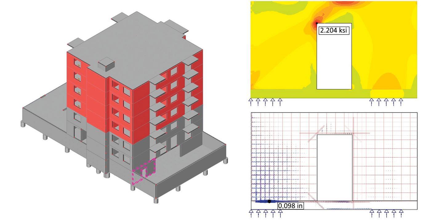
Lukas Bobek is PhD civil engineering student whose passion is to design concrete structures, especially bridges (lukas.bobek@vutbr.cz).
Petra Komarkova is an experienced civil engineer, currently working as Product Engineer with IDEA StatiCa (petra.komarkova@ideastatica.com).
structural SPECIFICATIONS
Non-Metallic Reinforcement for Concrete
What Structural Engineers Should Know About GFRP Reinforcement
By Aparna Deshmukh, Ph.D., William J. Gold, P.E., Gusai H. AlAithan, and Antonio Nanni, P.E.In steel-reinforced concrete (steel-RC) structures, reinforcing steels corrosion reduces the structure’s lifespan and requires expensive repairs. When steel-RC structures are exposed to moisture coupled with chlorides and CO2, concrete deterioration is caused, leading to significant repairs typically after 25 years of service. As the structure ages, major repairs can be expected every ten years until it needs to be replaced, typically after 50 to 75 years of continuous service. Researchers and engineers have been studying corrosion in concrete structures and exploring ways to prevent it. The use of Fiber Reinforced Polymer (FRP) reinforcing bars was considered in the early 1960s as one potential solution for preventing corrosion in reinforced con-crete. There was a significant development in FRP research, field demonstrations, and commercialization starting in the 1980s and continuing since then.
As with any new construction technology or building material being developed, it is critical to have building codes for these materials to ensure safe and resilient structures. Over the last few decades, there have been industry consensus design guidelines for FRP-reinforced concrete. ACI PRC-440.1R Guide for the Design and Construction of Structural Concrete Reinforced with Fiber-Reinforced Polymer Bars was first published in 2001. ACI PRC-440.1R describes many unique aspects and design considerations for FRP-reinforced concrete that are widely used within the industry; however, it is a non-mandatory guideline. As research and applications of FRP-reinforced concrete have advanced, there has been an increasing need for standards and codes for this technology that can be directly referenced and adopted by other building codes.
In 2017, ASTM D7957, Standard Specification for Solid Round Glass Fiber Reinforced Polymer Bars for Concrete Reinforcement, was introduced as a material specification covering Glass Fiber Reinforced Polymer (GFRP) bars. The GFRP bars covered by this specification must meet the minimum requirements for geometry, material, mechanical, and physical properties. In 2008, ACI published a standard construction specification for FRP-reinforced concrete that was recently updated in 2022. ACI SPEC 440.5-22, Construction with Glass Fiber-Reinforced Polymer Reinforcing Bars, provides mandatory language construc-tion requirements that project specifications can directly reference. In September 2022, ACI published ACI 440.11-22, Building Code Requirements for Structural Concrete Reinforced with Glass Fiber-Reinforced Polymer (GFRP) Bars. With the publication of this code, there are now a complete set of codes and standards that allow engineers to confi-dently and safely specify and design FRP-RC structures. Notably, these codes and standards all center around Glass FRP (GFRP) bars. ASTM material standards for other FRP bars and ACI design standards for the respective bars may be developed in the future.
What are FRP Reinforcing Bars?
In concrete structures, FRPs are an alternative to steel reinforcement. They are composite materials made of fibers embedded in polymeric
resins (Figure 1). The non-magnetic and non-corrosive nature of FRP materials allows them to be used as reinforcement without encountering problems of electromagnetic interference or steel corrosion. Furthermore, FRP materials exhibit characteristics such as high tensile strength that are suitable for reinforcing structures.
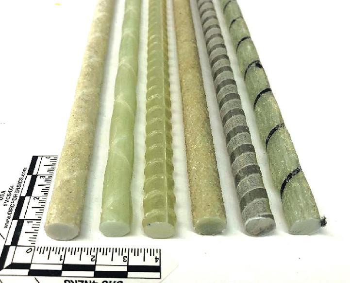
As reported in ACI 440.1R-15, the mechanical behavior of FRP reinforcement differs from the behavior of conventional steel reinforcement. Accordingly, a change in the traditional design philosophy of RC structures is needed for FRP reinforcement. Fiber-reinforced polymer materials are anisotropic and are characterized by high tensile strength only in the direction of the reinforcing fibers. This anisotropic behavior affects the shear strength and dowel action of FRP bars and the bond performance. Additionally, FRP materials do not yield; they are elastic until failure. Design procedures should account for the lack of ductility in structural concrete members reinforced with FRP bars. The stress-strain relationship of various reinforcing systems is demonstrated in Figure 2.
Benefits and Uses
First, one of the main benefits of FRP reinforcing bars is that they do not corrode. This has led to the use of FRP reinforcing bars as an alternative to steel reinforcing bars in applications where corrosion of reinforcing steel is a significant concern. For example, these might include: a) Marine structures that are directly exposed to chloride-laden seawater; b) Coastal buildings and infrastructure that are exposed to airborne chlorides from nearby seawater bodies; c) Bridge decks and pavements exposed to high levels of aggressive deicing salts; d) Parking garages exposed to vehicles carrying deicing salts; e) Highly corrosive industrial applications.
Next, FRP is a high-strength, lightweight material with a unit density of ⅓ to ¼ that of mild steel. For example, a #5 GFRP bar weighs approximately 0.30 pounds/ lineal foot, whereas a #5 steel reinforcing bar weighs 1.04 pounds/lineal foot. The lighter weight of GFRP reinforcing bars may reduce transportation costs and labor cost and provides easy handling.
In addition, GFRP reinforcing bars are relatively easy to cut using a circular saw with a carborundum blade. Reciprocating saws with metal cutting blades can also be used (torches or shearing-type tools such as bolt cutters should never be used to cut FRP bars). These bars are cut quicker and with far less effort than steel bars which can speed up and ease the installation process. Finally, FRP reinforcing bars are nonmetallic and non-magnetic and have benefits in certain applications involving exposure to elec-tromagnetic fields. For example, using steel reinforcement around equipment that generates magnetic fields can disrupt the operation of the equipment. Similarly, equipment that generates high current may induce high heat in adjacent steel reinforcement, reducing its structural capacity. In these applications, non-metallic reinforcement becomes a necessary component of the safe and effective operation of the equipment. These applications may include areas around magnetic resonance imaging (MRI) units in hospitals, magnetic levitating (maglev) trains, and reactors in power plants. GFRP bars are electrically non-conductive and have low thermal conductivity. Therefore, they have been used in applications where thermal bridging needs to be avoided.
Material Properties of GFRP Bar
The GFRP reinforcing bars consist of fibers that contribute to mechanical strength, resin that helps transfer or distribute stress from one fiber to another to protect the fiber against environmental and mechanical damage, and fillers that reduce cost and shrinkage. The interface between the fiber and matrix significantly affects the performance of GFRP composites. Moreover, factors such as fiber volume, fiber type, resin type, fiber orientation, dimensional effects, and quality control during manufacturing play a critical role in defining the characteristics of a GFRP bar.
The volume fraction is the ratio of the volume of fibers in a composite to the overall volume of the composite material. The higher volume fractions, typically ranging from 70% to 80%, yield higher tensile properties. Similarly, the orientation of the fiber plays an essential role in governing the mechanical and other properties, such as the coefficient of thermal expansion (CTE), thermal conductivity, and electrical conductivity of GFRP bars. The fiber orientation can be aligned with principal stress directions to optimize performance and accommodate applied loads. Orienting the fibers along the length of the bar results in high strength and stiffness along the length but relatively lower strength and stiffness in the transverse direction. This explains lower shear strength, bond strength, and lower level of dowel action in the reinforcing GFRP bars compared to steel bars.
Mechanical Properties
1) Tensile Properties – As shown in Figure 2, the tensile behavior of the GFRP bar is characterized as linear elastic up to failure. FRP bars’ tensile strength varies with the bar8 size, while the longitudinal modulus does not exhibit notable change. Larger bar diameters generally have lower net tensile strength because the outer fibers of the bar are more highly stressed than the inner fibers of the bar when loaded in tension (and bonded to concrete). ACI 440.11 uses a property referred to as the guaranteed ultimate tensile strength as specified in ASTM D7957. ASTM D7957 provides a table of the minimum tensile force for GFRP bars with a range of values depending on the bar size. For example, the minimum tensile force for a ¼-inch-diameter (No. 2) bar is 6.1 kips which translates to 125 ksi, whereas the minimum strength of an 11¼-inch-diameter (No. 10) bar is 98.2-kips which translates to 77-ksi.
2) Compressive Properties – Compressive strength and stiffness of GFRP materials can be significant but typically not as high as the material’s tensile strength and stiffness. ACI 440.11 design criteria assume that FRP bars have the same compressive modulus as concrete and provide equivalent compressive resistance.
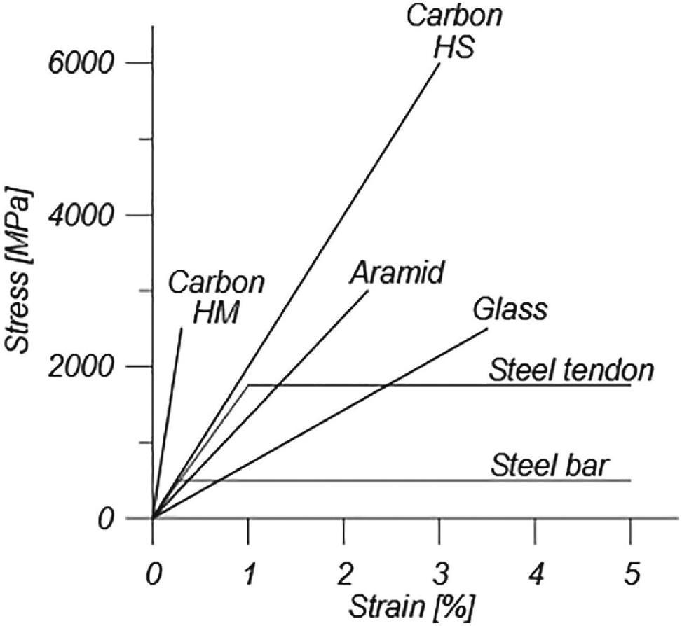
3) Shear Strength – The shear strength of GFRP bars is generally lower than comparably sized steel bars due to the anisotropic nature of GFRP bars. ACI 440.11 provides for a lower shear contribution of the concrete (Vc) based on testing of GFRPreinforced concrete beams and may be in part due to the lower dowel action of the steel bars. ACI 440.11 does not cover using FRP bars or dowels across an interface to transfer shear.
4)Bond Strength – FRP bars intended for concrete reinforcement generally have surface treatments that allow for bonding to
con-crete. These can be sand coatings, deformations such as helically wound fibers that indent the bar’s surface, or protrusions or lugs machined into the bar’s surface. (There are other FRP bars used with concrete that do not use surface treatments, such as GFRP dowel bars and GFRP bars embedded in epoxy used for strengthening existing structures. Those types of reinforcements are outside the scope of ACI 440.11.) GFRP bars conforming to ASTM D7957 must have an appropriate surface treatment and a guaranteed bond strength of at least 1,100-psi to concrete when tested per ASTM D7913, Standard Test Method for Bond Strength of Fiber-Reinforced Polymer Matrix Composite Bars to Concrete by Pullout Testing. ASTM D7913 is a bond pull-out test similar to what is used to characterize the bond strength of steel bars.
5) Strength at Bends – FRP bars cannot be field bent due to their linearly elastic behavior. However, bars are commonly produced with 90° bends by bar manufacturers. Bends larger than 90° are not generally available; since FRP bars do not plastically bend in use, larger bend angles do not improve
performance. In addition, the bend radii the fibers must follow to allow such bends result in a lower tensile strength at bend locations. ASTM D7957 requires the tensile strength of the bent portion of a bar to be at least 60% of the strength of the straight bar.
Thermal Properties
1)The coefficient of thermal expansion (CTE) of FRP materials can vary directionally depending on the fiber orientation. Typically, the polymers in FRP materials have a relatively high CTE, and the fibers have a relatively low CTE (aramid and carbon fibers can have negative CTE values). In the direction of the fibers, the lower CTE of the fibers restrains the overall composite CTE. In directions perpendicular to fibers, the CTE remains rather large with no restraint provided by the fibers. The Table shows typical ranges of CTE for various FRP reinforcing bars in the longitudinal and transverse directions. The CTE of GFRP and BFRP bars in the longitudinal direction are similar to the CTE of concrete and steel reinforcement. There is the potential for the difference in CTE to cause splitting crack-ing under large temperature changes, especially for larger bar sizes. However, these effects have not been observed in any field installations.
2) Glass Transition Temperature – The polymer component of FRP materials softens under moderately high heat. At elevated temperatures, the polymer rapidly transitions from a glassy material to a rubbery material, and the FRP material rapidly loses strength and stiffness. The glass transition temperature, Tg, of FRP materials is the average temperature
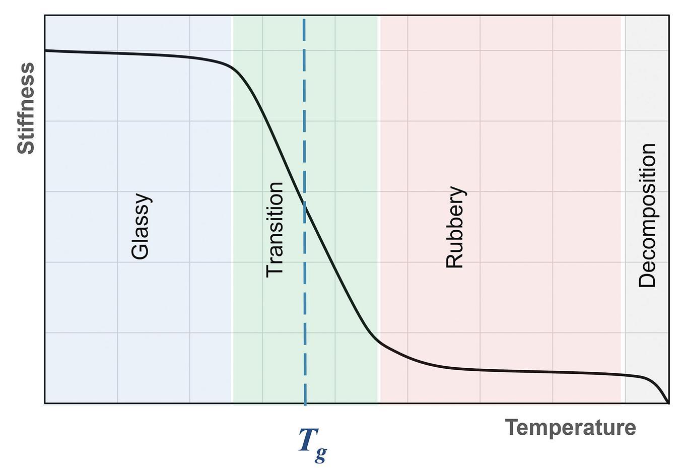
over which it transitions from a rigid, glassy material to a rubbery material. The transition occurs rapidly over a small temperature change, as shown in Figure 3. It is important to note that the transition to a rubbery material is an irreversible change for thermosetting polymers typically used in FRP reinforcing bars. Most commer-cially available FRP bars constructed using vinyl ester polymers have a glass transition temperature near 250°F. ASTM D7957 requires a minimum glass transition temperature of 212°F tested per ASTM E1356.
Durability Properties
1) Corrosion – FRP materials are inherently non-corrosive. In cor-rosive environments, it is not necessary to use specific concrete properties that may be required with steel-reinforced concrete. Notably, ACI 440.11 Table 19.3.1 does not use Exposure Category C (Corrosion Protection of Reinforcement) that exists in ACI 318 Table 19.3.1. It is anticipated that the service life of FRP reinforcing bars is greater than steel in certain corrosive environments.
2) Accelerated Aging – Accelerated aging studies of FRP bars have shown reductions in tensile strength (but not modulus) under exposure to certain environments. ASTM D7957 provides requirements on moisture absorption and retention of properties after exposure to elevated temperatures and alkalinity to ensure the durability performance expected with GFRP bars. And ACI 440.11 utilizes an environmental reduction factor, CE, to account for the loss of strength over time. The CE value is applied to the guaranteed tensile strength and bends’ guaranteed strength to arrive at the design values for these properties. CE is defined as 0.85 by ACI 440.11 Section 20.2.2.3.
3) Creep Rupture – FRP materials, in general, are susceptible to a phenomenon known as creep rupture or static fatigue. When the material is loaded in sustained tension, the creep of the material results in higher induced strain. If the strain levels from creep become large enough, the material can suddenly experi-ence tensile failure/rupture. To avoid this failure mode, ACI 440.11 Section 24.6.2 limits the sustained stress in the GFRP reinforcing bars to 30% of their design ultimate tensile strength. The material’s resistance to creep rupture greatly depends on the type of fibers.
What ACI 440.11-22 Includes
ANSI-certified ACI 440.11-22 specifies minimum requirements for building materials, design, and detailing of structural buildings and non-building structures reinforced with GFRP bars that comply with ASTM D7957-22. This Code mirrors ACI 318-19, Building Code Requirements for Structural Concrete and Commentary. It includes design and construction for strength, serviceability, and durability; load combinations, load factors, and strength reduction factors; structural analysis methods; deflection limits; development and splicing of reinforcement; construction document information; field inspection and testing; and methods to evaluate the strength of existing structures. In addition, it provides design provisions for beams, one-way and two-way slabs, columns, walls, foundations, and connec-tions between members. Furthermore, the code explains differences in design between GFRP- reinforced concrete and steel-reinforced concrete
in the commentary. FRP reinforcement behaves differently than steel reinforcement, so merely replacing steel reinforcement with the same size and spacing is inadequate. For instance, GFRP bars do not yield and exhibit linear elasticity until failure. ACI 440 addresses this difference and approaches design from the perspective of deform-ability, in contrast to steel reinforcement, which emphasizes ductility. Additionally, GFRP bars possess high tensile strength only in the direc-tion of the reinforcing fibers, affecting shear strength, dowel action, and bond performance. As a result, the equations for shear strength and development length in ACI 440.11 are different from those for steel reinforcement, even though the design procedures are similar.
Fire resistance of FRP RC structures is an important consideration. The Commentary to ACI 440.11 provides guidelines for establishing the fire ratings of FRP RC elements. However, this topic needs to be developed further, and the code currently limits the use of FRP reinforcement to structures that do not require a fire rating unless the building official approves an approach that establishes a fire rating.
Several topics are not covered in the current version of the Code but are expected to be covered in future editions. These include seismic provisions, diaphragms, anchorage to concrete, strut-and-tie methods, prestressed construction, lightweight concrete, shotcrete, connections of precast members, deep beams, drilled piers and caissons, brackets and corbels, and shear friction. Additionally, it does not cover the design of hybrid members with mixed steel and FRP reinforcement, but this is also envisioned for future code editions.
NEx Workshops and Other Educational Resources
NEx is an ACI center of excellence for non-metallics in building materials. It is actively educating engineers on the newly developed ACI CODE 440.11-22 and the application of GFRP reinforced concrete by organizing workshops and seminars and developing manuals for the use of this code. For the latest update, please visit nonmetallic.org or email us at info@nonmetallic.org. ■
Full references are included in the online version of the article at STRUCTUREmag.org.
Aparna Deshmukh is a Technical Director of NEx: An ACI Center of Excellence for Nonmetallic Building Materials. She manages the technical and educational efforts, development of special engineering or educational products, and reviews technical documents.
William J. Gold is an Engineer with the American Concrete Institute. He has over 25 years of practical experience using FRP material systems. He uses that experience to disseminate knowledge on these systems and other technologies.
Gusai H. AlAithan is an Engineer with Saudi Aramco. He is currently working with NEx to support the utilization of non-metallic materials in building and construction.
Antonio Nanni is a Professor at the University of Miami. He currently serves as ACI Vice President. His research in materials and structures has impacted the work of technical committees in the U.S. and abroad, including agencies such as AASHTO, ACI, ASCE, ASTM, and ICC-ES.
CODES and STANDARDS
FAQ on SEI Standards
What you always wanted to ask.
By Laura Champion, P.E., F.SEI, F.ASCE and Jennifer Goupil, P.E., F.SEI, M.ASCEThis quarterly article addresses some of the questions received about structural standards developed by the Structural Engineering Institute (SEI) of the American Society of Civil Engineers (ASCE). In addition, questions from engineers, building officials, and other design professionals are often considered in the development of future editions of the Standards. Following are some questions received along with SEI’s responses .
Seismic Site Effects
ASCE 7-22 Chapter 11 is missing
Table 11.4.1 for Short Period Site Coefficients, Fa , and Table 11.4.2 for Long Period Site Coefficients, Fv . Is this a huge typo?
No, it is not a typo. These coefficients are intentionally removed because they are no longer needed. In ASCE 7-22, the risk-targeted maximum considered earthquake (MCER) spectral response acceleration parameters SS, S1, SMS, and SM1 are required to be obtained directly from the United States Geological Survey (USGS) Seismic Design Geodatabase for the applicable site class. And, because the values are now included in the database for all site classes directly, the coefficients formerly used to calculate the spectral response acceleration parameters for short periods (SMS) and at 1 second (SM1), adjusted for site class effects, no longer need to be calculated.
The ASCE 7-22 Chapter 11 Commentary provides a more detailed explanation. While the theoretical basis for MCER ground motions has not changed from ASCE 7-16 (and prior editions), ASCE 7-22 now uses multi-period response spectra (MPRS) to improve the accuracy of the frequency content of earthquake design ground motions and enhance the reliability of the seismic design parameters derived from these ground motions. These improvements make better use of the available earth science, which has in general, sufficiently advanced to accurately define spectral response for different site conditions
ASCE/SEI 7: Minimum Design Loads and Associated Criteria for Buildings and Other Structures
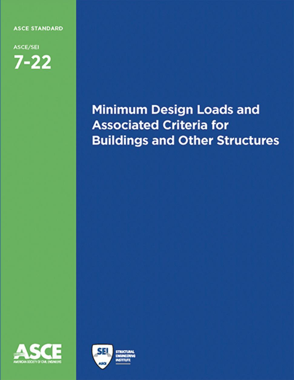
over a broad range of periods and eliminate the need for sitespecific hazard analysis required by ASCE 7-16 for certain (soft soil) sites.
The following brief history explains why these were used for one cycle of ASCE 7 in the 2016 edition.
During the closing months of the 2015 cycle of the Provisions Update Committee (PUC) of the Building Seismic Safety Council, a study was undertaken of the compatibility of current
Site Class coefficients F a and F v, with the ground motion relations used by USGS to produce the design maps. In the course of this study, it was discovered that the standard three-domain spectral shape defined by the short-period response spectral acceleration parameter, SDS, the 1-second response spectral acceleration parameter, SD1, and the long-period transition period, TL, is not appropriate for soft soil sites (Site Class D or softer), in particular, where ground motion hazard is dominated by large magnitude events. Specifically, on such sites, the standard spectral shape substantially understates spectral demand for moderately long period structures. The PUC initiated a proposal to move to specification of spectral acceleration values over a range of periods, abandoning the present three-domain format, as this would provide better definition of likely ground motion demands. However, this proposal was ultimately not adopted due to both the complexity of implementing such a revision in the design procedure and time constraints. Instead, the PUC adopted a proposal prohibiting the general use of the three-parameter spectrum, and instead requiring site-specific hazard determination for longer period structures on soft soil sites.
Subsequently, Project 17 (NIBS 2019) was charged with re-evaluating the use of multiperiod response spectra as a replacement or supplement to the present three-domain spectral definition and to consider how the basic design procedures embedded in ASCE 7 should be modified for compatibility with the multi-period spectra. As a result, Project 17 developed (and unanimously approved) a comprehensive multi-period response spectra (MPRS) proposal that was subsequently adopted (with changes) in the 2020 National Earthquake Hazards Reduction Program (NEHRP) Recommended Seismic Provisions for New Buildings and Other Structures, which form the basis for related changes to ASCE 7-22.
Furthermore, “mapped” values of seismic parameters SS, S1, SMS, and SM1 are archived in the USGS Seismic Design Geodatabase at gridded locations across United States regions of interest and provided online by the USGS Seismic Design Web Service for user-specified site location (latitude and longitude) and site class. The USGS web service spatially interpolates between the gridded values of these parameters based on site location (latitude and longitude). Chapter 22 provides print copies of seismic parameters SMS and SM1 for default site conditions. Seismic parameters SMS and SM1 (and SDS and SD1) incorporate site effects, eliminating the need for the tables of site factors F a and F v of ASCE 7-16.
User Note: The USGS Seismic Design Geodatabase is intended to be accessed through a USGS Seismic Design Web Service that allows the user to specify the site location, by latitude and longitude, and the site class to obtain the seismic design data. The USGS web service spatially interpolates between the gridded data of the USGS geodatabase. Both the USGS geodatabase and the USGS web service can be accessed at https://doi.org/10.5066/ F7NK3C76. The USGS Seismic Design Geodatabase is available at the ASCE 7 Hazard Tool https://asce7hazardtool.online/ or an approved equivalent.
New Reliability-Targeted Ground Snow
In reviewing the ground snow in ASCE -22, the values look very different than what we have been using in my
jurisdiction from past editions of ASCE 7. How do the new ground snow zones compare to the previous zones or Tables in 7-16?
This is correct. The ground snow included in ASCE 7-2 is very different from the values calculated in the past editions, and these are no longer zone maps. The adoption of reliabilitytargeted design ground snow loads in the ASCE 7-22 standard represents a significant change from ASCE/SEI 7-16 and prior editions, which previously used ground snow loads with a 50-year mean recurrence interval (MRI). Reliability-targeted loads are adopted here to address the nonuniform reliability of roofs designed according to the 50-year snow load in different parts of the country due to climatic differences. In some parts of the country, designing for the 1.6 load factor times the 50-year value does not meet the reliability targets of the standard (and, in some of these places, failures due to an underestimated ground snow load have been observed). In other places, designing for the 1.6 load factor times the 50-year value is unnecessarily conservative. With the move to reliability-targeted values, the load factor on snow loads has also been revised from 1.6 to 1.0 to represent the reliability basis of the values appropriately. Snow importance factors have also been eliminated because values are now provided for each risk category. The 0.7 factor is intended to provide roughly equivalent strength when the design follows Allowable Stress Design (ASD) procedures. For some materials, the ratio between design strength given by LRFD procedures and design strength given by ASD procedures is 1.5. For some other materials, the ratio varies depending on the limit state being checked. The inverse of 1.5 was rounded to 0.7 for this purpose. Also, note that the 2024 International Building Code and International Residential Code have updated provisions to accommodate this change. ■
This article’s information is provided for general informational purposes only and is not intended in any fashion to be a substitute for professional consultation. Information provided does not constitute a formal interpretation of the standard. Under no circumstances does ASCE/SEI, its affiliates, officers, directors, employees, or volunteers warrant the completeness, accuracy, or relevancy of any information or advice provided herein or its usefulness for any particular purpose. ASCE/SEI, its affiliates, officers, directors, employees, and volunteers expressly disclaim any and all responsibility for any liability, loss, or damage that you may cause or incur in reliance on any information or advice provided herein.
If you have a question you want to be considered in a future issue, send it to sei@asce.org with FAQ in the subject line. Visit asce.org/sei to learn more about ASCE/SEI Standards.
historic STRUCTURES
Burlington Bridge, 1868
19th Century Mississippi River Bridges Series
By Frank Griggs, Jr., Dist. M.ASCE, D.Eng,. P.E., P.L.S.The Chicago, Burlington & Quincy
Railroad started very small in 1849 with lines around Chicago and points to the southwest. By 1864, it had extended its lines southwesterly to the east bank of the Mississippi River, opposite Burlington, Iowa. A car ferry carried the train across the river where it connected with the Burlington and Missouri Railroad that had been incorporated in 1852 and expanded westerly, reaching the Missouri River by January 1, 1870. Congress approved a bridge across the river in the July 25, 1866, Act regarding bridges across the Mississippi. Section four of the Act stated,
“And be it further enacted, That it shall be lawful for the Chicago, Burlington, and Quincy Railroad Company, a corporation whose road has been completed to the Mississippi River, and connects with railroad on the opposite side thereof, having first obtained authority therefor from the States of Illinois and Iowa, to construct a railroad bridge across said river, upon the same terms, in the same manner, under the same restrictions, and with the same privileges, as is provided for in this act in relation to the bridge at Quincy, Illinois.
The channel of the river for 5,000 feet above the bridge and 3,000 feet below runs along the west bank in a direction for the most part parallel with the shore, which is rocky. The bluffs rise abruptly from the shore except at the site of the town, which is in an opening in the bluffs through which Hawkeye Creek flows. The river for two miles above and one below the bridge is confined to one channel, in which there is always a good navigable depth.”
The Chief Engineer was Max Hjortsberg, who started his surveys for a bridge as early as 1865 and determined that a bridge setting on piles was possible rather than the more expensive use of pneumatic caissons that were to be used by James Eads at St. Louis. Hjortsbert was born in Sweden. After working in England for a time, he emigrated to the United States in 1852. In 1854, he was named Chief Engineer for the Chicago, Burlington & Quincy Railroad. He located his bridge in the winter when the river was covered with ice, so direct measurements were possible rather than the need to resort to triangulation methods. A low-level bridge was the only type available for this site, given the low level of the land on the eastern bank of the river. That being the case, he
had to meet the requirements of the 1866 Act for a low-level bridge that stated,
“That if any bridge built under this act shall be constructed as a drawbridge, the same shall be constructed as a pivot drawbridge with a channel draw over the main channel of the river at an accessible and navigable point, and with spans of not less than one hundred and sixty feet in length in the clear on each side of the central or pivot pier of the draw, and the next adjoining spans to the draw shall not be less than two hundred and fifty feet; and said spans shall not be less than thirty feet above low-water mark, and not less than ten above extreme high-water mark, measuring to the bottom chord of the bridge, and the piers of said bridge shall be parallel with the current the river.”
As seen by the plan, the line originally ended its track at a depot on the eastern Bank, where the cars would be loaded on a car ferry to the Iowa Shore. The selected bridge site was located about a mile to the south, where the river was narrower. The line had a sweeping curve to the right up to the river, then a bridge at right angles to the river, followed by a sweeping curve to the right and a new station at Burlington. The line then turned to the west through an opening in the bluff. The bridge, as laid out by Hjortsberg from the west to east, was described by G. K. Warren,
“The bridge is approached from the west on an embankment
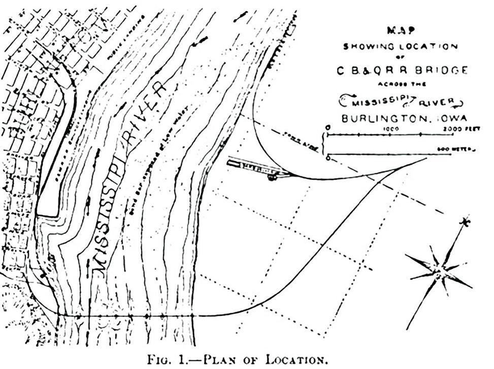
with a curve of about 720 feet radius. The first span is 175 feet long from center of abutment to center of first pier-part of the span being over the land. The second span is 200 feet long. The trusses of these two spans are wider than those of the rest of the bridge to allow the curve of the approach to be extended on the bridge. The next span is a pivot draw 360 feet long overall, with two clear openings of 160 feet each; then there are 6 spans of 250 feet each from centers, and then trestling for a few hundred feet.”
The placing of the foundations was very innovative. It consisted first of driving wood piles and then cutting them off 1 to 5 feet below the original river bottom. This was followed by jetting away the sand around the pile tops and replacing it with crushed stone up to the level of the cutoff pile. Then the tops of the piles were covered with two layers of 12- x 12-inch timbers bolted together. Next, a wooden caisson, also built of 12- x 12-inch timbers, was floated into place. Masonry was then laid inside the wooden caisson, sinking it to a depth of 2 to 3 feet above the timber mat. Holes were drilled into the side of the caisson below the water level; the water that poured in sank the caisson onto the mat. Once the caisson was aligned properly with good bearing on the mat, the masonry was built up to a level above water, and the timber caisson’s sides were removed to be used again. George Morison, in discussing the Bridge, later stated, “One of the greatest features of the Burlington Bridge, as originally built, and as described by Mr. Hudson, the feature that has done more than any other to facilitate the building of bridges across the Mississippi, is the fact that they succeeded in doing work underwater without working underwater.”
As was then customary, Hjortsberg prepared a set of specifications and preliminary plans and sent them out to bridge Companies asking for their proposals and cost estimates. The Detroit Bridge & Iron Company was also building the Quincy Bridge just downstream and was awarded the contract for the superstructure. They proposed Whipple Double Intersection trusses for their fixed spans and a variation of the Whipple truss for the swing span. The top chords were cast iron, as were all the junction blocks, and the vertical posts were Phoenix Columns of wrought iron. The double panel diagonals and lower chord members were wrought iron loop bars. The swing span was operated by a steam engine mounted above the tracks
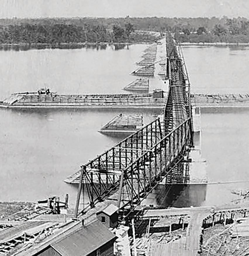
and over the turntable.
Foundation work on the project began in January 1867, but due to ice and flooding, not much was done until March 1868. The last pier was finished for the swing span on March 3, 1868. The erection of the superstructure was very fast. On August 14, 1868, newspapers reported, “The iron railroad bridge, which has been in the process of construction across the Mississippi at Burlington since February 1867, by the Chicago, Burlington & Quincy Railroad Company, at a cost of over $1,500,000, was today tested, and pronounced completed. The first train passed over from Illinois to Iowa at 3:15 p. m….The successful transfer was honored with a salute of twelve guns and other manifestations of rejoicing.”
The bridge was test loaded on August 13, 1868, and witnessed by a select panel of engineers. Their report on the following day indicated that a load of 180 tons on the 250-foot span had a deflection of less than 2½ inches, and, when the load was removed, it returned close to its original position. Moving loads gave about the same deflection. The same load was applied to the swing span and gave deflections of less than a half inch. They also reported, “The draw was opened and closed, by hand power, several times for the passage of steamboats, while we were there, and once for our particular inspection, when it was opened in 31/2 minutes, and closed in a little over 4 minutes.”
Hjorftsberg wrote several years later, “all these works have been constructed to my entire satisfaction with respect to character of materials and workmanship.” What Hjorftsberg and the Detroit Bridge & Iron Company had done was to design and build the first all-iron bridge across the Mississippi River. In 1893, a two-track bridge by George Morison replaced the 1868 bridge. The new bridge has a swing span of 356 feet 6 inches, six 246-foot-long fixed spans, and two 70-foot plate girder spans opened for service. In 2011, the bridge was replaced with a 370-foot-long lift span, five fixed spans, and two plate girder spans.■
Awards Season is just starting at NCSEA and We Don’t Want You to Miss It!
Call for Submissions for the 2023 Structural Engineering Excellence (SEE) Awards

Would you like to see your firm’s prized project on the list of winners for the 2023 Structural Engineering Excellence (SEE) Awards program?
The SEE Awards highlight structural engineering ingenuity in the world and incredible achievements in the profession. Structural engineers and firms are encouraged to enter their projects to highlight their successes and accomplishments. Projects are judged on innovative design, engineering achievement, and creativity.
Winning projects will also receive significant promotional benefits, including a poster board presentation at the Awards Celebration, coverage in STRUCTURE magazine and NCSEA media outlets, the opportunity to present in the annual awards webinar series, and more.
Categories include:
• New Buildings < $30 Million
• New Buildings $30 Million to $80 Million
• New Buildings Over $200 Million


• Forensic/Renovation/Retrofit/Rehabilitation Structures < $20 Million
• Forensic/Renovation/Retrofit/Rehabilitation Structures > $20 Million
• New Bridges or Transportation Structures

• Other Structures
Visit www.weseeaboveandbeyond.com/see-awards for more information and to submit your project.
Deadline for submissions is June 5, 2023.
Winners will be announced at the Awards Celebration at the Structural Engineering Summit on November 9, 2023, at the Disneyland Hotel in Anaheim, California.

Call for Nominations for the 2023 Special Awards
Do you know a fellow engineer who has contributed exemplary service and commitment to the betterment of the structural engineering profession? NCSEA is now accepting nominations for the 2023 Special Awards including:
• NCSEA Service Award
• Robert Cornforth Award
• Susan M. Frey Educator Award
• Susan Ann “Susie” Jorgensen Presidential Leadership Award
• James Delahay Award
Special Award honorees will be announced in advance of the Summit via NCSEA and STRUCTURE media outlets and celebrated at the Awards Celebration at the Structural Engineering Summit on November 9, 2023, at the Disneyland Hotel in Anaheim, California.
Visit http://www.ncsea.com/awards/specialawards/ for more information and to submit your project.
Deadline for submissions is June 5, 2023.
News from the National Council of Structural Engineers Associations
Call for Entries for the 2023 Young Member Group of the Year Award
Each year at the NCSEA Structural Engineering Summit, an award is given to recognize an outstanding Young Member Group (YMG) from one of the Structural Engineering Associations (SEAs). The emphasis of this award is to acknowledge Young Member Groups that are providing a benefit to their young members, SEAs, and communities.
Finalists will receive complimentary registration to send a representative to the Structural Engineering Summit. Finalist groups also will receive a $1,000 travel stipend to use toward transportation and hotel costs. (Winning recipients will only receive the travel stipend for attending the Summit).
The winning Young Member Group will be announced at the Summit and will receive an additional $2,500 for their Young Member Group to use for future activities.
Entries must be submitted by June 30, 2023. Visit www.ncsea.com/awards/ymgchapter/ for more information and to submit an entry.
The 2023 Young Member Group of the Year Award is generously sponsored by Computers & Structures, Inc.
Call for Submissions for the 2023 Young Member Summit Scholarships
NCSEA is once again offering scholarships to young members to cover the costs of attending the 2023 Structural Engineering Summit being held on November 7 –10, 2023, at the Disneyland Hotel in Anaheim, California.

First-time scholarship recipients will receive complimentary registration to the Summit which includes all educational sessions, access to the trade show, and an invitation to the NCSEA Awards Celebration, as well as a travel stipend of $1,000 to use toward transportation and hotel costs. Previous scholarship recipients will receive complimentary registration to the Summit.
To qualify for a scholarship, the applicant must be:
• Under 36 years of age
• A current member of an NCSEA Member Organization (SEA)

Applications must be submitted by June 30, 2023. For more information and to submit an application, visit http://www.ncsea.com/awards/ymawards
The 2023 Young Member Scholarships are generously sponsored by Computers & Structures, Inc.
NCSEA Webinars
April 20, 2023
April 25, 2023
May 2, 2023
May 11, 2023
The Hidden Cost of"Copy & Paste"Engineering
Eccentrically Braced Frames
Visit www.ncsea.com/education for the
Reinforced Concrete Ductile Coupled Walls and Seismic Design of Concrete Walls: SEAOC Seismic Design Manual Volume III, Examples 1 & 2
New Buildings $30 Million to $80 Million: Idaho Central Credit Union Arena
Purchase an NCSEA webinar subscription and get access to all the educational content you'll ever need! Subscribers receive access to a full year's worth of live NCSEA education webinars (25+) and a recorded library of past webinars (170+) – all developed by leading experts; available whenever, wherever you need them!
View webinar on Transition of PE Structural Engineering Exam to Computer Based Testing
Brought to you by the Structural Engineering Licensure Coalition (CASE, NCSEA, SEI), NCEES Chief Officer of Examinations Jason J. Gamble, P.E., provides a brief history of the PE Structural Exam, presents its new format, compares it to the existing format, and responds to participant questions. www.youtube.com/channel/UCLPU58f1yUxzOatcKBNokUQ
Now available for free download: Prestandard for Performance-Based Wind Design V1.1
Presents recommended alternatives to the prescriptive procedures for wind design of buildings contained in the nationally adopted standard Minimum Design Loads and Associated Criteria for Buildings and Other Structures (ASCE 7) and in the International Building Code (IBC). ascelibrary.org/doi/book/10.1061/9780784484739
Turkey Earthquake Collection Procurement of Peer Review Services for Complex Bridge Design Projects: Recommended Procedures
In response to the 7.8 magnitude earthquake that struck southeastern Turkey and northwestern Syria, ASCE Library has opened papers to help structural engineers understand the vulnerabilities of buildings, and better mitigate damage. Open to registered ASCE Library users through 4/30/2023. ascelibrary.org/turkey_earthquake
Provides a concise outline for accomplishing independent peer reviews for bridge design projects in the United States. ascelibrary.org/doi/book/10.1061/9780784484616
Anchor Sponsor
RegistrationOpenNow
Registration Open Now
Engage,network,andlearnwiththecommunityaswe worktogethertoadvancethestructuralengineering professionforabetterfuture.
structurescongress.org
Arrive early to Structures Congress and join us for: ASCE 7 Forum



Wednesday, May 3, 4-5:30pm at Hyatt Regency New Orleans
The forum will provide an overview of changes in the 2022 edition of ASCE 7 and related updates to the 2024 I-Codes. It will also cover topics being considered for the 2028 cycle, including serviceability and future conditions. The interactive forum will include audience participation and a comparison to national survey results. (Non PDH program)
Additional information in technical program at www.structurescongress.org/program
Congrats to SEI Futures Fund Student Scholarship Recipients
to Structures Congress
Qozeem Abiona, University of Delaware

Gabriel Ackall, Georgia Institute of Technology
Seth Anderson, Clarkson University
Sheila Ariana, University of Massachusetts

Amherst
Joseph Cortas, University of Cincinnati

Saransh Dikshit, Iowa State University
Akash Doshi, Stanford University
Naia Echevarria, Purdue University

Mohamed Elshazli, University of Idaho


Liam Johnson, Michigan Technological University


Kate Kemnitz, Syracuse University
Steven Kontra, Oregon State University
Cole Landes, United States Air Force Academy
Samantha Leonard, Penn State University

Hugh Merryday, Auburn University
Sandra Milev, University of Delaware
Musawer Ahmad Saqif, University of Michigan

Judy Too, University of Manchester
Alexis Tri, United States Air Force Academy
Omar Yadak, The University of Oklahoma
Give to the SEI Futures Fund and multiply your gift with the 3 to 1 CSI Matching Gift Challenge


As a donor to the SEI Futures Fund, you are supporting the future of structural engineering, promoting student interest, aiding younger-member involvement, and ensuring opportunities for professional development. Help us maximize the full impact of the CSI match opportunity and give a gift today!
THANK YOU, SEI FUTURES FUND DONORS!
Thank you to all those that generously support the SEI Futures Fund. Your gifts fund SEI strategic initiatives – exceeding $250,000 in FY23. View donor list and learn more at www.asce.org/SEIFuturesFund
2022 Donors
FOUNDERS
John L. & Karen E. Carrato
Jon D. Magnusson
JAMES LAURIE VISIONARY CIRCLE
John L. & Karen E. Carrato
Jon D. Magnusson
Sarmad (Sam) & Ina Rihani
Odeh Engineers, Inc.
LEGACY SOCIETY
Phillip L. Gould
Silky S. K. Wong
SUSTAINERS
Jennifer Goupil
Julian J. Lineham
J. Greg Soules
Silky S. Wong
2022 ANNUAL GIFT SUPPORT
PHILANTHROPIST SOCIETY
$10,000+
Structural Engineering Certification Board
CHAMPION SOCIETY
$5,000-9,999
David & Monica Biggs
Severud Associates Consulting Engineers


GUARDIAN SOCIETY
$2,500-4,999
James R. Harris
LEADER SOCIETY
$1,000-2,499
Cary H. Beatisula
Glenn and Judy Bell
Joseph G. Burns
John L. & Karen E. Carrato
Edward M. and Mary F. DePaola and Family
Thomas A. DiBlasi
Robin A. Kemper & Family
Otto J. Lynch
Jon D. Magnusson
Sarmad (Sam) and Ina Rihani
Jon A. Schmidt
Donald R. Scott
J. Greg Soules
Silky S. K. Wong
The Charles Pankow Foundation
SUPPORTER CLUB
$500-999
Robert E. Bachman
Laura E. Champion
John Cleary
Gregory T. Holbrook
John G. Tawresey
Victor E. Van Santen
Beverly M. & Loring A. Wyllie, Jr. Odeh Engineers, Inc.
FRIEND CLUB
$250-499
Randall P. Bernhardt
Eric W. Borchers
Robb A. Dibble
W. Samuel Easterling
Bruce R. Ellingwood
Bora Erbilen
Roberto T. Leon
Ivan Ramirez
Dennis & Nancy Tewksbury
William H. Thorpe
Paul Z. Zia
DONOR CLUB
$100-249
Aimee Corn
Gregory F. Force
Phillip. L. Gould
Jennifer Goupil
John O. Grieshaber
Patti Harburg-Petrich
Thomas F. Heausler
Andrew W. Herrmann
Takahiko Kimura
Peter L. Lee
Marc L. Levitan
Julian J. B. Lineham
David H. MacDonald
Satish Nagarajaiah
Jeffrey L. Stapleton
Mehdi S. Zarghamee
Anonymous (3)
$1-99
Rogelio N. Alama
Prodyot K. Basu
H. Edmund Bergeron
Karl F. Hees
Linda M. Kaplan

Sher A. Mirza
Heather C. Neri

Andre Newinski
Jean-Paul Pinelli
Bradford O. Russell

Nitesh Sangam
Shamsher B. Singh
Anonymous
CASE in Point
Tools To Help Your Business Grow...
If you are a member of CASE this tool and all publications are free to you. NCSEA and SEI members receive a discount on publications. Use discount code - NCSEASEI2022 when you check out.
Beyond the Code: Grade-Level Floors over Expansive Soils — CASE recognizes that the International Building Code or other governing codes do not address all aspects of structural engineering and design. Often, the most common issues where the owners, or the contractor or the design team are not aligned deal with what is not clearly addressed by the various codes or design guidelines. This is the first in a series of “Beyond the Code” white papers that will attempt to collate design considerations that need to be discussed with the owners at the beginning of a project to establish a clear Basis-of-Design for the project. By proactively bringing up the design consideration in front of the owners, the Structural Engineer can set up realistic expectations and discuss the cost impact of alternative designs. This first white paper in the “Beyond the Code” series will discuss the pros and cons between two structural design options for the grade level floor in expansive soil regions. Keep an eye out for future installments in the series!

What’s Shaking?
A new publication from CASE about Seismic Design
CASE Guideline 962- J Ð Business Practice Guidelines of Seismic Design for the Structural Engineer. The purpose of this document is to provide insights about structural engineering services in regions where there is a seismic hazard. This document shares key design considerations as well as business practice considerations. Numerous resources are available that provide a much more exhaustive and advanced technical presentation of important considerations when designing for earthquakes. Someone new to designing for earthquakes should consider taking a course in structural dynamics and seismic engineering whether from a university or some other provider such as ASCE or NCSEA.
You can purchase these and other Risk Management Tools at www.acec.org/bookstore
You can also browse all of the CASE publications at www.acec.org/coalitions/coalition-publications/ Is there something missing for your business practice? CASE is committed to publishing the right tools for you. Have an idea? We’d love to hear from you!
Upcoming Events
Trends in Decarbonization
March 21, 2023
Online Course
Join the Coalition of American Mechanical and Electrical Engineers (CAMEE) for a broad look at decarbonization beyond specific systems and equipment, as we consider buildings holistically. We will evaluate design choices across the entire building, as well as the importance of building operations. Attendees of this session will gain insight into industry trends and their implications for buildings, the greening of the grid, regulations, and what is practical over the next 15 years.


Find the course here: https://tinyurl.com/4cbyhh7x
Follow ACEC Coalitions on LinkedIn: www.linkedin.com/in/acec-coalitions


Upcoming Events
The Secrets to Small Firm Success: How to Lead Your Firm Forward in this New Era
April 3- May 15, 2023
Online Course
Like most large-scale systemic events, March 2020 gave ‘official birth’ to a new era of work and life – one with new rules, new ways of thinking, and lots of big change. The changes we continue to see and experience in the workplace, marketplace, and recruiting space are both fundamental and generational. Our biggest opportunities for new and continued growth and success are dependent on our ability to understand, navigate, and leverage this change.
Although this is true for all firms, the opportunity is especially great for smaller firms. Time is of the essence, however, if you’d like to take advantage of the differences only you as a small firm can offer.
Register now for The Secrets to Small Firm Success: How to Lead Your Firm

Forward in this New Era and learn the steps, strategies, skills, and mindset needed to understand and leverage the fact that ‘bigger isn’t always better’, better is better!
Earn up to 12 PDHs and build a more powerful peer-to-peer leader network!
https://program.acec.org/small-firm-coalition-workshop
About the CASE Committees...
Do you know someone in your firm that is looking for ways to expand and strengthen their business skillset, gain experience serving on a committee, sharpen their leadership skills, and travel to interesting places? Please consider applying for a position on the committee.
Committee member commitments include a monthly virtual meeting, a few hours a month working on relevant documents, and travel to the Coalitions winter and summer meetings!
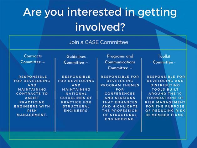
To apply, your firm should:
•Be a current member of ACEC
•Be a member of the Coalition of American Structural Engineers (CASE); or be willing to join the Coalition

•Be able to attend the groups' normal face-to-face meetings each year: August, February (hotel, travel partially reimbursable)
• Be available to engage with the committees via email and video/conference call
•Have some specific experience and/or expertise to contribute to the group
Now more than ever we need to support the upcoming generation of the workforce.
Tips for Hiring Entry-Level Structural Engineers
By Joseph Yamin, P.E.Have you heard the story of how Thomas Edison screened potential new research assistants? Legend has it that he would invite applicants out for a meal and order soup for the table. As the story goes, he did this to see how the applicants approached the situation. Did they make assumptions about the blandness and season the soup before tasting it, or did they allow themselves to taste it first and decide afterward if seasoning was necessary? Edison’s purpose was to weed out those who seasoned before tasting, reasoning that those who relied on assumptions would not produce the kind of open-minded Scientists and Engineers he needed in his laboratory. The lesson from this tale is to think about how best to evaluate a candidate for a potential position on your team. Design schedules are becoming increasingly accelerated, and competition is compressing fees. These two forces are putting tremendous pressure on design staff, and it is more important than ever to ensure the young engineers you are hiring are productive team members. As the leader, it is your job to select candidates with the skills (both hard and soft) to be effective engineers who can learn from experience as they advance in their careers. The author has used the following practices successfully and are recommended as a best practices approach
Determining if a new graduate candidate has the required minimum hard skills needed for an entry-level position is not something that can be gleaned from reviewing a resume or asking general questions in a standard interview format. Instead, it requires digging a bit deeper. The first recommendation is to review a copy of the candidate’s transcripts before the interview, evaluating what classes a student chose to take and how well they performed. A degree and graduation year on a resume does not offer much information besides that they graduated. However, seeing the student’s transcript gives you more insight. Did they take a relevant number of structural engineering classes? Was there a good mix of analysis and design? How well did they do – average or above average? In addition, you should see relevant classes that reinforce the necessary soft skills desired in practice, such as technical writing and a drafting class. This recommendation helps frame the candidates’ backgrounds beyond the cursory information in their resumes. As a future Professional Engineer, the class selection and performance lend insight into their skills and the seriousness of their passion for their chosen profession. This should be
the first step in evaluating a candidate before the interview.
Once you have decided that the candidate may be a good fit, it is time to bring them in for an interview. During the interview, this is your opportunity to observe and assess their soft skills. How do they carry themselves in a professional environment? What is their communication ability (speaking and writing)? How do they interact with others? As the saying goes, half of a Structural Engineer’s job involves design, and the other half is communicating our design. One useful assessment exercise is to bring the candidate around to see the office and meet other employees. Observe how they interact with their potential teammates or leaders. Are they communicative? Do they seem interested and genuinely thoughtful in asking questions about the office environment, current projects, etc.? Not only do you see how the candidate interacts, but it also allows others within your firm to interact with the candidate. While this interaction may be brief, your current employees may form important opinions about the candidate’s ability to fit within the current team. While this should not be the only consideration, your employees’ opinions are an important metric to consider.

By this point in the process, you should start to form an opinion on whether a candidate is a good fit. If this is the case, it is recommended that one final technical assessment is performed – the interview quiz. This has shown to be, by far, the best way to assess the knowledge of a potential graduate. In addition, the quiz removes any potential implicit bias you or those in your firm involved in the hiring process may have towards a candidate. Finally, it provides an objective assessment of skills, which best indicates a candidate’s potential ability. Therefore, the quiz should be developed to probe areas of knowledge deemed relevant to the position and confirm a candidate’s grasp of fundamental structural mechanics. Questions should be tailored to your specific needs, but, generally, for an entry-level position, the following are recommended:
1)Statics and structural analysis (i.e., determine reactions and draw the shear and moment diagrams for a specific beam loading);
2)Load path fundamentals/understanding;
3)Steel design (i.e., sketch a simple shear connection);
4)Concrete design (i.e., indicate where the tension reinforcement would be placed in this frame system).
The quiz should be kept to a reasonable length (less than 45 minutes to complete) and not require a calculator. Besides the answers, hopefully correct ones, the quiz also provides insight into how the candidate thinks and their writing and sketching ability (the importance of soft skills and communication). Additionally, the quiz reveals how they deal with pressure – presumably, this was not something they expected or prepared for when they came in for the interview.
In summary, these recommendations are best practices for evaluating candidates for entry-level structural engineering positions to introduce quantitative metrics into the hiring process. The goal is to minimize potential biases and successfully hire a candidate with the skills necessary to be a productive team member. These approaches may be new, but it is certainly worth considering adding them to your interview process. Of course, once you have found the right candidate and they have accepted your employment offer, be sure to take them out to lunch for soup to celebrate!■
RESOURCES for Building Code Officials
News
The ACI Building Officials Webinar Series will focus on highlighted topics specifically for building officials that have been approved for professional development hours from the International Code Council (ICC). Additional programs in the ACI Building Officials Webinar Series will continue throughout 2023.
Upcoming Live Webinars
•Sustainability – Julie Buffenbarger
•Drainage/Waterproofing – Brent Anderson
On-Demand Courses
To view on demand courses, visit ACI University and click on the Redeem Code tab. Submit the access code ACICode to add the Building Official Webinar Series to your profile. Earn 1.0 PDH/0.1 CEU for each webinar by passing the 10-question quiz.
• Hot Weather Concrete – Tarek Khan
•Surface Imperfections in Concrete – George Seegebrecht
•Residential Concrete – Jim Baty
•Cold Weather Concrete – Kim Basham
•Concrete Basics – Michelle Wilson
