
CONCRETE INSIDE: Little Rock Art Museum 26 Berkeley’s Biosciences Hub 23 Tendon Tail Cutting 30 Drones in Practice 36 STRUCTURE NCSEA | CASE | SEI JANUARY 2023




Building AESTHETICS | ACOUSTICS | FLEXIBILITY | CONSTRUCTABILITY | SUSTAINABILITY
Successful building projects
the selection
the right steel building system supplier. With
of steel joists, joist girders and steel deck to help you achieve your goals, New Millennium is your supplier of choice. Together, let’s build it better. BUILDING SUCCESS TOGETHER LEARN MORE newmill.com
Collaboration gives rise to better steel structures
begin with
of
an extensive range
American Concrete Institute 4
ASDIP Structural Software 3
CTS Cement Manufacturing Corp 43
DCI Engineers 34
ENERCALC 6


Max USA Corp 28
Please support these advertisers
New Millennium Building Systems 2
Portland Cement Association 51
Simpson Strong-Tie 19
Structural Engineering Institute of ASCE 40-41
Computers & Structures, Inc 52
Welcoming 2023 with Two New Columns
Starting in January 2023, STRUCTURE will feature two new regularly occurring columns: Structural Influencers and Iconic Structures.
The Structural Influencers column highlights mostly current practicing structural engineers who have or had a significant impact on the profession, individuals that might inspire our readership. A celebration of the living, you might call it. No hard and fast attributes qualify a person for this prestigious recognition. But they will likely have had some or a combination of 1) longstanding and active participation in national professional organizations, 2) known for advancing the state of the practice technically through their engineering work, 3) recognized as a leader having high engineering ethics and skills, and 4) started and maintained a successful engineering practice. This is not intended to be a group of the Greatest of All Time; we will never agree on who those are. But rather, they have had careers that any of us would be proud to have had. Please see page 38 of this issue for the first Structural Influencers installment.
The Iconic Structures column highlights structures that are all around us (but maybe overlooked in our daily lives) and were state-of-the-art at the time they were built and may still be so today. Structures that employed technologies or designs far in advance for their time and are still worthy of learning from today. If you have ever looked at an old set of drawings and came away amazed at what the engineers accomplished with hand calculations and without advanced computer modeling, you will understand the kinds of structures we intend to highlight.
Best Wishes for the New Year!

 John Dal Pino, Chair, STRUCTURE Editorial Board
STRUCTURE®
MARKETING & ADVERTISING SALES

Director for Sales, Marketing & Business Development Monica Shripka Tel: 773-974-6561 monica.shripka@STRUCTUREmag.org
EDITORIAL STAFF
Executive Editor Alfred Spada aspada@ncsea.com
Publisher Christine M. Sloat, P.E. csloat@STRUCTUREmag.org
Associate Publisher Nikki Alger nalger@STRUCTUREmag.org
Creative Director Tara Smith graphics@STRUCTUREmag.org
EDITORIAL BOARD
Chair John A. Dal Pino, S.E. FTF Engineering, Inc., San Francisco, CA chair@STRUCTUREmag.org
Jeremy L. Achter, S.E., LEED AP ARW Engineers, Ogden, UT
Erin Conaway, P.E. AISC, Littleton, CO
Linda M. Kaplan, P.E. Pennoni, Pittsburgh, PA
Charles “Chuck” F. King, P.E. Urban Engineers of New York, New York, NY
Nicholas Lang, P.E. Masonry Industry Representative
Jessica Mandrick, P.E., S.E., LEED AP Gilsanz Murray Steficek, LLP, New York, NY
Jason McCool, P.E. Robbins Engineering Consultants, Little Rock, AR
Brian W. Miller Davis, CA
Evans Mountzouris, P.E. Retired, Milford, CT
John “Buddy” Showalter, P.E. International Code Council, Washington, DC Eytan Solomon, P.E., LEED AP Silman, New York, NY
Jeannette M. Torrents, P.E., S.E., LEED AP JVA, Inc., Boulder, CO
STRUCTURE ® magazine (ISSN 1536 4283) is published monthly by The National Council of Structural Engineers Associations (a nonprofit Association), 20 N. Wacker Drive, Suite 750, Chicago, IL 60606 312.649.4600. Periodical postage paid at Chicago, Il, and at additional mailing offices. STRUCTURE magazine, Volume 30, Number 1, © 2023 by The National Council of Structural Engineers Associations, all rights reserved. Subscription services, back issues and subscription information tel: 312-649-4600, or write to STRUCTURE magazine Circulation, 20 N. Wacker Drive, Suite 750, Chicago, IL 60606.The publication is distributed to members of The National Council of Structural Engineers Associations through a resolution to its bylaws, and to members of CASE and SEI paid by each organization as nominal price subscription for its members as a benefit of their membership. Yearly Subscription in USA $75; $40 For Students; Canada $90; $60 for Canadian Students; Foreign $135, $90 for foreign students. Editorial Office: Send editorial mail to: STRUCTURE magazine, Attn: Editorial, 20 N. Wacker Drive, Suite 750, Chicago, IL 60606. POSTMASTER: Send Address changes to STRUCTURE magazine, 20 N. Wacker Drive, Suite 750, Chicago, IL 60606.
STRUCTURE is a registered trademark of the National Council of Structural Engineers Associations (NCSEA). Articles may not be reproduced in whole or in part without the written permission of the publisher.
JANUARY 2023 3
ADVERTISER index
ADVERTISEMENT–For Advertiser Information, visit STRUCTUREmag.org
ACI 318 PLUS
SUBSCRIBE TODAY: An annual subscription that provides users with digital interactive access to ACI CODE-318-19, “Building Code Requirements for Structural Concrete and Commentary,” along with in document access to related resources and enhanced digital search features through all code provisions and commentary.

Includes full digital interactive access to the ACI Detailing Manual, the ACI Reinforced Concrete Design Handbook, and a new case study showing the connection between ACI CODE-318-19 and the structural calculations and drawings of a constructed reinforced concrete hotel. Subscribers can make digital notes alongside ACI CODE318-19 provisions and commentary, and navigate content by section, chapter, and/or by provision.
For access and to subscribe, visit www.concrete.org/ACI318.
Subscribe Today!
26 AN ICONIC STRUCTURE RISES IN LITTLE ROCK
By Ben Sexton P.E., S.E., and Faz Ehsan, Ph.D., P.E.
The reimagined Arkansas Museum of Fine Arts project’s centerpiece is a new concrete structure with folded plate roof. Shear walls and sloping columns support the folded plate roof structure. Challenges included developing a process to model the organic folded plate roof analytically so it could be easily modified as the design evolved and accounting for Little Rock’s moderate seismic zone location, which controlled the structure’s lateral design.

20 ONE STEP CLOSER TO NET-ZERO
By Scott Erickson, P.E., S.E., and Erin Spaulding
Fifteen Fifty and 49 South Van Ness stand – quite literally – at the center of San Francisco. The 16-story steel-framed office tower portion of the project (49 South Van Ness) is home to the City’s Department of Building Inspection, which set a high-performance standard for its new home: a Category III building to increase seismic resiliency. The SEOR opted to pursue a Performance-Based Design.
23 UC BERKELEY’S NEW BIOSCIENCES HUB
By
Allen Nudel, S.E., Masume Dana, S.E., and Andrew Salber, S.E.
In 2016, the California Institute for Quantitative Biosciences began a project to reuse the original Berkeley Art Museum building that the Museum left unoccupied due to seismic deficiencies exposed by the 1989 Loma Prieta earthquake. The new Biosciences Hub reuses the building as a full-service life sciences incubator. The transformation of this landmark building incorporated a seismic retrofit into a complicated space, preserved the historic structure, and more.
Publication of any article, image, or advertisement in STRUCTURE® magazine does not constitute endorsement by NCSEA, CASE, SEI, the Publisher, or the Editorial Board. Authors, contributors, and advertisers retain sole responsibility for the content of their submissions. STRUCTURE magazine is not a peer-reviewed publication. Readers are encouraged to do their due diligence through personal research on topics.
JANUARY 2023 5
Cover Feature
JANUARY 2023 Contents 7 Editorial All the Things I Did Not Learn in School By Jeff Morrison 8 Structural Design Post-Installed Rebar By Richard T. Morgan, P.E. 12 Structural Performance Coupled Composite Plate Shear Walls/Concrete-Filled By Soheil Shafaei, Ph.D., Amit H. Varma, Ph.D., and Ron Klemencic
P.E.,
16 Outside the Box Design Parameters for Data Center Facilities By Eka Linwood,
30 Construction Issues Tendon Tail Cutting By Kent K. Sasaki, P.E., S.E., and Kaat Ceder, P.E. 32 Guest Column 7 Key Benefits of Fiber-Reinforced Concrete By Michael Mahoney, P.E. 35 Just the FAQs FAQs on ASCE Standards By Laura Champion P.E., and Jennifer Goupil, P.E. 36 Technology Drones in Practice By Zane Pucylowski and Chad Conley 38 Structural Influencers Maryann Phipps, S.E. 42 Structural Forum Lessons from Climate Change Modeling By David Pierson, S.E. 50 Business Practices Business Planning for 2023 By Kacey Clagett and Tiany Galaskas In Every Issue 3 Advertiser Index 44 NCSEA News 46 SEI Update 48 CASE in Point Columns and Departments Features
,
S.E.
P.E.



All the Things I Did Not Learn in School
By Jeff Morrison
Many of us may not remember much of what we learned during our college years in an engineering program. Some of the coursework likely directly impacts our day-to-day engineering career while much of it does not. However, after a few short days and weeks on the job and continuing for years, we all realize that there is much about a successful career as a consulting structural engineer that is not taught in school at all. Passing this critical on-the-job training (OJT) to younger staff, so our firms can continue to prosper and grow into the future, is no small task. This training typically happens in the day-to-day trenches of project management, but lessons learned should be shared with all staff on a regular basis so all can benefit. Discussing and sharing hard and soft skills, failures, and successes are extremely valuable in developing younger engineers.
Relationships
Our business is one of relationships, internal and external. How we relate to and communicate with others directly impacts our professional careers. Being able to properly and appropriately communicate with owners, clients, other design professionals, and contractors is critical. Knowing what to say, and often more importantly, what not to say, has to be taught through real-world situations. Understanding different client personalities and matching clients with staff based on their personalities and communication styles can help set up a relationship for success. It is also valuable to learn to actively listen and understand the communication style of others. For example, some clients require frequent touch points while others are very direct and have no desire for this. Some clients prefer email correspondence, while others prefer phone calls. Relationships are built on trust, and trust takes time to build. Ensuring younger engineers are participating in the full life of a project and are an active part of the project team will more quickly develop their confidence and ability to develop these relationships and trust.
Business Development
Again, relationships rule here. Younger engineers likely have no idea how work comes into the office and how much effort has been expended to win a project or develop a relationship with a client over many years. Sharing client and project history and background at the beginning of a project gives context and an appreciation for the relationships that go beyond the project in front of them. Design professionals prefer to work with team members that genuinely make the project an enjoyable experience. Being an active participant throughout the design and construction process, offering suggestions, and bringing as much value as possible will help bring in future work. The firm’s baseline is meeting project deadlines and producing a quality work product. It often requires going above and beyond to maintain client relationships long term. Younger engineers gradually stepping up in developing and maintaining client relationships are required to ensure the firm’s long-term success. Firm leaders should bring younger staff to meetings so they can take ownership of these client relationships.
Technical Development
Engineers typically come out of school with a solid background in engineering fundamentals and design but likely have little to no experience with putting together a set of construction documents or understanding the construction process itself. Efficiently developing details with consideration of the 5-Cs (clear, concise, correct, complete, and coordinated) takes much practice. Our profession requires a lot in terms of a broad knowledge of building construction and architecture and, at the same time, specific detailed expertise in many structural systems. A thorough understanding of load path and all required connections along the way is not typically understood well. For example: designing a beam, a column, and a footing as part of a moment frame is one thing; designing and tracking the load path for how the load gets from the diaphragm into the frame and through the beam-to-column and column-to-footing is the next step. Regularly scheduled project design charettes, review of drawings, and talking through details and options with experienced engineers aids in this development.
Risk Management
When a project turns south, it can usually be pointed back to a failure in relationships and communication. However, many issues on a project can be overcome and worked through with a spirit of partnership and shared mutual respect, and best interest for the success of the entire project team and project. When issues arise, it is best to be proactive and address them directly and honestly. Some of the most trusted long-term relationships are built upon the foundation of how an individual or firm responds when mistakes are made. Again, sharing stories of successful outcomes when projects had issues provides a valuable blueprint for dealing with similar issues in the future. In the structural engineering profession, one of the most rewarding aspects is the unique challenges and opportunities we have to learn daily. It takes a purposeful and committed plan to ensure we are providing the best opportunities for others to learn and grow from our experiences and have the freedom to develop their own fulfilling personal career and path. In this way, they experience the same rewards we have, and the profession will continue to grow.
■
(jmorrison@lynchmykins.com).


EDITORIAL JANUARY 2023 7 STRUCTURE magazine
Ensuring younger engineers are participating in the full life of a project and are an active part of the project team will more quickly develop their confidence …
Jeff Morrison is Executive Vice President with Lynch Mykins in Raleigh, NC, and serves on the CASE Executive Committee and Tool Kit Committee
structural DESIGN
Post-Installed Rebar
Designing For Yield Based on Anchoring-to-Concrete Provisions
By Richard T. Morgan, P.E.
The American Concrete Institute (ACI) standard ACI 318, Building Code Requirements for Structural Concrete, includes provisions to design cast-in reinforcing bars for development, i.e., embedding a bar deep enough to develop the yield strength without splitting failure occurring. Splitting failure refers to cracking and splitting in the concrete around bars in tension. Post-installed reinforcing bars have typically been designed using ACI 318 anchoring-to-concrete provisions, which consider various possible anchor failure modes rather than designing the bars to yield. This article expands the discussion of a design concept introduced in an ACI Structural Journal article by Charney et al. in which anchoring-to-concrete provisions could be used to design post-installed reinforcing bars specifically for yielding.
What is a Post-Installed Reinforcing Bar?
Post-installed reinforcing bars are installed into hardened concrete. The bars are part of an overall system consisting of the bar, an adhesive product, and the installation method (Figure 1). A hole is drilled into the concrete, cleaned, filled with adhesive, and a bar is inserted into the adhesive-filled hole. After the adhesive cures, any load applied to the bar is transferred into the concrete via bonding between the adhesive, the bar, and the concrete.
Figure 1. Adhesive anchor system.

Adhesive systems must be evaluated to demonstrate compliance with relevant code parameters. For example, the International Code Council Evaluation Service (ICC-ES) acceptance criteria AC308, Post-Installed Adhesive Anchors in Concrete Elements, can be used to evaluate adhesive systems for design per the International Building Code (IBC) and ACI 318 provisions. Evaluation per the test programs in AC308 Table 3.2 is used to establish parameters for design per ACI 318 anchoring-to-concrete provisions (e.g., ACI 318-19 Chapter 17) and includes reinforcing bars as an anchor element. The test programs in AC308 Table 3.8 are specific to designing post-installed reinforcing bars for development. Adhesive systems that satisfy the Table 3.8 test program can be used to design postinstalled reinforcing bars for development with the same provisions as those used to design cast-in reinforcing bars for development (e.g., ACI 318-19 Chapter 25). Adhesive systems that satisfy the AC308 test programs receive an approval known as an ICC-ES evaluation report (ESR). The ESR indicates compliance “in the opinion of ICC-ES” with the model IBC. The ESR contains data and parameters derived from AC308 testing that can be used for design per ACI 318 provisions.
An overview of ACI 318-19 provisions for reinforcing bar development length, and anchoring-to-concrete, is helpful before discussing how anchoring-to-concrete provisions can specifically be used to design post-installed reinforcing bars for yield. In the discussion below, the equation numbers refer to ACI 318-19 unless otherwise stated.
Designing Bars for Development
ACI 318-19 Chapter 25 includes provisions for the development of deformed reinforcing bars (i.e., bars with lug deformations) in tension. The basic equation for calculating the tension development length, ld (in), of a deformed bar is given in Equation (25.4.2.4a): where:
ld = db ( ) ( ) 3 40 ψt ψe ψs ψg cb+Ktr db
fy λ√f ´ c (25.4.2.4a)
fy = specified yield stress of the bar lb/in 2) λ = modification factor for lightweight concrete f ´ c = specified concrete compressive stress (lb/in 2)
ψ t = modification factor for casting location
ψ e = modification factor for epoxy-coated bar
ψ s = modification factor for bar diameter
ψ g = modification factor for reinforcing bar grade
db = reinforcing bar diameter (in)
The expression (cb + Ktr)/db is the confinement term. The parameter cb is defined as the lesser of the bar edge distance (measured from the center of the bar) and the center-to-center spacing between bars. The parameter Ktr is defined as the transverse reinforcement index and is defined by Equation (25.4.2.4b): Ktr = (25.4.2.4b) 40Atr sn
STRUCTURE magazine 8
where:
Atr = area of transverse reinforcement (in 2 ) within a given bar spacing (in)
n = number of bars being developed along the plane of splitting ACI 318-19 limits the confinement term to a maximum value of 2.5. e commentary R25.4.2.4 notes: “When (cb+Ktr/db) is less than 2.5, splitting failures are likely to occur. For values above 2.5, a pullout failure is expected, and an increase in cover or transverse reinforcement is unlikely to increase the anchorage capacity.” Limiting the confinement term to a maximum value of 2.5 conservatively assumes that splitting failure controls the depth to which a bar must be embedded for development, even when other failure modes, such as pullout, i.e., bond failure or concrete breakout, could control the embedment needed to develop the yield strength of the bar if (cb+Ktr/db) > 2.5.
ACI 318 Anchoring-to-Concrete Provisions
ACI 318-19 Chapter 17 includes provisions for designing cast-in and post-installed anchors with anchoring-to-concrete provisions. ese provisions consider various anchor failure modes, which are not contingent on yielding the anchor element. When post-installed deformed reinforcing bars are designed with these provisions, the following tension failure modes are considered: steel failure, concrete breakout failure, and bond failure.
For each tension failure mode, a nominal tension strength, Nn (lb), is calculated and multiplied by a strength reduction factor (φ) to give a design tension strength, φNn (lb). en, each design tension strength is checked against a factored tension load, Nua (lb).
Steel failure considers the properties of the reinforcing bar. Design steel strength, φsteel Nsa (lb), is calculated for a single bar using the ultimate tensile stress, futa (lb/in2), of the bar instead of the yield stress, fya (lb/in2). Per the ACI 318-19 commentary R17.6.1.2: “ e nominal strength of anchors in tension is best represented as a function of futa rather than fya because the large majority of anchor materials do not exhibit a well-defined yield point.”
Concrete breakout failure considers the bar’s effective embedment depth, hef (in), and the concrete properties and geometry. Concrete breakout strength can be calculated for a single bar, φconcrete Ncb (lb), if only one bar is subjected to tension load, or a group of bars, φconcrete Ncbg (lb), if more than one bar is subjected to tension load.
Bond failure considers the edge distance parameter, c Na (in), bar diameter, db (in), characteristic bond stress of the adhesive, τcr or τuncr (lb/in2), and the concrete geometry. e characteristic bond stress of the adhesive is specific to the concrete condition being modeled: τcr for cracked concrete conditions and τuncr for uncracked concrete conditions. Reference the ESR for τcr and τuncr values. cNa is defined in ACI 318-19 as:
17.6.5.1.2b √ τuncr 1100 cNa = 10da where:
da (in) = bar diameter (db) τuncr (lb/in2) = characteristic bond stress of the adhesive in uncracked concrete
cNa is always calculated with τuncr, even when cracked concrete conditions are being modeled. Bond strength can be calculated for a single bar, φbond Na (lb), if only one bar is subjected to tension load, or a group of bars, φbond Nag (lb), if more than one bar is subjected to tension load.
Design for Yield Based on ACI 318 Anchoring-to-Concrete Provisions
Designing post-installed deformed reinforcing bars for yield based on ACI 318 anchoring-to-concrete provisions seeks to find a solution whereby bars can be embedded at a shallower embedment (hef) than the development length (ld) calculated when only splitting failure is considered (i.e., (cb+Ktr)/db < 2.5). is design approach assumes splitting failure does not control the embedment depth calculation. Instead, it considers anchor failure modes such as bond failure or concrete breakout that might control the embedment, so the design is based on anchoring-to-concrete equations in lieu of tension development equations.
e main premises when designing post-installed reinforcing bars for yield based on ACI 318-19 anchoring-to-concrete provisions are as follows:
1) Nominal steel strength, nNsa (lb), is defined as nAse fy (lb) instead of nAse futa (lb) since reinforcing bar design is typically predicated on bar yielding. “n” corresponds to the number of bars assumed to be in tension.
2) Nominal concrete breakout strength, Ncb(g) (lb), and nominal bond strength, Na(g) (lb), are calculated for the number of bars that are in tension using the equations given in Table 1
3) Design concrete breakout strength (φNcb(g) lb) and design bond strength (φNa(g) lb) must be greater than the design steel strength, φnAse fy (lb).
Reinforced concrete analysis is used to determine the bar grade and required area of steel, Ase (lb/in 2 ), for the application. e bar diameter, dbar (in), can be determined from this analysis. Once dbar is established, an embedment depth, hef (in) to yield the bar(s), can be determined using anchoring-to-concrete equations. is is a trial-anderror process. e design goal is to be able to obtain an embedment, hef (in), that (a) permits bar yielding instead of concrete breakout and bond failure, and (b) is less than the tension development length, ld (in), predicated on splitting failure.
Reference the equations in Table 1. e parameter Nb (lb) given in the nominal concrete breakout strength equations is the “basic concrete breakout strength of a single anchor.” Nb is defined as follows:
Nb = (kc,cr or kc,uncr)λa √f ´ c hef1.5
(Ref. ACI 318-19 Section 17.6.2.2)
JANUARY 2023 9
continued on next page
Steel strength φ-factors correspond to whether the anchor element is a ductile element or a brittle element. Concrete breakout and bond strength φ-factors reflect sensitivity to installation parameters...
where:
kc,cr = coefficient for basic concrete breakout strength for cracked concrete conditions or kc,uncr = coefficient for basic concrete breakout strength for uncracked concrete conditions Reference the ESR for kc,cr and kc,uncr values. λa = anchoring-to-concrete modification factor for lightweight concrete f´c = specified concrete compressive stress (lb/in2) The parameter Nba (lb) given in the nominal bond strength equations is the “basic bond strength of a single anchor.” Nba is defined as follows: Nba = λa (τcr or τuncr)πda hef (Ref. ACI 318-19 Section 17.6.5.2) where:
τcr = characteristic bond stress for cracked concrete conditions or τuncr = characteristic bond stress for uncracked concrete conditions da (in) = dbar (in) = bar diameter
Since the equations for calculating Nb and Nba include the embedment depth parameter hef, a trial hef-value can be calculated by equating the steel strength of a single bar, As fy (lb), to each equation and solving for hef
Concrete breakout: (reference Eq. 17.6.2.2.1): let As,bar fy = Nb let Nb = (kc,cr or kc,uncr) λa √f ´ c (hef,concrete)1.5 such that hef,concrete = (0.667) ( ) As,bar fy (kc,cr or kc,uncr)λa√f ´ c < ld
Bond failure: (reference Eq. 17.6.5.2.1): let As,barfy = Nba let Nba = λa(τcr or τuncr)πdbar hef,bond such that hef,bond = ( ) As,bar fy λa(τcr or τuncr)πdbar < ld
trial embedment depth (hef in) = MAX {hef,concrete : hef,bond}
The trial hef-value can now be used to calculate the nominal concrete breakout strength, Ncb(g) (lb), and nominal bond strength, Na(g) (lb), for the number of bars that are in tension, based on the concrete geometry and bar layout. If the design concrete breakout strength, φNcb(g) (lb), and design bond strength, φNa(g) (lb), calculated with this hef-value are greater than the design steel strength for the number of bars in tension, φnAs fy (lb), bar yielding in lieu of concrete breakout or bond failure has been achieved because the design is controlled by φnAse fy (lb). If either φNcb(g) or φNa(g) calculated with this hef-value are less than φnAs fy, bar yielding in lieu of concrete breakout or bond
concrete breakout (single bar)
Ncb = (ANc/ANc0) �ed,N �c,N �cp,N Nb (17.6.2.1a)
ANc = assumed concrete failure area (in2)
ANc0 = idealized concrete failure area (in2) �ed,N = modification for edge distance �c,N = modification for uncracked concrete �cp,N = modification for splitting
Nb = basic concrete breakout strength (lb)
Ncbg = (ANc/ANc0) �ec,N, �ed,N �c,N �cp,N Nb (17.6.2.1b)
ANc = assumed concrete failure area (in2)
φconcrete Ncb φconcrete = strength reduction factor for concrete breakout failure
Nua single bar loaded in tension φconcrete Ncb > Nua
φconcrete Ncbg
concrete breakout (group of bars)
bond failure (single bar)
ANc0 = idealized concrete failure area (in2)
�ec,N = modification for load eccentricity
�ed,N = modification for edge distance
�c,N = modification for uncracked concrete
�cp,N = modification for splitting
Nb = basic concrete breakout strength (lb)
Na = (ANa/ANa0) �ed,Na �cp,Na Nba (17.6.5.1a)
ANa = assumed bond failure area (in2)
ANa0 = idealized bond failure area (in2)
�ed,Na = modification for edge distance
�cp,Na = modification for splitting
Nba = basic bond strength (lb)
Nag = (ANa/ANa0) �ec,Na, �ed,Na �cp,Na Nba (17.6.5.1b)
ANc = assumed bond failure area (in2)
φconcrete = strength reduction factor for concrete breakout failure
φbond Na
φbond = strength reduction factor for bond failure
Nua(g) (g) = total load on bar group φconcrete Ncbg > Nua(g)
bond failure (group of bars)
ANc0 = idealized bond failure area (in2)
�ec,Na = modification for load eccentricity
�ed,Na = modification for edge distance
�cp,Na = modification for splitting
Nba = basic bond strength (lb)
φbond Nag
φbond = strength reduction factor for bond failure
Nua single bar loaded in tension
φbond Na > Nua
Nua(g) (g) = total load on bar group φbond Nag > Nua(g)
STRUCTURE magazine 10
ACI 318-19 anchoring-to-concrete tension provisions for post-installed reinforcing bars. Failure Mode (single bar or group of bars) Nominal Tension Strength (NN lb
(ACI
(φ
Factored
Load (Nua lb) Design
Table 1.
)
318-19 Equation shown in parenthesis) Design Tension Strength
NN lb)
Tension
Check
φ
φsteel
Nua(i) (i)
φsteel
steel failure (single bar) Nsa = Ase,N futa (17.6.1.2) Ase = tensile stress area of bar (in2) futa = specified tensile strength of bar (in2)
steel Nsa
= strength reduction factor for steel failure
= highest loaded individual bar
Nsa > Nua(i)
Table 2. Anchoring-to-concrete φ-factors.
DESIGN INFORMATION
Nominal bar diameter
ASTM A615 Grade 40
Steel Failure
Concrete Breakout Failure
Bond Failure
ASTM A615 Grade 60
ASTM A706 Grade 60
No supplementary reinforcement present.
dry concrete
SymbolUnits
Nominal Reinforcing Bar Size (Rebar)
d in. #3#4#5#6#7#8#9#10
strength reduction factor (φsteel) for tension = 0.65
Reference ICC-ES ESR-4868 Table 11A.
strength reduction factor (φsteel) for tension = 0.65 Reference ICC-ES ESR-4868 Table 11A.
strength reduction factor (φsteel) for tension = 0.75
Reference ICC-ES ESR-4868 Table 11A.
strength reduction factor (φconcrete) for tension = 0.65
Reference ICC-ES ESR-4868 Table 12.
strength reduction factor (φbond) = 0.65
Reference ICC-ES ESR-4868 Table 13. water-saturated concrete
failure has not been achieved. A new bar diameter and/or steel grade must be selected, and the design procedure repeated. Selecting a new bar diameter and/or steel grade is contingent on first satisfying the reinforced concrete analysis criteria for the connection being designed. Strength reduction factors (φ-factors) used to calculate anchoring-toconcrete design strengths vary. Table 2 shows steel strength, concrete breakout strength, and bond strength φ-factor values for a postinstalled reinforcing bar system.
These φ-factor values are derived from product-specific testing per AC308 Table 3.2 and are used in the checks noted in Table 1. Steel strength φ-factors correspond to whether the anchor element is a ductile element or a brittle element. Concrete breakout and bond strength φ-factors reflect sensitivity to installation parameters such as adhesive mixing, hole cleaning, and concrete conditions (e.g., dry concrete, water-saturated concrete, etc.).
When designing cast-in or post-installed reinforcing bars, the reinforced concrete analysis used to determine bar diameter, grade and layout includes using a φ-factor (e.g., φMn ft-k/ft ≥ Mu ft-k/ft). Since the ACI 318 equation for calculating ld does not include a φ-factor, the anchoring-to-concrete calculations for yield could likewise waive the use of a φ-factor, and the design check would simply be: nAs fy < MIN{Ncb(g): Na(g)}. However, an overstrength factor (e.g., 1.25) when calculating steel strength may be relevant for seismic design (φnAs fy = 1.25nAs fy). Likewise, if a more conservative design solution is desired, the default φ-factors for concrete breakout and bond failure given in the ESR or some φ-factor less than 1.0 could be applied to Ncb(g) and Na(g). The decision to use a φ-factor for anchoring-to-concrete yield calculations, and the value used, should be based on experience, best practice, and approval by the authority having jurisdiction.
Summary
Designing post-installed deformed reinforcing bars for yield based on ACI 318 anchoring-to-concrete provisions in place of ACI 318 development provisions can be summarized as follows:
1) Calculate a trial embedment depth, hef (in), by equating the basic concrete breakout strength, Nb (lb), and basic bond strength, Nba (lb) to the steel strength of a single bar (As,bar fy lb). The trial hef value equals MAX {hef,concrete : hef,bond} < ld
2) Calculate nominal concrete breakout strength, Ncb(g) (lb), and nominal bond strength, Na(g) (lb), for the number of bars being designed for tension development using MAX {hef,concrete in: hef,bond in}.
Ncb = ANc ANc0 ψed,N ψc,N ψcp,N Nb
i. concrete breakout (single bar): (e.g. ACI 318-19 Eq.17.6.2.1a)
ii. concrete breakout (bar group): (e.g. ACI 318-19 Eq.17.6.2.1b) Ncbg = ANc ANc0 ψed,N ψed,N ψc,N ψcp,N Nb
iii. bond strength (single bar): (e.g. ACI 318-19 Eq.17.6.5.1a) Na = ANa ANa0 ψed,Na ψcp,Na Nba
iv. bond strength (bar group): (e.g. ACI 318-19 Eq.17.6.5.1b) Nag = ANa ANa0 ψec,Na ψed,N ψcp,N Nba
3) Check to see if steel strength controls.

φconcrete Ncb(g) lb > φsteel nAs,bar fy lb OK? φbond Na(g) lb > φsteel nAs,bar fy lb OK?
*OK? Design satisfied using selected bar diameter and steel grade.
*NO? Select a new bar diameter and/or steel grade and go to step 1.
Conclusion
The ACI 318 equation for calculating tension development length, ld (in), assumes splitting failure controls and limits the confinement term (cb+Ktr)/ db to a maximum value of 2.5. If deformed reinforcing bars are installed such that (cb+Ktr)/db > 2.5, anchor failure modes rather than splitting failure may control the design. This article discussed how anchoringto-concrete provisions could be used to design post-installed deformed reinforcing bars for yield by considering concrete breakout failure and bond failure in lieu of splitting failure.■
Reference included in the PDF version of the online article at STRUCTUREmag.org
JANUARY 2023 11
Richard T. Morgan is the Manager for Software and Literature in the Technical Marketing Department of Hilti North America. He provides technical support for PROFIS Engineering Software (richard.morgan@hilti.com).
structural PERFORMANCE
Coupled Composite Plate Shear Walls / Concrete-Filled
As a Distinct Seismic Force-Resisting System in ASCE/SEI 7-22
By Soheil Shafaei, Ph.D., Amit H. Varma, Ph.D., and Ron Klemencic , P.E., S.E.
Coupled composite plate shear walls/concrete-filled (coupled C-PSW/CFs), known as the SpeedCore system by the American Institute of Steel Construction (AISC), is a non-proprietary composite solution for the design of mid- to high-rise buildings. The coupled C-PSW/ CF system is a revolutionary modular system that reduces the construction schedule considerably. The coupled C-PSW/CF system provides adequate lateral stiffness, capacity, and ductility (deformation capacity) needed to be considered as a primary seismic force-resisting system. This structural system is an alternative to conventional coupled reinforced concrete walls in the wind or seismic design of buildings. A typical coupled C-PSW/CF system using planar C-PSW/CFs and composite coupling beams (CBs) is shown in Figure 1
The planar C-PSW/CF consists of steel plates and infill concrete (plain concrete). Steel web plates are connected to each other using tie bars or steel shapes, and there are flange plates (closure plates) at the ends of the wall, as shown in Figure 1. The steel plates serve as the primary reinforcement of walls; therefore, there are no conventional steel rebars in the SpeedCore system. Instead, a composite interaction between infill concrete and steel plates is developed using tie bars and shear studs. Composite coupling beams are recommended for the seismic design of coupled C-PSW/CF systems.
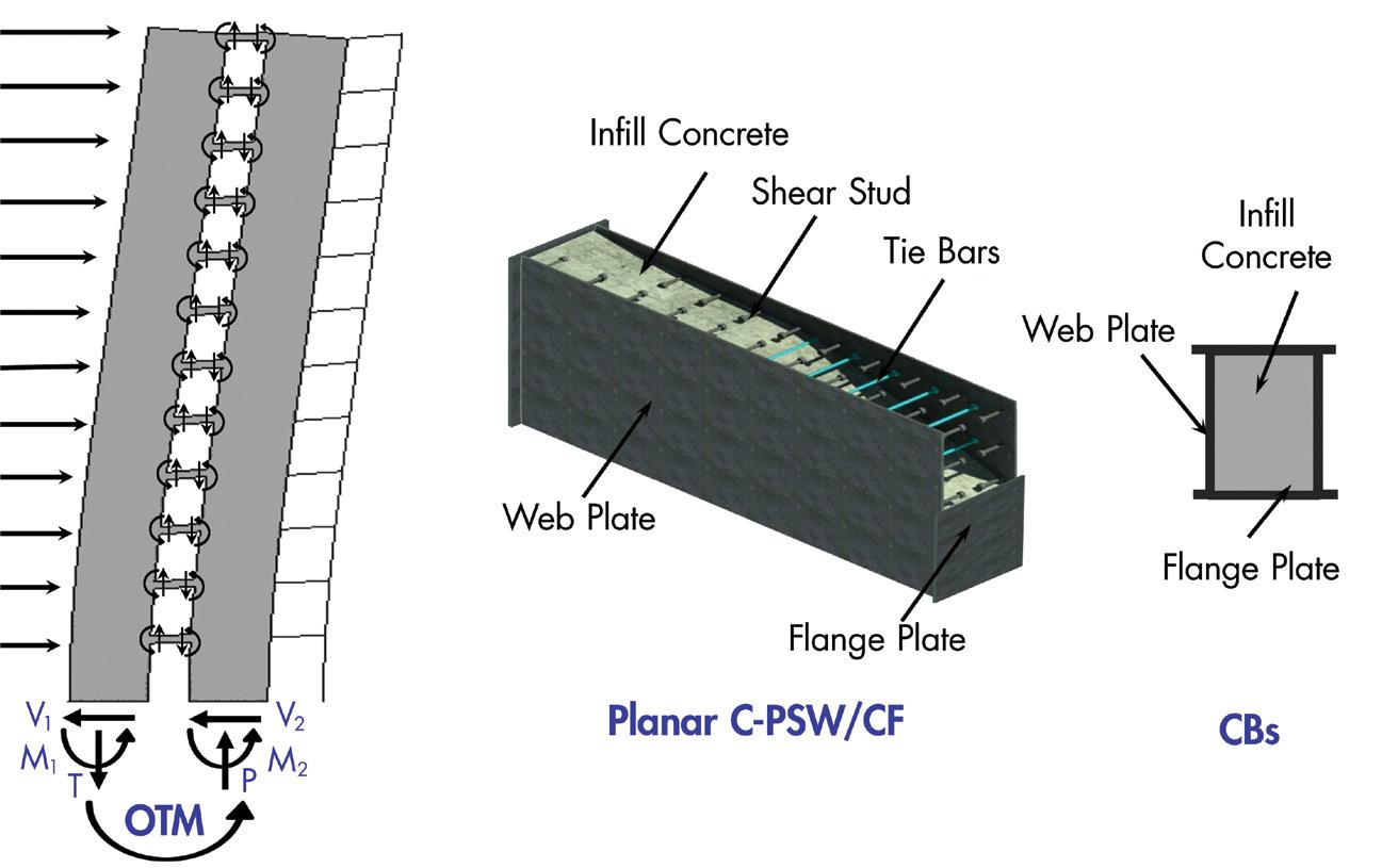
Figure 1. A typical coupled C-PSW/CF system using planar C-PSW/CFs and composite coupling beams.
As evident from its name, the SpeedCore system reduces construction time considerably due to its ability to be installed quickly. Empty steel modules of the coupled C-PSW/CF system – including steel plates, tie bars, and shear studs – are prefabricated in a shop and transported to the site for erection. The erected empty steel modules serve as formwork and falsework during construction and concrete casting. The erected empty modules of coupled C-PSW/CFs can resist a construction load of up to four floors of decking, making it possible to erect the steel modules of the coupled C-PSW/ CF system and steel gravity frames simultaneously. The modules can be filled with either normal or self-consolidating concrete (SCC).
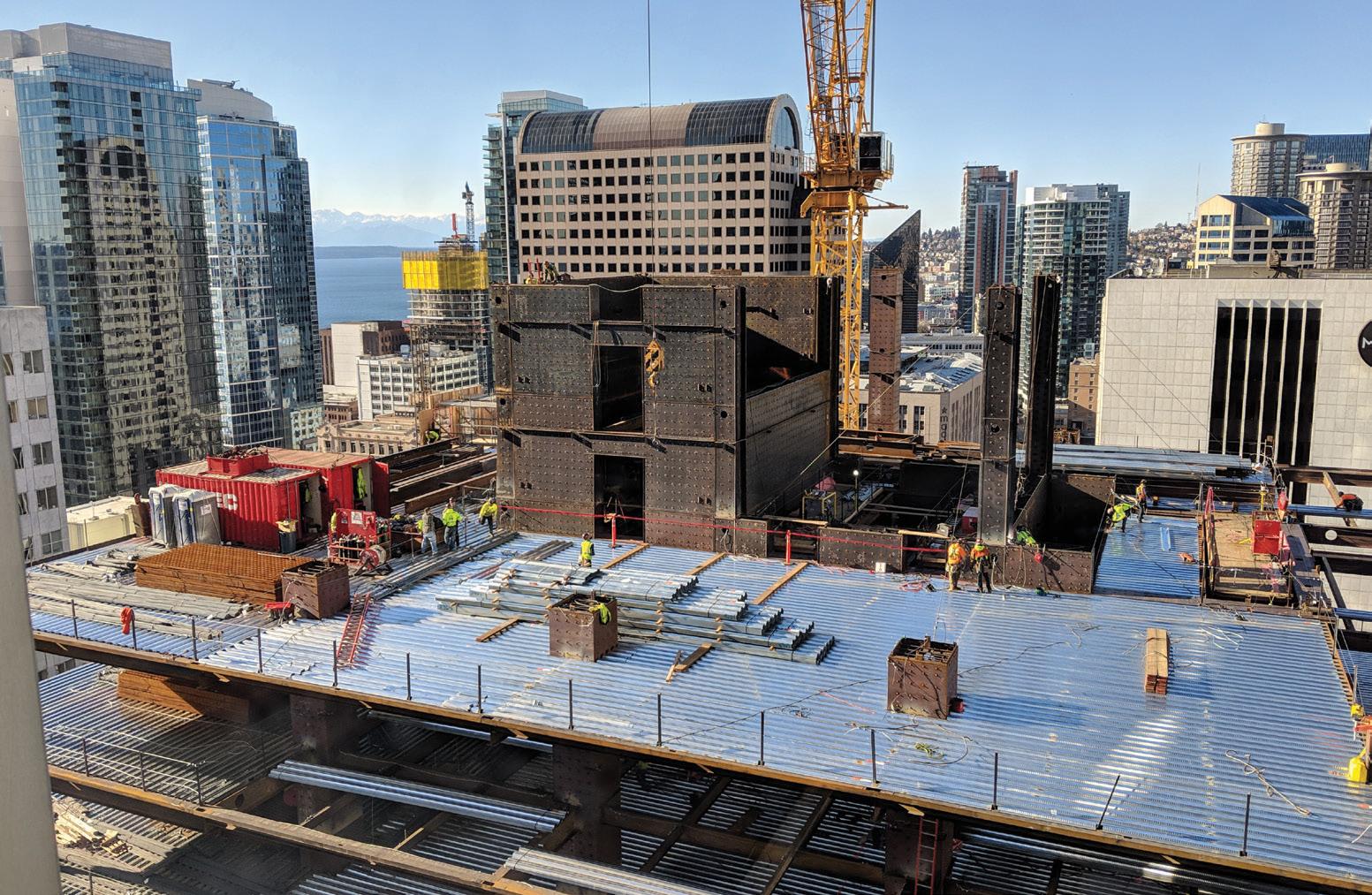
The first high-rise building in the United States to use the SpeedCore system is Rainier Square Tower, constructed in Seattle and designed by Magnusson Klemencic Associates (MKA). This 58-story highrise building was designed and detailed in a seismic region, although it was a wind-controlled structure. The construction of Rainier Square Tower was completed in 2020, demonstrating the feasibility of applying this novel modular structural system in high-rise buildings. Figure 2 illustrates the erection of Rainier Square Tower’s empty steel modules and gravity frames. The use of the SpeedCore system in Rainier Square Tower resulted in a savings of eight months compared to traditional reinforced concrete core walls.
STRUCTURE magazine 12
Figure 2. Construction of Rainier Square Tower in Seattle.
A second project utilizing the SpeedCore system is the 200 Park Avenue high-rise in San Jose, California, under construction at the time of this writing. Figure 3 illustrates a prefabricated empty steel module of coupled C-PSW/CF during the 200 Park Avenue tower construction. Implementing the coupled C-PSW/CF system in this 19-story office tower shaved three months off the construction schedule. Employment of the SpeedCore systems in the mentioned projects resulted in faster construction with remarkably reduced costs compared to traditional reinforced concrete core walls.
Seismic Design Philosophy
Coupled C-PSW/CF systems in mid- to high-rise buildings are designed to resist lateral seismic forces. In the coupled C-PSW/CF system, two or more individual C-PSW/CFs are connected by ductile steel or composite coupling beams. To make a coupled C-PSW/CF system, the individual C-PSW/CFs can be planar, C-, U-, I-, or T-shaped composite walls. As a result, the coupled C-PSW/CF system has a totally different lateral seismic response than uncoupled individual C-PSW/CFs.

In the seismic design of a coupled SpeedCore system, coupling beams and C-PSW/CFs are sized using a capacity design principle. The coupled C-PSW/ CF system is expected to undergo significant plastic deformation at the ends of coupling beams along the structure’s height, followed by the yielding of C-PSW/CFs at the base during a large earthquake event. It is recommended in AISC 341-22, Seismic Provisions for Structural Steel Buildings (Section H8), that composite coupling beams be sized to be flexure-critical members. Implementing strong C-PSW/CFs and weak coupling beams is the seismic design philosophy of the coupled C-PSW/CF system.
Figure 4 shows the seismic design philosophy of the coupled C-PSW/ CF system and a lateral load response
(nonlinear static pushover analysis) of a 12-story coupled C-PSW/CF structure using finite element modeling. The composite coupling beams are designed for code-level seismic forces and have flexural yielding at both ends (Point A). The individual C-PSW/CFs are sized to have flexural yielding at the base after formations of plastic hinges in all coupling beams along the height of the structure (Point B). In other words, the C-PSW/CFs are sized for an amplified base shear, as shown in Figure 4a, which is calculated according to the capacity limit forces from the composite coupling beams and the coupling action. While the flexural plastic hinges are forming at the base of C-PSW/CFs due to the increase in lateral displacement, the lateral load capacity of the coupled C-PSW/CF system increases until fracture initiations in the composite coupling beams take place (Point C). This milestone is considered the ultimate lateral capacity for the coupled system. The ratio of the ultimate capacity to flexural yielding of coupling beams (Point C to Point A) is defined as the overstrength factor.
Finally, the lateral load capacity of the coupled C-PSW/CF system starts to decrease due to fracture initiations in C-PSW/CFs at the base (Point D). As shown in Figure 4b, the finite element model of a 12-story coupled C-PSW/CF structure verifies that the lateral load behavior follows the aforementioned seismic design philosophy.


Dynamic Response
The lateral seismic response of the 12-story coupled C-PSW/CF structure discussed above was evaluated using nonlinear dynamic time-history analysis. Seven different far-field ground motions were chosen for the nonlinear dynamic time-history analyses. The ground motions were scaled to the design basis earthquake (DBE), maximum
JANUARY 2023 13
Figure 3. Prefabricated empty steel module of coupled C-PSW/CF for 200 Park Avenue high-rise.
Figure 4. General lateral load behavior of coupled C-PSW/CF: a) Seismic design philosophy of the coupled C-PSW/CF system; b) Lateral load response of a 12-story structure using finite element modeling.
considered earthquake (MCE), and failure level earthquake (FLE) to evaluate the seismic responses. Figure 5 illustrates the nonlinear time-history response of the structure subjected to Superstition Hills ground motion (El Centro Imp. Co. 1987) scaled to a spectral acceleration of 1.83g (FLE).
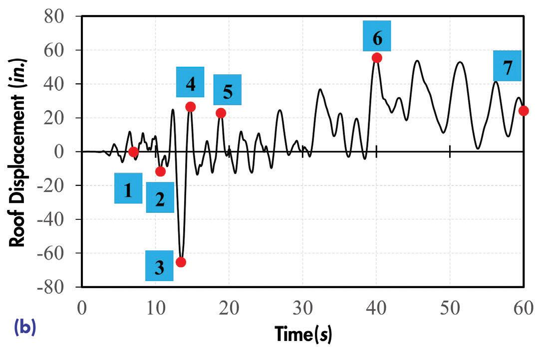

For the DBE and MCE levels, the maximum inter-story drifts of the 12-story coupled C-PSW/CF structure were 0.95% and 1.43%, respectively. The coupled C-PSW/CF structure experienced flexural yielding in coupling beam ends (without any fractures), followed by some yielding at the base of each C-PSW/CFs at the DBE. Similarly,
the coupled C-PSW/CF structure underwent flexural yielding in coupling beams (without any fractures), followed by yielding at the base of C-PSW/CFs at the MCE. The propagation of yielding was noticeably greater at the MCE level than at the DBE level. The ground motion was scaled to a spectral acceleration of 1.83g (FLE) to investigate the failure mode of the structure. The coupled C-PSW/CF structure underwent the following milestones: 1) flexural yielding of coupling beams, 2) flexural yielding of C-PSW/CFs, 3) propagation of yielding, 4) fracture initiation of coupling beams, 5) fracture initiation of C-PSW/CFs, 6) total fracture of coupling beams. Figure 6 illustrates the occurrence of major events, which is in accordance with the aforementioned design philosophy.
Seismic Design Factors
All prescriptive seismic design codes for different structural systems use three seismic factors: (i) a response modification factor, R, ( ii ) an overstrength factor, Ωo, and (iii) a displacement amplification factor, Cd. These three seismic factors are defined for each structural system based on the system-level inelastic response, ductility, failure mechanism, and other seismic factors. The response modification factor, R, is specified for each structural system based on the inelastic response and system-level ductility. The R factor is used to reduce the base shear for the linear elastic design. The overstrength factor, Ωo, is specified as the ratio of the ultimate capacity of the structural system to the first significant yielding. The overstrength factor is used to estimate the ultimate capacity of a structure, considering the failure mechanism, structural redundancy, and material overstrength. The

STRUCTURE magazine 14
Figure 5. a) Earthquake record of Superstition Hills (El Centro Imp. Co. 1987); b) Nonlinear time-history response of 12-story coupled C-PSW/CF subjected to Superstition Hills earthquake (scaled to a spectral acceleration of 1.83g).
Figure 6. Time-history response of coupled C-PSW/CF systems subjected to 1987 Superstition Hills earthquake (scaled to a spectral acceleration of 1.83g).
a)
b)
b)
displacement amplification factor, Cd, is the ratio of ultimate inelastic displacement during the MCE to the elastic response of a structure subjected to the code-level seismic forces. The Cd factor is used to estimate the maximum inelastic lateral displacement and drift from the elastic response of the structure.
A study using FEMA P-695, Quantification of Building Seismic Performance Factors, was conducted to evaluate and verify the seismic design factors (R, Ωo, and Cd) for the coupled C-PSW/CF system. The study was collaboratively accomplished by research teams from the University at Buffalo and Purdue University. The results of the FEMA P-695 study show that seismic factors for the coupled C-PSW/CF system are as follows: a response modification factor of 8 (R = 8), an overstrength factor of 2.5 (Ωo = 2.5), and a displacement amplification factor of 5.5, (Cd = 5.5). It should be noted that the response modification factor of 8 is the highest factor that can be assigned for a structural system according to ASCE/SEI 7, Minimum Design Loads and Associated Criteria for Buildings and Other Structures.

Composite Coupling Beam-to-C-PSW/CF Connection


In the seismic design of coupled C-PSW/CF systems, composite coupling beam-to-wall connections are designed and detailed to develop a minimum chord rotation capacity of 0.03 radians before the flexural capacity of the connection decreases to 80% of the plastic moment capacity of the coupling beam. Researchers at Purdue University developed several possible coupling beam-to-C-PSW/CF connections with the help of an industry advisory panel and fabricator inputs. The seismic responses of these connections were experimentally and numerically evaluated. A possible composite coupling beam-toC-PSW/CF connection is shown in Figure 7. There are slots in the C-PSW/CF web plates, and coupling beam flange plates are inserted into the slots. Coupling beam flange plates are 1 inch wider than the wall cross-section from each side to provide adequate clearance for complete joint penetration (CJP) welding. The slots of C-PSW/CF web plates are beveled and welded to the coupling beam flange plates using CJP welding. The coupling beam web plates are overlapped at the C-PSW/CF web plates, and C-shaped fillet welding is done. The depth of coupling beam web plates is reduced 1 inch from top and bottom at the connection region to provide adequate clearance for fillet welding.
2020 NEHRP Design Example
A seismic design example for an 18-story office building using a coupled C-PSW/CF system is presented in Chapter 5 of the 2020 NEHRP Recommended Seismic Provisions: Design Examples, Training Materials, and Design Flow Charts (FEMA P-2192-V1). The design example shows the step-by-step seismic design procedure of coupled C-PSW/ CF using L-shaped C-PSW/CFs and composite coupling beams. The seismic design procedure for coupled C-PSW/CF systems is in accordance with Specification for Structural Steel Buildings, AISC 360-22, ASCE/SEI 7-22, Specification for Structural Steel Buildings, AISC 341-22, and the upcoming AISC Design Guide 38 for the SpeedCore system. The AISC Design Guide 38 will be published in the upcoming months; however, design examples (Mathcad sheets) from the Guide can be downloaded at https://purr.purdue.edu/publications/3753. Additionally, in the 2020 NEHRP design example for coupled C-PSW/CF, a composite coupling beam-to-C-PSW/CF connection design using a possible connection is presented. The connection design is based on the expected composite coupling beam strength, similar to steel connections presented in AISC 358, Prequalified Connections for Special and Intermediate Steel Moment Frames for Seismic Applications.
Summary
Coupled Composite Plate Shear Walls / Concrete-Filled are used as a distinct seismic force-resisting system in the design of mid- to high-rise buildings. This novel system results in a remarkably shortened construction schedule. Thus, it is known as the SpeedCore system. The seismic design of this revolutionary system can be conducted using ASCE/ SEI 7-22, AISC 360-22, AISC 341-22, and AISC Design Guide 38 (specific to the SpeedCore system). The implementation of this new system in two projects (Rainier Square Tower and 200 Park Avenue) demonstrated the feasibility of applying this modular structural system in the seismic design of high-rise buildings.■
Soheil Shafaei is a Postdoctoral Research Associate at Bowen Laboratory, Purdue University, West Lafayette, IN (sshafaei@purdue.edu).
Amit H. Varma is a Karl H. Kettelhut Professor at Bowen Laboratory, Purdue University, West Lafayette, IN (ahvarma@purdue.edu).
Ron Klemencic is Chairman and CEO at Magnusson Klemencic Associates, Seattle, WA (rklemencic@mka.com).
JANUARY 2023 15
Figure 7. a) Schematic view of coupling beam-to-wall connection details;
Scaled connection specimen tested at Bowen Laboratory, Purdue University.
OUTSIDE the box Design Parameters for Data Center Facilities
 By Eka Linwood, P.E.
The Age of IoT (Internet of Things) has come much sooner than anticipated. The pandemic accelerated the digital transformation process, requiring everyone to be comfortable with technology: fast internet, video conferences, cloud storage, and VPN tunnels. Data center facilities housing servers, switches, data storage, and computer processing functions are also becoming more common as major businesses become more reliant on the cloud (Figure 1). Two common types are colocation and hyperscale. Colocation facilities can serve multiple tenants, while hyperscale facilities typically serve a single tenant. Hyperscale facilities are commonly developed by tenants or with significant involvement from the eventual tenant. The design for colocation facilities is based on a developer’s best guess of what the market and potential tenants would want in a particular location. The data center engineering business is complicated because most data center developers value confidentiality. Non-disclosure agreements are signed between all parties during the pre-qual stage. The nature of risk is different from what is common in structural engineering. Most structural engineers are concerned about life safety and extensive property damage. Data center facilities are typically considered “mission-critical,” where consequential damages are more significant than actual damages. Consider a data center facility for a financial institution, processing billions of dollars worth of transactions daily. Downtime has a devastating effect from a business perspective, so structural design requirements are higher than that required by building codes.
Two organizations in the U.S. publish data center standards: the Telecommunications Industry Association (TIA) and the Uptime Institute. These organizations define the tier standards referenced frequently by data center facilities to indicate a data center’s level of reliability. There are 4 tiers of certification (I-Basic, II-Redundant Capacity, III-Concurrently Maintainable, and IV-Fault Tolerant). Uptime’s facility certification is divided into three phases: design, facility, and operations. Clients often express the desire to get a Tier IV
certification, but then back down after gaining a better understanding of the stringent redundancy requirements (especially around distribution paths) and the associated costs. Most of the requirements imposed by Uptime revolve around mechanical and electrical installations. Due to catastrophic damages associated with structural failures, structural engineering is arguably more important than a data center’s mechanical or electrical design. Damages affecting concrete cover zones, such as spalling or cracking, may not necessarily affect the strength of the structure but have significant potential to cause downtime. For example, spalling concrete may migrate into sensitive IT equipment, or concrete particulates may go into the cooling system resulting in overheating failures.

Identifying a structural engineering guide for the data center industry is difficult because minimum loads are commonly specified by design standards rather than an industry-standard recommendation. ASCE 7-22, Minimum Design Loads and Associated Criteria for Buildings and Other Structures, specifies a 100 psf distributed load or 2,000-pound point load for “Computer use – Access floor systems.” United Facilities Criteria (UFC) 3-301-01 (2018) specifies 150 psf for “Telephone exchange rooms and central computer IT server spaces,” in line with ASCE 7-22’s commentary under Table C4.3-1 for “Computer equipment.” Compare this with the 350 psf recommended by Intel (Facilities Design for High-density Data Centers, 2012). It is clear that there is a discrepancy between what the ASCE standard requires as a minimum and what the actual industry expectation is.
2.
ASCE 7-22 states that the “weight of actual equipment or stored material when greater” should be used. The issue is that most structural engineers are not IT professionals. Plan views and white-space layout do not communicate rack specifications. In fact, rack specifications are not typically specified until a tenant is on-board, sometimes
STRUCTURE magazine 16
Figure 1. Various utilities go in and out of data center facilities into a crawl space of a seismically isolated building.
Figure
Typical data center HAC layout.
much later in the construction process. As a result, owner’s representatives may lack awareness during the design phase that the 3,000-pound rack about to be installed may exceed the building structure’s capacity. ASCE commentary also states that “fixed service equipment” can be treated as dead load rather than live load. However, data center racks are arguably live loads because the heaviest portion of the rack is the server itself, which can be “hot-swapped” for maintenance.
Table 1. Typical weights for electrical conduits.
Conduit Size Est. Weight (lb/ft)
3-inch 17 4-inch 26 5-inch 37 6-inch 53
Estimated weight includes wire (THHN/THWN/ XHHW based on NEC compliant fill ratio) and conduit weight (galvanized steel).
Data center facilities usually consist of HotAisle Containment (HAC) modules. An individual data center rack typically measures 2 feet wide x 4 feet deep, rated for 3,000 pounds. The weight of the rack itself is typically about 300 pounds, resulting in approximately 412.5 psf of live load due to each rack on its respective footprint.
Dimensions of the rack access space and width of an HAC are unique to each data hall design – highly dependent on tenant and location. For example, assume a floor module occupying an area of 16 x 20 feet. Figure 2 illustrates how the racks are organized in the white-space. Depending on the layout, the HAC structure is estimated to weigh up to 2,000 pounds. The raised access floor (RAF) weighs about 12 psf, equivalent to 3,840 pounds over a 16- x 20-foot area.
Power distribution unit (PDU) whips are usually installed under the RAFs, introducing a significant amount of weight. Networking cables (LAN or Fiber Optics) could also be installed under the RAF. The occasional maintenance also introduces construction loads, such as a manlift weighing 1,000 pounds. Additionally, a 6-person team occupying this space adds a load of approximately 1,500 pounds. The total of these loads is: 66,000 pounds (rack) + 2,000 pounds (HAC) + 3,840 pounds (RAF) + 3,000 pounds (assumed for PDU whips/LAN cables) + 2,500 pounds (manlift/construction team) = 77,340 pounds spread out in a 16-x20-foot area. This is equivalent to approximately 240 psf, about 60% higher than the minimum specified by ASCE.
Several other factors have not been considered in this design live load, such as the load distribution of a single HAC may be concentrated around a single structure bay, or several utilities are in the space (chilled water, network backbone cabling, main power to PDU cabling). These hanging collateral loads add a significant load on the structure.
Often, several electrical conduits are run in the same general vicinity since power needs to be routed from the same electrical room or generator room. Table 1 shows the typical weight associated with various sizes of electrical conduits.
Fiber optic (FO) cables are typically routed from the “Meet-Me Room,” where the network connections from the outside plant (OSP) come into the building and “meet” with the production FO cables for the white-space. Plenum FO cables are likely used in data center applications, but LSZH/ riser cables are heavier, complicating the design process. The number of fibers in an FO cable also affects the size/weight of the cable, but lower-count fibers are typically heavier than higher-count fibers (2-fiber cables are “denser” than 144-fiber cables). Table 2 provides a reference for
network cable design weights based on the width/height of the cable-tray and cable type (Cat 5e vs. FO).
Several tables are provided in this article to assist with designing these utility supports based on typical standard practice for a data center. For example, Table 3 (page 18) provides a reference for weights of chilled water lines typically routed through cast-iron plumbing. However, due to the significance of these loads, the structural engineer of record is encouraged to talk with the project’s mechanical and electrical engineer of record to understand how infrastructure utilities are routed throughout the building so the weights of these can be accurately accounted for in the building structure’s design.
Through value engineering, contractors often identify conservative assumptions commonly used in structural design and provide feedback on constructability. Although cost-efficiency is essential to any project, speed-to-market is key in data center projects. IT equipment evolves continuously and quickly. For example, some clients request the racks to be double-stacked, resulting in very highdensity white-space. As a result, clients typically prefer a conservative structural design to ensure the capacity to upgrade, when required, is included. In addition, data center facilities undergo significant alterations throughout the project’s life cycle, and the building’s structural design should account for this.
Structural retrofits in a live data center are expensive. Therefore building these potential upgrades into the initial design is much more cost-effective. Since the equipment in data center facilities cannot be exposed to water – very early warning aspirating smoke detection (VESDA) fire-detection systems are installed. When fire alarms are turned off (as required for construction), fire-watch personnel are required. Other considerations for structural retrofits include dust and vibrations that sensitive IT equipment cannot tolerate. Negative air containment is required to contain dust produced by construction projects. Dust can get into the fans and various cooling systems that are crucial for the continuous operation of the IT equipment. In addition, chipping and grinding can produce vibrations outside the vibration limits specified by the IT equipment’s manufacturer. Vibration limits are typically specified as either shocks or random vibration, and operational vs. non-operational. Logically, shock limits should be higher than random vibration since random vibration implies a long duration of an equipment’s continuous vibration exposure. Non-operational is typically applicable when the equipment is in transit.
Requiring that the data center’s operators contract with a structural engineer for every minor modification is not a reasonable expectation. Mechanical or electrical engineers almost exclusively perform maintenance. Structural engineers’ involvement on the operations
JANUARY 2023 17
Table 2. Typical weights for network cables. Total Estimated Weight
Cable Type: Fiber Optics (Plenum) Fiber Optics (LSZH / Riser) Cat 5e Height (in) (in) Width 2 4 6 2 4 6 2 4 6 12 9 14 20 10 17 24 11 19 27 18 12 20 29 14 24 35 16 27 40 24 16 26 38 18 32 46 21 36 53
(lb/ft)
side is almost non-existent, so oversight of structural items is likely. This introduces operational risks that are undesirable to any data center tenant.
Construction in a live data center introduces various risks, such as vibration, access, dust, and potential property damage from the various construction activities. Due to these risks, clients sometimes occupy/load the top floor of a building first, then use a top-down approach for occupying lower floors. The occupancy of a data center depends significantly on tenants and market conditions; thus, a data center or parts of it may remain vacant for a few years. As structural engineers, we are taught seismic concepts in terms of an inverted pendulum. By loading the data center top-down, the building is the literal definition of an inverted pendulum and will move based on its fundamental mode.
Table 3. Typical weight for cast iron plumbing. Nominal Pipe Size Est. Total Weight (lb/ft) 4 inches 17 6 inches 33 8 inches 52 10 inches 77 12 inches 101 14 inches 124 16 inches 161 18 inches 204
systems such as power/water systems may occur. Damages to these systems can result in operational downtime. A data center developer trying to design based on Tier III/IV standards would have also completed other risk assessments such as flood risk, air quality, blast risk, tornado, power reliability, etc. In the context of performance-based design: if a data center is to be designed to Uptime’s Tier III or IV standard, then Risk Category IV (Immediate Occupancy / Operational) should really govern the structural design.
Seismic risk exposure to data centers does not stop at the building. In fact, as indicated previously – data center equipment is sensitive to vibration. Vibration limits of IT equipment can vary broadly. For example, a director switch (IT equipment) has an operating random vibration limit as low as 0.0005 grms (between 10Hz to 200Hz), implying that a person walking on the RAF panel next to the rack can affect the IT equipment adversely. Looking at the shock criteria of the same equipment indicates that the equipment can withstand a 10g magnitude of shock. The intent of the vibration limit is likely to avoid a situation where the IT equipment is placed in a constantly vibrating environment (proximity to fans or in a moving vehicle). Conversations with the OEM uncover that such limits were established based on the tests the equipment has been exposed to (and successfully passed). This differs from a limit typically established in the structural engineering world, where components are tested to failure. It is unclear what exceeding the vibration limit would do to the equipment. CNET published an article where simply “shouting” at the data center equipment can introduce enough vibration to affect latency and impact I/O operations. Due to the complexity of vibration analysis/testing, a common statement from OEMs is that the seismic forces do not impact the equipment, without a clear definition of impact
Rather than trying to chase the OEM’s vibration criteria, a realistic objective is to design for the stability of the IT racks based on ASCE 7-22 Chapter 13 on Non-structural systems – ensure that it does not overturn from the lateral overturning seismic force. The racks should be braced against the building to minimize damage to its contents. Each of these 2- x 4-foot IT racks is typically valued at $200,000. Therefore damage to a single rack can cause significant monetary loss to the owner.

Damages to structural systems in any facility are catastrophic – a building can be unoccupiable or significant damages to non-structural
Uptime Tier III’s expected availability target is 99.982%, and Tier II’s is 99.741%. In structural engineering terms, ASCE defines Design Basis Earthquake (DBE) and Maximum Considered Earthquake (MCE) as 10% and 2% probability of exceedance in 50 years, respectively. Table 4 indicates repair time. However, this timeline excludes the time required to identify, plan and permit the work, arrange financing, and hire and mobilize the contractors. For example, at a 50-year return period, repairs must occur within 36 days (for a DBE) and 180 days (for an MCE) to comply with Uptime’s target availability for Tier III. A similar calculation to comply with Tier II requirements yields a 15-month and 79-month repair time for DBE and MCE, respectively.
Another lateral load that is sometimes considered in a data center’s building design is tornado load. Introducing tornado loads into a building’s design may result in the building roof experiencing uplift. Concrete ballasts/topping slabs are sometimes required, introducing a significant dead load to the roof. In this case, it is often better to design for a heavier roof live load criterion rather than the 20 psf minimum required by ASCE. In addition to the overhead utilities mentioned earlier, heavy equipment such as cooling towers, load banks, and water tanks are sometimes located on the roof to decrease land usage. Therefore, it is logical to incorporate the topping slab into the design and get additional roof live load capacity for the project.
Summary
The gravity and lateral load design criteria for data center facilities differ from typical buildings – even Risk Category IV buildings defined by ASCE. Structural engineers play an essential role in the data center facility’s design to ensure the facility’s uptime. Three design objectives typically apply to data center design projects: speed-to-market, scalability, and resilience. Mission-critical data center facilities serve as technological infrastructure that must remain operational after natural disasters, such as earthquakes, hurricanes, tornadoes, etc., to aid disaster recovery and return to normalcy.■
STRUCTURE magazine 18
Table 4. Excerpt from FEMA P-58-5 Table 6-1 on repair time expectation. Facility Type Repair Time Expectation (days) DBE MCE Risk Category II – Office 45 150 Risk Category II – Medical Office Building / Lab 60 180 Risk Category IV – Emergency Operations Center 30 75 Risk Category IV – Hospital 45 100
Eka Linwood is a Project Manager with Black & Veatch, an engineering and construction (E&C) firm (linwoode@bv.com).
High-capacity loads. All-wood aesthetic.

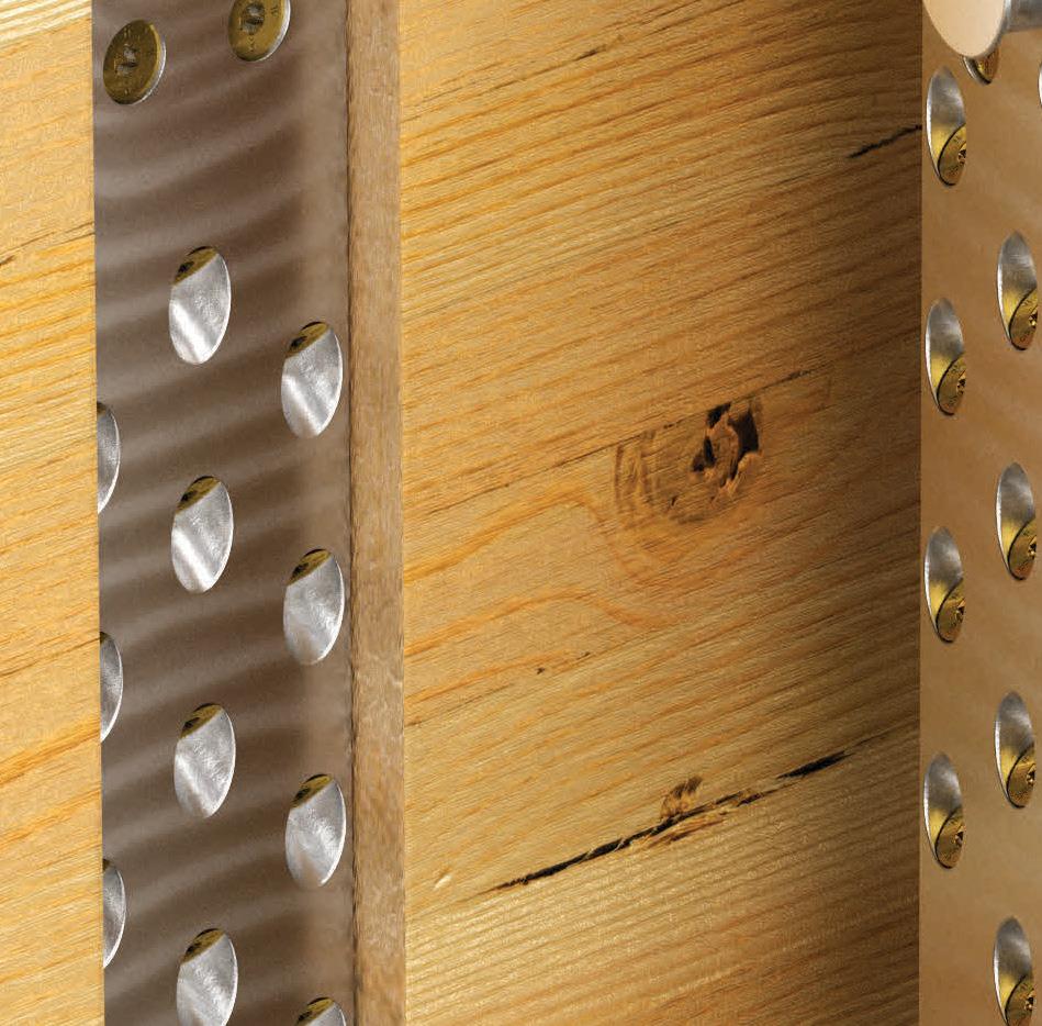
Introducing the Simpson Strong-Tie® ACBH aluminum concealed beam hanger.
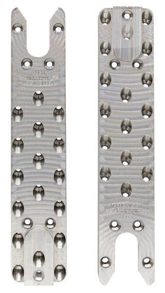

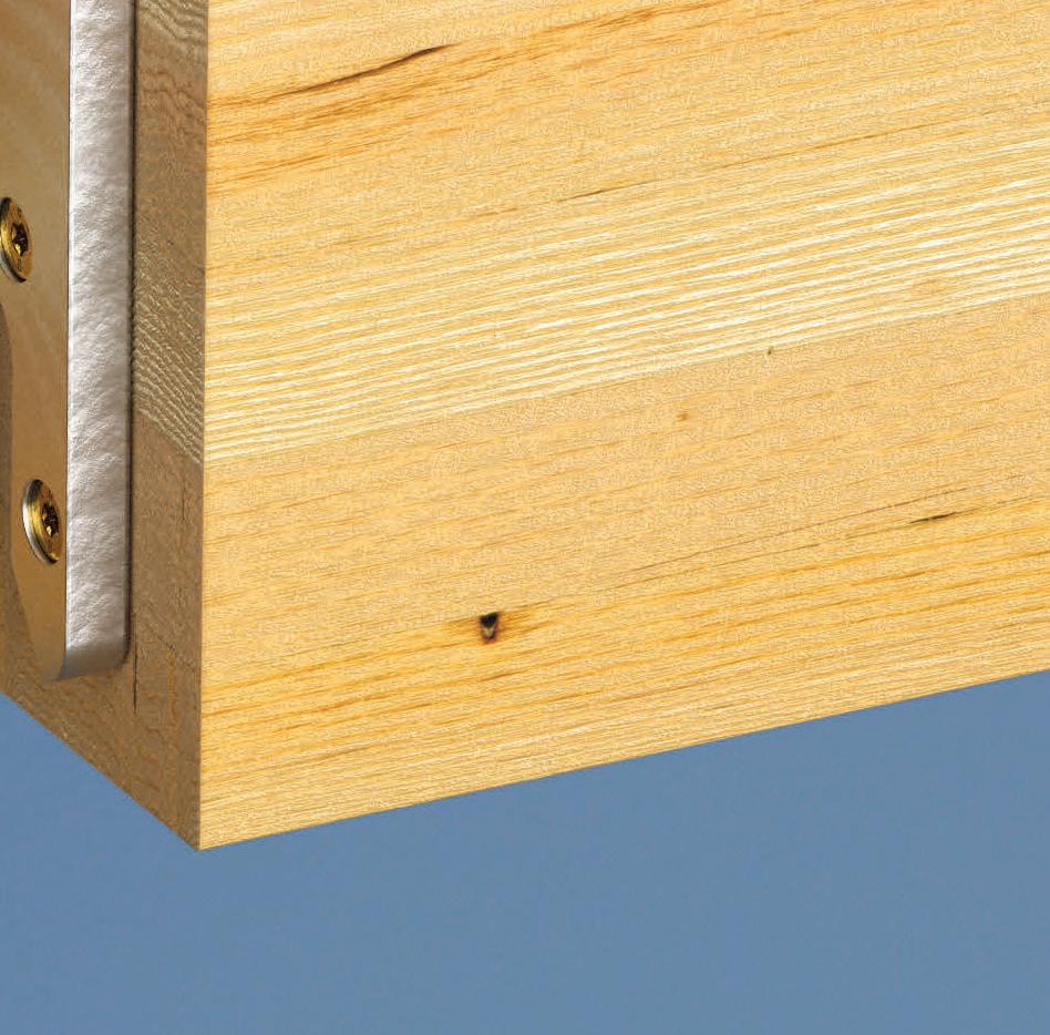
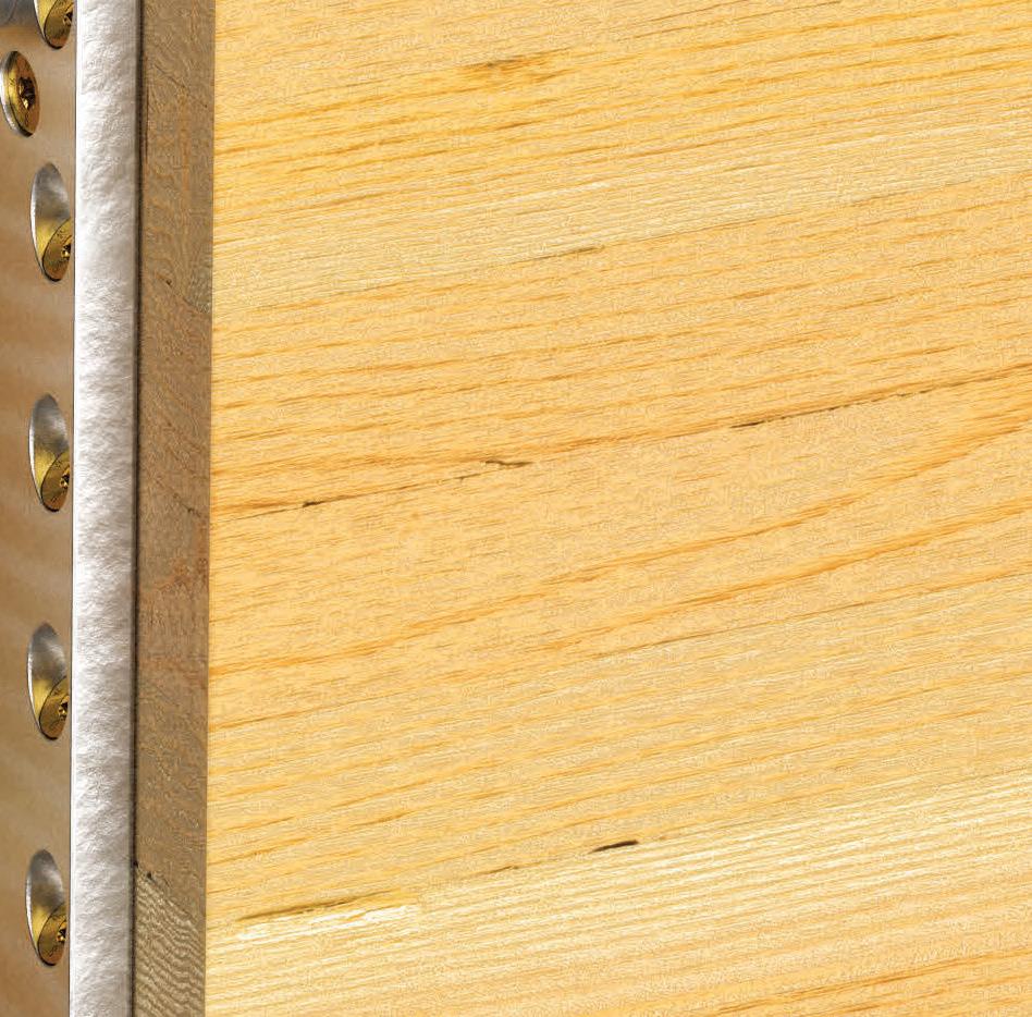
Hidden from view while displaying the beauty of wood beams, the ACBH is tested for drift and supports higher loads than any other comparably-sized concealed beam hanger. It’s also tested to achieve one- and two-hour fire resistance ratings.


The ACBH installs easily in the factory using Strong-Drive ® SDCF Timber-CF structural screws, and offers generous fit-up tolerance that saves time and effort when the beam is lowered into place. The ACBH is made in the US, widely available, and backed by our expert service and support.
To learn more, visit go.strongtie.com/masstimber or call (800) 999-5099.





©2023 Simpson Strong-Tie Company Inc. ACBH22
Mass Timber Solutions | Products and Service for Smarter Building
One Step Closer to Net-Zero
High-Strength Reinforcing and Performance-Based Design
By Scott Erickson, P.E., S.E., and Erin Spaulding
Located in the 14-square-block downtown redevelopment area and two blocks from City Hall, Fifteen Fifty and 49 South Van Ness stand literally at the center of San Francisco. A portion of the two-building project, the 16-story steel-framed office tower (49 South Van Ness), is home to the City’s Department of Building Inspection, which set a high-performance standard for its new home: a Category III building to increase seismic resiliency. Add in the 39-story concrete residential tower (Fifteen Fifty) – which ties into an at-grade alley structure with the office tower – along with a high-water table and the region’s high seismicity. is results in a considerably large and complicated puzzle to solve.
With 780,000 gross square feet in the residential tower and 460,000 for the office tower, Fifteen Fifty and 49 South Van Ness amass over 1.2M square feet of constructible area. To keep costs low relative to the project’s size and quantity of materials, DCI Engineers – the SEOR for both buildings – opted to pursue a Performance-Based Design using 80 ksi high-strength vertical reinforcement in the concrete shear
walls – the first high seismic project to do so in the United States. As a result, the amount of reinforcement was reduced, and a more robust design was provided.

The Project Pieces
e residential building is an all-concrete tower with a central concrete core wall lateral system and two separate blade walls in the two wings of the building. Post-tensioned slabs are used above grade with mild reinforced slabs at and below grade. e office tower is a steel-framed structure above grade and mild reinforced concrete below grade with a concrete shear wall lateral system in the tower and another blade wall in the wing. Both buildings are tied together at grade and for the two levels below grade. is connection required extensive analysis of force transfer between the buildings at this level. Also, a continuous mat foundation ties both buildings together and resists a full story of hydrostatic pressure. e continuous mat and connection of the two

STRUCTURE magazine 20
Rebar in the residential core.
buildings eliminated any bathtub waterproofing concerns and made for a more economical project by eliminating interior basement walls to separate the two buildings.
Pushing Innovation Forward
A performance-based seismic design approach was initially pursued simply because the residential tower height is over 240 feet tall, which is typical for high-rise residential towers in seismic regions. This alone saves on material.


But that approach provided an additional design assist when the City of San Francisco Department of Building Inspection requested that its new headquarters building remain serviceable under an extreme seismic event. The desire was to allow the facility to be used during emergencies to help bring critical functions of the City government back online faster. Since the team was already using a performancebased design approach, it was determined to design to Risk Category III (typically a 25% increase in forces) to increase the resilience while maintaining the same cost as a Risk Category II building.
Code designs do not require an explicit check of all the concrete strains, reinforcing strains, and building deformations for a maximum-considered seismic event. In contrast, a performance-based design approach requires that these are checked and met. It also grants the freedom to explore deviating from strict code rules. In this case, DCI pursued the use of higher Grade 80 vertical reinforcing in the concrete shear walls when the code limit at the time was 60 ksi. This provided for an efficient residential tower and a more resilient Risk Category III office building for the cost of a Risk Category II building.
Grade 80 Approval
It is important to note that a performancebased design approach does not guarantee immediate approval of any concept. As the name suggests, a proposed concept must perform adequately to be approved. The simplest way of proving performance is through physical tests. An example is to use past tests to model non-linearity in the analyses. The performance-based design process also requires a panel of national experts to review and approve the design. Typically, a practicing engineer, a professor who does research in the field, and a seismologist are all required to review the project. The analysis, calculations, and any deviation from the code must be rigorously reviewed and approved by the peer reviewers and the building department.
Grade 80 reinforcing was already being produced during the project’s early design.
Still, it was mainly used for projects in nonseismic areas or large foundations where the inelasticity of the material was not a concern. Therefore, additional research by the design team was required to evaluate the viability of this solution. First, information from several manufacturers of Grade 80 reinforcing throughout the west coast was collected. Next, actual yield and ultimate strengths along with elongations were plotted, from which a lower bound estimate of the minimum yield that any producer could achieve along with the approximate overstrength (ultimate divided by yield) was determined.
Determining reinforcing properties was only part of the picture. Reinforcing in tension is governed by yield and tensile strength. However, reinforcing in compression is governed by how often it is supported along its length – or in structural terminology, how often confinement reinforcement is spaced along its length. The existing American Concrete Institute code at the time, ACI 318-14, Building Code Requirements for Structural Concrete and Commentary, had governing minimum limits of six times the bar diameter or six inches, whichever was smaller. But those were based on Grade 60 reinforcing tests. So, the team needed to figure out a way to justify the confinement reinforcing spacing for the higher Grade 80 reinforcing.
As there was not much research on low cycle fatigue tests of Grade 80 reinforcing, the team decided to require tests for the project to prove it would work. The decision was made to reduce the confinement spacing from six times the bar diameter to five times the bar diameter to achieve the required results.
Low cycle fatigue tests on all vertical Grade 80 reinforcing were required in the project specifications for the actual mill certs submitted for the project and all bar sizes used.
Low Cycle Fatigue Testing
As a result of these requirements, the team needed to wait until just before construction to get results on the tests. This was nerveracking for the team as the entire analysis assumed that the test results would pass. The whole team took a leap of faith.
As a requirement for a passing grade, the tests needed to achieve at least 1.5 times the number of cycles exceeding the mean yield strain for the non-linear analysis. All mean strain results were below the acceptable limits of +1% in tension and 0.5% in compression, for a total strain range of 1.5%. The loading protocol was determined by taking 1.0 times the tensile and compressive acceptance strains. A critical strain gage for each Perform 3D tower model was selected based on the
JANUARY 2023 21
Stepped-back waterfall balconies created unique framing challenges at the Mission and Van Ness corner.
Concrete shear walls are shown in blue, and the street wind mitigation canopy is shown in purple.
Grade 80 reinforcing data is used to determine lower bound modeling parameters.
maximum mean strains (modeled gage length was approximately 6 feet). The time history results for the critical gage were plotted, and the number of strain cycles above yield was recorded for each ground motion.

Worst case cycles past yield occurred in the residential tower model, with a total of 11. Taking the product of 1.5 and 11 yields a minimum of 17 cycles to failure for the testing criteria. For the project specifications, 30 full cycles were conservatively used as the requirement. Previous prediction models estimated the team could achieve 40 cycles to failure, so using 30 as the criteria seemed reasonable.
Bar sizes of #8, #9, #10, and #11 were used and tested. Actual results for ASTM A706, Grade 80 reinforcing used in the project produced test results of 175 to 275 cycles depending on the bar size, which exceeded expectations.
Closer to Sustainable Resilience
In the end, the shear wall vertical reinforcing is a mixture of Grade 60 and Grade 80. Spacing and size rules sometimes governed the minimum reinforcing area for higher stories where demands are lower, and Grade 60 was more appropriate. Grade 80 reduced shear wall congestion on the lower stories and made for easier construction of both buildings.
Higher-strength reinforcement reduced the amount of reinforcing steel required in the shear walls while providing the same level of resilience and ductility. The results included a reduction in vertical reinforcing in many stories by 25%, thus saving the project more than $1M worth of material costs.
The low cycle fatigue testing that was performed on the Grade 80 reinforcing for this project and the new rules developed for confinement tie spacing as a result of the tests have resulted in new confinement rules that are now incorporated into ACI 318-19 for Grade 80 vertical reinforcing in shear walls – a new standard moving forward.
The introduction of higher-strength reinforcing in this project puts the industry one step closer to meeting the goals of the Structural Engineers 2050 Commitment Program. It provides new tools to help reduce the building industry’s carbon footprint.
Structural engineers can make a difference in creating sustainable and resilient buildings on a large community scale, one small innovation at a time.■
Project Team
Owner: Related California, City of San Francisco
Structural Engineer of Record: DCI Engineers
Architect (Fifteen Fifty): SOM and HKS Architects
Architect (49 South Van Ness): SOM
General Contractor (Fifteen Fifty): Build Group Inc.

General Contractor (49 South Van Ness): Pankow
Geotechnical: Langan Engineering and Environmental Services, Inc
Scott Erickson is a Principal with DCI Engineers in Seattle (serickson@dci-engineers.com).
Erin Spaulding, Editor, is the Communications Manager for DCI Engineers in Seattle.
STRUCTURE magazine 22
Biosciences Hub
New Life for the Berkeley Art Museum Building
By Allen Nudel, S.E., Masume Dana, S.E., and Andrew Salber, S.E.


The Berkeley Art Museum (BAM) building was completed in 1970 and is an architecturally significant reinforced concrete building located on the University of California, Berkeley (UCB) campus. Originally designed by Architect Mario Ciampi, it is one

of the most impressive examples of Brutalist architecture in the San Francisco Bay Area and is listed on the National Register of Historic Places. As a result of seismic deficiencies exposed by the 1989 Loma Prieta earthquake and subsequent studies that indicated the cost of a complete seismic retrofit would be similar to a full rebuild, the museum relocated to a new building in 2014, and the BAM building was left unoccupied. In 2016, the California Institute for Quantitative Biosciences (QB3) began a project to reuse the building as a full-service life sciences incubator. As a textbook example of successful adaptive reuse, the transformation of this landmark building incorporated a seismic retrofit into a complicated space, preserved the historic exposed concrete structure, replaced virtually all M/E/P/Fire systems, roofing, and skylights, and improved the building’s accessibility.
Building Description
Asymmetric braced frame elevation.
e existing structure is a complex non-orthogonal threedimensional space. e signature architectural feature of the building is a large atrium, with five upper gallery levels partly cantilevered high above the atrium floor, all covered by a long-span roof with large skylights. In plan view, the upper gallery levels, each separated by a concrete wall, fan away from the center of the atrium in a nautilusspiral shape, with walls running in the radial direction. ere are no concrete walls in the orthogonal “tangential”

JANUARY 2023 23
UC B’ N
Street-level view of Bakar BioEnginuity Hub. Courtesy of Bruce Damonte.
direction. The upper galleries are terraced, and each level occupies a unique elevation separated with a five-foot vertical step. The upper gallery floors consist of two individual slabs (sandwich slabs) separated by a 3-foot interstitial space. Likewise, the concrete shear walls appear to be several feet thick but consist of two relatively thin walls with an interstitial space.
This unique layout allowed for the concealment of vertical and horizontal M/E/P/Fire systems, allowing the Brutalist concrete structure to be universally exposed throughout the building. Each upper gallery level is supported by the radial concrete walls on two sides, but the floor framing is rigidly joined only to one of the walls. The other wall was joined to the slab with thermal expansion joints. The expansion joints contributed to well-performing concrete with virtually no notable cracking after fifty years of service. However, these structural features – lack of a clear diaphragm, disjointed structure, and lateral system in only one direction – are the hallmarks of poor seismic performance. A 2001 temporary retrofit project added braces in the tangential direction, but only on one side of each upper gallery level. Therefore, each upper gallery level had lateral support only on two out of the four sides. The building sits on a foundation of reinforced concrete pier caps and drilled piers, with piers ranging from 18 to 54 inches in diameter and 15 to 85 feet of embedment. The 2001 temporary retrofit bracing is also supported on pier caps and drilled piers for consistency with the original foundation system.
Performance Objectives
UCB’s Seismic Safety Policy requires that buildings meet the Life Safety and Collapse Prevention performance objectives at BSE-R and BSE-C seismic hazard levels, respectively. The building was modeled in CSI Perform 3D and included the entire lateral system, part of the gravity system, and the existing pier foundation system. The 2001 temporary retrofit steel columns, braces, and concrete piers were also included in the model. A seismic evaluation based on the American Society of Civil Engineers’ ASCE 41 Nonlinear Dynamic Procedure (NDP) indicated that BAM did not meet UCB’s minimum requirements for existing structures. Significant damage was expected in the shear walls due to a lack of ductile detailing. A major seismic event could result in loss of gravity support at several locations, including the gallery expansion joints, indicating that a seismic retrofit was necessary.
Selection and Construction

There were several essential criteria in the selection of a retrofit’s structural scheme. The primary criterion was maintaining the building’s historical importance and character. Following the U.S. Secretary of the Interior’s Standards for Rehabilitation and Guidelines for Rehabilitating Historic Buildings and criteria from the historic preservation architect, the new retrofit elements should be clearly identifiable compared to the structure’s historic fabric. Since the interior and exterior exposed concrete was a character-defining feature of the building, a structural steel retrofit scheme was deemed preferable to concrete. Most retrofit elements are exposed in the finished condition, and it was important to the Architect that the retrofit elements be aesthetically pleasing. Careful attention was given to drawings and specifications to achieve a high-quality aesthetic for braces, gusset plates, bolts, welding finishes, and paint color. Several structural details were customized to add tapered sections and stiffener plates to achieve an aesthetic compatible with the structure added in 2001.
The existing concrete shear walls were very rigid. Rigid steel braced frames were selected to achieve drift compatibility between the existing and new structures. A Buckling-Restrained Braced Frame (BRBF) system was used to allow for fine-tuning the stiffness of the bracedframe system; the core area of each BRB could be increased as required to match the stiffness of the corresponding concrete wall. The BRBF system was added to each upper gallery level in both the radial and tangential directions, forming a complete four-sided lateral system for each level. Introducing the retrofit braced frames into the analysis model significantly reduced the expected drift of the building, reducing strain in non-ductile concrete elements, limiting damage to the rest of the structure, and meeting UCB’s seismic performance requirements. The final BRB core areas were determined after several iterations of computer analysis, and the analysis confirmed compatibility between the existing and new structural elements.
Layout and constructability of the new retrofit braces, beams, and columns were critical for the project’s success, both for optimizing the architectural layout of a challenging adaptive-reuse project and limiting damage to the existing structural components in the building. Some structural demolition was necessary to erect the new retrofit steel. The full-height steel columns had to punch through six structural slabs (two sandwich slabs and two regular slabs) between the roof and the foundation, and damage at each level had to be carefully considered.
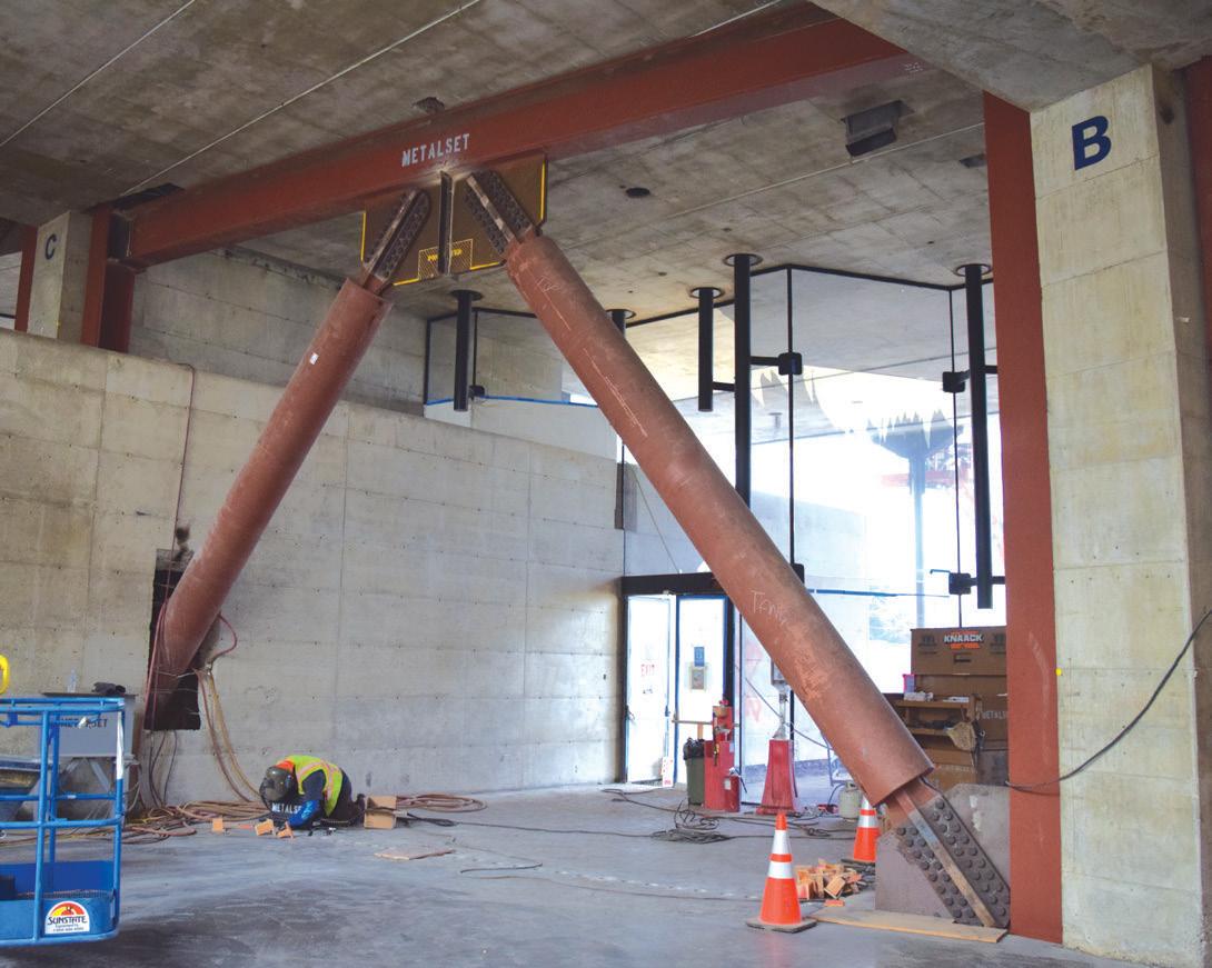
STRUCTURE magazine 24
Scarification of existing foundation concrete.
Installing braced frames adjacent to existing concrete.
Rigorous field verification confirmed that the existing structure was primarily built following the 1970 as-built drawings, and structural members, connections, and demolition extents were detailed to account for tolerances from the original construction and the needs of the steel erector. Early involvement from the Contractor helped generate a positive design feedback loop between the needs of the new structure, the Contractor’s means and methods, and the demolition of the existing structure as required for steel erection. Columns were located within 2 inches of the existing concrete walls, and column splices would have involved blind-side CJP welds, which posed numerous challenges for welding and inspection. To avoid this, an erection sequence was selected in which column base plates and 4-foot-tall column stubs were installed, after which the remainder of the approximately 60-foot-long column was dropped in a single piece through the roof, upper galleries, and other floors. Tight coordination of demolition and new steel allowed for demolition that was barely larger than the cross-section of the steel column. A similar constructability modification involved using non-symmetric braced frames to avoid existing structural gravity elements at the upper gallery levels. e non-linear analysis model was used to evaluate the steel elements for forces resulting from this asymmetry. Field verification was critical to avoid costly and schedule-impacting clashes during steel erection with tight clearances between existing and new structures. e importance of field verification was emphasized through all communications with the Contractor during project meetings, RFIs, and shop drawing reviews. A collaborative team spirit was critical to the success of this project.
At the foundation level, the new steel columns do not align with the existing drilled piers. Early in design, it was determined that new deep foundations would be infeasible due to tight-overhead restrictions in the existing basement levels. To support the new steel columns, a transfer foundation system was designed in which a large, sub-grade concrete transfer beam spanned between existing drilled piers to support the new steel columns.
Conclusion
e seismic retrofit, along with upgrades to accessibility and mechanical systems, has extended the life of this landmark building far into the future by repurposing a disused but highly treasured building. e structure now houses research aimed at making the world a better place. e goal of linking professional, cutting-edge researchers with UC Berkeley students is to encourage collaboration among bright minds and inspire the next generation to achieve the impossible. e parallels between the current use as a research facility and the original use as an inspirational art museum are evident.■
All authors are with Forell | Elsesser Engineers in San Francisco.
Allen Nudel is a Principal and the Director of Business Strategy (a.nudel@forell.com).
Masume Dana is a Senior Associate (m.dana@forell.com).
Andrew Salber is a Senior Engineer (a.salber@forell.com).
Project Team
Owner: QB3 / University of California Berkeley
Structural Engineer: Forell | Elsesser, San Francisco, CA


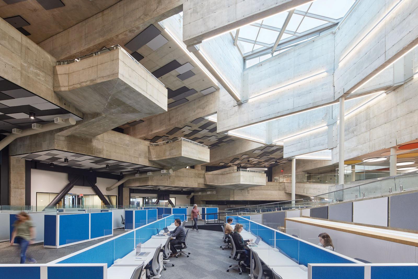
Architect: MBH Architects, Alameda, CA
Contractor: Plant Construction, San Francisco, CA
JANUARY 2023 25
Interior atrium of bakar BioEnginuity Hub. Courtesy of Bruce Damonte.
An Iconic Structure Rises in Little Rock
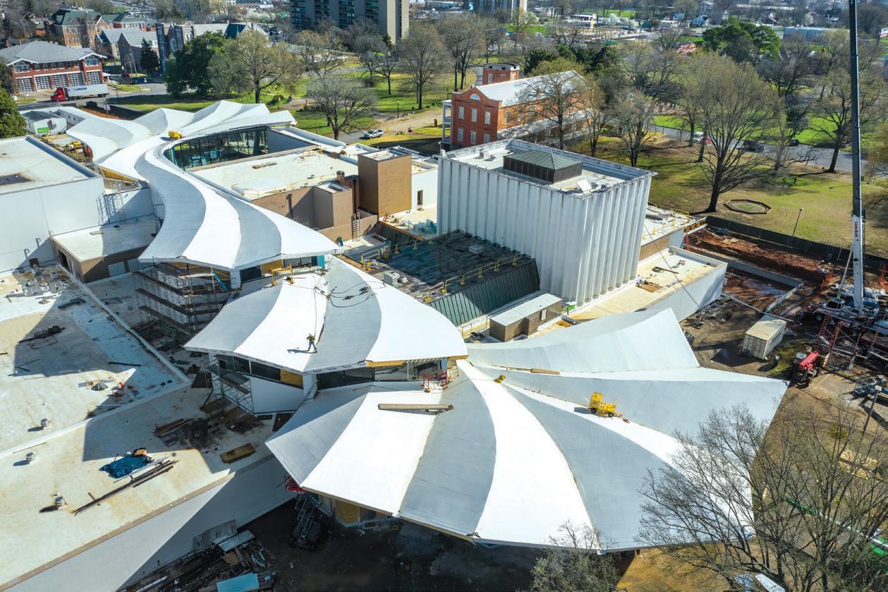 By
By


MacArthur Park in Little Rock, Arkansas, opens in the spring of 2023 with a significant update to one of its most familiar structures. The reimagined Arkansas Museum of Fine Arts (AMFA), formerly the Arkansas Arts Center, is planning a grand opening after more than three years of construction. The new AMFA is one of the most dramatic updates to this ever-changing museum.
Opened in 1937, the original Museum of Fine Arts was an unreinforced brick masonry building with approximately 10,000 square feet, housing mainly gallery space. In 1963, the first addition to the museum was made, significantly expanding the square footage, and the Museum of Fine Arts was then recognized as the Arkansas Arts Center. The 1963 addition included what is now the art school, lecture hall, and theater. Between 1963 and 2000, two more additions were made to expand administrative offices and space for the Children’s Theater department. Finally, in 2000, new gallery space was added to supplement the original building’s gallery. Over the last 60 years, the additions transformed the original Museum of Fine Arts. The historic limestone art deco façade was completely enclosed during the 1982 expansion and was incorporated as a feature of one of the building’s new interior galleries. In 2023, AMFA is set to reveal another stunning transformation, reinforcing its presence in Little Rock. The familiar face of the restored museum’s façade will welcome the public back to the museum once again.
The project’s centerpiece is a new concrete structure with a light and organic folded plate roof, which cuts through the existing facility and creates new circulation and rational links between various functions. The folded plate roof structure and new clerestories open the interior of the museum complex to natural light and extended sightlines. It integrates new construction with renovated spaces on either side and connects the museum’s exhibition, education, and performing arts programming. The Courtyard Entrance, located at the north end of the museum, is a glass-enclosed elevated structure above an open

STRUCTURE magazine 26
The reimagined Arkansas Museum of Fine Arts and its folded concrete roof. Courtesy of Polk Stanley Wilcox.
Aerial view of the new roof structure traversing the site. Courtesy of Tim Hursley.
The Reimagined Arkansas Museum of Fine Arts to Open in 2023
Ben Sexton P.E., S.E., and Faz Ehsan, Ph.D., P.E.
courtyard, which serves as a venue for events and a space for visitors to gather. The Park Entrance at the south end is an indoor-outdoor restaurant with floor-to-ceiling windows opening onto the surrounding terrace.
Shear walls and sloping columns support the folded plate roof structure. The shear walls are partially curved to follow the roof’s geometry and serve as part of the lateral system. A key decision was made to structurally isolate the new concrete structure from the existing steel buildings, thus allowing the design team to use a more favorable R factor for the seismic design of the concrete structure.
Little Rock is located in a moderate seismic zone, which controls the structure’s lateral design. The site has favorable soil conditions, which allowed the building to be classified as Design Category C. Due to the highly irregular shape, a Response Spectrum Analysis was performed to accurately capture the new concrete structure’s seismic response. The curving shear walls served as the lateral system for the concrete structure and were modeled in SAP using straight, vertical segmented shell elements to generate the large radius curves. The shear walls were designed outside SAP using section cuts to extract in-plane shears and shell stresses to capture the out-of-plane behavior. Any in-plane shear within the walls generated weak axis bending due to the curving geometry, and the shell stresses allowed the design team to capture this component of the shear wall design.
The new folded plate roof is an 8-inch concrete slab with mild reinforcement supported on sloping columns spaced approximately 30 feet apart in the transverse direction and up to 90 feet apart in the longitudinal direction. The folded plate also cantilevers up to 25 feet beyond its supports. The height differential between the ridges and valleys varies up to 12 feet to create each fold. The roof structure is composed of three distinct segments separated in elevation while spanning the 400-foot site.
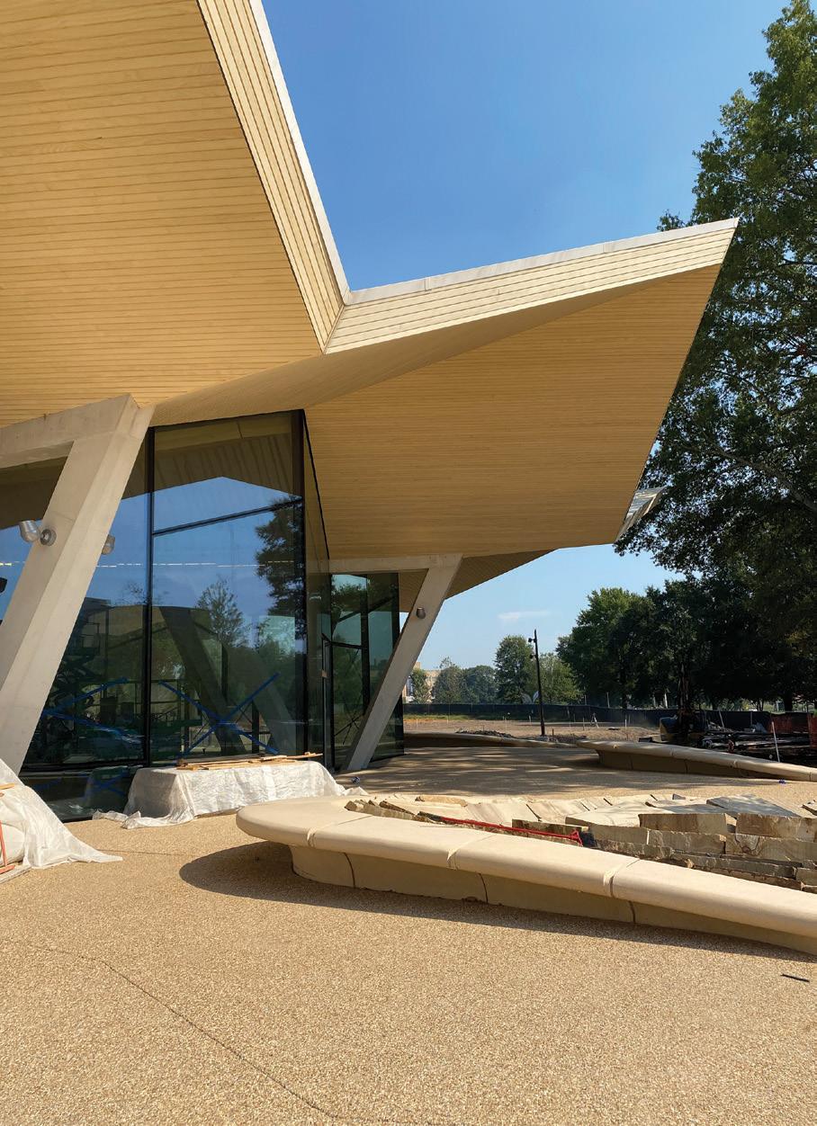
One of the early challenges during design was developing a process to model the organic folded plate roof analytically so it could be easily modified as the design evolved. The architect modeled the roof in Rhino, and the geometry included the folds, the overall roof sloping for drainage, and gentle bowing between ridges and valleys. Early in the design phase, the design team collaborated with Studio Gang to efficiently translate their Rhino model into a SAP model using Grasshopper. This translation was developed in-house by Thornton Tomasetti’s R&D incubator, CORE, and was tailored to this specific application. The Grasshopper translation created shell and frame elements in SAP that matched the architectural geometry. The shells were meshed during the translation because automatically meshing larger shell elements in SAP would have increased model run times and added complexity to the analysis. In addition, due to the number of shell elements, any design
changes to the geometry required a full retranslation of the new Rhino model due to the impracticality of manually implementing the geometry changes. Establishing an efficient translation process early in design allowed the structural team to incorporate changes quickly throughout the design process.
The design of the unique, organic structural form required an understanding of folded plate behavior and the application of basic reinforcing principles to complex geometry. The striking geometry is actually the key to the behavior of the structure. The folded plate behaves like a truss longitudinally between supports. The ridge is the top chord under compression, and the valley is the bottom chord under tension. When the roof cantilevers, the truss tension and compression chords reverse, and the reinforcement must transition to accommodate this change in stress. In the transverse direction, there is an accordion action for both gravity and lateral loads. Under gravity, the folds naturally tend to flatten out. Under lateral loads, the folds compress and expand like an accordion. This longitudinal and transverse behavior became more complex due to the organic shape.
Reinforcement of the unique shape required an established rebar layout early in the design process. The ridges and valleys set the direction of the longitudinal reinforcement. As the ridges and valleys turn and meander along the roof length, so does the longitudinal reinforcement. As multiple roof panels merge or diverge, the rebar in the slab is detailed to follow this geometry. Similarly, the transverse reinforcement was detailed always to be perpendicular to the ridge and valley, which meant very few bars were ever parallel. The local axes of each shell element were oriented to follow the reinforcement and output stresses in the appropriate directions to capture this reinforcing scheme.
The structural team applied a uniform reinforcement mat throughout the slab and used this as a lower bound
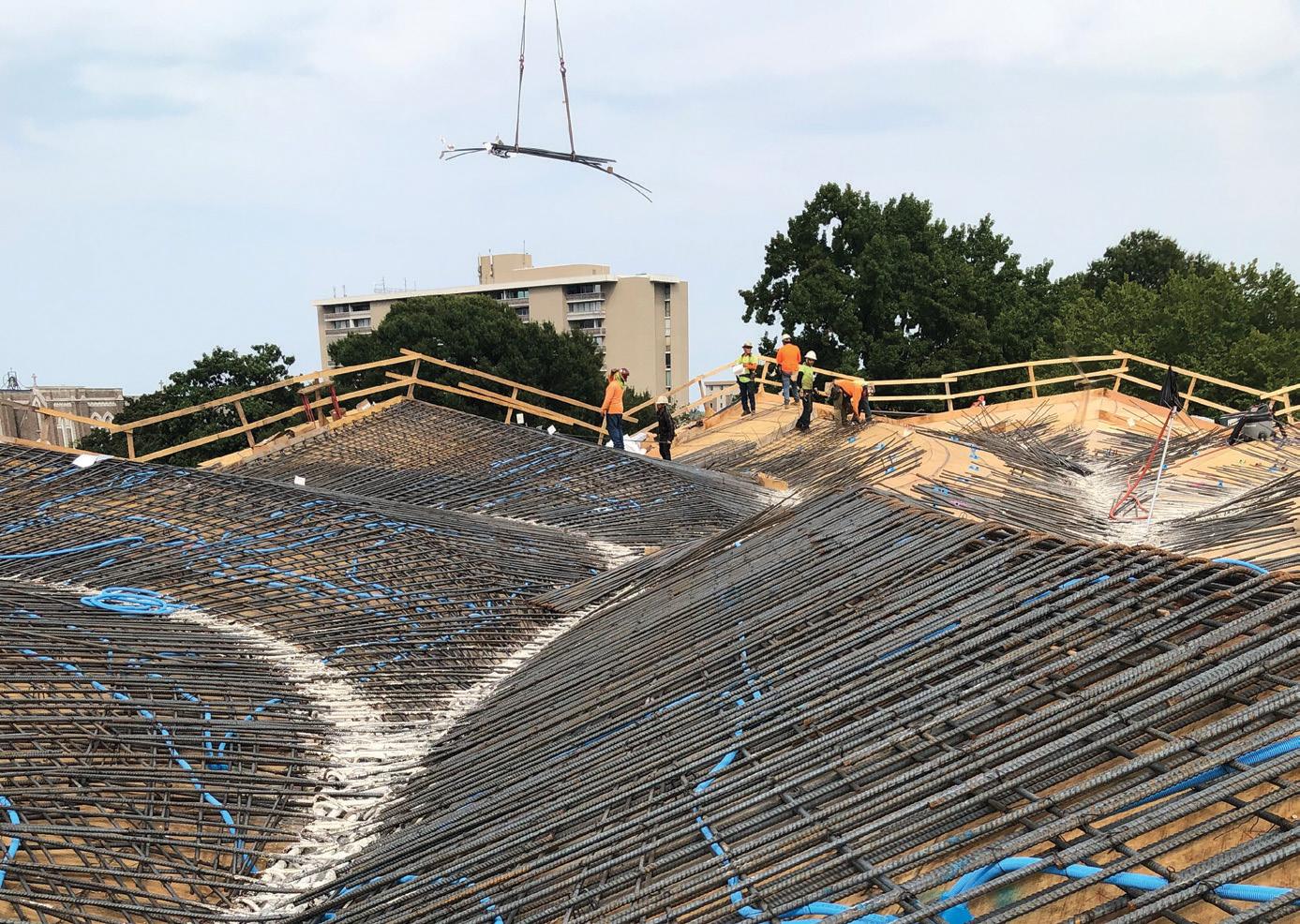
JANUARY 2023 27
Rebar placement on the Courtyard Entrance roof. Courtesy of Polk Stanley Wilcox.
The Park Entrance roof nearing completion with site work in progress. Courtesy of Polk Stanley Wilcox.
for the shell stresses. Any value above the lower bound required additional reinforcement, detailed on the structural drawings using a visual review of the shell stresses in the model. is visual review was needed because no automated tools were available for rebar design for such a complex shape.













e Courtyard Entrance structure at the north uses sloping rectangular columns supporting the elevated slab (that serves as a gathering space) and the folded plate roof. e columns form a V shape under the elevated slab, which allowed the design team to cut down on the slab spans and eliminate the need for PT on the project. Above the elevated slab, individual legs of the V extend above to support the roof at the perimeter and create an open space with no interior columns. is was possible due to the ability of the folded roof to
span long distances without supports. Sloping V columns are also used to support the roof of the Park Entrance at the south; however, their shape changes over their height. e shape is similar to a flattened V at the base of the columns and an elongated pentagon at the top of the column. is morphing shape is similar to columns designed by renowned Italian engineer and architect Pier Luigi Nervi and posed a challenge to the design team in understanding the constructability of the longitudinal reinforcement that ran through the columns. e team created 3-D models during design to understand how bars transition and move throughout the column as it changes shape. A reinforcement scheme was derived to allow continuous longitudinal bars with limited splices over the column height. As a result, all sloping columns remain architecturally exposed, which allows park and museum visitors to interact directly with the structure.






e contractor for the project was a joint venture between Nabholz, Pepper, and Doyne. Pepper Construction self-performed the folded roof concrete work. Several formwork options were explored for the construction of the folded roof structure, including CNC-milled forms. To create the intended geometry, the contractor ultimately chose to use custom wood trusses 12 inches on-center with plywood sheeting. To accommodate the formwork scheme and simplify constructability, the design team tweaked the analytical geometry of the roof, which resulted in increased rebar in some locations.

STRUCTURE magazine 28
the left with areas of blue representing additional reinforcement
On the
MAX USA Corp. • 205 Express St. • Plainview, NY 11803 • U.S.A. • Phone: (800) 223-4293 • FAX: (516) 741-3272 • www.maxusacorp.com SCAN TO VISIT OUR WEBSITE REBARTIERS WITH YEARS OF REBAR TYING TOOLS DELIVERING INNOVATION TO YOUR JOBSITE DOUBLE THE SPEED The TwinTier®’s Dual Wire Feeding Mechanism (Patented) Increases Productivity! VISIT US AT WOC Booth#: N1119 & O31258 ADVERTISEMENT–For Advertiser Information, visit STRUCTUREmag.org
Shell stress plot on
on the Park Entrance roof.
right, the resulting Tekla model shows all reinforcing steel. Courtesy of Pepper Construction and DNA Detailing & BIM.
On the left, protection was required to preserve the limestone of the original Museum of Fine Arts. On the right is the restored façade, including the replaced exterior wythe of brick. Courtesy of Polk Stanley Wilcox.
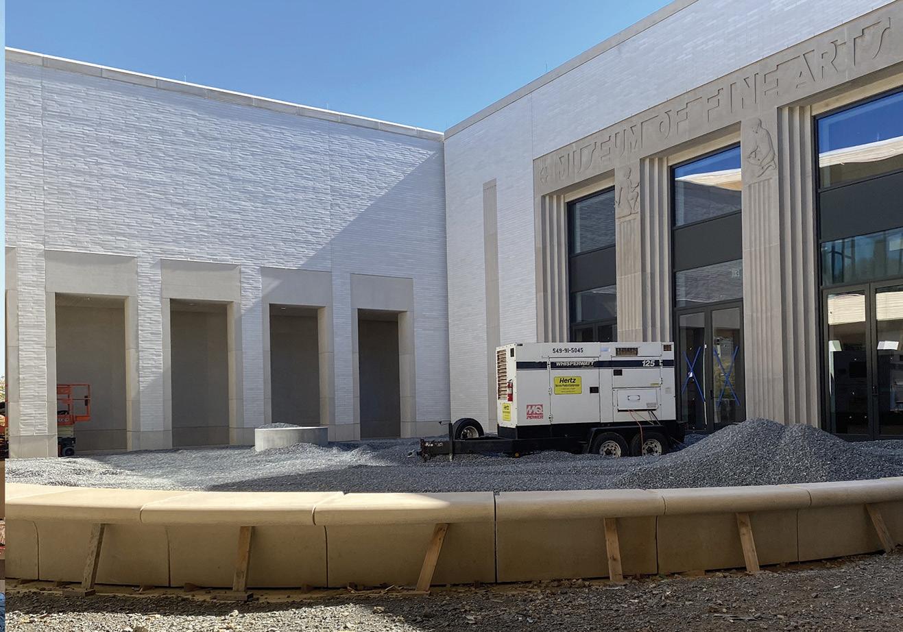
Detailing the rebar for the complex roof geometry required extensive coordination between the structural team, Pepper’s self-perform team, and the rebar detailer DNA Detailing & BIM. The reinforcement drawings were shown in 2-D on the structural design documents and supplemented with details to convey how the bars would lay out in 3-D. The detailer developed a Tekla model laying out the rebar in 3-D to validate the design intent. The Tekla model allowed the detailer to identify zones of high congestion and areas where the rebar detailing would be difficult, such as locations where multiple roof panels merged. The structural team made suggestions and rules for the detailer to follow to simplify the rebar layout while providing the required strength for the roof. The 3-D Tekla model was crucial during construction administration because it allowed all parties to confirm the bar layout before submitting shop drawings. The coordination between the structural team and concrete detailer was so successful that there was just one RFI related to bar placement in the field throughout all three roof placements.
The project presented several structural challenges in addition to the folded plate roof structure. Slicing through a collection of existing buildings constructed over a long period meant their lateral systems could be impacted. A review of the structural drawings indicated that the majority of the remaining existing building components were laterally stable, except for a one-story art school that had to be laterally connected to new shear walls.
The new gallery space on the second floor next to the main entrance to the north saw significant structural modifications to the existing structure and required creative solutions. The laterally independent structure was initially designed as a tall single-story space with a stepped roof. The new design added a second level to create the gallery space, and a flat roof was created by raising the existing stepped roof in some areas and lowering it in others. The design team was able to re-use and maintain, in place, many of the structural elements of the existing gallery. The original gallery was designed as a moment frame structure with tall columns designed to resist lateral loads. The structural team added new braced frames converting the structure from a moment frame to a braced frame system. This allowed the reserve capacity of the columns to be used to support the additional floor. In addition, the new floor also reduced the unbraced length of the tall columns, further improving their ability to support new gravity loads. Existing footings were checked and enlarged to support the new gallery loading where needed. Micropiles were used to increase the capacity of the footings at the new braced frame locations.
The current design included several changes to the original 1937 Museum of Fine Arts. First, part of the existing second floor was removed to create a double-height atrium when guests enter the museum – this required new lateral bracing for the unreinforced masonry piers that make up the entryway. In addition, new openings were cut in the museum’s walls, which impacted the structure’s lateral capacity. The structural team tracked the change in demand and capacity to confirm it stayed within the International Existing Building Code limitations for renovations to existing structures. A prominent change to the building was the restoration of the original façade. The exterior walls are four brick wythes thick, and the exterior layer required replacement for aesthetic reasons. Since the building uses the exterior walls as part of the gravity and lateral system, removing brick impacts the load-resisting capacity. The structural team developed a sequence of removing and replacing the brick to limit the change in capacity in the temporary state and maintain the wall’s capacity in the final state.
The reimagined AMFA has dramatic changes both inside and out. The folded plate roof creates an incredible presence in MacArthur Park, which can also be felt in every room of the museum while maintaining the historic integrity of each addition. The world-class space will give the client and Little Rock a platform to showcase everything they offer for years to come.■
Ben Sexton is a Senior Project Engineer at Thornton Tomasetti, Inc. (bsexton@thorntontomasetti.com).
Faz Ehsan is a Managing Principal at Thornton Tomasetti, Inc. (fehsan@thorntontomasetti.com).
Project Team
Structural Engineers: Thornton Tomasetti, Inc.
Façade Engineers: Thornton Tomasetti, Inc.
Architect of Record: Studio Gang
Associate Architect: Polk Stanley Wilcox
Contractor: Nabholz Construction, Pepper Construction, and Doyne Construction Co.

Concrete Contractor: Bass Concrete
Folded Plate Concrete Contractor: Pepper Construction
Rebar Detailer: DNA Detailing & BIM
Steel Fabricator: W&W Steel | AFCO Steel

JANUARY 2023 29
construction ISSUES
Tendon Tail Cutting
Is the Process Compromising the Service Life of Encapsulated PT?
By Kent K. Sasaki, P.E., S.E., and Kaat Ceder, P.E.
U
nbonded post-tensioned (PT) concrete slab construction is commonly used for many types of structures, from highrise towers to low-rise concrete podiums and parking structures. Since the adoption of ACI 318-14, Building Code Requirements for Structural Concrete and Commentary, many jurisdictions now require fully encapsulated PT tendons for building applications in all environments to prevent moisture intrusion and improve durability. The effectiveness of full encapsulation, however, can be highly dependent on the PT system installation, specifically the cutting of the tendon tails. This operation may not be done with enough precision and care to protect the grease caps, which encapsulate the tendon tails and complete the PT system’s continuous moisture barriers.
Across several projects in the San Francisco Bay Area, the authors have observed a large number of opened PT stressing end pockets with a variety of installation defects, all leading to incomplete encapsulation of the PT tendon and making the PT system vulnerable to future corrosion. All of the observed defects were related to the installation of the PT system. Of those observed deficiencies, most were related to the improper cutting of the PT tendon tail.
Figure 1. Typical components of a single-strand encapsulated PT tendon at the stressing end anchorage.
the use of encapsulated tendons is required by code in many states and jurisdictions.
A review of articles and papers on installation issues with encapsulated PT systems, and discussion with engineers outside of California, indicate that these problems are occurring not only in the San Francisco area but all over the country.
Background
ACI 423.7-14, Specification for Unbonded Single-Strand Tendon Materials, requires the use of encapsulated tendons for all applications governed by ACI 318 (such as elevated slabs and beams). Previous versions of the document required encapsulation only in aggressive environments. Since ACI 423.7-14 is now referenced by ACI 318-14,
At the stressed end of the tendon, the two main elements of the encapsulation system are the polyethylene-coated anchor and a plastic encapsulation cap (herein referred to as the “grease cap”) that is placed on the strand tail after it has been cut to the proper length (Figure 1). The grease cap must fit snuggly in the metal ring of the anchor because this seal provides the watertight connection.
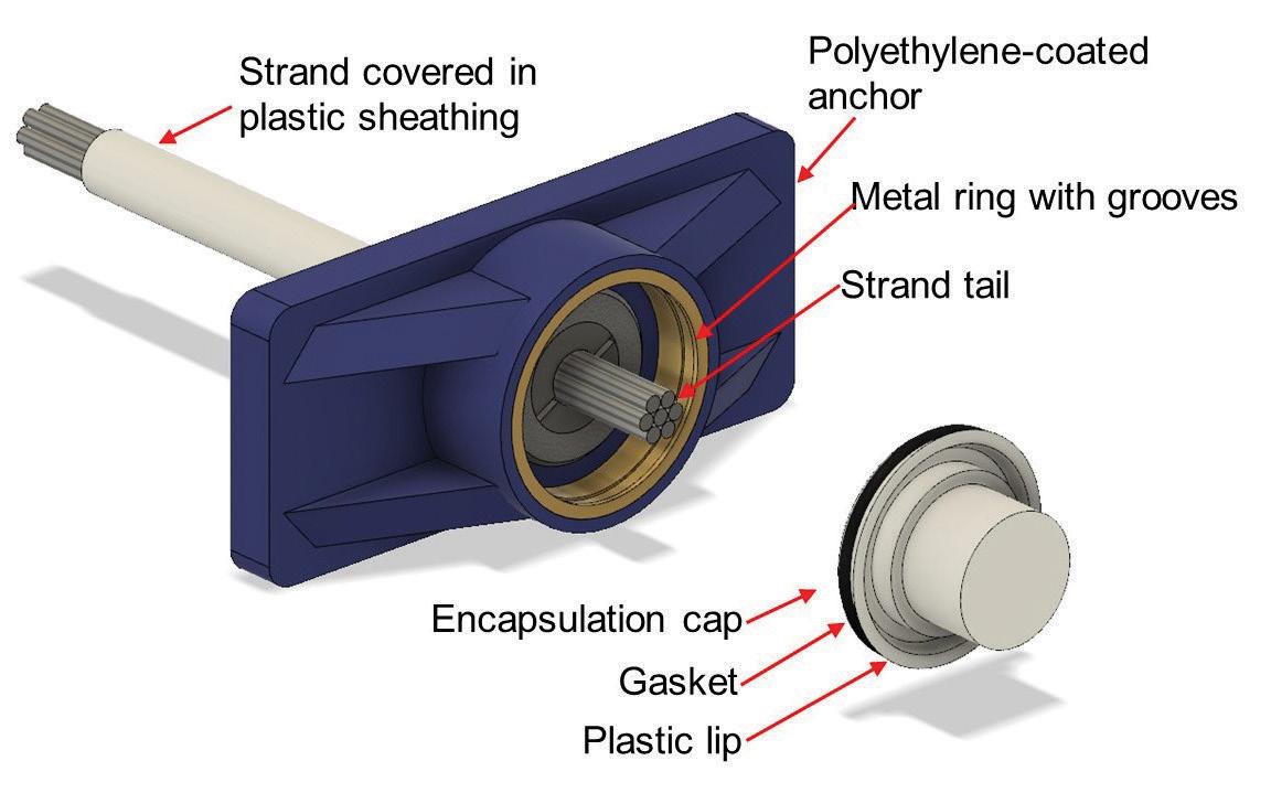
There are generally four techniques to cut tendon tails: an oxyacetylene torch, abrasive wheel, hydraulic shears, and gas plasma cutters. In the authors’ experiences, the use of an oxyacetylene torch (herein referred to as “torch”) is the typical method used at most construction sites unless another method is specified by the engineer-of-record in the contract documents (Figure 2). No industry standard currently specifies which cutting methods should be used.

However, the geometry of the small formed stressing pocket limits the positioning of the torch and torch visibility of the tendon and the stressing end anchorage by the operator. This increases the potential for damage to the stressing end anchorage and the tendon tail not being cut to the appropriate length ( Figure 3 ). Proper tail lengths are addressed in the Post Tensioning Institute’s manual – PTI M10.3-16, Field Procedures Manual for Unbonded Single Strand Tendons .
Field Observations
The authors observed over 800 opened stressing pockets across two San Francisco Bay Area buildings with PT concrete slabs. The observed opened pockets comprised a large majority of the total number of stressing pockets in each building. All of the structures observed were built after the adoption of the 2016 California Building Code, which adopted ACI 318-14 and therefore required encapsulation of the PT tendons. In each case, the tendon tails were reportedly cut using
STRUCTURE magazine 30
Figure 2. Cutting a tendon tail using an oxyacetylene torch.
torches. Of the more than 800 pockets observed, over 50% exhibited one or more of the conditions described below that could compromise the tendon encapsulation.

e conditions observed at these stressing end anchors can be generally grouped into the following categories. Figure 4 shows an example of each category.
1) Tendon tail too long: If the tendon tail is not cut short enough, the grease cap cannot be fully seated and provide the required seal. Frequently this results in the tail also puncturing the grease cap, promoting moisture ingress. is condition was observed at more than one-third of the opened stressing pockets.
2) Tendon tail too short: If the tendon tail is cut too short, the tendon tail may not puncture the temporary plastic seal holding the grease inside the grease cap.
3) Molten and deformed anchorage ring: Prolonged and elevated temperature exposure to the torch flame within the confined space of the formed stressing pocket melted or deformed the anchor ring and prevented the proper seating of the grease cap.
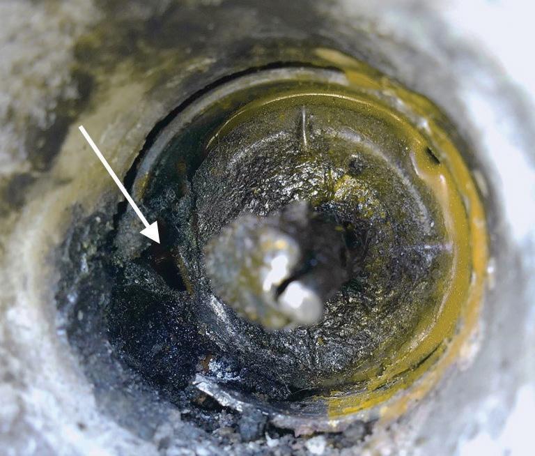


4) Debris in anchor ring: Debris in the metal ring, whether molten metal or plastic, impedes the seating of the grease cap. Often this debris can be from the cutting operation, and the condition may coincide with Category 3.
All four of these categories can reasonably be attributed to the difficulty of positioning a torch inside the small, formed stressing pocket and the limited visibility of the anchorage components during the cutting operation.


Recommendations


Based on field observation of opened stressing pockets in several existing recently constructed elevated concrete slabs in the San Francisco
Bay Area, the authors observed defects that have compromised the encapsulated PT system. is would make the encapsulated system vulnerable to moisture ingress and future deterioration. Many of these defects can be attributed to using an oxyacetylene torch to cut the tendon tails and the constrained geometry of the formed stressing pocket. Several practices could be implemented in both the design and construction of the encapsulated PT systems to reduce the likelihood of these installation defects discussed above.
1) Specify tendon tail-cutting methods that do not include the use of an oxyacetylene torch in the construction documents. Alternatives include hydraulic shears or plasma cutters.
2) Ensure that qualified inspectors observe the stressing anchorages before and after the installation of the grease caps and confirm that nothing is impeding a good seal and full encapsulation.

3) Provide adequate work platforms that allow individuals to be in a good working position to cut the tendon tails. For example, provide a platform where an individual can stand upright while cutting the tendon tail rather than leaning over the edge of the slab to cut the tendon tail. In addition, PT anchorage manufacturers could assist in achieving and promoting best practices for the installation of encapsulated PT systems in some of the following ways:

1) Discouraging the use of oxyacetylene torches to cut PT tendon tails for their products.
2) Develop tendon tail encapsulation alternatives that are less likely to be compromised by typical construction practices.
3) Provide repair options and procedures for typical damage to encapsulated PT systems.
4) Actively participate in professional organizations to help develop standards for inspecting, installing, and repairing encapsulated PT systems.■
Kaat
JANUARY 2023 31
Figure 3. Rendering of the torching of the tendon tail in section. Tendon tail length tolerances are based on PTI M10.3-16.
1) 3) 2) 4)
Figure 4. Examples of Category 1) through 4) as described in the Field Observations section of the article (clockwise from top left).
Kent Sasaki is a Principal at Wiss, Janney, Elstner Associates, Inc. in Emeryville, California (ksasaki@wje.com).
Ceder is an Associate III at Wiss, Janney, Elstner Associates, Inc. in Emeryville, California (kceder@wje.com).
7 Key Benefits of Fiber-Reinforced Concrete
By Michael Mahoney, P.E.
As a result of the global pandemic, construction materials such as steel – a necessary material for use in traditional concrete applications – have been impacted by price increases and material shortages. Although this may be concerning for businesses and municipalities undertaking construction projects involving parking decks, roads, bridges, and other concrete-related repairs, it may open up the opportunity to utilize the short-term and long-term benefits of fiberreinforced concrete.
Selecting Fiber-Reinforced Concrete
Fiber-reinforced concrete (FRC) is a concrete mixture reinforced with randomly oriented fibers. Depending on the project and the environmental impact that may affect the concrete, there are a wide variety of fibers (https://bit.ly/3nMQ91H) that may fit the needs of a specific project.
Examples of some available fibers include:
• Synthetic Macrofibers: Used in applications to replace conventional reinforcing for flooring, precast, and shotcrete applications
• Steel Fibers: Generally used to provide concrete with enhanced toughness and post-crack carrying capacity
• Steel and Micro/Macro Blends: A combination of steel and/ or macro-synthetic fibers with various micro-synthetic fibers that help control plastic shrinkage cracking while also providing enhanced toughness and post-crack load carry capacity
• Glass Fibers: Predominantly used in architectural applications and modified cement-based panel structures
• Cellulose Fibers: Processed wood pulp product that is used for the control and mitigation of plastic shrinkage cracking
Over the past several years, there has been increased interest in fiber-reinforced concrete in concrete pavement applications, such as parking lots, bridge decks, and roadways. As a result, organizations like the American Concrete Institute, the American Concrete Pavement Association, and the National Concrete Pavement Technology Center have developed guidelines and recommendations on properly selecting and using fiber in concrete.
FRC is Widely Utilized
While it may seem like a new development in construction, fiberreinforced concrete has been around for several decades. However, as municipalities and businesses seek a low-cost option that provides durability and the ability to develop state-of-the-art designs, there has been a rise in the use of fiber-reinforced concrete.
For example, SoFi Stadium – the home stadium of the Los Angeles Rams and Chargers – used synthetic macrofiber reinforcement for its topping slabs and crack control. In addition, a concrete overlay with fiber reinforcement was used to rehabilitate 15-lane miles of highway in Fowler, Indiana.
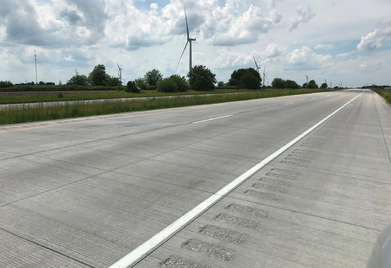
Key Benefits of FRC
Here are the seven key benefits of fiber-reinforced concrete that both designers and customers should consider:
• Cost-Effectiveness: According to the National Concrete Pavement Technology Center, “fiber-reinforced concrete can offer a cost-effective, sustainable solution for resurfacing and rehabilitating existing pavements. Either as overlays or full-depth replacement pavements, state DOTs and other engineering groups are rapidly adopting macro-synthetic fibers into their designs, specifications, and experimental projects for road and airfield pavements.”
• Fewer Staff Required: With the limitations on available manpower and cost uncertainties affecting the construction industry in today’s economy, fiber-reinforced concrete can offer

STRUCTURE magazine 32 guest COLUMN
Full-depth concrete paving with macrofibers in Ohio.
Concrete overlay with macrofibers in Indiana.
a safer and more cost-effective working environment that can actually speed up construction while reducing the environmental impact at a project site. From the perspective of safety, fewer personnel on-site and reduced trip hazards are significant benefits and allow for increased placement speed.
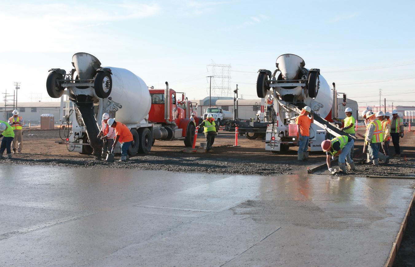
• Reduced Delays: By subtracting the use of conventional steel rebar, an inspection of the steel placement is not required by a municipality. The concrete would be placed with fiber reinforcing supplied by a concrete provider and installed in the concrete prior to placements. Ready-mix trucks can quickly and efficiently place the concrete at the required project location with minimal finishing practices.
• Improved Long-Term Serviceability: Concrete can be susceptible to corrosion, freezing and thawing, attacks by traditional road salt, and penetration of other aggressive solutions. Concrete durability can be improved by minimizing the ability of water and other solutions to penetrate beyond the surface. Fiber-reinforced concrete helps maintain tight crack control, reducing the size of a crack’s width – ultimately preventing water and other solutions from penetrating the concrete. It is important to note that synthetic fibers for concrete do not corrode. Removing conventional steel from concrete, which can corrode and cause accelerated deterioration, is a significant advantage for synthetics as they are designed to be equivalent from an engineered performance perspective. Although steel fibers generally do not corrode either, they can discolor at a surface exposed to air or water. As such, this offers an aesthetic advantage for synthetic fibers.
• Temperature and Shrinkage Reinforcement: Fiber-reinforced concrete can be an economically viable alternative to welded wire reinforcement and small diameter bars to guard against temperature and shrinkage issues.
• Reduced Cost: Fiber-reinforced concrete can reduce construction times, reduce the cost of labor, and lower maintenance costs, which are beneficial for contractors. Those savings can then be passed along to customers through reduced costs for the completed project.
• Environmentally Friendly: Like old tires and athletic footwear recycled into synthetic athletic turfs, fiber-reinforced concrete can serve as an environmentally friendly solution. Steel or synthetic fibers offer a longer service life for concrete
Blend of synthetic microfibers and macrofibers for concrete applications.

than conventional steel bar reinforcement. Research has shown that recycled steel fibers, made from materials like recycled car tire rims, can provide similar performance to traditional steel fibers – but at a fraction of the cost. In addition to cost savings, these fibers help minimize landfill waste. Furthermore, fibers make the concrete more durable and ultimately lead to a longer lifecycle, thus reducing the overall environmental impact.
Limitations of FRC
In addition to the seven key benefits of fiber-reinforced concrete outlined above, it is also important to consider the potential limitations of this product as research and development continue to be conducted across the concrete industry.

For instance, fiber reinforcement is still not yet able to replace heavy structural concentrations, such as those for bridge girders and columns. With this in mind, other materials and hybrid solutions will continue to be considered, and more composite concretes will be developed over the coming years. In addition, fiber-reinforced concrete may also require special considerations when it comes to mixing and consolidation. However, this can be easily managed through consultation with the various manufacturers who are involved.
As the uncertainties of the economy remain, fiber-reinforced concrete serves as a viable solution to protect the health and safety of construction personnel and the financial bottom lines of businesses and municipalities.
■
This article, all or in part, was previously published in Concrete Contractor, September 2021. It is reprinted with permission.
More information on SoFi Stadium and the rehabilitation of the Fowler, Indiana, highway, respectively, can be found at the following links:
https://bit.ly/3IfYSmy https://bit.ly/3Rh8qSG
(mmahoney@euclidchemical.com).

JANUARY 2023 33
Warehouse construction in Arizona using synthetic macrofibers.
Michael Mahoney is a Professional Engineer and Director of marketing and technology for fiber-reinforced concrete at Euclid Chemical. He is a fellow and member of the American Concrete Institute and has served on various committees for the National Pre-Cast Concrete Association and American Society for Testing and Materials
We’re All In. How About You?
DCI Engineers is a proud signatory firm of the SE 2050 Challenge—a commitment to net zero structures by the year 2050.
It’s an exciting time to be an engineer! Coupled with decades of green certified design experience, our team members are using the latest tools and technologies to apply sustainable solutions for the built environment. These include:

» Life-Cycle Assessment
» Embodied Carbon Tracking » Optimized Material Use » Reduced Carbon Materials » Material Re-use Evaluation
» Mass Timber Design
» Modular and Prefabricated Design
WHO WE ARE
Now more than ever, we as engineers have a responsibility to provide real, applicable solutions for a greener future. We invite you to join us!
CERTIFIED PROJECTS
Living Building Challenge, USGBC LEED, Seattle Deep Green Pilot, Green Globes, Net Zero
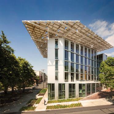


Learn more about the SE 2050 Challenge by visiting se2050.org or connect with DCI’s Sustainability Group at dci-engineers.com/markets/sustainable-design.
We are a 22-office, nationwide firm providing civil, structural, rightof-way, industrial & bridge engineering services. DCI is licensed and building in all 50 States, providing our clients regional expertise backed by national experience. Our portfolio expands over a dozen markets, ranging from mass timber and modular construction to seismic/adaptive renovations to highrise Performance Based Design and everything in between. We employ over 380 of the most dedicated technical and support staff in the industry and continuously seek out new methods and technologies that support the vision of our clients. Since 1988, DCI has been focused on providing Service, Innovation & Value—a belief that how you work with people is as important as what you do for them.

STRUCTURAL | CIVIL | AND MORE!
Headquarters
818 Stewart Street, Suite 1000 Seattle, WA 98101
www.dci-engineers.com
Scan to learn more about sustainability at DCI Engineers
STRUCTURE magazine 34 ADVERTORIAL Profile STRUCTURAL ENGINEERING FIRM
60+
just the FAQs
FAQs on ASCE Standards
What You Always Wanted to Ask
By Laura Champion P.E., F.SEI, F.ASCE, and Jennifer Goupil, P.E., F.SEI, M.ASCE
This quarterly article answers some of the questions received from engineers, building officials, and other design professionals about structural standards developed by the Structural Engineering Institute (SEI) of the American Society of Civil Engineers (ASCE). Questions such as these are often considered to develop future editions. Following are some questions received and SEI’s responses.

ASCE/SEI 7
When will the IBC require ASCE 7-22 tornado loads?
Q: Our office has been educating ourselves about the new tornado load provisions, and we are curious about when we will start to use them. When will ASCE 7-22, Minimum Design Loads and Associated Criteria for Buildings and Other Structures, be adopted into the International Code Council’s (ICC) International Building Code (IBC) and be required by my jurisdiction?
A: The easy, short, partial answer is that the 2022 edition of ASCE 7 has been approved for adoption into the 2024 editions of the ICC’s I-Codes, including the IBC and the International Existing Building Code. The ICC’s Code Development Cycle for the 2024 Codes concluded in 2022. The development cycle includes two hearings: the Committee Action Hearings in March and the Public Comment Hearings in September, followed by an online government consensus vote. The longer answer to the second part of the question regarding your jurisdiction – it is up to your jurisdiction. Some jurisdictions adopt the most recent updated codes as they are published; however, many do not. Please check with your specific jurisdiction regarding the adoption of the 2024 IBC and further confirm the inclusion of the tornado provisions requirements. One additional comment regarding the use of the provisions; it is always possible and often appropriate to work with your clients and the jurisdiction to use ASCE 7 provisions prior to adoption by the jurisdiction. This can be done at the jurisdiction level or per-project basis.
What is the correct load required on intermediate rails?
Q: ASCE 7-16 Section 4.5.1.2 Guardrail System Component Loads discusses the loading on guard infill material. The section states, “Balusters, panel fillers, and guardrail infill components, including all rails except the handrail and the top rail, shall be designed to resist a horizontally applied normal load of 50 pounds on an area not to exceed 12 inches by 12 inches, including openings and space between rails and located so as to produce the maximum load effects.” Is it correct to interpret that Section 4.5.1.2 allows the distribution of a 50-pound load over a 12-inch by 12-inch area of the infill components, meaning that each individual member receives its distributed portion of the load, not a 50-pound load on each infill member?
A: Yes, that is correct. The 50-pound load should be distributed to each member that crosses the 12-inch by 12-inch square cited in the provisions within the area of contact of the 12-inch by 12-inch square. In the case of spaced vertical framing, the load would be distributed to each vertical element that passes through the 12-inch by 12-inch square, as indicated in your request. While the total load resisted by
all such members is 50 pounds, the load on any one vertical framing element would be less than this.
What is the wind load on a temporary tent structure?
Q: I am a building official. I am reviewing a design for a large tent structure for which the design professional used ASCE 37-14 Design Loads on Structures During Construction to reduce the loads on the temporary structure. The tent will have removable wall components that will only be installed in case of bad weather, but I cannot find any guidance in ASCE 37 regarding removable components. How should the wind load on the tent walls be accommodated in addition to without the walls?
A: First, the design team is using the wrong standard. ASCE 37 is only applicable for calculating lower, temporary design loads that would be applied during construction. These lower loads are justified in ASCE 37 because of the controlled occupancy of a construction site – in other words, for a structure that is not accessible to the public. ASCE 37 is not the correct document to use for temporary structures that are accessible to the public.
That said, there is a gap in the provision of ASCE 7 Minimum Design Loads and Associated Criteria for Buildings and Other Structures for lower loads for temporary structures. However, the good news is that an ad hoc committee of experts worked for two years to develop provisions submitted for adoption into the 2024 IBC to fill this gap. As a result, the new IBC Section 3103 Temporary Structures was developed by a large stakeholder group – including ASCE 7 members, ICC Committee members, building officials from large jurisdictions such as New York City, San Diego, Seattle, and Las Vegas, the Entertainment Services and Technology Association (ESTA), and National Council of Structural Engineers Code Advisory Committee members – to align with the design basis for IBC Chapter 16 and ASCE 7, to provide the appropriate level of risk and structural reliability to the public. Given a favorable outcome of the ICC process, this new section and related definitions and pointers will be included in the 2024 IBC.
Following this effort in the IBC, the next step is to include loads on temporary structures provisions into the 2028 edition of ASCE 7, and the committee will work to do just that. Then there will be a consistent, reliable approach to use for the design of temporary structures. Until then, temporary structures should be designed in accordance with IBC Chapter 16 and ASCE 7 unless the jurisdiction permits otherwise.■
If you have a question you want to be considered in a future issue, send it to sei@asce.org with FAQ in the subject line. Visit asce.org/sei to learn more about ASCE/SEI Standards. Please see the disclaimer included in the online version of this article at STRUCTUREmag.org

JANUARY 2023 35
Laura Champion is a Managing Director of the Structural Engineering Institute and Global Partnerships at the American Society of Civil Engineers.
Jennifer Goupil is the Director of SEI Codes, Standards, and Technical Initiatives at the Structural Engineering Institute of the American Society of Civil Engineers.
Drones in Practice
Changing the Way Engineers Work
By Zane Pucylowski and Chad Conley
Engineers are constantly trying to find new ways to optimize processes to perform their duties more effectively. Implementing drone or Unmanned Arial Vehicle (UAV) technology in their projects is one solution engineers have found over the past few years and are starting to use.
Drones used in engineering are a great way to enhance practices, cut costs, streamline processes, and increase efficiency. These UAVs are valuable tools in many ways, giving engineers a multi-dimensional utility across the specialties.

Improving Infrastructure
Managing physical assets is a key component of using drones in the field. Engineers piloting a drone can perform manual inspections and site surveys without being on-site. Drones with additional features like live stream capabilities allow engineers, project managers, developers, and superintendents to stay fully informed when working off-site.
Programs can be downloaded to provide access to multiple individuals working on any given project. These programs allow pilots to fly the drone over the worksite and tag issues for workers and contractors to assign tasks. In turn, these workers can comment back on the viewing application in real time with the team.
Inspecting work sites with a drone ensures workers can be proactive in building or improving infrastructure and help prevent deterioration. For instance, a drone equipped with a thermal camera can identify areas strained by weather or leaks. These cameras instantly visualize temperature ranges throughout the structure and allow engineers to see damage that might otherwise go unnoticed, allowing workers to fix the issue before it becomes dangerous.
Improving Workflow
Drones can save a significant amount of time when replacing existing processes. For example, engineering firms can save time and money by doing site measurements once, then using digital models created from the information provided by the drone instead of making repeated trips to the site.
Many engineering firms have traditionally used helicopters to get aerials on a project.
However, these flights can cost anywhere from a few thousand dollars to $20,000 per flight to capture the videos necessary to map the project. Today, drones at a fraction of the price provide engineers with the videos they need and data on topography, heat signatures, and water levels. In addition, new technology is constantly improving workflow, such as photogrammetry, creating marketing material, and site monitoring.
Adding drones to an engineering firm’s arsenal of tools boosts the productivity of those working on the project and provides the information needed to keep the project on track.
Mapping Job Sites
Innovations in drone software allow engineers to produce detailed 3-D maps and models using the data the drone captures. This accurate site data can cut costs because the visualizations help teams plan their activities and reduce the risk of design errors that may require reworking. For example, when engineers work on a new job site where the ground has yet to be broken, drones can fly over the area and capture the terrain. This mapping allows engineers to know where to focus leveling, locate flood basins, and anticipate any difficult-to-dig material below the surface, thus saving time and money. All engineers need to do is place ground control points throughout the site and fly the drones. The drones capture the area, and the engineers can inspect the topographic surveys.
The 3-D maps that drones create can be combined with an analytics platform allowing engineers to communicate the data to the entire team. Improved digital mapping also means every team member is aware of the site’s landscape and is working with the same information. Instead of taking days or even weeks to walk the site, engineers can fly the drone to provide a field-to-finish solution for the mapping process.
Structural Engineering Benefits
Structural engineers often use drones to inspect those hard-to-reach places. Engineers use UAVs to collect photos, enabling a precise assessment of the existing conditions of skylights, roofs, bridges, and culverts.
Structural engineers find drones to be very beneficial in documenting existing conditions of areas like bridges. For example, if there is a need to scan a bridge, drones not only create an accurate representation of the bridge but also shorten the time it usually takes.
Another area that drones are beneficial for is when surveying a property, especially if the terrain is rough. Using a drone requires no boots on the ground walking through hazardous locations. Instead, the drone operator can mark points, create a 3-D model of the area, and share that data with the engineering team using point cloud technology.
Keeping Track of Progress
Staying on time and under budget is vital to the success of any engineering firm. All projects need to operate on a timeline, and engineers are tasked with ensuring the timeline is kept.
Drone flyovers show the progression of the project site. Engineers can compare the initial map of the site with an up-to-date flyover of the site. Comparing these different photos and videos gives engineers insight into what has been done on the site, what needs to be done, and what areas may need additional work. In addition, these images help engineers monitor the project and ensure the schedule is kept. It also reduces the time engineers need to spend on the job site.
Cameras and Sensors
Engineers can attach cameras and sensors to drones, including optical gas imaging to detect gas leaks and multispectral imaging sensors to study land usage.
Light detection and range (LiDAR) scanners are among the most popular attachments for engineers. LiDAR captures hundreds of square miles a day. These scanners measure
TECHNOLOGY STRUCTURE magazine 36
up to 80 separate points per square meter, creating a very detailed digital model of a landscape. The accuracy of LiDAR allows the scans to be used in 3-D models in all aspects of design, planning, and decision-making. LiDAR sensors can also see through dense areas to capture the earth’s structure that even satellites cannot see.
Photogrammetry cameras make it possible to record objects with more than one image. This allows for 3-D reconstruction, where the shape and position of an object are taken by measurements in the image. The reconstruction occurs through a non-contact recording, image interpretation, and model evaluation.
Richer Results
5G wireless networks are being built across the country and the world. Drones with 5G capabilities are coming to the market quickly, and this new technology allows for new capabilities. Virtual reality usage with drones is a crucial area that benefits from this new form of data transfer. An engineer connected to a virtual reality setup can be miles away in the office controlling the drone at the work site. They only need someone to take the drone outside and turn it on. Once it is up and running, the engineer back at the office has complete control of the drone to do whatever task is needed.
The main benefits of 5G-capable drones include low latency, rapid data transfer, realtime analytics during flight, and up to a million connected devices per square kilometer for easy communication with multiple people.
Sharing the Data
Visual communication helps engineering teams stay up to date on projects which is critical for success. Many engineering projects have multiple shareholders and companies working together to achieve one goal. Whether a private or government contract, engineers want to stay connected with offsite workers and other leaders on the project. Drones simplify sharing data collected on a project with all parties.
Sending handwritten updates is now a thing of the past. Drone imaging provides comprehensive details to all those involved. Many people associated with the project are often too busy or far away to make regular trips to the site, so having a drone to provide aerial data, maps, and videos makes communication much more effortless.

Each image or video shared includes metadata for easy documentation. This data allows the organization and access to specific points that an engineer needs to find quickly. For instance, each time the drone records during
a flight, it creates a file that metadata can search. These files can be searched by time, date, and other information. Most commercial drones have high-end software allowing engineers to include the information they need in the metadata.
Drones are also an excellent way for project leaders to provide team members with information. For example, rather than getting on a call and telling the on-site workers where the issues are, they can provide visual data from the drone footage to communicate a problem that needs addressing.
Easily shareable data is essential in keeping projects on task and everyone in the know about what is happening on-site. Drones make this process easier and more accessible for all of those involved.
Maintaining Site Safety
According to the Occupational Safety and Health Administration (OSHA), falls were the number one cause of injury and death in the construction industry in 2019. Engineering and construction companies are understandably concerned with any injuries occurring on job sites and are always looking for ways to minimize these risks.
Flying a drone removes the danger of having people climb high structures or needing helicopters to survey the worksite. Drones can survey dangerous areas and take engineers and other workers out of the high-risk areas where these injuries typically occur.
Drones are piloted from a distance and often away from the work site, which is essential when working in areas too dangerous for people. For example, many factories have hazardous or flammable materials that workers should not encounter. Instead of sending out engineers to work in these areas, drone operators can stay at a safe distance while the drone flies over the area to collect data. This saves the engineering firm time and money and minimizes the risks to the workers.
Drones also reach heights not available to humans climbing the structures. Drones can reach the optimal vantage point of a project and provide detailed inspection records and safer environments for workers.
Reducing Workers’ Compensation Claims
According to OSHA, employers pay almost $1 billion weekly for workers’ compensation costs. This outlay includes payments, medical expenses, and legal services. In addition, there are many indirect costs the employer must pay, including training replacement employees, lost productivity, lower employee morale, repairs, and accident investigation.
As mentioned previously, drones can help improve worker safety. Improving worker safety decreases the frequency of on-site incidents and saves engineering firms and construction companies from paying high workers’ compensation costs.
Licensing and Laws
Flying a drone for commercial use in the United States requires a Remote Pilot Certificate from the Federal Aviation Administration (FAA). Operators applying for a certificate must be able to read, speak, and write in English, be in a mental and physical condition to fly the drone safely, and be at least 16 years old. Operators must also pass an Aeronautical Knowledge test at an FAA-approved testing center and undergo a security screening through the Transportation Safety Administration.
Laws for operating drones vary by state, so it is essential to contact the state’s Department of Transportation to ensure compliance.
The increased use of drones correlates with an increase in possible property damage, bodily injury, and other liability issues. However, the FAA lacks protections for liability caused by drones. For example, there are no regulations regarding whether a commercial company, a pilot, or a drone manufacturing company is liable when a drone crashes.
There are many laws regulating the commercial use of drones. It is best to speak with your insurance agency and the state’s Department of Transportation beforehand to ensure the drone is being used properly.
Utilizing drone technology for engineering projects can ensure that projects remain under budget and on time. Drone data helps reduce the hours spent on time-consuming tasks like inspections and expedites daily processes. By allocating labor and resources to the most critical assignments, engineers can prioritize their duties and create an efficient working environment. Engineers equipped with the latest technology, like drones, can make better-informed decisions for their firms and the job at hand.
■
Zane Pucylowski is the President and Principal Engineer at Phoenix Engineering and Consulting, Inc. in Woodstock, Georgia. He is also a part-time faculty member teaching senior design in the Mechatronic Engineering department at Kennesaw State University.
Chad Conley is the CEO of Complete Roofing in Woodstock, Georgia. Conley is certified by the FAA as a Commercial Drone Operator and has a private pilot’s license through the FAA.
JANUARY 2023 37
Maryann Phipps, S.E.
Maryann Phipps has worked as a structural engineer for 40 years, evaluating, designing, and renovating buildings in California. She is an active leader in the engineering community and a regular speaker on earthquake performance and the seismic protection of non-structural building components. In 2022, she was inducted into the National Academy of Engineering. She received the H.J. Brunnier Lifetime Achievement Award from the Structural Engineers Association of Northern California in 2020, serving as the organization’s first female President in 1993.
She founded Estructure in 2000 to provide specialized and client-focused structural engineering services for public and private clients wishing to address earthquake hazard risks. Her firm specializes in complex building projects focusing on health care and laboratory renovations, seismic evaluations and retrofits, interior renovations, and infrastructure improvements.

After many years in the industry, you decided to start your own company. What compelled you to do this? What lessons did you learn that our readers would benefit from?
I never intended to start a firm! I was happily working at Degenkolb Engineers and was a Senior Principal there. However, after
18+ years, I left for a few reasons: 1) I did not have enough time to spend with my two children, 2) I am a “hands-on” engineer who loves getting dirty on job sites, working directly with clients, and knowing every aspect of a project which can be hard to do in a large firm; and 3) I wanted to have more than one professional experience in my life. So, when I left, I started working solo out of my house. Growing a firm started organically several years later.

The lesson , from my perspective, is to check in with yourself and ask if what you are doing feels right. Of course, there are up and down cycles in all professional lives, but if we look inward and listen to our hearts, we can probably judge if we are living our best lives. If something doesn’t feel right, it’s probably time to make a change – either by altering how you are doing your job, where you are doing it or, in some cases, what you are doing.
Your firm is small. Did you ever consider growing it into something larger?
Bigger is not necessarily better; it is just different. We are very intentionally the size we are. It enables everyone to participate actively in the firm and for all voices to be heard. We can be nimble, and we each know what is going on in the office, so anyone can step in if there is a need. The bottom line is that the size enables us to share a close bond and feel a deep sense of community. That feels right for us.
Are you missing out on larger projects, the ones that younger staff want to do and are attractive to applicants when recruiting?
You are right that there are tradeoffs. We make sure that every new engineer has the opportunity to work on a “pure” structural design project from beginning to end. I think that is critically important for learning. The upside is that, because of the scale, they work on virtually all aspects of the project rather than a piece of a large project. There is nothing like the satisfaction of seeing your design built (and nothing quite as informative as learning from your mistakes!). We also do some larger multi-phased projects that last several years. The number and variety of projects have proven to be engaging, satisfying, and a great foundation for learning.
We want to congratulate you on being elected to the National Academy of Engineering. Would you share some things that helped you attain this recognition?
Thank you. I am honored to have been inducted. Election to the Academy starts with members compiling a detailed nomination (without the candidate’s knowledge), followed by a multi-layer rigorous review process. I believe my nomination to the Academy is partly related to my role in the profession. First, I entered when there were very few women in structural engineering and thus was the first woman in many leadership positions. That visibility helped foster growth in the next generation of women engineers. The second reason is related to my work on the seismic protection of non-structural components. This has become an area of specialization and a passion of mine, which has helped draw attention to this important subject.
Many engineers don’t pay much attention to non-structural components, leaving it to others. Why, in your view, is this a mistake?
In the U.S., most earthquake losses result from non-structural damage. Measures can be taken to reduce those losses, and I believe that structural engineers are in the best position to guide the design of protective measures. From my perspective, it is not essential that the Structural Engineer of Record design the seismic anchorage/bracing for every component on a project. Rather, I believe the SEOR should, at minimum, work with owners to establish acceptable non-structural performance objectives, prepare performance specifications for the design and construction of non-structural
structural
STRUCTURE magazine 38
INFLUENCERS
A hands-on structural engineer.
protective measures, and confirm that the work is completed as intended.
What was it like entering the profession when there were very few women in the industry?
I can say with profound gratitude that I was treated fairly throughout my career. I felt welcomed into the profession with open arms, and my upward climb was merit-based. I was judged by performance and never felt held back. Jobsites were, of course, very different back then. I had to overlook the pin-ups in the job site trailers, and there were a few minor uncomfortable moments. But these are incidental to my overall experience. I recognize that not everyone is as fortunate to work in an environment where you are accepted for what you bring to the team, without regard to any other factor.
Of all the projects you have worked on, would you describe the one or two that are the most memorable and why?
After 42 years, there are many projects to consider! One of the earliest comes to mind. My first large project was a four-story vertical addition to a Sutter Stockton parking garage near Union Square in San Francisco. It was incredibly memorable and formative because I was on site daily during construction and I learned so much seeing my design turned into reality. Most importantly, I saw firsthand what did not work or could have worked better and learned directly from the contractors responsible for implementation. This experience transformed how I design and detail (always with consideration of constructability). Also, our firm was the Prime Design Professional on the project, which meant that I was directly responsible for helping to manage and coordinate the work of all other disciplines (architectural, mechanical, electrical, plumbing, and fire protection). This collaboration among AMEP consultants and the construction team has become a cornerstone of my professional career and the part I enjoy the most.
Successful firms plan for ownership transition and firm longevity. Without giving away any secrets, what is your philosophy on the subject?
I’m glad you asked. I am very happy to share my thoughts on this. I have spent much time figuring out how to do this well. Consistent with my personal beliefs and the values of my firm, we set up an Employee Stock Ownership Plan (ESOP) as the vehicle by which the firm will be effectively given to the Estructure staff. I wanted to transition in a way that acknowledges the role everyone has played in our success, does not impose a financial burden on the staff, and enables the team to continue to benefit from their hard work.

Regarding mentoring, what is your approach, and what have you found that works best?
Mentoring takes many forms. At Estructure, mentoring happens primarily through working together on projects one-on-one. I always try to provide big picture perspective and context to any task. I also share all facets of the business. We have an open book policy where all our firm’s financial information is shared except for compensation packages. This helps everyone understand the business and enables us to work more effectively toward achieving collective goals. Job site visits are important mentoring opportunities and invaluable learning experiences for young engineers. The time driving to and from a job site can be equally valuable as relationships are strengthened and grown.
You have demonstrated a long and dedicated commitment to professional activities. What is the most rewarding aspect of your service, and was it worth it and why?

You are right; I’ve invested a lot of time in professional activities. It helped me grow and learn. My leadership skills were jumpstarted by chairing committees in SEAONC, and participation in technical research projects broadened and deepened my understanding of structures and earthquake engineering. But by far, most importantly, it connected me to so many other amazing professionals. One of the things I love about our profession is the comradery and mutual support. I feel like I can reach out to almost any other structural engineer with a question, and I will receive an answer without reservation. I am so proud to be part of this profession.
Work-life balance has been a hot topic for several years. Recently doing just enough to get by seems to be a trend too. What advice would you give to young engineers?
I am acutely aware of the trend and have mixed feelings about it. On the one hand, you get out what you put in. Personally, I can attribute much of my success to the professional
investments I made well outside of a 9-to-5 workday. I also believe that the satisfaction I derive from work has helped me be a better parent, friend, and citizen. On the other hand, I think it is essential to live a rich, full life outside of work and believe that the purpose of work is, in part, to help us live our best lives. I don’t think they are two mutually exclusive options. Rather, I believe the work-life balance is dynamic and can adjust to accommodate our opportunities, desires, and needs.
What do you think you will be remembered for in terms of your personal legacy, and/or what are you most proud of?
Hmmm, this is a hard one. For those close enough to know, I think I will be remembered for approaching business differently. To me, it is all personal. I care deeply about my staff and my clients. I have clarity on my priorities and have used them to guide our business: 1) take care of each other, 2) take care of our clients, and 3) make enough money. This set of priorities serves as the north star from which all business decisions are made. I’m certain you do not have to give up being people-focused in favor of financial success. I am very proud of running a small, successful, team-focused structural engineering firm.
We all have mentors and people who helped us be successful. So, in closing, who would you like to thank and why?
I can still hear the voices of Tom Wosser and David Bonneville (both from Degenkolb San Francisco) from decades ago. They taught me so much – my approach to problemsolving, understanding of structures, and technical writing skills come from them. My joy in the profession comes from all the wonderful engineers I have worked with and with whom I have become friends. And honestly, the team I work with at Estructure is my community and essential to my well-being. I am so grateful to work with the people I do.■
JANUARY 2023 39
Estructure 2022 annual summer picnic with family and friends.
Structures Congress 2023 Technical Sessions Program at a Glance New Orleans, Louisiana | May 3–6, 2023 | www.structurescongress.org
THURSDAY, MAY 4, 2023
AM From Performance Based Design to Functional Recovery: Research to Practice 2023
9:30– 10:30
Tall Wood Buildings: Challenges and Opportunities 2031
Reducing Embodied Carbon in Structures LCA1
Advancing Structural Fire Engineering with Professional Committees 2013
New Zealand International Convention Centre Fire Investigation Case Study 4093 11:00– 12:30 PM Meet the Future of Structural Engineering 2010
Innovations in Tall Building Design 2053
Incorporating Sea Level Rise into Flood Design -Workshop Part 1 2043a
Risk Management and Design Criteria Development 4057 1:30– 3:00 PM Advances in Intelligent Structural Sensing and Control 4018
Incorporating Sea Level Rise into Flood Design -Workshop Part 2 2043B
Important Lessons Learned from CROSS-US and Forensics Engineering Division 2037
FRIDAY, MAY 5, 2023
AM Precast Concrete and Disproportionate Collapse 4005
9:30– 10:30
A Story of Resilience: The New Orleans Superdome 2063
Climate change: the role of codes, standards, and performance-based design 2014
PM Performance-Based Wind Engineering in the Design of Structures 4113
The Use of Cold-Formed Steel in Buildings – A fundamental design guide 2012
Sustainable Structures - Examples of Climate Adaptation and Mitigation 4122 11:00– 12:30
Infrastructure and Climate Resilience – Current Status and Progress- Workshop Part 1 2040A
Performance-Based Wind Design – Lessons Learned and Future Directions 2048
Latest Advances in Explosives Safety Design 2005 1:30– 3:00 PM SEI/IStructE Workshop on Conceptual Design of Buildings and Bridges 4041
PM Challenges in Changing Job Market 2061 (Special Session)
Design of Structures to Protect SE Louisiana from Sea Level and Storm Surge 2064 (Special Session)
Infrastructure and Climate Resilience – Current Status and Progress- Workshop Part 2 2040B
Can protective design be green? 4084 3:30– 5:00
PM
10:00 AM Leadership
for Structural Engineers:
Tough Conversations
Policies Are
Engineering
10:15– 11:15 AM Decarbonizing concrete construction 2062 New Lives for Existing Structures B1
ASCE
KEY: BLAST BRIDGES BUILDINGS BUSINESS/ PROFESSIONAL PRACTICE CAREER/LEADERSHIP CLIMATE CHANGE/ SUSTAINABILITY/ LIFE CYCLE ASSESSMENT CODES AND STANDARDS
3:30– 5:00
Disaster-Resilient Housing From Policy to Practice 2000 (Special Session) The NOPSI Hotel, New Orleans: Collaboration and Coordination in the Adaptive Reuse of a Historically Signi cant Structure 2044 (Special Session) SATURDAY, MAY 6, 2023 9:00–
Skills
Tackling
2057 Above the Treeline: Engineering Mass Timber for the Masses B2 How Embodied Carbon
Changing Structural
Practice 2029 Immerse Yourself in Forensic Expert Investigations and Testimony 2049
ASCE 7-16 and
7-22 Wind: Ask the Experts 2007 Innovative Blast Investigations, Strategies and Interventions BL1
Has Anybody Checked Your Work? Quality Reviews in Structural Design 2020
Contract Basics for Engineers 2032
Navigating the forthcoming 16th Edition of the Steel Construction Manual 2060

ASCE 7 and Climate Change 2009
Bridge Case Studies BR3 Advancing Flood-Resilient Standards, Design and Construction 2042
Constructability of Steel Bridges 4066
Sharing the Story of a Real Claim: Full Disclosure 2011
ASCE 7-16 and ASCE 7-22 Seismic: Ask the Experts 2006
Inspection and Assessment of Bridges BR5
Wild res and Structures 2045
Anchorage Design and Application in Nonbuilding Industrial Facilities 4037
Creativity and Safety in Expressive Structural Designs 2058
Recent Research on the Performance of Concrete Structures and Materials R1
Graduate Structural Engineering for the Infrastructure Restoration Era 4043
The duty to warn 2026 50 Years of ATC: Impacts on ASCE Standards and Engineering Practice 2039
Technical Advances for Monitoring Infrastructure T1
Structural Engineering Practice Through the Lens of Client Value 2054
The Structural Engineering of the Allegiant Stadium in Las Vegas 2051
Major Changes in Masonry Structural Standards: TMS 402/602-22 2018
Bridge Analysis BR4 New design standards for structural stainless steel 2041
Seismic Performance and Response of Bridges BR6
Technological Advances in Bridge Assessment and Inspection BR7
Nonbuilding Structures Case Studies and Construction Issues NBS1
Resilience and Mass Timber R2
Structural Engineering Ed Reform Planning to Action. CROSEE-2 to CROSEE-IT 2022
Nonstructural Component Seismic Issues NS1
Research Advancements in Innovative Steel-Mass Timber Structural Systems 4046
3D Printing: an Enabling Technology for New Structures & Architectures 2059
Should I Stay or Should I Go Now - Finding Happiness at Your Firm 2001
ASCE 7-16 and ASCE 7-22 Snow: Ask the Experts 2008
ASCE 72 - Athletic Field Lighting Poles 2024
Soil-Structure Interaction for Bridges and Tunnels BR1
Rating and Evaluation of Bridges BR2
Case Studies in Emergency Response Engineering 2019
Functional Recovery Frameworks and Tools to Enhance Lifeline Infrastructure 2047
Steel Research and Computational Modeling R3
Structural Thermal Bridging: Problem Identi cation and Mitigation 4137
EDUCATION FORENSIC NATURAL DISASTERS NON-BUILDING/SPECIAL STRUCTURES NON-STRUCTURAL RESEARCH TECHNOLOGY View full program at structurescongress.org
Lessons from Climate Change Modeling
For SEs and Climate Change Scientists, Predictive Ability Rests in Finite Element Model Quality
By David Pierson, S.E.
For any who have read my previous articles, it will be no surprise that the views I present herein might be considered heretical. But, after much thoughtful consideration of what appears to be a prevailing attitude among many of the structural engineering community regarding the global climate crisis, I feel a responsibility to present what I believe is a fair critique of what is often (in my view, incorrectly) called Settled Science. I do this because I feel it is not in the best interest of our profession to blindly accept as settled something that is not actually settled. Our reputations will suffer if we accept, without debate, hypotheses that are not proven and may be shown in the future to be wrong (particularly if we “go along” to look fashionably hip to the public or our clients).
For some context, consider the experience of Dr. Dan Shechtman. In 1982 he claimed to have discovered a new crystal with an aperiodic structure (five-fold symmetry). e discovered structure was called a quasicrystal. Since the types of possible structures in crystals had been considered a closed subject by almost all scientists since the late 1800s, and this did not agree with what was “known,” Shechtman was vilified for his claims. A Nobel Laureate publicly shamed him, saying, “ ere are no quasicrystals, only quasi-scientists.” However, some 25 years later (after complete vindication), when Dr. Shechtman was awarded the Nobel Prize, he said that this experience “has given us a reminder of how little we really know and perhaps even taught us some humility.”
Words of Wisdom, indeed.
To begin, a few key points:
1) e climate is changing. On this, there is 100% consensus. It has been for millennia and will continue to change for millennia into the future.
2) Carbon dioxide is a greenhouse gas. On this, there is 100% consensus.
3) Emitting carbon dioxide (and methane) increases the amount of greenhouse gas in the atmosphere. On this, there is nearly 100% consensus.
4) Increasing greenhouse gas concentration in the atmosphere tends to warm the planet. On this, again, there is relatively significant agreement.
5) However, the unknown effects of feedback, which must be assumed, along with many other assumptions inherent in climate modeling, means that there is NOT consensus on the relative impact of greenhouse gas emissions on overall warming. e first four points outlined above have led many to believe that Settled Science proves humans have been the major cause of Climate Change over the past 50 years. Unfortunately, in our society today, if you do not publicly accept the dogma of the Settled Science – i.e., that we “caused” climate change and can, therefore, “un-cause” it – you and your theories are dismissed as heretical.
I recently had the chance to read a very well-written book explaining climate science and climate modeling. Steven E. Koonin, a former Obama Administration Undersecretary for Science in the Department of Energy, wrote the book Unsettled. I highly recommend it. Dr. Koonin is a highly respected physicist who has spent much of the past two decades studying climate science and the UN Assessment Reports. On page 192 of the book, when discussing “Who Broke the Science, and Why?” the author states: “Scientists not involved with climate research are also to be faulted. While they’re in a unique position to evaluate climate science’s claims, they’re prone to a phenomenon I call ‘climate simple.’” He then defined climate simple as an “ailment, in which otherwise rigorous and analytical scientists abandon their critical faculties when discussing climate and energy issues.”
I took this personally as a challenge to dig deeper into the matter and to speak up, hence this article. I am not a climate scientist but I can reason and think critically. Among structural engineers, this does not make me unique.
Perhaps the most interesting thing I learned was how climate models are created. It is just finite element analysis. Structural Engineers understand this; finite element models are fundamental to our daily activities.
So, first off, here is an illustrative hypothetical. Imagine that you were tasked to analyze
a building in a high seismic region. You were to perform a non-linear dynamic analysis. You utilized a large suite of ground motion time histories from past major earthquakes in the analysis. After carefully modeling all elements and inputting all the relevant structural and soil properties and characteristics, you ran the analysis. Success! You found that the building performs extremely well, with the residual inelastic deformation limited to easily reparable links, even after the worst earthquakes. Imagine that you were then told that the building you modeled actually was built in 1991 in California, and collapsed in the Northridge Earthquake. Obviously, the predictive results of your model did not match reality.
After this experience, would you expect anyone to trust you to model and design their building to survive a future earthquake? Reason says no. Your modeling prowess would be critically questioned.
Here is a short summary of what I learned about climate models. First, climate models are just complex finite element models. e elements are 1 km thick shells with 10 or more layers surrounding the globe. e mesh is what we engineers consider coarse – 100 km square at the atmosphere and 10 km square at the oceans. e models have many variables in the differential equations that must be solved with time steps as the elements change over
structural FORUM STRUCTURE magazine 42
Perhaps the most interesting thing I learned was how climate models are created. It is just finite element analysis. Structural Engineers understand this; finite element models are fundamental to our daily activities.
time. For model initialization and tuning, many assumptions must be made. One example is that each element must be assigned a single value for each variable – even though cloud cover, temperature, precipitation, wind, convection, etc., all vary significantly over a 60-mile-square area of the earth.


We understand in our structural models that a very coarse mesh is not as accurate as a finer mesh – so why such a coarse mesh? It comes down to computing power (the same problem we have with our models, right?). With the millions of elements in the coarse mesh and using a 10-minute time step, the most powerful computers we have today can take about one to two months to run a 100-year climate simulation (depending on how sophisticated the equations are). If the mesh is finer, the time step must also decrease to “keep up,” so the required computing time increases exponentially. If the grid at the atmosphere was reduced to 10 km square shells, the resulting 100-year simulation could take decades to run with today’s computers. In other words, it is not currently feasible. is will, fortunately, improve over the next few decades, and eventually, our computing power (i.e., quantum computing) will allow much more sophisticated models.
e critical takeaway is this. us far, climate models have been unable to correctly produce results that match what actually happened in the past century, particularly concerning the warming period from 1910 to 1940 (see page 88 of Unsettled). If the models cannot accurately replicate what has happened in the past, should we blindly trust them to predict the future? Reason says no. When models we create to forecast the future cannot accurately re-create past performance, we should certainly understand that the Science is NOT Settled. As professionals trained to think critically, we should avoid perpetuating the false narrative that the science is settled.
I understand that, as a society, we should be concerned about the changing climate and how it might affect us. As engineers, we will be involved in solving problems associated with climate change. But, given the actual state of our knowledge, it is a very reasonable thing to debate how we should spend our limited resources. is could impact our recommendations to our clients and how our professional organizations prioritize the development of guidelines. I would suggest that we presently focus on adapting to the observed changes (which is what mankind has done
for the past many millennia) rather than focusing on speculative responses that might – or might not – affect how the climate changes. Carbon sequestration, elimination of fossil fuels, and carbon taxes are examples of those speculative things. And those speculative things often come at a significant cost to society, with the most impact on the poorest of us.
For those interested in the current state of adaptation, see the November 5, 2022, edition of e Economist. Contained in that issue is a special report on Climate adaptation, which
discusses several different issues related to how society can and will adapt to the changes that are certain to occur in our climate. One key component of almost all approaches to adaptation is the need for engineers.

Here’s hoping that this article engenders some much-needed open discussion regarding this critical issue.
David Pierson is a Sr. Vice President at ARW Engineers in Ogden, Utah (davep@arwengineers.com).


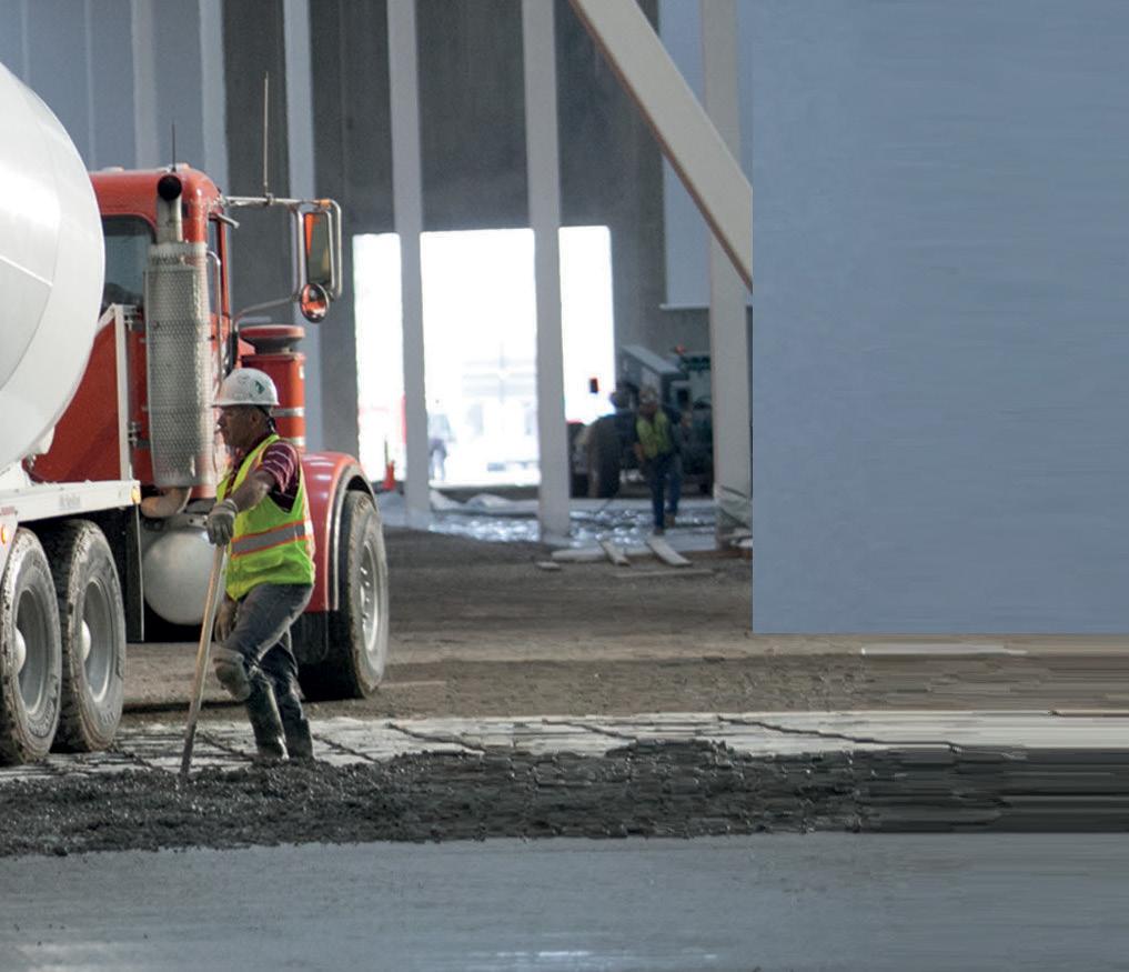
■

JANUARY 2023 43
by CTS Cement Manufacturing Corp. CTScement.com 800-929-3030 Eliminate Negative volume change Control joints Curling Maximize extended joint spacing Improve structural performance Maintain dimensional stability Lower permeability Maximize long-term durability Enhance strength and abrasion resistance ADVANTAGES MEETS STRINGENT SUSTAINABLE DESIGN CRITERIA. SHRINKAGE-COMPENSATING CONCRETE & GROUT SOLUTIONS ADVERTISEMENT–For Advertiser Information, visit STRUCTUREmag.org
NCSEA News NCSEA
National Council of Structural Engineers Associations
Highlights from the 2022 Structural Engineering Summit

The best and brightest gathered in November for the 2022 Structural Engineering Summit in Chicago


Attendees gathered to celebrate the structural engineering profession and our passion for the industry with an 80s-themed cocktail reception. Jake Elwood even made an appearance!
World-renowned architect and keynote speaker Adrian Smith of Smith+Gill Architecture shared his experiences on how he sees the built world and design professionals’ roles evolving.
STRUCTURE magazine 44
The Summit kicked off with several pre-Summit events, including a VIP tour of the Atlas Tube Mill and a Chicago Riverboat Cruise: SE Style, narrated by local structural engineers from SEAOI.
This year’s attendees had the opportunity to earn more than 14 hours of continuing education hours. These expert-led sessions ranged across several industry topics, including adapting the uniform force method, AI in structural design, and hybrid technology for steel frames and wood floors.
On day three, our keynote speaker, award-winning coach, and Ph.D. sports psychologist, Dr. Ivan Joseph, started our morning with a reminder that belief in yourself is the foundation for thriving, achieving your dreams, and unlocking your potential.
News from the National Council of Structural Engineers Associations


This year e Structure of the Year Award was introduced at the 2022 Structural Engineering Summit Awards Celebration. This new award was created to honor the most innovative and creative project, regardless of category or budget. This year’s winner was the Climate Change Arena – Seattle, WA, submitted by Thornton Tomasetti. An independent group of past presidents determined this award. To view all our award winners, visit www.ncsea.com/awards.
New this year was the first-ever Women in the Built World Panel and Networking Luncheon. Panelists described their career path, focusing on the key decisions and resulting consequences that led them to their current positions as prominent leaders in the AEC community. Following the panel, attendees gathered and celebrated women’s contributions and leadership in the built world.

Next year’s Structural Engineering Summit will be held November 7-10 at the Disneyland Hotel in Anaheim, CA. Information on attending and exhibiting will be available soon at www.ncseasummit.com

JANUARY 2023 45
on social media for the latest news & events!
award 1.0-1.5 hours
Diamond
continuing education after completing a quiz.
for the latest news on upcoming webinars and other
events.
Webinars Purchase an NCSEA webinar subscription and get access to all the educational content you’ll ever need! Subscribers receive access to a full year’s worth of live NCSEA education webinars (25+) and a recorded library of past webinars (170+) – all developed by leading experts, available whenever, wherever you need them! January 24, 2023 Work Smarter, Not Harder – Getting the Most out of Frequently Used So ware Applications February 9, 2023 Repair, Defer, or No Action: Leveraging Structure Movement Monitoring for E cient Capital Planning and Decision Making
follow @NCSEA
Courses
of
Review-approved
Visit www.ncsea.com/education
virtual
NCSEA
Learning / Networking
SEI Standards Series
February 9 and March 9
Join for a live session, dialogue between industry leaders and experts, a detailed technical presentation, extensive Q&A, and earn PDHs.
ASCE 7 & e Building Codes (Part I &II)

What Every Young Architect & Structural Engineer Needs to Know Join SEI host Cherylyn Henry, P.E., F.SEI, M.ASCE, ZAPATA Group, Inc. for a discussion with guests John Paquin, AIA, LEED BD&C, ZAPATA Group, Inc. and Gus Sirakis, P.E., NYC Department of Buildings
Focuses on ASCE 7 – which loads are included, how the loads work together and how ASCE 7 provisions are adopted into IBC and IRC codes. is program also answers the questions – what do young design professionals have to know about ASCE 7, the IBC and IRC, and where do they find the right resources?
Part I: Overview, presentation, and Q&A with industry experts
Part II: Project discussions in breakout rooms with industry experts
Learn about more sessions and register at https://collaborate.asce.org/integratedstructures/sei-standards
NEW Online ASCE Techsession
Join us for Evolutionary Optimization for Hybrid System of Post-Tensioned Cross-Laminated Timber and Light-Frame Wood Shear Walls in Mid-Rise Buildings, January 26, 1:00 pm ET, by the SEI Design of Wood Structures Committee.
• Understand the fundamental concepts of an optimization problem
• Identify design variables, constraints, and objectives to establish an optimization problem
• Understand evolutionary algorithm and how to integrate this method into the optimization process
• Live Q/A with speakers
Learn more and register at https://mylearning.asce.org/diweb/catalog/item?id=11025191.
ASCE 7 Hazard Tool Webinar
January 25, Noon ET

Includes purpose and use of the ASCE 7 Hazard Tool with updated ASCE 7-22 data and an additional overview that ties in seismic and flood hazards. e ASCE 7 Hazard Tool web-based application is easy to navigate and provides a quick way to look up eight environmental hazards for a specific location, including wind, tornado, rain, flood, snow, ice, seismic, and tsunami. Generate a summary and PDF report of the data that can be used in engineering proposals. e Hazard Tool is free to the public.
Register at https://mylearning.asce.org/diweb/catalog/item?id=11025178.
STRUCTURE magazine 46 Follow SEI on Social Media:
SEI Update
Wishing you and yours all the best in 2023!
Students/Young Professionals
More SEI Chapters Bridge the Gap

The SEI Bridge the Gap program provided small grant funding from the SEI Futures Fund in November for these local SEI Chapters to run programs promoting student and professional member interaction to attract and retain students as life-long, active SEI members.
The SEI Graduate Student Chapter at the University of Cincinnati held a networking dinner at a local brewery for UC students to connect with local professional engineers. David Odeh, P.E., S.E., SECB, F.SEI, F.ASCE, sparked engaging conversations by presenting on Trends in Structural

use of current digital technologies in design projects, the trends of advancing technology such as machine learning and AI, and ongoing work at SEI that will affect current and future professionals.
The SEI Lehigh Valley Chapter hosted a dinner, with panel discussion and networking at Lehigh University, to introduce engineering students from Lehigh, Lafayette College, and Kings College to professionals in practice. The students were very engaged and stayed late, asking questions of the early career panelists who shared tips on navigating the transition to their first jobs and the benefits of ASCE/SEI membership in building a vital network for friendship, mentorship, job opportunities, etc.
Impact the future of structural engineering and programs like this with a gift to the SEI Futures Fund www.asce.org/SEIFuturesFund
Engage undergraduate students in structural engineering

www.asce.org/SEIMembership
ASCE is the world leader in civil engineering knowledge. With more than 200,000 articles, ASCE Library attracts over a million visitors per month.
Consider sharing your research in ASCE Journals. See our open calls for papers at https://ascelibrary.org/page/callforpapers
News of the Structural Engineering Institute of ASCE JANUARY 2023 47
Membership SEI Standards Supplements and Errata including ASCE 7. See www.asce.org/SEI. To submit errata, contact sei@asce.org. Errata Call for Members for 2028 Standard Editions • ASCE 24 Flood Resistant Design and Construction • ASCE 49 Wind Tunnel Testing • ASCE 72 Design of Steel Lighting System Support Pole Structures Learn more and apply at www.asce.org/SEICommittees until January 15
Engineering covering the
Invite them to apply for an academic scholarship –
at a
conference or competition –
•
asce.org/career-growth/awards-and-honors/scholarships • Volunteer
student
asce.org/communities/student-members/conferences
member benefits for free through the
• Students enjoy ASCE/SEI
first year after graduation –
Share Your Expertise PUBLISH IN ASCE JOURNALS LIBRARY
CASE in Point

Coalitions Winter Meeting – More coming soon
The 2023 CASE Winter Member Meeting is scheduled for late Winter 2023. The Winter Meeting is open to all CASE members and is a great opportunity to network with your peers and engage in meaningful dialog about the state of the industry.
Directly following the Coalitions Winter Meeting is the Small Firm Coalition (SFC) Workshop, Small Firms and Human Resources – Developing the Workforce for the Future. This workshop is designed to address the HR Challenges of the small firm as we design the future workforce.
Your people are the key to your organization’s success. You need core elements and proactive steps to develop your leaders for tomorrow. Piece it all together in this 2-day, 8-hour interactive education session. Learn how to create dynamic, collaborative environments and, most importantly, ways to create a culture that fits your business model and attracts and retains the talent that aligns with your firm’s vision for the future. More information and registration is coming soon. Keep an eye on our website: www.acec.org/calendar-listing-acec Now more than ever, we need to support the upcoming generation of our workforce. Give to the CASE Scholarship today!
STRUCTURE magazine 48
EVENTS
News of the Coalition of American Structural Engineers
Tools to Help Your Business Grow
If you are a CASE member, this tool and all publications are free. NCSEA and SEI members receive a discount on publications. Use discount code – NCSEASEI2022 when you check out.
• Beyond the Code: Grade-Level Floors over Expansive Soils
CASE recognizes that the International Building Code or other governing codes do not address all aspects of structural engineering and design. Often, the most common issues where the owners, contractor, or design team are not aligned deal with what is not clearly addressed by the various codes or design guidelines. This is the first in a series of Beyond the Code white papers that collate design considerations that need to be discussed with the owners at the beginning of a project to establish a clear Basis-ofDesign for the project. By proactively bringing up the design consideration in front of the owners, the Structural Engineer can set realistic expectations and discuss the cost impact of alternative designs. This first white paper in the Beyond the Code series discusses the pros and cons of two structural design options for the grade-level floor in expansive soil regions. Keep an eye out for future installments in the series!

• What’s Shaking? A new publication from CASE about Seismic Design
• CASE Guideline 962- J – Business Practice Guidelines of Seismic Design for the Structural Engineer.
The purpose of this document is to provide insights into structural engineering services in regions where there is a seismic hazard. This document shares key design considerations as well as business practice considerations. Numerous resources are available that provide a much more exhaustive and advanced technical presentation of important considerations when designing for earthquakes. Someone new to designing for earthquakes should consider taking a course in structural dynamics and seismic engineering, whether from a university or some other provider such as ASCE or NCSEA. You can purchase these and other Risk Management Tools at www.acec.org/bookstore
You can also browse all of the CASE publications at www.acec.org/coalitions/coalition-publications. Is there something missing relevant to your business practice? CASE is committed to publishing the right tools for you. Have an idea? We’d love to hear from you!
About CASE Committees…
Do you know someone in your firm looking to expand and strengthen their business skillset, gain experience serving on a committee, sharpen their leadership skills, and travel to interesting places? Then, please consider applying for a position on the committee. Committee member commitments include a monthly virtual meeting, working on relevant documents a few hours a month, and traveling to the winter and summer Coalition meetings!

To apply, your firm should:
• Be a current member of ACEC

• Be a member of the Coalition of American Structural Engineers (CASE), or be willing to join the Coalition
• Be able to attend the groups’ regular face-toface meetings each year: August, February (hotel, travel partially reimbursable)
• Be available to engage with the committees via email and video/conference call
• Have some specific experience and/or expertise to contribute to the group
JANUARY 2023 49
Business Planning for 2023
By Kacey Clagett and Tiany Galaskas
Engineering companies nationwide face labor constraints for experienced professionals to deliver work, continued supply chain disruptions, and construction labor and materials shortages caused by the Covid-19 pandemic. Moreover, economic conditions grow more challenging with elevated inflation, higher interest rates, and concerns that the U.S. economy is on the brink of a recession. Yet the top 10 publicly traded A/E/C companies are experiencing increased revenue through organic growth and expect more growth in 2023, although some do maintain their caution for the year ahead. Their strategies provide insights for companies of all sizes.
The Covid-19 pandemic placed commercial real estate at the epicenter of the crisis, disrupting property cash flows. This had immediate effects across all property types, particularly for office buildings and convention centers. The office market is forecasted to stay relatively flat. Although convention center use is still below pre-Covid levels, the volume has picked up in 2022, and cancellation rates are falling.
While the commercial market has not rebounded to pre-Covid levels, the technology sector is poised for continued growth. Economists expect their percentage of total GDP will double from 5 to 10 percent by 2030. This will demand new data centers, industrial manufacturing, and advanced technology manufacturing spaces. The industrial market continues to see strong long-term fundamentals across the U.S., as does the multi-family market. The Florida and Southwest markets are generally expected to outperform the nation. Retail e-commerce is predicted to increase by more than 50% towards 2023, requiring distribution centers and efficient transportation. Health and life sciences, automotive & technology, public transportation, and aviation will also thrive.
The ESG (Environment/Social Responsibility and Governance) policies of capital sources and large corporations increasingly drive opportunities for the A|E|C industry, such as in energy efficiency, renewable electricity, direct emissions abatement, carbon removal, and clean energy. They also open new markets to disadvantaged businesses. The global environmental remediation market is expected to experience a 7.5% compound annual growth rate between 2020 and 2027, an uptick to $100B. The green technology and sustainability market should rise by 27%, up to
$29B between 2019 and 2024. The renewable energy market is expected to require $125 trillion in investment over the next 30 years, including electrical grids. Civil infrastructure renewal will increase. Remediation of PFAS (per- and polyfluoroalkyl substances) in water supplies is propelling state and federal regulations and funding. The drinking water remediation technology spend is forecasted at $6.15B for this decade. Other construction growth areas are nuclear energy and waste management. Protecting coastal communities (the U.S. alone will require $400B in the next twenty years) will become an established market. Property damage appraisal, structural and civil forensics, and environmental consulting will also be needed to recover from the increasingly pronounced effects of climate change and extreme weather events.
Federally funded programs provide government, nonprofit, and private sector opportunities. The $114B Infrastructure Investment and Jobs Act passed in 2021; notices of funding opportunities are accelerating. The expected funding will most meaningfully benefit U.S. markets from fiscal 2023 through the next 5 to 10 years. The July 2022 Chips and Science Act provides $52B to support semiconductor chip manufacturing, including $39 billion for plant construction. The August 2022 Inflation Reduction Act brings another $50B, including $5B for programs that accelerate the construction industry’s shift toward green building materials and $4B to improve resiliency in affordable housing, such as funds for low-carbon materials. It allows FEMA’s Building Materials program to offer financial assistance for low-carbon materials and net-zero energy projects.
Recommendations
Wei Li, the Global Chief Investment Strategist for BlackRock, has stated that the themes for planning are “Back to a volatile future Number one, bracing for volatility. Number
two, living with inflation, and number three, positioning for net zero.” Consider these recommendations as you do your business planning for the year:
• Keep adequate reserves.
• Maintain emphasis on your best clients. For example, they may be responding to economic conditions with their workforce adaptations, or they could be planning to take advantage of climate and resilience loans and tax credits.
• Focus on opportunities to add digital analytics or shift into climate-related industries.
• Diversify your portfolio and identify strategic partners for key markets or to enter new markets.

• Create nimble teams to manage smaller capital construction programs.
• Continue to position for alternative project deliveries, like design-build, and services that have some vitality should a recession take hold, such as studies, or work in less volatile market sectors, like infrastructure.
• Invest in innovation.
• Develop your staff’s skills in client management and service. We are living in an unpredictable world, and anything can arise. We recommend that companies perform a risk analysis and evaluate conditions for success as part of their planning process. At the same time, be prepared to pivot if the landscape changes.
■
Kacey Clagett (kacey.clagett@ appleseedstrategy.com) and Tiany Galaskas (tiany.galaskas@appleseedstrategy.com) are Principals of Appleseed Strategy.
STRUCTURE magazine 50 business PRACTICES JANUARY 2023
IT TAKES A BIG STEP TO LEAVE A SMALLER FOOTPRINT.
ROADMAP

TO CARBON NEUTRALITY. BE PART OF THIS IMPORTANT MISSION.

In October 2021, PCA released a groundbreaking initiative called the Roadmap to Carbon Neutrality.



The concept is simple: to mobilize our industry to dramatically reduce CO2 emissions and to achieve carbon neutrality across the entire cement and concrete value chain.
It’s an audacious goal, and we’ll need to work together across the built environment from design, to manufacturing, delivery, and construction.
Learn how you can be an important part of shaping a more sustainable world.


Contact Nick Ferrari at nferrari@cement.org
shapedbyconcrete.com
CEMENT.ORG


csiamerica.com

STRUCTURAL AND EARTHQUAKE ENGINEERING SOFTWARE
Computers and Structures, Inc. is an ISO 9001-certified company.


 John Dal Pino, Chair, STRUCTURE Editorial Board


 By Eka Linwood, P.E.


 By
By


