SECURE. TWIST. MARVEL.
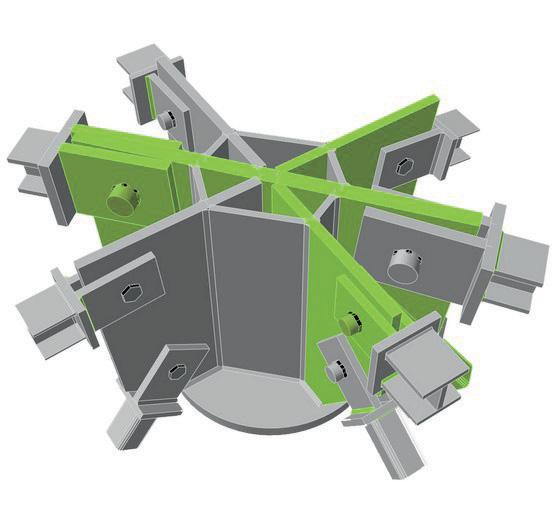
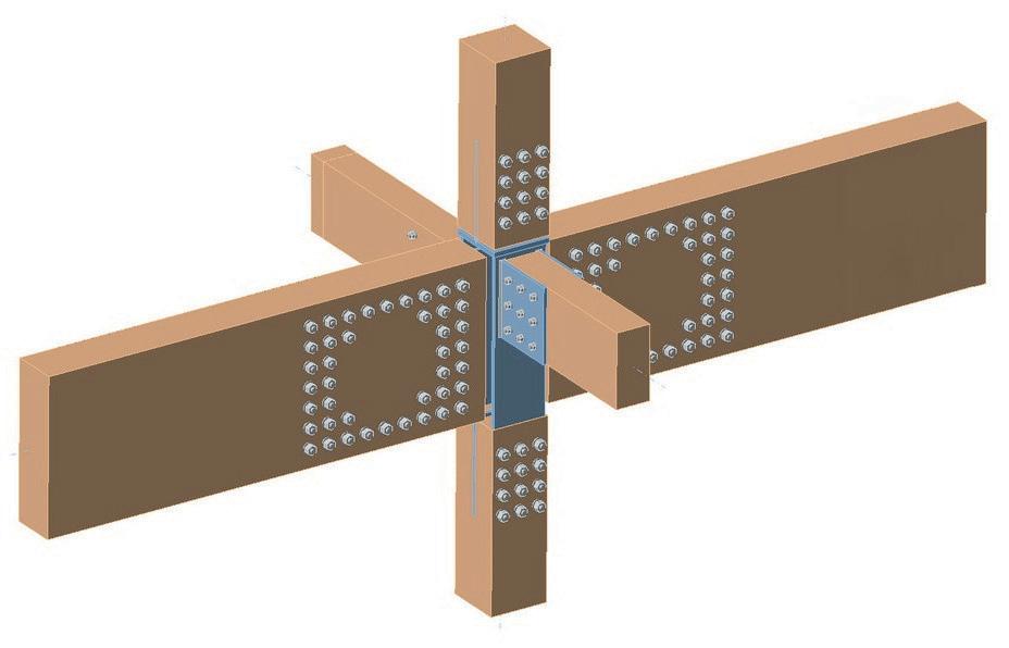
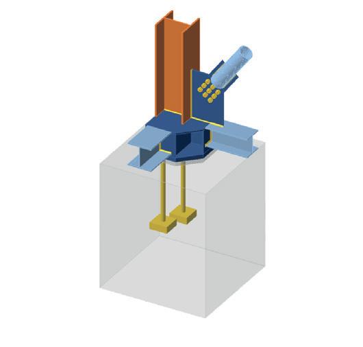
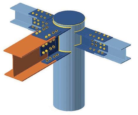
Shuriken™ makes bolting HSS, SpeedCore and more possible, so you can affordably incorporate them into your buildings without hesitation. Go ahead — design away!
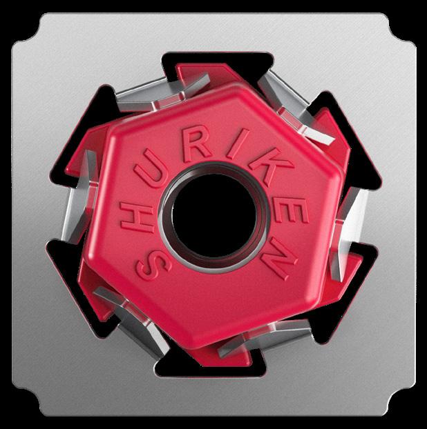


Shuriken™ makes bolting HSS, SpeedCore and more possible, so you can affordably incorporate them into your buildings without hesitation. Go ahead — design away!


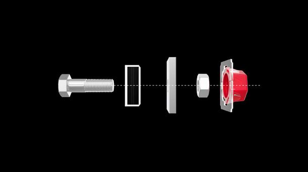
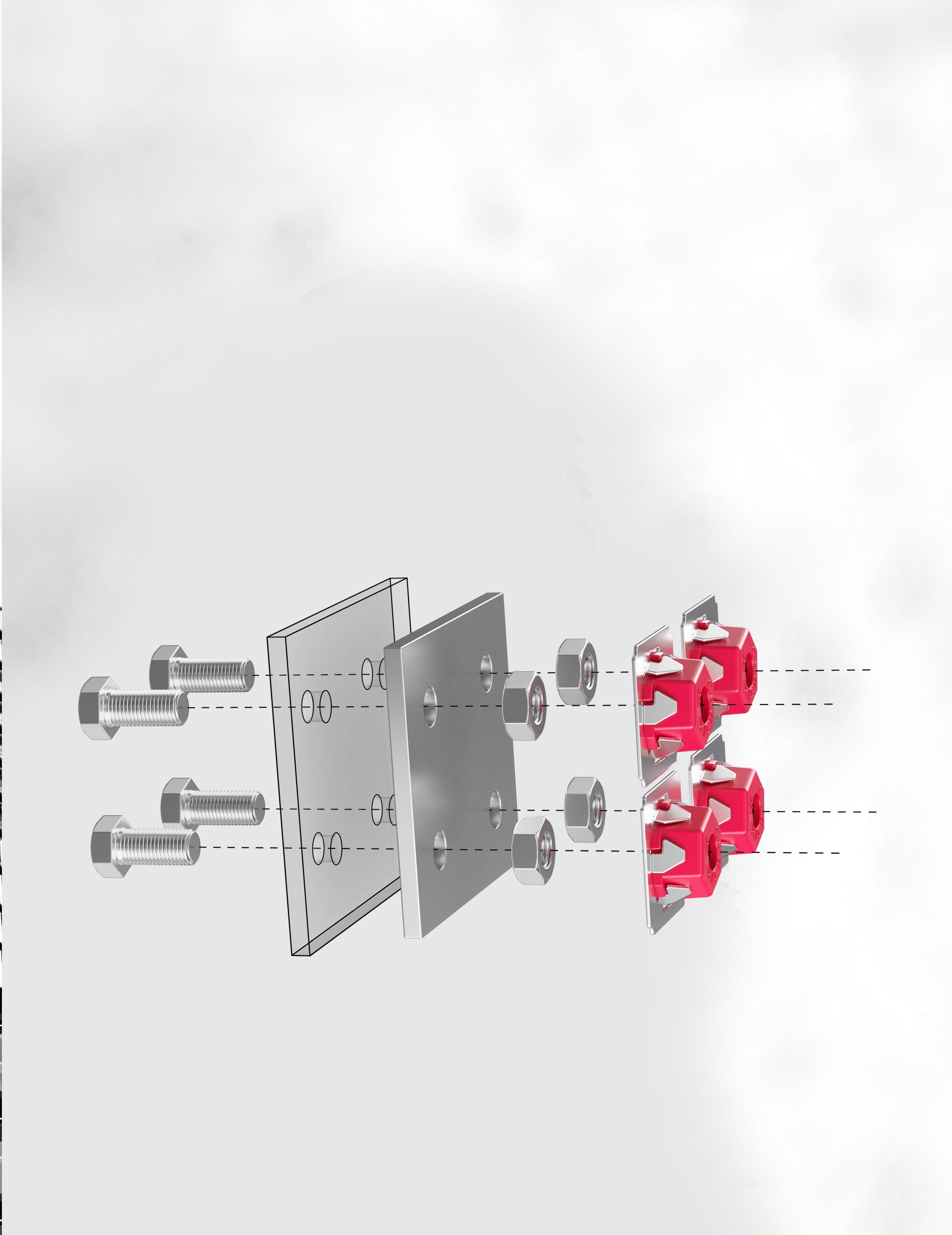
Shuriken™ is a built-in wrench that lets you field bolt connections that used to require welding — like HSS columns, trusses and beams; SpeedCore; connections in tight spaces; retrofits; and more. Using Shuriken to bolt HSS results in fewer field welds, easier installation, faster visual inspections and lower costs, which means you get all the benefits of HSS without any drawbacks.
Bolt HSS in three simple steps. Watch how it works.
Elegant. Deliberate. Consistent.
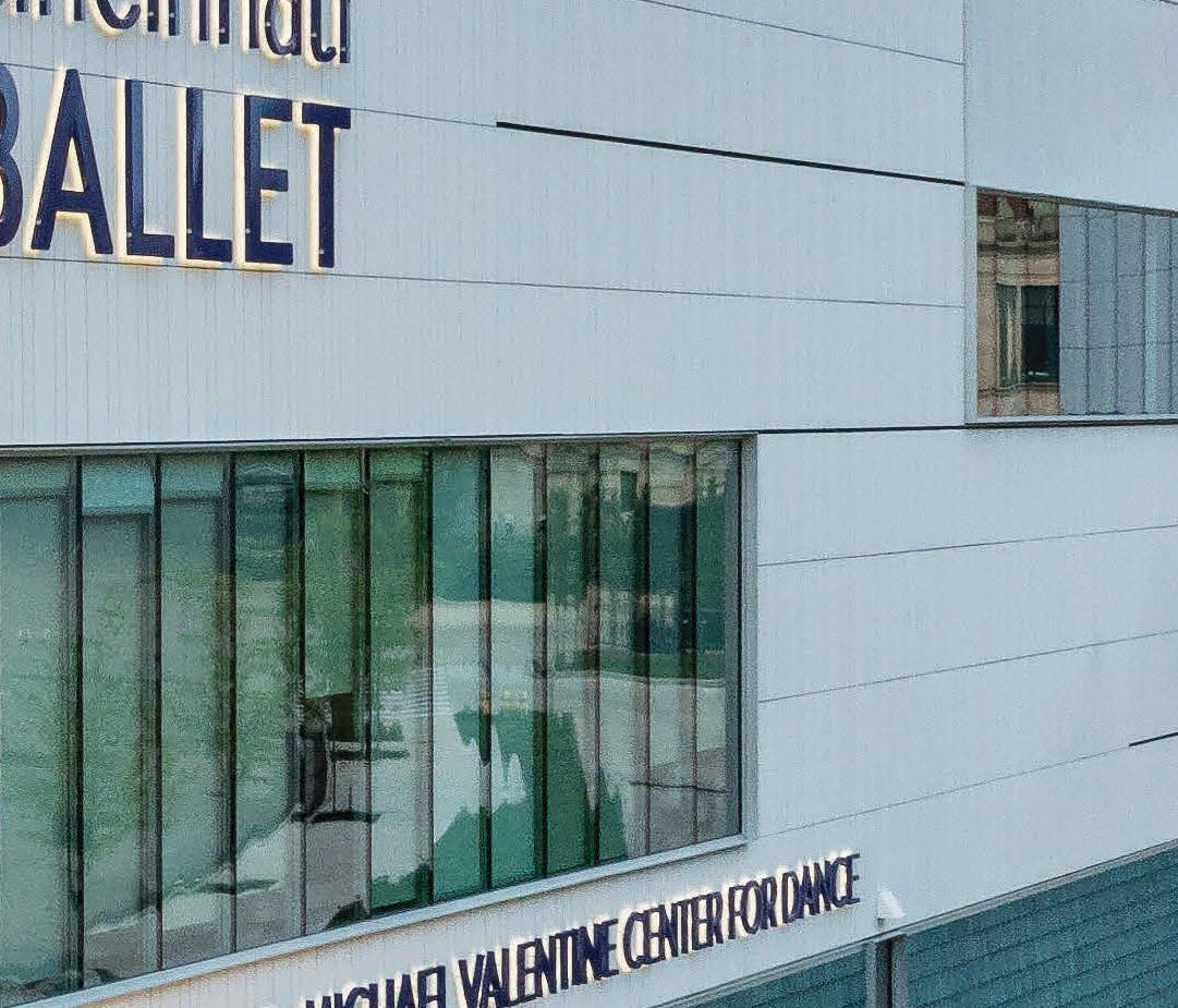
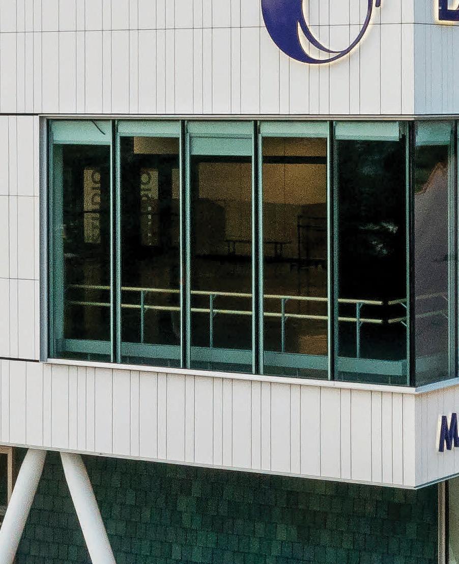
Cincinnati Ballet Margaret and Michael Valentine Center for Dance more than doubles the Ballet’s previous space. Cast Connex ® Architectural Tapers™ (ART) finish the end of HSS columns that grace the building’s entrances. Cast Connex ARTs allow the stylistic columns to successfully embody the elegance of the dance positions that inspired them. The result: An instantly recognizable statement made with refined simplicity.
CAST CONNEX ® Architectural Taper ™ (ART)

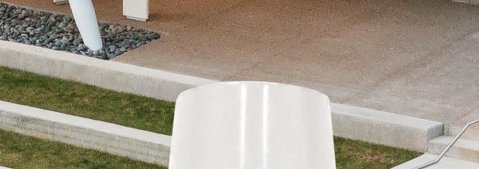
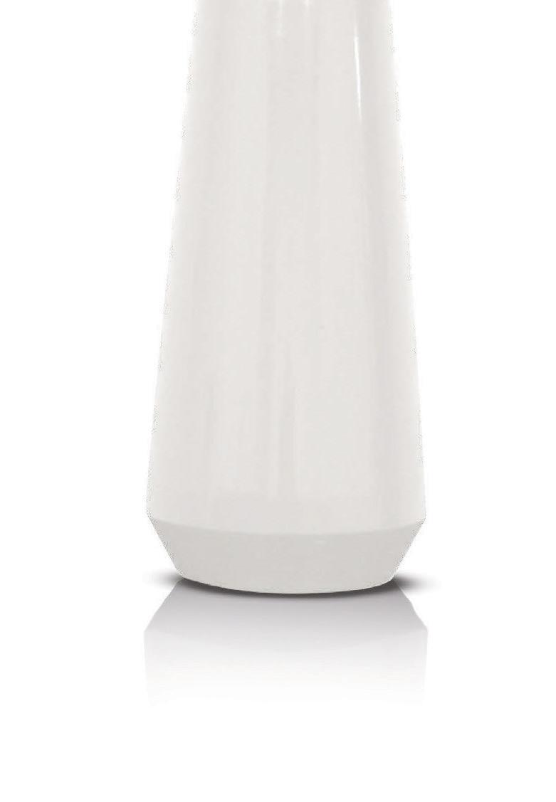

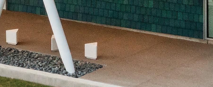
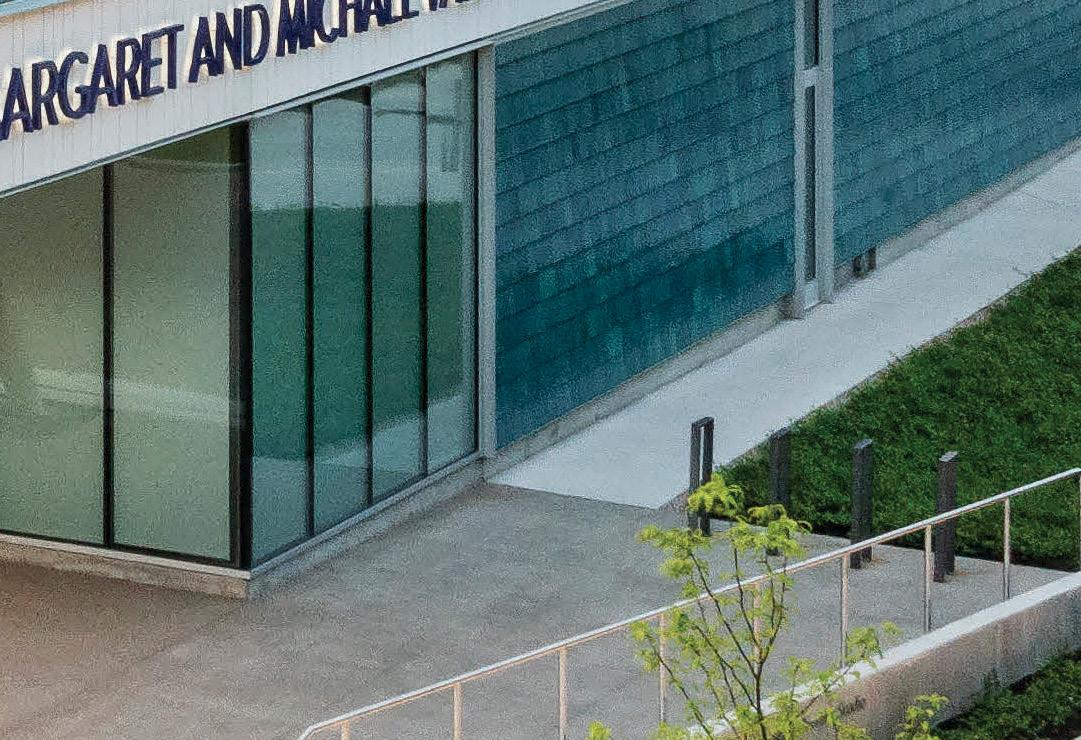
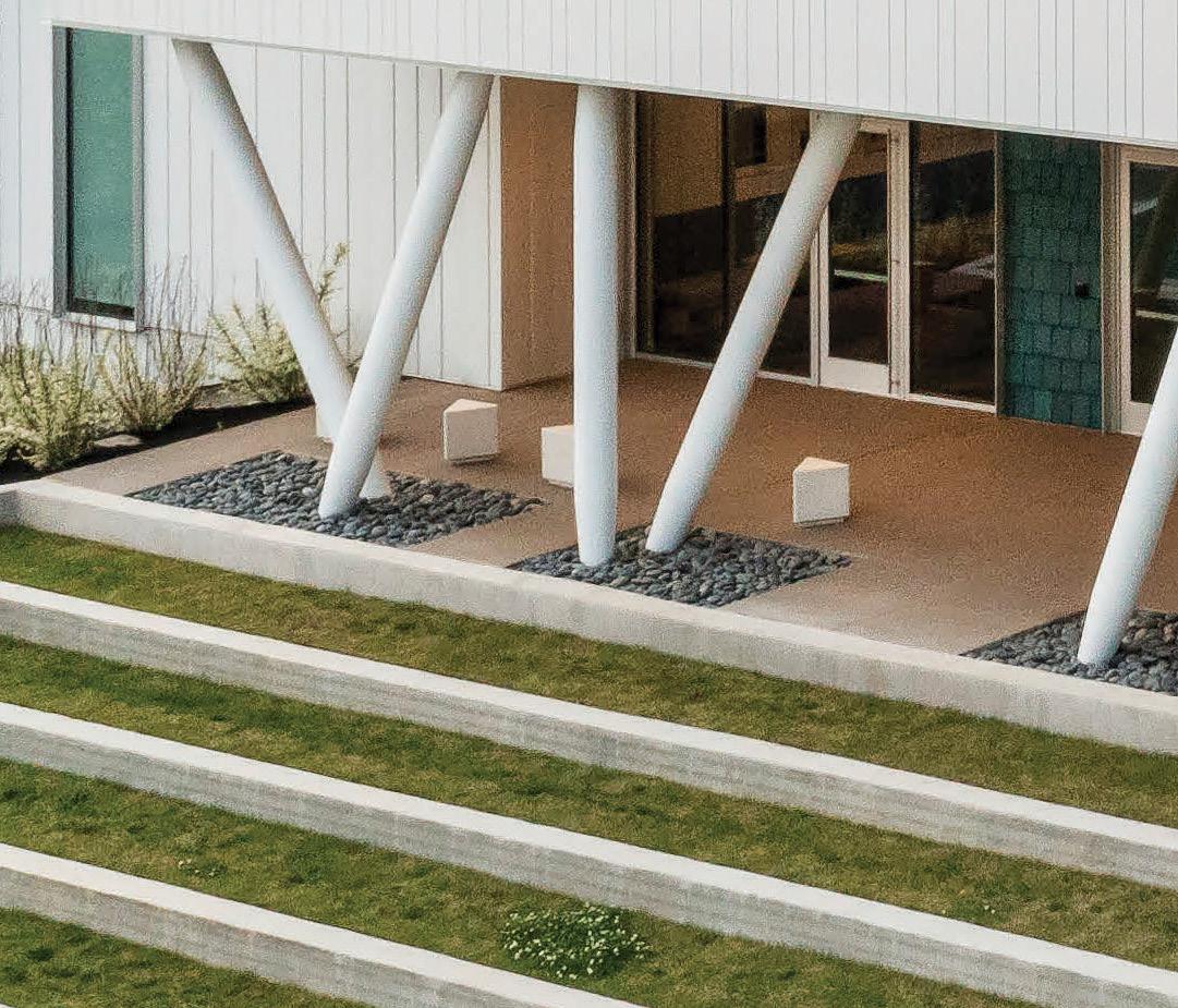


Consistent Fabrication of hollow conical steel tapers is difficult, specifying Architectural Tapers will ensure availability, cost effectiveness, and consistency in appearance and quality.


American Concrete Institute
Atlas Tube 1 | 2
Cast Connex
Clark Dietrich Building Systems Computers & Structures, Inc Concrete Reinforcing Steel Institute Degenkolb Engineers Dewalt DuraFuse Frames
ENERCALC
ICC IDEA StatiCa
Integrated Engineering Software KPFF

Errata
MAPEI Corp
Martin/Martin
New Millennium Building Systems Nucor Tubular Products
Nucor Vulcraft Group - Redicor PCS-Structural RISA Technologies Schock North America
Simpson Strong-Tie 1 | 2 Structural Engineering Institute of ASCE Trimble Wire Reinforcement Institute Woodworks
The authors of Highlight on Sustainability: Boston University Center for Computing & Data Sciences (June 2022) brought to STRUCTURE’s attention that their portland cement replace ment rate of 63% was inaccurate. The line should have read: Through early engagement and subsequent dialogue throughout the procurement and installation process, the project employed concrete with portland cement replacement rates of up to 70%, the highest ever used in Boston for this type of application. The online version has been corrected.
It also was brought to STRUCTURE’s attention that in the October 2022 article, Inside the Box, Brininstool + Lynch was the Associate Architect for the project. The information has been added to the online version of the article.
Director for Sales, Marketing & Business Development
Monica Shripka Tel: 773-974-6561 monica.shripka@STRUCTUREmag.org
Executive Editor Alfred Spada aspada@ncsea.com
Publisher Christine M. Sloat, P.E. csloat@STRUCTUREmag.org
Associate Publisher Nikki Alger nalger@STRUCTUREmag.org
Creative Director Tara Smith graphics@STRUCTUREmag.org
Chair John A. Dal Pino, S.E. FTF Engineering, Inc., San Francisco, CA chair@STRUCTUREmag.org
Jeremy L. Achter, S.E., LEED AP ARW Engineers, Ogden, UT
Erin Conaway, P.E. AISC, Littleton, CO
Linda M. Kaplan, P.E. Pennoni, Pittsburgh, PA
Charles “Chuck” F. King, P.E. Urban Engineers of New York, New York, NY
Nicholas Lang, P.E. Masonry Industry Representative
Jessica Mandrick, P.E., S.E., LEED AP Gilsanz Murray Steficek, LLP, New York, NY
Jason McCool, P.E. Robbins Engineering Consultants, Little Rock, AR Brian W. Miller Davis, CA
Evans Mountzouris, P.E. Retired, Milford, CT
John “Buddy” Showalter, P.E. International Code Council, Washington, DC Eytan Solomon, P.E., LEED AP Silman, New York, NY
Jeannette M. Torrents, P.E., S.E., LEED AP JVA, Inc., Boulder, CO
STRUCTURE ® magazine (ISSN 1536 4283) is published monthly by The National Council of Structural Engineers Associations (a nonprofit Association), 20 N. Wacker Drive, Suite 750, Chicago, IL 60606 312.649.4600. Periodical postage paid at Chicago, Il, and at additional mailing offices. STRUCTURE magazine, Volume 29, Number 11, © 2022 by The National Council of Structural Engineers Associations, all rights reserved. Subscription services, back issues and subscription information tel: 312-649-4600, or write to STRUCTURE magazine Circulation, 20 N. Wacker Drive, Suite 750, Chicago, IL 60606.The publication is distributed to members of The National Council of Structural Engineers Associations through a resolution to its bylaws, and to members of CASE and SEI paid by each organization as nominal price subscription for its members as a benefit of their membership. Yearly Subscription in USA $75; $40 For Students; Canada $90; $60 for Canadian Students; Foreign $135, $90 for foreign students. Editorial Office: Send editorial mail to: STRUCTURE magazine, Attn: Editorial, 20 N. Wacker Drive, Suite 750, Chicago, IL 60606. POSTMASTER: Send Address changes to STRUCTURE magazine, 20 N. Wacker Drive, Suite 750, Chicago, IL 60606.
STRUCTURE is a registered trademark of the National Council of Structural Engineers Associations (NCSEA). Articles may not be reproduced in whole or in part without the written permission of the publisher.




Located right here in the U.S., the world’s largest continuous ERW mill rolls Jumbo HSS — the biggest domestic HSS available anywhere. With the high quality and fast delivery times you expect from Atlas Tube, it’s never been easier to start planning big things.
QUICKLY AND EASILY FIELD BOLT JUMBO HSS. Learn how Shuriken™ makes it possible at atlastube.com/shuriken
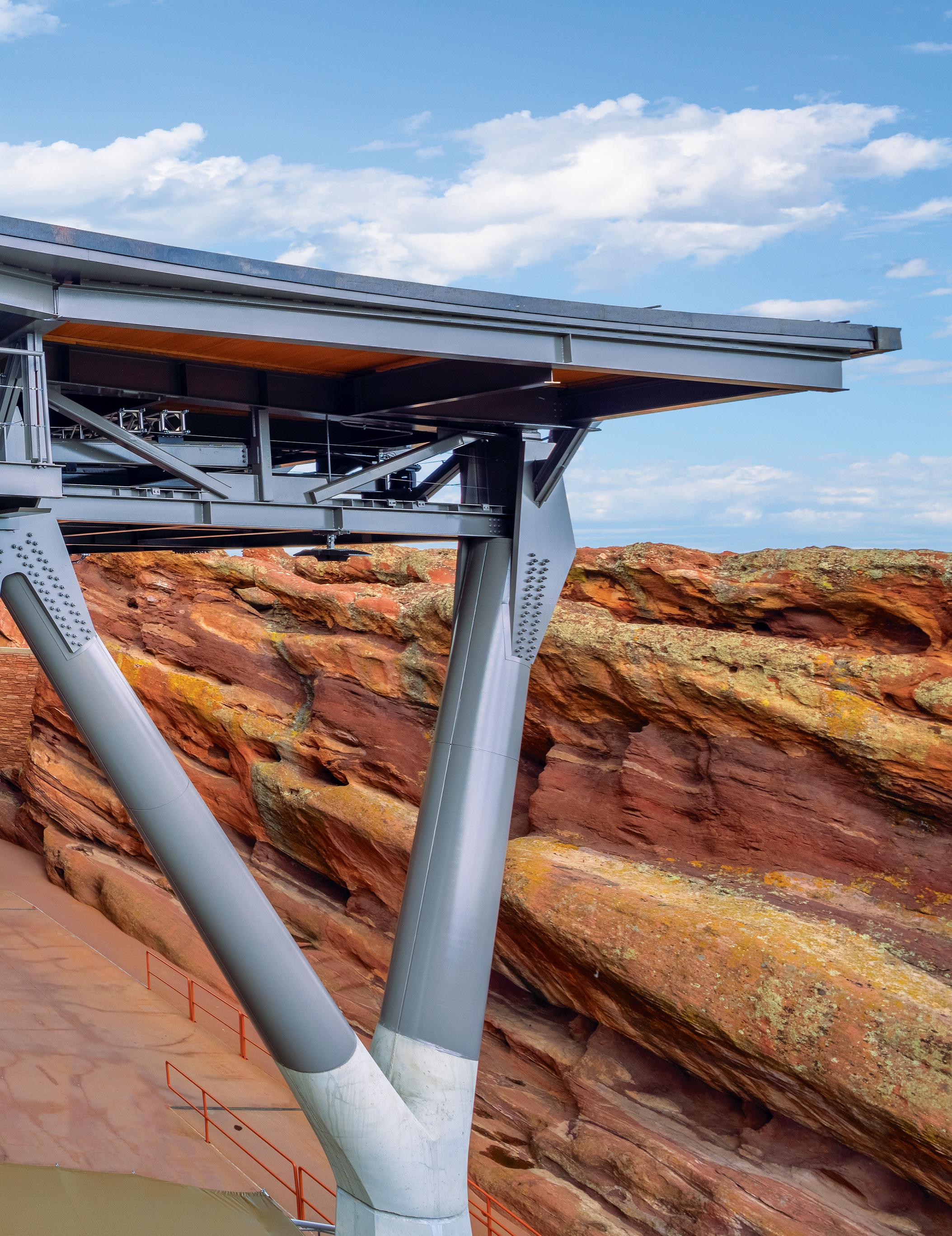
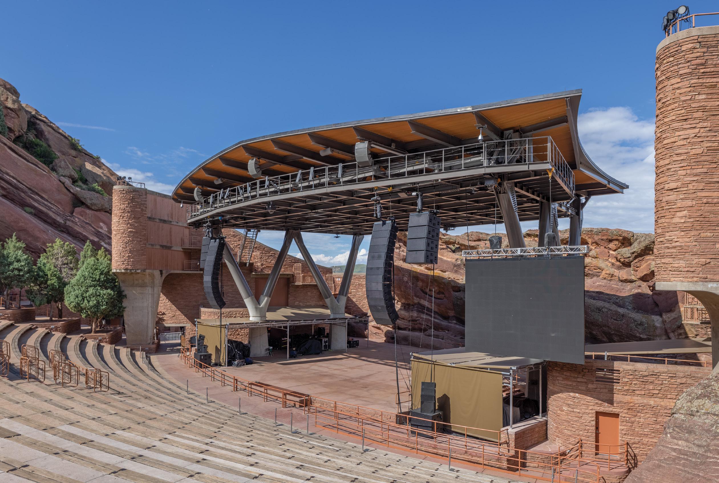
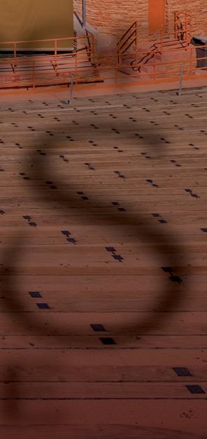
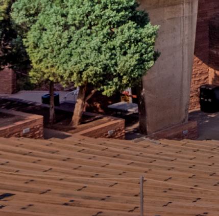
Photo by Max TouheyOver time, the steel space frame roof of the Red Rocks Amphitheater stage (circa 1989) was deemed structurally insufficient due to rigging issues and increased rigging demands. The complete removal of the existing roof structure and a replacement structure with an increased rigging capacity was required. The new roof structure can be divided into three layers: top chord framing, rigging level, and bottom chord framing.
 By Jessica Mandrick, P.E., S.E., Karl Rubenacker, P.E., S.E., and Lizhong Wang
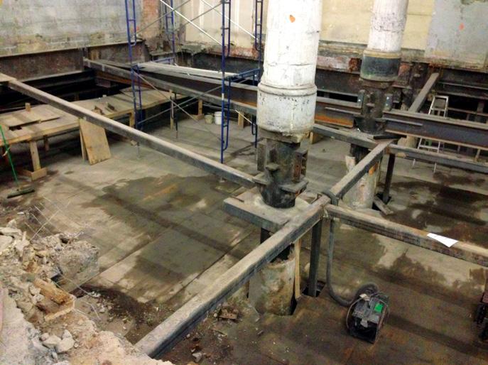
Historic cast iron column buildings require special attention during renovations. 315 Hudson Street is a ten-story cast iron column building undergoing such alteration. Renovations included lowering a portion of the ground floor structure, transferring two off-grid columns at the ground floor via transfer beams, and reinforcing columns for new rooftop loads. Complexity was challenging when bracing, supporting, and reinforcing the cast iron columns in a manner that limited tension.
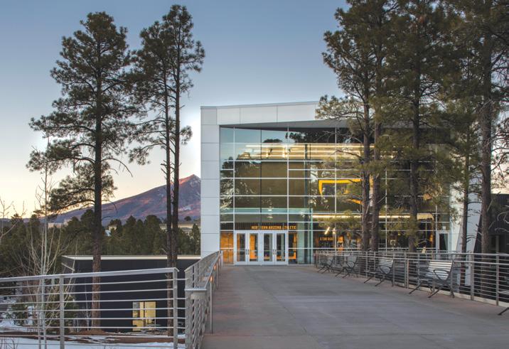
The Northern Arizona University Student-Athlete High-Performance Center building is located on a hillside. Its third-level auditorium and hall of fame are rotated to maximize views, and the pedestrian entrance is located at the third level. The auditorium was initially conceived to be framed as a truss, independent from the rest of the structure. However, a review of alternatives resulted in the auditorium being ultimately framed with conventional steel.

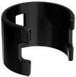
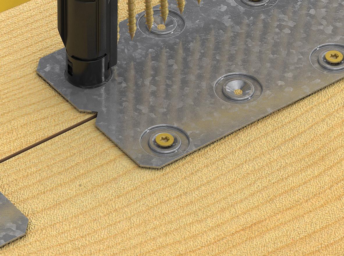
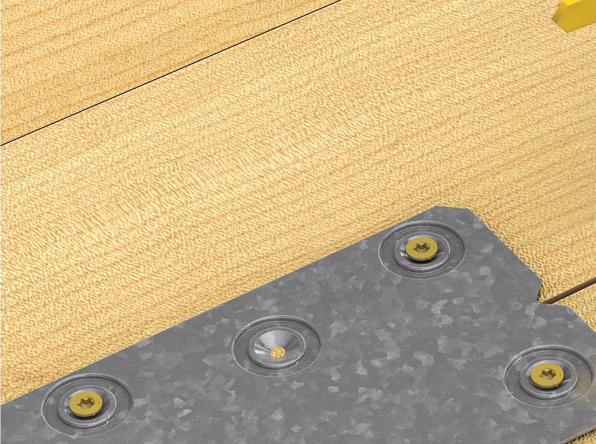
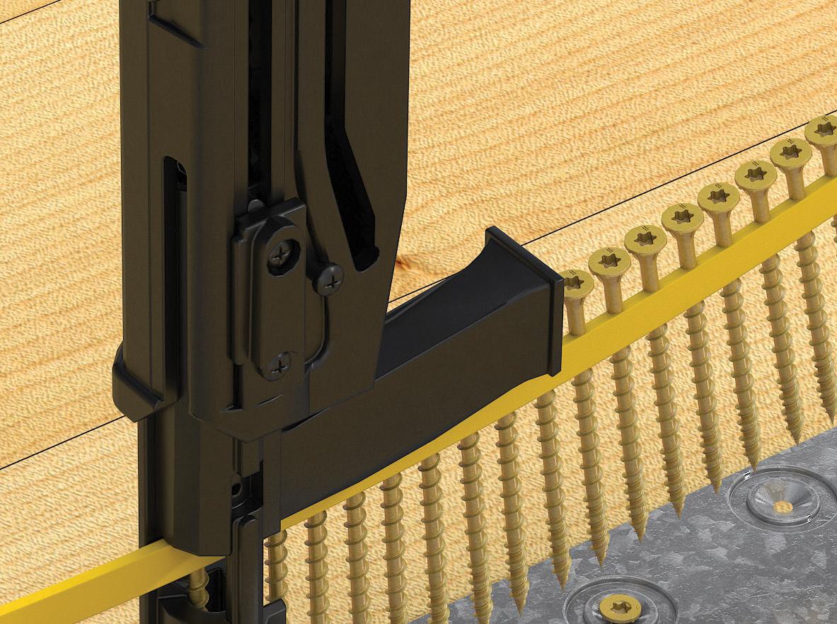
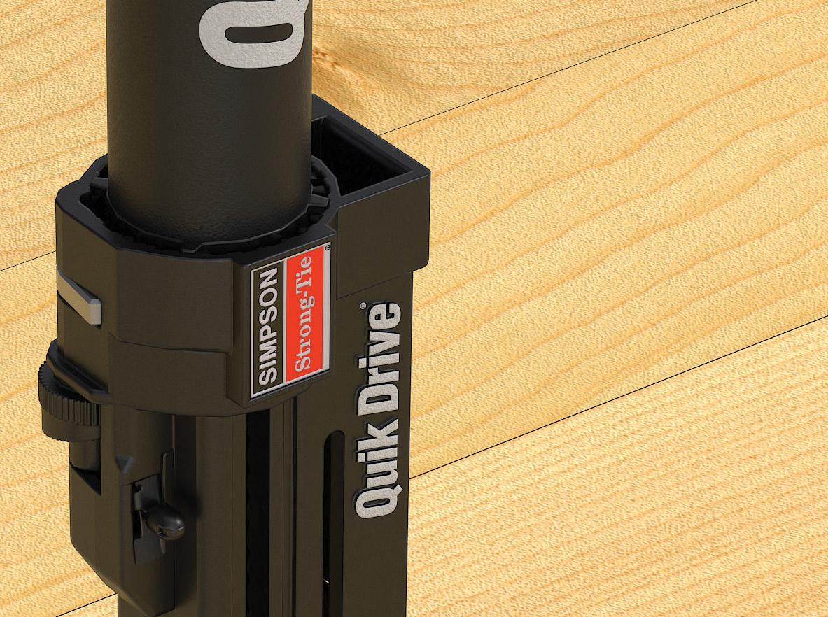
Our new LDSS spline solution for mass timber panel connections includes the LDSS light diaphragm spline strap, PRO300SG2 Quik Drive ® tool and collated Strong-Drive ® WSV screws. The steel LDSS strap attains high loads at a lower installed cost than plywood. Placed on top of CLT and other types of mass timber panels, it eliminates the need for CNC routing. The strap fastens quickly and easily with the Quik Drive tool, unique noseclip and screws. The Simpson Strong-Tie ® LDSS spline strap is tested, widely available and backed by our expert service and technical support. Switch to the LDSS spline solution for your next design. To learn more, visit go.strongtie.com/LDSS or call (800) 999-5099.



By Nathan Roy, P.E., Jamie Hamelin, P.Eng., Dave Smythe, and Alan Simon, P.E.
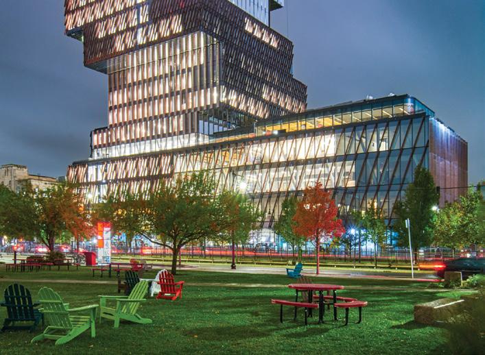
Early on, discussions with the owner, design team, structural engineering team, and the construction manager identified the means and methods of erection as critical to the success of the Boston University’s Center for Computing & Data Sciences Building. Design-Assist was utilized to identify the temporary erection procedures required to construct this building, a 19-story, 305-foot-tall tower with 25-foot cantilever volumes offsetting in a counter-clockwise arrangement every two to three stories.
Editorial
Building
Engineering for Life
Architecturally
By Bryan G. Cortnik, MS, P.E., S.E.
Publication of any article, image, or advertisement in STRUCTURE® magazine does not constitute endorsement by NCSEA, CASE, SEI, the Publisher, or the Editorial Board. Authors, contributors, and advertisers retain sole responsibility for the content of their submissions. STRUCTURE magazine is not a peer-reviewed publication. Readers are encouraged to do their due diligence through personal research on topics.




As a new engineer, I was at a site one afternoon struggling over a por tion of a project not installed per plan. The contractors’ position was that the plan asked for something that was not done. The design team’s point was that they should have qualified their bid if the contractor knew this was not possible. My role was to defend specifying that the elevator guide rails for a 2-story wood framed building with less than 10-foot story heights needed to span floor-to-floor (i.e., a guide rail support tube would not be provided). While the details were eventually worked out, the outcome of this experience is the more important story.
As the argument progressed, the owner’s representative for the project, a therapeutic equestrian center where horses could nurture children and young adults with disabilities, joined the conversation. He com mented that he understood the tension of the situation we were trying to solve, but he asked that we turn around and witness the reason for the building in the first place. As we turned, a young boy was climbing into the saddle of his horse for the day. The smile on his face was big, but the care expressed in the eyes of his aide was equally powerful. This was the day I learned structural engineers don’t design beams and columns or shear walls or elevator guide rails. Instead, we design places where life happens.
This experience shaped my view of structural engineers’ impact on communities and society. We all know teachers develop our children, doctors cure our ills and keep us healthy, truck drivers deliver every thing we need from manufacturer and farm to market, and grocery and retail team members make sure the shelves are stocked with everything we need; the list is almost limitless. But what do all of these have in common? Every school, hospital, bridge, airport, retail store, warehouse, apartment, hotel room, home, and more was real ized through the impact and contribution of a structural engineer. Without the structural engineer, the built environment and all that relies on it would not be possible. Structural engineers design the fabric of society…what greater impact is there?
Structural engineering creates the underlying support of buildings and infrastructure. As many explain, structural engineering provides the bones and muscles of a project. When coordinated with other parts of a building, these skeletons create safe structures available to the community for use in securing opportunities to live, work, play, and, hopefully, thrive. For structural engineers, it is exciting to bring new structures out of the ground. But engineers don’t just address new buildings. An incredible inventory of existing buildings could live for a longer time. Engineers are needed to help maintain, renovate, and retrofit existing buildings to ensure they remain safe and secure.
Unfortunately, natural and man-made hazards often require struc tural engineers’ involvement in the repair of damaged structures as well. Following disasters, the structural engineering profession is called upon to support search and rescue efforts, stabilize vulnerable structures, provide post-disaster safety assessments of buildings before re-occupancy, and work with owners and communities to restore buildings to full function. In these efforts, the structural engineer fulfills their greatest duty to protect and safeguard the health, safety, and welfare of the communities they serve.
Structural Engineering is a dynamic profession, constantly improving by learning from past events and developing new approaches based on
emerging technologies, systems, and materials. The ability to adapt and use creative technologies such as virtual reality to experience the building before it is built, drone mapping to capture the structure of an existing building, and advances in computer technology and analytical tools provide multiple avenues for structural engineers to support the profession. The built environment is established within building codes and standards, which provide performance criteria to ensure structures meet the occupants’ needs. These documents are not static; they are regularly updated based on input from structural engineers involved in research and code development activities. Many of these activities result from lessons learned during and after realworld and hands-on experiences with hazards and disasters and the need to respond to societal changes.


Future-proofing the built environment includes protecting cultural heritage and preserving the historic fabric of our building inventory, thereby ensuring cultural lessons are not lost in the hustle of progress. It also means taking purposeful steps in creating a sustainable response to change. Whether it is continually minimizing the carbon footprint and impact of our buildings on the climate, assessing the condition of existing buildings to ensure they remain capable of serving society, or ensuring structures have the resilience to recover from a disaster event, structural engineers impact the very fabric of who we are and how we interact.
Engineering graduates joining the profession are commonly tasked with simple assignments as they hone skills and build experience lead ing to ever-expanding responsibilities. Early efforts narrowly focused on discrete elements or systems can make it hard to see the larger outcome. As careers progress, the larger outcome can be seen as the complete structural system or, often, the complete building. However, most users of structures do not see the complexity of the engineered solution, nor do they feel the dynamic collaboration necessary to make it happen. Instead, people feel and value their experience within the built space. In serving our communities, our opportunity is to see engineering as a way to impact the experience people feel every day, not just when the wind blows or when the earth shakes. Our challenge is to embrace the engineer’s role as more than engineering for structures, but rather Engineering for Life.
■
This was the day I learned structural engineers don’t design beams and columns or shear walls or elevator guide rails. Instead, we design places where life happens.
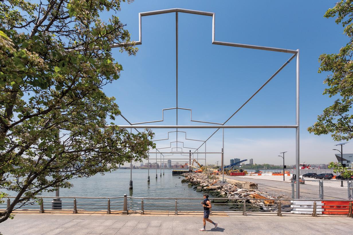
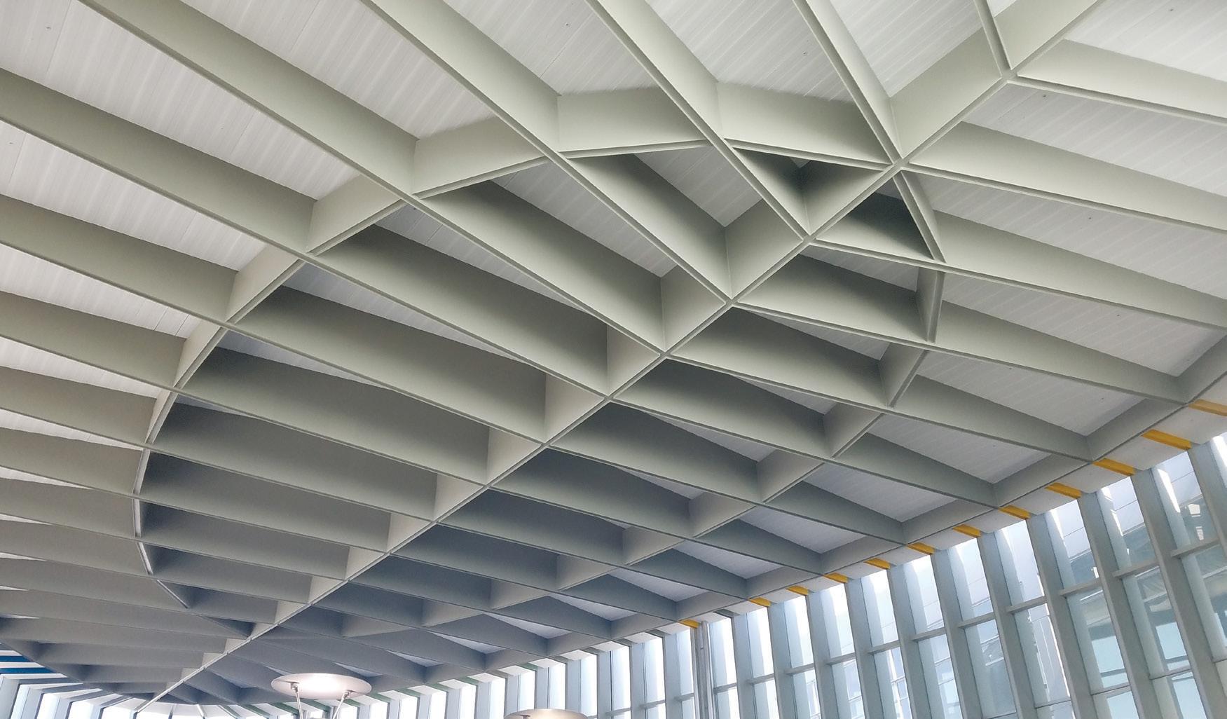
When properly executed, the decision to expose structural steel offers a powerful opportunity to express a project’s tectonics and aesthetic goals. The 2016 American Institute of Steel Construction (AISC) Code of Standard Practice for Steel Bridges and Buildings (ANSI/ AISC 303) introduced the architecturally exposed structural steel (AESS) category system, a systematic method of communicating craftsmanship quality to support goals for the final appearance of the finished structure. Prior to 2016, the lack of a categorized approach uniformly accepted by the Architecture-Engineering-Construction industry posed challenges in communication between the design and construction team, as well as with Owners. Today, when properly understood and leveraged, the Category system can support project outcomes that meet designers’ intent, are properly budgeted during the bid process, and achieve ultimate aesthetic goals for which fabri cation quality is a foundation.
Still, even as designers have become more familiar with the category approach, additional questions have arisen about achieving AESS goals successfully; additional resources have been developed in response. This article provides an overview of guidance on best practices for designers considering AESS for their projects, including an outline of recently developed resources and tips on how to address frequently asked questions.
Since 2016, new standards of care and guides by AISC and the American Galvanizers Association (AGA) have been developed to support AESS design:
• Code of Standard Practice for Steel Buildings and Bridges (AISC/ ANSI 303-22) – the new COSP provides a few modifications to the standard of care for AESS that provides more clarity for the fabrication and erection of AESS.
• Code of Standard Practice for Structural Stainless Steel Buildings (AISC 313-21) – this new standard of care introduces a category system for architecturally exposed structural stainless steel (AESSS).
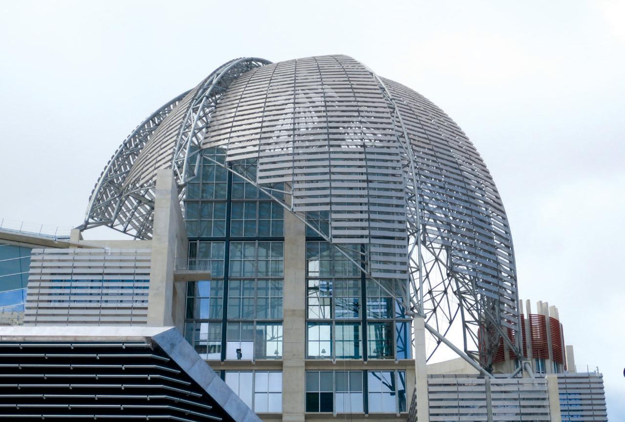
• Hot-Dip Galvanized Architecturally Exposed Structural Steel –Specifiers Guide (AGA 2021) – this new design guide helps designers achieve both low maintenance corrosion protection with the enhanced aesthetics for galvanized AESS.
In addition to industry publications, project teams are encouraged to discuss time and labor-saving best practices with structural steel and stainless steel fabricators. Architecturally Exposed Structural Steel: Specifications, Connections, Details by Terri Meyer Boake includes inspirational AESS projects from around the world, making it an excellent addition to any AESS library.
In 2021, Section 10 of the AISC Code of Standard Practice for Structural Stainless Steel defined the five categories for architecturally exposed structural stainless steel (AESSS). And similar to AESS, the AESSS categories are as follows:
AESSS 1: Basic elements.
AESSS 2: Feature elements viewed at a distance greater than 20 feet (6 m).
AESSS 3: Feature elements viewed at a distance less than 20 feet (6 m).
AESSS 4: Showcase elements with special surface and edge treatment beyond fabrication.
AESSS C: Custom elements with characteristics described in the contract documents.
While on the surface, the AESSS categories appear to mimic the AESS categories, designers should note that the fabrication, finishing, and erection requirements for AESSS vary greatly from AESS. erefore, designers first exploring AESSS are encouraged to reach out to stainless steel fabricators and review Chapter 11, Fabrication and Erection, of the updated AISC Design Guide 27 – Structural Stainless Steel
It is vital to include thorough specification language and information on the project design drawings to properly communicate the desired level of craftsmanship and scope for exposed structural steel and structural stainless steel. AESS/AESSS is under the scope of the steel fabricator, and while creating their bids, the fabricator looks to the 051210 section for AESS/AESSS requirements. Standard specification language can be found on MasterSpec or other platforms – rather than including the entirety of the boilerplate specification for all categories, consider deleting categories not relevant to the project to help avoid confusion during the bid process.
e category type and extents of AESS/AESSS should be shown on the design drawings – at a minimum on the Structural Set as these are the documents that steel fabricators look to first to define AESS/AESSS scope. erefore, be sure to clearly call out the Category and extent of said category on the drawings. Successful approaches to this may include extent lines on details with detail sheet notes; for complex projects, a shaded isometric drawing may be used to indicate AESS/ AESSS extents. is is particularly helpful at transition points between AESS/ AESSS categories and between AESS/ AESSS and standard fabrication.
For larger projects, it is suggested that the design team conducts a kickoff meeting with the winning contractors to ascertain that the AESS/AESSS scope – including category types and extents – has been properly understood during the bid and award process and ensure that the requirements of AESS/ AESSS Custom categories are adequately understood. is meeting is an opportunity to clarify to the Owner the budget implications of the initial AESS/AESSS scope and to allow the design and steel teams to move forward with necessary adjustments for the steel contract budget and scope in an informed and effective manner. In addition, the fabrication and erection schedule should be discussed when a mockup has been required for the project, as mockup fabrication and approval are part of the critical path.
Consider the minimal extent of the mockup required to properly confirm the craftsmanship level to streamline this process.


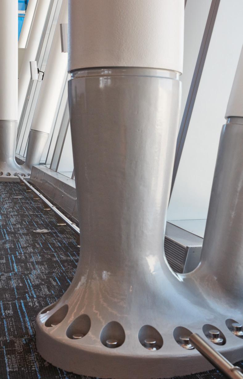
e steel casting design and manufacturing process allows project teams to achieve freeform connections and shapes that may be difficult to accomplish with traditional fabrication methods. Advanced methods in finite element analysis, metallurgy, and manufacturing allow for creating large or small customized designs for signature projects with higher-level aesthetics and high structural performance (high wind, high seismic, fatigue, etc.). In addition, the casting supplier can work closely with the steel fabrication and erection


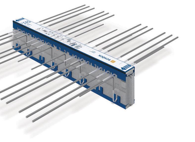
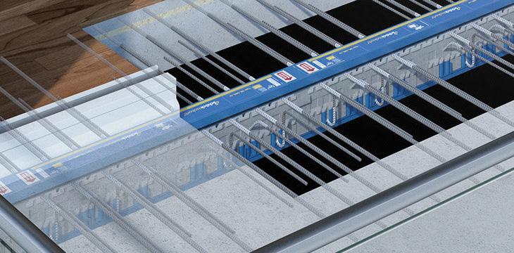
g Prevent condensation and mold g Improve effective R-value of the building envelope by up to 50% g Increase floor temperature by up to 34°F/19°C adjacent to balcony g Reduce heat loss by up to 90% g Meet code requirements for continuous insulation with maximum effectiveness
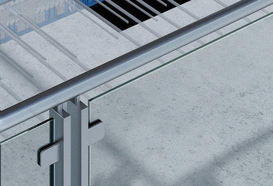
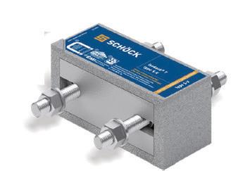
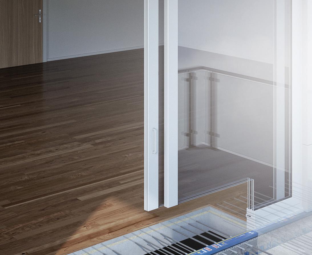
Isokorb® Structural Thermal Breaks prevent condensation and mold, and reduce energy consumption by insulating balconies, canopies, beams, slab edges, parapets and rooftop equipment where they penetrate the building envelope.


Proud to offer Passive House, UL and ICC approved products. www.schoeck.com


teams to include fabrication and constructability features that can provide additional labor savings.
Project teams looking for pre-engineered off-the-shelf products for AESS/AESSS connections can consider a number of the stan dardized cast steel products currently available on the market. The off-the-shelf solutions provide design and aesthetic certainty to the design team and owner on the connection’s quality. In addi tion, standardized cast connection suppliers can provide physical samples or digital renderings for AESS/AESSS mockups when the contract documents allow. This helps accelerate project schedules using higher, or custom, AESS/AESSS categories.
Other AESS/AESSS casting considerations include:
• Complex geometry – when connection configuration limits the use of standard fabrication and erection tools.
• Increasing the list of steel bidders – steel castings reduce the need for specialty fabricators or erectors for a project, opening the opportunity for more steel teams to participate on a project.
• Complex Construction – customized and standard castings provide simpler bolting and welding con nections for a project that can be easily erected and remediated.
Project teams are encouraged to consult with a qualified casting supplier early in the design process, allowing the design team to understand options to leverage castings and receive budget pricing.
While the AISC Code of Standard Practice considers steel castings as “Other Steel, Iron or Metal Items,” project teams can use the AESS/AESSS category system when specify ing the aesthetic goals of steel castings. The authors encourage project teams to use a Custom Category to create a customized AESS/AESSS system that enhances the project budget and ensures the fabrication, erection, and finishing of the AESS/AESS and steel casting goals are met.
The use of exposed mass timber with AESS/AESSS is on the rise in steeltimber hybrid buildings. However, as with all hybrid AESS/AESSS framing systems, there are a few considerations that project teams must consider.
Those items include:
Matching Tolerances – Higher AESS/AESSS categories have tighter tolerances often overlooked for adjoining timber framing.
Paint/Coating Application – The design and construction teams must make an early determination for when the painting or coat ing system application will occur (shop application or on-site). In addition, teams should note if painting and coating systems can be present on steel to timber faying surfaces.
Scope of Work – AESS/AESSS elements attaching directly to mass timber elements may be under the scope of the timber supplier, who, in turn, may sub-contract steel fabrication work, or a steel fabricator may be contracted directly by the GC. Coordination between the two trades must be considered to successfully meet the desired AESS result.
Designers are encouraged to use the AESS/AESSS Custom Category (AESS/AESSS C) to help provide the most consistency between the adjoining exposed framing materials. Numerous custom categories are allowed on a project; therefore, teams can use the category flex ibility for mass timber and AESS projects.
Hot-dip galvanization is a low-main tenance corrosion prevention coating for AESS in exterior and harsh envi ronments. The AESS category system does not address secondary paint and coating systems of exposed structural steel. To assist project teams in the sec ondary galvanization process of AESS, the AGA created the Hot-Dip Galvanized Architecturally Exposed Structural Steel Specifiers Guide .
The new guide provides a comprehen sive overview of how designers can meet corrosion resistance and aesthetic goals for galvanized AESS. The AGA guide is tailored to the AISC and Canadian Institute of Steel Construction’s (CISC) AESS categories. It provides a sample AESS category matrix emphasizing the use of the Custom Category (AESS C). In addition, the guide helps specifiers understand how traditional fabrication practices can impact the final appearance of galvanized steel.
While desirable, the reality is that not every project budget allows for the additional steel craftsmanship required for AESS/AESSS. When project budgets are tight, designers can consider options to enhance the aesthetic of exposed standard structural steel:
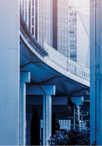



Let the context of the steel determine if AESS/AESSS is necessary – By nature, those in construction are very aware of structure regardless of the finish. However, for some building occupations, the end-users are drawn to other features/usages in a project (think steel sports arenas). Additionally, suppose the steel is far from view, covered by partitions, or is in a lower traffic area. In that case, project teams can use geometry and massing of the steel shapes to create a higher aesthetic without AESS/AESSS requirements.

Hide imperfections with paint or coatings with a matte finish and lighter color palette – Darker and shiny coatings emphasize surface imperfections. To mask minor imperfections, consider a lighter matte color palette for exposed steel (think apartment wall colors that hide considerable repairs). With minor imperfections hidden in plain sight, the project team can reduce the need for extensive surface preparation or connection touchup beyond what is necessary for the adhesion of the selected paint or coating system.

Consider HSS sections for closeto-touch exposed steel – Overall, HSS sections require less paint/coating when compared to WF shapes. Coating system failures propagate from sharp corners; for high-traffic areas, coating system performance is better for HSS due to the reduction of sharp corners compared to WF shapes. Consider blind fasteners for bolted connections – Blind fasteners can give the HSS to HSS connections a clean look akin to a remediated welded connection. In addition, bolting in the field is more economical than welding in the field. us, the use of bolted construction overall and blind fasteners for HSS can help achieve an economical AESSlike look.


e AESS/AESSS Category systems and industry resources provide the foundation for economically expressing exposed structural steel, structural stainless steel, and hybrid framing systems. And when AESS/AESSS questions arise, project


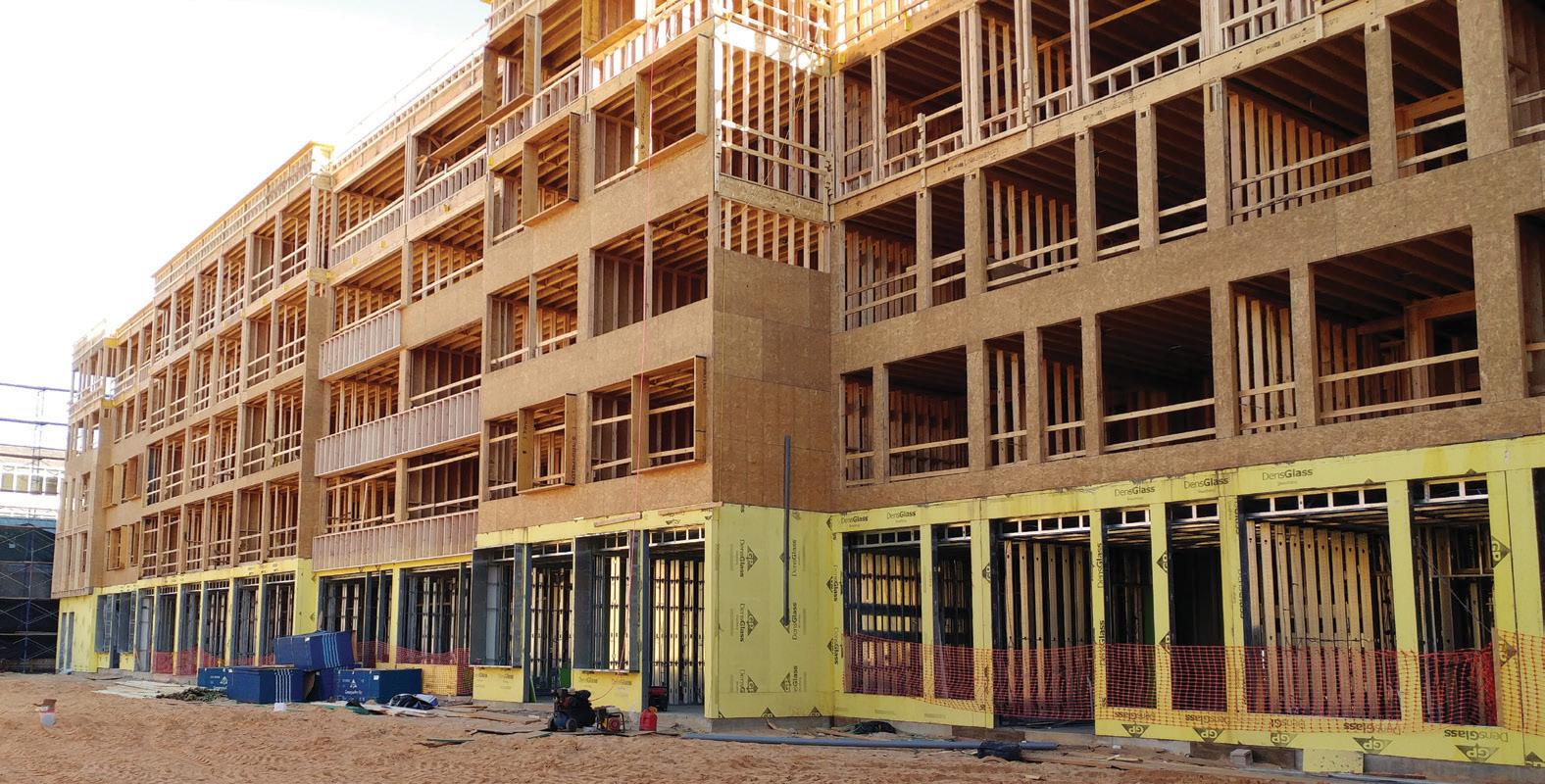
Developers are always looking for new and innovative ways to make buildings more profitable and financially efficient. Traditionally, a multi-story bearing wall building over one to two levels of steel or concrete, also known as a podium structure, has filled this need by offering high-density residential units at the upper levels and parking or retail spaces at the lowest floors. For multi-story residential build ings, wood construction is generally considered the most cost-efficient form of construction, followed by cold-formed steel (CFS) bearing walls and then heavy steel or concrete fram ing. Because of this, developers have sought to maximize the number of wood-framed floors over the podium level before switching to more costly materials.
Wood bearing wall systems are limited to either 4-stories using Type V-A construction or 5-stories using Type III-A construction. Both types of construction can be supported on grade or a podium structure. Podium structures have been covered extensively in previ ous articles by STRUCTURE magazine. They are proven methods of meeting not only financial requirements but zoning and regulatory obligations as well. This article focuses on an alternate hybrid system that maximizes the number of stacking levels of residential units by introducing multiple levels of CFS bearing walls to support the woodframed levels before transitioning to the transfer level or foundation.
Recently, some developers have opted to add additional residential units below the Type V-A and III-A constructed units. This means the stacking residential units from above are carried down below the podium level by minimizing or removing the retail and parking areas altogether. This change increases unit density, thus maximizing more profitable areas by limiting the less profitable retail and parking areas.
The challenge with incorporating stacking units from above with a typical steel or concrete podium superstructure is the interference of regularly spaced columns with residential unit layouts. While the podium column scheme lends itself well to open spaces required for retail and parking, the standard grid pattern presents architectural challenges at residential levels in accommodating columns within the unit layouts. Additionally, non-stacking loads from the residential bearing wall system above inevitably require deep steel or concrete beams or heavily reinforced concrete slabs and may even require drop panels. The ideal column grid may also disrupt stacked window layouts along the exterior of the building below the podium level.
Architecture is not the only discipline to face challenges with this system. Plumbing, electrical, and HVAC systems are typically
accommodated by having stacking mechanical penetrations for the full height of the building. In a wood-framed building, these are commonly located within the wall stud cavity. Therefore, stacked penetrations running down through the steel or concrete podium structure invariably conflict with beam and column locations that directly support the walls above.
To resolve these issues, architects frequently need to create new unit types and floor layouts to work around the traditional podium struc tural elements. Unfortunately, the new layouts can create spaces that may be inefficient or undesirable to developers or prospective tenants.
Cold-formed steel framing has a long history of being used for cur tain walls and load-bearing walls for taller residential buildings up to 12-stories when non-combustible framing members are needed for the main structural system. However, for buildings up to 5 or 7 stories in height with podium levels transitioning to more residential use, a hybrid system consisting of CFS bearing walls supporting a noncombustible floor system with up to 4 to 5 stories of wood framing above can be an effective option.
For podium structures, the horizontal separation must meet the criteria outlined in the 2018 International Building Code (IBC), Section 510.2, summarized below:
1) A 3-hour fire-rated horizontal assembly separates buildings
2) The horizontal assembly and the building below are Type I-A construction
3) Shaft, stairway, ramp, and escalator enclosures to be 2-hour rated
4) The building above the horizontal assembly is permitted to have multiple Group A occupancy uses, each with an occupant load of less than 300, or Group B, M, R, or S occupancies
5) An automatic sprinkler system shall protect the building below the horizontal assembly
6) Maximum building height satisfies the limits in Section 504.3
As indicated in items 1 and 2, CFS bear ing walls below the horizontal assembly are a viable alternative to traditional podium framing, which typically consists of steel beam and column construction or concrete transfer slabs.
The advantage of this hybrid system is that the bearing walls can stack and directly support the wood bearing wall levels above. Floor layouts can be main tained with minor adjustments for wall sizes, thus leaving the unit spaces, window locations, and utility locations largely unaltered between the podium and upper floors. A maximum of two levels of CFS bearing walls can be utilized while main taining the height limitations outlined in IBC section 504.3 for either Type V-A or Type III-A construction.
The primary impact on architectural plans is minor dimensional shifts within the units. The 3-hour fire rating required for CFS structural elements supporting podium levels results in drywall thicknesses of approximately 1.5inches to 2-inches thick on the rated side of the wall. Additionally, most bearing walls typically provide CFS studs in sizes of 3⅝-inch, 6-inch, or 8-inch depths. These sizes are larger than the respective nominal wood stud sizes of 3½, 5½, or 7¼ inches. The combina tion of the 3-hour fire rating assembly and larger CFS stud sizes results in slightly smaller units at the lowest level but rarely affects the overall layout.
Isometric view of podium level and wall framing.
of lateral bracing utilized in stacked con struction. The shear walls are located at the corridor and unit demising walls that stack from the uppermost level to the foundation. At the CFS levels, shear walls are sheathed with steel sheets or braced with light gauge X-braces. By utilizing shear walls at all levels, the shear walls can be stacked down through the full height of the building, simplifying the lateral system.
Reinforced vertical masonry cores, concrete cores, or steel moment frames may also be used for lateral bracing. These systems are best used only where needed to accommodate large open areas that do not allow the stacked shear walls to continue down through the building. When cores and moment frames are utilized, special design con siderations are required to ensure the lateral force of the stacked shear walls is transferred to these elements through collectors and chord members. The connection of the diaphragm to the cores or moment frames also needs to be correctly detailed to ensure that the concentrated lateral loads are transferred to the vertical lateral elements.
Regardless of which lateral bracing system is selected, it is possible to use a two-stage analysis as outlined in ASCE 7, Minimum Design Loads and Associated Criteria for Buildings and Other Structures, Section 12.2.3.2, similar to traditional podium buildings. When designed appropriately, the lateral stiffness of the restraint system utilized for the CFS bearing walls can meet these requirements, thus significantly reducing the seismic loads on the wood shear walls.

The mechanical systems used at the wood-framed levels can also be used at the CFS bearing wall level. Vertical risers can be continued down through the wall cavity to the foundation with minimal impact on the framing. Wall stud bridging members and shear wall locations may need to be coordinated with risers depending on the types selected by the structural engineer. Horizontal runs of electrical wiring and plumbing supply lines can fit within the web punchouts provided in standard stud sections. However, the plumbing drains must be placed in furring or wet walls whenever possible, as the required drainage slope may not align with punchout locations. Field cutting web holes in metal studs is not recommended due to more strict limitations on size and location than what is allowed for wood studs. The design standards pro duced by the American Iron and Steel Institute (AISI) may be referenced for further information about acceptable holes in CFS stud framing.
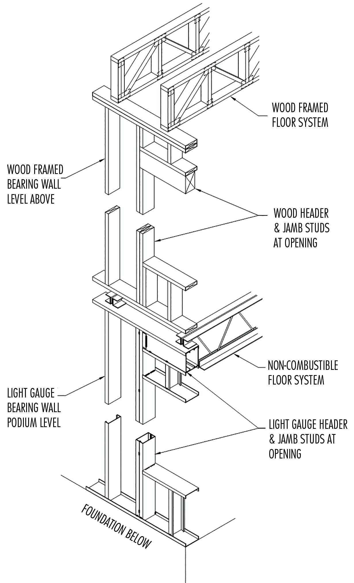
The lateral system used for the wood-framed and CFS levels must be compatible. At the wood-framed levels, drywall or wood structural panel sheathed shear walls are the most common method

A non-combustible 3-hour fire-rated Type I-A floor system serves as the podium level and bears on CFS walls. A CFS bearing wall system allows for various floor assemblies that satisfy the 3-hour fire rating and the finish requirements for residential space. Common types include composite metal joist, precast concrete plank, and deep flute metal deck. Each has its own set of benefits and drawbacks when determining which one is best for a given project. Listing all floor systems and design considerations is beyond the scope of this article. However, general considerations include but are not limited to: com patibility with CFS bearing wall framing, fire rating of the assembly,
Example light gauge bearing wall podium with completed framing.
fabrication lead time, floor profile thickness, maximum shored and un-shored spans, re-shoring requirements, soffit requirements, flex ibility in supporting offset loads, flexibility with field modifications, load distribution member (LDM) requirements, and weight of the floor system. These factors and more need to be weighed by the design team to determine the best option for a specific project. It is also best to involve the general contractor, if possible, to help determine rela tive costs and availability of materials to meet the project schedule.
The overall weight of any floor system presented is often lower when compared to cast-in-place concrete and is similar to a steel podium structure. This is due to the significant reduction in required concrete volume compared to typical reinforced concrete slabs. The lighter system has lower foundation loads that result in smaller footings and reduce the seismic demands on the structure.
On most, if not all, projects, the primary concern for the developer and contractor is cost. The costs of any project can be affected by multiple factors, but the most significant effect often comes from material type and volume. As previously mentioned, the hybrid system is lighter than traditional podium construction methods due to light-framed wood construction at the upper floors and the potential for reduced concrete volume at the podium and foundations. In addition, the reduced seismic demand on the shear walls can result in less expensive or fewer shear walls being required for the structure.
A traditional podium level requires interior partitions for unit sepa ration, corridors, and unit interiors when used for residential units. The CFS bearing wall system takes advantage of this fact by using these walls as the structural support for the building. Walls that would already exist and have drywall or insulation for sound and fire rating purposes can also function structurally. The increased fire rating of 3 hours can be achieved through additional layers of drywall, which do not require specialty contractors to install.
The cost of a project is directly related to the construction schedule. Cold-formed steel bearing walls and the various floor systems offer unique, time-saving options that are generally not available with typical steel and concrete framing. It is possible to stick frame the
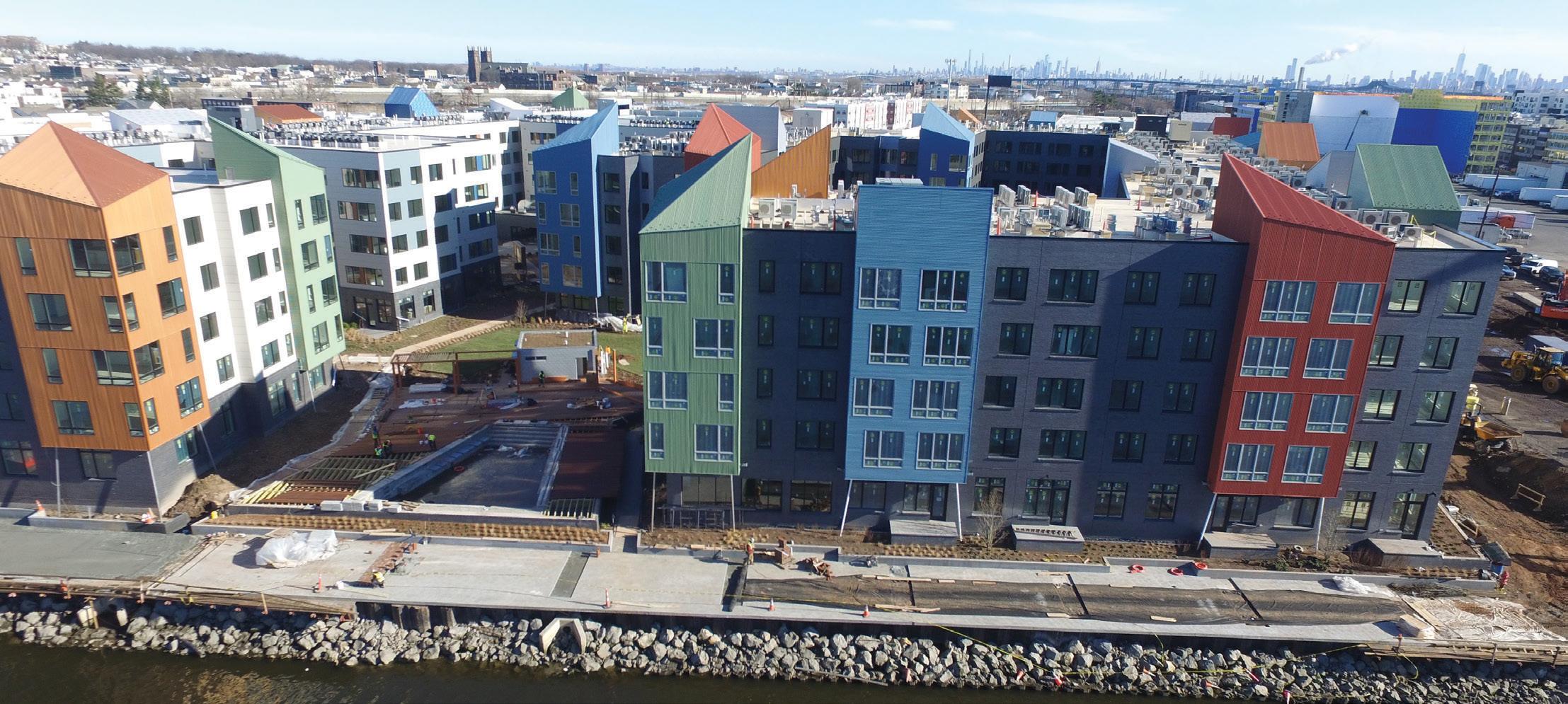
CFS bearing walls similar to the wood levels above. However, the most efficient option is to have the CFS walls panelized in a shop and delivered to the job site ready for installation. Panelizing does require lead time for fabrication but significantly reduces on-site time. Depending on site conditions and project size, entire floor levels may have the walls installed in two or three days rather than weeks. Shop fabrication also offers better quality control and tighter tolerances than field framing. Depending on the selected podium floor system, the erection of the floor may also be faster than comparable steel or concrete framed podiums. Precast concrete plank is fabricated offsite and dropped in with minimal on-site time. Composite joists and deep flute metal deck systems can be placed quickly before pouring the concrete that sits on top. In some cases, proprietary floor systems may be assembled into larger floor panels and dropped into place with cranes. Moreover, these systems typically result in less required floor shoring compared to traditional one-way and two-way concrete slabs.
For buildings where the developer wants to maximize the use of wood framing, but the number of residential floors exceeds the limit for Type V or III-A construction, a hybrid system provides an efficient alternative to traditional podium systems. The hybrid consists of cold-formed steel bearing walls supporting a non-combustible floor system. Architects and developers succeeded with this hybrid system in buildings with stacking residential units. The benefits of CFS panelization, less shoring, and less steel framing can substantially reduce construction schedules and economic costs.
■
All authors are with Mulhern + Kulp Structural Engineering.
Humberto L. Coelho is a Principal & Director of Business Development (bcoelho@mulhernkulp.com).
Kevin Quan is a Senior Project Engineer (kquan@mulhernkulp.com).
Micah Milner is a Project Engineer (mmilner@mulhernkulp.com).

SUBSCRIBE TODAY: An annual subscription that provides users with digital interactive access to ACI CODE-318-19, “Building Code Requirements for Structural Concrete and Commentary,” along with in document access to related resources and enhanced digital search features through all code provisions and commentary.
Includes full digital interactive access to the ACI Detailing Manual and the ACI Reinforced Concrete Design Handbook, subscribers can make digital notes alongside ACI CODE-318-19 provisions and commentary, and navigate content by section, by chapter, and/or by provision.
For access and to subscribe, visit www.concrete.org/ACI318
Last year, the Intergovernmental Panel on Climate Change (IPCC) stated: “It is unequivocal that human influence has warmed the atmosphere, ocean, and land... Observed warming is driven by emis sions from human activities. The scale of recent changes across the climate system as a whole are unprecedented over many centuries to many thousands of years.” Of course, these emissions are a product of global society as a whole. However, the building construction industry has been a significant emissions contributor and material user; approxi mately 40% of global material extraction is for housing, construction, and infrastructure. As structural engineers, we have a fantastic oppor tunity to be impactful leaders in reducing material use and emissions. Decisions we make to reduce the embodied carbon in our project work can save hundreds of tons of carbon emissions each year. This is orders of magnitude more impactful than decisions we make in our personal lives – such as driving less or taking fewer flights – which can save a few tons of carbon emissions each year. This article discusses the potential to reduce greenhouse gas emissions by defining a Circular Economy in the architecture, engineering, and construction (AEC) industry, reviewing key case studies that implement Circular Economy principles, and outlining future goals of the Structural Engineering Institute (SEI) Sustainability Committee’s Circular Economy Working Group.
The emissions associated with material use are primarily related to the current industry paradigm: a linear economy. A linear economy in
construction can be categorized by a take-make-waste model (Figure 1), where raw materials are extracted (take) and processed into construction materials for use in our built environment (make). At the end of life, structures are demolished, and the materials are typically discarded to landfill or, more commonly, downcycled (waste). Each of these stages emits greenhouse gases: energy use for extraction, energy use and chemi cal reactions during processing, and fuel use in transporting materials from different locations throughout the material and construction lifecycle. This linear economy is common for construction materials such as concrete, brick, or timber, where the material is often processed into subbase or mulch with a much lower value. Metal construction materials at their end-of-life are typically recycled (a large loop economy). While this is a vast improvement over landfill, the recycling process is a large loop that still requires energy contributions for sorting, processing, and transporting before following the process of refining and producing elements again from scratch (Figure 2).

In contrast to a linear economy or large loop economy, a circular economy in construction aims to minimize waste and emissions by reducing the need for new materials and fabrication processes through tighter construction material loops (Figure 3). The primary goal is to extend the use of a structure through renovation, refurbish ment, and re-purposing – extending the length of the use phase. Where this is not possible, and a structure comes to its end of life, a circular economy model allows for the repair, reconditioning, reuse, and refurbishing of existing elements, and designing new structures and components for longer lifespans and better reusability

Figure 1. A linear economy in construction.
Figure 2. A large loop economy in construction.
and repair from the outset. These changes from a linear to a circular economy model can reduce the emissions associated with material extraction, processing, and transport. These changes can also provide economic benefits if realized, particularly in a world where energy and fuel costs are increasing and volatile. As the Circular Economy Working Group for the SEI’s Sustainability Committee, we use the following definition:
A circular economy is one that keeps or elevates structural products, components, and materials at their highest utility and value across multiple life cycles within the building stock. Through maintaining structural elements at their highest utility, we can: reduce greenhouse gas emissions associated with manufacturing new structural elements; minimize impact on natural environments caused by new material extraction; and, for biogenic materials such as wood, continue to sequester embodied carbon for longer.
This circular economy definition focuses on the reuse of individual products, components, and materials, as opposed to the reuse in place of complete systems like buildings or bridges. The refurbishment, adaptive reuse, and retrofit of existing structures – where compo nents are maintained in place – is an essential part of implementing circular economy principles in the AEC industry and is well cov ered by other groups, such as the Structural Condition Assessment and Rehabilitation of Buildings SEI Codes and Standards Activities Division committee. In most cases, maintaining a structure in its current use with most of its materials in place leads to the smallest greenhouse gas emissions. However, in scenarios where maintaining an existing structure in place is impractical, circular economy prin ciples applied to a structure’s individual components are important. Implementing a circular economy in construction is a very achiev able goal. Indeed, for most of the history of construction, dismantling derelict structures to reuse the components in new buildings was not unusual. This stretches from St Peter’s Basilica in Rome, Italy, which was partially constructed using stone salvaged from the nearby Colosseum, up to early 1900s construction in NYC and Chicago, where buildings were routinely manually disassembled, with their bricks, timber joists, and structural steel parts stockpiled and sold for reuse in new structures. In previous contexts, using available salvaged structural materials – instead of paying to manufacture and transport new materials – was part of standard practice and incentivized by lower structural material costs for reused elements. However, demolition practice began to change at the end of the Gilded Age when the speed of building removal was emphasized in place of opportunities for salvage. Examples include the demolition of the 20-story Gillender building in NYC in 1910. By the 1950s, the methodical manual labor that allowed materials to be processed

for reuse was replaced with heavy machinery (such as wrecking balls and bulldozers), reducing the opportunities for reuse. The widespread mechanized demolition ushered in by the Housing Act of 1949 and the Federal Aid Highway Act of 1956 could be seen as marking the transition from the previous period of a more circular economy in construction to that of a linear one.
These changes in demolition practice were accompanied by changes in the AEC industry related to the development of building codes and construction material specifications. In 1922, before these changes took place, the Building Code of NYC discussed methods for reus ing old bricks in new construction and explicitly noted that old steel and wrought iron shapes could be reused. The American Engineering Standards Committee was only founded in 1918 and had a limited scope of influence. Today, ASTM standards are diverse and numerous, and building codes typically specify new material that meets these standards. The importance and value of building codes and specifi cations to the industry and society are evident. Still, one side-effect of the codification was the preference for certification that controls new industrialized manufacturing processes instead of processes that enable reconditioning and recertifying existing materials. This can become a barrier to re-implementing circular economy principles in the industry today. Extensive material investigation and testing are required to reuse existing materials that lack documentation, such as steel mill certification, to meet standard specifications such as ASTM A500 for chemical composition and material strengths. Many changes away from the status quo linear economy model of material specifica tion, element design, and new material procurement bring a similar potential for increased uncertainty and associated increases in cost. While barriers to re-implementing a circular economy exist, they are not insurmountable. Structural engineers making design decisions on element sizes and material specifications have a fantastic opportunity to explore circular economy principles in our work and realize some of the carbon emission reductions available to us. In addition to the his torical precedent and environmental motivation, the global economy may assist in this new transition from a linear economy back to our previous circular one. Since 2020, the pressures on supply chains and transport logistics have led to high and unpredictable material prices. As a result, the ratio between material and labor costs is changing. In partnership with a global imperative to reduce greenhouse gas emis sions, this economic pressure could lead to a construction ecosystem where a linear economy reliant on a steady supply of new material is not desirable or economically viable.
Fortunately, the principles of circular construction are still at the heart of our profession. Engineers work to a client’s brief and within project constraints to solve problems; our role is essentially as a
resource manager, balancing costs, time, and material use as best we can while fulfilling the project. To address the climate emergency, we can re-prioritize these resources, with a renewed focus on materi als – and their associated greenhouse gas emissions – in addition to time and cost. As engineers, we can continue to react to economic pressures, but we can also proactively be involved in discussions to implement changes in legislation and practice to focus more on material lifecycle management and specification. For example, we could design for sustainability as well as serviceability and strength. The structural engineering industry is already proactively addressing our impact on greenhouse gas emissions through initiatives such as SE2050; however, there are further opportunities for us to spe cifically address material life cycles through implementing circular economy principles.
While circular construction practices have become less common, they are not unheard of. Existing case studies can be valuable examples of the potential for material reuse and design for deconstruction. In addition, they can be used to demonstrate to design teams and clients that perceived barriers to reuse or design for deconstruction can be overcome. There have been several projects completed in the last 25 years that successfully demonstrate either (1) the reuse of materials in new construction or (2) the design for deconstruction (DfD) of new structures to facilitate future material reuse at the structure’s anticipated end-of-life. The following highlight a few case study examples for different primary construction materials extracted from an expanding database of benchmark circular economy projects cur rently being collected by the Circular Economy Working Group. You can find additional information on many of these examples in the list of references (see the online version at STRUCTUREmag.org).
First, case studies that reuse existing material in new construction and facilitated by construction techniques with discrete elements that can be connected, disconnected, and reconfigured. This typically prefers
frame or panel construction from steel, timber, or precast concrete instead of monolithic construction from cast-in-place concrete.
The Mountain Equipment Co-op in Ottawa, Ontario, is a commercial building constructed in 2000. The steel structure on the site was decon structed, and components were reused to construct the new steel frame. On the scale of local infrastructure instead of buildings, Muskingum County Engineers Office in Zanesville, Ohio, has reused existing steel beams from previous projects to construct seven new bridges between 16 feet and 55 feet between 2007 and 2015. Concerted industry efforts in the United Kingdom have led to a recent drive to normalize the use of reused steel in new construction, with the publication of the practical design guide Structural Steel Reuse by the Steel Construction Institute in partnership with Cleveland Steel and Tubes Ltd.
As demonstrated by the Eglisau bridge, timber elements have been reused successfully for centuries. A successful example of timber reuse has been the Wilson Farm barn in Lexington, Massachusetts, completed in 1996. This incorporated the use of timber from former U.S. army facilities and commercial factory buildings, among other locations. An in-depth body of research has been completed by the U.S. Department of Agriculture Forest Products Lab in Madison, Wisconsin, to propose methods to enable salvaged wood to be reused, although commercial barriers remain to reuse. Recent research by the InFutUReWood group explored the obstacles to salvaged timber reuse and focused on reusing material in laminated engineered wood products.
As a heavy frame or panel material, precast concrete has not featured in material reuse projects as frequently as steel or cast-in-place con crete. However, some successful case studies have been conducted, such as the Plattenpalast art space constructed in Berlin, Germany, in 2009. The design utilized standardized concrete panels from a standard construction type and reconfigured them with new connec tions to form a new structure. In addition, recent research at École Polytechnique Federale de Lausanne proposed the manufacture of new precast concrete blocks by cutting them from existing cast-in-place concrete elements and connecting them instead of reusing previous precast concrete elements. Considering the quantity of cast-in-place
concrete in our built environment, this seems a challenging but potentially high-impact approach.
Secondly, new construction that is designed for future deconstruction can be considered. In contrast to material reuse in construction, design for deconstruction projects plan for potential future material reuse while still utilizing conventional material workflows for the initial construction. is removes a number of the certification and supplychain obstacles to material reuse. However, it relies on future favorable deconstruction and reuse practices that take advantage of the initial design and delays the opportunity to benefit from the circular economy until the building’s end of life instead of at the structure’s outset.
A recent exciting large-scale example of steel design for deconstruction is Stadium 974, one of the soccer stadiums constructed in Qatar for the 2022 World Cup. is stadium is envisaged as a bolted modular steel frame that can be easily dismantled, transported to alternative locations, and reconfigured into a series of different smaller stadium-style structures.
e use of precast concrete elements in design for deconstruction projects benefits from commercial development in embedded bolted connection systems. An interesting innovation for Circle House in Aarhus, Denmark, is the use of a lime mortar to seal around the metal hardware fixings instead of conventional cement grouts. Using a lime mortar allows for removing the sealant for deconstruction as opposed to the more permanent cement alternative.
Timber construction designed for deconstruction requires a focus on discrete reversible connections. ese can vary from traditional bearing joist hangers and column head interfaces, removable fasteners such as screws, or interlocking carpentry solutions from Japanese or Western traditions, as demonstrated in much of Kengo Kuma’s work. Modern mass timber frame construction, such as the Bullitt Center in Seattle, Washington, utilizes metal plate connectors screwed between columns and beams to allow for potential deconstruction and element reuse with limited damage.

Existing case studies that implement circular economy principles in construction are an essential basis for sharing lessons from successful projects – located in North America or other regions. ese case studies can teach us how existing barriers to the circular economy model can be overcome, whether through demonstrating the material recertification, laboratory testing and warranties, or showcasing innovative technical design solutions. However, the SEI Sustainability Committee Circular Economy Working Group would like to do more to foster a supportive base to allow all design professionals to advocate and implement circular construction in their work. e Group believes this requires some additional work.
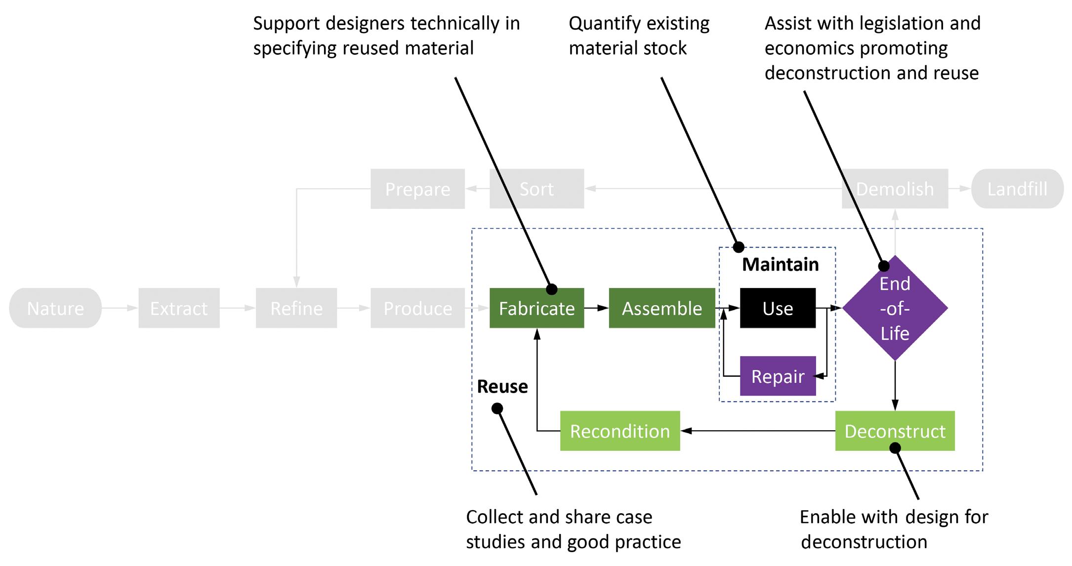
e Circular Economy Working Group intends to focus its work at the level of structural components (i.e., beams, columns, truss elements) instead of complete systems (i.e., buildings, bridges) through the pursuit of design for deconstruction and element reuse as opposed to renovation or refurbishment, or Design for Adaptability. e objectives of the Circular Economy Working Group (Figure 4) are to:
1) Quantify the structural components within our existing built environment, which could become available for future reuse, focusing on common and repetitive structural typologies to guide circular economy efforts.
2) Maximize reuse of existing construction materials, promote deconstruction over demolition, and facilitate design with reused materials.
3) Facilitate future deconstruction of structures by promoting Design for Deconstruction methods, and good-practice project specifications.
4) Assist with introducing a legislative framework for promoting Circular Economy practice in the construction industry through proposed policy and local ordinances.
5) Collect and share case studies and good practices from previous projects that have been completed which align with Circular Economy principles.

e need to change from a linear economy in construction to a circular economy is clear and pressing – a change in how structural engineers design and specify materials in our projects can significantly reduce the greenhouse gas emissions associated with our work. Unfortunately, the AEC industry changed in the latter part of the 20th century to a more linear economy which has accumulated practices that are now barriers to implementing circular economy principles easily and cost-efficiently. But, crucially, the barriers to this change are not insurmountable, and, as structural engineers, it is our responsibility to do more to facilitate the transition back to a circular economy. e Working Group looks forward to implementing this change together. If you have information to share regarding any of these five objectives, please contact the SEI Sustainability Committee Circular Economy Working Group at the author’s email address.■
References are included in the PDF version of the online article at STRUCTUREmag.org

 By Bryan G. Cortnik, MS, P.E., S.E.
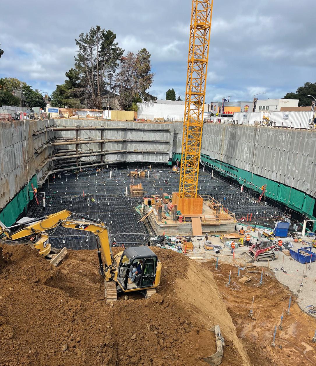
Temporary and permanent shoring is often a necessary factor when designing/constructing new building structures in urban areas. The National Council of Structural Engineers Associations’ (NCSEA) Excavation Shoring Design Guide was created and published to aid structural engineers by providing a single source document. The Guide incorporates all the available codes from the federal government and state agencies so engineers can adequately guide the design team and owners to have the most economical project.
To understand shoring and what it entails, one must briefly go back in time and understand why shoring-related work began. In the early history of shoring, most buildings were not complex and usually con sisted of perhaps a single story below grade. Construction methods were either open cut and then backfilled or some simple low-level temporary earth retention system. In those days, the project civil engi neer acted as the geotechnical engineer, land surveyor, and building engineer and had to design all aspects of the building structure. As technology improved to aid in the design of building structures, and as high-density housing/ multi-story commercial buildings became the norm in urban areas, temporary earth retention systems were required for the following reasons:
1) Environmental Concerns
2) City Requirements
3) Project Cost Viability
4) Parking Requirements
5) Advances in Below Grade Ventilation Systems
6) Advances in Building Structure Modeling
Environmental concerns and city requirements almost always go together (Items 1 and 2 above). As property in urban areas becomes limited due to high demand, all available properties, no matter the below-grade condition, are developed if they comply with all City rules and regulations. Most of these sites are around below-grade city infrastructures, sensitive utilities, and high-ground water tables that are not allowed to be de-watered or on or near contaminated sites. Shoring design needs to become complex to address these issues and concerns. Soil-cement mixing (SMX), also called deep soil mixing (DSM), was developed in Japan and Europe; SMX finally came to the United States about fifty years ago. It was initially used for ground improve ment and levee strengthening; it now has migrated into temporary and permanent shoring applications. SMX has become the most viable option for creating a continuous shoring wall that supports the excavation and provides a hydraulic/contaminate barrier when adequately constructed. SMX columns are installed by injecting and blending cement into the soil using a drill rig equipped with single or multiple augers/paddles or a specialized proprietary cutter head. The soil is mixed with the binder material(s) in situ, forming continuous, overlapping soil-cement columns or a continuous wall of uniform thickness. Steel beams are placed in the soil-cement columns to pro vide rigidity. The SMX system, combined with steel soldier beams and tiebacks (if allowed), serves to shore the excavation and cut off lateral groundwater flow, thus reducing the amount of de-watering required from within the excavation. Soil-cement walls are considered temporary, and permanent building walls are built inside the soilcement walls following waterproofing application.
As the technology developed to meet the demand for construction in high-density urban areas, the demand for deeper cuts increased, resulting in the advanced state of the technology available to us today. In the face of the increasing need for highly developed exper tise, engineers began to specialize in narrower fields of practice. As a result, a vacuum was created for soil retaining structure design work between the geotechnical engineer and the building structural engineer. Both the geotechnical engineer and the structural engineer believe that designing the temporary earth retaining structure related to the excavation of the building site is not their responsibility. They believe the excavation and shoring work is a means and method for the general contractor to incorporate into their work. As a result, many structural engineers strictly limit their scope of work to the design of the building only, with all other services excluded. In addition, most geotechnical engineers consider the design of retaining structures to be the responsibility of the structural engineer and is not within their field of expertise.
That said, designing soil retaining structures has become a specialized field for a group of engineers who are either working with a special ized shoring contractor or frequently exposed to this kind of work. This article summarizes the big picture of shoring and reviews the different types of analysis for both cantilever and restrained systems. In addition, the Excavation Shoring Design Guide is briefly reviewed for use when designing a shoring system for a building structure with either a single level below grade or multiple levels below grade; here is a checklist of items to consider before starting your initial design.
1) Excavation concerns, such as: how deep is the excavation? (Waterproofing concerns? Is a construction slab required? Does the engi neer need to account for over-excavation due to poor soil conditions?)
2) Understand subsurface stratigraphy.
3) Groundwater table (secant or non-secant system); refer to Figure 1 for a temporary secant shoring project.
4) Is the new building structure a full lot line construction? Does the property allow the temporary shoring system to be installed on the project property?
5) What type of structures are located around the excavation (trains, existing building structures, and their foundations, etc.)?
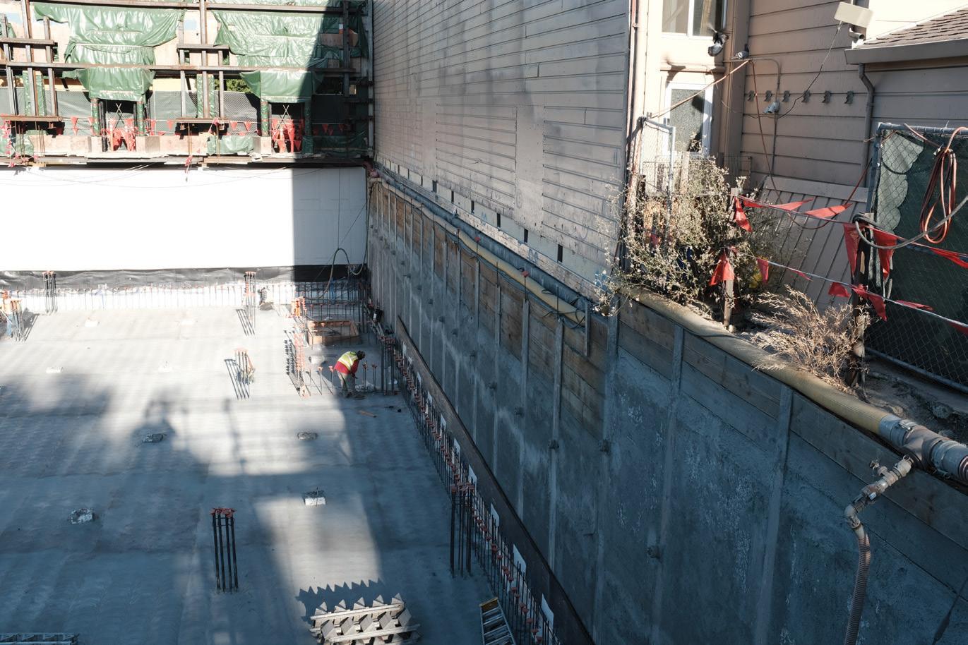
For example, refer to Figure 2 for underpin ning an existing three-story structure and suspending a historic façade required to remain in place.
6) What are the existing site utilities (street utilities, public utility easements that may run adjacent to project property)?
7) Are you allowed to encroach into the Public Transportation Right-of-Way (ROW)?
8) Will you be encroaching into any public transportation zone of influence? Do you need to account for their specific loading requirements?
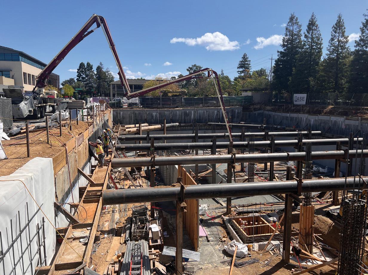
9) Understand encroachment agreements of your local or state jurisdiction; are tiebacks allowed? Does the agency charge a fee to install a tieback into the public ROW? Refer to Figure 3 for an internally braced project where tiebacks were not allowed in the public ROW.
10) Can you lay back the site? Can excavated material be stored on-site, or does it need to be hauled off-site?
Once the scope of the project is understood, requirements can be established, including all geometry, external loading conditions (temporary and/or permanent, seismic, etc.), performance criteria, encroachment limitations, and construction constraints. The items outlined below are a step-by-step process typically followed for the chosen shoring system:
1) Evaluate site subsurface stratigraphy and relevant properties of in-situ soil and rock.
2) Evaluate design properties, establish design factors of safety, and select a level of corrosion protection.
3) Select lateral earth pressure distribution acting on the back of the wall. Add appropriate water surcharge, traffic/construc tion surcharge, and seismic pressure and evaluate total lateral pressure. A staged construction analysis may be required for walls constructed in marginal soils.
4) Determine if ground anchors can be used or if internal brac ing is required.
5) Calculate horizontal ground anchor loads and wall bending moments if ground anchors can be utilized. Adjust vertical anchor locations until an optimum wall bending moment distribution is achieved. Determine if ground anchors need to be de-tensioned; if they need to be de-tensioned, they need to be located to minimize the effect on the below-grade structure.
6) Evaluate required anchor inclination based on right-of-way limitations, location of appropriate anchoring strata, and location of underground structures.
7) Resolve each horizontal anchor load into a vertical force com ponent and a force along the anchor.
8) Evaluate the horizontal spacing of anchors based on the wall type. Calculate individual anchor loads.
9) Select the type of ground anchor.
10) Evaluate the vertical and lateral capacity of the wall below the excavation subgrade. Revise the wall section if necessary.
11) Evaluate the internal and external stability of the anchored system. Revise ground anchor geometry if necessary.
12) Estimate maximum lateral wall movements and ground sur face settlements. Revise the design if necessary.
13) Design lagging systems, design-facing drainage systems, and connected devices.
The next step is to review the different types of analysis for both cantilever and restrained shoring systems. For this article, two different types of shoring systems are discussed: A) continuous shoring walls, such as steel sheet piling, and diaphragm walls, which are typically analyzed on a longitudinal per-foot-of-wall (unit) basis for the lateral pressures, and B) Soldier pile and lagging walls which are analyzed differently than continuous shoring walls. Soldier pile and lagging
walls are designed over the pile spacing above the bottom of the excavation. They are considered discontinuous below the bottom of the excavation. Therefore, the loading acting on the active and pas sive sides of the wall for the embedded portion must be constructed to reflect this discontinuity. The effective width of the embedded portion of the soldier pile (for both active and passive loading) can be computed using the Arching Capability Factor per Table 6-1 of the Caltrans Trenching and Shoring Manual; for example, here is a sample calculation of the effective width.
To determine the passive pressure Adjusted Pile Width (APW), use the following equations E1-a through E1-c.
APW = Pile Diameter × Arching Capability Factor (E1-a)
The Arching Capability Factor, AF, is defined below:
For granular soil: Arching Capability Factor = 0.08 φ ≤ 3 (E1-b)
For cohesive soil: Arching Capability Factor = 0.08 φ ≤ 2 (E1-c) where:
Adjusted Pile Width ≤ pile spacing φ = internal friction angle of the soil in degrees
For this design example, use φ equal to 28° for sandy lean clay; soil clas sification type CL. Input the values into the Arching Capability Factor equation E1-c for cohesive soil. The calculated Arching Factor is 2.4. Arching Capability Factor = 0.08 × φ = 0.08 × 28 = 2.24
Since the number calculated is greater than 2.0, for cohesive soils, use 2.0 to calculate the adjusted pile width.
APW = Pile Dia. × AF = 2'- 0" × 2 = 4 feet - 0 inches
The calculated adjusted pile width is less than the pile spacing and can be used without further adjustment.
Soldier piles are designed as vertical beams to resist the bending moments and shears resulting from the lateral loads acting on the piles. Also, vertical loading (if any) must be considered.
Cantilever walls may be designed using the Simplified method illustrated in Figure 6-3 of the Caltrans Trenching and Shoring Manual. If this method is used, the computed pile embedment depth (D0) must be increased by 20 percent to determine the minimum theoretical pile embedment depth.
The Free Earth Support Method assumes that the shoring wall is embedded far enough to assure stability. Still, the avail able passive resistance cannot restrain the shoring wall sufficiently to induce a negative moment in the wall (i.e., there is no reversal of moment below the bottom of excavation). The theoretical pile embed ment required for stability is determined by statics. The theoretical depth of embed ment needed is determined by summing moments due to all pressures acting on the shoring wall about the point of restraint. The embedment depth is adjusted until the sum of the moments about the point of the restraint is zero. Moments and shears in the shoring wall and the restraint reaction may be computed after determin ing the embedment depth.
The Fixed Earth Support Method assumes that the shoring wall is embedded sufficiently to provide adequate “fixity” at the pile embedment portion of the shor ing wall (i.e., the deflected shape of the shoring wall is such that the wall reverses
curvature over its embedded length). Unlike the Free Earth Support Method, moment reversal takes place over the embedded portion of the shoring wall. Compared to the Free Earth Support Method, the pile embedment computed using the Fixed Earth Support Method is longer; however, pile moment demand, pile deflection, and restraint reaction are typically reduced. Using commonly available structural analysis software (i.e., RISA 2-D or 3-D, Tekla Tedds, Microsoft Excel, or any nodal analysis software), determining the depth of embedment required to produce the appropriate deflected shape of the shoring wall is just a matter of iterating the embedment depth.
The calculated pile embedment depths must be compared against the following suggested minimum values for the three different analysis methods described above:
• Cantilever walls: Pile embedment depth shall not be less than the height of the retained cut
• Restrained walls less than 20 feet in height: Pile Embedment depth shall not be less than 6 feet
• Restrained walls equal to or greater than 20 feet in height: Toe depth shall not be less than 8 feet.

NCSEA’s Excavation Shoring Design Guide provides step-by-step examples covering everything from temporary to permanent cantilever
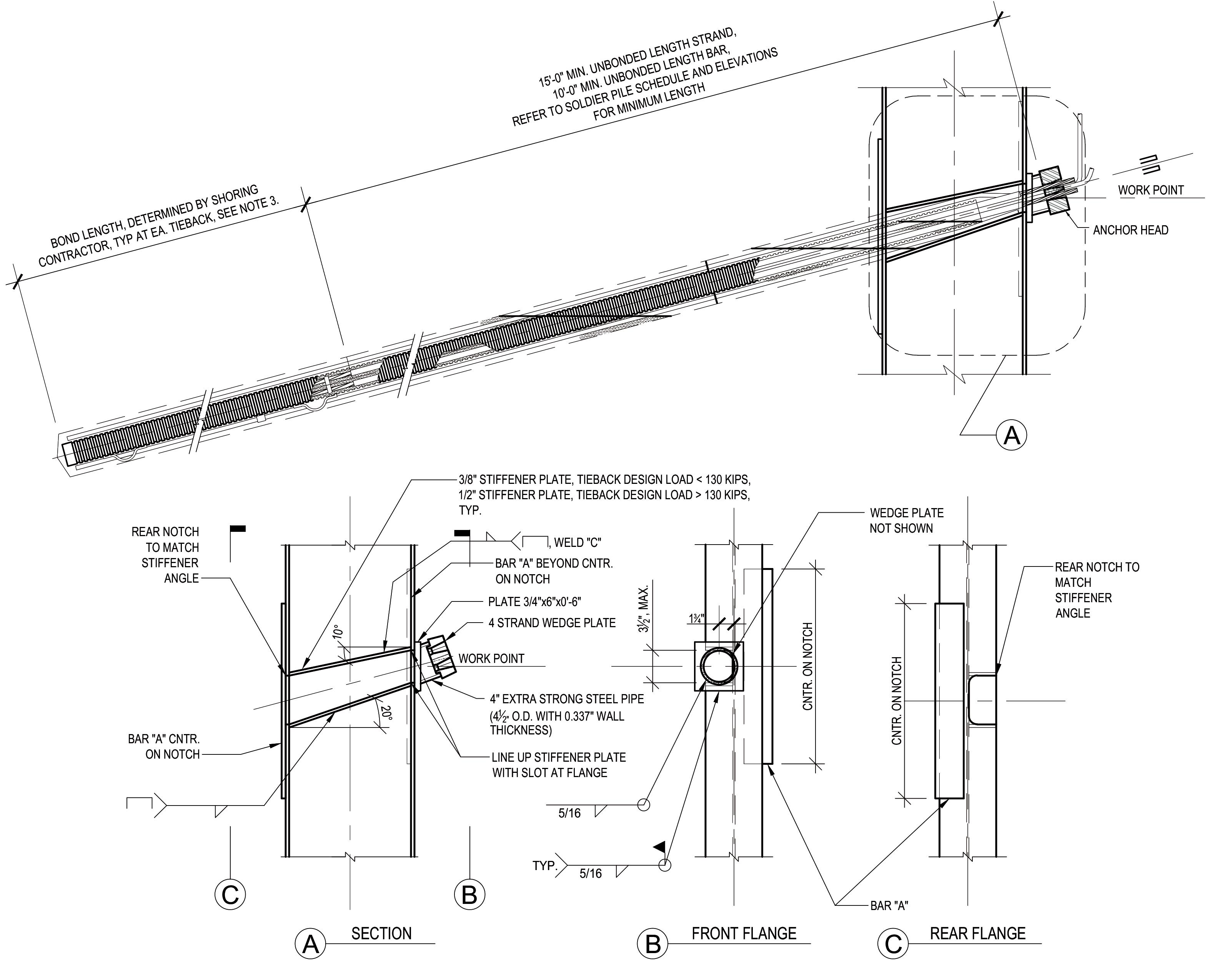
and restrained soldier piles to temporary and permanent soil nail walls. In addition to pile sizing, the Guide covers various lagging systems, provides design provisions for all the primary shoring connections for a restrained approach, and provides real-life construction details. Figure 4 replicates a sample temporary tieback detail from the Guide to aid in construction documents.
To summarize, some major site constraint issues affect shoring design and the significant design steps required to design the tem porary or permanent shoring system. The design of temporary or permanent shoring systems can be just as complex as designing the building structure. Therefore, extensive planning and care should be taken to ensure that the most appropriate shoring system is chosen to provide the most economical system to the owner and the most flexibility to the general contractor to build the new building structure. The NCSEA Excavation Shoring Design Guide seeks to help identify those considerations and provides steps for several different design approaches.
■


 By
By



Red Rocks Amphitheater is considered one of the world’s premier concert venues. Located in Morrison, Colorado, the open-air concept was constructed between a series of sandstone rock formations, creating a natural amphitheater with some of the best acoustics and visuals in the world. When the amphitheater first opened in 1941, the stage was uncovered and exposed to rain and snow, which could arrive at a moment’s notice traveling over Colorado’s Rocky Mountain Front Range. e stage remained uncovered until 1989, when a steel space frame was constructed out of small diameter pipe sections. For 30 years, the original stage roof was functional to shelter performers from the elements. Still, over time, the roof was deemed structurally insufficient due to rigging issues inherent to its design and increased
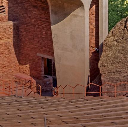
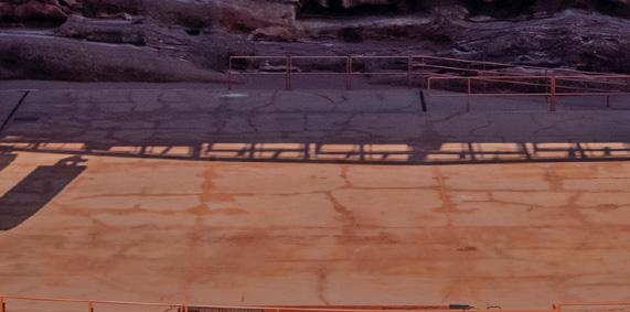

rigging demands as shows became larger from a production standpoint. erefore, the facility owner and the City and County of Denver asked for the complete removal of the existing roof structure and a replacement structure with an increased rigging capacity, which was safer to use and complemented the surrounding setting.
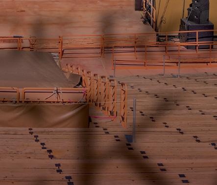
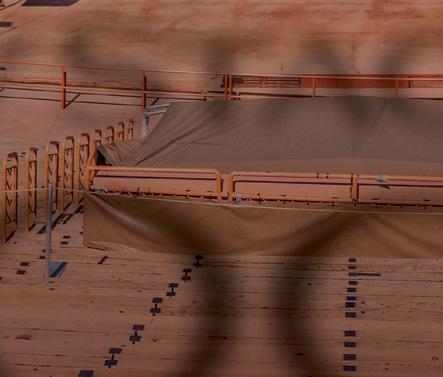
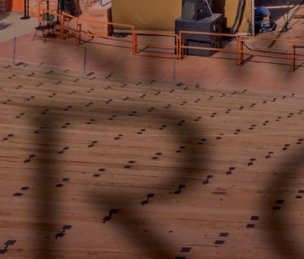
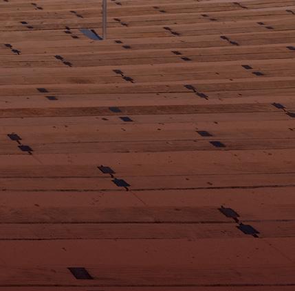
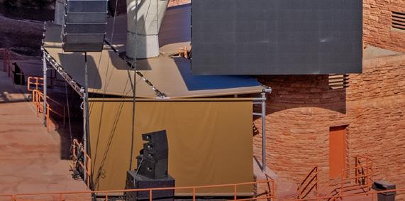
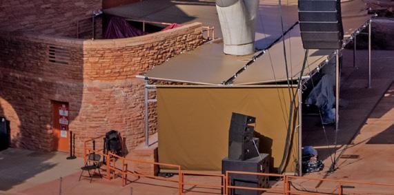
e 1989 roof structure had a rigging capacity of 38,000 pounds – insufficient for the requirements of modern concerts. e original roof framing required temporary concert point loads (lights and speakers) to be rigged using cables hung diagonally from stationary roof members, known as bridling. Bridling can be laborious and dangerous for workers as they orchestrate precise supporting point loads tied off to lifelines while climbing the roof framing.
Figure 2.


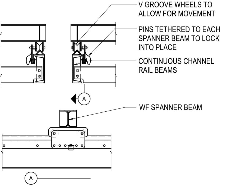
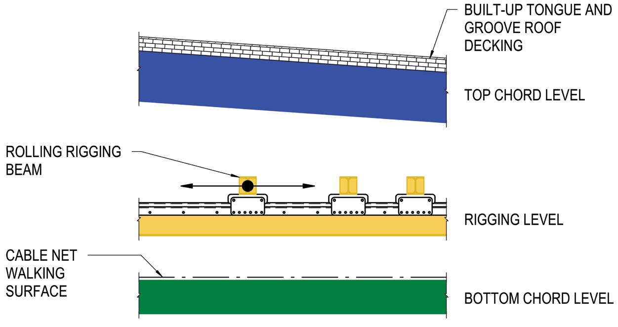
ese factors drove the owner to set new performance criteria, including a minimum rigging capacity of 150,000 pounds and a walking surface with perimeter guard railing to allow workers to safely work within the new roof without fall protection restraints. e new roof structure included an additional 2,500 square feet of coverage to protect as much of the stage floor as possible compared to the old roof’s footprint.
For the new construction, primary and secondary (bridging) roof trusses comprise the main gravity load-resisting system supporting a series of infill steel members. e new roof structure can be divided into three distinct layers (from top to bottom): top chord framing, rigging level, and bottom chord framing (Figure 1).
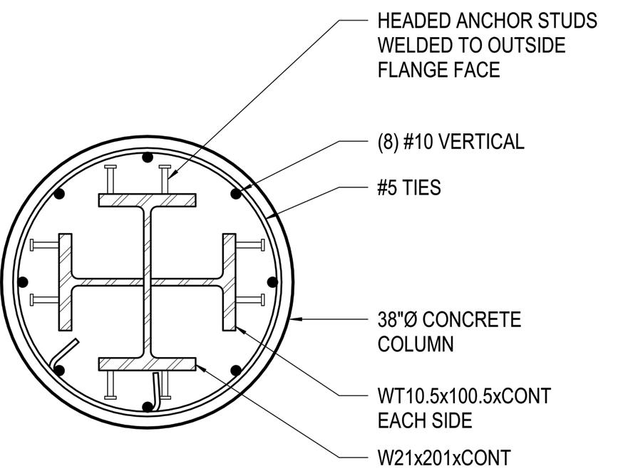
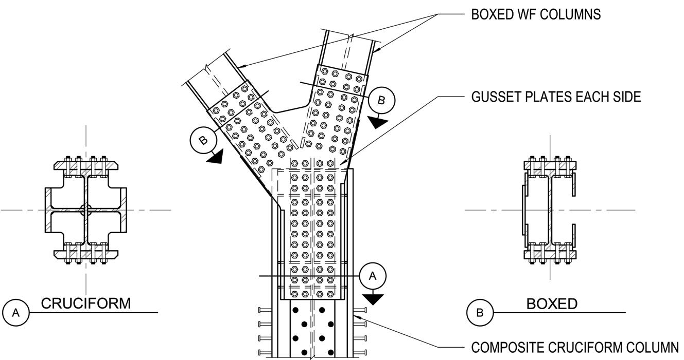
Figure 4. Composite column cross section.


At the top chord level, at the architecture team’s request, linseed oil finished tongue and groove decking spans approximately ten feet between the top chord steel beams and trusses. e decking acts structurally to resist wind, seismic, and snow loading while doubling as the exposed finished surface, further complementing the natural surrounding red rocks. Because tongue and groove decking does not provide high diaphragm shear capacity, a layer of structural sheathing was introduced above the tongue and groove decking, which spans to the lateral load resisting moment frames in each direction.

Moving down to the rigging level, the most critical design innovation incorporated into the new stage roof is its fluidity of rigging configurations. ese configurations were made possible by a series of waist-high




Denver Art Museum Sie Welcome

Denver, Colorado





The structural design of the Denver Art Museum’s stunning new Sie Welcome Center features one of the largest curved, insulated structural glass unit curtain walls ever installed. Renovation of this iconic facility prompted brain-teasing, engaging solutions from the engineering team.
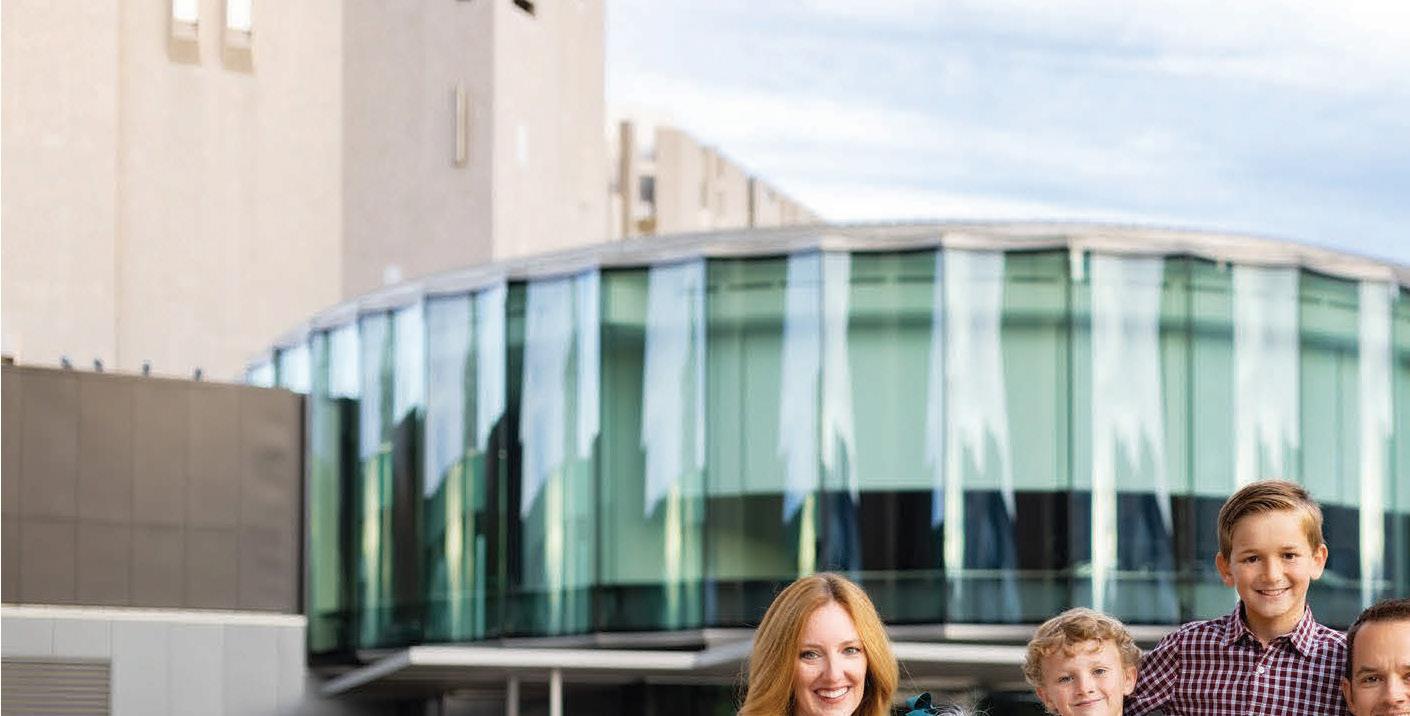
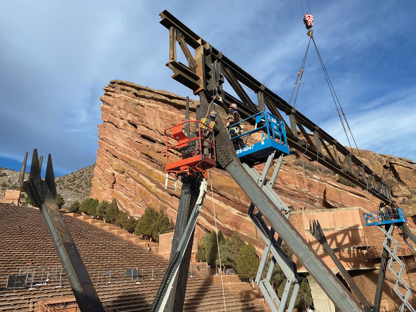
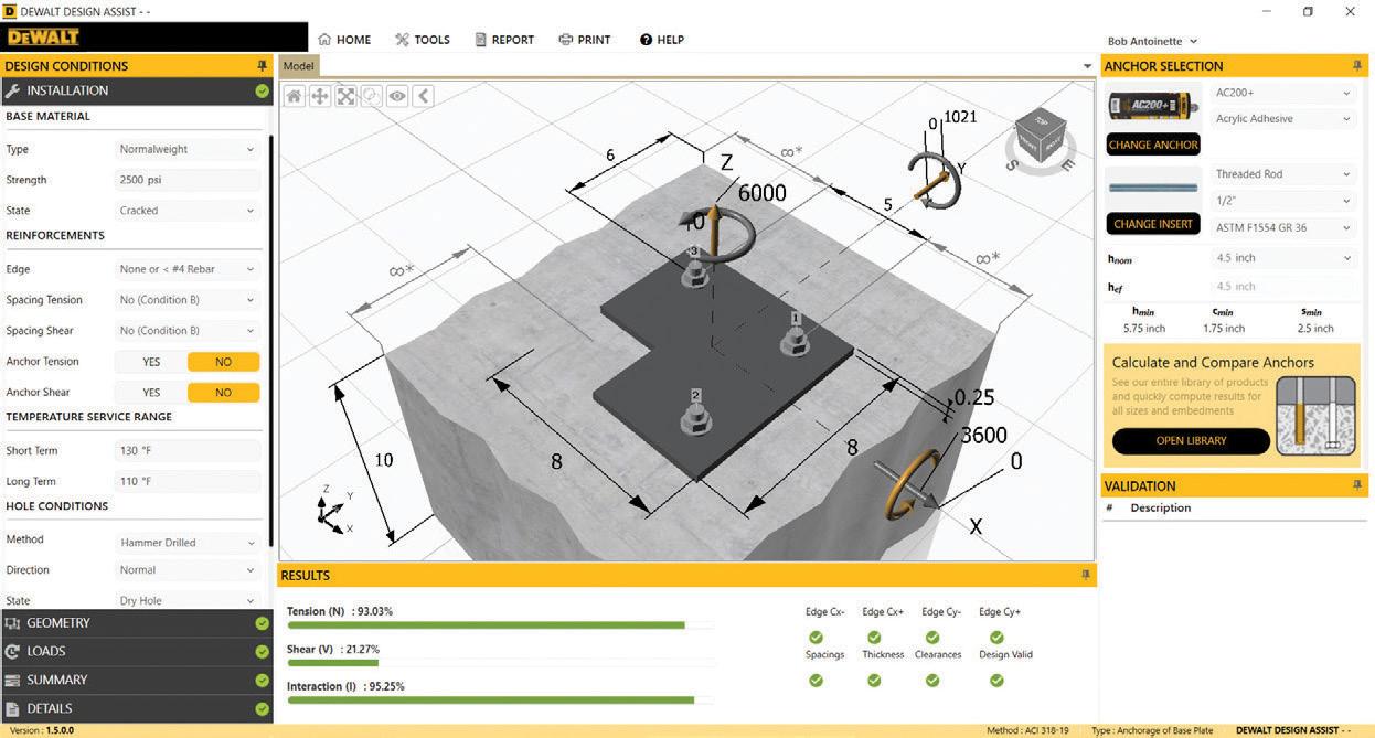
Green room spaces below the stage floor also created challenges in locating the four new columns. e existing stage floor structure is a cast-in-place one-way slab and beam system supported by concrete columns or shear walls. Since these spaces below the stage floor were not reconfigured, column locations were carefully selected to avoid existing concrete beams, shear walls, and columns. is resulted in an asymmetrical configuration but still allowed for pedestrian flow without eliminating any established green rooms.
e new roof structure utilizes moment frames in each direction to maximize open space at the stage floor, with the primary and secondary roof trusses participating in the lateral system for both strength and stiffness. To resist ultimate wind speeds of 170 mph in this special wind region, and because column bending demand increases moving down from the roof structure, the steel column shapes transition from a boxed wide flange shape at the “W” columns to a cruciform steel shape with composite structural concrete wraps at the vertical portion of the columns. Headed studs tie the cruciform steel shape to the concrete causing the two materials to act compositely, gaining strength and stiffness where the bending moments are the largest (Figures 3 and 4 (page 27), and 5 ).
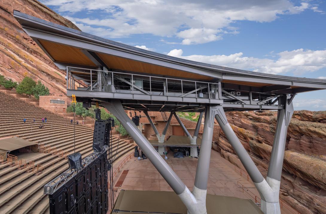
Founding the new columns presented a construction challenge as compressive and sustained tension column loads forced the use of


micropiles and pile caps, both of which needed to be installed within the low ceiling height below the stage. e columns were tucked into corners of the existing construction to avoid impeding the existing architectural layout. is resulted in pile caps ranging from 36 inches at concentrically loaded pile groups to 60 inches thick at eccentrically loaded pile groups to accommodate existing construction. 34 micropiles, with 90 kips axial service compressive capacity each, were installed to resist the new column loading.
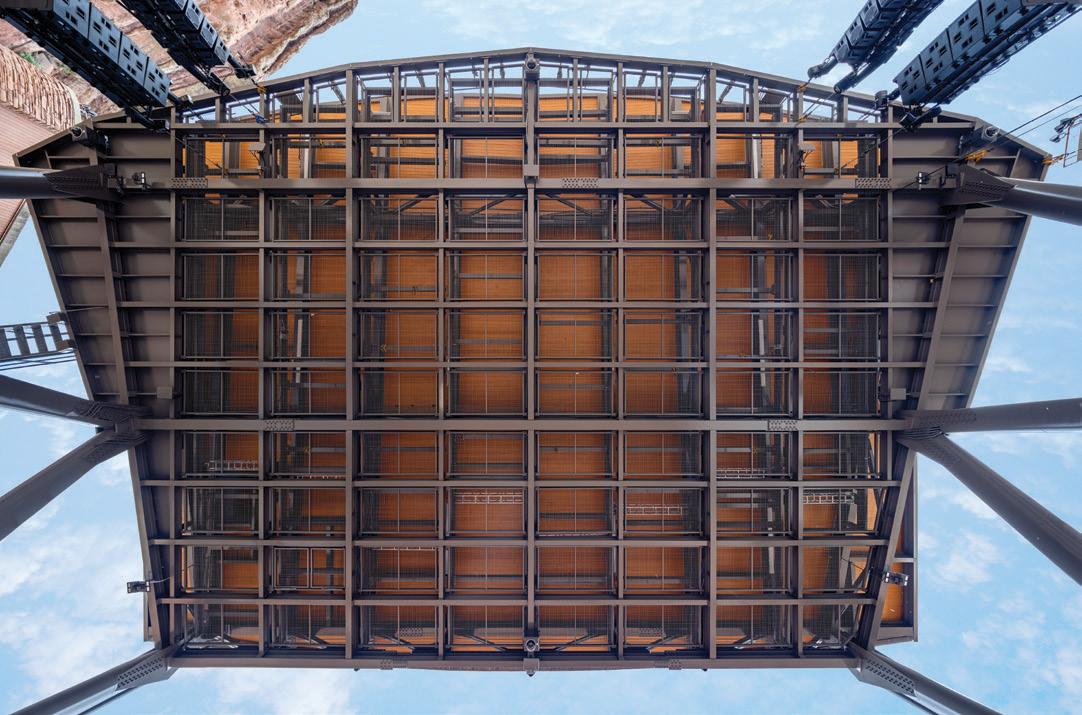
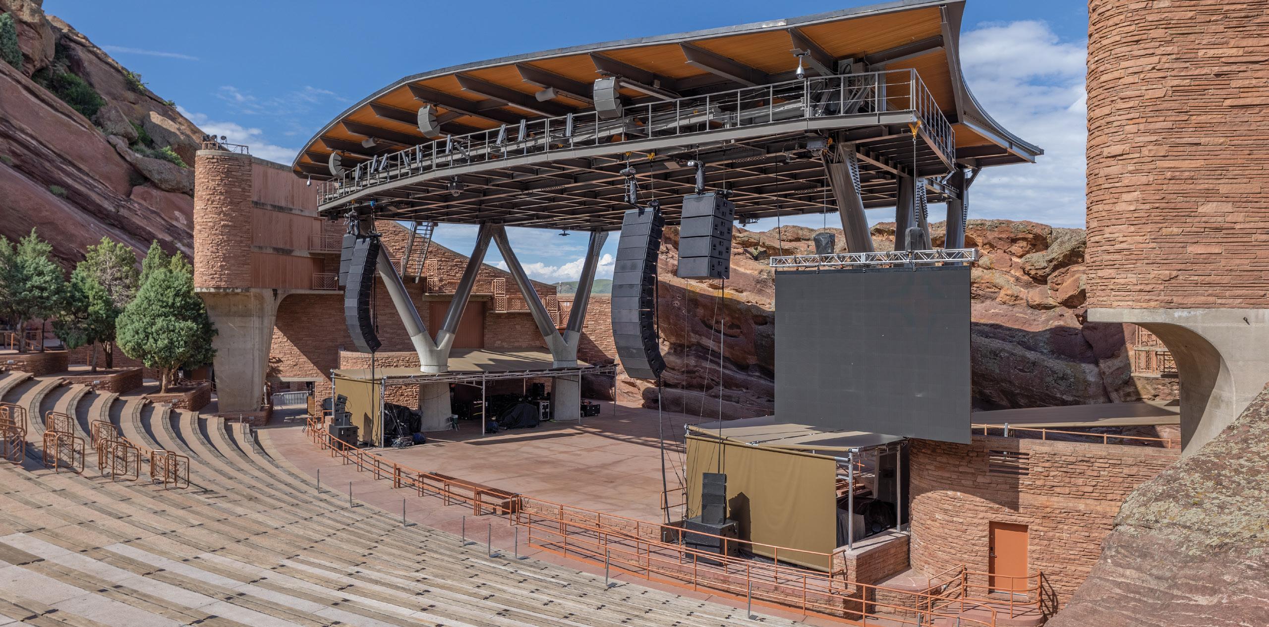
e $6 million stage roof replacement serves the City and County of Denver’s needs to accommodate modern rigging demands while providing a safe space for workers to rig the many shows the world-famous venue holds. In addition, with unobstructed sightlines, concertgoers can now view any of the performers from any location throughout this iconic venue.■
Nick Ereckson is a Principal with Martin/Martin, Inc. and leads the firm’s Sports, Entertainment, and Commercial group (nereckson@martinmartin.com).
Chris Adams is a Senior Project Engineer with Martin/Martin, Inc., specializing in Sports, Entertainment, and Commercial project types (cadams@martinmartin.com). Project Team Owner: City and County of Denver Structural Engineer-of-Record: Martin/Martin, Inc., Lakewood, CO Architect of Record: Short Elliot Hendrickson, Inc., Denver, CO General Contractor: GH Phipps Underside of roof structure from stage. Courtesy of Frank Ooms. Side view of roof structure. Courtesy of Frank Ooms.




 By Jessica Mandrick P.E., S.E., LEED AP, Karl Rubenacker, P.E., S.E., and Lizhong Wang
Cast iron columns, commonly used in building construction in the 1800s and early 1900s, possess low tensile capacities and require special attention to detail in building alterations. 315 Hudson Street is a ten-story cast iron column building undergoing such alteration in New York City. Extensive renovations to the building included lowering a portion of the ground floor structure, transferring two off-grid columns at the ground floor via transfer beams at the second floor, and reinforcing columns for new rooftop loads. Each endeavor required novel detailing to brace, support, and reinforce the cast iron columns in a manner that limited tension on the cross-section.
315 Hudson Street was originally constructed in 1896 by the Henry Heide Candy Factory, maker of Jujyfruits® and Jujubes®. e building size was doubled with a horizontal addition in 1903 and doubled again with a second horizontal addition in 1911 (Figure 1). ese original buildings framed a central yard infilled in 1962 with a new elevator core to create a unified office building after the candy factory relocated to New Brunswick, New Jersey. e 200- by 214-foot building includes 385,000 gross square feet. Jack Resnick and Sons, the owner of the commercial office space since the early 1960s, redeveloped the property into a Class A office building, with renovations completed in 2021 led by FX Collaborative Architects. e owner selected Gilsanz Murray Steficek to provide structural engineering services for this project
Figure 1. Floor plan showing construction over time and extent of new work.
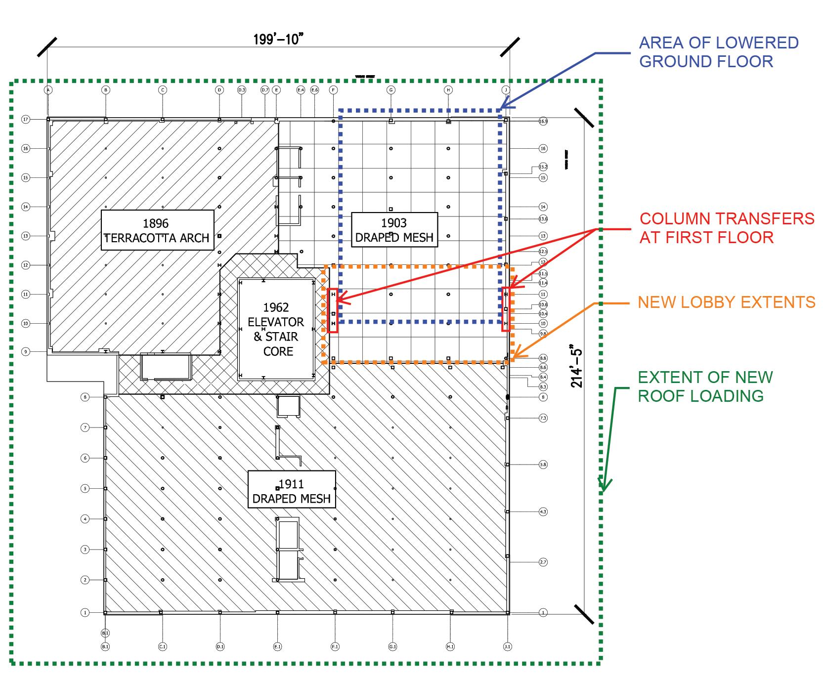
based on the firm’s experience with historic building typologies and reputation for tackling unconventional problems.

e buildings comprising 315 Hudson are composed of structural terracotta arch floors or draped mesh cinder concrete slabs, supported on steel or wrought iron beams that frame into cast iron columns. e perimeter walls and interior cores are multi-wythe brick. e floor live loads in the original construction varied from 150 to 300 psf.
Figure 2. Cast iron column capacity before and after the 1916 Code.
Calculations governing the compressive capacity of cast iron columns have been present in the New York City Building Code (NYCBC) since at least 1899. However, these early capacities for cast iron compressive strength were deemed unconservative following a series of failures, and the code capacities were decreased in 1916. A comparison of the allowable stresses before and after 1916 is shown in Figure 2. As allowable stress values decreased, many older buildings found it challenging to justify renovations and alterations that increased the load on individual columns. In renovations, cast iron columns are often replaced or supplemented by new steel columns positioned on two or more sides so as not to create unbalanced loading in the cast iron.
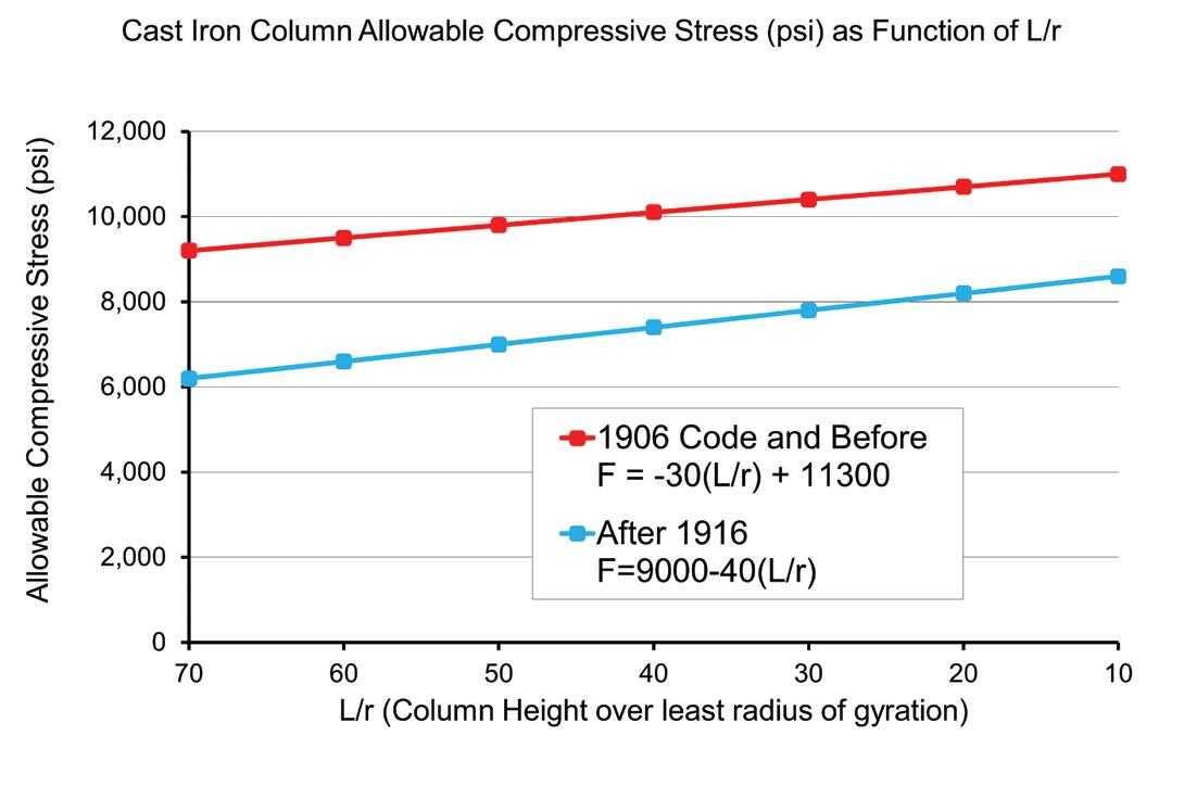
In the case of 315 Hudson, the building’s original factory live loads were reduced to live loads between 50 psf and 150 psf based on the new occupancies, and the capacity of the columns was re-evaluated under the 1916 code. The 1916 formulas are referenced in the 1938 and 1968 NYCBCs, which are utilized for existing buildings today.
The 1916 NYCBC also specifies the allowable short-column compressive capacity (16,000 psi), shear capacity (3,000 psi), and tensile capacity (3,000 psi) of cast iron. The bend ing capacity is similarly 16,000 psi on the compression side and 3,000 psi on the tension side. These values are utilized in checking local stresses at areas such as beam connections and bearing plates using an elastic analysis. Cast iron is not utilized under gross tension as it behaves brittlely, and there is no yield plateau.
Welding to cast iron is difficult due to its high carbon content, which can lead to brittleness and cracking of the weld material. As such, all connections to existing cast iron were made via drilled and tapped bolts (Figure 3). The tapped holes and bolts were typically ¾ inch in diameter or smaller and extended into the cast iron column for its full thickness. The tap and drill diameters were selected to achieve a minimum of 75% thread engagement. Where columns are round, the connection plates are curved to match the diameter of the column. The bolts to cast iron were specified as A307 grade, not high strength because A307 is more ductile, and the bearing on the cast iron column controls at the bolt interface. The Structural Engineering Association of New York (SEAoNY) has also put together resources on cast iron columns, reporting engineers satisfactorily using holes up to 1-inch-diameter at 4-inch spacing. The drawings for the 1896, 1903, and 1911 building construction are lost to time. As such, extensive probes were conducted throughout the building to verify column diameters, column wall thicknesses, column seat dimensions, framing sizes, and slab reinforcing. Due to the fire encasement on the columns, only half of the column was exposed. Therefore, a tree caliper was used to verify the column
diameter. Holes were drilled on each side of the column, and the average column thickness was determined. Per the 1916 building code, wherever the core of a cast iron column has shifted more than one-fourth of the thickness of the shell, the thickness of the metal all around is assumed equal to the thinnest part.
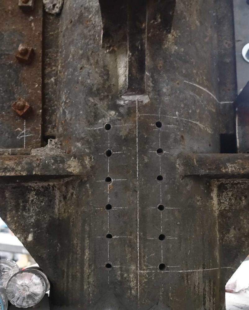

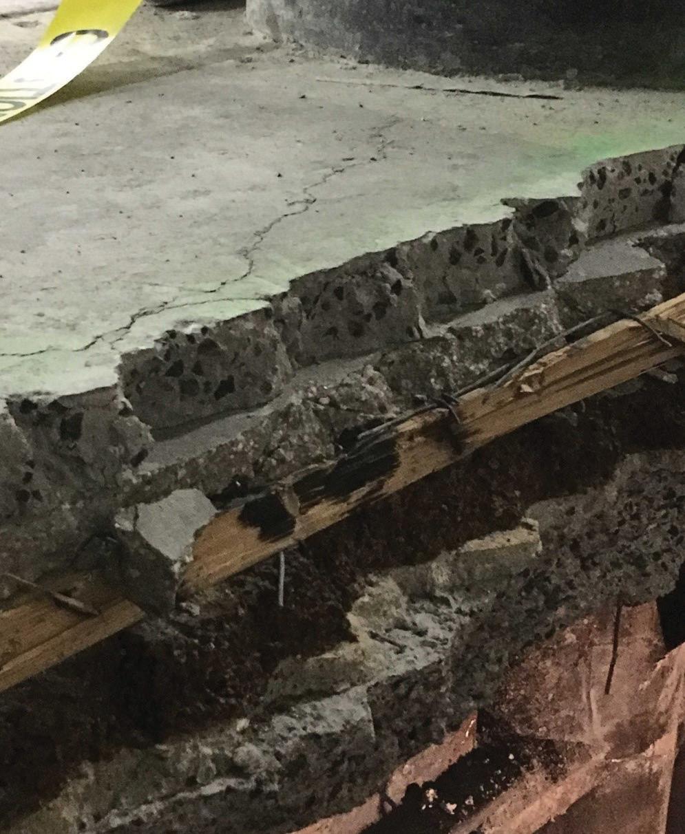
The sidewalk elevation around the building varies by approximately two feet. The building elevations of the horizontal additions gener ally match the original 1896 building floor elevations. This created a situation where much of the ground floor was elevated above the existing sidewalk and not ADA-compliant. Over time, the ground floor was subdivided into several retail spaces with different points of entry, and customers had to step up from the sidewalk into these spaces. From an accessibility and a marketing perspective, this is undesirable. The owner elected to lower the ground floor of the bulk of the 1903 horizontal addition to be level with the sidewalk on Hudson Street, creating a retail space and a lobby accessible from the sidewalk without the use of ramps. Probes revealed that finishes on the ground floor slab were layered on top of each other for over a century (Figure 4 ). This heavy build-up was removed to gain depth. However, it was still necessary to lower the structural slab and associ ated framing by approximately nine inches in the retail bays and 21 inches in the lobby bays.
Each cast iron column in this retail space supports the eight floors and a roof above and carries between 500 and 700 kips. Removing and lowering the floor slab required temporary bracing of the cast iron columns to provide stability until the new floor was in place. The initial scheme to support the cast iron consisted of direct bracing utilizing steel beams. As this option was explored further, hand calculations and finite element analysis of the column cross-section revealed that point bracing, with a pair of compressive or tensile loads on opposite faces of the columns, induced bending within the circular column cross-section that exceeded the allowable tensile stress.
The area of the lowered ground floor consists of twelve interior col umns and twenty-one bays of framing. To laterally support the columns uniformly, similar to the support provided by the slab in the existing condition, the steel bracing members terminated in steel collars filled with grout encasing the column (Figure 5 ). Where the collar was offset from the brace, the tubular steel bracing members were designed to carry the axial bracing force and the resulting eccentricity. Braces were
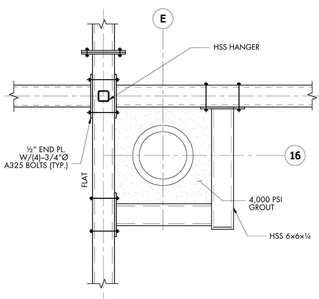
positioned below the slab, allowing unimpeded access to frame the new floor above (Figure 6 ). The braces were gravity supported to the foundations below. They sloped up at the perimeters of the opening to bear against the structural slab in the adjacent areas of the building. Nodal bracing forces considered cumulative loads from the possibility of multiple columns in a row buckling simultaneously.
The existing slab was demolished to make way for the new lowered floor. The pairs of existing 21-inch girders were removed and replaced with pairs of new composite W14s. The new girders were coped to bear or hang from the existing seats. The existing 10-inch infill beams
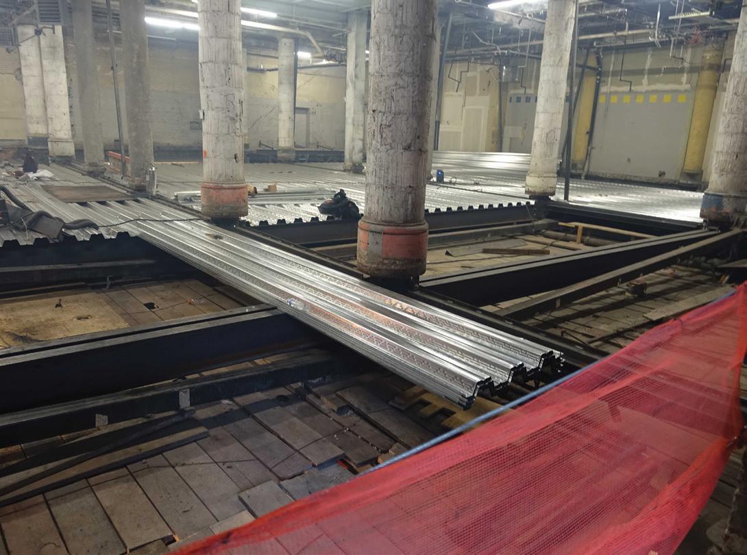
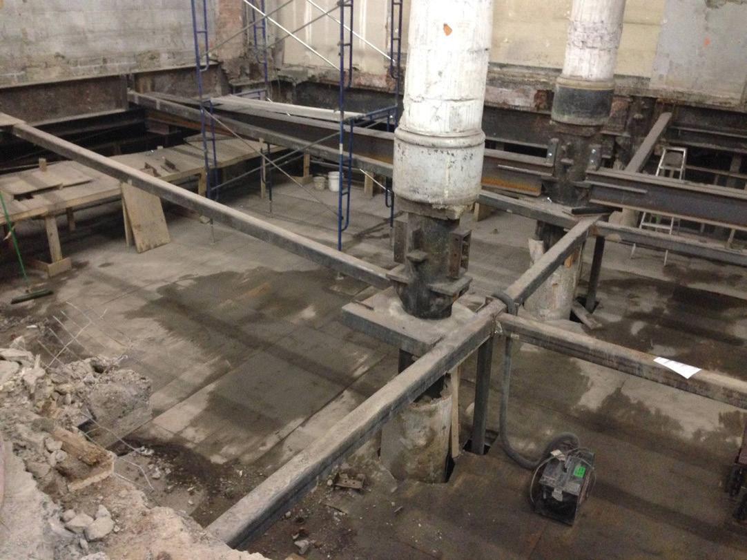
).
The renovation of the building included an enlarged three-bay-wide lobby on Hudson Street that extends back to the elevator core in the center of the building. Unfortunately, two lobby columns were off-grid and did not work aesthetically with the conceptual designs. These off-grid columns were located within the former front façade and rear courtyard walls.
A pair of wide flange columns match ing the desired gridlines was added at each column transfer location to remove these two off-grid columns at the ground floor. A transfer girder composed of a pair of 28-inch-deep by 6-inch-wide built-up channel members was designed to be bolted to the outside face of each flange of the new columns and pick up the cast iron column above. A bolster was fabricated to support the flanges of the cast iron above and taper down to the wider spacing of the transfer girders below. The contractor substituted 4-inch solid plates in place of welding the built-up channels.
The load was jacked from the exist ing second-floor column into the new steel through a permanent steel collar with up to 144 drilled and tapped bolts (Figure 8). This collar is connected to temporary jacking beams on either side of the existing column. A pair of jacks were used to transfer the existing load on the column into the new transfer beams and pre-deflect them before removing the cast iron column below (Figure 9). After the load transfer, the existing first-floor cast iron columns were removed with exothermic cut ting rods.
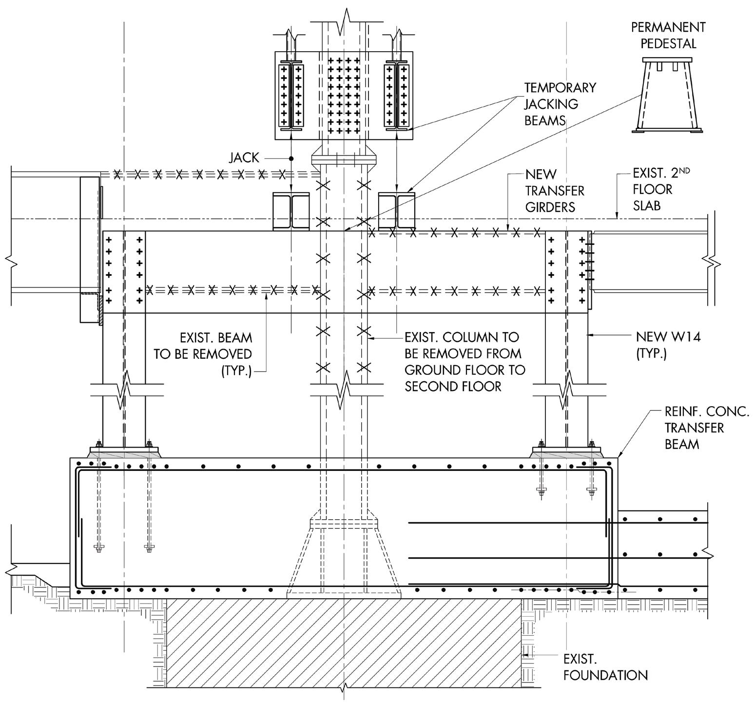
The new columns were transferred back to the existing foundation at the unoccupied subcellar level to avoid new foundations and potential settlement. This transfer was accomplished with a concrete grade beam supported on the existing footing and an outrigger to the adjacent column foundation for stability.
New mechanical systems for the building, as well as a green roof, rooftop assembly space, and roof terrace, imposed additional loads at the building’s upper levels. This led to the overstress of some columns at the top of the building when checking their capacity by the 1916 formula. Due to the high live load capacities of the original floors, and the lower live loads from the new occupancies, this overstress quickly dissipated, and the columns on the lower floors did not need to be reinforced.
The method of reinforcing consisted of steel half pipe shells with welded shear studs on the inside (Figure 10). The cast iron column was drilled and tapped with a series of A307 bolts. The half pipe shells with shear studs were joined to the cast iron column by structural grout poured into the interface. This grout bore on the cap plate of the larger column on the floor below. The reinforcing was checked in multiple ways: to provide load transfer between the shear studs and tapped bolts using the grout interface, using the added shell to brace the inner column, and passing loads through the shell/grout through bearing on the columns below. Where reinforcing was required at more than one upper floor, four steel angles were threaded between the existing beams to carry the load from one reinforcing shell to another.
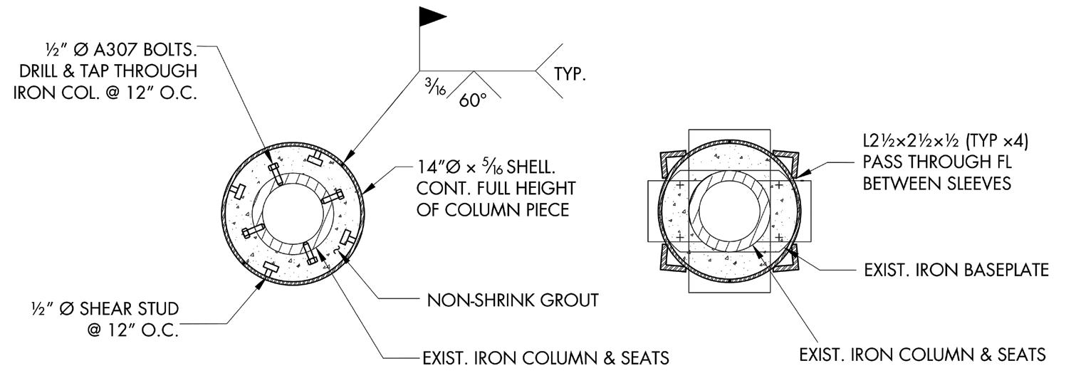
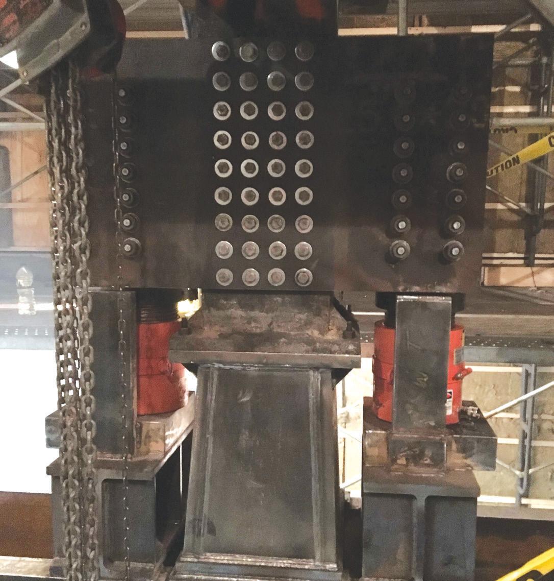
Another cause for reinforcing at the uppermost level was unbalanced loading. When the new mechanical equipment or roof deck resulted in a larger shear reaction on one side of the column than the other, this induced an eccentricity into the column. When this moment or the local shear and tensile stresses at the connection resulted in tension of more than 3 ksi in the column or seat, column and connec tion reinforcing were implemented, or strategies were undertaken to reduce the eccentricity on the column through modifying the fram ing connections. Overstressed existing connections were reinforced by new tee supports under the existing seats, which were welded to the reinforcing shells.
Where new steel columns for the rooftop assembly area, a courtyard infill, and mechanical equipment dunnages were installed on top of the existing cast iron columns, care was taken not to transfer moment from the new steel into the existing cast iron. The cast iron cap plates with their four holes were used to connect the new steel columns, but the new steel columns were coped at the base to limit the amount of moment which could be transferred and to make the connection behave more like a pin.
Historic cast iron column buildings require special attention during renovations. Care to detail, research into prior editions of building codes, experience, and knowledge-sharing among engineers can help some of these buildings sur vive and adapt for another century.■
All authors are with Gilsanz Murray Steficek in New York City (info@gmsllp.com).
Jessica Mandrick is a Partner and a STRUCTURE magazine Editorial Board member.
Karl Rubenacker is a Partner.
Lizhong Wang is a Project Engineer.
Figure 10. Reinforcing shells.
Figure 9. Jacking assembly.
Owner and Manager: Jack Resnick and Sons
Structural Engineer: Gilsanz Murray Steficek LLP Engineers and Architects

Mechanical, Electrical, Plumbing Engineer: Dagher Engineering PLLC
General Contractor – Ground Floor Retail: ZDG
Construction Management Architect – Ground Floor Retail: Specter DeSouza Architects
Steel Fabricator/Erector – Ground Floor Retail, Rooftop Mechanical: Maspeth Welding Inc.
Architect – Lobby, Rooftop, Redevelopment: FX Collaborative Architects LLP
Steel Fabricator/Erector – Lobby, Rooftop, Redevelopment: Koenig Iron Works Inc.
General Contractor – Rooftop, Redevelopment: Structure Tone
General Contractor – Lobby, Rooftop Mechanical: JRM – Construction Management LLC
Steel Fabricator/Erector – Rooftop Mechanical: FJM- Ferro
Nestled into a hillside of ponderosa pines with views of Humphrey’s Peak, the High-Performance training facility attracts top studentathletes to Northern Arizona University. DLR Group delivered a 65,000 square-foot, three-story, state-of-the-art High-Performance Center with a 10,000 square-foot weight room, sports medicine spaces, academic center, practice basketball courts, team meeting rooms, locker rooms, and a hall of fame. e facility also has an iconic team auditorium on the third level, with unobstructed views of the 12,600-foot Humphrey’s Peak and the San Francisco Range (Figure 1). e unique spaces and environment provided structural challenges and opportunities for creative design.




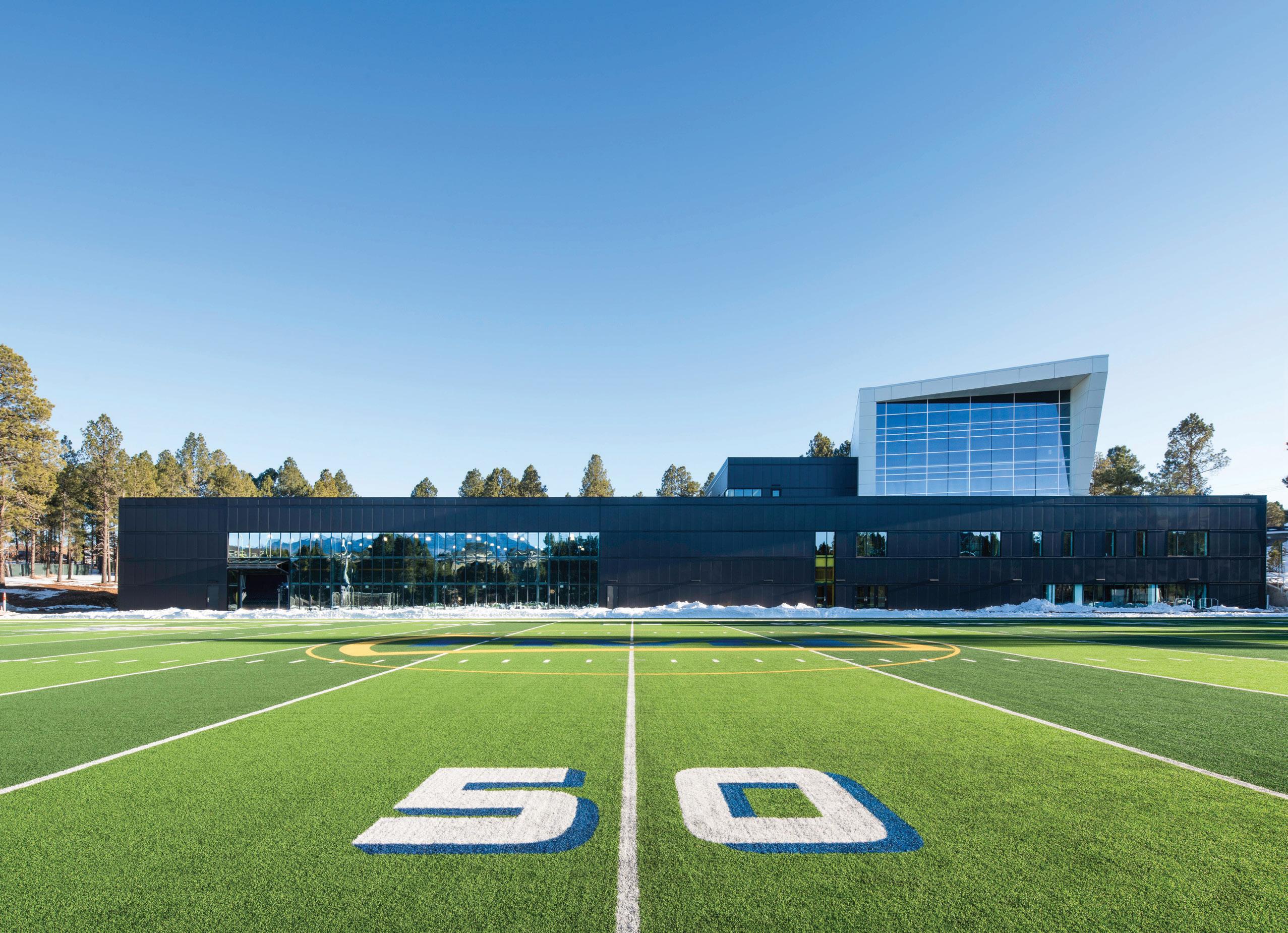




Incorporating high-performance features and honoring the environment demanded creativity in the structural design of the athletic center. For example, to achieve unobstructed views of Humphrey’s Peak, the orientation of the third-level auditorium and hall of fame, referred to as the Jewel Box, was strategically rotated 15 degrees (Figure 2). e rotation, causing geometric and cost challenges to the structure and design, required the design team to explore multiple framing options.
In its initial concept, the Jewel Box was framed as a truss, independent from the rest of the structure. e truss design, however, became expensive and cumbersome as it was challenging to coordinate the truss webs with the floor plan. e budget constraints associated with the initial truss design led to the next solution a pre-engineered metal building (PEMB). However, the Jewel Box’s extensive cantilevers and sloped geometry made the PEMB inefficient.
e Jewel Box was ultimately framed with conventional steel (Figure 3), and the team achieved cost savings in the project by having the gym and the weight room constructed as a PEMB. is hybrid framing system worked creatively to deliver on the program requirements and the unique, high-performance spaces within the athletic center. An innovative hybrid of PEMB and conventional framing provided a world-class design in a manner that delivered on budget but did not compromise the overall architectural design and high-performance needs (Figure 4, page 36 ). In addition, the creative use of the exterior paneling and curtain walls ensured building continuity, elevated these otherwise conventional systems, and provided a cohesive look and design.

e Jewel Box’s six columns punctured programming spaces on various levels below, requiring extensive coordination. One of the most critical column locations occurred in the hydrotherapy room. e


Many things make this building unique, such as its location on a hillside, its Jewel Box rotated to maximize views, and the pedestrian entrance to the third level.

hydrotherapy room houses pools on the first level, with a basement level to store all the pool equipment. e basement for the hydrotherapy room was structurally framed with 10.5-foot-tall retaining walls and 18-foot-wide footings. e Jewel Box columns extended from the third floor down to the first floor, where they were supported on 24-inch-square concrete piers that extended down to the same footing elevation as the retaining walls. e Jewel Box’s steel columns had to be strategically positioned to avoid the retaining walls.


e collaboration of all structural systems, delegated systems, architectural and mechanical needs, program requirements, and exterior systems created complexities and unique problems in all design phases. As the structural engineer of record, DLR Group managed connections, deflection requirements, and loading between many parties while providing a cohesive design.
e success was largely attributed to an amplified focus on performance criteria. An example of this can be seen in the connections of the wall paneling system. e structural team coordinated the expected 0.07-inch deflection of the 12-foot cantilevered retaining walls with the connection requirements of the 2½-inch insulated wall panels and the expected ¾-inch drift of the steel building superstructure.


e steel columns were placed 1 inch from the retaining wall, and custom wind girt connections were designed for the metal wall panels. HSS wind girts were placed at 8-foot vertical increments – coinciding with the height of the insulated metal wall panels. e custom connection from the HSS wind girts to the panels resulted in an easy installation anchor point for the contractor. e connection of these different systems, each designed by different parties under the guidance of the structural team, created an urgent need for constant communication to anticipate and resolve any constructability issues and ensure the performance criteria were met (Figure 5, page 36 ).





e pedestrian bridge entry to the third level celebrates the landscape while giving visitors a dramatic approach through the pines as they enter. It also promotes ingenuity of design for efficient use of materials and labor. Located on a hillside, the Student Athlete High-Performance Center has its north side adjacent to the existing football practice field and its south side against the hillside. e university required access to the third-level Jewel Box from the south side of the building.
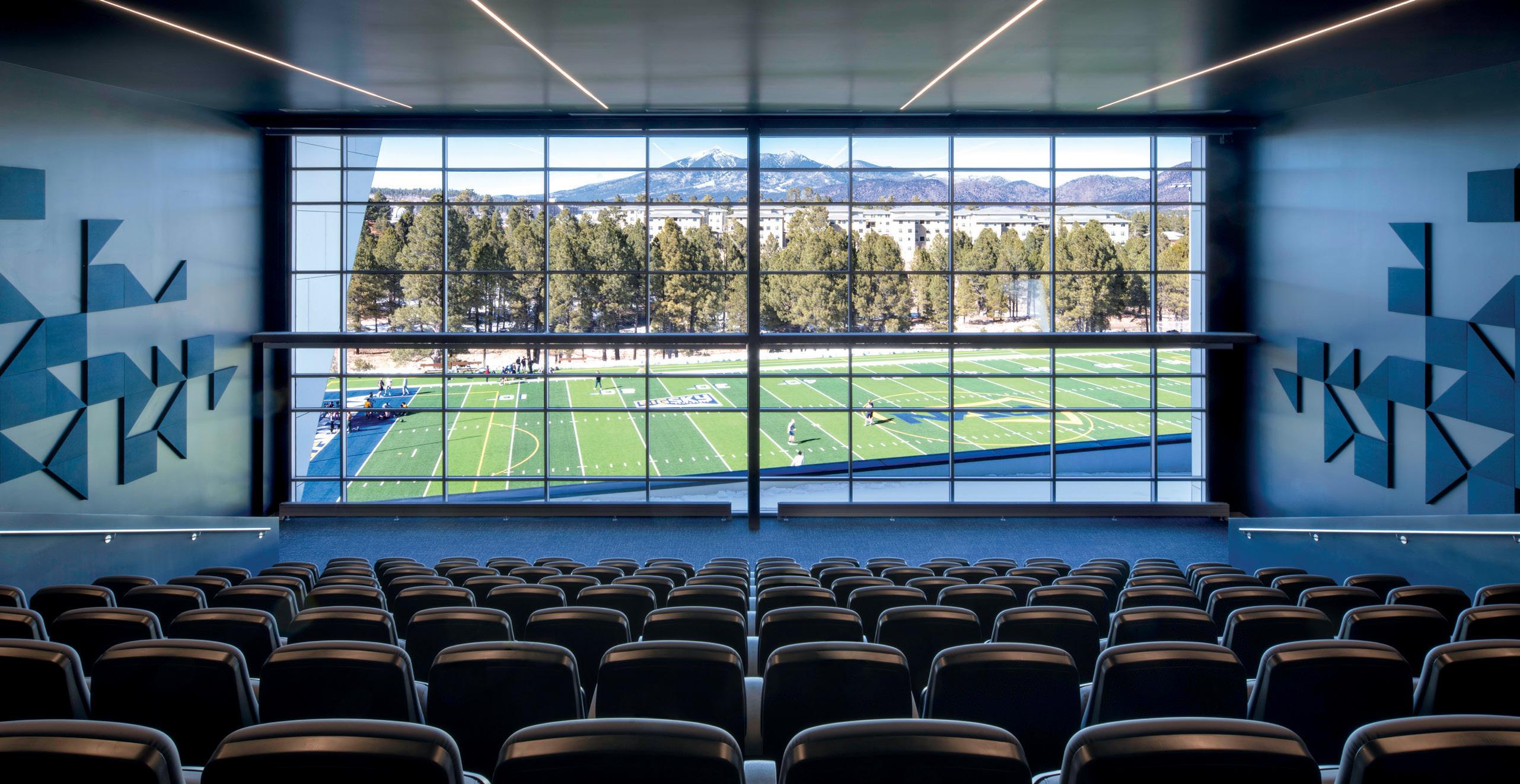
e exiting grades at the south side of the building did not coincide with the required finish floor elevation, so the team first explored
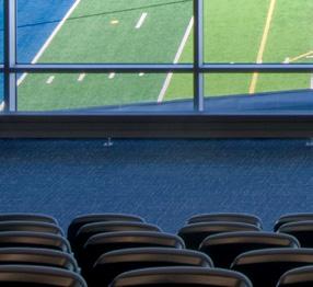 Figure 3. The structural design team explored various framing options for the Jewel Box, including a truss system and PEMB framing.
Figure 2. Skewed Jewel Box framing with offset gridlines draws attention to the mountains.
Figure 4. An innovative hybrid of PEMB and conventional framing delivered a world-class design.

backfilling the soil. However, raising the grade on the south side had other detrimental consequences, including 30-foot-tall retaining walls, large amounts of fill import, loss of daylight into the second floor, and the removal of mature ponderosa pines. erefore, the structural team worked with the topography instead of against it and provided a precast concrete bridge to alleviate and solve all these problems.
Using the 138-foot-long pedestrian bridge as a design solution provided massive cost savings and schedule benefits (Figure 6 ). e
retaining wall height was reduced to 15 feet, leaving the existing grade vastly undisturbed, gaining daylight at the second floor, and keeping the mature ponderosas in place. Furthermore, a precast patio, benches, and donor monument signs were added to the 20-foot-wide pedestrian bridge, promoting a mall concept where athletes, faculty, and staff could gather before an event. Originally a challenge, access to the third floor has now become a design feature that allows visitors to walk through the trees as they approach the building (Figure 7 ).


e interaction of the topography and bridge foundations required creative design and quick solutions even after construction had begun, as the bridge foundations interfered with several of the existing ponderosa pines integral to the building’s entrance. e bridge’s 36-inch round columns are designed to be supported by 9-foot by 9-foot by 2-foot concrete spread footings. During construction, it was discovered that the designed footing intruded on a few existing ponderosa pines. e contractor immediately requested a redesign of the footing to allow the existing pines to remain since those pines were strategic to the design concept of entering the building through the pines. e structural team quickly reviewed the foundations for new locations with eccentric loading and provided new designs during construction.
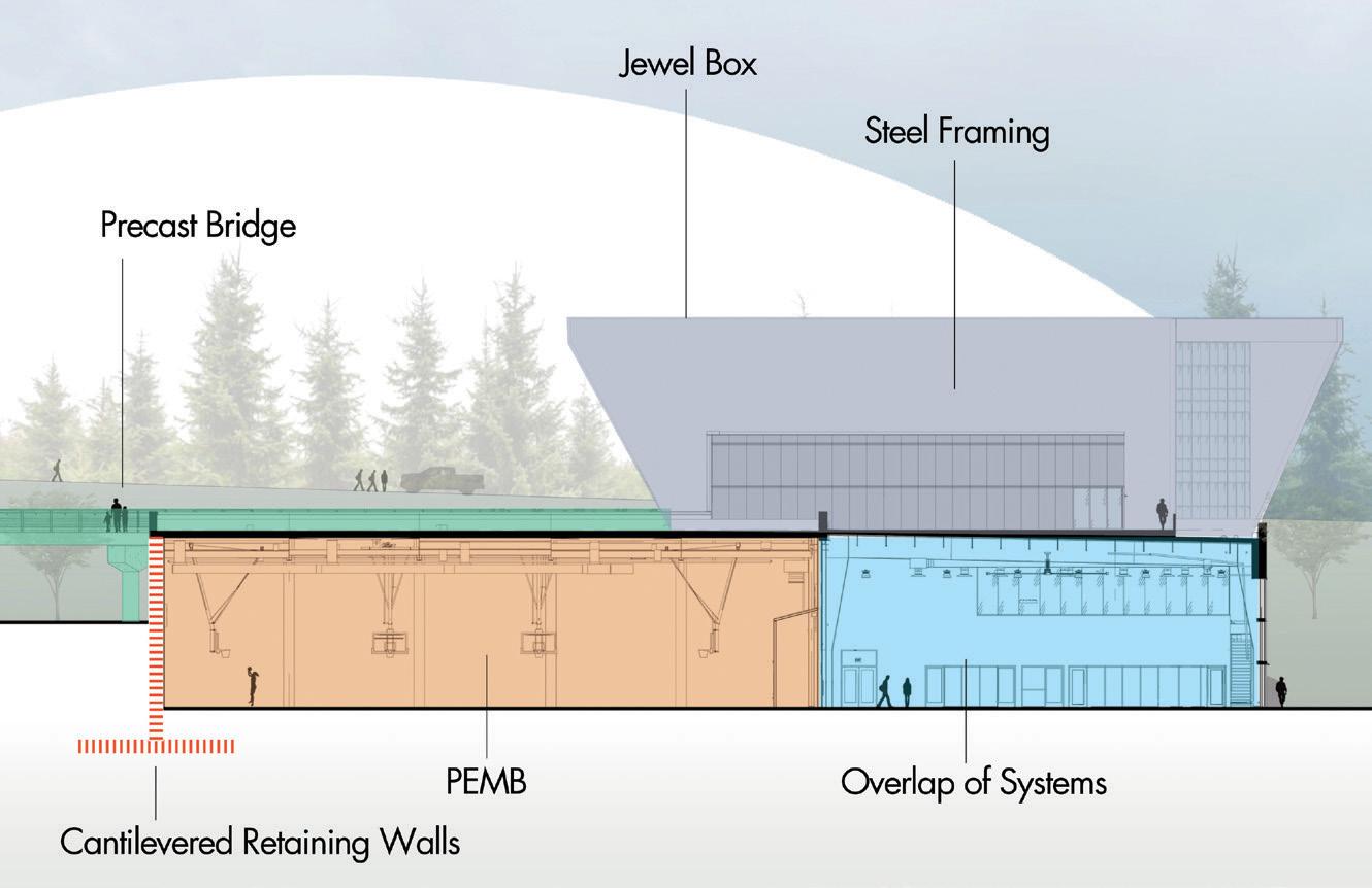
To combat Flagstaff’s cold and snowy winters, the contractor requested an early foundation package to pour before the frost set in, creating design and constructability challenges. e structural team designed foundations without completing the design of the structure, while external designers completed the steel and PEMB design. us, loading and layouts could not be guaranteed, which heightened the design challenges.
Addressing these concerns, the structural team worked with the architects to lock down grid locations and loading early. e team increased all initial reactions by 20% and limited foundations to a 50% design/capacity ratio. e resulting combination of these two strategies led to minimal changes to the foundations during construction once the final reactions were computed and backchecked against the existing footing design. Any changes that did occur during construction were more efficiently managed and overcome due to this foresight.
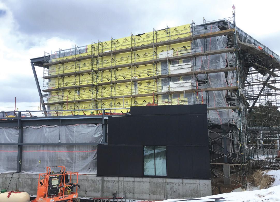


Northern Arizona University’s Student Athlete High-Performance Center showcases structural engineering excellence. Many things make this building unique, such as its location on a hillside, its Jewel Box rotated to maximize views, and the pedestrian entrance to the third level. As a result of these challenges, the engineering team had to perform at higher altitudes to design solutions on budget, use materials efficiently, and overcome construction challenges.■
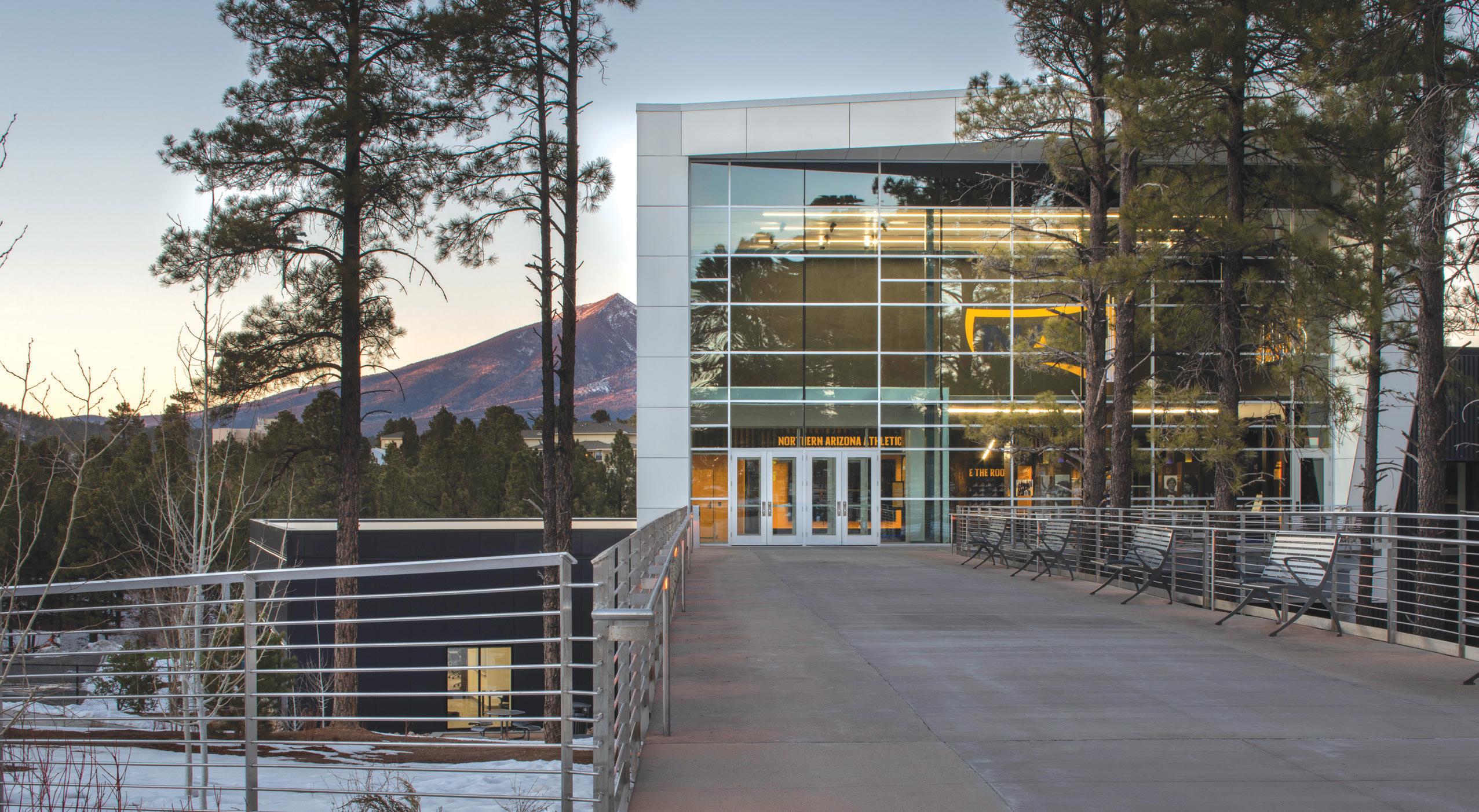
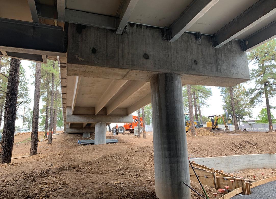
The author would like to thank Mark Forman, DLR Group, who was the Structural Engineer of Record of the project and Stanley L. Axthem, DLR Group, who was the Architect of Record.
Diana Gonzalez is a Project Engineer with the DLR Group in Phoenix, AZ (dgonzalez@dlrgroup.com).




 Figure 7. The structural team implemented design strategies that led to minimal foundation changes during construction.
Figure 5. The structural team coordinated multiple systems and unique deflections while maintaining a cohesive design.
Figure 6. Bridge connected pedestrians to nature while reducing cost and preserving trees.
How do you build a 19-story, 305-foot-tall tower with 25-foot cantilever volumes offsetting in a counter-clockwise arrangement every two to three stories around the perimeter? Early discussions with Boston University, the design team of KPMB Architects, structural engineering firms Entuitive and LeMessurier, and construction manager Suffolk Construction identified the means and methods of erection as critical to the success of the Boston University’s Center for Computing & Data Sciences Building. Design-Assist, starting after the submission of Schematic Design, was utilized to identify the temporary erection procedures required to construct the tower. Steel fabricator, Canatal Industries, erector Prime Steel Erecting, and their engineer Simon Design Engineering were engaged to partner in the Design-Assist process with the design team.
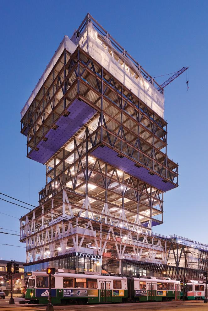
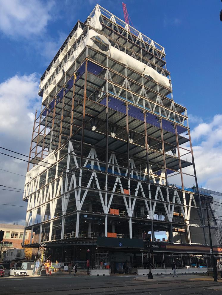
In contrast to the traditional Design-Bid-Build, the Design-Assist delivery method engages the construc tion team to collaborate with the design team during the design development. The process encourages input from the construction team during the design phase. The goal of Design-Assist is to add value to the project by making informed decisions to identify constraints, improve constructability, reduce cost, and better define the construction schedule. A series of remote and inperson workshops were held on the Boston University project to facilitate the Design-Assist process. The teambuilding workshops allowed for discussion of critical

and erection, the associated impact on the base-building structure, and cost and schedule impacts. Due to the constrained site, many shoring options were pursued to simplify construction and meet the project schedule, including impact on subsequent trades.
The ANSI/AISC 303, Code of Standard Practice for Steel Buildings and Bridges, notes, “The structural steel specifications shall include any special requirements for the fabrication and erection of the struc tural steel.” In addition, “The owner’s designated representative for design shall identify the following in the contract documents: a) The lateral-load-resisting system and connection diaphragm elements that provide for lateral strength and stability in the completed structure; and b) Any special erection conditions or other considerations that are required by the design concept, such as the use of shores, jacks or loads that must be adjusted as erection progresses to set or maintain camber, positions with specified tolerances or prestress.” Also, “Based upon the information provided”… “the erector shall determine, furnish and install all temporary supports, such as temporary guys, beams, falsework, cribbing or other elements required for the erection process.” For a more conventional building, the design and means and methods for erection have minimal impact on the base structure in the final condition. However, it was clear that given the structure’s complexity and three-dimensional nature, this process was not linear, and decisions by the construction team would impact the design of the base building structure and vice versa.
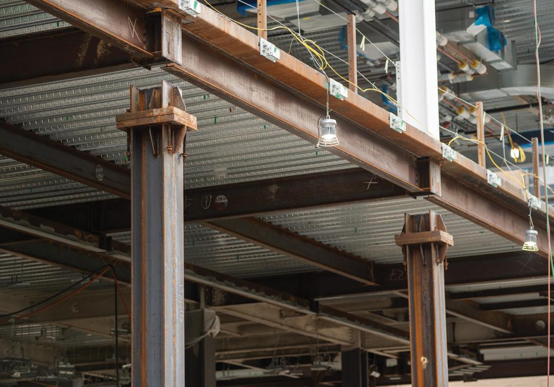
The primary structure consists of two-story-deep trusses made of wide flange steel and located along the perimeter of the building. Single-span trusses run the entire building length and are supported by a truss in the perpendicular direction at each end that cantilevers a single bay. Given the offset building massing and location of trusses, portions of the building are supported from below while other floors are hung from framing above. The concrete floor diaphragms attached to the concrete core provide lateral bracing of truss compression chords. This required all concrete floors at truss levels to be placed and reach strength prior to shoring removal. The steel framing and concrete floors were superelevated for 80 percent of the calculated
dead load deflections. Steel columns and bracing was intumescent painted, AESS category 1, with exposed and polished concrete floors.
Per ANSI/AISC 303, the erector is responsible for “the means, methods, and safety of erection.” At the same time, the structural engineer of record is “responsible for the structural adequacy of design in the completed condition.” Temporary shoring by the steel erector is typically not designed for the weight of concrete. Shoring is commonly provided to a predetermined level to allow steel erection when the shoring is removed. Given the constraints of the structural system and the requirement to engage the concrete slab diaphragms for truss stability, temporary shoring was designed for steel erection, weight of concrete, and construction live loads.
A total of 29 building columns do not extend to terra firma, requiring temporary support for construction. Full height shoring was provided to allow for erection of the steel and placement of concrete floors. Shoring consisted of wide flange columns extending between building cantilever volumes and extending to the structure below. Wide flange “beams” were provided between the temporary columns on alternating floors to brace the shoring back to the main building. These levels were decked with a 3-inch roof deck to serve as a working platform. Cable bracing was provided between shoring columns to provide stability for shoring columns in the other direction. The steel fabrication model included both the base-building steel for the building and temporary shoring and bracing. The temporary structure was designed for the
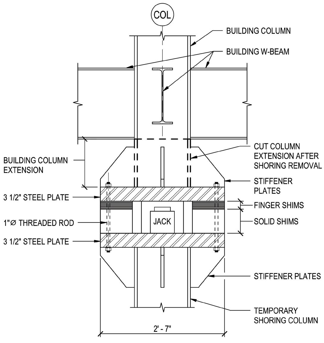
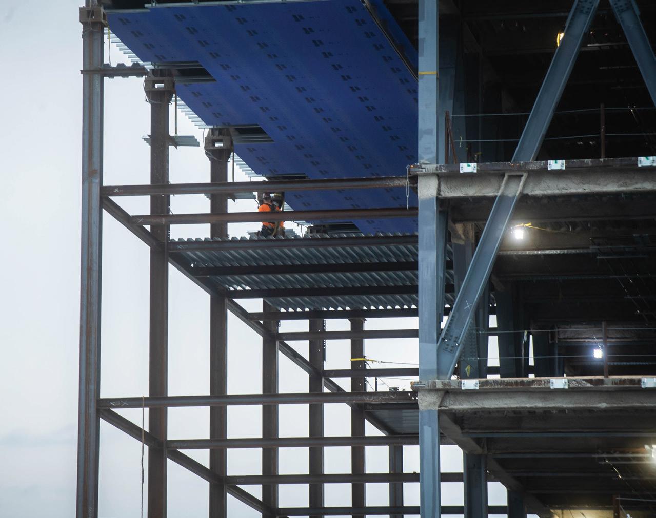
anticipated dead-load of the structure and a 20-psf construction live load. Shoring column splices were coordinated to align with building column splicing to expedite the schedule and simplify steel erection. The complexity of the structure and the need to limit deflections to allow for curtainwall installation drove the team to consider multiple approaches and construction sequences.
Jack boxes were designed into the top of shoring columns and bottom of building columns to allow for steel erection and shoring unloading. Careful consideration and detailing was required with a combination of cable stays and post-shore struts to ensure the stability of shoring columns at jack box locations during shoring unloading when the jack-box bolts were removed to allow for building move ment. Stub column sections, part of the building columns at the top of jack boxes, were cut off after jacking.
Given the shoring scheme and sequence, the base building struc ture was designed for both the final and temporary conditions. Lower columns and hangers were designed for the additional axial loads result ing from upper temporary shoring. In addition, the lower framing and trusses were designed to act as a platform where lower shores could be removed prior to completing the upper trusses. This was done at the request of the contractor to allow for flexibility in construction sequencing. Superstructure elevations were carefully coordinated with the final determined erection, slab place ment, and shoring removal sequencing.
The north and northeast corner of the tower cantilevers over the back ally adjacent to historic brownstone row housing, meaning there is no struc ture and foundation below to support
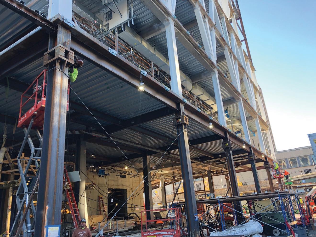
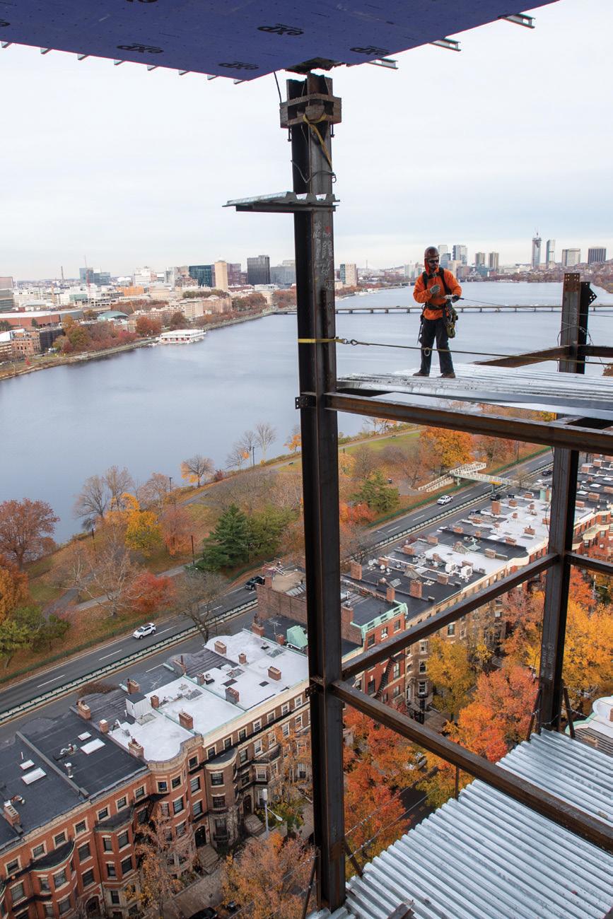
the temporary shoring columns. Options evaluated in Design-Assist included temporary foundation elements, cantilever temporary shoring, or sloping temporary shoring columns to engage the mat-slab foundation. Temporary foundation elements consist ing of multiple 100-ton H-piles with pile caps at each column were provided to simplify the shoring and erection. Deep foundation elements were required compared to shallow spread footings or cribbing, given the magnitude of the load and the requirement to limit differential settlement between the building supported by a mat slab 40 feet below grade and the temporary shoring columns. In addition, the large number of geothermal wells were installed before building construction. Careful coordination with geo thermal well locations and the installation tolerance of the wells and H-piles was required to ensure that the wells were not damaged. Grade beams spanning up to 20 feet to pile-supported caps were required at some temporary shoring locations to minimize the risk of damaging geothermal wells.
Three tower columns located over the 5-story podium did not have associated building columns or sufficient building structure directly below to allow for support of shoring columns. Therefore, temporary dunnage framing consisting of W27 framing located at the lower level was provided to transfer loads to concrete foundation walls and the mat foundations.
Hydraulic jacks were used to gradually transfer load from the tem porary shoring to the building framing and not impose dynamic loads on the base building structure. Given the three-dimensional nature of the structure and the desire not to add additional load to elements beyond their design load, all 27 tower columns would be unloaded at once. Depending on load, the load was transferred from the temporary shoring to the final building structure with 100 to 400-ton hydraulic jacks. This occurred simultaneously at 27 columns with 11 separate pumps, each manifolded to control multiple jacks. The jacking occurred at 4 floors due to the 3-D nature of the structure and location of shoring to building column transition. Loading was performed in 10% increments of the estimated self-weight of the supported structure. Calculated column unloading ranging from 100 to 700 kips depended on column location. Building elevations at each jack location were surveyed before and after jacking, with relative deflections at jack boxes monitored during unload ing. Steel shims included in the jack box assembly were incrementally removed as the shoring was unloaded and the build ing deflected.
It was important with the Design Assist process to define clear roles and responsi bilities regarding the design of temporary conditions during construction. The construction team was responsible for designing and documenting the temporary shoring and bracing and selecting jacks for unloading and detailing the associated jack
boxes. In addition, at the request of Suffolk and approval of Boston University, the design team took on responsibility for the evaluation of temporary shoring loads (provided by the construction team) on the partially completed structure and design of temporary pile-supported foundations where shoring did not extend to terra firma.
The Design-Assist process included teamwork between the design and construction teams to make informed decisions on the building design beyond the temporary conditions during construction. The process allowed for early coordination with other trade partners, such as curtainwall, which also was engaged in Design-Assist. The process allowed for refinement of column splice details, beam connections, deck and connections to the concrete core, column splice locations, and evaluation of typical project details. Details were evaluated for cost and schedule with the design team, owner, detailer, fabricator, and erector as active participants.
The cantilevered structure of the building supported by the perimeter steel truss framing is an integral part of the architectural language. The structural steel framing is exposed to tell the story of the building. The Design-Assist process allowed an in-depth review of the architectur ally exposed steel elements. Significant attention was afforded to the most prominently exposed connections. Representative truss connections were designed and detailed early in Design-Assist, with options presented as preliminary detailed shop draw ings and “ifc” files for review. Connections were evaluated for cost, schedule impact, erectabilty, and visual appearance. Two full-scale mockups, one bolted and one welded, were constructed for review. The process allowed for the refine ment of an all-field-bolted truss connection that was visually acceptable and supported the project budget and construction schedule. The Design-Assist process allowed for rigorous input to the design and appearance of the bolted connections. This included developing a set of hierarchical rules for the orientation of bolt heads, head types, etc., that were guided by which faces of the connections were most exposed to view. In the opposite sense, the process allowed influence from the architectural team to conceal steel truss connections in areas where their appearance was less desirable. Subtle moves were made to connections where connections were raised above ceilings or lowered to be concealed by the structural slab to fit with the building.
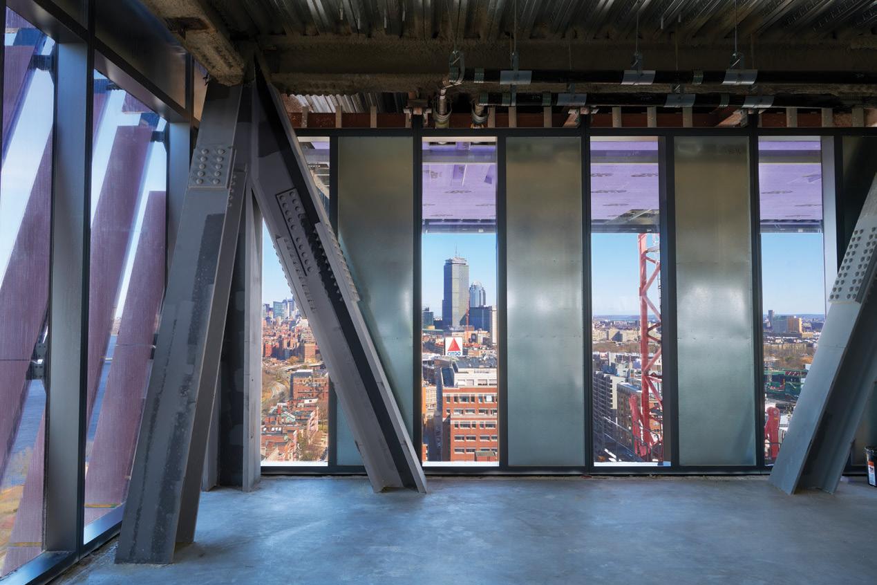
The Design-Assist process is a collaborative and team-focused approach to design and construction. The development of the structural steel design through Design-Assist for the Center for Computing & Data Sciences was a highly collaborative and occasionally social pursuit that helped build trust and
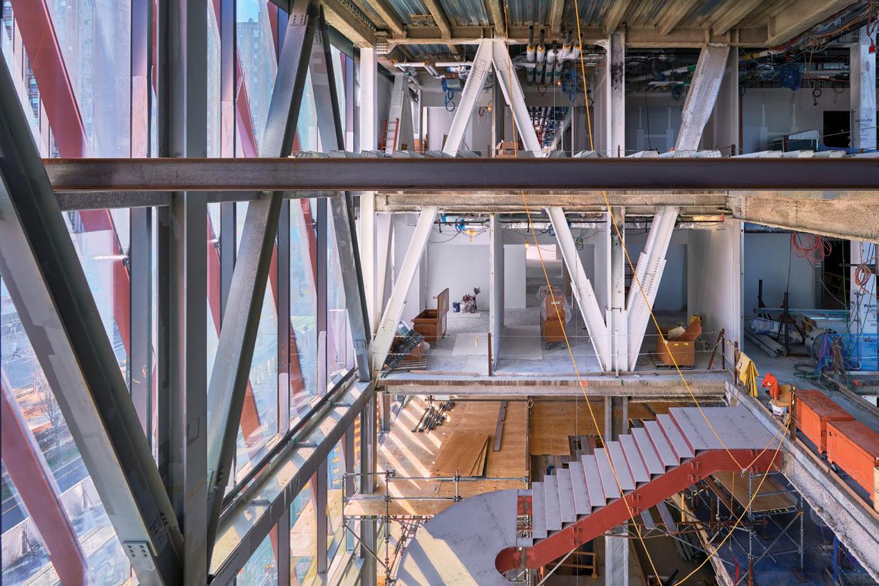
confidence between the parties involved to benefit the project. The partnership was established very early in the design, and the team main tained an open dialogue throughout the design process. A consistent feedback loop that considered all aspects of the design, architecture, constructability, budget, and schedule was the foundation of the team’s approach. This collaboration and team-first mental ity were the keys to making this project a success.
■
See STRUCTURE’s January and June 2022 issues for additional articles on the Boston University Center for Computing & Data Sciences.

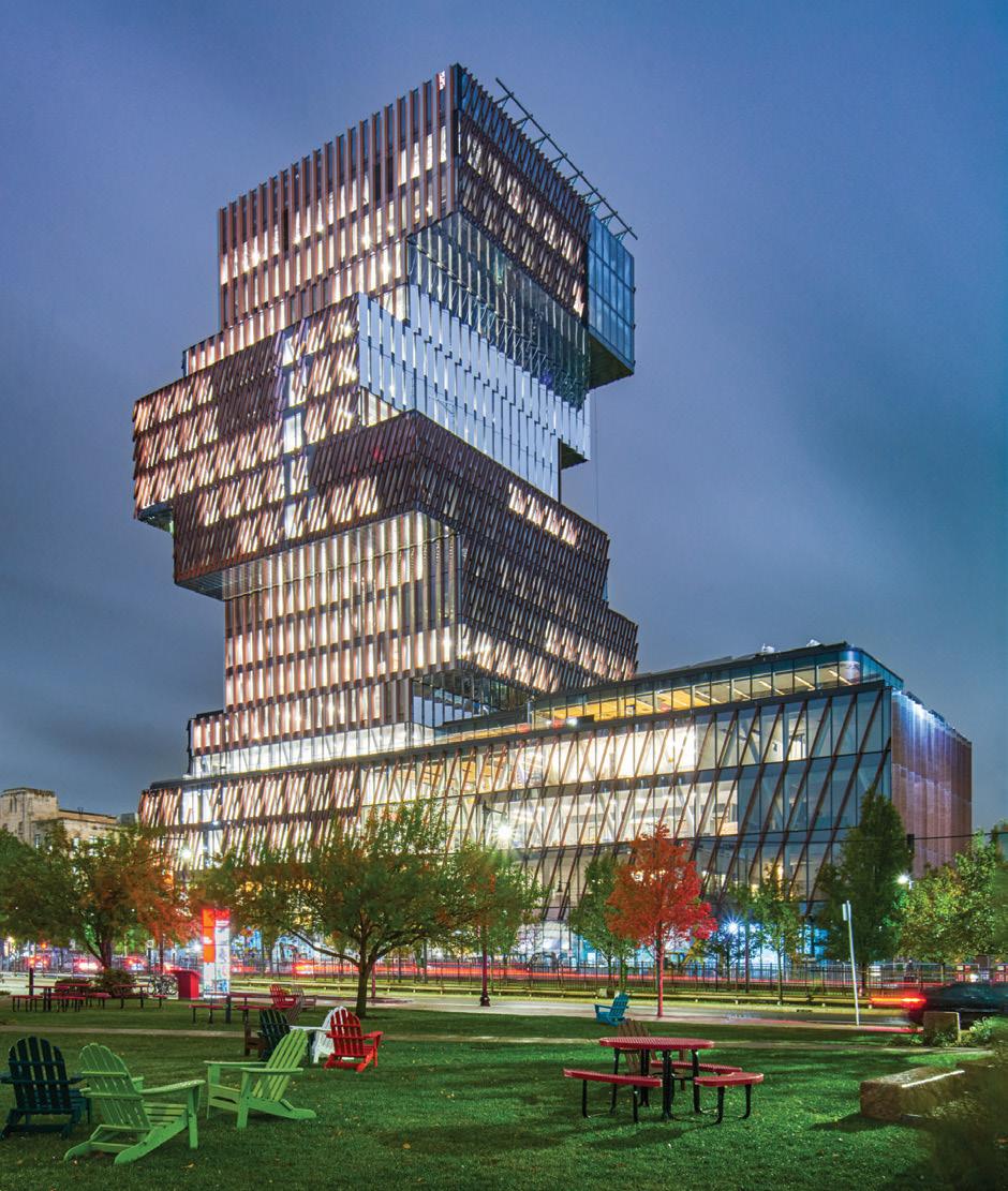
Nathan Roy is a Principal with LeMessurier (nroy@lemessurier.com).
Jamie Hamelin is a Senior Associate with Entuitive and is based in its Toronto, Canada office (jamie.hamelin@entuitive.com).
Dave Smythe is a Senior Associate with KPMB (dsmythe@kpmbarchitects.com).
Alan Simon is a Principal and Owner of Simon Design Engineering (asimon@sde-us.com).
Specify cladding and curtain-wall connections with the new Edge-Tie™ system from Simpson Strong-Tie. Designed with a unique, extruded shape and pour stop, it provides two times the load capacity of traditional bent plates. This innovative solution utilizes bolts that allow installers to easily position and adjust anchors along a continuous slot. By eliminating field welding, the Edge-Tie system speeds up building enclosure while saving time and labor costs. It’s simply a smarter, faster way to get the job done.
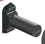
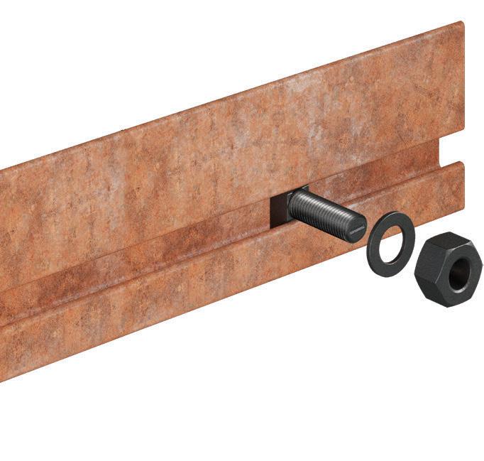
Engineer your next project with all of our structural steel solutions. To learn more, visit go.strongtie.com/edg etiesystem or call (800) 999-50 99.
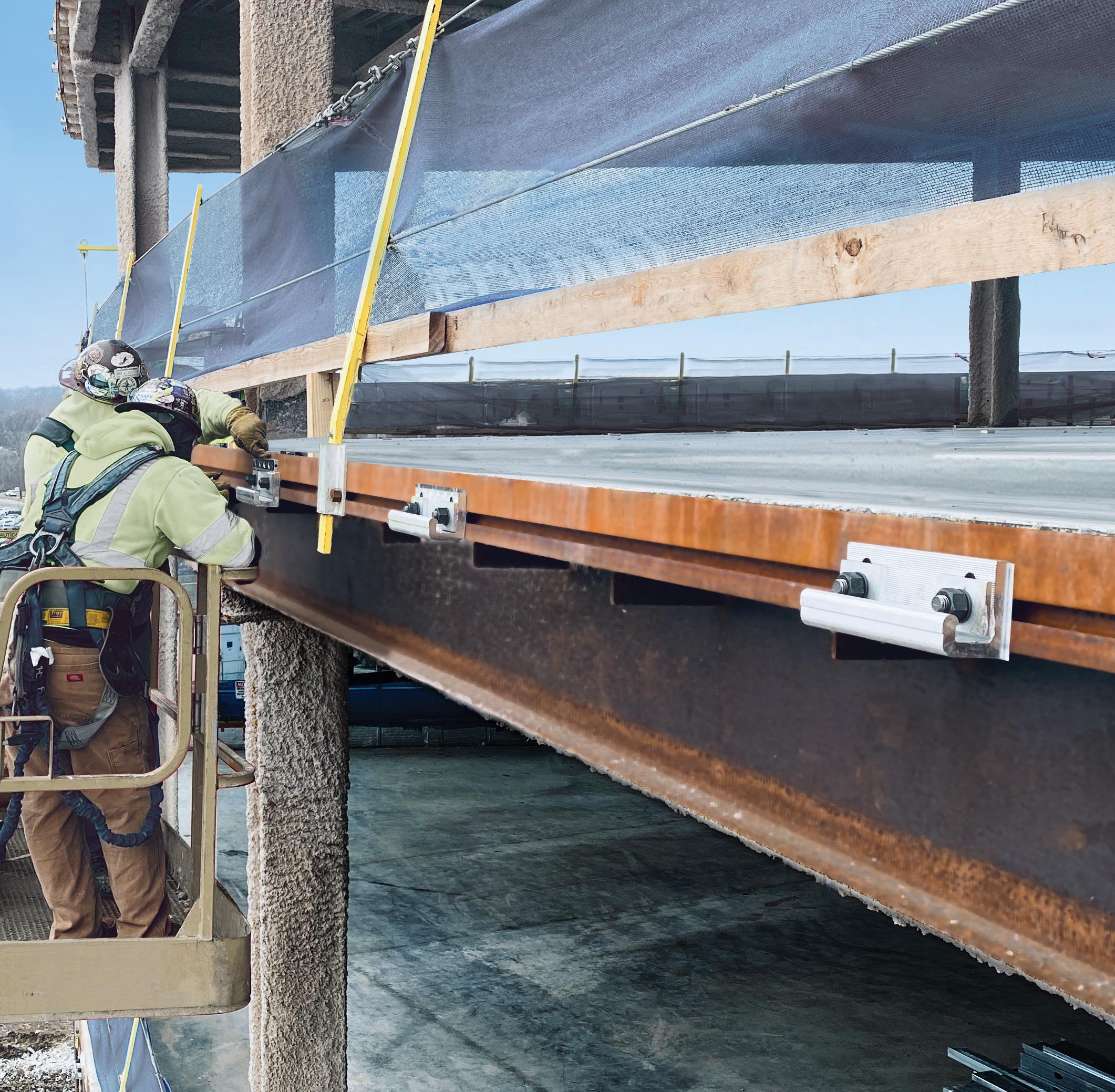
Using wood structural panels that are required to resist lateral loads and normal wind load requirements of the IBC Section 1609.6.4.4.1, Chapter 30 of ASCE-7, or IRC Section R301.2.1, additional wind uplift resistance from the panel can be achieved by providing addi tional nails to the shear nailing at the top and bottom of the panel. These additional nails are used to transfer the uplift forces from the top plate to the panel, from panel to panel at splice locations (if present), and from panel to sill plate at the foundation, effectively eliminating the need for uplift straps at these locations. Uplift straps may still be required around window and door openings in exterior walls to transfer the wind uplift loads acting on the header to the foundation below.
Basis of the APA System Report SR-101
• 2015, 2012, and 2009 International Building Code: Sections 104.11, Alternative materials, design and methods of construc tion and equipment, and 1604.4, Analysis
• 2015, 2012, and 2009 International Residential Code: Sections R104.11, Alternative materials, design and methods of construction and equipment, and R301.1.3, Engineered design
• 2015 ANSI/AWC National Design Specification for Wood Construction (NDS)
• 2010 ASCE/SEI 7-10 Minimum Design Loads for Buildings and Other Structures
• 2015 ANSI/AWC Special Design Provisions for Wind and Seismic (SDPWS)
• 2015 ANSI/AWC Wood Frame Construction Manual (WFCM)
• APA Test Reports, Combined Shear and Uplift Tests on 7⁄16 -inch Oriented Strand Board Panels, Combined Shear and Wind Uplift Tests with 10d Common Nails, and Development of Anchor Bolt Spacings for Combined Shear and Uplift Applications
Wood structural panel sheathing or siding shall be permitted to simultaneously resist shear and wind uplift loads provided the fol lowing conditions are met:
• Panels shall have a minimum thick ness of 7/16 Performance Category and may be installed with the strength axis parallel or perpendicu lar to the studs,
• Anchor bolt spacing shall be in accordance with Table 1 (online), depending on the magnitude of shear and uplift forces,
• 3- × 3- × 0.229-inch steel plate washers shall be used at anchor bolt locations,
• Nails in any single row shall not be spaced closer than 3 inches on center, and
• Nails in any double rows shall be spaced ½ inch between rows.
• Framing anchors and uplift straps that form all parts of the wind uplift resistance system shall be attached to framing on the wood structural panel sheathing side of the exterior walls.
The above conditions effectively elimi nate the cross-grain bending as a failure mode in the bottom plate, as shown by full-scale test results. Assuming conditions are met, the following steps may be used to design wood structural panel sheathing or siding to simultaneously resist shear and wind uplift loads.
Figure 1. Panel attachment for shear and uplift. continued on next page
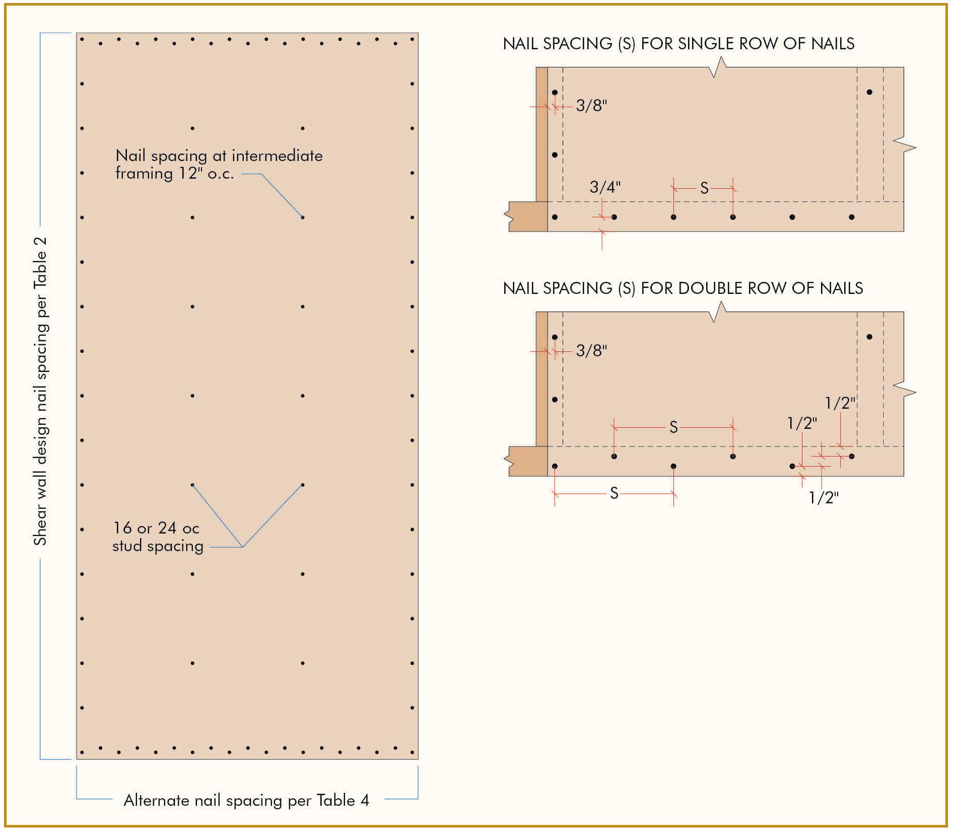
The first step in designing for combined shear and wind uplift is to design the shear walls for the structure under the applied wind loads. This method may be used for either the conventional seg mented shear wall or perforated shear wall methods. When using the segmented method, a table similar to Table 2 (APA System Report SR-101) can be used to determine the required panel thickness (Performance Category), nail size, and spacing for the individual shear walls. Note that a minimum 7/16 Performance Category wood structural panel sheathing or siding panel must be used. When using the perforated shear wall method, an additional step is required in the shear wall design. This is the step where the Shear Resistance Adjustment Factor (Co) is used to adjust the Table 2 design values for the geometry of the wall penetrations (see AWC SDPWS). Once the perforated shear wall design is complete, however, the nailing type and schedule information is used in exactly the same way as discussed in Step 3. Information on the perforated shear wall design method is available in Section 4.3 of the AWC SDPWS.
Also, note that wind uplift loads must be distributed around the opening and into the structure below. This may require hardware specifically designed for such applications.
Table 2. Allowable Shear Capacities for Wood Structural Panel Shear Walls for Wind Loads (for Allowable Stress Designs)(a)
Table 4. Uplift Capacity (Allowable Stress Design) of Wood Structural Panel Sheathing or Siding When Used to Simultaneously Resist Shear and Wind Uplift Loads(a)(b)
The required wind uplift at the top of the wall can be found prescriptively by using Table 3 (online), which was taken from the AWC WFCM. Note that the WFCM tables are based on allowable stress design values.
Based on the nail size and spacing determined in Step 1, find an uplift capacity larger than or equal to the required wind uplift loads determined in Step 2 using Table 4
A designer wants to use a conventional segmented shear wall segment for combined shear and uplift in a structure being designed for high wind. The shear on the wall segment is determined to be 420 plf, and the uplift along this wall segment is 570 plf. The framing, including bottom plate, is southern pine (G = 0.55) with studs at 16 inches on center.
From Table 2, using sheathing-grade wood structural panels, a 7/16 Performance Category is selected and attached with 8d nails at 4
inches on center at panel edges and 12 inches on center in the field of the panel. This yields a shear capacity of 490 plf. Note that this value may be increased to 530 plf (see Footnote e to Table 2) because the studs are spaced at 16 inches on center; 530 > 420, therefore OK.
The uplift force is given as 570 plf.
From Table 4, based on 8d nails at 4 and 12 inches on center, look for any number that is larger than or equal to 570 plf. There is none. Notice, however, that a double row of nails at 3 inches on center yields a capacity of 540 plf and that Footnote a to Table 4 provides an 8 percent increase for framing with a specific gravity of 0.49 or higher 540 plf × 1.08 = 586 plf. 586 > 570, therefore OK.
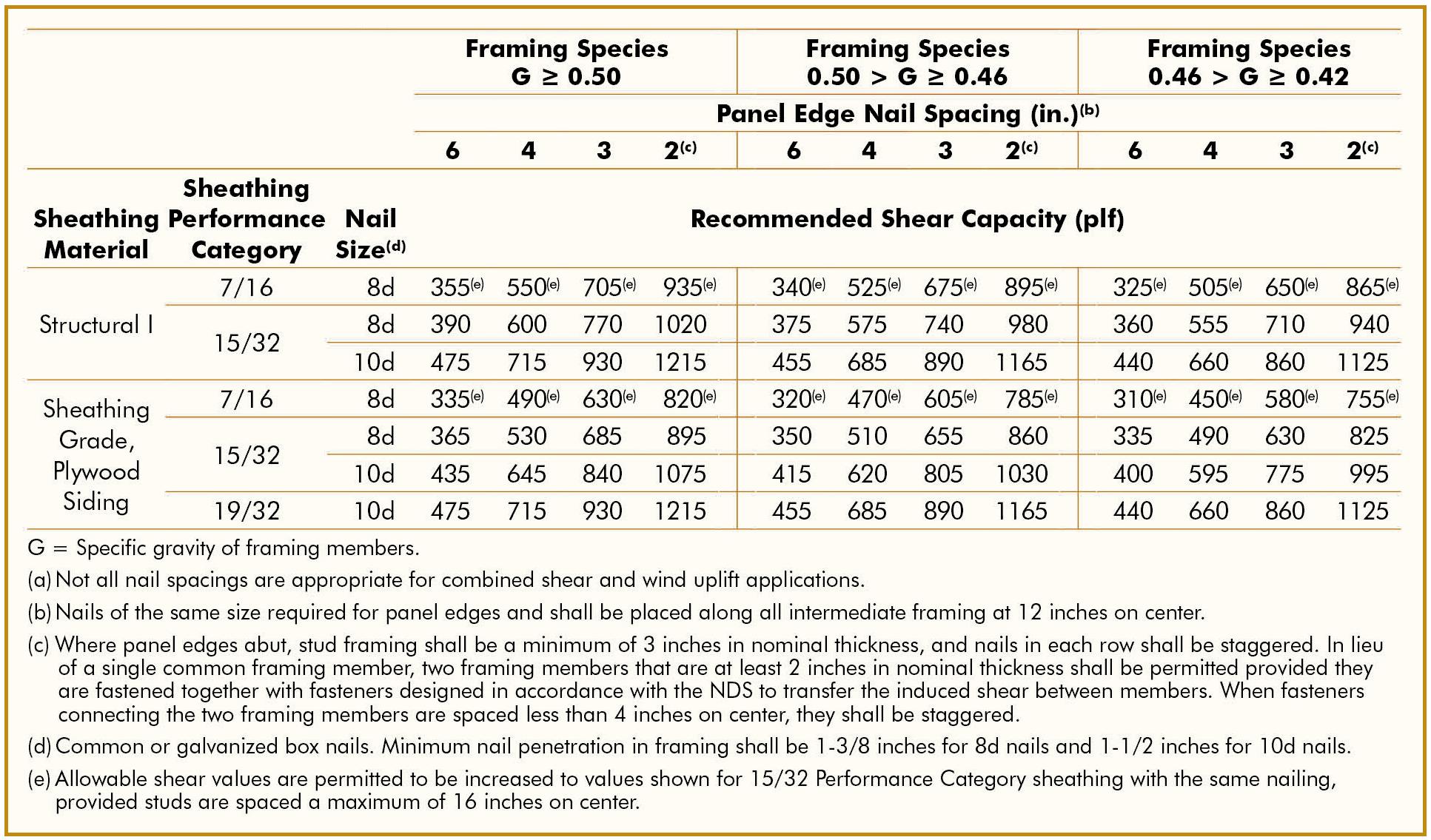
The designer should specify a double row of 8d nails at 3 inches on center at top and bottom plates (see Footnote f to Table 4 and Figures 1, 2, 3 (online), and 4 ), which satisfies the combined shear and uplift requirements for this wall segment. For the shear of 420
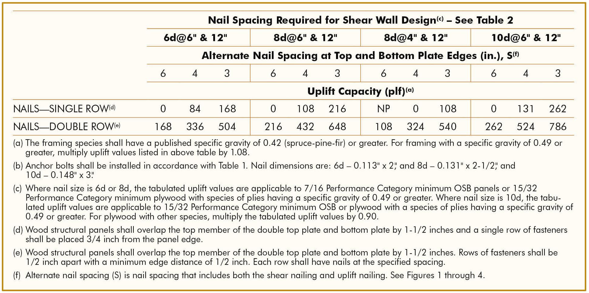






Figure 2. Panel attachment for shear and uplift – at rim joist.
Figure 4. Panel attachment for shear and uplift – at raised wood floor.
plf and uplift of 570 plf, this segment is required to use 5 8-inch anchor bolts spaced at 16 inches on center with 3- × 3- × 0.229inch square steel plate washers from Table 1(online) 8d nails and framing G of 0.50.
Note that the designer must still size the hold-down for the ends of the segmented shear wall based only on the design shear, as is done in shear walls designed for shear only. Similarly, for the perforated shear wall method, hold-downs are required at the ends of the perforated wall and are designed in the same manner as walls without wind uplift. Uplift forces resulting from wind uplift at headers over windows and doors may still have to be resisted by straps or other tie-down devices as when conventionally framed.
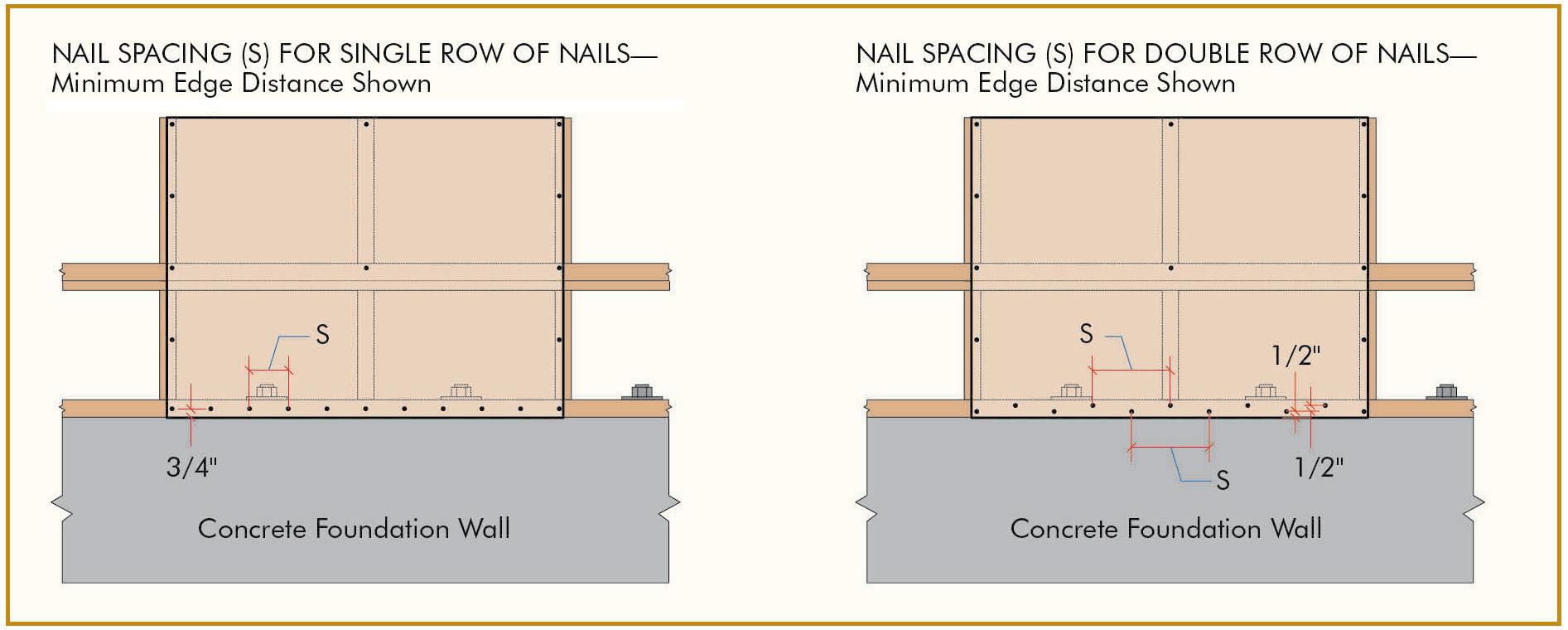
The installation of wood structural panel walls for resisting combined shear and wind uplift loads shall be as follows:
a) Multiple rows of nails applied at panel ends and edges shall be installed in accordance with Figure 1. Panel splice that occurs across studs or horizontal framing such as rim joists shall be installed in accordance with Figure 2
b) All horizontal joints shall occur over framing or blocking and shall be attached per Figures 2, 3 (online), and 4.
c) On single-story construction, panels shall be attached to bottom plates and top member of the double top plate. Lowest plate shall be attached to foundation with minimum 5⁄8-inch bolts at a specified spacing with 3- × 3- × 0.229-inch steel plate washers, and with minimum embedment of 7 inches or by connectors of sufficient capacity to resist the uplift and shear loads developed in the wood structural panel sheathing or siding walls.
d) On two-story construction, upper panels shall be attached to the top member of the upper double top plate and to rim joist at bottom of panel. The panel edges need not fall in the center of the rim joist. Upper attach ment of lower panel shall be made to rim joist and lower attachment made to lowest plate at first-floor framing, which shall be attached to foundation with minimum 5 8-inch bolts at a specified spacing with 3- × 3- × 0.229-inch steel plate wash ers, and minimum embedment of 7 inches or by connectors of sufficient capacity to resist the wind uplift and shear loads developed in the wood structural panel sheathing or siding walls. When a shear and uplift connection is made at a rim joist or with an inter-story splice, the rim joists and/or splice plates must have the abil ity to withstand the resulting tensile stresses perpendicular to the grain. Since sawn lumber, glulam, and most SCL do
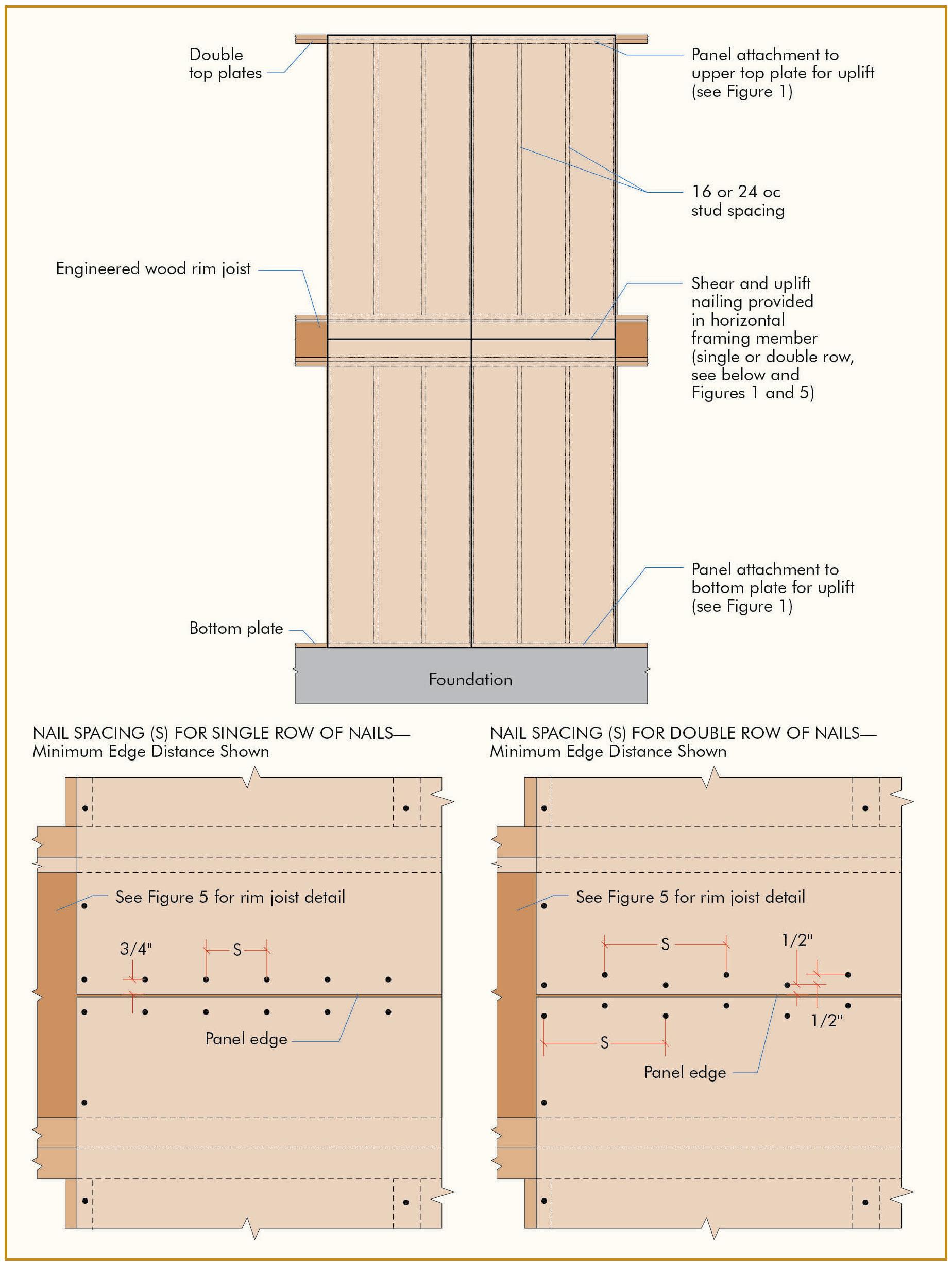
Reduce RFIs, steel tonnage and project costs. When you work with our engineers early in the design phase, you will streamline the specification and design of the steel joists and deck on your projects. Together, let’s build it better.
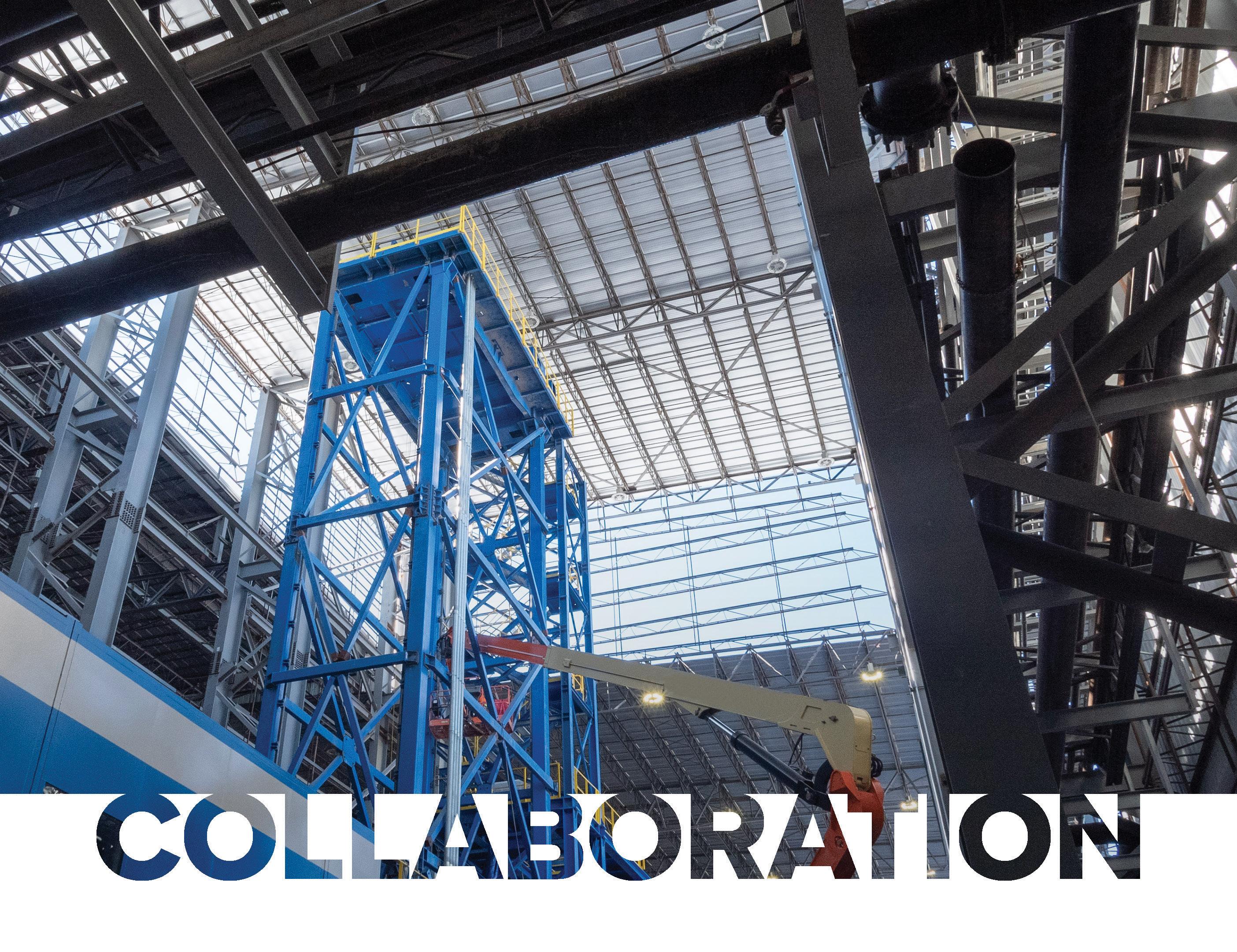

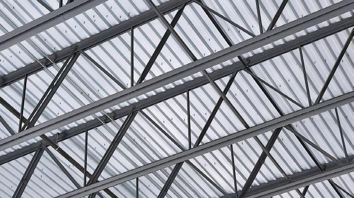
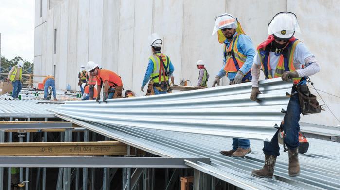
Top publications from ICC help you learn, interpret and apply the code



2021 IBC Code & Commentary Volumes 1 & 2 Search #3010S21 at shop.iccsafe.org
This helpful set contains the full text of 2021 IBC, including tables and figures, followed by corresponding commentary at the end of each section to help code users understand the intent of the code provisions and learn how to apply them effectively. Volumes also sold separately.
Reinforced Masonry Engineering Handbook, 9th Edition Search #9346S9 at shop.iccsafe.org
Based on 2021 IBC and TMS 402/602-16, MIA’s newly updated Handbook eliminates repetitious and routine calculations to help designers save time. In addition to the code requirements, it provides sound engineering practice, detailed explanations, 90+ examples, and hundreds of drawings.
Concise, visual explanations provide an overview of the code without complex explanations. Each book contains design aids, figures, flowcharts and examples to provide step-by-step procedures that engineers can follow to determine loads and correctly apply the code.
Flood and Tsunami Loads: Time-Saving Methods Using the 2018 IBC and ASCE/SEI 7-16 Search #9021S18 at shop.iccsafe.org
Seismic Loads: Time-Saving Methods Using the 2018 IBC and ASCE/SEI 7-16 Search #9022S18 at shop.iccsafe.org
Wind Loads: Time Saving Methods Using the 2018 IBC and ASCE/SEI 7-16 Search #9023S18 at shop.iccsafe.org
Rain, Snow, and Ice Loads: Time-Saving Methods Using the 2018 IBC and ASCE/SEI 7-16 Search #9020S18 at shop.iccsafe.org


Easy access, seamless onboarding, administrative reporting
Tailored for teams of 20 or more, a customized Enterprise package enables organizations to search, share, collaborate and manage building codes all in one place. This can help to save valuable time, reduce costly errors and improve a firm’s


To schedule a demo or for more information, contact Phil Anthony panthony@iccsafe.org. your free 14-day trial, visit

not have a published allowabletensile stress perpendicular to the grain, the shear and uplift connection can be made by a wood structural panel splice plate that is sandwiched between the wall sheathing/siding and the rim joist or splice plate. This wood structural panel splice plate must be of the same thickness, grade, and strength axis orien tation as the wall sheathing/siding material. This can be seen in Figures 5 and 6. Note that OSB or plywood rim joists are a suitable material for the shear and uplift splice connections shown in Figures 2 through 6
e) If a wood structural panel splice plate is to be used over a lumber rim joist, due to the potential for shrinkage of the lumber as it dries out, the wood structural panel splice plate shall be cut slightly under height (approximately ¼ inch) to permit room for shrinkage of the rim joist.
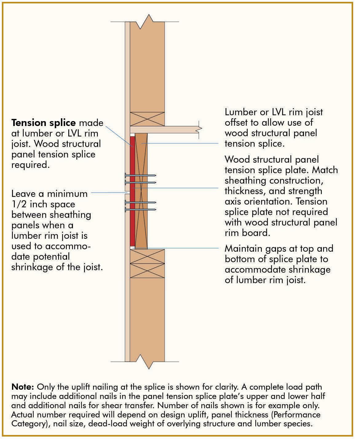
f) Where windows and doors interrupt wood structural panel sheathing or siding, framing anchors or connectors shall be used to resist the appropriate wind uplift loads, as required.
g) Roof or upper-level uplift connectors shall be installed on the same side of the wall as the sheathing to pre vent twisting of the top plate due to eccentric loading. This may be accomplished by installing the roof-to-wall connectors (hurricane ties) on the outside of the wall beneath the wood structural panel sheathing. It is also possible to install the roof to wall connectors (hurricane ties) on the outside of the wall over the wood structural panel sheathing or to install both the roof to wall con nectors (hurricane ties) and top plate to stud connectors on the inside of the wall when the recommendations of connector manufacturers, such as Simpson Strong-Tie, (www.strongtie.com) are followed.
h) When wood structural panels are used and centered over the rim joist, as shown in Figure 3(online), an engineered wood rim board is recommended for dimension (depth) compati bility with I-joist floor framing and low dimensional changes.
Recommendations provided in the APA System Report SR-101 are subject to the following conditions:
a) The structural systems provided in the report shall be designed by a design professional qualified in wood design and installed in accordance with the installation requirements specified in the report.
b) The structural systems shall be constructed with wood struc tural panels meeting the requirements of DOC PS 1 or PS 2 and trademarked by an approved agency required by the code.
c) The structural systems shall be limited to dry service conditions where the average equilibrium moisture content for solid-sawn lumber is less than 16 percent.
d) The latest copy of APA System Report, Form SR-101 can be downloaded for free from www.apawood.org/resource-library . ■
Please note that Figure 3, and Tables 1 and 3, are included in the online version of this article (STRUCTUREmag.org).

This article was previously published in the February 2015 APA System Report, Form SR-101. It is reprinted with permission.
Figure 5.
Figure 6. Required sheathing/siding shear and uplift splice between plates.
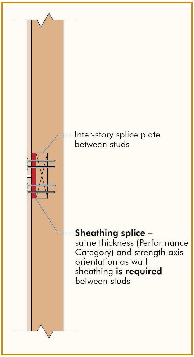

For centuries, bamboo has been the natural building material of choice due to its strength and sustainability. Those same properties are what make Nucor Tubular Products’ HSS the steel of choice for today’s engineers and architects. We use recycled steel and electric arc furnace (EAF) technology to craft our HSS, making it the lowest-emissions steel and the most sustainable HSS produced in North America.

Whether you need HSS for a long span truss or a handrail, make your project the most sustainable—and strongest—it can be with Nucor Tubular Products.
100% Made and Melted in the USA
In consulting engineering practice, struc tural engineers face new ethical issues from time to time. One such occurrence happened recently when our firm was asked to take over a project started by another engineer. Unfortunately, taking over a project started by another engineer has legal and ethical impli cations, and my research found little written material on the subject.
A client may assign a project to a new con sulting structural engineer for various reasons, including – expertise, manpower, produc tion schedules, and project costs. There are also options for different engineers cooperat ing on a project, and engineers often prefer these options, but clients do not always agree. Therefore, how to replace/supersede an engi neer who has been working on a project for some time while being ethical is uncharted territory for many and is discussed herein. Replacing or superseding an engineer also has legal implications, but they are not part of this writing.
Engineering Ethics is a field of moral principles; it sets the moral obligations of engineers to society, clients, peers, and their profession. It closely relates to philosophy, science, technology, history, and the humani ties. The Code of Ethics for engineers is formulated by Boards of Ethics affiliated with professional organizations such as the National Council of Structural Engineering Associations (NCSEA), the National Society of Professional Engineers (NSPE), and the American Society of Civil Engineers (ASCE), etc. Ethics is being taught in engineering schools, yet some question the need, claim ing that acting ethically is a moral obligation of every engineer and that ethical behavior is deeply engrained in the engineer’s humane upbringing and cannot be learned. However, the competition of free markets sometimes places engineers on opposite sides and with contradictory interests, giving rise to moral and ethical dilemmas.
When an engineer is replaced/superseded, a perception is created about the engi neer’s abilities, competence, experience, etc. Therefore, for some engineers, being replaced/superseded is undesirable regardless of the stage of the contract or design. For some, it is a matter of pride and reputation; it is also a financial matter and a matter of
the assigned personnel and their morale. It is a matter of sound practice for some to stay on the job until the end. A project begun is a project completed, say some. Avoiding a project from the beginning is better than starting and abandoning it.
It is critical to ensure that replacing/super seding is properly executed ethically. But before ethical issues can be addressed, the following definitions need to be explained.
All engineering codes of ethics subscribe to a code of conduct that prescribes principles of public safety and honor, life, law, and the environment. But specifically, some codes state the following:

• Do not accept any engagement to review the work of another profes sional engineer for the same client except with that engineer’s knowledge or where the connection of that engineer with the work has been previously terminated.
• Do not maliciously injure the reputation or business of another professional engineer.
• Do not attempt to gain an advantage over other members of the profession.
• Give proper credit for engineering work, and uphold the principle of adequate compensation for engineering work.
In summary, do unto others as you would have others do unto you–has been paramount in human behavior thru centuries, even mil lennia. It is also at the core of the engineering code of ethics. Therefore, this mantra must be respected when replacing or superseding an engineer on a project.
It is essential to understand that the engi neer and the project (as considered herein) are different entities. The engineer is retained to help deliver a project by providing engi neering services. The project has at least two parts (and possibly more). Part 1 includes the preparation of documents and specifica tions, calculations, etc., and Part 2 includes construction administration. Because the engineer and the project are different entities, part of the project may or may not be replaced by the owner; that is, an owner may consider replacing/superseding the engineer, but the owner may keep the project thus far advanced. When considering replacing or superseding, the decision is often affected by the stage of the project and how advanced the project is.
Among the various available definitions, the following was selected for this article: a profes sional engineer licensed in a respective state who is appointed by the owner and acceptable to the city; acting reasonably as the engineer responsible for the preparation, sign, seal, date, and issue (or file) documents related to design and construction.
Therefore, an engineer preparing designs becomes the engineer-of-record after signing, sealing, dating, and issuing (or filing) the documents. Before that, the engineer is not the engineer-of-record. When considering replace/supersede, it matters if the engineer is or is not the engineer-of-record.
Replacing and Superseding, as used herein, have different meanings. When an engineer is
When an engineer is replaced/superseded, a perception is created about the engineer’s abilities, competence, experience, etc. Therefore, for some engineers, being replaced/superseded is undesirable regardless of the stage of the contract or design.
replaced with a new engineer, the old project is abandoned, and the new engineer produces a new project from the start. When an engi neer is superseded, the old project remains, and the new engineer assumes it or its parts from where it is at the time of the change until its conclusion. When a project is in early development, an engineer can be replaced. When the project is well advanced, can the engineer be replaced? If he is superseded, the new engineer assumes responsibility for prior engineering designs, presumably with new calculations, drawings, etc. Thus the decision to supersede includes keeping the project as far as it has advanced and continuing it to its conclusion.
It is a momentous decision for an owner to replace/supersede an engineer; this should be done with serious considerations and analysis to benefit the project.
The introduction and definitions of ethi cal requirements for replacing/superseding are discussed above. However, the case of replacing/superseding an existing engineer raises ethical and legal issues for consulting engineers. It is a client’s option to replace or supersede an existing engineer with another. But engineers have the ethical duty to transi tion appropriately.
Generally, the following scenarios are common: the current engineer is notified of the client’s intentions. Then the engineer is asked to conclude contract obligations on the project, stop work and submit all applicable invoices to date. The engineer is also asked to submit a statement of no-objection to be replaced/superseded by another engineer.
As mentioned, the engineer and the project are different entities and should be treated differently. If the project stage dictates replacing or superseding, then the proce dure for replacing differs from the procedure required for superseding. Replacing can be done at any time because the project is also
replaced. However, replacement is no longer an option if the project is advanced and superseding is required. When supersed ing, the project remains and the superseding engineer continues it. When superseding, the following actions are recommended for the superseding engineer:
1) Always communicate with the client properly and truthfully. The client should be informed early of your ethi cal responsibilities to your fellow peers and the proper ethical path needed for superseding an engineer.
2) Do not opine on an existing project except after receiving affirmation from the current engineer.
3) Obtain a release from the current engineer, preferably in writing. Confirm that the engineer has been paid and that there are no unresolved contractual obligations.
4) As an engineer-of-record, designs and drawings must be developed under your supervision. Therefore, create or recreate drawings and calculations as needed.
5) Building Department filing needs to supersede prior fillings, as needed. Questions of drawings ownership and design rights are legal issues to be answered by legal departments. Additionally, circumstances may dictate variations that can affect all parties. Still, the emphasis herein is on the replac ing/superseding engineer. All involved are responsible for making the transition ethi cally proper and communicating truthfully throughout the transition while maintaining the professional integrity of all parties. It is best to stay on the sidelines when in doubt and not compromise ethically.
Replacing or superseding an engineer on an ongoing project is difficult; for the transi tion to occur flawlessly, ethical and legal issues must be confronted and dealt with
professionally. The ethical duty to ensure a proper transition falls on all parties, but the replacing/superseding engineer must high light the proper ethical transition method. You can find a list of the ethical requirements to be adhered to in the codes of ethics spon sored by various engineering organizations.
1) NCSEA – National Council of Structural Engineers Associations
i. Give proper credit for structural engineering work to those contrib uting and recognize the propriety interests of others.
ii. Avoid procuring, copying, or otherwise using computer files, software, or intellectual property without the consent of the product or property owner.

2) ASCE – American Society of Civil Engineers
i. Engineers shall build their profes sional reputation on the merit of their services and shall not compete unfairly with others.
ii. Engineers shall act in such a manner as to enhance the honor, integrity, and dignity of the engineering profession.
3) NSPE – National Society of Professional Engineers
i. Engineers shall not promote their own interests at the expense of the dignity and integrity of the profession.
ii. Engineers shall not attempt to obtain employment or advance ment or professional engagements by untruthfully criticizing other engineers or by other improper or questionable methods.
iii. Engineers in private practice shall not review the work of another engineer for the same client, except with the knowledge of such engineer or unless the connection of such engineer with the work has been terminated.
iv. Engineers shall give credit for engineering work to those to whom credit is due and will recognize the propriety interests of others.
■
A similar article will run in an upcoming SEAoNY publication.
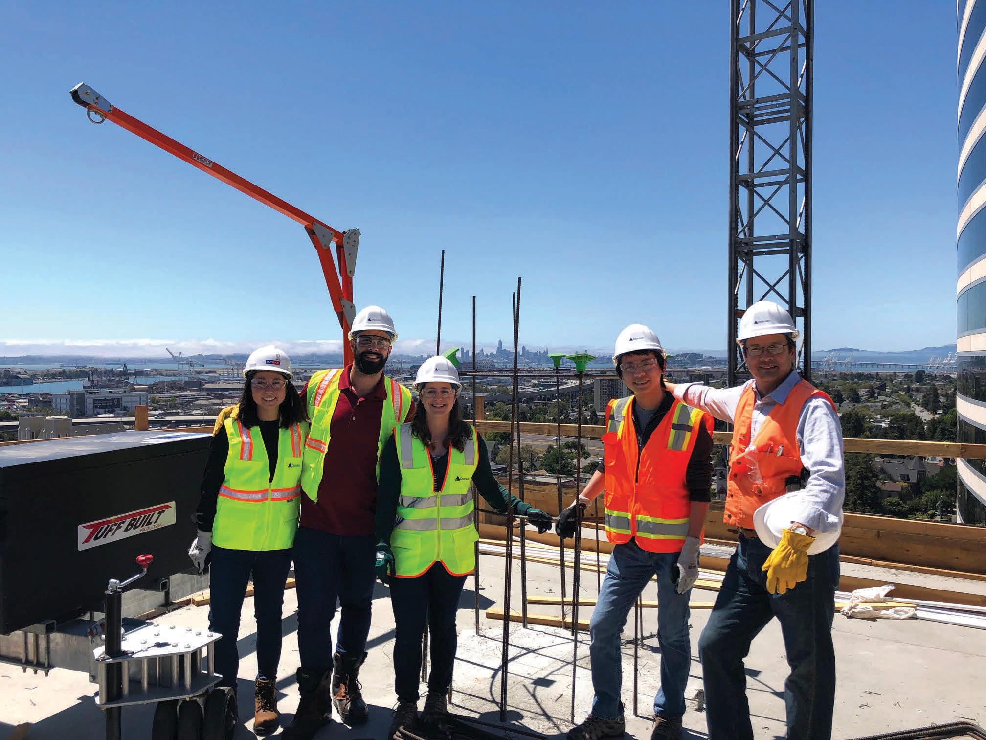



Over the past few years, a clear trend has emerged in major sports facility designs in the form of lightweight, transparent, and translucent materials for roofing and façade applications.
Recently constructed state-of-the-art facili ties for the National Football League and Major League Soccer have included trans parent and translucent foil membranes as the roofing and/or façade material of choice. Additionally, several proposed roofed ball parks in Major League Baseball are also reviewing the materials.
Transparent materials are developing to incorporate higher mechanical strength and better thermal performance. To date, ethylene tetrafluoroethylene (ETFE), in particular, has captured the imaginations of stadium owners, engineers, and designers and has become the material of choice.
The benefit of ETFE roof and façade applica tions is that they create an authentic, outdoor atmosphere in an indoor, conditioned space, providing a protected and temperature-con trolled experience. In addition, the material is lightweight, reducing structural support requirements and costs – especially for longspan roofs – and allowing for lighter, often more elegant structures.

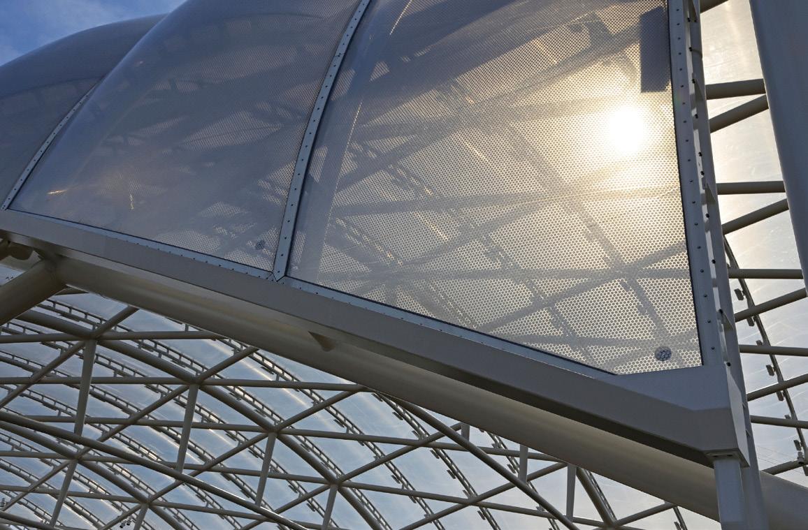
A clear but static roof eliminates the need for mechanization and the operational and main tenance costs of a retractable roof solution. Additionally, abundant natural light can reduce lighting and energy costs during operation.
However, conventional ETFE has some significant limitations, including min imal mechanical strength and capacity to support environmental loads due to snow, ponding water, and high winds. As a result, structural elements must be spaced close together, and cable reinforcement is frequently necessary. ETFE also exhibits poor or non-existent intrinsic thermal properties and must be layered and/ or fritted to improve thermal performance, substantially compromising the desired clar ity. ETFE also has poor acoustic properties, creating challenges with sound management in large spaces.
Fortunately, revolutionary transparent materials are currently being developed to incorporate higher mechanical strength and better thermal performance. Researchers and material specialists at Walter P Moore are partnering with manufacturers to develop better solutions for each new project.
Utilizing a variety of coatings, laminations, and new product applications, the next gen eration of transparent foil technology will replace conventional ETFE materials with

advanced, customizable composite solutions for any project.
Foils that provide enhanced strength, clarity, thermal and acoustic performance, customizable colors, and even missile-impact resistance will expand the market into applications typically reserved for glass and metal panels. These new options will allow designers to redefine what is possible in long-span and lightweight structures.
But why stop there? Creating composite cladding foil paves the way for technologies borrowed from aerospace, automotive, and other industries to be included within the material without sacrificing natural light.
Vulcraft’s flush frame connections are modernizing steel joist floor systems. Designed to reduce floor-to-floor heights, simplify MEP installation, and accelerate deck installation, studies have shown that our flush frame connections also significantly mitigate floor vibration.*
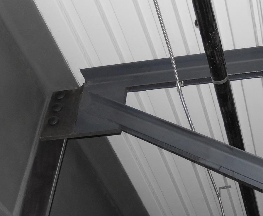
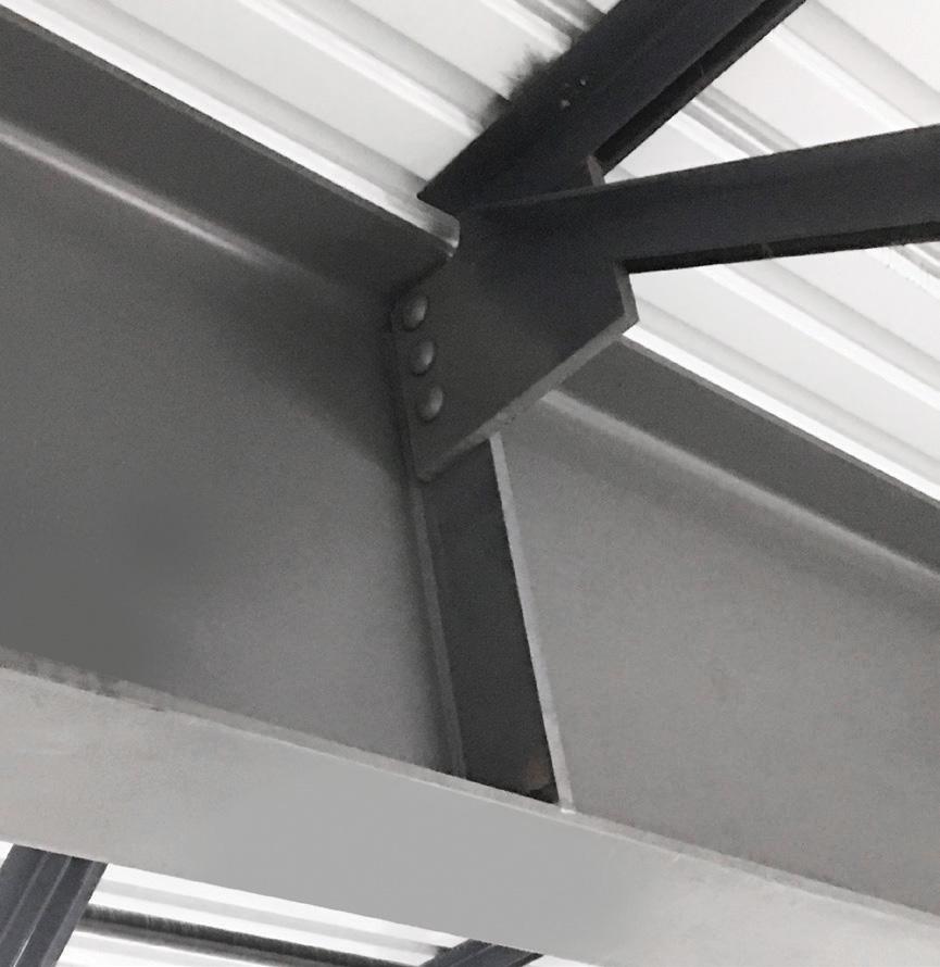
Long recognized as a leader in innovation, versatility, and cost efficiency, Vulcraft’s steel joist floor systems provide more options and less vibration.
*As measured by finite element analysis and manual calculation methods.
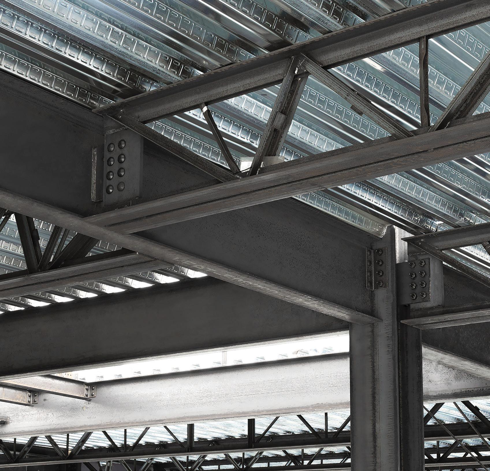
Soon, membranes will incorporate nanoparticles to enable electrochromic technology for active shading, thermochromic technology for active infrared radiation reflectivity, active color, and imaging – even transparent solar harnessing.
Electrochromic technology, currently used in energy-efficient “smart” windows in buildings and rearview mirrors in automobiles,



will transform membranes from transparent to opaque with electric current and could be used to black out otherwise clear roofs for concerts or other live shows.
ermochromic technology, which can selectively target specific wavelengths of infrared radiation, will control solar heat transmission while filling the space with the full visual spectrum of natural light.
Eventually, nanotechnologies employing particles triggered by surface temperature will enable venue owners in colder climates to allow heat to enter the space in winter but then reflect heat in the summer. For those in warmer climates, the technology could allow latent heat built up during the day to escape during cooler night hours.
As light-emitting diodes (LEDs) become smaller and more efficient, nano-LEDs may be applied directly to a composite foil membrane. Organic light-emitting diodes (OLEDs), where the illuminating layer is a film that emits light in response to an electric current, may allow the material itself to become the light source. As LED and OLED technology develops and is adequately scaled, image projection within the material may allow for branding, advertising, and even liveaction broadcasting directly from the membrane.
Finally, transparent solar harnessing, which will essentially employ the entire membrane as a giant photovoltaic panel, may eventually be used to supply energy for the entire venue and perhaps the surrounding community.
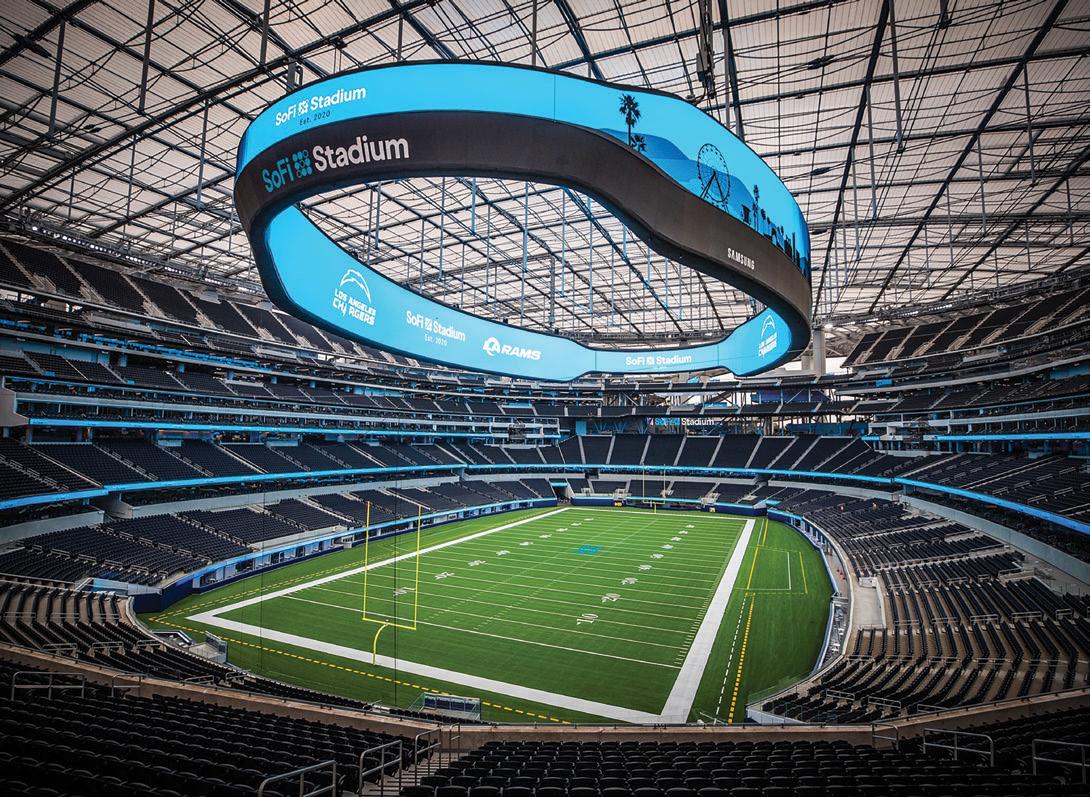
While there have been relatively few innovations in long-span roof design in the last several years that have significantly altered the landscape, materials research and development around lightweight, transparent roofing and façade materials may prove truly game-changing.
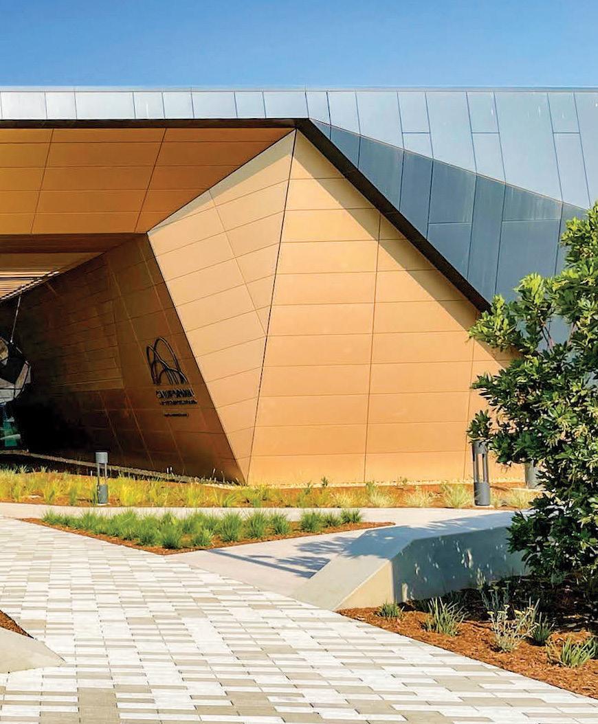
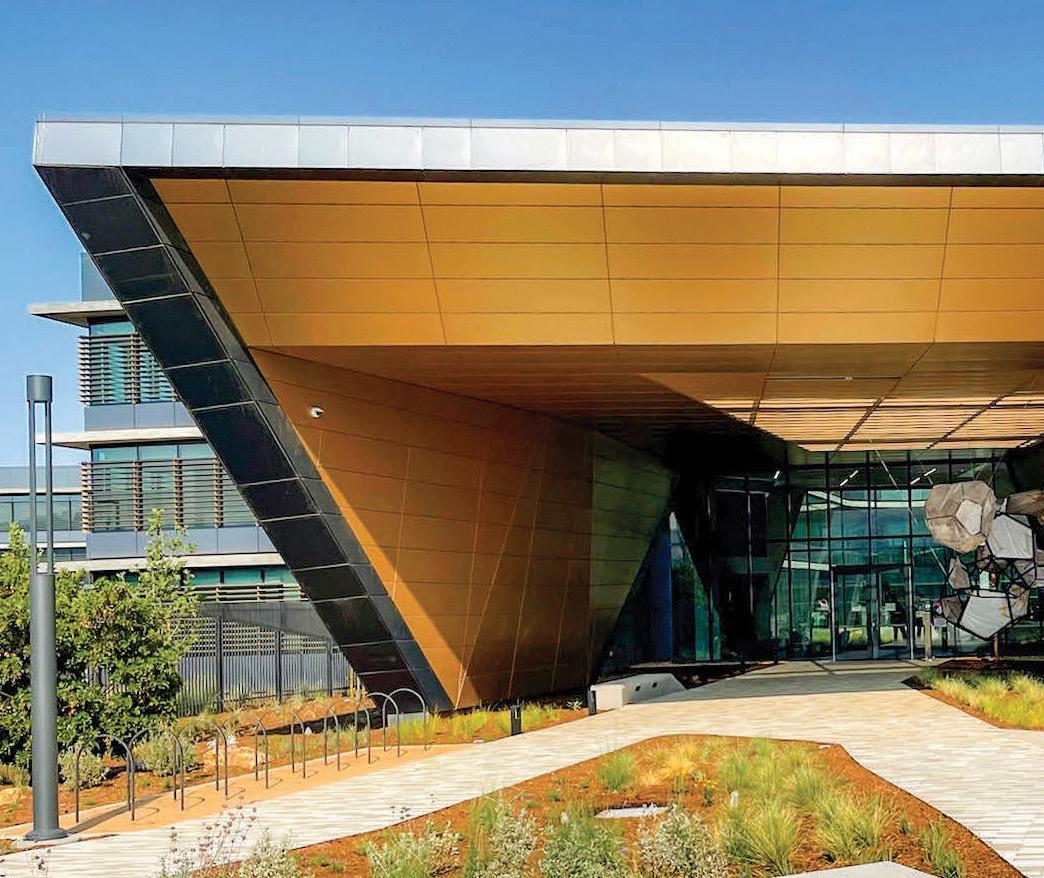
■
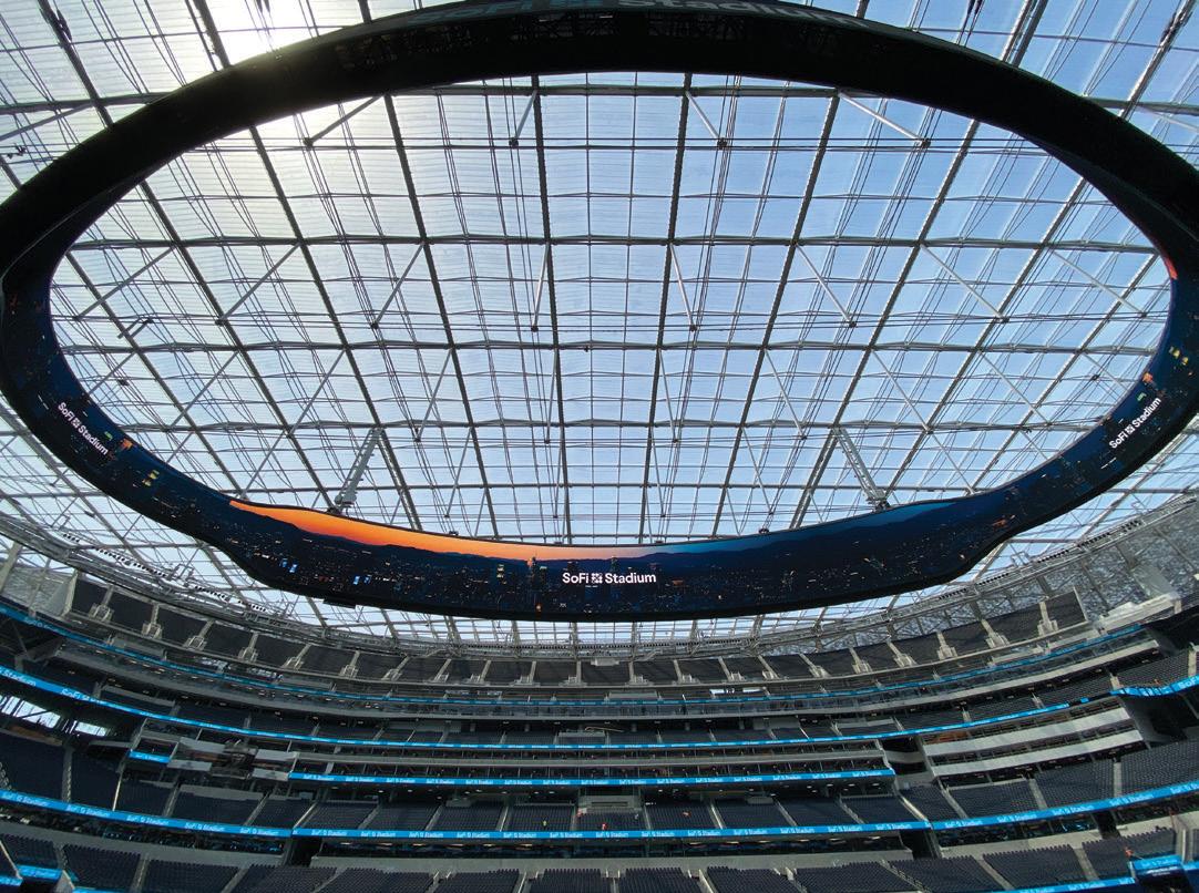
ASDIP Structural Software



Phone: 407-284-9202
Email: support@asdipsoft.com Web: www.asdipsoft.com
Product: ASDIP SUITE
Description: Includes the design of beams, columns, walls, base plates, anchor rods, shear lugs, retaining walls, moment connections and more, per the latest design codes. For over 30 years, we have developed powerful yet simple-to-use tools to easily analyze, design, optimize, and check your structural members.
Phone: 800-424-2252 Email: info@enercalc.com Web: https://enercalc.com
Product: Structural Engineering Library/ ENERCALC 3D/ENERCALC for Revit
Description: ENERCALC’s 40th year brings new modules: Steel Base Plate w/FEM, General Footing w/FEM, 7 retaining wall modules, and ENERCALC 3D. We have introduced substantial interface and performance improvements, plus ENERCALC for Revit (optional). Meet deadlines by saving time with ENERCALC while saving money with budget-friendly monthly and annual subscriptions.
Phone: 800-645-0616
Email: jenniferm@h-b.com Web: h-b.com
Product: ProWall Tools Featuring Thermal Brick Support (TBS)




Description: Free software for architects, mason contractors, specifiers, and designers, allows users to easily incorporate TBS into projects. Brick support design that can move the shelf angle away from the wall, reducing thermal transfer. Allows fast analysis of a brick support design when entering design parameters into a picture graphic.
Phone: 800-707-0816
Email: info@iesweb.com Web: www.iesweb.com

Product: IES Building Suite
Description: When you need quick, easy, and versatile structural analysis and design, look no further than IESWeb.com Download any product in 2 minutes for a free trial. See pricing and licensing options online. Proven by thousands of engineers for over 27 years. Fully supported.
Phone: 866-859-6757
Email: info@redbuilt.com Web: www.redbuilt.com
Product: RedSpec™
Description: A convenient, user-friendly design program that lets you quickly and efficiently create floor and roof design specifications using Red-I™ joists, RedBuilt™ open-web trusses, RedLam™ LVL, glulam beams, and dimensional lumber. RedSpec is provided free of charge to registered users. For support, contact us by email at RedSpec@RedBuilt.com
Phone: 949-951-5815
Email: candicec@risa.com Web: risa.com
Product: RISA-3D

Description: The next step in the evolution of the structural design software. With features including the design of cold-formed steel, AISC and ACI code updates, seismic improvements, and the introduction of orthotropic plates, engineers can effortlessly complete complex projects utilizing any material. Integrate seamlessly with Revit for easy modeling.
Listings are provided as a courtesy, STRUCTURE is not responsible for errors.
Email: hssinfo@steeltubeinstitute.org Web: steeltubeinstitute.org Product: HSS Connex
Description: A free web-based tool that offers designers a simple way to check HSS wall thicknesses to aid in efficient HSS connection design. These local limit state checks are helpful to ensure HSS wall thicknesses are adequate at connections.
Phone: 678-737-7379
Email: jodi.hendrixson@trimble.com Web: www.tekla.com/us

Product: Tekla Tedds
Description: Automates repetitive and error prone structural and civil calculations, allowing engineers to perform 2-D frame analysis, access a large range of automated structural and civil calculations to U.S. codes, and speed up daily structural calculations.
Product: Tekla Structural Designer
Description: Engineers have the power to analyze and design multi-material buildings efficiently and cost effectively. Fully automated and packed with unique features for optimized concrete and steel design, Tekla Structural Designer helps engineering businesses win more projects and maximize profits.

 By Gabriel Maser, Esq.
On June 1, 2022, the U.S. Federal Emergency Management Agency (FEMA) Administrator Deanne Criswell announced a National Initiative to Advance Building Codes, a new government-wide effort to boost national resiliency and reduce energy costs. Under the initiative, U.S. federal depart ments and agencies will review federal funding and financing of building construction to ensure projects follow updated model codes and provide incentives and support for communities to adopt modern building codes. In addition, members of the Mitigation Framework Leadership Group (MitFLG) will review their infrastructure grantmaking processes to ensure that they align with and support the adoption and use of current editions of the International Residential Code (IRC) and International Building Code (IBC). FEMA chairs the MitFLG, which consists of another 13 federal agencies, including the Department of Housing and Urban Development (HUD), the Department of Energy (DOE), and the Department of Health and Human Services (HHS).
The announcement was made at the Florida International University Wall of Wind in Miami, Florida, at the start of the Atlantic hurricane season. In the aftermath of Hurricane Andrew, which struck South Florida nearly 30 years ago and resulted in 65 deaths and more than $26 billion in damages, Florida significantly strengthened its building codes and enforcement practices. As a result, according to FEMA, Florida’s codes, based on the I-Codes, have prevented over $1 billion in losses annually since 2000.
FEMA maintains that by modernizing building codes, communities will not only save money through lower energy costs and protecting their property, but lives will be saved by ensuring that the U.S. infrastructure remains resilient in the face of a changing climate and the associated extreme weather events. FEMA has com mitted to working with stakeholders like the International Code Council (ICC) to leverage collective knowledge and experience to bolster the adoption of the latest building codes and standards across this nation.
Every year, the U.S. government spends hundreds of billions of dollars supporting building construction and retrofits through grants and other incentives. FEMA views the adoption of current building codes as the most effective means to enable communities to become more resilient to natural hazards that are increasing in frequency and severity due to the changing climate. Yet, FEMA is currently the only U.S. federal agency that requires the construction it funds to adhere to current, hazard-resistant codes. FEMA is also the only U.S. federal agency that incentivizes state, local, tribal, and territorial (SLTT) gov ernments to adopt and effectively implement resilient codes through its infrastructure grants. The National Initiative to Advance Building Codes aims to change that.
According to the Natural Hazard Mitigation Saves: 2019 Report, requiring the current IBC and IRC prevents roughly $14,000 in losses per building in jurisdictions where codes have not been updated in the past two decades. This represents an $11 to $1 return on invest ment in many of these areas that mitigate the loss of life and injuries, property damage, business interruptions, as well as first responder and annual homeownership costs.
According to FEMA, in recent years, 30% of new construction has occurred in these areas. According to DOE, nearly half of states’ residential energy codes are currently at least 15% less efficient than the 2021 International Energy Conservation Code (IECC). Per DOE, modern energy codes can save households an average of $162 each year on utility bills. Without federal resilience and energy conserva tion requirements, federally-assisted construction defaults to locally adopted codes and standards.
Under the new initiative, MitFLG agencies are charged with:
• Ensuring, to the extent feasible, that current programs fund ing and financing new and substantially rehabilitated homes and buildings follow current editions of relevant I-Codes, including, for example, the IRC, IBC, and International Existing Building Code (IEBC).
• Leveraging $225 million in DOE funding through the Bipartisan Infrastructure Law to support the adoption and implementation of updated building energy codes, such as the IECC and International Green Construction Code (IgCC).
• Providing incentives and support for SLTT governments to adopt and effectively implement modern building codes,
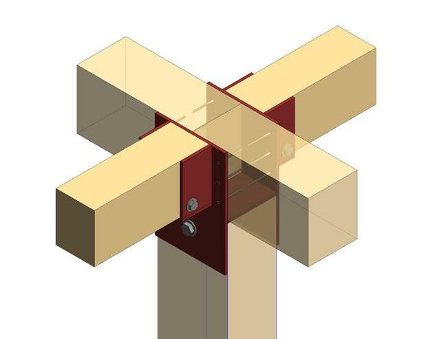
including through outreach, education, and technical support efforts like those envisioned in FEMA’s recently announced Building Codes Strategy.
•Leading by example to pilot above-code resilience and energy conservation efforts across the U.S. federal building portfolio.
•FEMA’s pre-disaster mitigation program, now called Building Resilient Infrastructure and Communities (BRIC), provides grants to fund code activities ranging from adoption and implementation to building department accreditation through a “Capability- and CapacityBuilding (C&CB)” set-aside for states, tribes, and territories. Additionally, states adopting the most recent editions of building codes and with Building Code Effectiveness Grading Scale (BCEGS) ratings 1-5 earn more points towards the competitive mitigation awards.

•HUD’s Community Development Block Grant Disaster Recovery (CDBG-DR) and Disaster Mitigation (CDBG-MIT) Programs require Public Action Plans from all grantees, which outline the use of funds, to include a description of how the grantee “will support adoption and enforcement of modern and/ or resilient building codes that mitigate against natural hazard risks, including climate-related risks and provide for accessible building codes and standards.” CDBG-DR/MIT awards may be used to support the adoption and implementation of hazard-resistant building codes. ese are also the only federal funds that can be used towards the local cost-share for FEMA grants.
• Additional information on Bipartisan Infrastructure Law Energy Codes Implementation Program can be obtained from the ICC.


Structural engineers rely on building codes and their code-referenced standards every day. Widespread adoption and enforcement of modern, up-to-date building codes ensure that engineers have the latest technology and tools to design and facilitate the proper construction of more resilient buildings. One example is a new provision in the
2021 IBC which now mandates structural observations (typically performed by a structural engineer) for all Risk Category III buildings. As respected members of the construction community, structural engineers can play a crucial role in advancing modern building codes.■
e online version contains a list of digital resources for topics discussed in this article. Visit STRUCTUREmag.org.


Getting off-site starts with using the right materials on-site. ClarkDietrich helps you do your best work as efficiently as possible. From framing to finishing, ClarkDietrich products and services save time, material and labor, so you can get the job done right and go grab some peace of mind.




e NCSEA Special Awards are bestowed on individuals who exemplify outstanding service and commitment to the association and the structural engineering field. ese dedicated servants, committed volunteers, and industry leaders were recognized and applauded at the Awards Celebration held ursday, November 3, at the NCSEA Structural Engineering Summit. Congratulations to this year’s best and brightest!
is award is presented to an individual who has worked for the betterment of NCSEA, member organizations, and the profession to a degree beyond the volunteerism norm. It is given to someone who has made a clear and indisputable contribution to the organization and, therefore, to the profession.
Emily Guglielmo, P.E., S.E., has nearly two decades of structural engineering experience and has spent her entire career with Martin/Martin. She began her career in their Colorado office and is currently a principal managing their San Francisco Bay Area office. She served on the NCSEA Board of Directors from 2015-2022, including as NCSEA President from 2020-2021. In addition, Emily was a founder and Chair of both the NCSEA Communications Committee and the NCSEA Young Member Group Support Committee. She is the incoming Chair of the Code Advisory Committee, having chaired the Wind Engineering Committee since 2019. A licensed SE, Emily has received several awards, including an SEI Fellow and the Susan M. Frey NCSEA Educator Award for effective instruction for practicing structural engineers.

is award is presented to an individual for exceptional dedication and exemplary service to a Member Organization and to the profession. e award is named for Robert Cornforth, a founding member of NCSEA and treasurer on its first Board of Directors.
Chun C Lau, P.E., S.E., P.Eng., F.SEI, F.ASCE, is a Managing Principal at Brown and Caldwell, Seattle, WA, with his practice focus on the design of environmental engineering structures. Chun joined SEAW in 1993 and has served in the following capacities: State and Seattle Chapter President 2017-2018; Seattle Chapter Vice President 2016-2017; Seattle Chapter Board 1998-2000; Instructor for the Lateral Force section of the Structural Exam Refresher Course; and, Exam Grader for the Washington State Specific Structural III Examinations. In addition, Chun has been serving as the SEAW delegate to NCSEA since 2011. He became the first SEAW member to serve simultaneously as both State and Seattle Chapter President in 2016-17 while serving on the NCSEA Board of Directors. Chun received the Seattle Chapter Engineer of the Year Award in 2018 and the Seattle Chapter President’s Award in 1996, 2017, 2019, and 2000 for his service to SEAW. He is currently serving on the 2023 Northwest SEA conference planning committee.

is award is presented at the recommendation of the NCSEA Code Advisory Committee to recognize outstanding individual contributions toward the development of building codes and standards. It is given in the spirit of its namesake, a person who made a long and lasting contribution to the code development process.
Gwenyth Searer, S.E., P.E., is a Principal at Wiss, Janney, Elstner Associates, Inc., a licensed Structural Engineer in six western states, and a licensed Professional Engineer in New York. Ms. Searer works on projects involving a wide variety of structural materials, including steel, concrete, timber, masonry, and aluminum. She has significant experience evaluating facade-access equipment and cladding systems, has conducted numerous in-situ load tests, and has investigated damage from six major earthquakes. Ms. Searer has been involved in developing building codes and standards since 2000. She served on the ICC Structural Committee for five code cycles; she is a voting member of the Main Committee of ASCE 7; the Chair of the Wind Committee of the Structural Engineers Association of California; and a Board Member of the Structural Engineers Association of Northern California.


This award was created to honor the late NCSEA Board President and advocate for the profession, Susan Ann “Susie” Jorgensen, who passed away in November 2020. The award is presented to individuals who have demonstrated exceptional leadership potential through their activities within NCSEA and/or their SEA (even if they did not serve in a formal leadership role). The award is to be bestowed on candidates who embody Susie’s passion, vision, and legacy of leadership. It is intended to celebrate the increased participation of emerging leaders and encourage recipients to engage (or continue to engage) in formal leadership.
Michelle Ryland, S.E., R.A., is a dual licensed structural engineer and architect with Klein and Hoffman in Chicago with over 11 years of experience in the repair, restoration, and adaptive reuse of Chicago’s vintage building stock. A graduate of the University of Illinois, Michelle joined SEAOI in 2012 and quickly became involved with the Young Engineers Committee, first organizing the group’s volunteer events before eventually serving as co-chair for three years. In 2018, Michelle was nominated by the SEAOI Board of Directors to serve as Illinois’ delegate to NCSEA, a position she held for 3½ years. In 2019, Michelle joined SEAOI’s Board of Directors, completing her term in June 2022. She currently chairs SEAOI’s PR/Outreach Committee and Structures Symposium Committee and co-chairs NCSEA’s Internal Communications Committee – all positions she has held for multiple years.


Samantha E. Brummell, P.E., is a Senior Project Engineer at Thornton Tomasetti. Most of her experience is in healthcare, residential, and commercial construction. Notable projects include Brooklyn Methodist New York-Presbyterian Hospital and 141 Willoughby. Sam holds a bachelor’s in Civil Engineering and a master’s degree in Structural Engineering, both from Cornell University, and is licensed in the State of New York. Sam has been a member of SEAoNY’s Student Outreach Committee since 2015. In 2016, she founded SEAoNY’s Young Members Group. She has been serving on SEAoNY’s Board of Directors since 2018. Additionally, she is a member of ASCE and Professional Women in Construction. Sam has been honored by C+S Engineer Media and ACEC nationally for her dedication to the AEC industry. She currently serves as a Visiting Assistant Professor at the Pratt Institute.

To all the attendees, presenters, sponsors, exhibitors, the planning committee, and staff for a successful SEI Electrical Transmission and Substation Structures Conference in Orlando!
ETS Conference leaders/mentors and first-time attending SEI Futures Fund student scholarship recipients had a great time learning, networking, and sharing insights.
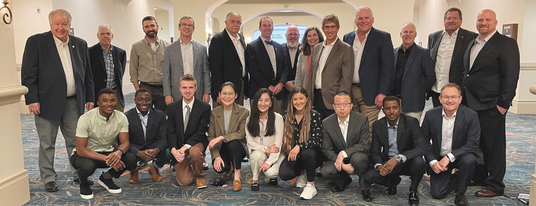
• Structures Congress May 3-6 in New Orleans – Apply for Student or Young Professional Scholarship
• Standards Series 2023 Check out the program and speakers, and register www.asce.org/SEIEvents

January 23-April 14, 2023
Modeling and Analysis of Structural Systems for Efficient Design GOCMAS23
• Apply multiple modeling approaches to the analysis of steel and concrete buildings
• Apply different calculation methods for validating the accuracy of the computed results
Rigging Fundamentals GOCRIG23
• Learn rigging safety and major laws that affect the industry, and work through basic lifting lug design and spreader design
• Understand how to start with a piece to lift and be able to design a complete rigging system to safely and efficiently lift that piece
Seismic Analysis of Building Structures GOCSABS23
• Describe the analysis process and requirements for the equivalent lateral force, the modal response spectrum, linear response history, and nonlinear response history analysis methods
• Determine which analysis methods are permitted for seismic analysis following ASCE-7 for a given structure based on the structure’s characteristics and seismic hazards
Using Examples to Illustrate ASCE 7-16 Wind Provisions GOCWLS22
• Apply the ASCE 7-16 wind provisions to real building types and design scenarios
• Understand the differences in building characteristics and how those differences influence the approach to wind design
For more information: go.asce.org/GOCs

The SEI Bridge the Gap program provides small grant funding from the SEI Futures Fund for eligible local SEI Chapters to run innovative programs promot ing student and professional member interaction to attract and retain students as life-long, active SEI members. Funds were granted this cycle for SEI Graduate Student Chapters at the University of Cincinnati, Oregon State University, and University of Texas, Arlington, and to professional SEI Chapters – East Central Florida, Illinois, and Lehigh Valley.
In June, the SEI Grad Student Chapter at Oregon State University held an event to visit the recently expanded Providence Park Stadium in Portland. Members from the local SEI chapters and the ASCE Section enjoyed networking with students and faculty members, a KPFF presentation on the expansion project, and a visit to the stadium to watch a game and observe some of the elements from the technical presentation.
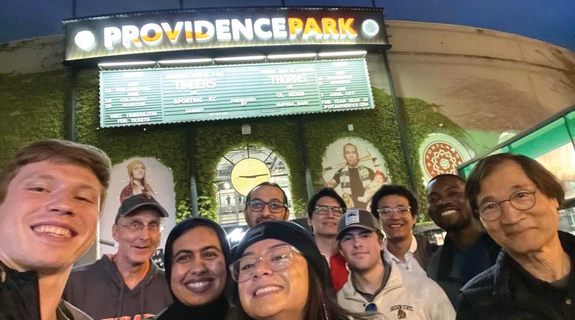
In September, the SEI Illinois Chapter held a networking dinner and interactive panel event, Preparing for a Career in Structural Engineering, at the Illinois Institute of Technology (where there is an active ASCE student chapter), and included outreach to the University of Illinois-Chicago and Northwestern University. Following a presentation on career paths in structural engineering, SEI IL structural engineering professionals rotated among small group tables of students discussing career topics and involvement in professional societies and answering questions.
Impact the future of structural engineering and programs like this with a gift to the SEI Futures Fund www.asce.org/SEIFuturesFund.

The chapter aims to serve and promote the structural engineering profession through various education and outreach activities, exposing students to cutting-edge research and industry practices, interacting with peer organizations and facilitating greater collaboration, and rais ing awareness among undergraduate students of career opportunities in structural engineering. http://cee.umich.edu
Learn more about SEI Chapters www.asce.org/SEILocal


April 12-14, Charlotte, N.C.
NASCC: The Steel Conference is the premier educational and networking event for the structural steel industry, bringing together structural engineers, steel fabricators, erectors, and detailers. The Steel Conference offers more than 130 sessions on topics ranging from Practical Advice for Reviewing Software Generated Connection Designs to Lateral Torsional Buckling and its Influence on the Strength of Beams and Keeping OSHA out of your Bank Account. In addition to practical seminars on the latest design concepts, construction techniques, and cutting-edge research, the conference also offers an extensive trade show featuring products ranging from structural design software to machinery for cutting steel beams, as well as plentiful networking opportunities
May 3-6, 2023, New Orleans, LA
The SEI Structures Congress has a robust technical program, engaging keynote speakers, and numerous networking opportunities. Engage, network, and learn with the community to work together to advance the structural engineering profession for a better future.
Do you know someone in your firm that is looking for ways to expand and strengthen their business skillset, gain experience serving on a committee, sharpen their leadership skills, and travel to interesting places? Then, please consider applying for a position on the committee. Committee member commitments include a monthly virtual meeting, working on relevant documents a few hours a month, and traveling to the winter and summer Coalitions’ meetings!
To apply, your firm should:
• Be a current member of ACEC
• Be a member of the Coalition of American Structural Engineers (CASE); or be willing to join the Coalition
• Be able to attend the groups’ regular face-to-face meet ings each year: August, February (hotel, travel partially reimbursable)
• Be available to engage with the committees via email and video/conference call
• Have some specific experience and/or expertise to contribute to the group
Your monetary support is vital in helping CASE and ACEC increase scholarships to those students who are the future of our industry. All donations toward the program may be eligible for tax deduction and you don't have to be an ACEC member to donate!
Donate today: www.acecresearchinstitute.org/scholarships

Congratulations to the 2022 CASE Scholarship winner, Taylor Drahota, from the University of Nebraska-Lincoln! View information about the scholarship and win ners at acec.org under “Awards.”

Invest in the future of our workforce. Donate to the
CASE has tools and practice guidelines to help firms deal with a wide variety of business scenarios that structural engineering firms face daily. So whether your firm needs to establish a new Quality Assurance Program, update its risk management program, keep track of the skills that engineers are learning at each level of experience, or need a sample contract document – CASE has the tools you need!
What’s Shaking? A new publication from CASE about Seismic Design
CASE Guideline 962- J – Business Practice Guidelines of Seismic Design for the Structural Engineer
The purpose of this document is to provide insights into structural engineering services in regions where there is a seismic hazard. This document shares key design considerations as well as business practice considerations. Numerous resources are available that provide a much more exhaustive and advanced technical presentation of important considerations when designing for earthquakes. Someone new to designing for earthquakes should consider taking a course in structural dynamics and seismic engineering, whether from a university or some other provider such as ASCE or NCSEA.
Check out the brand-new white paper by CASE:
Beyond the Code: Grade-Level Floors over Expansive Soils
CASE recognizes that the International Building Code or other governing codes do not address all aspects of structural engineering and design. Often, the most common issues are where the owners, the contractor, or the design team are not aligned to deal with what is not clearly addressed by the various codes or design guidelines. This is the first in a series of Beyond the Code white papers that collate design considerations that need to be discussed with the owners at the beginning of a project to establish a clear Basis-of-Design. By proactively bringing up the design consideration in front of the owners, the Structural Engineer can set realistic expectations and discuss the cost impact of alternative designs. This first white paper in the Beyond the Code series discusses the pros and cons of two structural design options for the grade-level floor in expansive soil regions. Keep an eye out for future installments in the series!
You can purchase these and other Risk Management Tools at www.acec.org/bookstore
You can also browse all of the CASE publications at www.acec.org/coalitions/coalition-publications. Is there something missing for your business practice? CASE is committed to publishing the right tools for you. Have an idea? We would love to hear from you!
If you are a CASE member, this tool and all publications are free. NCSEA and SEI members receive a discount on publications. Use discount code – NCSEASEI2022 when you check out.
Online October 31 through November 18, 2022
Smaller projects can be a core revenue driver for engineering firm project managers and firm principals. But, smaller projects still have the potential to carry significant risks that can drag on resources, profitability, and client satisfaction. The good news is that you can ensure that even the smallest projects deliver maximum profits with the right set of skills in your toolbox. Learn the skills, hacks, secrets, formulas, trouble-shooters, and problem-solvers that delight engineering firm executives and clients with small project progress and outcomes.
Jared Jamison, P.E, a consultant for PSMJ, will be presenting this live online program.
ACEC Coalition members receive a discount. Find more informa tion at www.acec.org/conferences under Coalitions.
Ibelieve that embracing fl exible work environments can benefit the SE industry, firms, and employees – if the industry is willing to put in the effort to incorporate the change. It is time to create a new normal. I urge SE leaders to embrace the disruption caused by the pandemic and to grow and adapt instead of trying to “return to normal.”
STRUCTURE’s April 2022 Editorial suggested that it was not possible to replicate one-on-one mentoring through an internet connection. I beg to differ.
As noted in the April Editorial, a common concern about flexible work is the coaching and mentoring of young engineers. However, many in-person interactions can be replicated in flexible work environments. As examples:
• How do you replicate a young engineer overhearing a manager’s interaction with clients? Managers can invite their engineers on conference calls to listen to those client interactions.
• How do you replicate a young engineer’s interaction with colleagues? Teams chats and Slack channels can be developed for project teams and technical topics. Most young engineers are already experts at interacting online with peers and can also communicate effectively with colleagues virtually.
• How do you replicate sketching ideas or reviewing a drawing set as a team? Take advantage of technology and buy engineers and managers a tablet with a touch screen and digital pen. Screen sharing and PDF editing software can allow everyone to contribute together. ese virtual interactions need to be intentional. However, deliberate communication and coaching can also allow for more productive time and fewer interruptions for both managers and engineers. ese active training methods can be more impactful than relying on passive techniques like overhearing office conversations. While interactions in an office can be valuable, they are not necessary for 40+ hours every week.
In an increasingly online world, flexible work and improved virtual communication skills can have benefits beyond the development of young engineers. ey can improve client relationships, as many architectural firms embrace hybrid work. ey can strengthen intra-office relationships by facilitating more connections between colleagues in different
offices. ey can strengthen the ability of engineers to collaborate and communicate across multiple platforms.
Embracing flexible work can also improve employee satisfaction. Firms invest significant resources in employees, and retention is imperative for success. As a firm’s most prized asset, employees who feel valued, trusted, and respected are more likely to stay. One way to show appreciation is to allow them to work in the environment that best suits them. In the 2020 NCSEA SE3 survey, 85% of respondents indicated that weekly schedule flexibility is desirable. Sticking with the idea that ‘the way it worked in the past must be the way that works best today’ is outdated. Employees are intelligent, hardworking, and care about their careers; leaders should trust their employees to set boundaries for themselves and to make decisions that enable them to accomplish their work efficiently and prevent burnout in the long term.
According to the same SE3 survey, employees with approximately ten years of experience were most likely to consider leaving the profession; these mid-level employees were also most interested in working remotely. ese employees work well independently, tend to be the most overloaded, and are often working parents. Working parents have a finite number of hours to commute and work, pick up their children from school or childcare, and still be able to spend time with their family. Working from home removes commuting time and allows productive breaks (that may allow employees to clear their heads and complete chores simultaneously). Gaining personal time in a week is valuable for any employee’s work-life balance and job satisfaction, especially for working parents. Refusing to provide workplace flexibility can cause more talent to leave. In a recent survey of A/E/C firms, 20% of employees would likely leave their position if preferred work arrangements were not met. is same survey noted that “women, BIPOC professionals, and parents of young children are most likely to want hybrid work options – and most are willing to leave their jobs if their preferences aren’t met.” e SE industry is already losing people to tech industries due to better salaries and increased flexibility. Flexible schedules should become a normal part of the culture of structural engineering firms to recruit and retain talented and diverse individuals.
2020 NCSEA SE3: https://bit.ly/3SOGypa; https://bit.ly/3T24uFl https://bit.ly/3rG5Ud2
Survey of A/E/C firms: https://bit.ly/3MgRb1A

ese changes will not be easy to make, and there will be challenges. However, this is not the only time the industry has required a substantial adaptation. e change to LRFD and the shift to Revit are just two examples, and most would argue that those changes helped positively advance our industry. e recent disruption caused by the pandemic should be seen as another chance to adapt. Firms can still produce quality deliverables for their clients while better meeting their employees’ needs. Let’s be engineers and problem-solvers instead of limiting ourselves to how it has always been done.
Now, why did I (an academic) write this article? Because I am one of the many engineers who left the consulting industry. Even before the pandemic, I was growing frustrated with the industry due to workplace rigidity, the lack of diversity in leadership positions, and the seemingly singular path to success. So, I left the consulting world, and I am now teaching the next generation of engineers. I am inspired by their desire to make the world a better place, and I hope they enter an industry where they can be successful. For their sake and the benefit of those currently in the structural engineering industry, I hope industry leaders will adapt and embrace flexible work. Let’s ensure that the development of new structural engineers and the health of the profession do not fall victim to clinging to the past.■
After working for seven years as a structural engineering consultant, Jordan A. Jarrett is currently a Teaching Assistant Professor in the Civil and Environmental Engineering Department at Colorado State University. She is a member of NCSEA and SEI and is currently serving on the NCSEA SE3 and Wind Committees (jordan.jarrett@colostate.edu).


RISA o ers a comprehensive suite of design software that work together to simplify even the most complex projects. As a result, engineers can work e ciently on a variety of structures in a mix of materials including steel, concrete, wood, masonry and aluminum. risa.com

















Spanning the decades, encompassing the globe!


As we celebrate 50 years of innovation that have made SAP2000 what it is today, we would like to recognize the immeasurable contributions of Professor Edward L. Wilson, Professor Emeritus at the University of California at Berkeley, who started it all by launching the first version of SAP in 1970.
THANK YOU, ED!
