BRIDGES


CAST CONNEX ® custom steel castings allow for projects previously unachievable by conventional fabrication methods.

Innovative steel castings reduce construction time and costs, and provide enhanced connection strength, ductility, and fatigue resistance.

Creative. Integrated. Transformative.
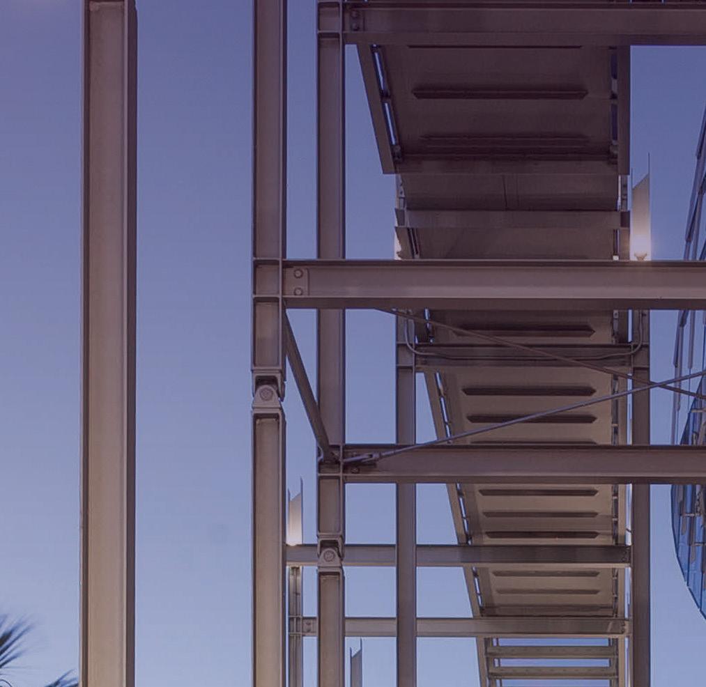
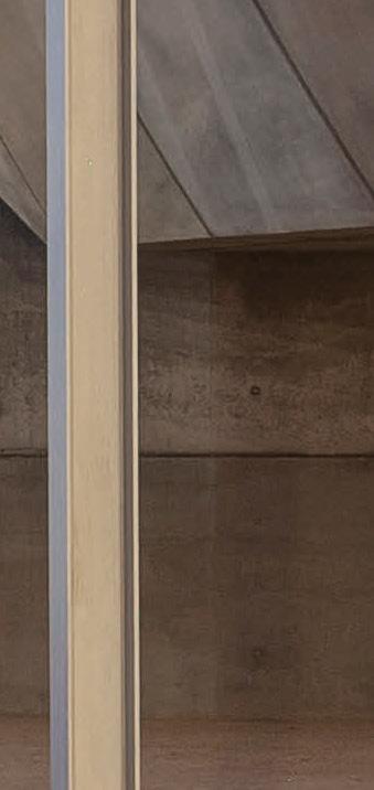
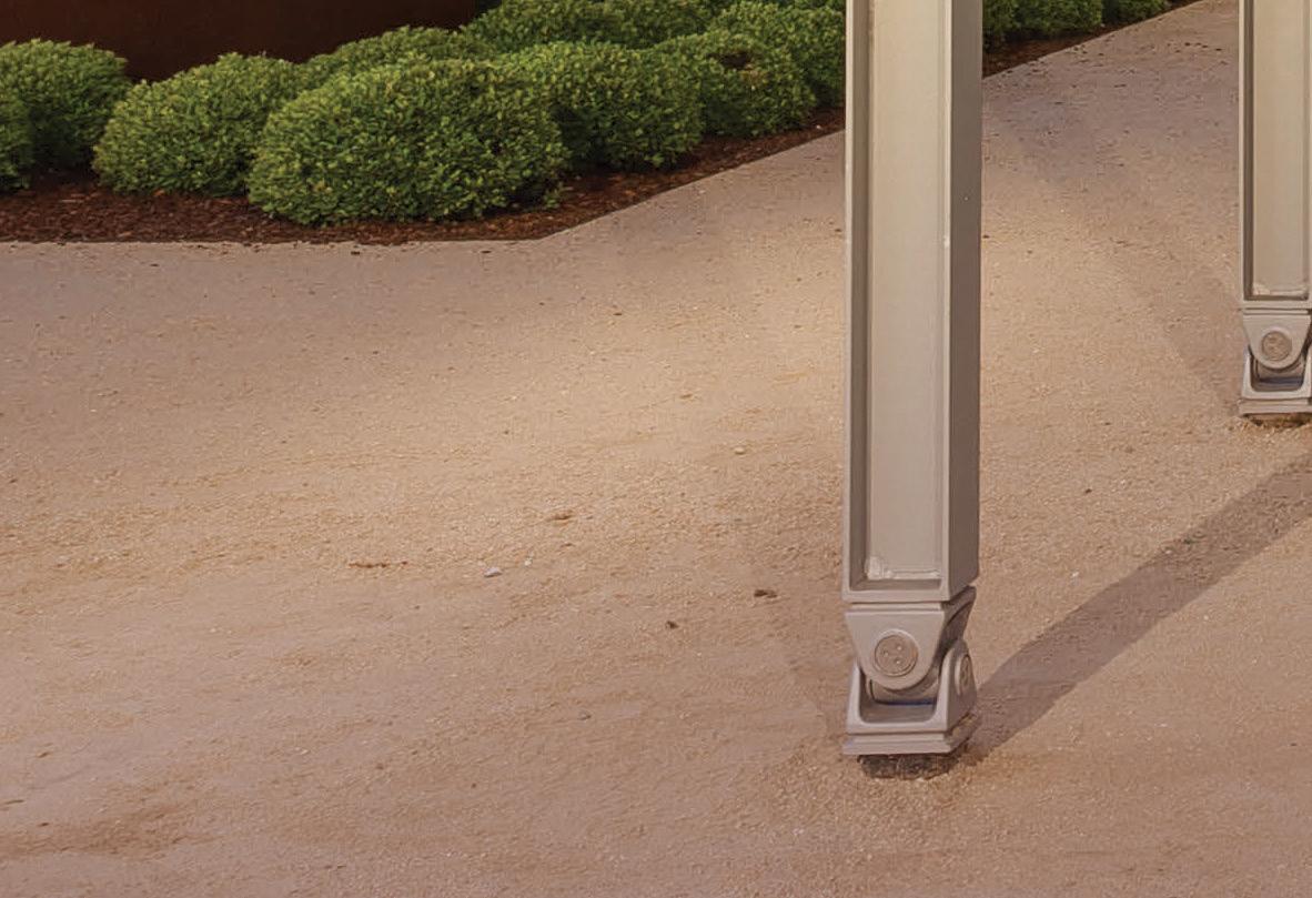
The Academy Museum of Motion Pictures was designed to celebrate the art and history of film. The museum is the largest museum in the United States dedicated to the arts and sciences of filmmaking. CAST CONNEX ® carried out industrial design, engineering, and supplied custom steel castings in the form of universal joint hinges and member end clevis connectors for use in the distinctive David Geffen Theater egress stair. The devices accommodate the significant differential movement between the base-isolated theatre structure and terra firma in the event of an earthquake.

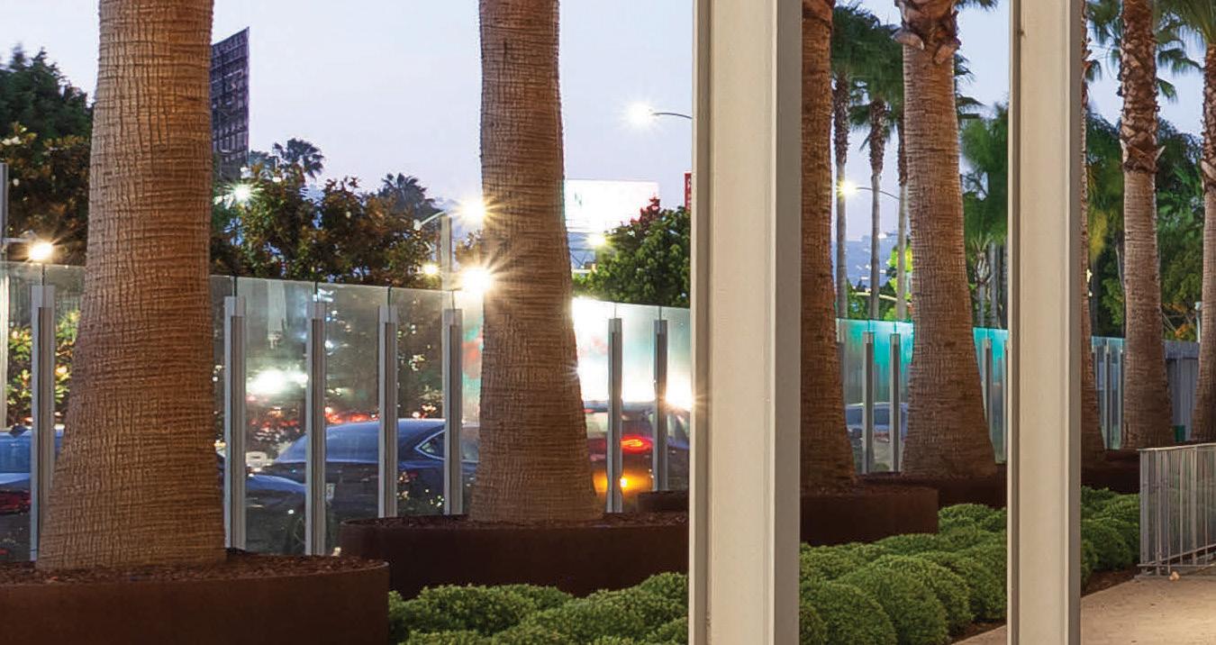
The result: structure enabling artistic expression.
Academy Museum of Motion Pictures, Los Angeles, CA
Architects: Renzo Piano Building Workshop with Gensler
Structural Engineers: BuroHappold Engineering


General Contractor: MATT Construction


Photography by Patrick Price
Freeform castings allow for flexible building and bridge geometry, enabling architects and engineers to realize their design ambitions.
Custom Cast Solutions simplify complex and repetitive connections and are ideal for architecturally exposed applications.




AGI Commerial
Anthony Forest Products Co.
ASDIP Structural Software

Atlas Tube
Cast Connex
Champion Fiberglass | Profile
Chicago Clamp Company | Profile
Computers & Structures, Inc | Profile
Concrete Reinforcing Steel Institute | Profile
Coughlin Porter Lundeen (CPL)
CTS Cement Manufacturing Corp | Profile
DuraFuse Frames
ENERCALC | Profile
Hohmann & Barnard, Inc.
ICC | Profile
IDEA StatiCa
Integrated Engineering Software, Inc.
Keller - North America
KPFF
MAPEI Corp.
Max USA Corp | Profile
National Ready Mix Concrete Assoc.
NCEES
NCSEA
New Millennium Building Systems
PCS-Structural
Portland Cement Association
PS=Ø | Profile
RISA Technologies
Simpson Strong-Tie | Profile
SSFM International
Structural Engineering Institute of ASCE
Tectonus
Williams Form Engineering
Statement of Ownership, Management, and Circulation (All Periodicals Publications Except Requester Publications)
Publication Title: STRUCTURE; 2) Publication Number: 1536-4283; 3) Filing Date: 9/23/21; 4) Issue Frequency: Monthly; 5)Number of issues Published Annually: 12; 6) Annual Subscription Price: $75-Domestic; $90-Canada; $135-International; 7)Complete Mailing Address of Known Office of Publication: 20 N. Wacker Drive, Suite 750, Chicago, IL 60606; Contact Person: Alfred Spada; Telephone: +1 (312) 649-4600; 8) Complete Mailing Address of Headquarters or General Business Office of Publisher (Not printer): 20 N. Wacker Drive, Suite 750, Chicago, IL 60606; 9) Full Names and Complete Mailing Addresses of: Publisher – Alfred Spada, 20 N. Wacker Drive, Suite 750, Chicago, IL 60606, Editor – Alfred Spada, 20 N. Wacker Drive, Suite 750, Chicago, IL 60606, and Managing Editor – Alfred Spada, 20 N. Wacker Drive, Suite 750, Chicago, IL 60606; 10) Owner: NCSEA Media, Inc., 20 N. Wacker Drive, Suite 750, Chicago, IL 60606; No individual owners; 11)Known Bondholders, Mortgagees, and Other Security Holders Owning or Holding I Percent or More of Total Amount of Bonds, Mortgages, or Other Securities: None; 12) Tax Status, N/A; 13) Publication Title: STRUCTURE magazine; 14) Issue Date for Circulation Data Below: September 2022; 15)Extent and Nature of Circulation. (Average No. Copies Each Issue During Preceding 12 Months, No. Copies of Single Issue Published Nearest to Filing Date); 15a) Total Number of Copies (Net press run): 27603, 27875; 15b) Paid Circulation (By mail and outside the mail) 1. Mailed Outside County Paid Subscriptions Stated on PS Form 3541: 26558, 26237; 2) Mailed In-County Paid Subscriptions Stated on PS Form 3541: 0, 0; 3. Paid Distribution Outside the Mails Including Sales Through Dealers and Carriers, Street Vendors, Counter Sales, and Other Paid or Requested Distribution Outside USPS: 0, 0; 4. Paid Distribution by Other Classes of Mail Through the USPS: 0, 0; 15c) Total Paid Distribution (Sum of 15b (I), (2), (3), and (4)): 26558, 26237; 15d) Free of Nominal Rate Distribution (By mail and outside the mail); 1. Free or Nominal Rate Outside-County Copies Included on PS Form 3541: 0, 0; 2. Free or Nominal Rate In-County Copies Included on PS Form 3541: 0, 0; 3. Free or Nominal Rate Copies Mailed at Other Classes Through the USPS: 0, 0; 4. Free or Nominal Rate Distribution Outside the Mail: 290, 272; 15e) Total Free or Nominal Rate Distribution [Sum of 15d (I), (2), (3) and (4)]: 266, 115; 15f) Total Distribution (Sum of 15c and 15e): 26848, 26509; 15g) Copies not Distributed: 755, 1366; 15h) Total (Sum of 15f and 15g,) 27603, 27875; 15i) Percent Paid(15c divided by 15f times 100): 99%, 99%; 16) Electronic Copy Circulation: None; 17) Publication of Statement of Ownership: Will be printed in the October 2022 Issue of this publication; 18) I certify that the statements made by me are correct and complete: Alfred Spada, Executive Editor
Director for Sales, Marketing & Business Development
Monica Shripka
Tel: 773-974-6561 monica.shripka@STRUCTUREmag.org
Executive Editor Alfred Spada aspada@ncsea.com
Publisher Christine M. Sloat, P.E. csloat@STRUCTUREmag.org
Associate Publisher Nikki Alger nalger@STRUCTUREmag.org
Creative Director Tara Smith graphics@STRUCTUREmag.org
Chair John A. Dal Pino, S.E. FTF Engineering, Inc., San Francisco, CA chair@STRUCTUREmag.org
Jeremy L. Achter, S.E., LEED AP ARW Engineers, Ogden, UT
Erin Conaway, P.E. AISC, Littleton, CO
Linda M. Kaplan, P.E. Pennoni, Pittsburgh, PA
Charles “Chuck” F. King, P.E. Urban Engineers of New York, New York, NY Nicholas Lang, P.E. Masonry Industry Representative
Jessica Mandrick, P.E., S.E., LEED AP Gilsanz Murray Steficek, LLP, New York, NY
Jason McCool, P.E. Robbins Engineering Consultants, Little Rock, AR Brian W. Miller Davis, CA
Evans Mountzouris, P.E. Retired, Milford, CT
John “Buddy” Showalter, P.E. International Code Council, Washington, DC
Eytan Solomon, P.E., LEED AP Silman, New York, NY
Jeannette M. Torrents, P.E., S.E., LEED AP JVA, Inc., Boulder, CO
STRUCTURE ® magazine (ISSN 1536 4283) is published monthly by The National Council of Structural Engineers Associations (a nonprofit Association), 20 N. Wacker Drive, Suite 750, Chicago, IL 60606 312.649.4600. Periodical postage paid at Chicago, Il, and at additional mailing offices. STRUCTURE magazine, Volume 29, Number 10, © 2022 by The National Council of Structural Engineers Associations, all rights reserved. Subscription services, back issues and subscription information tel: 312-649-4600, or write to STRUCTURE magazine Circulation, 20 N. Wacker Drive, Suite 750, Chicago, IL 60606.The publication is distributed to members of The National Council of Structural Engineers Associations through a resolution to its bylaws, and to members of CASE and SEI paid by each organization as nominal price subscription for its members as a benefit of their membership. Yearly Subscription in USA $75; $40 For Students; Canada $90; $60 for Canadian Students; Foreign $135, $90 for foreign students. Editorial Office: Send editorial mail to: STRUCTURE magazine, Attn: Editorial, 20 N. Wacker Drive, Suite 750, Chicago, IL 60606. POSTMASTER: Send Address changes to STRUCTURE magazine, 20 N. Wacker Drive, Suite 750, Chicago, IL 60606.
STRUCTURE is a registered trademark of the National Council of Structural Engineers Associations (NCSEA). Articles may not be reproduced in whole or in part without the written permission of the publisher.
The iconic Viaduct over the Los Angeles River has served as a backdrop for dozens of movies, TV shows, and more. There was a strong desire to create an equally impressive replacement structure. The new “Ribbon of Light” comprises efficient thin profiles made possible by a network of cables that support the bridge deck beneath. The design solution creates a striking structure via the repeated use of a concrete network of tied arches flowing seamlessly into supporting Y-Bent substructures.

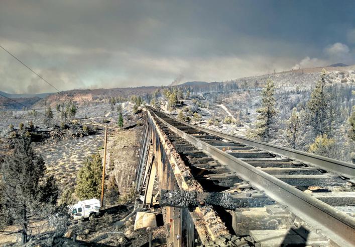
The 2021 Lava Fire heavily damaged multiple structures, including Union Pacific Railroad’s Dry Canyon Bridge near Weed, California. With 19 spans, the deck is a ballast deck with a timber ballast pan and curb. The superstructure consists of steel girders supported by steel bents. After the fire, nine spans needed to be replaced. The remaining ten spans were deemed salvageable through heat straightening.
 By Robert Graff, S.E., Damian Gronsky, P.E., and John Leventini, P.E.
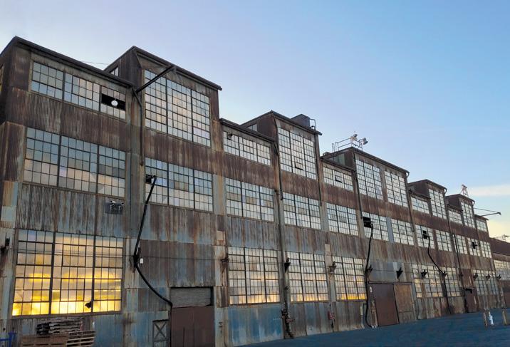
Building 12 was originally used for shipbuilding in WWII and, after the war, it was used to build the Bay Area Rapid Transit tunnels. Unfortunately, the building had fallen into disrepair in recent years. Sea level rise was a concern for the renovation project.
It was left to the general contractor and its engineering team to guide the project’s construction planning stage which included lifting the building.
article,
The David Rubenstein Forum at the University of Chicago is a 2-story podium and a 10-story tower of meeting rooms and social space neighborhoods. The structural system comprises a series of simple individual structural elements stacked to create desired open spaces efficiently. Incorporating post-tensioned concrete into the structural design was crucial to achieving the design’s long spans, cantilevers, and column-free spaces of up to 65 feet.
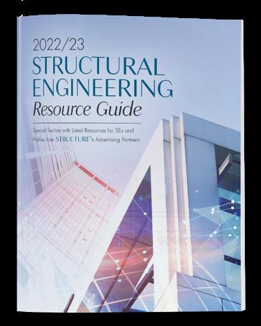
Annual Special Section with resources
structural engineers, including Profiles of some of STRUCTURE’s advertisers and categorized product listings.
Editorial Big Changes in SE Exam Are a Big Concern
By CASE Executive Committee
Structural Components Structural Thermal Breaks
By Alyson Hallander
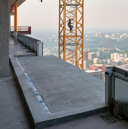
Structural Performance Blast Protection of Buildings
 By Donald Dusenberry, P.E.
Code Updates ASCE 7-22 Changes to Component and Cladding Wind Provisions By William L. Coulbourne, P.E., and Philip Line, P.E.
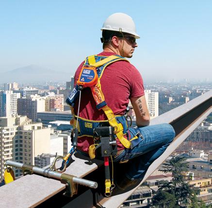
Structural Connections Fall Protection Anchorage Design Insights By Heidi Lopez-Hidalgo, P.E.
Structural Modeling Numerical Simulations of Bored Piles
By Hee Yang Ng, MIStructE, C.Eng., P.E.
Structural Design Horizontal Diaphragm Seismic Design
By Kelly Cobeen, S.E.
Just the FAQs FAQs on ASCE Standards

By Laura Champion, P.E., and Jennifer Goupil, P.E.
Pioneers in Engineering Dennis Nottingham
By Aaron Unterreiner
Historic Structures Rock Island Bridge 1856
By Frank Griggs, Jr., D.Eng., P.E.
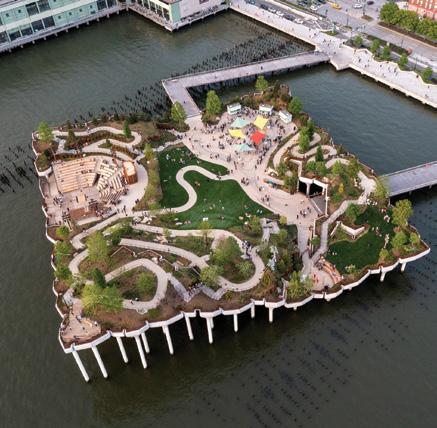
Spotlight The Little Island Pier
NCSEA Excellence in Engineering Award Winner
Index
News
Update CASE in Point






The National Council of Examiners for Engineering and Surveying (NCEES) intends to transition the SE Exam to a computerbased test (CBT). NCEES began the process of transitioning its licensing exams to a CBT format in 2011, and the SE exam is the last to undergo the change. Starting in 2024, the current two-section, 16-hour Structural Exam will be replaced with the new computerbased test. But here’s the rub: the new exam will be expanded to four sections and a length of 21 hours.

Although NCEES received significant input from the structural engineering community regarding the exam’s content, the format of the exam came as a surprise. CASE, through its participation, along with NCSEA and SEI, in the Structural Engineering Licensure Coalition (SELC), only became aware of the proposed format change following an April 2022 NCEES presentation to the SELC.
In a coordinated effort, representatives of CASE, SEI, NCSEA, and SELC attended the Structural Caucus at the NCEES Annual Summit in August. Mr. Jason Gamble, P.E., NCEES’ Chief Officer of Examinations, presented to the Caucus and answered questions. At press time, NCEES is still working out many of the key details of this new exam. Here is what we have learned about NCEES’ new CBT Structural Exam:
•As with the current exam format, there are vertical and lateral components. Each component has a breadth and depth section. 4 sections comprise the new examination, all of which must be passed. The current exam has two components with one section in each.
•The two breadth sections will consist of multiple-choice questions. For the exam reliability to be at the level NCEES desires, it will be longer by 5 questions – thus the increase in the number of questions and exam length – from 40 to 45 questions and from 8 hours to 11.
•The two depth sections will have five scenarios, each with 12 questions. On 4 of the 5 scenarios, 2 of the questions are pretest questions. The 5th scenario contains only pretest questions. Pretest questions do not count toward an applicant’s grade and will be used to create a bank of questions for future exams. The new depth exams total 10 hours of total depth versus 8 hours for the current depth exam.
•The breadth sections will be offered year-round. The depth sections will currently only be offered twice per year.
•With the current exam, a person can only pass vertical (breadth and depth) or lateral (breadth and depth) independently. With the new exam, a person can pass any of the 4 sections independently.
•All NCEES exams have seen a drop in the number of people taking exams where the transition was made to CBT. The expectation is that the new structural exam will see a similar decline in applicants.
So that’s the breakdown of the new exam. Here are our concerns:
•The greatly expanded length. The new CBT exam expands from 16 to 21 hours, and the number of testing days doubles from two to four. This affects test-takers and their employers in terms of lost time and productivity. NCEES has informed CASE that much of the new testing requirements – the extra questions, longer seat time, staggering of exam parts – are
driven by a reliability rating. Through SELC, CASE will continue to offer input to NCEES on the exam length issue, but to date, NCEES has not been very receptive to our feedback.
•Increased cost. SELC has been informed that the total exam cost will be $1400, versus $1000 for the current exam. However, a test taker will need at least two and possibly four separate trips to take the test. Travel, lodging, and meal expenses will at least double what they are currently. Companies will have to determine if they can afford to fund their employees’ SE licensing efforts.
• Will a longer exam process deter younger engineers from pursu ing SE licensure? The current structural exam is difficult, with pass rates below 40%, much lower than any of the other PE exams. Candidates will have to decide if the time required to pre pare for and take the exam is worth the effort. Some may forgo licensure. Others may choose another NCEES exam to gain licensure, despite their daily practice of structural engineering. Most states only require PE licensure for designing structures.

•Will a longer exam process blunt the decades-long state-bystate effort by our profession to promote separate licensure for structural engineering? One state licensing board representative has speculated that states may be less willing to pursue separate SE licensure based on a 4-day structural exam.
•Will this newly expanded exam act as a further barrier to entry into the structural engineering profession? Given the rigors of a 4-day exam (plus an 8-hour FE exam), students may choose a different engineering field – or a different major altogether. CASE strives to be the voice for the business and professional practice interests and concerns of structural engineering firms. The NCEES structural exam is a fundamental component for ensuring practitioners in our field are qualified to design the structures relied upon to sustain modern society. The importance of licensure for our profes sion is why we have taken to the editorial page to express our concerns. We welcome your input on this critical issue.
■
Kevin Chamberlain (kevinc@dcstructural.com) is the Chair, and Bruce Burt (bburt@rubyandassociates.com) Chair-Elect of the CASE Executive Committee.Structural thermal breaks prevent condensation and mold, reduce heat loss through envelope penetrations, lower energy costs and carbon emissions, and reduce owner liability – while meeting increasingly stringent building energy codes.
Reducing energy usage in buildings has become a focal point of the architectural, engineering, and construction (AEC) industry to meet national energy goals and reduce costs to building owners. Heating, ventilation, and air conditioning (HVAC) contribute significantly to total building energy use, leading designers to pursue strategies for achieving better thermal performance.
The industry has responded with improved efficiency of HVAC systems and strengthened building envelopes via increased wall insulation and high-performance windows and doors. However, significant heat energy transmission through steel and concrete thermal bridges penetrating the envelope of otherwise well-insulated buildings is often overlooked.
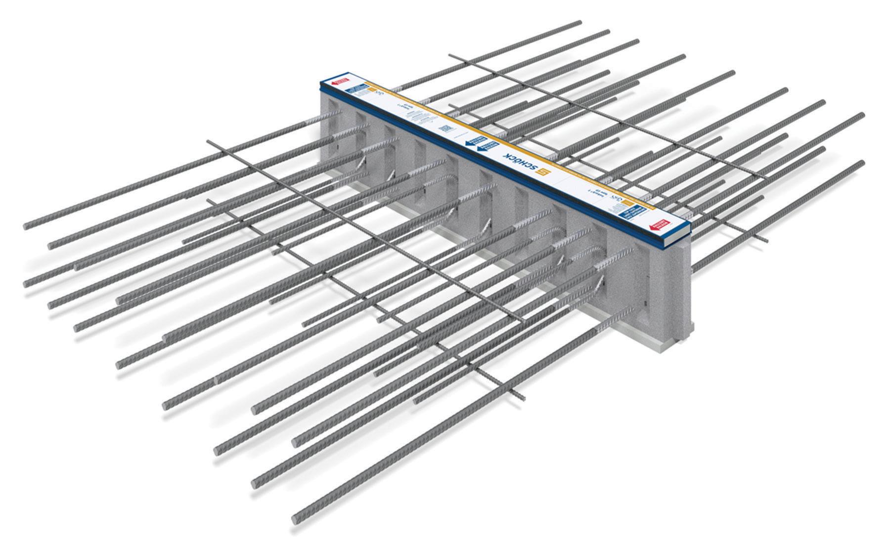
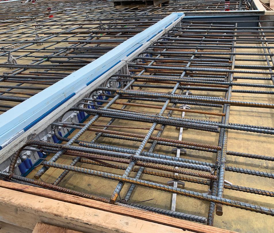
Figure 1. Concrete-to-concrete structural thermal break consists of tension (straight) and shear force (curved) bars penetrating the insulation block and tying to the interior and exterior slab reinforcement.
to improve energy efficiency by various means, including incorporat ing structural thermal breaks to strengthen the building envelope.
That is changing as revised building energy codes directly address thermal bridging. An addendum to the American Society of Heating, Refrigeration, and Air Conditioning Engineers’ ASHRAE 90.1-2019, Energy Standards for Buildings Except Low-Rise Residential Buildings, specifically addressing thermal bridging and structural thermal breaks, is currently under review – a prelude to possible inclusion in future editions.
In 2020, New York City and Seattle became the first cities in the United States to mandate the mitigation of thermal bridging at concrete penetrations through the building envelope. In addition, major utilities offer financial incentives for builders and developers
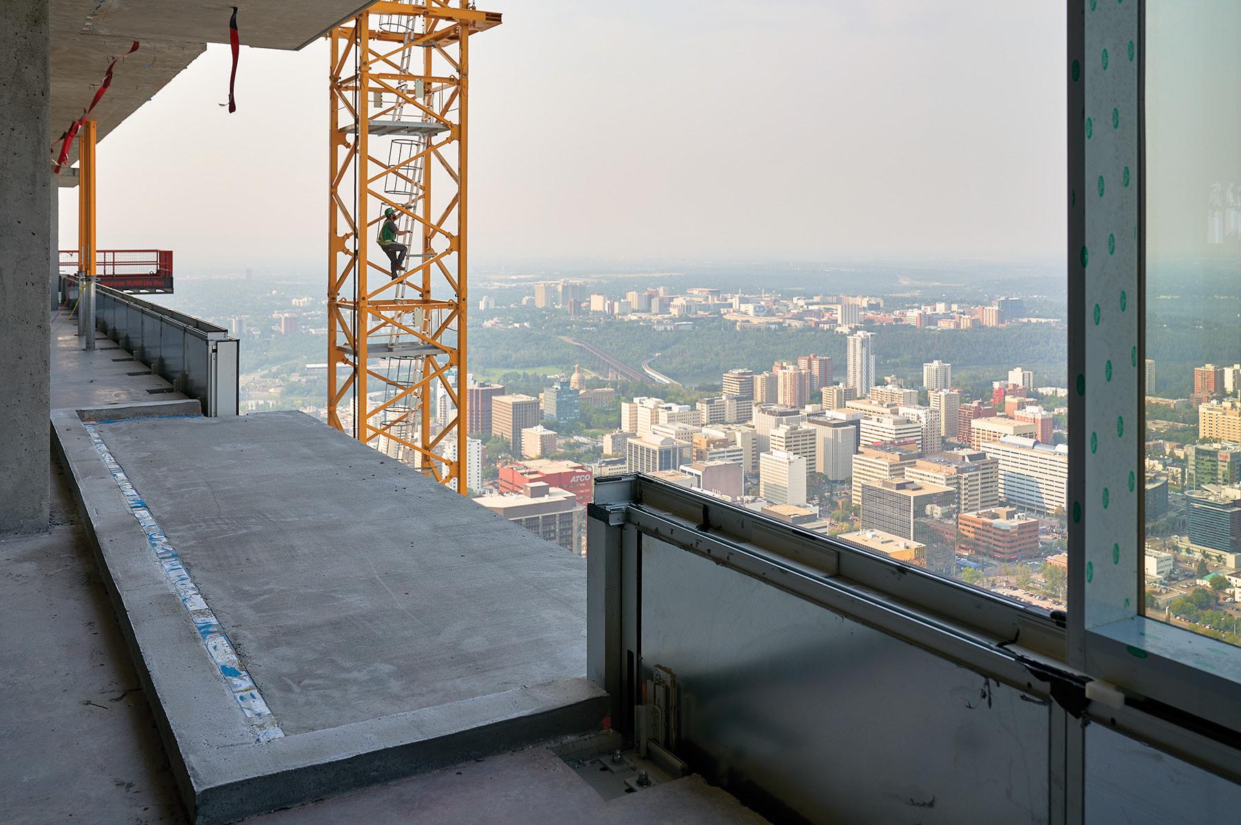
The thermal conductivity of structural steel at beams, canopies, rooftop connections, and concrete that comprises a conventional pour-through balcony, for example, allows the rapid dissipation of interior heat into the exterior. The resulting energy waste can be minimized by installing structural thermal breaks at the building envelope between the interior slab or steel beam and the cantilevered or supported exterior structure. In addition, the risk of the interior structure near the thermal bridge reaching the dew point – which creates an ideal environment for condensation and mold growth – is eliminated.
Structural thermal breaks perform two functions:
1) To minimize the transfer of heat across thermal bridges that penetrate the building envelope, and 2) To maintain the structural integrity of the thermally broken connection and transfer loads between the interior and exterior structural elements.
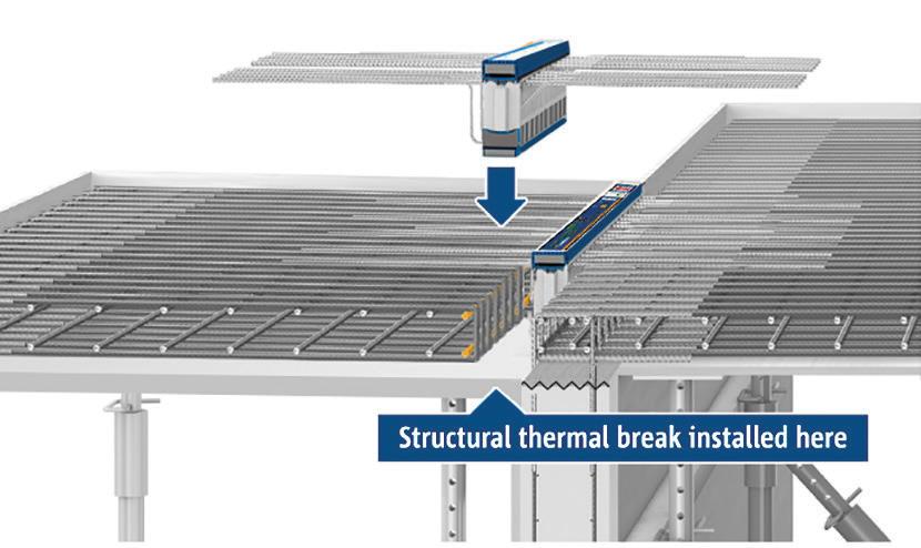
For concrete applications, manufactured structural thermal break modules (Figure 1) are constructed of polystyrene foam which is approximately 98 percent less conductive than concrete, and stainless steel rebar, which is approximately 67 percent less conductive than carbon steel rebar, reducing heat energy losses through balconies by up to 90 percent. Similar energy savings can be realized at slab edges, parapets, and other concrete envelope penetrations using structural thermal breaks (Figure 2).
Figure 2. Concrete-to-concrete structural thermal breaks installed.
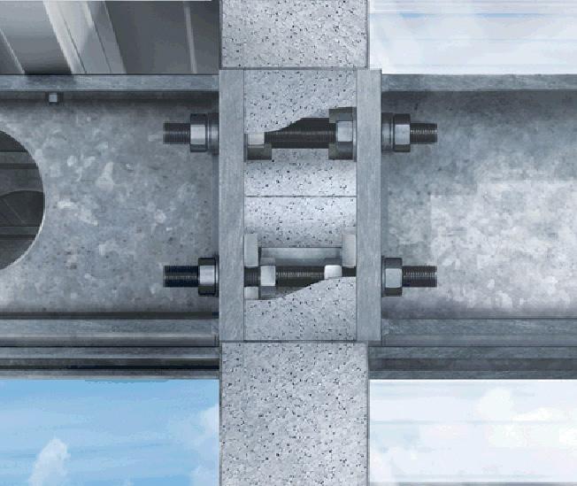
For steel applications, structural thermal break connections (Figures 3a and 3b) are comprised of insulated stainless steel modules and insulation fillers secured between steel end plates. The placement of the engineered structural thermal break between the endplates of the interior and exterior
steel structure minimizes the conductive surface area, with only the load-bearing stainless steel bolts and HSS block of the structural module crossing the insulating layer. Again, the stainless steel rods conduct two-thirds less thermal energy than equivalent structural steel components.
As an alternative to a manufactured structural thermal break prod uct for steel connections, bolted connections with thermal pads are often used to create a thermal break. For the pad connection to be effective, the pad material needs to be thick enough to break the thermal transfer – at least 1 to 3 inches (38 to 76 millimeters). Further, suppose the bolts are of structural steel rather than less conductive stainless steel. In that case, the net result may show little improvement or be worse than an unmitigated continuous beam through the building envelope. A benefit of thermal pads is that the pad material is inexpensive. The downside is that once the pad thickness increases to a level where it is thermally effective, the shear strength of the connection drops dramatically, requiring additional bolts and impacting thermal conductivity through the connection. In addition, there is the potential for degradation in the pad material and the potential risk of condensation.

One issue resulting from thermal bridging is compromised occupant comfort. In a typical apartment where the balcony slab creates a thermal bridge, thermal imaging shows the cold creeping into the heated space, making the adjacent interior floors much colder than the rest of the floor. For example, an outside temperature of 32°F (0°C) and an interior temperature of 70°F (21°C) bring the temperature immediately next to the balcony door to a chilly 52°F (11°C). Cold floors and sur rounding surfaces make a space less comfortable, which often means occupants bump up the thermostat to compensate.
Cold surfaces resulting from thermal bridging also lead to condensation buildup on interior surfaces. In modern construction using vapor bar riers, the relative humidity of interior spaces during cold winter months ranges from 30 to 50%, versus approximately 25% in older buildings without
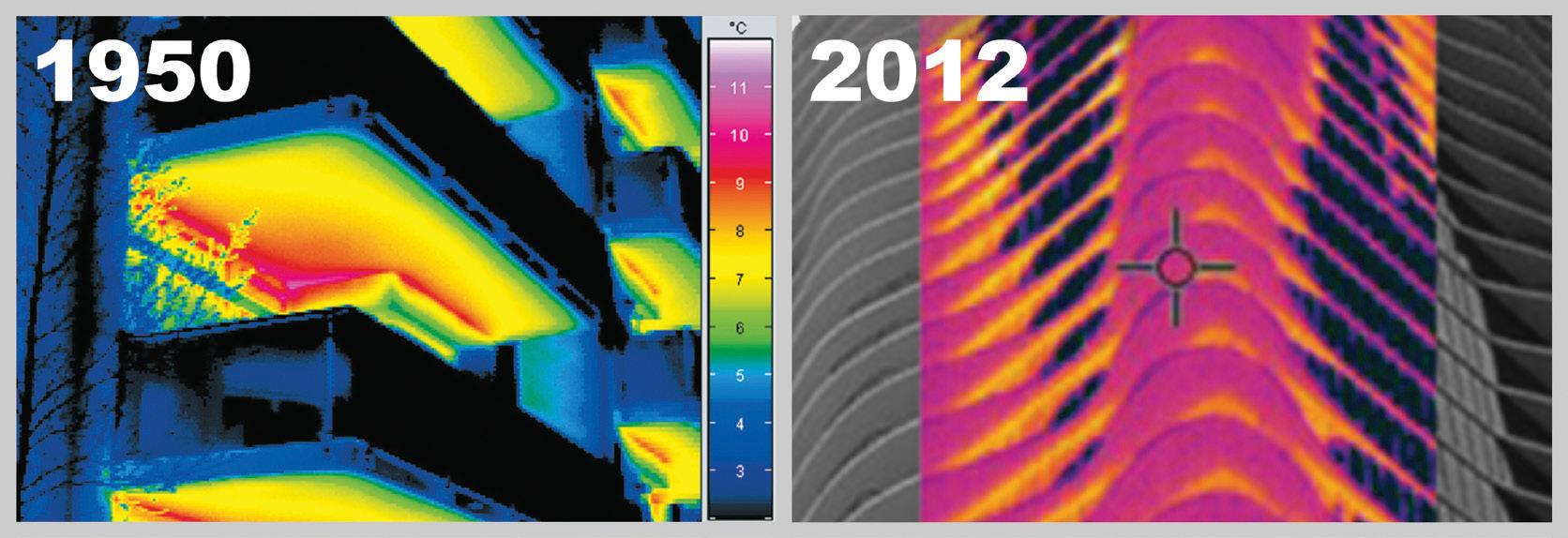
vapor barriers. As a result, interior surfaces adjacent to thermally unbroken connec tions can cool to the dew point, causing condensation and sup porting mold growth. In turn, this can damage the interior structure and finished surfaces and adversely affect air quality and occupants’ health, exposing the owner to liability. The third issue resulting from thermal bridging is significant heat loss. Thermographic images in Figure 4 show the effects of uninsulated thermal bridges on heat loss, comparing a typical building from the 1950s (left) to a more recent structure. Modern insulation efficiency has improved, yet unin sulated thermal bridges such as those found at balconies continue to be the path of least resistance for heat transfer. Thermal bridges significantly detract from the thermal performance of the surrounding insulated wall assemblies and can act as cooling fins to dissipate heat from the warm interior structure into the exterior environment.
Breaking the heat transfer pathway by incorporating a structural thermal break prevents cold surfaces from being introduced into the heated spaces, ensuring that thermal comfort is maintained and eliminating the risk of condensation and mold growth on interior surfaces. Also, a thermal break reduces heat loss through the insulated building envelope.
Structural thermal breaks have been designed for a wide range of con crete and steel structural connections and structural load conditions. In addition to balconies, structural thermal breaks can be incorporated at parapets, exposed slab edges, canopies, columns, concrete walls, and rooftop connections for mechanical equipment.
Concrete structural thermal breaks are manufactured in various heights to accommodate slab depth and, with various configurations of the steel reinforcement, to transmit bending moment and vertical shear forces. For buildings in seismic regions, supplemental modules that withstand lateral forces work in conjunction with those designed for bending moment and vertical shear.
Steel structural thermal break modules are used to resist compression, tension, and shear forces. Modules acting together in tandem resist moment forces for a cantilevered beam connection.
When incorporating structural thermal breaks into a building project in North America, the manufacturer is responsible for designing the thermal break connections. The project structural engineer should ensure that the structure surrounding the connection is designed to receive the loads transmitted by the structural thermal break adequately.
In addition to design services, manufacturers commonly provide resources for ensuring a seamless design and installation process, including CAD/BIM details and models, specifications, continuing education courses, and case studies.
Installing structural thermal breaks for concrete applications is simple (Figures 5a and 5b). For example, for a mild reinforced concrete condition, the installers typically construct the interior rebar cage, leave a seven-inch gap, then construct the exterior rebar cage. The structural thermal breaks are placed in the gap, end to end, and tied into the rebar cages on each side. The team can then proceed with one continuous concrete pour of the interior and exterior slabs.
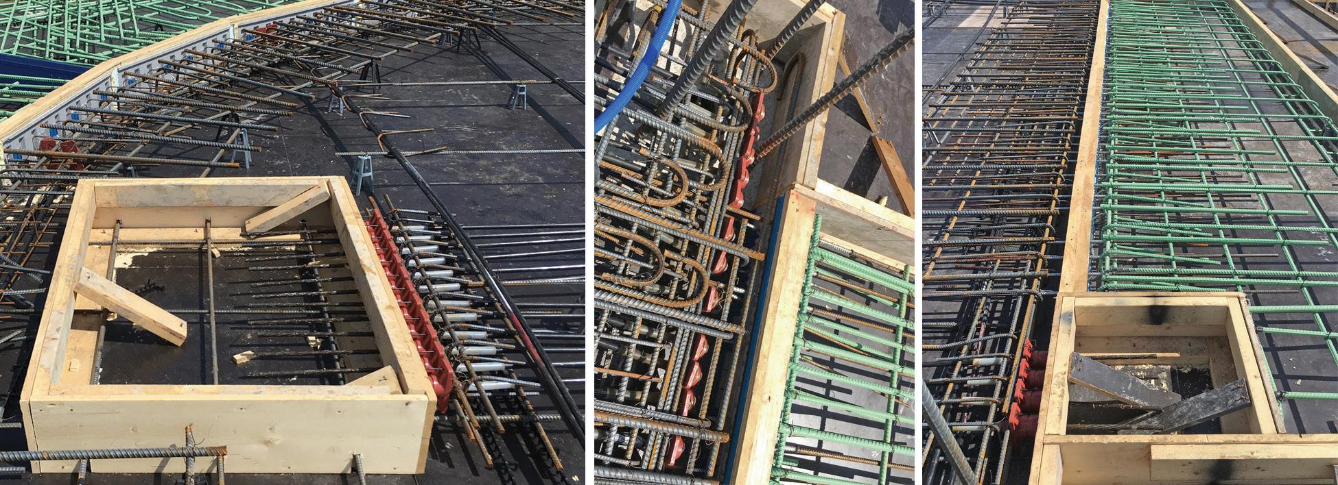
Using structural thermal breaks with post-tensioned (PT) slabs is also possible with some advanced planning regarding the placement of the PT tendons. Figure 6 shows one PT layout design method
to avoid intersecting the structural thermal breaks. A small box is isolated for accessing the live ends. After tensioning, rigid insulation is placed continuously with the adjacent structural thermal breaks, and the box is filled with high-performance grout.
Structural thermal breaks can also be installed into precast concrete applications.
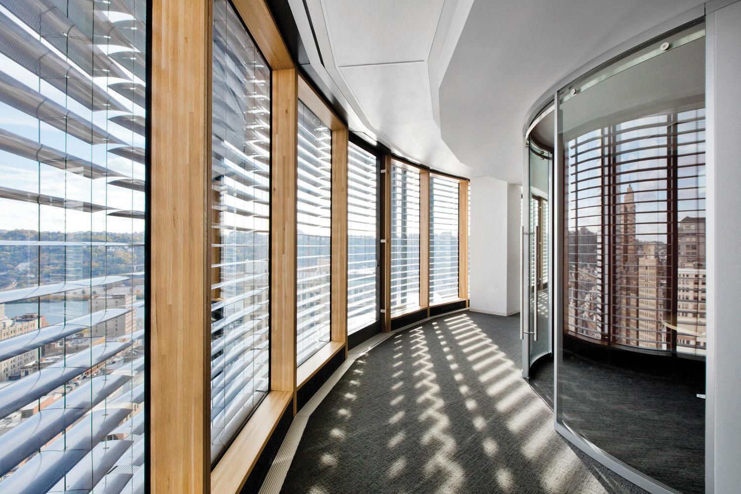
The 33-story LEED Platinum Tower at PNC Plaza (Pittsburgh, PA) has been touted as the “world’s greenest office tower.” It was designed to consume about half the energy of conventional structures of equivalent size, thanks mainly to a ventilation system that takes advantage of seasonal temperatures when advantageous and insulates against them when not.
The key element of the energy-saving system is a double-skin façade consisting of an interior and an exterior glass curtain wall (Figure 7 ). For nearly half of the year, during spring and fall, the building ventilates as fresh air flows through actuated vents in the exterior façade into the space between the curtain walls and through two vertical thermal shafts and a solar chimney, warming or cooling the interior space passively. During summer and winter, the building reverts to conventional mechanical heating/cooling, requiring continuous insulation of the
interior façade wall, including thermally break ing the concrete slab extensions supporting the exterior façade wall.
The design team specified Schöck Isokorb® con crete-to-concrete structural thermal breaks for the cantilevered concrete slabs. There is one mile of these thermal breaks on 30 floors, installed linearly along the junction of the inner curtain wall and building core.
Benedict Tranel, Principal at Gensler Architects and Project Architect on the Tower, says, “The inner façade of the building is like the insulation layer in a jacket while the out side glass façade is like the outer GORE-TEX® fabric layer.” Hao Ko, design director of Gensler Architects, adds, “Without the thermal breaks, it would be like wearing a down jacket but leaving it unzipped.”
The Tower has won the R&D Award for High-Performance Buildings, received LEED Platinum certification, and set a new benchmark for energy efficiency and sustainability.

In Minneapolis, the U.S. Bank Stadium wows visitors with its striking asymmetrical shape, transparent roof, acres of glass, 95-foothigh (30 meters) pivoting glass doors, and an enormous asymmetrical video board (Figure 8).
The unconventionally large and heavy video board is supported by structural steel tubes cantilevered from the steel frame work within the heated building envelope. Sitting 150 feet (45 meters) above grade on the exterior of the western prow, the behemoth board weighs 45,000 pounds (20,400 kilograms).
The challenge was the thermal conductiv ity of the structural steel supporting the board. The board connects to an exterior metal panel, behind which sits an array of metal studs with an insulated water proofing barrier – all surrounded by a steel superstructure. The high thermal conduc tivity of steel increases thermal bridging between Minnesota winters’ sub-zero temperatures and the supporting steel work’s heated interior. “It was imperative to prevent cold exterior steel from touching warm interior steel and causing a thermal bridge,” said Eric Grusenmeyer, Project Engineer at Thornton Tomasetti.
from becoming cold, reaching dew point, and forming condensa tion, which could compromise the surrounding structure and incur ongoing maintenance costs.
According to Lance Evans, Principal and Senior Vice President for the architectural firm HKS, which designed the stadium and board, “Our design had to address severe Minnesota weather conditions. Outside temperatures can dip to more than 20 degrees below zero, while the stadium must maintain a com fortable temperature for the people inside. Preventing thermal bridging was essential to ensuring the integrity and performance of the stadium structure. The structural thermal breaks provided an effective barrier to accomplish that task.”
Concrete and steel structures penetrating the insulated building envelope provide a conductive pathway for interior heat energy to dissipate into cold exterior environ ments, adversely affecting owners, tenants, and the environment.

Figure 8. Steel-to-steel thermal breaks prevent thermal bridging where the video board’s support structure penetrates the building envelope. Courtesy of Minnesota Sports Facility Authority.
The design team specified Isokorb structural thermal breaks for steel-to-steel construction. The thermal break products are equipped with flanges and bolts for fastening to flanged rectangular steel tubes on the interior side and to opposing flanged steel tubes supporting the video board on the exterior side.
The resulting assembly reduces heat loss through the penetra tion by up to 50%, reducing heat energy costs and heating system capacity requirements accordingly. Most importantly for the video board application, they prevent the interior side of the supports
Thermal breaks installed at the building envelope maintain the structural integrity of steel and concrete penetrations while reducing the escape of heat energy by up to 50 and 90 percent, respectively, preventing interior condensation and mold, improving the comfort of occupants, complying with stringent building codes, and contributing significantly to sustainability goals. ■
References are included in the PDF version of the online article at STRUCTUREmag.org
As Product Engineer for Schöck North America, Alyson Hallander leads the company’s educational efforts to grow awareness of structural thermal break solutions within the AEC industry.


The events of 9/11 changed many owners’ perceptions of the risk to their facilities. Their fear of malicious threats thrust practicing structural engineers into an unfamiliar role. As a result, structural engineers needed to learn how to quantify and analyze for blast effects as they assisted their private clients with the evaluation of threats to their facilities and the means to provide prudent, reasonable, and effective resis tance. In response, the Structural Engineering Institute (SEI) of the American Society of Civil Engineers (ASCE) developed a new standard, ASCE/SEI 59 Blast Protection of Buildings (ASCE 2011), describing how engineers could design blast resistance into structures.
The original edition of ASCE/SEI 59, released in 2011, was the first authoritative standard intended for use by engineers designing private sector facilities. It is a voluntary document that provides the minimum requirements for planning, design, construction, and assessment of new and existing buildings when subjected to the effects of accidental or intentional explosions. It is written in mandatory language to be referenced in contracts for engineering services or adopted by regulatory agencies. Publication of the first revision to this standard is expected in late 2022 or early 2023.
The committee that developed and revised ASCE/SEI 59 drew from authoritative references, some of which were developed for the defense of government facilities, to prepare a comprehensive docu ment containing the essential relevant information. It defaults to a practical design approach suitable for the prudent and somewhat conservative design of most buildings with conventional, regular framing systems and typical occupancies. Beyond this default pro cedure, the standard also allows for alternatives running up to the most sophisticated analytical approaches to encourage economical and innovative designs. As with most standards developed by SEI, a Commentary section provides background information and suggested application approaches and includes references and interpretations explaining the Provisions.
The first chapter describes the general provi sions relevant to the standard, beginning with a statement of the scope of the standard. It states: “This voluntary standard provides minimum planning, design, construction, and assessment requirements for new and existing buildings subject to the effects of individual accidental or malicious explosions, including principles for establishing appropriate threat parameters, levels of protection, loadings, analysis method ologies, materials, detailing, and test procedures. However, this standard is not applicable for the mitigation of multiple explosions, intentional explosions such as weapons testing, or potential accidents involving ammunition or explosives during their develop ment, manufacturing, testing, production, transportation, handling, storage, maintenance, modification, inspection, demilitarization, or disposal.”
The first chapter also includes the definitions and symbols common to all sections. It concludes with the important issues of user qualifica tions, information sensitivity, and a section listing other standards and reference documents.
The second chapter, on design considerations, covers security evaluation, security planning, and risk assessment. The risk assessment includes an analysis of the threat, the vulnerabilities, and the consequences. Given that structural design is just one way to minimize the outcome of an explosion, this chapter advocates for considering threat reduc tion, vulnerability reduction, and consequence reduction as part of the process of improving protection. In any event, one must acknowledge that some risk must be accepted inherently since designers and owners usually do not have complete control over events that threaten build ings, particularly when malevolent intent is involved.
The third chapter deals with performance objectives, building clas sification, and levels of protection. Primary goals include limiting the potential for structural collapse, maintaining the building envelope to protect persons and other assets inside a building, and minimizing flying debris that could induce localized damage. Recognizing that different facilities require different performance levels, the standard defines four levels of protection with the performance goals listed in the Table. Response limits for flexural and compression elements are calibrated to these levels to guide the user when determining the acceptability of a design.
Since the very rapid strain rates normally induced by impulsive blast loads lead to yield stresses and failure stresses that often are higher than for static loads, the standard includes strength increase factors that can be considered when judging performance.
Chapter 4
The fourth chapter provides loading functions. It draws on research performed for government facilities, providing simplified procedures for external and internal explosions.
The basic procedure for external blast requires converting the design-base assumption about the explosive material and weight to an equivalent quantity of trinitrotoluene (TNT). The standard states peak overpressures and impulses for the equivalent quantity of TNT, considering the distance from the blast to the structure. Overpressures and impulses for the design of blast-facing surfaces include reflection coefficients that are functions of the angle of incidence of the shock front. The shock front loading is then idealized as an instantaneously applied triangular pulse in which the peak reflected pressure at the start and the total impulse magnitude over the duration are the same as the actual loading. Next, the peak dynamic pressure and its clearing time are calculated, and the corresponding loading is idealized as a triangular loading function. Finally, the two are combined, creating a bilinear loading function. Alternatively, just the shock front loading may be used if it has a lesser impulse. Also, a negative loading phase may be included if it is critical.
In the basic procedure for an internal blast, the shock loading is calculated as for an external blast. Then, the peak gas overpressure is determined from the quantity of TNT simply and conservatively from the interior free volume and the vent area.

Since this approach for internal explosions can be very conservative, the standard allows for more sophisticated approaches using recognized literature.
These simplified approaches for external and internal explosions are often adequate for designing most structural forms subjected to explosions commonly assumed for protective design. However, the user is directed to other references that provide sophisticated methodologies for determining blast effects and structural performance for unusual circumstances. Of course, approaches that are more sophisticated than those provided as the default in ASCE/SEI 59 are allowed even for common scenarios, should the owner and the blast consultant wish to refine the design approach.
The provisions in the original edition of ASCE/SEI 59 contained limited information about the effects of bomb fragments (primary fragments) and site debris (secondary fragments) impact on structures. However, detailed information about these blast effects was published in the Commentary, recognizing that the most common blast design of commercial buildings does not consider fragmentation.
The sixth chapter describes methods and limitations for analyzing and designing structural elements and systems. It outlines analysis concepts, advanced analysis,
blast design, modeling, materials, member and connection detailing, and touches on disproportionate collapse. Specified analysis methods include pressure-impulse charts (pre-determined, plotted element response as a function of peak pressure and impulse), lumped parameter models (single degree of freedom and multi-degree-of-freedom dynamic systems), and finite element dynamic models.
The seventh chapter provides guidance for isolating areas within a structure. The intent is to guide designs to protect occupants of a building from an interior blast in a specific location, such as a lobby, protect egress components, and design a safe haven where occupants can retreat within a building when a threat is made.
The eighth chapter describes processes for hardening the exterior envelope to protect the structure, occupants, and other assets. In addition to addressing exterior walls, this chapter provides guidance for the design and function of windows and exterior doors. This chapter addresses concrete, masonry, metal wall and window systems, and flat slab, metal deck, composite steel-concrete, and steel joist roof systems.
The ninth chapter specifies when to use and how to modify existing consensus materials standards for design, detailing, and construction to resist blast effects. When appropriate, the standard provides modifications for reinforced concrete and steel columns, beams, and floor and roof systems.


Design to resist explosions often requires novel structural systems and evaluation of distortions well into the inelastic range using sophisticated software. Sometimes performance of systems and components that resist blast effects is verified by testing. The tenth chapter provides guidance for validating the suitability of design tools and methodologies and structural constructions for blast resistance when conventional approaches for common environmental loads do not suffice.
Often, and certainly for unusual and critical applications, designs should be reviewed by an independent team of registered design professionals. e tenth chapter discusses the need for peer reviews and outlines the qualifications of the reviewers.
e committee that maintains ASCE/SEI 59 embarked on a review and revision cycle a few years ago. is review revealed that terms such as “element,” “component,” and “member” were not used consistently throughout the document. is could cause confusion when applying the provisions in the standard because it was not always clear to what portion of a structure some provisions applied. To add clarity, new definitions have been added for these terms and others, and text throughout has been updated to be consistent with the new definitions. For instance, the standard now defines these example terms as: Component: Part of an architectural, mechanical, electrical, or structural system of a building.
Element: Assembly of structural components that act together in resisting forces, including gravity frames, moment-resisting frames, braced frames, shear walls, and diaphragms.
Member: Individual structural component that acts to resist forces, including columns, load-bearing walls, girders, beams, braces, struts, girts, purlins, joists, slabs, and decks.

e suitability of a design for blast resistance is verified by, among other means, comparing the blast-induced member forces to their remaining capacity after accounting for environmental loads acting simultaneously with a blast. In the original edition of ASCE/SEI 59, this available strength was evaluated using two formulas derived from the extraordinary events load combinations found in ASCE/ SEI 7 Minimum Design Loads for Buildings and Other Structures (ASCE 2005). One of those load combinations included point-in-time snow load and the other included point-in-time wind load. e load
combination involving wind has been removed in the new edition of ASCE/SEI 59, following changes implemented in the 2016 edition of ASCE/SEI 7 (ASCE 2016).
Fragmentation is covered in much more detail in updated Chapter 5. While the original edition of ASCE/SEI 59 relegated analyses and design requirements to the Commentary, the new edition brings a simplified procedure for secondary fragments into the Provisions. Now the standard advocates for anchoring bulky site features against blast effects or, absent that, analyzing the impulse that propels unanchored features and the corresponding velocity. Chapter 5 now also contains simplified procedures to evaluate the potential for scabbing of concrete and masonry walls subjected to secondary fragment impact.
In the section of Chapter 6 dealing with the modeling of members, the revised standard acknowledges that foundation members are permitted to settle and move laterally in response to blast effects. However, despite that, the foundations must be designed to the same performance criteria as the walls they support, and the structure above must remain stable should foundations move.

Chapter 6 also clarifies that roof structures that act as diaphragms and contribute to the structure’s overall stability must be treated as part of the lateral load resisting system.
In the original edition of ASCE/SEI 59, glazing could be designed using static procedures for medium and lower levels of protection. In the revised edition, the section of Chapter 8 dealing with blastmitigating window systems allows static procedures to determine the capacity of glazing but requires dynamic analyses or full-scale dynamic testing to demonstrate that window systems meet the expectations of the required level of protection.
Connections and anchorages for window systems are required to have ultimate strength that equals at least 150% of frame and mullion strengths. However, in the revised edition, energy dissipating systems, such as energy-absorbing anchors, are allowed to reduce blast forces on surrounding walls. e performance of those energy-dissipating systems must be demonstrated through explosive or shock tube testing or detailed analytical models that have been validated with test data.
e standard’s original edition required oversized and metal rollup doors to meet the same performance criteria as common doors. In the revised standard, oversize and rollup doors that do not meet performance criteria for common doors may be used if they are augmented with a debris-mitigating catch system.
Chapter 8 of the original edition required pretensioned and post-tensioned concrete
panels to have straight tendons for resistance in both directions to account for rebound. is requirement is removed in the revised edition, provided the reinforcing steel needed for blast resistance is mild steel.
e Provisions and the Commentary of Chapter 9, dealing with materials detailing, are substantially revised in the updated edition of ASCE/SEI 59. A few examples of the changes are summarized below.
e original version of Chapter 9 prohibited the use of lightweight concrete in blast-resistant structures unless tests or rational analyses demonstrated that the lightweight concrete could satisfy the performance criteria of the standard. In the revised edition, lightweight concrete is permitted without restriction beyond limiting its maximum strength to 5,000 psi and requiring that design for blast resistance not violate conventional requirements for lightweight concrete.
e requirements for concrete slabs and walls are updated in the revised standard. For instance, reinforcing steel splices in slabs are required to be near supports and may be class B tension splices, mechanical splices, or welded connections. In addition, minimum reinforcing steel ratios are eliminated for concrete walls.

Structural steel used in blast-resistant design is limited in strength to 50 ksi in the revised standard. Plates 2 inches thick in built-up members must meet prescribed Charpy V-notch requirements. In the revised standard, structural steel connections must have ductile failure modes or be designed for 130% of the forces associated with the ultimate flexural capacity of the supported members unless they are designed based on the results of nonlinear dynamic analyses. In that case, connections must be designed for 150% of the calculated forces.
e requirements for welded connections in structural steel have been updated substantially. Now there are new requirements for weld configuration and filler metal. Testing and inspection requirements are expanded. e standard now advocates for short-slotted holes oriented perpendicular to the direction of service force in shear connections where possible.
A new section is added in Chapter 9 to cover the requirements for open web joists. Among other provisions, the revised standard requires the bottom chord of open web joists subjected to downward loads to yield before failure of the top chord and webs while considering that the blast load is applied as a transverse load along the top chord. In addition, joist seats and their connections must be designed for the flexural strength of the joist. Alternatively, joists can be designed for 150% of the calculated loads when performance remains elastic.

New sections are added for composite steel and concrete columns (steel tubes filled with concrete) and steel plate composite walls (concrete cores with steel faceplates).
e fiber-reinforced polymer composite section is updated substantially. Limitations are added for the static strength of resin and its adhesion to the substrate, imposing pull-off failures to be controlled by the strength of the substrate.
e revision of ASCE/SEI 59 represents a modest update of this critical standard. e committee’s goal was to add clarity and expand guidance when appropriate, based on feedback and experience gained through the use of the original edition. Given that this article has been prepared while the process to revise this standard is nearing completion, its contents are still subject to change up to final printing. Please visit ASCE’s website (www.asce.org) for information about the status of the standard and to purchase the latest edition once it is complete.■
References are included in the PDF version of the online article at STRUCTUREmag.org.



OVER 990 pages and
unique Design Guide assists in
worked-out
proper
edition of Building Code
for
concrete
Revised Component and Cladding (C&C) wind load provisions in ASCE 7-22, Minimum Design Loads and Associated Criteria for Buildings and Other Structures, produce in most cases either the same or slightly lower pressures than would occur under the prior edition while also preserving the extensive wind tunnel testing basis of the ASCE 7-16 C&C wind provisions.
The C&C wind load provisions adopted for ASCE 7-16 introduced several changes that increased the C&C wind pressures in some roof zones of flat, gable, and hip roofs. Roof zones were added, usually increasing the number of zones from 3 to 6. There were some zones where the effective wind areas (EWA) were reduced to less than 10 square feet, thus increasing the C&C pressures. Hip roofs had two sets of graphs for EWA vs. (GCp) pressure coefficients, one for h/B ≥ 0.8 and one for h/B ≤ 0.5, with interpolation required between these two h/B values. Finally, for hip roofs with a slope between 27° and 45°, determining the (GCp) value required using an equation that used the roof slope. While based on wind tunnel testing, the determination of (GCp) coefficients became more complicated in ASCE 7-16, and an
increase in some pressures based on small EWA was not supported by the ‘science’ of load sharing between the C&C elements.
The primary changes to ASCE 7-22 Chapter 30 C&C wind loads provisions are:
1) Reduced the number of roof zones on both gable and hip roofs to three
2) Changed the EWA vs. (GCp) graphs such that the smallest EWA is not less than 10 square feet
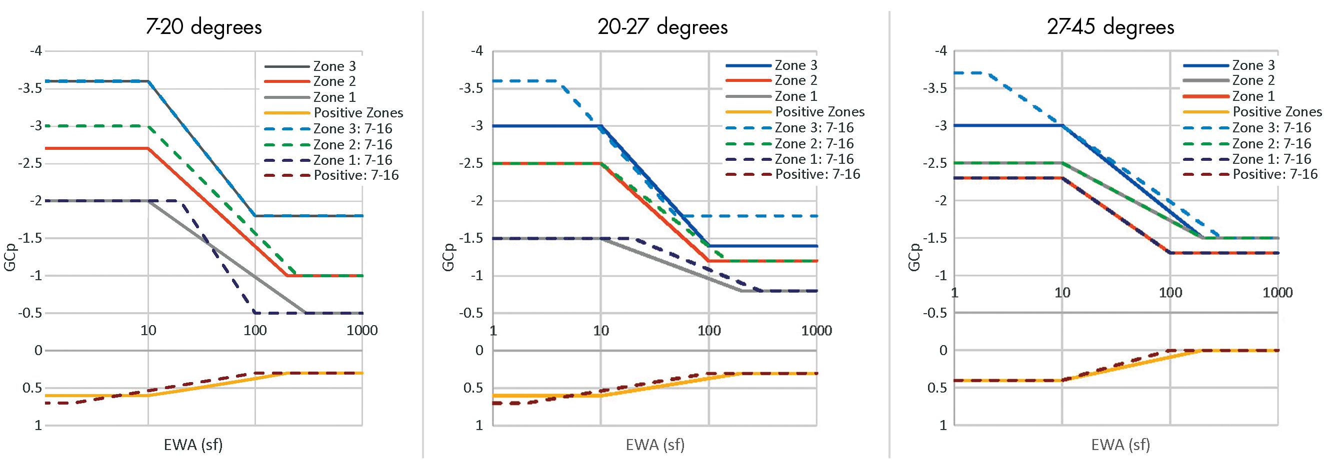
3) Minimized the number of greatest EWAs to either 100, 200, or 300 square feet
4) Eliminated the need to determine h/B ratios for hip roofs (i.e., h/B is the ratio of roof height to least horizontal dimension)
5) Eliminated the equations for hip roofs of 27° to 45° to a simple set of graphs for only 45° and an interpolation formula that can be used to determine (GCp) coefficients for roof slopes that vary from 27° to 45°
6) Eliminated the graphs for roof overhangs on gable roofs with slopes greater than 7° and all hip roofs with a formula that adds
the (GCp) for the upper roof surface to the (GCp) for the wall surface adjusted for the applicable EWA 7) Modified the (GCp) equations in the Chapter 30 commentary to match the chapter changes e changes in EWAs and the reduction in roof zones are best represented by comparing the ASCE 7-16 and ASCE 7-22 roof GCp graphs. Figure 1 illustrates the comparisons in gable roof EWAs and (GCp) values. ASCE 7-22 is shown in solid lines; ASCE 7-16 is shown in dashed lines. While there are some changes in EWAs, the basic tenet in developing C&C wind load updates was to preserve the wind tunnel testing basis used for the ASCE 7-16 standard. Raw wind tunnel results were used to construct graphs to meet practitioner

use objectives while preserving the integrity of the extensive wind tunnel results.










Figure 2 illustrates the comparisons in hip roof EWAs and (GCp) values. For ASCE 7-22, it was found unnecessary to vary the (GCp) with h/B values, simplifying the presentation of values. e graph for the 45° hip roof compares the ASCE 7-16 values for 45° using the required equations with the proposed (GCp) values for 45° for ASCE 7-22.
e following example illustrates the differences in C&C pressures between ASCE 7-16 and ASCE 7-22. e example location is Kansas City, MO, with a 110-mph design wind speed; the mean roof height is 20 feet; the exposure is Exposure B; the internal pressure is characterized


Figure 3. Roof overhang for Zone 2e, extracted from ASCE 7-16 Figure 30.3-2G.
as a partially open building; the site elevation is 897 feet. The resulting C&C pressures are shown in the Table (page 16 ) for a velocity pressure of 15.8 psf. For those coefficients that could not be read from the graphs, the equations in the ASCE 7-22 commentary were used.
The ASCE 7-16 (GCp) coefficient for a hip roof Zone 3 location (no overhang) with a 35° slope and an EWA of 20 square feet is determined from the equation (GCp) = 1.25-0.108*θ = -2.53. In ASCE 7-22, the (GCp) value for a 35° slope is interpolated between the (GCp) value for 27° and 45°. The (GCp) value for 27° and EWA of 20 square feet is -3.00+1.00logA = -1.7 and the value for 45° and EWA of 20 square feet is -3.80+1.40logA = -1.98. These two values must then be interpolated using the formula shown in Figure 30.3-2G. The interpolation formula for this example is: (1.98-1.7)*(35°-27°)/ (45°-27°)+1.7 = 1.82.
Determining (GCp) coefficients for roof overhangs in ASCE 7-16 required reading a different graph (or using a different set of equations) than was required for the main roof. For example, the overhang (GCp) coefficients for a hip roof with a slope of 20° – 27° are shown in Figure 3 (Figure 30.3-2G from ASCE 7-16 ). Zone 2e (zone along the eave) with EWA of 10 square feet or less has a coefficient of -2.5.
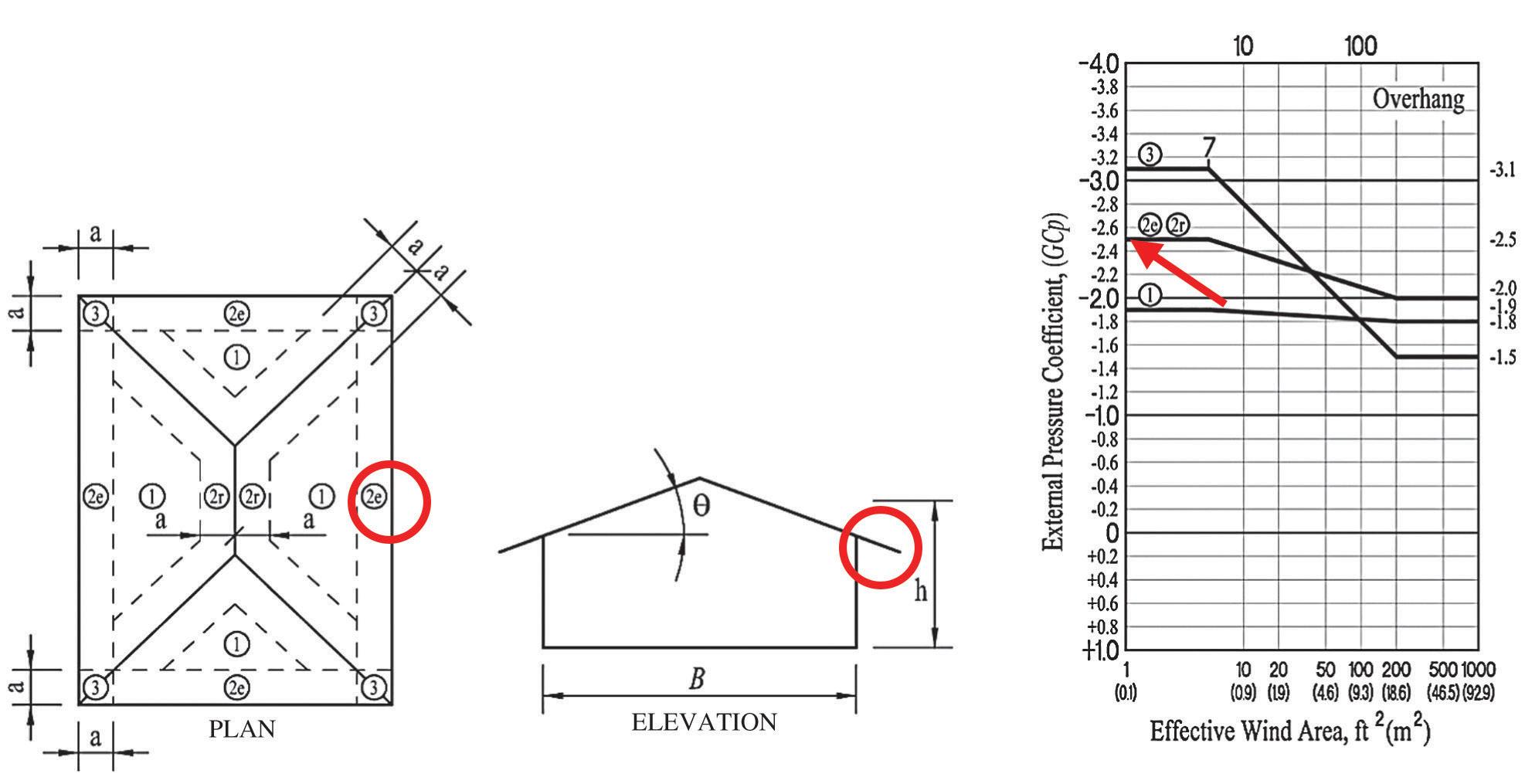
This coefficient includes pressure contributions from the overhang’s upper and lower surfaces.
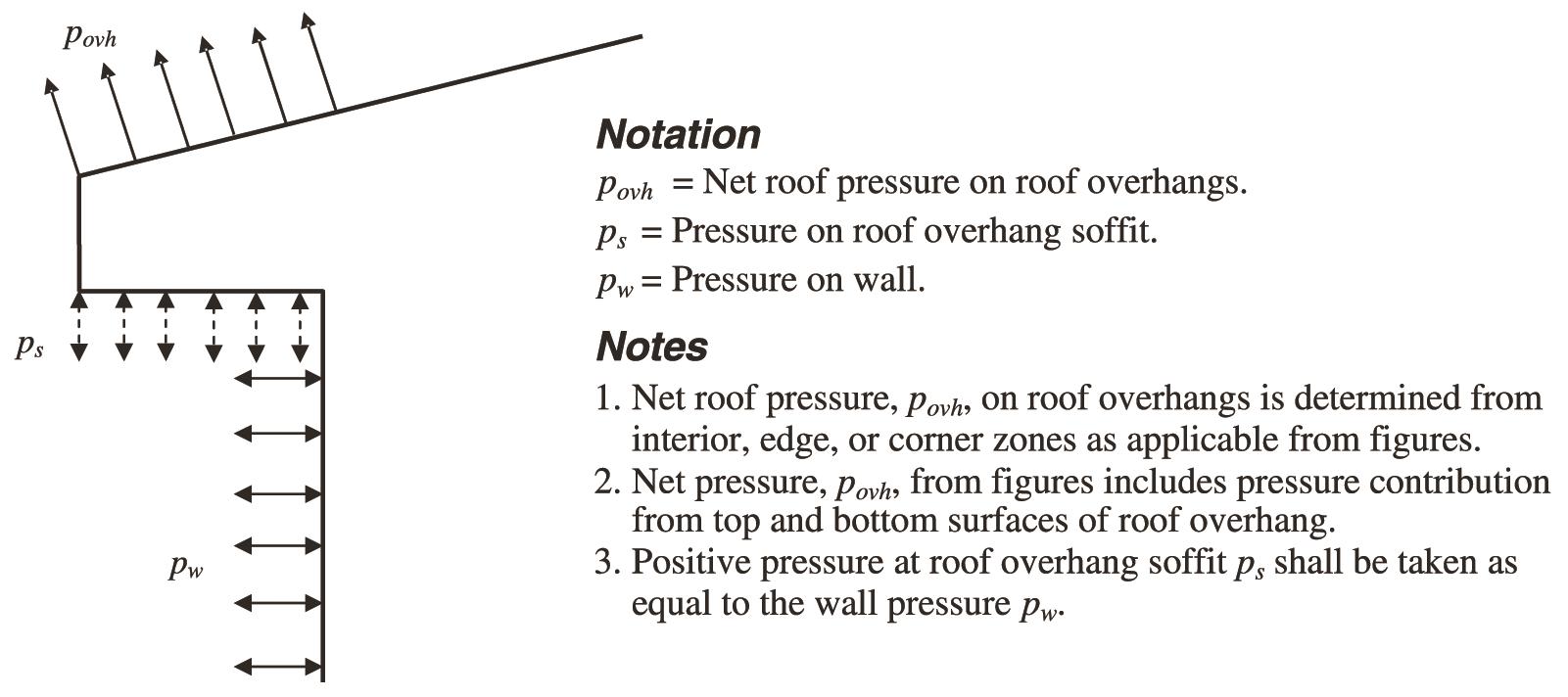
ASCE 7-22 has simplified this process by simply adding the roof surface coefficient to the wall surface coefficient at a point of interest on the overhang. The process is shown in Figure 4 (Figure 30.7-1 in ASCE 7-22).
Using the ASCE 7-22 process yields a (GCp) coefficient for the same Zone 2 as shown above of -2.0 (Figure 30.3-2F from ASCE 7-22) for the roof surface contribution and +1.0 (Figure 30.3-1 from ASCE 7-22) for the wall surface contribution for a total of -3.0 coefficient. The theory is that positive wall pressure washes up the wall and strikes the underside of the soffit, adding to the uplift pressure on the top of the roof surface.
The C&C (GCp) coefficients developed for ASCE 7-22 are typically either the same as ASCE 7-16 or slightly lower (Table). Thus, the required design pressures for C&C are slightly reduced. Since the basic results found in the wind tunnel studies that support the coefficients did not change from ASCE 7-16 to ASCE 7-22, the coefficient results are not expected to change dramatically. The reductions, where they occur, primarily result from the simpli fication methods and increased EWA basis described in this article. The authors hope that the practice finds these simplifica tions for determining C&C wind pressures helpful.■
William Coulbourne is a Structural Engineering consultant with Coulbourne Consulting, Churchton, MD.

Philip Line is Vice President of Codes & Regulations for the American Wood Council, Leesburg, VA.
Figure 4. C&C wind Loading on overhangs, Figure 30.7-1 in ASCE 7-22.
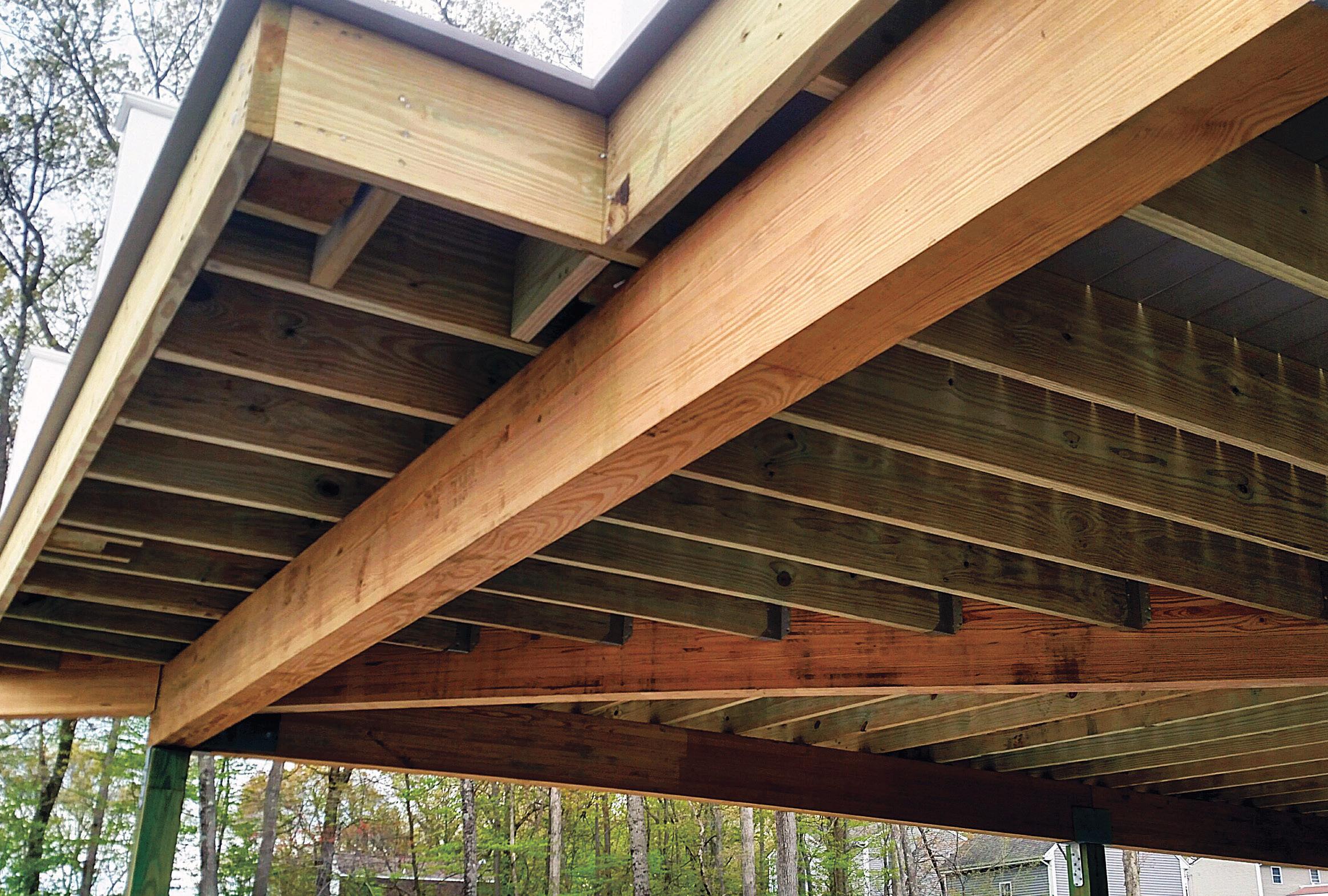
• Manufactured with superior strength southern yellow pine MSR Lumber.
• Offered in two oil-borne preservative treatments: Clear-Guard™ and Cop-Guard®.
• Fast, easy, one-piece installation that’s more efficient than bolting or nailing multi-ply dimension or structural composite lumber members together.
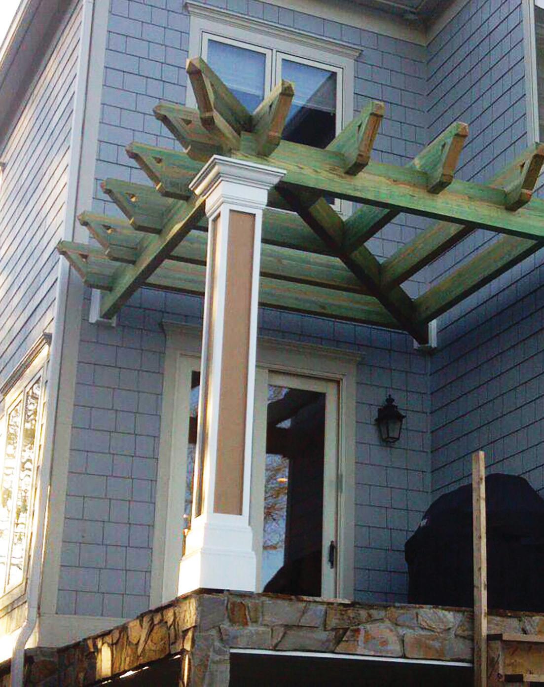
• Excellent choice for decks, boardwalks, pergolas, covered porches and demanding environments such as bridges, highway sound barriers, railroad cross ties, and floating docks.
• 25-year warranty from the treater.
Anthony Forest Products


The design of structures utilized to support fall protection systems (FPS) for workers at height is a topic that is often researched and questioned but is not a straightforward process. Unlike other common structures with design requirements such as loads, factors of safety, and minimum requirements defined in their respective codes and design guides, the design requirements for fall protection loads can be somewhat ambigu ous. This article aims to provide a basic overview of FPS, define what regulations and standards exist in this space, and recommend a best practice approach for engineers to define strength require ments for fall protection anchorages.
Why is fall protection so important? A United States Bureau of Labor Statistics news release dated December 16, 2021, states that in the U.S. alone, a worker died every 111 minutes in 2020 from a work-related injury. Of the 4,764 occupational fatalities in that year, 645 resulted from a worker falling from a height to a lower level. Falls to a lower level were the second leading occupational fatality across all industries following transporta tion incidents. Additionally, falls were the leading cause of workplace fatalities in the construction industry.
What components comprise a personal FPS? United States Occupational Health and Safety Administration (OSHA) defines a personal FPS in OSHA 1910.140 as: “Personal fall protection system means a system (including all components) an employer uses to provide protection from falling or to safely arrest an employee’s fall if one occurs.”
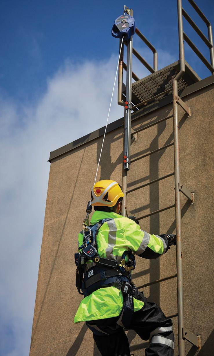
Elementary ABCs are utilized in the fall protection industry to lay out the basic components of fall protection. Figure 1 shows the primary components of an FPS. Also, note the additional components one should always consider. In the graphic: A stands for anchorage. Anchorages are a secure attachment point for an FPS, varying by industry, job, type of installation, and structure.
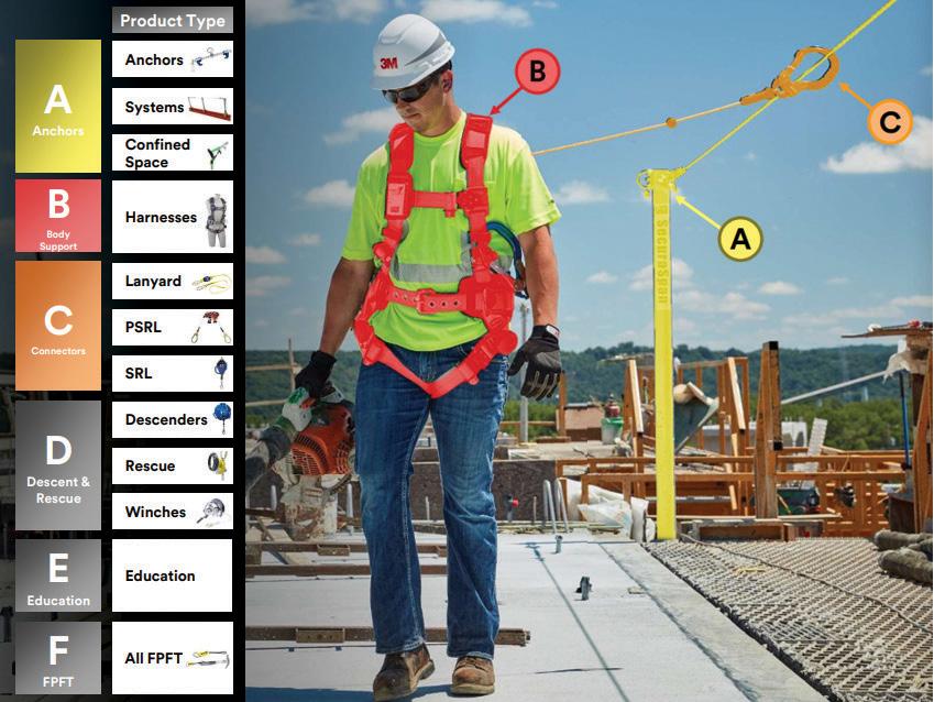
B stands for body support. Body support in a personal FPS is typically a full body harness that distributes fall forces over the upper thighs, pelvis, chest, and shoulders.
C stands for connector. Connectors in a personal FPS are typically
self-retracting lifelines (SRL), shock-absorbing lanyards, or restraint lanyards.
D stands for descent and rescue. Descent and rescue devices raise or lower a fallen and/or injured worker to safety or rescue/ retrieve them from a confined space.
E stands for education. Education is essential in specifying and using a personal FPS. The specifier, as well as the user, must be properly trained in fall protection.
F stands for fall protection for tools
Fall protection for tools and dropped object prevention help make work environments safer and more pro ductive by helping reduce dropped object incidents.

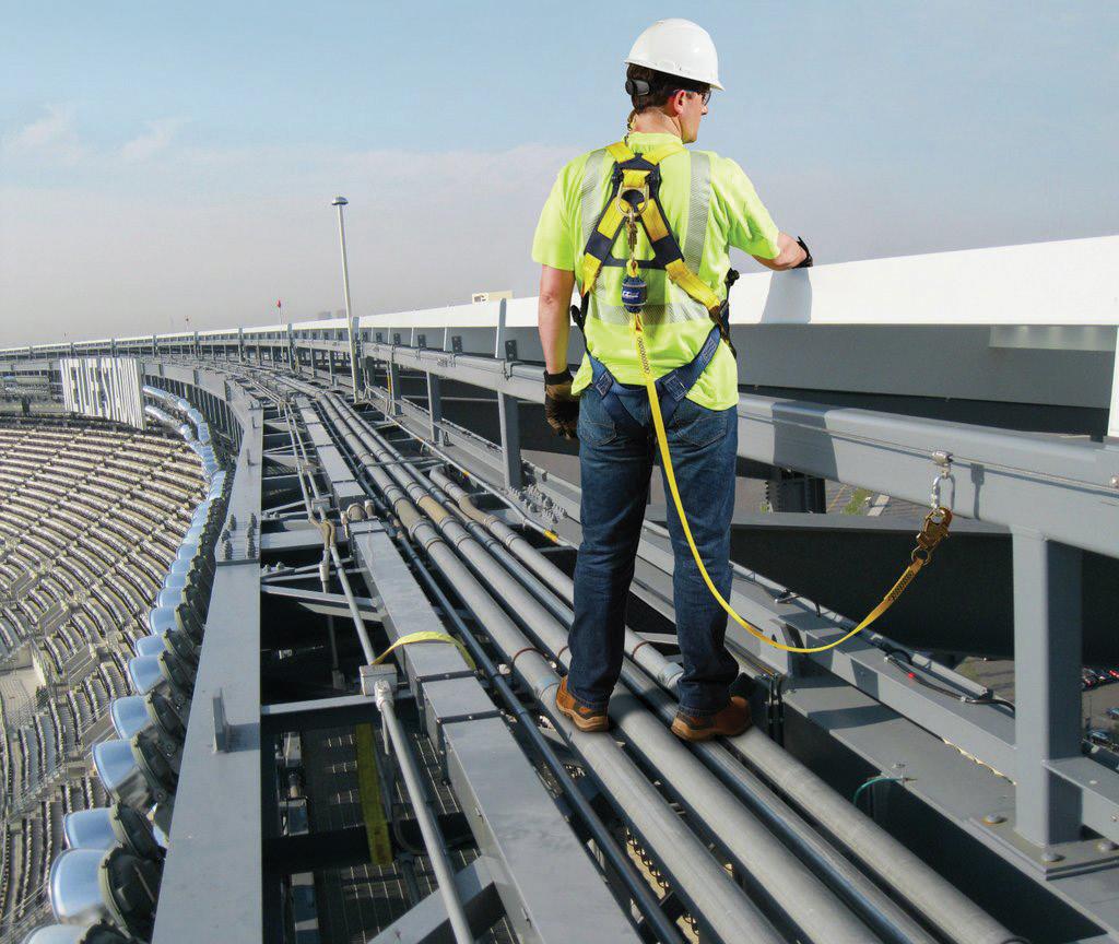
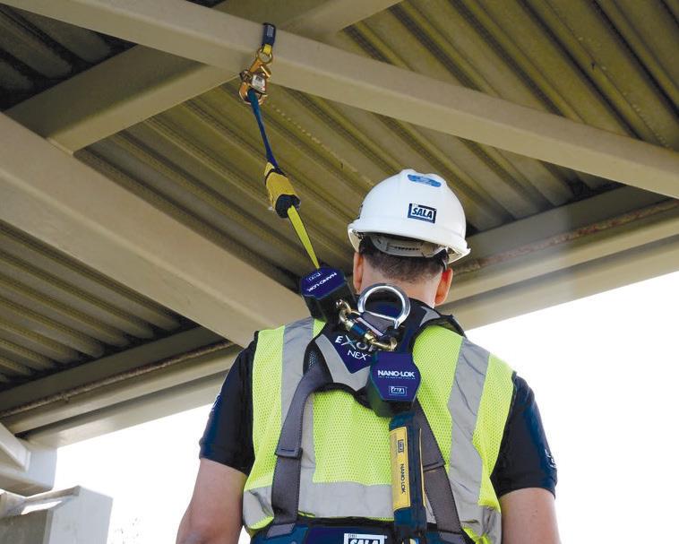
All of these components work together to form a complete personal FPS. Figures 2 through 6 (page 22) provide examples of FPS combinations and applications.
The science of a fall and the forces trans ferred to the anchorage point create a unique design load scenario. When a worker falls, a force is generated that can vary depending on their weight, position, fall distance, PPE, and various other fac tors. This is referred to as their fall arrest force in the fall protection industry.
The human body is likely to sustain a range of mild to life-threatening injuries if subjected to this entire fall arrest force,
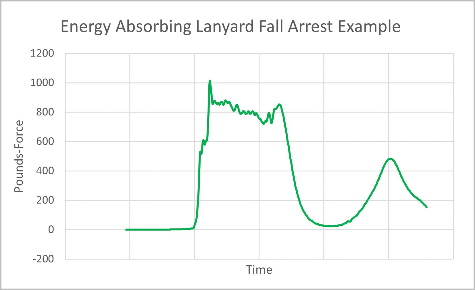
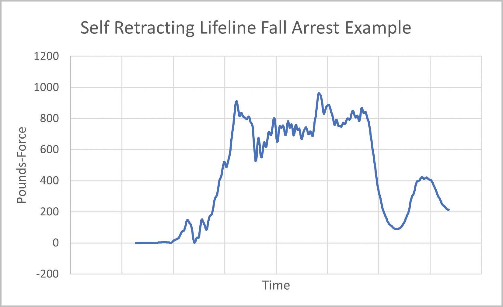
particularly if the harness is not worn cor rectly. This is why fall protection products are required and designed to absorb and limit the fall arrest force. Fall protection products are designed to reduce these forces using energy absorbers such as a tearaway web or a rotating friction brake. These energy absorbers limit the fall arrest forces trans ferred through the FPS and safely arrest the worker’s fall. Figure 7 (page 23) shows an example of a tear web energy absorber, and Figure 8 (page 23) shows an example of a rotating friction brake. Both are examples of the force vs. time distribution in a fall event using an energy-absorbing lanyard or selfretracting lifeline as a connector in an FPS.

Some specific standards and regulations apply to an FPS based on where the per sonal protective equipment (PPE) is used worldwide. Regulations vary by country and, in some cases, by state. Most FPS are regu lated by the respective country’s government occupational health and safety authority. In the United States, this is OSHA. In addition to the requirements set forth by the regula tory body, standard-setting organizations have detailed design and testing criteria that manufacturers can use to receive a certification mark. In the U.S., for example, the American National Standards Institute (ANSI) maintains a set of standards for the design and testing of FPS, ANSI/ASSP Z359 Fall Protection Standards. The remainder of this article focuses on U.S. practice.
At a minimum, an employer must use an OSHA-compliant FPS. In addition, some state-level OSHA regulations maintain that all FPS must be ANSI/ASSP Z359 compliant. Therefore, as a best practice, employers and engineers are recommended to purchase, specify, and design FPS that are OSHA and ANSI/ASSP Z359 compliant unless under a specific circumstance.
Regarding FPS anchorages, it is impor tant to understand the OSHA definitions of competent and qualified persons. OSHA 1910.140: “Competent person means a person who is capable of identifying existing and predictable hazards in any personal fall protection system or any component of it, as well as in their application and uses with related equipment, and who has authoriza tion to take prompt, corrective action to eliminate the identified hazards,” whereas “
Qualified describes a person who, by pos session of a recognized degree, certificate, or professional standing, or who by extensive knowledge, training, and experience has successfully demonstrated the ability to solve or resolve problems relating to the subject matter, the work, or the project” (emphasis added ).
Typically, a safety professional who is edu cated on FPS and able to specify equipment is a competent person. A qualified person is usually an engineer who is educated on FPS, able to calculate structural loads, and able to qualify that the anchorage point can adequately support the FPS. In many cases, the employer/owner responsible for the FPS may require this engineer to be a professional engineer.
Anchorage design strength requirements are determined based on whether a competent or qualified person evaluates the anchorage strength. OSHA breaks these two anchorage designations into noncertified and certified anchorages. A non-certified anchorage, according to OSHA 1910.140(c)(13)(i), is defined as “capable of supporting at least 5,000 pounds (22.2 kN) for each employee attached.” A certified anchorage, according to OSHA 1910.140(c)(13)(ii), is defined as “designed, installed, and used, under the supervision of a qualified person, as part of a complete personal fall protection system that maintains a safety factor of at least two.” ANSI/ASSP Z359.0 defines these two anchorage strength requirements in section
2.110: Non-Certified Fall Arrest Anchorage, “A fall arrest anchorage that a competent person can judge to be capable of supporting the predetermined anchorage forces as prescribed in these standards.”
Section 2.23 defines certified anchorage as “an anchorage for fall arrest, positioning, restraint or rescue systems that a qualified person certifies to be capable of supporting the potential fall forces that could be encountered during a fall or that meet the criteria for a certified anchorage prescribed in these standards.” (Emphasis added.)
What does this mean for anchorage design? A non-certified anchorage must be capable of supporting 5,000 pounds and requires a competent person to sign off on it. At the competent-person level, general guid ance is, can you hang a half-ton pickup truck off the anchor point? A certified anchorage requires a qualified person to design and/or sign off on the anchorage. A factor of safety (FOS) of 2:1 means the anchor can hold twice the foreseeable load.
An FPS can be used for fall arrest, work positioning, fall restraint, rescue, and horizontal lifelines, each requiring different anchorage strength. The Table provides an overview of different anchorage strength requirements. 3M also provides a technical bulletin detailing these requirements – https://bit.ly/3QymlBU
How should engineers approach the design of an anchorage point as a qualified person? A typical approach is to start with the highest anchorage strength achievable and then sharpen the pencil as needed to deem an anchor point as adequate. As anchorage design strength is reduced, additional controls are needed to ensure the design strength
is never met or exceeded. This anchorage design approach is called the hierarchy of anchorage design strength for qualified persons
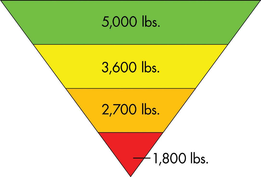
As shown in Figure 9, the starting point is 5,000 pounds (22.2 kN). This anchorage strength can be selected by a competent person or designed by a qualified person. This can either be a non-certified anchorage or a certified anchorage. A qualified person should always begin with this load to evaluate if the anchorage can meet that con servative requirement.
The next step is 3,600 pounds (16 kN) which makes this anchorage no longer a non-certified anchorage. It is now a certified anchorage that a qualified person selects. This load includes an FOS of 2:1, which means it is designed to hold 1,800 pounds (8 kN). OSHA 1910.140(d)(1)(i) states that the employer must “limit the maximum arresting force on the employee to 1,800 pounds.” Due to this federal regulation, all FPS components in the U.S. must limit the arrest forces in an FPS to 1,800 pounds. Manufacturers of fall protection products utilize energy absorption methods to reduce fall arrest forces and meet OSHA requirements. This means that regardless of which manufacturer’s fall protection products one uses, the anchorage point is not subjected to a load greater than 1,800 pounds so long as the FPS is OSHA compliant and is used following the manufacturer’s user instructions. Therefore, this 3,600-pound load is considered the industry standard design load for a certified anchorage.
The next step is 2,700 pounds (12 kN). This load can only be used for a certified anchorage designed by a qualified person. This 2,700pounds anchorage load includes an FOS of 2:1, meaning it is designed to hold 1,350 pounds (6 kN). Manufacturers may design and sell products with a maximum arrest force of less than 1,800 pounds (8 kN) to provide additional user value and comply with specific standards such as ANSI/ASSP Z359. The ANSI/ASSP Z359 set of standards establishes the maximum arrest force in some product classes for a personal FPS to be 1,350 pounds. Therefore, if an engineer needs to design the anchorage strength down to 2,700 pounds, they can do this by specifying that only FPS components with a maximum arrest force of 1,350 pounds may be utilized with this anchorage point. When designing to this anchorage strength load, it is highly recommended to put controls in place to either make the specific FPS components unable to be switched with components not complying with the 1,350 pounds maximum arrest force requirement or “lockout/tag-out” (LOTO) the system to require a check to be performed to confirm all components are compliant before utilizing the FPS.
The last level is 1,800 pounds. This load can only be used for a certified anchorage designed by a qualified person. The FOS of 2:1 means this 1,800-pound anchorage load is designed to hold 900 pounds (4 kN). As discussed previously, manufacturers can choose to design and sell products with less than the OSHA’s 1,800 pounds maximum arrest force; some manufacturers do sell FPS components with a 900 pounds maximum arrest force for applications such as
this. Engineers needing to design the anchorage down for this load must specify that only FPS components with a maximum arrest force of 900 pounds may be utilized with the anchorage point. It is highly recommended to put controls in place to either make the complete FPS components unable to be switched with components not complying with the 900 pounds maximum arrest force requirement or use the LOTO approach, as previously mentioned. A qualified person should only choose to design this load with great caution and appro priate controls in place. This design load level should only be considered if all other options are unattainable, and the fall protection hazard cannot be avoided altogether.
When an engineer designs an FPS fall arrest anchorage, what considerations should be taken? Fall protection anchorage loads fall into a unique category where requirements are specified by OSHA and do not fall under any specific sec tions of typical engineers’ building or material design codes. However, there are two key points to consider when designing fall arrest anchorages.
First, the anchorage structure is allowed to deform in a fall arrest event. It is the responsibility of the engineer to determine acceptable deformation limits. If deformation is allowed in the anchorage design, testing a sacrificial anchorage point is recommended to confirm that the structure performs as designed. If an anchorage point is subjected to a fall event, the anchorage point and FPS components must all be taken out of service and discarded or repaired.
Figure 7. A force vs. time graph of an energy-absorbing lanyard arresting a test weight.
Second, consider safety factors. As noted previously, OSHA requires a 2:1 FOS for all FPS, including the anchorage structure. When pre-engineered fall protection products are intended to be attached to an anchorage structure, the manu facturer typically specifies an anchorage strength requirement. These anchorage strength requirement values typically already include a 2:1 FOS. Always confirm with the manufacturer if you are unsure if the FOS load is included. Due to fall-protection anchorage loads falling into the OSHA category rather than a traditional struc ture’s design code or material code, this OSHA 2:1 FOS is usually the only required safety or load factor for the design of an FPS anchorage. It is at the discretion of the engineer, employer, structure owner, and local authorities if an additional load factor is required. An engineer
Figure 8. A force vs. time graph of a self-retracting lifeline arresting a test weight.
needs to have a respectable education in FPS before being deemed a qualified person to design FPS anchorage structures.
The design of an FPS anchorage can be quite simple from a requirement and design complexity standpoint but should also be undertaken with great discernment for the purposes it is used for in the event of a fall. Always check for specific local or structure-owner design requirements and the specific manufacturer’s instructions for the FPS components being utilized. The hierarchy of anchorage design strength approach is a best practice to begin conservatively and reduce if needed while taking great consideration when doing so. From a worker’s safety approach, when specifying/designing an FPS/anchorage, always stop and first reconsider if there is a way to design out the need for that employee to be working at heights in the first place.
■
Reference included in the PDF version of the online article at STRUCTUREmag.org

Heidi Lopez-Hidalgo is a Senior Application Engineer for 3M Fall Protection. She is a fall protection subject matter expert and a licensed professional engineer with a background in structural engineering (hlopezhidalgo@mmm.com).
Figure 9. The hierarchy of anchorage design.
 By Hee Yang Ng, MIStructE, C.Eng., P.E.
Bored piles primarily carry static vertical loads when supporting a building. In designing such piles, the shaft resistance and end bearing are often estimated when determining the pile’s load-carrying capacity. To ensure satisfactory performance, the pile also needs to meet specific settlement criteria at working loads. One helpful aid in pile design is using numerical simulations. With advances in computing, access to numerical simulations has become widely available and often quite economi cal. This article highlights some practical aspects of numerical simulations which can be helpful in pile design.
Figure
Examples of three-dimensional, axisymmetric, and plane strain models.
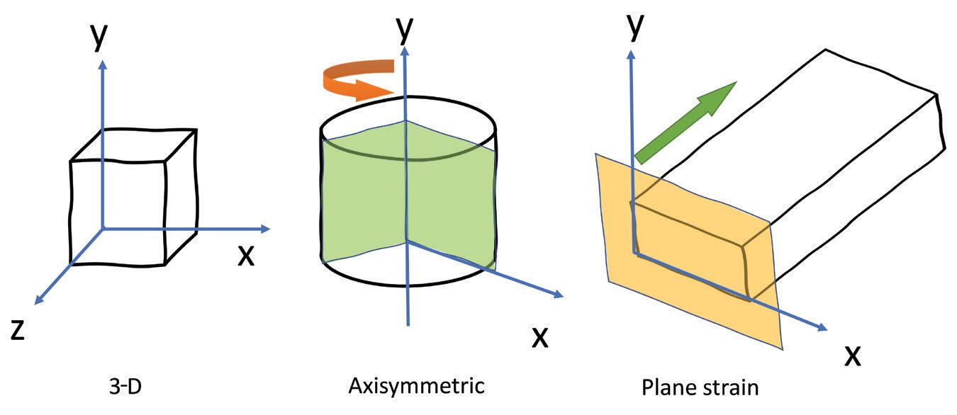
Numerical models can be three-dimensional (3-D) or two-dimensional (2-D). Many real-life three-dimen sional geotechnical problems with uniform cross-sections can be simulated using 2-D axisymmetric or plane strain models that are much simpler to model and run than full 3-D models (Figure 1). However, users must be mindful of the units when working with inputs and outputs. For example, in an axisymmetric model, if the
loading is in units of force/area, it is necessary to multiply by πr2 (r being radius) to obtain the load. Similarly, if an axial load output from the model is in force/radian, it is necessary to multiply by 2π to obtain the actual axial load. On the other hand, plane strain models are typically modeled in unit length (e.g., per foot or meter run) in the out-of-plane direction.
In design, the ultimate capacity for shaft resistance and end bearing of piles can be correlated to the standard penetration test (SPT) N value and soil undrained shear strength su. For bored piles, an example of commonly used correlations is given in Table 1.
Consider a case study of a 6.6-foot (2m) diameter bored pile of length 49.2 feet (15m) embedded in sand with no groundwater encountered. The average shaft resistance, fs, can be given by K s( tan
, where K s,
, and
are the coef ficient of earth pressure, friction angle between the pile and the sand, and effective overburden pressure, respectively. Average fs is approximately 1*tan(0.75×35)*(7.5*20) which is 1.5 ksf (74kN/m 2). For end bearing, using SPT N=30 (dense sand), q b is 100*30, which is 62.7 ksf (3,000 kN/ m 2). An axisymmetric model is chosen to model this in a numerical simulation where only one-half of the geometry is modeled. The actual model can be obtained when rotated 2π about the axis of symmetry. A finite element software
Correlation
pile
to SPT N and shear strength.
was used for the numerical simulation in this article.
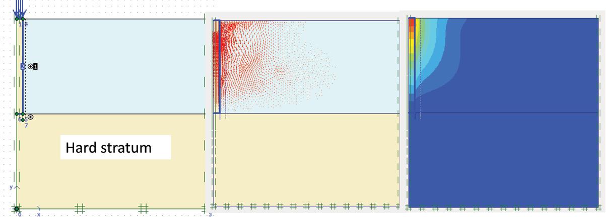
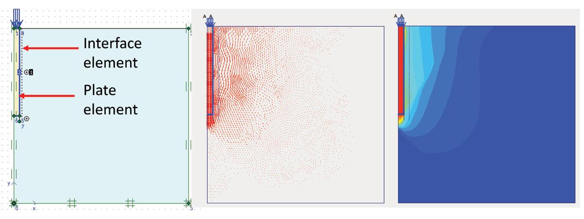
Figure 2 shows the pile loaded to failure with the displacement vector plots and color shading. It is worth noting that the pile head and pile toe are stiffened with plate elements to ensure good load transfer at pile top and base (i.e., assuming good pile toe condition). An interface element is added at the pile-soil interface and a plate element is added along the pile shaft to capture the shaft resistance and variation of axial load along the shaft. However, this dummy plate element along the pile shaft only captures the variation of axial load, working as a sensor to sense the load. Therefore, the axial stiffness EA (Young’s modulus multiplied by cross-sectional area) of the plate should be made as small as possible to avoid attracting unnecessary load (e.g., scale down 106 times smaller than actual EA). This plate has practically no effect on the loading process. Actual axial force in the pile can then be obtained by scaling up accordingly from the minimal load obtained in the dummy plate element.
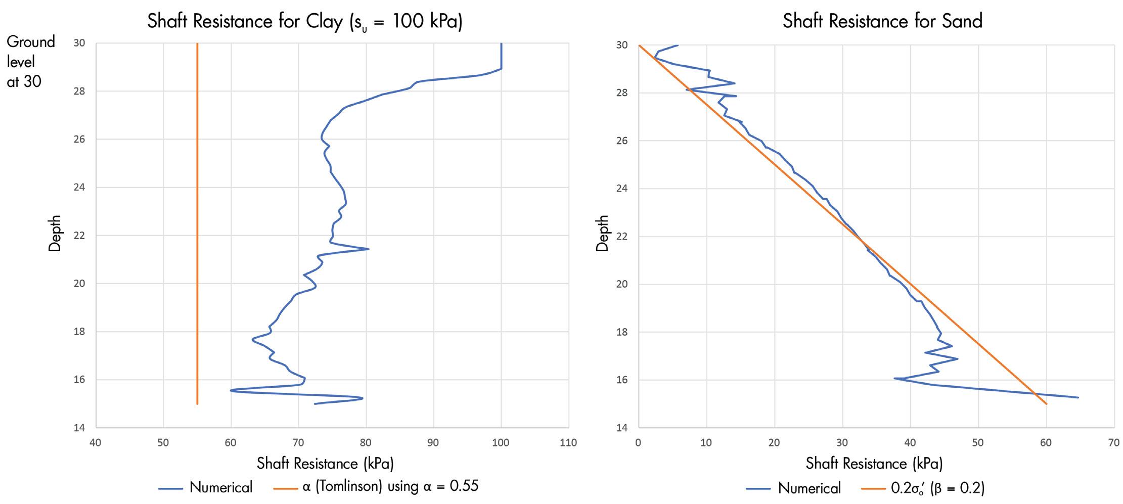
The interface element is deliberately extended slightly beyond the pile toe and into the soil body. This is to better condition or smooth the sudden change in boundary condition at the pile toe where high-stress peaks might occur, resulting in stress oscillations (jagged stress plots) that are not realistic. The interface element also allows a strength reduction factor to be applied to the friction angle and cohesion of the interface, if necessary. This might be used, for example, in the case of debonded piles (by bitumen coating on pile shaft) to reduce down drag. Compare the much smaller displacement plots for the pile shaft soil with debonding applied at the shaft (where a 0.67 strength reduction factor is used) in Figure 2
Figure 3. Plot of shaft resistance and axial load along the pile shaft.
From the displacement plots in Figure 2, it can be seen that the pile has uniform displacement (uniform red color shading), which is in line with the expectation of it moving as a rigid body. This is pro vided the pile is a floating (or friction) pile where the capacity comes mainly from shaft resistance (e.g., no hard stratum encountered at the pile toe). Contrast this to a displacement plot of an end-bearing pile (e.g., rock-socketed) with virtually zero movement at the pile toe. As a result, the pile shortens the most at the pile head and gradually decreases down the shaft.
next page
When loaded to failure in uniform soil, pile toe soil displacement is generally larger than pile shaft soil displacement, reflecting the relatively smaller movement along the pile shaft required to develop shaft resistance compared to end bearing (i.e., direct shear at shaft compared to punching shear at base). A typical punching shear failure for soil can be observed at the pile toe, which has a characteristic conical wedge failure pattern.
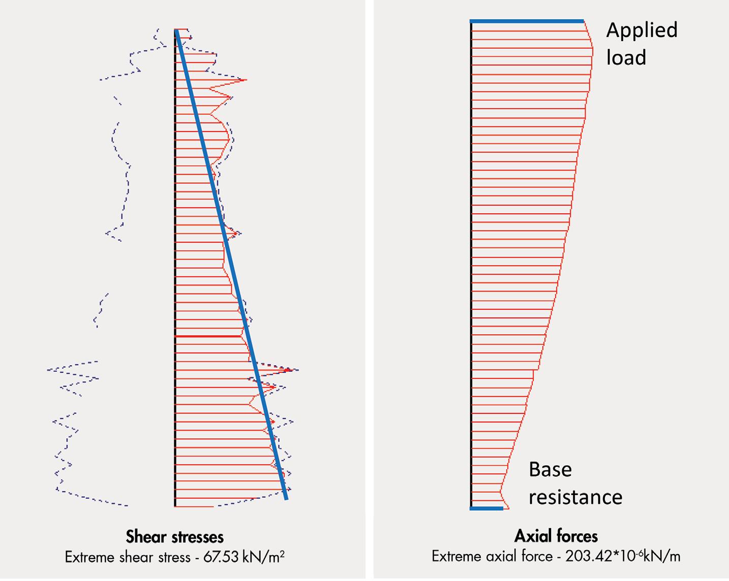
Figure 3 (page 25) shows shaft resistance and axial load along the pile shaft. As overburden pressure increases with depth, shaft resis tance is expected to increase accordingly. When a pile is loaded from the pile top, shaft resistance is expected to develop first before the load gets resisted by end-bearing. Therefore, the axial load along the shaft should show an inverted triangular or trapezoidal shape which decreases from pile top (i.e., the applied axial load) to pile base (load taken by base) as the soil along the shaft gradually takes up more load. From this plot, both shaft resistance and end bearing from the numerical model can be obtained and compared with design values assumed from empirical correlations.
Figure 4 (page 25) shows an example of shaft resistance variation along the shaft of the same 6.6-foot (2m) diameter pile in clay and sand when compared with the αsu and βσo ’ formulas, where α and β are coefficients to modify undrained shear strength and effective overburden pressure, respectively. It can be seen that numerical simulations can give moderately good results. However, one must remember that the result provided by numerical simulations is only
as good as the input. The results may vary significantly when certain parameters are changed. One example is the selection of the thickness of interface elements when dealing with soil-structure interaction problems. The designer may need to calibrate a particular problem to find out the appropriate values for the case to provide stable, reasonable, and consistent answers. Care should be taken not to extrapolate calibrated values to other situations that do not have the same conditions.
Consider a case of a 24-inch (600mm) diameter bored pile of length 66 feet (20m) embedded in the following soil condition (Table 2 ): granitic residual soil overlying highly weathered rock. The working load for the pile is 450 kips (2 MN).
0-23 (0-7) 10 Residual soil
23-46 (7-14) 40 Residual soil
>46 (14) 100 Highly weathered rock
Figure 5 shows a plot of a static pile load test carried out using a kentledge (counterweight made up of con crete blocks), loaded up to 3.5 times the working load, and then unloaded. Three numerical simulations were carried out using a discrete staged loading process (i.e., with gradual load increment at every stage), with varying stiffness adjusted only for the SPT100 soil layer. Young’s modulus varied from 10,400 ksf (500 MPa) to 31,300 ksf (1,500 MPa). All other parameters remain unchanged. Materials were mod eled using a classic Mohr-Coulomb constitutive model. It can be seen that predicted pile settlement using numerical simulation is highly dependent on the parameters selected, especially the stiffness value. Note that all three simulations gave similar results for settlement at lower loads (e.g., working load). One reason could be the unchanged soil parameters for the upper layers, which carried most of the load at lower load levels. As expected, the curve using the lowest stiffness of 10,400 ksf (500 MPa) showed the highest stiffness degradation when loading increases and the highest residual settlement. This example underscores the importance of piles to be founded on a competent stratum for a satisfactory load-settlement response.
Given the good settlement performance of the pile, the same 24-inch (600mm) diameter pile is now shortened to 46 feet (14m) and numerically simulated to produce a load-settlement curve ( Figure 6 ). The load is specifically chosen to load it beyond pro ducing a settlement of 2.4 inches (60mm). Some codes (e.g., CP4
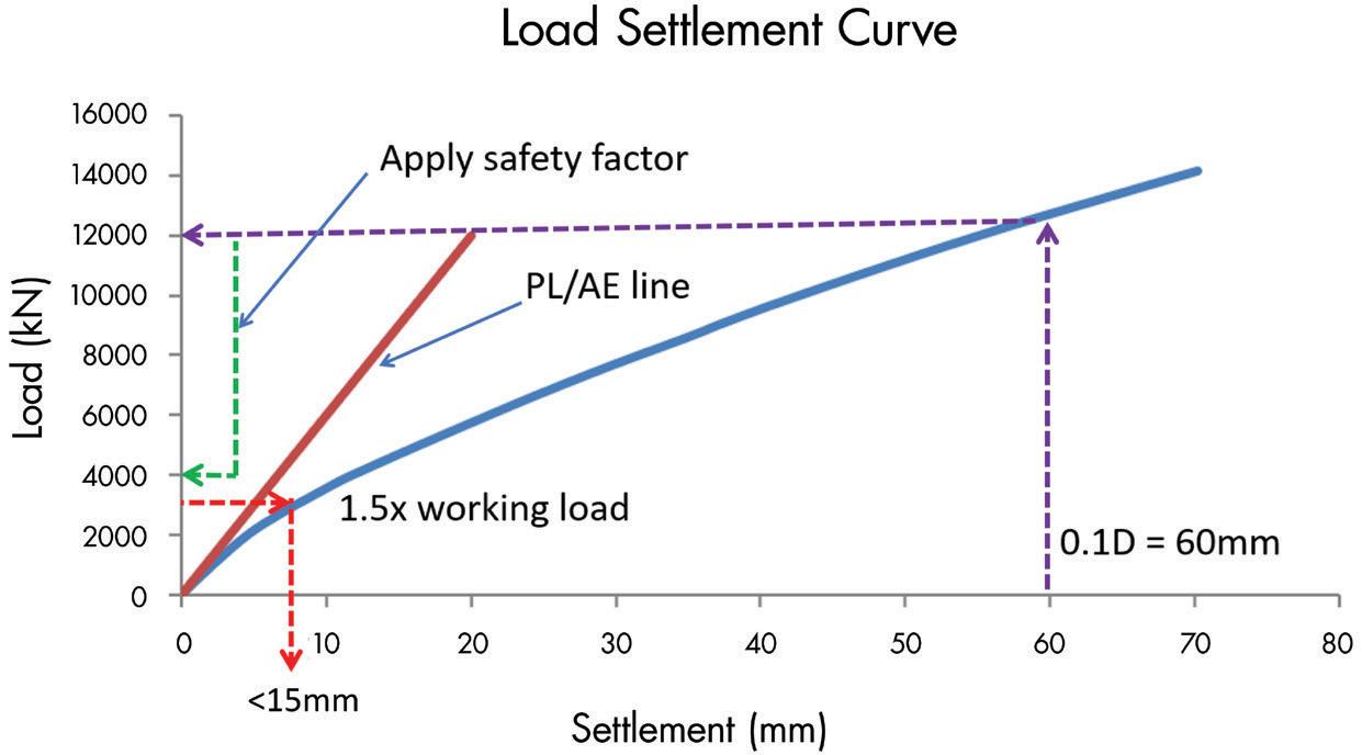
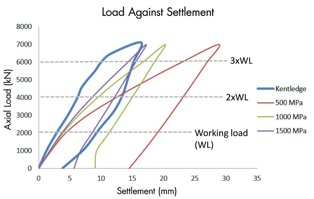
– Code of Practice for Foundations , Singapore) have recommended that the ultimate bearing capacity of piles be taken as 0.1D, where D is the pile diameter. In the U.S., a common way to define fail ure load is the load producing a settlement of (PL/AE + 0.15 + D/120) in inches, where D is the pile diameter. This is known as the Davisson method and can also be found in NAVFAC DM7-02
– Foundations and Earth Structures . Hypothetically, the working
Top publications from ICC help you learn, interpret and apply the code



2021 IBC Code & Commentary Volumes 1 & 2 Search #3010S21 at shop.iccsafe.org
This helpful set contains the full text of 2021 IBC, including tables and figures, followed by corresponding commentary at the end of each section to help code users understand the intent of the code provisions and learn how to apply them effectively. Volumes also sold separately.
Reinforced Masonry Engineering Handbook, 9th Edition Search #9346S9 at shop.iccsafe.org
Based on 2021 IBC and TMS 402/602-16, MIA’s newly updated Handbook eliminates repetitious and routine calculations to help designers save time. In addition to the code requirements, it provides sound engineering practice, detailed explanations, 90+ examples, and hundreds of drawings.
Concise, visual explanations provide an overview of the code without complex explanations. Each book contains design aids, figures, flowcharts and examples to provide step-by-step procedures that engineers can follow to determine loads and correctly apply the code.
Flood and Tsunami Loads: Time-Saving Methods Using the 2018 IBC and ASCE/SEI 7-16 Search #9021S18 at shop.iccsafe.org

Seismic Loads: Time-Saving Methods Using the 2018 IBC and ASCE/SEI 7-16 Search #9022S18 at shop.iccsafe.org

Wind Loads: Time Saving Methods Using the 2018 IBC and ASCE/SEI 7-16 Search #9023S18 at shop.iccsafe.org
Rain, Snow, and Ice Loads: Time-Saving Methods Using the 2018 IBC and ASCE/SEI 7-16 Search #9020S18 at shop.iccsafe.org


Easy access, seamless onboarding, administrative reporting
Tailored for teams of 20 or more, a customized Enterprise package enables organizations to search, share, collaborate and manage building codes all in one place. This can help to save valuable time, reduce costly errors and improve a firm’s


To schedule a demo or for more information, contact Phil Anthony panthony@iccsafe.org. your free 14-day trial, visit


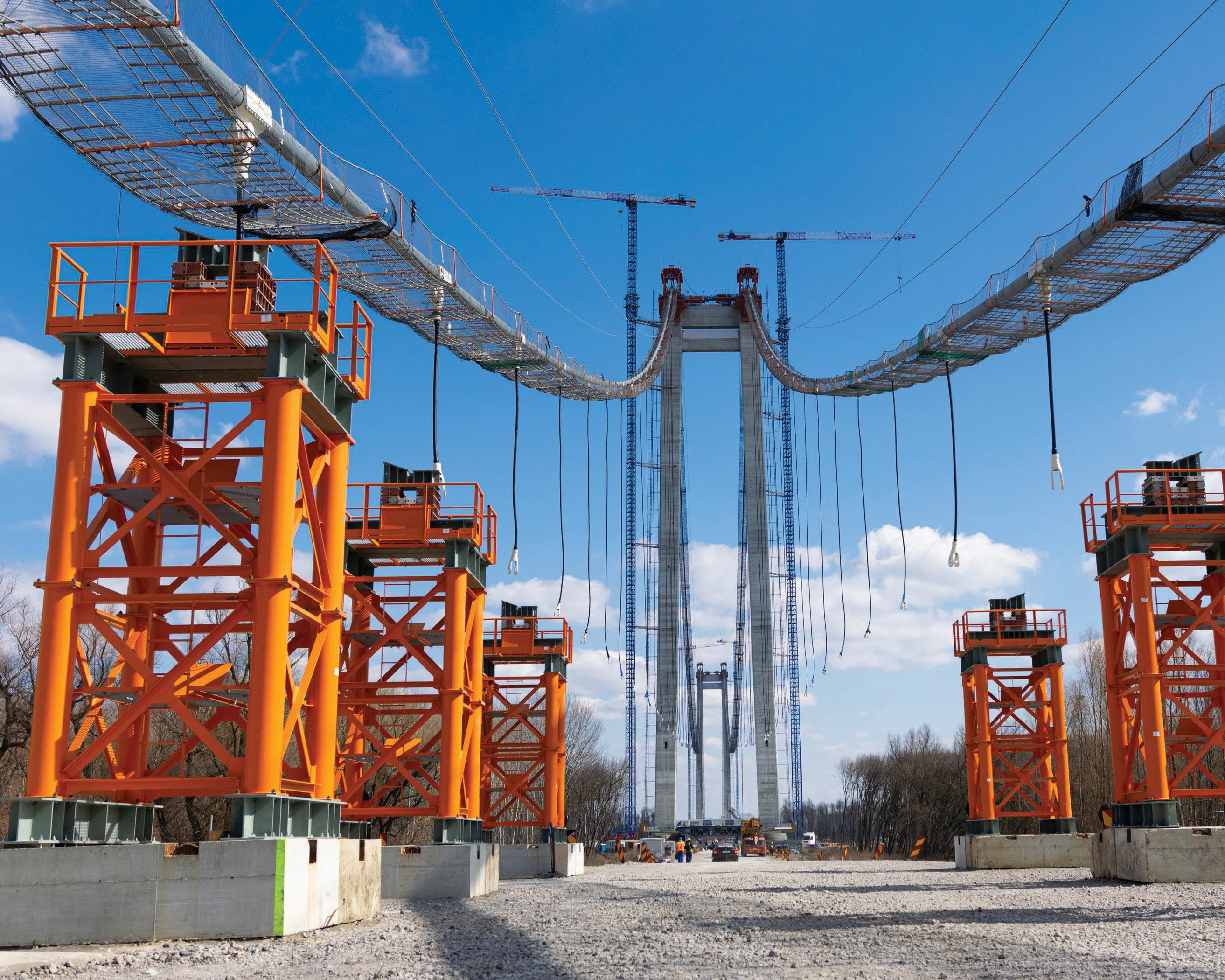
load can be found by reading off the ultimate load (2,700 kips or 12,000 kN) on the load-settlement curve at 0.1D and applying an appropriate safety factor to derive the working load of 900 kips (4,000 kN). However, at 1.5 times the working load of 1,350 kips (6,000 kN), the settlement exceeded 0.6 inch (15mm), which is not allowed by the same code. If 450 kips (2,000 kN) were to be taken as the working load, the settlement at 670 kips (3,000 kN), at 1.5 times, is less than 0.6 inch (15mm), which satisfi es the settlement requirement. Note from Figure 5 that the PL/AE line provides a very crude under-estimation of the settlement at low loadings. It appears that a 46-foot (14m) pile is possible. A quick calculation with assumed correlated shaft resistance and end-bearing values shows that a 46-foot (14m) pile is possible if a relatively high shaft resistance is used. erefore, it is necessary to compare against actual shaft resistance and endbearing obtained from an instrumented load test to verify that such values are indeed achievable. Similarly, the pile’s actual 1.5 times working load settlement should be checked.


Numerical simulations are often a valuable and powerful tool to gain insights into a problem and examine “what-if” scenarios that are impossible or impractical to perform in real-life situations. One example is the simulation of pile behavior under loads. It is possible to obtain reasonable shaft resistance and end-bearing values from a numerical model. Pile settlement can be readily calculated using numerical simulations, even with layered soils, which would be tedious to carry out by hand. With software, mathematical manipulations and number crunching are relegated to the back end. What is required is proper problem definition and the ability to capture the pertinent and peculiar features of a problem prominently and meaningfully in a model. A graphical interface provides immediate visual feedback on how the soil and pile behave. In addition, a qualitative examination of the displacements, load, stress, strain, and plastic point plots is often useful in deciphering whether a model responds or performs within expectations.
However, it is very easy to make mistakes when running a computer model, including arithmetic or other input errors. Moreover, numerical results generated are very much dependent on the input, such as boundary conditions, constitutive models, strength and deformation parameters, selection of interface thicknesses, etc. Deep scrutiny into the


input is necessary before relying on or trusting the output or numerical value for any critical design decision. erefore, it is often good practice to carry out benchmarking (against known or established results) and sensitivity studies (by varying key parameters within a range) to ensure numerical simulations do not produce results that defy logic and science. Despite convincing results from any numerical simulation, actual site measurements remain an instrumental part of pile design that should not be overlooked.
■






Hee Yang Ng is a Principal Engineer with a building control agency in the Asia-Pacific region.
single-source provider for restoration,
and
protection
 By Kelly Cobeen, S.E.
Designers using the 2022 Edition of the ASCE/SEI standard
Minimum Design Loads and Associated Criteria for Buildings and Other Structures (ASCE/SEI 7-22, ASCE, 2022) will find significant changes to the seismic design of diaphragms and their chords and collectors: a new diaphragm design methodology added, an existing methodology expanded, significant changes affecting bare steel deck diaphragms, and more. This leaves the user needing to choose between three methods of diaphragm seismic design and needing to incorporate other updates into their designs. The changes were generated from research and code development efforts that go back years, with contributions from many, including research and guideline development teams and the NEHRP and ASCE 7 update participants. This article provides an overview of these changes to diaphragm seismic design from the designer’s perspective.
The three diaphragm design methods found in ASCE/SEI 7-22 are the traditional design method of Section 12.10.1 and 12.10.2, the Alternative Design Provisions for Diaphragms including Chords and Collectors (alternative design provisions) of Section 12.10.3, and the Alternative Diaphragm Design Provisions for One-Story Structures with Flexible Diaphragms and Rigid Vertical Elements (alternative RWFD design method) of Section 12.10.4. The tra ditional design method of Section 12.10.1 and 12.10.2 has been
Table 1. Overview of the three available diaphragm seismic design methods. Method and ASCE/SEI
Figure 1. Concrete or masonry wall “big box” building, a common occurrence of the building type addressed by the alternative RWFD design method. Credit: Schnitzer Properties/VLMK Engineering + Design.
used with only minor changes since the 1980s; this was the only diaphragm design method available in building codes until ASCE/ SEI 7-16 (ASCE/SEI, 2017). When using the traditional design method, diaphragm design forces are determined based on the seismic design parameters for the vertical elements of the seismic force-resisting system without consideration of the effect of the
7-22 Section Number of Stories Permitted Diaphragm Systems Included Comments
Traditional Sections
12.10.1 and 12.10.2
Alternative Design Procedure Section 12.10.3
Any
Alternative RWFD Design Method
12.10.4
Any
Cast-in-place concrete
Precast concrete
Wood structural panel
Bare steel deck
Concrete-filled
Not permitted for precast concrete diaphragms in SDC C through
design forces are determined using seismic design
vertical elements
Wood structural panel
steel deck
limitations
7-22 Section
diaphragm system on the response of the structure. This method is permitted for all structures, except precast concrete diaphragms in Seismic Design Categories (SDCs) C through F.
The alternative design provisions of Section 12.10.3, first intro duced in ASCE/SEI 7-16, explicitly recognize and account for the effect of diaphragm ductility and displacement capacity on the diaphragm design forces. This is accomplished by introducing a diaphragm design force reduction factor, R s. Section 12.10.3 provisions restrict neither the number of stories nor the building configuration; however, diaphragm construction is limited to the diaphragm systems expressly noted within those provisions: Castin-place concrete, precast concrete, bare steel deck, concrete-filled steel deck, and wood structural panel diaphragms. The alternative design provisions are mandatory for precast concrete diaphragms in structures assigned to SDC C, D, E, and F. It is optional for all other diaphragm types and SDCs.
The alternative rigid wall flexible diaphragm (RWFD) design method of Section 12.10.4 introduces diaphragm seismic design provisions for one-story structures combining flexible diaphragms with rigid vertical elements. This seismic design methodology, new to ASCE/SEI 7-22, specifically recognizes that the seismic response of these structures is dominated by the dynamic response of, and inelastic behavior in, the diaphragm. While the most common occur rences of this structure type are the concrete tilt-up and masonry “big-box” buildings (Figure 1), this section’s rigid vertical element terminology recognizes a broader range of vertical elements for which this methodology is permitted to be used. The primary use of Section 12.10.4 provisions is intended for structures with dia phragm spans exceeding 100 feet; however, use for structures with diaphragm spans less than 100 feet is permitted.
Table 1 provides an overview of the three diaphragm seismic design methods to help the designer choose a method.
The unifying concept behind both alternative diaphragm design methods is the recognition of the diaphragm system’s influence on the seismic response and performance of the diaphragm and, in some cases, the building. The changes originate from research, including both testing and numerical studies. The new design methods are thought to better reflect diaphragm dynamic response, reflect diaphragm ductility and deformation capacity, and provide better diaphragm performance, sometimes at a lower construction cost. While the traditional design method remains available for
most structures, designers are encouraged to use the new methods where applicable.

The alternative design provisions developed out of two distinct efforts. One was a significant multi-university precast concrete research project, Development of a Seismic Design Methodology for Precast Concrete Diaphragms (Fleishman et al., 2013), addressing the alignment of diaphragm seismic forces with diaphragm deformation capacities. This project included significant testing and numerical studies that resulted in redefining the design and detailing of precast concrete diaphragms. Included was the definition of categories of precast connectors based on ductility and seismic design forces appropriate to each category. Concurrently, the Diaphragm Issue Team for the 2015 NEHRP Provisions (FEMA, 2015) worked with collected diaphragm seismic force data from testing and numerical studies to investigate both vertical distribution of diaphragm seismic forces and the influence of diaphragm deformation capacity on the seismic forces. The results of these two efforts were combined in the 2015 NEHRP Provisions and ASCE/SEI 7-16. Two significant steel research projects contributed to the expansion of the alternative design provisions in the 2020 NEHRP Provisions (FEMA, 2021a) and ASCE/SEI 7-22. The Steel Diaphragm Innovation Initiative (www.steeli.org) (Avellaneda et al., 2019; Eatherton et al., 2020; Foroughi et al., 2019; Wei et al., 2019) sought to broadly advance the seismic performance of steel floor and roof diaphragms, while Advancing Seismic Provisions for Steel Diaphragms in Rigid-Wall Flexible-Diaphragm Buildings (Schafer, 2019) also contributed. This research expanded the alternative design provisions to include bare and concrete-topped steel deck diaphragms.
The alternative RWFD design method was developed from a Building Seismic Safety Council building code simplification project that studied code simplification around the design of RWFD buildings. It had long been recognized that code equivalent lateral force (ELF) seismic design forces did not properly reflect the seismic response of this building type. Substantial numerical studies supplementing available building response data (Koliou et al., 2015a, 2015b) led to the development of the new design direction found in Seismic Design of Rigid Wall-Flexible Diaphragm Buildings: An Alternate Procedure (FEMA P-1026, 2015 and 2021). This new methodology was developed into ASCE/SEI 7 design provisions through the efforts of the NEHRP PUC and the ASCE/ SEI 7 standard committee. Subsequent work from the project Advancing Seismic Provisions for Steel Diaphragms in Rigid-Wall Flexible-Diaphragm Buildings has expanded the methodology to include bare steel deck diaphragms.
The mandate for the use of Section 12.10.3 for precast diaphragm systems in SDC C through F is based on the research by Fleischman et al., indicating that improved earthquake performance can be attained through recognition of the ductility and deformation capacity based on diaphragm detailing used. Without the Section 12.10.3 provisions for precast diaphragms, the seismic performance might be less than that targeted by the NEHRP Provisions and ASCE/SEI 7. The derivation of seismic design forces when using the alternative design provisions involves dividing near-elastic forces by a diaphragm-design force reduc tion factor (diaphragm-specific R-factor, Rs). Values for the Rs factor are found in Table 2 ( page 29), differentiated by detailing criteria noted as the Elastic, Basic and Reduced Design Option. The Rs values range from 0.7 to 1.4 at the lower end of tabulated values. Using alternative design provisions will increase precast concrete diaphragm seismic design forces to near-elastic levels, a significant departure from past practice. Following the development of alternative design provisions and the mandate for use with precast concrete diaphragms, the concrete industry went on to identify a new category of diaphragms constructed with precast concrete elements, designated as “cast-in-place concrete equivalent precast diaphragms,” found in ASCE/SEI 7-22 Section 14.2.2.1. This diaphragm type uses either a non-composite cast-inplace diaphragm over precast sections or a precast diaphragm with cast-in-place closure strips. For this diaphragm type, using the ASCE/ SEI 7-22 alternative design provisions is not mandated, allowing the traditional design method of Sections 12.10.1 and 12.10.2 to be used. This is permitted because this diaphragm type does not rely on the connectors studied in the Fleishman research to transfer seismic forces between precast sections.
The following briefly describes the main concepts behind the two alternative diaphragm design methods. The reader is referred to detailed discussions in the 2015 and 2020 NEHRP Provisions and the commentary to ASCE/SEI 7-16 and ASCE/SEI 7-22.
Figure 2a. Design acceleration coefficients defining the vertical distribution of diaphragm seismic forces when using the alternative design provisions of Section 12.10.3. Credit: ASCE/SEI 7-16.

Two primary concepts drive the alternative design provisions. First is the determination and vertical distribution of diaphragm seismic forces based on an assumption of near-elastic diaphragm response. This was driven by a significant body of diaphragm force information collected from testing and numerical studies. Figure 2a illustrates the design acceleration coefficients defining the vertical distribution of diaphragm seismic forces when using the alternative design provi sions of Section 12.10.3 of ASCE/SEI 7, and Figure 2b illustrates one of the items of data used to derive the vertical distribution. The second concept is the division of the near-elastic diaphragm forces by an Rs diaphragm design force reduction factor, which reduces the diaphragm forces based on the ductility and deformation capacity of the diaphragm system. These factors also were derived from testing and numerical studies.
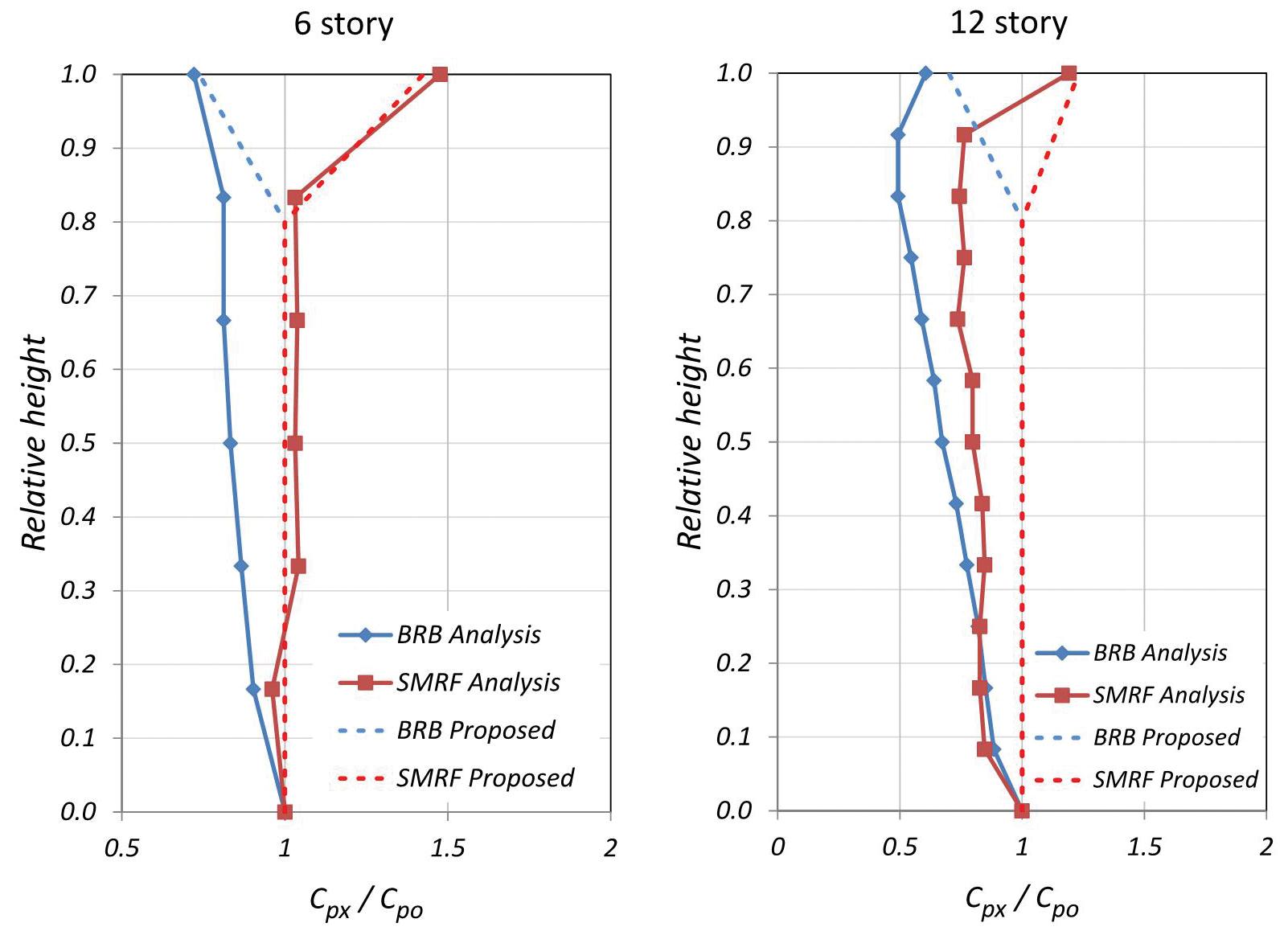
The alternative RWFD method is driven by the long-standing recognition that large footprint budlings with rigid vertical ele ments and flexible diaphragms have seismic responses driven primarily by the flexible horizontal diaphragm rather than the rigid vertical elements. For the RWFD structure shown in Figure 3a , Figure 3b graphically illustrates that the rigid vertical elements’ seismic response falls at the design spectrum’s plateau. In contrast, the response of the diaphragm falls on the descending curve. The traditional diaphragm design method ignores this behavior, calculating the diaphragm seismic forces as a function of the system used for the rigid vertical elements. The alternative RWFD design method incorporates this known behavior into the diaphragm design provisions.
Figure 2b. Data considered in establishing the vertical distribution of diaphragm seismic forces for the alternative design provision of Section 12.10.3. Credit: FEMA P-1050-1.
In addition to developing more realistic seismic design forces, the alternative RWFD provisions incorporate a method of achieving better seismic performance. This is accomplished by designing a boundary zone for amplified shears and rein forces the diaphragm zones alongside the vertical elements where the highest forces and inelastic demands occur. As a result, numerical studies have demonstrated that inelastic behavior will be better distributed through the interior portions of the dia phragm, where the diaphragm fastening is reduced.
To date, a limited number of design examples have been developed to illustrate the effect of the alternative design provisions. There are several examples in NEHRP Recommended Seismic Design Provisions: Design Examples, Training Materials, and Flow Charts (FEMA P-2192 V2, 2021). In these examples, diaphragm design forces using the alternative methods are generally the same or less than the traditional method at most building stories but often increased at the top story. One exception is notably increased diaphragm design forces when using the alternative design provisions for bare steel deck diaphragms that do not meet new AISC special seismic detailing provisions.
While there are several other diaphragm design changes, one of significance is the addition in AISI S400 Section F3.5.1 (AISI, 2020) of prescriptive and performancebased special seismic detailing requirements for bare steel diaphragms. The prescriptive AISI S400 require ments, provided in Table 3 , have been identified through testing to provide good hysteretic response, including retaining post-peak cyclic load capacity. In both alternative diaphragm design methods, the seismic design force for the diaphragm will be significantly affected (by a factor of 2.5 to 3) by the designer’s choice to meet or not meet these AISI requirements.
Figure 3a. Illustration of seismic forces applied to a RWFD structure. Courtesy of FEMA P-1026.
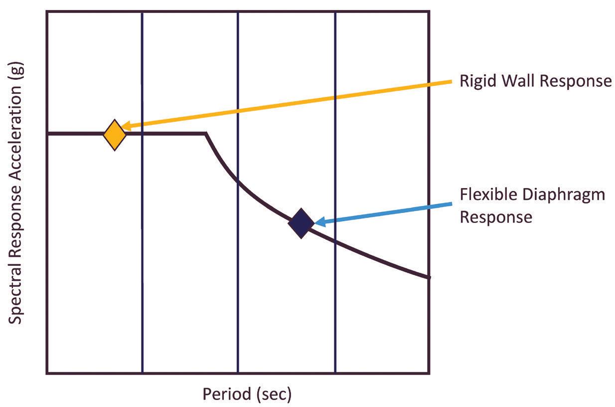

It is recommended that designers interested in further information begin with the extensive commentaries provided with ASCE/SEI 7-16, ASCE/SEI 7-22, and the 2015 NEHRP (FEMA P-1050) and 2020 NEHRP (FEMA P-2082) Provisions. NEHRP Recommended Seismic Design Provisions: Design Examples, Training Materials and Flow Charts (FEMA P-2192 V2, 2021) and Seismic Design of Rigid Wall-Flexible Diaphragm Buildings: An Alternate Procedure (FEMA P-1026, FEMA, 2021) are helpful as well.■
Figure 3b. Illustration of seismic design spectrum with the period of the diaphragm and vertical elements differentiated.
Detailed references are included in the PDF version of the online article at STRUCTUREmag.org

Kelly Cobeen is a Principal with Wiss, Janney, Elstner Associates, Inc. (kcobeen@wje.com).
Table 3. Prescriptive special seismic detailing requirements for steel deck diaphragms (Based on AISI S400 Section F3.5.1).
1The steel deck panel type shall be 36 inches wide, 1.5 inches deep wide rib (WR), 6 inches pitch deck.
2The steel deck base steel thickness shall be greater than or equal to 0.0295 inch and less than or equal to 0.0598 inch.
3The steel deck material shall conform to Section A.3.1.1 of AISI S100.
4 The structural connection between the steel deck and the supporting steel member (with minimum thickness of 1⁄8 inch) shall be limited to mechanical connectors qualified in accordance with AISI S400 Section F3.5.1.1.
5 The structural connection perpendicular to the steel deck ribs shall be no less than a 36/4 pattern (12 inches on-center) and no more than a 36/9 pattern (6 inches on-center) with double fasteners in the last panel rib.
6 The structural connection parallel to the steel deck ribs shall be no less than 3 inches and no more than 24 inches and shall not be greater than the sidelap connection spacing.
7 The sidelap connection between steel decks shall be limited to #10, #12, or #14 screws sized such that shear in the screws is not the controlling limit state or connectors qualified in accordance with AISI S400 Section F3.5.1.2.
8The sidelap connection shall be spaced no less than 6 inches and no more than 24 inches.


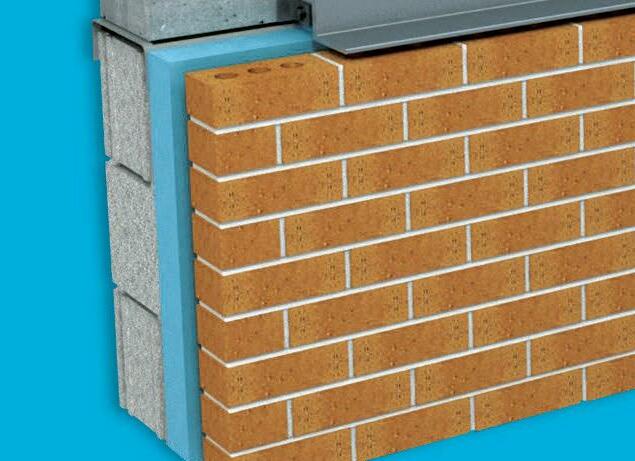

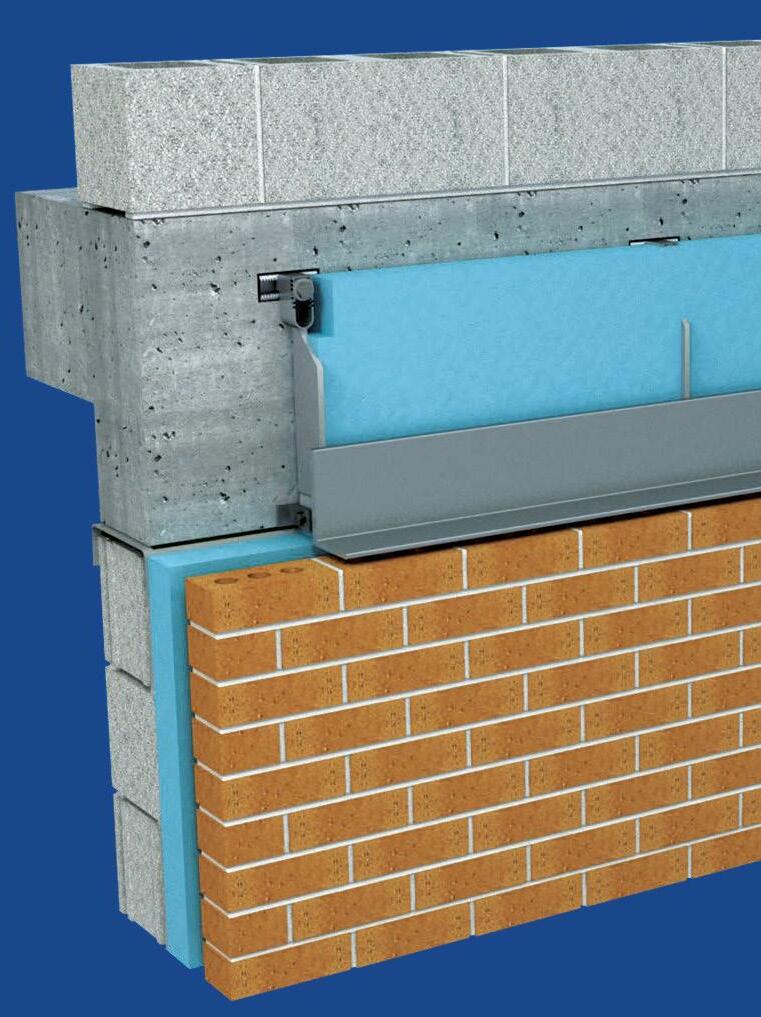
Recent updates and evolving energy code requirements for thermal performance demand more continuous insulation in the building envelope. Reduce thermal transfer with our groundbreaking, custom-designed, engineered, and fabricated brick veneer support system. Our system reduces thermal bridging in shelf angles and allows for continuous insulation to improve the energy efficiency of your building. Available in Bracket Style (above) and Fin Style (right). For more info visit, www.h-b.com/tbs
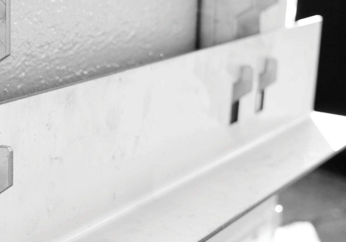
This quarterly article addresses some of the questions received about structural stan dards developed by the Structural Engineering Institute (SEI) of the American Society of Civil Engineers (ASCE). Following are some ques tions received by SEI and responses to clarify the provisions. Questions from engineers, building officials, and other design profes sionals are often considered to develop future standard editions.

When was the first ASCE 7 standard published?
Q: I am researching historical document requirements, and on one of my projects, it referenced ANSI 58.1 for roof, wind, and snow loads. The ANSI document seems to have been replaced by the ASCE/SEI 7 standards book. Is this correct? If so, what year did that happen?
A: Yes, the final ANSI version of A58.1 Minimum Design Loads for Buildings and Other Structures was published in 1982 and was replaced in 1988 by ASCE 7 Minimum Design Loads for Buildings and Other Structures as ANSI/ASCE 7-88. ASCE, and then SEI, has been developing ASCE 7 ever since!
How are environmental temperature changes supposed to be included in the load combinations for strength design?
Q: According to ASCE/SEI 7-22 Section 2.3.4, “Where the structural effects of self-straining forces T (environmental temperature changes) are expected to adversely affect structural safety or performance, T shall be considered in combination with other loads.” And the Commentary states, “Self-straining forces and effects should be calculated based on a realistic assessment of the most probable values rather than the upper bound values of the variables. The most probable value is the value that can be expected at any arbitrary point in time.” Two combinations are presented, both involving only Dead and Live Load. Therefore, is it necessary to combine temperature load with wind load? If so, which are the combination factors? Furthermore, is it necessary to combine temperature load with wind load AND live load? If so, which are the combination factors?
A: With regards to the load combinations in Commentary C2.3.4, an example is given for when T is the principal load and when it is the arbitrary point-in-time load (see Table C2.4-1) so that
• T is the principal load in this combination: 1.2D + 1.2T + 0.5L, and
• T is an arbitrary point-in-time in this combination:
1.2D + 1.6L + 1.0T.
This section also states, “These combinations are not all-inclusive, and judgment is necessary in some situations. For example, where roof live loads or snow loads are significant and could occur simultaneously with self-straining forces and effects, their effect should be included. The design should be based on the load combina tion causing the most unfavorable effect.”
This commentary refers to the load combina tions in Section 2.3.1, where T can be added to other load combinations as appropriate.
What is the difference between NAVD88 and MHW in the ASCE Tsunami Design Geodatabase?
Q: My company has a design project in Hawaii. It involves exterior piping and supports that fall within the tsunami inundation zone. I am trying to identify the water depth at our design location. The ASCE Tsunami Design Geodatabase online tool indicates a Mean High Water (MHW) runup elevation, but no NAVD88, North American Vertical Datum of 1988, runup elevation. How can the MHW value be related to the NAVD88 datum, and why is this not included in the Geodatabase?
A: The NAVD88 vertical datum is only available for the North American contiguous states. All figures in ASCE 7-22 have been updated to include MHW. Alaska and Hawaii have no NAVD88 references but rely on Mean High Water, MHW. Therefore, the ASCE Tsunami Geodatabase only lists elevations relative to MHW for Hawaii. You can use the geodatabase to determine your site’s elevation relative to MHW. Alternatively, you can use other sources for the elevation. Once you run the Energy Grade Line Analysis (and site-specific inundation modeling, if required), the flow depth determined from those analyses will be relative to the actual ground elevation at your site.
Where are the underlying data for the seismic values in the ASCE 7 Hazard Tool?
Q: Would you please direct me to the raw data used to develop the maps in ASCE 7-22 Chapter 22 shown in the ASCE 7 Hazard Tool? Is it still the same data used for ASCE 7-10 or ASCE 7-16?
A: The seismic values in the ASCE 7 Hazard Tool are from the United States Geological Survey (USGS) Webservice and are included in ASCE 7-22 Chapter 22. They are available at https://earthquake.usgs.gov/ws/designmaps using the 2020 NEHRP, National Earthquake Hazards Reduction Program, link. The USGS will be adding a link directly for ASCE 7-22 as well. Additionally, per the link provided in ASCE 7-22 (www.usgs.gov/programs/earthquakehazards/hazards), the USGS has developed information to provide more
background information on their process and the data. Furthermore, the USGS explains how the seismic hazard models are updated each cycle to develop the underlying data used in each cycle of ASCE 7. And no, the data for ASCE 7-10 is not the same as for ASCE 7-16 or ASCE 7-22.
How is wind load on elevated building components calculated?
Q: Which section of ASCE 7 should be used for the wind load on a stair landing connected to a raised building? If the landing is flushed with the floor of the elevated building, should it be designed as a canopy?
A: Elevated buildings are now covered in the ASCE/SEI 7-22 version of the Standard.
Section 30.3.2.1 Bottom Horizontal Surface of Elevated Buildings is the best resource to determine the wind pressures on this stair landing. When do glazed openings need to be designed for tornado loads for Essential Facilities?
Q: If an Essential Facility in a Tornado-Prone region is determined to have tornado speeds, VT, that do not require design for tornado loads per Section 32.5.2 in ASCE 7-22, do the glazed openings for that facility still need to be protected in accordance with 32.12.3?

A: e answer is no. Per Section 32.5.2 Design For Tornado Loads Not Required, if VT < 60 mi/h, design for tornado loads shall not be required.
Is fiber mesh reinforcement prohibited in Coastal High Hazard Zones per ASCE 24?
Q: What is the requirement in ASCE 24-14 for fiber mesh reinforcement in concrete slabs in Coastal High Hazard Zones? e
provisions appear to be a blanket prohibition on any type of reinforcement in these ground slabs. Would you please clarify where fiber mesh is permitted?
A: ASCE 24-14 Section 9.3 Concrete Slabs permits two slab options in Coastal High Hazard Areas: 9.3.1 for frangible slabs and 9.3.2 for self-supporting structural slabs. For frangible slabs, reinforcing shall not be used. For self-supporting slabs, there is no restriction imposed by ASCE 24-14 on reinforcement type. e intent of ASCE 24-14 section 9.3 option 1, such as for frangible slabs, is to promote failure of a slab in such a way that an undermined slab would break into small pieces. Micro-fi ber reinforcement could meet this goal since its use is intended to prevent small cracks in the slab surface and since its use would not likely prevent the breakup of the slab if undermined. However, using fi berglass mesh or similar as a replacement for reinforcing steel or welded wire mesh may prevent this performance goal from being reached.
e Authority Having Jurisdiction would need a closer review, depending on the exact fi ber mesh proposed. A fi ber mesh that prevents slab breakup would not satisfy ASCE 24-14 Section 9.3, option 1. However, local or state fl oodplain management regulations may limit the use of option 2 in some circumstances, and Section 6.9 of the National Flood Insurance Program (NFIP) Technical Bulletin 5-20 Free of Obstruction Requirements discusses the same two options. ■
If you have a question you want to be considered in a future issue, send it to sei@asce.org with FAQ in the subject line. Visit asce.org/sei to learn more about ASCE/SEI Standards.


is article’s information is provided for general informational purposes only and is not intended in any fashion to be a substitute for professional consultation. Information provided does not constitute a formal interpretation of the standard. Under no circumstances does
ASCE/SEI, its affiliates, officers, directors, employees, or volunteers warrant the completeness, accuracy, or relevancy of any information or advice provided herein or its usefulness for any particular purpose.
ASCE/SEI, its affiliates, officers, directors, employees, and volunteers expressly disclaim any and all responsibility for any liability, loss, or damage that you may cause or incur in reliance on any information or advice provided herein.
Laura Champion is a Managing Director of the Structural Engineering Institute and Global Partnerships at the American Society of Civil Engineers.
Jennifer Goupil is the Director of SEI Codes, Standards, and Technical Initiatives at the Structural Engineering Institute of the American Society of Civil Engineers.
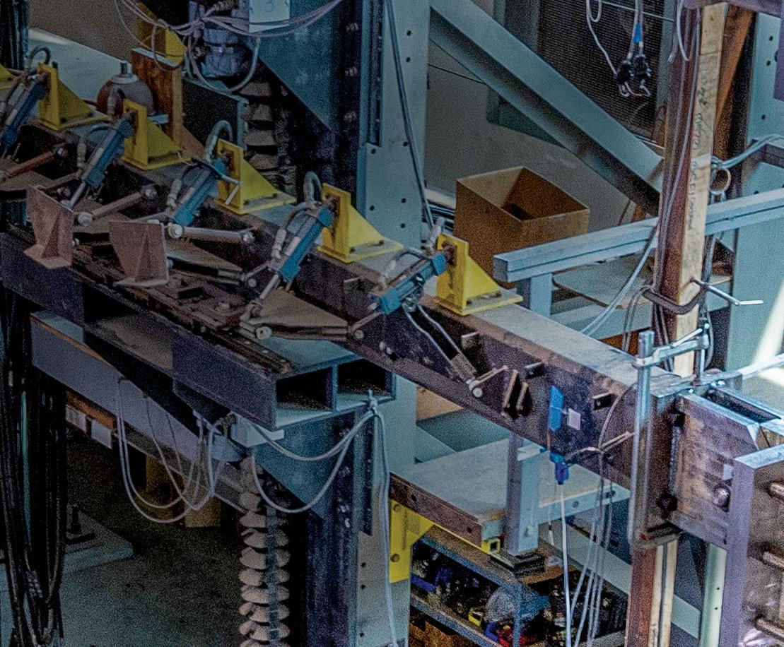




Verify your project design with full-scale, application-specific testing. In concrete and masonry, the only true strength is tested strength. That’s why the Simpson Strong-Tie and Structural Technologies alliance is committed to full-scale product testing of Composite Strengthening Systems™ in a variety of applications. Our laboratories and facilities ensure products are rigorously tested and load rated for real-world, as-built conditions. It’s all part of a complete solution with innovative products, engineering services, and technical and field support. So whether you’re planning to strengthen, repair or design with concrete or masonry, you can move ahead with confidence. Set a solid foundation for success. To learn more about our testing capabilities and concrete and masonry solutions, visit go.strongtie.com/alliance or call (800) 999-5099.

Choose Champion Bridge Drain™ for your bridge environmental filtering strategy.
Champion Fiberglass Bridge Drain system is strong, durable and safely diverts accumulated rainwater and contaminants from bridge decking.
Made from strong fiberglass using epoxy resins for further strength, the Champion Fiberglass Bridge Drain system consists of straight lengths, fittings, non-metallic accessories and hangers that withstand harsh, corrosion-filled environments including gas, oil and salt.
Highway bridge projects benefit

championfiberglass.com




Dennis Nottingham, P.E., was a bridge builder. “I designed a lot of bridges, the big ones. The Yukon. The Gulkana. I worked on every single bridge – construction bridges, access bridges – on the Trans-Alaska Pipeline in some form or another,” Nottingham said during his company’s 40th-anniversary celebration in 2019 in Anchorage. His Hall of Fame biography credits Nottingham with more than 300 bridge designs in Alaska.
Bridges brought Nottingham to Alaska, and bridges are what Nottingham will be immortalized for in Alaska. He was enshrined in 2015 as “The Bridge Builder” into the Northern Innovators Hall of Fame by the Alaska Statewide Committee for Research.
William Dennis Nottingham died on March 6, 2022. He was 84 years old. Nottingham will be remembered as one of Alaska’s most influential engineers.
After graduating from Montana State College with his master’s degree in civil/structural engineering, Nottingham worked for the State of Montana, designing bridges for the country’s fledgling Interstate Highway System under the Eisenhower Administration. He answered a local classified advertisement calling for bridge engineers to expand Alaska’s nascent road system, then moved to Juneau in 1962 for a job at the Alaska Department of Highways in its bridge design section. There he met Roy Peratrovich, Jr., the bridge design section squad leader.
“When I came up here, I had no concept of the opportunities that were ahead,” Nottingham said. “I came because I liked the outdoors.”
The situation suited him well. Nottingham and Peratrovich worked together at the state for 10 years and another seven in the private sector, designing iconic bridges such as the Gulkana River Bridge, Sitka Harbor Bridge, and Yukon River Bridge. The pair eventually partnered in their own consulting engineering firm startup in 1979, Peratrovich & Nottingham, Inc. Now known as PND Engineers, Inc., the firm proudly carries on its founders’ legacy of innovative engineering services and features offices in Anchorage, Juneau, Seattle, Washington; Portland, Oregon; Houston, Texas; and Vancouver, B.C.
The Sitka Harbor Bridge is arguably their most famous bridge because of its place in American history. In 1969, Peratrovich, the state’s design squad chief, and Nottingham, who performed design check and struc tural analysis for the project, designed the 1,255-foot-long bridge over the Sitka Channel, linking Sitka to Japonski Island. It is credited with being the first cable-stayed vehicular crossing in U.S. history.
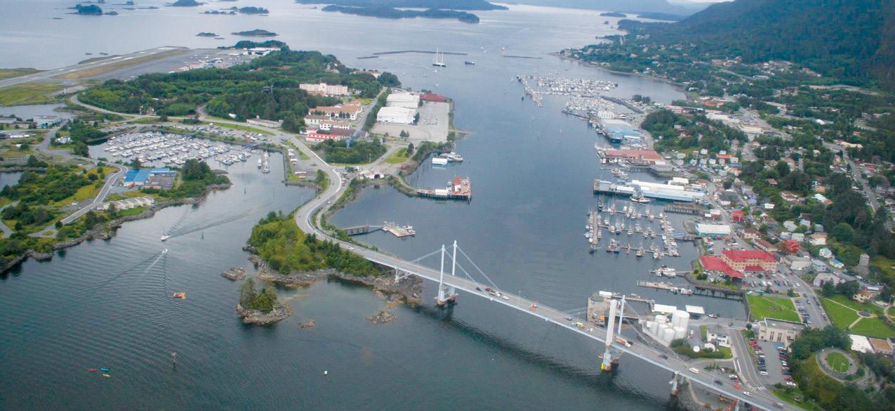
The bridge was recognized by the American Society of Civil Engineers Alaska Section as a State Historic Civil Engineering Landmark on September 11, 2022.
“There was so much deflection analysis that had to be made because you had different deflection capabilities at different points where the cable was attached,” Peratrovich recalled of the unprecedented design. “It was pretty complicated, but Dennis figured out a way to do it.”
During the 1970s, Nottingham was the lead designer for the 400-foot-long tied-arch Gulkana River pipeline bridge along the Richardson Highway in Southcentral Alaska, which used steel piles driven into permafrost, setting a new arctic engineering standard. The bridge was designed, fabricated, and constructed in six months – 15 days ahead of schedule. Nottingham was also the lead designer for the 2,297-foot-long Yukon River Bridge along the Dalton Highway, approximately 135 miles northwest of Fairbanks. The largest bridge in Alaska at the time featured unprecedented aboveground twin oil and natural gas pipelines, a low-temperature steel box girder design, and is believed to be the first to include modern seismic design.
“Dennis was certainly a bridge designer. His first love was designing bridges, and they were beautiful bridges, too. Still, they were practical,” said consultant and former PND business partner William Gunderson, P.E., whose GUNDERBOOM™ technology also received interna tional acclaim in the late 1980s and early 1990s under the umbrella of PND’s research and development department. “I think Dennis’ biggest development was the OPEN CELL technology. There’s no question.” Nottingham won the prestigious NOVA Award from the Construction Innovation Forum in 1998 for PND’s proprietary OPEN CELL SHEET PILE™ (OCSP) bulkhead technology. PND, which holds multiple U.S. patents on the tech, has designed more than 200 OCSP systems valued at more than half a billion dollars since Nottingham pioneered the design in the early 1980s, with installations across the U.S. and internationally, including Bermuda, Canada, Guyana, Iraq, Philippines, and Russia.
In addition to his NOVA Award, Nottingham won 15 James F. Lincoln Arc Welding Foundation Awards for various projects during his 30-year career at PND, believed to be a U.S. record. He has held as many as nine U.S. patents. He won the Associated General Contractors of Alaska Hard Hat Award in 2004, an honor typically reserved for construction contractors.
Peratrovich left the following comment on Nottingham’s tribute wall on the Croxford Funeral Home website: “Dennis was my friend for nearly 60 years. Together we raised young families, hunted and fished, designed bridges and marinas, and founded a successful engineering firm. So many memories! RIP, sir.”■
Aaron Unterreiner is the Marketing Manager for PND Engineers, Inc. (aunterreiner@pndengineers.com).


The Lava Fire, one of the largest wildfires to scorch California in 2021, burned over 26,000 acres and prompted evacuations of at least 8,000 residents. Sparked by a lightning strike, the fire burned for just over two months around the wooded slopes of Mt. Shasta. e extensive fire heavily damaged multiple structures, including Union Pacific Railroad’s Dry Canyon Bridge and nine miles of track near Weed, California.
On June 28, 2021, the Dry Canyon bridge, which stands 150 feet tall and spans approximately 1,140 feet across a remote scenic valley, was closed due to the damage. While still combatting the fire in late June, Union Pacific Railroad Company (UPRR) engaged Modjeski and Masters (M&M) to assess the damage and recommend repairs to the steel-girded bridge.

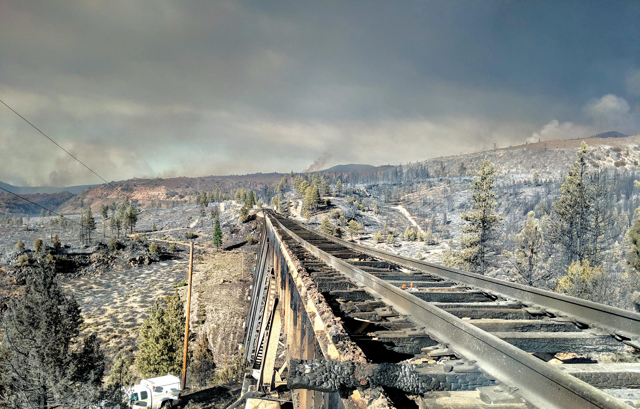
e bridge, constructed in 1926, has 19 spans that vary in length. e spans are 70 feet 4 inches long from Abutment 1 to Bent 2 and Bent 19 to Abutment 20, 80 feet long for odd-numbered spans 3 through 17, and 40 feet long for even-numbered spans 2 through 18. e deck is comprised of a ballast deck with a timber ballast pan and curb. e superstructure also consists of steel girders supported by steel bents forming towers founded atop concrete pedestals. Unfortunately, the closely spaced ballast pan timbers and track ties made the bridge vulnerable to wildfires.
e first goal was to understand the extent of the damage and degree to which each steel span was deformed. M&M established three categories of damage to assess each steel deck plate girder. e categories were:
• Category One – e span was generally straight with minor distortions or was unaffected.

• Category Two – e span was noticeably deformed and distorted but within allowable limits for heat straightening.
By Matthew Miller, P.E.• Category ree – e span was severely deformed and outside of the limits for heat straightening or would be uneconomical to repair and would need to be replaced.
During the inspection, the team reviewed the external physical damage to the girders on each span, along with the cross-frame and lateral members. e team then reviewed the fitness and structural integrity of the fire-exposed steel by looking at the steel type and grade and looking for heavy pitting, heavy dark grayscale, and any remnants of the original lead-based paint. ese were signs that the metal had reached the limit of the transformation temperature.
Following the assessment, M&M concluded that all 19 spans needed to be repaired or replaced. Nine 40-foot-long (12.2m) spans met the criteria for Category Three and were replaced with safety stock spans of similar size. In contrast, the remaining spans fell into Category Two and were deemed salvageable through heat straightening.
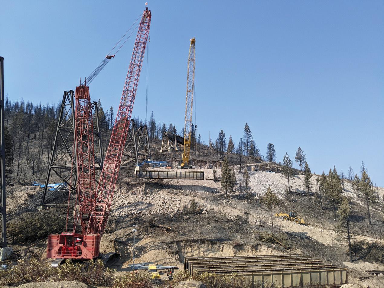
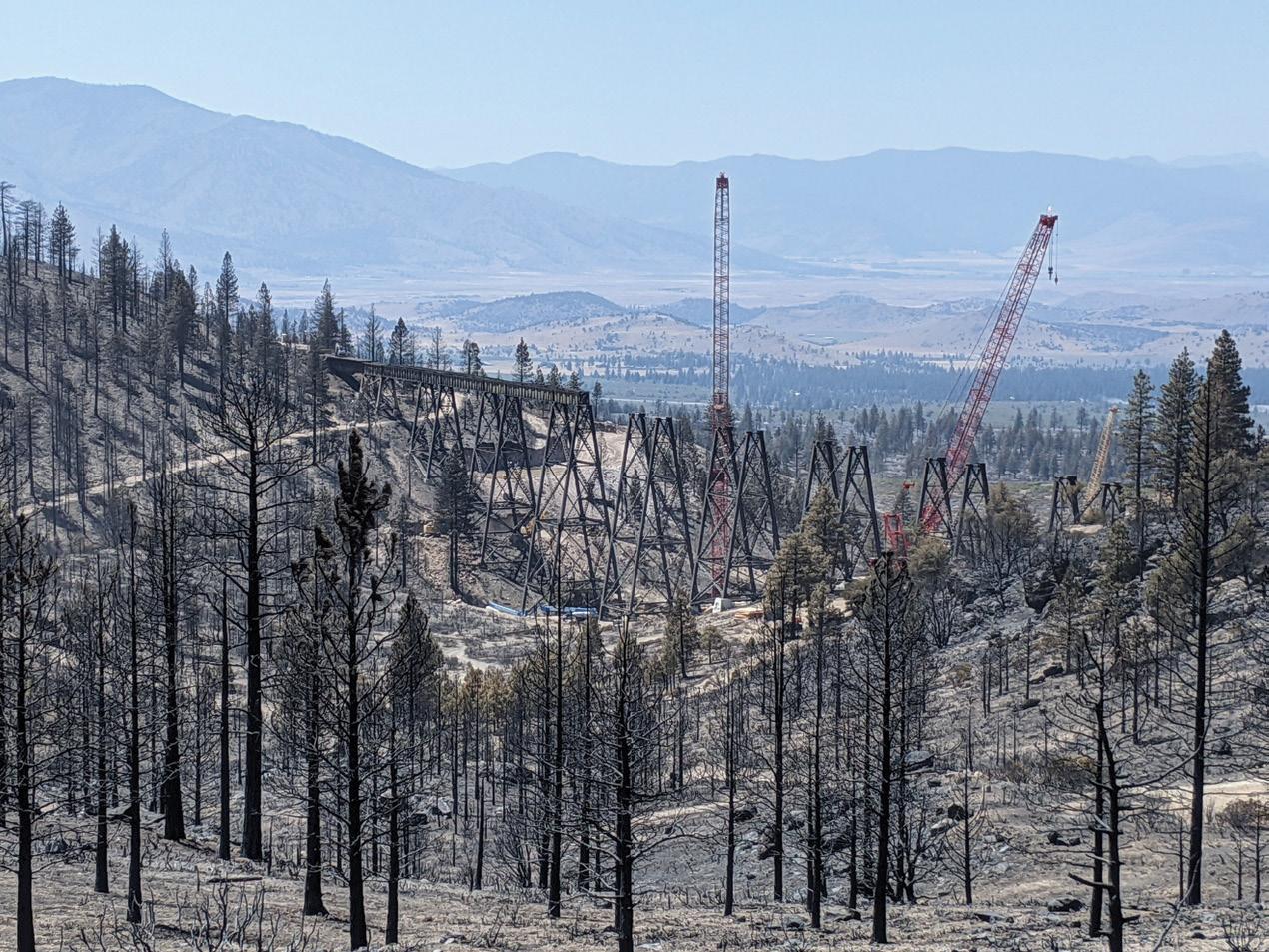
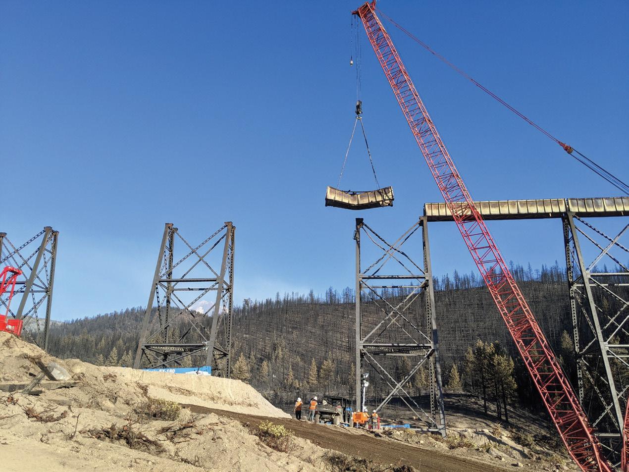
Heat straightening is a relatively uncommon but effective and effi cient tool for repairing damaged steel members. However, as much as science, there is an art to heat straightening.
Heating techniques to shape or straighten structural steel draw their origins from the initial days of welding. During that time, it was discovered that the heat from welding during the fabrication of steel members caused distortions that followed a regular pattern. This occurrence spawned the idea of using carefully planned heating tech niques to reverse the distortions caused by welding and other damage. Heat straightening is not always an appropriate repair method, and its use must be considered in combination with the level of damage observed, the steel type, the economics of replacement versus repair, and the specific member damaged. Research has shown that heat straightening is a viable option without significantly affect ing the material properties of mild steel for strain ratios of 100 or less. Additionally, the number of damage and repair cycles affects the steel’s material properties. Damaged areas should not be heat straightened more than two times.
The heat straightening procedure used in this project is a controlled application of heat in planned and specific patterns to damaged regions of the steel in repetitive heating and cooling cycles to gradu ally straighten the damaged material. Straightening the steel relies primarily on internal forces to produce upset during the heat ing phase and contraction during the cooling phase with external restraints to aid the work. The heating and cooling phases produce a thermal gradient with each cycle, leading to a gradual straightening or shaping trend. As the heat is applied, the temperature decreases through the thickness of the material. The cooled material ahead of the heated area constrains thermal expansion. Because of the thermal gradient at the heated location, more upsetting occurs on the hotter side of the plate. During cooling, the hotter side contracts more than the cooler side, creating disproportional movement on either side of the plate. External forces can be applied to magnify the movements to aid in this process.
Several conditions must be met to perform heat straightening safely and effectively:
• The applied temperature must not exceed the transformation temperature of approximately 1300 degrees Fahrenheit.
• Stress produced by any applied external forces does not exceed the yield stress of the steel in its heated condition.
• Only the regions in the vicinity of the plastically deformed zones are heated.
Several fundamental heating patterns exist to perform heat straight ening, including Vee Heats (used to straighten strong access bends), Edge Heats (used for smooth, gentle bends), Line Heats (used to repair a bend in a plate about its weak axis), Spot Heats (used to repair localized damage such as bulges, dents, bellies, or dishes in a plate element), and Strip Heats (used to remove a bulge in a plate element or complement a Vee Heat). Most of these fundamental heating patterns were used to straighten the girders for the Dry Canyon project. Specifically, Vee Heats and Line Heats to remove sag and sweep in the girders, and Strip Heats and Spot Heats to remove bulges and localized damage in the girder webs.
The temperature must be controlled during the heat straightening process. An oxyacetylene torch with single orifice tipped torches was used to heat the steel. Multiple methods can be used to monitor the temperature of the steel during heating, such as visual observation of the color of the steel, special temperature crayons, and infrared electronic temperature sensing devices.
For the steel type on the Dry Canyon project, the maximum applied temperature is 1,200 degrees. Visual observation was the method used to monitor the temperature of the steel. Once the steel is heated and the flame is removed from the heated area for a three to five-second “soak time,” the color of the heated steel is observed against the fol lowing color-to-heat scale (temperature values are approximate and are given in degrees Fahrenheit):
• Faint Red – 460 degrees

• Blood Red – 1,050 degrees
• Dark Cherry (ideal color) – 1,175 degrees
• Medium Cherry – 1,250 degrees
• Cherry or Full Red – 1,375 degrees
In the case of the Dry Canyon Bridge, the steel comprising the girders is acceptable for heat straightening, the strain ratios for the heat straight ened members were within 100 times the yield strain, and no other heat straightening repairs had been performed on the structure. Further, replacing the existing girders with new girders was uneconomical.

UPRR engaged a team of three construction contractors – ZA Construction, Arc-Rite Welding and Fabrication, LLC, and Dan. R. Dalton, Inc. – to make around-the-clock repairs and expedite the bridge reopening.
ZA Construction led site preparation by removing the existing spans, erecting the repaired or replaced spans, installing deck, and selecting structural steel fabrication and installation methods. Arc-Rite was responsible for tower longitudinal and diagonal bracing installation, tower cap plate installation, and select steel repairs. Dalton, a heat straightening specialist, performed their own evaluation of the damage and was responsible for heat straightening and select steel repairs.
While heat straightening can typically be performed in-place, due to the complexity of repairing the spans over the canyon, each span was removed by crane and repaired on the ground. First, ZA Construction built a road across the steep, rocky terrain to bring the crew and equip ment to the remote site. ZA Construction then constructed four pads to hold the cranes, ranging from 200 to 600 tons in lifting capacity, to lower the bridge spans to the ground and stage them for repairs. Several unique and special challenges were encountered during the heat straightening repairs and subsequent erection of the girders. First,
during the heat straightening of the initial spans, it was discovered that the fire damage and heat straightening process had caused the spans to shorten a meaningful amount. Also, due to time constraints, the heat straightening process could not fully resolve all of the sweep and sag in the long spans caused by the fire. The dimensional differences in the repaired girders compared to their original geometry were relatively sig nificant. So much so, fit-up to the tower tops was a significant concern.
To further complicate the girder geometry issue, the towers retained some deformation from the spans being distorted. As a result of these dimensional changes, the position of the anchor bolt holes in the girder sole plates of the 80-foot spans would not align with the holes in the tower cap plate without modifications at most locations.
The same condition was true for sole plate anchor bolt holes of the replacement tower span girders. Along with the bearing differences, the new 40-foot girder safety stock span pairs were 6 inches wider and 1.5 inches shorter in length than the original tower spans.
Combined, the shortening of the spans, the dimensional changes at the top of the tower, and remaining distortion in the girders, as well as the safety stock girder pair as-built conditions, necessitated custom sole plates be fabricated in the field to fit the girders at each span location.
The construction and bridge reassembly required more than 700 new railroad ties, 58 tons of replacement steel, and 1,140 track feet of ballast deck pans. The deck was replaced in kind with an added walkway and safety features, and the straightened spans were painted black for a uniform appearance.
Heat straightening allowed the rehabilitation process to move quickly and open one month ahead of schedule. The bridge was first estimated to reopen on September 1, 2021, and five trains crossed the bridge on August 1st during a soft reopening.
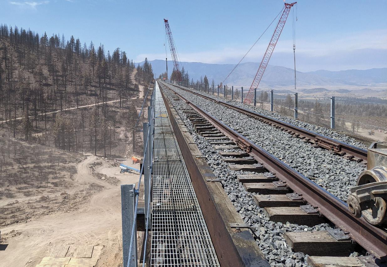
Heat straightening techniques may be applied to restore steel ele ments, whether a steel bridge suffers damage from wildfire, earthquake, vehicle impact, or overload. For the vital I-5 corridor connecting Roseville, California, to Portland, Oregon, UPRR could not afford to have the Dry Canyon bridge out of service for months. Large-scale heat straightening allowed the team to move quickly rather than spend months fabricating new members.
Heat straightening may not be able to restore a bridge fully, but it is an excellent tool to expedite the repair and is typically minimally disruptive to traffic.
■
Matthew Miller is a Project Manager in field services for Modjeski and Masters. He works in the firm’s southeast region, leading construction, engineering, and inspection efforts (mjmiller@modjeski.com).




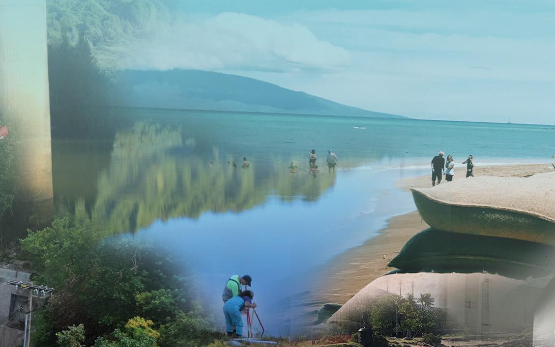














Figure 1. Building 12 existing condition.
Building 12 at Pier 70 in San Francisco has a long history that continues evolving. e building was originally constructed in 1941 and was used by Bethlehem Steel for shipbuilding in World War II. e building continued to be utilized for the construction of ships after the war and later was used to build the Bay Area Rapid Transit (BART) tunnels that cross under the San Francisco Bay. Unfortunately, in the recent past, the building has been essentially abandoned and fallen into disrepair until this project came to rescue it (Figure 1). e building is planned to be a retail/maker space in its future life. Shipbuilding designers and drafters were originally located on the upper floor. at floor will now house the designers and makers of wares, and their goods will be sold on the first-floor retail spaces. e renovation of building 12 is part of a more extensive ongoing redevelopment of the 65-acre pier and surrounding area, including rehabilitating 19 existing buildings and constructing 16 new buildings. is redevelopment will create an entirely new neighborhood in San Francisco and add a waterfront park.
Sea level rise was a concern for a project that significantly extended the lifespan of the building directly adjacent to the bay. e entire site was regraded and raised to combat this issue. To preserve Building 12, it was raised 10 feet to meet the new grade level. Another building on site will be a story shorter after its first floor is buried. Yet another building was moved to a new location.
Degenkolb Engineers was brought on by the general contractor, Plant Construction, to guide the project’s construction planning stage. At the time, Nabih Youssef Associates, SEoR for the building design, was mostly complete with the retrofit
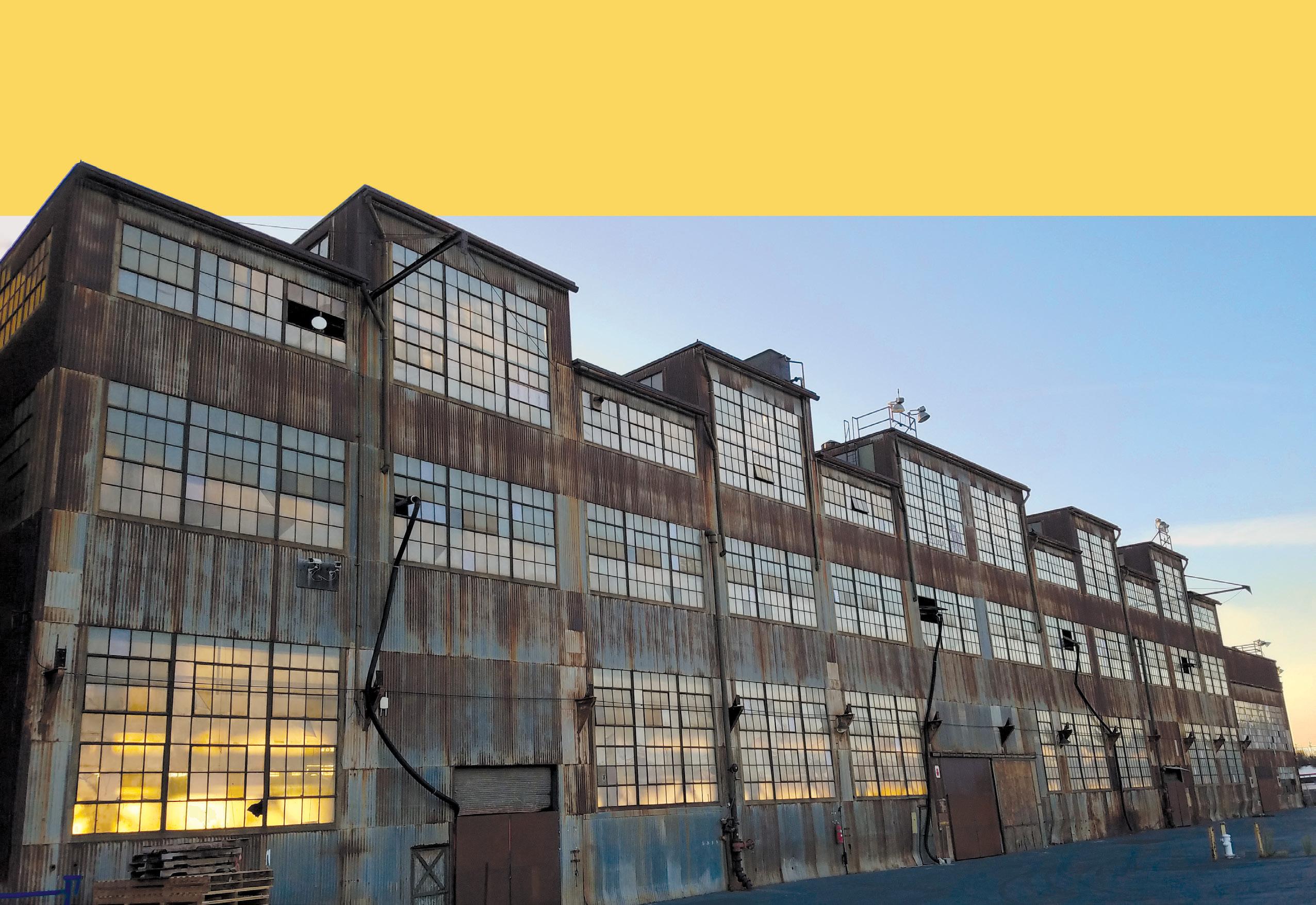
Figure
design of the existing building superstructure. It was understood that the building had to be lifted, but it was up to the contractor’s team to accomplish it.
Initial thoughts were that new foundations could be constructed offset several feet to the South and East of the existing foundations. e building would be lifted, shifted over, and then set down on the new foundation structure in one process. is would allow the new foundations to be built while the building rested on its original foundations. However, early discussion with lifting contractors determined that, while entirely possible, shifting the building’s location would add significant complexity to the solution. erefore, the team opted to leave the building in its current location and “just” elevate the building in place. is, in turn, meant that the building had to be held in place on shoring for several months while foundations and basement walls were built.
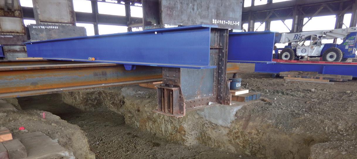
Since the building would be shored for an extended period, high wind loads were a significant consideration, and a small earthquake was even included as part of the design. Bigge Crane and Rigging was brought on as the lifting subcontractor and designer. Delineation of responsibility was drawn at the base of the existing building. Degenkolb would be responsible for the stability of the existing superstructure, and Bigge was responsible for the design and stability of the shoring system. Column vertical and lateral wind and seismic loads from Degenkolb’s analysis were coordinated with Bigge to design their systems.

Typical shoring systems only support vertical loads, and a separate lateral bracing system is needed. Bigge’s internal engineering team brought an innovative shoring system as part of their approach. eir jacks were incorporated into a 4-leg braced shoring system. Integrating jacks, shores, and bracing in one element meant that separate temporary lateral bracing would not be needed for the shoring. Other systems considered utilized temporary braced frames and other elements that needed to be installed once the lift was complete. is would leave the building vulnerable to lateral loads during the actual lifting and prove costly.
To lift a building is a massive undertaking, and this lift required the 66 columns’ differential movements to be kept within ½ inch throughout the lifting operation. erefore, hydraulic systems with an integrated computer-controlled monitoring and operations system were selected to keep the building within the tolerances.
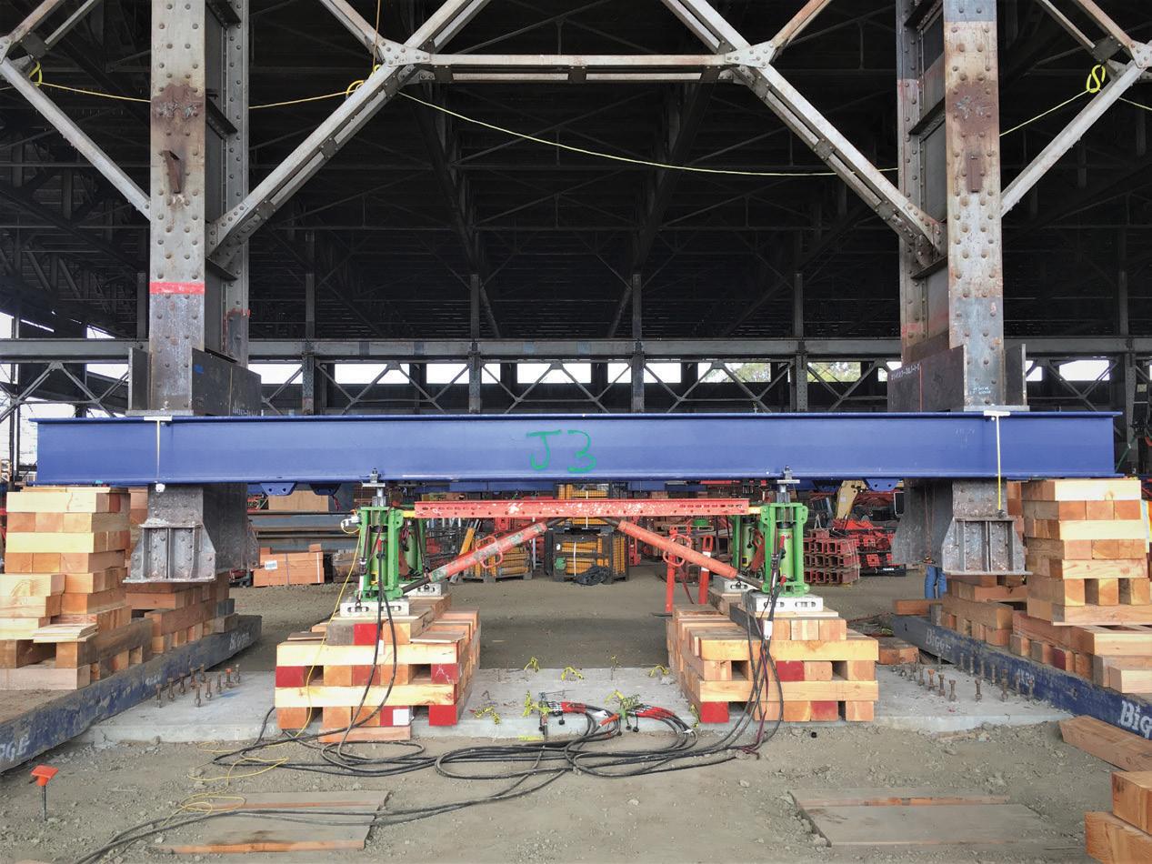
Temporary positive connections to the building columns were necessary for the lift. e architect limited connection to the building that would impact the historic patina of the columns as much as feasible. Ultimately, small areas of the columns were cleaned and prepped, and connection plates were welded to the columns to facilitate the lift. e team agreed that, while some irreversible marking was done to the building, these cleaned and ground portions of the column add to the story and history of the building and did not take from it.
Wind loads were not only a concern for the shoring system but also for the building itself. e building was originally designed as a moment frame with fixity at the foundations. Degenkolb analyzed the building in the lifted condition with the fixity removed and found the building would be significantly less stable. Over 5,000 feet of temporary 1-inch cable braces were added around the majority of the building perimeter to add stability back to the superstructure. Cable bracing wrapped around the building columns/beams eliminated the need to weld to the existing structure. is was important in preserving the existing condition of the building and limiting the need to remove lead-based paint from the structure.
e lifting was broken down into 3 major steps: Initial lift, Main Lift, and Set down.
e initial lift took the load off the existing building foundations and brought the building up approximately one-half inch. is allowed for the demolition of the existing building foundations and

placement of the new foundations and grade beams. It also kept the building relatively low to the ground, significantly reducing the shoring system’s overturning loads (Figure 2).
During the initial lift, several columns kicked out in plan as they were lifted off their anchor bolts. is was due to trapped loads from the original construction that were restrained by the anchor bolts up until the lift. ese movements were typically small and always less than 2 inches. Where they exceeded the one-half-inch
horizontal tolerance set out by the SEoR, the columns were winched back into place.
With the new foundations in place, the main lift could occur. First, the shoring/jacking system was installed under the shoring/jacking beams and pushed off the new foundations. The lifting operation proceeded in a rhythmic fashion: the jacks extended to raise the build ing just enough to install a new 5.5-inch layer of cribbing material at the ends of the jacking beams, then retracted the center jacks to set the building down to allow for the installation of another layer of cribbing under the center jacks (Figure 3, page 43 ).
This process continued until the wood cribbing stacks became tall enough to be replaced with new steel shoring ‘modules’ (Figure 4 ). Then, the process continued in a similar rhythmic fashion until the building was lifted to 11 feet above its original elevation. Throughout the process, immense manpower was needed to install wood cribbing, monitor control points, and install shoring modules at all 66 column locations.
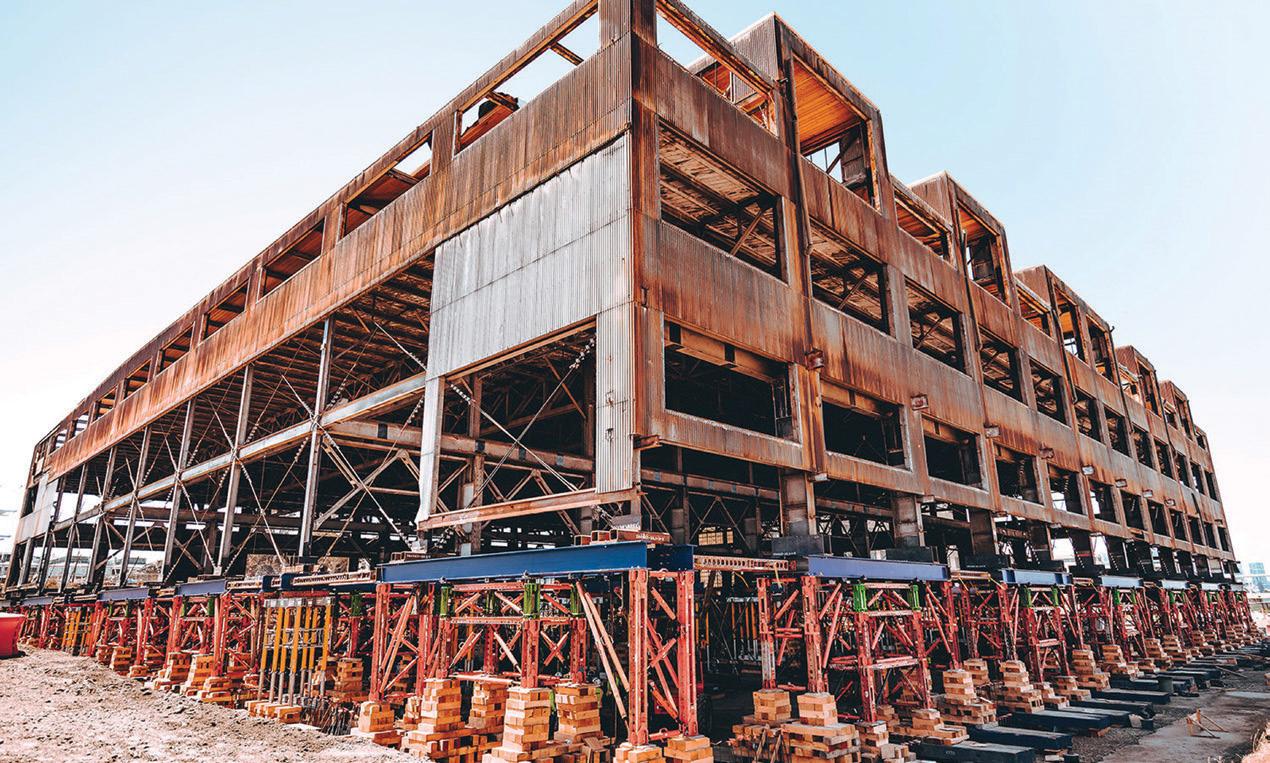
The lifting operation could not have been accomplished without a state-of-the-art computer-controlled hydraulic lifting system that relied on a single brain and three hydraulic hearts to ensure that all one hundred and thirty-six jacks were working in unison. Three Enerpac EVO-Series hydraulic electric pumps – the hearts – were connected to work in unison via one master computer controller – the brain.
Each EVO pump consisted of twelve independent hydraulic ports, each feeding the hydraulic fluid to the four jacks of a single jacking/ shoring-structure assembly.
Lifting cycles were executed automatically with a push of a button, and the lifting cycles were manually paused, when needed, to perform visual checks and cribbing additions/adjustments, etc., at jacking control points. During a lifting cycle, linear transducers (position sensors) at each jacking/shoring-structure assembly relayed realtime jack-extension measurements to the master controller. The controller used the jack-extension data and the measured hydraulic pressure data at each pump port to confirm that the proper amount of hydraulic fluid was distributed to each jacking control point. This process ensured that all one hundred and thirty-six jacks worked in sync. The master controller displayed the real-time jack-extension and jack-load data for each control point, which the system operator continually monitored.
With the main lift complete (Figure 5), the new steel building col umns could be installed below the existing columns. The columns’ splices were welded at the smaller wide flange columns and bolted up to the truss-supporting columns. The bolted connections preserved the original base plate connections so they could be exposed in the finished building. Because the lifting system is a costly rented item and hinders finishing construction, it was requested to determine if the shoring system could be removed once the column extensions were in place but without the first floor constructed. In this condition, the building columns would be two stories tall and only be braced in one direction by the cable bracing. The columns were checked and found to be adequate for the temporary condition (Figure 6 ).
Without the internally braced shoring modules, lateral wind loads were a significant concern. Therefore, a few negotiated basement walls were cast early to provide adequate temporary lateral resistance. In addition, the lifting beams remained to collect and deliver the lateral loads from the building above to the individual walls below. Once the new basement walls were cast and the new first-floor diaphragm was in place, the building was stable again, and the remaining shoring and bracing were removed.
As noted by the developer, it would have been less costly to demol ish the building and build new, but the site’s history would be lost. The authors were happy to be a part of the team, helping preserve the building and bring it new life.
■

Robert Graff is a Principal at Degenkolb Engineers and is active in their Construction Engineering group (rgraff@degenkolb.com).
Damian Gronsky and John Leventini are both with Bigge Crane & Rigging and may be reached at dgronsky@bigge.com and jleventini@bigge.com, respectively.











Reimagining the iconic Sixth Street Viaduct over the Los Angeles River began with an exhaustive design competition some 10 years ago. By the project’s end this summer, HNTB’s collaborative design approach will have unified and optimized the architecture of a new viaduct while creating a decidedly unique structure in both
e previous bridge was an emblematic piece of Los Angeles history, as it was the longest and most recognizable of the 12 bridges built over the river between 1923 and 1933. Since its opening in 1932, it has served as a backdrop for dozens of movies, TV shows, music videos, and video games. For these reasons, there was a strong desire to create a replacement structure that was equally impressive and beloved.
Dubbed the “Ribbon of Light,” the new viaduct continues that tradition in the language of our own time, with its efficient thin profiles made possible by a network of cables that support the bridge deck beneath. e design solution practically achieves the architecture of the viaduct by repetition, creating a striking and memorable bridge structure through the repeated use of concrete network tied arches flowing seamlessly into supporting Y-Bent substructures.
Marrying the architectural vision with the realities of structural engineering was a formidable task. Nevertheless, the Sixth Street Viaduct’s geometry and architectural goals literally dictated the project’s structural approach and led to several innovations.

is article examines the various engineering solutions devised in response to this unique design and the methodologies used to create a sustainable arch and pier system that provides unparalleled resistance to seismic events.
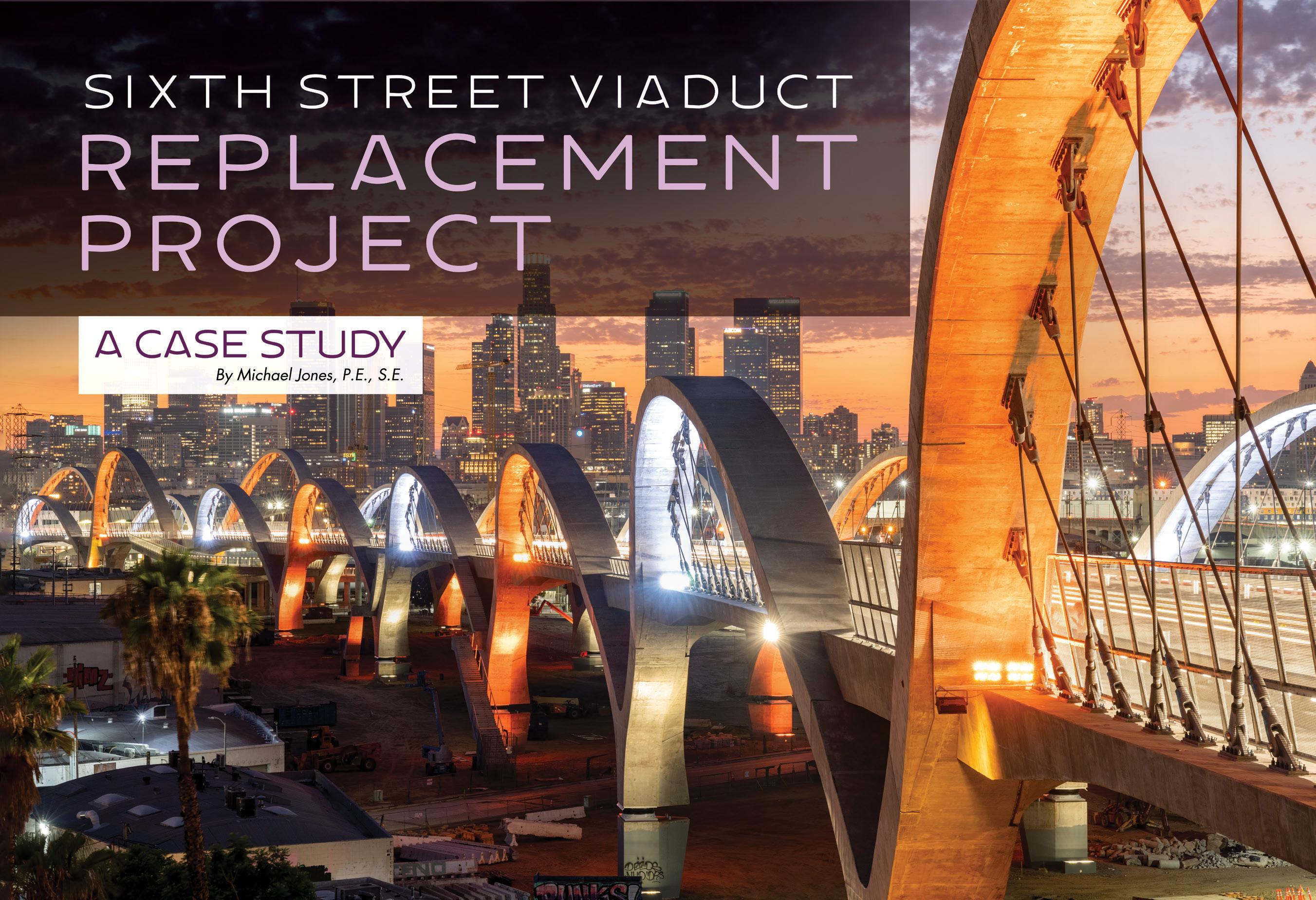
The ultimate fate of the Sixth Street Viaduct has with stood numerous iterations over the years. Initially, as part of the California Department of Transportation (Caltrans) state-wide effort to improve the seismic safety of the transportation system, plans were made to revamp the bridge after determining it to be seismi cally vulnerable.
The bridge’s condition, however, was decidedly worse than the other bridges being considered for retrofit –not from seismic vulnerabilities but from the presence of alkali-silica reactive aggregates used during its con struction. In layman’s terms, this “concrete cancer” had caused the concrete to deteriorate significantly during its lifespan, making it an impractical candidate for retrofit.
Ultimately, the Los Angeles Bureau of Engineering (BOE), under the leadership of City Engineer Gary Lee Moore, decided to replace the structure and, in 2012, launched an international design competition to ensure that the new bridge was as architecturally iconic as the original. That is when a small group of HNTB engineers and architects, along with representatives of Michael Maltzan Architecture in Los Angeles, convened for a preliminary discussion.
While other designers focused on matching the bridge with a similar signature structure limited to bridging the Los Angeles River, the team took a decid edly different approach. Their vision was to pursue a multi-purpose, multi-modal structure that could be integrated into the surrounding urban environ ment, extending the signature structure along the full 3,000-foot-plus length of the viaduct. Two potential concepts emerged: a concrete box bridge design clad with art-deco features to help it blend with other historic river crossings and a “stress ribbon” design to float lightly across the urban alignment. The team initially opted for the stress ribbon, given the design’s innate ability to serve as both a pedestrian bridge and bike path. However, it presented some daunting engineering challenges because it wasn’t practical for the profile grades and stiffness needed in a vehicular bridge.
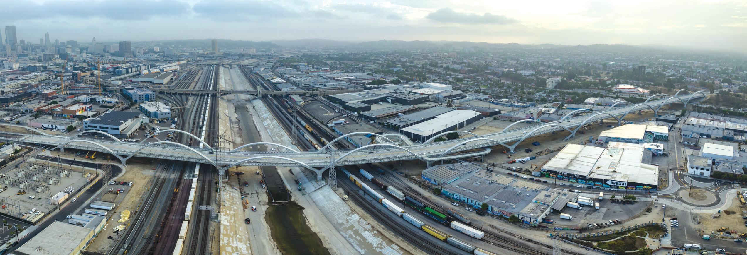
Later, a larger contingent of HNTB engineers and architects, Michael Maltzan Architecture, and Danish bridge architect Poul Ove Jensen of Dissing+Weitling updated the vision during a three-day workshop, moving away from the stress ribbon concept to a 10-span, concrete tied-arch bridge design. The team determined that the arch form could be more easily manipulated to achieve the desired architectural aesthetics while also giving a respectful nod to the original bridge’s two steel arch spans across the Los Angeles River.
Still, the design of the substructure remained undetermined. One thing was certain – the arch ribs would need to flow continuously down through the deck to the ground to integrate the bridge with the environment below.
Initially, architects favored an X-pier design, whereby each arch rib would continue through the deck. An adjoining arch rib would then continue on the other side, and the two would cross to create the “X.” But there were concerns about the seismic performance of the pier. While such a configuration is not uncommon in buildings where only lateral load is resisted by the X bracing, all of the vertical loadings of the bridge would need to pass through those members.
As an alternative, a Jensen-led team designed a second concept that incorporated a Y-pier substructure. With the Y-pier, the frame would come halfway down and meet at a vertical column configured as a moment-resistant system.
The HNTB design was well received by BOE and an advisory panel of architects, and a unanimous vote subsequently awarded the team the contract.
Upon contract award, the team continued pursuing the first option – 10 spans of continuous tied arches with X-piers. After more closely studying the concept, however, a reliable seismic system could not be devised, even after considering novel approaches such as a “rocking response” between the legs of the X-piers. While the concept has been considered during seismic retrofits, they determined it was not appropriate for a new structure.
Eventually, the team chose to move forward with the second concept. The Y-Bent design enabled the use of a conventional moment frame in the columns, a more traditional way for bridges to resist seismic forces.
A host of challenges remained, however. At a length exceeding 3,000 feet, the 10 continuous arch spans and nine continuous supporting Y-Bents needed to be interrupted by expansion joints to allow the

Rendering of X-pier substructure concept.
massive structure to expand and contract. The intermediate expan sion joints, although necessary, severely interrupted the sought-after aesthetic continuity of the structure.
Perhaps more concerning, computer models showed the arch ribs above the deck were not responding well, including significant dis placements when subjected to seismic ground displacements. This response was aggravated by the aesthetic goal of using unbraced and outward canted arch ribs. Caltrans had sponsored extensive research on the ductility of plastic hinges to dissipate seismic energy in bridge columns. Still, there was scant consensus that this research could be extrapolated to the unbraced and canted arch ribs.
These concerns led to considering seismic isolation, which proved to be a game-changer. However, due to the viaduct’s architecture, the isolators could not be placed on top of the substructure, typical in bridge practice since the arch ribs needed to flow continuously into the Y-pier. The bearings, after all, would have severed continuity between the arch ribs and the upper part of the pier.
The isolation bearings were placed within the vertical height of the Y-Bent columns. Placing the isolators within the vertical height of the supporting columns is unprecedented for a bridge and led to a funda mental change in the application of seismic isolation by the design team.
Historically, isolation bearings protect a structure from seismic damage and can vastly improve the structure’s functionality after a major seismic event. While the isolators are sized to meet anticipated seismic displacement demands, no provisions are required by guide specifications to protect the bearings themselves from seismic demands exceeding the anticipated earthquake. While potentially helpful, con servatively increasing the displacement capacity of the bearings is not a rational approach if the risks are not fully understood.
The approach chosen was to reconfigure the isolated system so that if seismic displacement demands on the bearings are ever exceeded, the bearing stiffens rapidly with a corresponding increase in lateral restraint. This required that the structure share attributes of a conven tionally designed non-isolated structure with ductile seismic hinges added that are only activated after a predetermined displacement within the isolator is exceeded. This “belt and suspender” system with a backup ductile system makes bearing failure and/or unseating within the column virtually impossible.
Next, various approaches were considered for the backup system. In finding the optimal location, the team first considered placing the ductile seismic hinge at the top of the Y-piers, situated at the bottom of the superstructure, to follow conventional construction.
However, in verifying ductility during a pushover analysis, high tor sion was observed in the arms of the piers. And once the hinge formed,
torsion continued to increase and therefore was not a case of equilibrium torsion. Since increasing torsion could not be tolerated in a ductile seismic hinge, the design team ultimately decided to place the contingency hinge within the 10-foot-diameter drilled shafts that support the structure. The circular section has excellent ductility due to good confinement details and low axial load ratios.
The project uses triple-pendulum isola tion bearings manufactured by Earthquake Protection Systems (EPS) in Vallejo, California. EPS invented the original single pendulum bearings in 1986, followed by the triple pendulum bearing in 2006. Over the years, these bearings have been supplied for bridges and buildings worldwide in highseismic areas.
This new isolation concept would essentially eliminate the possibility of bearing failure and substantially increase the reliability of their bear ings, regardless of the level of ground shaking assumed during design. After much prototype testing, the triple-pendulum bearings were modified to provide a dual radius on the outer slider of the triple-pen dulum bearing and modified the inner slider to transition between the two radii smoothly. As a result, the modified bearings manufactured for Sixth Street have the highest lateral strength to vertical load ratio (approximately 55%) ever manufactured by EPS. For comparison, at the 1,000-year-level seismic design event bearing displacements, lateral bearing forces transmitted to the substructure vary between 15% and 20% of the vertical load.
EPS also performed a FEMA P695, Quantification of Building Seismic Performance Factors, analysis against bearing failure and determined the reliability against collapse to be 99.99%, by far the highest of any of bearings furnished for past projects.
The Sixth Street Viaduct project was a hotbed of innovation. When the team determined that the Y-Bents would require strengthening to protect against hinging in the drilled shaft component of the secondary system, it suggested increasing the strength of the reinforcement from grade 60 to 80. This would provide an economical way to comply with the increased strength of the isolation bearings after stiffening
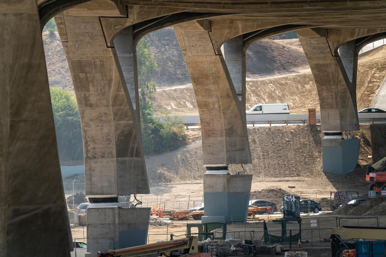

without requiring an increase in the reinforcement content of the Y-Bent or the component sizes.

Although Caltrans was in the process of evaluating the general use of grade 80 reinforcement in both ductile members and capacityprotected elements, research was still incomplete. Recognizing the requested use was for a secondary system that likely would not be activated, HNTB sought an exemption for the use of grade 80 rein forcement in capacity-protected members that would not be used for plastic hinging in the secondary system. Caltrans concurred and granted the request.
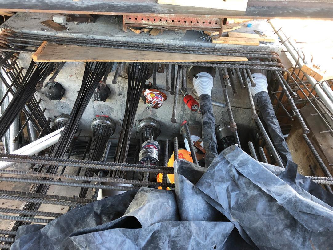

The use of seismic isolation provided another significant advantage. Since the isolation bearings severed the viaduct from ground con straint, all intermediate expansion joints could be removed, and the viaduct made continuous over its entire 3,060-foot length. However, due to practical construction sequencing limitations, including posttensioning stressing length limitations, the viaduct needed to be constructed in discrete frames with closure pours used to provide final connections between frames.
As a tied arch, each edge girder of the viaduct is particularly impor tant since the edge girders resist the axial thrust of the 10 continuous arches. The arms of the Y-Bents also require a tension restraint, with the thrust between opposing arms actually exceeding the arch thrust. The project’s prestressing systems specialist, DYWIDAG International, suggested using post-tensioned couplers to join the 10 4.5-inch-diameter edge girder tendons continu ing between sequencing frames. Although DYWIDAG could not reference a project where these couplers have been used in the U.S., they had previously developed, tested, and gained approval for their use on several European projects. After discussions with Caltrans, the team chose to use the couplers at each edge girder frame joint following verification testing.
With full continuity of the superstructure achieved, expansion joints were only required at each abutment. The team specified a low-maintenance seismic expansion plate joint still under development by Caltrans at the time. Intermediate expansion joints are always a maintenance concern, so limiting expansion joints to each end of the viaduct and using Caltrans’ developed low maintenance seismic steel plate type expansion joint minimizes the required long-term maintenance of the structure. Other project details were born from a need for sustain ability and structural longevity. For example, the team
specified post-tensioned floor beams in the transverse direction, resulting in post-tensioning of the structure in two directions. That, coupled with a low-shrinkage concrete mix for the superstructure, will ultimately reduce cracking and enhance the structure’s service life. The deck concrete also included a fiber-reinforced concrete mix.
Additional service life enhancements include hot-dipped galvaniz ing of all structural steel and bridge railings. Arch hangers are further protected with a zinc-aluminum alloy coating and a lubricating and blocking compound applied during stranding. All these measures reduce maintenance costs and increase the lifespan of the structure.
Once operational in the summer of 2022, the new Sixth Street Viaduct will be an aesthetically iconic structure in the heart of Los Angeles and a noteworthy and seismically sound addition to the city’s infrastructure landscape. There are high expectations that the replacement viaduct will represent the city for the next 100 years as a recognized icon and new backdrop for its bustling film and music industry.■
Michael Jones was HNTB’s Project Manager and Lead Bridge Engineer for the Sixth Street Viaduct Replacement. He is a member of the ASCE SEI Performance-Based Design for Structures Committee (mjones@hntb.com).

The David Rubenstein Forum at the University of Chicago is a new center for intellectual exchange, scholarly collaboration, and spe cial events. Designed by Diller Scofidio + Renfro (Architect of Record) and Brininstool + Lynch (Associate Architect), in collaboration with LERA Consulting Structural Engineers, the 97,000-square-foot struc ture consists of a 2-story podium and a 10-story tower of meeting room and social space neighborhoods, which are staggered to varying degrees. Conceived as a scholarly retreat from the hustle-and-bustle of downtown Chicago, the bold new conference center shifts the paradigm from traditional sprawling conference centers and hotel ballrooms. The Forum’s conference centers are stacked vertically and can accommodate gatherings from 75 to 600 people. Friedman Hall, a 285-seat auditorium, boldly cantilevers 40 feet to capture the pictur esque view over the tree-lined Midway Plaisance on the University’s iconic campus. The Forum has become a unique scholarly resource for the University and, despite opening during the COVID-19 Pandemic, has already hosted several notable events, including a talk by former President and University of Chicago professor Barack Obama.
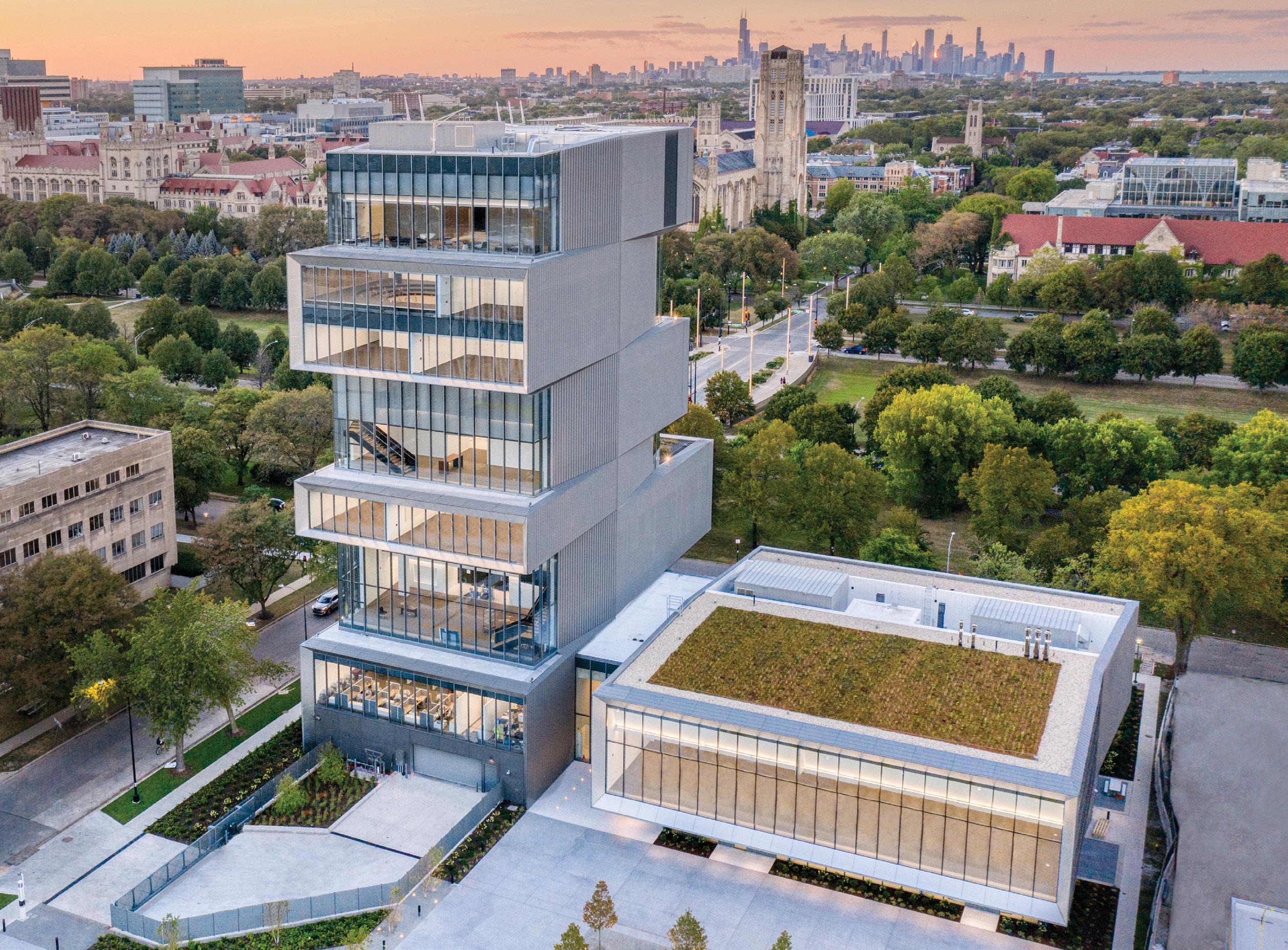
The structural system comprises a series of simple individual struc tural elements stacked in a harmonious form to efficiently create the desired open spaces, yielding column-free spans of up to 65 feet. Incorporating post-tensioned concrete into the structural design was crucial to achieving the design’s long spans, cantilevers, and columnfree spaces. At 166 feet tall, the Forum rises over 100 feet above the surrounding tree line, striking a dynamic form that symbolically ties together the history of Chicago’s Midway Plaisance, the University’s heritage and ambitions, and the architectural legacy of the area.
The staggered neighborhoods of the tower posed a complex engineer ing challenge that was ultimately solved with a unique structural system of stacked concrete boxes. Like how folding cardboard into a box allows it to be stronger than if it were flat, the Forum’s concrete structure is an efficient form for achieving the desired cantilevers and clear spans. None of the structural elements work particularly
At the podium, a pair of steel roof trusses rest upon and are transferred by a system of cantilevered post-tensioned slabs and beams at Level 2.

hard in isolation, but together, they work harmoniously to meet the project’s requirements.
LERA collaborated closely with DS+R through multiple massing schemes and design iterations. Several core design principles held true across the various schemes that informed the structural systems, which were key to helping meet the goals for the project. These included:
• Openness – to capture views of the University, the Chicago skyline, and Lake Michigan, as well as to allow for free stacking of the neighborhoods and flexibility of event planning without the need for expensive structural transfers.
• Simple Use of Familiar Materials – to enable the efficient construction of conventional structural elements and tech nologies commonly used in the Chicago concrete market.
• Unique Form – to “stitch” the north and south sides of Chicago together while simultaneously taking advantage of the prominent site location on the Midway Plaisance to create a highly visible landmark.
• Balance – to achieve the cantilevers to the north and south while minimizing the structural work required in the build ing’s “spine” and interior core.
Turner Construction Company, the project’s general contractor, and R. Olson Concrete Construction were involved early in the pre-construction planning through a design-assist role. With input from the post-tensioning supplier, the contracting team reviewed and priced the various design schemes while providing construction feedback to the design team. This process helped the team arrive at the as-constructed design, which met the project’s budget and wherein the innovation of the structure lies in its simplicity. In the tower, post-tensioned slabs and walls are stacked in an efficient form to create the desired open spaces, which proved economical because it allowed the contractor to build with the same materials and systems used on typical concrete projects in Chicago.
The main support for the tower is provided by a pair of 12-inchthick, conventionally reinforced concrete side walls that are skewed from neighborhood to neighborhood. These side walls, and the slabs connected to them, work together compositely to

form the stiff box-like structures that cantilever out to the north and south. The back-and-forth cantilevers are balanced to help minimize the amount of bending induced into the building’s spine and central core, which enables the use of thin 8-inch-thick shear walls around the elevators and egress stairs, where space is limited and coordina tion of systems is critical. In addition to designing the side walls for the cantilever spans, designing the walls for the out-of-plane moments due to the fixity of the slabs to the walls proved to be an essential design consideration. Four rectangular concrete columns

also support the slabs and are located just outside the central core to preserve the open concept. Unbonded post-tensioning is used in the floor slabs, which form the top and bottom of the stacked boxes, to enable the 65-foot spans between the side walls and reduce the tensile stresses in the top of the cantilevered boxes. ese long, column-free spans are an essential component of the functionality of the building, maintaining openness throughout. Dubbed sculpted slabs by the design team, the typical slabs are 10 inches thick and are only thickened (or sculpted ) where needed. For example, thickening occurs where the side walls are skewed and do not align from the floor above to the floor below, and at interior-to-exterior transitions to reduce deflections where the
façade attaches to the building structure. e result is a long-span slab that is efficiently constructed with simple, flat formwork and allows for an efficient distribution of ductwork due to the absence of interior beams.
e stacked neighborhoods were modeled in multi-story posttensioning analysis and design software to capture the composite behavior between the slabs and the cantilevered side walls in the post-tensioning design. is resulted in an average effective posttensioning force for a typical floor slab of about 35 kips/foot, which is a modest increase over normative post-tensioned slabs with shorter spans, demonstrating the system’s efficiency.
An important part of the design process was the coordination of expected slab movements with the façade contractor, Glass Solutions, Inc. Post-tensioning not only helped limit the deflections of the slab but because it precompresses the concrete to eliminate cracking, the anticipated deflection values could be reported to the façade contractor with precision and confidence. Expected deflections were reported to the contracting team at three stages: 1) e elevation of the slab at the time of façade installation; 2) the deflection of the slab due to the weight of the façade; and 3) the long-term deflection, including creep effects, after the façade was installed. is effort was crucial in coordinating the installation and alignment of important architectural finish details and ensuring the façade connections and joints were detailed for the movements.
e structural design took advantage of the high-strength concrete available in Chicago. All concrete used in the superstructure has a compressive strength of 8,000 psi or higher. In addition to using high-strength concrete, the modulus of elasticity and a low 28-day drying shrinkage limit were specified, along with additional rebar placed in the slabs along the walls. ese additional requirements served to minimize the likelihood of developing cracking in the slabs due to the restraint-to-shortening effects caused by the robust side walls.


As with the tower, the principle of openness remained key at the podium. Here, however, the clear span over the University Room – a large multipurpose space on the 2nd Floor accommodating up to 600 people – is 105 feet, as compared to the 65-foot clear spans in the tower. e design uses a pair of steel roof trusses, which in turn rest upon, and are transferred by, a system of cantilevered post-tensioned slabs and beams at Level 2 to accomplish this longer span.

To allow for a high ceiling at the interface with the façade, the trusses are set back from the south edge of the University Room, which also requires the steel roof beams to cantilever from the trusses.
Staged stressing of the Level 2 post-tensioned beams was neces sary. Therefore, 50% of the PT tendons were stressed after casting the Level 2 slab, and the remaining tendons were stressed after the University Room roof slab-on-metal-deck was cast.
A technical challenge with the structural design of the podium was understanding how the cantilevered post-tensioned slabs and beams at Level 2 impacted the movement of the steel framing at the roof. The façade was initially conceived to be hung from the tips of the cantilevered roof beams. However, the deflection curvature of the slabs at Level 2 and the roof are in opposite directions, which created a unique worst-case scenario on the project for the façade detailing, and would have resulted in a large joint where the floor meets the façade. To accommodate the large differential deflections and to help achieve the important finish details at the floor-to-façade interface without a joint, LERA recommended base loading the façade onto the Level 2 posttensioned slabs and beams and concealing the large movement joint in the ceiling where it would be out of view.
The design of the Rubenstein Forum was a significant challenge, but, ultimately, it was executed in a simple way that successfully achieved the aspirations of the University of Chicago and DS+R, and it has already become a beacon for the campus and surrounding community. Its striking architectural form was made possible by the stacked concrete boxes, an example of the true integration of architecture and structure.■
Michael Hopper is an Associate Partner with LERA in New York, NY. He serves on PTI’s DC-20 Building Design Committee and teaches the Design of Concrete Structures at Princeton University in Princeton, NJ (michael.hopper@lera.com).
Owner: University of Chicago, Chicago, IL
Structural Engineer-of-Record: LERA Consulting Structural Engineers, New York, NY

Design Architect/Architect of Record: Diller Scofidio + Renfro, New York, NY
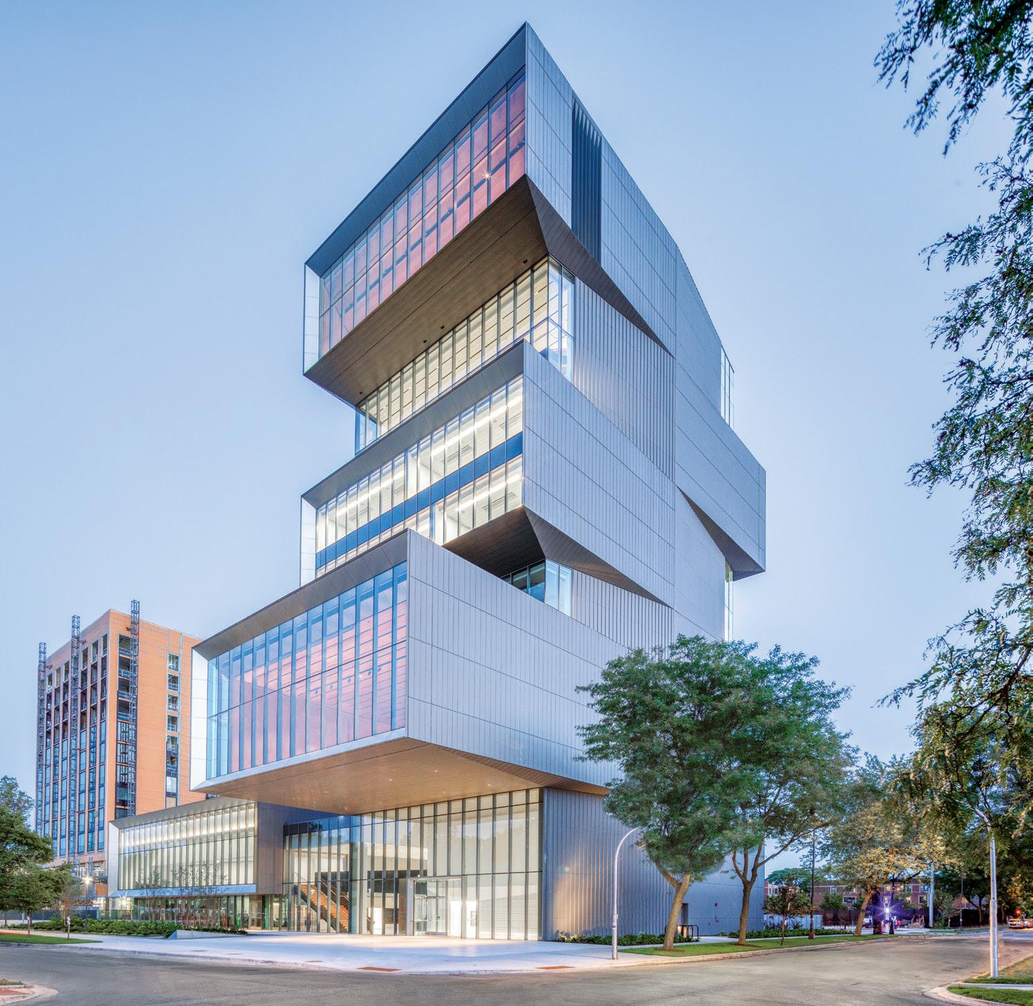
Associate Architect: Brininstool + Lynch, Chicago, IL
General Contractor: Turner Construction Company, Chicago, IL
Concrete Contractor: R. Olson Concrete Construction, Chicago, IL
PT Supplier: AMSYSCO, Romeoville, IL
Steel Contractor: Waukegan Steel, Waukegan, IL
Curtain Wall Contractor: Glass Solutions, Inc., Itasca, IL
Structural Software Used: ETABS, SAP, ADAPT Builder
A typical “sculpted” post-tensioned slab. These slabs strike a balance between using minimal material quantities and ease of forming while allowing for a more efficient distribution of ductwork from the core due to the absence of interior beams.

In October 2021, PCA released a groundbreaking initiative called the Roadmap to Carbon Neutrality

The concept is simple: to mobilize our industry to dramatically reduce CO2 emissions and to achieve carbon neutrality across the entire cement and concrete value chain.




It’s an audacious goal, and we’ll need to work together across the built environment from design, to manufacturing, delivery, and construction.
Learn how you can be an important part of shaping a more sustainable world.

shapedbyconcrete.com


Contact Nick Ferrari at nferrari@cement.org
 CEMENT.ORG

As early as 1842, some early promoters of the Transcontinental Railroad selected a route that would cross the Mississippi between Rock City, Illinois, and Davenport, Iowa. They chose this site based on a survey in 1837 by Lt. Robert E. Lee, as the river was narrow and separated by Rock Island, the home of a former army fort. This would require a bridge over each branch and an embankment across the island. In 1850, Congress passed an act granting public lands to railroad companies to encourage the country’s development.
Congress also passed an act, in August 1852, granting a right-ofway for rail and plank roads on public lands.
A Railroad Bridge Company was formed by the Illinois Legislature on January 17, 1853, to “build, maintain, and use a railroad bridge over the Mississippi River, or that portion within the jurisdiction of the state of Illinois at or near Rock Island in such a manner as shall not materially obstruct or interfere with the free navigation of said river.”
The Chicago & Rock Island railroad, originally the Chicago & LaSalle Railroad Company, chartered on February 27, 1847, was built connect ing Chicago and Rock Island on the Mississippi River between 1852 and February 22, 1854, making it the first railroad to reach the river.
At the same time, the Mississippi & Missouri Railroad, chartered on January 1, 1853, by the State of Iowa, was being built between Davenport and Council Bluffs and would reach Muscatine, Iowa, in late 1855. The Federal Government granted it about 1.25 million acres of public land to assist in its construction. However, it would not reach Council Bluffs, the point President Lincoln picked as the east terminus of the Union Pacific Railroad on the Missouri River, until May 11, 1869. At the time, it had been purchased by the Chicago, Rock Island, and Pacific Railroad.
The question arose of what type of bridge should be built and who should design and build it so that it did not interfere with the “free
route of Chicago & Rock Island Railroad.

navigation” of the river. The steamboat owners, of course, argued that any bridge would hinder navigation. A low-level bridge with three spans was chosen from the Illinois shore to the island, which was not the main shipping channel. This was followed by a curved track on an embankment and then turned over the main shipping channel at right angles to the flow. A low-level bridge with a swing span was deemed necessary to pass shipping.
At this time, the B & O Railroad was building its extension from Cumberland to the Ohio River and had adopted iron Fink Trusses for its bridge style. Other lines were using Whipple and Bollman iron trusses. Some lines, however, still used wooden trusses, typically Howe Trusses with wooden arches similar to those used by Theodore Burr, as they had a lower first cost.
An injunction was sought by the Secretary of War, Jefferson Davis, who wanted the transcontinental railroad in the south and the steam boat operators to stop construction, but it was denied. Construction began on July 13, 1853, with a cornerstone laying ceremony on September 1, 1854. On September 8, 1853, the Chicago & Rock Island Railroad purchased the charter of the Railroad Bridge Company.
The long single-track bridge over the shipping channel consisted of five 250-foot spans with two spans on the Illinois side and three spans on the Iowa side, flanking a 286-foot-span wooden swing bridge with a curved top chord. John Warner was selected to build the stone piers and abutments, and Stone, Boomer & Company of Davenport were selected to build the superstructure. Andros B. Stone (his brother, Amasa Stone, was the builder of the ill-fated iron Ashtabula Bridge) was the brother-in-law of William Howe, the patentee for wooden trusses with iron verticals. He had purchased the patent rights in the west and built many of this style of bridge.
The Swing (draw) span “rotated on a massive center pier with a top width of 32 feet and was supported by a turntable bearing arrangement with twenty wheels on a twenty-eight-foot diameter track” with approximately 150 feet of clearance on both sides when open. At the time, it was the longest swing span in the United States. Swing bridges had been built over some of the early canals, and Squire Whipple built two in Canada on
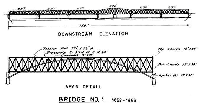
the Great Western Railroad in the early 1850s, but this was, by far, the longest. Octave Chanute would build one a little longer in Peoria, Illinois, across the Illinois River about the same time. e Rock Island Bridge’s draw was operated for the first time on April 9, 1856, and the first scheduled train passed over on April 22, 1856.


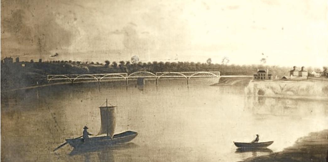
At the grand opening, Mayor James A. Grant, Davenport, opined, “All History proves the great path of the World’s Commerce to be from East to West; from India to Assyria and Egypt, from Egypt to Greece and Rome, from Rome to Spain and England, and from England to our own free America. It is certainly the duty of all wise men not to retard this Westward progress but rather to hasten it, bearing with it, as it does that blessed trinity, Commerce, Civilization, and Christianity; and that we regard all opposition to the workings of this great historic law as among the insanest of follies.” e celebration of the first railroad track to cross the Mississippi was short-lived as on May 6, 1856, only two weeks after its opening, the steamboat the Effie Afton, on a voyage from Cincinnati to St. Paul, ran into a pier and burned, setting one of the fixed spans on fire. Immediately the owner of the steamboat, Jacob Hurd, sued the bridge company, claiming the bridge was a hindrance to the free navigation of the river, and sought a settlement of $200,000. e Chicago Democratic Press described the collision as follows, “ e upper works of the boat struck against the bridge with so much violence as to knock all in pieces; smoke pipes, stoves, and the like were thrown down. e boat was set on fire in two or three places. e hull of the boat was, in the meantime, pressed under the bridge by the force of the current. e deck stood nearly at an angle of forty-five degrees. Boat and bridge were locked together. All was confusion – and yet several attempts were made to extinguish the fires. ese were supposed for a time to be successful, and yet, soon after, the flames broke out with such violence as to baffle all effort; but the connection with the bridge enabled the passengers to escape. ey got themselves and their baggage on shore. e flames, however, were soon communicated to the bridge. e outer end burned off and fell upon the burning steamer; the other end of that span was cut away, and bridge and steamer floated down together, a sheet of flame.”
e damaged span was rebuilt on falsework within four months, and the remaining spans were reinforced with chains running from the ends of the top chords down to the center of the span. e court case was well-publicized around the country and resulted in a hung jury. As a result, the bridge company, with Abraham Lincoln arguing for the bridge company, continued to use the bridge.
So the actual first railroad bridge across the Mississippi, as-built, only survived for two weeks. Still, its rebuilt and reinforced bridge carried traffic until 1866, when it was replaced by a heavier bridge that lasted until 1872. However, it had proved that heavy locomotives could cross the mighty Mississippi. It did not settle what the “right to free and unhindered navigation” was compared to the right of the railroads to cross the river on a bridge. at would be a discussion in Congress until 1866, when the first law was passed prescribing horizontal and vertical clearances for shipping on the Mississippi and Ohio Rivers.


The Bridges 2023 calendar features bridges from around the world celebrating the magical combination of technology and inspiration that is the hallmark of great engineering.


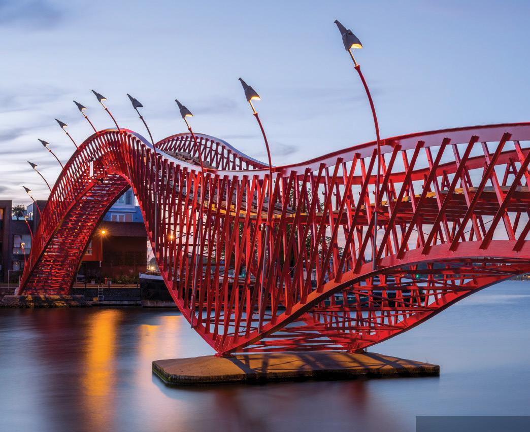




Little Island is an artificial island built on the Hudson River, providing a unique park experience for New Yorkers and tourists, including open space, nature, art, entertainment, and education. Its signature design distinguishes it from other piers with complex curved geometry, undulating and landscaped grade elevation, and irregular-looking pile grids. However, the design also imposed the most significant challenges for the structure and construction. Arup, the design team, quickly realized that the only solution to ensure that the geometry of construction would align on site would be a common design and construction model. erefore, the team adopted an open approach to 3-D modeling and digital information transfer and incorporated direct-to-manufacturing digital fabrication techniques.
Instead of a flat deck structure, Arup proposed pots made with architecturally exposed precast concrete directly supported by piles. ese pots are connected to create a single monolithic deck structure and receive the large volume of soil required for the vibrant landscape. To create the topography for landscaped hills, strolling paths, and overlooks, the deck and supporting pot structure vary in elevation, following the top surface contour rather than piling up soils and foams from a flat deck. e finished surface elevation of the pier varies from 15 to 65 feet above sea level.
Supported by 3-foot-diameter precast cylinder piles with HP14 extension (some as long as 260 feet), most of the deck structure consists of 132 unique pots. e typical pot is 15 feet tall and approximately 400 square feet on plan area. Each pot is composed of 4.5foot petals that sit on a central column head, seamlessly transitioning from the bulbous curved shape to the cylindrical pile geometry. e top of the extended core of the column head acts as a vertical support for planks and star beams above, which span radially from
the center to the pot corners.
e star beams are connected to those from neighboring pots using cast-in-place concrete fill. e center portion of the pier is predominately framed with more conventional rectilinear precast concrete bents and planks with cast-in-place topping. is configuration minimizes cost and leaves room for critical program areas such as back-of-house, undercroft, public restrooms, utility rooms, and performer changing rooms.
is flat pier area also supports the amphitheater with raker walls and stepped seating. e resulting structure is a highly indeterminate moment-frame structure, and for the seismic design, detail requirements of the intermediate moment frame were applied. In addition, much of the pot and petal structure is controlled by construction stresses during erection, so the design team needed to consider construction staging. e permanent design considers vertical loads due to self-weight, superimposed landscape and finish loads, pier live loads, theater live loads, and lateral loads from temperature, wind, seismic, ice, and wave loads.

Arup was an Outstanding Award Winner for the Little Island Project in the 2021 Annual NCSEA Excellence in Structural Engineering Awards Program in the Category – Other Structures.
A digital workflow was critical to the realization of the project on time and within budget. e architect generated the outside surface geometry of the pot through a parametric script after discussion with the structural engineer and fabricator. Internal surfaces were generated by Arup using added parametric algorithms to meet the required structural criteria and were geometrically simple to facilitate the conventional formwork fabrication. With all surfaces generated, Arup scripted the algorithms to generate detailed rebar models, light-gauge stay-in-place formworks, and stainless-steel connection plates, as it is impossible to
document all different unique geometries into conventional 2-D drawings. e precast fabricator realized the importance and future usage of the digital workflow and invested in equipment and staff training. As such, fully developed 3-D models were directly sent to the fabricator and then to a CNC machine to mill the foam formwork – the only solution for doubly curved concrete surfaces. From there, the models were sent to an automatic rebar bending machine and the process of laser cutting and bending steel plates. In this workflow, 2-D drawings were used only as a reference, and electronic file sharing and transfer were essential. Rapid tests of multiple logics in parametric modeling enabled the rationalization of the pot geometry such that only 39 sets of formworks would be needed to create 132 seemingly different pots. is saved significant time and cost.
Completed petals and column heads were assembled offsite into pots to facilitate and expedite the erection of pots on site. Fully assembled pots were transported by barge along the Hudson River and erected onto the pile by a large barge crane.
Little Island is a groundbreaking departure from conventional pier construction and utilizes the latest advances in digital design and fabrication technology to successfully deliver a structure that is both functional and playfully sculptural at the same time. It will be a new icon of the west side and a visible reminder of what can be achieved when the conventional scope boundaries of contractors and designers are blurred, and project participants come ready to collaborate.



Each year, NCSEA awards Young Member Scholarships for the NCSEA Structural Engineering Summit. We are pleased to announce the 15 winning young engineers. See their photos below. Their essay responses to the competition question – “What is your opinion about the public’s perception of structural engineers?” – are available at www.ncsea.com/awards



NCSEA also awards the Young Member Group of the Year at the Structural Engineering Summit. This award recognizes an outstanding Young Member Group (YMG) from one of the Structural Engineering Associations (SEAs). The emphasis of this award is to acknowledge Young Member Groups that are providing a benefit to their young members, SEAs, and communities. The winning Young Member Group will be announced at the Summit and receive an additional $2,500 for their Young Member Group to use for future activities.
This year’s finalists for the Young Member Group of the Year are:
Minnesota Structural Engineers Association


Structural Engineers Association – Metro Washington


Structural Engineers Association of New Mexico
Visit www.ncsea.com/awards to learn more about the scholarship program and Young Member Group of the Year award.
NCSEA thanks Computers & Structures, Inc. (CSI) for sponsoring this year’s young member scholarships and travel stipends for representatives from the Young Member Group finalists. Their investment in the future of the engineering profession is much appreciated!



Join Us at the NCSEA Structural Engineering Summit in Chicago, November 1-4.

The largest structural-engineering focused Exhibit Hall in the industry is your opportunity to connect with industry partners, engage with their products and services, and learn about the latest and greatest product innovations and software updates, all in an interactive and festive environment.
NCSEA would like to recognize and thank our exhibitors for supporting the NCSEA Structural Engineering Summit and serving as valued partners to the structural engineering community. Be sure to scan the QR code or visit ncseasummit.com/exhibit-hall for more information on all the exhibitors.
American Concrete Institute (ACI)

American Galvanizers Association

American Ground Screw, Inc.
American Institute of Steel Construction (AISC) American Society of Civil Engineers (ASCE)


Armatherm Thermal Bridging Solutions
Atlas Tube
Blind Bolt
BQE
Cast Connex Chicago Clamp
Concrete Fiber Solutions Concrete Reinforcing Steel Institute (CRSI)
CoreBrace
CSI
DACS
Dayton Superior DBM Vircon
DEWALT
Dlubal Software
Dymat Engineers Alliance for the Arts Epoxy Interest Group Euclid Chemical Fabreeka
FORSE Consulting Giza Steel Hilti
HYTORC
IDEA StatiCa Keller Lindapter
LNA Solutions MiTek
NCEES
*Exhibitor list as of 9/20/2022. Check the website for any updates.

New Millennium
Nucor
Peikko
Post-Tensioning Institute (PTI)
Prosoco PS=Ø Qnect

QuickFrames
Quick Tie Products
RISA
Seismic Bracing Company
Simpson Strong-Tie
SkyCiv
Steel Deck Institute (SDI) Steel Joist Institute (SJI) Steel Tube Institute (STI)
Taylor Devices
Trimble
Visit www.ncsea.com/education for the latest news on upcoming webinars and other virtual events.

October 18, 2022 Lessons Learned from North America's Largest Mass Timber Building
October 19-20, 2022
CalOES Safety Assessment Program October 2022: 2-Day Webinar
November 10, 2022 Pour Strips – Designing for Construction Productivity and Safety
Purchase an NCSEA webinar subscription and get access to all the educational content you’ll ever need! Subscribers receive access to a full year’s worth of live NCSEA education webinars (25+) and a recorded library of past webinars (170+) – all developed by leading experts; available whenever, wherever you need them!
Courses award 1.0-2.0 hours of Diamond Review-approved continuing education after the completion a quiz.

ASCE 7 Standard is now accepting new members for the 2028 edition of the standard. Applications being accepted until Dec. 18, 2022. Visit asce.org/asce7 for details.
SEI advances and serves the profession through its com mittees, producing standards, programs, publications, conferences, and continuing education. Get involved in an SEI volunteer effort in your area of expertise or inter est. It’s a great way to advance the profession and increase networking and learning. www.asce.org/SEICommittees
Student Members: Access National Academy of Construction Ask Me Anything webinars this Fall with a focus on Bridge Builders. Learn about careers in Bridge Design and Construction from experienced profession als. Students that submit a question before or during the webinar are entered to win a $500 scholarship. Learn more at www.naocon.org/nac-ask-me-anything.
Apply or Nominate by November 1
• Advance and be recognized as an SEI Fellow - Must be a current SEI member, actively involved in SEI, 10 years responsible charge (typically post P.E./S.E.) www.asce.org/SEIMembership

• O.H. Ammann Research Fellowship in Structural Design and Construction
• SEI and ASCE Structural Awards www.asce.org/SEIAwards
Birla Institute of Technology and Science Pilani, Rajasthan, India
The chapter aims to develop and promote current pro fessional and research practices in structural engi neering through workshops, conferences, and invited talks. As a link between academia and industry, the chapter offers pro fessional growth opportunities for current students by enhancing their connections with structural engineering professionals and researchers. www.bits-pilani.ac.in/university/SEIGSC/home
Learn more about SEI Chapters at www.asce.org/SEILocal
www.asce.org/SEI


Whether you are a member
Futures Fund
Investing in the Future of Our Profession
Learn the latest, connect with your peers, and envision the future with SEI in New Orleans on May 3-6, 2023. More than 50 scholarships are available, including a NEW opportunity for Students/Recent Grads to present and receive mentoring. Made possible by the SEI Futures Fund in collaboration with the ASCE Foundation. Learn more and apply at www.structurescongress.org/program/scholarships
Explore emerging technologies, how the Infrastructure Investment and Jobs Act (IIJA) impacts you, and prepare for a new era of equitable, resilient, and sustainable infrastructure development. ASCE Convention registration includes ASCE Tech Talks live webinars November 15-17.
ASCE Tech Talks Highlight:

Structural Safety, Engineering Ethics, &Aesthetics Presented by Rui Liu, Ph.D., P.E., M.ASCE and Sigrid Adriaenssens, Ph.D., F.SEI, A.M.ASCE Learn more and register at https://convention.asce.org/program/tech-talks-22.

personal and professional knowledge.
enhance
October 16-19, 2022, Colorado Springs, Colorado

ACEC sponsors two major national meetings each year: the Annual Convention and the Fall Conference. National meetings allow attendees to obtain information about issues that affect the industry through informative education, networking, and exhibits.
The Coalition of Structural Engineers (CASE) is hosting two education sessions at this year's Fall Conference.
Why is Legal Advice about Contracts like Twinkies and Cockroaches?
Presented by Karen Erger, Lockton Companies
Client Selection and Liability for Engineering in an ERA of Emerging Technology and Delivery Models
Presented by Paula Dixon, Holmes-Murphy
And don’t forget to join the CASE roundtable, hosted in conjunction with the Coalition of American Mechanical and Electrical Engineers, where we will address our trending topics in structural engineering communities. To see the full schedule and to register, visit www.acec.org/conferences/2022-fall-conference

November 1, 2022, Chicago, IL
Are you positioned to succeed in a highly competitive profession? You know how to design and understand the code, but do you understand the business implications of your daily activities? NCSEA and CASE have teamed up, in conjunction with the Annual NCSEA Structural Engineering Summit, to better equip the structural engineering leaders of today and tomorrow with tools they can use to excel at the business side of structural engineering.
Join us Tuesday, November 1, 2022, from 8:30 am to 4:30 pm. www.ncseasummit.com
How to Prevent Small Projects from Becoming Big Problems
Online October 31 through November 18, 2022
Smaller projects can be a core revenue driver for engineering firm project man agers and firm principals. But, smaller projects still have the potential to carry significant risks that can drag on resources, profitability, and client satisfaction. The good news is that you can ensure that even the smallest projects deliver maximum profits with the right set of skills in your toolbox.
Learn the skills, hacks, secrets, formulas, trouble-shooters, and problem-solvers that delight engineering firm executives and clients with small project progress and outcomes.
Jared Jamison, P.E, a consultant for PSMJ, will be presenting this live online program.
ACEC Coalition members receive a discount. Find more information at www.acec.org/conferences under Coalitions.
CASE has tools and practice guidelines to help firms deal with a wide variety of business scenarios that structural engineering firms face daily. So whether your firm needs to establish a new Quality Assurance Program, update its risk management program, keep track of the skills engineers are learning at each level of experience, or need a sample contract document – CASE has the tools you need!
What’s Shaking? A new publication from CASE about Seismic Design
CASE Guideline 962-J Business Practice Guidelines of Seismic Design for the Structural Engineer. The purpose of this document is to provide insights into structural engineering services in regions where there is a seismic hazard. This document shares key design considerations as well as business practice considerations. Numerous resources are available that provide a much more exhaustive and advanced technical presentation of essential considerations when designing for earthquakes. Someone new to designing for earthquakes should consider taking a course in structural dynamics and seismic engineering, whether from a university or some other provider such as ASCE or NCSEA.
Check out some of the popular CASE Toolkit Documents:
CASE Tool 1-1 – Create a Culture for Managing Risks and Preventing Claims. Initially designed for structural engineers with high claims-to-revenue ratios, this download is intended to inject a risk management culture into your firm. This is the first and most comprehensive tool offered on risk management in the engineering industry. It includes a video, a storyboard, and a role-playing guide to involve your staff in the risk management discussion. It also includes sample commitment statements for your firm to buy into the process. So if you want to send your firm personnel on the path to sound risk management habits, this is where you start.
CASE Tool 2-1 A Risk Evaluation Checklist. This tool provides one way for you to act in both a preventative and proactive way before starting a project in your office. The purpose is to evaluate risk by considering various factors and perspectives and determining whether the risk(s) of the pursuit is a worthwhile investment of firm resources.
CASE Tool 3-2 Staffing and Revenue Projection Tool. CASE Tool 3-2: Staffing and Revenue Projection Tool firm and project planning are crucial to reducing your firm’s risk and avoiding claims. One major facet of firm planning is predicting upcoming revenue and staffing demand to ensure that your firm has the resources to service upcoming booked and potential projects adequately.
You can purchase these and other Risk Management Tools at www.acec.org/bookstore.
Is there something missing for your business practice? CASE is committed to publishing the right tools for you. Have an idea? We would love to hear from you!
If you are a CASE member, this tool and all publications are free. NCSEA and SEI members receive a discount on publications. Use discount code – NCSEASEI2022 when you check out.
At the Coalitions Summer Meeting in August, the CASE Executive Committee approved the Coalitions Strategic Plan and worked on finalizing the correlating CASE-specific Strategic Plan. The Coalitions Strategic Plan analyzes current industry trends and challenges; defines the core purpose, values, and goals of the Coalitions; and aligns with the ACEC Strategic Plan to create a roadmap for growth.
What does that mean for you…One of the main goals of the Strategic Plan, for both Coalitions and CASE specifically, is to have an engaged and diverse membership participating in the Coalition. One of the best ways to engage in the Coalition is to join a committee.
Do you know someone in your firm looking for ways to expand and strengthen their business skillset, gain experience serving on a commit tee, sharpen their leadership skills, and travel to interesting places? Then, please consider having them apply for a position on the committee. Committee member commitments include a monthly virtual meeting, working on relevant documents a few hours a month, and traveling to the winter and summer coalition meetings!
To apply, your firm should:
• Be a current member of ACEC
• Be a member of the Coalition of American Structural Engineers (CASE); or be willing to join the Coalition
• Be able to attend the groups’ regular face-to-face meetings each year: August, February (hotel, travel partially reimbursable)
• Be available to engage with the committees via email and video/conference call
• Have some specific experience and/or expertise to contribute to the group



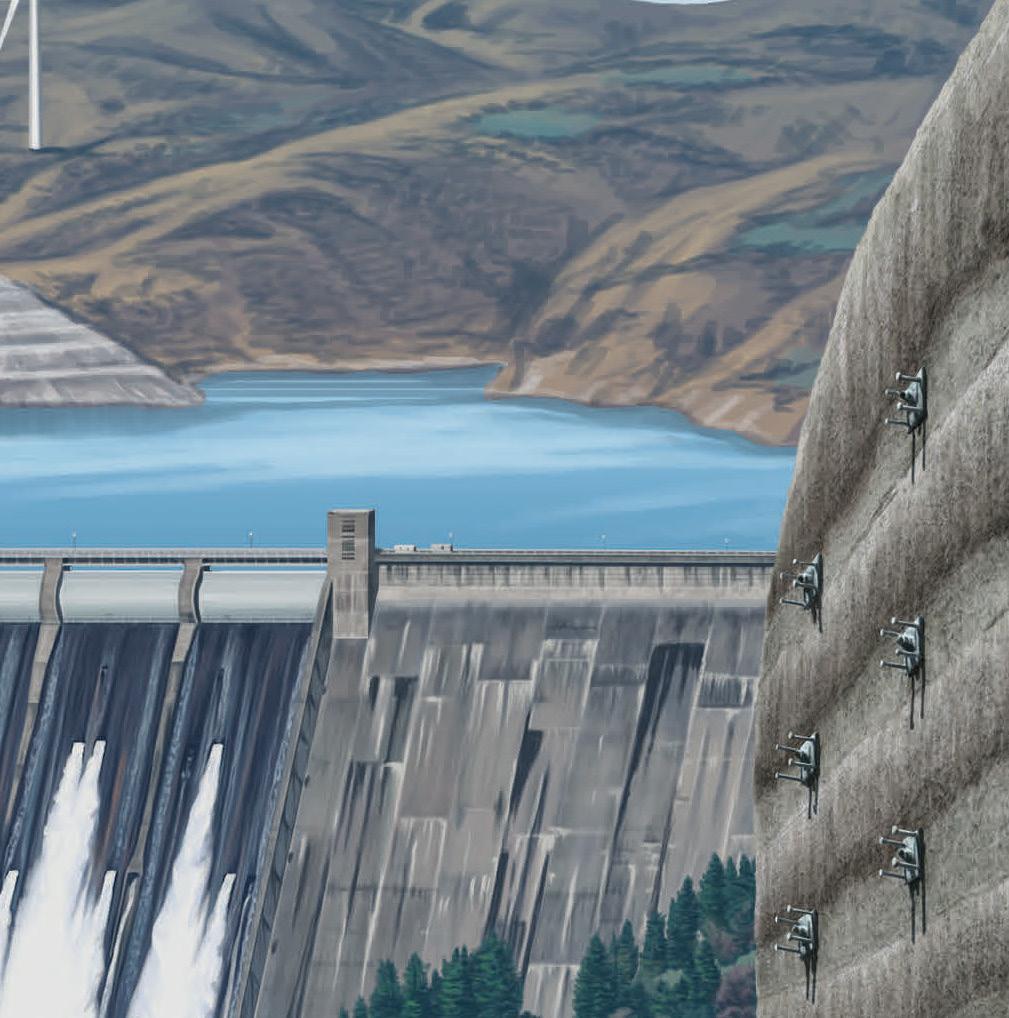


Phone: 754-399-1057
Email: atcinfo@atcepoxy.com
Web: www.atcepoxy.com
Product: ULTRABOND® Anchoring and Doweling Adhesives

Description: America’s #1 structural adhesive specialist offers four IBC compliant adhesives. HS-1CC, the world’s strongest anchoring epoxy. EPX-3CC high-performance epoxy for high-volume applications. HYB-2CC hybrid cures fast in hot and cold temperatures. ACRYL-8CC cures fast with a very broad application temperature range. ATC is a Meridian Adhesives Group Company.
Phone: 248-614-2400
Email: sframe-sales@altair.com
Web: www.altair.com/s-concrete
Product: S-CONCRETE
Description: A trusted industry standard, quickly and accurately designs reinforced concrete beams, columns, and walls. Reduce design time by automatically designing thousands of concrete elements simultaneously to produce a comprehensive engineering design report. Now with ACI 318-19 design code support for continuous concrete beams. Free trials available.

Phone: 407-284-9202
Email: support@asdipsoft.com Web: www.asdipsoft.com
Product: ASDIP STEEL
Description: Intuitive software for the design of steel members and connections, such as composite/ non-composite beams, steel columns, base plates, anchoring to concrete, shear connections, and moment connections, per the latest design codes.
ASDIP STEEL includes 5 modules that will substantially simplify time-consuming calculations for your structural designs.

Phone: 800-524-3244
Email: anchors@dewalt.com Web: http://anchors.dewalt.com/anchors
Product: CCU+ Critical Connection Undercut™ Description: DEWALT Anchors and Fasteners launches a new heavy-duty concrete anchor for use in critical applications where a robust anchor with low displacement is necessary. The CCU+ Critical Connection Undercut is ICC-ES qualified under ESR-4810 for use in cracked and uncracked concrete. The anchors are Made in the USA.
Phone: 800-424-2252 Email: info@enercalc.com Web: https://enercalc.com
Phone: 630-406-0600
Email: grippleinc@gripple.com
Web: www.gripple.com
Product: Terra-Lock
Description: Unique plate and anchor kit to secure a variety of TRM and HPTRM erosion control and slope stabilization matting. Proprietary design, easy to install, and open plate promotes vegetation regrowth.
Phone: 800-645-0616
Email: jenniferm@h-b.com Web: h-b.com
Product: Thermal 2-Seal™ Wing Nut Anchors
Description: An innovative single screw veneer tie for metal stud construction featuring a dual-diameter barrel with factory-installed EPDM washers to seal both the face of the insulation and the air/vapor barrier, and unique Thermal Wings that are designed to decrease thermal transfer through rigid insulation.

Phone: 800-707-0816 Email: info@iesweb.com Web: www.iesweb.com
Product: IES VAConnect
Description: Design base plates by AISC Design Guide #1 with ACI 318 anchorage calculations. Both tasks are difficult by hand! With VAConnect get your jobs done quickly and accurately. Use VAConnect as a stand-alone product or import design loads and column sizes from VisualAnalysis. Try it free.
Phone: 888-724-2323 Email: inquiries@lnasolutions.com Web: www.lnasolutions.com
Product: Box Bolt®
Description: A blind bolt fastener that is ICC ESR-3217 approved for seismic design. It connects tube steel or where access is restricted to one side of structural steel and is used with rectangular, square, or circular sections. Provides fast, easy installation.
Phone: 800-355-8414 Email: sales@pourstrip0.com Web: www.pourstrip0.com
Product: PS=Ø Mechanical Reinforcement Splice System
Description: Eliminates pour strips, wall restraint, and expansion joints. Allows volume change in the slab and provides structural integrity. Proven coupler technologies; the System features a thread on one end and a grout-filled sleeve on the other. ACI-permitted Type 1 and Type 2 mechanical splice, ICC-approved and made in the USA.
Phone: 800-925-5099
Email: web@strongtie.com
Web: www.strongtie.com
Product: Anchoring, Fastening, and Restoration Solutions Product Guide
Description: The comprehensive product guide features up-to-date products and technical information to locate the ideal product solution for your job. The Anchoring, Fastening, and Restoration Solutions Product Guide provides information on adhesives, mechanical anchors, direct fastening, carbide drill bills, and concrete restoration products for concrete and masonry.
Phone: 800-838-0899
Email: zoe.liang@skyciv.com Web: skyciv.com
Product: Reinforced Concrete Design Software
Description: Member Design for ACI 318, AS 3600, BS 8110, CSA A23, and EN 2. All with powerful, clean reporting.
Phone: 678-737-7379
Email: jodi.hendrixson@trimble.com Web: www.tekla.com/us

Product: Tekla Structural Designer
Description: With Tekla Structural Designer, engineers have the power to analyze and design multi-material buildings efficiently and cost effectively. Physical, information-rich models contain all the intelligence needed to fully automate design and document projects, including end force reactions communicated with two-way BIM integration, comprehensive reports, and drawings.
Phone: 203-523-5833
Email: julien@toggler.com Web: www.wejit.com
Product: POWER-Skru Large Diameter Concrete Screw
Description: A high-strength screw anchor with self-tapping threads that offers a unique undercutting design for anchoring into concrete and masonry. No secondary setting is needed. The POWER-Skru Large Diameter Concrete Screw provides high-strength performance with low installation torque. A heavyduty mechanically-galvanized finish is available to enhance corrosion resistance.

Phone: 616-866-0815
Email: williams@williamsform.com Web: www.williamsform.com
Product: Anchor Systems
ENERCAL C
Product: ENERCALC Structural Engineering Library Description: Library’s newest modules are Flitch Plated Wood Beam and Steel Base Plate by FEM. Both modules can help designers refine design loads on anchor rods, common bolts, and framing anchors. Our subscriptions now provide both installed and cloud use, plus ENERCALC 3D FEM and earth retention modules.
Phone: 949-951-5815 Email: candicec@risa.com Web: risa.com
Product: RISAConnection
Description: At the cutting edge of next-generation connection design software and features full 3-D visualization as well as expandable reports for every limit state. Includes integration with Hilti Profis for anchorage design, support for column cap plate moment connections, and updated HSS tube connection.
Description: Williams Form Engineering Corporation has been providing threaded steel bars and accessories for rock anchors, soil anchors, high capacity concrete anchors, micropiles, tie rods, tiebacks, strand anchors, hollow bar anchors, post tensioning systems, and concrete forming hardware systems in the construction industry for over 100 years.
Listings are provided as a courtesy, STRUCTURE is not responsible for errors.
RISA delivers a suite of integrated software design solutions and technical support services that allow structural engineers to innovate with confidence, secure in the safety and efficiency of their designs. The following case studies illustrate these core values.
Southeast Community College Academic Excellence Center
Building Client: Southeast Community College
Structural Engineer: Olsson, Lincoln, NE
Born out of the desire to create a cornerstone for the new academic quad, the new 52,000-square-foot Academic Excellence Center aims to promote interconnected learning while providing students and faculty with modern generalpurpose classrooms and state-of-the-art health science labs.
Olsson encountered various challenges due to the project’s archi tectural requirements. An almost completely exposed structure, multiple non-continuous, de-coupled diaphragms (as a result of atrium spaces that spanned multiple floors), and a scrim wall that included the specific use of only dimensionally “square” wide flange required engineers to rely heavily on structural analysis software.
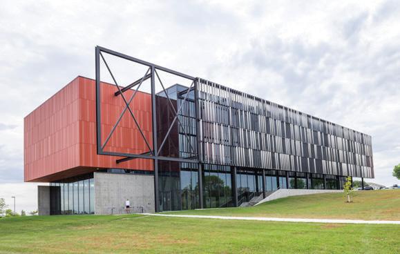
As a result, RISAFloor and RISA-3D were utilized to model the main three-story structure and design the composite floors and main lateral systems. Integration with RISAFoundation and RISAConnection were also utilized to design the building’s shallow concrete foundations and steel connections, respectively. Finally, the steel fins that make up the scrim wall were modeled separately in RISA-3D so that they could be independently analyzed for the anticipated wind load on the exterior of the structure.
Large types of equipment, such as a mobile stacker reclaimer, are crucial to handling and moving large amounts of bulk material in and around ports, power plants, and stockyards. Richmond Engineering Works designed, fabri cated, and assembled one such piece of equipment to be used at an export facility on Lake Erie, OH.
The equipment was designed to replace existing machinery and included specific requirements for digging capacity, traveling speed, amount of material handled (tons per hour), and boom reach. Due to the amount of equipment and unique geometry of the stacker reclaimer, structural steel was used to support the
loading conditions and the typical operating requirements. At the “front” of the system, the bucket wheel induces significant torsional moments into the boom requiring additional steel plate reinforcements. Additional challenges included designing a pair of 40-foot-deep tapered steel girders which cantilever out 50 feet at the rear.
To design this real-life “Transformer,” structural engineers at Richmond Engineering Works utilized RISA-3D’s advanced graphical capabilities paired with input data tables allowing for the creation of four separate models that were then appended into a single, comprehensive file. This allowed the engineers to work simultaneously to achieve the project design schedule. Additionally, a box section that formed the boom was analyzed as plates to fully grasp the stresses introduced into the structure by the bucket wheel.
Building Client: McDonald’s Corporation
Structural Engineer: CPH Engineers, Sanford, FL
McDonald’s first global net-zero restaurant, located in Kissimmee, FL, aims to provide the fast-food giant with a venue that will serve as a learning hub to test and develop sustainable solutions. The 8,000-square-foot renovation/remodel incorporates solar panels, living walls, natural shading, solar lighting, innovative heat reduc tion techniques, and unique structural steel framing to achieve a sustainable design that will create enough renewable energy on-site to cover the building’s energy needs on a net annual basis.
Structural steel was used on the project to provide endless design possibilities for the architect and engineer. The featured design element is an 18,000-square-foot butterfly roof with a 35-foot cantilever and support for over 1,000 solar panels. The roof’s shape also created incredibly high wind loads (as well as uplift forces) and, as a result, deep caisson foundations were utilized to help anchor the structure. Finally, the main CHS columns at the drive-thru (that support the tallest end of the roof) were filled with concrete to two-thirds of their height to control column slenderness. Due to the building’s challenging structural layout and loading conditions, engineers at CHP utilized RISA-3D to create a 3-D model of the entire steel structure including the roof structure which experienced heavy loads (due to wind uplift and the weight of the solar panels). The ability to precisely model the roof fram ing and the loading allowed engineers to visualize the deflected shape and ensure that the required maximum deflection (roughly 1 inch)
achieved.
Phone: 754-399-1057
Email: atcinfo@atcepoxy.com
Web: www.atcepoxy.com
Product: Pro Anchor Design Software
Description: This adhesive anchor-focused design tool aids in meeting the design strength requirements of ACI 318 for any of our IBC compliant products. Single pane interface. Rapid 3-D modeling. Realtime optimization of loading conditions, embedment depths, anchor sizes, and more. Accommodates threaded rod, rebar, and internal thread inserts. FREE download!
Adit Ltd
Phone: 00-972-77-5020696
Email: office@adit.org.il Web: www.adit.org.il
Product: Adit Anchor Software
Description: This is a user-friendly software to design post-installed anchors fit to the ENV 1992-4:2018 requirements or following the extended AAS method. It is a free software and available to download at https://files.adit.org.il/setup.exe
Phone: 203-421-4800
Email: sframe-sales@altair.com Web: s-frame.com
Product: Altair S-CONCRETE®
Description: The right concrete design solution is critical to reduce design time while ensuring code compliance. S-CONCRETE provides advanced design capabilities for reinforced concrete beams, columns, and walls for code compliance checks according to regional design codes. All design results are included in comprehensive, customizable engineering design reports.
Product: Altair S-FRAME
Description: Analyze and design with confidence using Altair S-FRAME. Perform advanced 3-D analysis of structures regardless of geometric complexity, material type, loading conditions, or nonlinear effects. Quickly design and produce code compliance reports with integrated concrete, steel, and foundation design. Advanced DXF and BIM data transfer links ensure optimum efficiency.
Phone: 407-284-9202
Email: support@asdipsoft.com Web: www.asdipsoft.com
Product: ASDIP SUITE
Description: For over 30 years, ASDIP has developed powerful yet simple-to-use tools to easily analyze, design, optimize, and check your structural members per the latest design codes. ASDIP software easily integrates with ETABS and other software to effortlessly optimize your structures with a few clicks.
Phone: 800-BENTLEY
Email: structuralinfo@bentley.com Web: www.bentley.com
Product: Structural WorkSuite
Description: Use what you want, when you want it, with our most comprehensive bundled structural software suite. Design in any infrastructure sector, with multiple materials, using any analysis method that is appropriate for the job. Reduce upfront costs, simplify business transactions, reuse data, and leverage the time saving power of interoperability.
Product: STAAD.Pro
Description: Perform comprehensive analysis and design for any size or type of structure faster than ever before with STAAD.Pro. Simplify your BIM workflow by using a physical model in STAAD.Pro that is automatically converted into the analytical model for your structural analysis. Share synchronized models for multi-discipline team collaboration.
Phone: 510-220-5310 Email: sales@csiamerica.com Web: www.csiamerica.com
Product: SAP2000, CSiBridge, ETABS, SAFE, PERFORM 3D
Description: CSI is recognized globally as the leading developer of software for structural and earthquake engineering. Backed by four decades of R&D, SAP2000, CSiBridge, ETABS, SAFE, and PERFORM-3D each offer unique capabilities that are tailored to different types of structures, allowing users to find just the right solution for their work.

Phone: 800-524-3244
Email: anchors@dewalt.com Web: http://anchors.dewalt.com
Product: DEWALT DESIGN ASSIST™ Description: State-of-the-art structural design software for concrete anchorages. Facilitates design efforts in base plate, equipment, and deck member anchorages, and post-installed rebar designs. Utilize an extensive library of mechanical, adhesive, and castin-place anchors with the Anchor Comparison Tool to easily see differences across anchor types, sizes, and brands. Download at website.
Phone: 800-424-2252
Email: info@enercalc.com Web: https://enercalc.com
Product: ENERCALC SEL/Structural Engineering Library/ENERCALC For Revit
Description: ENERCALC for Autodesk Revit simplifies structural design by bridging the gap between calculation and documentation. It allows engineers to access the familiar power of ENERCALC SEL as a seamless real-time extension of your Revit environment. ENERCALC’s use of the Revit API results in fast-paced, intuitive design with no import/ export process.
Hohmann & Barnard
Phone: 800-645-0616
Email: jenniferm@h-b.com Web: h-b.com
Product: ProWall Tools Featuring Thermal Brick Support
Description: Free software for architects, mason contractors, specifiers, and designers. Easily incorporate Thermal Brick Support (TBS) System design into projects, allowing brick support design that moves the shelf angle away from the wall, reducing thermal transfer. The TBS module in ProWall Tools allows a fast analysis of a brick support design.
IDEA StatiCa
Phone: 856-642-4070
Email: david.eckrote@ideastatica.com Web: www.ideastatica.com
Product: IDEA StatiCa
Description: Design any type of steel connection from scratch or import it from your analysis or detailing software. Apply simplified or complex loading. Visualize the connection behavior. Generate connection sketches and bill of material in seconds. IDEA StatiCa gets your connection design done for every configuration of steel connections you need.

Phone: 800-707-0816
Email: info@iesweb.com Web: www.iesweb.com
Product: IES ShapeBuilder

Description: The fastest way to find section properties for any cross section. Calculates shear and torsion properties as well as stress distribution. Reasonable pricing and licensing options. Try ShapeBuilder free today; it is a 2-minute download and setup.
Product: IES Total Suite
Description: IES offers over a dozen tools for analysis and design. Pick and choose the ones that add value to your practice, or get the entire suite at a great discount. From frames to foundations, IES products are field-proven by thousands of engineers for over 28 years.
INTEGRITY SOFTWARE, INC.
Phone: 512-372-8991 Email: sales@softwaremetering.com Web: www.softwaremetering.com
Product: SOFTRACK
Description: Use SofTrack to control Bentley Application usage by product code and feature (pipes, ponds, rails). Also control Bentley Passport/Visa usage. Receive idle usage alerts. Seamless operation for local and remote usage including Citrix sessions. Additionally benefit from Automatic Autodesk named-user tracking and reporting.
Listings are provided as a courtesy, STRUCTURE is not responsible for errors.
Computers and Structures, Inc. develops software for struc tural and earthquake engineering. CSI’s software is backed by more than four decades of research and development, making it the trusted choice of sophisticated design professionals every where. CSI is based in Walnut Creek, California, with offices in New York, Houston, Madrid, New Delhi, and the Caribbean.
Through the 1960s and into the 1970s, the University of California at Berkeley campus attracted some of the most bril liant minds in structural engineering. With the space program in full swing and nuclear power plants cropping up all over the country, it was not surprising that UC Berkeley became a hotbed of innovation that resulted in some of the most state-of-the-art computer solutions for complex engineering problems.
In 1970, following the development of a series of many unique and innovative numerical methods and algorithms, Dr. Edward L. Wilson, a distinguished professor of structural engineering at UC Berkeley, released the first comprehensive structural analysis computer program – called “SAP: A General Structural Analysis Program.” A revolutionary product that was destined to change the trajectory of engineering analysis forever!
Despite the availability of this sophisticated technology, it was not widely used by structural engineers initially. Users were mostly limited to government organizations and large compa nies. It took a young Berkeley structural engineering graduate, Ashraf Habibullah, to realize that someone needed to deliver the technology to the field.
“All this research was being done on campus, but none of it was reaching the profession. So there was a gap between what the researchers were producing and what the professionals could productively use in practice. I knew I could bridge this gap,” said Ashraf.
Habibullah approached Wilson and, with his help, created a comprehensive course at UC Berkeley Extension on computeraided structural analysis and design geared toward the practicing structural engineer, with a strong focus on earthquake engineering. The 12-lecture series generated an overwhelming response from the profession. Indeed, there was so much interest that the class had to be moved to a larger venue to accommodate the surge of registrants. Soon after, with growing interest in the technology, Habibullah and Wilson made presentations to packed audiences across the country.
In 1975, Habibullah founded Computers & Structures, Inc. (CSI) and positioned the company as a technology transfer link between researchers and professionals, producing practical prod ucts based on Dr. Wilson’s original research and work.
The advent of personal computers in the late 1970s allowed smaller companies and individuals to access CSI’s powerful
technology. This fueled the proliferation of the software world wide, especially in developing nations. In 1979, Habibullah and Wilson produced the first 3-D structural analysis modeling appli cation for personal computers. Its powerful numerical methods for earthquake engineering, integrated with new graphics and animation, permanently changed the course of the structural engineering profession.
Over the years, CSI has pioneered many developments in algo rithms for structural engineering and Finite Element Analysis technology that have addressed challenges that engineers have struggled with for decades. Using the latest and most advanced technology, CSI develops powerful software that directly addresses the needs of the structural engineering community. CSI products are the preferred teaching and research tools in thousands of universities and research organizations, including UC Berkeley, Stanford, Princeton, and MIT. In addition, CSI provides free software to academic institutions in many countries – includ ing Indonesia, Peru, Turkey, and Pakistan – to aid developing countries, specifically in earthquake-prone regions, in producing seismically-resistant structures.
Thousands of engineering firms use software from CSI in over 160 countries to design significant projects, including the Taipei 101 Tower in Taiwan, One World Trade Center in New York, the 2008 Olympics Birds Nest Stadium in Beijing, and the cablestayed Centenario Bridge over the Panama Canal.
CSI produces five primary software packages: SAP2000, CSiBridge, ETABS, SAFE, and PERFORM-3D.
Powerful, Easy-To-Use Structural Engineering Calculation Tools
To gain perspective on the uses of ENERCALC’s structural engineer ing software, consider your last flight. Before landing, a downtown cluster of skyscrapers, stadiums, and malls appeared. Surrounding them for many square miles are low-rise parking garages, manu facturing facilities, warehouses, retail, hotels, medical complexes, commercial buildings, and other structures that are 90% of structural engineering work.

For 40 years, ENERCALC has been committed to supplying structural engineering calculation software for this 90% while retaining simple entry forms with fast recalculation – just like our original spreadsheets.

Today, building codes are complex, with so many load combina tions and specific design details that hand calculations are no longer feasible. In addition to the classic structural calculation modules we offered, ENERCALC SEL now includes ENERCALC 3D FEM (a mature, easy-to-use 3-D FEM product formerly available only in our cloud software) and our earth-retention structure modules from RetainPro. All this in one easy-to-use user interface. These 3 products serve this 90% role completely and are available with budget-friendly subscription pricing.
In a “My office is where I am’’ world, ENERCALC is everywhere. With a simple, one-price subscription, you can:
• Install the software on any computer in any location: ENERCALC automatically manages allowed seat usage.
• Launch ENERCALC Cloud and access the same software globally through a browser. It is the same powerful Windows software – not a trivial subset of our desktop software deployed on the web.
• Safely and easily share project files between installed and cloud users, thanks to AWS’s secure, redundant global storage network.
• Access these applications via your browser from anywhere. Our global network of AWS data centers ensures a great, web-based experience, no matter where your work takes you.
ENERCALC for Revit simplifies structural design by closing the loop between documentation and calculation. It allows engineers to access the familiar power of ENERCALC SEL as a seamless real-time extension of your Revit environment. ENERCALC’s use of the Revit API results in fast-paced, intuitive design with no import/export process.
Using ENERCALC for Revit, you can instantly build a com plete ENERCALC calculation directly from Revit by simply clicking the element. Create and manage the same detailed structural design calculations you’ve come to rely on but in a fraction of the time. Then automatically update the Revit model from the results of your ENERCALC calculations!!
Design information automatically pulled from the Revit model –NO NEED FOR TEDIOUS VISUAL INSPECTION, MANUAL MEASUREMENTS, OR COPY /PASTE TO BUILD CALCS.
Calculations are built from physical Revit elements –NO NEED TO MANAGE OR MAINTAIN THE REVIT ANALYTICAL MODEL!
Calculations launch automatically in the ENERCALC SEL interface – NO IMPORT/EXPORT PROCESS!
Revit model updates instantly – NO REPETITIVE MODELING WORK AFTER COMPLETING CALCULATIONS!
After 40 years, ENERCALC remains a small, close-knit team focused on simplifying the work of structural and civil engineers.
Concrete Masonry Association of CA & NV
Phone: 916-722-1700
Email: info@cmacn.org
Web: www.cmacn.org
Product: CMD18
Description: Structural design of reinforced concrete and clay hollow unit masonry elements for design of masonry elements in accordance with provisions of Ch. 21 of 2010 through 2019 CBC or 2009 through 2018 IBC and 2008 through 2016 Building Code Requirements for Masonry Structures (TMS 402).
Hohmann & Barnard
Phone: 800-645-0616
Email: jenniferm@h-b.com Web: h-b.com
Product: TBS - Thermal Brick Support System
Description: A brick veneer support system that reduces thermal bridging in relief angles, to improve the energy efficiency of your building! Allows for continuous insulation behind the support angle, saving installation time and improving energy efficiency. Designed and engineered in-house to meet your specific project needs.
Phone: 800-633-6668
Email: jlarsen@larsenproducts.com
Web: www.larsenproducts.com
Product: Weld-Crete®
Description: A chemical concrete bonding agent incorporates polyvinyl acetate homopolymer in a patented formulation. For exterior and interior use, Weld-Crete will bond new concrete, Portland cement plaster, and cementitious mixes to structurally sound concrete floors, walls, columns, beams, steps and ramps.
Phone: 949-951-5815
Email: candicec@risa.com
Web: risa.com
Product: RISA-3D
Description: Harness the power of finite element analysis for your masonry design. RISA-3D allows you to draw and load masonry walls, openings, and lintels. Code checks for both in and out of plane are provided, as well as rebar optimization. Design includes the TMS 402-16 masonry code, both ASD and Strength.

Phone: 800-999-5099
Email: web@strongtie.com
Web: www.strongtie.com
Product: Fabric-Reinforced Cementitious Matrix (FRCM)
Description: FRCM combines a high-performance sprayable mortar with a carbon-fiber grid to create a thin structural layer that doesn’t add significant weight or volume to an existing structure. FRCM can be used to repair and strengthen concrete and masonry structures for seismic retrofit or load upgrades. Contact us for design support.
Phone: 303-939-9700
Email: info@masonrysociety.org Web: masonrysociety.org
Product: Webinars and Publications

Description: The Masonry Society is a not-forprofit, professional organization, dedicated to the advancement of masonry knowledge. The Society develops standards, guides, seminars, webinars, and other design resources.
Looking to Practice in Multiple States?
The National Council of Examiners for Engineering and Surveying (NCEES) is a nonprofit organization dedicated to advancing professional licensure for engineers and surveyors. Many professional engineers find that their careers require being licensed in more than one state. To do this, a P.E. must apply for comity licensure in additional states.
The NCEES Records program is designed for currently licensed engineers and surveyors who are looking for an easier and faster way to complete the licensure process in multiple jurisdictions, including all 50 states, the District of Columbia, Guam, Puerto Rico, Northern Mariana Islands, and the U.S. Virgin Islands. An established NCEES Record includes most – if not all – of the materials you need to apply for comity licensure in additional states and territories. Eliminate having to resubmit your:
• College transcripts
• Exam results
• Employment verifications
• Professional references
If you are already licensed and want to apply for licensure in an addi tional U.S. state or territory, apply for an NCEES Record. NCEES will review your materials and electronically submit them directly to
the licensing board on your behalf after your Record is established. This saves time and sim plifies the application process when you need to practice in multiple states and territories.
Professional engineers and surveyors who are actively serving in the military, and their spouses, are eligible to transmit their NCEES Records at no charge when military orders require them to move to a new state. When transmitted to a state licensing board, it will include a military designation to prioritize the application. Please email military@ncees.org for more information.
Are you in the process of becoming licensed and want to establish an NCEES Record? If you have passed the FE and PE exam, then some states allow you to use the NCEES Record for initial licen sure. A limited number of boards offer the initial licensing process, so check your MyNCEES account to find out if this is a path for you. Discover if an NCEES Record is right for you by visiting www.ncees.org/records.


Collaborate seamlessly, save time, and reduce costly errors. Tailored for teams of 20 or more, ICC Digital Codes Premium Enterprise advances how your team interacts with codes. Each customized package allows seamless onboarding and powerful administrative reporting while providing users easy access to the codes and standards they need every day.
• Streamline code research. Easily collaborate on projects across teams; research, highlight, and save relevant code sections together.
• One platform for your digital code database. Get full access to ICC’s industry-leading building codes and standards, all in one place.


• Never miss a code update. Our digital code database updates automatically, ensuring your team always works with the most recent set of codes.
• Improve your team’s expertise. Empower your team to understand and apply codes more effectively with ICC Digital Codes Premium webinars and expert code interpretations.
ICC Digital Codes Premium Enterprise agreements enable organizations to search, share, collaborate and manage building codes all in one place. This can help to save valuable time, reduce costly errors, and improve a firm’s efficiency.
• Administrative Control and Reporting easily monitors the contents and features utilized and by whom. Enterprise Admins can manage user access, and view activity reports through the system.
• Easy access only requires the end users to register or sign in to Digital Codes to access the contents and features. Users will always be able to access their contents and features.
• Onboarding/Training included in Enterprise agreements is created with an ICC Sales Specialist and comes with specialized training for teams to maximize benefits.
• Customized Enterprise Pricing is tailored to each customer based on seat count and desired contents. Contact an ICC Sales Specialist today to get your custom quote.


ICC Digital Codes Premium enhances an enterprise’s code experience with interactive features and advanced tools. To schedule a demo or for more information, contact Phil Anthony at 516824-8394 or panthony@iccsafe.org. To start your free 14-day trial, visit codes.iccsafe.org
Digital

Phone: 754-399-1057
Email: atcinfo@atcepoxy.com Web: www.atcepoxy.com
Product: CRACKBOND® Overlays and Sealers
Description: The world’s most advanced epoxy polymer concrete formulation. EPOTHANE T3 is a low-modulus, epoxy urethane skid-resistant overlay.
V65 HI-MOD, V120 LOW-MOD, and V200 HIMOD: a suite of healer/sealers with varying viscosities and moduli to extend the life of decks and roadways.
ATC is a Meridian Adhesives Group Company.
ASDIP Structural Software
Phone: 407-284-9202
Email: support@asdipsoft.com Web: www.asdipsoft.com
Product: ASDIP RETAIN
Description: Advanced software for quick and efficient design of cantilever, restrained, counterfort, and sheet pile retaining walls. See immediate results with calculations and reports of load combinations per the latest IBC/ASCE 7 and AASHTO. Includes 4 intuitive modules to help you design and verify structural members in no time.
Phone: 888-681-8786
Email: info@castconnex.com
Web: www.castconnex.com
Product: Standardized and Custom Cast Steel Connectors
Description: The industry leader in the architectural and structural use of cast steel components in the design and construction of building and bridge structures. Our products include pre-engineered connectors that simplify the design and enhance the performance of structures. We also offer design-build services for custom cast steel nodes and components.
Product: Cast Steel Nodes
Description: The use of cast steel nodes in steel bridge structures can provide improved fatigue performance, enhanced structural resilience, and can reduce the total life-cycle cost of pedestrian, road, and rail bridges.
Phone: 510-649-2200
Email: sales@csiamerica.com

Web: www.csiamerica.com
Product: CSiBridge
Description: Offers a single user interface to perform modeling, analysis, design, scheduling, load rating, and reporting of bridge structures. The ease with which these tasks can be accomplished makes CSiBridge the most versatile and productive software program available on the market today.
Listings are provided as a courtesy, STRUCTURE is not responsible for errors.
Phone: 714-614-7392
Email: sgoodman@ctscement.com Web: www.ctscement.com
Product: Komponent®
Description: An ASTM C845-compliant shrinkagecompensating additive blended with local portland cement to make Type K concrete and grouts for transportation, tunnel, water/wastewater containment, industrial floor, and commercial building. In addition to thwarting curling and cracking caused by drying shrinkage, the additive reduces the number of control joints.
Dlubal Software, Inc.
Phone: 267-702-2815
Email: info-us@dlubal.com Web: www.dlubal.com
Product: RFEM
Description: Capable of linear, non-linear, static, and dynamic analysis, RFEM is complete with moving load generation (AASHTO library), influence lines, cable form-finding, parametric modeling, and multi-material design considerations. This FEA software is seamless in the design and analysis of pedestrian and highway cablestayed, suspension, arch, and beam bridge structures.
Phone: 800-424-2252 Email: info@enercalc.com Web: https://enercalc.com
Product: ENERCALC Structural Engineering Library

Description: Major ENERCALC improvements for 2022 include the addition of ENERCALC 3D FEM and RetainPro modules to installed ENERCALC software. New FEM-powered Steel Base Plate and Flitch Plated Wood Beam modules. No more handcalculated Z values! Coming soon – ENERCALC for Revit – use the familiar calculation power of ENERCALC within Revit.
Phone: 646-732-7774 Email: info@lusas.com Web: www.lusas.com
Product: LUSAS Bridge Description: Use to analyze, design, and assess all types of bridge structures and investigate soil/structure interaction effects. Recent releases have extended the engineer’s workflow from analysis into steel and RC frame design and improved prestress, concrete modeling, and vehicle and rail loading capabilities.

Phone: 260-969-3500
Email: gerald.arvay@newmill.com Web: www.newmill.com
Product: Bridge-Dek®
Description: A high-strength, galvanized bridge deck forming system for new construction and rehabilitation.
Strongwell Corp.
Phone: 276-645-8000
Email: info@strongwell.com Web: www.strongwell.com
Product: EXTREN®
Description: The registered trade name for a proprietary line of standard pultruded fiberglass structural shapes and plate produced by Strongwell. The EXTREN line consists of more than 100 different fiberglass shapes, each with a very specific, proprietary composite design. Strongwell is the largest fabricator of structures utilizing pultruded components.


Trimble
Phone: 678-737-7379 Email: jodi.hendrixson@trimble.com Web: www.tekla.com/us

Product: Tekla Structures
Description: First class structural software for steel, concrete, wood and composite bridge structures, and details. With Tekla Structures, increase productivity through higher automation of fabrication and 4-D product management. An extensive range of steel profiles including elliptical and tubular, and individual connection details with welds and bolts.
Williams Form Engineering Corp.

Phone: 616-866-0815 Email: williams@williamsform.com Web: www.williamsform.com
Product: Post-Tensioning Systems
Description: Williams Form Engineering Corporation has been providing threaded steel bars and accessories to the bridge construction industry for over 100 years. Williams’ pre-stressing/post tensioning 150 KSI All-Thread-Bars are high tensile steel bars available in seven diameters from 1 to 3 inches with guaranteed tensile strengths to 1027 kips.
Our monthly 2023 Resource Guide forms are now available
Champion Bridge Drain is a lightweight, corrosion-resistant, and customizable drainage solution for bridges. The system contains all the fittings, non-metallic accessories, and hangers necessary to construct a bridge drain for roadway bridges, freeway overpasses, and parking garages. Champion Bridge Drain is the best choice in highly corrosive drainage applications due to its versatile, high-strength design.
Here are 11 reasons why you can rely on Champion Bridge Drain for proper drainage on bridge projects:
1) Strength and Durability – Champion Bridge Drain is made using epoxy resin for ultimate strength, corrosion resistance, and flame retardancy. As a composite material, Champion Fiberglass Bridge Drain is incredibly strong based on its high glass-to-resin (70% vs. 30%) ratio. The higher glass content makes the bridge drain much stronger, stiffer, and impact resistant. Fiberglass is engineered to handle loads and condi tions found in corrosive environments, and its durability helps contribute to long-term project success. It provides an excellent drainage system for roads containing significant volumes of water, thereby creating a safe driving environ ment for motorists.
2) Corrosion Resistance – As a high-performance, versatile drainage system, Champion Bridge Drain is designed for environmentally unfriendly drainage, such as elevated road way surfaces and bridges. It is engineered to handle harsh conditions as the epoxy resins enable it to withstand strong contaminants like gas, oil, and road salt commonly carried in water.
3) Light Weight – Champion Bridge Drain weighs just one-fifth the weight of comparable-sized cast iron and PVC drain age systems. As a result, Champion Fiberglass Bridge Drain significantly reduces dead load on bridges while offering the lowest weight per square foot without compromising strength.
4) Lower Installations Costs – In addition to low material costs, Champion Bridge Drain also offers cost-efficient installation. The fiberglass components are much lighter than steel and easier to cut, drill, and assemble than PVC or steel bridge drains. The result is a significant reduction in labor costs.
5) Broad Temperature Range and UV-Stable – Champion Bridge Drain withstands temperatures between -60° and +250° F and performs well at low temperatures, which allows yearround installation. It is UV-stable so that it won’t degrade in constant sunlight.
6) Easier Field Handling – Champion Bridge Drain’s light weight encourages better portability in the field. It offers ease of cutting and an integral bell and spigot design that facilitates a simple, fast installation.
7) High-impact Resistance – In addition to being strong and impact resistant, Champion Bridge Drain is capable of retaining its original shape after impact.
8) Extended Support Spans – Champion Bridge Drain offers extended support spans compared to SCH 40 PVC bridge drain systems. This saves installation labor and material costs for the additional supports required for PVC drainage systems
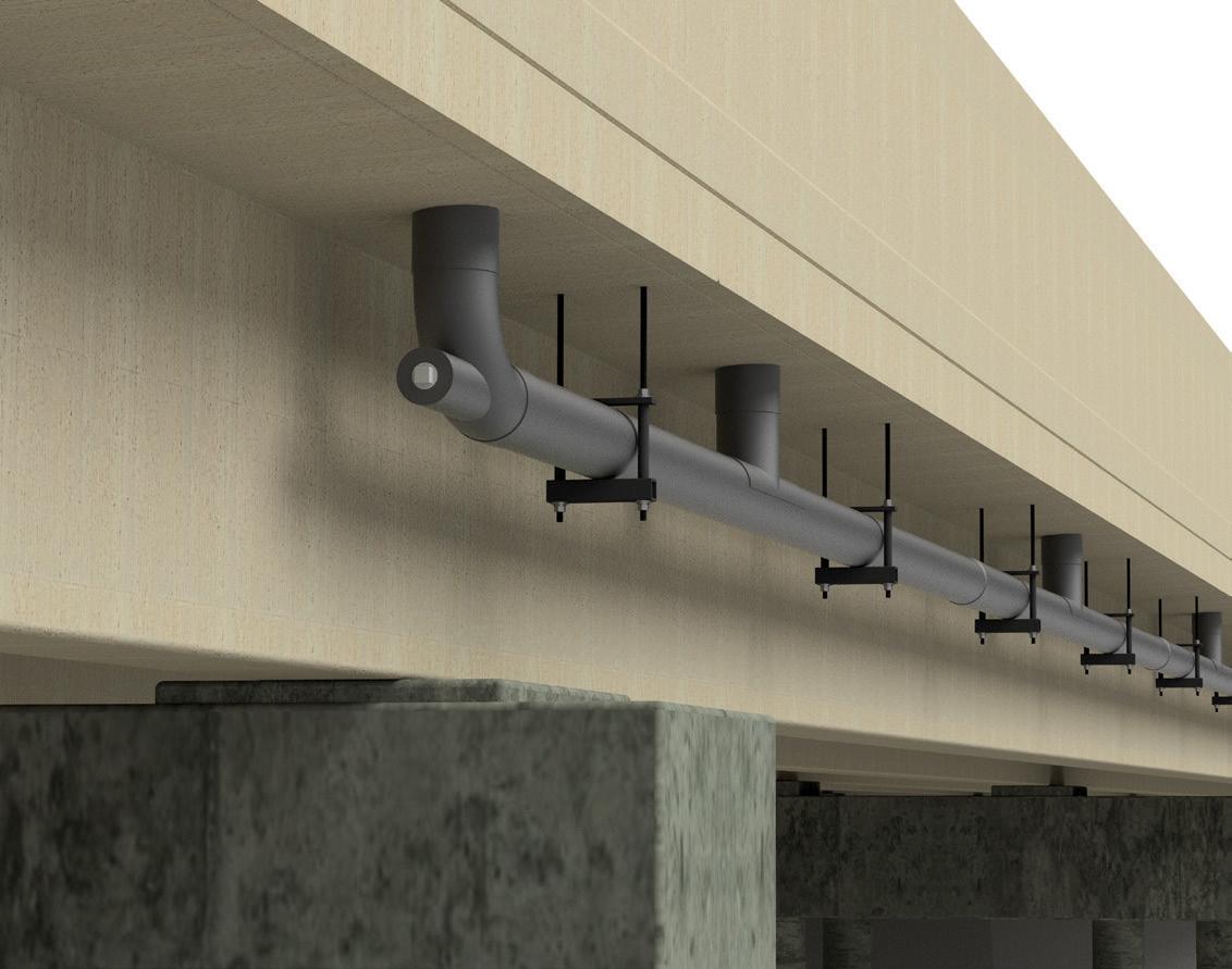
9) Customization – Besides providing a wide range of sizes, the Champion Fiberglass® team works closely with customers to develop custom solutions, whether it is a UV-resistant coat ing specific to the climate and sun exposure in your location or a customized color match.
10) Triple ISO-Certified Facility – Our Spring, Texas, facility strives to meet all industry standards and certifications, demonstrating our corporate commitment to environmen tal and system management requirements. In addition to being ISO 9001 and 14001 certified, Champion Fiberglass’ occupational health and safety management system has received the ISO 45001 certification for promoting a safe and healthy workplace.
11) Customer Support – Since 1988, Champion Fiberglass has been helping engineers, contractors, and project owners provide creative solutions to reach successful outcomes in industrial construction projects with its fiberglass conduit, strut, and bridge drain products. The Champion Fiberglass team enjoys assisting engineers and project owners as they build savings and success in their industries.
Phone: 407-284-9202
Email: support@asdipsoft.com Web: www.asdipsoft.com
Product: ASDIP STEEL
Description: Intuitive software for the design of steel members and connections, such as composite/ non-composite beams, steel columns, base plates, anchoring to concrete, shear connections, and moment connections, per the latest design codes.
ASDIP STEEL includes 5 modules that will substantially simplify time-consuming calculations for your structural designs.
Phone: 800-733-5683 Email: bradlee.fletcher@atlastube.com Web: www.atlastube.com
Product: Hollow Structural Sections
Description: Atlas Tube produces the largest hollow structural sections (HSS) in the world. Square and round shapes in sizes ranging from 8-inch square by 0.750-inch wall to 22-inch square by 1-inch wall. The largest rectangular sections produced are up to 30- by 14- by 1-inch wall.
Phone: 888-681-8786
Email: info@castconnex.com Web: www.castconnex.com
Product: Standardized and Custom Cast Steel Connectors
Description: The industry leader in the architectural and structural use of cast steel components in the design and construction of building and bridge structures. Our products include pre-engineered connectors that simplify the design and enhance the performance of structures. We also offer design-build services for custom cast steel nodes and components.
Phone: 800-424-2252 Email: info@enercalc.com Web: https://enercalc.com
Product: ENERCALC Structural Engineering Library/ ENERCALC for Revit
Description: ENERCALC for Revit simplifies structural design by bridging the gap between calculation and documentation. It allows engineers to access the familiar calculation power of ENERCALC SEL as a seamless real-time extension of your Revit environment. ENERCALC’s use of the Revit API results in fast-paced, intuitive design with no import/export/copy/paste.
Phone: 800-423-6587
Email: mtemesvary@icc-es.org Web: www.icc-es.org
Product: Product Certification
Description: ICC-ES is the leading evaluation service for innovative building materials, components, and systems. ICC-ES Evaluation Reports, Building Product Listings, and PMG Listings provide evidence that products and systems meet requirements of codes and technical standards worldwide, including the U.S., Canada, Mexico, Australia, New Zealand, and the MENA region.

IES, Inc.

Phone: 800-707-0816 Email: info@iesweb.com Web: www.iesweb.com
Product: IES VisualAnalysis
Description: Helps you design steel and cold-formed structures. Create models, apply loads, and get your frame or truss members optimized with AISC, AISI, or CISC design checks. Advanced direct analysis method. You stay in control at every step. Download your free trial today.

Steel Section continued on page SS-80
Chicago Clamp Company is a leading manufacturer of structural steel components that support rooftop equipment and loads suspended from steel joists and beams. The bolted systems from Chicago Clamp are the pre-engineered alternative to traditional welded angle methods. Our weld-free systems offer a simple, safe, and fast approach to providing all the structural support needed for roof accessories.
The Framing Clamp System is perfect for remodeling and retrofit projects looking to install new rooftop units and other roof accessories. There are two system versions: a light-duty frame that supports loads of up to 1,000 pounds and a heavy-duty ver sion that can transfer loads above that weight. Our systems are easily installed without any welding and within the corrugations of the building’s roof deck. Save time and reduce cost on your support framing projects for RTUs, exhaust fans, skylights, and all roof openings.
The Suspension Clamp System offers unmatched flexibility in suspension hardware. Equipment can be suspended from joists at the necessary locations using 5⁄ 8-inch bolts or threaded rods. In addition, clamps can be used to create a Panel Point Bridge allowing engineers to design for midspan loads along the bottom chord. This
System offers a reliable and adaptable solution for hanging pipes, conveyors, fans, and other equipment.
The most recent offering, Upper Deck Fall Protection System, offers a simple method for providing an anchor point to fall arrest equipment. The anchoring equipment gets installed between two steel joists, allowing those loads to be shared between multiple structural members. Building managers can easily install their safety harnesses even in operational facilities, and the Upper Deck System offers greater flexibility in locating those anchor points.
The systems of Chicago Clamp Company are the new standard for providing support to your equipment and personnel.
Everything we make, we make in North America. That matters.
Atlas Tube is a part of the market we serve. We understand our customers – distributors, engineers, and fabricators – because we are within driving and rail distance of where they are, no ships involved. Proximity to our customer base is key to delivering a level of service other manufacturers, especially those that are oceans away, simply can’t deliver.
All-in for domestic manufacturing. Our commitment to domestic manufacturing is absolute, and that means continuous invest ment in our mills. Atlas Tube continually invests in new technologies to improve logistics and product, quarter-to-quarter, year after year.
We’re always looking for ways to modernize, find new efficiencies at existing facilities, and keep our teammates safe. And we build new plants strategically with logistics in mind, like our new state-ofthe-art factory in centrally located Blytheville, AR, which produces the only Jumbo hollow structural sections on the continent.
Supporting the structural engineering community. We work closely with the engineering community in the markets we serve, participating with structural engineering associations at the national and local level, helping engineers find new solutions with design support and product applications on their most challenging projects, and bridging the gap between engineering and fabrication.
When you want choice, the choice is Atlas Tube. Because we manufacture here, we better understand how our customers work here and know how to help them work smarter. From product selection unsurpassed anywhere in the world, increasingly faster production cycles, and more efficiency all along the supply chain, Atlas Tube delivers a customer experience that is the envy of the industry.
Structural steel – the sizes you need, when you need it. Atlas Tube is the largest producer of Hollow Structural Sections (HSS) on the continent. We manufacture round, square, and rect angular HSS and piling in the broadest range of sizes and gauges, with a variety of value-added services. Our products are domestically made and in compliance with all U.S. and Canadian specifications and standards, and to some of the strictest environmental protections in the world.
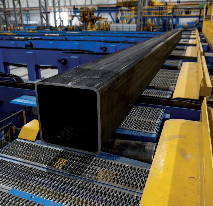
Jumbo HSS – go taller and higher. Atlas Tube is the only producer of Jumbo HSS in North America. And the size range we offer is unmatched. The strength-to-weight ratio of this product enables uniform strength no matter the height and enables builders to go taller and wider with greater aesthetic appeal. With Jumbo HSS, its possible to go greener by using less overall steel in a structure.
Our Jumbo HSS offer exceptional cost-effectiveness for com mercial and industrial construction, including factories, industrial structures, high-rises, and sporting stadiums.
Shuriken™ “Better Bolted Connections”. Atlas Tube’s proprietary Shuriken technol ogy helps our customers make better bolted connections and allows field bolting for any application where access to both sides of a connection are limited.
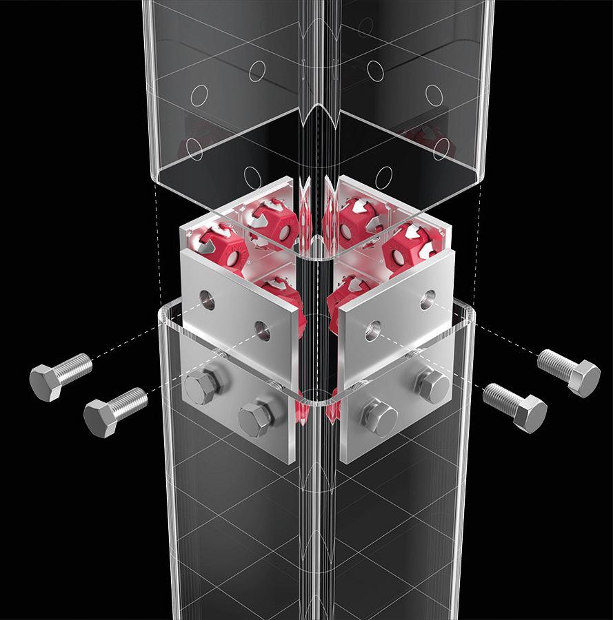
Shuriken allows fabricators to pre-install a nut in the shop in hard-to-reach places, so contractors can field bolt what would otherwise have to be field welded. No labor-intensive and time-consuming field welds. And bolted connections can help accelerate field inspections. Shuriken is one more way Atlas Tube helps customers deliver projects on-time.
Pipe Piles – Ready2Drive™ on your schedule. Atlas Tube pipe piles have a long track record of success in projects throughout North America in both the public and private sectors. We provide complete mill test reports for quality assurance and exceptionally quick turnaround, with 4-6 week rolling cycles and drop-in roll ing capabilities available.
We provide a full range of services for our customers, including welders certified through the American Welding Society (AWS) and Canadian Welding Bureau (CWB). Atlas pipe piling product can arrive at the job site Ready2Drive with the fabrication your piling contractor needs.
We help you keep your project on track before we ship. Services for pipe pile customers include bevel cutting, length cutting, welding, and application of accessories ranging from driving shoes and splicers to flanges.
AIM – Increasing Channel Efficiency for Project Success. Atlas Tube offers customers proprietary AIM technology so they can have the right amount of stock on hand while carrying less overall inventory. Old ways of managing inven tory waste time, tie up cash and take up warehouse space. AIM provides our channel partners with a higher level of efficiency, flexibility, and control, so that your projects can be delivered on time. One more way Atlas Tube delivers service others do not approach.
Not vendors, partners. We work closely with the full project team, from design through delivery, in all the ways that matter to assure their success with those they serve. Get in touch to learn more about how Atlas Tube can help you build smarter, more sustainably, and help manufacture a better future.
Phone: 314-851-2200
Email: answers@mii.com Web: www.mii.com/ultra-span
Product: Ultra-Span® Trusses, Steel Engine™
Description: Enable your building to be stronger, longer-lasting, and more resilient for the duration of its life with the strength of MiTek’s Ultra-Span CFS and industry-leading design software, Steel Engine. MiTek collaborates across the building industry to enable and accelerate transformational breakthroughs in design and construction, both on-site and off-site.


Phone: 260-969-3500
Email: joe.voigt@newmill.com Web: www.newmill.com
Product: Steel Joists and Metal Deck
Description: Achieve architectural visions. Solve engineering challenges. Realize project goals. Your success begins with selecting the right steel building system. From steel joists and deck to long-span composite floor systems, we engineer and manufacture solutions that control costs, enhance performance, and ensure project success. Together, let’s build it better.
Phone: 949-951-5815
Email: candicec@risa.com Web: risa.com
Product: RISA-3-D
Description: The best choice for the design of all things steel. Whether designing custom hot rolled steel shapes or cold-formed steel wall panels, RISA-3D has you covered. With steel databases and design codes from all over the world, you will never have to look anywhere else.

Phone: 609-592-2565
Email: info-na@schoeck.com Web: www.schoeck.com
Product: Isokorb® Structural Thermal Break T Type S
Description: A load-bearing thermal insulation element for steel connections, such as balconies, canopies, beams, and rooftop applications (solar panel equipment, HVAC systems, etc.). It accommodates normal as well as shear forces. Moments can be transferred by using a minimum number of two modules.
Phone: 678-737-7379
Email: jodi.hendrixson@trimble.com Web: www.tekla.com/us
Product: Tekla Structures
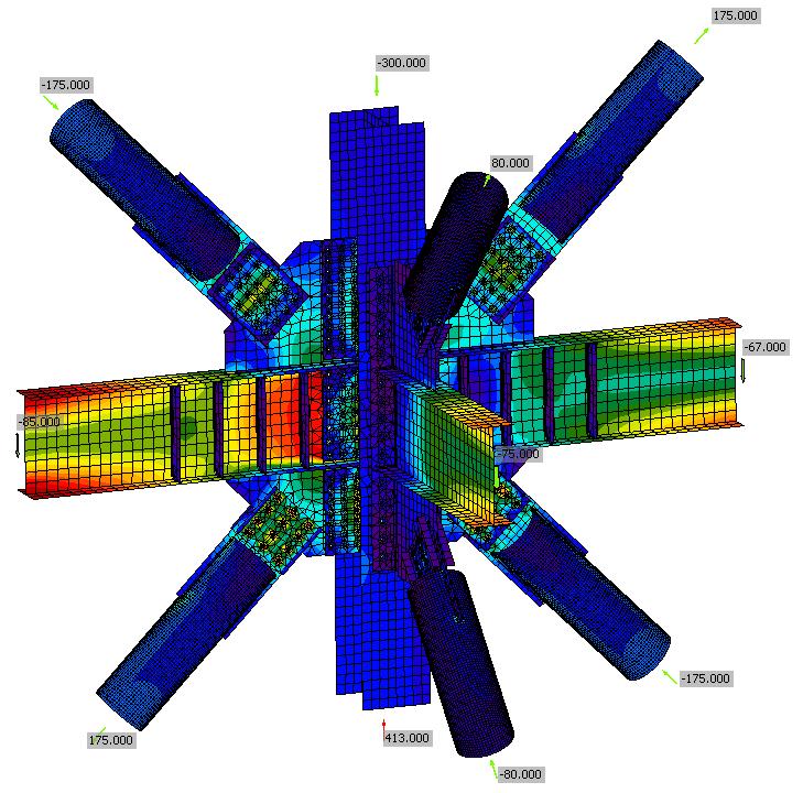
Description: Create a detailed, constructible 3-D model of any steel structure from industrial and commercial buildings to stadiums and high-rise buildings. Tekla Structures enables collaboration and sharing of project information among architects, engineers, and contractors and links with major AEC, MEP, and plant design software.
WoodWorks®
Phone: 800-844-1275
Email: sales@woodworks-software.com Web: www.woodworks-software.com

Product: WoodWorks Software
Description: Conforms to IBC, ASCE 7, NDS, and SDPWS. SHEARWALLS: designs FHS, FTAO, perforated shearwalls; automatically generates loads; rigid and flexible diaphragm analyses. SIZER: designs beams, joists, columns, studs, and CLT up to 6 stories; automatic size optimization. CONNECTIONS: Wood-to-wood, -steel, or -concrete.
IDEA StatiCa is the world-leading solution for the structural design of steel connections, concrete details, and critical members. Our applications are desktop and cloud-based and enable structural engineers in more than 110 countries worldwide to accurately design structural components, which they had estimated before.
We develop software for structural engineers and detailers. Our development team researches, tests, and applies new methods of analyzing the behavior of structures and their members. Based on this, we created IDEA StatiCa – software that enables engineers to work faster, evaluate requirements of national codes thoroughly, and use the optimal amount of material. For us, creating software is a way to contribute to making every new construction around the world safer and more cost-efficient.
There are many great tools out there to help save engineers’ time when it comes to steel connection design. Currently, about 80% of the connections on a project take only about 20% of the overall connection design time. That last 20% of connections take the other 80% of the time. These are going to be the more complicated connections that typically cannot be designed with the engineer’s current toolkit, so he must revert to good old hand calculations or possibly spreadsheets, as well as engineering judgment. Now there
is a connection design soft ware that can manage these more complex connections as well as the simple ones, IDEA StatiCa.
What makes IDEA StatiCa different is that we perform finite element analysis on the connection; this means no limitations on connec tion geometry or structural sections. Instead of creating individual models for each plane of the connection, IDEA StatiCa allows you to look at the entire joint at one time and understand how it behaves. Thanks to our software, our users confirm that they are saving days and weeks, not only hours, on their projects.
IDEA StatiCa can help you streamline your connection design because it works with many structural analysis tools (RAM, RISA, TSD, CSI, etc.) and BIM and detailing software. In addition, you can use the model you have already built to provide the basic information and modeling so that you can focus on the actual connection details.
Structural engineers have been achieving project success with New Millennium since 1999, when we set out on our mis sion to be a trusted collaborator for the design, engineering, and supply of structural steel joists and steel deck building systems. A wholly owned subsidiary of Steel Dynamics Inc., we have proven ourselves as a premier provider of cost-efficient, high-performance structural steel joist, joist girder, and roof and floor deck solutions for commercial steel construction in the U.S. With seven manufac turing facilities across North America, we are built for collaborative, expedited project delivery. Our steel building systems specialists have decades of experience and stand ready to offer valuable assistance. When working with structural engineers, we are a collaborative resource. We assist you right from the start in specifying and engineering the building system best suited for your project. We engineer and manufacture solutions that control costs, enhance performance, and ensure project success.
Steel joists and joist girders are key components of the most costeffective, performance-optimized structural steel building systems. Our specialists provide early design and engineering assistance to help streamline the specification of the right joists to simplify and expedite the delivery of more cost-efficient projects. All our steel joists and joist girders are engineered and manufactured in accordance with the specifications of the Steel Joist Institute.
• Standard steel joists and joist girders: Primary and secondary framing members, steel joists, and joist girders support uniform and concentrated loads for roof or floor systems. We engineer and manufacture a range of joists and girders for various applications.
• Special profile joists: Profiles include gable, bowstring, arched, scissor, and double-pitched joists. Our leading development of engineering specifications enables over 40,000 special profile steel joist design possibilities.
• Composite joists: Stronger, lighter, and efficient, composite joists create the longest spans possible. They get their strength from an overlying concrete slab that creates a unified load-bearing system that deflects as a single unit.
• WN Series™ joists: For wood-on-steel roof systems, these joists are stronger, stiffer, and more efficient. A continuous wood nailer with glued finger joint splices provides structural continuity for the entire length of the joist.
For your structural and architectural needs, New Millennium manufactures a range of steel roof and floor deck profiles with a variety of finishes. Our team assists you in determining the ideal deck for your project.
To meet architectural needs, steel roof and floor deck can combine with exposed structural frames to create striking, spacious interiors and dramatic, high-performing exteriors. Optional acoustical
treatments absorb sound energy. Applications readily integrate lighting, electrical, plumbing, and fire suppression systems.
For multi-story construction, our long-span composite floor deck systems address multiple factors, including space planning; struc tural need; fire, vibration, and acoustic ratings; and obstruction-free MEP service installations. These systems optimize the cost and per formance of your mid-rise or high-rise project. They achieve clear spans up to 36 feet. They can weigh up to 40% less than comparably utilized cast-in-place concrete floors. They minimize floor depth and optimize floor-to-floor height. They reduce project costs and accelerate construction timelines.
Structural engineers have two options for steel stay-in-place bridge deck forming systems at New Millennium. Both are suitable for new construction and rehabilitation of concrete or steel bridge structures.
• Bridge-Dek®: Made of high-strength galvanized steel with factory-closed ends that speed installation, Bridge-Dek creates a safe working platform after installation, reduces costs by 20% to 25% compared to wood forms, and integrates with steel or concrete girders.
• Rhino-Dek®: Ideal for spans over brackish and salt water, Rhino-Dek has a polymer laminate – available on one or both sides of the deck pan – over galvanized steel to protect exposed steel from salt corrosion. It has a service life of 124 years.
To help make engineers’ jobs easier, we offer a range of informa tional and educational resources.
• Catalogs: Our downloadable catalogs for steel joists and steel deck enable you to work quicker, not harder.
• Online design tools: Interactive steel joist and steel deck design tools help transform your design process, increasing project performance and reducing project costs.
• Credit-hour courses: Our continuing education courses are offered in three calendar-friendly formats: live remote, on-site, and on-demand. All courses award AIA and PDH credit. Courses are customized or tailored to your interests and needs. You’ll learn from experienced education specialists and advance your knowledge of steel building systems.
Solve engineering challenges. Realize project goals. Control costs. Your success begins with the selection of the right steel building system – and the right supplier – for your application. We at New Millennium will help you determine the optimal structural steel building system for your application. Together, let’s build it better.
Founded in 1987 in Albion, Nebraska, AGI Sentinel Building Systems has grown from a one-person operation to a premier provider of all-steel buildings in the U.S. Recognized for their quality and expertise, AGI Sentinel provides completely customized building solutions guaranteed to provide a long life of service.
AGI Sentinel All-Steel Buildings offer a customizable solution suitable for commercial, agricultural, and self-storage markets. All buildings are individually designed to customer specifications and requirements. AGI Sentinel focuses on the details from structural requirements to weather tightness.
Manufactured in the Midwest USA, AGI Sentinel offers a hasslefree experience from start to finish. When it comes to service, AGI Sentinel doesn’t run from issues – they fix them. AGI Sentinel customers are partners for life and are treated with the respect and professionalism they deserve, even after the sale is complete.
A steel structure can last for decades. Building with steel provides a durable and reliable structure that withstands harsh environmental conditions and pests that damage integrity over time. Buildings made of steel require less maintenance than other building materials. Steel components are not susceptible to rot or damage from termites and other pests. Colored steel coatings do not require repainting and are easily cleaned with water and detergent.
from several colors and trim options that allow you to brand your building, creating a perfect blend of function and form.
• 26- Gauge Wall & Roofing Panels
• Windows
• Interior Finishing
• Overhangs, Gutters, and Downspouts
• Wainscot
• Doors
• Insulation
• Exterior Facades
AGI Sentinel controls the entire process to ensure the highest quality final product. All design, engineering, and manufacturing are controlled in-house by experienced and knowledgeable professionals. AGI’s Sentinel’s staff work with you through every step to ensure your dream building is brought to life, reducing cost and increasing performance where possible.
e highest quality raw materials are used to manufacture individual building components. AGI Sentinel uses state-of-the-art tools and processes to ensure the strength and durability of each component.


AGI Sentinel takes pride in following industry building standards. Customers trust the quality of AGI Sentinel buildings, knowing certified experts carefully inspect each product. As a member of the Metal Building Manufacturers Association (MBMA), AGI Sentinel is proud of the commitment made to staying on top of all industry changes and required standards.
AGI Sentinel’s All-Steel Buildings are much stronger than any wooden counterpart. Steel has the highest strength-to-weight ratio of any material, about 25 times greater than wood. A lighter frame translates into a more cost-effective foundation and the ability to add additional materials with less concern for the total building weight.
Designed for quick and easy installation, AGI Sentinel products save you time and money on the back end. Compared to many “lower-priced” competitors, AGI Sentinel exceeds in performance while offering a similar total project cost.
AGI Sentinel’s All-Steel Buildings are incredibly versatile, allowing for customization to meet the needs of each individual customer.
Select from a wide array of quality features and optional accessories to improve functionality and enhance appearance. Choose
An accreditation received from the IAS has certified AGI Sentinel’s ability to design and fabricate custom-engineered metal building systems. All buildings meet all requirements in IAS Accreditation Criteria AC 472, International Building Codes, and all other related standards.
AGI Sentinel buildings are designed and fabricated according to AISI and AISC specifications. Additionally, AGI Sentinel engineers are registered professionals, and AGI Sentinel welders are AWS certified.
Are you interested in learning more about AGI Sentinel All-Steel Building products? Visit our website to learn more about our commercial and agricultural products. en, reach out to our sales team to begin designing your dream all-steel building!
Adhesives Technology Corporation
Phone: 754-399-1057
Email: atcinfo@atcepoxy.com
Web: www.atcepoxy.com
Product: CONVERGENT Concrete Densification and Finishing Products
Description: Adhesives Technology Corporation has acquired Convergent Concrete Technologies, the industry leader in concrete densifiers, hardeners, and finishes. ATC now offers Pentra® products, including Nano-Lithium® technology and Reactive Silicon Hybrid Polymers, and new silica-free, Strontiumbased STRiON® formulas. From densifiers and cures to hardeners and paints, ATC provides innovation engineered to outperform.
ASDIP Structural Software

Phone: 407-284-9202 Email: support@asdipsoft.com Web: www.asdipsoft.com
Product: ASDIP FOUNDATION
Description: Design concrete footings, such as isolated spread footings, two-column combined footings, strap footings, wall footings, and pile caps. See immediate graphical results, calculations, and detailed or condensed reports with exposed formulas and code references. ASDIP FOUNDATION easily integrates with ETABS and other software to optimize your designs in minutes.
Geopier ® Foundation Company

Phone: 704-439-1790
Email: info@geopier.com
Web: geopier.com
Product: Geopier Rammed Aggregate Pier® and Rigid Inclusions
Description: Geopier provides an efficient and costeffective Intermediate Foundation® solution for the support of settlement structures. Our systems have become effective replacements for massive overexcavation and replacement or deep foundations, including driven piles, drilled shafts, or augered cast-in-place piles. Thousands of structures around the world are currently supported by Geopier technologies.
Phone: 630-406-0600
Email: grippleinc@gripple.com Web: www.gripple.com
Product: Terra-Lock

Description: Unique plate and anchor kit to secure a variety of TRM and HPTRM erosion control and slope stabilization matting. Proprietary design, easy to install, and open plate promotes vegetation regrowth.
Listings are provided as a courtesy, STRUCTURE is not responsible for errors.
IES, Inc.

Phone: 800-707-0816
Email: info@iesweb.com
Web: www.iesweb.com
Product: IES VisualFoundation
Description: You need rock solid foundation design? IES offers easy structural software, like VisualFoundation. Quickly model mat slabs, pile caps, and grade beams. Get stability checks, handle punching shear, and make smart code-compliant designs. Try it free, watch videos, find product benefits and pricing at website.
RISA Technologies
Phone: 949-951-5815
Email: candicec@risa.com
Web: risa.com
Product: RISAFoundation
Description: Designs retaining walls, two-way mat slabs, spread footings, grade beams, and pile caps all within an open modeling environment. With synchronized load transfer from RISA-3D and RISAFloor models, foundation design has never been easier. Punching shear checks, rebar design, and international codes make it the smart choice for engineers.
Eliminate pour strips, wall restraint, and expansion joints – and the extra costs, construction delays, and safety issues they bring – with the PS=Ø Mechanical Reinforcement Splice System
The PS=Ø Mechanical Reinforcement Splice System eliminates pour strips, wall restraint, and expansion joints while allowing for volume change in the slab and providing structural integrity. Using proven coupler technologies recognized worldwide, the PS=Ø system features a thread on one end and a grout-filled sleeve on the other. The system is an ACI-permitted Type 1 and Type 2 mechanical splice, is ICC-approved, and made in the USA.
Closing pour strips and wall leave-outs are a project’s most expensive concrete pours. Formwork, shoring, and backshoring must stay in place for long periods of time, and crews must be reassembled for small pours. The PS=Ø system eliminates these costly and timeconsuming steps.
Pour strips and wall leave-outs are a drag on any construction schedule. They not only require re-pouring the leave-out but also restrict worker access. The PS=Ø system can cut weeks or even months from construction schedules by eliminating pour strips and wall leave-outs.
An open leave-out in a floor is a significant safety hazard. Pour strips are particularly hazardous because they run the entire width of the slab and are impossible to avoid. The PS=Ø system replaces dangerous leave-outs with small, grouted joints. Eliminate pour strips, wall restraint, and expansion joints with the PS=Ø Mechanical Reinforcement Splice System.
Phone: 754-399-1057
Email: atcinfo@atcepoxy.com
Web: www.atcepoxy.com
Product: ULTRABOND® and CRACKBOND® Adhesives

Description: America’s #1 structural adhesive specialist offers four IBC compliant, wind and seismic rated adhesives, including HS-1CC, the world’s strongest anchoring epoxy. The CRACKBOND line of products is a comprehensive collection of products designed for professional concrete repair and restoration. ATC is a Meridian Adhesives Group Company.
American Concrete Institute
Phone: 248-848-3700
Email: acicustomerservice@concrete.org Web: www.concrete.org
Product: Concrete Knowledge Resources
Description: Always advancing – The American Concrete Institute is a leading global authority for the development, dissemination, and adoption of its consensus-based standards, technical resources, and educational, training, and certification programs.
Phone: 407-284-9202
Email: support@asdipsoft.com
Web: www.asdipsoft.com
Product: ASDIP CONCRETE
Description: Advanced software for the design of multi-span continuous beams, biaxial slender columns, concrete/masonry bearing walls, shear walls, one-way slabs, and wall opening design per the latest design codes. ASDIP CONCRETE easily integrates with ETABS and other software to effortlessly optimize your designs with a few clicks.
Phone: 267-702-2815
Email: info-us@dlubal.com
Web: www.dlubal.com
Product: RFEM 6
Description: The all-new RFEM 6 provides strength and serviceability limit state design of beams, columns, and flat/curved plates according to ACI 318, CSA A23.3, and other international standards. Punching shear is also possible for columns, wall ends, and wall corners. View detailed design equations, code references, and 3-D interaction diagram.
Phone: 800-929-3030
Email: info@ctscement.com Web: www.ctscement.com
Product: Rapid Set® Cement
Description: Outperforms other concrete repair materials in durability, repetitive loading, chemical attack, permeability, freeze/thaw, abrasion resistance, and shrinkage. Rapid Set achieves structural or driveon strength in one hour. Use for concrete repairs, restoration, and new construction projects.
Phone: 800-424-2252
Email: info@enercalc.com
Web: https://enercalc.com
Product: ENERCALC Structural Engineering Library (SEL)
Description: SEL quickly completes calculations for the design of footings, columns, beams, pedestals, shear walls, etc. Our 3-D FEM and 3-D sketches let you avoid expensive, hard-to-use software. SEL now includes RetainPro’s concrete earth retention design/ calculation tools. Powerful new design module: General footing by FEM.
Concrete Section continued on page SS-86
CTS Cement manufactures two lower-carbon alternatives to port land cement for the construction and restoration of building and infrastructure structural components: Rapid Set® Cement and Komponent® shrinkage-compensating additive. Both brands are a type of calcium sulfoaluminate (CSA) cement, which emits 33% less CO2 during manufacture than portland cement. In 2022, a Type III environmental product declaration (EPD) was developed for each brand to support project owners’ efforts to use sustainable building materials.
Rapid Set Cement qualifies as very rapid hardening (VRH) per ASTM 1600 (Standard Specification for Rapid Hardening Hydraulic Cement) and can achieve 4500 psi compressive strength at 1.5 hours. Unlike other CSA cements, it doesn’t require blending with portland cement or accelerators. Mixed, placed, and finished similarly to portland cement concrete, the material saves time and money during construction by lowering installation times and labor requirements.
As a CSA cement, Rapid Set is inherently more resistant than portland cement to deterioration caused by chlorides, alkali-silica reaction (ASR), sulfate attack, and shrinkage cracking. As a result, major structural components require less maintenance and repair, lowering overall lifecycle costs.
Rapid Set Cement is the core ingredient in dozens of cements, mortars, and grouts engineered specifically for the strength requirements of floors, walls, columns, beams, piles, and other structural components.
Komponent is a shrinkage-compensating additive blended with local portland cement and aggregates to make ASTM C845-compliant Type K shrinkage-compensating concrete and grouts for transporta tion, tunnel, water and wastewater containment, industrial floor, and commercial building. In addition to thwarting curling and cracking caused by drying shrinkage, the additive enables design engineers to reduce or eliminate control joints significantly.

Rapid Set Cement- and Komponent-based products have been used to build such landmarks as the Hoover Dam Bypass, the Pentagon, the Lincoln Tunnel, and the San Francisco-Oakland Bay Bridge, as well as major roadways, airports, commercial, and industrial projects worldwide. Research by departments of transportation (DOTs) nationwide confirms the durability of decades-old placements.
Our team of material scientists, engineers, technical experts, and field representatives work with you every step of the way, from design through construction, to ensure your success. Contact us for assistance with product selection, specifications, samples, and mix designs.
When you choose to build with concrete, you are creating something that stands the test of time. What’s most important, however, is the time spent before you pour the first drop. A powerful yet free resource, the Concrete Design Center can help set you up for success from the very beginning. Our technical experts help with structural system selection, concrete specification review, cost estimating, energy analysis, and green building standards for:
Multi-family
Education
Healthcare
Hotels
motels
Industrial and Commercial
Concrete
Tilt-up
Insulating Concrete
Tunnel forms
After our team completes their review, you’ll receive a compre hensive document with their recommendations and side-by-side comparisons of different structural systems.
Structural system selection: Our expert team assists you when choosing the right concrete system for your project to maximize the advantages of concrete, including economy, resilience, and sustainability.
Concrete specification review: When it comes to concrete, structural engineers have a significant impact on product formu lation. Our expert team can review your concrete specification to ensure you optimize for quality, strength, economy, and sustain ability through performance-based specifications.
Cost estimating : We help to assemble a team of contractors and concrete suppliers to estimate the cost of building with concrete to meet your upfront and long-term budget needs.
Green building: Our green building experts can help optimize for low-carbon concrete, LEED certification, and other green building standards when using concrete building systems. We demonstrate how concrete systems impact energy, life cycle assess ment, environmental product declarations, noise reduction, and indoor environmental quality.
Training and tours: A great place to learn more about building with concrete is at one of our many events, from roundtable discus sions to seminars and site tours. Meet industry experts who share their experiences and get the training you need to start building your own concrete project.
When budgets are thin and timing is tight, it is easy to get caught up in the initial costs. But using the wrong materials can actually cost you more in the long run. With concrete, you know that what you build is going to be secure from day one. There is simply nothing safer or stronger – and that’s worth the investment:
Energy efficiency: Concrete can save 30% or more in annual energy costs compared to other building systems.
Resources that last: Starting with a strong material like concrete means you actually need less – and get more – helping you save on upfront costs.
Durable and resilient: Concrete is one of the few materials that can out last natural disasters and stand up to man-made threats.
Lifecycle savings: Structures built of quality materials last longer, with lower overall lifecycle costs.
Strength for the ages: Concrete structures can last for centuries because concrete only gets stronger over time, unlike other materials.
Fire resistant: A fire-resistant structure, combined with other fire safety requirements, can exceed building requirements – instead of just meeting them.
Phone: 678-333-4450
Email: robbie.hall@hrc-usa.com Web: www.hrc-usa.com
Product: High Performance Reinforcement Products

Description: High-performance T-Headed Bars, Mechanical Splices, and other related products specified for use on projects with demanding applications such as seismic-, impact-, and blastresistant loading conditions. HRC has been providing headed reinforcing bars since 1985 and the ultimate performance of our products should be a standard requirement in your design.
Hohmann & Barnard
Phone: 800-645-0616 Email: jenniferm@h-b.com Web: h-b.com
Product: Thermal Concrete 2-Seal™ Wing Nut
Description: An innovative single screw veneer tie for concrete, CMU, or wood stud construction. The anchor features a dual-diameter barrel with factoryinstalled EPDM washers to seal both the face of the insulation and the air/vapor barrier, and unique Thermal Wings that are designed to decrease thermal transfer through rigid insulation.

Phone: 800-707-0816
Email: info@iesweb.com Web: www.iesweb.com
Product: IES ConcreteSection
Description: For $10/month, you can use IES ConcreteSection to understand custom reinforced concrete shapes. Determine shape capacity and cracked behavior with this easy-to-use desktop software tool. Get a free trial to see for yourself how fast and easy it is to construct shape with embedded steel shapes or rebar.
MAX USA Corp.

Phone: 800-223-4293
Email: yasaba@maxusacorp.com Web: www.maxusacorp.com
Product: PowerLite® System
Description: Power beyond the limits of standard 100 PSI pneumatic tools with the PowerLite system. Designed with a lightweight body and engineered for heavy-duty applications, PowerLite tools are built to shoot through steel, concrete, and engineered woods.
Web: www.buildwithstrength.com/design-center
Product: Concrete Design Center
Description: A powerful, free resource, the Concrete Design Center can help set you up for success on your next concrete project from the start. Our technical experts help with structural system selection, concrete specification review, cost estimating, energy analysis, and green building standards for concrete buildings. Build with strength…build with concrete.
Phone: 949-951-5815
Email: candicec@risa.com Web: risa.com
Product: Adapt-Builder
Description: A powerful and easy-to-use 3-D finite element software for multistory reinforced concrete and post-tensioned buildings and structures. Builder delivers comprehensive workflows for complete analysis and design. Combine gravity, lateral, and post-tensioning actions for efficient, complete, and accurate design. Integrate with various BIM software for seamless project deliverables.
MAX, the original inventor of the battery-operated rebar tying tool, offers the most advanced rebar tying tools to concrete contractors with the TWINTIER® series.
The new TWINTIER models adopt new technologies that have not been incor porated into earlier models, including increased tie speed. The TWINTIER series tie at approximately ½ sec per tie, reducing the time spent on repetitive snap-tying. The robust 5.0 Amp lithium-Ion battery enables the TWINTIER RB441T to sup port 5,000 ties per charge. Each of the MAX TW1061T series tie wire spools can tie up to approx. 240 ties (when tying #4 x #4 rebar) before reloading. Equipped with the new wire pull back mechanism, each TWINTIER tie dispenses only the amount of wire needed for each rebar combination. This reduces unnecessary wire waste and provides much stronger ties than conventional rebar tying tools. The TWINTIER wire bending
mechanism enacts individual wire tie tips that are automatically pushed down, allowing for shallow concrete pours. At only 5.6 pounds, the RB441T provides single-handed operation awarding operators the ability to use their free hand to adjust rebar in place or to support the weight of their back while bending over to tie flatwork.
MAX offers a complete line of TWINTIERs relative to the type of rebar tying application you are employing. Our RB611T model provides the greatest capacity rebar tying tool on the market today, tying up to #9 x #10 rebar. For extensive flat work job sites, MAX’s RB401T-E Stand Up TWINTIER grants the operator the ability to stand up to tie rebar without assuming the discomfort of continual bending or pulling of the trigger. As the world’s first battery-operated stand-up rebar tying tool, the RB401T-E can help to reduce the risk of back strain and repetitive motions, thus reducing job site injuries.
Phone: 855-572-4625
Email: info-na@schoeck.com Web: www.schoeck.com
Product: Isokorb® T Type CD Structural Thermal Break
Description: A load-bearing thermal insulation element for cantilever concrete slabs such as balconies. It transfers bending moments and shear forces. Thermal breaks can be used to isolate and attach mild reinforced concrete balconies to post-tensioned interior slabs.
Product: Schöck Bole® SR.

Description: Easy to install, Schöck Bole SR provides an efficient punching shear reinforcement solution when reinforcing concrete slabs with shear studs. It guarantees optimum force resistance around columns and prevents punching shear failure. The punching shear reinforcement element is easy to install, either at the prefabricating plant or on site.
Phone: 276-645-8000
Email: info@strongwell.com Web: www.strongwell.com

Product: GRIDFORM™

Description: A prefabricated fiber reinforced polymer (FRP) double-layer grating, concrete-reinforcing system with integral stay-in-place (SIP) form for vehicular bridge decks. The lightweight GRIDFORM panel, which weighs only 4.7 pounds per square foot, is shop-fabricated in units that are limited only by shipping constraints to approximately 50 by 8 feet.
Product: SAFSTRIP®
Description: A pultruded composite strip that improves the strength of an existing structural member when mechanically fastened to the structure. The reinforcing strip has high bearing and longitudinal properties and is designed to strengthen the flexural capacity on the tension face of concrete girders, slabs, and decks.
Our
Guide
Phone: 678-737-7379
Email: jodi.hendrixson@trimble.com Web: www.tekla.com/us

Product: Tekla Tedds
Description: A powerful software that will speed up your daily structural and civil calculations, Tekla Tedds automates your repetitive structural calculations. Perform 2-D Frame analysis, utilize a large library of automated calculations to U.S. codes, or write your own calculations while creating high quality and transparent documentation.
Williams Form Engineering Corp.

Phone: 616-866-0815
Email: williams@williamsform.com Web: www.williamsform.com
Product: All-Thread-Bar
Description: Williams Form Engineering Corporation has been providing threaded steel bars and accessories for rock anchors, soil anchors, high capacity concrete anchors, micropiles, tie rods, tiebacks, strand anchors, hollow bar anchors, post tensioning systems, and concrete forming hardware systems in the construction industry for over 100 years.
CRSI is making it easier to design and build in reinforced concrete with helpful technical information, design guides and checklists, field publications, and reference documents.
Founded in 1924, CRSI is a technical institute and an ANSIaccredited Standards Developing Organization (SDO) that stands as the authoritative resource for information related to steel reinforced concrete construction. Among the Nation’s oldest trade associations, CRSI authors many industry-trusted technical publications, stan dards documents, design aids, reference materials, and educational opportunities to advance and standardize the reinforced concrete construction industry.
CRSI’s members represent over 80% of U.S. manufacturers, fabri cators, and placers of steel reinforcing bar and related products with over 600 locations in 49 states and over 15,000 employees. Members produce, fabricate, and install approximately nine million tons of reinforcing steel annually using scrap steel in efficient manufacturing operations. It is estimated that the industry impacts over 75,000 people in steel transportation and placement in North America.
Our professional members (architects, engineers, contractors) are involved in the research, design, and construction of steel reinforced concrete structures.
CRSI also has a broad Region Manager network that supports both members and industry professionals and creates awareness among the design/construction community through outreach activities.
Recently, CRSI launched a landing page based on their new tagline, Safe and Sound: Steel Reinforced Concrete. The web page provides quick information on the world’s most common building material and acts as a vehicle to address, inform, and respond to pressing industry topics. Several issues have been addressed on the page, but more relevant content is planned. Visit the page at www.safeandsoundsrc.com
Please visit the website for more information and to view all of CRSI’s popular publications and free technical information.
Phone: 754-399-1057
Email: atcinfo@atcepoxy.com
Web: www.atcepoxy.com
Product: ULTRABOND® and CRACKBOND® Adhesives

Description: America’s #1 structural adhesive specialist offers four IBC compliant, wind and seismic rated adhesives, including HS-1CC, the world’s strongest anchoring epoxy. And CRACKBOND ACCUGROUT HD is a high strength grout designed for onshore and offshore wind farm installations. ATC is a Meridian Adhesives Group Company.
Cast Connex
Phone: 888-681-8786 Email: info@castconnex.com Web: www.castconnex.com
Product: High Strength Connectors™
Description: Standardized, capacity-designed brace end connectors that accommodate bolted double-shear connection between round HSS braces and a typical corner gusset plate.
Product: Cast Bolted Brackets
Description: Prequalified connectors for special and intermediate steel moment frames per AISC 358. Can be used in the retrofit of seismically deficient steel moment framed buildings or in new construction.
Phone: 801-727-4060
Email: contact@durafuseframes.com
Web: www.durafuseframes.com
Product: DF360
Description: DuraFuse Frames’ products are unique seismic resilient systems preventing beam and column damage while also providing repairability. DuraFuse Frames offers the ideal moment-frame and dual-frame solutions for all building types in all Seismic Design Categories and provides the most versatile SMF/IMF system on the market in addition to resiliency.
Phone: 800-424-2252
Email: info@enercalc.com Web: https://enercalc.com
Product: ENERCALC Structural Engineering Library (SEL)
Description: SEL automatically incorporates seismic loads in load combinations, including the vertical component, redundancy, and system overstrength factors, as applicable. Supports ASCE 7’s Base Shear, Demands on Non-Structural Components, and Wall Anchorage. SEL subscriptions are now available for all 7 retaining wall modules (including substantial segmental wall improvements) and ENERCALC 3D FEM.
Phone: 800-645-0616
Email: jenniferm@h-b.com
Web: h-b.com
Product: HB-213 SH Seismic Veneer Anchor
Description: Comprised of the HB-213 Adjustable Veneer Anchor and H&B’s Seismic Hook, the hook is “swagged” (indented) in two places to accommodate either a 9-gauge or 3⁄16-inch continuous wire. The indentations form a channel that braces the continuous wire and holds it in place.

Phone: 406-586-8988
Email: info@iesweb.com Web: www.iesweb.com
Product: IES Building Suite
Description: For less than $200/month, get easy tools to help with lateral design for wind or seismic loading. Tackle foundations, structural frames, and connections. VisualAnalysis provides practical ways to load structures and understand behavior. Design your next project with the IES Building Suite.
DuraFuse Frames® are steel moment connections with oneof-a-kind resilience, exceptional performance, and economy. Seismic energy is dissipated through an innovative fuse plate which prevents beam and column damage. The bottom flange fuse plate and all-bolted erection minimize post-earthquake repair duration and cost. Full-scale laboratory and shake table testing have confirmed the performance and easy repairability. Repairable DuraFuse con nections apply to both new construction and retrofit of existing buildings. The benefits of selecting DuraFuse include:
• Reduction of downtime and repair costs by up to 65% following a severe earthquake (i.e., improved functional recovery)
• Connection configuration and design optimization results in frame weight reduction as compared to all other moment frame systems
• Significant reduction (up to 70%) in seismic lateral beam bracing requirements
• A completely field-bolted connection eliminates field welding and associated inspections
• Fewer parts, less fit-up, and less connection weight compared to other proprietary moment connections
• Complimentary design support from the DuraFuse engineering team
DuraFuse connec tions are prequalified in AISC 358-22 and fully comply with per formance requirements in AISC 341 with code approvals from IAPMO UES ER 610, including 2018 IBC, 2019 CBC, and 2020 LABC Supplements. Multiple Technical Bulletins have been published to provide additional performance, modeling, and design resources. Modeling, design, and detailing of DuraFuse Frames are available in RAM Structural Systems, Revit, SDS2, and Tekla. The DuraFuse research, engineering, and design teams are con stantly improving the modeling, analysis, and design process to ensure efficient, high-performance, and resilient design solutions with quick response times. Our team is looking for opportuni ties to work with you. We are happy to provide a resilient design alternative using DuraFuse Frames based on your specifications. If you want to distinguish your next steel moment frame design, we can help you bring economy and repairability, adding value for
clients.


Phone: 510-495-1575
Email: info@quakebracing.com
Web: quakebracing.com

Product: SkinnyBraces
Description: Fits into narrow spaces in soft-story buildings where traditional retrofit methods won’t work. Featuring replaceable “structural fuse” elements that provide predictable, ductile behavior, R=6.5, up to 11.75k capacity in 8- to 13-inch width. Typically shipped for customized installations within five days. Eliminates onsite welding and associated inspections.
RISA Technologies
Phone: 949-951-5815
Email: candicec@risa.com Web: risa.com
Product: RISA-3D
Description: Feeling overwhelmed with seismic design procedures? RISA-3D has you covered with seismic detailing features including full AISC-341/358 code checks. Whether you’re using RISA-3D’s automated seismic load generator, or using the built-in dynamic response spectra & time history analysis/ design capabilities, you’ll get designs and reports that meet all your needs.
Phone: 855-572-4625
Email: info-na@schoeck.com
Web: www.schoeck.com
Product: Schöck Isokorb® T Type CEQ

Structural Thermal Break
Description: A load bearing thermal insulation element for transfer of earthquake loads. This thermal break transfers horizontal shear and tensile forces parallel to the insulation layer as well as uplift forces when used in conjunction with T Type CM STBs in linear connection.
Phone: 678-737-7379
Email: jodi.hendrixson@trimble.com
Web: www.tekla.com/us
Product: Tekla Structural Designer
Description: Built-in loading wizards automatically calculate all wind and seismic forces, generate design cases, and optimize the design of steel and concrete members to the latest AISC, ACI, and ASCE 7 design codes. With Tekla Structural Designer, engineers can review detailed calculations with code clauses and print complete reports for review submittals.
Phone: 888-440-9717
Email: info@tectonus.com Web: www.tectonus.com
Product: Tectonus Self-Centering Friction Dampers (RSFJ)
Description: Revolutionary self-centering friction dampers for any lateral load resisting system in new and retrofit buildings – timber, concrete, and steel. Reduce force demand on the structure and foundations, and benefit from ultimate low damage resilience with no post-event repair. Our expert engineering team support you from project concept to completion.
Williams Form Engineering Corp.


Phone: 616-866-0815
Email: williams@williamsform.com Web: www.williamsform.com
Product: Wind Turbine Foundation Anchor Bolts
Description: Williams Form Engineering Corporation has been providing threaded steel bars and accessories for in the construction industry for over 100 years. Each wind tower supported by a Williams foundation anchor bolt can be relied upon to perform flawlessly throughout the life of the turbine.
Tectonus makes a revolutionary self-centering friction damper, trusted by engineers in Japan, New Zealand, and Canada. Several U.S. projects are in the planning stages.
Tectonus devices offer damping and self-centering all-in-one, conferring significant advantages and flexibility to structural designers. Buildings engineered with Tectonus can be lighter and thus less susceptible to seismic damage with faster functional recovery.
Applications:
• Braces – tension/compression and tension only
• Shear wall
• MRF
• Steel, timber, and concrete
• Retrofit and new build
Pre-earthquake benefits:
• Every unit is performance tested and certified
• No maintenance required (visual inspection at
• Can decrease construction time
• Can lower force demand, thereby lowering
Post-earthquake advantages:
• Fully elastic to design level earthquake
• No post-event repair or maintenance
• Eliminate costly structural repair, replacement work
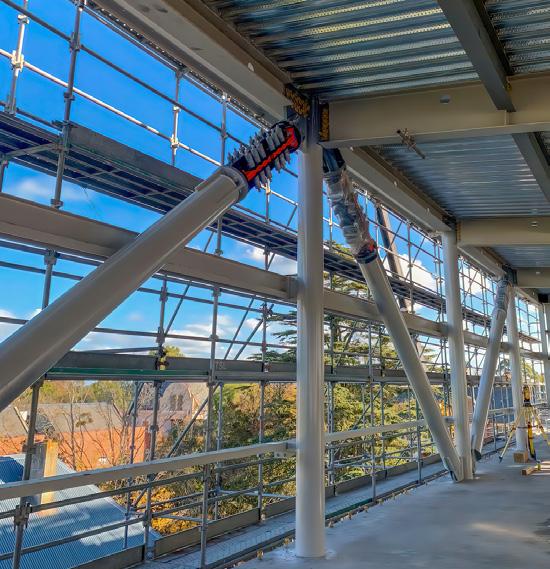
• Accelerated functional recovery
Production Testing:
Given that Tectonus devices do not get damaged, 100% production testing is carried out on every single device. In addition, Tectonus provides a performance certificate for every unit shipped.
Engineering design support:
Tectonus’ dedicated engineering team is ready to support projects from concept to finish. Contact us for further information, presentations, and project support.
66years of leadership in structural engineering, a steadfast dedication to service, technical expertise, and longstanding customer relationships enable Simpson Strong-Tie to understand the operational dynamics of the construction industry. We use this knowledge to develop advanced solutions for structural steel. Our innovative products and technology help everyone –from fabricators and erectors to building owners, engineers, and contractors – maximize efficiency and resiliency at every stage of the building process.
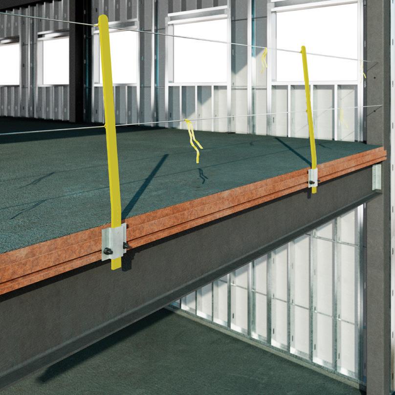
Like our customers, Simpson Strong-Tie is always looking for innovative ways to design and build safer, stronger structures. So we are excited to introduce the Edge-Tie system for cladding and curtain-wall connections in structural steel construction. As we continue to expand our portfolio of products and solutions for the structural steel industry, the Edge-Tie system provides an innovative solution for fabricators, erectors, engineers, building owners, and contractors.
The Edge-Tie system is designed with a unique, extruded steel beam shape and pour stop combination that provides higher strength than traditional bent plates. This revolutionary design utilizes Edge-Tie system T-bolts that allow installers to position and adjust anchors along a continuous channel easily. As a result, field welding is eliminated, saving valuable time and labor costs during construction while, at the same time, enhancing safety and speeding up building enclosure.
For engineers and fabricators, the Edge-Tie system simplifies anchor attachment planning. If small adjust ments are needed during construction, which is a common occurrence, install ers can easily reposition the bolted connection by sliding it into place along the steel channel. Stronger than bent plates, the Edge-Tie system allows increased cladding loads at a lower installed cost. It is also easy to specify because the Edge-Tie system fits any steel building with no height limitations.
Contractors who attach façades, such as glass or other building envelope exteriors, can hang clips faster than ever with the Edge-Tie
system. Thanks to the bolted connection, installation time and effort are significantly reduced. In addition, the Edge-Tie system guardrail can be attached, without field welding, while the beam is fabricated in the shop or at the job site. This guardrail provides fall protection, reduces tie-off occurrences, and can be reused on other projects.
Building owners and operators will appreciate how the EdgeTie system helps to reduce overall project schedules and labor costs while accelerating building enclosure. The sooner a com mercial structure is finished, the more quickly it can be leased and occupied.
Simpson Strong-Tie has been a leading innovator and partner in the construction industry for over 65 years. Working with us in steel con struction, builders have direct access to products, technology, training, and services that can help maximize efficiency and resiliency at every stage of the engineering and construction process.
Like our other solutions, the EdgeTie system is rigorously tested, proven, and backed by expert technical and field support. We also provide a wide selection of software and web applica tions that help streamline design and detailing.
You can specify the Edge-Tie system for new build or retrofit projects by contacting your Simpson Strong-Tie representative. To learn more about the Edge-Tie system, visit


