INSTITUTIONAL ORGANISATION
THE JUTLAND CORRIDOR
lear ned to s ynergise, optimise and leverage the many for ms of
BENEFITS TO THE LOCAL
Reduces the travel time from Esbjerg to Gothenburg, Stockholm, and Oslo by 30 minutes.
00: 14 OSLO/ GOTHENBURG
S TOCKHOLM
Increases the integrated labour market region by 325,000 people in the working age.
HELSINGBORG
HELSINGBORG
LANDSKRONA
LANDSKRONA
Reduces the travel time from Esbjerg to Copenhagen, Hamburg, and Berlin by 55 minutes.
KØBENHAVN
COPENHAGEN
LUND
MALMÖ
Can manage the 90 % increase in freight trains between Denmark and Sweden that is expe ed a er the opening of the New Nordic fixed link.
HAMBURG
Decreases travel times within the Jutland region significantly and improves commuting opportunities.
government
A 19 kilometers long tunnel between Copenhagen and Esbjerg for long di ance, regional and freight trains.
Lyngvig dune site area 1 : 5000 Bukna orden Esbjerg Nordsøen Lyngvig N B B A A 50 YEAR S PRESEN T
160 M BEACH DUNES SITE RESIDENTIAL 215M 460M SITE AREA AND FLOODING
Section B:B in 1:1000 of site in the present, and predicted site in 50 years



2,0 mm / år 1,8 mm / år 1,6 mm / år 1,4 mm / år 1,6 mm / år 1,2 mm / år 1 mm / år Klim Klitplantage Ve er orup Klitplantage Lyngvig Plantage Svinkløv Klitplantage Fosdal Plantage Langdal Plantage Tranum Klitplantage Blokhus Klitplantage WETLANDS GRASS DUNES SAND GEOLOGY
WATER REED


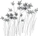

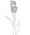
Identification of a sea reed thatching system growing universally in coastal shallows, I’ve situated the project on a Nordic coastline.
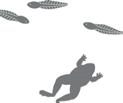

flooding of 1.25 m in extreme rainfall marine sand clay marine sand rich top soil marsh marigold marsh orchid grazers grass clay
is categorized as a diverse beach marshland area facilitating flora/fauna Site as thatch monoculture 20m 0 100m 50m ragged robin perennial herbaceous plant Silene flos-cuculi 1. 2. 3. 4. 5. 5. 6. 6. 6. common heart grass perennial grass Briza media marsh marigold perennial herbaceous plant Caltha palu ris Northern marsh orchid flowering plant Da ylorhiza purpurella Dexter ca le Grå en Dexter ca le farm Bos taurus taurus green-brea ed toad breeds in water holes Bufo viridis 6. 5. 5. 5. water reed BIODIVERSITY
Lyngvig
EXISTING RELATIONSHIP TO REGIONAL URBAN CENTRES


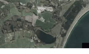
0 0,5 km 1 km 1,5 km 2 km 2,5 km 3 km 3,5 km 4 km 4,5 km 5 km 5,5 km 1:15.000 EXISTING RELATIONSHIPS TO LOCAL INFRASTRUCTURE Former and existing raw material sites. Circle size indicates the production value 0 0,5 km 1 km 1,5 km 2 km 2,5 km 3 km 3,5 km 4 km 4,5 km 5 km 5,5 km 1:15.000 Existing rail networks connecting the port of Esbjerg with rural West Jutland
SITE REGIONAL CONNECTIONS
Situated right at the sea, the region has a mild humid temperate climate with warm summers and no dr y season. Due to the proximity to the sea, the winters are milder than mo other places in Denmark, and the temperatures are more con ant.
The length of the day di ers with more than 1 hours during the year. Dark winters culminate with only 6:11 hours of daylight on the 21 of December, till summer nights with 18:28 hours of daylight on the 20th of June
With the sky and the sea as dominant natural features, the texture of the sky becomes truly important. With mo ly cloudy’ and partly cloudy’ as the main types of cloud cover, counting for over 50% of the time the changing skies are a ver y important a e s of the experience of the place.)
There is a signifiant increase in precipitation during late summer and through the autumn, while the ring is relatively dry in comparison. The number of rainy fays per month relfe s the rainfall of the given month, and the precipitation is mo ly categoriesd as moderate rain, maxing out at almo 18 days of rain in November.
Snow is not an important fa or in the coa al region. With a maximum probably of snow on the ground being 19% and a maximum average snow depth being 8.3 cm
Wind is a defining feature in the dunescape. The average daily wind eed varies between 4 and 5 metres per second (gentle breeze) with the high point in January at 9 metres per second. Prevailing wind dire ion coming from ocean towards the We as apoosed to from Ea ern Fjord
Daylight Clouds
0 min g avg max avg -2 2 -4 4 6 8 I l. 34a Temperatures through the year w th average max. and min. Temperatures 10 12 14 16 18 deg C° J a n F e b M a r A p r M a y J u n J u A u g S e p O N o v D e c 70 21 dec 50 30 10 80 60 40 20 S E 21 mar W N 21 un 20% 10% 0% 30% 40% 60% 50% 70% 80% 90% 100% J a n F e b M a A p r M a y J u n J u A u g S e p O N o v D e c Mi g d t C ea M y l Partly c oudy Mo y c oudy O e ca Sky condition Ill. 34b Sunpath diagram Ill. 34c Cloud-cover d agram Snow Ill. 35b W nd di ribution according to season Wind Precipitation 70 60 50 80 90 100 110 120 130 140 150 160 mm. J a n F e b M a A p r M a y J u n J u A u g S e p O N o v D e c 10% 20% S un-aug sep - nov dec - feb E W N mar - may 10% 20% S E W N 10% 20% S E W N 10% 20% S E W N 20% 10% 0% 30% 40% 60% 50% 70% 80% 90% 100% J a n F e b M a A p r M a y J u n J u A u g S e p O Probability of snowfall Probability of snow on the ground N o v D e cll. 35a Precipitat on diagram ll. 35b Snow diagram
ENVIRONMENTAL OVERVIEW
MATERIAL CENTRIC PROCESS
Project focus has been driven by an intrigue in thatch roofing systems utilised as an inherent feature of traditional post-andbeam structure. Historic examples studied included the 18th century Grain houses found in the local area

THATCH VERNACULAR
RIDGE DRESSING FASTENNG THATCH MATERIAL
UNDERLAY SUBSTRUCTURE
Raised finish ridge
Finished ridge and eaves
Turf added to ridge Addi�onal leaves added to ridge
Overlapping palm leaves ridge
Woven ridge also as decora�ve feature Legget pushing in and upwards
Shearing and Combing Sways and hooks
Hazelwood spars Reed �ed and twisted to purlns
Gridded ba�ens added to secure leaves to substructure
Norfolk reed Straw Water Reed Tung Leaves
S�tched together palm leaes prefabricated into panels and a�ached to purlins
Palm Leaves
Woven Mat
Addi�onal woven mat
Straw mat (in horizontal bundles or felted)
Ra�ers and purlins
Ra�ers Ra�ers with close knit purlins
Ra�ers with gridded ba�ens

Tall roof of bamboo ra�ers and purlins
Tall roof of bamboo ra�ers and purlins
INDONESIA VIETNAM
SCANDINAVIA LAOS
BRITISH ISLES BRITISH ISLES
TAXONOMY OF VERNACULAR THATCH
INDIGENOUS CRAFT
The regional styles of thatch roof design are the result of the materials that were historically used for roofing in times past. Here, building with natural materials is a response to its physical and chemical attributes. The construction process and outcome rely on available local resources, as well as the environmental, climatic and functional contexts.
TAXONOMY OF THATCH
Top left: Thatch cutting diagram. A scythe is used to harvest the thatch material. The harvester should be aware of the topography of the land so as to collect equal lengths of grass.
Middle left: A special slip knot helps secure the collected thatch from the harvest through the jamming process.

Bottom left: Comb stacking diagram. Each course of the combs secures the stalks of the ones below, creating a mutually dependant structure of stalks and combs.
Right:
Stacking section. Each bundled unit of thatch is jammed into the comb with strict dimensional requirements as indicated in the coding system. The coding tag denotes the comb used, the overall length of thatch, where the bundle should jam into the thatch, which type and segment of thatch to employ, and finally what jig to use. The trimming of the thatch with the guidance of the jigs is done only after all the thatch blocks are stacked.
Bundles are grouped and interwoven with a certain tension to form a surface, which through successive overlaps becomes impermeable and almost impenetrable.

THATCH PRINCIPLES
WATER REED EXTRACTION PROCESS
1. CUTTING
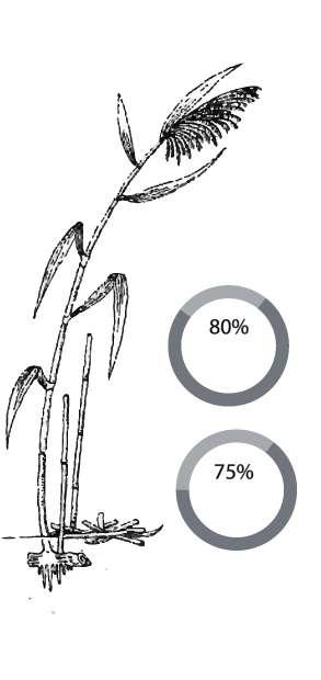
The reed cutter cuts the reeds slicing through the stems just above ground level. Traditionally reeds were cut with a hook or scythe.
2. BUNDLING AND DRESSING THE REED
The bundle is raked to clear out t plant debris and then loosely tied with twine.
3.KNOCKING UP
A loose bundle is taken and the base is repeatedly knocked onto a piece of wood. This process lines up the base of the reads and helps to create a tight bundle ready for thatching.

4. STACKING
The bundles are tightly stacked in a long reed stack and covered with tarpaulin ready to be taken away for thatching
PHENOMENOLOGICAL QUALITIES
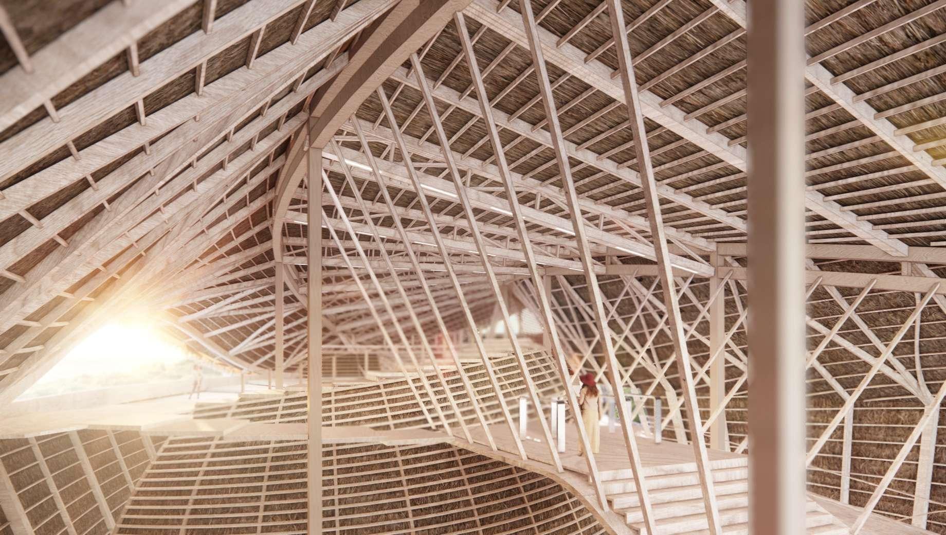
Spatial qualities of thatch informed by the roof depth and substructure condition creates opportunity for atmospheric architectural qualities to create a spatial encounter through an impact on the human senses.- an area of focus within the design intent

Less carbon Emitted in Extraction Cheaper to Produce
“Compared
to concrete
1 2 3 4 RAW MATERIAL
TRADITIONAL SUBSTRUCTURAL SYSTEMS

POST AND BEAM STRUCTURE
Traditionally supported by timber substructures, thatch fibres are woven around bent nodes following incisions in the surface to guide the fibres and to tie several pieces. Assemblies recognize that the tectonics and structural integrity of wood resides in the alignment of its fibres - The threads act as both the distributional components and the binding components of the arrangement
Detail drawing 1.5
axo 1.10 Support plates Batten Laths Eave Board Covering Tie Beam Top Strap Anchoring Post Decking Insulation Board Covering Insulation Base Strap
A TOOL OF RESISTANCE
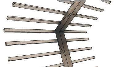
THE JOINT Exploded


PARAMETRIC FORM FINDING


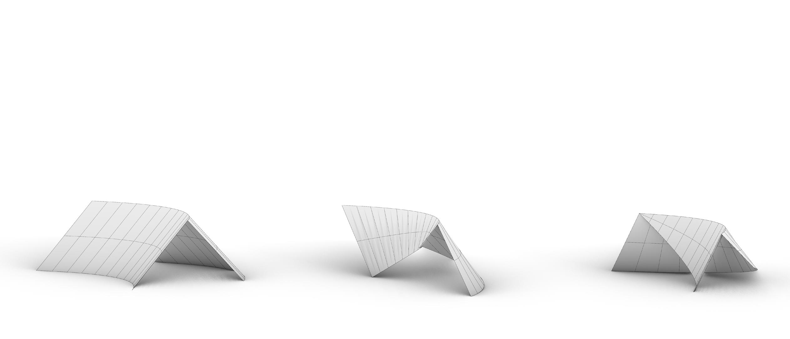
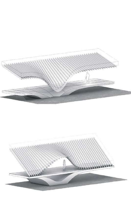
Initial structural logic of posts and beams informed by a grasshopper script enabling hyperbolic paraboloid arrangements allowing for organic forms with orthogonal elementsretaining the essence of original post and beam structures.

VERNACULAR ABSTRACTION
SPATIAL EXPERIMENTS
Experimenting with the articulation of a curved primary structural system of Glulam beams. Whilst retaining linear elements beneath the woven thatch roof surface to retain the essence of traditional post and beam thatching systems.
Small Diameter Timber
Water Reed cultures Stacked Timer Elements
Water Reed Insulation Packing
PERMACULTURE SYSTEM
Concept for a closed system tested whereby the dunescape which can facilitate the growth of water reed as thatching elements is utilised. Assembly harnesses different characteristics of water reed at each level.
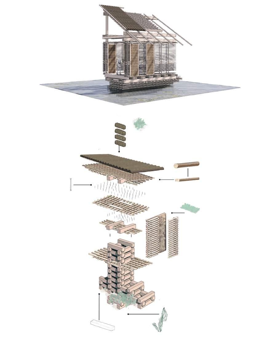 Metal Shear Pins
Water Reed bails in hose nets
Sawn Logs
CLOSED SYSTEM
SUB STRUCTURAL SYSTEM
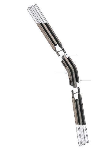


Rudimentary studies depict structural assemblies of supporting substructure as an extension of tested permaculture system facilitating water reed cultures at the base.
 Facade Cladding
Roof thatching
Reed culture system
Scarf Joint
Laminated Veneer Lumber
Glue laminated Lumber
TECTONIC ASSEMBLY
ROOF AS SPATIAL AND STRUCTURAL ELEMENT
Geometric arrangement of substructure brings elements into a single system –- study demonstrates how orientation and combination of structural members used in first study create different spatial opportunities with minimal structural intervention internally.
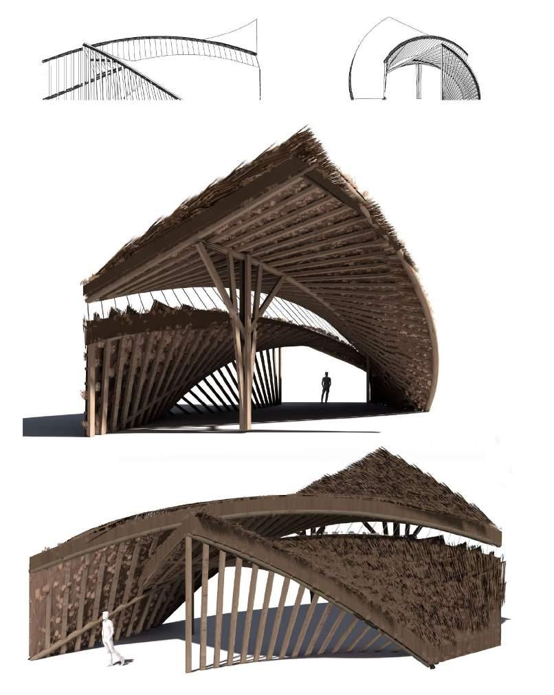
Hyperbolic Assembly
1. Roof size calculated based on programmatic requirements , 45 degree angle applied as the absolute minimum pitch tolerable for a natural thatch roof
2. Roof line extended below ground inorder to accomodate subterranean train line, retaining sy em a s in compression to retain the basement forces
3. Concave massing re onds to the topography and viewpoints of the site, creating a reaching ge ure towards the ocean We and potential for an inner courtyard Ea
4. Roof line optimised to minimise damage to thatching by rong we erly winds, whil creating a dialogue with the landscape

5. Openings considered in relation to the microclimate, inorder to reach a zero-energy level through predominantly passive means
5. Li ed corned indicates entrance ecific to ation served by a drop o area for taxis, cars and buses, segregating foo all between the two programs,
ROOF GENESIS
Grid Optimisation
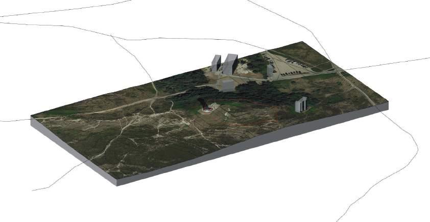
Building site segmented in accordance with different functional requirements of planned building programme
Longitudinal Program Division
Dual forum and infrastructural building programmatically divided

Height Distribution Building responds to site by centrally lifting toward sea view and dipping toward road access on East side
Additional Hyper Rail Entrance Station entrance channels footfall and can be accessed by those approaching via existing footpaths
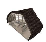
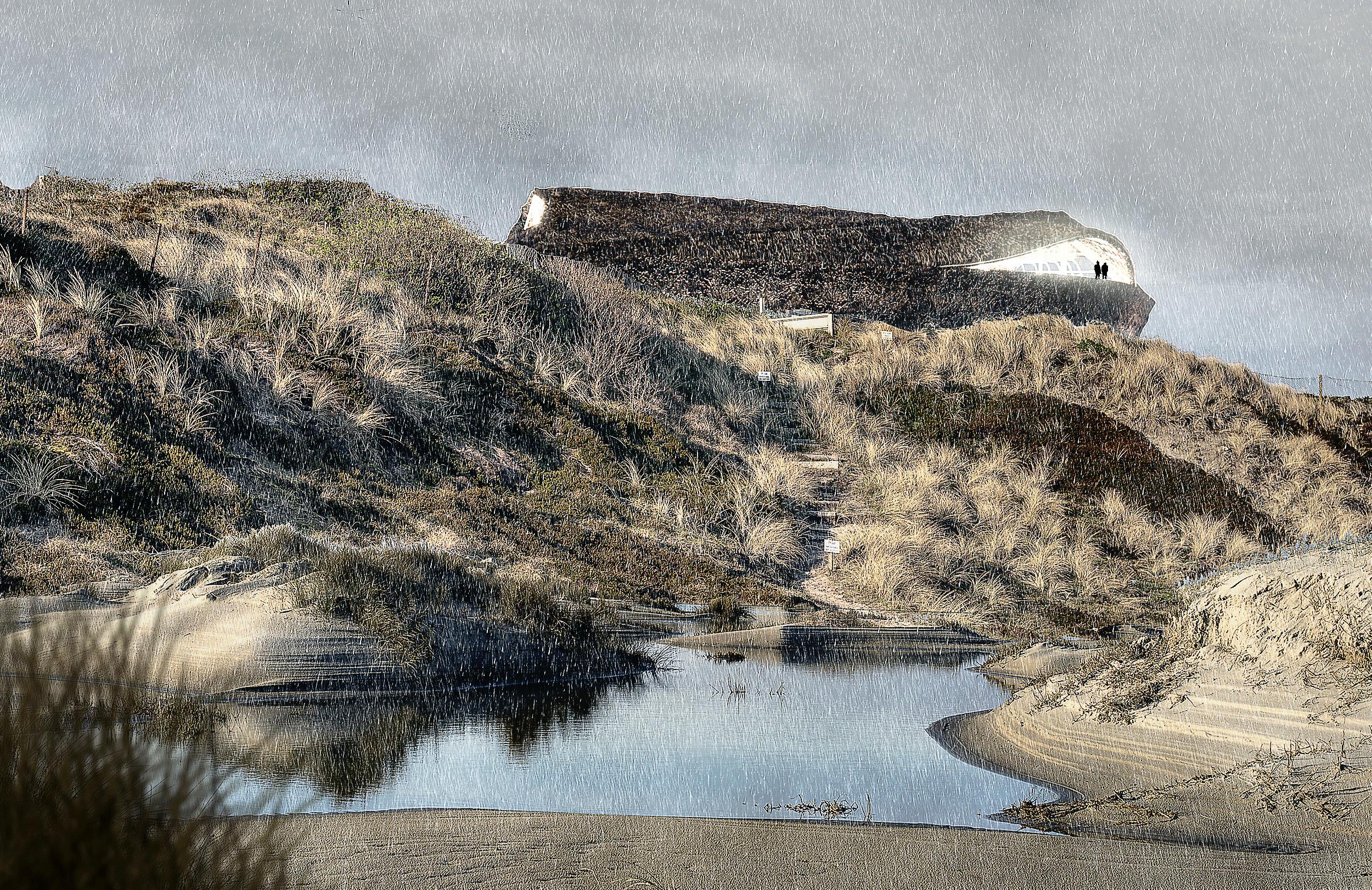
Thatch Roof and Glulam substructure Enables the station to create a dialogue with the dun escape emerging from the landscape, spatial emphasis placed roof as structural element
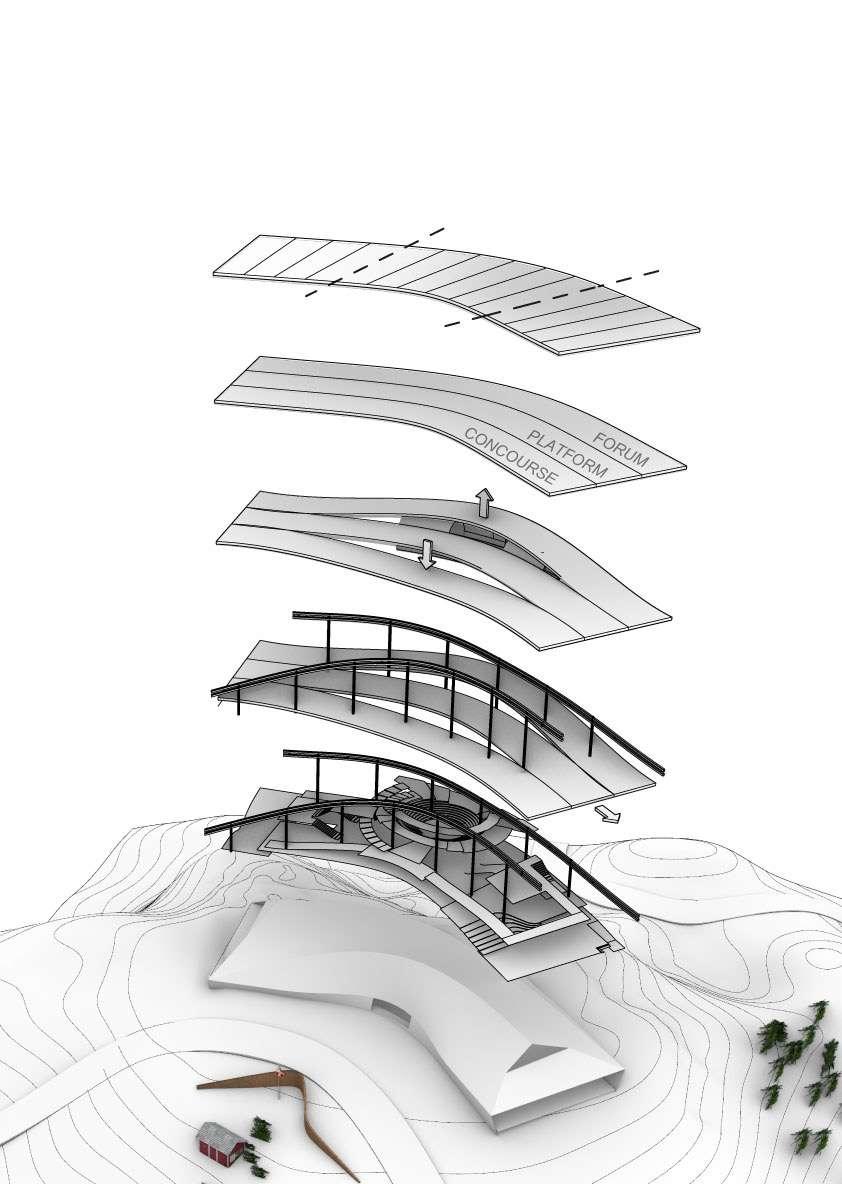
PROJECT BUILD UP
TIMBER STRUCTURAL PORTAL FRAMES CONCRETE RETAINING WALL VERTICAL PRIMARY GLULAM SUPPORTS
is minimized. The archititectural expres-
gives the facade a di erent dimension
SIGNIFICANCE OF THE ROOF
Key investigation of the design is the degree to Which thatch can become an overriding spatial and architectural component of the building, thus the envelope comprises thatch on all surfaces direction a giving it a dimensional quality, compared to traditional structures

ENVELOPE
OPTIONS
STRUCTURAL STRATEGY
FUNCTION DIAGRAM DESIGN DEVELOPMENT
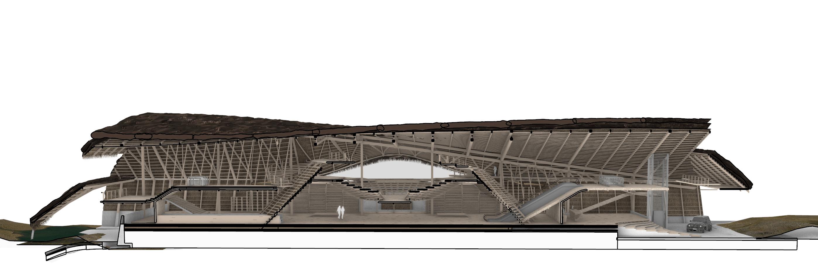
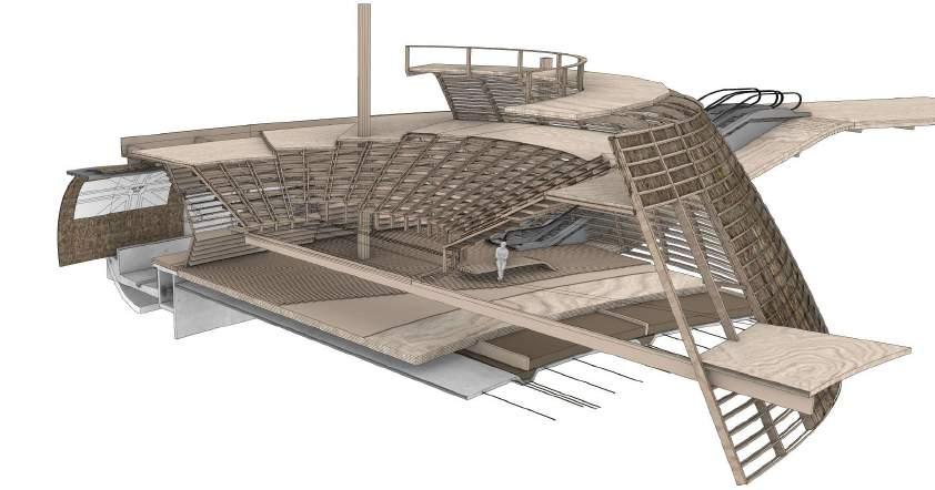
Two programmatic wings converge with a central auditorium and sunken station at half levels with smaller quarter floors between. With a form informed by environmental and programmatic circumstances two main wings host both the concourse and circulation for the multipurpose heart of the scheme.-
FUNCTION DIAGRAM Public Entrance Open passenger lobby Concourse Auditorium Station Entrance Reception Forum discussion Participatory (30 Station Pla Public li to mezzanine level (R+1) and ation pla orm (R-1) Drop o area for bus, taxis and cares (400 (30 m ) 2 (30 (400
PRODUCTIVE LANDSCAPE REED STORAGE AUDITORIIUM VIEWING PLATFORM

VEHICULAR DROP OFF STATION PLATFORMS AUDITORIIUM INFORMATION POINT CONCOURSE Mezzanine level auditorium viewing Public fun ions Sta fun ions ublic Entrance Landscape Viewing terrace Atrium (30 m ) 2 Auditorium 2 Reception Phytopurification basin Reed Storage & Water Filtration discussion ace Participatory entrance 2 (30 m) Pla orm WC Facilities (50 m ) 2 (30 m) 2 (20 m ) 2 (90 m ) 2 (25 m) 2 m) 2 m) 2 m) 2
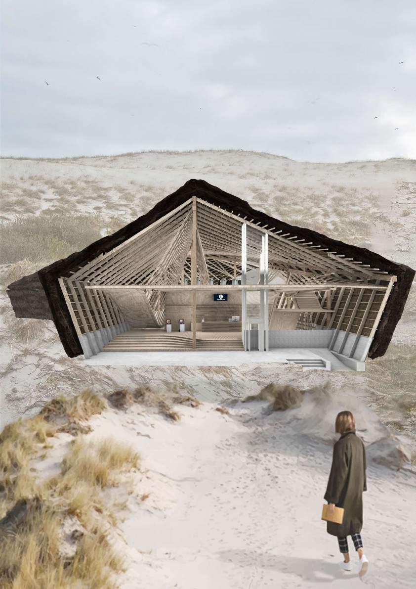
MECHANICAL COMPONENTS
The inclusion of an escalator and lift assists in the efficient and inclusive navigation of the build

CIRCULATION STRATEGY

1: 35 0 20M 60M 80M 0M SI TEPL AN

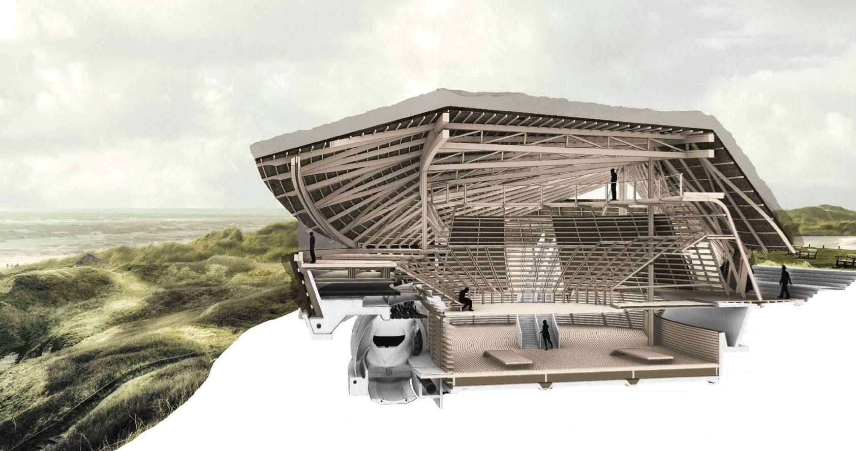
PERSPECTIVE SHORT SECTION Edge Condition


VIEW FROM CONCOURSE Ruled Surface

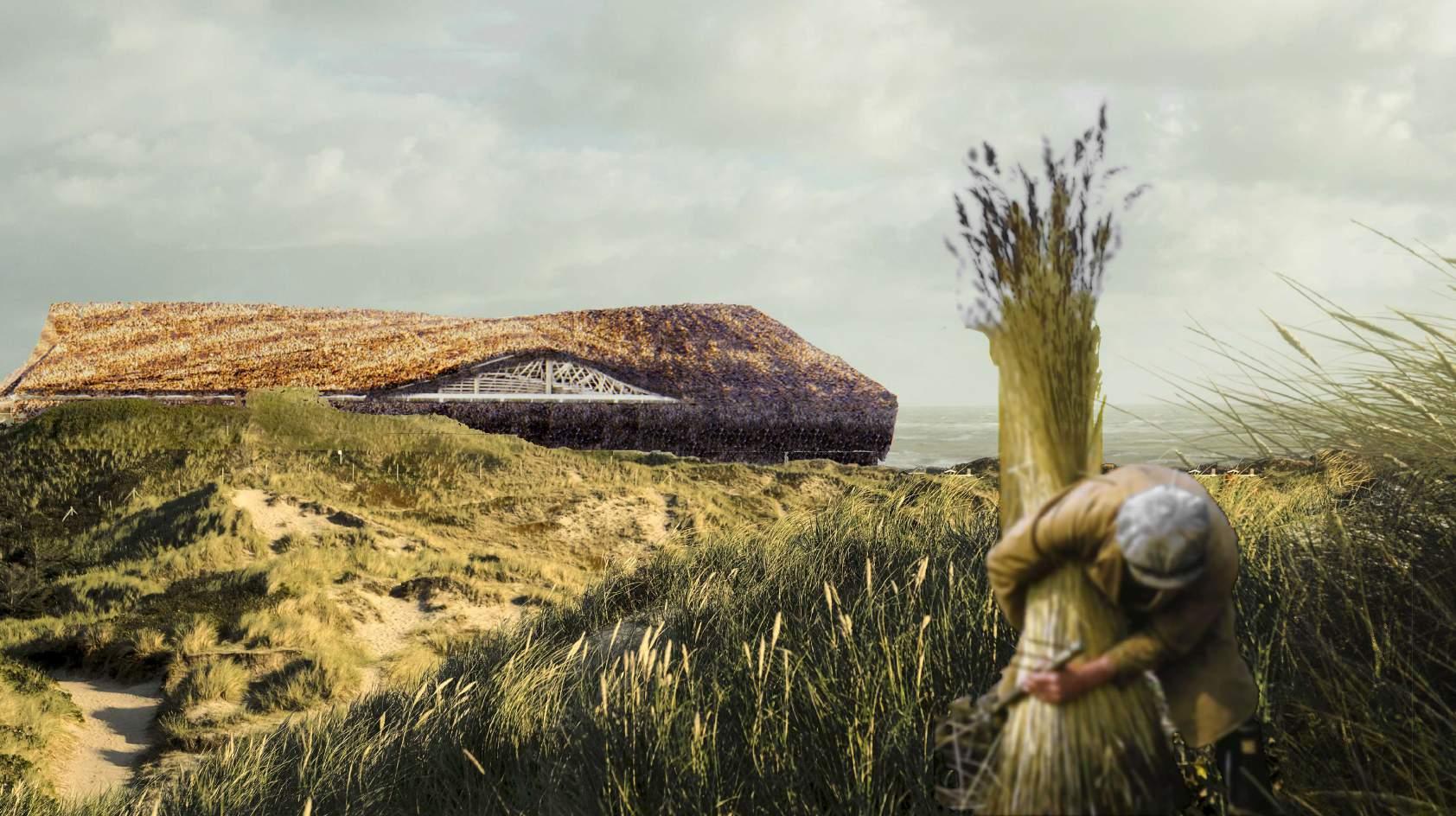
FRONT ELEVATION Thatch Renaissance

ENGINEERED TIMBER FABRICATION

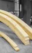


Glulam Straight Glulam Single Curved Glulam Double Curved Glulam
(a) Longitudinal axis. (b) Radial axis. (c)
Tangential axis.
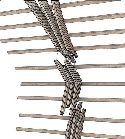
GLULAM NODE DETAIL
The three orthotropic axes of wood. Single -curved Lower curvature Double -curved Higher curvature Single -curved Higher curvature Double -curved Lower curvature
boards), double-curved with low curvature (large square pieces oflumber), single-curved with high curvature (thin, wide planks), double-curved with curved glulam elements: smaller curvatures resul�n smaller lamella
Structural glued laminated timber (glulam) is an engineered, stress-rated product that consists of two or more layers of lumber (i.e., laminations) glued together with the grain running lengthwise, with a high degree of smellable flexibility thus making it suitable as the structural component within the author
The material orientation in (left to right) glulam, CLT, CLT with a dominant direction, CLT with non-perpendicular layers
The different types of glulam blanks (solid blank line) for diffeent curved elements (dashed line); straight, single curved and double curved Bending result in different edge lengths, meaning that lamella lengths need to be compensated during fabrication
NORTH SEGMENT
DE TAIL DESIGN
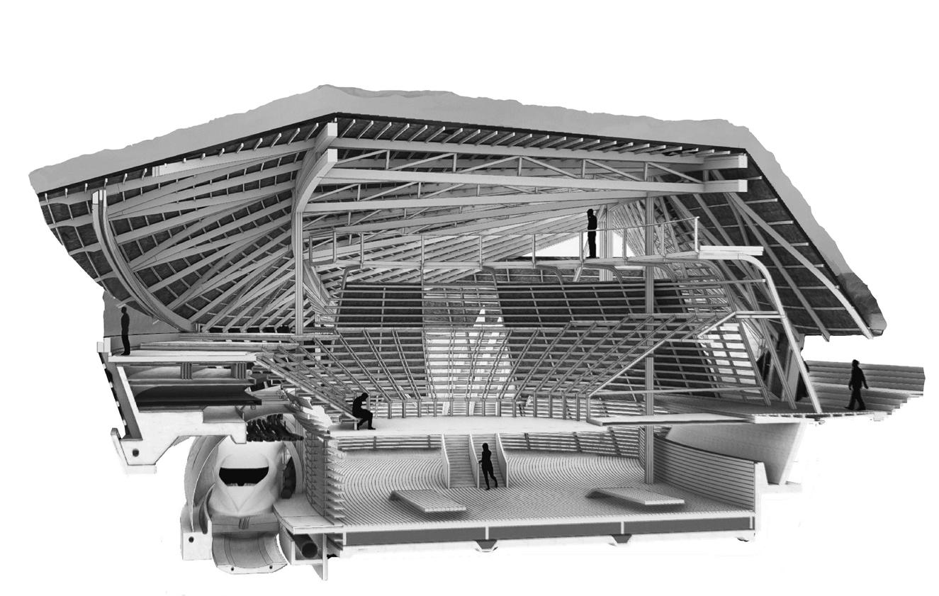
Functional inter-relationships between the di erent components that composes itself as part of the system mechanics- the façade creates an awareness of the inseparable relationship between facades and building. The thatch envelope is interwoven with every aspect of the building design and cannot be considered separately from the roof – Tertiary Substructure informs internal ow of circulation through suspention via the ridge beams,
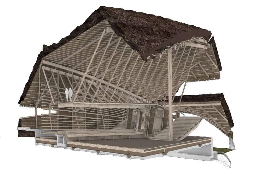
STRUCTURAL DESIGN
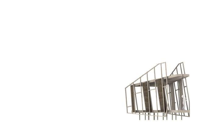
1 2 3. 4. 7 6. 8 10 11 12 13 14 15 16. 1 7
5.
8. Concrete Water Passage
9. Insulated Concrete Foundation Slab
10. Pine Floor Boards
1. Glulam Double Ridge Beam
2. Primary Load Bearing Glulam Beam
3. Linear Roof Truss
4. Tertiary Floor Plate Support Beam
5. Notched Secondary Roof Truss
6. Thatch Battens
7. Five Ply CLT Suspended Floor Deck
15. Phytopuri cation Pool
CIRCULATION
11. Compacted Thatch Insulation
12. Water Reed Thatch Roof Cladding
13. Concrete Retaining Wall
14. Stepped CLT Floor Deck
9 NORTH SEGMENT FRAGMENT
16. Integrated Insulative Thatch Panelling
COLUMN TO COLUMN CONNECTION
INTERIOR OPPORTUNITY - THATCHED ELEMENTS INTERNALLY
COLUMN TO STEEL PLATE BASE CONNECTION
CONSTRUCTION OVERVIEW
Axonemtric diagram depicts relationship between interior members. Tertiary support beams support clt floor plates, suspended from a ridge beam which supports the primary load of the structure.
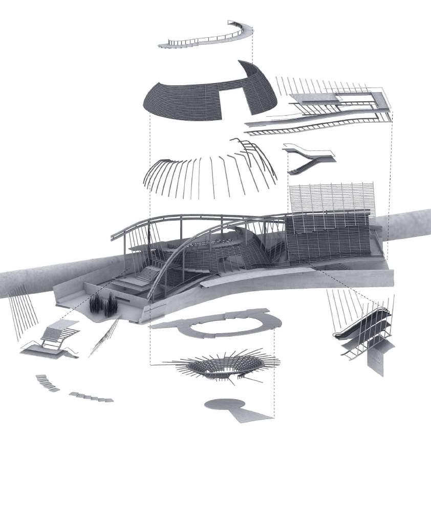
Primary strucuture
Secondary Structure

Tertiray Structure
Thatch Battens
DUAL ACCESS ATRIUM
CENTRAL SUNKEN AUDITORIUM STATION CONCOURSE


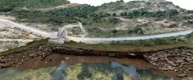


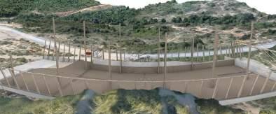
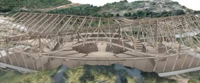
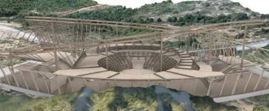
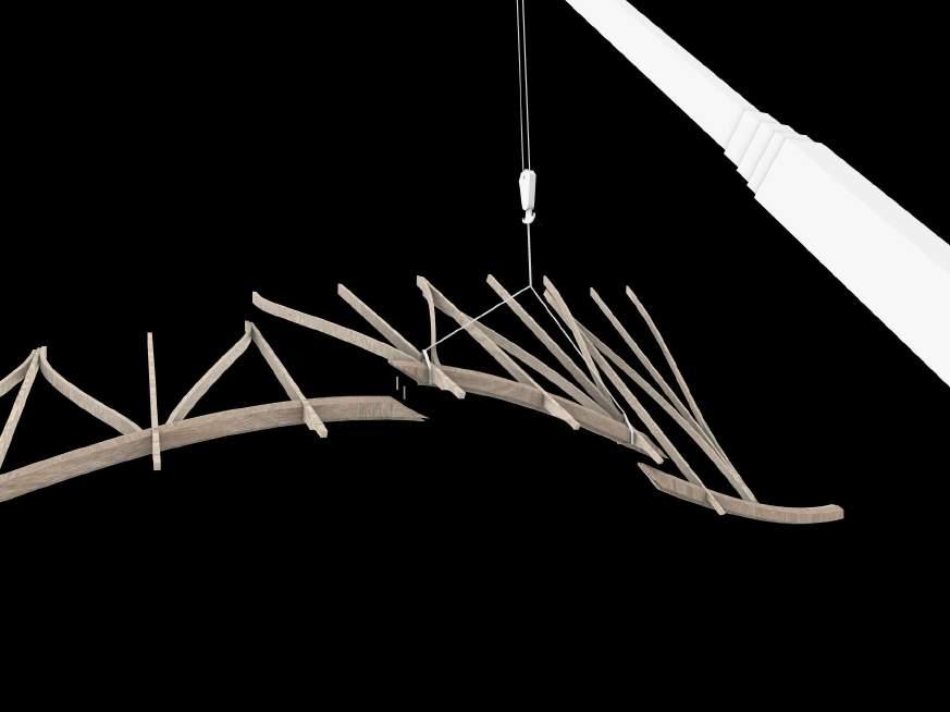 1. Site Excavation - Baseline site includes rock to be blasted and conjoins with tunnelled portion.
2. Foundation pour and recast concrete panel placement
3. Primary vertical glulam beams positioned with adjacent face beam supporting posts
4. Floor girders, ridge beam and adjacent truss supports, ridge beam positioned
5. Floor, stairs and auditorium build out. Thatch battens postioned on lower portion of envelope
6. Envelope secondary beams and trusees, thatch battens positioned on raised portions of envelope.
CONSTRUCTION SEQUENCE
5.
The A.P. Moller - Maersk Group


Facilitating global containerised trade Maersk group is the world’s largest container shipping company and together with our container terminals and logistics businesses we handle a large share of the world’s containerised trade

NET ZERO CARBON

Because of their composition, large glulam members can be manufactured from a variety of smaller trees harvested from second-growth forests and plantations on site. Timber and thatch requires no chemicals to grow, can be harvested by hand or using traditional farm machinery, requires no mechanical processing and therefore has low embodied energy and can be fixed using hand tools. At the end of its life, it can be composted and returned to the land.

1. Maersk Line is the Group’s largest business unit in terms of revenue and the world’s leading container shipping company. Maersk Line is a customer-focused leader in reliable and transport. MAE R SK L IN E
1 Maersk Line operates a vessels. Fleet capacity is ~2.6m TEU (a 20 foot long container). Svitzer Is a global market leader within towage, salvage and emergency vessels. Maersk Supply Serviceshore and associated industries. APM TERMINALS DAMCO AIR FREIGHT 3 APM Terminals operates a global terminal network in 68 countries. in the world. Damco is one of the world’s leading p ers of freight forwarding and supply chain management services. Damco operates more than 93 countries worldwide. Maersk Container Industry Is a manufacturer of dry containers, reefer containers and refrigeration systems. CONSTRUCTION PHASING AND RESOURCING
CONSTRUCTION SITE
STATION COMPONENT
INFRASTRUCTURE STRUCTURAL DESIGN
1. LVL Pannelled Acoustic Barriers
2. Concrete Tunnel Segment


3. Water Reed Thatch Cladding
4. Integrated Insulative Thatch Panelling
5. CLT Floor Decking
6. Integrated Tunnel Drainage System


7. Concealed MEP
8. MDF Soundproofing Ledge
9. Insulated Concrete Foundation Slab
10. Rail Gauge
rovid chain ates in 1 2 3.
7 6. 8 9 10 5.
4.
TECTONIC EXPERIENCE OF STATION
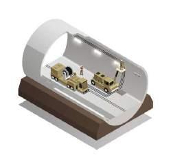
EXCAVATION PROCESS
1. Minimal ground disturbances,
3. Higher advance rates
MECHANISED TUNNELLING
2. Minimal support requirements
Tr uss str ucture
A truss structure is chosen as the structural principle, since it can utilize the whole height of the building for carr ying the spans where

AUDITORIOM
Graphic statics
SOCIAL FLEXIBLE SPACE
analogue and digital tools are used First a simple truss is investigated using graphic statics to settle where there will be compression and tension, and where the highest stresses will be Generally it can be said that the largest forces will be in the top and bottom chords towards the middle of the span. Compression in the top and tension in the bottom respectively
divided by 400. With a length of 64.4m this equals 0.161m. One can though discuss if it
structural members have not been optimized. All trusses are with pinned connections.
STRUCTURAL DESIGN
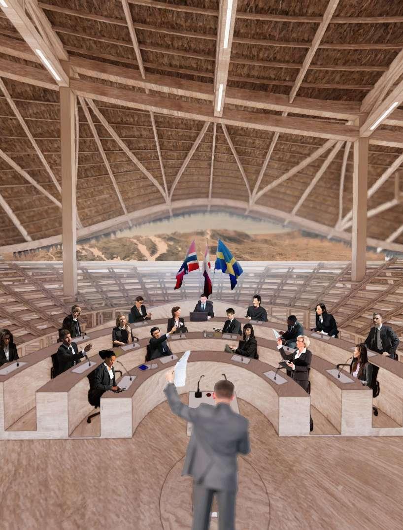
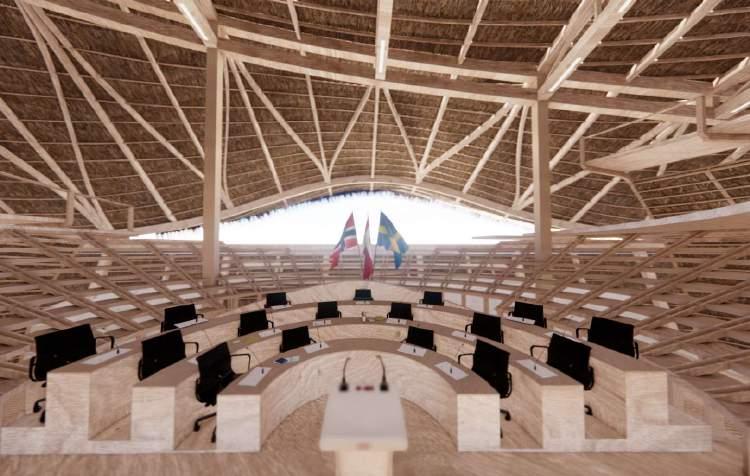
which allows di erent con gurations. In addition to primary function of facilitating meetings between the governing bodies of the countries involved in the union, at any other time it serves a civic function posing as a facility for the land management group and visiting ecologists, a forum for discussions on coastal land management, consolidating and organising cooperatives at city scale, protecting social and ecological capital, diversifying income and creating job opportunities within the eco-tourism sector and beyond.
The great exibility characterizes above all the space of the
truss is a basic ‘Howe truss ’ like the one used for the graphic statics example Aesthetically the many diagonal members are taking up too much space, and making the truss seem too solid, not in line with the concept of a transparent facade
Option 5: Here the intersections are moved down, so the diagonal members meet at the they hit the bottom chord An advantage with this combination is that the beams holding the slab can also act together with the bottom chord to distribute the tension forces in the tension forces in this version is almost half of spatial qualities as well
DETAIL DESIGN
Truss development
Trusses provide opportunity to mount acoustic mineral bibres boards which work work to increase the reach of speakers within the auditorium but also a programmatic advantage.
In the later development digital tools are used to generate quick variations of the truss, and the results are held up against manual calculations.
Since the payload is the dominating load on the structure, for the sake of simplicity these examples are tested with a linearly distributed load, equivalent to 5kN/m2 of exhibition area carried by the truss on the exterior side of the building. In the examples calculated in Karamba for Grasshopper the gravity on the construction is also part of the load scheme. To better be able to compare the results the same material and cross section is used in all these examples.
Option 2: Second variation substitutes the diagonal web members with wire crosses, to create a more transparent facade, but still the vertical members are too dominant.
Option 3: Here the gap between the members are increased to be per 10deg of the circle, still
ther and tested thoroughly in relation to its impact on the spatial qualities.
Option 4: A new test seeking to remove the vertical member by using a double intersection warren truss. Here the forces are transferred in the diagonal members, but due to the level changes of the bottom chord the height of the intersection between the web members changes too, which is not aesthetically and technical-
1 2 3. 4. 7 6. 8 9 10 11 12 13 14 5. 15.
8. Three Ply CLT Platform
9. Integrated Auditorium Seating
10. Five Ply CLT Suspended Floor Deck
1. Water Reed Thatch Roof Cladding
2. Longitudinal Notched Glulam Roof Truss
3. Linear Notched Roof Truss
4. Thatch Battens
5. Glulam Double Ridge Beam
6. Linear Notched Secondary Roof Truss
7. Free form Notched Secondary Roof Truss
15. Concrete Floor Slab
11. Glulam Brace Beam
12. Concrete Retaining Wal
13.Reinforced Column Footing
14. Integrated Drainage System
auditorium,
CENTRAL AUDITORIUM FRAGMENT 120
-
974,0 kN Ill. 120a Howe truss
Position
Ill. 120c Graphic statics diagram for the truss above Compression Tension Null
Ill.
120b
of the truss
ly pleasing. It would be preferred if the forces from the slab could be transferred in the intersection and have a more consistent look of the structure along the plane of movement.
Compression Tension
Ill. 121a ‘Howe truss’
Ill. 121b ‘Pratt truss’ with wire crosses instead of diagonal web members
Ill. 121c ‘Pratt truss’ with wire crosses instead of diagonal web members
Ill. 121d ‘Double intersection warren truss’ with the slab resting on the web members
Ill. 121e Variation on a ‘double intersection warren truss’
The connection point of a truss structure with slotted steel plates, steel dowels and bindings.


121
Option 1 Highest Compression [kN]: 974,04 Highest tension [kN]: 992,13 0,082 Option 2 Highest Compression [kN]: 1041,54 Highest tension [kN]: 1033,89 0,073 Option 3 Highest Compression [kN]: 1436,72 Highest tension [kN]: 1394,38 0,100 Option 4 Highest Compression [kN]: 1453,79 Highest tension [kN]: 1412,15 0,124 Option 5 Highest Compression [kN]: 1346,58 Highest tension [kN]: 742,41 0,083
STRUCTURAL TRUSS ITERATIVE STUDY


FRAGMENTS
ENVELOPE
STRUCTURAL CONDITIONS
Fragments depict different instances of the inter dependant relationship between the envelope and intenal substructure. (1) Two clt level, reinforced ply to mitigate reverberation from hyper train tunnel immediately below, (2) Single level decking with idouble height ceiling and ncllined concrete retained basement level (3)Suspended walkway utilising primary constructive aspect of the arrangement
STRUCTURAL DESIGN
1. Primary Load Bearing Glulam Beam
2. Water Reed Thatch Roof Cladding
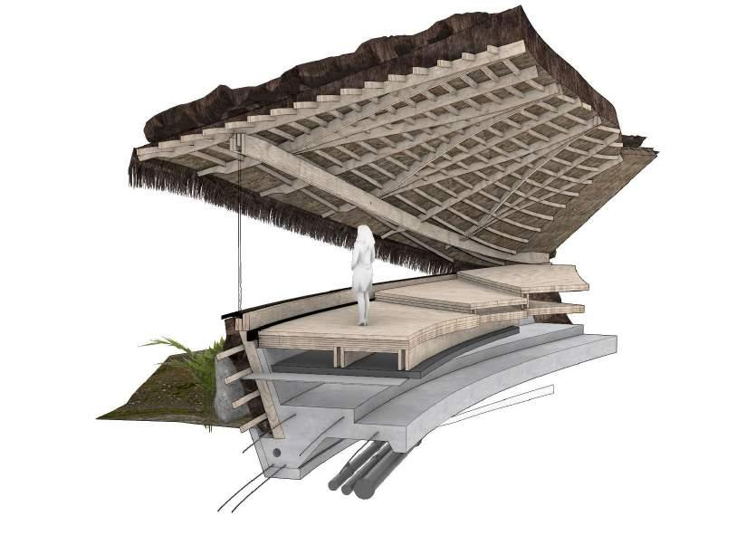
3. Glulam Double Ridge Beam
4. Secondary Free Form Roof Truess

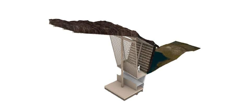
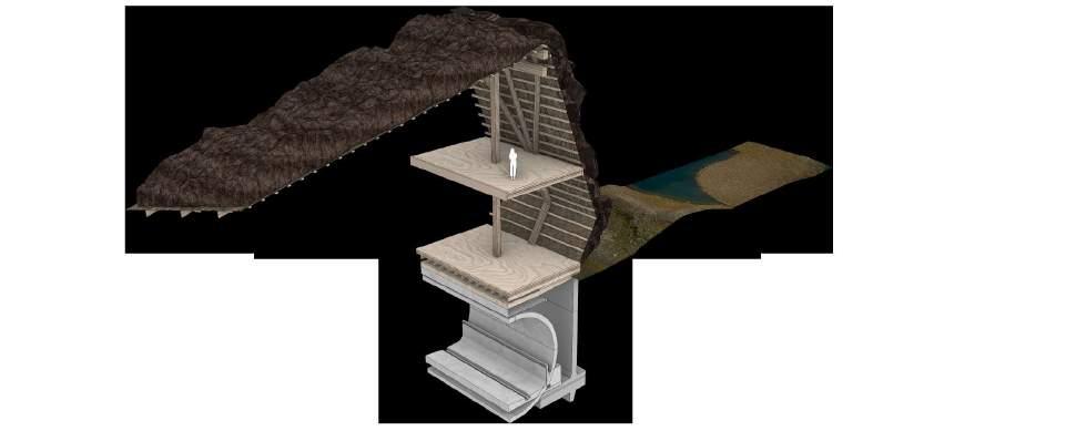
5. Secondary Roof Truss
6. Concrete Retaining Wall
7. Concrete Foundation Slab
8. Concrete Tunnell Segment
9. Railway Gauge
10. Pine Decking
11. Insulated Concrete Foundation Slab
12. Tertiary Floor Plate Support Beam
13. Five Ply CLT Suspended Floor Deck
1. Glulam Double Ridge Beam
2. Primary Load Bearing Glulam Beam
3. Linear Roof Truss
4. Tertiary Floor Plate Support Beam
5. Secondary Roof Truss
6. Thatch Battens
7. 5 Ply CLT Suspended Floor Deck
8. Concrete Water Passage
9. Insulated Concrete Foundation Slab
10. Floor Boards
11. Compacted Thatch Insulation
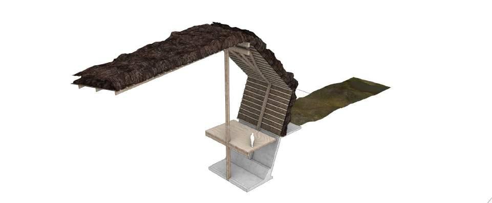
1 2 4. 8 10 11 12 13 5. 3. 1 2 3. 4. 5. 1 2 3. 4. 5. 6. 6. 6. 7 9 7
THATCH ENEVELOPE SUBSTRUCTURAL CONDITIONS


1 2
3.
4.
7
6.
10 11 12 . 13 14 15
8. 9.
5.
8. Five Ply CLT Suspended Floor Deck
9. Vertical Glulam Thatch Battens
10. Notched Floor Deck Support Beams
1. Water Reed Thatch Roof Cladding
2. Glulam Thatch Battens
3. Notched Secondary Roof Truss
4. Overhanging Eaves
5. Glulam Header Beam
6. Low Emissivity Glazing
7. Integrated Base Beam 15. Integrated Drainage System
STRUCTURAL DESIGN
11. Vibration Damping Board
12. Concrete Footing
WINDOW FRAGMENT STRUCTURAL DETAIL
13. Steel Rebar 14. MEP
ACOUSTIC

LVL pannelled shuttered barriers act to mitigate sound distubanc e from passing trains. Noise reduction % estimates are based upon the measured reduction in decibels based upon the university testing, with 10 decibels reductions, equated to a 50% reduction in perceived noise.


drama Elementar y Classrooms Recorsing & Broadcasting studios Cinema Intimate Small Theaters Lecture and Conference Rooms Churches High School Auditoriums Cathedrals Multipurpose Auditoriums Semiclassical concer ts & chorus Secular Chours Musicals Comedies Aperesstes Dance and Rock bands Recital chambre Music Operas Lituricical (orchestra, chorus & organ) Symphonic 0,2 0,4 0,6 0,8 1,0 1,2 1,4 1,6 1,8 2,0 2,2 2,4 2,6 ACOUSTIC STRATEGY
PANELLING
5 PLY CLT floor plates reduce reverberation from passing trains. Isolatig the noise from activities internally
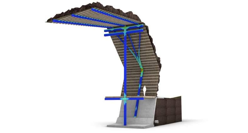
Finite element analysis (FEA) demonstrates stress distribution across structural members simulating the behaviour of a part or assembly under given conditions Being the load of the thatch in this instance. Results show articulation of elements results in an evenly distributeed load which is structurally integral. notches considerably reduce the load-carrying capacity of beams, because of the stress concentra-tions at the abrupt change of cross-section together with low strengths and brittle failure mecha-nisms of timber in tension perpendicular to grain and in shear. Micro-notches are a valid replacement for conventional notches for TCC slabs, providing several ad-vantages. The composite action of micro-notches can be assumed rigid, no additional screws or dowels, are needed, and the timber cross-section is less compromised than with conventional notch-es. The principle of operation of micro-notches is similar to that of glued connections, were the mi-cro-notches have a lower, still su_cient strength, but operate without any adhesive.



STRESS ANALYSIS
INTERNAL VIEW Spatial Tectonic

OBSERVATIONS

The graphs show the ouptur of excessive temperatures and comfort termperatures of the initial analysis. As seen the platform and auditorium does not fulfull the requirements. In addition, the entrance is later lowered due to atmospheric reasons. In this context there is created an overhang on the outerface of the builfing to accomodate potential overheating issues. Even though the hours above-analysis shows excessive tempoeratures the gneral comfort temperatures are almost within building category 2 medium
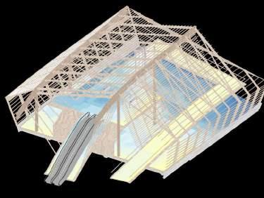

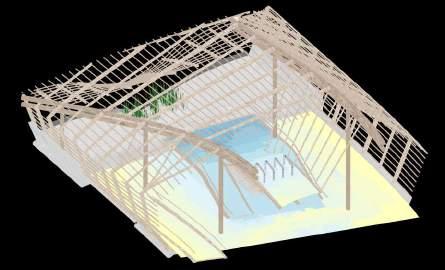

4684 7466 4325 8832 3994 1252 4413 42 0% ry II 40% 90% III80% 100% CAFE OR OFFIUICME ENTROFAFNICCE E COMFORT TEMPERATURES 61 117 58 28 32 36 61 29 11 12 0 80 100 120 140 >26 >27 6854 4684 7466 H O U R S A BO V E 4325 8832 1860 3994 1252 0% 4413 42 10% 20% 30% 50% 40% 60% 70% 80% 90% 100% AUDITORIUM ENTRANCE Category I Cat COMFORT TEMPERATURES egory II Cat y III egor Above 61 117 58 28 32 36 61 29 11 12 0 20 40 60 80 100 120 140 CONCOURSE PLATFORM AUDITORIUM DROP OFF ENTRANCE DROP OFF PLATFORM CONCOURSE
THERMAL COMFORT
Water Source Heat Pumps - Recover the latent thermal energy absorbed by the wetlands. Water is pumped into the system where the latent heat is used to compress a refrigerant. The refrigerant then transfers heat into the distribution system, powering the building.


OBSERVATIONS
The following analysis of the energy consumption shows thaat that the energy consumption in general increases due to the changes of the design. Especially seen when the substitution of windows are made, since bettwe insulated windows cause less pssive solar heating, eventually causing a higher heating demand
. 117 94 72 61 58 59 61 51 39 35 33 0 24 20 40 60 80 100 120 140 EXHIBITION EXHIBITION SEUXNHSIBHIATIDOINNG EXHIBITION g- EXHIBITION EXHIBITION Int gXrHaItBeIdTBIOliNnds EXHIBITION FewEeXrHIWBiInTIOdoNws FewEeXrHIWBiInTdoIONws 82000 82500 83000 83500 84000 84500 85000 85500 EXHIBITION S G EXHIBITION EXHIBITION g- EXHIBITION EEXXH T I EBRIITOIO R SEHXATEDRINIOG EXHIBITION FEWEEXRHIWB I IT NDIOONWS Q H E A T + HE A T CO IL 117 94 E N E R G Y C O N S U M P T I O N 72 61 58 59 61 51 39 35 33 24 0 20 40 60 80 100 120 140 EEXNHEIRB I GTYI OCNO N I TSEURMAPT I T I OONN S AUDITORIUM STATION SUNSHADING Integrated Blinds Curtains > Fewer Windows 26 >27 H O U R S A B O V E 81500 AUDITORIUM I T E R A T I O N S Emissive Glazing AUDITORIUM STATION SUNSHADING Integrated Blinds Curtains Fewer Windows Emissive Glazing SH ENERGY STRATEGY
PHYTO - PURIFICATION
Where aquatic and non-aquatic plants feed on elements that are in the water, yielding oxygen, and thus regenerating healthy and clean water. These techniques can help us keeping water clean and purifying it naturally.
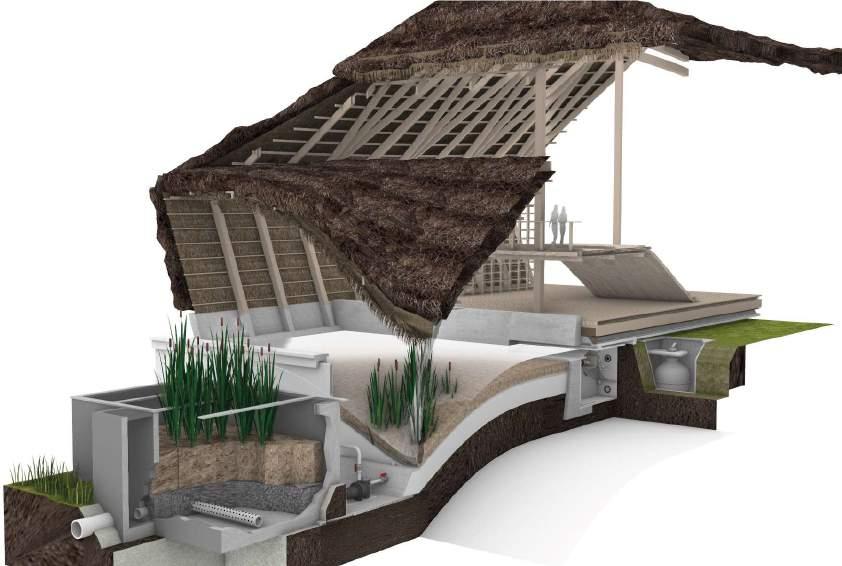

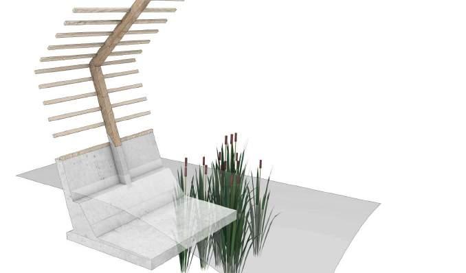
PHYTOPURIFICATION POOL
PASSIVE VENTILATION
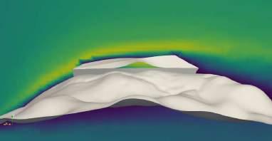

Wind-driven cross ventilation occurs via ventilation openings on opposite sides of the enclosed space. Figure 1 shows a schematic of cross ventilation serving a multi-room building, referred t as global cross ventilation. The building floor plan depth in the direction of the ventilation flow must be limited to effectively remove heat and pollutants from the space. Figure 2 demonstrates an instance of stack ventilation conversely.
AERODYNAMIC FORM
By orienting the building’s front face towards the South - the form follows the prevailing direction against the strong southern wind, - not only does the roofs shape contribute in sheltering from the wind, but it also has been formed to limit points of weakness where thatch could be ripped off by prevailing breezes.

0.0 21.6 5.0 10.0 15.0 20.0 U [m/s] Magnitude .2 5 m > 11 m 11 0 m SE SW WSW ESE ENE NNE NNW WNW Ill. 2.20 Wind technical
FIGURE 1
FIGURE 2
The inclusion of day lighting in designing, through design tools, results in improved daylight, and therefore reduces visual discomfort. From energy point of view, the main objective of windows is to provide "usable" daylight to the interior of offices, allowing the electric lighting to be replaced by natural light and reducing the cost of electric load. The determination of daylight-related performance indicators of illuminance, and daylight factor were identified by software (VELUX).

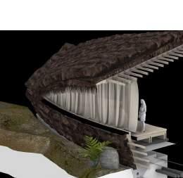
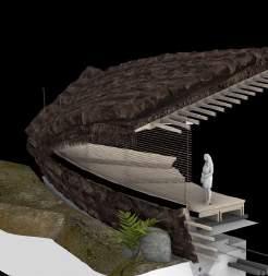
DAYLIGHT ANALYSIS - AUDITORIUM been to
Blinds
Curtains
Emissive Glazing
REQUIREMENTS
The part of the program that needs more sunshine is along the East facade (Auditorium, Station and ticket office ) and the concourse. . The commercial functions face the open porch southwards therefore although not affected by direct light they can benefit of a generous diffused light. The large glazed window of the auditorium is facing south t given its heavy use
WINTER SOLSTICE DAYLIGHT DISTUTION
DECEMBER 21ST
SUMMER SOLSTICE DAYLIGHT DISTRIBTION
JUNE 21ST
ACCESS TO LIGHT

In the development of the project, two strategies have been analysed using the Ladybug plugin for GH (sunlight hours) to assess the potential of bringing natural light down into the station.

0
12
24
HOURS
HOURS
HOURS
DAYLIGHT ANALYSIS - GLOBAL
ACCESS TO LIGHT

In the development of the project, two strategies have been analysed using the Ladybug plugin for GH (sunlight hours) to assess the potential of bringing natural light down into the station.


ill. 2. 16 | Distribution according to type of precipitation over a year Jan Feb Mar Apr May Jun Jul Aug Moderate Rain light rain (11%) Jan 3 78% Apr 1 66% May 23 57% Jul 2 64 % Oct 1 76% Dec 31 78% light snow (12%) moderate snow (12%) moderate rain (57%) Sep Oct Nov Dec 90% 80% 70% 60% 50% 40% 30% 20% 10% 0% average Precipitation | 17 2 ill Jan 92 66 75 50 68 73 91 115 156 148 136 110 110 Feb Mar Apr May Jun Jul Aug Sep Oct Nov Dec Annual Avarage Percipetation (mm) THATCH MAINTENANCE FRESH THATCH +5 YEARS +10 YEARS +15 YEARS
EMERGENY SERVICE ACCESSIBILTY
SPRINKLER PLANS
In recent years there have been many advances in domestic sprinkler systems. The life safety advantages and the extra property protection can be considerable. Sprinkler heads should always be placed so that the sprays overlap—the distance one head throws should reach the head of the next sprinkler. This is called headto-head coverage, and sprinklers should be placed equidistantly in each zone to achieve it.
Hose
Ladder

Alarm Emergency Phone
Access Point

CHAR LAYER
An alternative solution provides a design allowance for sacrificial layers of char—a method already utilized in traditional large-scale wooden construction with post and beam structures. Wood burns; however, it does so at a slow rate of around one millimetre per minute. Further, the charred layer formed from the initial burning acts as a fire-resistant coating. In other words, in the event of a fire, an exposed piece of thick, solid wood—used as is—can slow the overall combustion rate, allowing time for evacuation.
SITE CONTEXT 1
1250
:
Emergency services situated 0.2 Km from site allowing for a rapid response
FIRE & LIFE SAFETY
Raw material availabilty of timber indicated on the plan contributing to the buildings sustainable life cycle. The building adopts regenerative methods of construction throughout the construction process and lifecycle
Nor th Sea Base P or t
The Por t of Esbjerg in the Danish par t power in Europe.
has been the primary base por t for all oil and gas activities of the Nor th Sea. The Por t of Esbjerg is the leading por t for wind
Connection s to Europ e
Right from the beginning, trade with England has been an impor tant business several liner shipping companies connect the via a comprehensive route network. area for the Por t of Esbjerg, and today Por t of Esbjerg with the whole of Europe
Esbjerg O shore wind farms nvolving Port of Esbjerg Oi elds serviced from Esbjerg Danish territory ebrugAntwerp Pur eet Ze ge Portbury Stavanger NeAberdeen wcastle Immingham Bergen Southampton Alexandria Ashdod Izmir Setubal Limassol Pireus Salerno Palermo Savona Bilbao Gothe Wallhamn nburg Trondheim Amsterdam Drammen Cork Esbjerg
45 % 10 % Impor ts Logs 6 mn m 3 Expor ts Logs 1 mn m 3 sub** Sawlogs Pulpwood Gross felling 90 mn m 3 sk Net felling 75 mn m 3 sub** 35 mn m 3 sub** 35 mn m 3 sub** Bioenergy Sawmills 55 % 5 mn m 3 sub (bark) Wood products 47 % After drying chips 14 % Bioenergy Shavings + dry Wood chips 31 % paper Heat Recovered Pulp and paper Ene rg y rec ov ered Shrinkage etc 8 % trimming allowance Electricity and heat 45 % Pulp and paper mills (bark) Bioenergy CHP plants 5KM
10KM

THE DANISH STATE GUARANTEE MODEL FOR INFRASTRUCTURE INVESTMENT
In the Danish state guarantee model, individual private limited companies responsible for the delivery of the project are firstly set up by the Danish (Nordiskløkke Danmark A/S) and Norwegian states (Nordisksløyfe Norge AS). The states will then act as financial guarantors for loan agreements (through the Danish National Bank and Norges Bank), which are bought on international credit markets, where Norway and Denmark’s triple A credit rating is leveraged as guarantors to borrow money with more favourable interest rates. Extra capital can then be injected by the states as and when needed but the risk of the project is shifted from the state budgets and welfare systems.
Loans taken out throughout the duration of the delivery of the project are then repaid through revenue from user tolls paid to the public state-owned operations and maintenance contractor (DSB nordicloop).
Main Characteristics of the SGM
- Paid for by users
- State guarantee on all loans
- Low financing cost
- Organised through a private company entity
- Full-state ownership of the company entity
- Full-state control and insight SERVICES CONTRACT WORKS CONTRACT
PROJECT ARCHITECTS
Apointed to operate within the consortium for the duration of the design and build phase
ENGINEERS
Informing structural, mechanical, environmental and geological aspects of the project
CONSULTANT SPECIALISTS
Thatch, tunnelling and excavation specialist shall be conferred with among others
MULTIPLE PARTY PARTNERSHIP
Multiple parties would be deeply involved in this project and diverse expertise are requred in delivering the project to its top outcome quality. Therefore, partnering as the procurement method is decided for the project.
Diverse requirement in the project requires different partiesto act as partners and be involved through out every stage, in oder to achive positive result, successful partenring is based on mutual trust , commitment to shared goals and open communications among all involved parties,
SUPPLIERS Contracted to provide materials as part of the delivery of a built asset.
WORKS SUB CONTRACTORS
Thatch, tunnelling and excavation specialist shall be conferred with among others

ON-SITE ARCHITECTS
negotiations with contracts and dealing with and resolving any problems that may occur.
START OF CONSTRUC TI ON
CONTRACTOR Company?
OPERATIONS AND MAINTENACNE
Plant
DOCUMENTATION Document Management and Record Keeping O&M SCHEDULING Preventative and Corrective Maintenance Scheduling CONTRACT Operation and Maintenance Contract Management WARRANTY
Equipment Repair and Maintenance Warranty Management with Vendors INSURANCE Plant Insurance Coverage And Management Assist REGULATIONS Central and State Government Regulatory Compliance Assist
BUILD CONTRACTOR RAPID TRANSIT SYSTEM USER FEES CONSTRUCTION CONTRACT OPERATIONDS AND MAINTENANCE CONTRACT THE CLIENT THE CLIENT THE CLIENT NORWEGIAN STATE CLIENT RERESENTATIVE Joint State Owned Consortium DANISH STATE SWEDISH STATE SHARE CAPITAL AND STATE GURANTEE STATE OWNED A/S STATE OWNED A/S STATE OWNED A/S
DESIGN AND
parties. C1 C2 C3 T1 T2 T3 Q1 Q2 Q3 0 1 2 3 4 5 Construction Priorities
INFORMATION DESK & TICKET OFFICE


1: 35 0 20M 60M 80M 0M SI TEPL AN General Arrangement s
1: 35 0 20M 60M 80M 0M LEVEL 00 General Arrangement s
1: 35 0 20M 60M 80M 0M LEVEL -0.5 General Arrangement s
1: 200 10M 40M 60M 0M SECTION B:B General Arrangement s
All work produced by Unit 14
Unit book design by Charlie Harriswww.bartlett.ucl.ac.uk/architecture
Copyright 2021
The Bartlett School of Architecture, UCL All rights reserved.

No part of this publication may be reproduced or transmited in any form or by any means, electronic or mechanical, including photocopy, recording or any information storage and retreival system without permission in writing from the publisher.

-

@unit14_ucl UNIT


 Cover design by Charlie Harris



 Metal Shear Pins
Water Reed bails in hose nets
Sawn Logs


 Facade Cladding
Roof thatching
Reed culture system
Scarf Joint
Laminated Veneer Lumber
Glue laminated Lumber


 1. Site Excavation - Baseline site includes rock to be blasted and conjoins with tunnelled portion.
2. Foundation pour and recast concrete panel placement
3. Primary vertical glulam beams positioned with adjacent face beam supporting posts
4. Floor girders, ridge beam and adjacent truss supports, ridge beam positioned
5. Floor, stairs and auditorium build out. Thatch battens postioned on lower portion of envelope
6. Envelope secondary beams and trusees, thatch battens positioned on raised portions of envelope.


