
SPORTS
AYAKA SATOYEAR 5 @unit14_ucl UNIT Y5 AS
THE MIND
STADIUM
All work produced by Unit 14
Cover design by Charlie Harris
www.bartlett.ucl.ac.uk/architecture
Copyright 2021
The Bartlett School of Architecture, UCL All rights reserved.
No part of this publication may be reproduced or transmitted in any form or by any means, electronic or mechanical, including photocopy, recording or any information storage and retrieval system without permission in writing from the publisher.


-
@unit14_ucl
-
ayakasato.96@gmail.com @ayakaa.s
FIGURES PLAY
THE MIND SPORTS STADIUM
Tokyo, Japan
The project explores the structural principles of traditional Japanese timber constructions for application in designing a large-scale mind sports stadium in Tokyo, Japan. The country is facing a demographic crisis, with forecasts suggesting that half of the population will be over retirement age by 2050. To address the issue of a hyper-aged society, a novel entertainment typology is proposed. This typology integrates the popular Japanese mind sport of Shogi, which is renowned for its intellectual challenge and is widely played by an aged demographic.
The proposal for robot figures seeks to provide a unique entertainment experience that combines technology with traditional cultural entertainment. Sited in Odaiba, a high-tech entertainment zone within Tokyo Bay, the project explores a robotics mind sports stadium, which will create a new horizon for the ageing society within an
urban context. The overall structural system is developed by integrating traditional Japanese timber constructions of flexible structures and the reciprocal stacking method. The system functions as a component that can be combined to form a more extensive system for a substantial roof on a large scale. The roof opening considers its connection with the surrounding urban environment, linking the urban and waterfront areas. The movement of figures establishes the spatial arrangement, and an atrium promenade is introduced to respond to players of varying skill levels. In addition to providing a new kind of entertainment, the proposal will pave the way for human and AI coexistence inside built environments.
AYAKA SATO YEAR 5
Y5 AS
Ayaka Sato 21137024
BARC0175
Advanced Architectural Design II 2023/2024
Unit 14
Unit Tutors
Dirk Krolikowski
Jakub Klaska
FIGURES PLAY.
THE MIND SPORTS STADIUM
Future entertainment typology in Tokyo, Japan
The project explores the structural principles of traditional Japanese timber constructions for application in designing a large-scale mind sports stadium in Tokyo, Japan. The country is facing a demographic crisis, with forecasts suggesting that half of the population will be over retirement age by 2050. To address the issue of a hyper-aged society, a novel entertainment typology is proposed. This typology integrates the popular Japanese mind sport of Shogi, which is renowned for its intellectual challenge and is widely played by an aged demographic. The proposal for robot figures seeks to provide a unique entertainment experience that combines technology with traditional cultural entertainment. Sited in Odaiba, a high-tech entertainment zone within Tokyo Bay, the project explores a robotics mind sports stadium, which will create a new horizon for the ageing society within an urban context.
The overall structural system is developed by integrating traditional Japanese timber constructions of flexible structures and the reciprocal stacking method. The system functions as a component that can be combined to form a more extensive system for a substantial roof on a large scale. The roof opening considers its connection with the surrounding urban environment, linking the urban and waterfront areas. The movement of figures establishes the spatial arrangement, and an atrium promenade is introduced to respond to players of varying skill levels. In addition to providing a new kind of entertainment, the proposal will pave the way for human and AI coexistence inside built environments.
SECTION 01: ARTEFACT RESEARCH
FRAGMENT EXPLORATION III 1.1
ARTEFACT CASE STUDY I - KINTAI BRIDGE
KINTAI BRIDGE - DIFFERENTIAL TIMBER SYSTEM
KINTAI BRIDGE - RECIPROCAL STACKING SYSTEM
KINTAI BRIDGE - ASSEMBLY RESEARCH
ARTEFACT CASE STUDY II - HORYUJI PAGODA
HORYUJI PAGODA - JOINERY AND ASSEMBLY
HORYUJI PAGODA - LOAD TRANSFER MECHANISM
RECIPROCAL STRUCTURE EXPLORATIONS
FRAGMENT EXPLORATION I
FRAGMENT EXPLORATION II
SECTION 02: BRIEF AND CONTEXT
CONTEXTUAL RESEARCH - TOPOGRAPHY OF JAPAN
JAPAN - TRANSPORTATION NETWORK
JAPAN - ECONOMY AND INDUSTRY
JAPAN - POPULATION
PROJECT BRIEF - ENTERTAINMENT INDUSTRY
PROJECT BRIEF - SHOGI (JAPANESE MIND SPORT)
PROJECT BRIEF - ROBOTS INTEGRATION
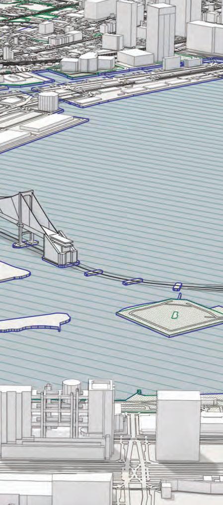
PROJECT SITE - TOKYO BAY
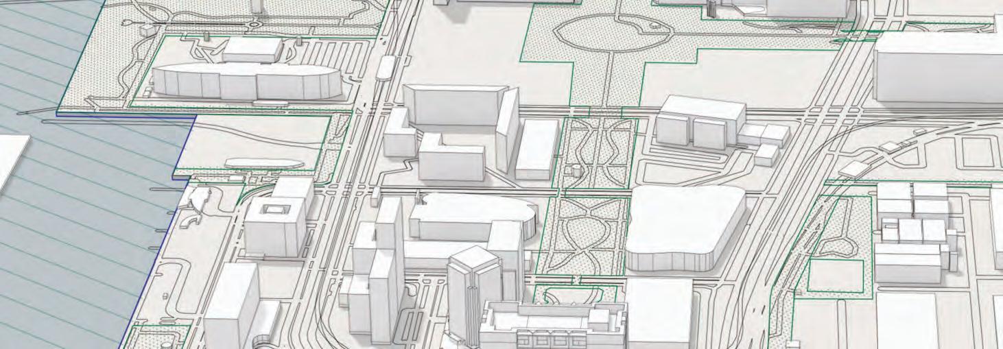
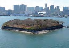
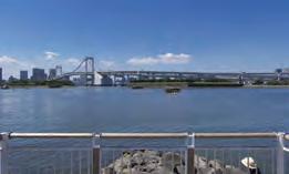
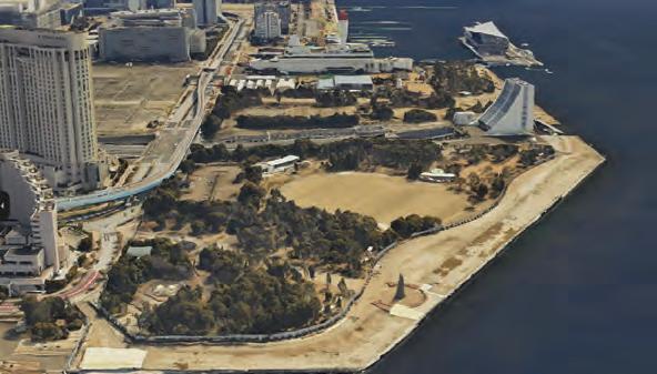
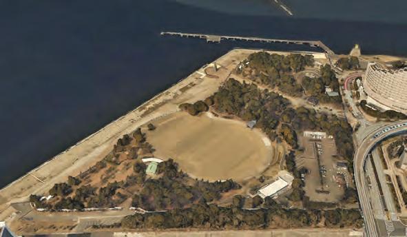
PROJECT SITE - ODAIBA
SITE ANALYSIS
PROGRAMME - ROBOTICS MIND SPORTS STADIUM
SECTION 03: DESIGN DEVELOPMENT
SHOGI MOVEMENT EARLY EXPLORATIONS
FRAGMENT DEVELOPMENT
GLOBAL FORM EXPLORATIONS
GLOBAL FORM DEVELOPMENT
SECTION 04: DETAILED DEVELOPMENT
ROOF STRUCTURE AND ANALYSIS
PRIMARY STRUCTURE
STRUCTURAL COMPONENT I
STRUCTURAL COMPONENT II
PRIMARY STRUCTURAL COMPONENTS
JOINERY AND ASSEMBLY
STRUCTURAL OPTIMISATION
STRUCTURAL AGGREGATION - AXIS I
STRUCTURAL AGGREGATION - AXIS II
VERTICAL CIRCULATION
FRAGMENTS
PREFARICATION AND CONSTRUCTION
SPATIAL TYPOLOGIES
SECTIONAL FRAGMENT
PROJECT KEY LEVELS
SECTION 05: FINAL DRAWINGS & GENERAL ARRANGEMENTS
AERIAL VIEW - GLOBAL SCHEME
EXTERIOR - WATERFRONT ACCESS
EXTERIOR - URBAN SIDE ENTRANCE
INTERIOR - SEA SIDE OBSERVATORY
INTERIOR - CORNER DISPLAY ZONE
INTERIOR - ROBOTICS PLAY
INTERIOR - OBSERVATORY CORNER
INTERIOR - EDUCATIONAL CENTRE
PERSPECTIVE SECTION
SITE PLAN
1.3 1.4 1.5 1.6 1.7 1.8 1.9 1.10 1.11 2.1 2.2 2.3 2.4 2.5 2.6 2.7 2.8 2.9 2.10 2.11 3.1 3.2 3.3 3.4 3.5 4.1 4.2 4.3 4.4 4.5 4.6 4.7 4.8 4.9 4.10 4.11 4.12 4.13 4.14 4.15 5.1 5.2 5.3 5.4
5.6 5.7 5.8 5.9 5.10 5.11 5.12
1.2
5.5
FLOOR
SECTION
PLAN CROSS
3-4 5-6 7-8 9-10 11-12 13-14 15-16 17 18 19-20 21-22 25-26 27 28 29-30 31-32 33-35 36 37-38 39-40 41 42 45-46 47-48 49-50 51-52 53-54 57 58 59-60 61-62 63-64 65-66 67-68 69-72 73-74 75-76 77-78 79 80-82 83-86 87-88 91-92 93-94 95 96 97-98 99-100 101-102 103-104 105-106 107 108 109-110
01
SECTION 1: ARTEFACT RESEARCH
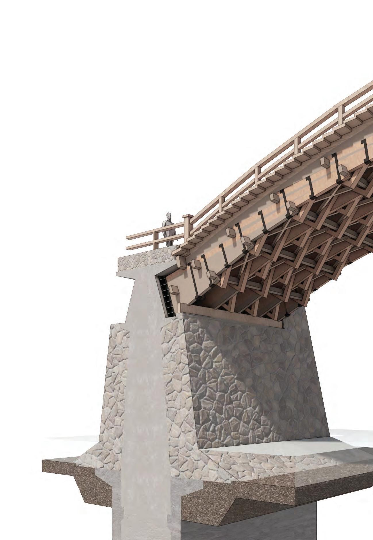
Bridge to pier connection
The bridge piers themselves have a concrete structure on the inside, with the surface being covered in dressed stone for decorative purposes.
3 R= 132.0 15.0 132.0 15.0 5 13.5 1.1 ARTEFACT RESEARCHARTEFACT CASE STUDY I - KINTAI BRIDGE horizontal reaction force is generated at the hinge support points
Hinge
1.5 m thickness stone cladding
arch bridge arch br girder bridge 35.1m 34.8m4.6m4.6m 35.1
Metal Straps
KINTAI ARCH BRIDGE
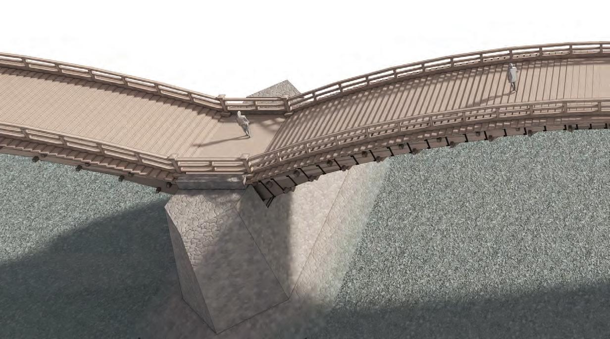
The Kintai Bridge, located in Iwakuni City, Yamaguchi Prefecture, Japan, is an exemplary timber structure known to withstand seismic activity. The structure spans the Nishiki River and was initially constructed in the year 1673. It is the most extensive wooden arch currently in existence.
4 SECTION 1ARTEFACT RESEARCH idge
Girder
Cross Beam
bridge girder bridge 35.1m 1m 34.8m 4.6m4.6m Girder Wedge Ridge Pole 1 2 3 4 (Small Ridge Beam) (Large Ridge Beam) The ridge beam is designed to be longer in order to sustain the arch construction of the bridge, as it experiences a significant compression force.
arch
1st Beam 2nd Wedge Base Beam 1st Hanabari 2nd Hanabari 3rd Hanabari 4th Hanabari 5th Hanabari 6th Hanabari 7th Hanabari 8th Hanabari Side Ridge Beam Ridge Beam 1st Atobari 2nd Atobari 3rd Atobari 4th Atobari 5th Atobari 6th Atobari 7th Atobari8th Atobari Obari Keshobari Futokorobari 3rd Wedge 4th Wedge 5th Wedge 6th Wedge 7th Wedge 8th Wedge 2nd Beam 3rd Beam 4th Beam 5th Beam 6th Beam 7th Beam 8th Beam 9th Beam 10th Beam 11th Beam
Omunagi
Komunagi
Cross
Beam






The Kintai bridge is built of several wood species best suited to each member’s function. Keyaki (Japanese zelkova) is utilised for structural members and members that transfer heavy loads. Matsu (Japanese pine) is employed in other places because of its superior resistance to bending. Because Hinoki cypress is resistant to decay, it is applied in areas exposed to the elements, such as the bridge plate, tread, and railing.
5 37% 38 % 16.1 % 7.3 % 1.4 % 0.2 %
Hinoki Cypress Matsu Pine
Keyaki Zelkova
Hiba False arborvitae Kuri Chestnut Kashi Oak
1.2 ARTEFACT RESEARCHKINTAI BRIDGE - DIFFERENTIAL TIMBER SYSTEM
Hinge arc
h structure
Load-bearing strucure
Fiber direction
Radial direction
Tangential direction
The structure of wood
pith - central cylinder of tree heartwood - the dense inner part of tree trunk spawood - outer part - less durable & lighter color cabium - growing part of the trunk bark - the external covering of wood
3 different planes of section
The properties of wood are explained in three directions.
1. tangential direction (direction tangent to annual rings)
2. radial direction (direction outward from the center)
3. fiber direction (direction toward the trunk)
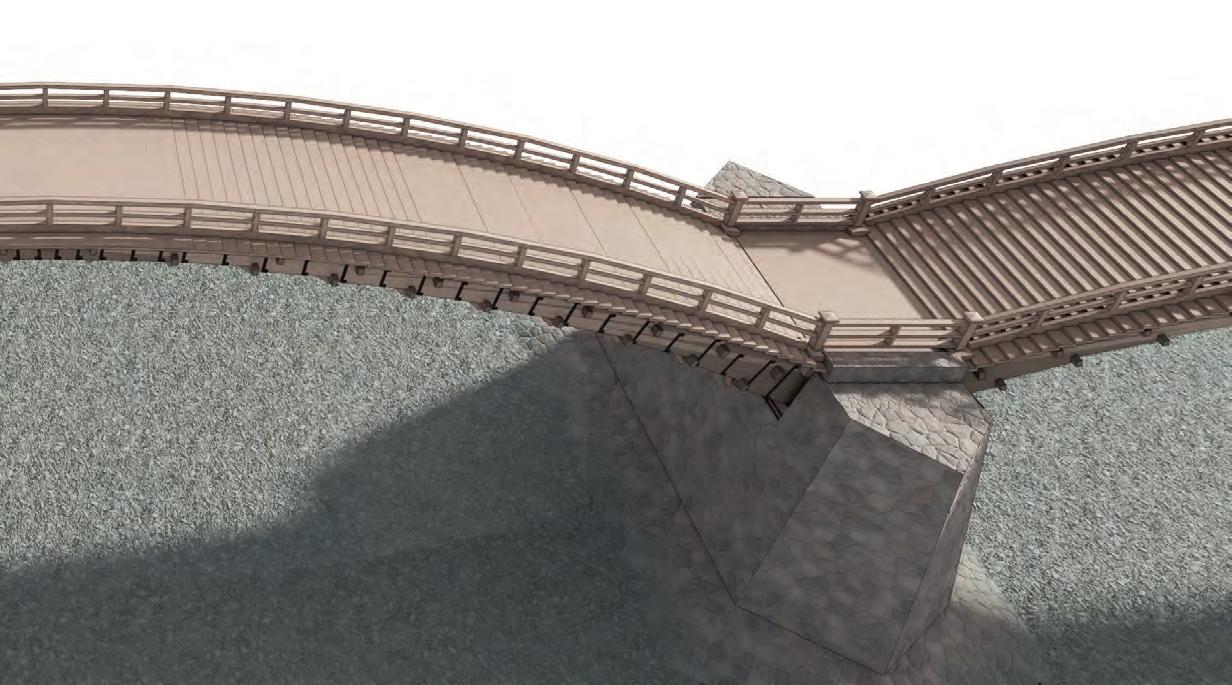
KINTAI ARCH BRIDGE
The wood used must withstand harsh weather conditions, such as wind and rain. Due to the susceptibility of the outer layer of wood, referred to as the ‘sapwood,’ to decay, only the inner part, known as the ‘heartwood,’ was utilised. The use of diverse timber species and carefully selecting wood parts enable the bridge to attain optimal structural and material efficiency.
6 SECTION 1 ARTEFACT RESEARCH
Sapwood Heartwood
Pith Heartwood Bark Cabium Sapwood
Handrail
Bridge plate and tread
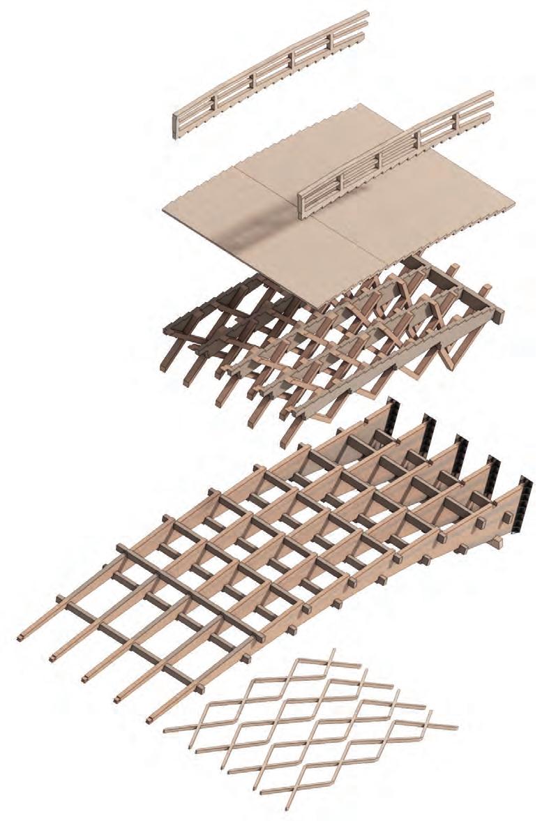
BRIDGE ARCH COMPOSITION
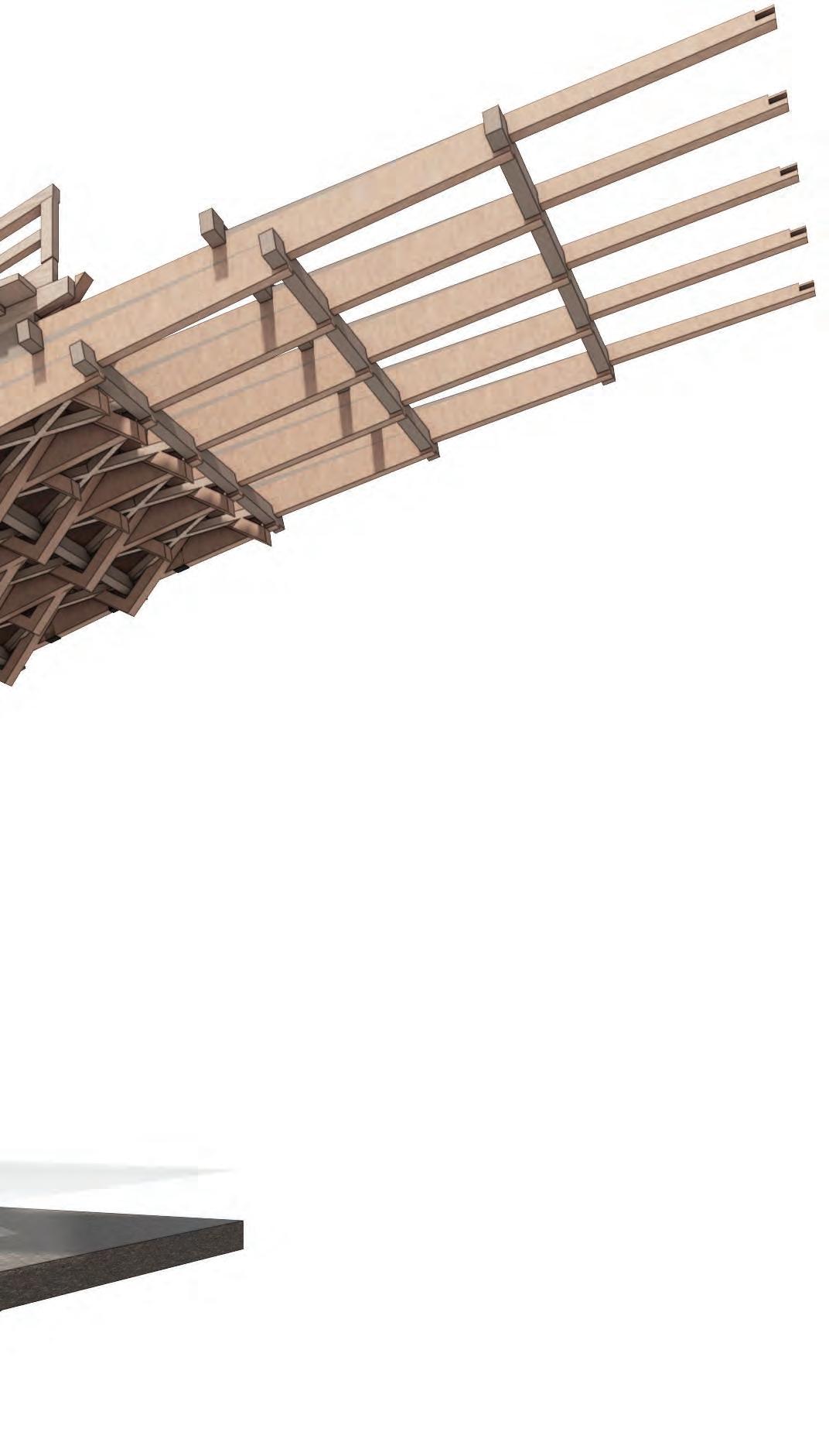
The loads, including the weight of the arch bridge, generate vertical and horizontal reaction forces at the fulcrum. Consequently, the arch is designed in such a way that the axial force dominates while minimising the bending moment on each member. Hence, the slender timber elements (measuring between 6m-8m) are stacked together to form a greater cross-sectional area, mitigating their inherent susceptibility to compression force.
7 1.3 ARTEFACT RESEARCHKINTAI BRIDGE - RECIPROCAL STACKING SYSTEM
Kurabi (diagonal bracing)
Keta (girder)
Hari (cross beam)
Back bracing
Kusabi (wedge)
Heikin-gi (levelling packer)
Bridge plate and tread
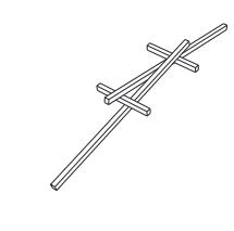
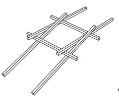
reciprocal relationship
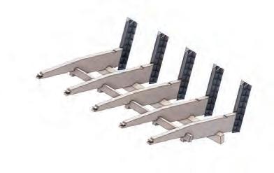
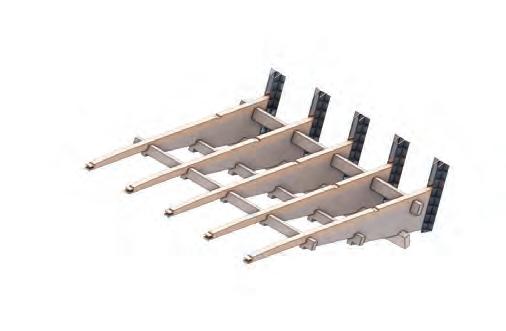
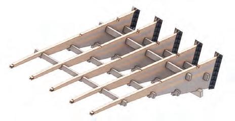
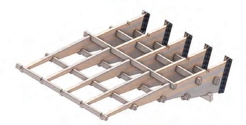
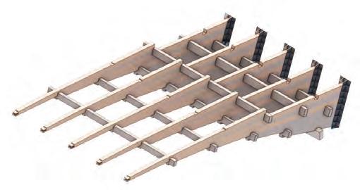
RECIPROCAL CANTILEVERING STACKING
Each member protrudes by about one-third of its length from the girder member directly beneath it. With the formation of this orthogonal lattice structure, a selfstabilising system that can be disassembled and reassembled is formed in creating an arch bridge, establishing a linear reciprocal relationship.
8 SECTION 1 ARTEFACT RESEARCH
Linear
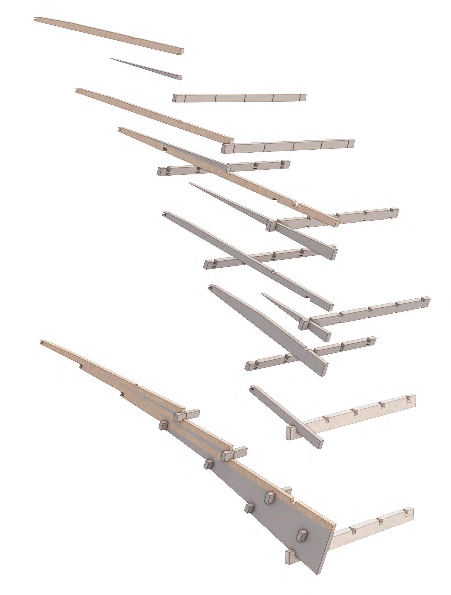
JOINERY SYSTEM
The structure of the Kintai bridge uses only mortise and tenon joinery. One girder member is vertically attached to another girder or wedge while also being perpendicularly connected to the front and rear cross beams. Long dowels are also used for the assembly of vertical components. This configuration induces deformation at multiple locations, where friction reduces the lateral forces caused by earthquakes.
9 1.4 ARTEFACT RESEARCHKINTAI BRIDGE - ASSEMBLY RESEARCH
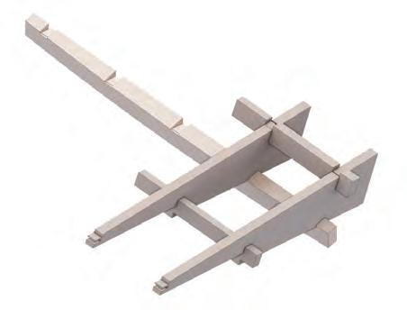
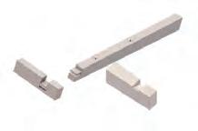
PHYSICAL ASSEMBLY
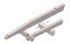
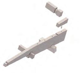
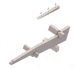
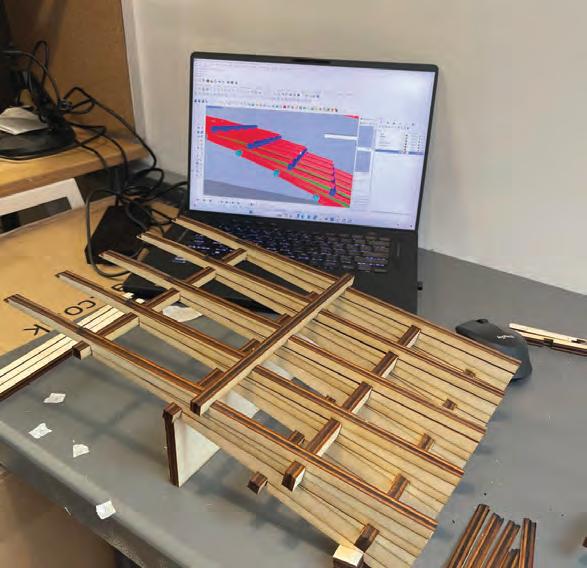
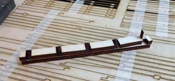
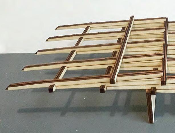
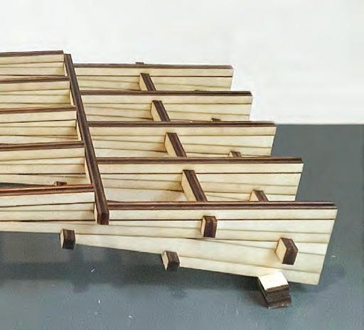
A segment of the Kintai bridge digital model was extracted to conduct further research into the reciprocal relationship of component assembly at a 1:20 size. Throughout this process, it has become clear that the structural relationships of each component are evidently based on the principles of ‘orthogonal reciprocal interactions.’ This arrangement connects the straight girder members at both ends, allowing the endpoints (fulcrums) to move forward simultaneously, creating a continuous connection.
10 SECTION 1ARTEFACT RESEARCH
Assembly of first few girders
The components are laser-cut for physical assembly
Physical model in scale 1:20
Rear cross beam
Front cross beam
Wedge
First girder
Second girder
Girder to cross beam joint mortise and tenon joints
Girder to girder joint dowels connection
Cross beam to girder/wedge joint mortise and tenon joints
Wedge to girder joint dowels connection
Not carrying the weight of the building
Long eave roof
Due to heavy rainfall
Balancing Mechanism


HORYUJI PAGODA: EARTHQUAKE PROOF STRUCTURE
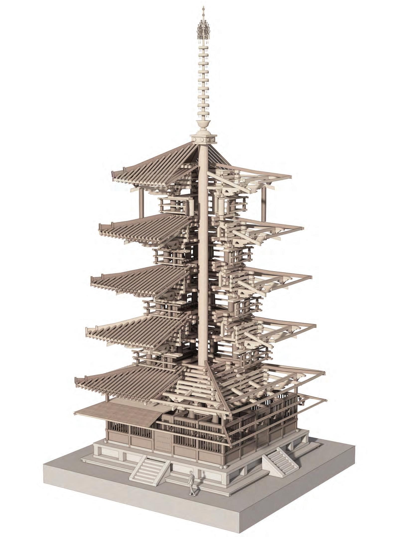
The Horyu-ji Pagoda, commonly referred to as the ‘Five-story Pagoda,’ is a famous example of Japanese architectural architecture and Buddhist creative expression. Built in the early 7th century, this building is one of the oldest remaining wooden structures in the world. The structure has endured 46 earthquakes with a magnitude of 7.0 or more since it was built.
11 1.5 ARTEFACT RESEARCHARTEFACT CASE STUDY II - HORYUJI PAGODA
Central column - Shinbashira
Offset
Gap between the central column and the structures
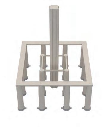
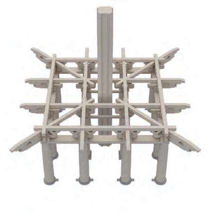
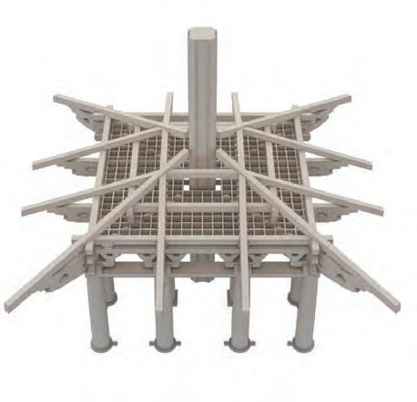
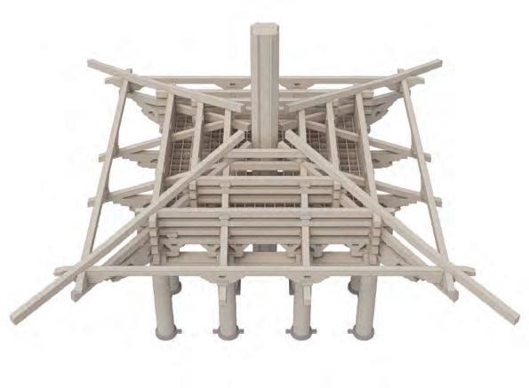
12 SECTION 1ARTEFACT RESEARCH 1 Central column Architrave Dowel Four inner pillar Side pillar Side girder Outer girder Bracket complex Bracket arm (third layer) Angle rafter Bracket arm (first layer) Bracket arm Cloud-shaped bracket Tail rafter Corner tail rafter Bracket arm Short pillar Lattice ceiling 2 3 4 Base Isolation Snake DanceCentral ColumnTuned Mass Damper Slip Joint Slipping Sliding Balancing toy TMD Friction Friction Damper Vibration control devices of the pagoda
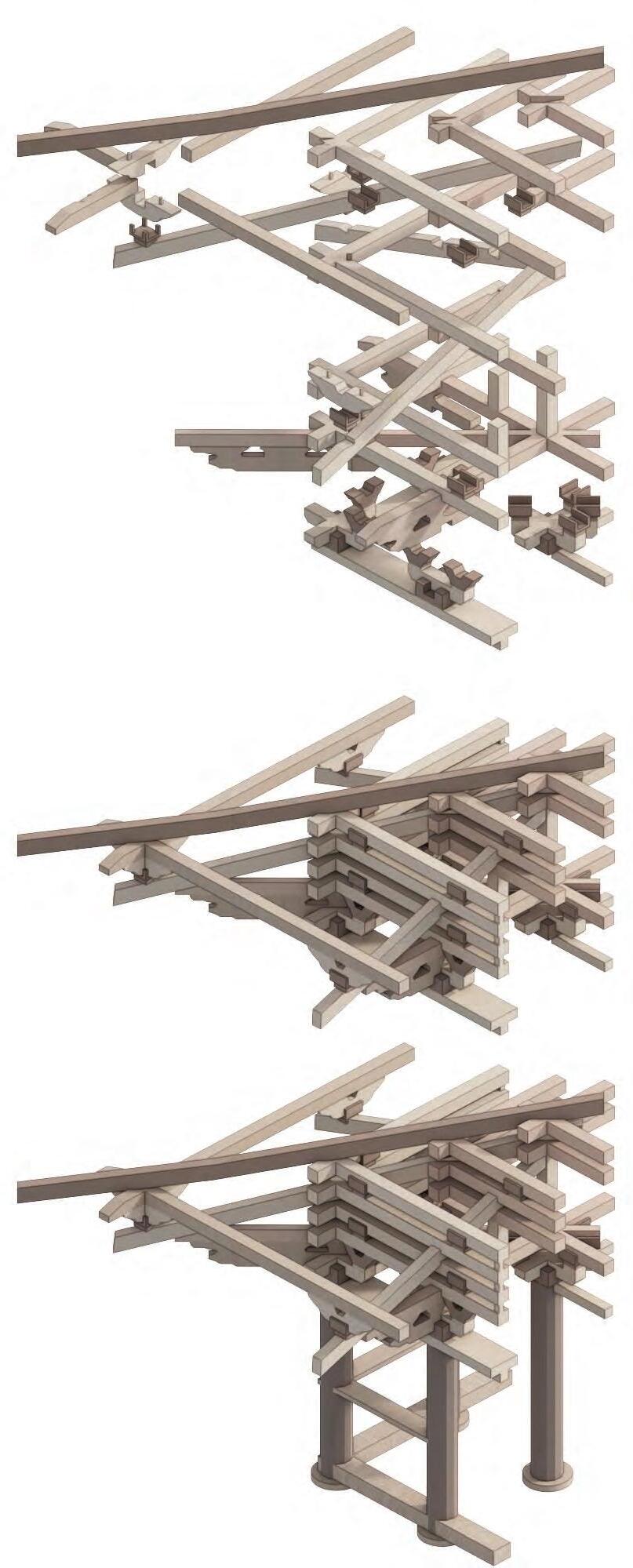
INDEPENDET STACKING
The structure of the Five-storied Pagoda consists of five layers that are stacked independently of each other. Each floor rests only on the pillars of the layer below and the cross beams on the rafters and do not attach to the floor they are placed on. By employing a layered structure, the likelihood of transmitting movement from the lower stories to the upper levels is diminished, even in the event of swaying in the first story during an earthquake.
13 1.6 ARTEFACT RESEARCHHORYUJI PAGODA - JOINERY AND ASSEMBLY
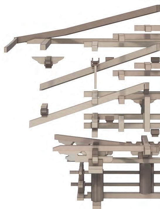
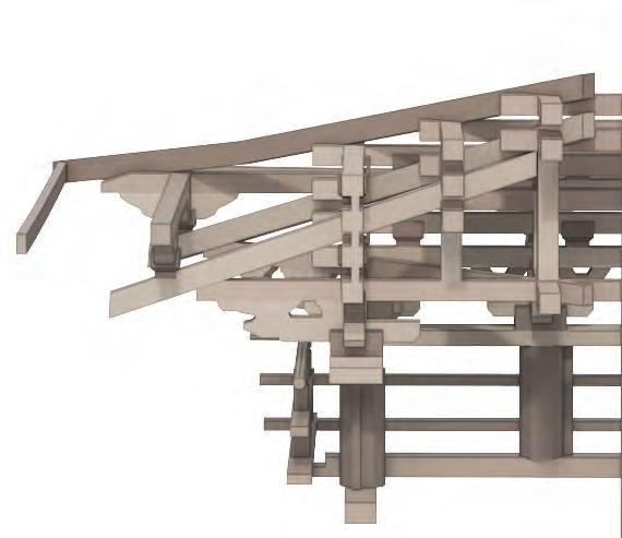
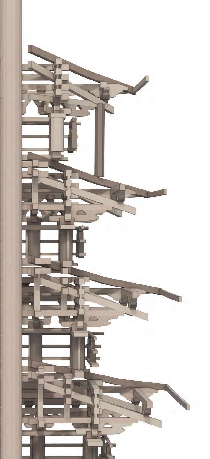
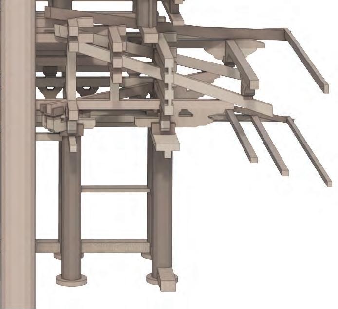
An earthquake can cause lateral displacement in a pagoda. The lowest box-like structure leans to the left, the one above it to the right, the one above that to the left, and so on, similar to a person performing a snake dance.
14 SECTION 1 ARTEFACT RESEARCH
Load-Bearing Column LEVEL 1 LEVEL 2 LEVEL 3 LEVEL 4 LEVEL 5
Shock absorbing column Gap space
eave load load from level 4
ROOF - BALANCING MECHANISM
The deep eaves in Japanese traditional architecture are supported by employing ‘levering’ and ‘cantilevering’ principles through bracket complexes.By extending the beam beyond one of the supporting points and implementing the lever principle, it can sustain a certain load placed on the beam outside of its span.Thus, the eaves construction uses side pillars as fulcrums and the eaves as levers
15 Level 4 Level 3 Level 2 1 2 3 4 5 1.7 ARTEFACT RESEARCHHORYUJI PAGODA - LOAD TRANSFER MECHANISM
Forming Triangle
Truss Action
tail rafter bracket arm rafter side pillar cloud-shaped bracket
Principle of Lever
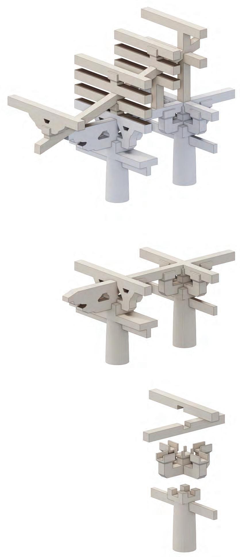
By stacking the members in this manner, the direction of the wood fibers alternates horizontally and vertically, which makes the structure more rational.
Bracket system for the point where two horizontal members intersect.
BRACKET AND DOWEL SYSTEM
The bracket complex comprises two basic parts: the bearing block and the bracket arm. It firmly supports the horizontal members, such as beams, crossbeams, and braces, that bear the weight from above, effectively transmitting the force to the pillars. Its purpose is also to provide support for the extended eaves by relocating the support points of the corner beams and eave rafters beyond the pillars
16 SECTION 1ARTEFACT RESEARCH
Side pillar Inner pillar
Bracket arm
Glulam-Timber componentsCurved Glulam-Timber components

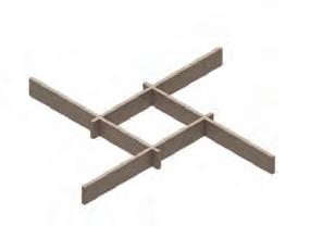
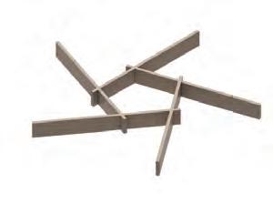
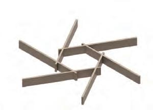
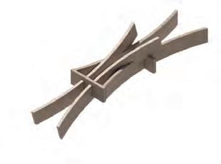
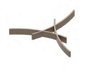
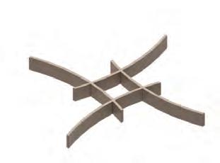
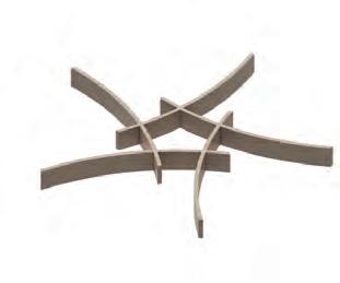
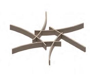
RECIPROCAL STRUCTURE
Reciprocal 3 dimensional aggregation
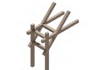
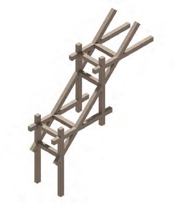
Curved components
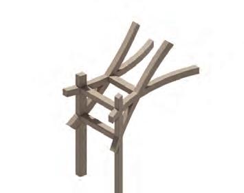
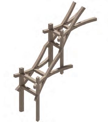
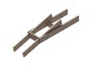
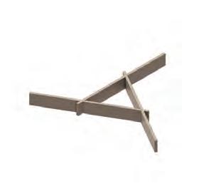
The reciprocal structure has no central node but provides mutual support to each other. The study investigates the development of a reciprocal structure in curved components.
17 1.8 ARTEFACT RESEARCHRECIPROCAL STRUCTURE EXPLORATIONS
Triangle Square
Pentagon
Hexagon
Angular change
TIMBER FRAGMENT EXPLORATION I
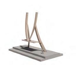
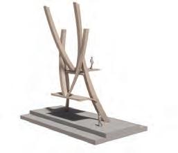
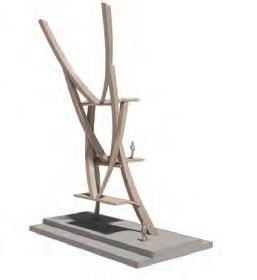
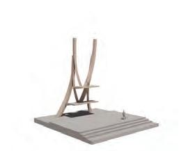
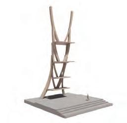
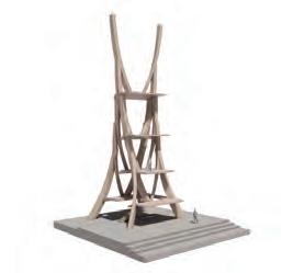
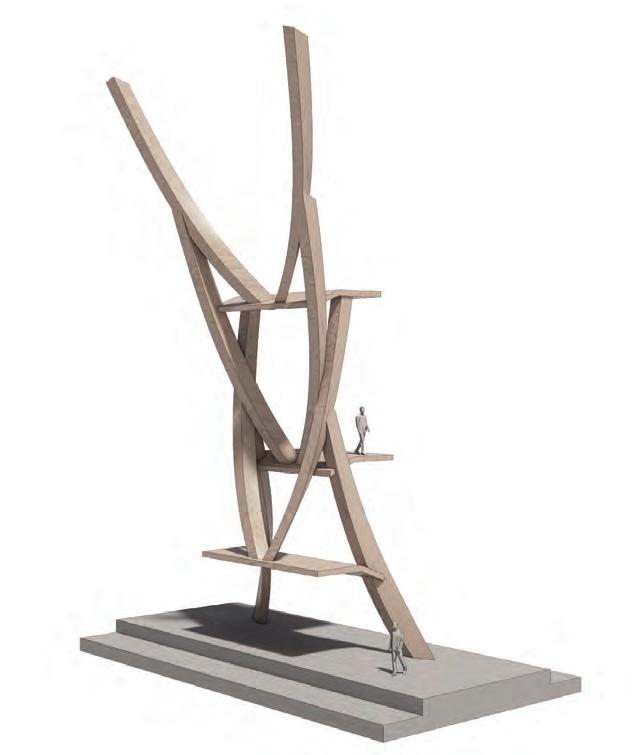
The investigation of the combination of curved components in overlapping stacking is further examined in vertical aggregation by altering the angle.
18 SECTION 1 ARTEFACT RESEARCH 1.9 ARTEFACT RESEARCHFRAGMENT EXPLORATION I
Branching morphologies
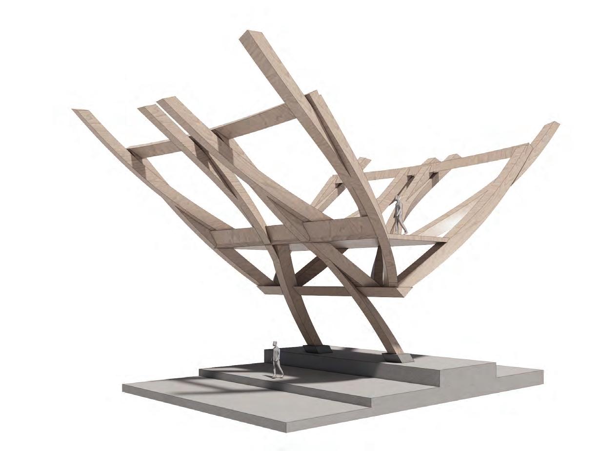
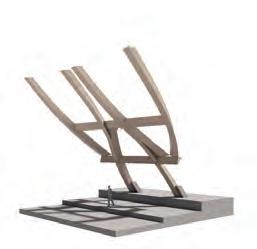
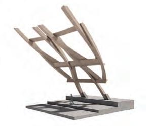
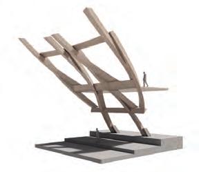
TIMBER FRAGMENT EXPLORATION II
Another investigation into the principles of bifurcation, examining the branching morphologies that occur through alternating angles and diagonal expansion.
19 1.10 ARTEFACT RESEARCHFRAGMENT EXPLORATION II
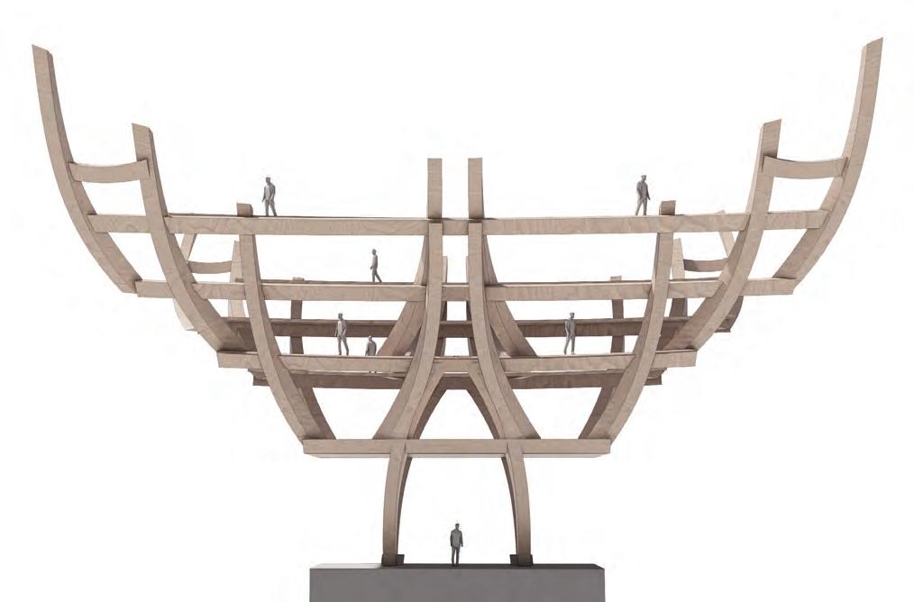
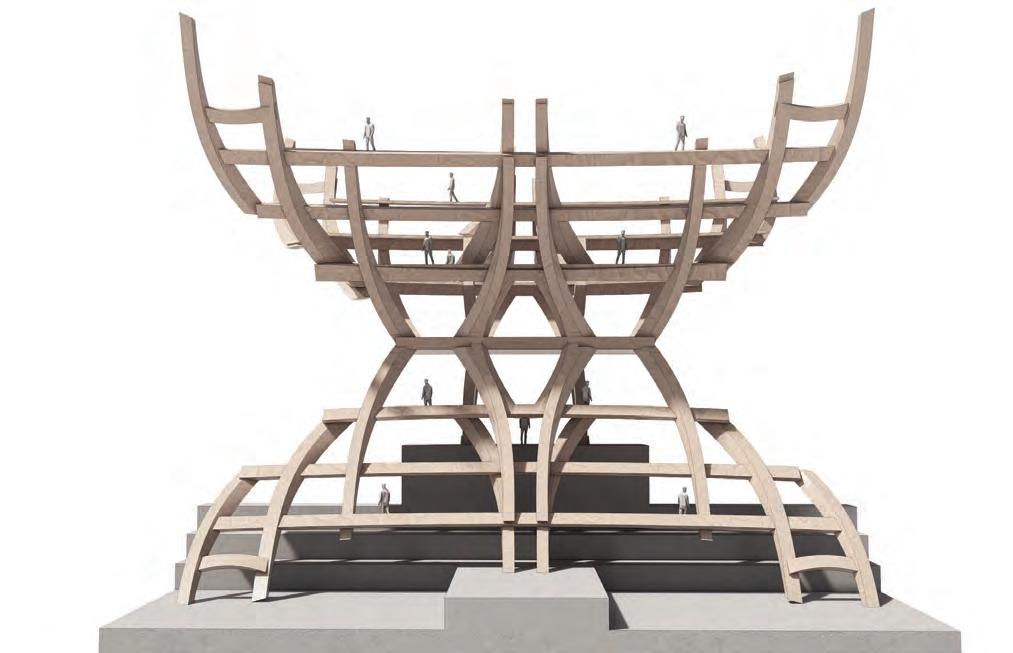
TIMBER FRAGMENT - AGGREGATION
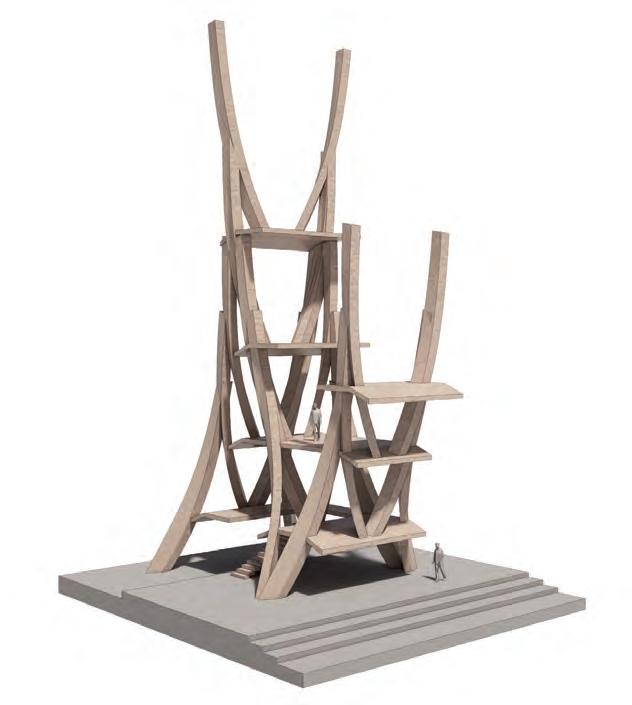
The earlier work on fragment analysis is expanded by examining the threedimensional stepping cantilevering stacking method to maximise the use of floor space while decreasing the floor area.
20 SECTION 1 ARTEFACT RESEARCH
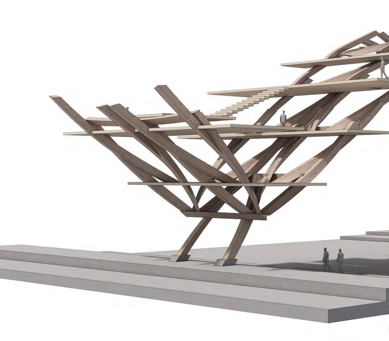
21 1.11 ARTEFACT RESEARCHFRAGMENT EXPLORATION III
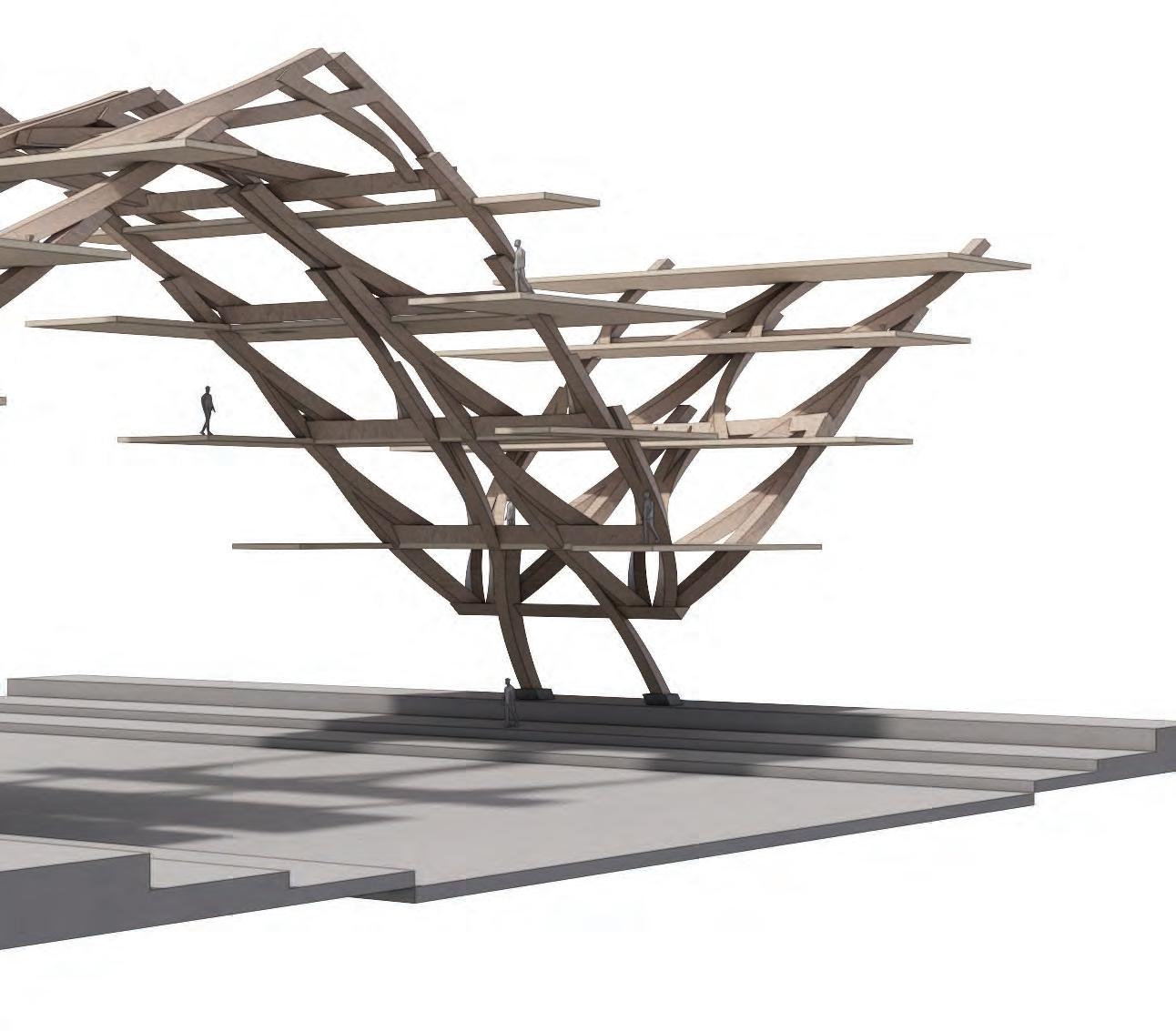

TECTONIC FRAGMENT - ORTHOGONAL ARRANGEMENT
The concept of offsetting is expanded upon in the cantilevering system, which utilises the technique of offsetting between parts and weaving to create a bigger aggregated system.
22 SECTION 1 ARTEFACT RESEARCH
SECTION 2: BRIEF AND CONTEXT
02


NORTH KOREA





Major Ports
Ferry
0m 10m 25m 5m
100m 50m 150m+


East China Sea























2
Yellow Sea
2.1 BRIEF AND CONTEXTCONTEXTUAL RESEARCH - TOPOGRAPHY OF JAPAN
SOUTH KOREA
CHINA
RUSSIA































North Pacific Ocean






PROJECT SITE - JAPAN

377,973.89 km2


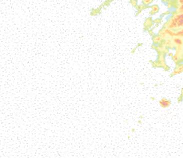
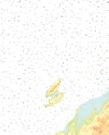
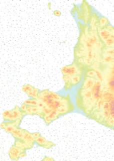
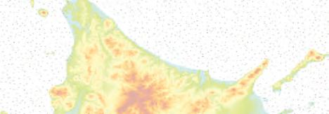
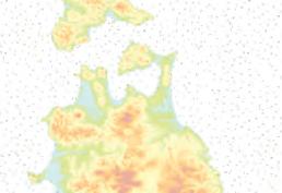
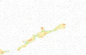
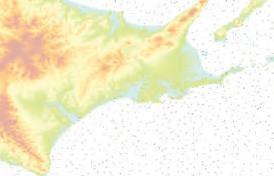
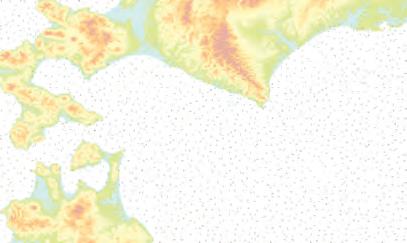
Japan is predomminantly mountainous, about 3/4 of the national land is mountains. The country comprises of a stratovolcanic archipelago over 3,000km along the Pacific coast of East Asia. It consists of 14.125 islands. Geographically cut off by the oceans surrounding it, the historical events that have taken place there are relatively distinctive and influential.


SEC C EC E TIO O ION 2 N2 N PROOJEC C JEEC J T B TBBRIE IE I F 26 RUSSIA
Sea of Okhotsk
Philipine Sea
JR KYUSHU (KYUSHU)
HOKKAIDO SHINKANSEN JR EAST (TOHOKU) JR EAST (JOETSU) JR CENTRAL (TOKAIDO) JR WEST (SANYO) JR WEST (HOKURIKU)
Line Start End
Tokaido Shinkansen
Sanyo Shinkansen
Tohoku Shinkansen
Joetsu Shinkansen
Hokuriku Shinkansen
Kyushu Shinkansen
Nishi Kyushu Shinkansen
Hokkaido Shinkansen
Tokyo
Shin-Osaka
Tokyo
Omiya
Takasaki
Hakata
Takeo-Onsen
Shin-Aomori
Shin-Osaka
Hakata
Shin-Aomori
Niigata
Kanazawa
Kagoshima - Chuo
Nagasaki
Shin-Hakodate-Hokuto
TRANSPORTATION NETWORK
Shinkansen, or ‘bullet train,’ originally ran on the Tokaido line in 1964 and now spans 2,830 km with top speeds ranging from 240 to 320km/h.
TRANSPORTATION LEGEND
Main Cities
Shinkansen station
JR Hokkaido
JR East
JR Central
JR West
JR Kyushu
174,171,000 76,007,000 93,489,000 44,452,000 31,670,000 14,488,000 1,601,000 Annual Passengers
195 million passengers/year (2021)
27
2.2 BRIEF AND CONTEXTJAPAN - TRANSPORTATION NETWORK
SAPPORO
Length (km) 515.4 553.7 674.9 269.5 345.4 256.8 66.0 148.9
1964 1972-1975 1982-2010 1982 1997 2004 2022 2016
Opened
OSAKA


Japan
of


ECONOMY AND INDUSTRY OF JAPAN


SECTION 2PROJECT BRIEF 28
TOKYO
Japan: Distribution of GDP across different industries Construction Others Manufacturng Service Real Estate Wholesale and Retail 5.4% 17.5% 20.5% 32.1% 11.8% 12.7% 2.3 BRIEF AND CONTEXTJAPAN - ECONOMY AND INDUSTRY
is ranked as the third largest economy, with manufacturing being the largest portion
its GDP. This visualisation of prominent Japanese corporations illustrates the extensive dispersion of the Japanese industrial sector around the nation.
WORLD’S MOST POPULATED CITIES
Total population: 124,631,000 (2022)
126,803,861 128,105,431 127,250,933 126,993,857 126,662,427 126,255,866 125,791,677 125,244,761 124,612,530 123,951,692
POPULATION DENSITY
The total population of Tokyo reaches 38 million people when the adjacent metropolitan areas of Kanagawa, Saitama, and Chiba are taken into account. With a population of over 124 million people, Japan has the distinction of being home to the world’s most populated urban area, Tokyo, which accounts for nearly 30% of the country’s total population.
29 POPULATION DENSITY 2020 1. TOKYO 37m
7. SENDAI 2.3m
6. SAPPORO 2.6m
8. HIROSHIMA 2.0m
2. OSAKA 13m
50 50 ~100 100 ~200 200 ~300 300 ~500 500 ~700 700 ~1000 1000 ~2000 2,000 + Tokyo Metropolitan Japan 34,450,000 36,860,000 37,256,000 37,327,000 37,397,000 37,468,000 37,435,000 37,393,000 37,340,000 37,274,000
2000 2010 2015 2016 2017 2018 2019 2020 2021 2022 *The data shows that the population of Japan has reach its peak in 2018 and decline slightly each year since then
3. NAGOYA 9.5m 5. SHIZUOKA- HAMAMATSU 2.9m 4. KITAKYUSHU-FUKUOKA 5.5m
Tokyo Shanghai Delhi Dhaka Sao Paulo Cairo Mumbai Mexico Beijing Osaka 37.3 m 28.5 m 32.1 m 22.5m 22.4m 21.8m 21.0m 22.1m 21.3m 19.1m 2.4 BRIEF AND CONTEXTJAPAN - POPULATION
2050 DEMOGRAPHIC CRISIS
The population in which the proportion of individuals aged 65 and above is more than 20%, with predictions indicating that by 2050, 40% of the population will be above the age of retirement. The combination of a high life expectancy and a low reproduction rate necessitates immediate attention to national and economic security.
SECTION 2PROJECT BRIEF 30
YOUNG ADULT DECLINE FORECAST 2040 TOKYO OSAKAKYOTONAGOYA A rural location with a high level of young adult declune is anticipated. In 30 years, age group of 0-45 has dramatically decreased 20 ~ 10 ~20 0 ~10 -10 ~0 -20 ~-10 -30 ~-20 -40 ~-30 -50 ~-40 -60 ~-50 -70 ~-60 -80 ~-70 -90 ~-80 0 150 ten thousand ten thousand 10050050100150 5 10 15 20 25 30 35 40 45 50 55 60 65 70 75 80 85 90 95 100+ 1989 2018 4 MAJOR CITIES OF JAPAN
DEMOGRAPHIC CRISIS

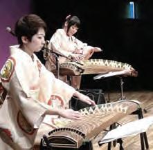
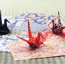
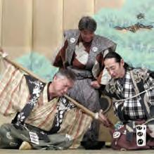

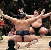



ENTERTAINMENT INDUSTRY
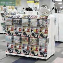
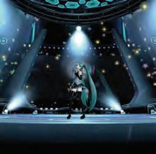
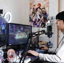
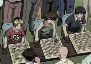
An investigation into the entertainment sector in Japan with a specific emphasis on contrasting traditional and contemporary types of entertainment.
31 2.5 BRIEF AND CONTEXTROJECT BRIEF - ENTERTAINMENT INDUSTRY
Traditional
Kabuki
KotoSumo
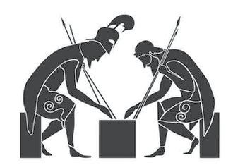
Shogi
Origami
Gachapon
Kyogen
Cosplay
Video games
Anime
Idol - girl groupVocaloid Contemporary





POP CULTURE (Manga/Animation)
Mind Sports

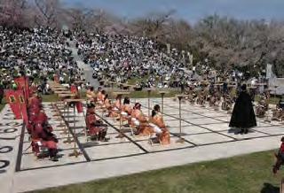
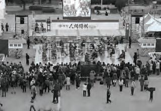
MIND SPORTS ENTERTAINMENT
SECTION 2PROJECT BRIEF 32
Naturo - Shikamaru Nara
Shogi Sasu Kedamono
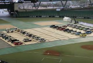
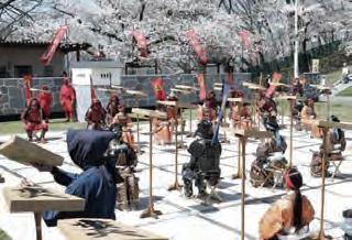
Human Shogi
Bonus: Hikaeu no Go
March Comes in Like a Lion
g A game of skill based on intellectual aptitude could be the future of entertainment for a ‘hyper-aged’ society in Japan.
Shion no Ou (The Flowers of Hard Blood)
Mind Sports Olympiad
The Ryuo’s Work is Never Done!
(at Tendo Sakura Festival, Yamagata)
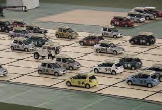
SCALING UP THE BOARD
Car Shogi
20 pieces 81 square board
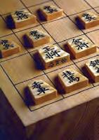
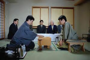
SHOGI - JAPANESE CHESS
33 2.6 BRIEF AND CONTEXTROJECT BRIEF - SHOGI (JAPANESE MIND SPORT)
9×9
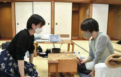
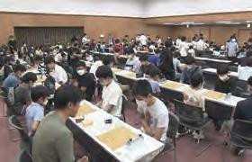
Shogi, one of Japan’s most popular board games, is a game of skill focused on intellectual aptitude that is regarded more difficult than international chess.
Mind Sport
piece stand
10 millions players 9 pawns 2 lances 1 king 1 rook 1 bishop 2 gold generals 2 silver generals 2 knights
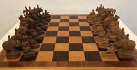



Spread to Japan
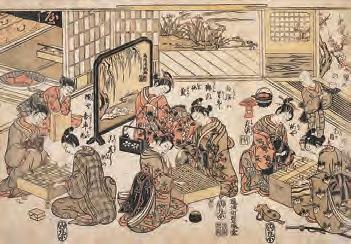
It is thought to have originated in India and was passed on to Japan via China and Korea.
More difficult than chess - because once players capture an opponent’s piece, they can use that piece as their own—meaning that while chess games on the whole get simpler as fewer pieces are left on the board, shogi gets more complex
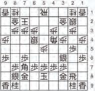
The diary of the Matsudaira clan dated 1587 February
Castle Shogi Tournament once a year
Shogi Day - 17th November is designated as Shogi day since then.



SECTION 2PROJECT BRIEF 34
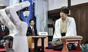
Computer Shogi - Robotic Player (DENSO)
2014
Super human
When Japanese Capital moed from Nara to Kyoto
Earliest Shogi Record
Robotics in Shogi
Human lost Robot for the first time
Mind Sport Olympiad, London
Robotics in Chess
6th century 15 87 1980 1997 2012 2017 1720s 5th century
Chaturanga, India
World Japan


SHOGI RANK SYSTEM
35
amatuer shogi competition
individuals were elevated to the rank of 4th dan in the biannual 3rd dan league.
Professional Professional Level Promotion Professional Amatuer skill level equivalence skill level equivalence Individuals who have attained excellent results in amateur competitions are eligible to participate without the endorsement of a master 9 dan 8 dan 7 dan 6 dan 5 dan 4 dan 3 dan 2 dan 1 dan 1 kyu 2 kyu 3 kyu 4 kyu 5 kyu 6 kyu S A1 A2 B1 B2 E1 E2 F1 C1 C2 D1 D2 F2 Request into Women Professioanl Request into Professioanl 7 kyu 8 kyu 9 kyu 3 kyu 2 kyu 1 kyu 1 dan 2 dan 3 dan 4 dan 5 dan 6 dan 7 dan 8 dan 9 dan 4 kyu 5 kyu 6 kyu 10 kyu TrainingSession Organisation AmatuerBeginners Mentor Commendation Exam Exam Commendation Exam Young adults Women professional Men professional 2.6 BRIEF AND CONTEXTROJECT BRIEF - SHOGI (JAPANESE MIND SPORT)
Largest
Two
Women
ranking systems of shogi plays
a design parameter
Considering different
as
Non-Industrial Robots
Humanoid Robot Mecha

Human Companions Robots





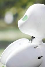

Teach English Interact and live with Emtional caring Receptionist Solve loneliness and help with physical disability Optimised for human interaction SOFTBANK ROBOTICS ORY LAB INC
NEC CORPORATION
INTELLIGENT SYSTEM RESEARCH INSTITIUE OF JAPAN AKA INTELLIGENCE
Industrial Robots

1 robots every 15 people
Japan has about 631 robots every 10,000 human in manufacturing sector, while the US has 274 robots. Japan is the largest manufacturer and exporter of industrial robots, with 45% of global supply and only 2% is imported. (As of 2022)

1 robots every 35 people
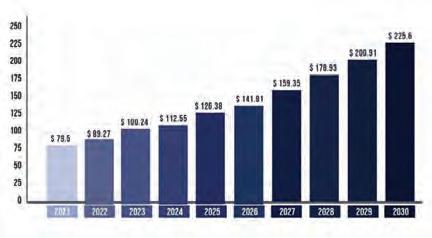
By 2030, the robotics market is projected to triple.
THE LAND OF RISING ROBOTICS
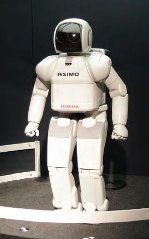
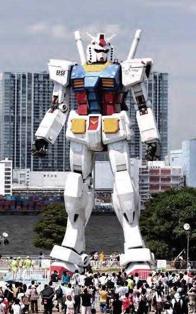
Japan has a robust relationship with the robotics industry, and non-industrial robots, serving as human companions, can assist elderly individuals in maintaining their health and activity levels at home by alleviating stress and loneliness.
SECTION 2PROJECT BRIEF 36
AIBO
LOVOT
GUNDAM
ASIMO
2.7 BRIEF AND CONTEXTPROJECT BRIEF - ROBOTICS INTEGRATION
MITSUBISHI
Multi functional mobile assistant
Soothing and healing
Entertainment HONDA LOVOT -GROOVE X AIBO - SONY
BANDAI NAMCO
Future of Robotics Market
Social Robots - comunications
PaPeRoWAKAMARU
WIPO PARO PEPPER MUSIO
1500-1899
1900-1955
1956-1975
1976-2015
TOKYO BAY ‘UMETATECHI’
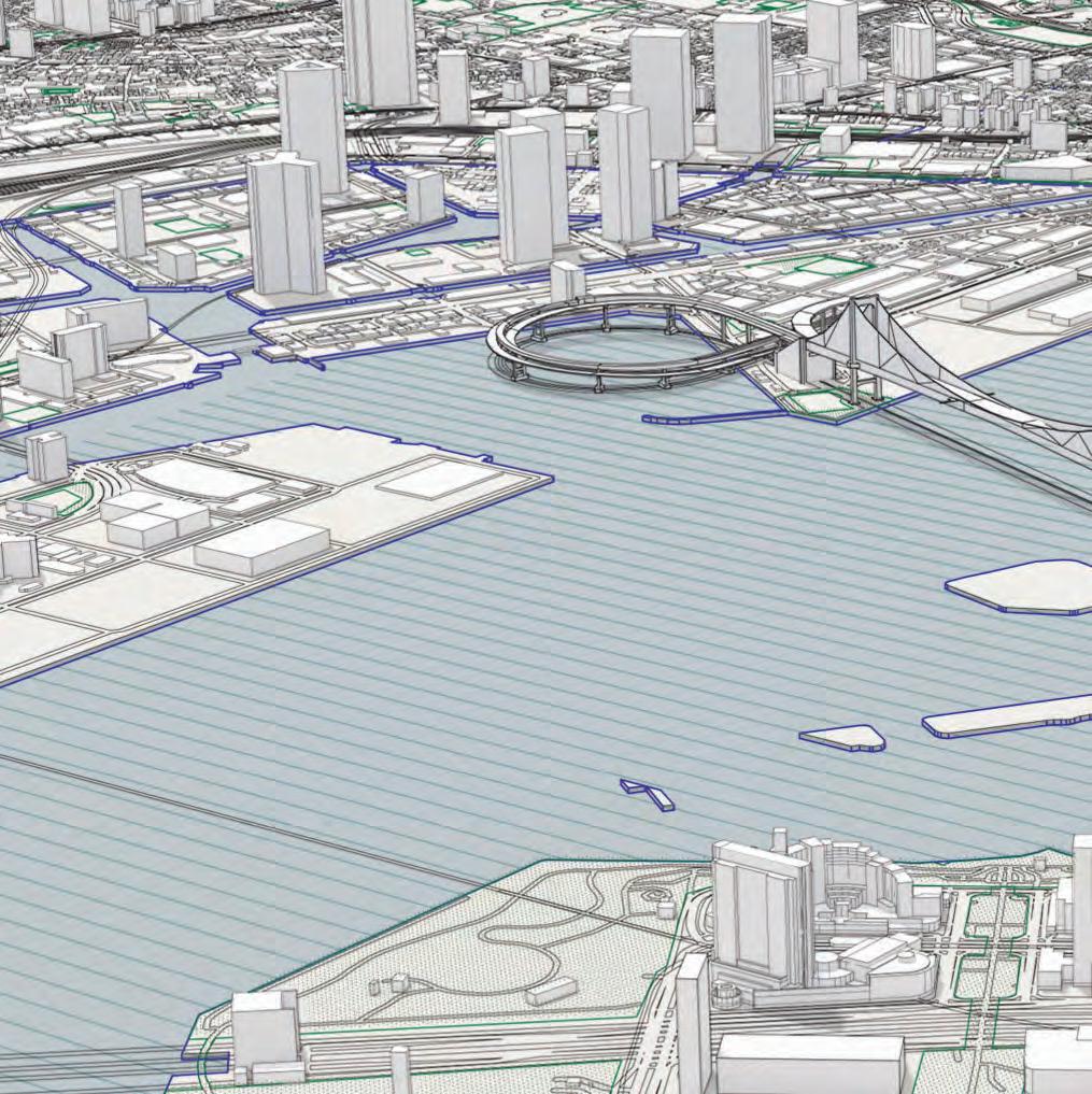
Land reclamation has been employed since the 16th century to create additional area for expansion, manufacturing, and other activities. The utilisation of reclaimed land has been crucial in meeting the increasing demands of Japanese society, especially in densely populated urban regions where land availability is restricted.
37
2.8 BRIEF AND CONTEXTROJECT SITE - TOKYO BAY
CHIBA
Aqua-LineExpress
TOKYO
KANAGAWA
GUNDAM
RaibowBridge
Train Station
Rinkai Line
Odaiba Area on n entation n a o t t i en e st Orie Or Techno-Futurist Or T ist itO O st s Orien n Futturi no uturistFuturis an rom an urban kyo Bay from y hift at Toky The shift at Tok Th T atTokyoBayfro a h B he shhi h ay Tokyo B Bay y a ky at rom community mununittycommuni m del living com od d ” and mod d subcenter” m “ “su “s s “subcenter” “subcenter”andmodmode mo o “subbc su r” mo b t nt nce ceen n er er” r m mode nt district di d ent t ainment nmmen m rict nt tertainmnteteertain t and anddenente d ping a pinng hoppingshopppin ho a assh o a to a to a shopping a t g an oashoppingan n toashoppingand and sho sh ip ainm an me hift from t hift f shift f etal shif a al s m ta larger societ e eta t et mirrored a larg m mi mirrored a reddllar ala o a or lar mirrorore ro d r rr e re ning, guided by g lanning, guide nn uideed an a g n , gu n u nin ed ni cratic, utopian pla o lapl echnocratic, utop tec te e technocra ra o echnooc c echn pian crat bureaucra r an bure n bu u au bur opolitan polli po metroppoli e metr metro o tional and met nation na natio i attio ation metropolitan cies. Tokyo International

SECTION 2PROJECT BRIEF 38
N
Railway
Parks Pier
Lines Legends
Cruise Terminal
Sports
B
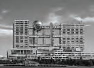
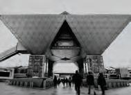
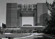
Train automated guideway transit service Cruise Ship Fuji Television HQTokyo Big Sight Tokyo Telecom CenterNational Museum of Emerging Science and Innocation convention center, featuring a conference tower of inverted titanium pyramids Transportatioin Techno-Futurist Vision SCALE 1:20000 1KM
Warehouses Container Terminal Tokyo Big Site National Museum of Emerging Science and Innovation Team Lab Borderless Joypolis Amusement Park Marine Park Statue of Liberty
Center Tokyo Port
k Yurikamome

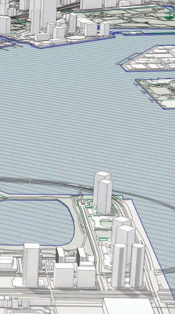
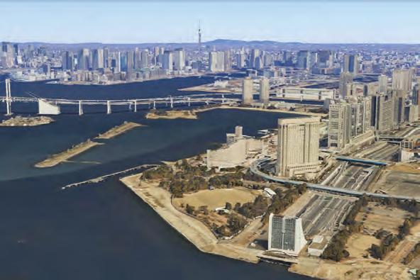
ODAIBA (ISLAND FORT) DEVELOPMENT



39
Battery Islands Before Land
Reclamation
A showcase for futuristic living redevelop the capital’s unutilised areas into new, bustling city centers
Buit for defensive purpose but never used due to a change in government policy and the
Soaring real estate prices in the bubble economy incentivized traditional land fill-based development 1850s 20th Century 1941 1990s Tokyo
2.9 BRIEF AND CONTEXTROJECT SITE - ODAIBA
Shinagawa offing Seaweed production area
conclusion of the Treaty of Peace and Amity
between Japan and the US.
Teleport Town Port of Tokyo Opened





SECTION 2PROJECT BRIEF 40 Train
TOKYO CITY
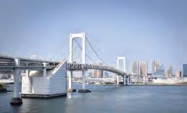
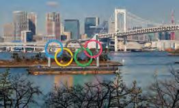
Olympics 2020 Rainbow Bridge
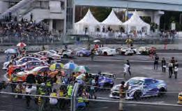
LineG1 Grand Prix Motorsport series International Urban Exposition 2020 2004 - 2018
Immediate context
+ Yurikamome
1993 1996
Connecting Shibaura Pier and the Odaiba waterfront
Drifitng events
Redevelopment to be completed in time for the exposition.
Beach volleyball at Shiokaze Park, triathlon and marathon swimming at Odaiba Marine Park, and gymnastics at a new gymnastics venue.
town tokyo big sight to hinode pier, asakusato shinbashi to hinode pier
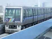
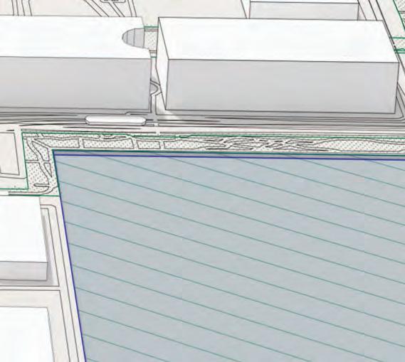
The location includes a train system that connects Odaiba Island to the city centre, as well as an elevated train system that links different areas inside the island. project site
EXISTING PUBLIC CONNECTIVITY
41
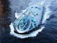
toyko water bus
odaiba seaside park
palette
to shin kiba
toyosu
shin-toyosu
shijo-mae
ariake tennis no mori
ariake
aomi
kokusai tenjijo tokyo bigsight
tokyo teleport
cruise terminal
daiba
tokyo international cruise terminal telecom center
to shinjuku
rinaki line (underground) yurikamome line (elevated line) water bus route
NNW NW WNW WSW SW SSWSSE SE ESE ENE NE NNE W S E N 2.10 BRIEF AND CONTEXTSITE ANALYSIS
Rinkai line
Yurikamome line
OVERGROUND ENTRANCE ZONE
F&B QUARTER
TRAINING QUARTER
EDUCATIONAL CENTRE
ROBOTICS PARK WATERFRONT PARK
URBAN PROMENADE
CULTURAL INNOVATION HUB
ROBOTICS INTERACTIVE/DISPLAY
B.O.H
RESTAURANTS
FIGURES CAFE MARKET
TRAINING ROOM
AMATUERPROFESSIONAL
SHOGI PARLOR ATRIUM
UNDERGROUND ENTRANCE ZONE
TRAIN STATION
INFORMAION WCs
RESEARCH LAB
ENTERTAINMENT HUB
MIND SPORTS STADIUM
CONTROL ROOM TAKEN AREA
WAITING AREA
PROGRAMMES FOR ‘ROBOTICS MIND SPORTS ’
TICKETING AREA
Tecnocratic Utopia - ‘increased leisure time, self-cultivation, and human creativity, as new communication networks enabled decentralised, flexible, harmonious social interactions’.
SECTION 2PROJECT BRIEF 42
2.11 BRIEF AND CONTEXTPROGRAMME - ROBOTICS MIND SPORTS STADIUM
SECTION 3: DESIGN DEVELOPMENT
03
45 3.1 DESIGN DEVELOPMENTSHOGI MOVEMENT Drum stage
Pieces
60
Captured pieces Controller tower Controller tower Stage Robotics Piece
Unpromoted
80 m
m
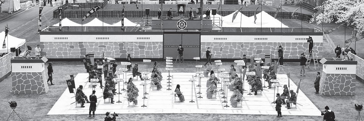
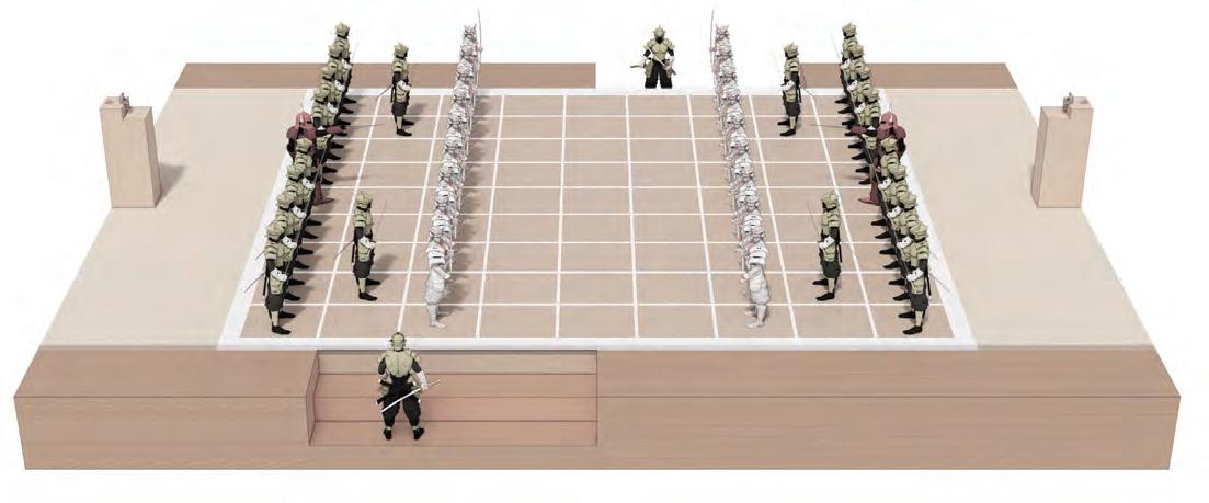
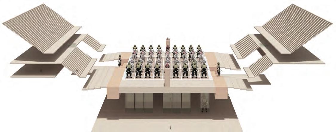
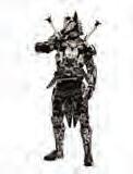
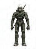
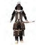
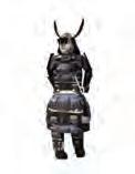
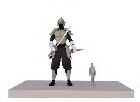
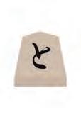
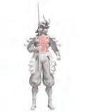
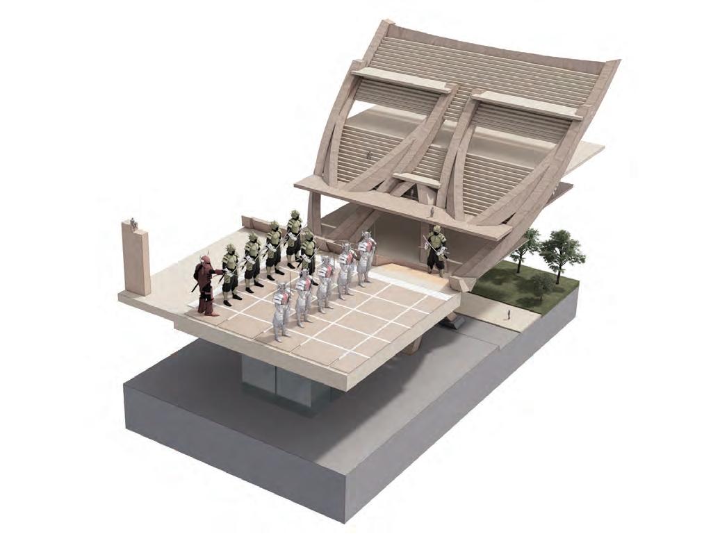
ROBOTICS MIND SPOPT STADIUM Scaling up the board and robotics pieces, considering the movement of the capturing pieces.









SECTION 3 DESIGN DEVELOPMENT 46
Shogi Pieces
King
Shogi Pieces Robotics PiecesRobotics Pieces Movement Movement
Narigin
Narikei
Narikyo
Tokin
Ryuo
Pieces Unpromoted Pieces
Ryume
Promoted
Gold Generals
Silver Generals
Knights
Lances
Bishop
Rook
Pawns
SHOGI
MOVEMENT
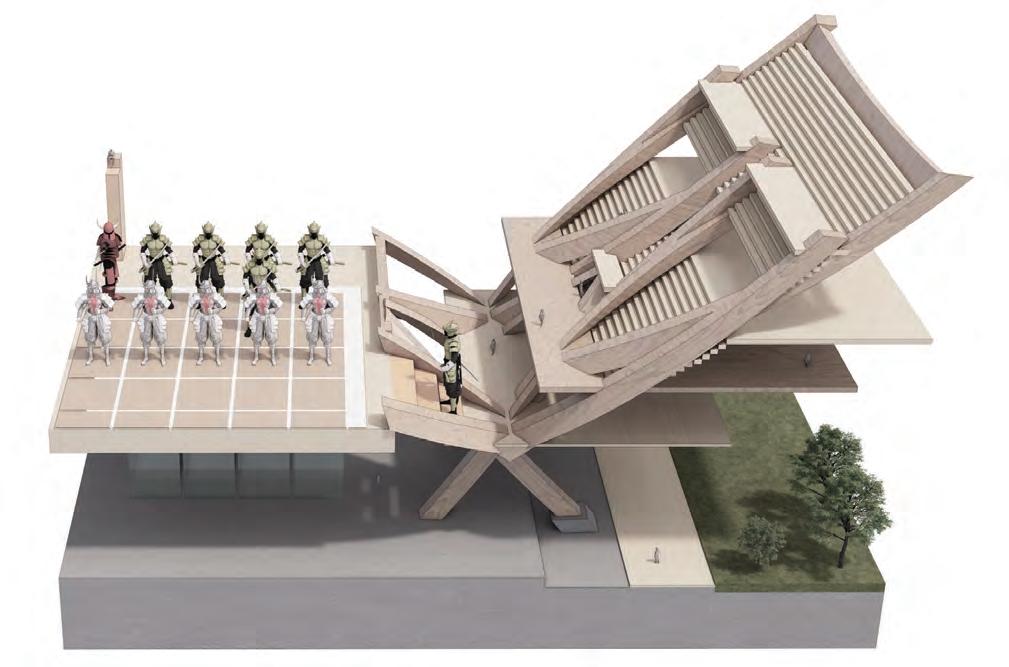
SPATIAL ARRANGEMENT STUDY
The initial design research primarily focuses on the disparity in size between the larger robots components and humans, as well as the vertical movement of these components. Additionally, the design takes into account the scale of the robotics elements while considering the elevated seating area.
47 3.2 DESIGN DEVELOPMENTEARLY EXPLORATIONS
Robotics Pieces movement
Robotics Park
Captured Capsules
Control Tower
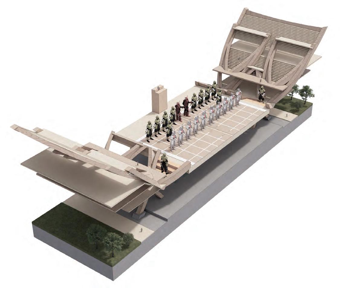
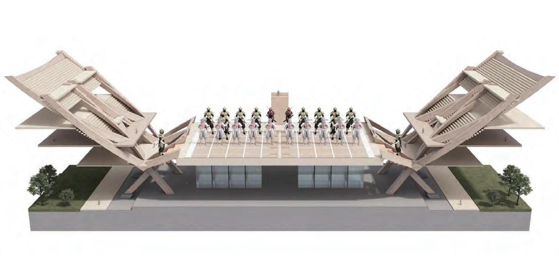
SPATIAL ARRANGEMENT STUDY
The aggregation of the fragment allows for the identification of its potential within a broader system, as well as the analysis of its spatial arrangement along the horizontal axis.
SECTION 3 DESIGN DEVELOPMENT 48
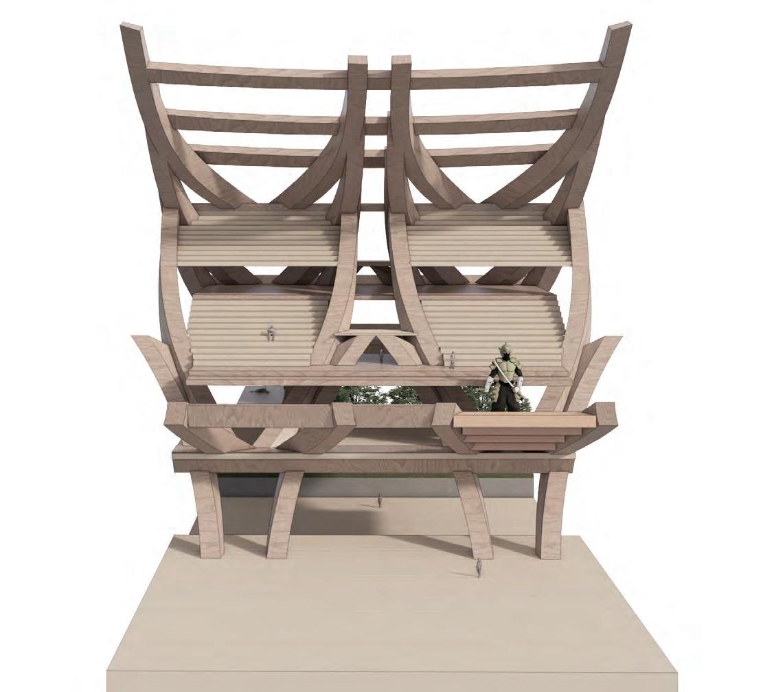
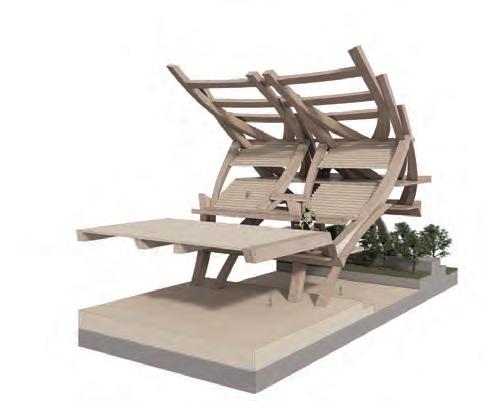
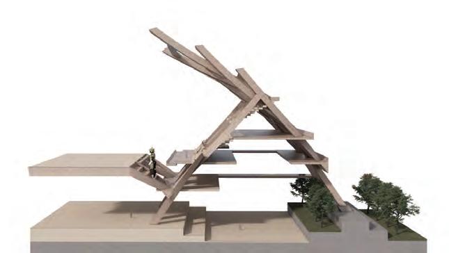
RECIPROCAL ROOF FORMATION EXPLORATIONS
This fragment further investigates the method of cantilevering stacking to create a roof structure. Additionally, it explores the possibility of designing an atrium space beneath the structural platform, which can serve as an urban promenade walkway.
49 Robotics
from ‘Practice’ to ‘Competition‘ Practice Zone (Amatuer) Professional rank Robotics competition 3.3 DESIGN DEVELOPMENTFRAGMENT DEVELOPMENT
level
Show/Transition
Audience
Seats arrangement Roof extension
Komadai
Outdoor stadia
Atrium
a
to hold robotics
Robotics stadia Taken area
place
Competition board
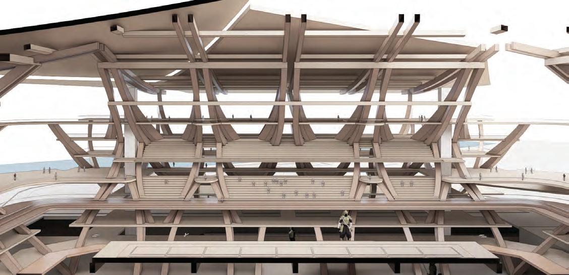
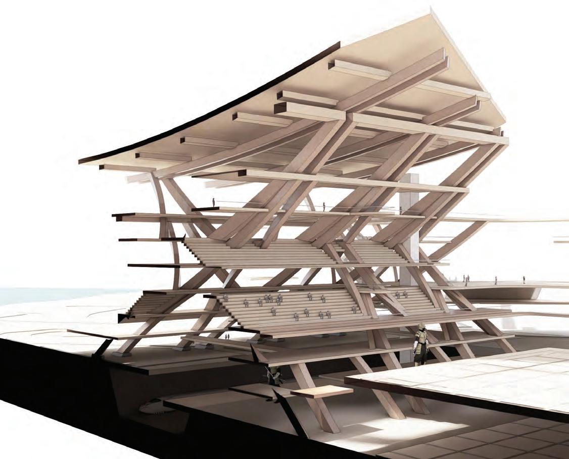
STANDS DESIGN
The consolidation of the fragment is examined to provide a platform for seating area. The space between the stage and the audience sitting area is specifically designated as the area where robotics pieces are positioned.
SECTION 3 DESIGN DEVELOPMENT 50
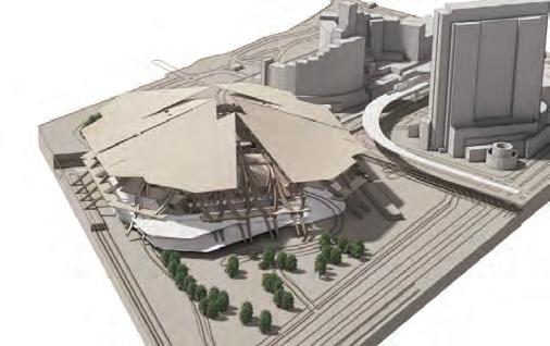
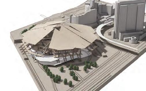
Planning strategy: diagonal to urban axis urban axis
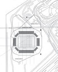
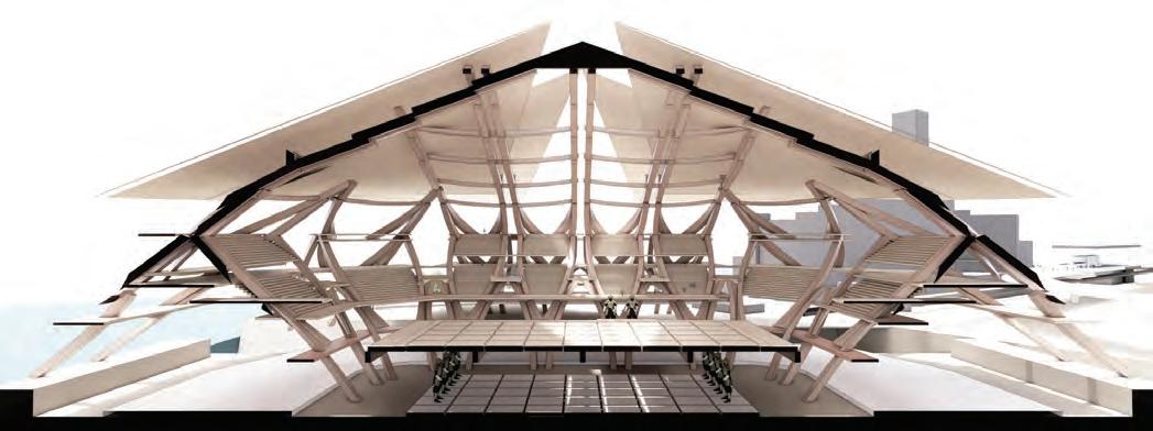
GLOBAL FORM ITERATIONS
Positioning the global structure in a diagonal manner relative to the urban axis results in reduced connectedness to its current urban environment.
51
Sectional study
3.4 DESIGN DEVELOPMENTGLOBAL FORM EXPLORATIONS
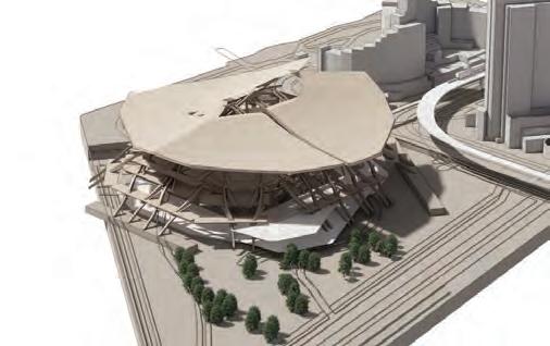
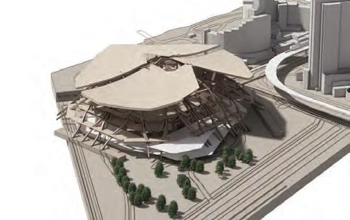
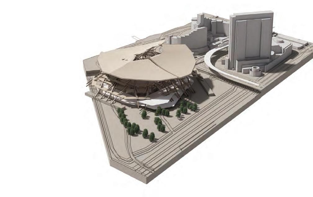
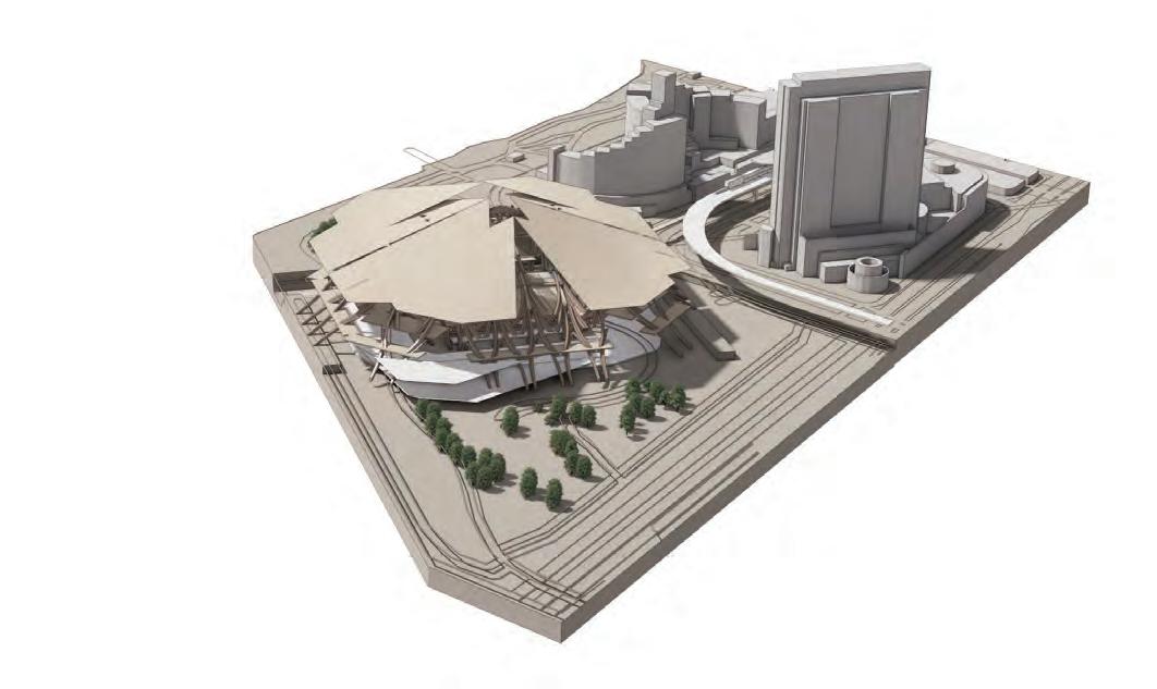
Planning strategy: parallel to urban axis urban axis
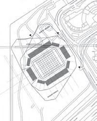
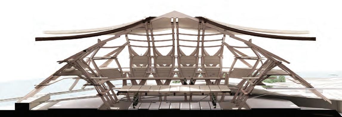
Sectional study
GLOBAL FORM ITERATIONS
Aligning the global structure parallel to the urban axis enhances its connectivity to the urban environment.
SECTION 3 DESIGN DEVELOPMENT 52


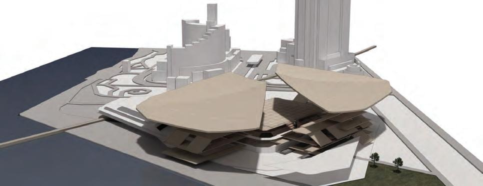
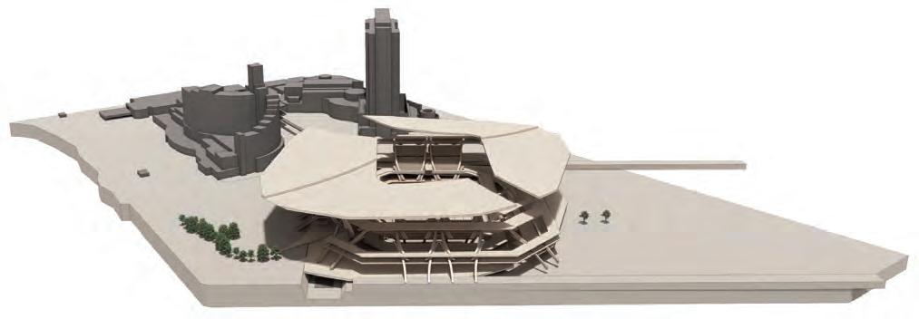
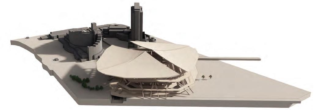
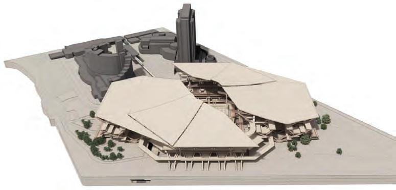

URBAN AXIS OPENING
The study investigates the correlation between the shape of a roof and its openings, as well as the stage located beneath it.
53 3.5 DESIGN DEVELOPMENTGLOBAL FORM DEVELOPMENT
URBAN AXIS
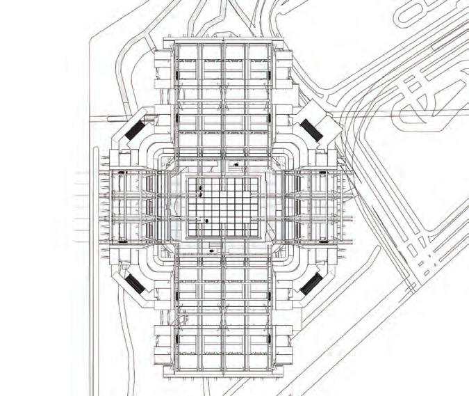
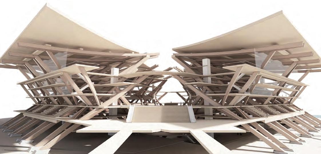
URBAN AXIS CONNECTION
Providing an entry point to the raised pedestrian pathway while creating a connection to the urban environment.
SECTION 3DESIGN DEVELOPMENT 54
Urban Axis
Entrance from the urban realm
SECTION 4: DETAILED DEVELOPMENT
04
Vertical loads exerted on the side pillar
load from above (N)
The simplified diagram depicting the basic idea of lever principle
overturning moment fulcrum fulcrum
Abstraction of the roof structure from the pagoda structure
extended roof structure
A point of ‘contraflexure’
At the point of contraflexure, the bending moment value is zero - neutral axis -
extended roof structure
LEVER PRINCIPLE
The principle of lever is applied to the morphology of the macro component. In order to prevent the occurrence of overturning, the fulcrums are positioned at two separate locations to maintain stability while allowing the roof eaves to extend in both directions. The examination of bending moments yields results regarding the thickness of the main structure and indicates the potential for reducing the thickness at that specific location.
57
Fulcrum
Fulcrum
fulcrumfulcrumsfulcrum
atrium
roof
F R N
load (F)
Fulcrum extension
4.1 DETAILED DEVELOPMENTROOF STRUCTURE AND ANALYSIS
PRIMARY STRUCTUAL COMPONENTS
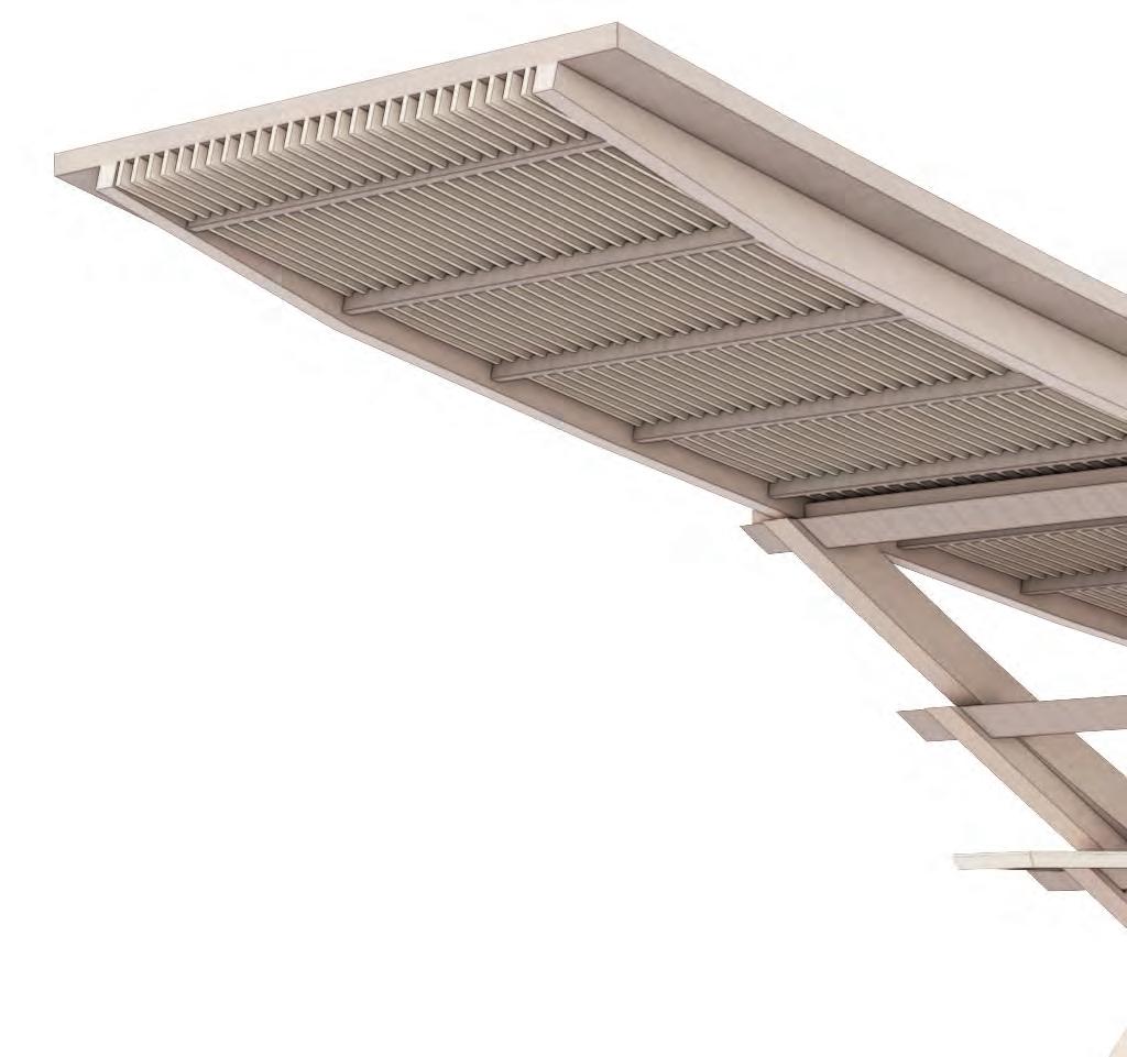
The construction of this structure necessitates that each component extends in a distinct direction with varying lengths to provide mutual support. The investigation thus focuses on the applicability of the structural principle of ‘reciprocal cantilevering stacked beams’ under these conditions.
SECTION 4DETAIL DEVELOPMENT 58
45O 35o 50o
Component # 1
Component #2
4.2 DETAILED DEVELOPMENTPRIMARY STRUCTURE
Component #3
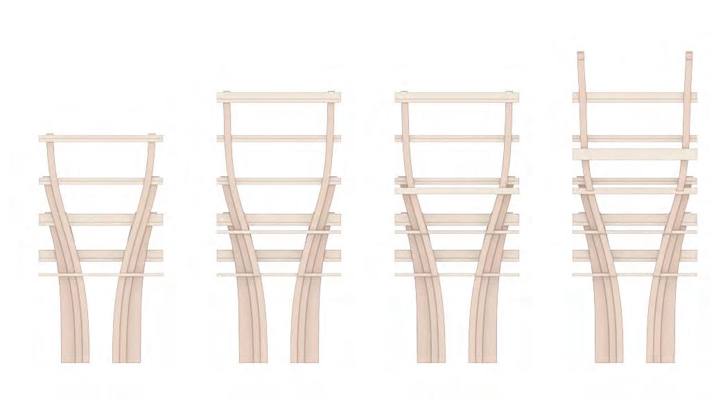
COMPONENT #1 DEVELOPMENT
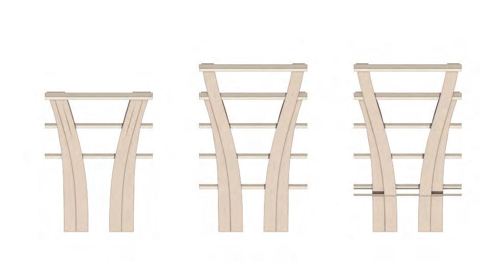
Within the broader structure, component #1 displays a 45-degree angle. The positioning of the cross beam is determined by the elevation of the slab. The placement of the cross beam establishes the position of the slab level, which ultimately decides the floor level, fixed at a height of 4.5 metres. This suggests that both the front and back cross beams have a dual function: connecting the stacked beam structure and supporting the weight of the slab.
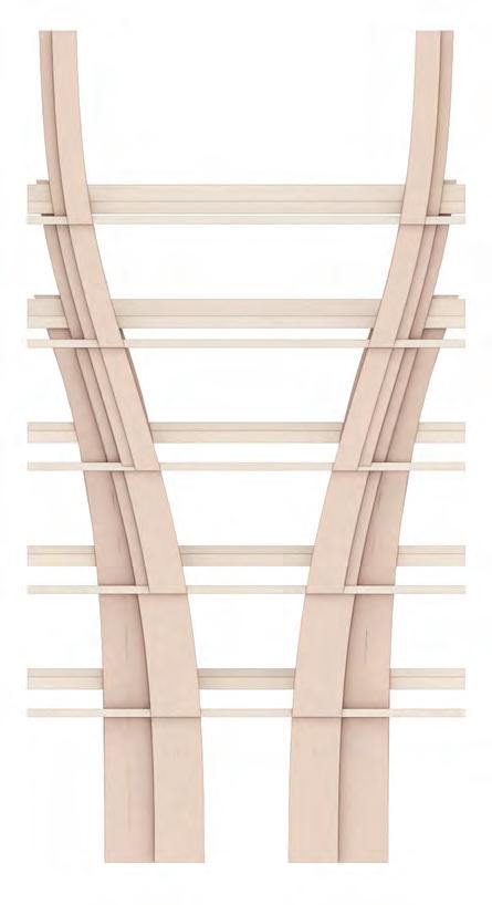
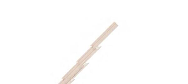
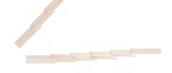
59 5.0m 5.0m 5.5m 1.21.21.21.2 10.5m 10.5m 5.5m 6.0m 6.0m 6.0m 6.0m 6.0m 4.5 m 4.5 m 4.5 m 4.5 m 4.3 DETAILED DEVELOPMENTSTRUCTURAL COMPONENT I
Base Assembly
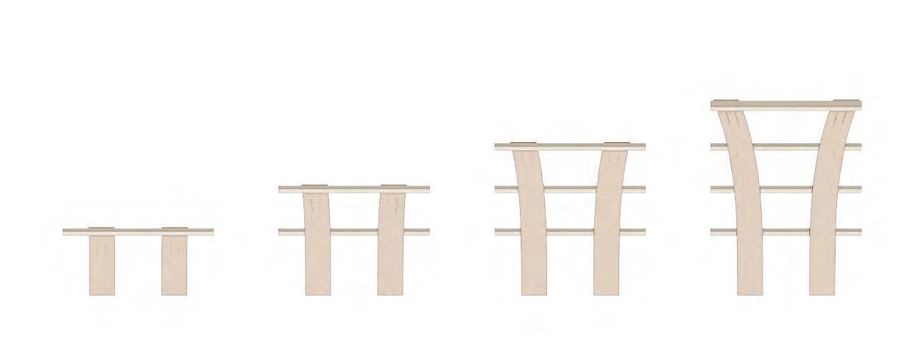
SECTION 4DETAIL DEVELOPMENT 60
Shifting Inward
01 First girder 02 Second gider 03 Third gider 04 Fourth gider - layer 1
Shifting fulcrums
Cross beam
05 Fourth gider - layer 2 shifting inward - changes in
08 Sixth gider 09 Seventh gider 10 Eigth gider 10 Ninth gider 06 Fifth gider - layer 1 07 Fifth gider - layer 2 forwarding the fulcrums at both ends
Girder
curvature
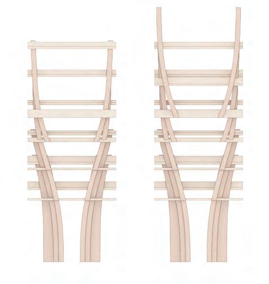
COMPONENT #2 DEVELOPMENT
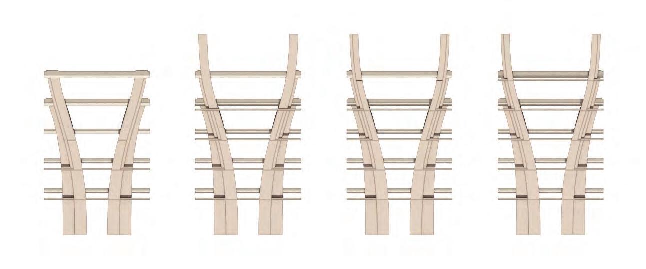
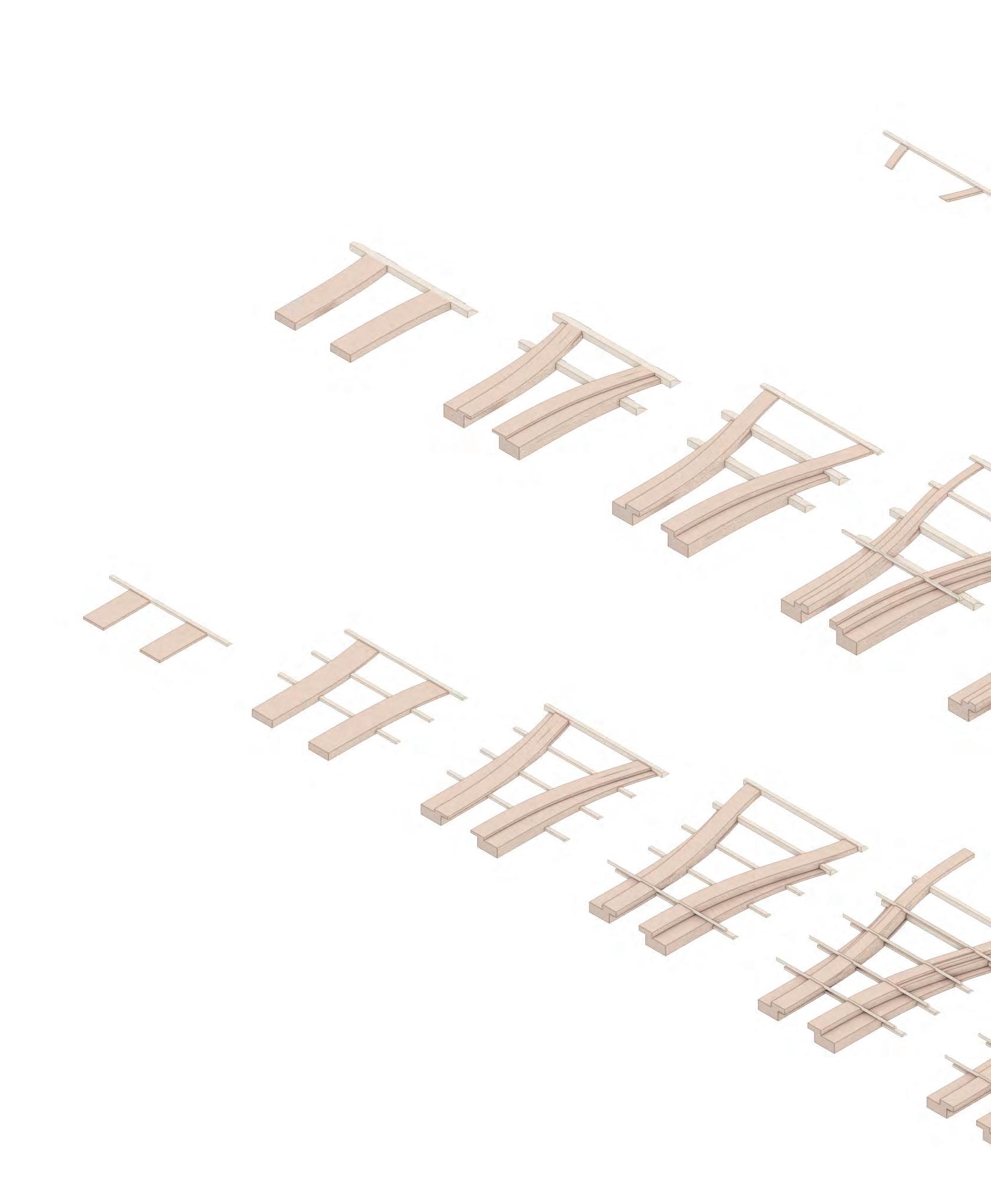
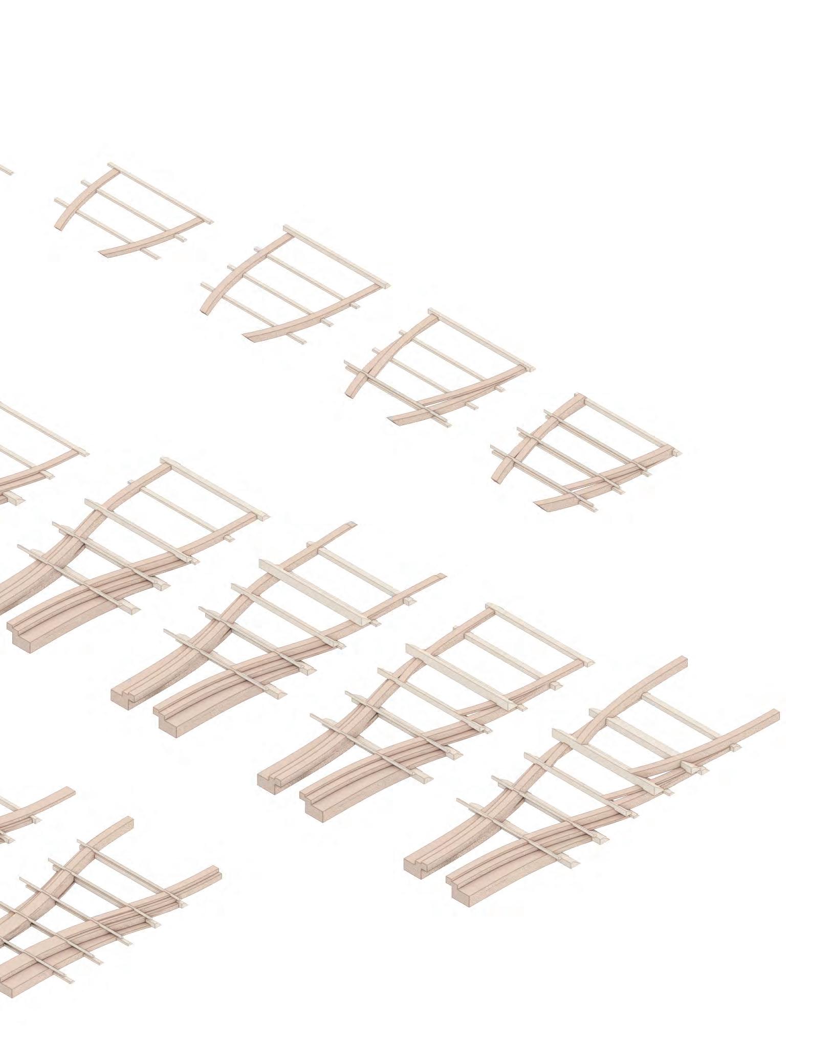
During the examination of bending moment, it was seen that component #2 experiences forces in two separate directions originating from components #1 and #3. Additionally, it experiences the highest level of stress compared to the other two components. An examination of the structure’s composition uncovers its inherent stress condition, which consequently signifies its thickness; at the point of maximum bending, the thickness is augmented, while at the point of opposite bending, it should be diminished.


61 5.0m 5.0m 5.5m 1.21.21.21.2 10.5m 10.5m 5.5m 6.6m 6.6m 6.6m 6.6m 6.6m 6.6m 4.5 m 4.5 m 4.5 m 4.5 m 4.5 m 4.4 DETAILED DEVELOPMENTSTRUCTURAL COMPONENT II 35o
in thickness
in thickness
in thickness
Increasing
Decreasing
Increasing
Base Assembly Shifting Inward
Shifting fulcrums
SECTION 4DETAIL DEVELOPMENT 62 01
02
03
04
05
06
07
07
08
09
connecting
First girder
Second girder
Second girder Inward shifting
Third
girder
Fourth girder
Fifth girder
Sixth girder
Seventh girder
Eigth girder
Ninth girder
point to the roof rafter
Shifting curvature
PRIMARY STRUCTURAL COMPONENTS
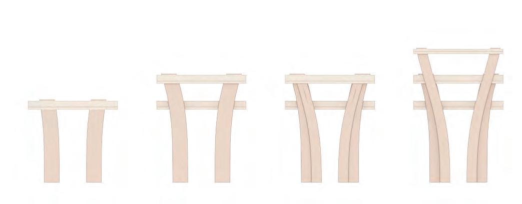
The system functions based on the premise of consistent width at every connection point, following the same structural concept while adapting the cross beams to match the desired slab level. The analysis involved assessing various curvature formations and determining that fulcrums may be moved to different locations while maintaining consistent shifting distances across all prototypes.
63
Base formation
Inward stacking
4.5 DETAILED DEVELOPMENTPRIMARY STRUCTURAL COMPONENTS
SECTION 4 DETAIL DEVELOPMENT 64
shifting curvature
shifting curvature
Component #1
Component #2
Component #3
Bending moment diagram with horizontal floors
JOINERY AND ASSEMBLY
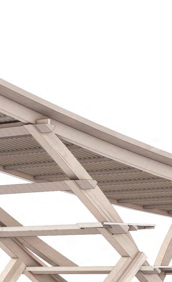
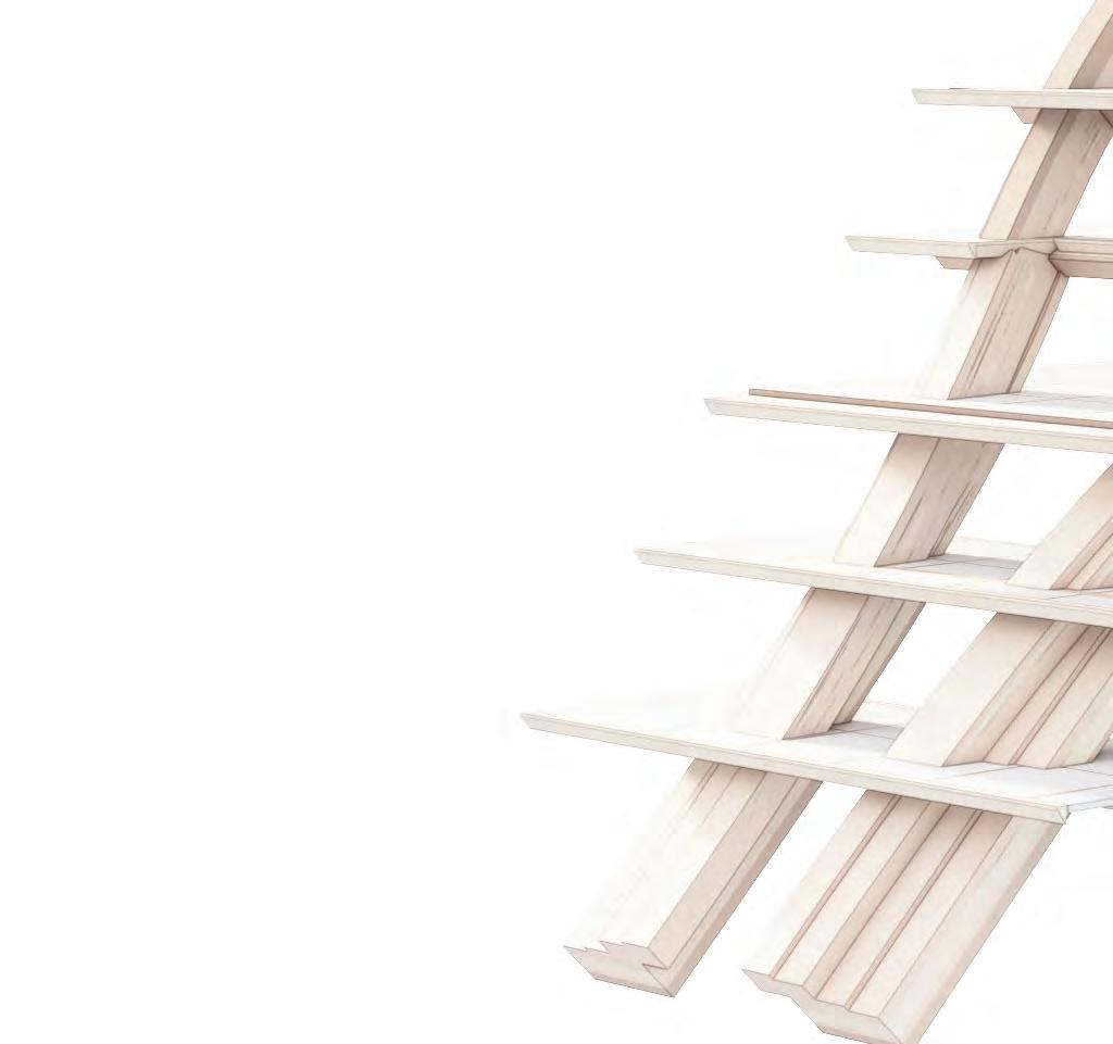
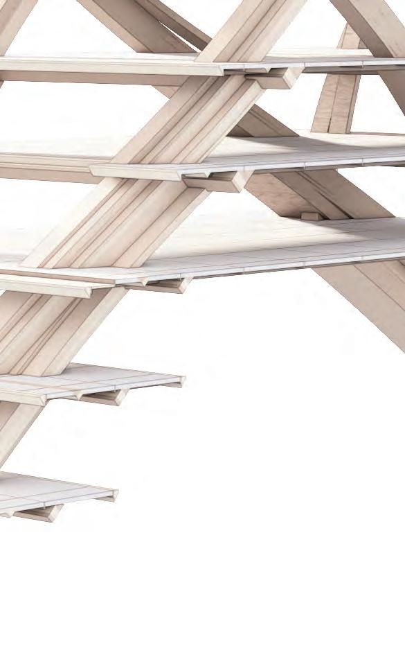
This illustrates a complete arrangement of the three main framework prototypes that have been created. The horizontal floors function as a stiffening element, linking the main structure on both sides of components #1 to #3 and causing them to move together horizontally when exposed to lateral forces. The uppermost and lowermost floors have the main responsibility for flexing among the three parimary stacking structures.
65
Location of secondary beams
4.6 DETAILED DEVELOPMENTJOINERY AND ASSEMBLY
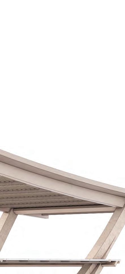
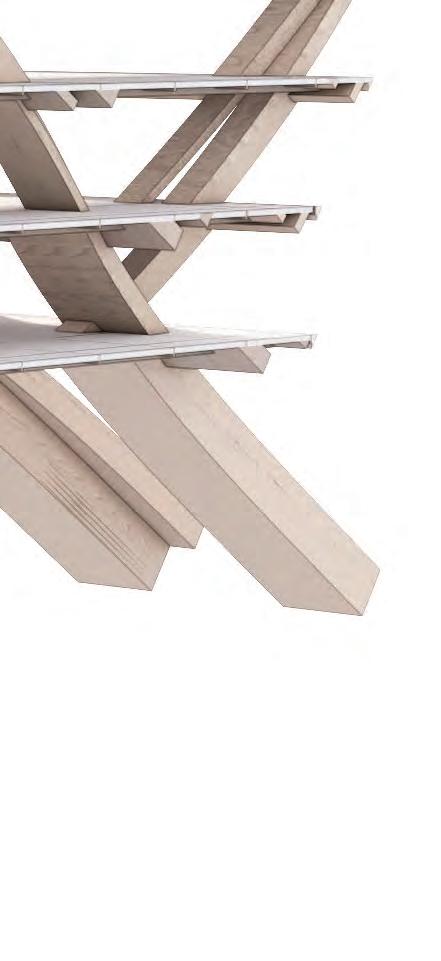

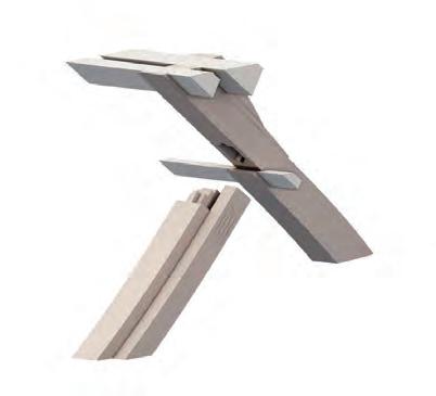
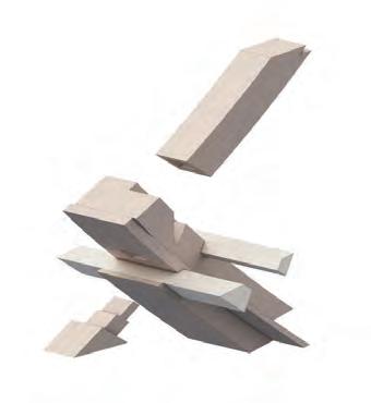
Component #1 to roof rafters connecting point
Component #3 to roof rafters connecting point
Component #1 and #2 connecting point
Platform integration
Component #2 and #3 connecting point
Component#2 and plinth connecting point
Component#1 and plinth connecting point
SECTION 4DETAIL DEVELOPMENT 66
cross beams roof rafter roof purlin stacked column stacked column stacked column stacked column component #1 component #2 component #3 cross beam component #2 component #3 component #1 stacked column concrete
stacked column
plinth
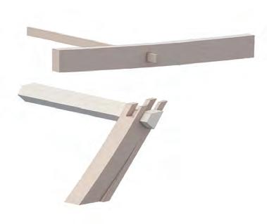
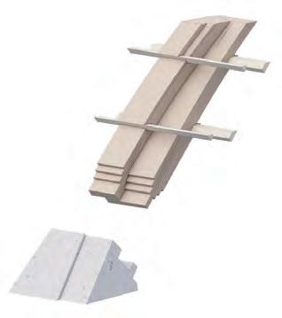
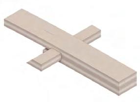
Node 01 : Joint for component#1 and #2
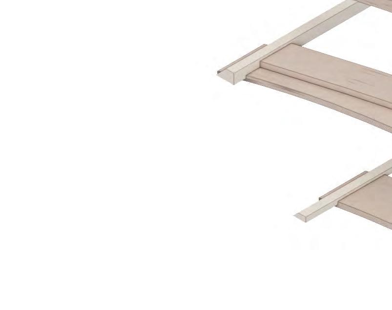
Node 02 : Joint for component #2 and #3
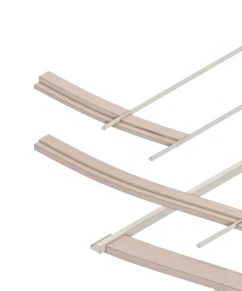
Node 03 : Joint for component #1 and #3 to roof rafters
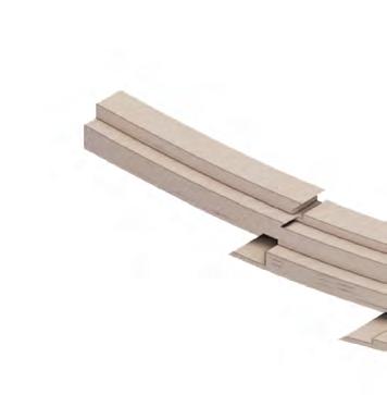
Node 04 : Joint of component #1 and #2 to groud
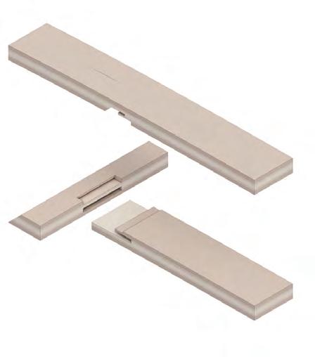
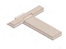
PRIMARY STRUCTURE JOINERY
The connection between the stacked column and cross beams uses simple interpretation of traditional Japanese mortise and tenon joinery detail.


67
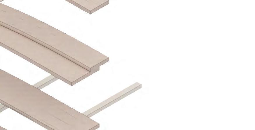
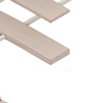
Stacked column layer 1
Stacked column layer 2
Cross beam
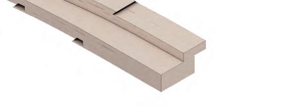
Stacked column to beam connection
4.7 DETAILED DEVELOPMENTSTRUCTURAL OPTIMISATION
Stacked column to beam second layer connection



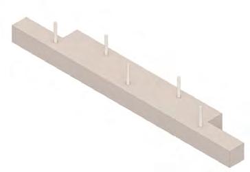
STACKING DETAIL
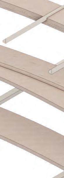
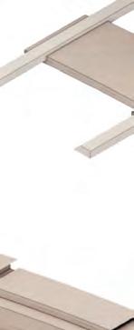
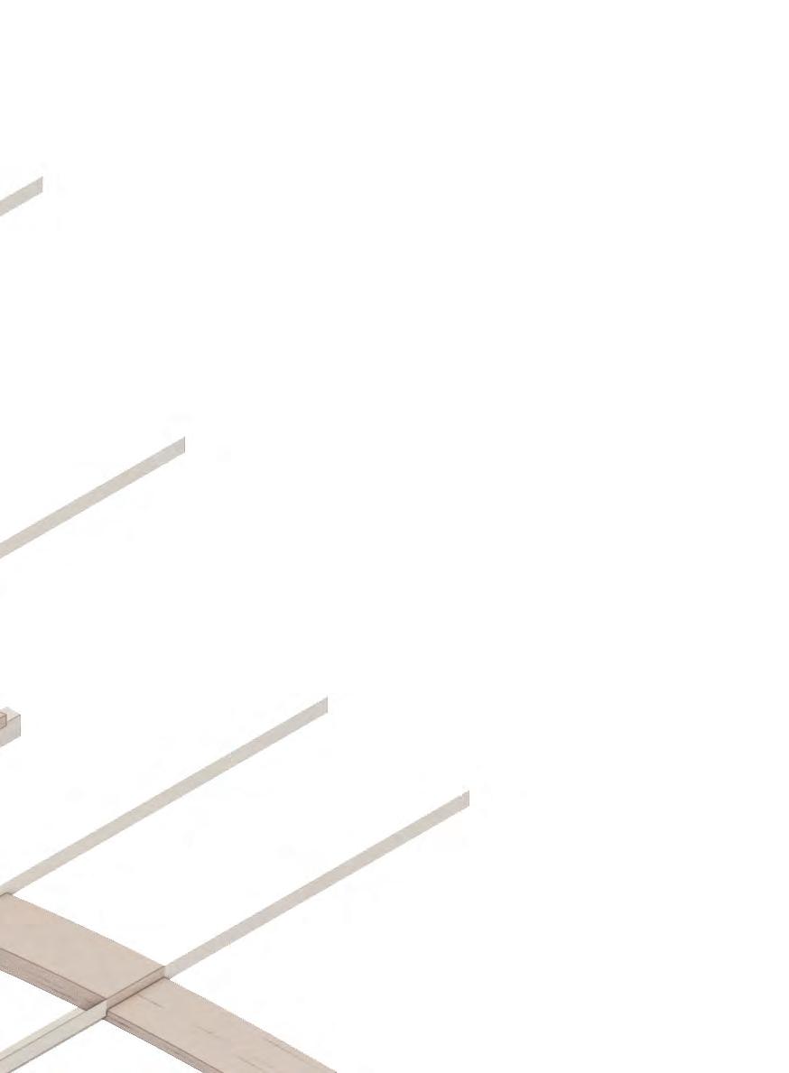
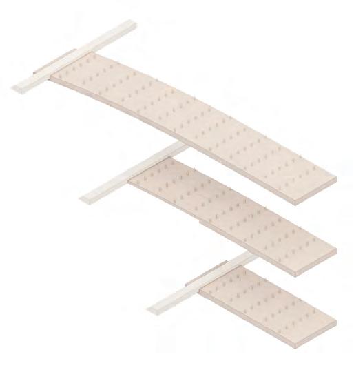
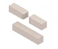
Each layer will incorporate finger joints to connect the individual members, while dowels will be employed to secure each layer together.
SECTION 4DETAIL DEVELOPMENT 68
300mm glue-laminated timber
300mm
1200mm
Finer ioints
Dowels assembly
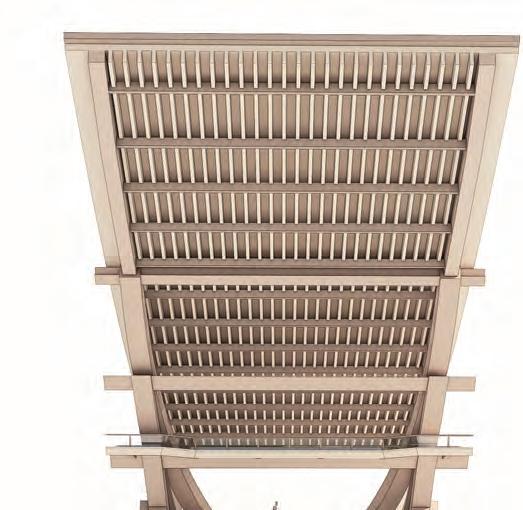
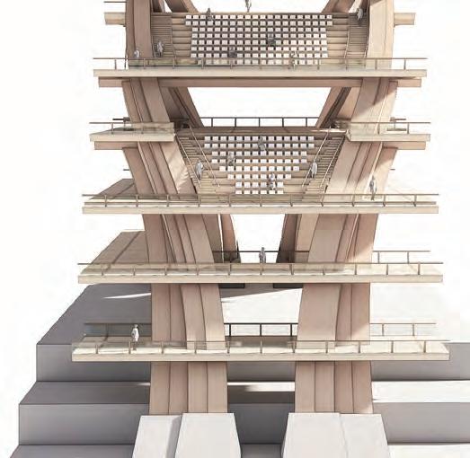
SEATING ARRANGEMENT
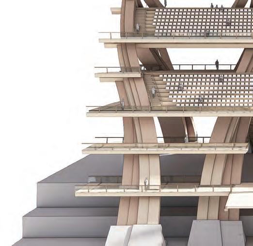
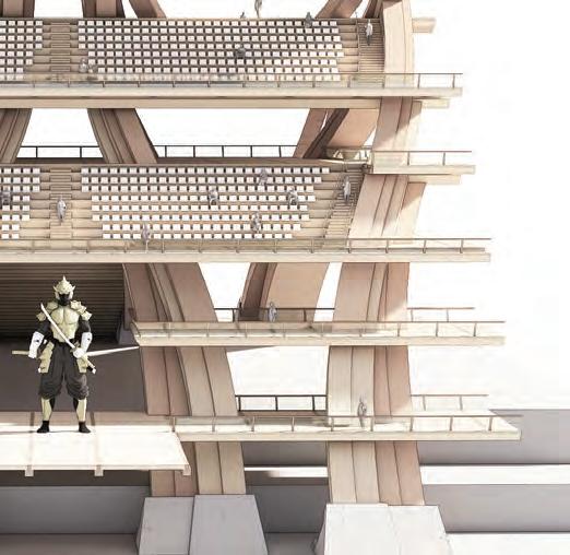
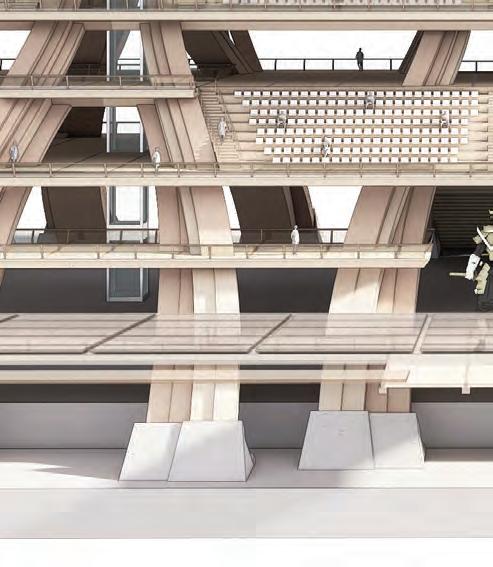
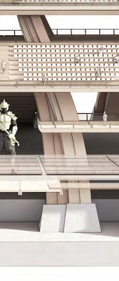
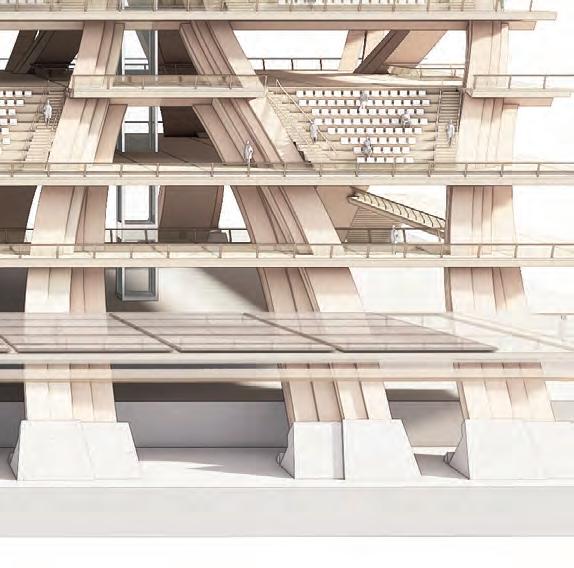
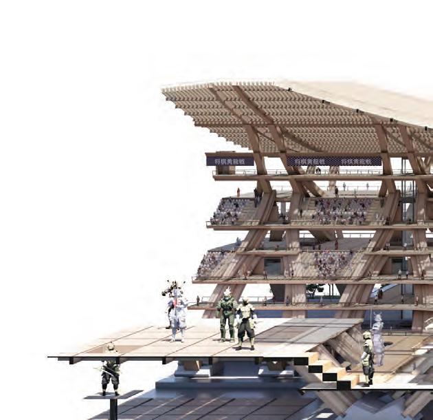
The developed structure features two levels of seating stands positioned above the stage, which may be accessed from both levels in between.
69 4.8 DETAILED DEVELOPMENTSTRUCTURAL AGGREGATION - AXIS I
Seating level 1
Seating level 2
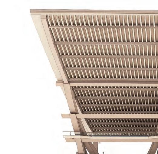

EXTENDED SEATING ARRANGEMENT
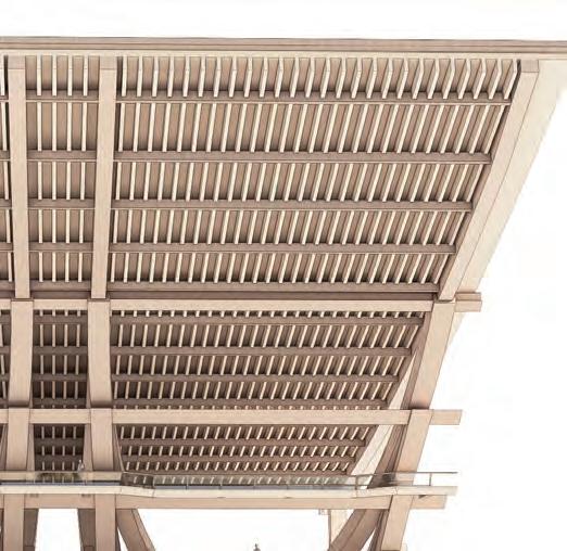
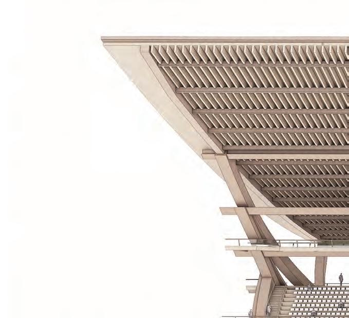
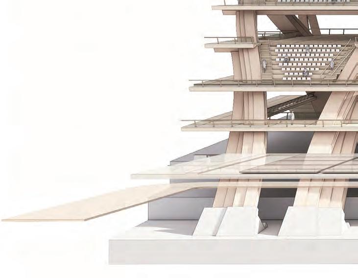
The extended seating arrangement is formed by combining two modules of the structure, with the primary component pushed backwards to support the extended part.
SECTION 4DETAIL DEVELOPMENT 70
Shifting primary structure supporting extended seating
71 4.8 DETAILED DEVELOPMENTSTRUCTURAL AGGREGATION - AXIS I

Stage level
SYSTEM AGGREGATION - AXIS I
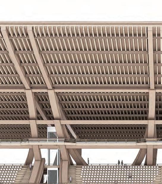
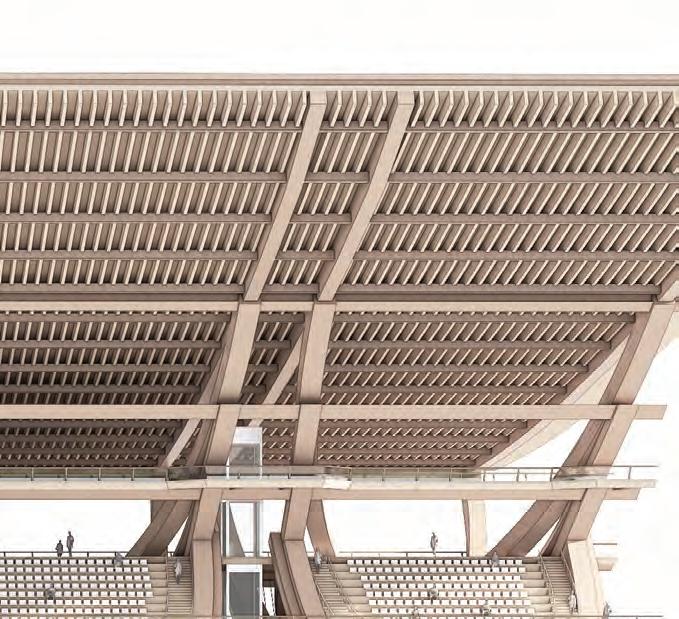
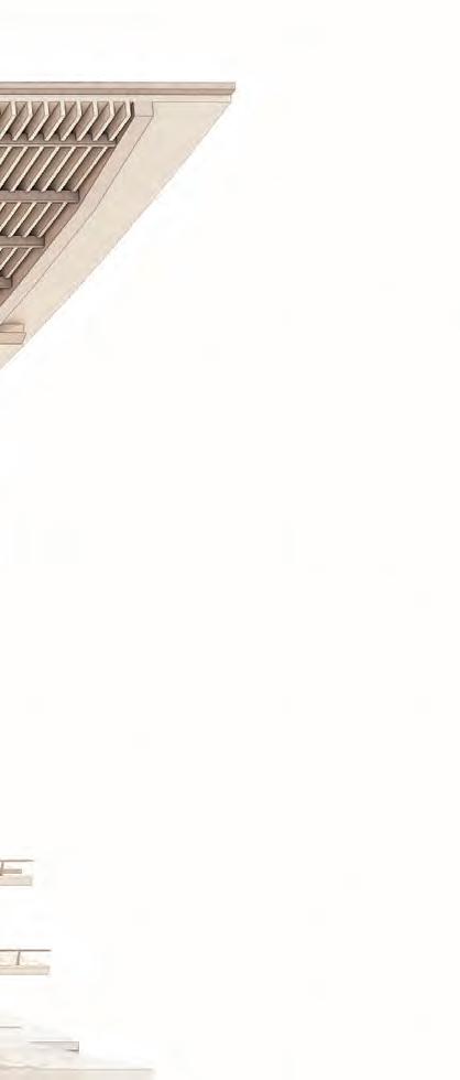
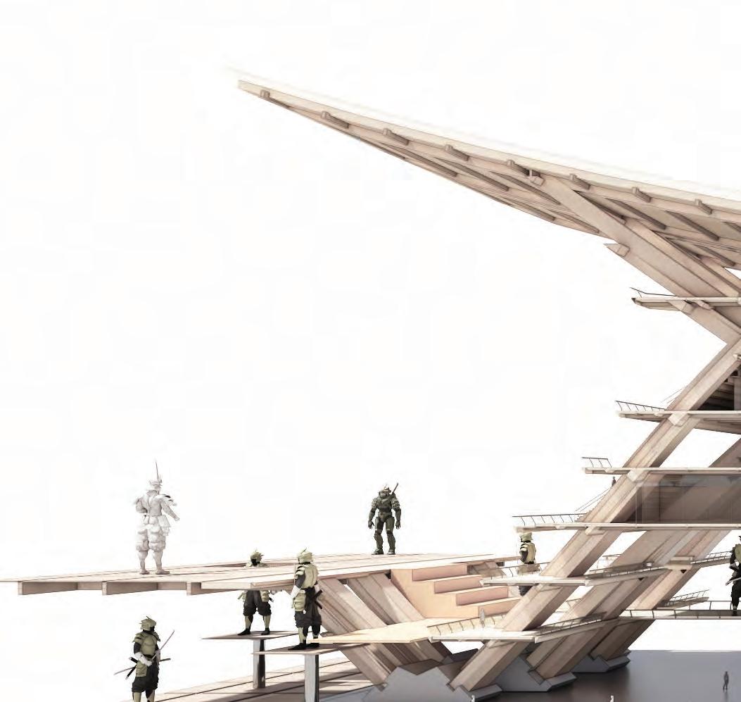
Combining four modules will enable the stage to be positioned, while creating a larger platform area where additional programmes can be incorporated. This demonstrates both the configuration of individual seating modules and the expanded seating version, which offers greater diversity and segmentation of the seating areas.
SECTION 4DETAIL DEVELOPMENT 72


73 4.9 DETAILED DEVELOPMENTSTRUCTURAL AGGREGATION - AXIS II

SYSTEM AGGREGATION - AXIS II
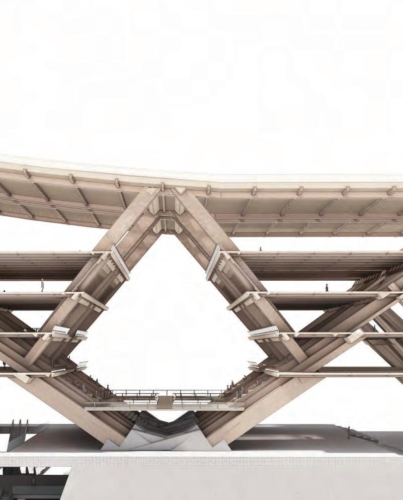
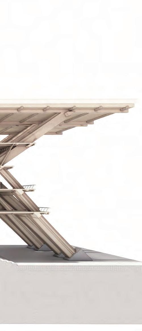
This illustrates the structural system’s versatility by showing how it may be scaled up or down to accommodate different roof slopes. Additionally, the aggregated system generates spatial opportunities, leading to the formation of an atrium space between the two sides.
SECTION 4DETAIL DEVELOPMENT 74
75 4.10 DETAILED DEVELOPMENTVERTICAL CIRCULATION

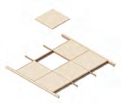
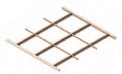
Secondary beams and floor grid system
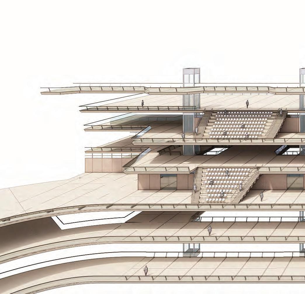
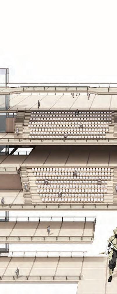
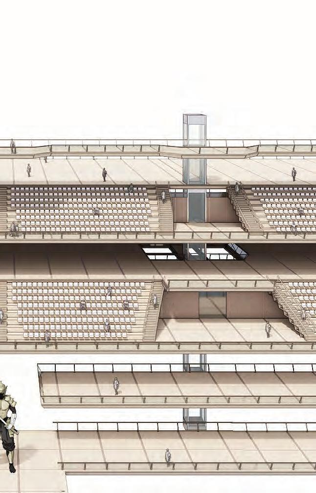
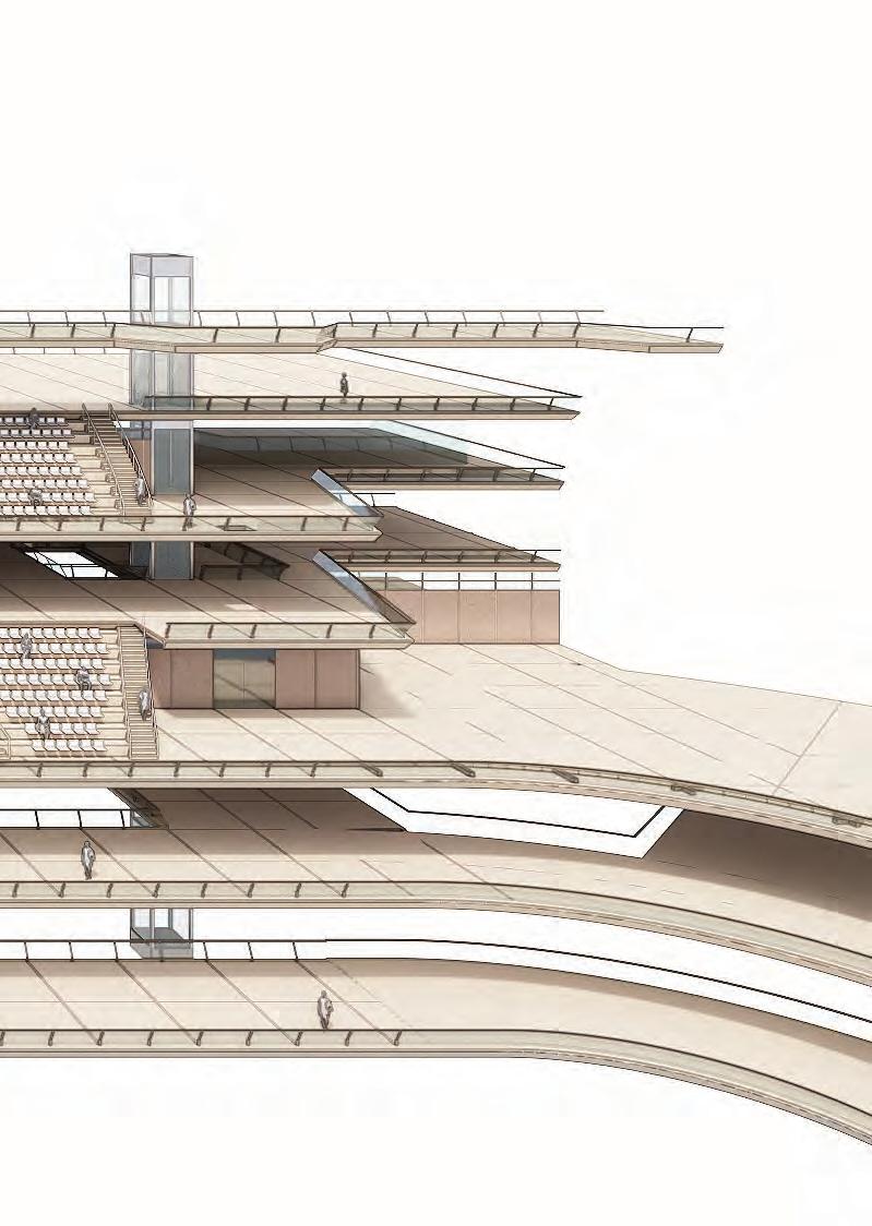
VERTICAL CIRCULATION INTEGRATION
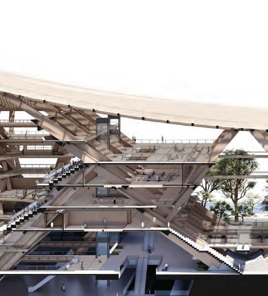
The structural system incorporates vertical circulation that spans from the lower to the upper floors, using the floor system’s integration at each 23-meter interval on both sides.
SECTION 4DETAIL DEVELOPMENT 76
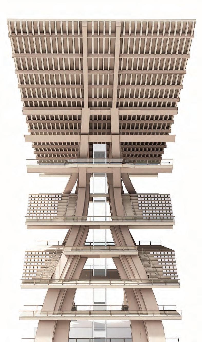
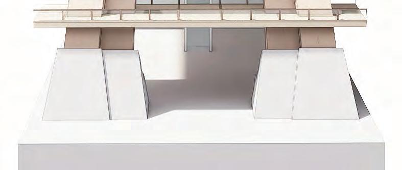
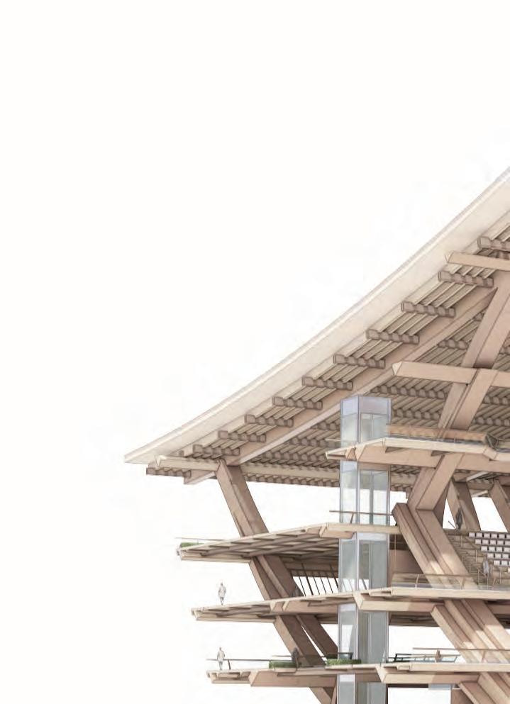
VERTICAL CIRCULATION FRAGMENT
The location of vertical circuation adheres to the morphology of the primary structural framework as an architectural language.
77 4.11 DETAILED DEVELOPMENTFRAGMENTS


TYPICAL FRAGMENT
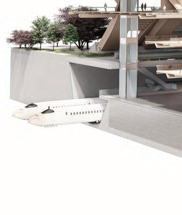
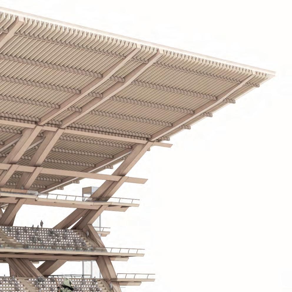
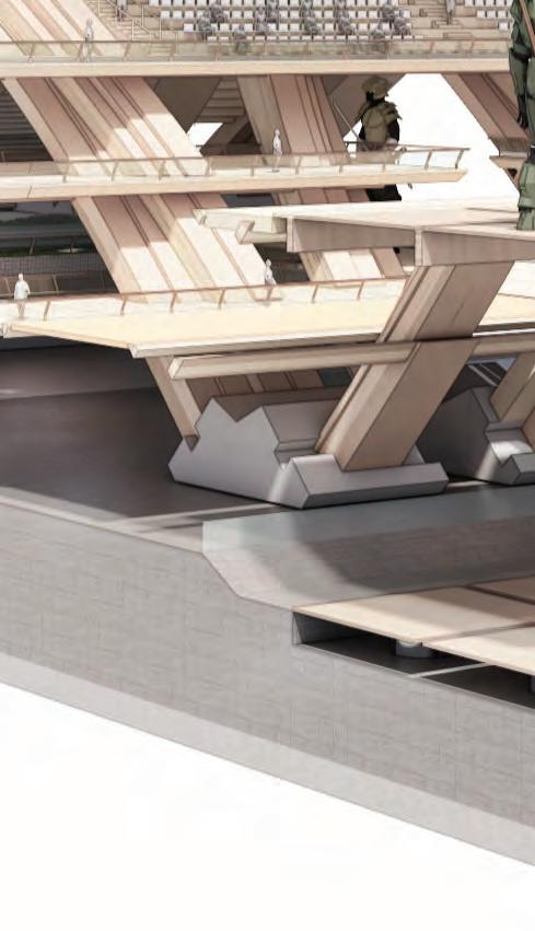
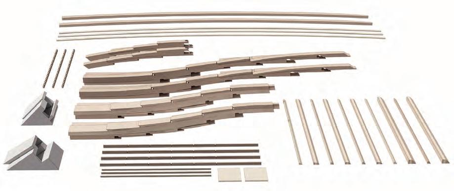
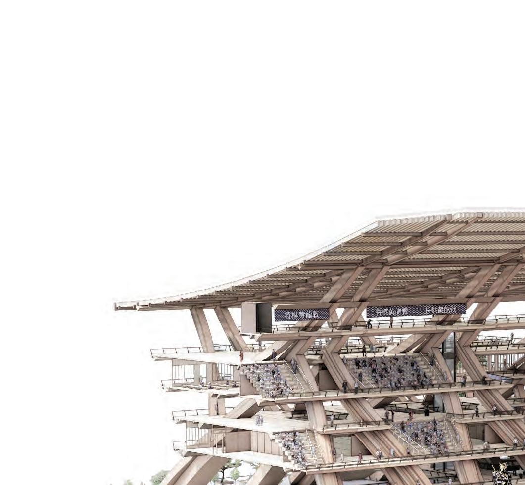
The typical fragment depicts the state and interconnection of the surrounding park conditions, transit system, and the mind-sport robotics stage.

SECTION 4DETAIL DEVELOPMENT 78
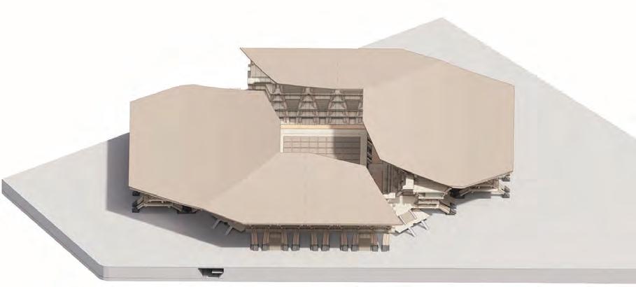


79
4.
3. Secondary structures and floor panels installation
Roof structures installation
5. Roof panels installation
2. Primary structures installation
Roof
Roof
Primary component #3 Primary component #2 Primary component #1
1. Site preparation and plinths installation
rafter Roof beams
purlin
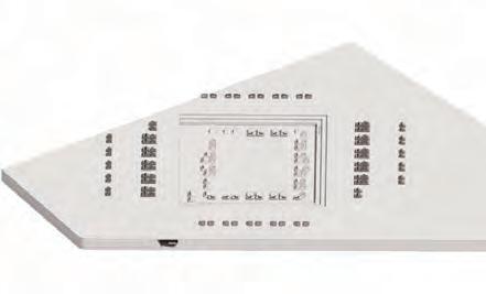
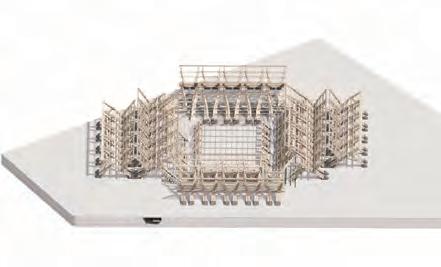
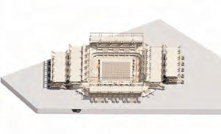
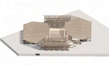
4.12 DETAILED DEVELOPMENTPREFABRICATION AND CONSTRUCTION
Concrete plinthFloor panelCross beam
Slab
joist Secondary beam
OPEN SPACE
> Viewing platform
> Food centre
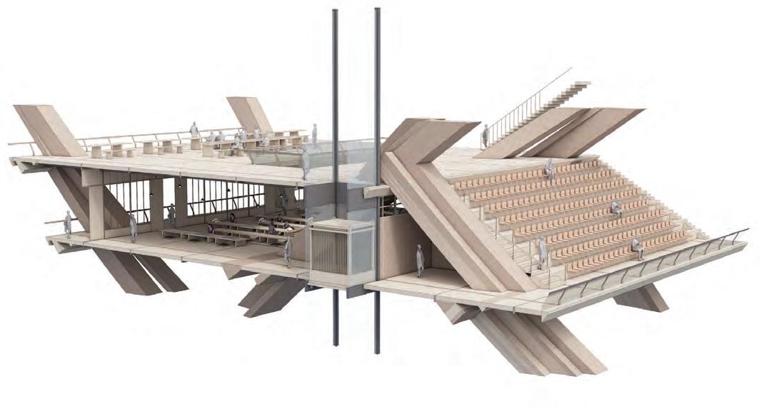
ENCLOSED SPACE
> Educational training centre
TYPICAL FRAGMENT
OPEN SPACE
> Viewing platform
> Food centre
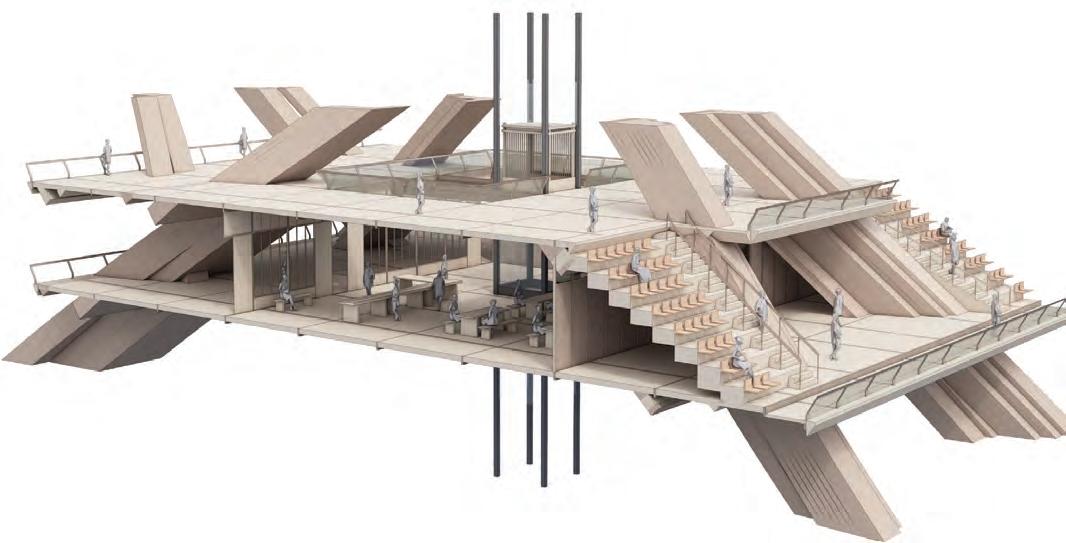
ENCLOSED SPACE
> Reception/ Ticketing area
IN BETWEEN FRAGMENT
SPATIAL TYPOLOGIES
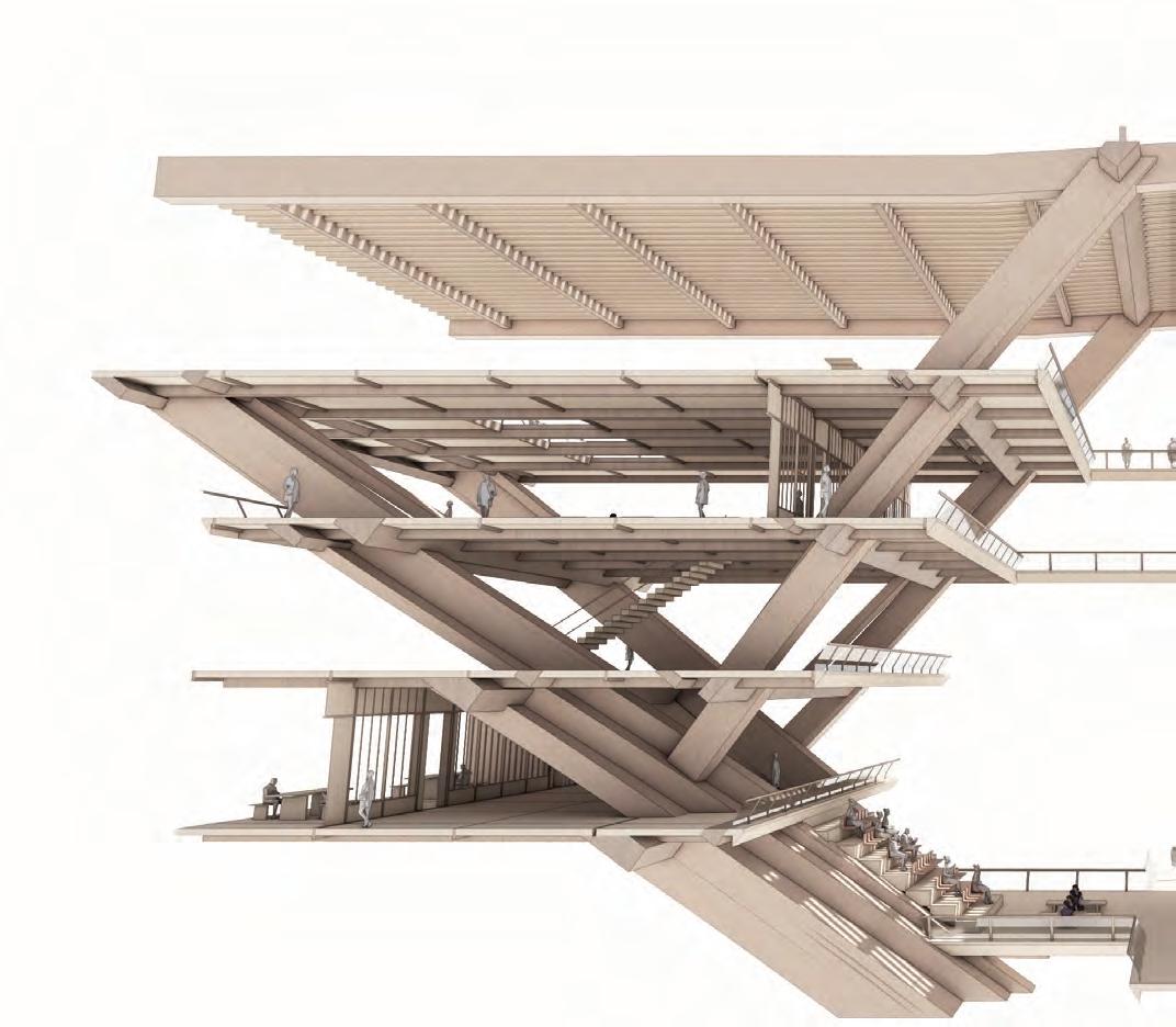
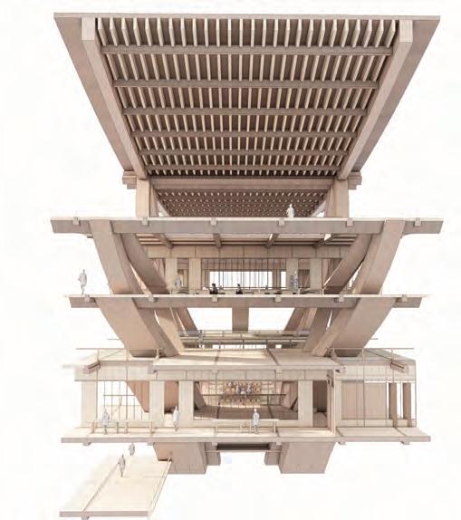
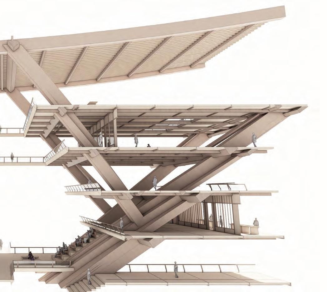
Enclosed spaces are created behind the seating stands to accommodate the ticketing area and educational centre. The platform on the upper and lower levels of the stand will be an open place for retail and observation.
SECTION 4DETAIL DEVELOPMENT 80
4.13 DETAILED DEVELOPMENTSPATIAL TYPOLOGIES
Roadside Connecting bridge Connecting bridge
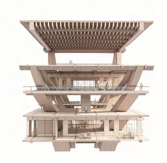
81
Road side
Atri prome 4.13 DETAILED DEVELOPMENTSPATIAL TYPOLOGIES - ATRIUM
SECTION 4 DETAIL DEVELOPMENT 82 ium enade
Stage side
Stage side
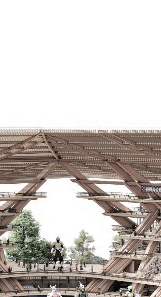
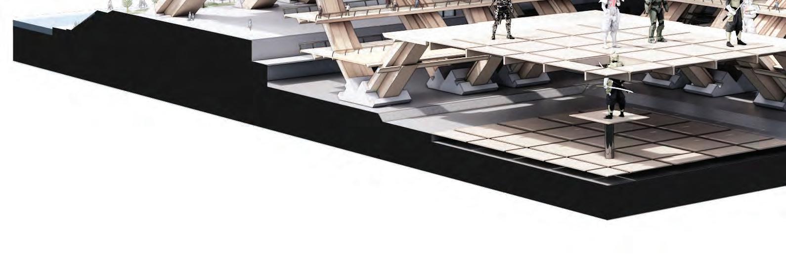
83 4.14 DETAILED DEVELOPMENTSECTIONAL FRAGMENT

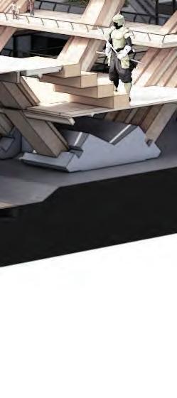
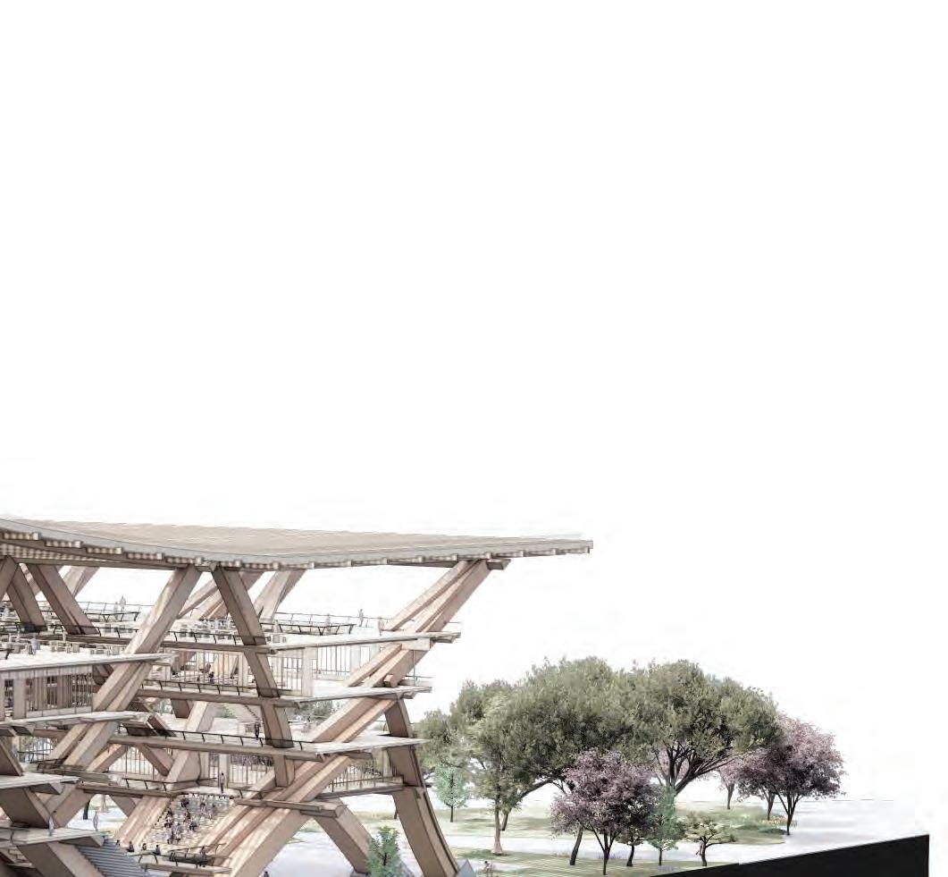
SECTION 4DETAIL DEVELOPMENT 84
85
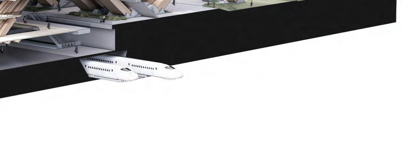
Train to the city centre
4.14 DETAILED DEVELOPMENTSECTIONAL FRAGMENT
Main robotics stage



SECTION 4DETAIL DEVELOPMENT 86
Entrance from the north side park


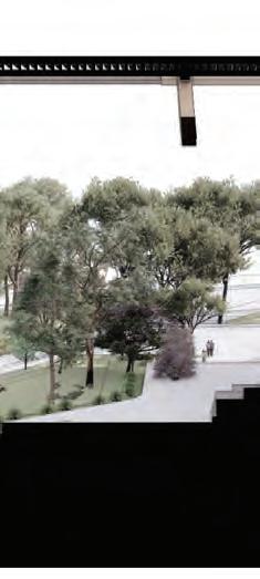


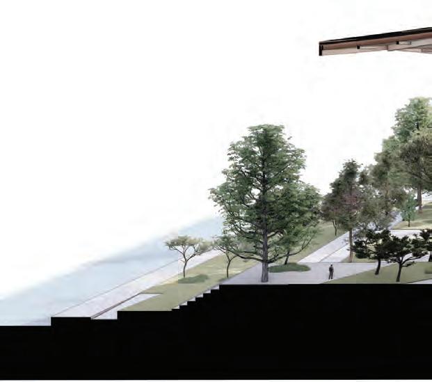
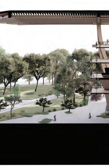
87 4.15 DETAILED DEVELOPMENTPROJECT KEY LEVELS
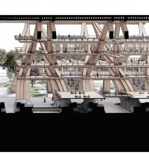
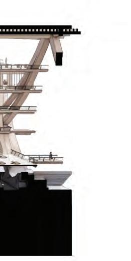
Connectivity with the elevated atrium promedane
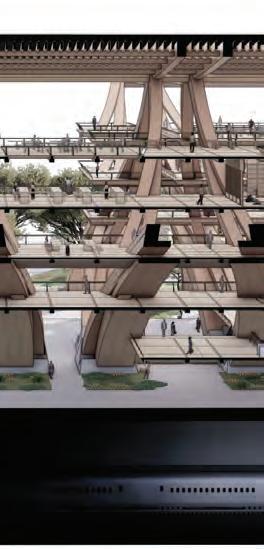
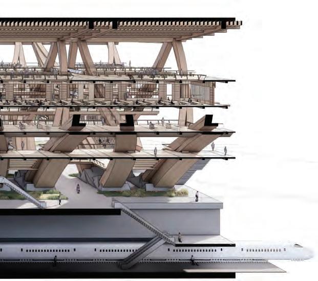
Connectivity with the transportation system
SECTION 4DETAIL DEVELOPMENT 88
underground ground floor first floor second floor FFL +0.0m FFL -10.0m FFL +4.5m FFL +9.0m FFL +13.5m FFL +18.0m FFL +22.5m FFL +0.0m FFL +4.5m FFL +9.0m FFL +13.5m FFL +18.0m FFL +22.5m third floor fourth floor fifth floor ground level mezzanine level first floor second floor third floor fourth floor
SECTION 5: FINAL DRAWINGS
05
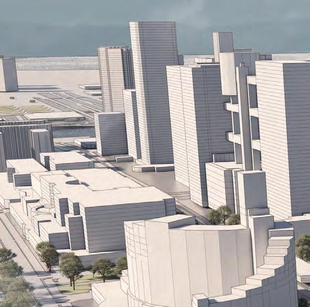
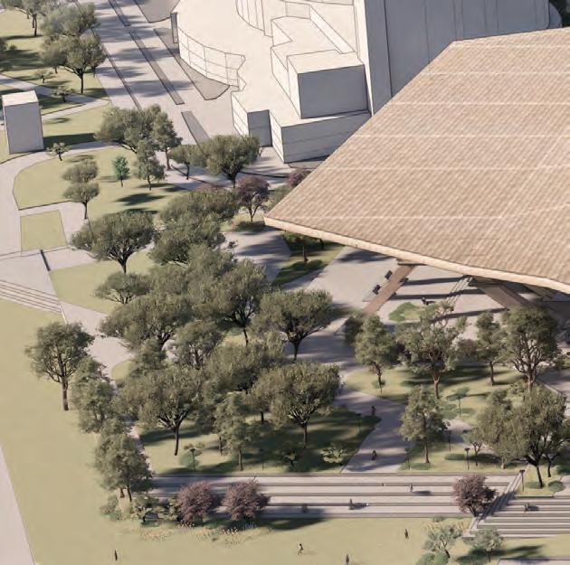
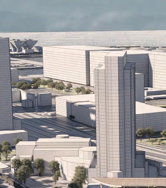
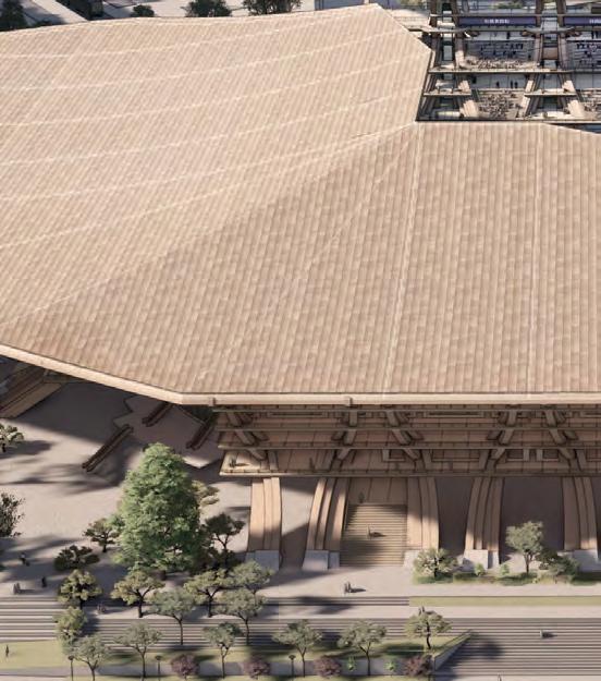
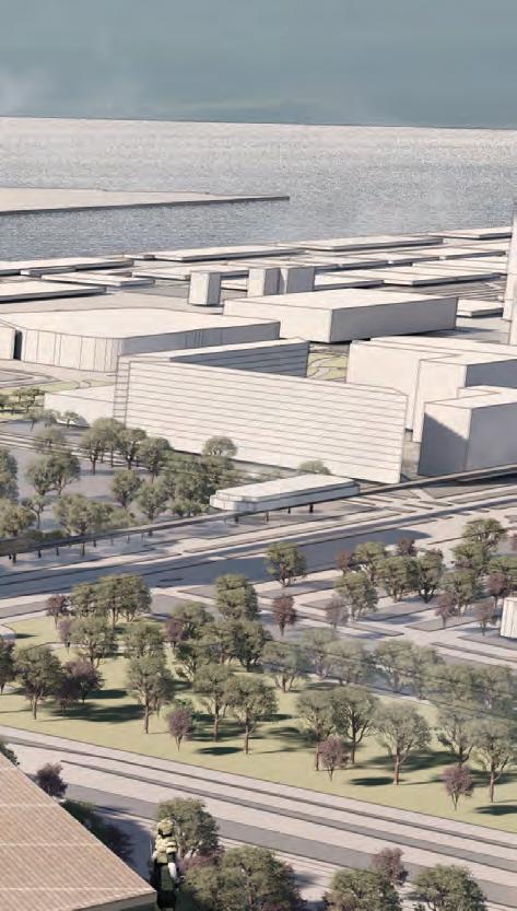
The design of the roof, with its axis-aligned opening showcases the seamless integration of significant infrastructure within the urban environment.
91 5.1 FINAL DRAWINGSAERIAL VIEW - GLOBAL SCHEME
URBAN STADIUM


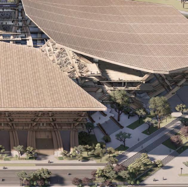


SECTION 5FINAL DRAWINGS 92 2



SEASIDE GRAND ENTRANCE
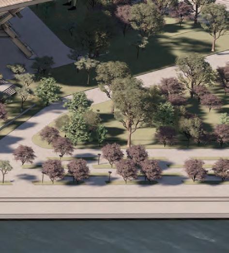
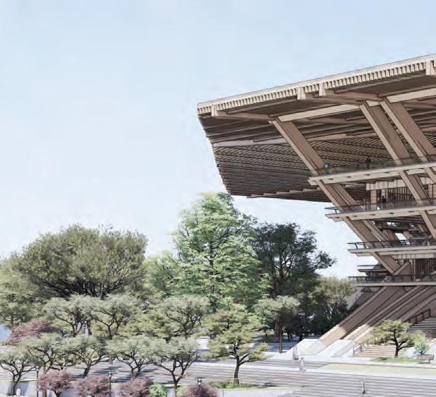
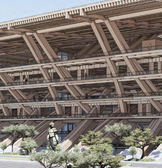
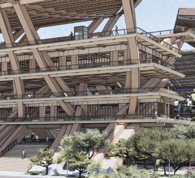
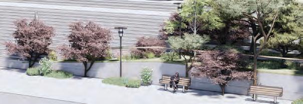
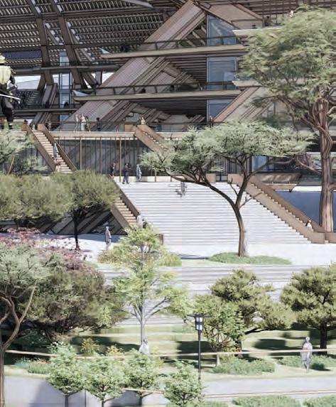
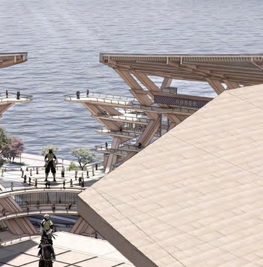
93 5.2 FINAL DRAWINGSEXTERIOR - WATERFRONT ACCESS
The seaside facade showcases the horizontal connection to its corner entrance, as well as the surrounding parks.




SECTION 5FINAL DRAWINGS 94 4
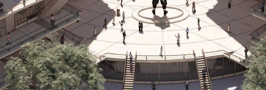
URBAN CONNECTIVITY


95 5.3 FINAL DRAWINGSEXTERIOR - URBAN SIDE ENTRANCE
The urban axis opening serves as a connection between the urban side and the seaside, linking both sides of the context.
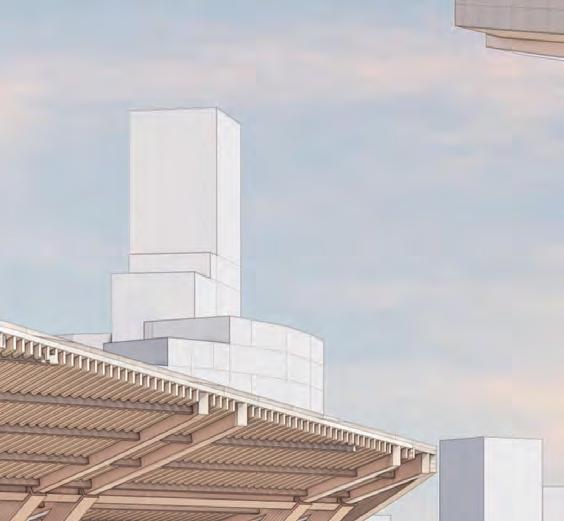
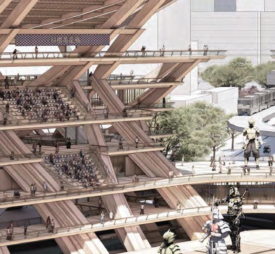
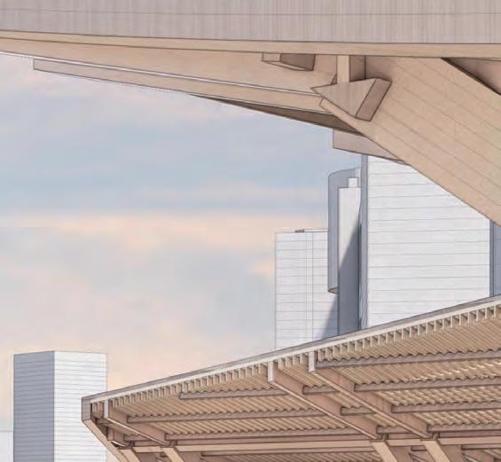



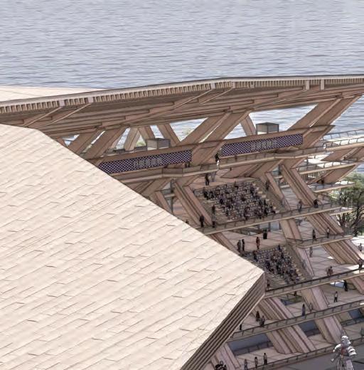
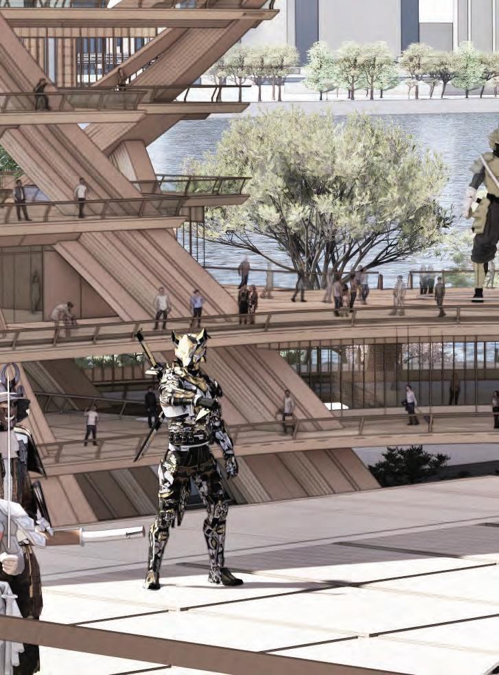
SECTION 5FINAL DRAWINGS 96 5.4 FINAL DRAWINGSINTERIOR - SEA SIDE OBSERVATORY
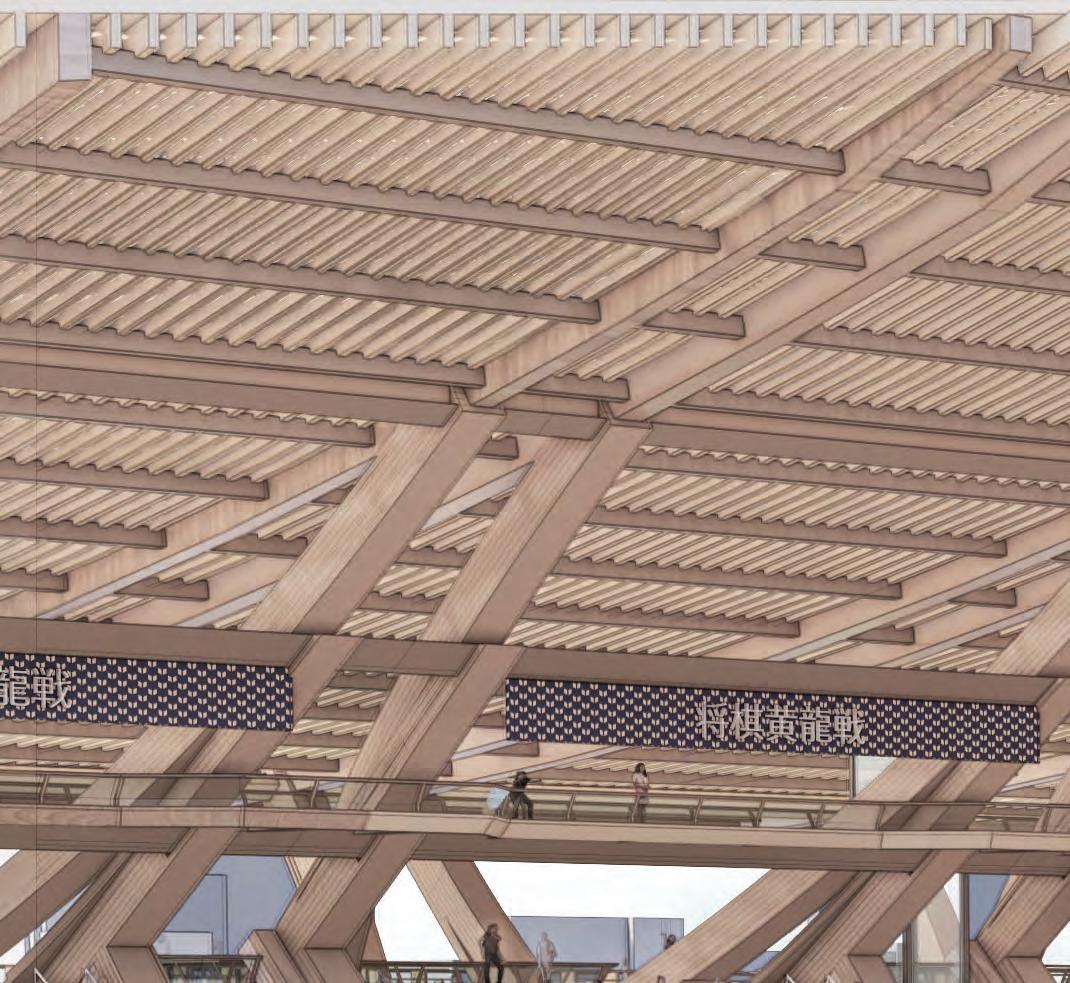
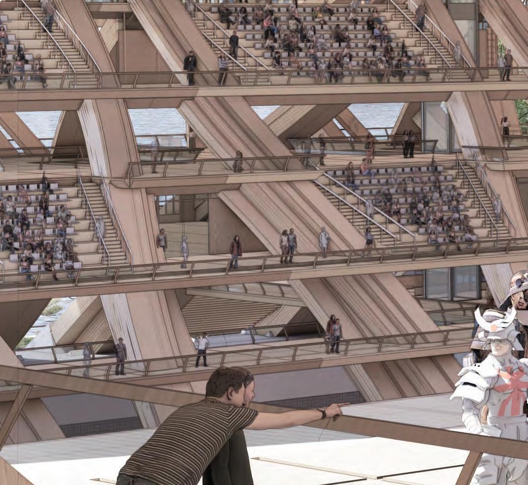
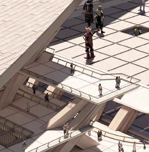
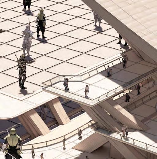
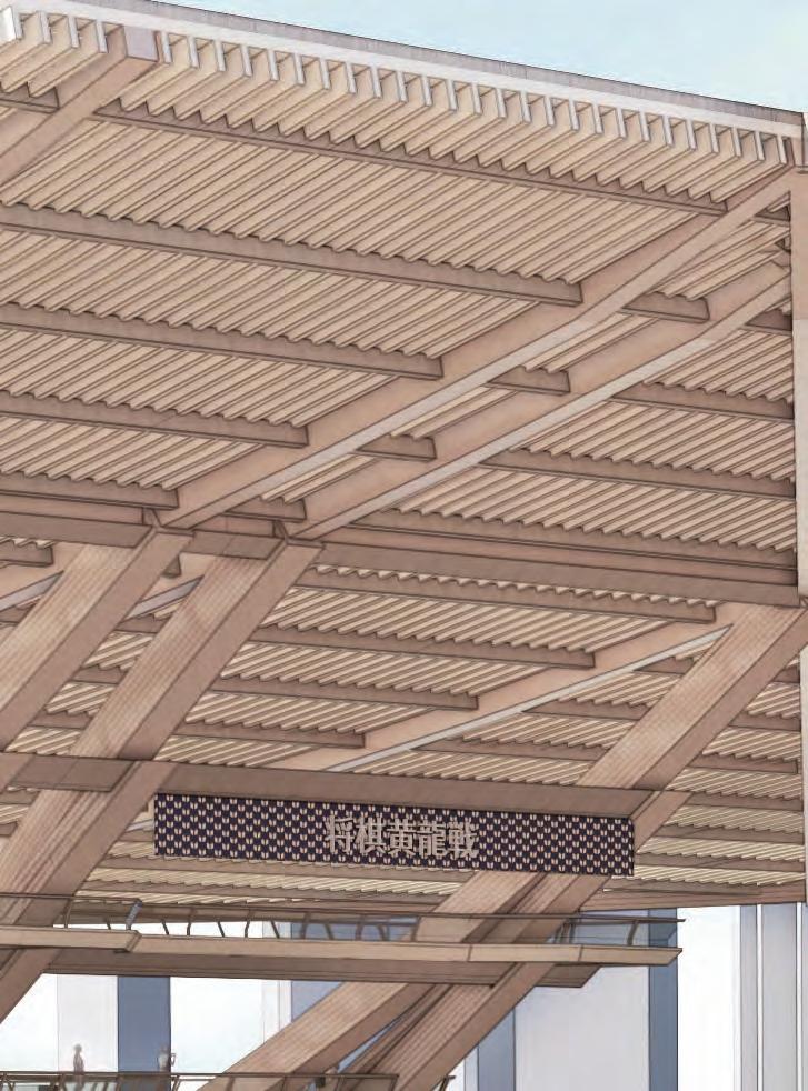
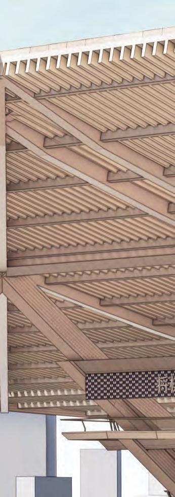
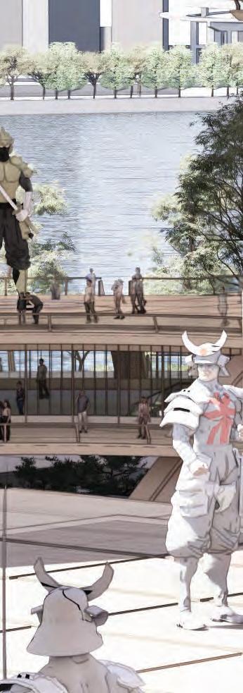
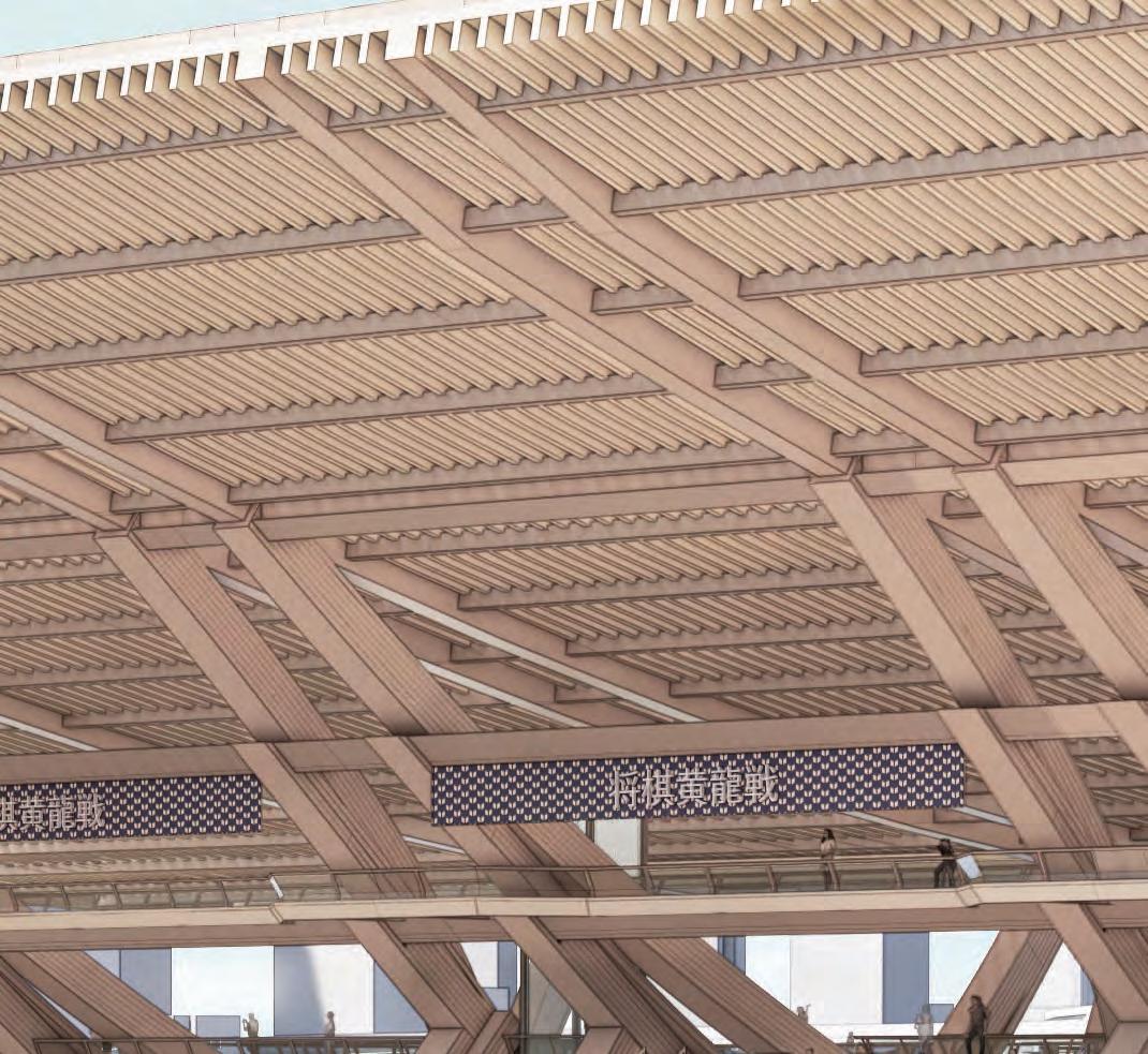
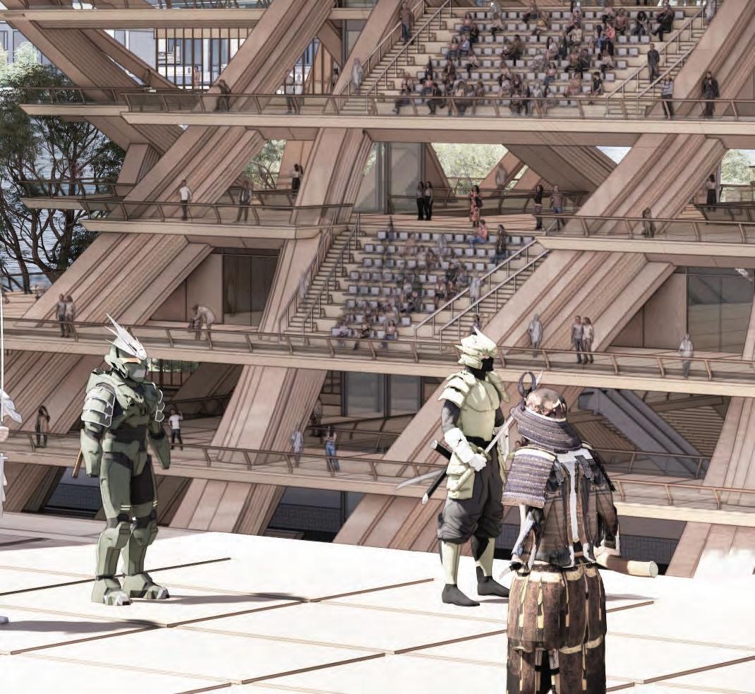
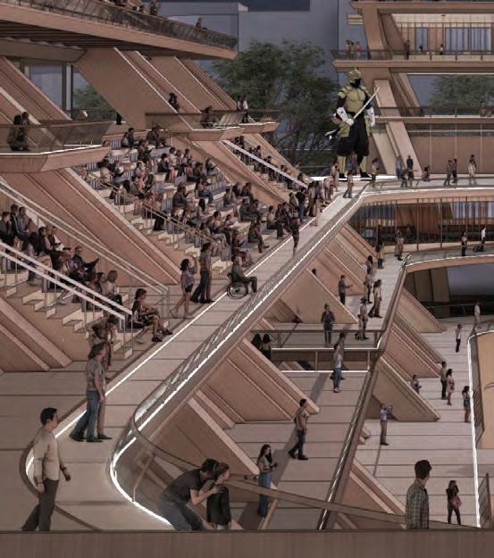
The corners of each wing function as robotics exhibition atriums, which are enclosed by the structural form and also act as circulation platforms to connect each wing.
97 5.5 FINAL DRAWINGSINTERIOR - CONER DISPLAY ZONE
ROBOTICS DISPLAY ATRIUM


SECTION 5FINAL DRAWINGS 98
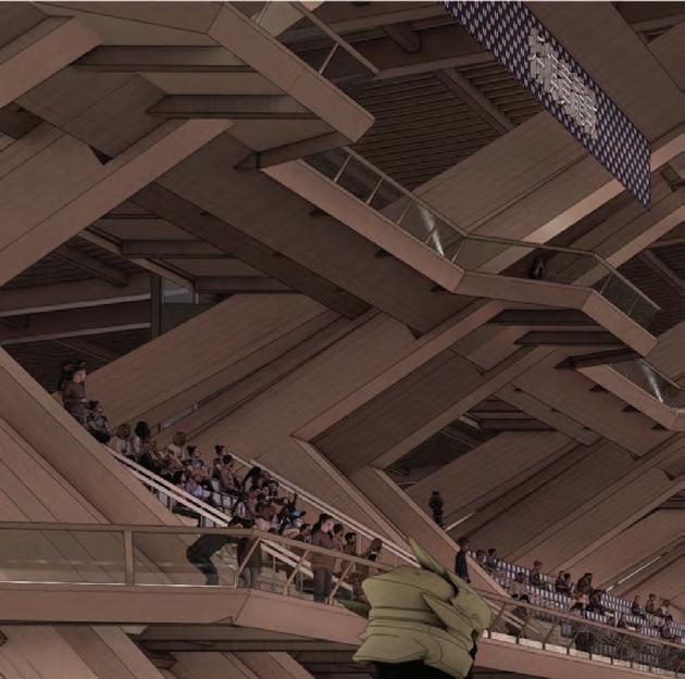
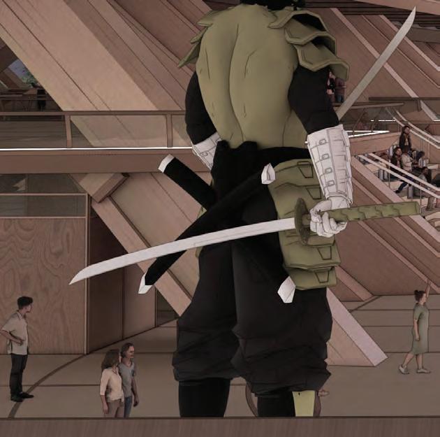
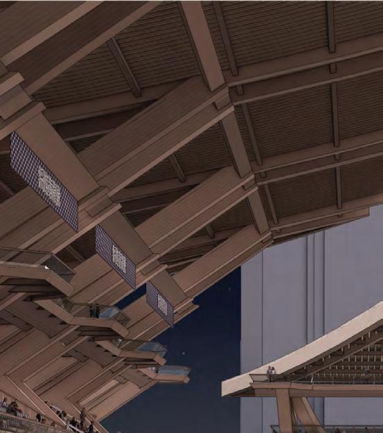
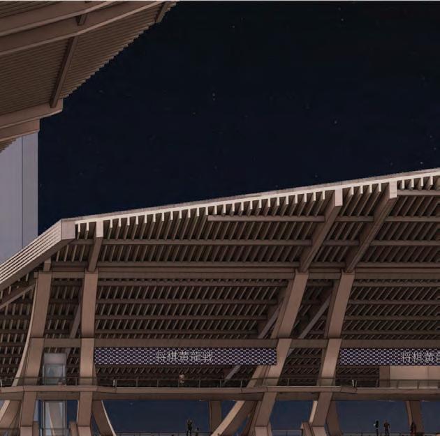
NIGHT TIME PLAY
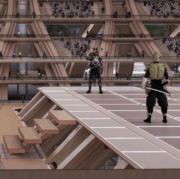
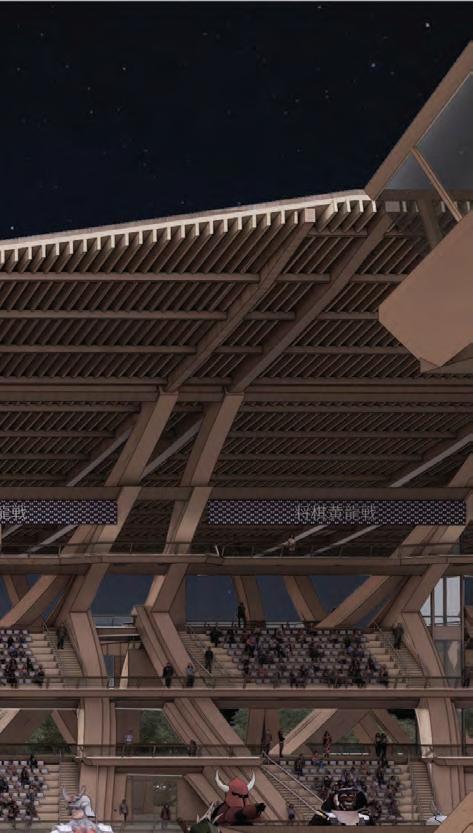
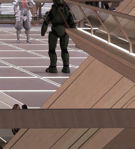
99 5.6 FINAL DRAWINGSINTERIOR - ROBOTICS PLAY
Mind-sport play scene at night from the corner, highting the continous platform where audiences can circulate around.




SECTION 5FINAL DRAWINGS 100
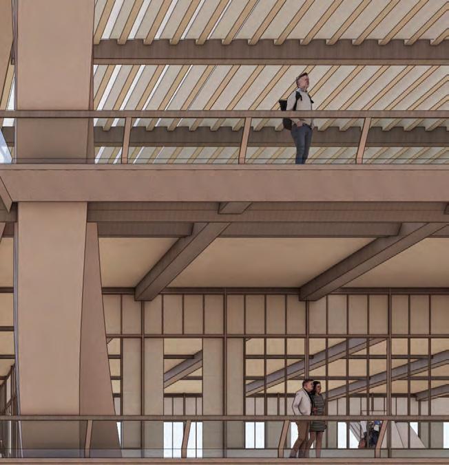
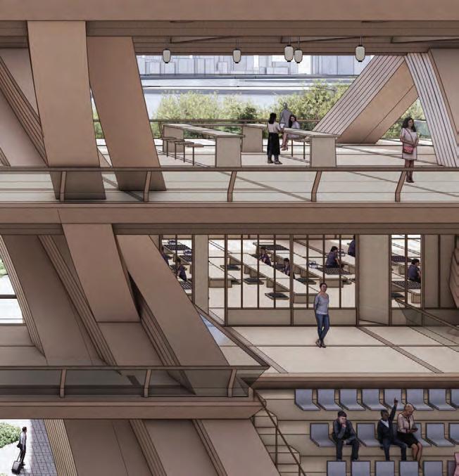
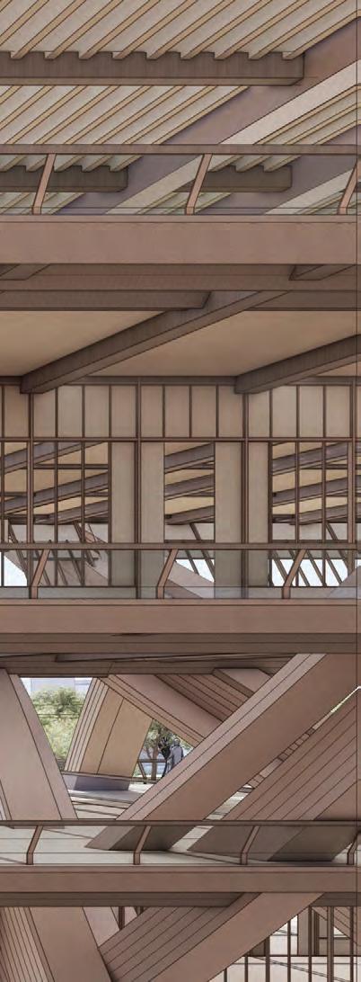
OBSERVATORY
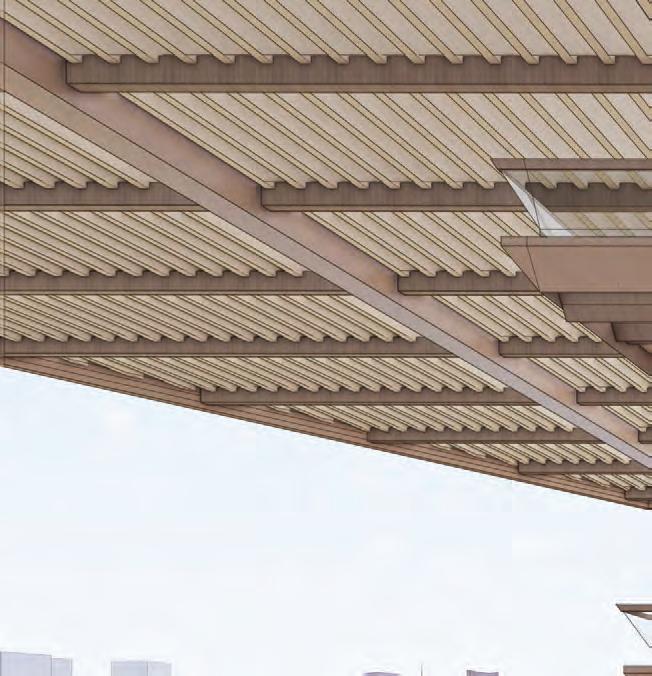
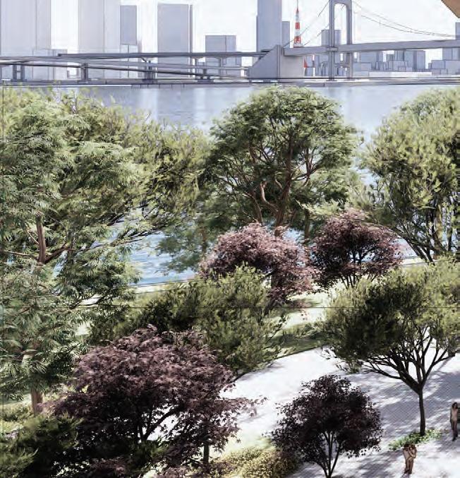
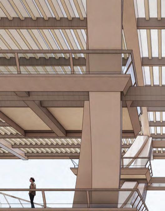
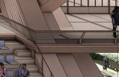
Located at the intersection of the educational cluster, just opposite the atrium space, is an observatory that offers an exquisite view of the rainbow bridge and the coastal park underneath.
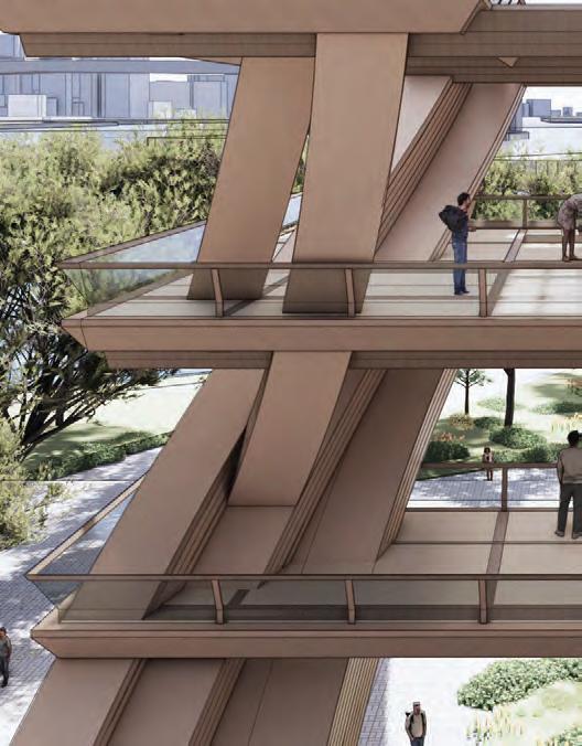
101 5.7 FINAL DRAWINGSINTERIOR - OBSERVATORY CORNER



SECTION 5FINAL DRAWINGS 102 2
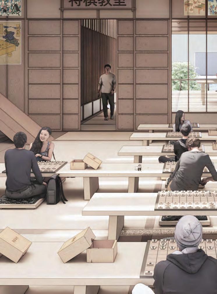
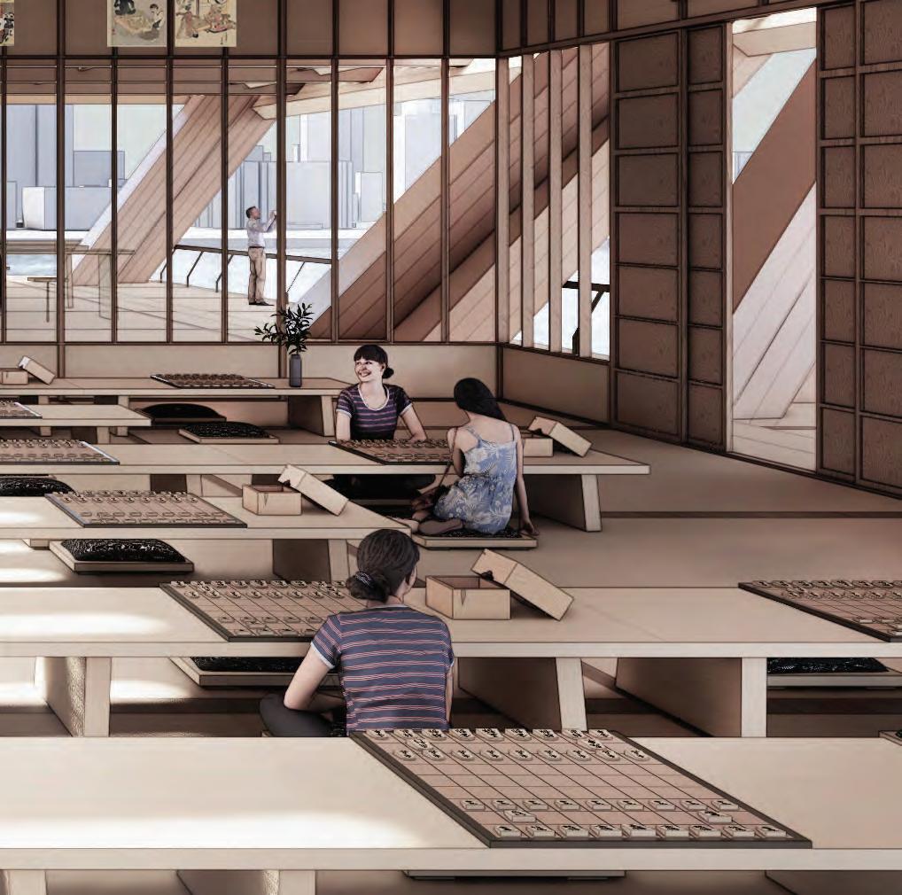
EDUCATIONAL CENTRE
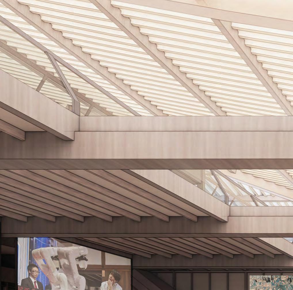
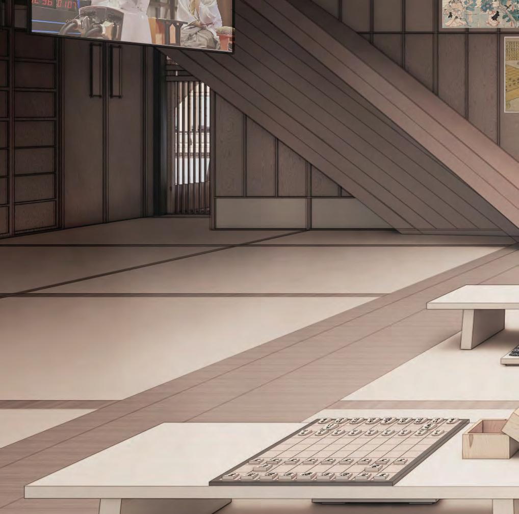
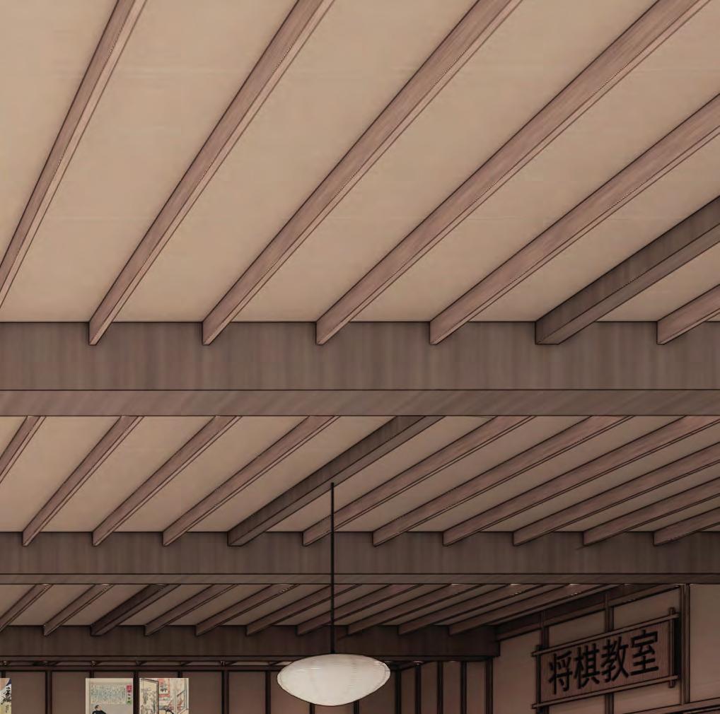
Located at the back end of the robotics stage, there is a grouping of enclosed educational centres where individuals can engage in the practice of shogi. These centres are organised into clusters based on skill level.
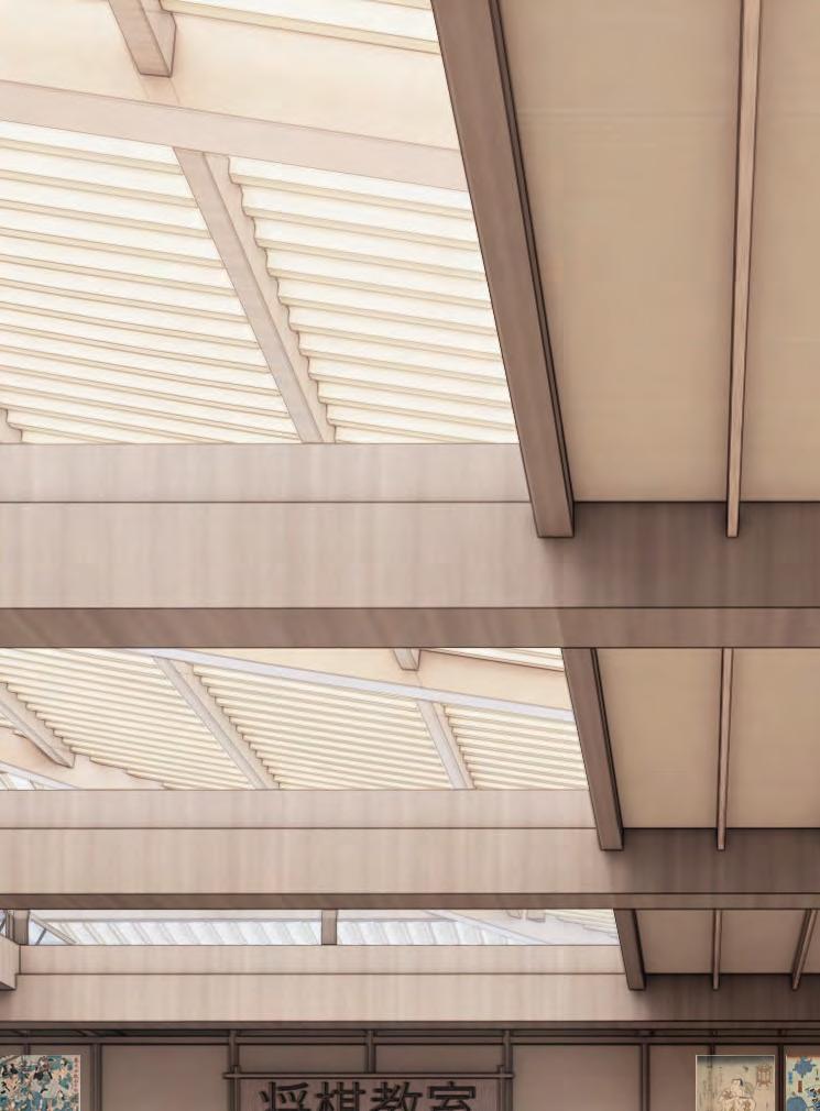
103 5.8 FINAL DRAWINGSINTERIOR - EDUCATIONAL CENTRE




SECTION 5FINAL DRAWINGS 104 4

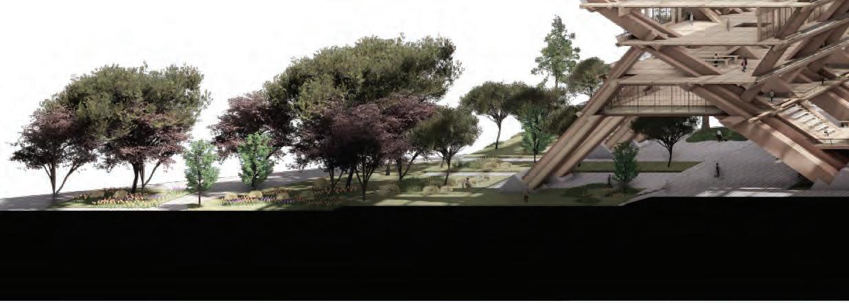
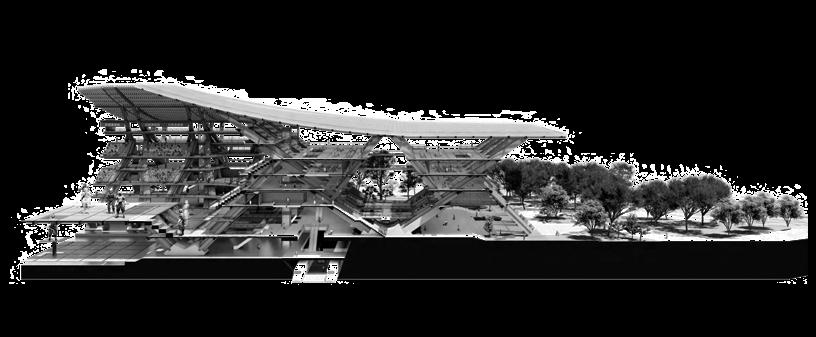
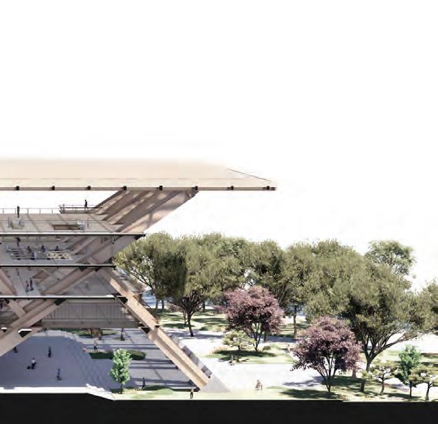
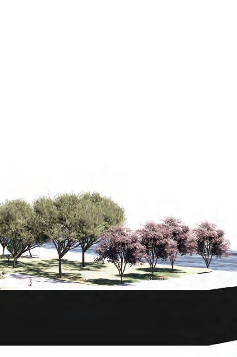
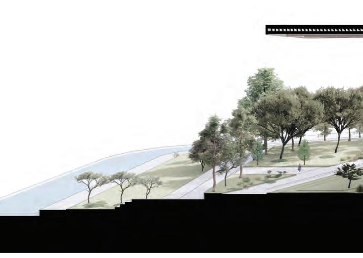
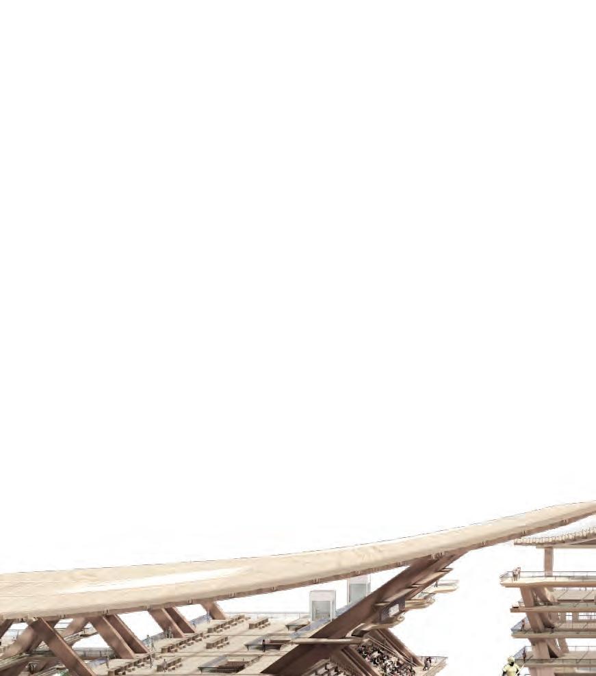
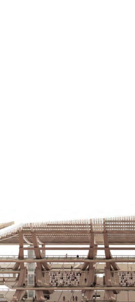
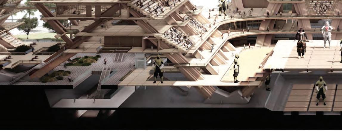
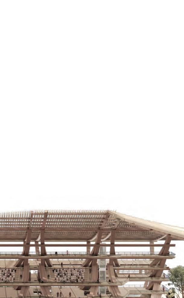
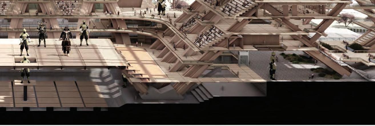
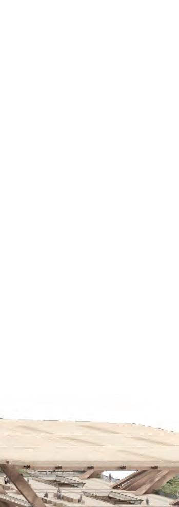
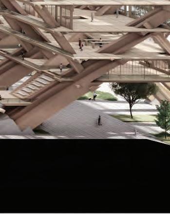
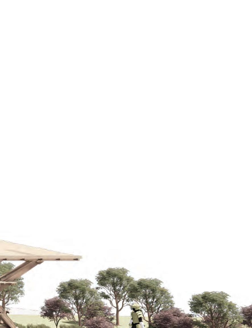
SECTIONAL PERSPECTIVE
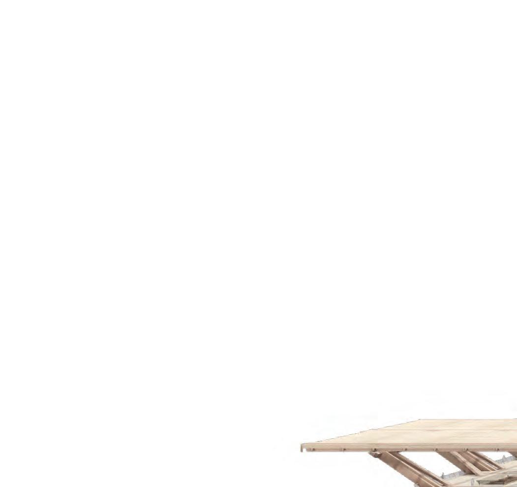
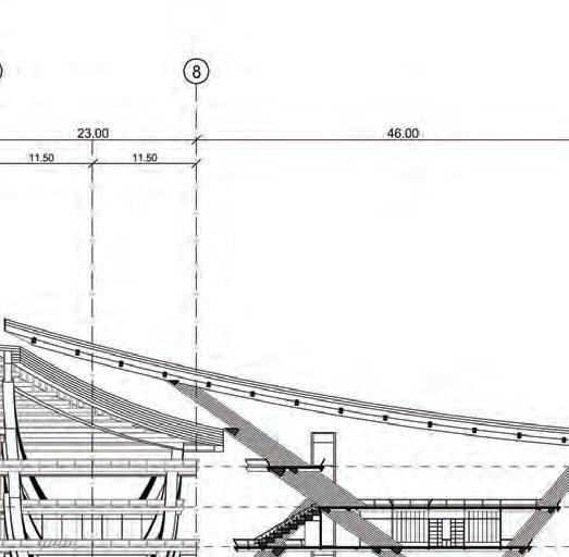
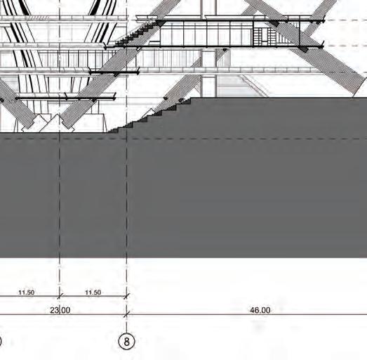
A sectional perspective view highlights the overall building spatial sequence from the parks and the enclosed clusters at different levels.
5.9 FINAL DRAWINGSPERSPECTIVE SECTION
105



SECTION 5FINAL DRAWINGS 106 06
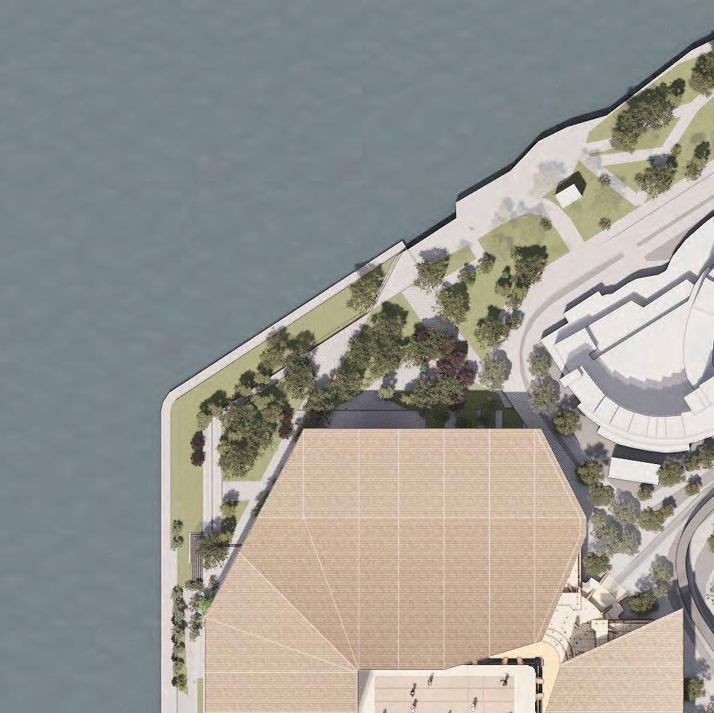
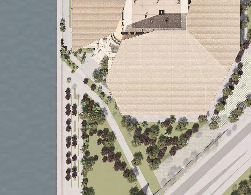

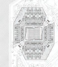
107 5.10 FINAL DRAWINGSSITE PLAN 1:1000 @ A3 L03 PLAN
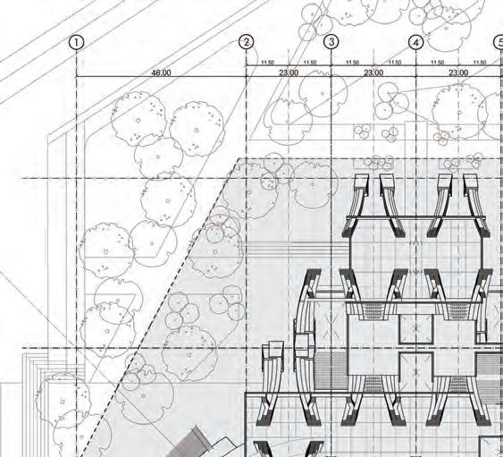
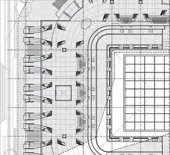
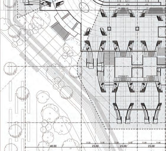
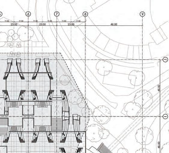
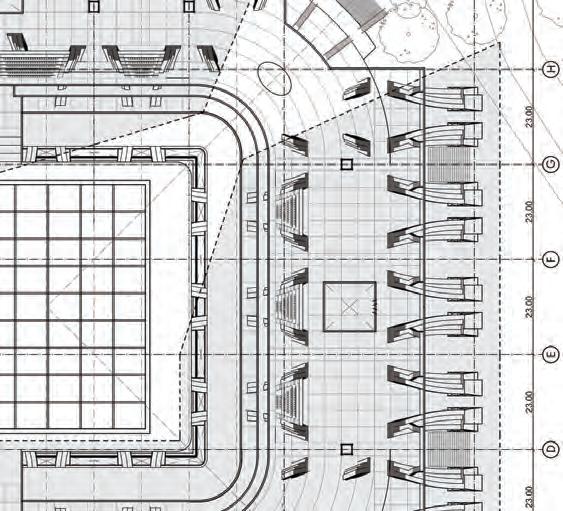
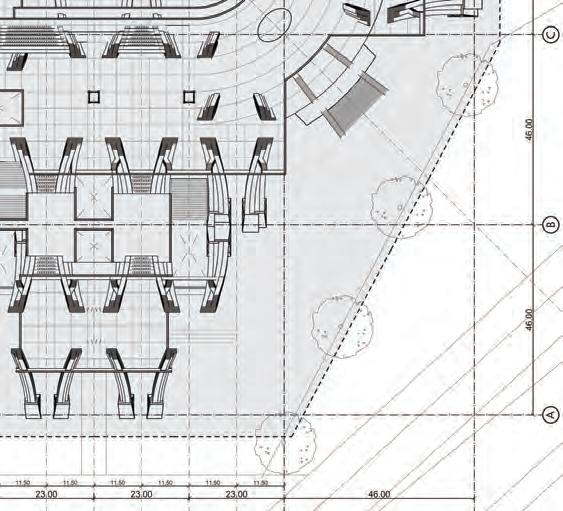
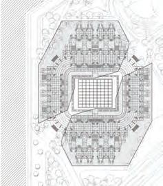
SECTION 5FINAL DRAWINGS 108 1:1000 @ A3 L03 PLAN 5.11 FINAL DRAWINGSFLOOR PLAN 1. SHOGI BOARD 2. TAKEN AREA 3. STANDS 4. ATRIUM PROMENADE 5. EDUCATIONAL CENTRE 6. TICKETS AND INFORMATION 7. CORNER DISPLAY 8. CORNER ENTRANCE 1. 2. 4. 4. 4. 4. 5. 5. 5. 5. 3. 3. 3. 3. 3. 3. 3. 3. 6. 6. 6. 6. 6. 6. 7. 8. 8. 8. 8. 7. 7. 7. 6. 6. 2.
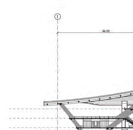
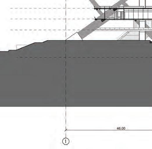
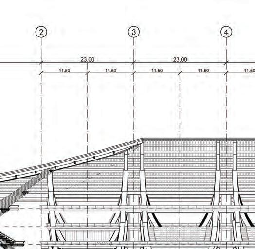
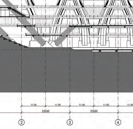


CROSS SECTION
1:500 @ A2
109 5.12 FINAL DRAWINGSCROSS SECTION
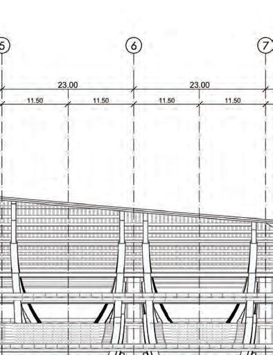
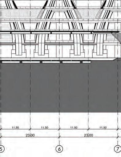



SECTION 5FINAL DRAWINGS 110
All work produced by Unit 14 Unit book design by Charlie Harriswww.bartlett.ucl.ac.uk/architecture
Copyright 2021 The Bartlett School of Architecture, UCL All rights reserved.
No part of this publication may be reproduced or transmited in any form or by any means, electronic or mechanical, including photocopy, recording or any information storage and retreival system without permission in writing from the publisher.


-

@unit14_ucl UNIT
CRAFTED HORIZONS 2024
At the center of Unit 14’s academic exploration lies Buckminster Fuller’s ideal of the ‘The Comprehensive Designer’, a master-builder that follows Renaissance principles and a holistic approach. Fuller referred to this ideal of the designer as somebody who is capable of comprehending the ‘integrateable significance’ of specialised findings and is able to realise and coordinate the commonwealth potentials of these discoveries while not disappearing into a career of expertise. Like Fuller, we are opportunists in search of new ideas and their benefits via architectural synthesis. As such Unit 14 is a test bed for exploration and innovation, examining the role of the architect in an environment of continuous change. We are in search of the new, leveraging technologies, workflows and modes of production seen in disciplines outside our own. We test ideas systematically by means of digital as well as physical drawings, models and prototypes. Our work evolves around technological speculation with a research-driven core, generating momentum through astute synthesis. Our propositions are ultimately made through the design of buildings and through the in-depth consideration of structural formation and tectonic. This, coupled with a strong research ethos, will generate new and unprecedented, one day viable and spectacular proposals. They will be beautiful because of their intelligence - extraordinary findings and the artful integration of those into architecture.
The focus of this year’s work evolves around the notion of ‘Crafted Horizons’. The term aims to highlight the architect’s fundamental agency and core competency of the profession to anticipate the future as the result of the highest degree of synthesis of the observed underlying principles. Constructional logic, spatial innovation, typological organisation, environmental and structural performance are all negotiated in a highly iterative process driven by intense architectural investigation. Through the deep understanding of constructional principles, we will generate highly developed architectural systems of unencountered intensity where spatial organisation arises as a result of sets of mutual interactions. Observation as well as re-examination of past and contemporary civilisatory developments will enable us to project near future scenarios and position ourselves as avant-garde in the process of designing a comprehensive vision for the forthcoming. The projects will take shape as research based, imaginative architectural visions driven by speculation.
Thanks to: ALA, Boele Architects, Daab Design, DaeWha Kang Design DKFS, Heatherwick, Knippershelbig, NK3, RSHP, Seth Stein Architects, ZHA, Expedition Engineering.



UNIT 14 @unit14_ucl
All work produced by Unit 14 Unit book design by Charlie Harriswww.bartlett.ucl.ac.uk/architecture Copyright 2021 The Bartlett School of Architecture, UCL All rights reserved.No part of this publication may be reproduced or transmitted in any form or by any means, electronic or mechanical, including photocopy, recording or any information storage and retreival system without permission in writing from the publisher.


