LHUENTSE SCHOOL OF CRAFTS -

MULJI -
4
UNIT Y4 KM
KISHAN
YEAR
@unit14_ucl
All work produced by Unit 14
-
www.bartlett.ucl.ac.uk/architecture
Copyright 2021
The Bartlett School of Architecture, UCL All rights reserved.

No part of this publication may be reproduced or transmitted in any form or by any means, electronic or mechanical, including photocopy, recording or any information storage and retrieval system without permission in writing from the publisher.

@unit14_ucl
 Cover design by Charlie Harris
LHUENTSE SCHOOL OF CRAFTS
 BHUTAN


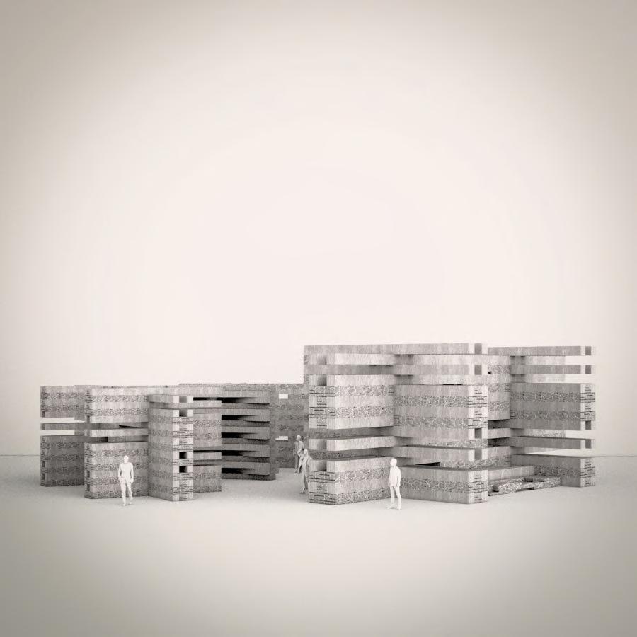
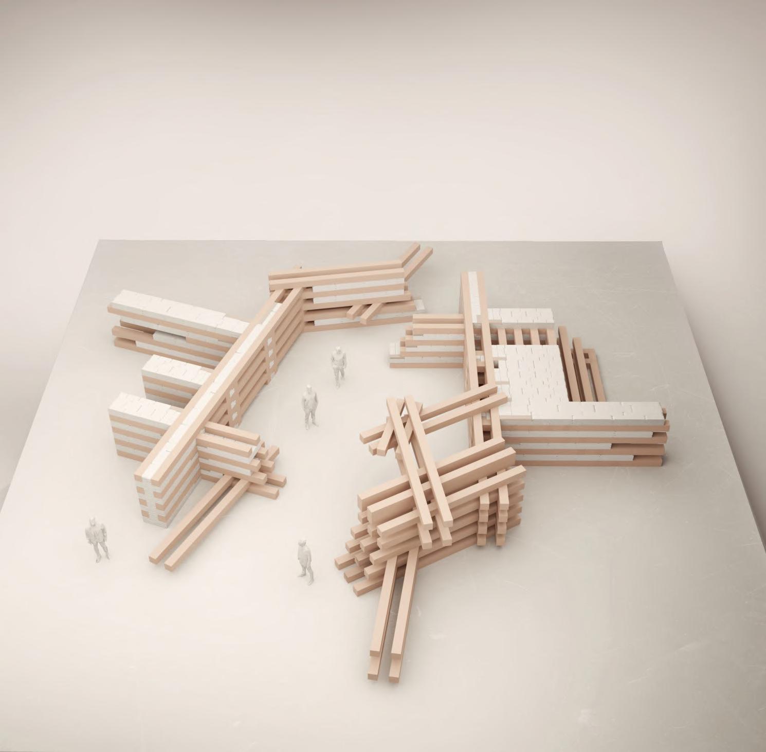
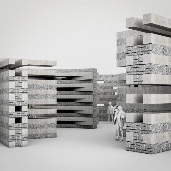
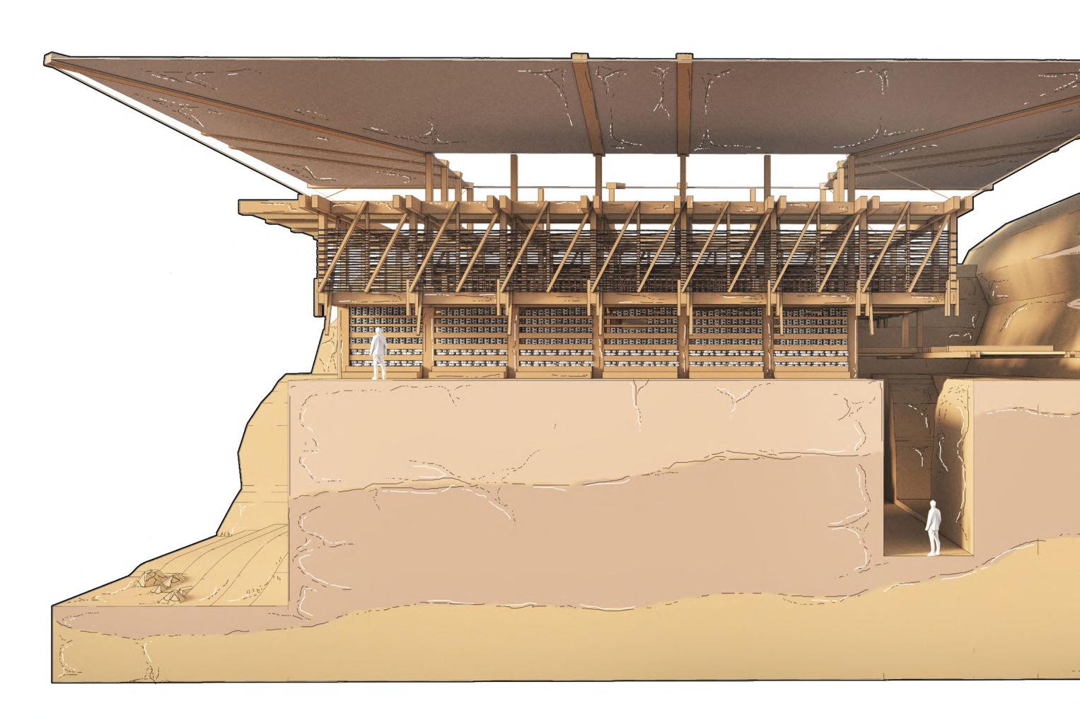
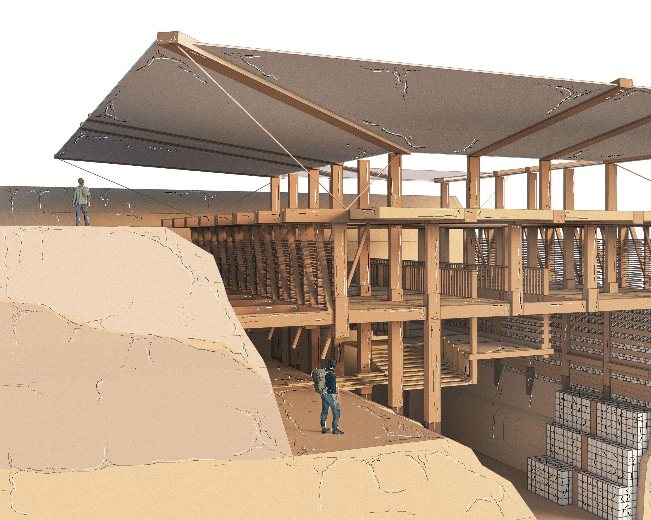
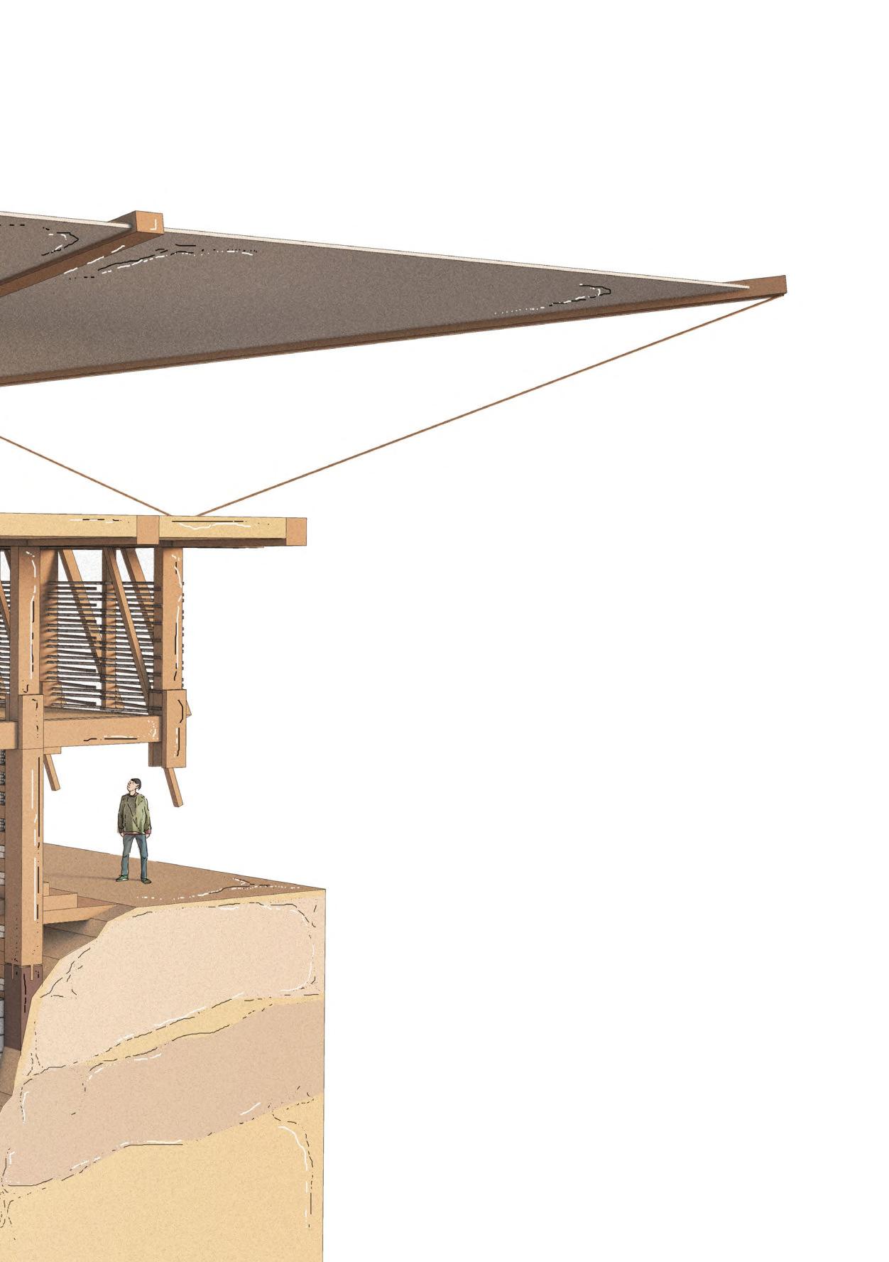
Characterised by the systematic layering of bands of timber and dry stone, ‘Lhuentse School of Crafts’ speculates on the potential of the Himalayan construction technique of Kath Khuni, and the possibilities of this novel material hybrid. While using a double skin of timber to maintain rigidity, the technique uses rubble infill to dissipate the energy from earthquakes through friction, creating a low-tech solution for the region’s extreme environment.
The proposal adopts a similar approach while speculating on its application in the remote context of Lhuentse in eastern Bhutan, a nation caught between the push of modernisation and the conservation of its unique cultural heritage.
Through the introduction of a crafts based educational programme, the scheme seeks to consolidate Lhuentse’s textiles industry with a hybrid user group of foreign exchange students and native craftspeople, diversifying the nation’s overreliance on tourism revenue and generating more capital for the nation. Consequently, the proposal aims to celebrate the region’s resourceful nature and existing infrastructure, reframing the heavily spiritualised lens through which the Himalayas is normally viewed.
KISHAN MULJI YEAR 4
@unit14_ucl Y4 KM
LHUENTSE,
kishanmulji@hotmail.co.uk
KISHAN MULJI UNIT 14
Design Tutors: Dirk Krolikowski & Jakub Klaska
Project Statement
Characterised by the systematic layering of bands of timber and dry stone, ‘Lhuentse School of Crafts’ speculates on the potential of the Himalayan construction technique of Kath Khuni, and the possibilities of this novel material hybrid. While using a double skin of timber to maintain rigidity, the technique uses rubble infill to dissipate the energy from earthquakes through friction, creating a lowtech solution for the region’s extreme environment.
The proposal adopts a similar approach while speculating on its application in the remote context of Lhuentse in eastern Bhutan, a nation caught between the push of modernisation and the conservation of its unique cultural heritage.
Through the introduction of a crafts based educational programme, the scheme seeks to consolidate Lhuentse’s textiles industry with a hybrid user group of foreign exchange students and native craftspeople, diversifying the nation’s overreliance on tourism revenue and generating more capital for the nation. Consequently, the proposal aims to celebrate the region’s resourceful nature and existing infrastructure, reframing the heavily spiritualised lens through which the Himalayas is normally viewed.
With credit to the following used as precedents throughout the project:
Graphic Reference:
Doug John Miller
Report Template Reference:
Thomas Band - Fondazione Gucci, 2020
Please refer to:
Appendix: Bibliography & Figures for all text and image references
NB. Figure 1.01A
Referenced Figure for Respective Page
Section Number
Contents HIMALAYAS, ABODE OF SNOW DESIGN DEVELOPMENTDESIGN LHUENTSE SCHOOL OF CRAFTS ENVIRONMENTAL STRATEGY 01. 02. 03. 04. 05. NB.Allworkproducedbyauthorunlessotherwisestated 01A. HimalayanSystems 1.01 HimalayanSystemsResearch- Kath Khuni Variations 1.02 AuktaHouseAnalysis- Kath Khuni: Key Elements 1.03 HybridSystemsResearch- Kath Khuni Variations 1.04 DhajjiDewari- Key Joinery 1.05 ConsolidatedJoinery 1.06 SystemsResearch- Modern Response to Extremity 01B. InitialDesignResponse- Stone/Timber Hybrid Studies 1.07 AbstractFragment- Systemising Kath Khuni 1.08 AbstractFragment- Half Lafting/Half Dry Stone Hybrid 1.09 DevelopedAbstractStudy- Half Lafting/Dry Stone Interface 1.10 AbstractFragment- Aggregation with Reinforcement 1.11 DesignResearch- Typical Retaining Wall Construction 1.12 GabionCage- Timber Reinforced Gabion Cage Skeleton 1.13 AbstractFragment- Vertical Stack 1.14 AbstractFragment- Horizontal Stack 1.15 AbstractFragment- Fluid Plinth/Light Superstructure 1.16 SpatialFragmentStudy- Stone/Timber Prototype 01 1.17 FragmentStudies- Stone/Timber Prototypes 02 1.18 SpatialFragmentStudy- Stone/Timber Prototype 03 07-08 09-10 11-12 13-14 15 16 17-18 19-20 21 22 23 24 25 26 27 28 29-30 31 32 33-34 35-36 37-38 39 40 41 42 43-44 45-46 47-48 49-50 51-52 53 54 02A. WiderSiteContext 2.01 WiderSiteContext- Himalayas Overview 2.02 WiderGeographicalContext- Himalayan Border Nations 2.03 WiderPoliticalContext- Disputed Himalayan Borders 2.04 WiderTopography- Himalayan Passes 2.05 HimalayanInhabitation- Expanding Urbanism 2.06 HimalayanInfrastructure 02B. SiteandBrief 2.07 Site- Lhuentse, Bhutan 2.08 Brief&Programme- Lhuentse School of Crafts 2.09 PlanningStrategy- Deliveries & Sourcing 2.10 Contracts&Procurement 2.11 Roles&Responsibilites 57-58 59-60 61-62 63-64 65-66 67 68 69-70 3.01 InitialZoningStudies- Global Form Development 01 3.02 InitialMassingStudies- Global Form Development 02 3.03 DevelopedMassingStudy- Design Iteration 01 3.04 PlanDevelopment- Design Iteration 02: Volumetric Study 3.05 DesignDrivers 3.06 DesignConcept01- Carved Earth 3.07 DesignConcept02- Cascading Ground 3.08 ConsolidatedDesignResponse- Carpentry Workshop 73 75 76 77-78 79 80 81 82 83-84 85-86 87-88 89 90 91-92 93-94 4.01 BuildingGenesis 4.02 MassingStrategy 4.03 Programme&Organisation- Access & Circulation 4.04 OverallStructuralStrategy 4.05 Excavation&FoundationConstruction 4.06 DryStone/TimberComposite 4.07 ToolAgetoMachineAgeTimber 4.08 MaterialSourcing- Glulam Manufacture 4.09 PrimaryGlulamStructure 4.10 HybridConstructionalHierarchy 4.11 RoofConstruction 4.12 ConstructionSequence 4.13 DormDetailStudy 4.14 CentralCourtyardDetailStudy 4.15 MechanismsoftheCarpentryWorkshop 97-98 99 100 101 102 103 104 5.01 OverallEnvironmentalStrategy- Carpentry Workshop 5.02 EnergyUse 5.03 Ventilation&Cooling 5.04 SolarGainStrategy 5.05 Acoustics 5.06 Health&Safety 5.07 FireStrategy

DESIGN RESEARCH 01A. Himalayan Systems 01B. Initial Design Response 01 Chapter BARC0174 _ AAD1LHUENTSE SCHOOL OF CRAFTS 06 SHIMLA FINAL DRAWINGS BIBLIOGRAPHY 06. 07. 107-108 109-110 111-112 113-114 115-116 117-118 119-120 121-122 123-124 6.01 AerialView 6.02 AerialEntranceView 6.03 CentralCourtyard 6.04 CarpentryWorkshopFragment 6.05 CarpentryWorkshop 6.06 1:5000SitePlan 6.07 1:500GroundFloorPlan 6.08 1:500RoofPlan 6.09 1:125LongSectionAA 127-130 131-134 7.01 Bibliography 7.02 Figures
CHAPTER 1 _ DESIGN RESEARCH 08 BARC0174 _ AAD1
DESIGN RESEARCH Himalayan Systems 01A
Kath Khuni Construction
OLD JUBBAL
The drawing explores my initial interest in Kath Khuni (cator and cribbage) construction, a technique used in all built forms in Sutlej valley of Himachal Pradesh. Using a systematic process of layering, the technique uses wood and dry stone to create stable, flexible, and strong buildings, appropriate to the region’s mountainous terrain, prone to earthquakes.
KATH KHUNI CONSTRUCTION
Characterised by layered bands of wood and stone topped off by slate roofs, Kath (wood) Khuni (corner) is used across large darbargadhs and kots (forts), intricate temples, to smaller dwellings, and is distinctive in silhouette.
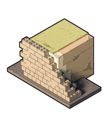
The building plinths are constructed entirely of stone. Layers of stone and wood are then constructed with a double skin and its internal cavity is filled with rubble. External and internal skins are held together by cross-braces.
The heavy stone base carries the lighter wooden structure at upper levels. No mortar is used between the courses and the shear weight of dry masonry holds it down in place.
SEISMIC PERFORMANCE
The non-rigid Kath Khuni allows the building to flex with seismic waves and to efficiently dissipate the energy generated by earthquakes.
The technique caters to the social, aesthetic and environmental sensibilities of the site. The buildings in the region have survived years of tremors, weathering and earthquakes, proving the sustainability and durability of the construction.
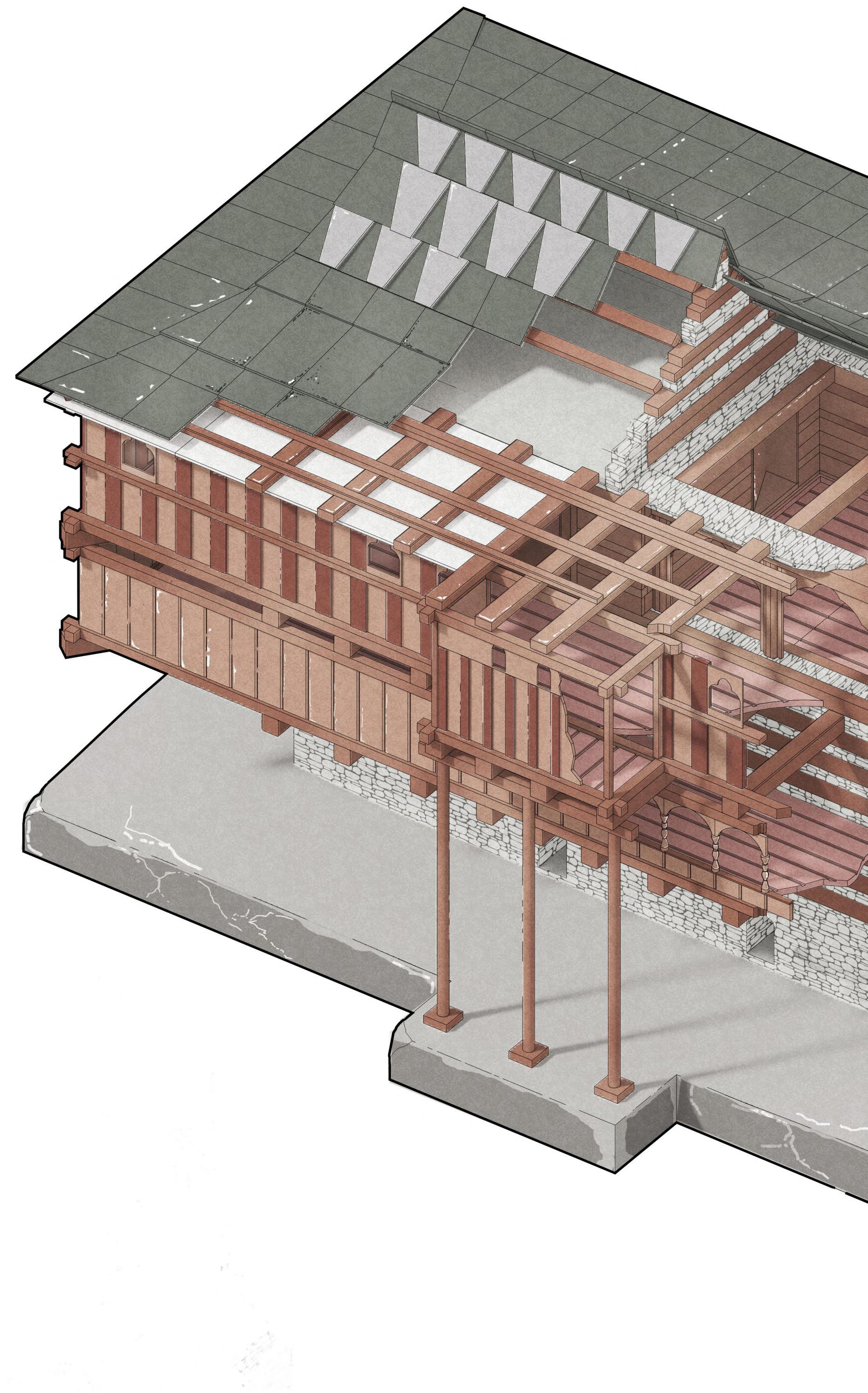
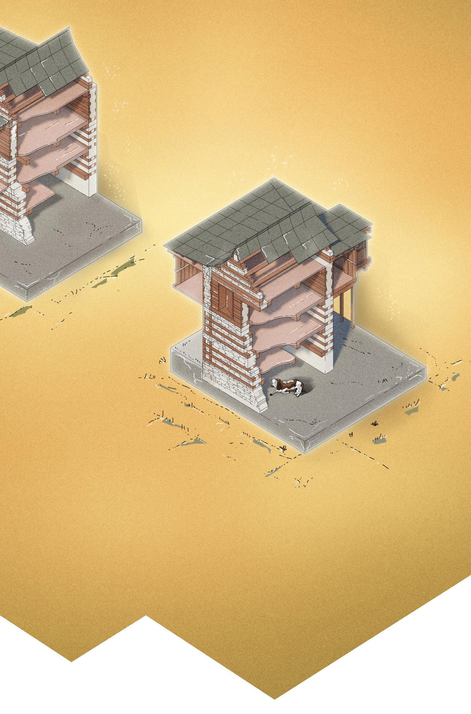
5 MAIN
COMPONENTS 01_ Foundation and Plinth 02_ Walls and fenestrations 03_ Walls and stairs 04_ Projecting wooden balconies 05_ Roof CASE STUDY: AUKTA
BUILDING
HOUSE,
01 11 02 03 04 05 06 04 05 06 01 02 03 Roof wall beam Stone slate tile Roof joist Filler wooden pieces Balcony roof purlin Roof cantilevered beam ROOF
1.01 _ Himalayan Systems Research
Figure 1.01A
OLD JUBBAL
Old Jubbal is a small hill town located east of Shimla in the Indian state of Himachal Pradesh.
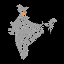
The village has been resided by Indo-Mongolian kiratas, who settled in the remote northern Himalayas, practicing Lamanistic Buddhism, alongside IndoAryans who found residence between the 12th and 16th century.
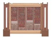
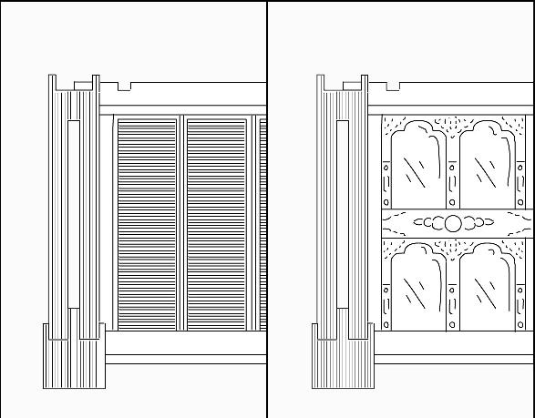
Second floor door
First floor planks
First floor beam
Stone slabs
Wall beam

07 07
08 08
12 09 09
13 10 10
14
15
11
12
13
14
15
Stone rubble infill
Stone slabs
Wall
beam
Wall
niche
WALL INTERNAL
10 BARC0174 _ AAD1CHAPTER 1A _ HIMALAYAN SYSTEMS
SHIMLA
Kath Khuni: Key Elements
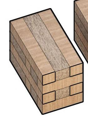
01 _ INTERLOCKING STONE/TIMBER

Using a composite application of timber bands and stone works with alternating, staggered timber beams integrated at right angles, the structure is both durable and flexible, resistant to earthquakes.
WIDER ROOF TYPOLOGY

Local roof variations include pent and gable roofs, with pitch and geometry changing in higher altitudes in response to changing patterns and intensity of precipitation in these areas.
ROOF
internal and external environments, and a wooden frame which acts as a flexible diaphragm. Two layers of slate shingles nailed to a single point to allow a degree moisture and adjust to any movement during
WIND RESISTANCE
02 _ EXTREME ENVIRONMENTS
The site’s key conditions of extremity include the mountainous terrain, the variable climate, and tectonic plate movement, which provide grounds for further exploration.
The balcony behaves as a wind blocker, protecting internal spaces from chilly winds at the valley side, with accompanying larger openings on the mountainside.
WALLLOADEDIN-PLANE OUT-OF-PLANE LOADEDWALL
03 _ SEISMIC RESISTANCE
Stiff long span timber beams, dovetail and dowel connections keeps the structure rigid, generating box-action, and transfers the lateral force from out-of-plane loaded walls directly to in-plane loaded walls.


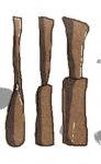
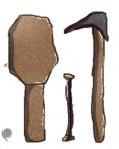
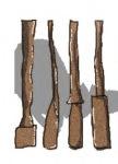
LOCAL CULTURE & WOODCRAFT


Woodcarving is integrated into local architecture through tools including nehori (chisel), hathodi (hammer), punch tools and basoki (adze), creating ornament through the expression of classical and local motifs.
JAN FEB MAR APR MAY JUN JUL AUG SEP OCT NOV DEC
MONSOON
KEY ELEMENT 01KEY DEODAR WOODWOODCARVING TOOLS
SUMMER +20C<
WINTER -10C< WINTER -10C<
AS FLEXIBLE DIAPHRAGM
BALCONY BALCONYGAUSHALA
LIVING
STORAGE
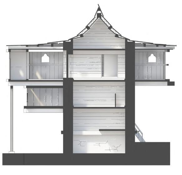
1.02 _ Aukta House Analysis
Figure 1.02A
Figure 1.02D
Figure 1.02C
Figure 1.02B
STRUCTURAL DURABILITY
Using timber under tension and stone under compression, the walls are configured to resist the sliding or overturning during land movement. Wood frames the stone that anchors the structure to gravitational forces, allowing higher damping and the quick dissipation of energy from earthquakes.
The use of a heavy stone plinth base and a lighter wooden frame construction at upper levels allows stronger distribution of mass, making it harder for the building to rock during movement.
The box shaped volume is also more effective at resisting sideways movement, distributing load transfers and shear forces during earthquake tremors.
THERMAL COMFORT
The air lock between the habitable core and balconies presents an example of passive heat containment, whereby heat is distributed evenly across the building. The stone also behaves as insulation.
DIAPHRAGM uses flexible are degree during
GF & Mezzanine Guashala (Cowshed)
First Floor Storage for grains, apples & other life support Second Floor Habitation - Bedroom, Kitchen, Living Room
PROGRAMMATIC DISTRIBUTION

Aukta House provides shelter for a family of five and three cattle. The guashala at ground level is supported by first floor storage and second floor inhabitation, alongside a second floor 1.8m cantilevered balcony supported by deodar beams.
PASSIVE HEAT GENERATION
The guashala (cowshed) located at ground level provides a base for cattle in summer, and allows the heat produced by the cattle to be directly radiated to the habitable spaces above.
Stone rubble walls also maintain internal temperature when outside temperatures reach below freezing point.
1.5M 2.8M OO O1 O2 ROOF 1.8M 1.8M 2.6M GAUSHALA STORAGE BEDROOM WC WC BEDROOM 12 BARC0174 _ AAD1CHAPTER 1A _ HIMALAYAN SYSTEMS
Kath Khuni Variations
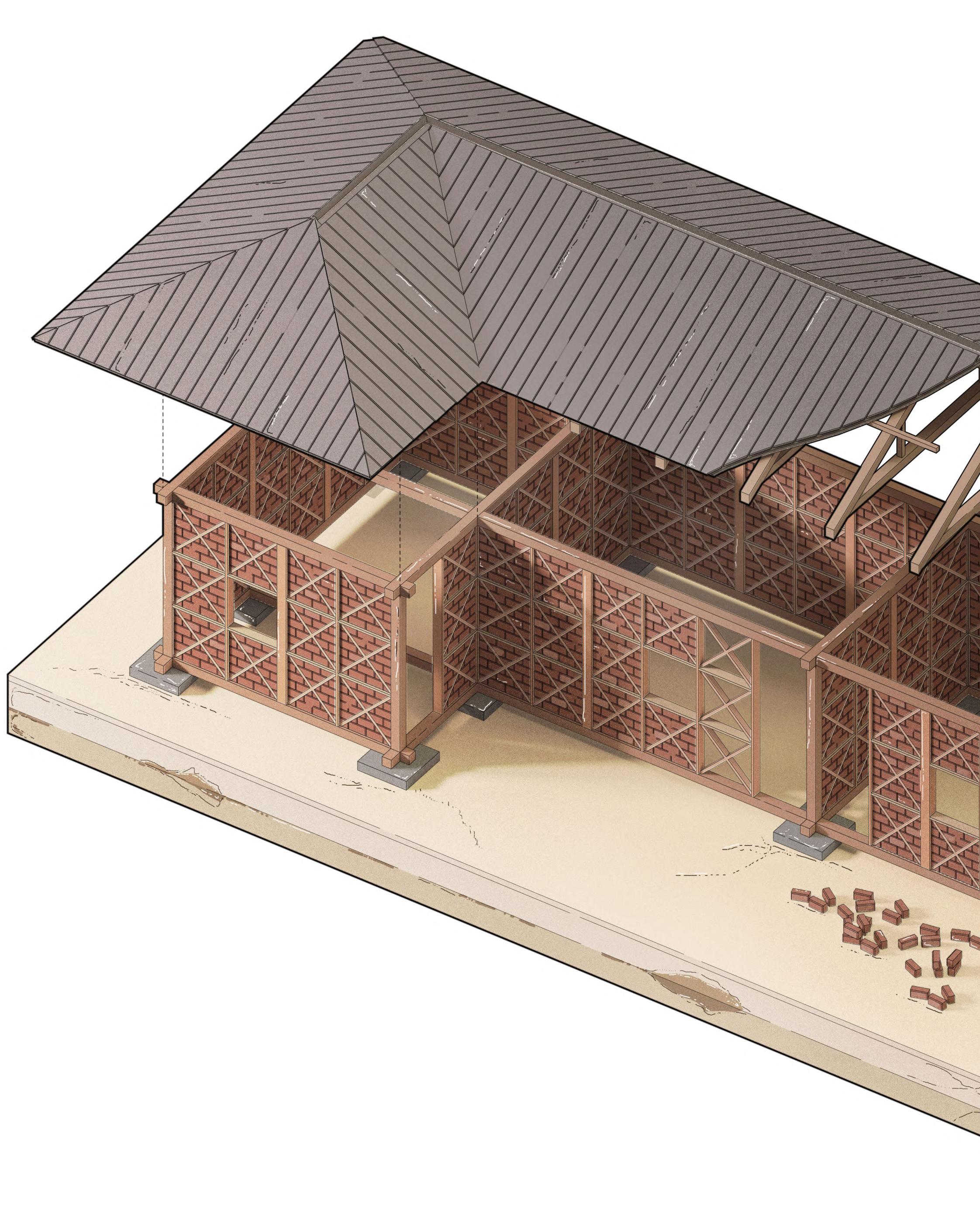
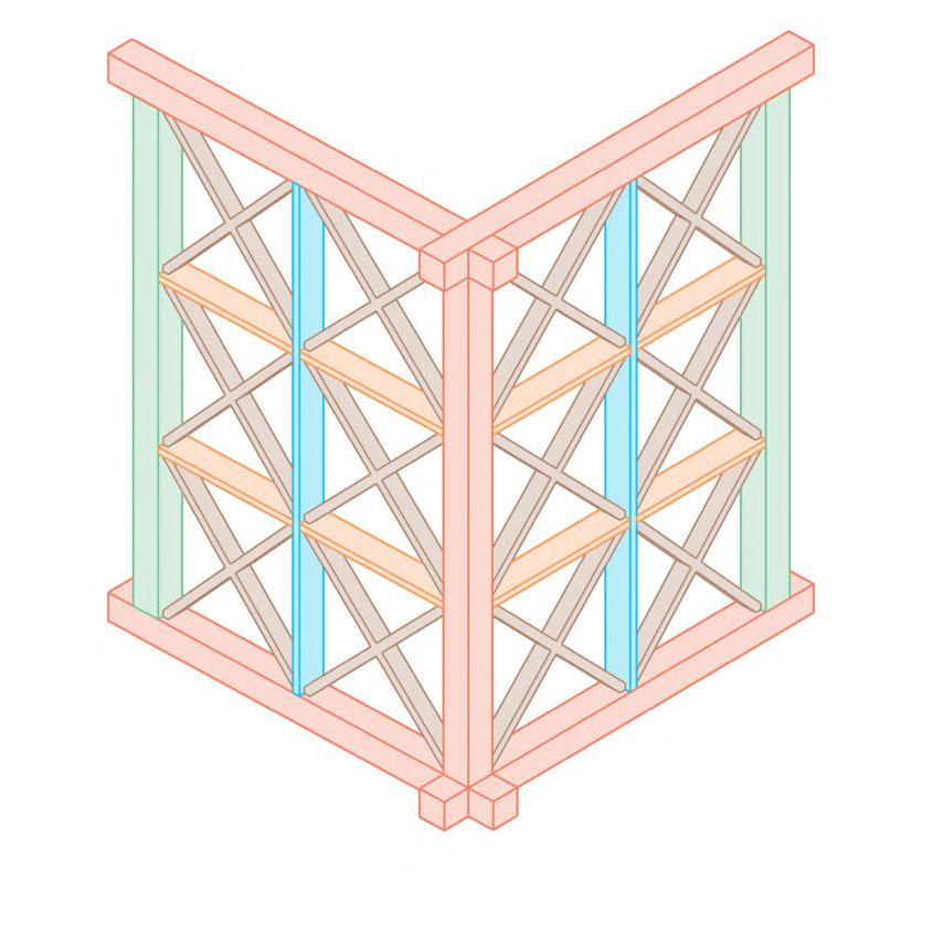
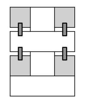
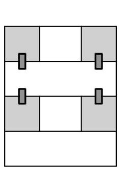
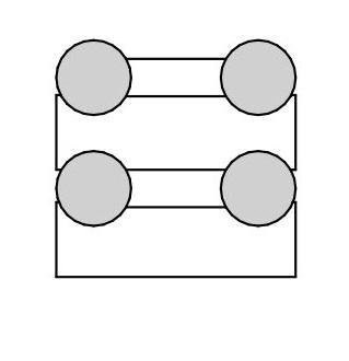
DHAJJI DEWARI
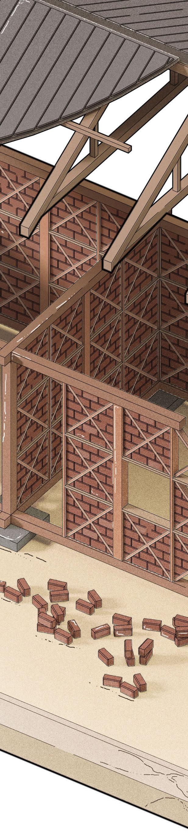
Deriving from the Persian word “patchwork quilt wall”, Dhajji Dewari is a traditional construction method found in the Western Himalayas, and behaves as an extension of Kath Khuni. It uses a simple method of half-timbering, in which timber is infilled with masonry and sometimes mud mortar.
INFILL & BRACING VARIATIONS
 Jackpads
Base Beam
Timber Cross Bracing
Main Post
Horizontal Beam
Wall Beam
Jackpads
Base Beam
Timber Cross Bracing
Main Post
Horizontal Beam
Wall Beam
TYPICAL DWELLING _ KEY PLAN
Intermediate Post
Braced with increasingly random subdivisions Regular cross
Intermediate columns with regular
1.03 _ Hybrid Systems Research
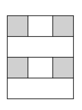
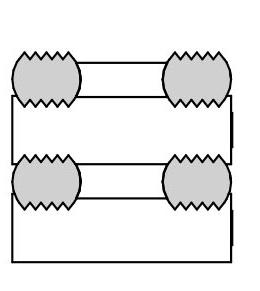
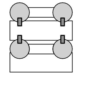
HIERARCHY OF ELEMENTS
Various components of varying thicknesses allow better load distribution. Intermediate posts and horizontal beam ends are nailed, while main posts have mortise and tenon joints.
Wall Beam and Base
Main Post
Intermediate Post
MOISTURE RESPONSE
Horizontal Beam
Cross Bracing
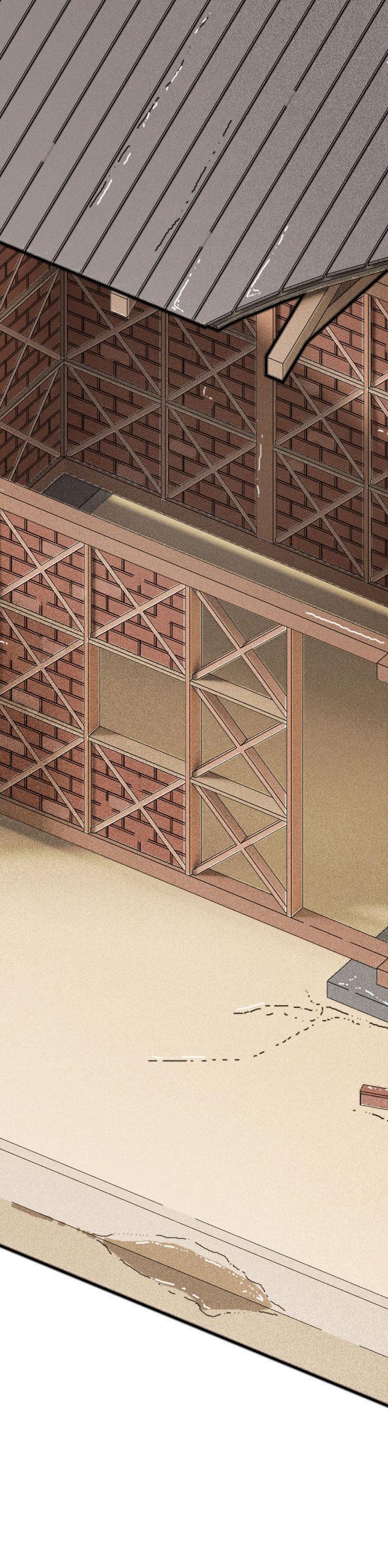
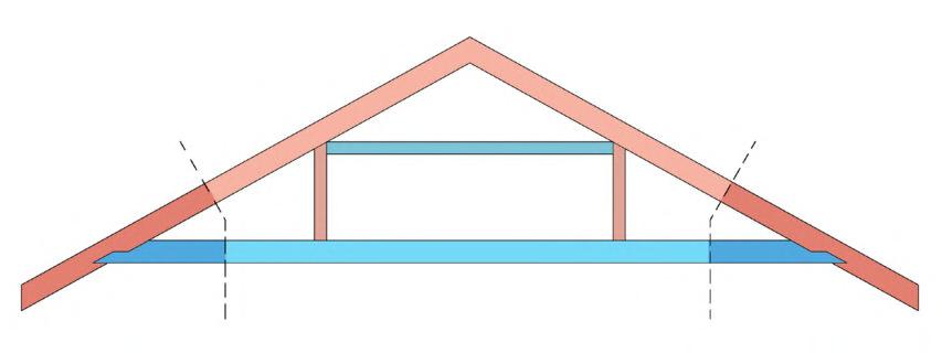
Although bricks are not traditionally used in foundations, the diagram below the roof diagram shows how a Dhajji Dewari dwelling could control moisture through the use of a damp proof course and by raising the ground floor from the ground to allow more air to circulate below. Due to the use of sand and cement mortar, timber is more susceptible to moisture build up, hence controlling the foundation is a way of easing this.
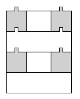
TIMBER JOINERY
Simple mortise and tenon joints and lap joints are common mechanisms used to strengthen and brace diagonal elements in Dhajji Dewari dwellings. Masonry infill offers increased friction when compression is applied to the walls. Nails allow more energy to be absorbed, and enable the timber frame to be held together, allowing the infill to be more closely confined, ensuring structural stability.
Masonry Infill
Vertical Secondary Horizontal Damp Proof Course cross bracing cross bracing Air Space Perforated Brick
Tie Beam (centre)
Rafter
Tie Beam (end) 14
Rafter (lower end)
ROOF
Figure 1.03A
Figure 1.03B
Figure 1.03C
BARC0174 _ AAD1CHAPTER 1A _ HIMALAYAN SYSTEMS
Figure 1.03D
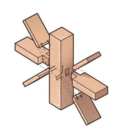
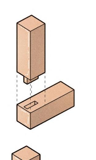
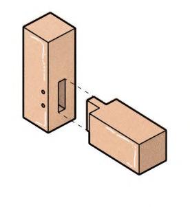
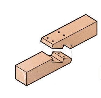
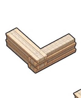
Key Joinery
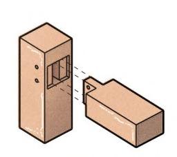
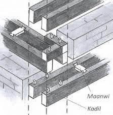
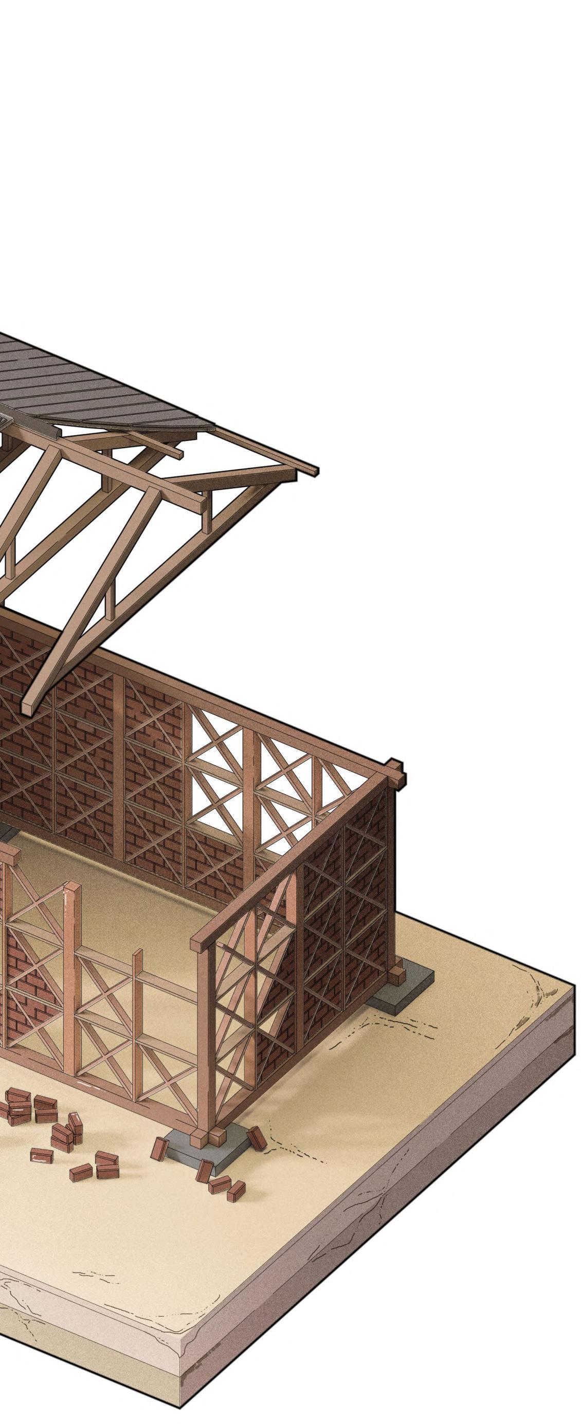
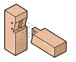
BASE PLATE - CORNER POST
The corner junction is typically made from high quality timber due to its proximity to the ground, and the perpendicular connection ensures the building acts like a box during an earthquake. The corners are locations for strategic strengthening.
WALL FRAMING
The principle members of walls are timber posts and ring beams that help to create robust frames. If connections are poorly prepared, it can result in the premature failure of the timber frame.
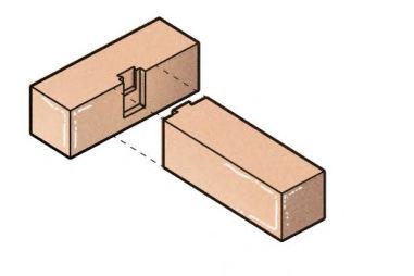
SPLICE JOINTS
The use of wooden pegs is important to prestress the connection, as well as the use of metal strapping or nailing which can improve the strength of these connections. Plane joints do not work well in tension when cross-halved, hence blocking pieces are sometimes used if the joint is not cross-halved, helping to add more interface to prevent the joint from opening.

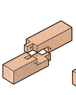
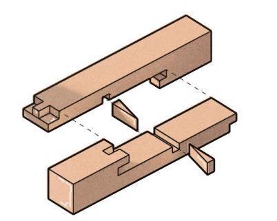

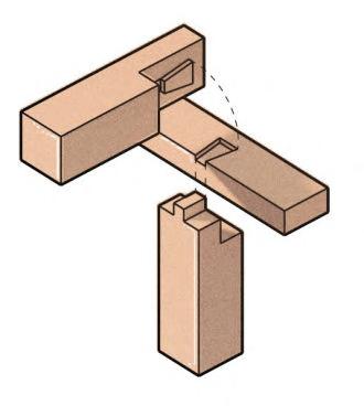
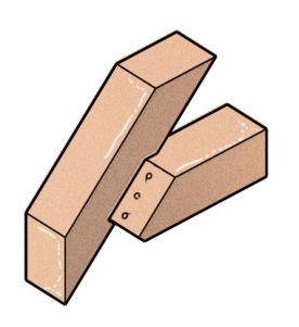

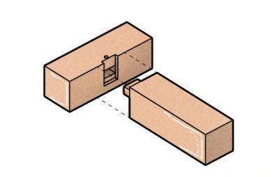
BEAM TO BEAM - COLUMNS
C displays the least amount of cut in the column; D introduces a ledge to the beam to mobilise full beam shear capacity and E shows the best housing of the beam, but the highest reduction in the column section capacity. Pegs allow the columns to have reduced tension capacity.
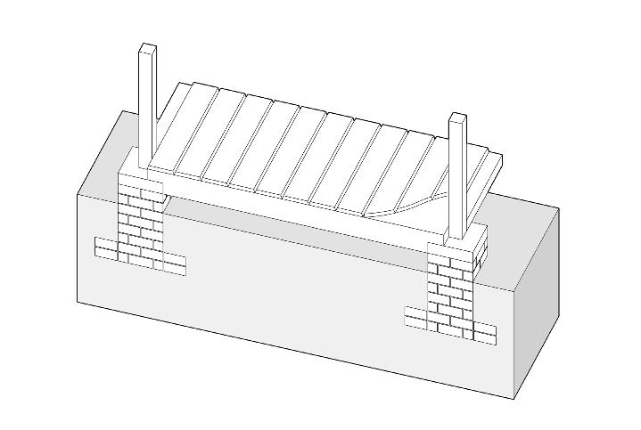
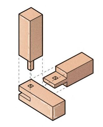
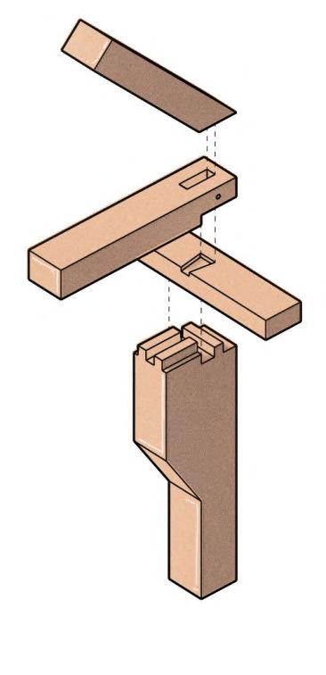
ROOF & COLUMN TO FLOOR BEAM
Roof Trusses typically use nailed connections, as well as the column to timber floor beams connection, shown below, which can be nailed to achieve larger spans, and strengthen the connection.
DHAJJI DEWARI
Construction Details
Timber frames of typical Dhajji dwellings are sometimes constructed with blunt tools, sometimes making it hard for the joints to function properly. The index of joints here are a study of typical dwellings as well as some adaptations to ensure increased strengthening of connections.
Peg gives junction limited tension capacity
Dovetail gives tensile capacity, helping to reverse load
A A B B CDE
1.04 _ Dhajji Dewari 15 Figure 1.04A
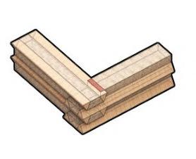
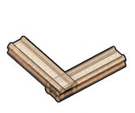
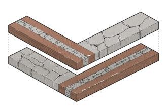
NO MORTAR JOINT
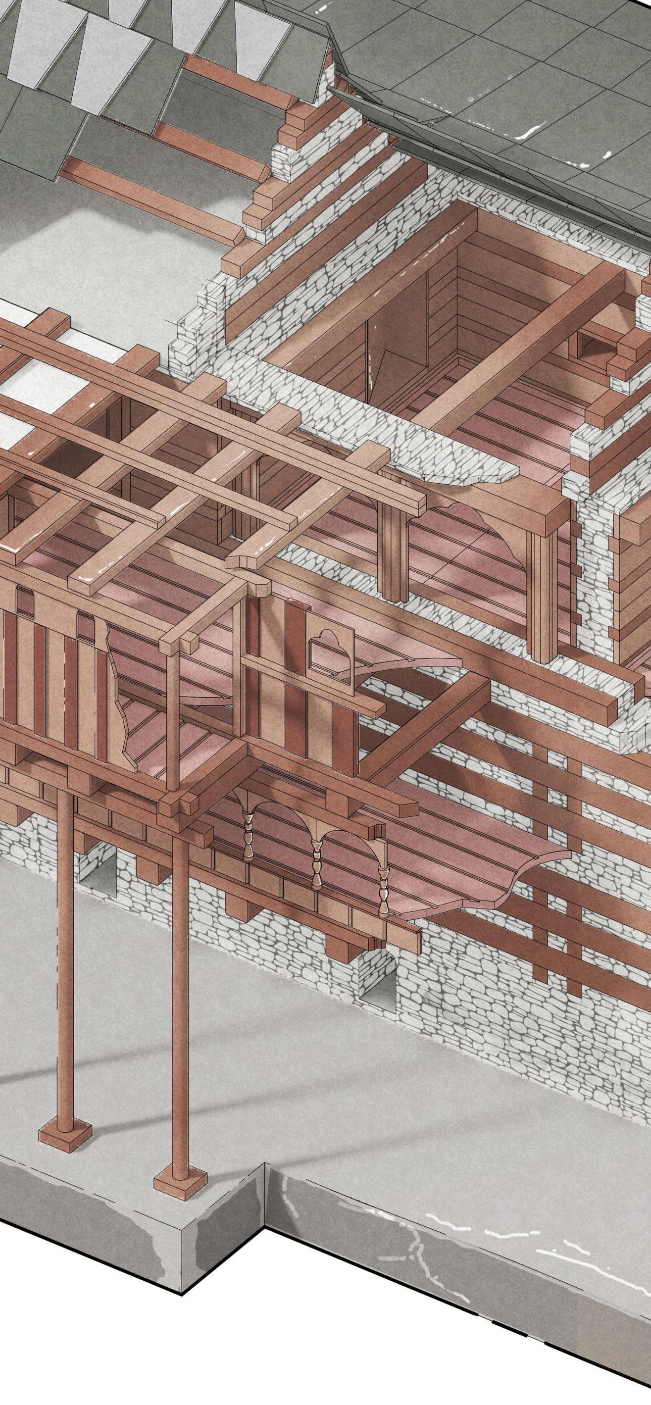
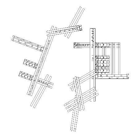
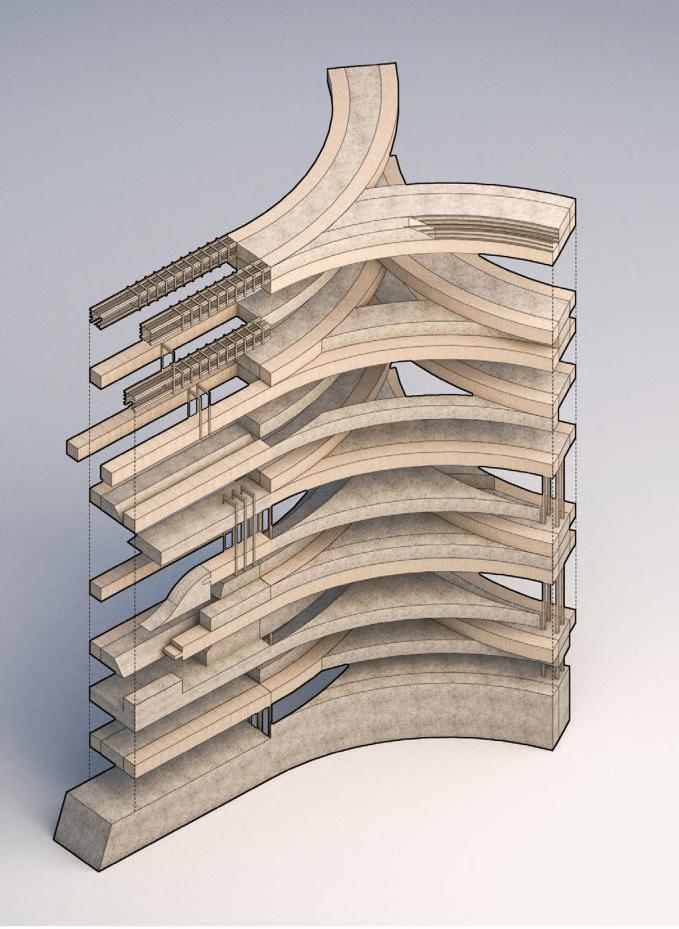
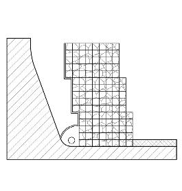
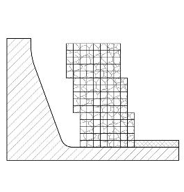
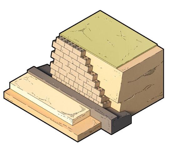
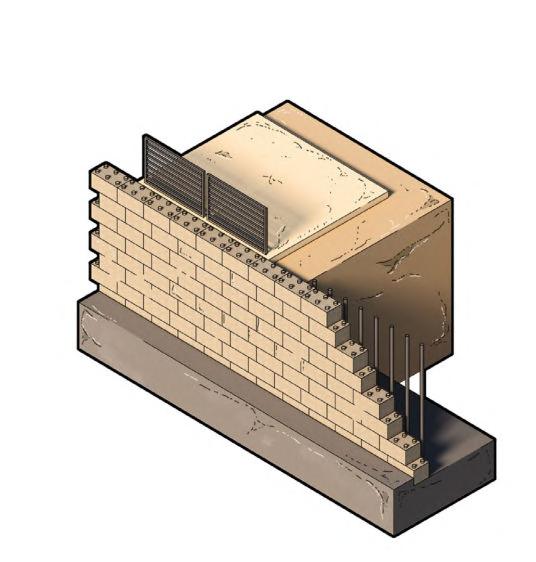
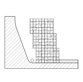
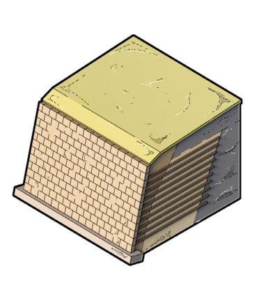
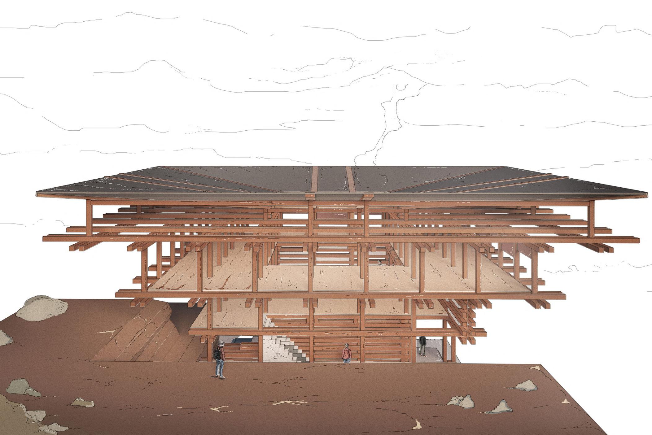
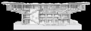
Similar to the catalogue of Dhajji Dewari joinery shown opposite, this junction looks at a precedent corner detail for a typical dwelling that uses Kath Khuni construction, demonstrating a consolidated approach to both Dhajji Dewari and Kath Khuni. The detail explores the timber stone hybrid with a changing gradient on upper levels. The plinth is comprised of dry stone and rubble infill with a cantilevered floor plate introduced on the upper storey supported by overhanging timber members. The horizontal stack displays an absence of vertical members as well as differentiated members of reduced scale on the upper storey to create less weight for the timber superstructure.

Consolidated
Section 1.05 16
Joinery
Figure 1.05A
Modern Response to Extremity
CONDITIONS OF EXTREMITY IN THE HIMALAYAS:
Extreme Cold - Heavy Snowfall
Mountainous Terrain within High Altitude
Monsoon Season - Heavy Rainfall
Dry/Arid Climate - Extreme Heat
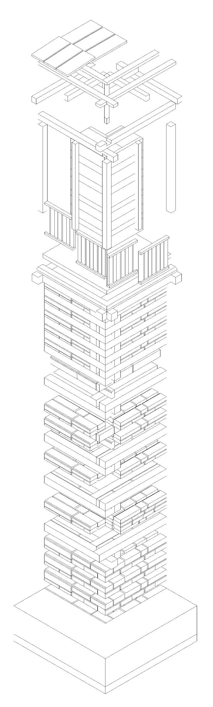
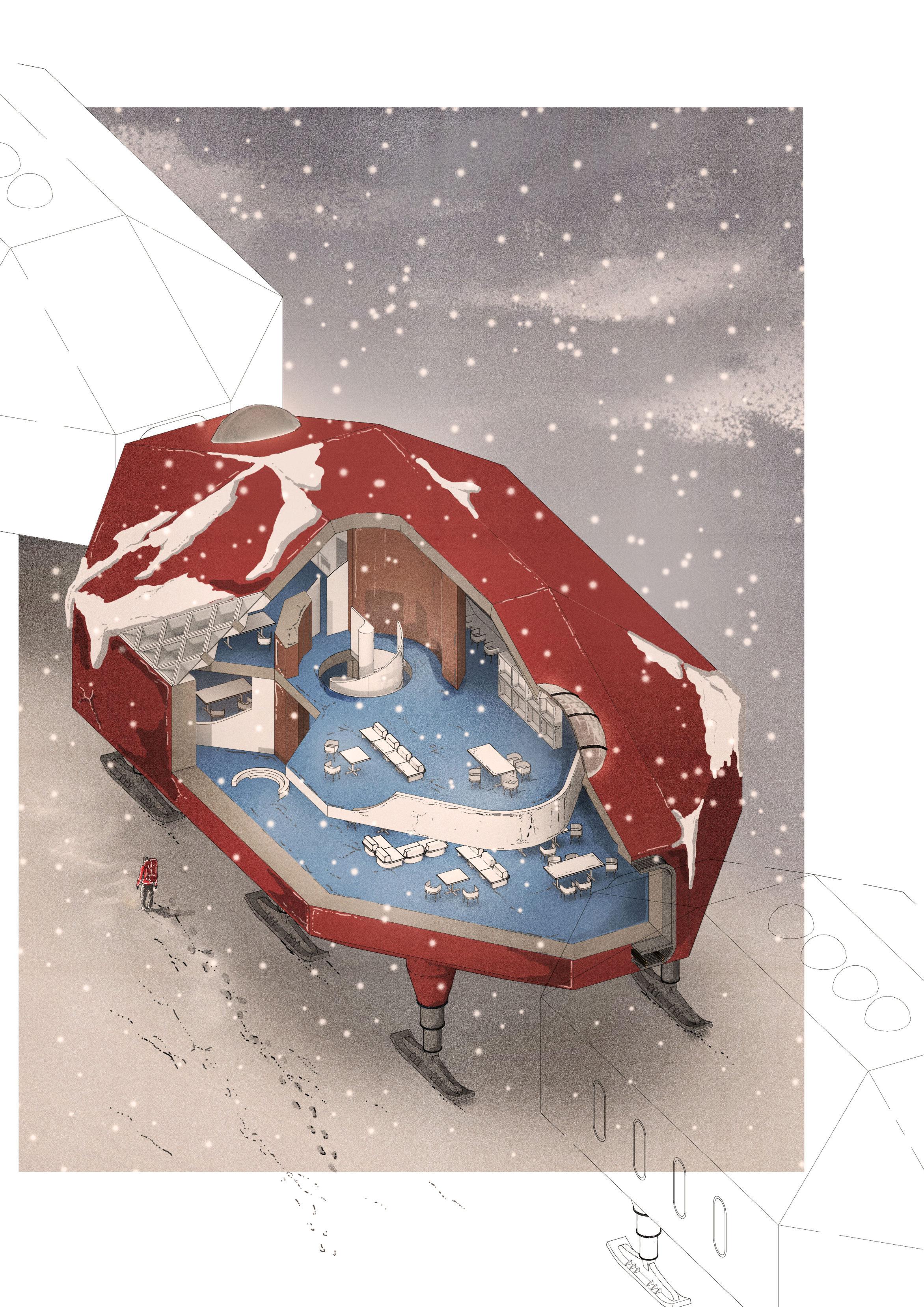
HALLEY VI RESEARCH STATION, HUGH BROUGHTON ARCHITECTS, ANTARCTICA, 75°S, 26°W
In contrast to Aukta House, the Halley VI Research Station based in Antarctica is a 21st century response to extreme cold, a condition also experienced in the Himalayas, hence I chose to explore the building as a foil to Aukta House, and compare the different methods employed within their geographically disparate, but shared climates.
Located on a 150m thick floating Burnt Ice Shelf, the building is mounted on skis, in direct response to the shelf which moves 400m per year towards the sea.
The research station’s eight self-contained modules are divided into sleep, leisure, work and living, and are self-supported by its own supply of power, water and waste disposal.
KEY COMPONENTS
Porthole window comprises steel structure clad in highly insulated composite Glass Reinforced Plastic panels
Intumescent (swells under heat exposure) coated steel space frame substructure
Hydraulic (related to liquid moving in a confined space under pressure) operated cassette within paired steel Rectangular Hollow Section structure
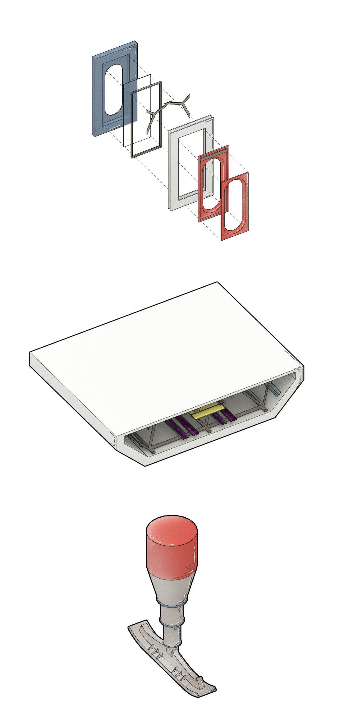
Pre-fabricated service cassette within space frame void
Double glazed curved oval cockpit rooflight allowing full views of auroral displays in winter
Hydraulic operated leg wrapped in high performance insulation and mandrel wrapped with GRP skin
EPDM (synthetic rubber) thermal break between ski and leg
Extendable steel skis - allows station to mechanically climb up

01 02 03 03 GRP WINDOWS INTEGRATED SERVICING EXTENDABLE SKI LEGS E B A A C C D D F F G G H H
1.06 _ Systems Research
Figure 1.06A
KEY PLAN BRIDGE LINK Sharing of power, drainage and water E 18 BARC0174 _ AAD1CHAPTER 1A _ HIMALAYAN SYSTEMS

Abstr 01. Systemising 02. Half 03. Aggr 04. Timber 05. Vertical 06. Horizontal 01 04 02 05 03 06
Abstract Fragments
SystemisingKathKhuni
HalfLafting/HalfDryStoneHybrid
AggregationwithReinforcement
TimberReinforcedGabionCageSkeleton
erticalStack
HorizontalStack
INITIAL DESIGN RESPONSE
20
Stone/Timber
01B CHAPTER 1 _ DESIGN RESEARCH BARC0174 _ AAD1
Hybrid Studies
Systemising Kath Khuni
Robust corners in Aukta House
Creating a negative for stone
infill to dissipate seismic load
Bending members creates stack
Double member interlock mimics Kath Khuni in section and increases strength in interlock
Robust corners to achieve box action
Extended Corner
Bending members to create stackSingle to Double member interlock
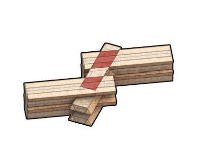
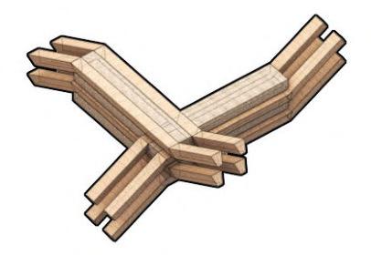
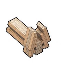
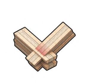
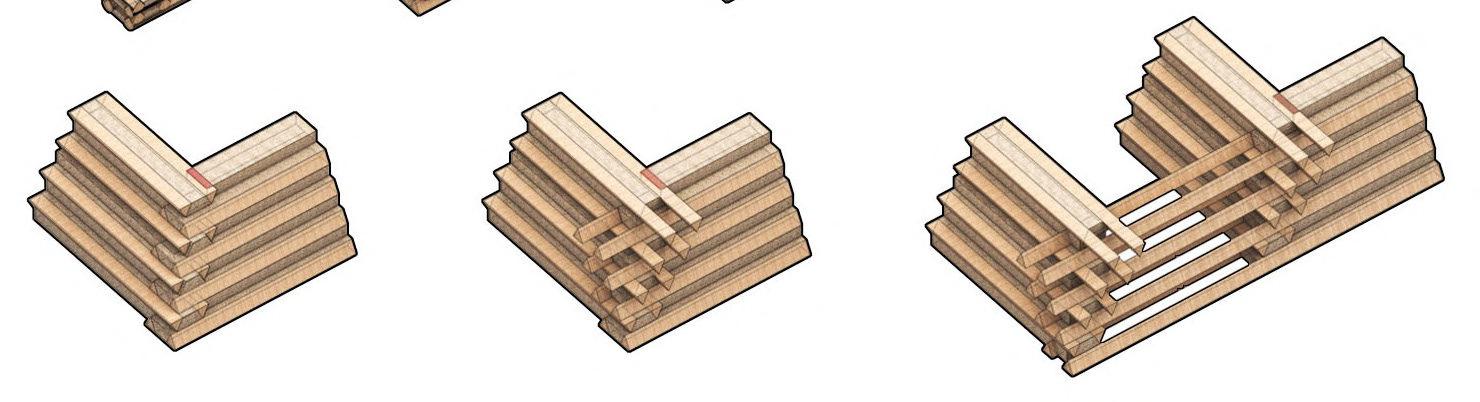
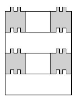
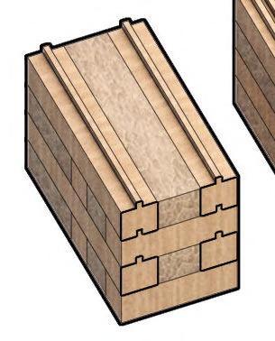
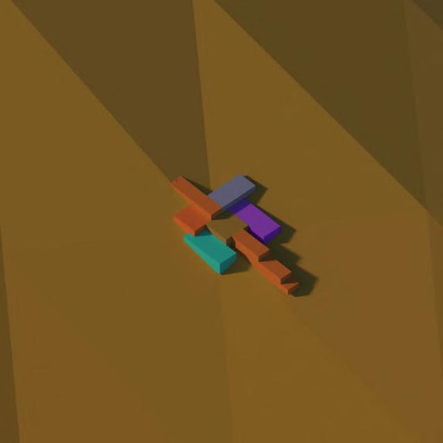
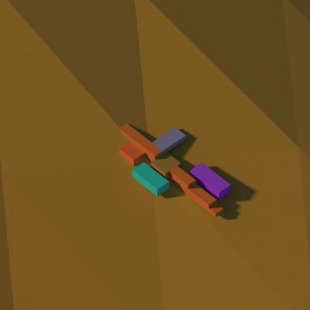
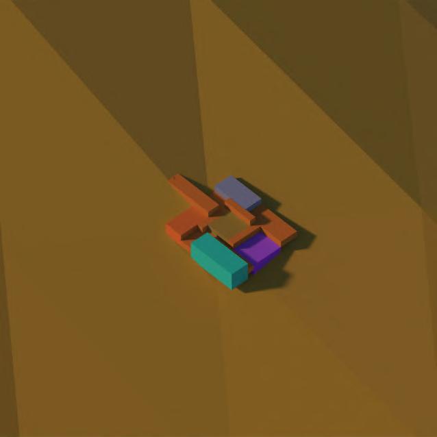
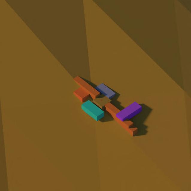
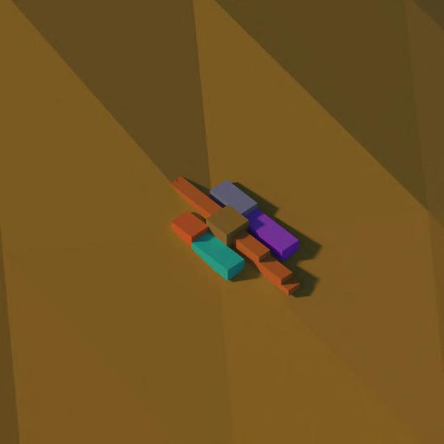
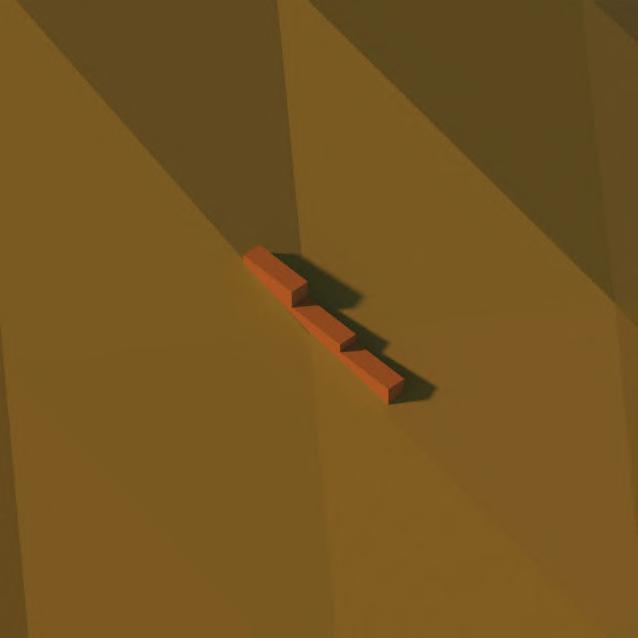
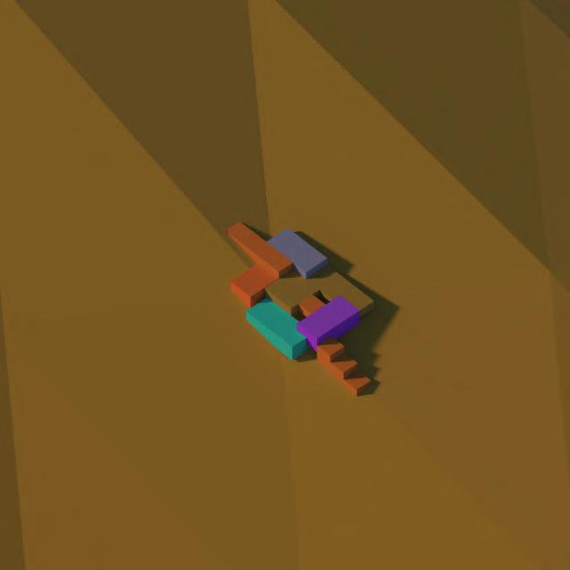
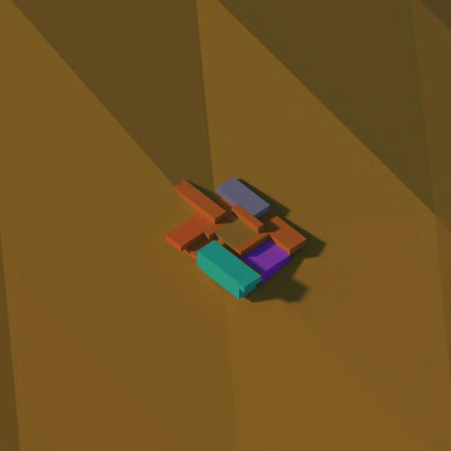
SYSTEMISING KATH KHUNI
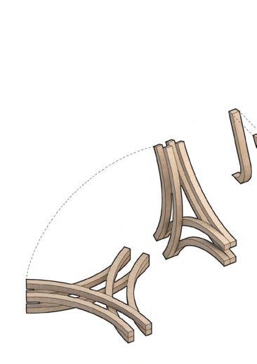
The fragment aims to translate the efficiency and seismic resistance of Kath Khuni to a larger scale by mimicking the system in section, and through the development of a system that combines adjacent members, dowel joints, single member splitting and splice joints.
Using the corners of Aukta House as reference where robust connections achieve box action, the timber members are extended, bent, stacked and infilled to create varied levels of permeability, and offer spatial opportunities.
Creating negative
Three member dowel jointTri-axial, tri-planar joint

1.07 _ Abstract Fragment 21
A A B B C CD D AXONOMETRIC PERSPECTIVE VIEW
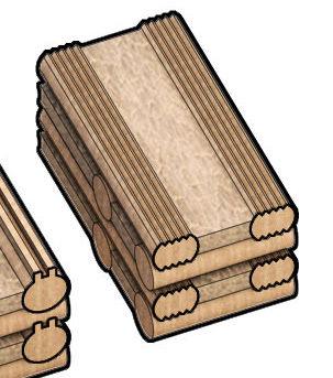
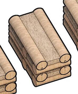
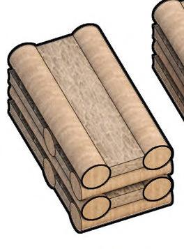
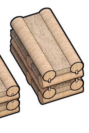
HALF LAFTING/HALF DRY STONE HYBRID
By exploring the transition from one material interface to another, the half timber lafting, half dry stone hybrid use the compressive strength of stone and the tensile strength of timber to introduce novel joinery in between material interfaces, through the exploration of variable timber profiles. Timber members are split and extended across separate axes to create differentiated aggregation, and the possibility to create scaled up spatial fragments.

The fragment translates the plinth superstructure of Aukta House into a differentiated inhabitable space, with timber members intervening with stone to create permeable counterpoints to the solid walls, and reciprocating with the base to create different points of entry when the members are splayed.

Half Lafting/Half Dry Stone Hybrid
1.08 _ Abstract Fragment
22
Traditional Circular Profile Traditional Circular Profile (Canadian) TriangularTriangular inwardTriangular chopped ABCDE KEY PLAN Triangular angled Triangular angled Triangular chopped dual vertical angled Triangular chopped dual angled Triangular chopped vertical angled Triangular angled extendedTriangular angled dual extended F I KL J GH Figure 1.08A
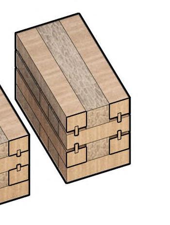
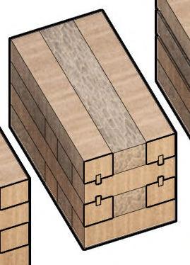
Half Lafting/Half Dry Stone Interface
FLAT SURFACE
Square profile
SPLINE SUPPORT
Square profile
CORNER SUPPORT
Square profile
ROUNDED STACK
Circular profile
SPLINE SUPPORT
Circular profile
CORNER SUPPORT
Circular profile
SINGLE INTERFACE
Tongue and Groove
DOUBLE INTERFACE
Tongue and Groove
CHAMFER INTERFACE
Tongue and Groove
SINGLE INTERFACE

Square Tongue and Groove
DOUBLE INTERFACE
Square Tongue and Groove

CONCAVE INTERFACE
Circular profile
LOG PROFILES
Full Round Swedish Cope Flat and Round Round and Flat Bevelled Edge Square Chamfered Edge Triangular ABCDEFGH AE BF CG DH
1.09 _ Developed Abstract Study 23 Figure 1.09A
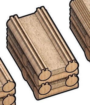
AGGREGATION WITH REINFORCEMENT
Combining Fragments 1 and 2, the use of timber reinforcement introduces a continuity between both materials, strengthening the hybrid and increasing durability, whilst reducing the construction’s weight at higher levels. Differentiated members create stronger ground and wall-to-wall interface.

A AB B
Splice joint between timber member and stone
1.10 _ Abstract Fragment 24 KEY PLAN
Curved timber member exploring continuity between timber reinforcement and thicker interface
Aggregation with Reinforcement
Typical Retaining Wall Construction

VARIATIONS
The extreme mountainside terrain of the Himalayas opens the possibility to retain soil through separate solutions including retaining walls, in particular gabion cages, which can later be adapted for varied programmatic functions. As a mechanism that contains and bleeds into the landscape, typical variations of the retaining wall allow soil retention whilst engaging different forms and uses.
REINFORCED BLOCK
INCLINED
GRAVITY RETAINING WALL
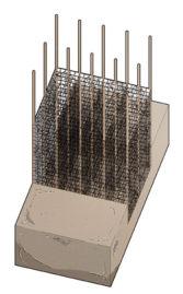
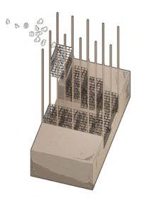
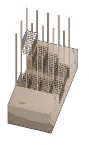
GABION WALL CONSTRUCTION PROCESS
Assembly Wire baskets/cages assembled
ADAPTATION WITH TIMBER REINFORCEMENT
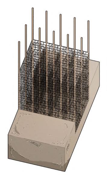
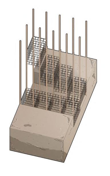
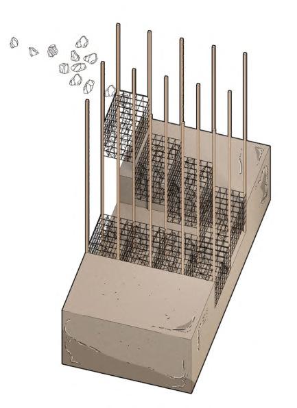
Employing a similar pre-stressed logic to that of gabion cage assembly, the concept images on the right display a mechanism in which timber reinforcement supports timber wire baskets which are later infilled with random rubble and dry stone, creating the possibility of an inhabited condition between the reinforced cage walls. Using a geotextile membrane would prevent clay and thicker earth from clogging the gabion cages.
Infill Cages infilled with random rubble/dry stones
Drainage Drainage pipe inserted at rear of wire baskets
Geotextile Geotextile membrane conceals drainage and rear of baskets
Backfill
0102030405
Rear of baskets backfilled with soil and topsoil inserted on roof of cages
Reinforce Ground dug out and timber reinforcements laid for timber mesh baskets insertion
Infill Stone and rubble infilled into baskets for added stability
Stack Baskets stacked to create an expansive wall with varied permeabilities
CRIBLOCK WALL GABION BASKET L-SHAPE REINFORCED EARTH 01 01.02.03. 02 03
1.11 _ Design Research 25
Figure 1.11B
Figure 1.11A
Timber Reinforced Gabion Cage Skeleton
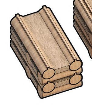
TIMBER REINFORCED GABION CAGE SKELETON
Using Aukta House as a framework to tap into the concept of an unzipped inhabitable wall to draw attention to the interstice, the fragment mediates a permeable layer of enclosure through the use of timber reinforced gabion cages. Timber members with filleted corners create slots for rounded timber cages that extend and collapse, blurring thresholds between internal and external spaces.

The cages can later be used as temporary storage devices for demolition rubble or dry stone aggregate, creating a further layer of permeability and enclosure for users.
COMBINING TIMBER REINFORCEMENT WITH BRACING & INFILL

Through the introduction of nodal points in the timber reinforced gabion cage, member sizes can be increased and diverted with varying subdivisions to reinforce areas of increased tension.
CONSTRUCTION PROCESS CONCEPT Timber members assembled Timber reinforcement creates cage Dry stone plinth Timber member Timber reinforcement Regular hybrid Cross-braced hybrid Random subdivisions hybrid Infill Stone infilled in extended wall 01 02 03
A.
A.
B.
B.
C.
C.
Dhajji Dewari inspired bracing hybrids
1.12 _ Reinterpreted Gabion Cage 26
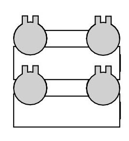
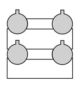
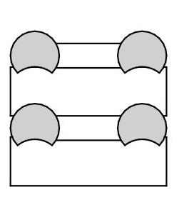
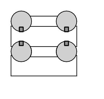
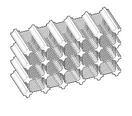
Vertical Stack
VERTICAL STACK
Using the differentiated interlocking timber members of Kengo Kuma’s Yusuhara Wooden Bridge as reference (shown in different shades of grey below), the fragment develops an orthogonal cantilevered form (as referenced in Aukta House) with a hybrid of timber members and dry stone, including a deeper base of dry stone, and stacked timber members above, creating a plinth superstructure in elevation.
ELEVATION Plinth Superstructure
YUSUHARA WOODEN BRIDGE MUSEUM Kengo Kuma Architects Short Section
AUKTA HOUSE _ SHORT SECTION
1.13 _ Abstract Fragment 27
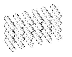
HORIZONTAL STACK
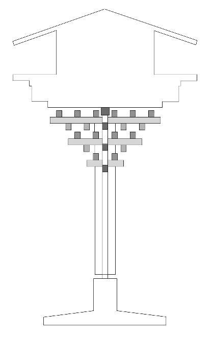
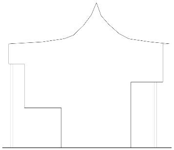
As an adaptation of Kengo Kuma’s Yusuhara Wooden Bridge Museum plan, which employs an interlock effect, the fragment explores the spatial potential of a horizontal hybrid stacking system using glulaminated timber and stone infill, within branching legs and columns. The use of tiers introduces interdependence between the members, while creating equilibrium within the overall structure.
Horizontal Stack
MEMBER DIFFERENTIATION
ELEVATION AUKTA HOUSE ROOF PROFILE Using Aukta House’s overlapping slate shingle roof tiles as reference, the fragment mimics the roof profile in section at an enlarged scale.
Rotated double member creates horizontal stack Dry stone infilled between glulam members creates wedge to increase compression outwards while tapered timber members retain tension
1.14 _ Abstract Fragment 28
Fluid Plinth/Light Superstructure
STRUCTURAL CONCEPT
Made of a heavy plinth combining aggregate with timber, a single member is repeated into a splaying volume.
CONCEPT
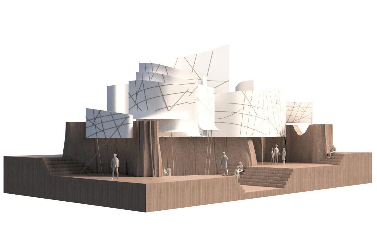
In contrast to the previous fragments exploring the stone/ timber hybrid, this fragment takes on an alternative approach, expanding on the importance of the wall in Kath Khuni. The fragment explores a more fluid form, conceptually displayed as a continuous splaying volume. Fabrics that behave as translucent shading devices dapper light into spaces below.
PROGRAMMECOMMON ROOM
Taking reference from Aukta House’s central gathering space, the fragment is divided with fluid breaks and thresholds between levels, creating a taller central space.
KEY ELEMENTS
SHORT ELEVATION Parallel Projection
Geometry
Scaled
Translucent Skins Fluting A.
1.15 _ Abstract Fragment
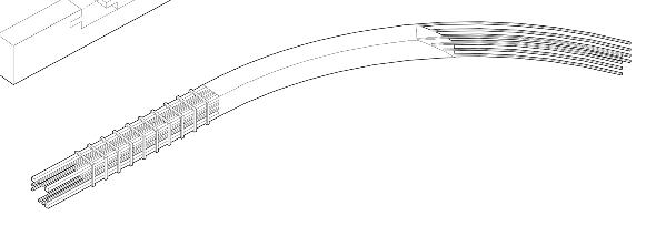
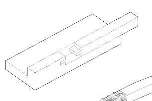
Fluted members create slotting mechanism for small scale timber members supporting skins
PERSPECTIVE VIEW
Low resolution logging transitions to high resolution milling, creating openings within wall
LONG ELEVATION A
Small scale timber members bleed into translucent skins
Layered hemp fabric offsets heavy plinth with sculptural skins
Layered fabrics dapper light
30 BARC0174 _ AAD1CHAPTER 1B _ INITIAL DESIGN RESPONSE
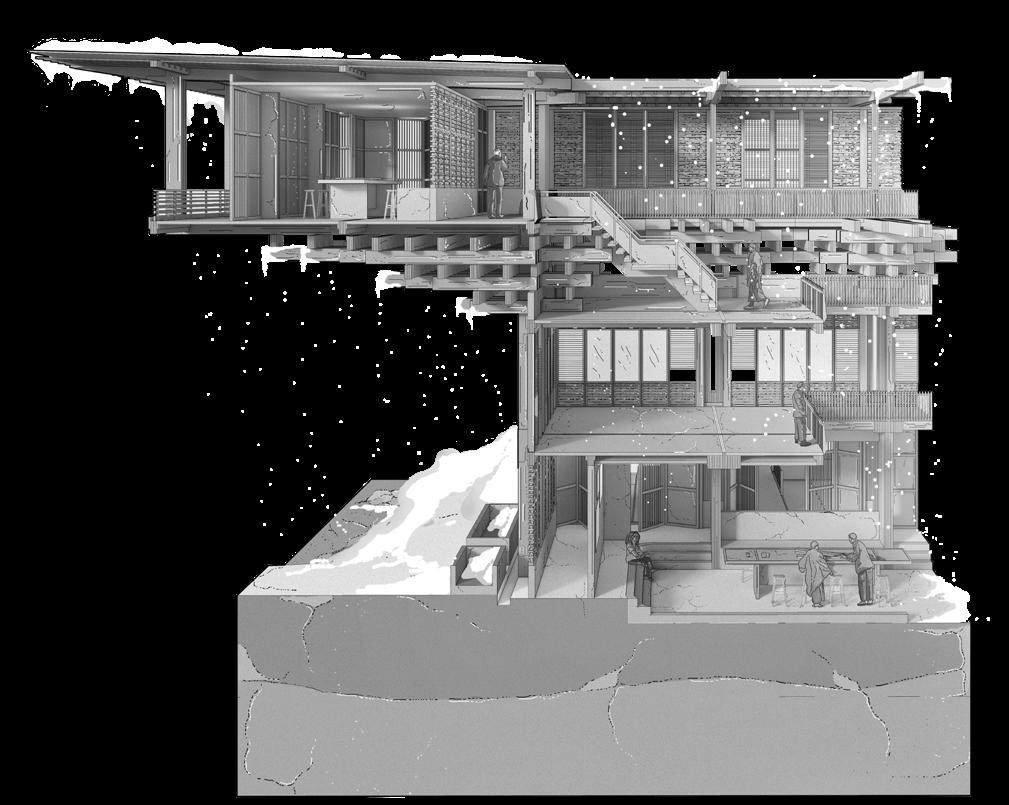
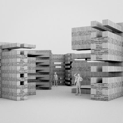
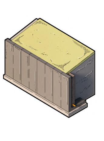
Stone/Timber Prototype 01
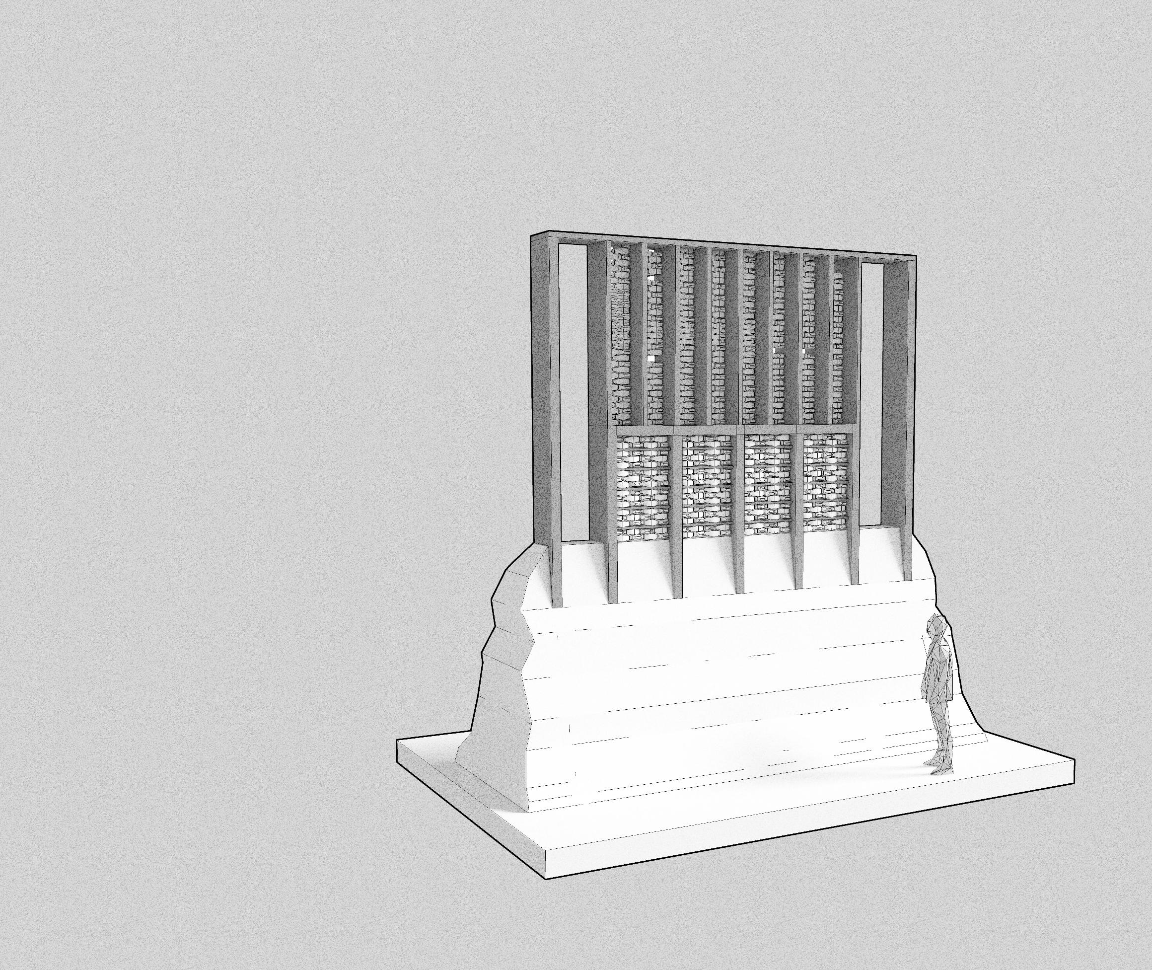
LARGE SCALE PLINTH SUPERSTRUCTURE
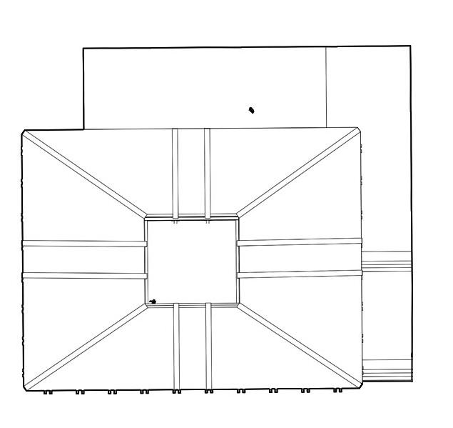
As a development of an earlier fragment titled ‘Vertical Stack’ which explored a vertical stacking system combining timber members with stone infill, this fragment speculates on the same idea at a larger scale, introducing a rock interface to present compact and expansive spatial opportunities. Using a large scale timber superstructure, sitting on top of a stone/concrete plinth, the fragment denotes a hierarchy of material, which extends to the programme through the use of a double height gathering space on the upper storeys.
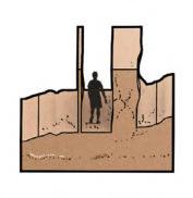
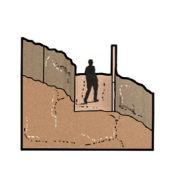
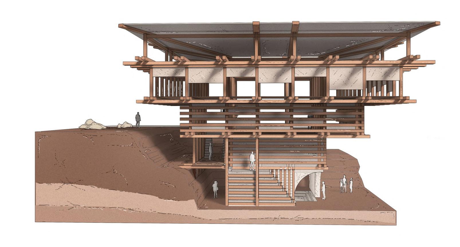
Submerged condition
Figure 1.16A
Trench condition
Figure 1.16B
Hemp fabric, native to the Himalayas, creates semi-enclosures
PLAN
Central roof opening creates untempered interior
ROOF
A.
A.
B.
C.
B.
C.
1.16 _ Spatial Fragment Study 31
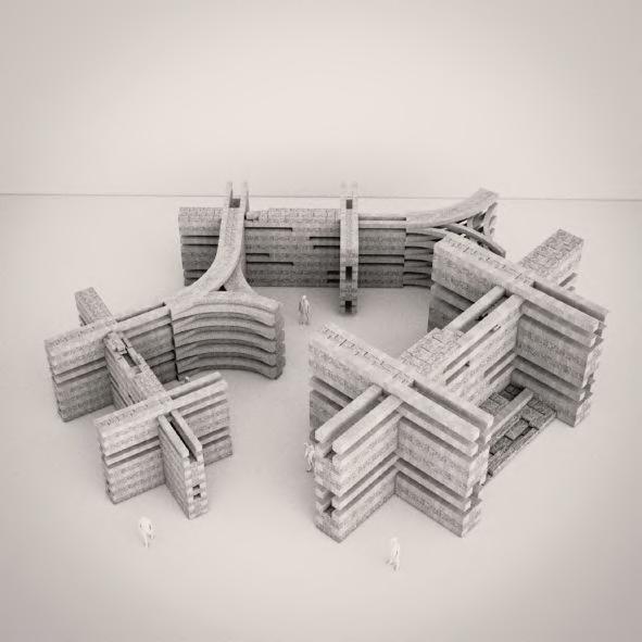
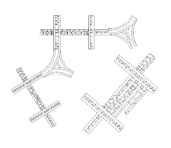
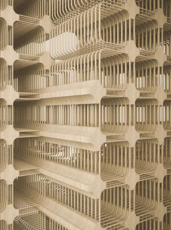
Stone/Timber Prototypes 02
ESTABLISHING A HYBRIDISED SYSTEM
Fragments 01 and 02 explore a hybridised architecture which pairs a glue laminated framework with dry stone of various sizes. Fragment 01 uses a gradient of stone sizes to create a hierarchy within the frame, while Fragment 02 uses the logic of retaining walls to bleed glue laminated members into the landscape, which then splay into differentiated sizes, creating a stronger curvilinear form and entrance.
FRAGMENT 01
Rockface to Wall Interface
A standard orthogonal grid is differentiated for permeable rubble infill.
FRAGMENT 02
Curvilinear Timber/Rubble Infill
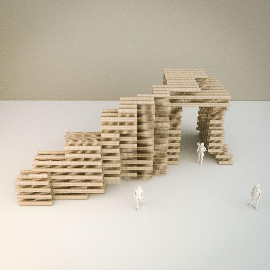
Mesh Basket Steps Study
Combining the fragments on pages 26, 28 and 31 developed into a series of splaying glue laminated members that merge into a landscape integrated retaining wall, supported by rubble infilled mesh basket steps, the elevations of which are reinforced with timber, behaving as a non-intrusive continuation of the landscape.
1.17 _ Fragment Studies 32
1.18 _ Spatial Fragment Study
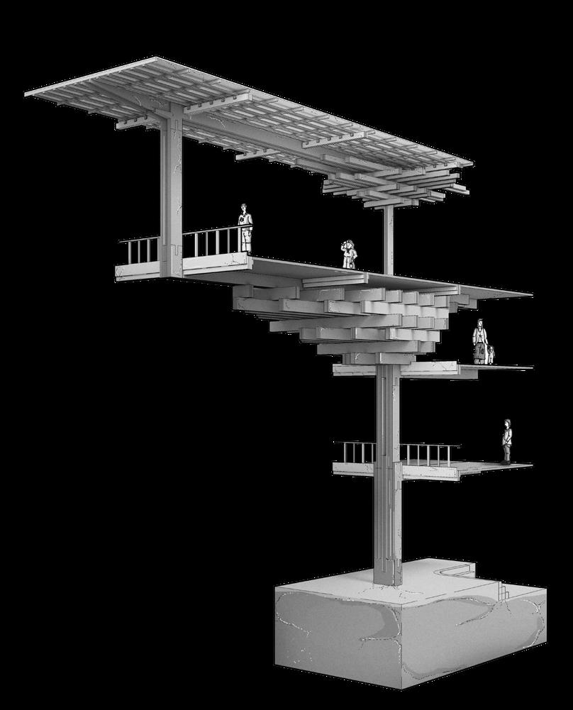
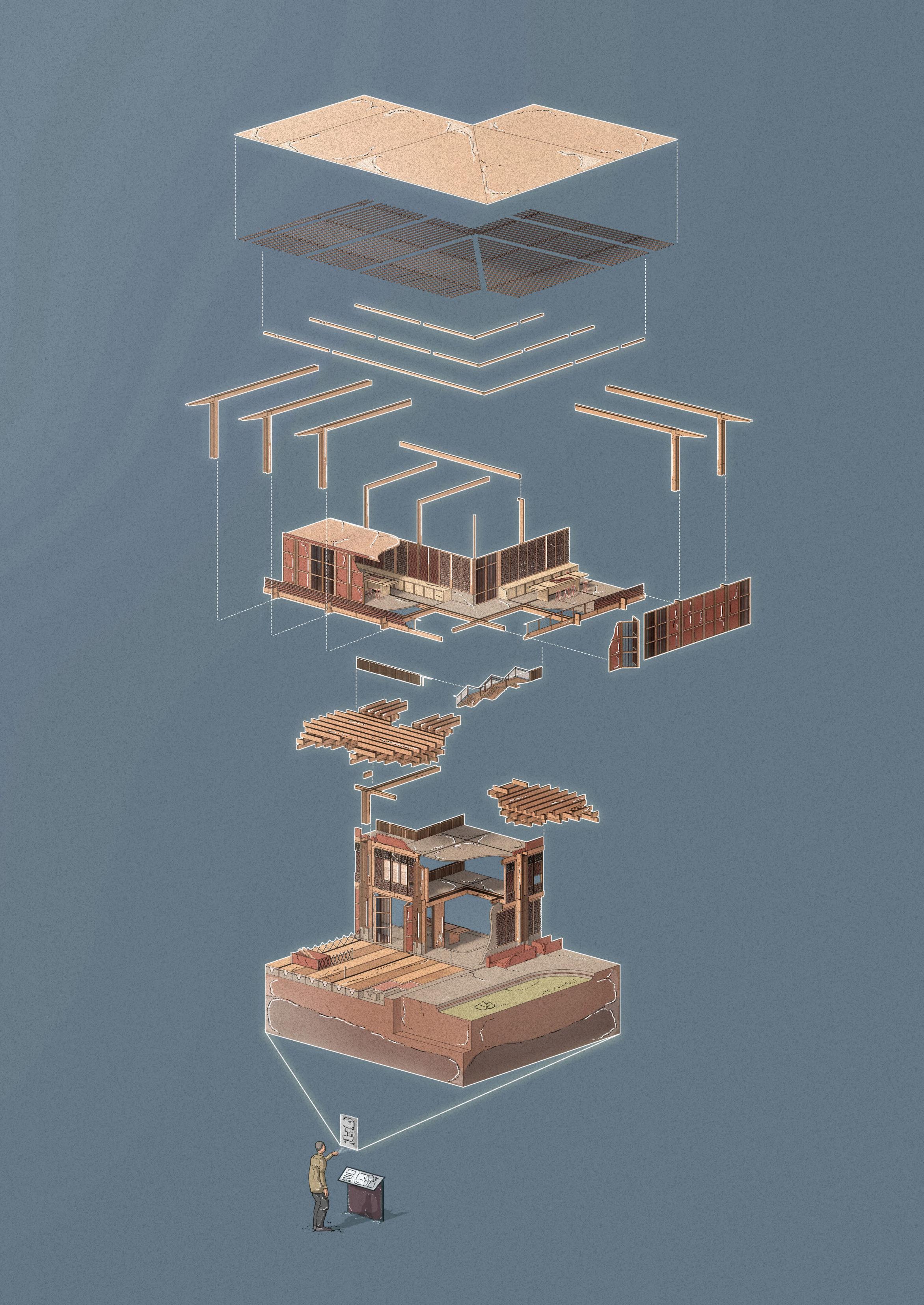
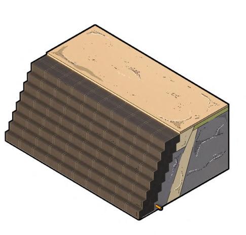
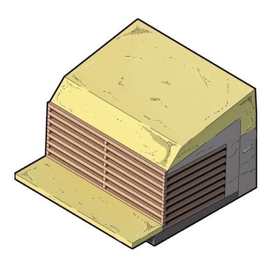
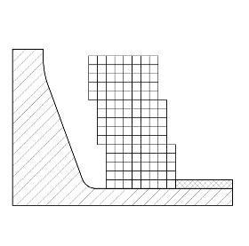
Stone/Timber Prototype 03
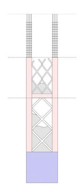
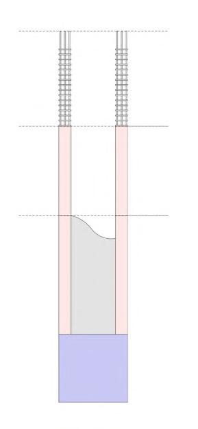
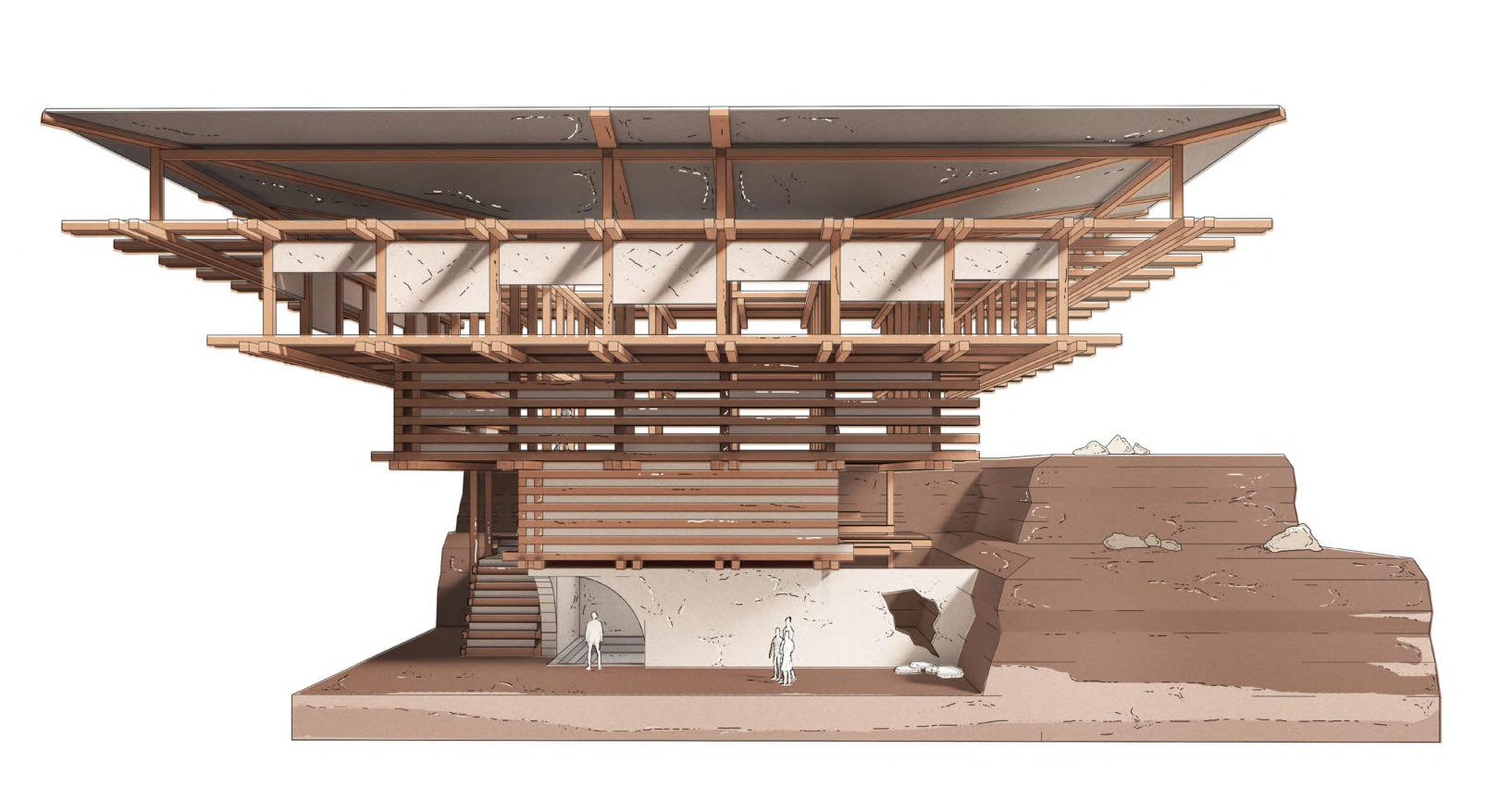
TIMBER REINFORCED PLINTH SUPERSTRUCTURE
Employing a similar prestressed logic to that of gabion cage assembly, the concept images here display a system for the plinth in which timber reinforcement supports timber wire baskets which are later infilled with random rubble and dry stone, sustaining an inhabited ground condition with a constructional hierarchy that uses varied timber members that are reduced at higher levels.
Stone Infill Gradient
Integrated Landscape
A. INHABITED GROUND CONDITION
SPATIAL OPPORTUNITY - INHABITED GROUND CONDITION
C. EXTENDED WALKWAY INTERFACE
I. Carved Plinth - Retaining Gabion W II. Inhabited Timber Superstructur III. Suspended Walkway
III.
B. COMBINED LANDSCAPE ARCHITECTURE
ENTRANCE/ SUSPENDED WALKWAY CONDITION
Suspended Walkway
 D.
ISOMETRIC
B.
D.
A.
D.
ISOMETRIC
B.
D.
A.
CONDITION Wall Superstructure
C. FRONT
alkway
GABION BASKET
Figure 1.18B
GABION BASKET I.
Figure 1.18A
34 BARC0174 _ AAD1CHAPTER 1B _ INITIAL DESIGN RESPONSE
II.
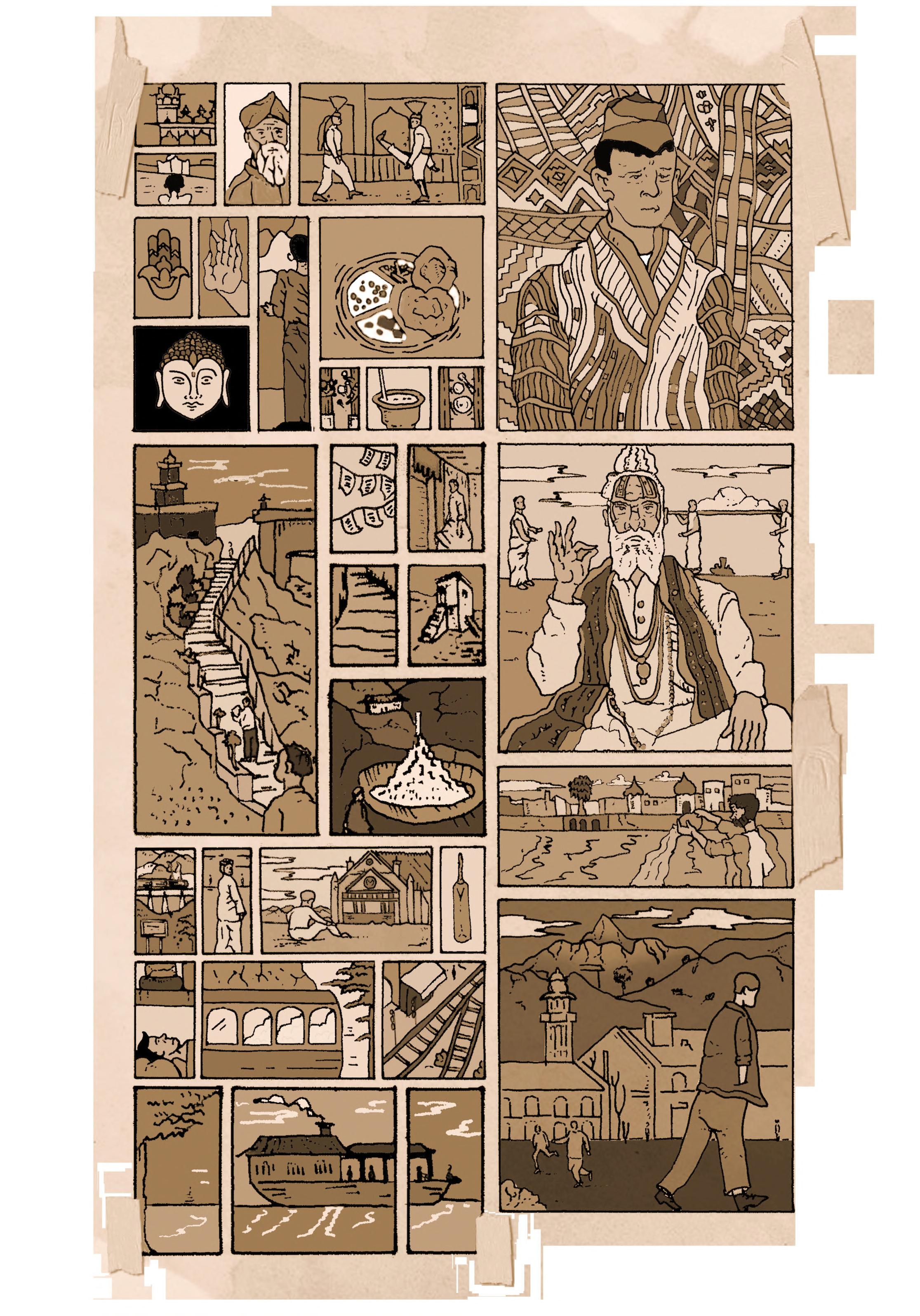
IN THE HIMALAYAS GOLDEN TEMPLEBUDDHIST SYMBOLS SADHUS A RECORD OF TRAVELS THROUGH THE HIMALAYASDEATH CEREMONY STEPS IN LADAKHFLOATING SHIMLA KHYBER PASSKALASH PEOPLEICE STUPAS BHUTANESE CLOTHING AND GEOMETRICAL PATTERNS
CULTURAL EXPRESSION
LHUENTSE SCHOOL OF CRAFTS 36 02 Chapter
OF
WIDER SITE CONTEXT 02A 02A. Wider Site Context 02B. Site and Brief BARC0174 _ AAD1
HIMALAYAS, ABODE
SNOW
Himalayas Overview
HIMALAYAN BORDER NATIONS


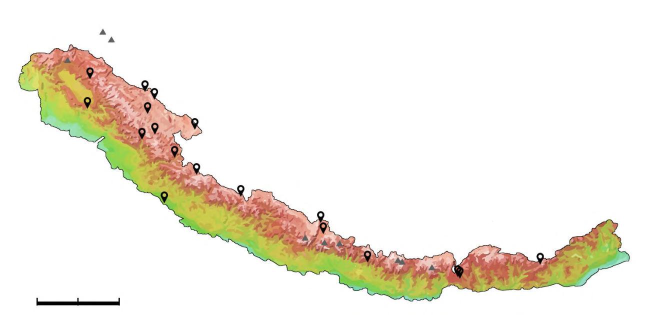
The Himalayas extend for over 2400 km from the North southward from the Tibetan Plateau to the Indus-Gangetic Plain and contain 11 peaks above 8000m, with an average height across the Himalayas of 6000m. Several border conditions are disputed between India, Nepal, Tibet, Pakistan and Bhutan, alongside several glacial sites that converge into lakes in the west. The scheme aims to re-frame the expedition, natural beauty and heavily spiritualised lens through which the Himalayas is viewed, instead drawing upon the region’s urban features to consider a new civic programme with hybrid functions and users.


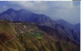
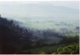
Following increased population growth in the Himalayas since the 1960s, increased strain has been placed on local resources, triggering a rise in urban dwelling on mountainous slopes, despite the majority of Himalayan inhabitants remaining rural.
The opposite mapping of major passes is a study into the man-made interventions used to navigate the foothold nature holds over the Himalayas, as well as the extreme altitude, major peaks and ultras distributed across the mountain range. Much of the passes serve as interventions for trade, vehicles and people, and respond directly to the high footfall from tourists, largely in Nepal due to trekking and mountaineering expeditions.
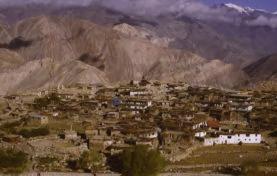
The urban fabric of many high altitude towns has changed due to the flow of migration from countryside to the city.
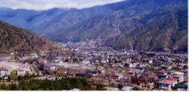
Dehra Dun, Shimla, Darjeeling and Gangtok are recent examples of Himalayan towns that have been urbanised, some of which were prominent leisure locations for colonial British military officers during the summers. Although several nations have experienced modernisation trends, Bhutan stands out as relatively insular, having never been colonised, and invites further speculation for an architecture caught between the push of modernisation and the protection of its unique cultural heritage.
EXPANDING URBANISM HIMALAYAN PASSESHIMALAYAN ALTITUDE (M) 8300m 5641m 3062m 1411m 240m 13m Passes Locations Major Peaks Pakistan Nepal India Bhutan
2.01 _ Wider
KEY (PERSONS PER HECTARE) Very High (>3) High (1.5-3) Medium (0.5-1.49) Low (0-0.49) Insufficient Data 1 810 000 1 003 000 569 578 502 197 264 991 169 578 154 019 138 951 17 820 30 870 41 377 59 490 114 551 120 414 India Nepal Bhutan Srinagar Kathmandu Dehra Dun Jammu Pokhara Shimla Dibrugarh Nepalgunj Darjeeling Thimpu Itanagar Nainital Leh Bumthang POPULATION BY RANK HIMALAYAN NATIONS DISTRIBUTION TIBETAN PLATEAU BANGLADESH MYANMAR BHUTAN INDIA N NEPAL PAKISTAN CHINA TIBET Leh Population (2011): 30 870 Pokhara Population (2011): 264 991 Bumthang Population (2017): 17 820 THIMPHU Population (2011): 114 551 Jammu Population (2011): 502 197 Dehra Dun Population: 569 578 Nainital Population (2011): 41 377 Nepalgunj Population (2017): 138 951 KATHMANDU Population (2011): 003 000 Birlanagar Itanagar Population (2011): 59 490 Shimla Population (2011): 169 578 Srinagar Population (2011): 810 000 Figure 2.01B Zoji La Elevation: 11575 ft K2 Khardung La Elevation: 18373 ft Changla Pass Elevation: 16522 ft Bara-lacha La Elevation: 14600 ft Kunzum Pass Elevation: 15060 ft Sela Pass Elevation: 13862 ft Jelep La Elevation: 13950 ft Banihal Pass Elevation: 9291 ft Rohtang Pass Elevation: 13035 ft Mohan Pass Elevation: 5900 ft Umling La Elevation: 19301 ft Shipki La Elevation: 14764 ft Mana Pass Elevation: 18478 ft Lipulekh Pass Elevation: 14436 ft Kora La Elevation: 15072 ft Thorong La Elevation: 17769 ft Arniko Rajmarg Elevation: 17260 ft Nathu La Elevation: 14140 ft NANGA PARBAT DHAULAGIRI ANNAPURNA MAKALU KANGCHENJUNGA MANASLU MT EVEREST GASHERBRUM Figure 2.01A Figure 2.01C 2.04 2.05 Jharkot VillageNakho VillageBhutanNepalNepalDoon 2.02
Site Context
The infographic looks at the highest 38 peaks across the Himalayan mountain range, gauging the altitude range,
potential footfall for tourism, and the peak distribution and borders by nation. First ascents range between
the years of 1931 and 1992, with the highest peaks having been summited in the 1950s.

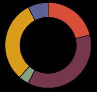
Peak Distribution by Country 8% Bhutan 4% Pakistan 21% India 31% China 36% Nepal Himalayan Peaks: Commodifying Nature Nepal India 5000 Mount Everest K2 KanchenjungaLhotseMakaluChoOyuDhaulagiriIManasluNangaParbatAnnapurnaIShishapangmaGyachungKangNuptseNandaDevi Namcha BarwaKametGurlaMandhata Gangkhar PuensumKulaKangriYangraLabucheKangJomolhariGyalaPeriLangtangLirungTongshanjiabuNoijinKangsang NunKangto MachapuchareDorjeLakpaKedarnathKedarnathIIAmaDablamKangtega Mount KailashManaPeakBandarpunch 5000 00 1000010000 1500015000 2000020000 2500025000 3000030000 3500035000 32500 19301930 19401940 19501950 19601960 19701970 19801980 19901990 20002000 32500 2750027500 2250022500 1750017500 1250012500 75007500 25002500 Pakistan China Bhutan Altitude (ft) Country Name First Ascent Unclimbed 38
BARC0174 _ AAD1CHAPTER 2A _ WIDER SITE CONTEXT
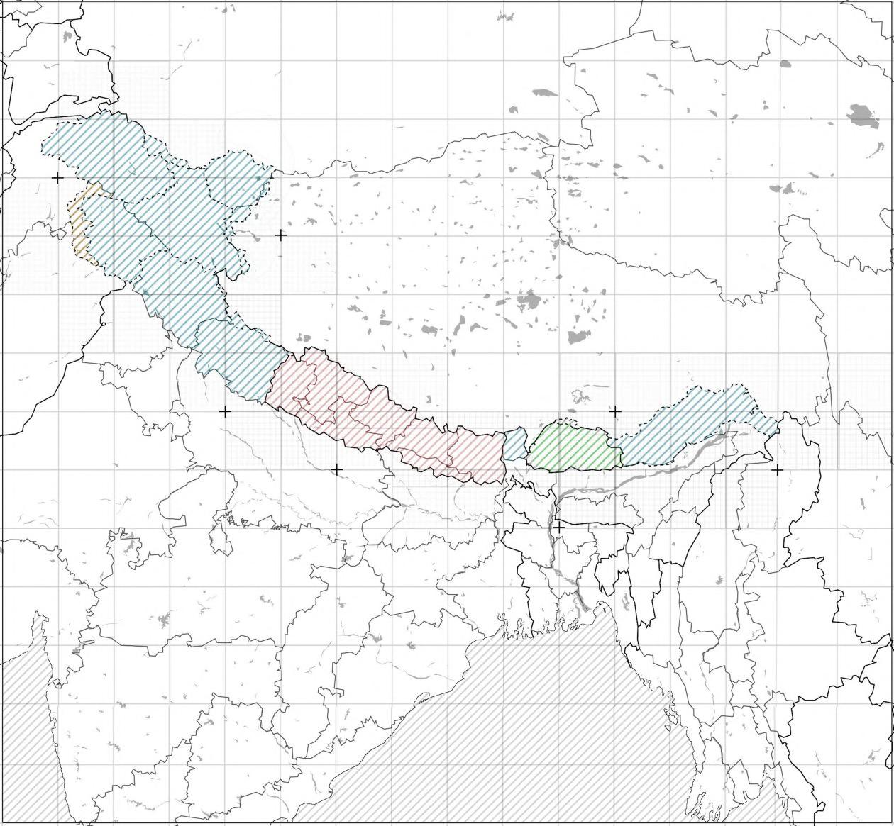
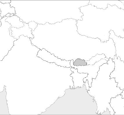
Himalayan Border Nations

WIDER GEOGRAPHICAL PARAMETERS
Containing 11 peaks above 8000m, with an average height across the Himalayas of 6000m, the Himalayas extend for over 2400 km from the North southward from the Tibetan Plateau to the Indus-Gangetic Plain. Covering the territories of India, Nepal, Tibetan Autonomous Region, Pakistan and Bhutan, several border conditions are disputed. The width of the mountain system varies from 180 to 350km, with a total area of 650 000 sq km.

The Himalayas are also home to the source of the Indus, Ganges, and Brahmaputra rivers, some of which converge into lakes, predominantly in the Western Himalayas, containing tectonic and glacial origins.
BANGLADESH MYANMAR BHUTAN INDIA N NEPAL PAKISTAN
TIBET
TIBETAN PLATEAU
CHINA
HIMALAYAN NATIONS DISTRIBUTION HIMALAYAN STATES 01 0105 04 0207 08 03 02 03 05 04 08 07 Pakistan Nepal IndiaBhutan Jammu and Kashmir Himachal Pradesh Uttarakhand Sikkim Nepal Arunachal Pradesh Bhutan
2.02 _ Wider Geographical Context 39
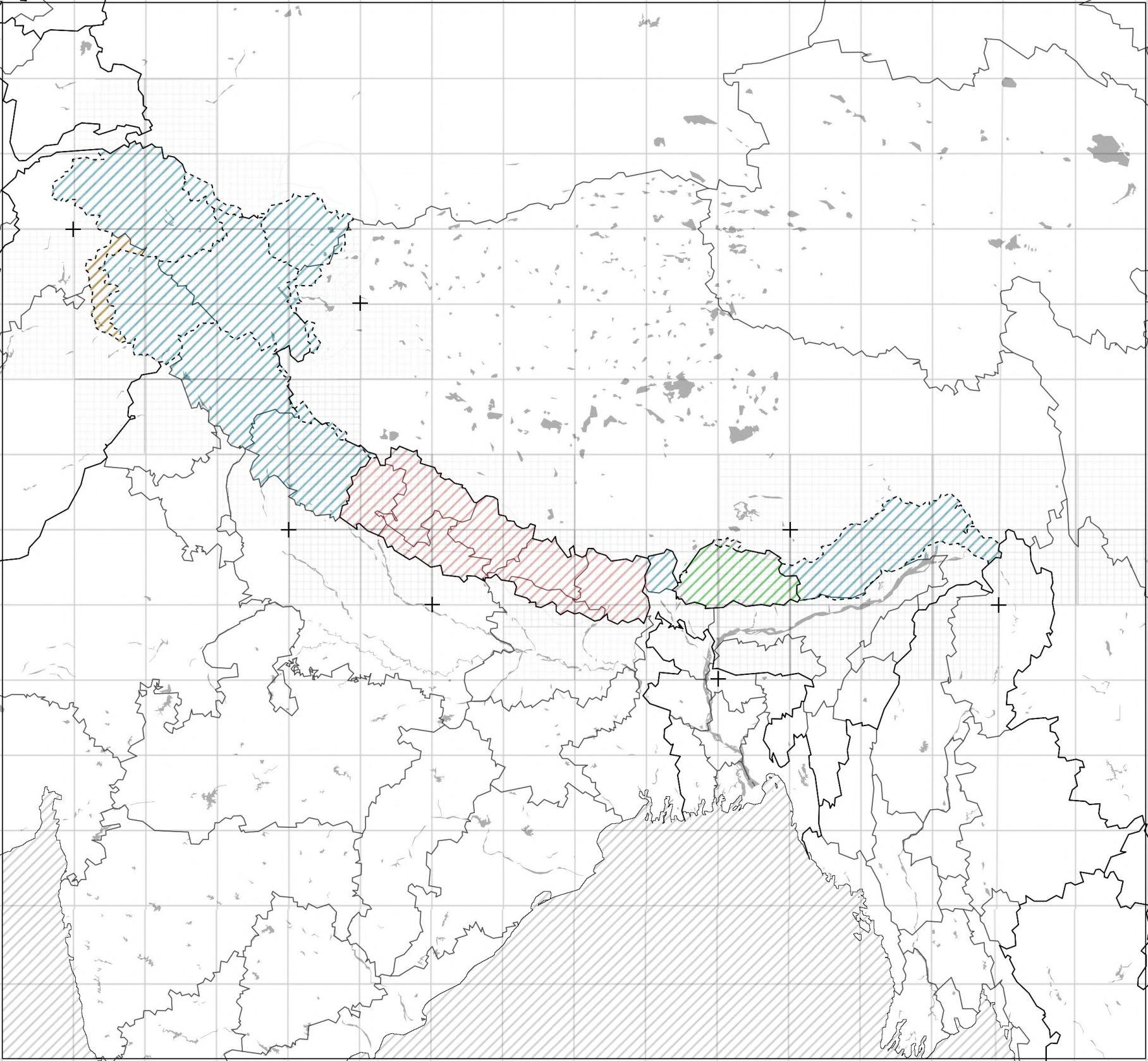
Kashmir is the site of multiple disputed areas, having seen multiple skirmishes between Indian and Chinese troops. Both India and China are competing to build infrastructure along the border, known as the Line of Actual Control. India’s proposal for a new road to high-altitude air base is considered the cause of a 2020 clash. The diagram explores sites of contention within the wider Himalayas, alongside accompanying transport infrastructure interventions.
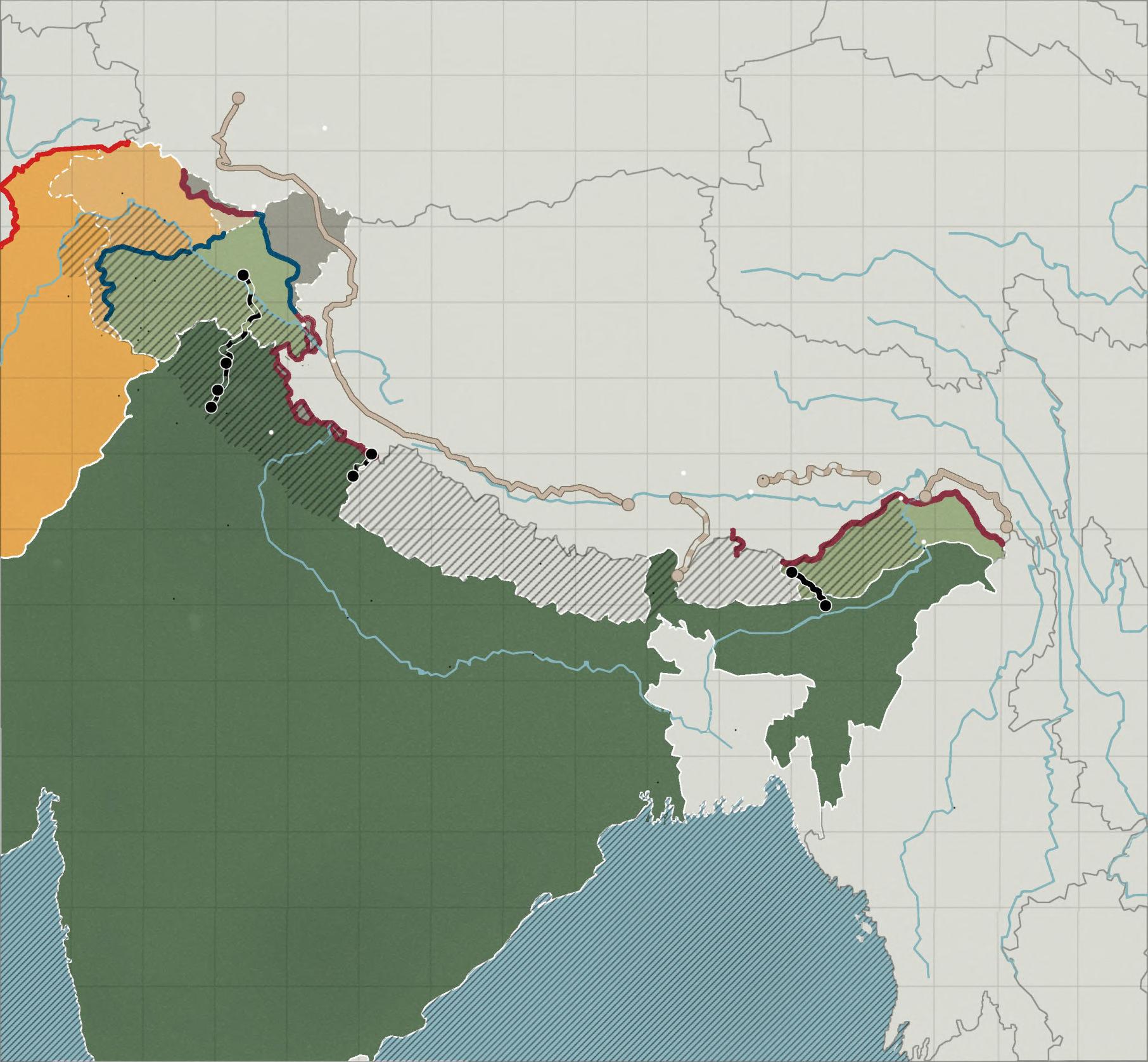
2.03 _ Wider Political Context

Disputed Himalayan Borders
N AFGHANISTANTAJIKISTAN KYRGYSTAN TIBET MYANMAR LAOSTHAILAND XINJIANG QINGHAI SICHUAN YUNNAN GANSU PAKISTAN DISPUTED BORDERS TRANSPORT INFRASTRUCTURE INDIA NEPAL BHUTAN BAY OF BENGAL BANGLADESH Area ceded by Pakistan to China Claimed by: India DURAND LINE DISPUTED BORDER LINES OF ACTUAL CONTROL Shigatse Yadong Railway Bilaspur Leh Railway China National Highway G219 DELHI KATHMANDU DHAKA ISLAMABAD Lahore Amritsar Shimla Dehra Dun Jaipur Kanpur Varanasi Patna Lhasa Pasighat Kolkata Darjeeling Lucknow Jammu Srinagar Kargil Leh Lhasa Nyingchi Railway Medog Zayu Road INDUS RIVER GANGES RIVER BRAHMAPUTRA RIVER “MCMAHON LINE” DISPUTED BORDER Siachen Glacier Claimed by: India and Pakistan Area held by China Claimed by: India Disputed Areas KEY Durand Line DisputedRoadsRoads Borders RailwaysRailways Airfields/Airbases Hotan AirportDaulat Beg LhasaOldi Gonggar AirportTuting Ngari Gunsa AirportFukche Nyingchi Mainling AirportPasighat Shigatse Peace AirportDharasu Airfields/Airbases Lines of Control India Pakistan Disputed Areas Siachen Glacier Himalayas Range JAMMU & KASHMIR Administered by India LADAKH KASHMIR Administered by Pakistan ARUNACHAL PRADESH Largely claimed by China 01 02 04 03 02 01 03 04 05 05 Ghatibagar Lipulekh Road TIBET/CHINAINDIA KEY 01 01 01 01 04 04 02 02 05 05 03 03
40
Figure 2.03A
As an extension of the study into the major peaks and ultras (with topographic prominence greater than 1500m/4921ft) distributed across the Himalayan mountain range, formed by the movement of tectonic plates, the mapping of major passes is a study into the man-made interventions used to navigate the foothold nature holds over the Himalayas.

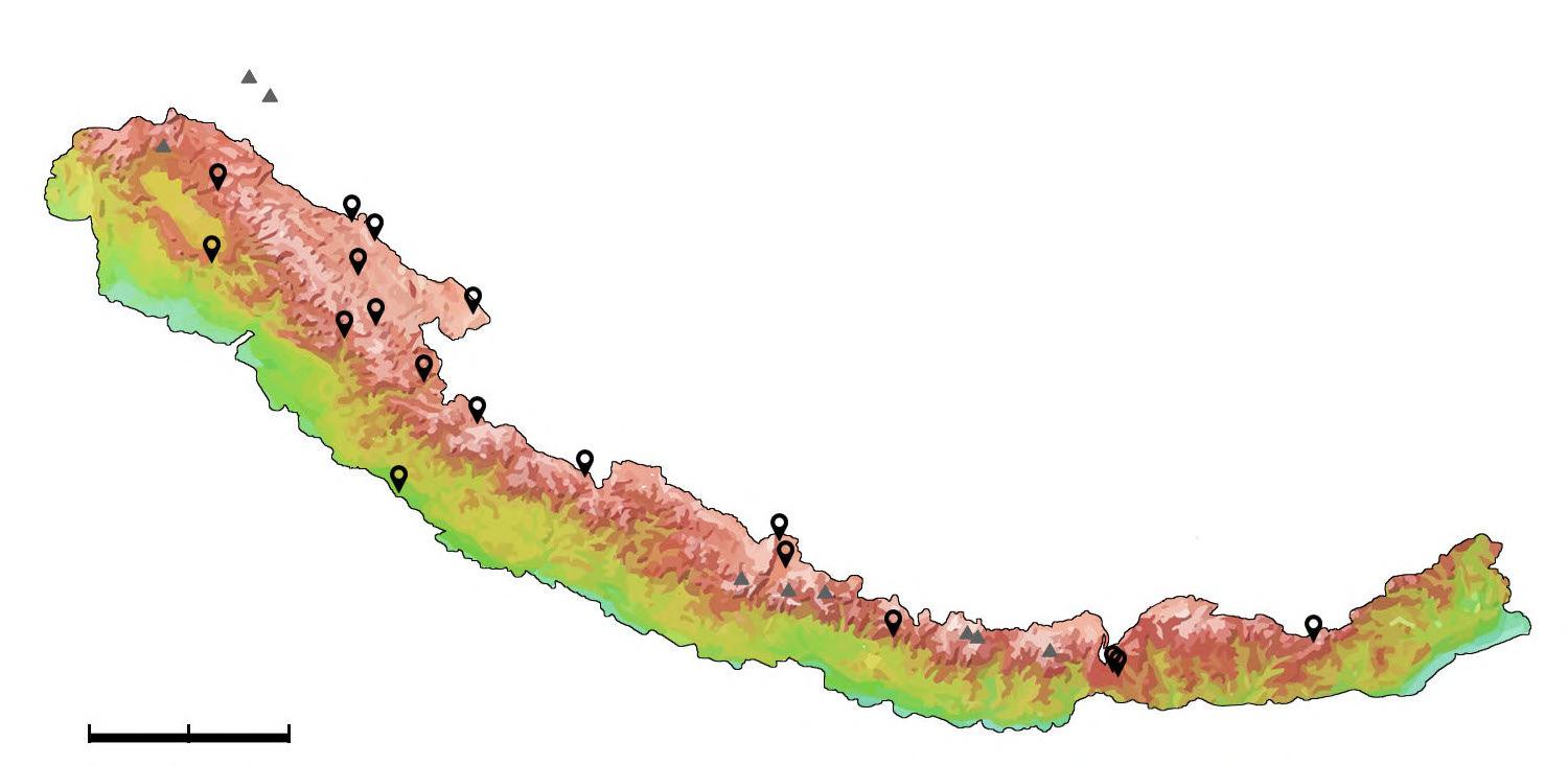
Although the terrain is extreme, some passes have been constructed as interventions for trade, vehicles and people.
Much of the passes are a direct response to the high footfall from tourists, largely in Nepal due to trekking and mountaineering expeditions.

In addition to the large mountainous coverage, glaciers occupy over 33000 sqkm of the Himalayas. The longest glaciers lie in Everest (Chomolungma) (up to 19km) and Kanchendzhanga (26 and 16km), in the Kumaon Himalayas. The glacier border ranges from 2500m in the lower region to 4000m in the central Himalayas.

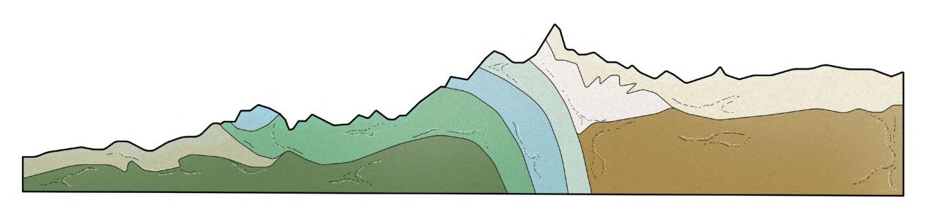
The main feature of the Himalayan geological structure are a series of flatlying overthrust plates (a reverse fault in which rocks on the upper surface move over the rocks on the lower surface) which moved from the north to the south, creating superposed folds, causing complex layered geometry, also called interference patterns. The cross section above through Mount Everest (Chomolungma) displays the onset of the tectonic processes of uplift, which create contrasting rock layers and mineral content, which are separated by faults and thrust boundaries. Zoji La Elevation: 11575 ft K2 Khardung La Elevation: 18373 ft Changla Pass Elevation: 16522 ft Bara-lacha La Elevation: 14600 ft Kunzum Pass Elevation: 15060 ft Sela Pass Elevation: 13862 ft Jelep La Elevation: 13950 ft Banihal Pass Elevation: 9291 ft Rohtang Pass Elevation: 13035 ft Mohan Pass Elevation: 5900 ft Umling La Elevation: 19301 ft Shipki La Elevation: 14764 ft Mana Pass Elevation: 18478 ft Lipulekh Pass Elevation: 14436 ft Kora La Elevation: 15072 ft Thorong La Elevation: 17769 ft ALTITUDE (M) GEOLOGICAL CROSS SECTION ACROSS 87° LONGITUDE HIMALAYAS IN CONTEXT 8300m Mount Everest 5641m 3062m 1411m 240m 13m Passes Locations Major Peaks Arniko Rajmarg Elevation: 17260 ft Nathu La Elevation: 14140 ft Kilometers 150 0 300 N NANGA PARBAT DHAULAGIRI ANNAPURNA MAKALU KANGCHENJUNGA MANASLU MT EVEREST GASHERBRUM Kantega Midlands Mahabharat Lekh Ganges Plain Siwaliks Indian Basement Nawakot Thrust Sheet Kathmandu Thrust Sheet Khumbu Thrust Sheet Tibetan Granites Tibetan Plateau Tibetan Basement Tibetan Sediments MAN-MADE INTERVENTIONS India Tibet China Pakistan Nepal Bhutan Bangladesh Myanmar
2.04 _ Wider Topography 41
Himalayan Passes
Figure 2.04A
Following increased population growth in the Himalayas since the 1960s, the large volume of persons per hectare has created increased strain on the landscape, putting pressure on farm land, forests and water resources. Within mountainous districts, the densities have caused more occupation on slopes, much of which is located on the hills and Terai region of Nepal, where annual population change exceeds 4% per year. Although the majority of dwelling in the Himalayas is rural, the percentage of urban dwellers has continued to increase.
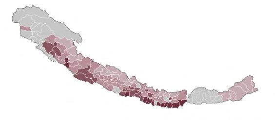
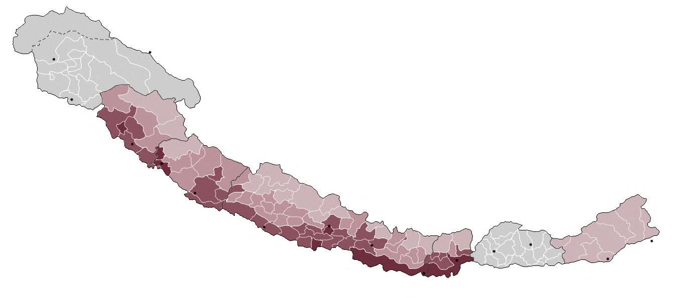
The flow of migration from countryside to the city has changed the urban fabric of many high-altitude towns. Dehra Dun, Shimla, Darjeeling and Gangtok are recent examples of Himalayan towns that have been urbanised, some of which were prominent locations of leisure for colonial British military officers during the summers, due to their cool climate in high altitude. Kashmir Valley contains one of the most populated towns in the Himalayas, Srinagar which has experienced modernisation trends - the onset of roads built for military use and hill stations during colonialism.
DENSITYMIGRATION
URBANISATION India Tibet China Pakistan Nepal Bhutan Bangladesh Myanmar Leh Population (2011): 30 870 Pokhara Population (2011): 264 991 Bumthang Population (2017): 17 820 THIMPHU Population (2011): 114 551 Jammu Population (2011): 502 197 Dehra Dun Population: 569 578 Nainital Population (2011): 41 377 Nepalgunj Population (2017): 138 951 KATHMANDU Population (2011): 1 003 000 1 810 000 1 003 000 569 578 502 197 264 991 169 578 154 019 138 951 17 820 30 870 41 377 59 490 114 551 120 414 Birlanagar Itanagar Population (2011): 59 490 Dibrugarh Population (2011): 154 019 Darjeeling Population (2011): 120 414 India Nepal Bhutan Srinagar Kathmandu Dehra Dun Jammu Pokhara Shimla Dibrugarh Nepalgunj Darjeeling Thimpu Itanagar Nainital Leh Bumthang Shimla Population (2011): 169 578 Srinagar Population (2011): 1 810 000
HIMALAYAS IN CONTEXT POPULATION
AND
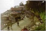
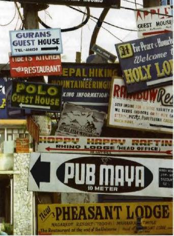
NEPAL UTTARAKHANDSIKKIM BHUTAN ARUNACHAL PRADESH HIMACHAL 02PRADESH04 0107 01 02 03 04 0506 07 0305 06 JAMMU AND KASHMIR The modernisation trends in the Himalayas has created increased demand for tourist amenity, cannibalising the landscape to a commercialised extension of modern day activities. The expeditions that culminate in the Himalayas as the ultimate destination, have provided an economical footboard for the region, ranging from the colonial landscape of Shimla to the signage dominated lodges in the urban areas of Nepal (location of Mt. Everest).
CANNIBALISED LANDSCAPE POPULATION BY RANK Very High (>3) High (1.5-3) Medium (0.5-1.49) Low (0-0.49) Insufficient Data LeisureReligiousCivicCommunityOffices Raj Bhatwan (Peterhoff) Kilometers 150 0 300 N 19611981 2001 Shimla Expanding Urbanism 2.05 _ Himalayan Inhabitation 42
KEY(PERSONSPERHECTARE)
Figure 2.05A
2.06 _ Expanding Urbanism & Wider Economy Summary
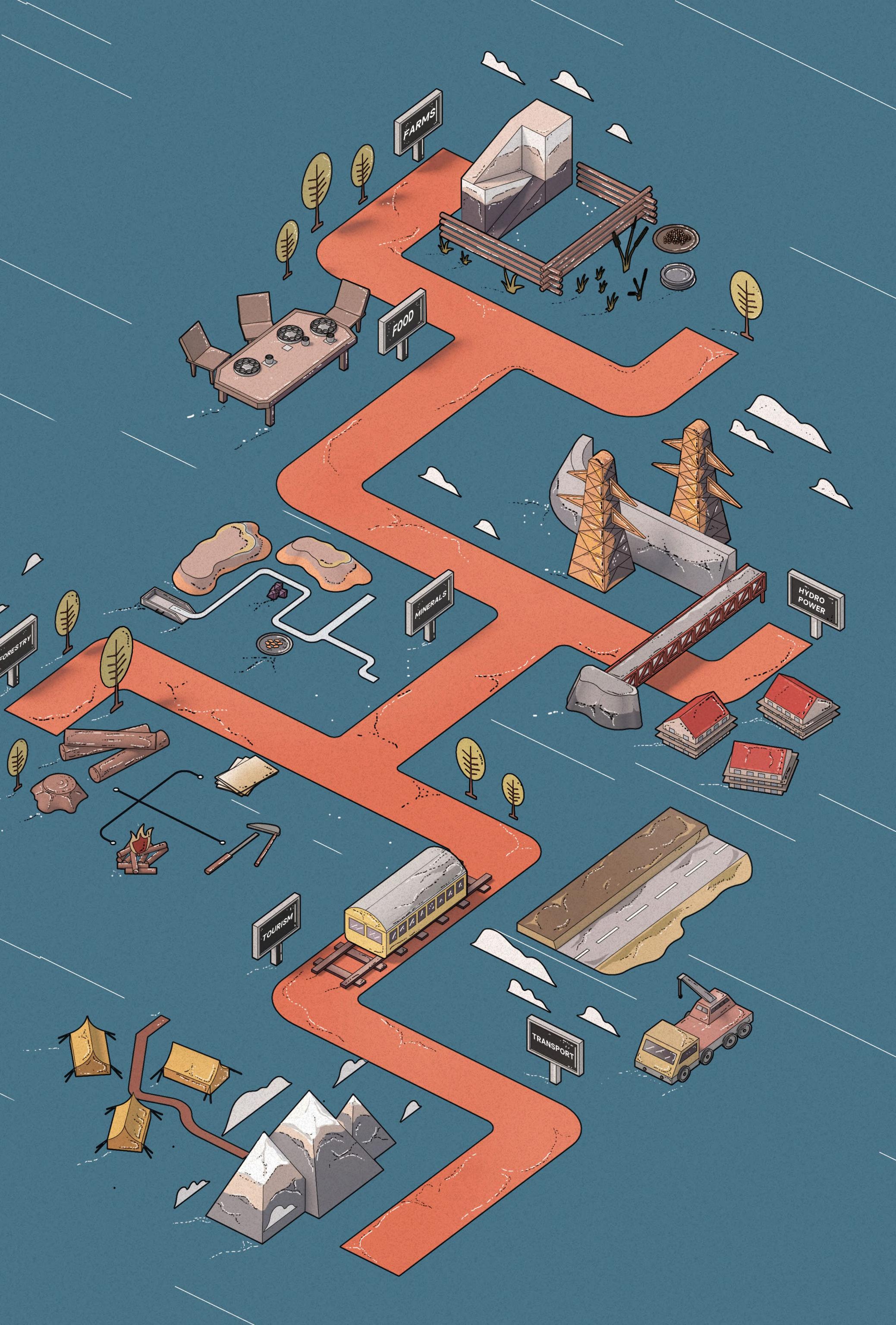
Himalayan Infrastructure
MINERAL DEPOSITS
LOCATIONMINERAL
ZASKAR
MOUNTAIN RANGE
INDUS RIVER
BALISTAN
KASHMIR
LADAKH
JAMMU HILLS
NEPAL
BHUTAN SIKKIM, INDIA
FORESTRY
Sapphires
Alluvial Gold
Copper Ore
Iron Ore and Bauxite
Borax and Sulfur
Coal Seams
Coal, Mica, Gypsum, Graphite, Iron, Copper, Lead, Zinc
FOOD EXPORT
Fruits from Kashmir and Himachal Pradesh are exported to cities in India, as well as grapes used for wine and brandy. Bhutan also exports oranges to India.
Tea is grown in Darjeeling, and spice cardamon is found in Sikkim & Bhutan.
HYDRO-POWER
Capacity for Hydro-power first harnessed in India
Reservoir at Bhakra-Nangal on Sutlej River completed in 1963 with storage capacity of 10 billion cubic metres of water and generating capacity of 1050 megawatts
Nathpa Jhakri Dam on Sutlej Valley, Himachal Pradesh and Rampur Station operational Nepal and China have constructed hydropower projects in the Himalayas, with the Zangmu Station on Yarlung Zangbo (Brahmaputra) River completed in Tibet in 2015
FARMING

Sheeps, goats and yaks are grazed at higher elevations and migrate to lower levels during cold weather.
Arable lands in the western Himalayas are in the vale of Kashmir, Kangra valley, the Sutlej Valley Basin, and the periphery of the Ganges and Yamuna Rivers in Uttarakhand, producing rice, corn (maize), wheat, and millet.
The central Himalayas produces corn, wheat, potatoes, and sugarcane.
TOURISM
Nepal largely relies on tourism as a sourc of income, including from mountaineers looking to climb Everest. However, this caused increased traffic and tourists’ consumption of the region’s limited resourc causing further stress on the environment.
Sikkim and Bhutan are large regions heavily forested, with land used for planting to supply firewood, paper and construction materials.
RAILROADS
One major railroad connects Kalka and Shimla in the western Himalayas, while the second connects Siliguri to Darjeeling in the eastern Himalayas.
A narrow gauge line in Nepal runs 30 miles from Raxaul, Bihar State, India to Amlekhganj.
Two shorter railroads run to the outer Himalayas, one from Pathankot to Jogindarnagar in Kullu Valley and the other from Hardiwar to Dehra Dun.
CARAVAN TRADE ROUTES
The Sikkim Himalayas use the historic Kalimpang-to-Lhasa trade route which passes through Gangtok. Several roads passable via four wheel drives have been built in southern Sikkim, with the highway from Siliguri having been extended through Lachung in northern Sikkim to Tibet.
The Kosi, Gandak and Jaldhaka Rivers were harnessed by India to supply electric power to Nepal and Bhutan.
AIRPORTS
Two major airstrips in the Himalayas are located in Kathmandu and Srinagar, with Kathmandu’s airport servicing international and regional flights. Increased road and transport infrastructure has expanded the growth of tourism in the Himalayas.
ROAD CONNECTIONS
Many new roads have been built since 1950, connecting several territories across the Himalayas.
KATHMANDU
NEPAL PAKISTAN
HIMACHAL PRADESH
MANALI PUNJAB
Low Himalayan Highway
via Kodari Pass
Karakoram Highway
Hindustan-Tibet Road
POKHARA, TIBET
BIHAR STATE INDIA
CHINA
TIBET
Srinagar, Kashmir via 5404m Khardung Pass
Highway Connection
Highway Connection
480km via Shimla and Shipki Pass via Jalandhar to Srinagar
LEH
KASHMIR
01 02 03 06
INFRASTRUCTURE
INFRASTRUCTURE
INFRASTRUCTURE
TRANSPORT
TRANSPORT
TRANSPORT
TRANSPORT INFRASTRUCTURE
1950S 1963 2014 2015 05 07 08 10 09
source mountaineers has heavy resources, environment. 04 09 07 10 08 06 05 04 03 02 01 44 BARC0174 _ AAD1CHAPTER 2A _ WIDER SITE CONTEXT
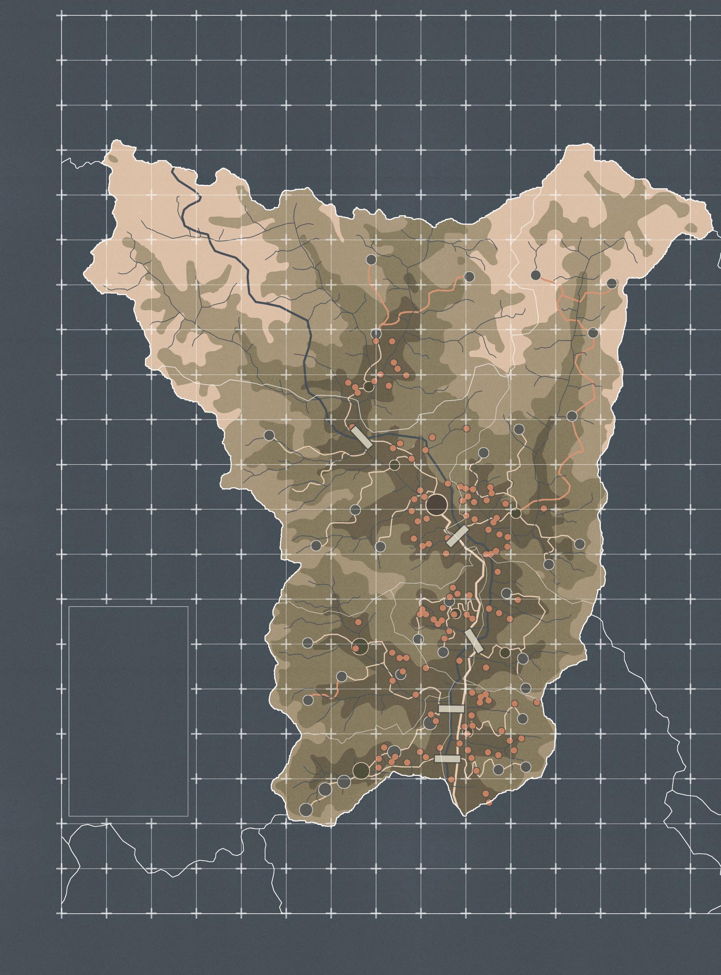
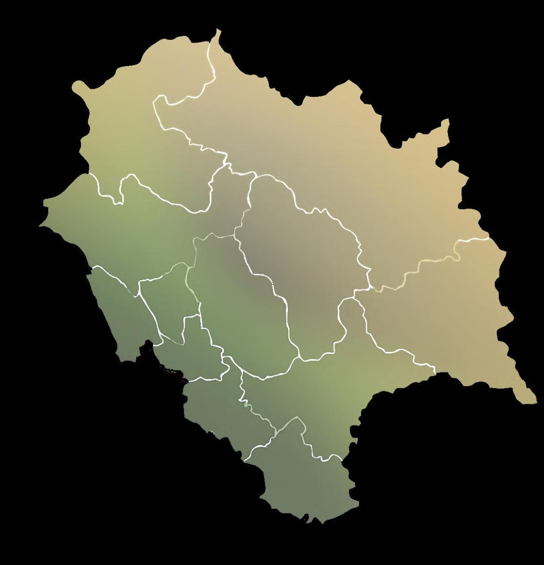
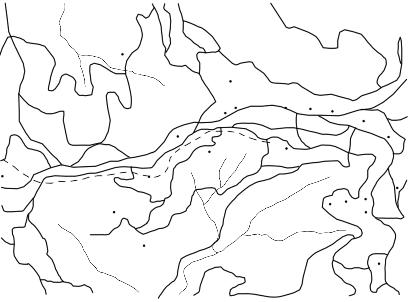
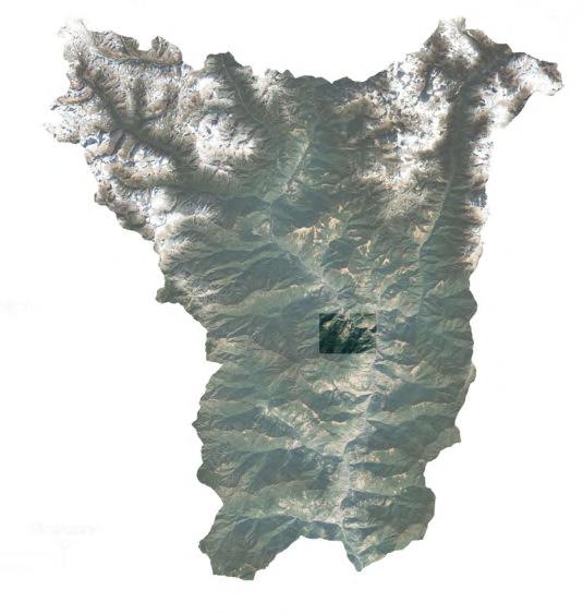
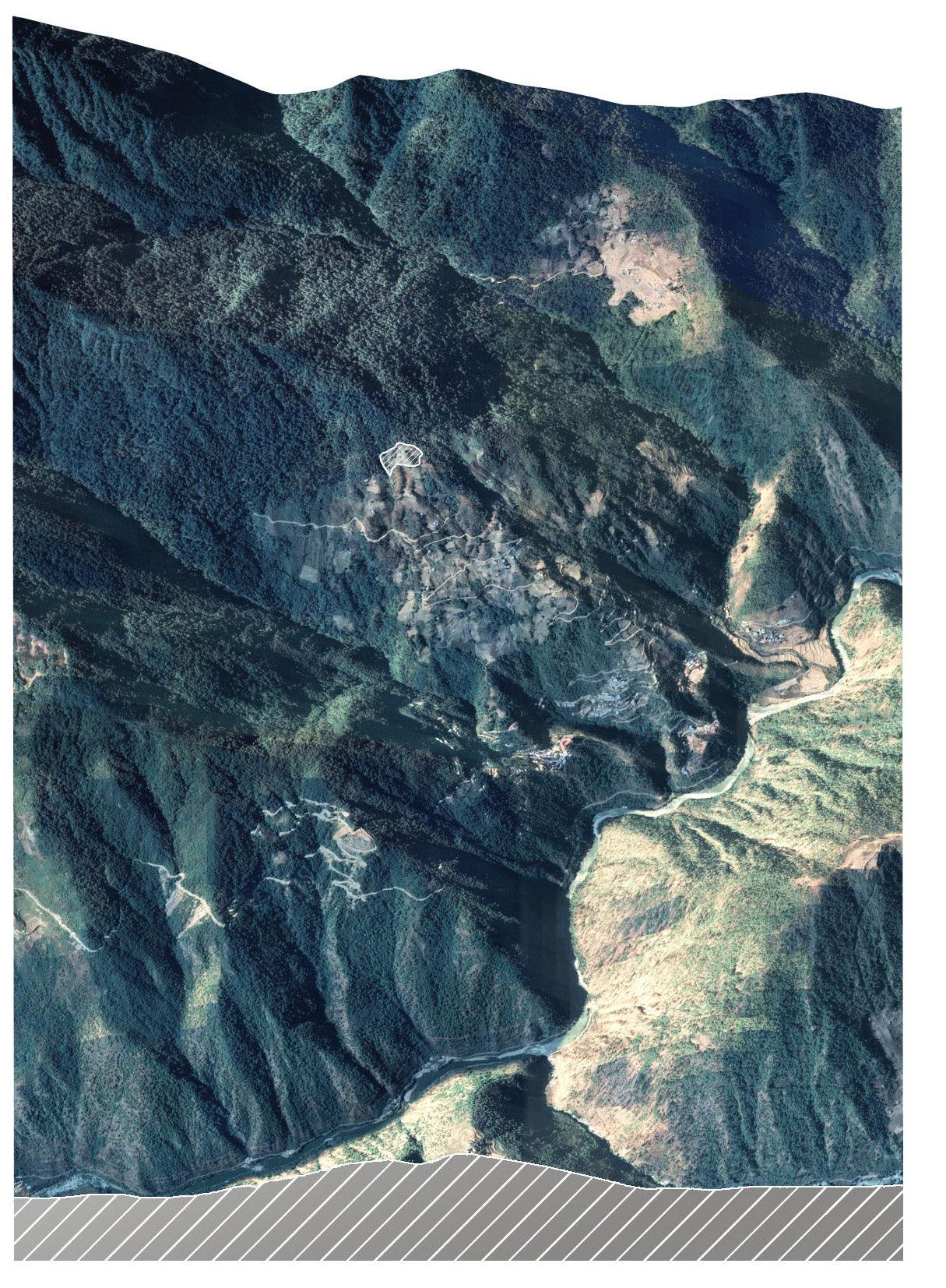
N 0m100m GANGZUR KURTOED KHOMA MINJEY TSAENKHAR JAREY MAEDTSHO MAENBI KEY Main Highway Feeder Road Kuri Chhu River Rivers Foot Path Lhuentse Dzong & Site Location Bridge Gewog Centre Village Historical Sites SITE TIBET TASHI YANGTSE MONGAR BUMTHANG
Lhuentse DistrictBhutan
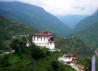
Site Overview:
LHUENTSE TOWN, LHUENTSE DISTRICT, BHUTAN
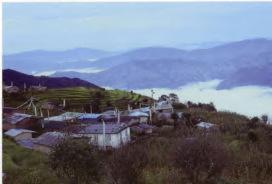
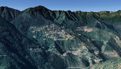
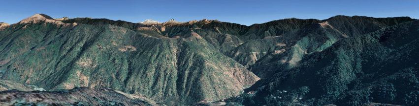
Having identified Bhutan as an insular and never before colonised nation in the Himalayas, the chosen site in eastern Bhutan presents an opportunity to preserve the nation’s cultural heritage and identity whilst engaging both locals and tourists within a rural, but moderately urban context. The remote site is located nearby a cluster of historical spots in the ancestral homeland of the Bhutanese royal family in Lhuentse Town, the headquarter of Lhuentse District, whilst providing vast views across the high altitude town.
Brief Ambition: CRAFTS: A CIVIC & EDUCATIONAL OPPORTUNITY
The scheme seeks to consolidate Lhuentse Town’s reputation for textile/crafts production and its existing exposure to tourists/campers, aiming to introduce an educational programme for both local/ foreign users, creating a civic presence with a hybrid structural expression, materialising a novel cultural exchange.
02B BARC0174 _ AAD1CHAPTER 2 _ HIMALAYAS, ABODE OF SNOW
SITE AND BRIEF

Lhuentse Town, Bhutan 46
Lhuentse, Bhutan
LHUENTSE TOWN

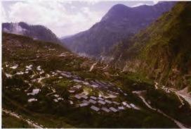
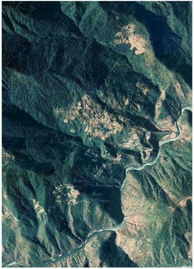
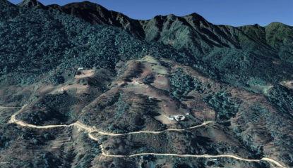
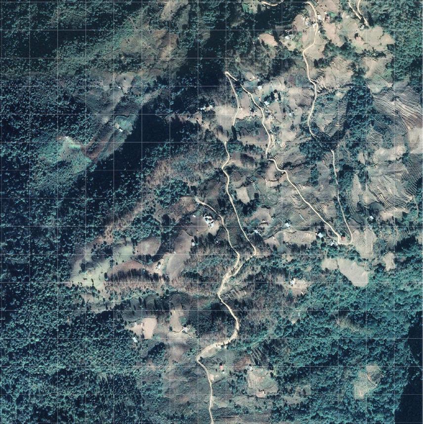
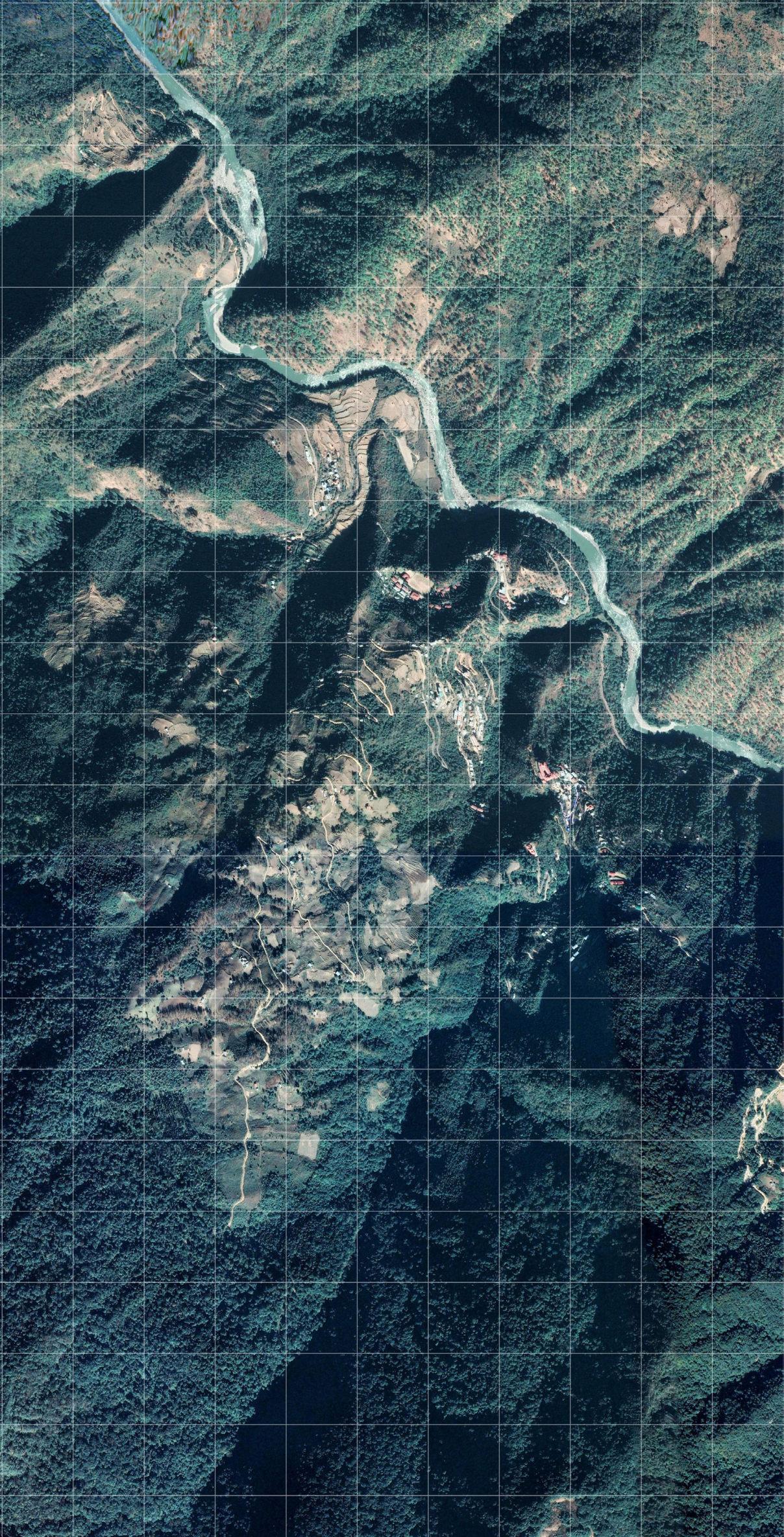
The site is located at high altitude with a vantage point over the town of Lhuentse in Lhuentse District, the headquarter of the district. Located 450km east of Bhutan’s capital Thimpu, the site is in the gewog (county) of Gangzur. The proposal for a citadel of culture/craft seeks to propel footfall in the remote district, and consolidate the existing infrastructure problems including poor electricity distribution, and the difficult terrain, which makes social welfare access a challenge.
Chorten
Views 2 & 3 - Looking towards site View 1 - Looking out of site INHABITED CONDITIONS SITE CONTEXTWIDER VIEW 1 VIEW 1 VIEW 2 VIEW 3 VIEW 2 SITE CONTEXT VIEW 3 KEY
300m100m 100m0m200m500m1000m
Lhuentse Town Boundary
Gangzur Village Kuru Chhu River
Gadongla Tshongkang
Lhuentse Dzong
Bhutan SITE SITE N N
LHUENTSE DZONG Dzongs monasterie Bhutan Lhuents a a offices, ac specifically Tibetan as of also focussing sky the will this main N N
Lhuentse Court Bank of
SITESITE LHUENTSE DZONG LHUENTSE COURT
2.07 _ Site
Figure 2.07A
Dzongs are fortified monasteries, of which Bhutan contains many.
Lhuentse Dzong wraps central courtyard with temple, administration offices, and monks’ accommodation. It is a specifically Bhutanese/ Tibetan typology, behaving as the main civic centre the district. Large walls also obstruct lateral views, focussing attention to the sky (and the symbolism of the heavens). The scheme will seek to consolidate this landmark as well as its main conditions.
LHUENTSE COURT (CIVIC)
BANK OF BHUTAN (CIVIC)
LHUENTSE BACKGROUND
The site is moderately urban, yet still remote, as well as the ancestral homeland of the Bhutanese royal family. The site’s terrain and characteristics attract campers, making the site a potential mediator of such activity, creating an opportunity for cultural exchange.
This creates the possibility for structural expression referencing Kath Khuni, materialising a hybrid cultural architecture.
DZONG CONTOUR MAP
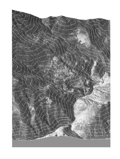


The scheme also seeks to mediate the environmentally protected areas and capture expansive views of the landscape steeped in myths and historical sites dotted across the terrain.
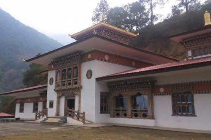
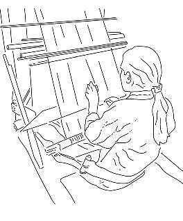
Lhuentse Town is well known for textile production, a significant aspect of Bhutanese culture. Weavers use looms to craft garments of clothing distributed across Bhutan. The scheme seeks to preserve the tradition of Bhutanese textile production, and create more visibility outside the nation.
WINDING ROAD CREATES ACCESS POINT
GANGZUR VILLAGE
CHORTEN
LHUENTSE DZONG (CIVIC)
KURU CHHU RIVER
Meters 1005001000 0 N SITE SITE
The site sits at a high altitude of approximately 2190m (7185ft). An existing road creates an access point, and an overlooking position across the town.
48 Bhutan Nepal Tibet India BARC0174 _ AAD1CHAPTER 2B _ SITE AND BRIEF
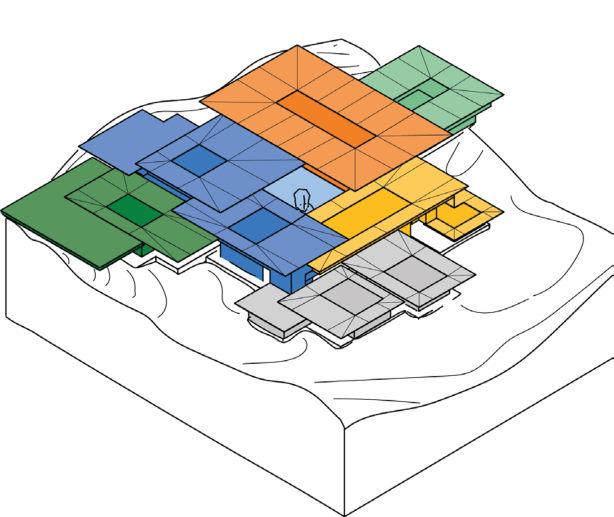
Lhuentse School of Crafts
DESIGN PROPOSAL
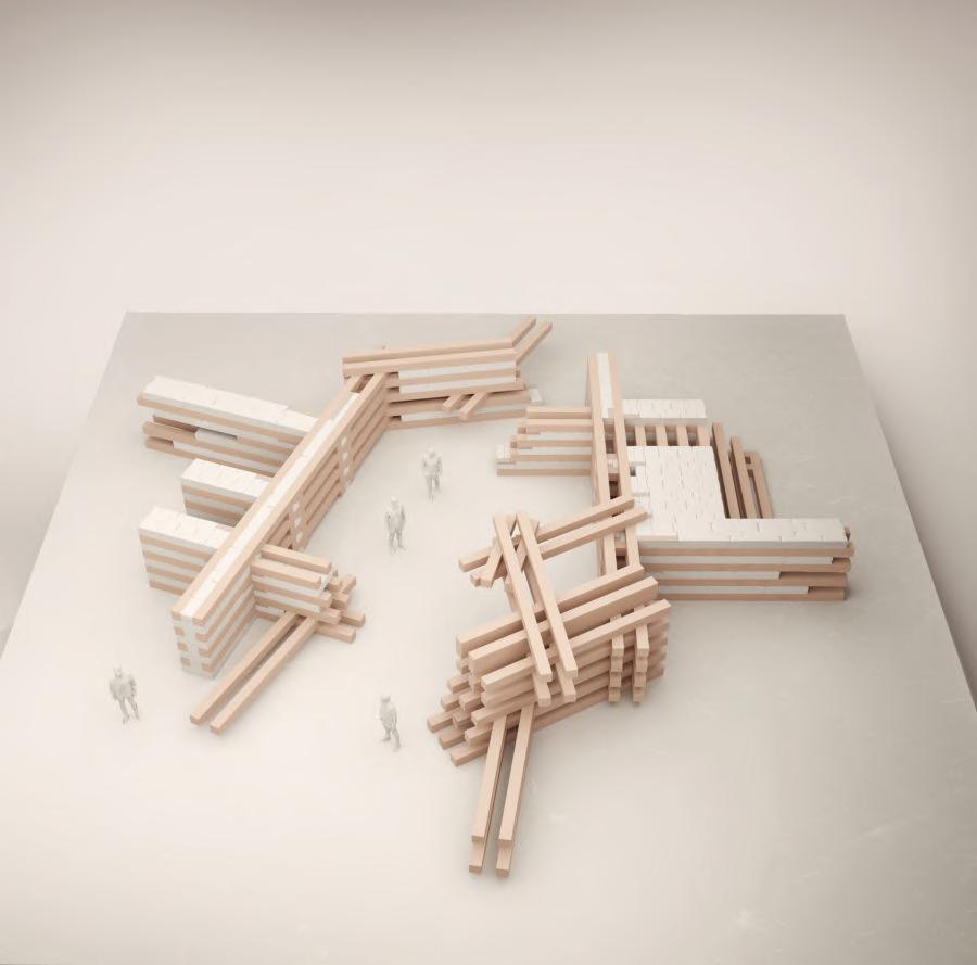
Using the research into Kath Khuni construction as a schematic basis, the proposal speculates on the possibilities of this material hybrid in the remote context of Lhuentse in eastern Bhutan, a nation caught between the push of modernisation and the maintenance of its unique cultural heritage. Through the introduction of a crafts based, higher educational programme, the scheme seeks to consolidate Lhuentse’s textiles industry with a hybrid user group of foreign exchange students and native craftspeople. Programmatically, the campus explores three primary Bhutanese crafts including carpentry, textiles and painting, and reconsiders traditional modes of sleeping and dining, outside of a central courtyard.
Carpentry Workshop Painting WorkshopDormitories
Textiles WorkshopDining/AuditoriumCentral Courtyard
Grey shows the main entrance and security zones, behaving as a public information point to the campus. hierarchy.
Carpentry Workshop
01.02.
Taught by Bhutanese master craftsmen known as Zo Chen/ Zo Wo, students learn the intricate and ornate techniques of Bhutanese Shingzo (carpentry), using a mix of both traditional and contemporary machines including lathes, chisels, hammers and bandsaws.
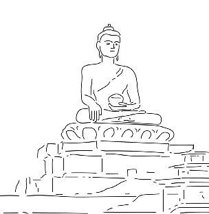
Central Courtyard
Behaving as the main point of contact between students and staff, the central courtyard acts as a combined outdoor workspace/exhibition space. A large central Buddha sculpture consolidates the nation’s Buddhist symbolism whilst exhibiting its real time construction process onlookers.
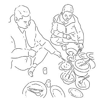
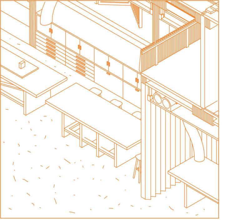
Dining/Auditorium
A multipurpose large dining room/ auditorium creates a communal gathering space for Bhutanese people and foreign students. Locally sourced foods, sitting and eating practices engages existing and historic local practices.
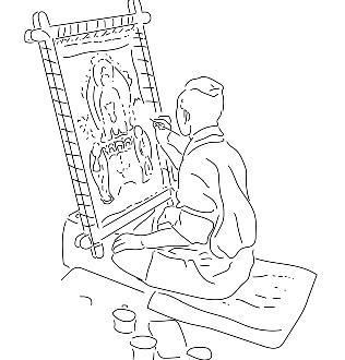
Painting Workshop
03.04. 05.06.
Master painters known as Lharips teach students to paint murals and frescoes using traditional religious symbols, deities and icons, using a restricted palette of mainly blacks, reds and yellows.
Dormitories
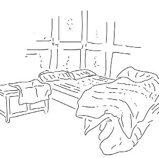
Sixteen rooms with 1, 2, 4 and 8-bed provisions for staff and students across two stories provide 86 beds for relaxation and socialising, creating the same sense of enclosure and domesticity as Bhutanese dwellings.
Textiles Workshop
Using rich vibrant colours, intricate dyeing, and manual weaving techniques, traditional looms are used to craft textiles, acting as a continuation of one Bhutan’s oldest crafts.
2.08 _ Brief & Programme
Figure 2.08A
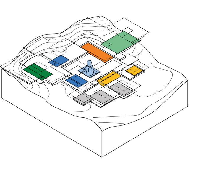
Using three of Bhutan’s thirteen traditional arts and crafts as a programmatic framework (shown above) - carpentry, painting and weaving create the most global reach, creating a strong transferable skillset for foreign students to practice following completion of their respective courses. The building’s campus typology creates a series of courtyards that interweave between workshop spaces, engaging the local context, and morphologically, create a visual hierarchy of rectilinear, outwardly pixelating volumes. Each of these conditions contribute to a hybrid cultural exchange between Bhutan and the rest of the world.
Using foreign student fees as a source of income for the campus and Bhutan, the scheme speculates on Bhutan becoming a less insular nation through education, rather than tourism, to prevent their fear of becoming over-commercialised. This invites foreign students to engage more closely and strongly with the culture.


An adaptation of Kath Khuni construction creates a cross-cultural structural strategy for the building, engaging influences from both the western and eastern Himalayas.

50
A HYBRID CIVIC IDENTITY
Programme - Consolidating Three of Bhutan’s
Traditional Arts and Crafts
Chusum) Typology & Morphology Shingzo Carpentry Dozo Masonry Parzo Carving Lhazo Painting Jinzo Sculpting Lugzo Bronze Casting Garzo Blacksmithing Troeko Ornament Making Tsharzo Cane & Bamboo Weaving Thagzo Weaving Tshemzo Tailoring Shagzo Woodturning Dezo Paper-making
Thirteen
(Zorig
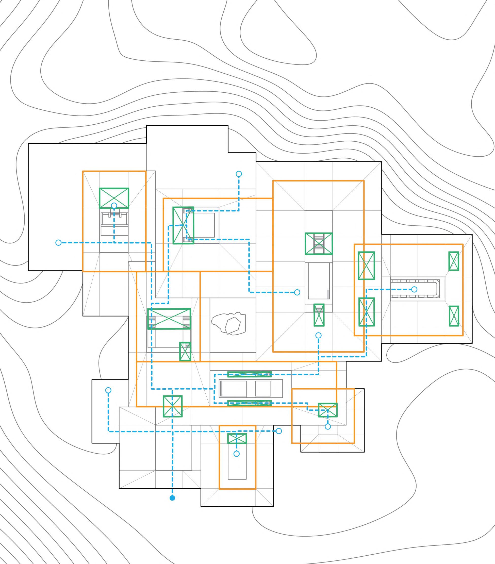
Cultural Exchange Buddhist for SCHEMATIC PLAN same domesticity textiles, of Hybrid Construction Local Religious Symbolism Increasing capital for Bhutan Traditional/Contemporary Exchange Stairs/Lift Access 03 01 02 05 09 07 08 04 06 DINING / AUDITORIUM 687 m2 TEXTILES 01 638 m2 TEXTILES 02 1077 m2 SECURITY 286 m2 PAINTING 01 169 m2 PAINTING 02 761 m2 DORMITORIES 1080 m2 ENTRANCE 610 m2 CARPENTRY 1710 m2 Roof Plan Indicative Upper Storey (approximate surface area indicated) Proposed Circulation Route 2.08A
BARC0174 _ AAD1CHAPTER 2B _ SITE AND BRIEF
Figure 2.08B
Deliveries & Sourcing
PLANNING STRATEGY
The building’s main premise relies on an initial startup meeting between foreign and local architect planners and the Bhutanese government. Bhutan’s Ministry of Home and Cultural Affairs oversees 20 dzongkhags (local governments) across Bhutan, of which the campus sits in the dzongkhag of Lhuentse. This local government will behave as the review board and will appoint the project team, alongside the foreign architect/planners. They will also fund the project. Following the building’s completion, fees will be charged to foreign students to attend courses at the school, allowing the project to pay itself off and increase returns for Lhuentse’s dzongkhag. This aims to generate increased capital for the town and district, to stimulate improved social and economic welfare whilst speculating on the impact of foreign capital for the relatively insular nation of Bhutan.
Project Delivery Overview
Approval of government fund by Bhutan’s Ministry of Education to develop infrastructure to benefit the community & economy.
Government Funding
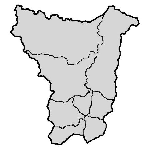
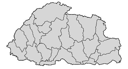
The Kingdom of Bhutan is divided into 20 districts, known as Dzongkhags (borders shown below). The campus sits in the Dzongkhag of Lhuentse (or Lhuentse District). As one of the least developed districts in Bhutan, the scheme seeks local funding from the Dzongkhag to create increased footfall, and propel infrastructure including electricity, roads and gas stations, for the benefit of over 2000 households in the district.
Building Compliance
Bhutan Building Rules
Bhutan Five Year Plan

Bhutan’s Department of Urban Development & Housing sets out a series of requirements during the planning and submission stages for construction projects in Bhutan. This document is known as Bhutan Building Rules (an earlier version dated to 2002 is shown above). The campus aims to follow the document’s guidance on planning permission, change of building use, providing coverage for parking areas, and a suitable architectural design.
Phase 1 - Preparation & Briefing
- Establish project team & define brief
- Start up meeting & design team appointed
- Costs estimated
- Project coordination
- Client review
Phase 2 - Concept Design
- Concept design delivery & production
- Concept design deliverables issued
- Material selection & sourcing identified
- Site survey
- Lhuentse Dzongkhag consultation
- Scale prototyping
- Finalise brief
- Consultants & architect appointed
Phase 3 - Design Development
- Construction Manager appointed
- Planning application submitted
- Initial costing
- Quantity surveyor


Phase 4 - Technical Design
- Tender packages submitted
- BIM Model
- Facade Mock-up
Phase 5 - Final Project Approval
- Planning submission to Dzongkhag administration
- Planning Approval
Phase 6 - Manufacturing & Construction
- Material quantity determined
- Liaison with local parks and supply routes created
- Materials procured and delivered
- Pre-fabricated elements delivered
- On-site fabrication and assembly
- Internal fit-out
Phase 7 - Handover & Use
- Building construction complete
- Building opened to staff and students
- Building use and maintenance begins
Planning Approval following building compliance with Bhutan Building Rules set by Department of Urban Development & Housing.
Liaison with Department of Forest and Park Services for safe logging and delivery of materials, outside of conservation areas.
Temporary accommodation provides housing for local labour force and foreign students during initial construction phase.
2.09 _ Planning Strategy
DESIGN TIMELINE
S 202220232024 JMJMSNMJMJNOFJFJODAAAAD On-site pre-fabrication & testing 01 02 Figure 2.09A
Beginning in 1961, Bhutan’s 12th Five-Year Plan (2018-2023) aims to free the nation from social and economic disruption through an emphasis on Gross National Happiness (GNH), which the scheme considers.

Timber Sourcing

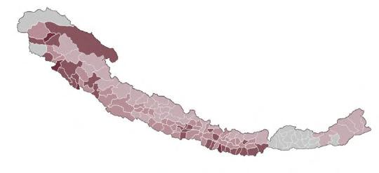
Bhutan’s Department of Forests and Park Services conserve and manage Bhutan’s forestry resources. The department has used several pieces of policy and legislation to control the use of forest land for construction. Planting trees whenever one is cut down ensures that a minimum of 60% of the nation remains covered by forest, contributing to Bhutan’s carbon negativity. Lhuentse District contains a rich resource of forests, which also ensures a renewable source of energy for future generations.
Protected Areas of Lhuentse District
Protected Biological Corridors

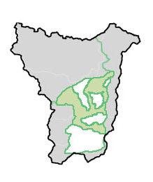
Protected ParksNational Parks

Site Location


Bhutan’s Department of Forests and Park Services


Following completion of building construction, the campus is opened to staff and students. Building use and maintenance begins. 2025 SJNMOFDAA
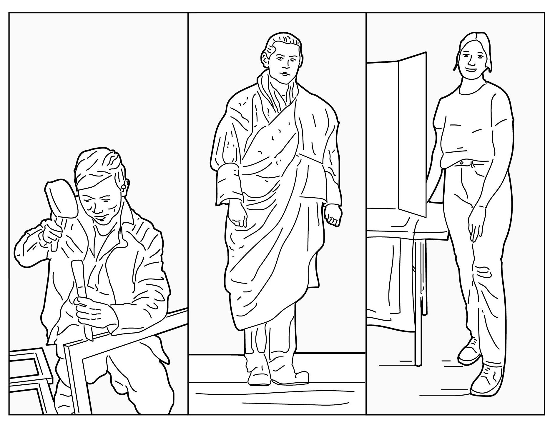
User Group


Initially funded by the Bhutanese government to realise the project, the campus becomes a civic destination for incoming students, who are taught by expert local craftspeople. This reframes the overly spiritualised lens of the Himalayas, and creates a productive educational programme for the benefit of both the local people and foreign students.
On the right diagram, shown in light grey are parks in Lhuentse District including Wangchuk Centennial Park (1) in the north and Thrumshingla National Park (2) in the south. Each of these parks are connected by protected parks and protected biological corridors which allow the opportunity to locally source wood for the campus. This may then be transferred to a local factory prior to delivery to site (illustrated right). This would follow government guidance.
Widened Higher Education

The campus consolidates Bhutan’s position in a constantly modernising world, by introducing a crafts based educational programme that combines contemporary and traditional methods of carpentry, textiles and weaving:
The scheme relies on income from foreign exchange students to break even and make profit for the scheme’s construction, opening Bhutan to foreign relations for the relatively insular nation, whilst expressing the nation’s Buddhist religion and values.

A consortium of existing institutions of higher education in Bhutan, many of which fall under the umbrella of the Royal University of Bhutan (founded by Royal Decree) are largely used by Bhutanese students. Most offer courses based in engineering, sciences, law and business. This invites the opportunity for the study of a creative discipline.


Falling under Royal Decree, LSC (Lhuentse School of Crafts) sits in eastern Bhutan (the majority of institutions are currently based in the west), opening up both social and economic benefits for the local community and government.

52
Buddhist ReligionBhutan’s Global Reach Income through Foreign Exchange LSC A A B B C C
01. 02.
01. User 1 Bhutanese Craftspeople as Teachers
02. Client Bhutanese Government
0102
03. User 2 Local & Foreign Exchange Students
Figure 2.09B
Figure 2.09C
Figure 2.09D
BARC0174 _ AAD1CHAPTER 2B _ SITE AND BRIEF
Figure 2.09E
Using the local government of Lhuentse (Dzongkhag) as guarantors for the project’s funding, the Royal University of Bhutan behaves as an umbrella organisation that funds the delivery of Lhuentse School of Crafts (which is later incorporated as an affiliate college of the university). The state acts as a guarantor for loan agreements (through its national bank) between the Royal University of Bhutan & India (Bhutan’s largest creditor) where the state borrows capital for the building’s construction, expecting the profits made to be greater than the interest payable. Loans are repaid via student fees paid to the Royal University of Bhutan and the contractor.

A design and build contract also offers more agency to local craftspeople, allowing them to be brought into the project at an earlier stage. A project manager is responsible for the coordination of foreign architect planners, consultants and local contractors (and craftspeople), assisting with drawings, site visits, surveys, budgeting and feasibility studies. This procurement method also allows construction to begin without a finalised design via mockups and material testing.
Fulfilling Bhutan’s Five-Year Plan


By sustaining public finance on an even level, and using a lean bureaucracy, the contract aims to use traditional social institutions to engage local people in the project’s planning and implementation.
Sustaining Carbon Negativity
As the only carbon negative nation in the world, the building’s use of local resources ensures the continued management of the nation’s forests and the renewable hydro-electric power sources.
Gross National Happiness


The building’s culture-specific programme fulfils Bhutan’s emphasis on the concept of Gross National Happiness (as opposed to Gross Domestic Product), giving equal importance to non-monetary aspects of personal well-being.
DESIGN & BUILD CONTRACT
A design and build contract provides both architect and contractor services. It ensures clear organisation, planning, communication and control at every stage of the delivery process. This aims to create a more efficient relationship between client and contractor, and use local contractors’ expertise during construction.
Economic & Social Benefits Contracts & Procurement Section 2.10 53
Lhuentse Dzongkhag (District) State Owned Consortium Overall Contractor Contractor Performance of Client Role Design & Build Contract ArchitectsSub-Contractors Client Project Manager Consultants Cost Consultant Contractor Sub-Contractors Architect Engineers Consultants Operations & Maintenance CreditorsCreditors Royal University of Bhutan Royal University of Bhutan Public, decentralized university Public, decentralized university India (Bhutan’s largest creditor) India (Bhutan’s largest creditor) Lhuentse School of Crafts Fees Absorbed as affiliate college of the Royal University of Bhutan A combination of foreign and local architects are appointed throughout the contract. Appointed during the contract, sub-contractors are responsible for certain on-site works. Appointed throughout the contract, engineers are involved throughout the design process. A team of consultants are appointed throughout the contract. RepaymentsRepayments Construction Contract Services Contract Works Contract Operations & Maintenance Contract Bhutan Department of Higher Education
ClientClient
CONTRACTS & PROCUREMENTS
LSC
LoansLoans
State Guaranteed CapitalState Guaranteed Capital
CLIENT & FUNDING


As shown on the previous page, a state owned consortium performs the client role on behalf of both Lhuentse Dzongkhag (local government) and the Bhutan Department of Higher Education. The completed building will be incorporated into the Royal University of Bhutan as an affiliate college, hence they also behave as a client. The project will be funded primarily by the Bhutanese government, with India’s banks behaving as creditors. The project aims to make a profit for Bhutan and its local government through student fees, charged at $2 800 per year for Bhutanese students (approximate based on existing fees for Bhutanese universities). Foreign students from nearby nations will be charged twice this figure, and those from further afield, based on a tier system, three times this figure. In comparison to UK universities, the fees will be considerably lower, whilst still aiming to generate a significant long-term profit. This intends to help boost Lhuentse and Bhutan’s social and economic welfare.
Local Government & Education
State financial backing throughout the project will ensure GNH is considered.
Local & Foreign Students
Public consultations will ensure local and foreign students can contribute to the building’s social and economic welfare.
Local Residents & General Public
Nearby residents and the Bhutanese public should be consulted throughout, with public consultations, contributing to the building’s civic identity.


PROJECT DELIVERY TEAM
To help coordinate information between different teams and consultants, Building Information Modelling (BIM) can be used throughout the design process, from the initial concept design phase through to construction and operation. Using a software like Revit, different simulations can be explored and tested, for the benefit of every team, to ensure the quick and efficient transfer of information.
Overall Contractor


Project Manager


Central BIM Model
Coordination of Information


Section 2.11 54 State Owned Consortium Responsible for Client Role Main Board Advisory Board
Key Stakeholders Roles & Responsibilities
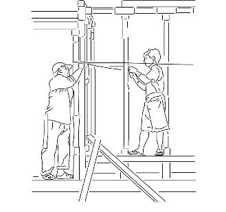
Local Craftspeople Local Architect Lead Architect Delivery AnalysisStructural Simulations Environmental Simulations Landscape AnalysisFacade Simulations MEP Engineer Delivery Contractor Interior Architect Structural Engineer Landscape Architect Civil Engineer Technical Designer Timber Engineer Quantity Surveyor Fire Engineer Environmental Engineer Detail Design Consultant Software Engineer 01. Skeleton Facade02. Ornate Facade Completed building facade prior to opening behaves as skeleton/canvas for crafting by students. Students use crafts skills learnt at school to dress facade with ornate details typical of Bhutanese architecture.
Early
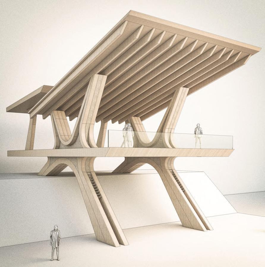
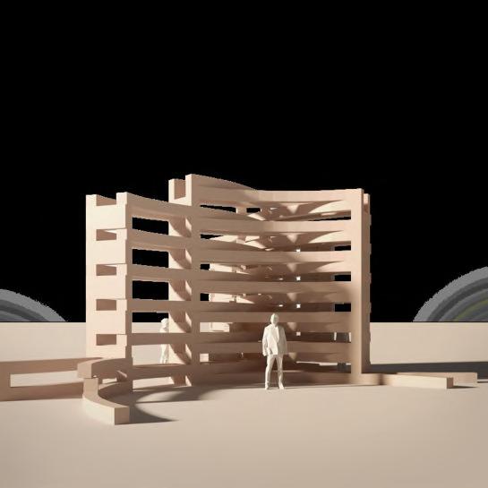
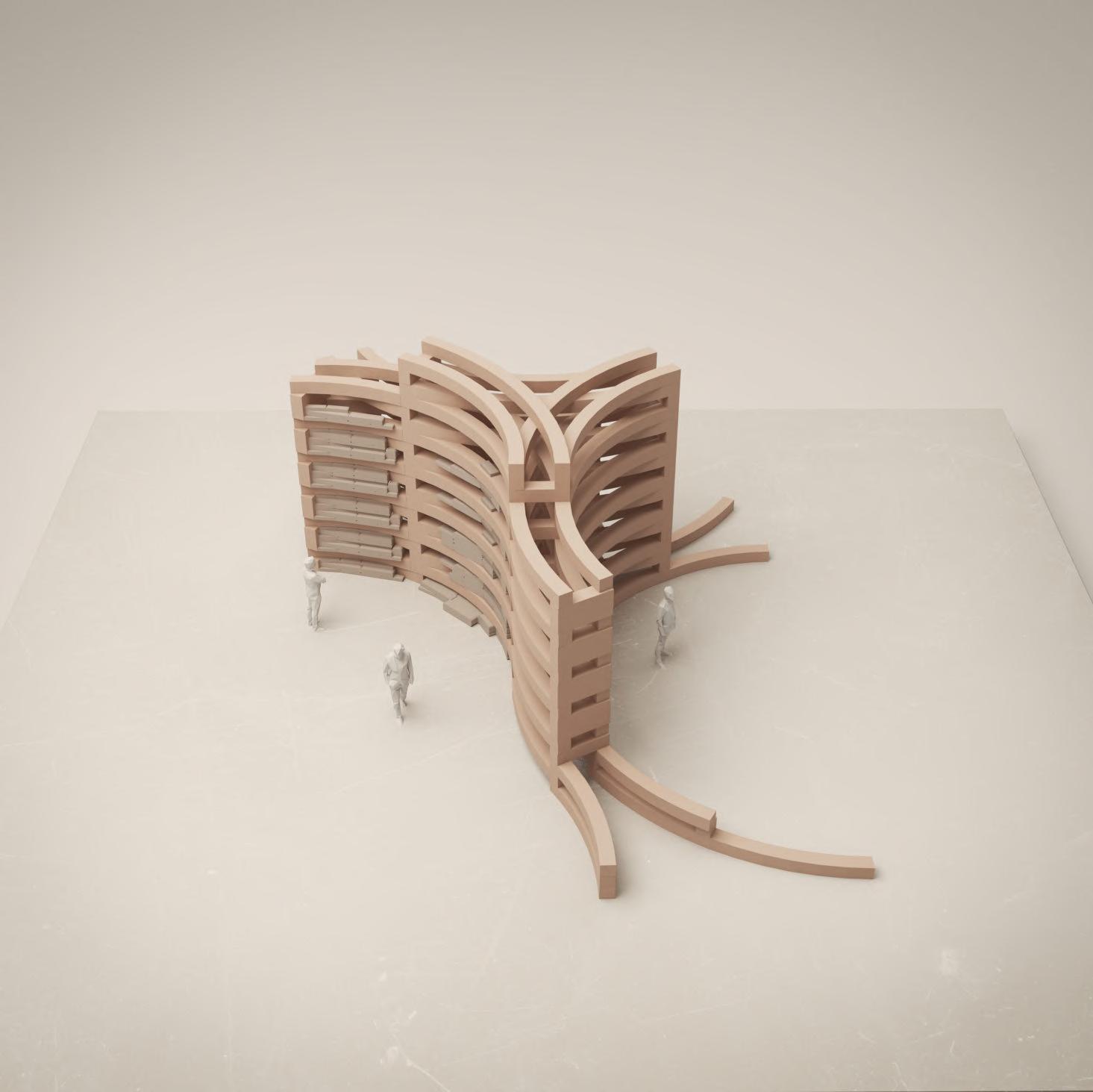
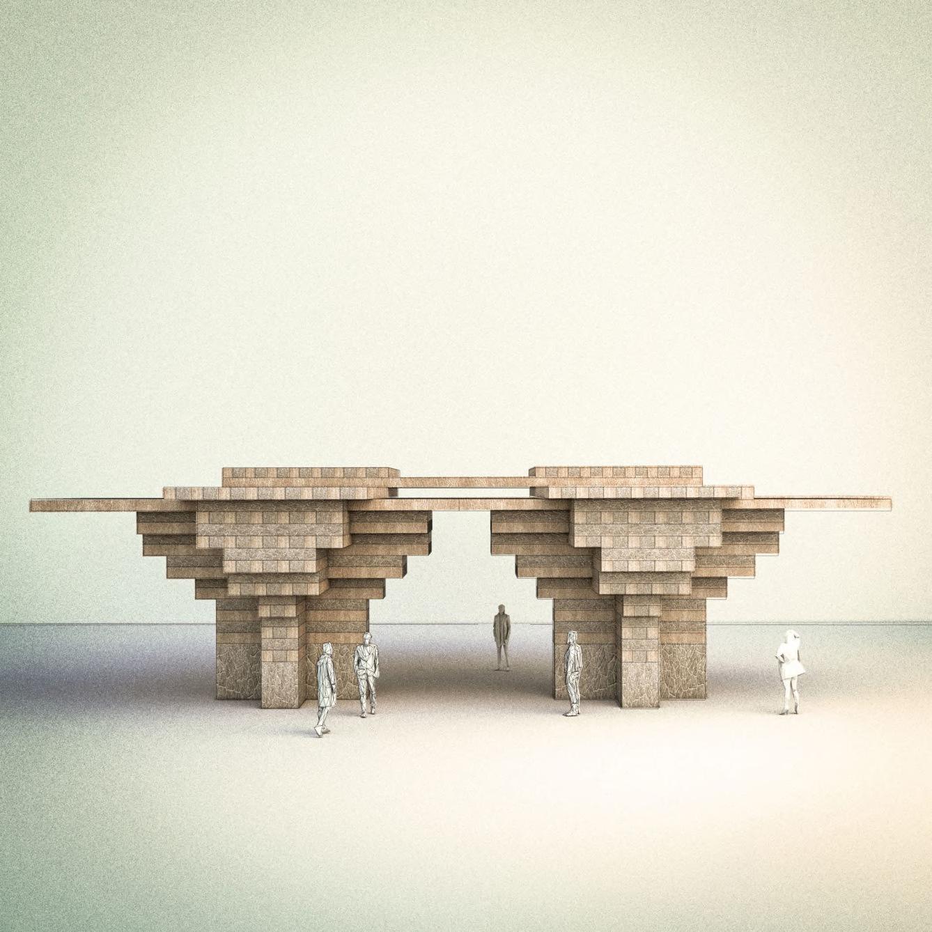
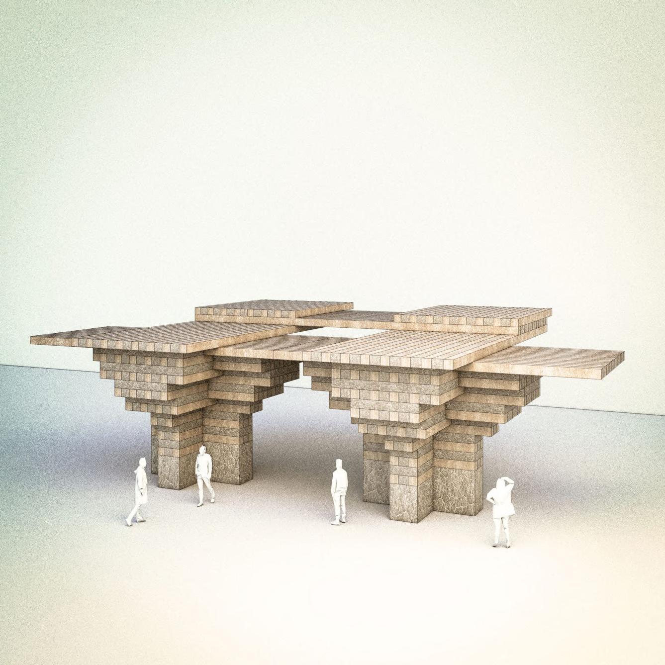
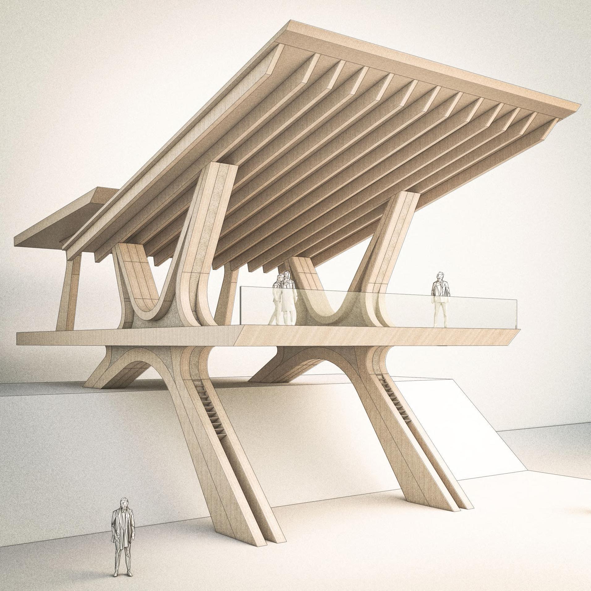
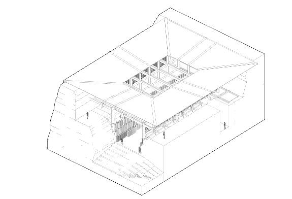
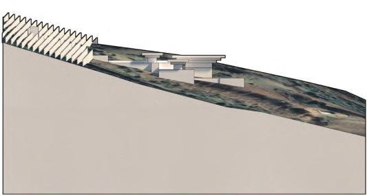
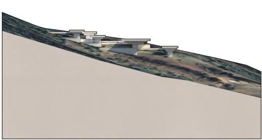
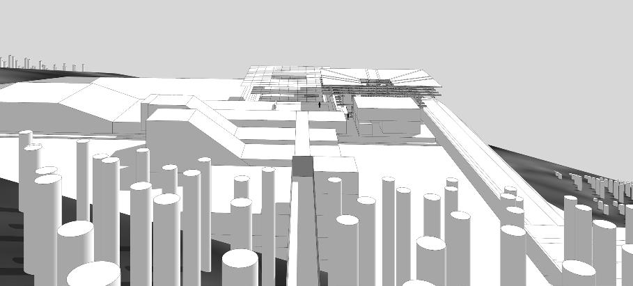
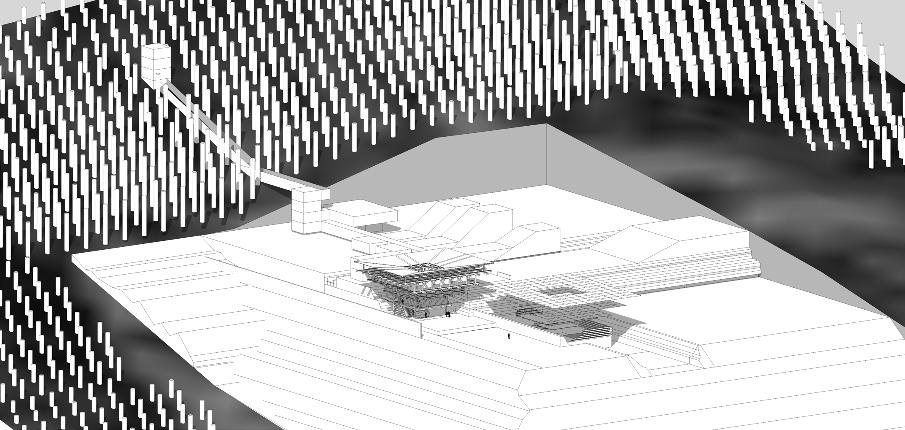
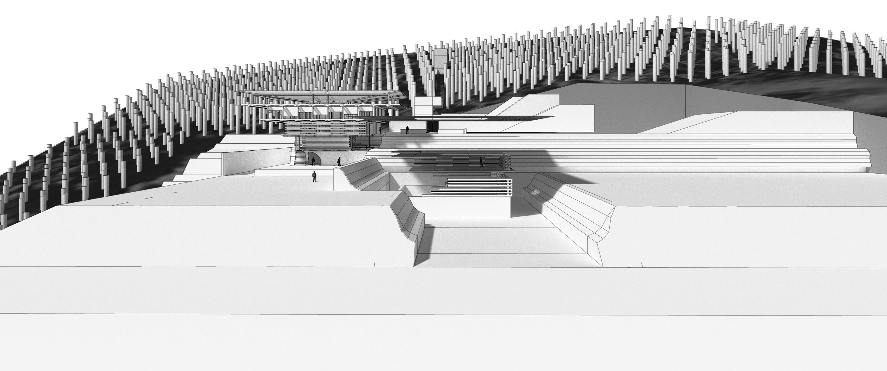
Iteration: CARPENTRY WORKSHOP
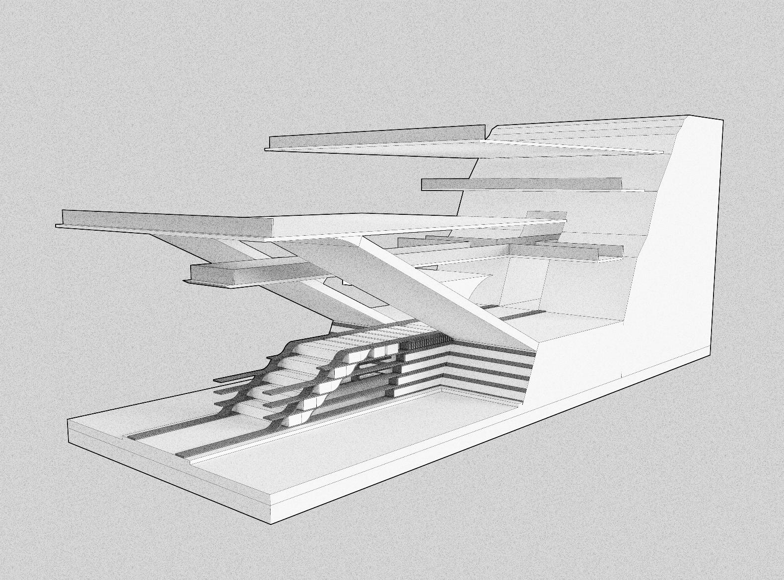
The carpentry workshop behaved as a key space to explore the development of structural and spatial strategies across the campus, as the design developed from low resolution massing studies to a higher resolution with increased detail.
03 Chapter 56 BARC0174 _ AAD1LHUENTSE SCHOOL OF CRAFTS
DESIGN DEVELOPMENT
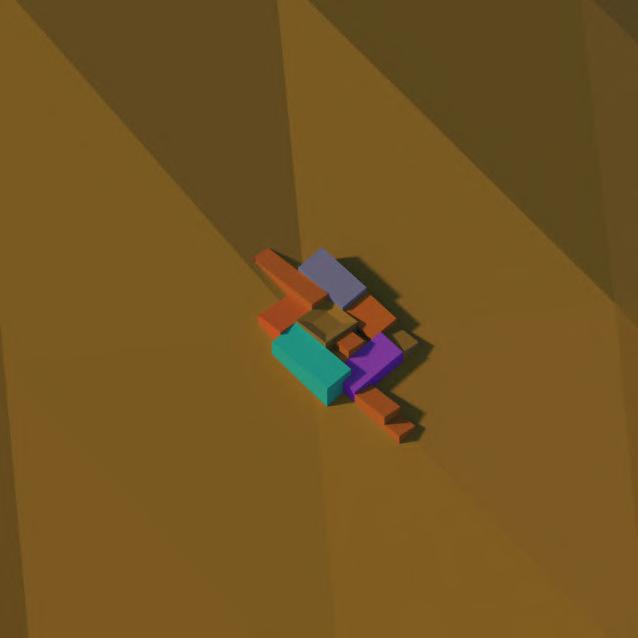
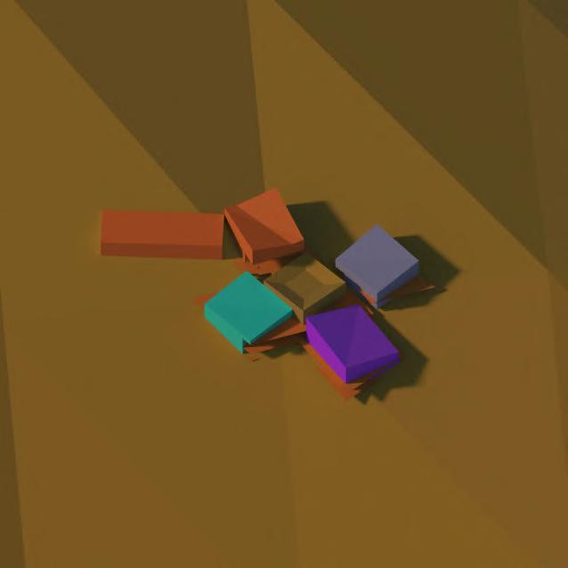
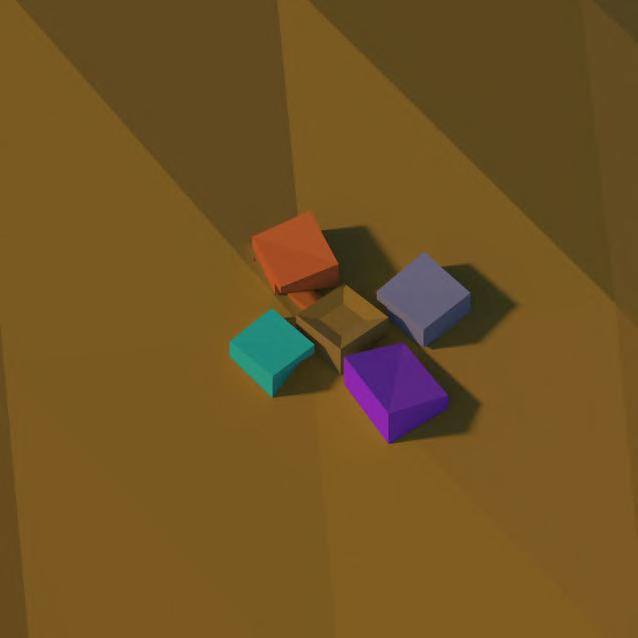
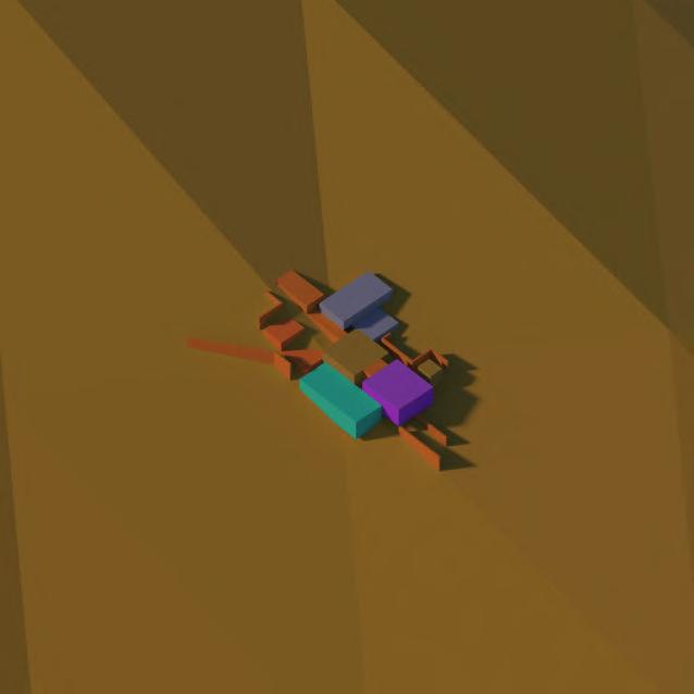
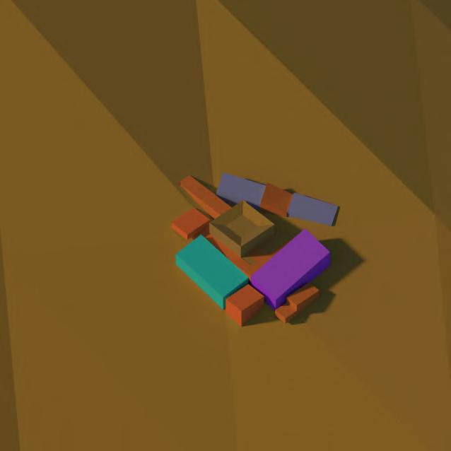
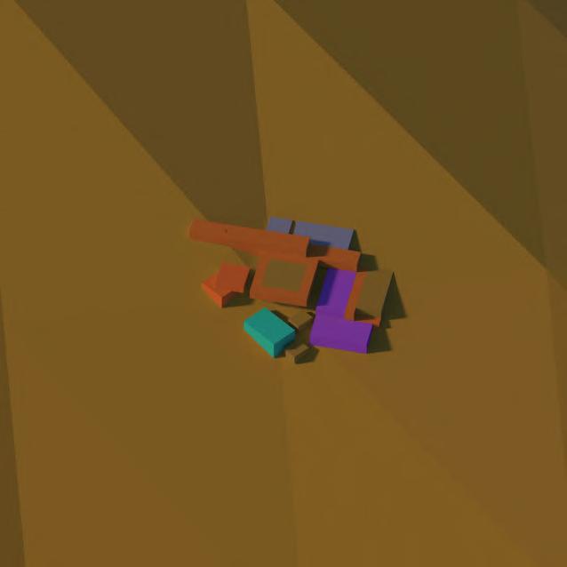
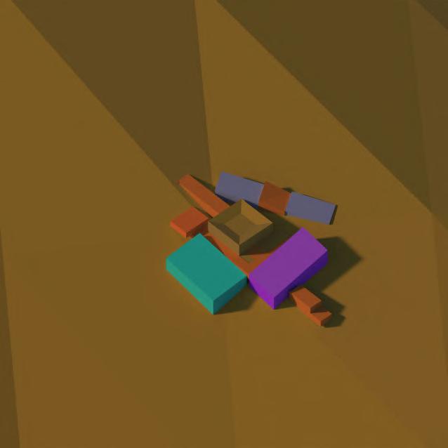
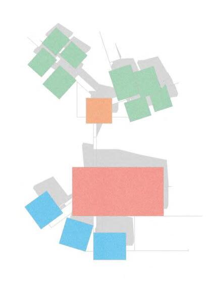
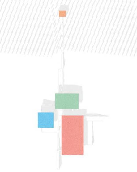
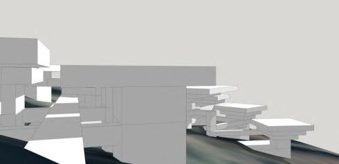
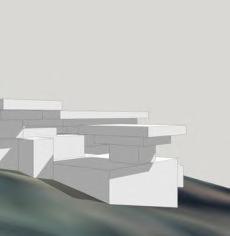
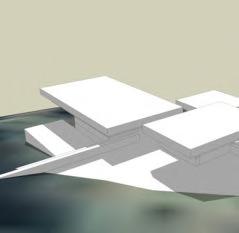
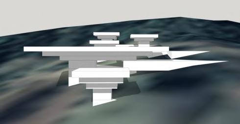
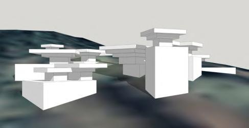
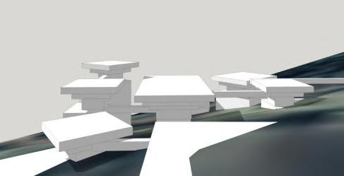
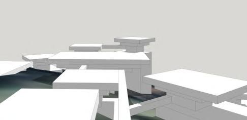
Global Form Development 01
Linear arrangement with cascading levels.
Linear plan with main volumes surrounding central courtyard, with dining volume reoriented to create expansive views.
Dining space reoriented parallel to central circulation spine.
Main volumes contained in square space on perimeter of central courtyard with staggered exit extending from central spine.
As Option 4, except sleeping volume rotated 90 degrees to create staggered transition to dining space.
All volumes (excluding entrance) concentrated to square plan with circulation on perimeter of central courtyard, transitioning between submerged and above ground interstitial circulation.
As Option 6, except main volumes overhang at edges to create shaded reflection spaces below.
Secondary courtyard introduced between sleeping and dining volume, with diagonal staggering from top right to bottom left of image.
1OPTION 5
OPTION
OPTION 3OPTION 7 OPTION 2OPTION 6 OPTION 4OPTION 8
15 3 7 26 48
3.01 _ Initial Zoning Studies
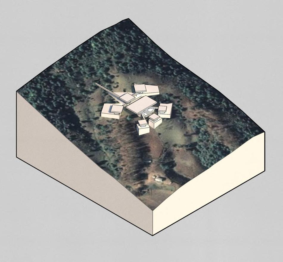
Fanning arrangement with courtyard spaces at corners and next to central courtyard.
Angled roofs with fanning arrangement, and scale of campus enlarged.
OPTION 10OPTION 14
Fanning arrangement with each volume rotated except for craft volume which remains parallel to original central axis. Introduction of staggered, rotated entrance lobby.
As Option 13, except staggered exit rotated and courtyard space introduced at corner of dining space and crafts volume.
OPTION 11OPTION 15
Linear arrangement with walls introduced to create enclosures and demarcate guided circulation routes.
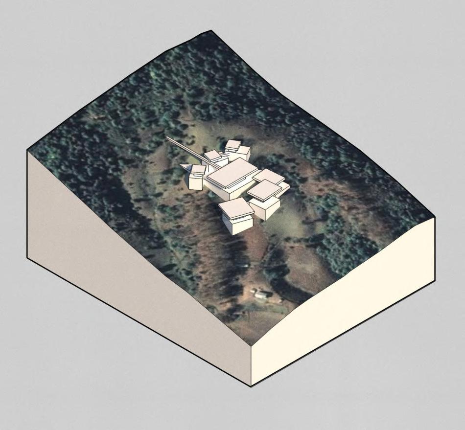
Each volume arranged in cluster on perimeter of central courtyard at slight angle with double planar roofs, to create hidden interstitial spaces on approach.
OPTION 12OPTION 16
Linear/square arrangement with roofs angled from top right to bottom left of image to maximise views.
As Option 15, except extended entrance volume introduced and three planes for paving on perimeter of each volume.

OPTION 9OPTION 13
9 13
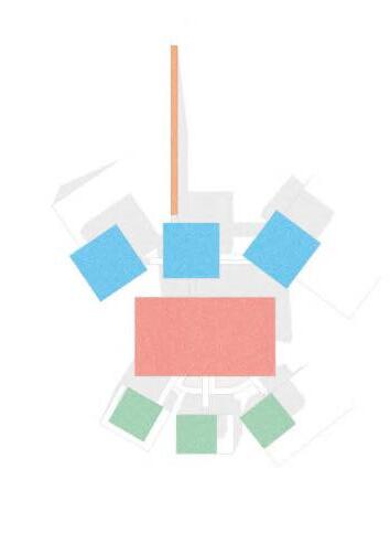
1216 KEY Multipurpose Auditorium & Dining Crafts & Education Meditation Spaces & Courtyards Interstitial Circulation Options of Interest Sleeping 58 BARC0174 _ AAD1CHAPTER 3 _ DESIGN DEVELOPMENT
1115 1014

LINEAR LINEAR CLUSTER AXIAL 01 02 03 Meditation space in forest Tall meditation space in forest Slender walkway intensifies scale of meditation volume Central walkway Overlapping roof planes Central meditation room Global Form Development 02 3.02 _ Initial Massing Studies
Multipurpose Auditorium & Dining
Sleeping
Crafts & Education
RADIAL 1
Meditation & Spiritual Provision
Courtyards
Options of Interest
Crafts in rear with restricted light, creating introspective workspaces
RADIAL 2
Sleeping in rear creating dappered light from forest
Meditation space in forest
RADIAL
Public Information/ Entrance Lobby
Interstitial courtyards

Sleeping provision faces north for naturally low lux lighting
Meditation space in forest
Radially expanding craft spaces

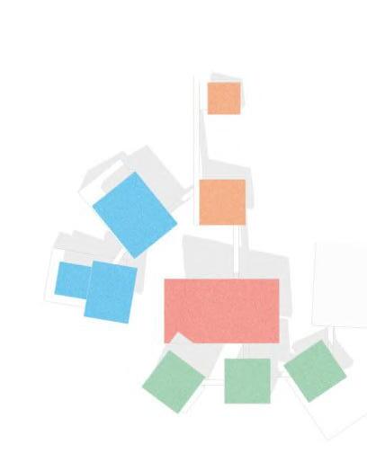
Meditation space in forest
Volume height increases clockwise, drawing attention to central space
KEY
60 BARC0174 _ AAD1CHAPTER 3 _ DESIGN DEVELOPMENT
3 04 05 06
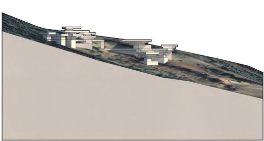
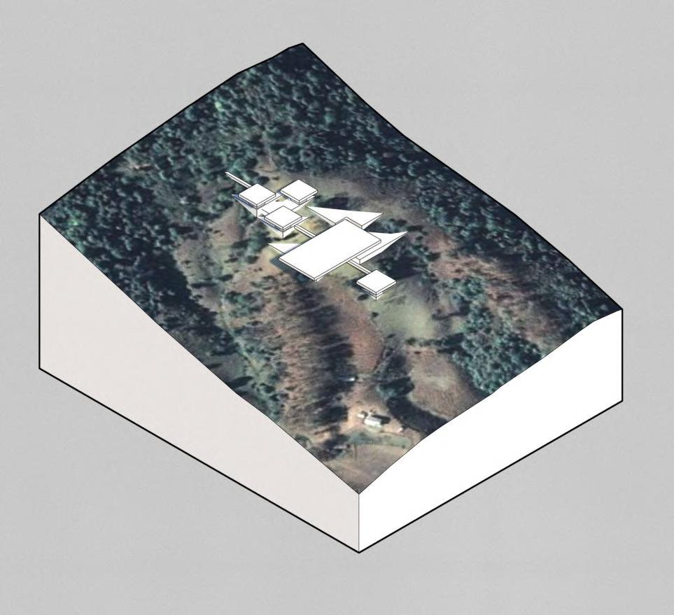
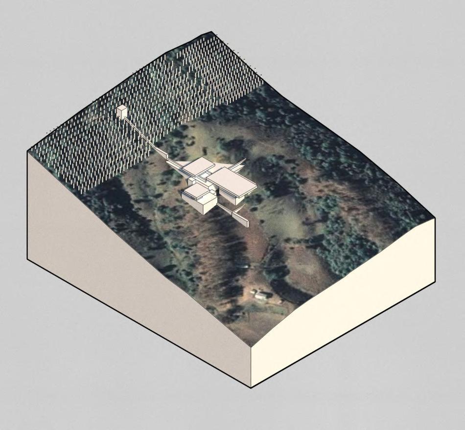
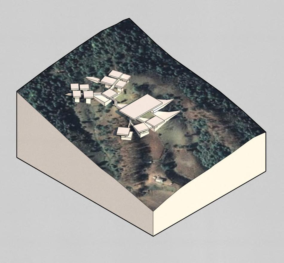
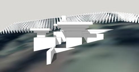
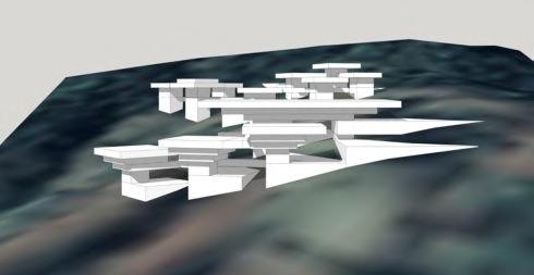
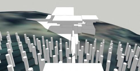
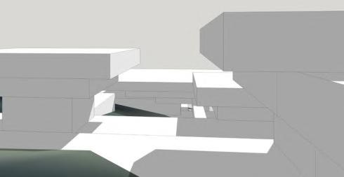
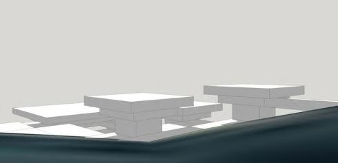
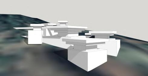
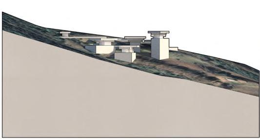
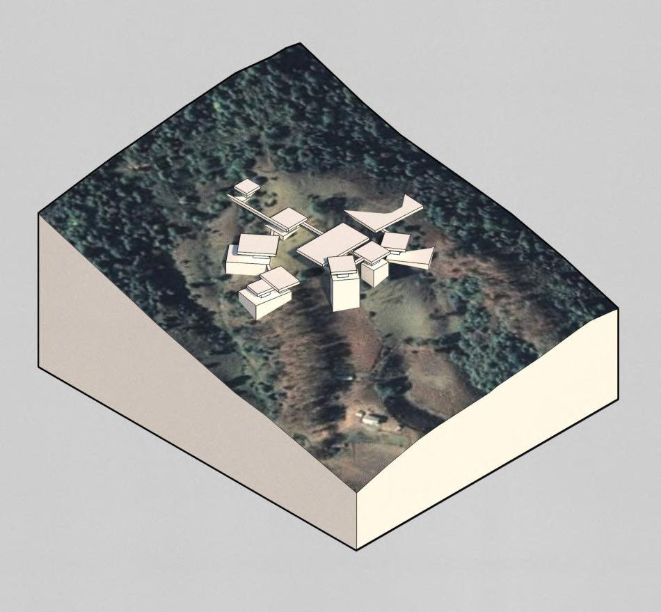
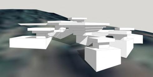
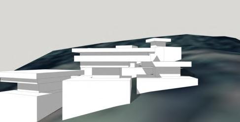
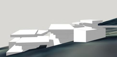
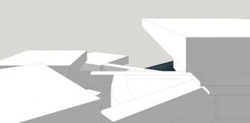
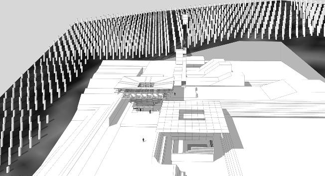
Design Iteration 01: Linear Cluster
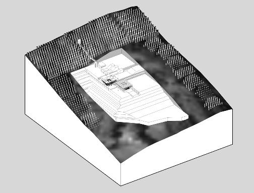
Rear landscape creates facility for extracting resources.
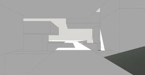
ROCK CARVING/WOODWORKING
ENTRANCE PERSPECTIVE 1 2 3 4 5 6 7 MEDITATION ROOM SLEEPING AUDITORIUM/ DINING CRAFTS
3.03 _ Developed Massing Study
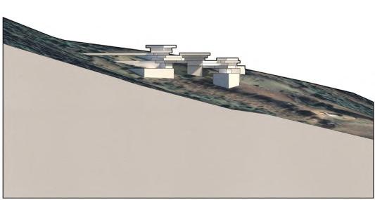
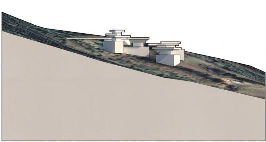
DESIGN ITERATION 01
Early global form development studies suggested that linear and linear cluster arrangements were most successful in achieving efficient circulation, and a visually clear form, alongside the introduction of a central courtyard. Design Iteration 01 (shown opposite) develops the linear cluster massing on the previous page at a higher resolution with storeys and carved/ above ground interstitial circulation. It also tests the
use of a tail which directs users to a meditation space within the nearby forest. Although useful as a test, it appears visually inconsistent with the campus’ orthogonal arrangement. Hence, further design development aims to take this into account, focusing instead on a tight, orthogonal cluster arrangement, to achieve visual consistency and circulatory efficiency.
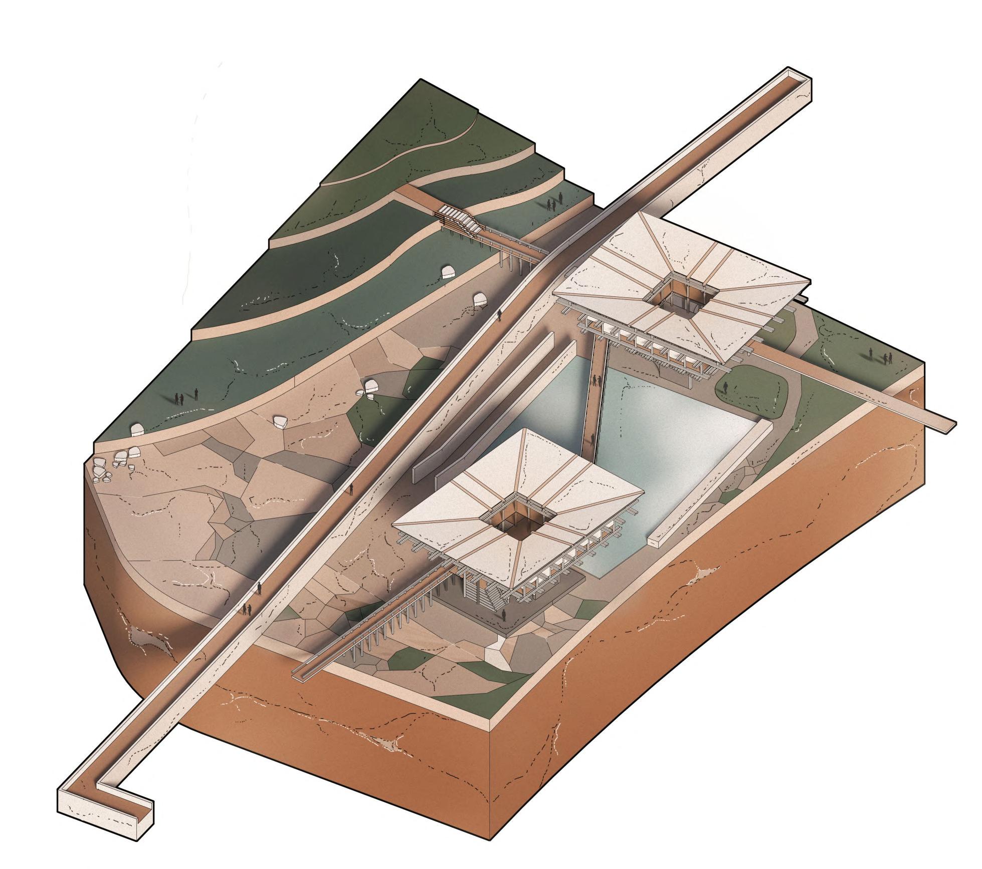
INTERSTITIAL CIRCULATION
As a further development of the spatial conditions explored in Design Iteration 01, the fragment below considers two volumes (similar to the ones conceived during the latter pages of ‘Initial Design Response’), in a non-linear arrangement. This intends to explore different above ground circulatory conditions, whilst framing the local terrain and harnessing the local climate.
Harnessing the Local Climate
Initial considerations towards a sustainable environmental strategy looked at the use of rainwater collection and harvesting, and sourcing produce from local vertical farms - a common feature of the Bhutanese landscape.
PRECEDENTS & TRANSFERABLE FEATURES
THE WALLED, TSINGPU YANGZHOU RETREAT, CHINA Neri & Hu
- Use of permeable walls
- Water features
- Non-invasive
- Prematurely old yet modern
- Reinventing ancient typology of walled gardens in China
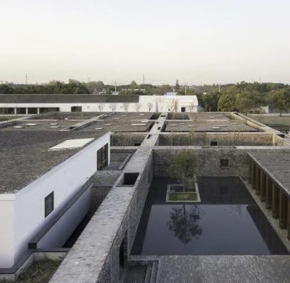
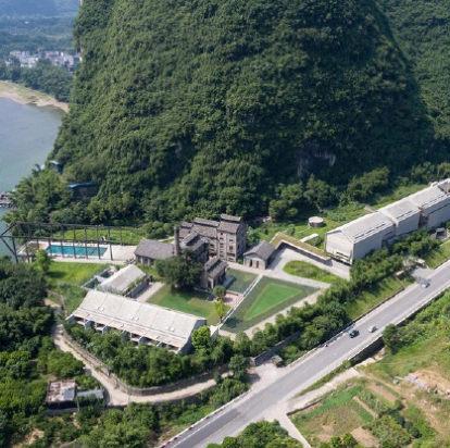
Precedents
The overall form aims to incorporate east Asian, Chinese modernist influences with the historic Himalayan precedents initially explored to consolidate a hybrid, non-exclusive identity for hybrid user groups across the Himalayas and Asia, as well as abroad.
ALILA YANGSHUO HOTEL, CHINA
Vector Architects
- Mountainous backdrop, flat terrain, close to sea
- Retrofit of industrial mill - prematurely old, yet modern
- Proximity to roads, but still remote
- Typology: Reworked leisure, cluster arrangement
AGRICULTURE & FARMING PERMEABLE ENCLOSURE EDUCATION ELEVATED WALKWAY WATER COLLECTION INCLINED TERRAIN 01 02 04 06 05 03
62 BARC0174 _ AAD1CHAPTER 3 _ DESIGN DEVELOPMENT
Figure 3.03AFigure 3.03B
Design Iteration 02: Volumetric Study
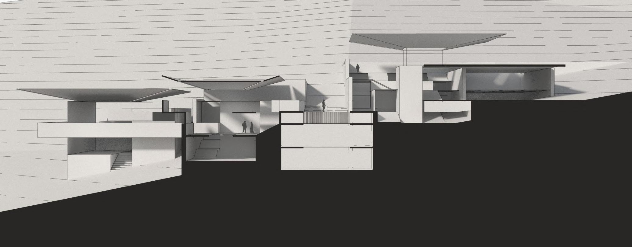
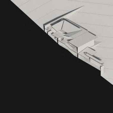
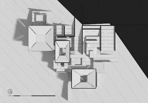
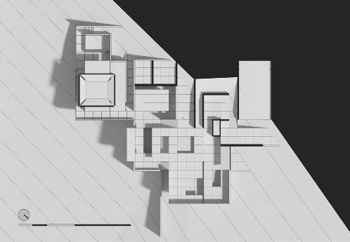
COMPACT CLUSTER ARRANGEMENT
As an adapted response to Design Iteration 01, Iteration 02 develops a cluster of several volumes outside of a central courtyard, each employing the characteristic inward facing roof form. The tail from Iteration 01 has been removed, with spaces for self-reflection sitting beneath workshop, dining and eating spaces. This arrangement in plan intends to create more efficient circulation with each major space sitting adjacent to the central courtyard, with woven paths sitting across separate planes to create surprise during circulation. Each of the volumes are also offset from the central courtyard, creating differentiation in scale and height to create a visual hierarchy for onlookers on approach. However, this iteration suggests that an entrance that inclines upwards would be more appropriate for building users, and an increase in scale would be more suitable for the building’s campus typology.
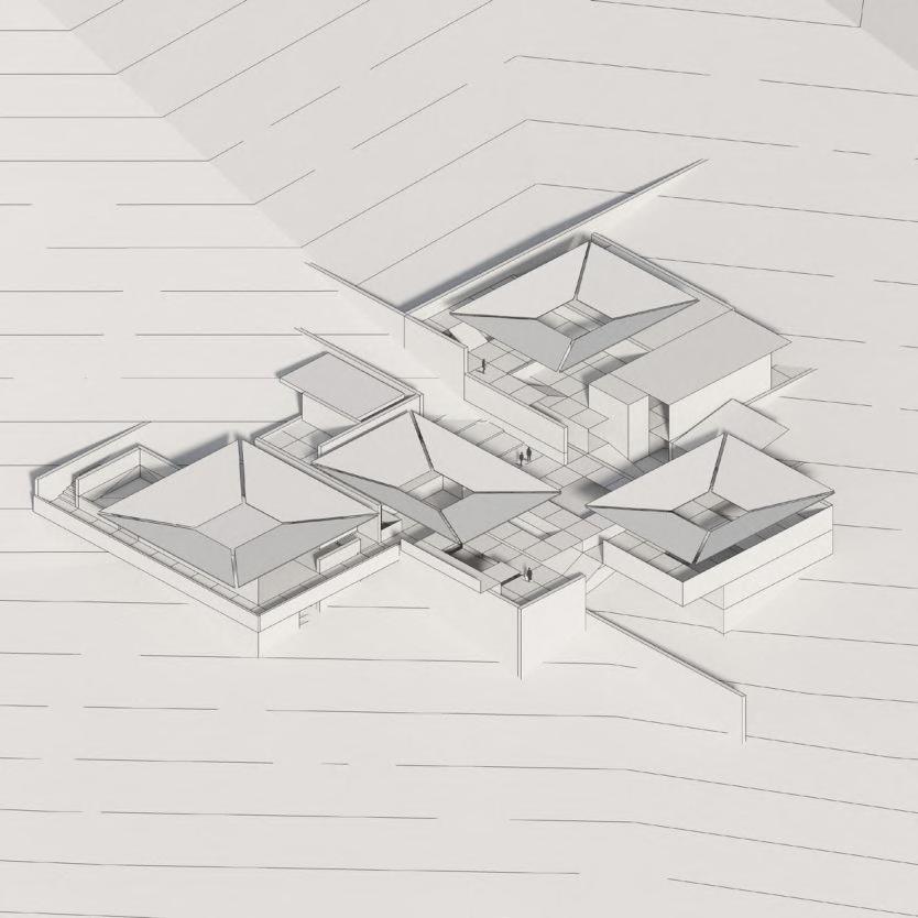
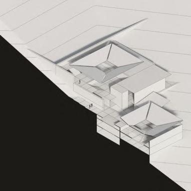
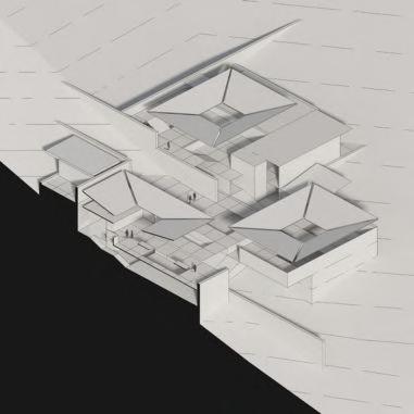
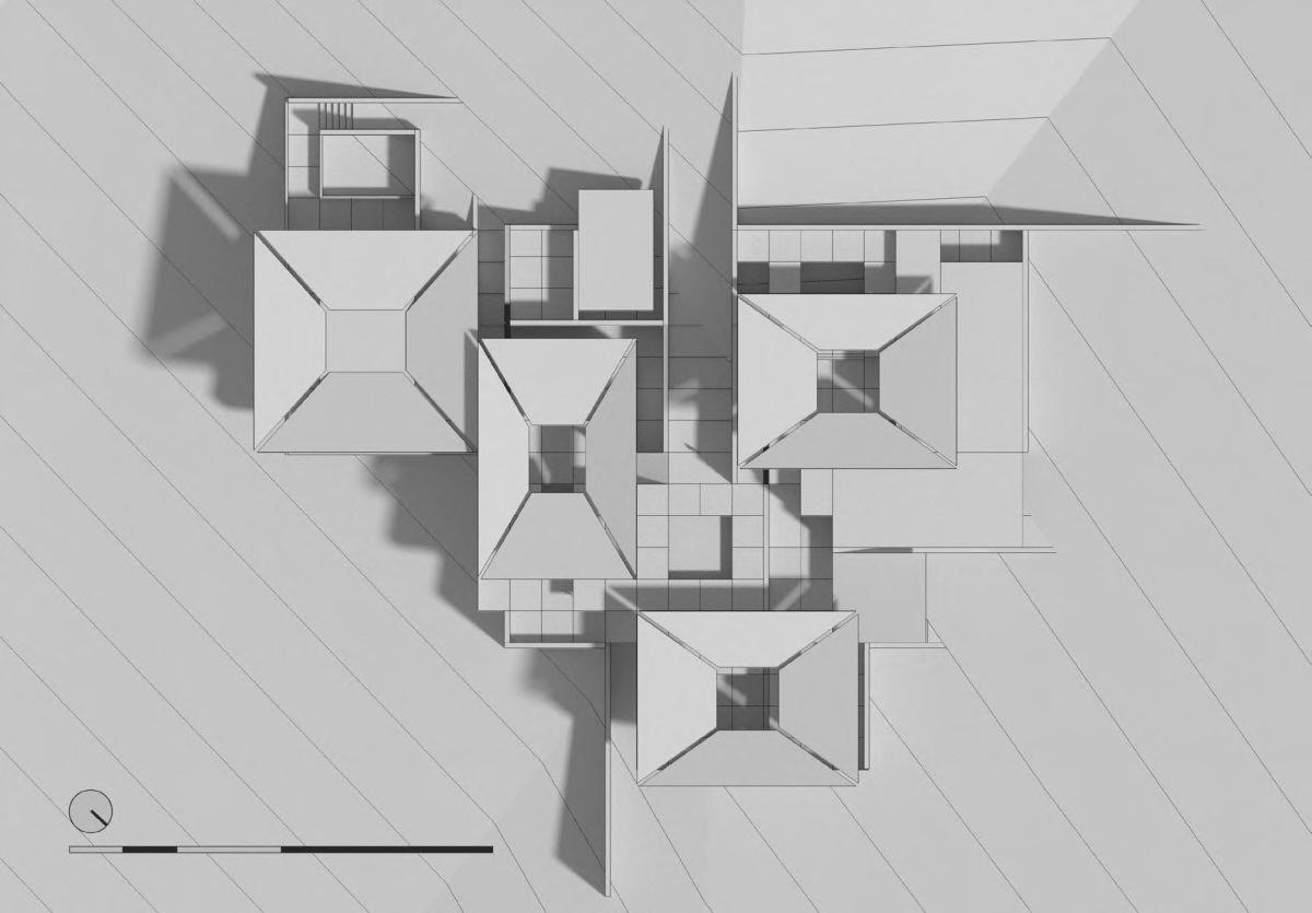
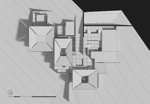
Level 01 AAAAAA Level 02 Level 03 0 0 55500010101020202040m40m40m Long Perspective Section AA Roof Plan ‘Crafts’ Section ‘Entrance to Dining’ Section ‘Sleeping’ Section Aerial Isometric View 50102040m
3.04 _ Plan Development ABC
DEVELOPING ROOF FORM
Using the global form in Design Iteration 02 as a basis to further explore the campus’ roof, the below diagrammatic studies consider alternative roof forms that could be standardised across the campus. Each of the studies progress in scale, beginning with a cantilevered inward looking roof form, aiming to maximise floor area on upper levels, whilst retaining a smaller footprint on the ground floor. This allows an opportunity for the interplay of planes
on upper storeys, creating unconventional passages and walkways for building users. While the studies suggest that the inward facing roof pitch is most suitable for the campus due to ease of construction, its orthogonal form and its opportunity to harness light and the local climate, a fragment study of the carpentry workshop on pages 69-70 also considers the possibilities of a monopitch roof form.
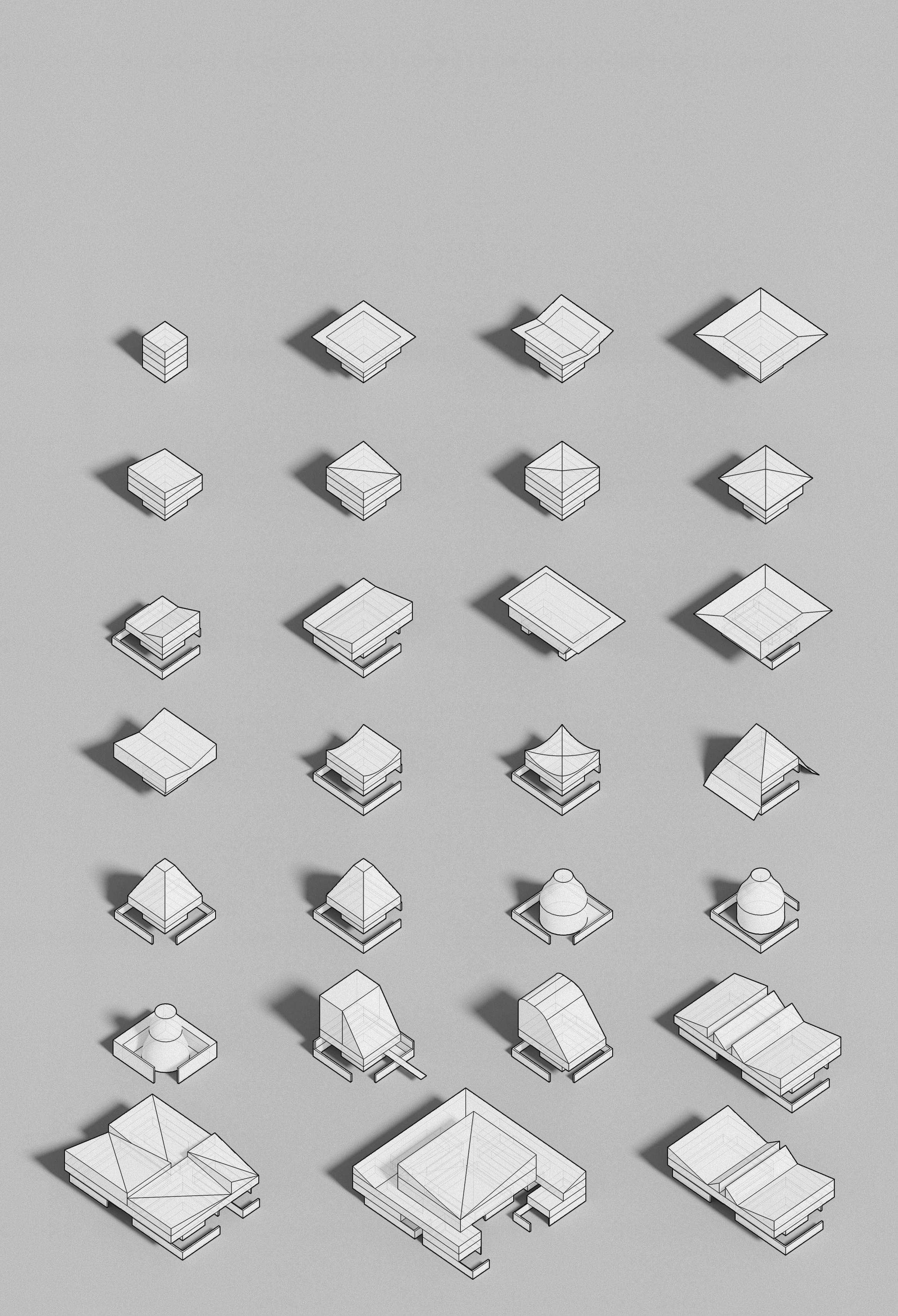 Please see pages 69-70 for Carpentry Workshop fragment testing monopitch roof form
64 BARC0174 _ AAD1CHAPTER 3 _ DESIGN DEVELOPMENT
Design Drivers
ZONING
Programme on perimeter of central courtyard
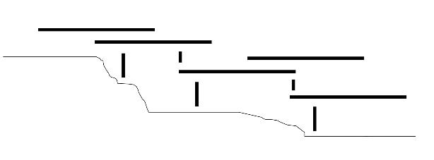
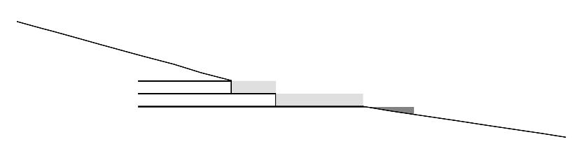
A main central courtyard sits adjacent to the workshop, sleeping and dining spaces allowing an exchange of activity between the volumes. Highlighted in black are smaller scale courtyard spaces that are generated when the volumes intersect and are offset.
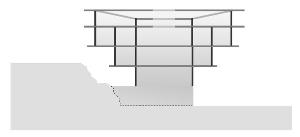
COURTYARDS
Shifting main volumes to create courtyard spaces
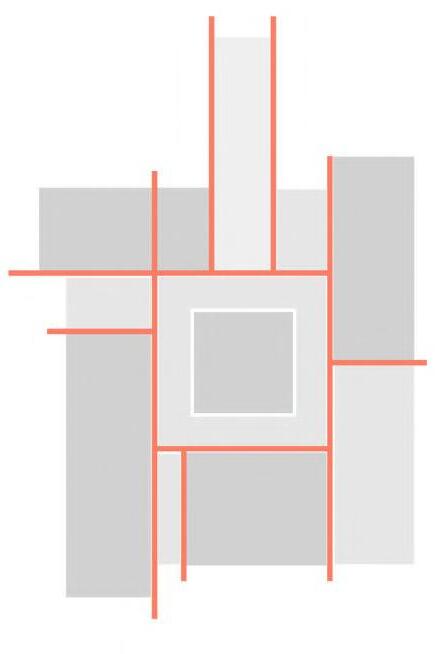

Shifting each of the main volumes inside of which the campus’ main programme exists, creates several outdoor and indoor courtyards on the ground floor for use by students and teachers.
CIRCULATION
Negative Space creates opportunity for interstitial circulation

The condition outside of the main volumes is occupied predominantly by circulation space, alongside provision for exhibitions, teaching and study.
CASCADING GROUND
Staggered roofs create clear horizontal datums in elevation whilst redirecting rainwater across campus.
INTERSTITIAL SPACE
Weaving submerged and above ground circulation
The introduction of upper storeys provides the opportunity to weave circulation between separate planes, allowing a new network of walkways and passages to develop. This creates elements of surprise while encouraging users to learn about different spaces across the campus.
INTERSECTING PLANES
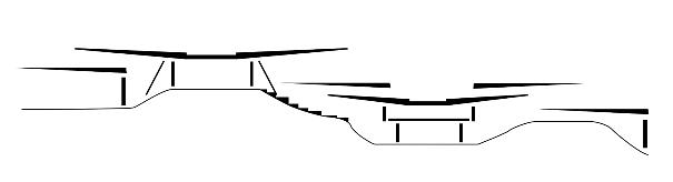
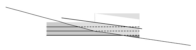
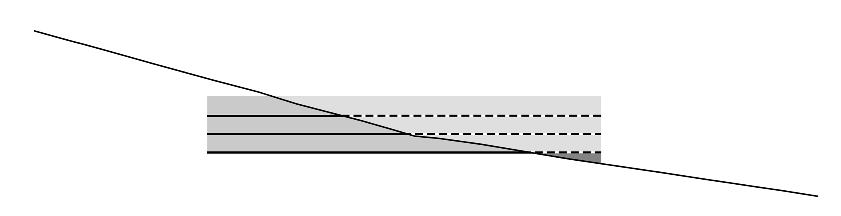
INTEGRATED LANDSCAPE
A hybrid timber stone plinth merges with the landscape to enhance the visual hierarchy of the superstructure.
INTEGRATED PLINTH TIMBER SUPERSTRUCTURE
The dry stone timber plinth is integrated into the rocky landscape with a skeletal timber superstructure sitting above. A cantilever also creates an overhang for reflection spaces below.
Stone plinth
Section 3.05 Storeys Cut FillCascading Steps 01
02 03
INTERSTITIAL SPATIAL CONDITIONS


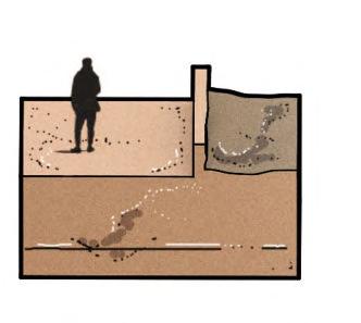
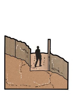
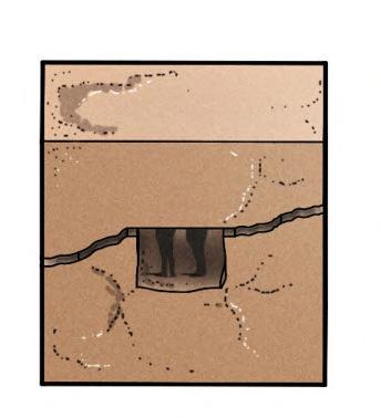
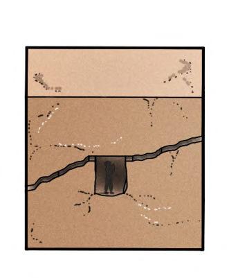
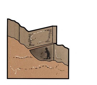
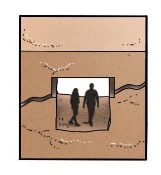
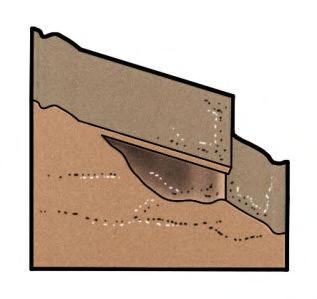
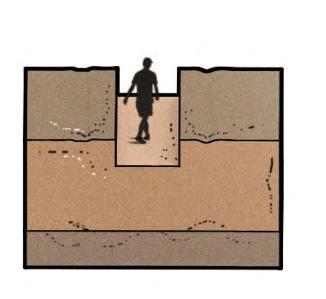
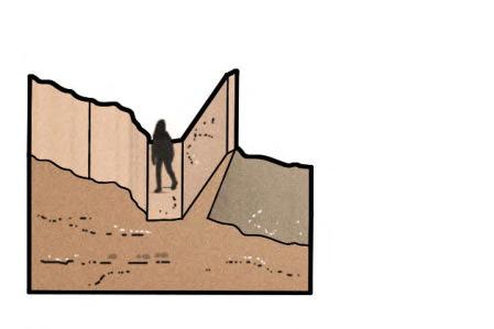
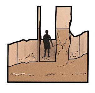
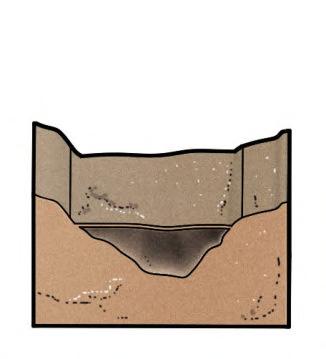
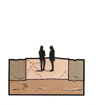
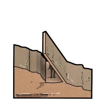
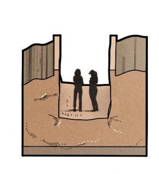
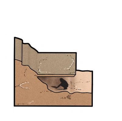

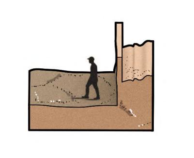
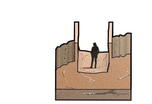
The matrix displays several conditions that may contribute to the overall experience of circulation across the campus. Each may be incorporated into either interior or exterior spaces.
VERTICAL
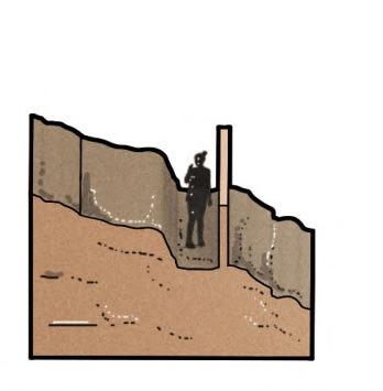
INSIDE TRENCH TRENCH SUBMERGE SUBMERGE SUBMERGE OUTSIDE ANGLED VALLEY COMPRESS EXPAND FLAT ABOVE PLANE SUNKEN BELOW HIDDEN CANOPY VERANDA
HORIZONTAL
66 BARC0174 _ AAD1CHAPTER 3 _ DESIGN DEVELOPMENT Figure 3.05A
Volumetric Studies: Carved Earth
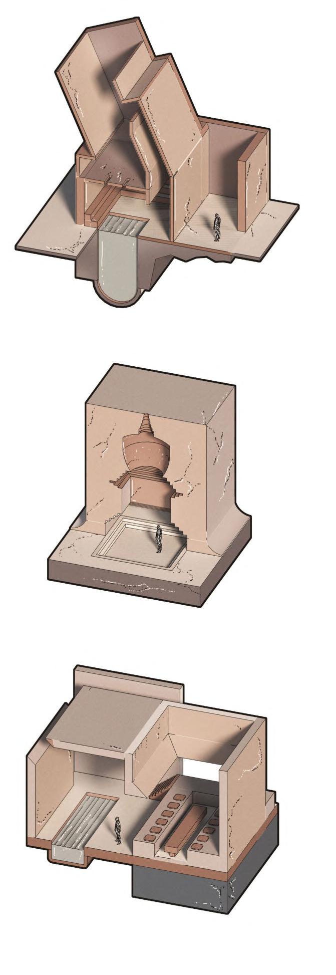
ABSTRACTING LOCAL BHUTANESE ARCHITECTURE
Using the compact nature of Bhutanese dwellings as reference, the above studies combine the campus’ programme with planes across different axes to mimic different aspects of Bhutanese architecture. By abstracting conditions such as passages, chortens, gardens, dining and forests, the volumetric studies manipulate light to create spaces for reflection, study and activity. They each behave as a precedent for the development of bespoke internal environments that may be achieved across the campus.
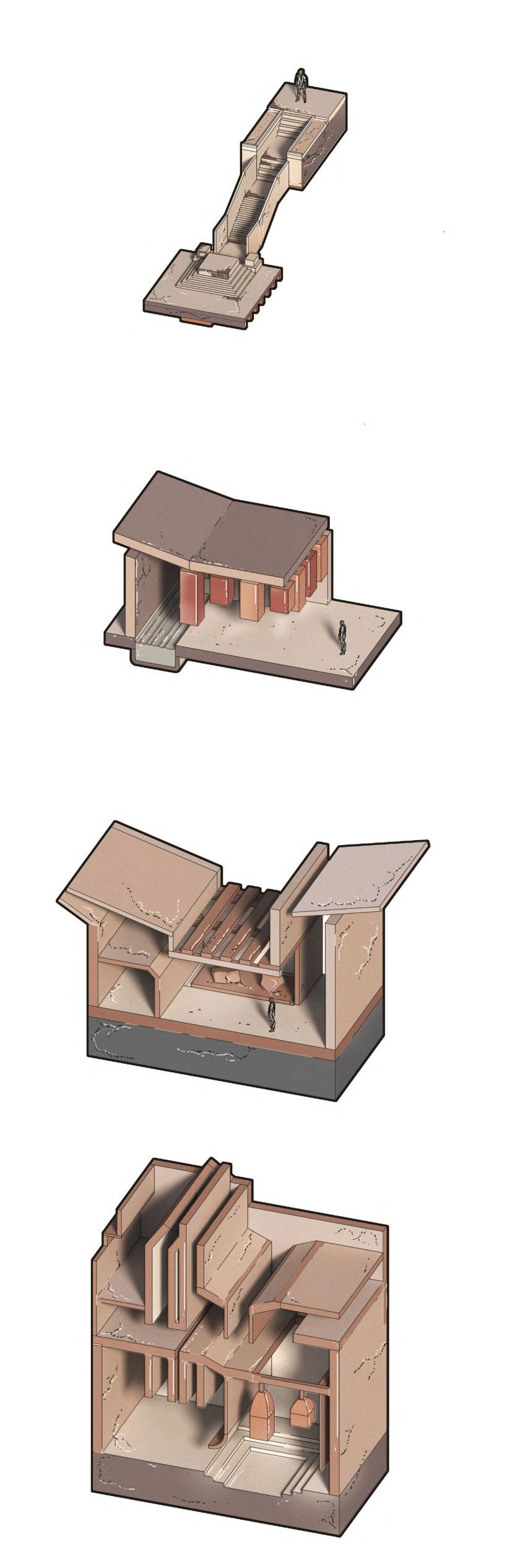
3.06 _ Design Concept 01 67 Figure 3.06A
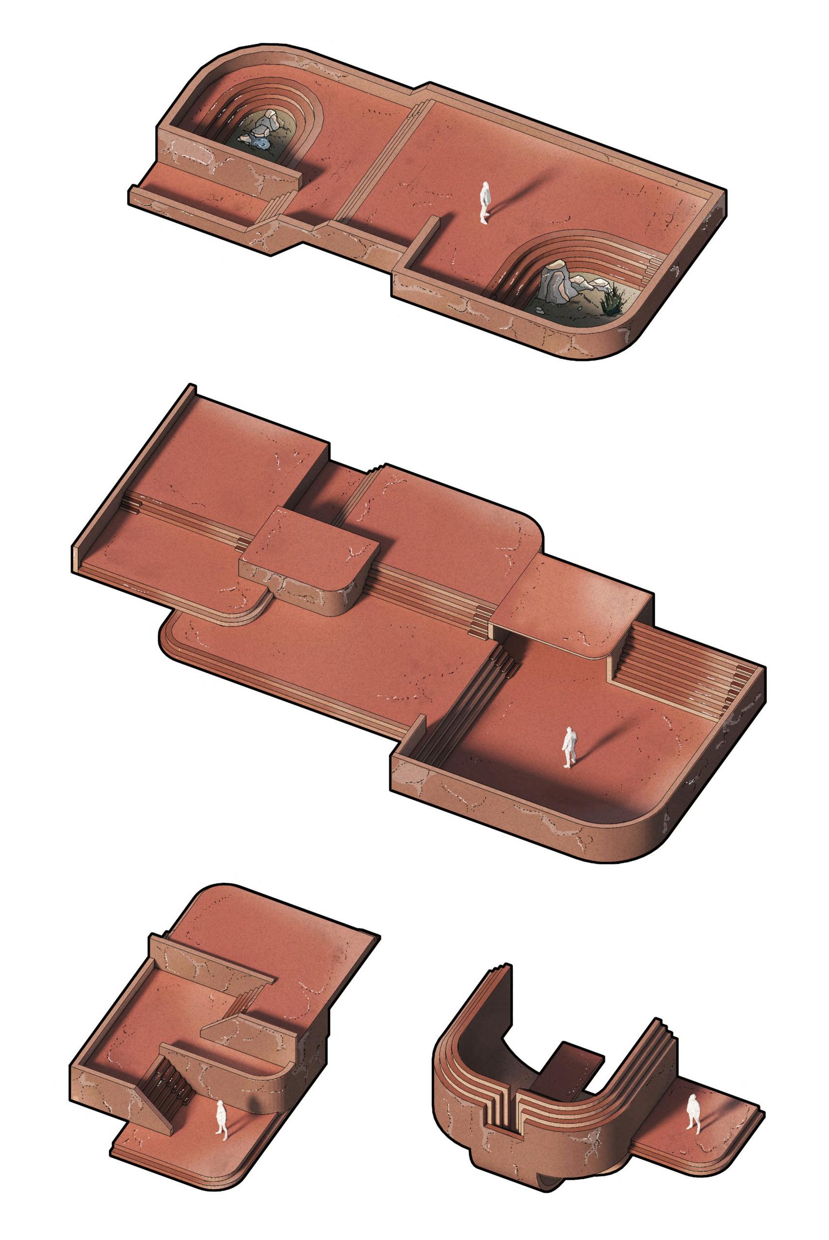
3.07 _ Design Concept 02 68 Figure 3.07A
Landscape Integration: Cascading Ground
Carpentry Workshop Fragment
CONSOLIDATED DESIGN RESPONSE
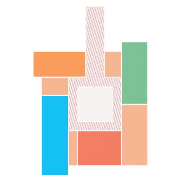
As a development of the earlier massing studies, the key design concepts and the monopitched roof form considered earlier, the carpentry workshop fragment shown right consolidates each of these features while exploring the application and adaptation of Kath Khuni at a higher design resolution.
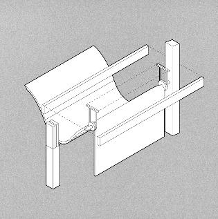
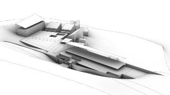
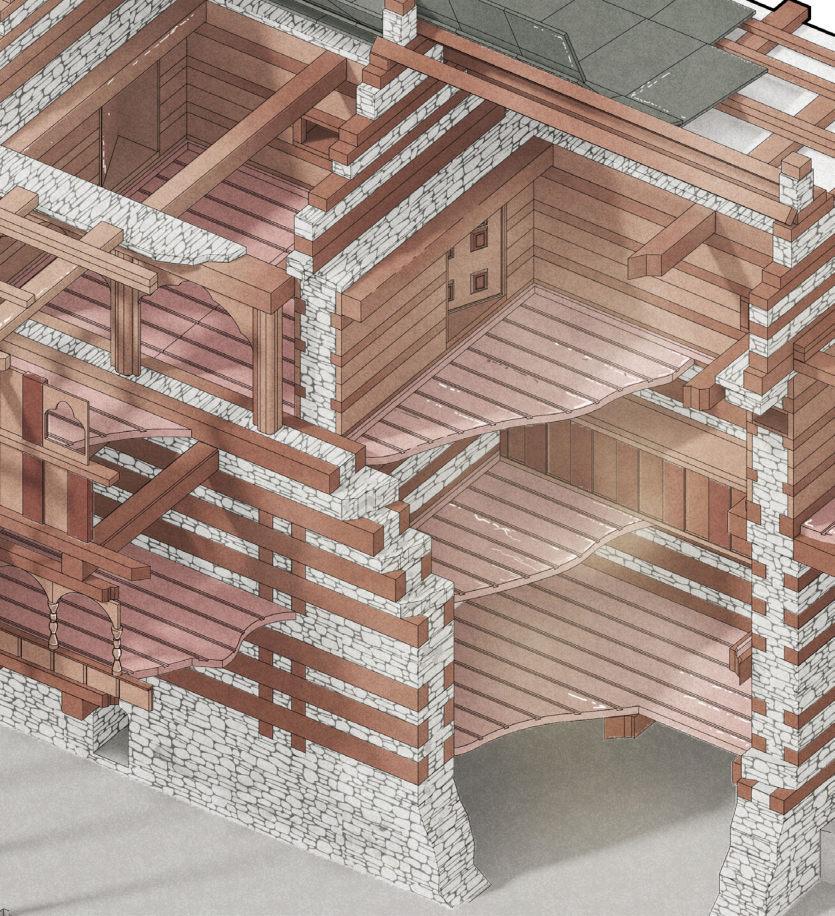
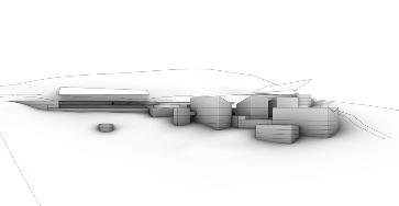
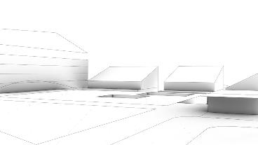
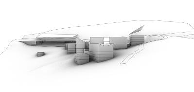
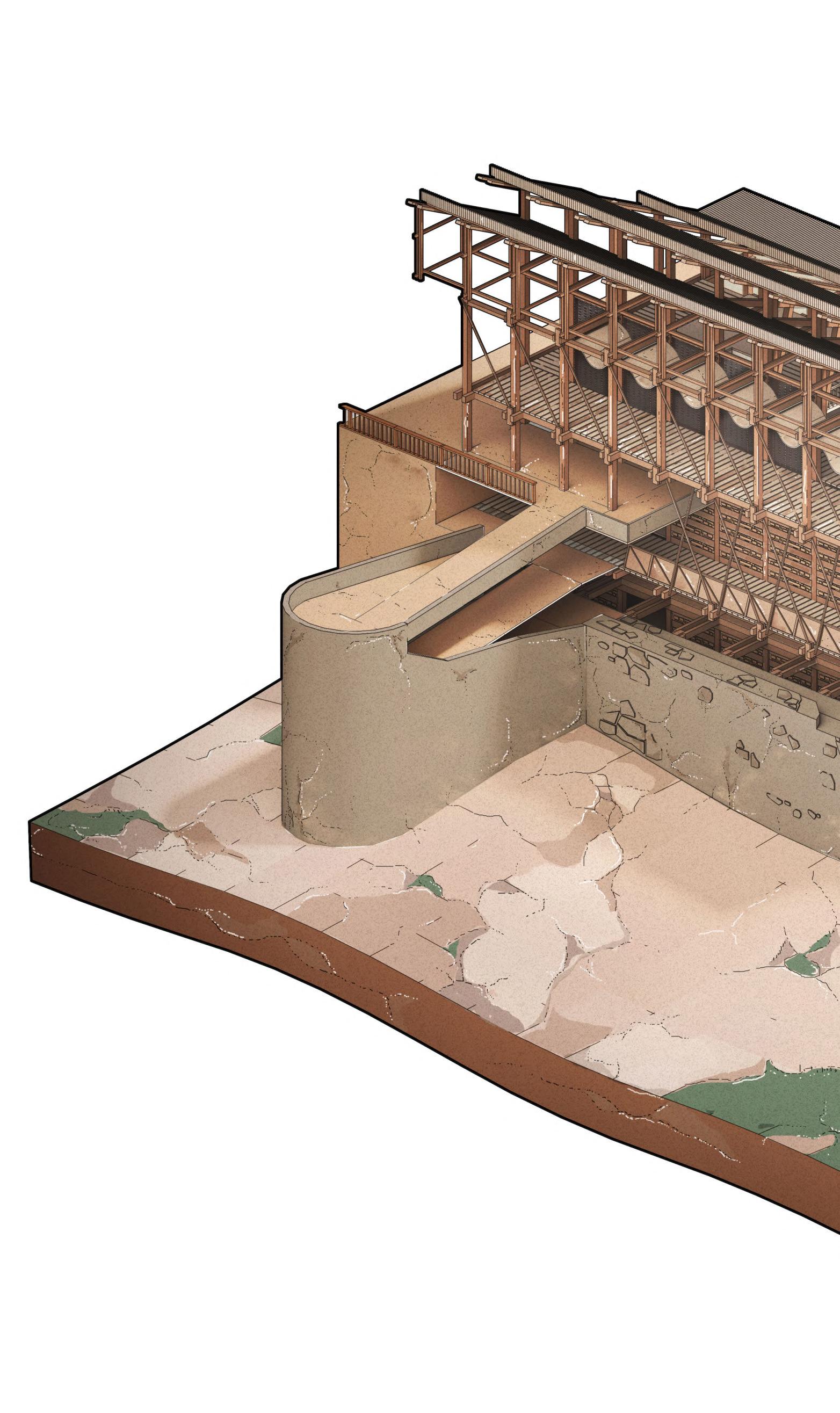
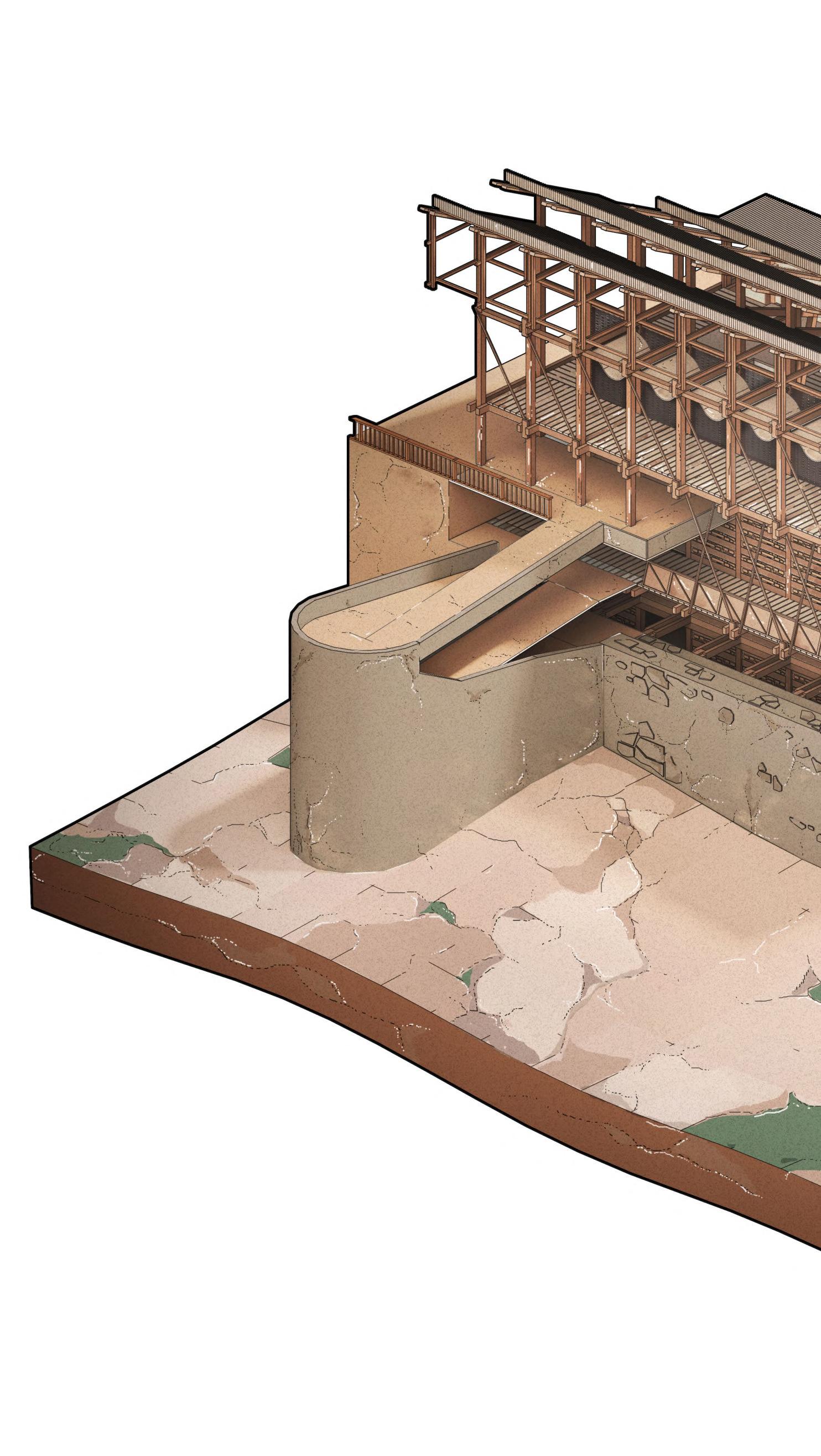
LOW TECH METHODOLOGY
Using a combination of locally available wood and dry stone, the construction process aims to be sustainable by preventing excessive material use and encouraging local labour.
EARLY MASSING ITERATION
STRUCTURAL STRATEGY: KATH KHUNI CONSTRUCTION KEY POIN
The fragment adapts Aukta House’s characteristic construction technique of layered bands of wood and stone topped off by slate roofs. Its use across large darbargadhs and intricate temples, to smaller dwellings is distinctive in silhouette.
Kath Khuni plinths are constructed entirely of stone. Layers of stone and woods are then constructed with a double skin and its internal cavity is filled with rubble. External and internal skins are held together by cross-braces.
The heavy stone base carries the lighter wooden structure at upper levels. No mortar is used between the courses and the shear weight of dry masonry holds it down in place.
ZONING Programme on perimeter of central courtyard
The central courtyard creates a flat plane into which a sunken library, classroom and meditation space are located. The large cantilevered and pitched hybrid volumes sit on the perimeter of the courtyard, adhering to an orthogonal general arrangement whilst concealing and revealing views.
PRIMARY STRUCTURE
Using a series of differ members that use the the members gradually at the upper levels to superstructure form. tertiary timber members interlock with stone to heating and cooling within space.
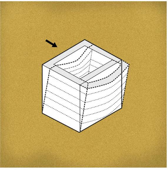
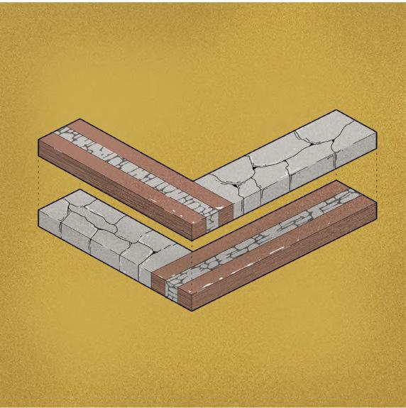
WALLLOADEDIN-PLANE
OUT-OF-PLANE LOADEDWALL
TS INTERLOCKING STONE/TIMBERSEISMIC
3.08 _ Consolidated
Response
Design
Figure 3.08A
STRUCTURE
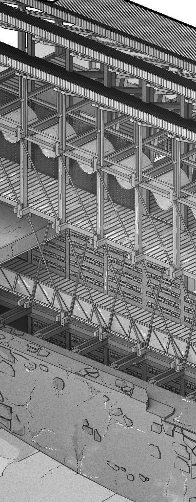
differentiated timber the plinth as support, adually reduce in size create the plinth Secondary and members angle and to provide alternating within the workshop
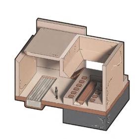
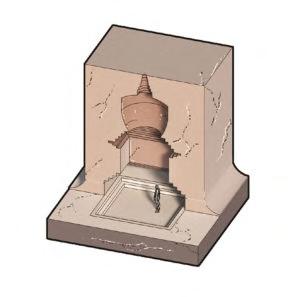
FACADE TREATMENT

KEY PRECEDENT: AUKTA HOUSE, OLD JUBBAL
HEMP FABRIC Reduces solar gain & provides shade
WOVEN INTERNAL FABRIC
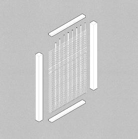
CASCADING CIRCULATION / CARVED GROUND
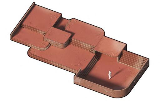
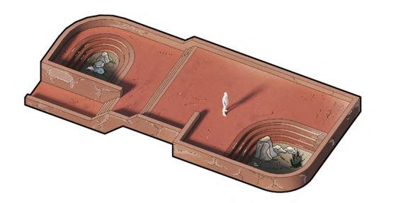
EARLY SITE PLAN: CARPENTRY WORKSHOP LOCATION
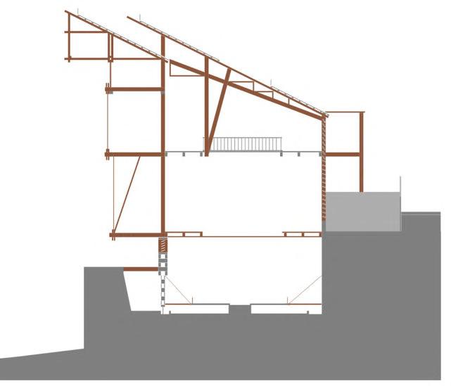
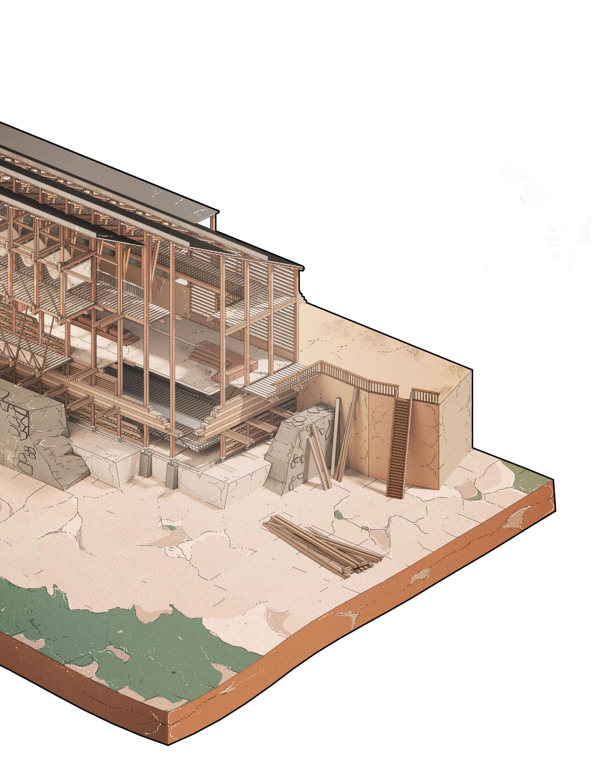
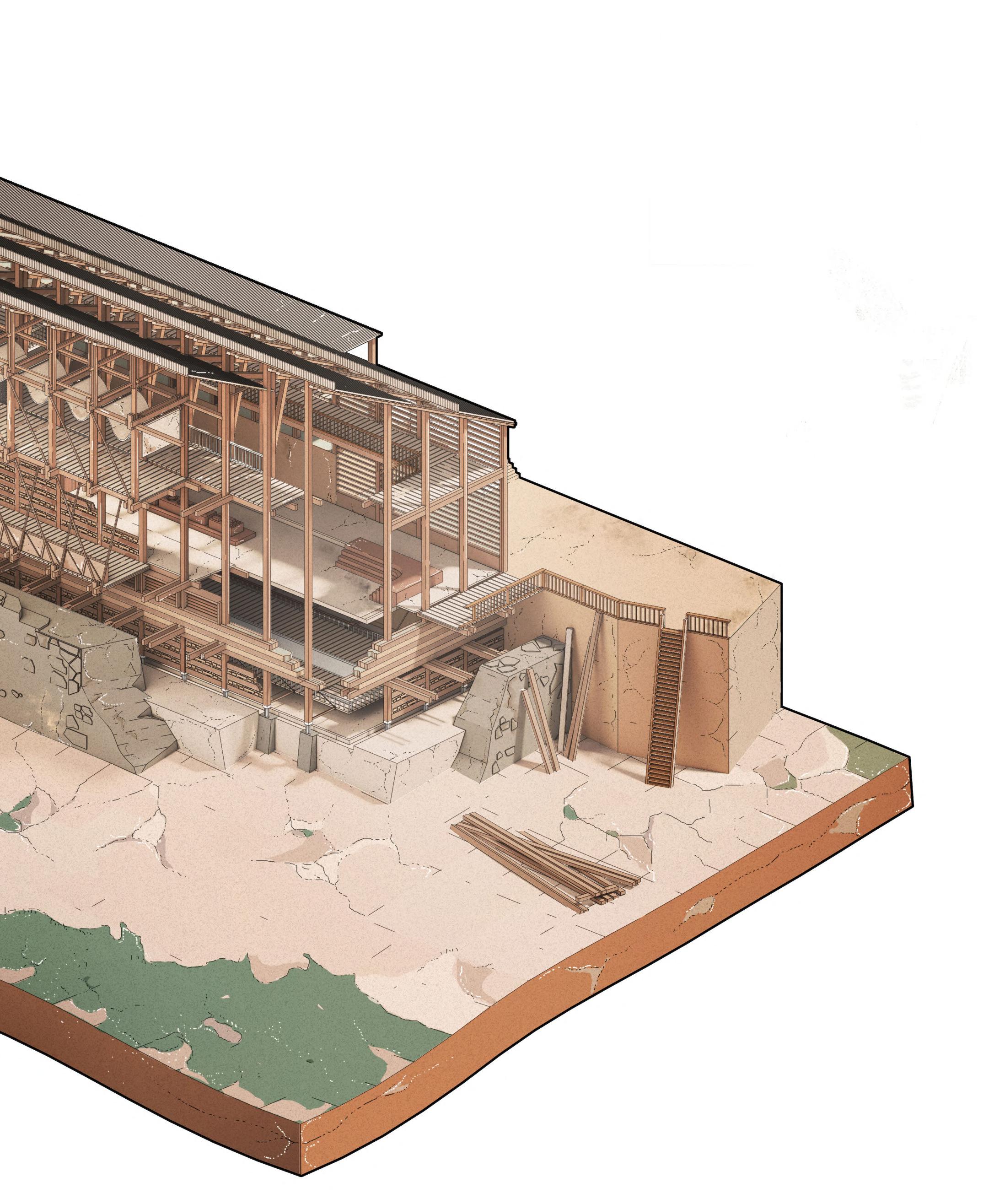 B.
B.
A A B B 70 BARC0174 _ AAD1CHAPTER 3 _ DESIGN DEVELOPMENT
3.08B
Figure
Figure 3.08C
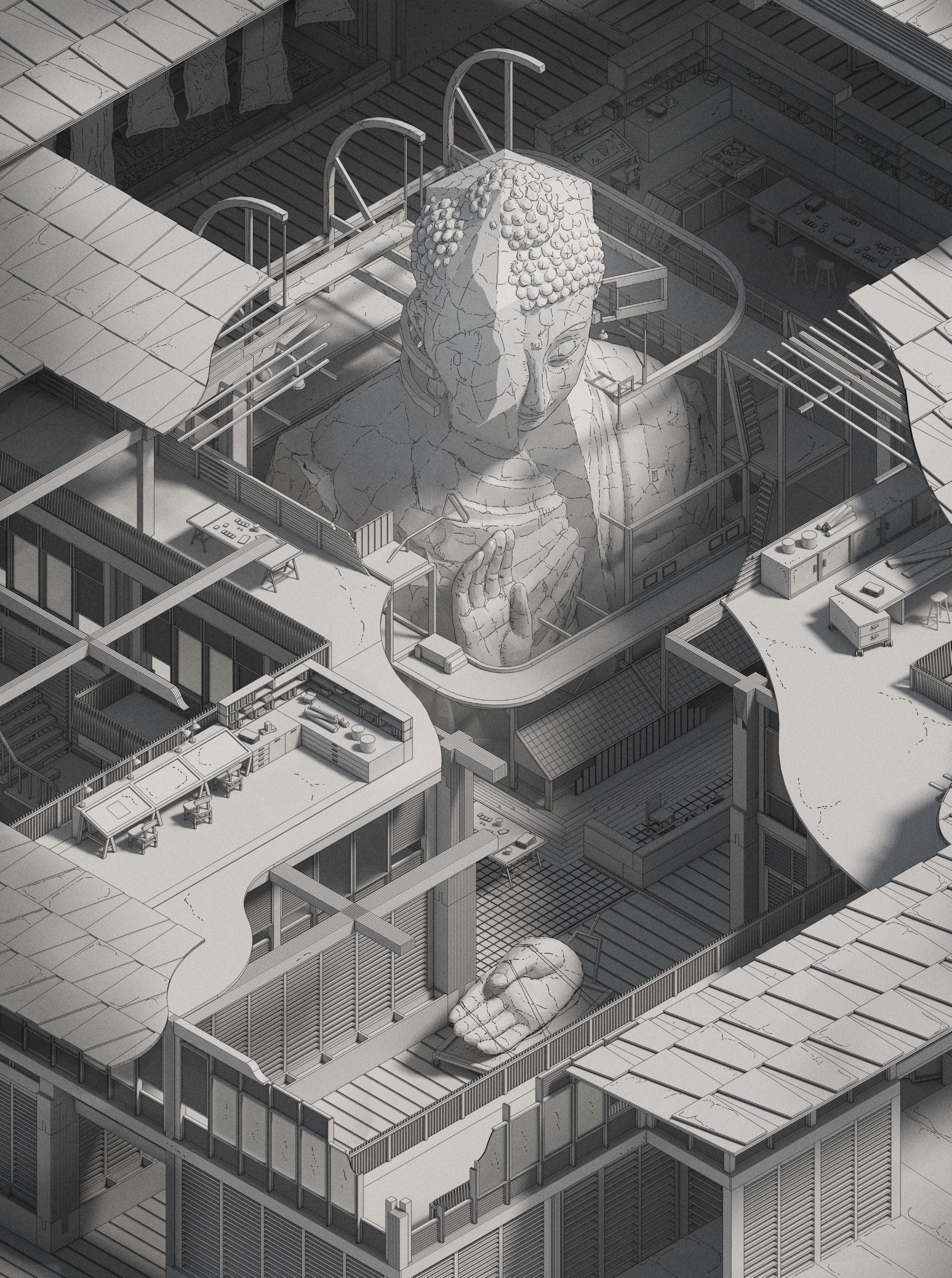
Main Courtyard:
CENTRAL BUDDHA SCULPTURE
An isometric view of the campus’ main central courtyard displays a snapshot of the intersecting programme of workshops, teaching and exhibition spaces, and the temporary scaffolding used to construct the central Buddha sculpture. The Buddha’s head sits slightly above the void framed by the overlapping roofs, creating the illusion of a halo from a distance. This aims to give the campus a stronger spiritual presence in Lhuentse Town.
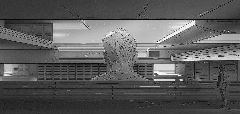
LHUENTSE SCHOOL OF CRAFTS 04 Chapter LHUENTSE SCHOOL OF CRAFTS 72 BARC0174 _ AAD1
Building Genesis
Central Courtyard
The site’s boundary is offset from a large central courtyard that serves several functions as the main gathering space, outdoor workspace and exhibition space - accessible via any volume across the campus.
Perimeter Programme
The building’s programme of workshops, dining, sleeping and public information pixelate outwards from the central courtyard, at varied widths and lengths, to direct and frame views into the central courtyard, and the outside.
Cascading Ground
The ground floor is sunken into the earth creating a hierarchy between programmes, with the entrance and security at the lowest floor height, and workshops/dining/sleeping closest to the inclined terrain.
Extruded Mass
The central mass holds the three crafts’ workshop spaces, with dining, sleeping and the entrance sitting on the periphery. This hierarchy is emphasised by the difference in size between each volume.
Primary Form & Associated Programme
The previous massing is divided further into volumes of differing heights and scales, while introducing each to their respective programme. The massing targets a hierarchy that is responsive to the environment.
03. 05. 07. 09.
Roofscape
The scheme introduces an interplay of inward facing roofs that sit on top of each volume. Each of the roofs intersect one another, and use a central void to frame the interior of each space, creating a mixture of untempered and controlled internal environments.
Rectilinear Footprint
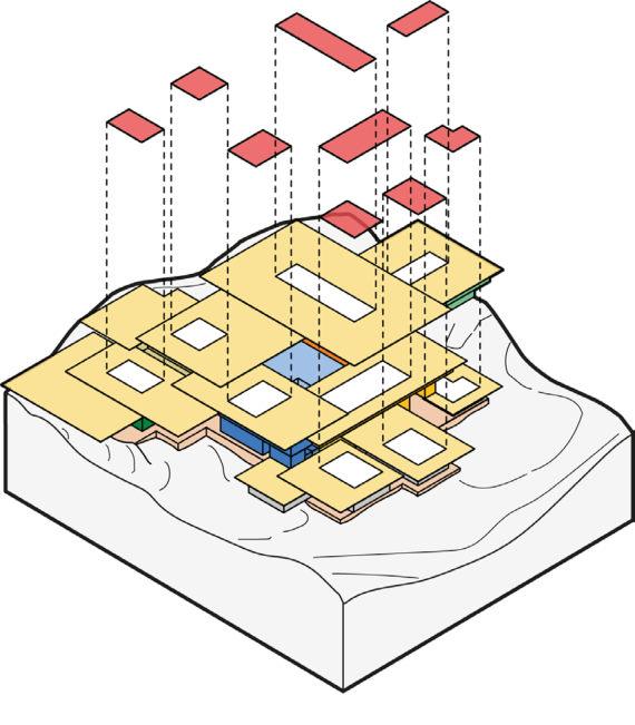
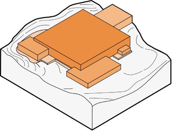
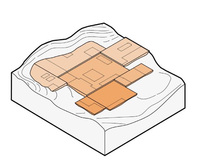
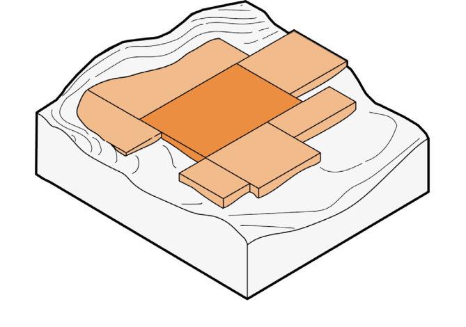
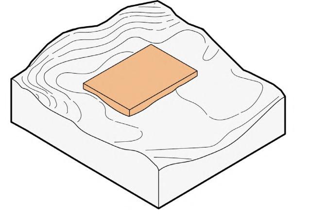
The campus uses the same visual language derived from Section 1.16/1.18, allowing for an overlap of cantilevered volumes, hence the use of an intersecting rectilinear footprint for each volume.
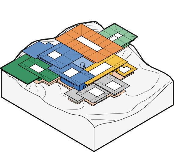
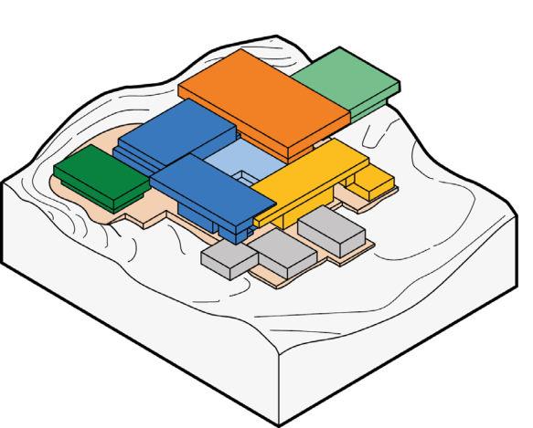
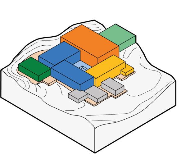
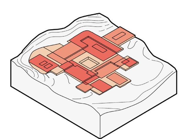
Framing the Central Courtyard
The building’s large Buddha sculpture creates a religious and symbolic centrepiece across the campus, and will be framed through a void subtracted from the central volume.
Introduction of Storeys
Each volume is refined further, introducing floors of differing heights to each space, allowing circular, staggered circulation between workshop spaces. Subtracting volumes allows natural light to enter at different angles.
Final Proposal
The majority of roofs use a slight angle to redirect and redistribute any incoming flows or rainwater and snow, creating a low-tech architecture that simultaneously celebrates and controls the extreme environment in which it sits.
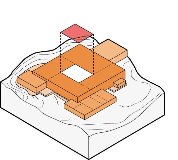
01.
02. 04. 06. 08. 10.
Section 4.01 73
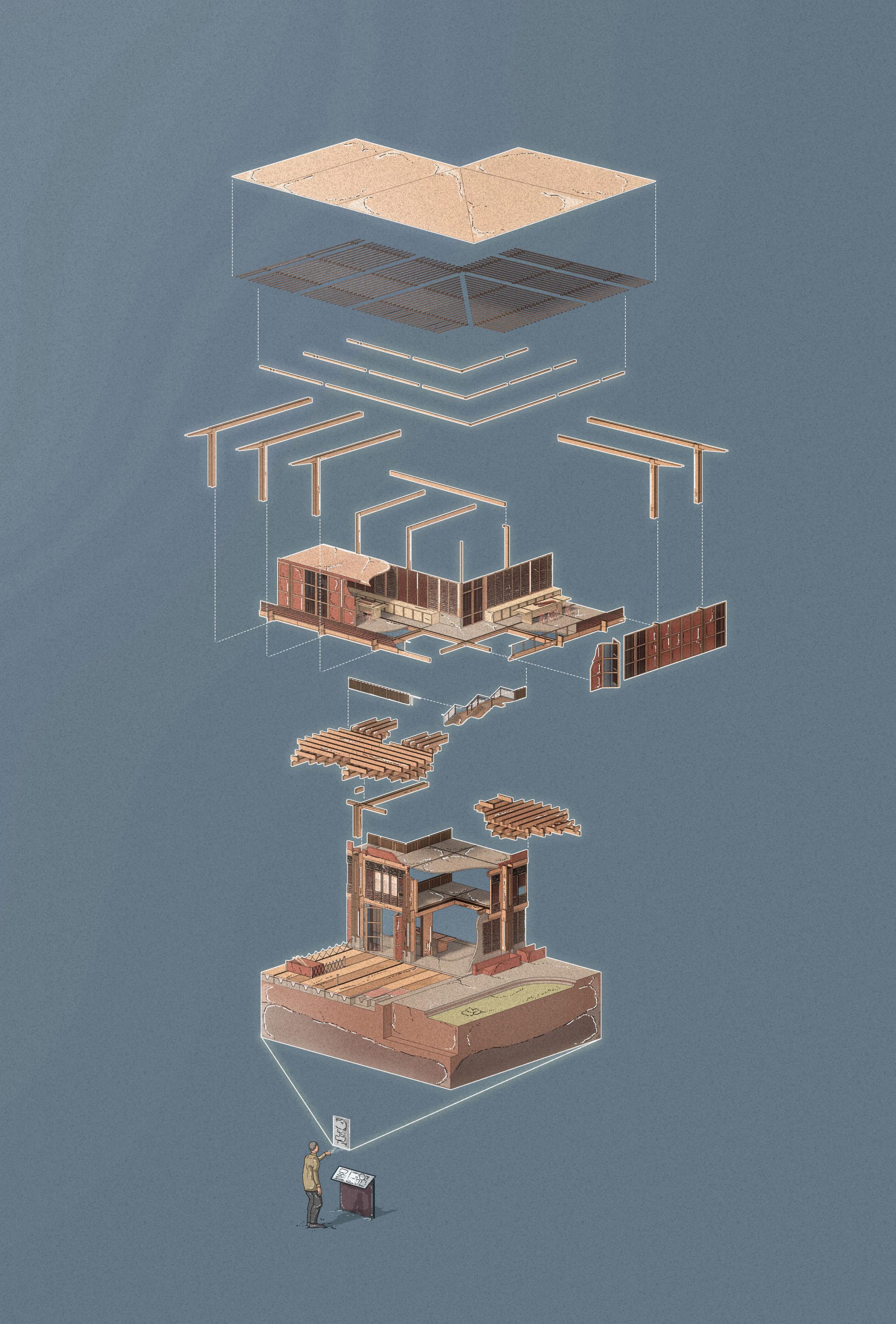
Massing Strategy
Roofscape
The thin, inward facing roof planes are constructed from slate roof tiles, similar to the initial precedent study of Aukta House. This helps to catch snow and rain, preventing runoff, and helping to redirect snow and rain for greywater use via channels across the building.
Workshop Spaces
The carpentry, painting and textiles workshop spaces frame the central courtyard which includes the large Buddha sculpture. Each are connected via stairs, walkways and lifts. The carpentry volume is the tallest, with the textiles and painting workshops each divided into two for smaller scale class and group learning exercises. Upper storeys are used predominantly as classrooms with the ground floor used as provision for practical exercises. The central courtyard also functions as a large outdoor workshop space that can be shared by all three crafts’ volumes.
Periphery Programme
The dual purpose dining/auditorium volume, shared student and staff dormitories, entrance and security sit on the perimeter of the workshop spaces. This arrangement intends to create a pixelated effect that expands outwards and creates a visual hierarchy denoting the importance of the workshop spaces in the centre with amenities on the perimeter. While each of the workshop spaces are connected via walkways and a circular circulation route, the periphery programme sit as independent volumes, creating a separation and hierarchy between work and amenity.
Central Courtyard
While the central courtyard is enclosed by the large volumes, the perimeter of the cascading ground floor is integrated with the landscape to provide multiple exit routes, as well as a prominent public entrance at the fore of the campus. The rear of the campus engages closely with an inclined terrain, providing a more secluded zone for servicing provision.
Key
Carpentry Workshop
Textiles Workshop
Painting Workshop
Dining/Auditorium
Dormitories
Entrance
Security
Walkways & Circulation
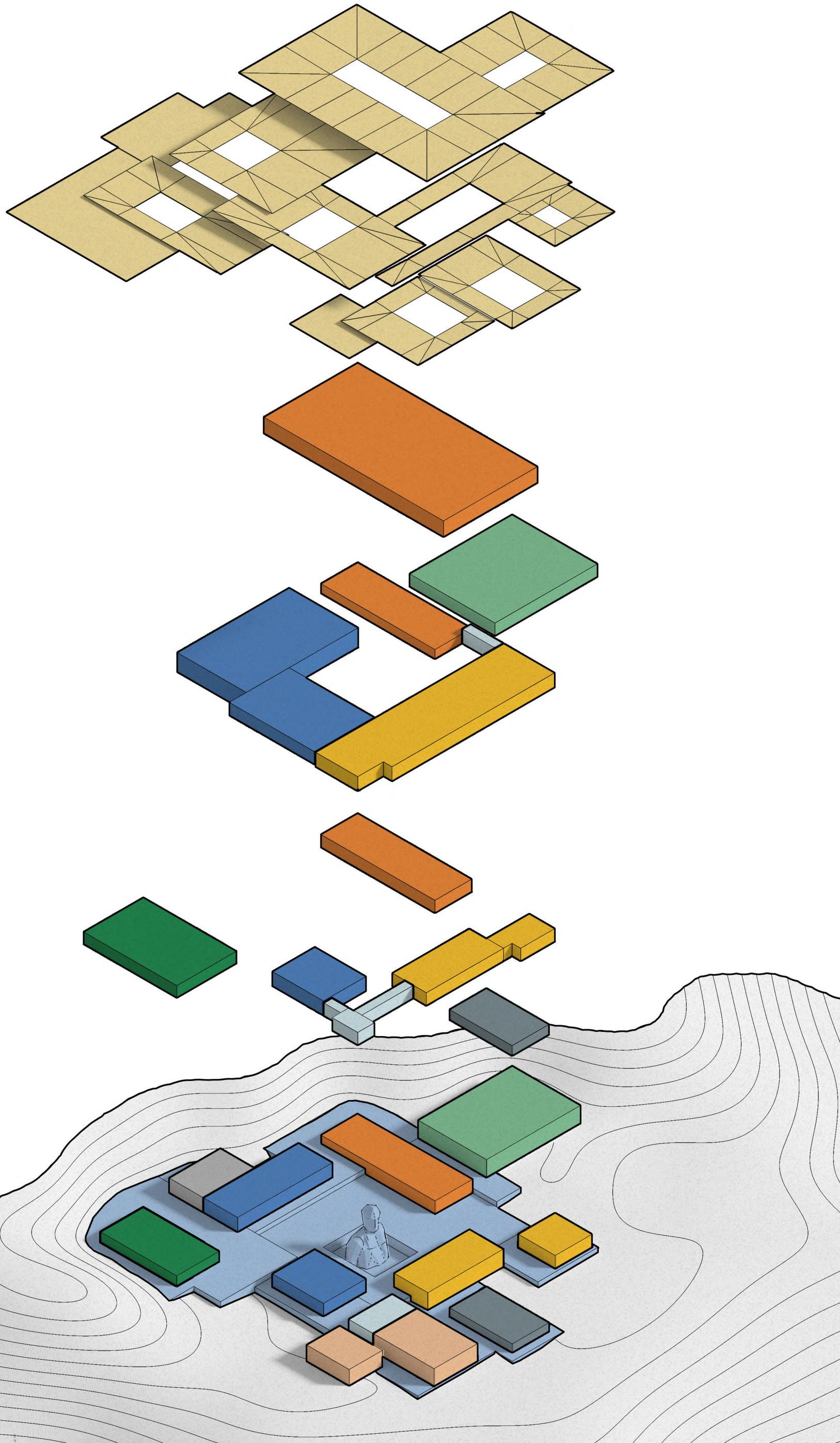
Servicing
Central Courtyard
Roofscape
Section 4.02 75
Level 00
Level 01
Level 02
Level 03 Roof
Roof
The intersecting roof planes use central voids to frame spaces, allowing natural light to flush into the interior. This allows the climate to be harnessed as a navigation mechanism across the campus.
Third Floor
The carpentry workshop is the only volume with a third storey, and significantly acts as a vantage point across the campus and landscape, creating a reward for public/staff circulating to this level.
Second Floor
The shared public, student and staff circulation route extends to the second storey, of which each of the workshop spaces are connected. Much like the ground floor, the second floor’s generous spatial provision allows for high occupancy rates. The dormitories are divided by a separate access route.
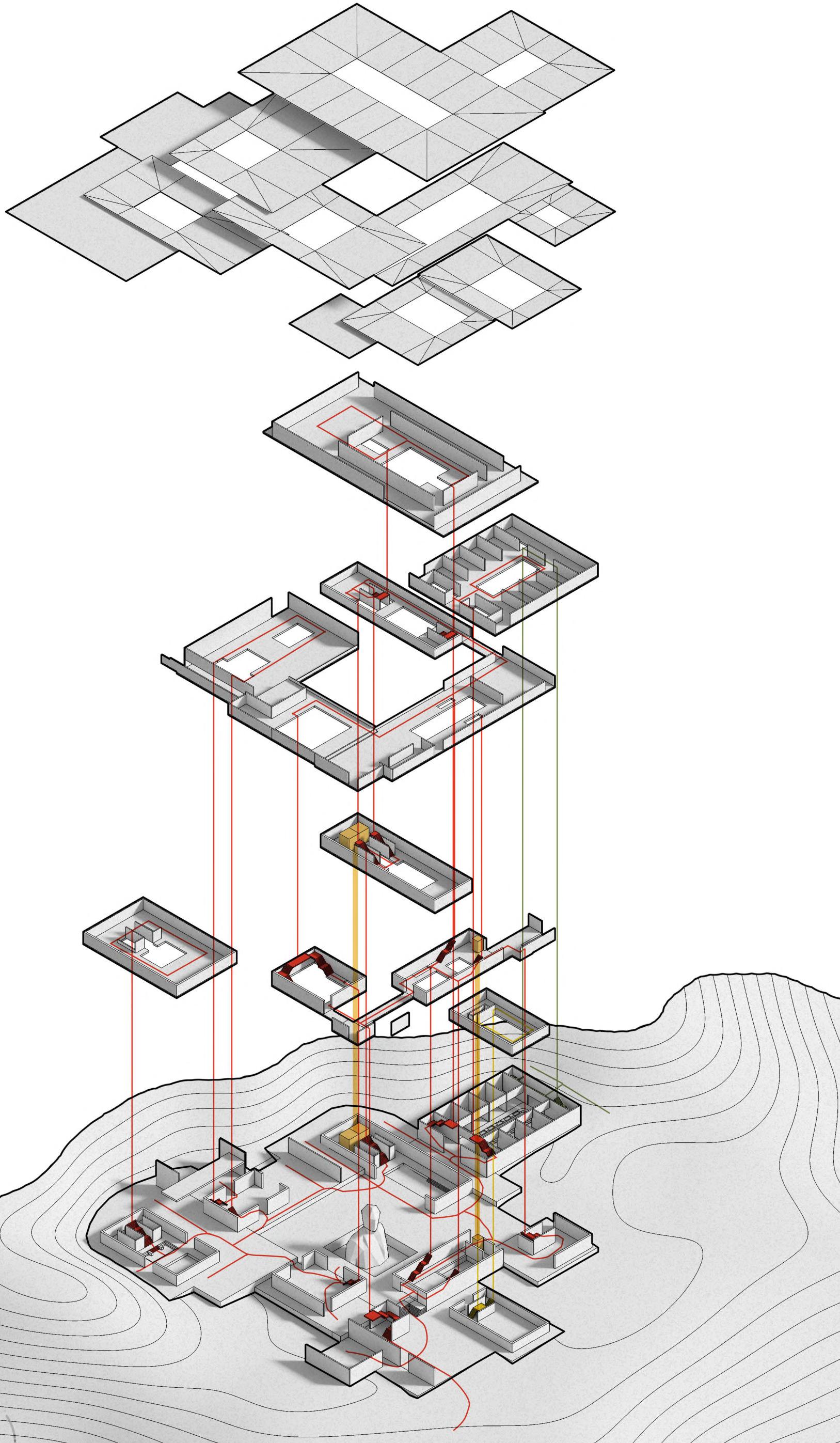
Ground & First Floor
Public and staff circulate across the campus through a largely circular route (dictated by the prominence of the central courtyard) including the use of lifts for disabled access. The open nature of the campus creates several service access points, exit routes and good escape routes in the event of a fire.
4.03 _ Programme & Organisation 76
Access & Circulation Strategy
Key Public Stairs/Circulation Public Lifts Staff Stairs Fire Escape Stairs Public Entrance Service Access/Points Exit Points Level 00 Level 01 Level 02 Level 03 Roof
Section 4.04
Overall Structural Strategy
STRUCTURAL OVERVIEW
This following pages primarily examine the construction of the carpentry workshop, roof, dormitory, central courtyard, and the adaptation of Kath Khuni through the introduction of vertical glulaminated members and a dry stone/timber composite, used both structurally, and as infill. The chapter also gives an overview of the building’s structural integrity and its use of concrete foundations in combination with glulam and dry stone. This resists loads from water and the climate, contributing to a system that is easy to assemble by local labour.
GLULAM
The building explores the transition from tool age to machine age timber in a remote location, and the appropriate material choice.
DORM
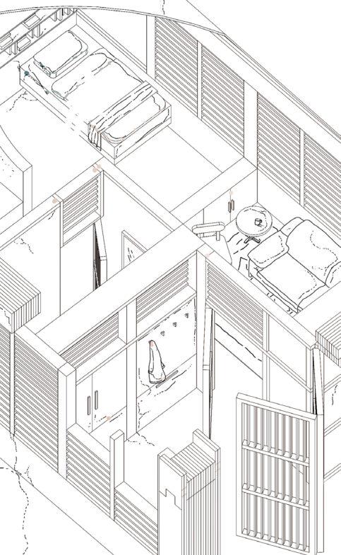
STUDY
A study of one of the dormitory zone’s rooms explores the low-tech wall build up of 300mm sheep wool insulation and locally sourced 300mm x 100mm deodar wood floor beams, roof purlins and a pine finished ceiling.
Roof Hierarchy
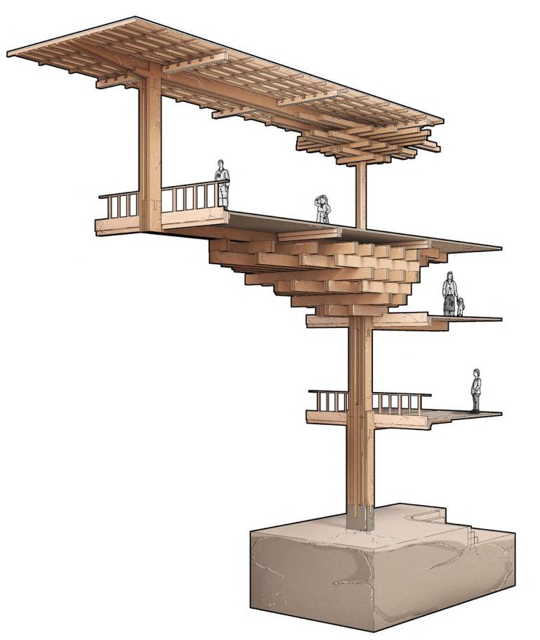
Glulam rafters and purlins improve structural efficiency, while a waterproof membrane ensures good ventilation. Slate tiles can be assembled by hand.
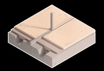

FOUNDATION AND DRY STONE /TIMBER COMPOSITE
Concrete foundations with integrated service pipes create a dry dock for the redistribution of greywater around the building (shown left). The concrete plinths are embedded with timber reinforcement underground to resist overhead loads when braced laterally. Later, locally sourced debris, dry stone and rubble are used as infill, increasing rigidity for the facade (shown above), while exercising an adaptation of Kath Khuni.
MAINTENANCE
The central courtyard houses a large Buddha sculpture which is constructed by staff and students alongside a demountable bamboo/ timber scaffolding system, creating a practical exchange between crafts teachers and students.
ROOF CONSTRUCTION
4.11
4.09
PRIMARY GLULAM

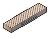
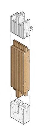
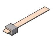
STRUCTURE
The use of a standardised structural fragment that is repeated across the building allows for ease of construction and helps establish a clear visual hierarchy prior to the addition of secondary and tertiary elements.
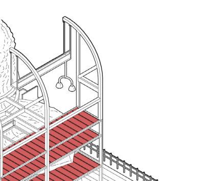
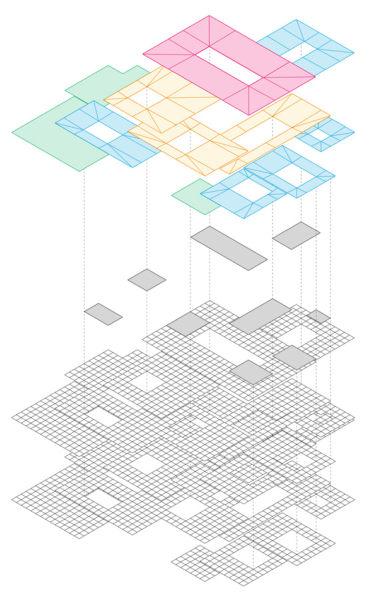

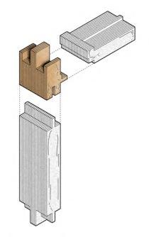
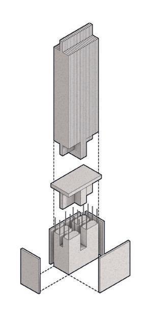

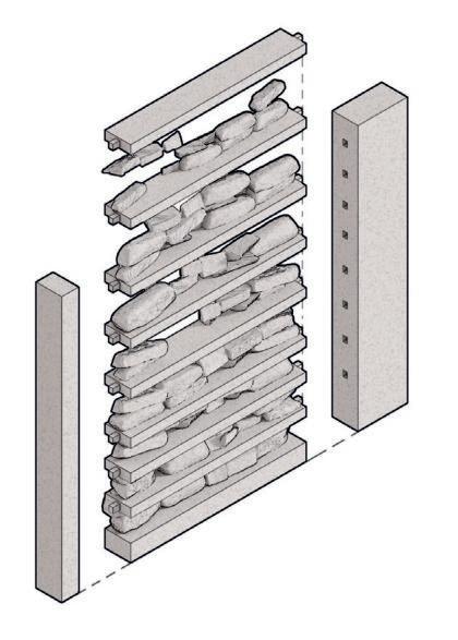
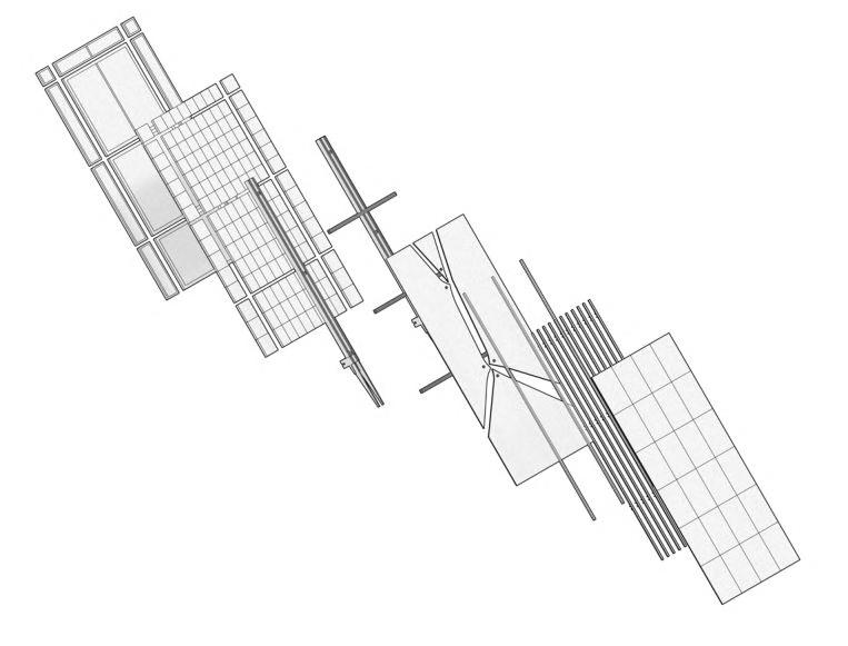
4.05 4.14 4.13 4.07 4.08
4.09
Multipurpose
Dining Hall & Auditorium
Local craftspeople and monks behave as teachers across the campus (shown right) while students are taught both tool age and new carpentry techniques. The workshop’s constructional hierarchy is explored, which opens up to an outdoor exhibition space and workspace.


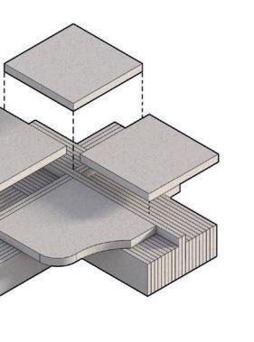
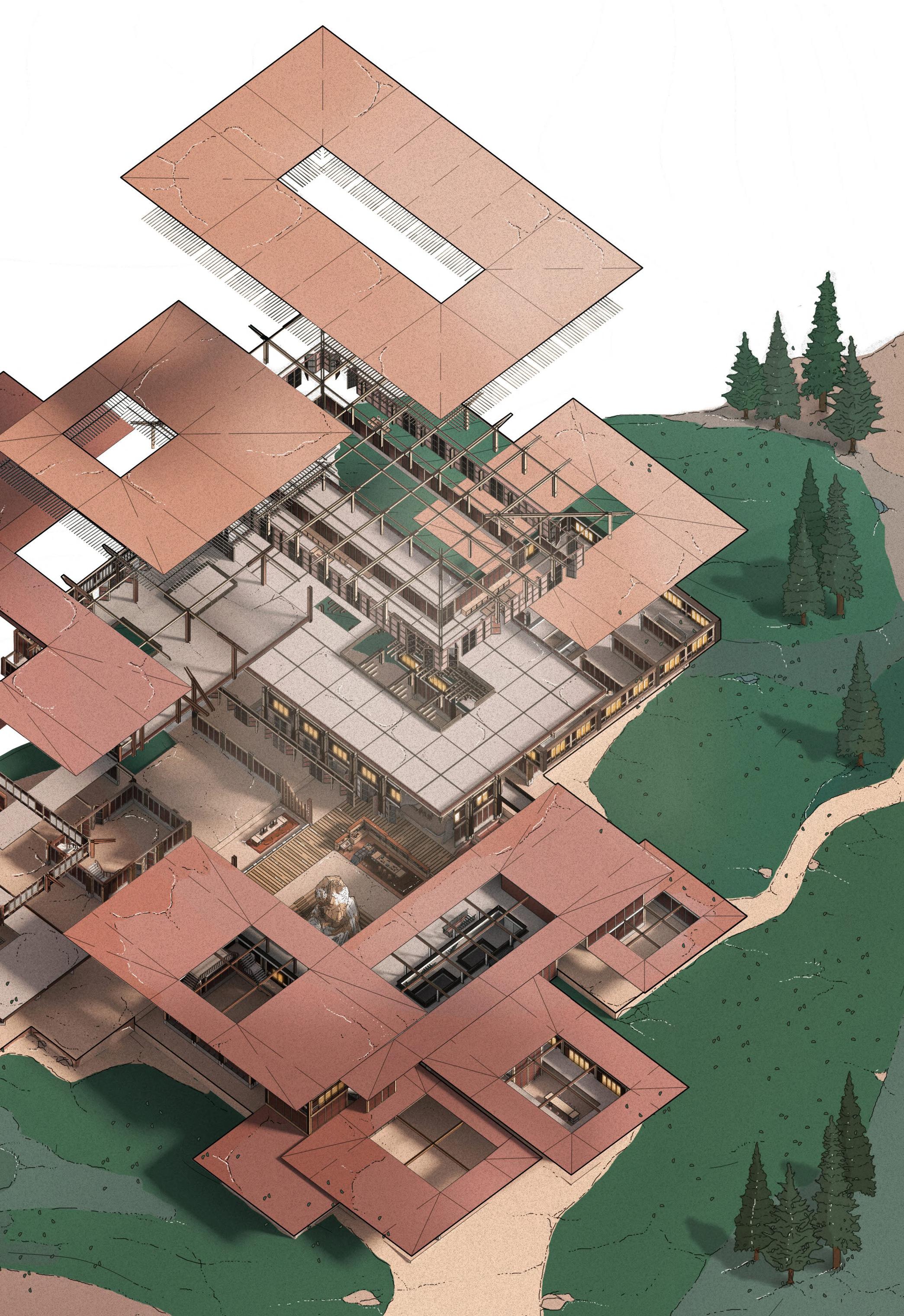
78
4.10
4.06
4.12
4.15
4.13
Entrance and Approach
Painting Workshops
Security
Main Entrance
Textiles Workshop
Textiles Workshop
Central Courtyard
Carpentry Workshop
Staff & Student Dormitories
CARPENTRY WORKSHOP
CHAPTER 4 _ LHUENTSE SCHOOL OF CRAFTS BARC0174 _ AAD1
CARPENTRY WORKSHOP MECHANISMS
Excavation & Foundation
The site’s geology formation reduces the risk of moisture exposure to foundations, while reinforced concrete slabs create an additional layer of protection. The proposal considered existing foundations (shown right) as precedent.

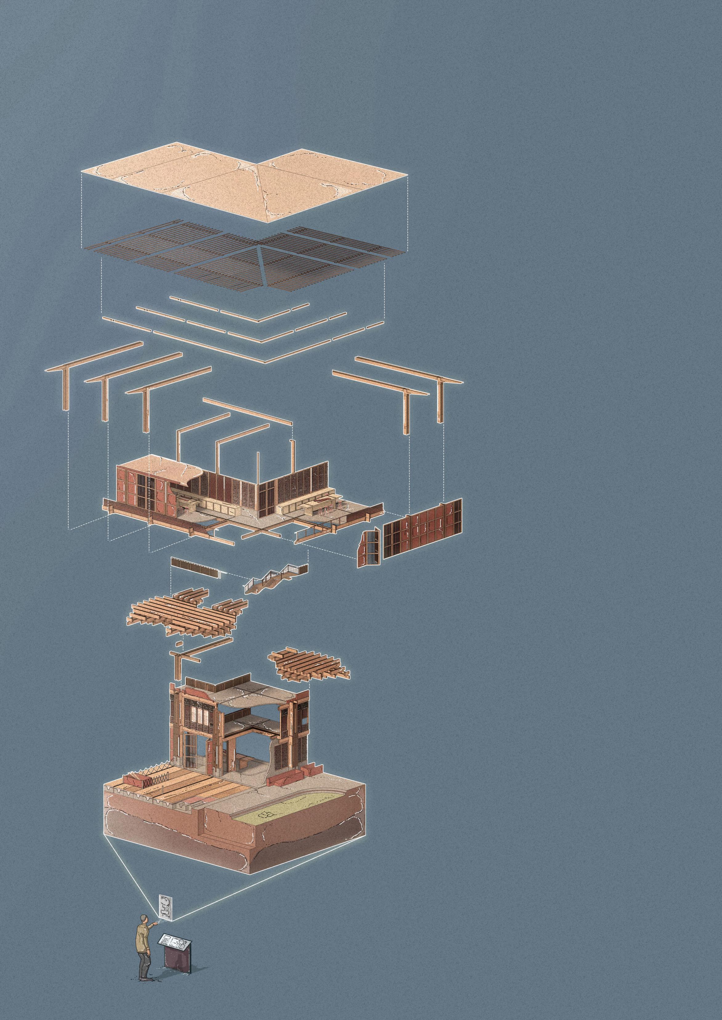
CARPENTRY WORKSHOP FRAGMENT
The use of concrete as a foundation in the carpentry workshop and across the entire building protects the primary glulaminated timber columns from moisture build up. Using a 3m x 3m structural grid, the timber/concrete composite allows loads to transfer to the ground and minimizes concrete usage for increased efficiency.
The existing site has some vegetation which should be preserved during the excavation and construction process. It also sits in a zone prone to earthquakes, located near to a series of flatlying overthrust plates (a reverse fault in which rocks on the upper surface move over the rocks on the lower surface). This creates various layers of sediment, rock and minerals.
1. Site geology is sampled and tested.
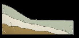


2. Site is excavated to create a flat terrain.
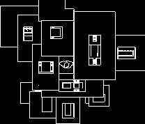
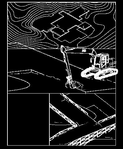
3. Excavated earth is used for fill adopting cut and fill approach.
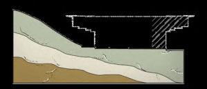
NATURE CONSERVATION
During the excavation process, sediment and topsoil extracted from the site can be solidified and used in stepped areas of the building as a fill, to minimize construction waste and protect the site’s vegetation.
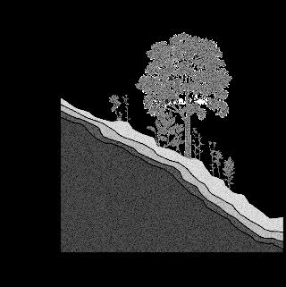
EXISTING FOUNDATION TYPES
Section 4.05 79
Revealing Plinth / Earth Interface EXPLODED ISOMETRIC BUILDING PLAN
GEOLOGY EXCAVATION
Raft Foundation Pier Foundation Pile Foundation Pad Foundation Lowers pressure on ground due to large surface area. Weak in earthquake prone zones. Lighter construction weight makes pier foundations more useful in timber buildings. Piles can be added to foundation to increase stability. Pile Cap Friction Pile 4. Workshop is constructed. Left fragment is shown dashed. Level 00 Level 01 Level 02 Level 03 Slate Roof Tiles Secondary Roof Rafters Deodar wood perpendicular cantilevered stack Concrete Foundation with Dry Dock and Poplar Decking Primary Glulam Columns Timber Roof Purlins Stairs with timber railings Precast concrete floor slabs Glulam Column & Beams Dry Stone/ Timber Infill Panels Excavation Process 1. Overall cut and fill approach. 2. Excavating the ground topsoil using diggers delivered to site. 3. Temporary platforms assembled. Dry Dock A. Precast Concrete Ground Slab B. Concrete Trenches C. Water Pipes D. Poplar Decking BA D C 1 2 3 Figure 4.05A
4.05B
4.05D
4.05C
4.05E
Figure
Figure
Figure
Figure
DRY CONNECTION
Lateral beams are inserted into deodar wood columns with wedges to increase stiffness. Alongside this, dry stone and rubble is infilled vertically.
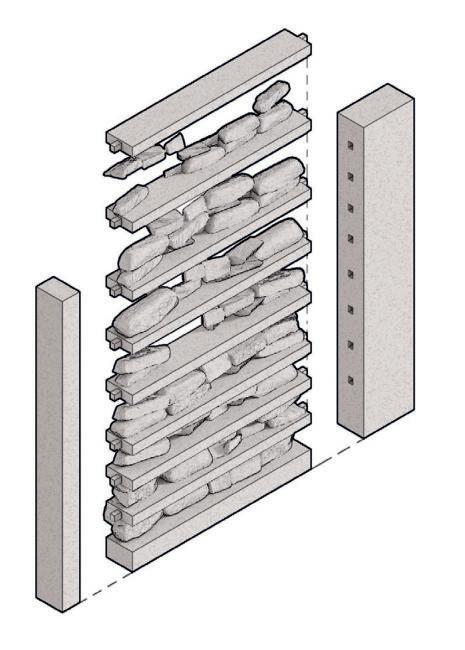
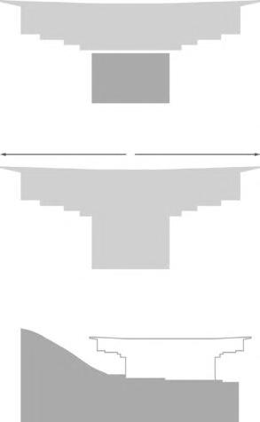
WET CONNECTION
Timber formwork is constructed for the plinth, after which concrete is poured in-situ, and the formwork is removed.
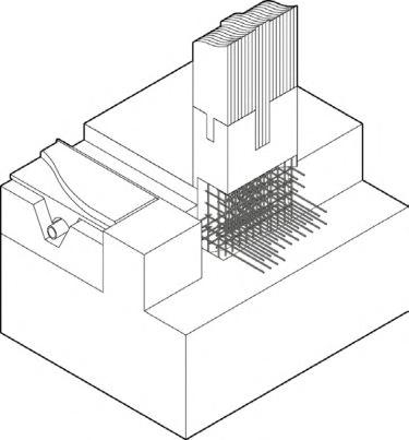
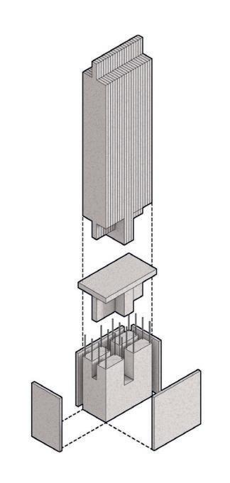
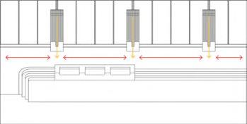
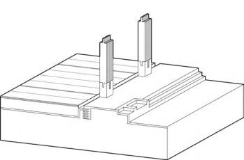
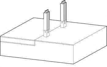
Pre-fabricated glulam columns are then inserted into the concrete foundation using timber reinforcement.
Dry Stone/Timber Composite
PRECAST CONCRETE FLOOR SLAB
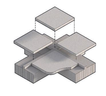
INTEGRATED APPROACH
CARPENTRY WORKSHOP SECTION
Demonstrating the implementation of each of the above systems, the carpentry workshop uses a hybrid constructional hierarchy of glulam, dry stone and concrete. Timber reinforcement is slotted into the ground floor concrete foundations.
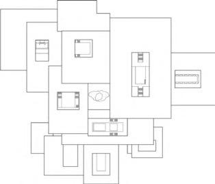
Key Project Factors
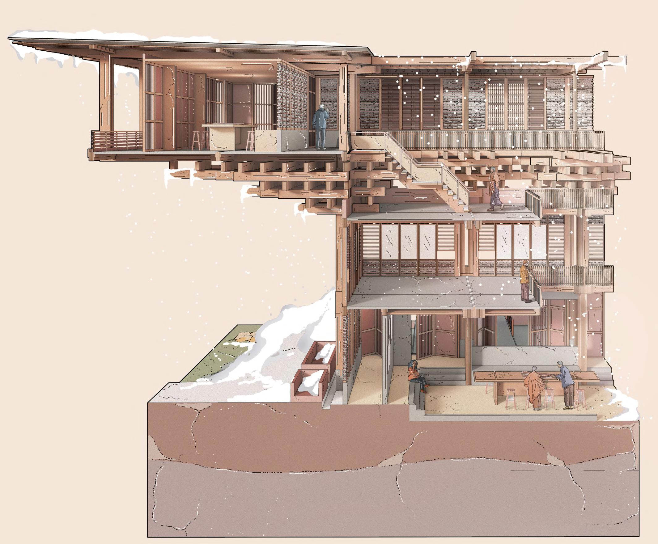
Section 4.0680
Precast concrete floor slab The reinforced concrete foundations act as stiffeners, resisting lateral loads including wind, which is common in
region. Stepped landscaping and reinforcement creates an embedded foundation that is more strongly integrated into the landscape. Ground Concrete Foundation Glulam column Concealed Bracing Typical Ground Floor Plinth Concrete plinth with reinforced timber Connected in perpendicular direction Embedded Structure Glulam beams
the
A. Plinth Superstructure
B. Cantilevered Stack
Water Redistribution Channel
C. Cascading Ground
A.
B.
C.
A 4 1 2 3 A 1 2 3 4
Carpentry Workshop Fragment
Figure 4.06A
Tool Age to Machine Age Timber
USING ENGINEERED WOOD TO CREATE A HYBRIDISED SYSTEM
By exploiting the different methods of sawing timber to harness the grain direction for structural capacity, a hybrid system can be introduced to increase an integrated structure’s strength and durability.
SAWING VARIATIONS
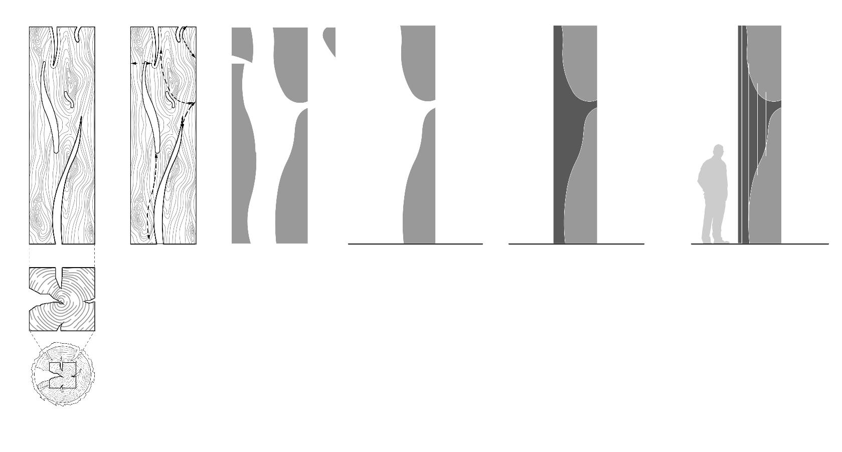
True Radial Cut Through and Through Cut or Crown Cut
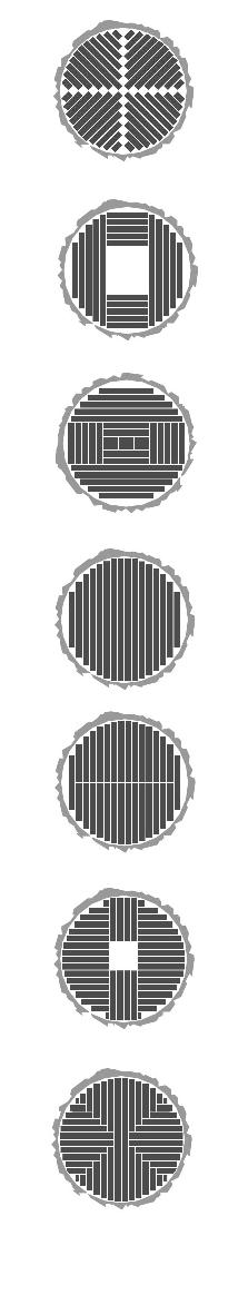
Plain Sawn


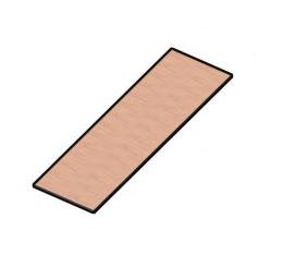
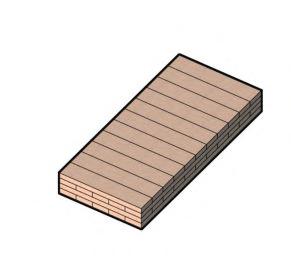
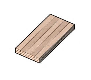
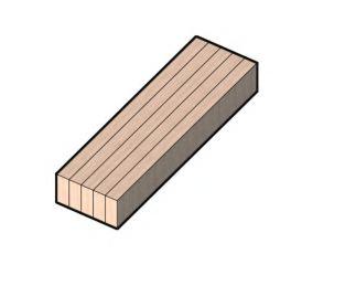
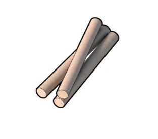
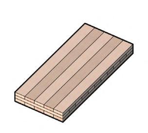
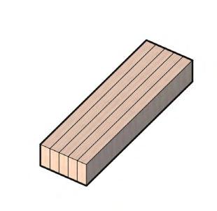
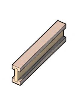
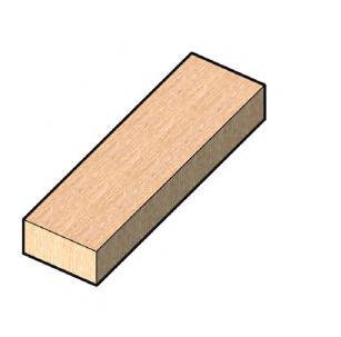

Cut for Board and Structural Timber
Quarter SawnBillet Sawn Cut to Maximise Radial Faces
HYBRIDISED MEMBER CREATION FOLLOWING STRESS FRACTURES/CRACKS IN WOOD
The above set of diagrams takes a conceptual approach to creating a hybridised member made of timber (light grey) and infill (dark grey). The wooden member is cut along naturally occuring cracks, creating an amorphic set of pieces, which are later infilled with timber reinforcement.
ENGINEERED WOOD PROCESS
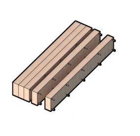


ENGINEERED WOOD
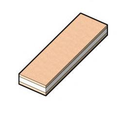
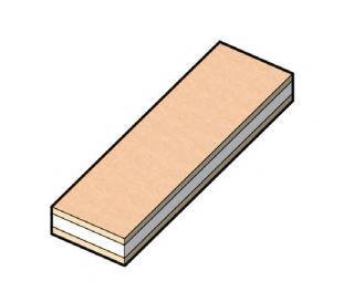
PARALLEL STRAND LUMBER LAMINATED VENEER LUMBER I-JOIST GLULAMSTRUCTURAL INSULATING PANEL CROSS LAMINATED TIMBER Beams/ColumnsBeams/Columns Glue Laminated Timber Plywood Oriented Strand Board Parallel Stranded Veneer Laminated Strandboard Laminated Veneer Structural Insulating Panels Cross Laminated TimberStress Laminated TimberNail Laminated Timber Fibreboard Chemically Treated Timber TYPE USEPROGRAMME Joist/BeamBeams & Tall Storeys Beams/ColumnsRoof/Wall/Floor InteriorInterior InteriorInterior & Exterior InteriorInterior & Exterior
LOGS TIMBER VENEERS STRANDS
Section 4.07 81
Figure 4.07A
Figure 4.07B
GLUE LAMINATION PRODUCTION PROCESS
Glue laminated timber is a strong, renewable and energy efficient engineered timber that has varied uses in building construction, as well as being weather and fire resistant and easy to install making it suitable for different climates and extreme terrains. Different grain direction allows functionality in compression and tension.
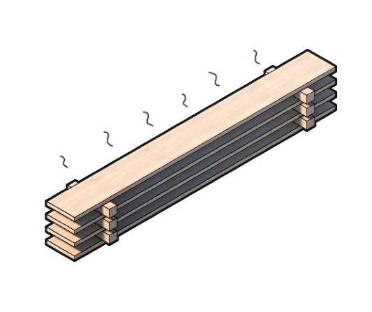
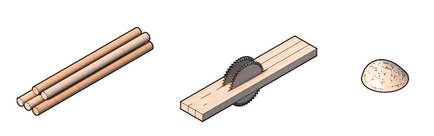
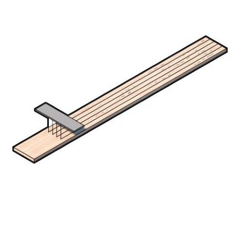


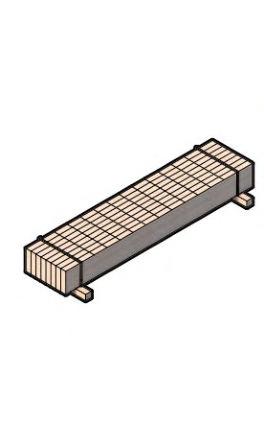
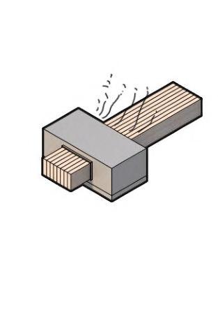
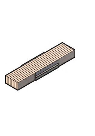 STEP 01
STEP 05
STEP 09
STEP 02
STEP 06
STEP 10
STEP 03
STEP 07
STEP 11
STEP 04
STEP 08
STEP 12
Raw material collected from tree
Material graded according to strength
Bonding under pressure
Raw material sawmilled and laminated into boards.
Finger jointing
Sawdust collected for energy recovery and Glulam product planed
Chips, sawdust and pellets waste collected for energy recovery
Laminate planed and sawdust collected for energy recovery
Pressurised gluing of layered slats
Cut material dried
STEP 01
STEP 05
STEP 09
STEP 02
STEP 06
STEP 10
STEP 03
STEP 07
STEP 11
STEP 04
STEP 08
STEP 12
Raw material collected from tree
Material graded according to strength
Bonding under pressure
Raw material sawmilled and laminated into boards.
Finger jointing
Sawdust collected for energy recovery and Glulam product planed
Chips, sawdust and pellets waste collected for energy recovery
Laminate planed and sawdust collected for energy recovery
Pressurised gluing of layered slats
Cut material dried
1 5 9 6 10 7 11 8 12 234 Longitudinal Tangential Radial Grain Direction Compressive strength Parallel to Grain Shear strength Parallel to Grain Tensile strength Perpendicular to Grain Glulam Manufacture 4.08 _ Material Sourcing 82
Glue application Packaging for distribution
Figure 4.08A
Primary Glulam Structure
STRUCTURAL ANALYSIS
The corner of the stacked column and cantilevered elements experience the most force. The distribution of forces also denotes a path of loads throughout the structure.
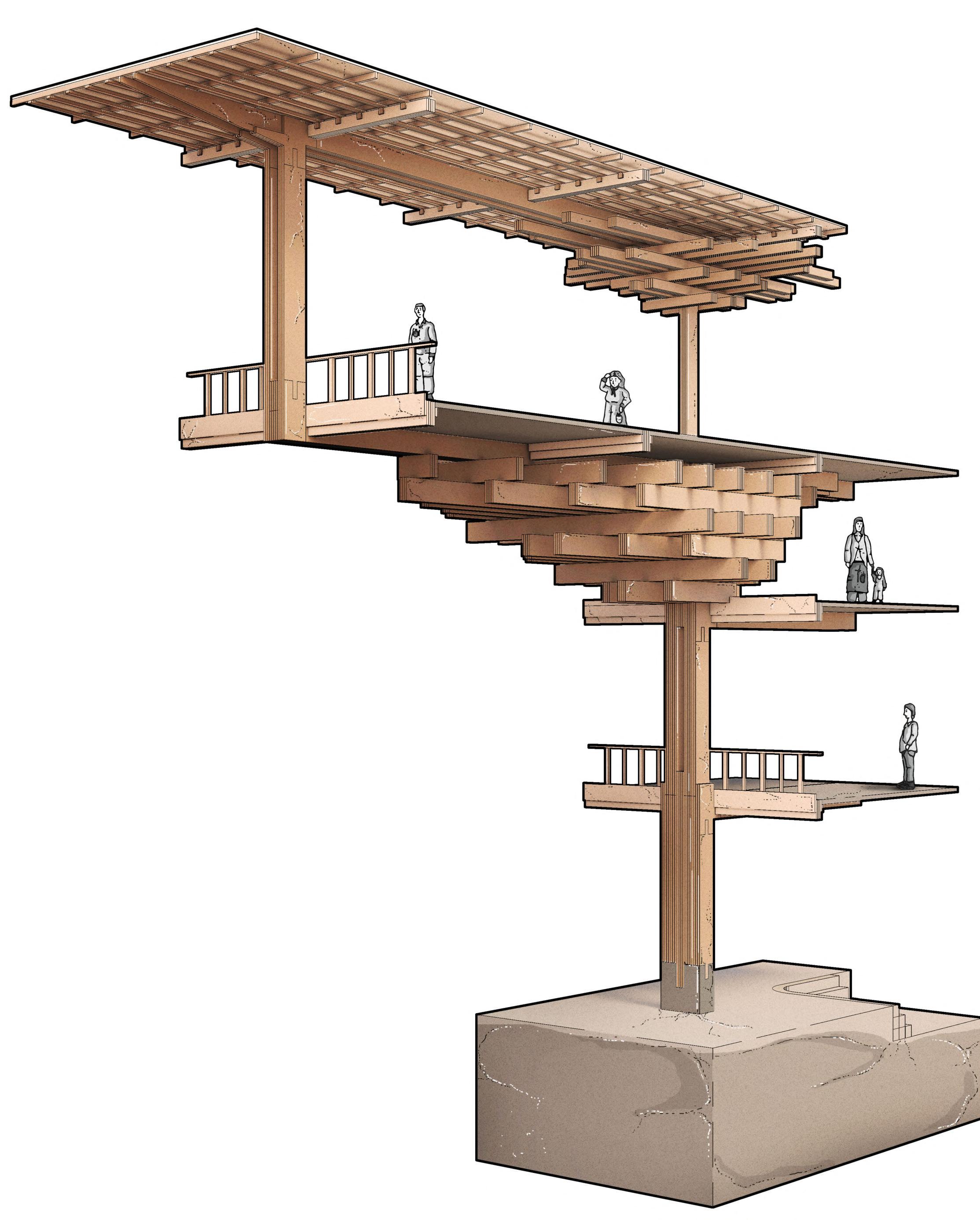
PRIMARY STRUCTURE
The use of a standardised structural fragment allows the repetition of the module across the building, creating both ease of construction and project delivery. The central tapered glulam column uses vertical gaps to reduce weight and helps develop a structural principle that expresses a clear visual hierarchy.
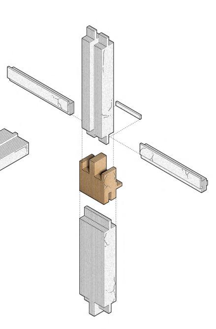

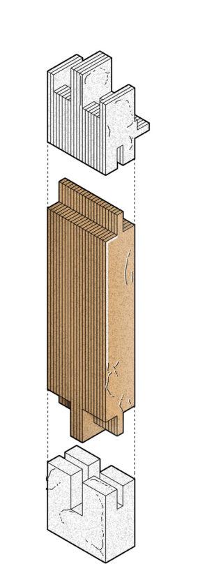
The primary glulam timber structure is assembled on site, using joinery that has been adapted from research into Dhajji Dewari construction. Corner pieces ensure the structure acts like a box during an earthquake and behave as locations for strategic strengthening.
CENTRAL COLUMN
Using a concrete foundation, the glulam’s lamellae are shaped to slot into place to create stiff connections. The increased interface also prevents the joint from
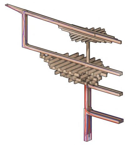
Section 4.09
Brackets create durability
A. Structure Base Joint
B. Column to Corner to Beam
C. Double Column Joint Compression Tension Supports
Joinery
A.
B.
C.
Figure 4.09A
ROOF TO COLUMN
The use of dowels that are concealed within the glulam frame help strengthen the structure. The use of a peg-like shape also introduces a ledge to mobilise full beam shear capacity, whilst allowing the column to have reduced tension capacity. The corner joint adapts Kath Khuni and Dhajji Dewari, enabling the system to achieve longer spans.
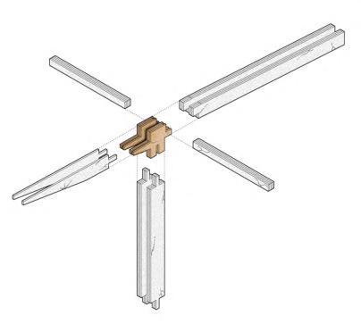
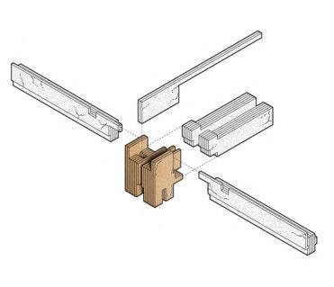
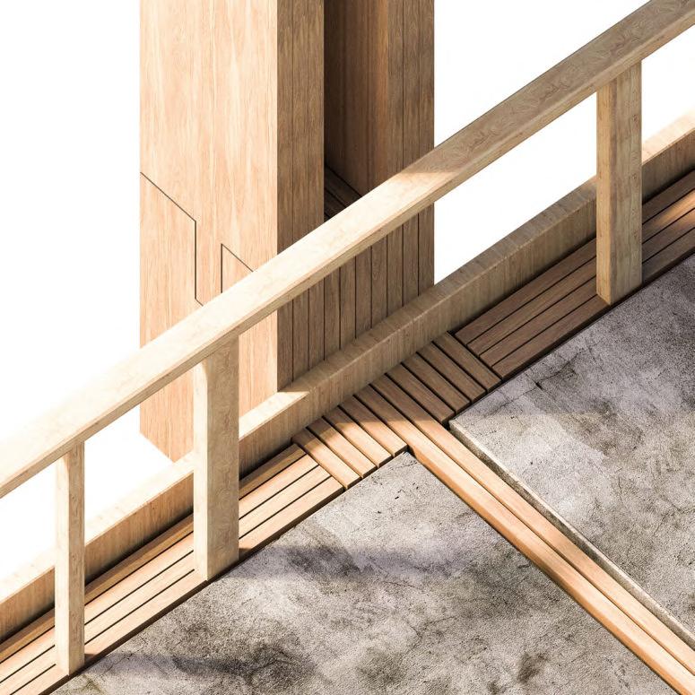
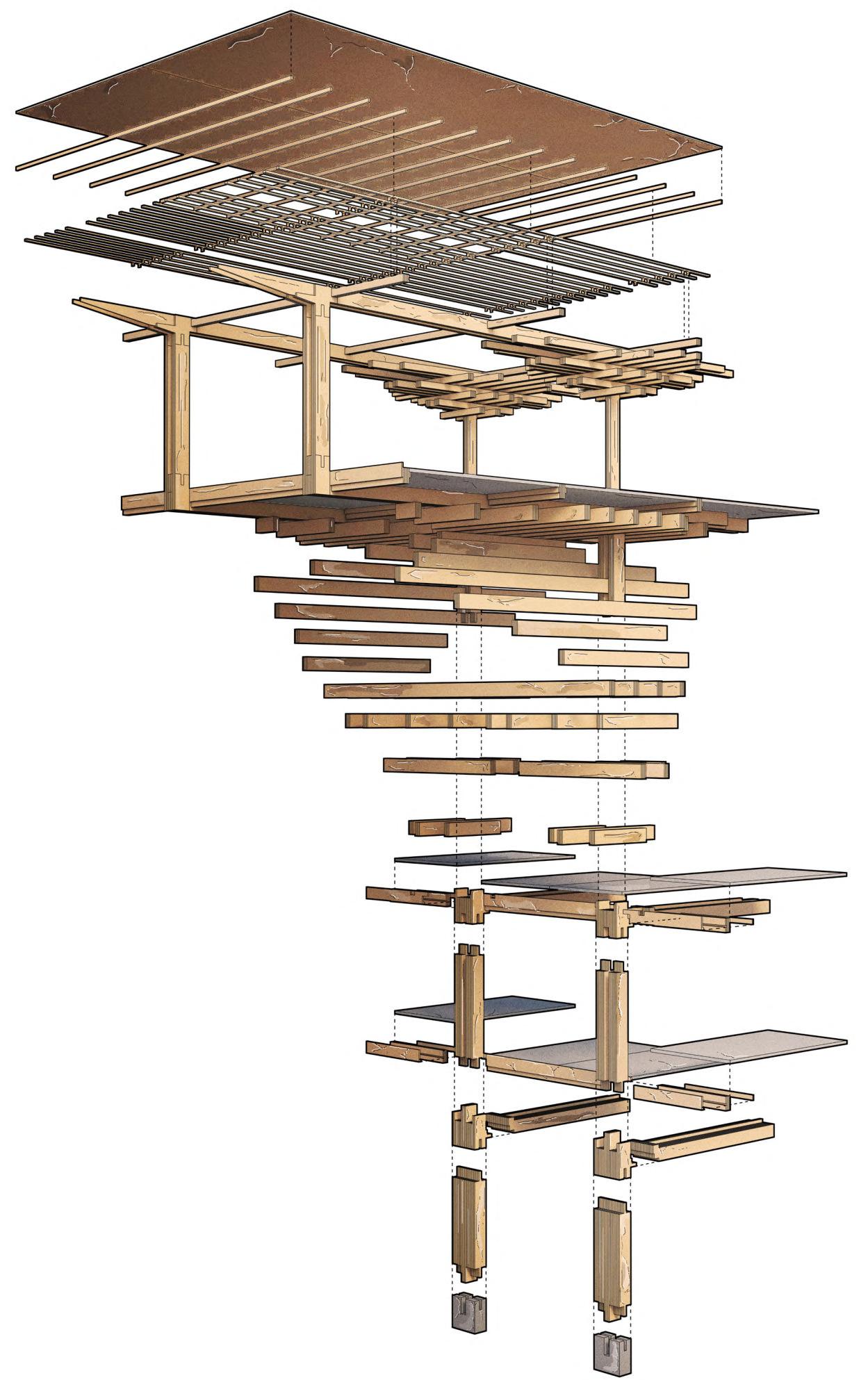
STANDARDISED COMPONENTS
A set of standardised components create ease of delivery and assembly. Each are categorised into
columns, beams, concrete foundations, precast concrete floor slabs and roof purlins.
Precast Concrete Floor Slab Key Detail
PRECEDENT STUDY
Kengo Kuma Architects’ Yusuhara Wooden Bridge Museum provides a useful precedent for an east Asian stacking system which uses a series of perpendicular cantilevered blocks, transferring load towards a single pier.
Structural Testing Loads Supports
JOINT DEVELOPMENT
Each of the lamellae within the glulam frame create more flexibility for the spans, along with integrated dowels and in some areas, timber reinforcement, creating additional stiffening for connections. The use of glulam also helps the elements to counteract cross-directional forces, creating rigid joints, while also creating extra movement and transferring vertical loads across the structure.
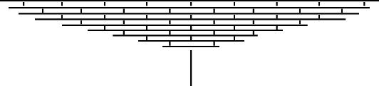
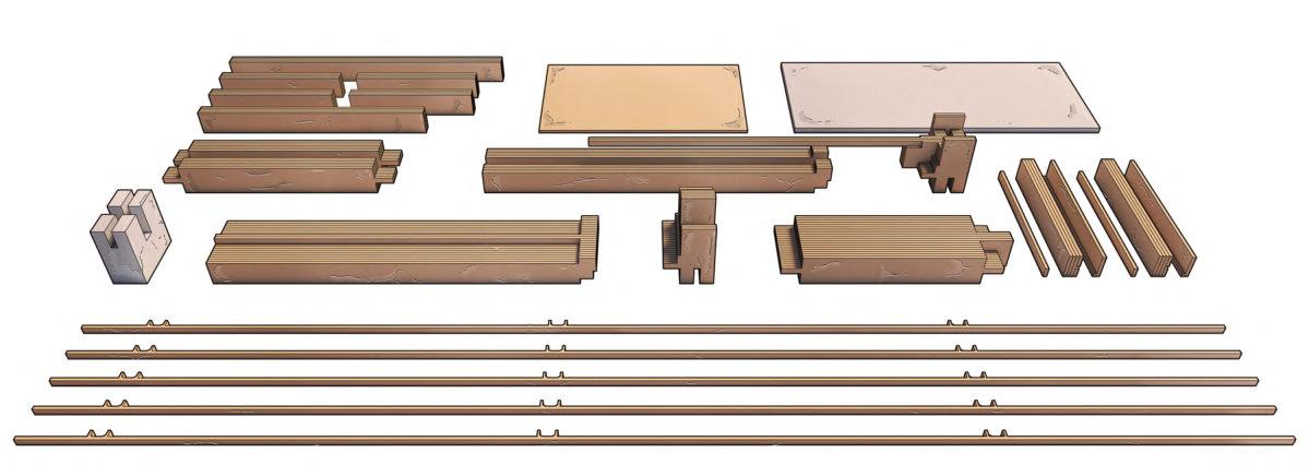
84
Precedent: Yusuhara Wooden Bridge Museum
D. Corner Joint
CHAPTER 4 _ LHUENTSE SCHOOL OF CRAFTS BARC0174 _ AAD1
Figure 4.09B
Section 4.10
Hybrid Constructional Hierarchy

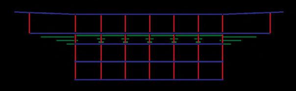


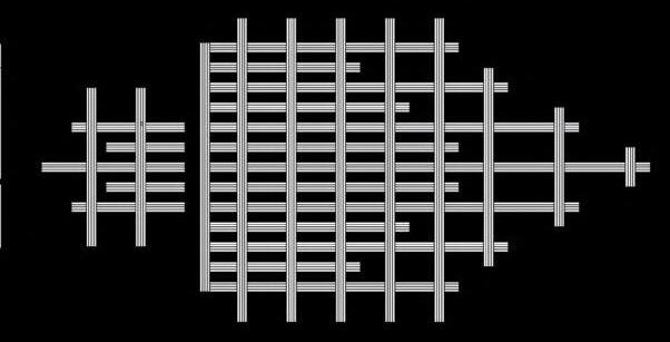

Native User & Toolkit

CARPENTRY WORKSHOP
Alongside the painting and textiles workshops, the carpentry workshop serves as the largest facility housing machinery, classrooms, and amenities including showers and food. The right drawing explores the use of the duplicated glulam structure repeated across the volume and the exterior ground which becomes a part of the workshop.
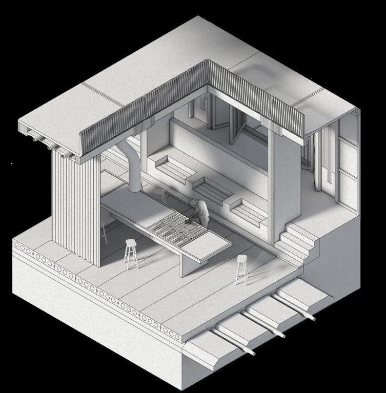
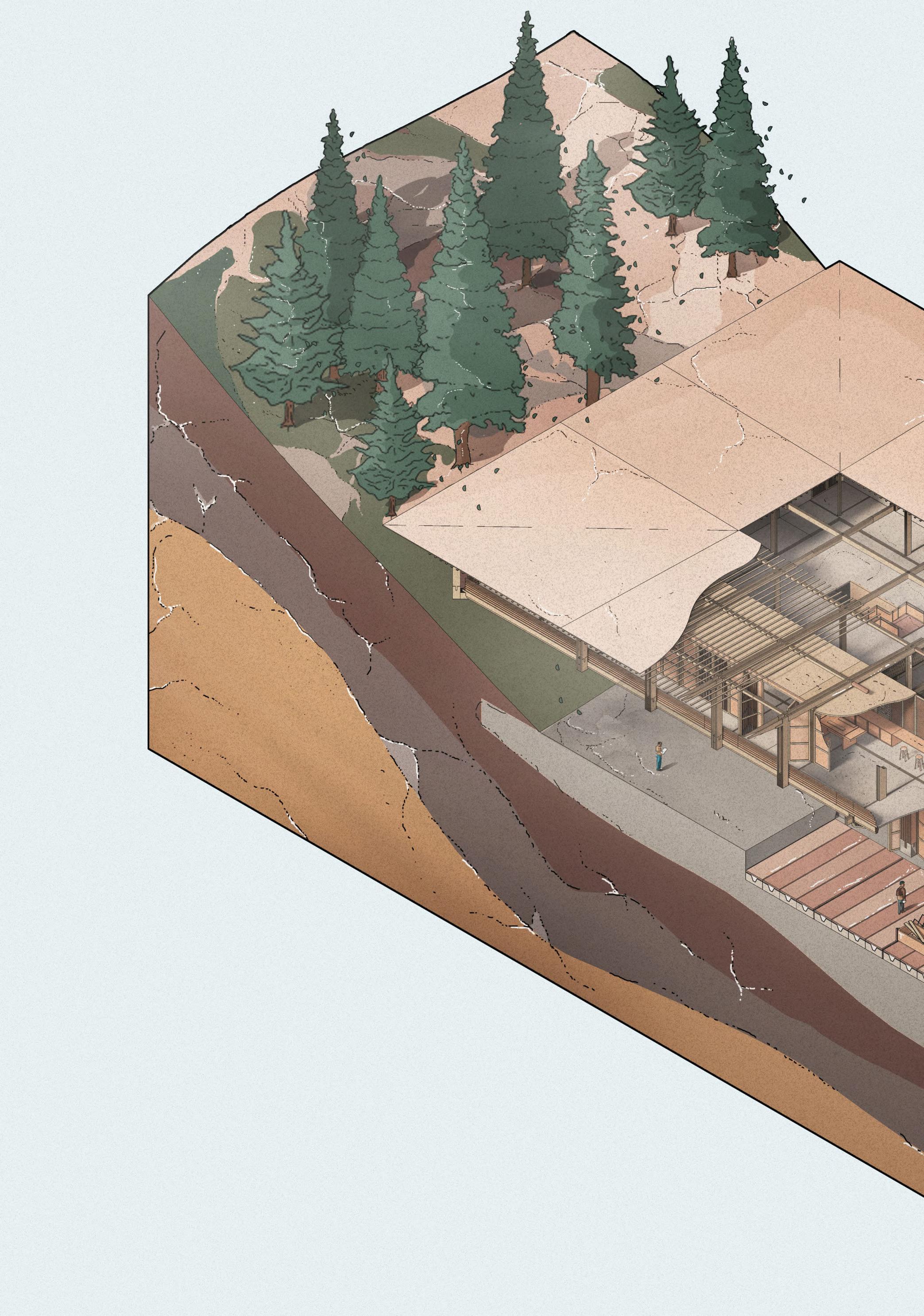
Structural Hierarchy
CONCEALED SERVICING
An extract of a student shown sanding planks of timber displays the use of the overhead extract and intake to limit the build up of sand debris. It is concealed in the overhead ceiling between the precast concrete floor slab and the Himalayan Pine finished ceiling. Underground pipes distribute water for sanitation across the building.
 Carpentry Workshop
C. Typical Vierendeel Truss which is adapted in proposal. D. Third floor composite truss system divided into bays. E. Hierarchy across workshop shown as primary columns (red), secondary concrete floor and roof (blue) and tertiary stacking support system (green). A. Tapered glulam column behaves as primary structure B. Stacking deodar wood using dowel connections on second floor creates support for third floor cantilever A. B. B. C. D. E. Extract and Intake Precast Concrete Concrete Trench Sanitation Pipes Timber shutters and dry stone infill Deodar wood frame Primary glulam columns and beams 3 1 2
Figure 4.10A
Figure 4.10B
Dry Stone/Timber Facade
HYBRID VISUAL IDENTITY
01 _ East Asian and South Asian influenced architectural identity
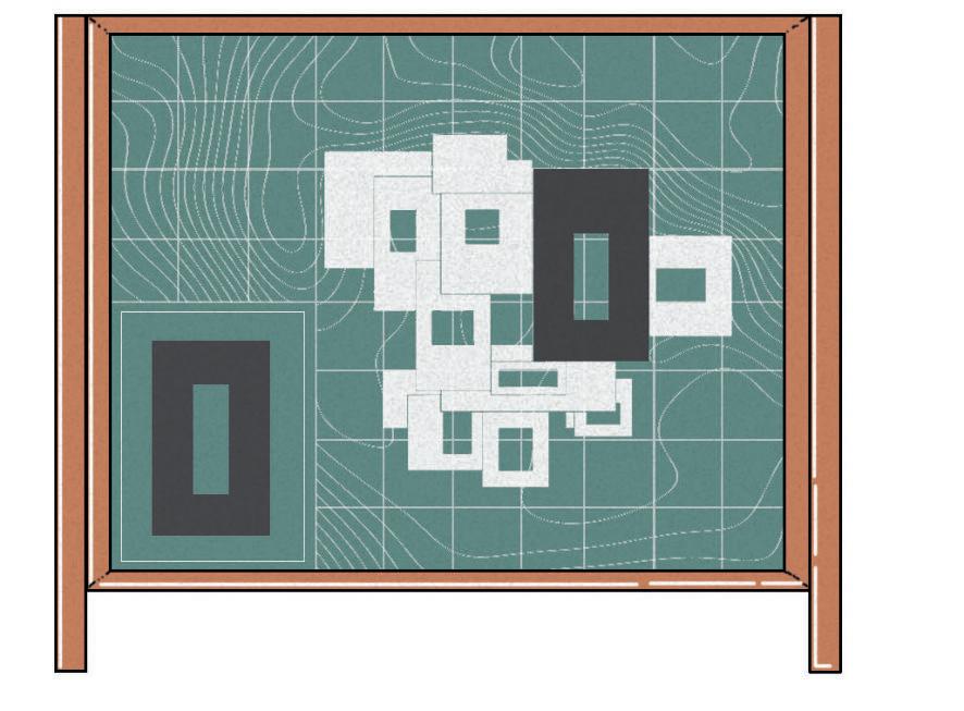
02 _ Hybrid users comprised of local craftspeople and foreign students
03 _ Dry stone and timber material hybrid
CASCADING GROUND
Initial studies for the ground looked at the reuse of removed earth by solidifying the mixture into rammed earth (shown above in red). A series of cascading levels looks at landscape integration, and the creation of pockets where channels of water can delineate thresholds between volumes, and direct users around the campus. The filleted edges are used at the edge of the carpentry workshop to offset its rectilinear shape.
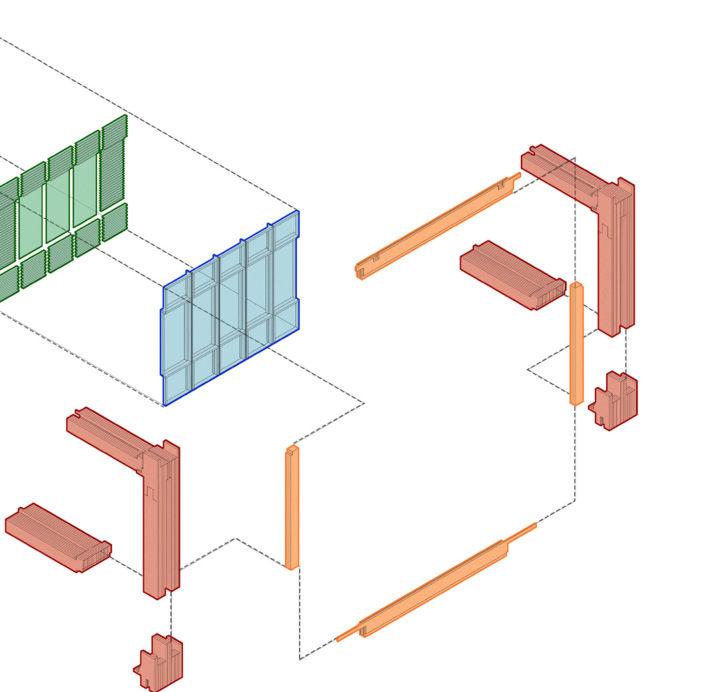
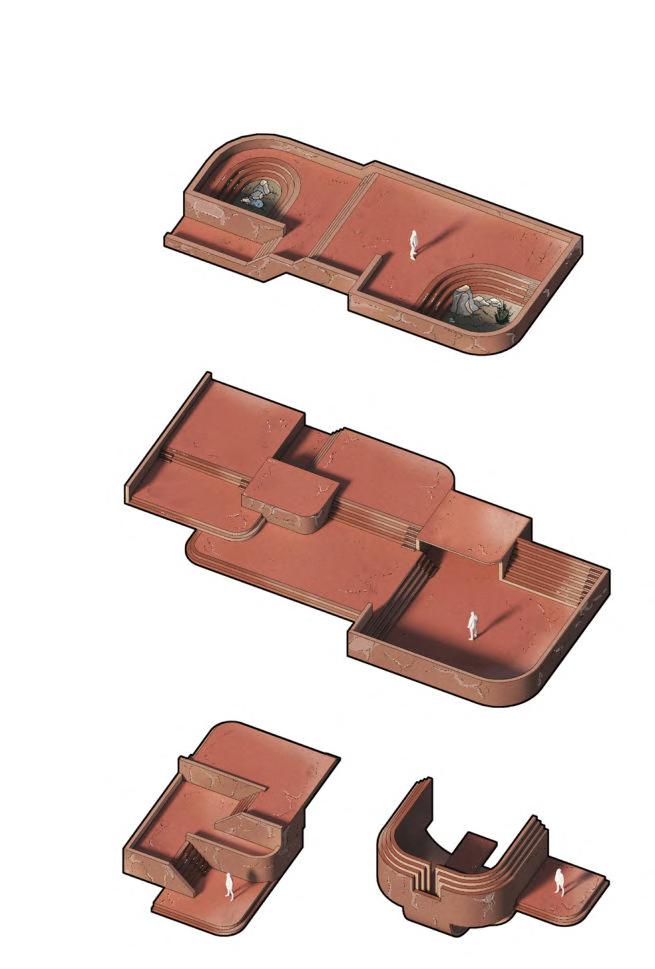
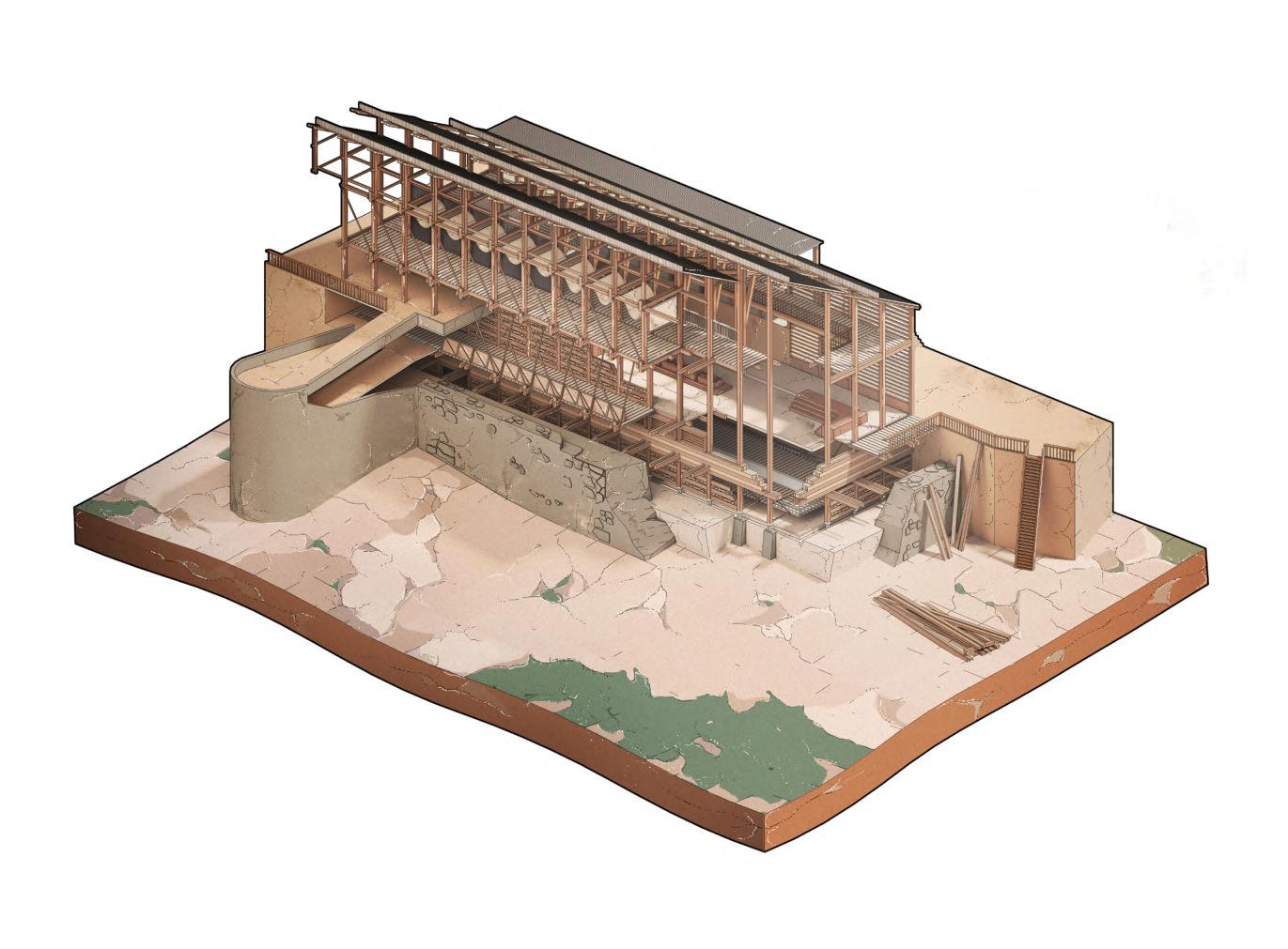
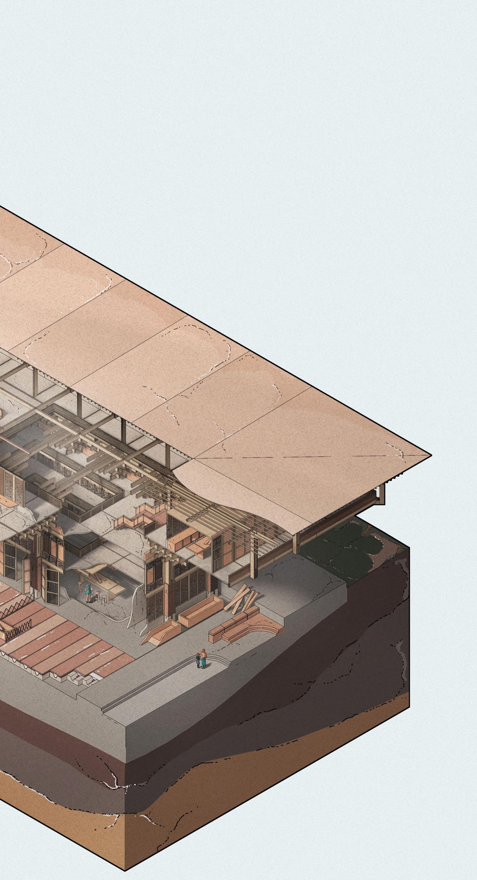
86
Primary Secondary Tertiary Infill
Carpentry
Previous Iteration Deodar wood beams 2 2 1 4 3 4
4.10D
Carpentry Workshop Site Plan
Workshop
Figure
CHAPTER 4 _ LHUENTSE SCHOOL OF CRAFTS BARC0174 _ AAD1
Figure 4.10C
Roof Construction
Himalayan Pine finished Ceiling Insulation Infill
Key Section
Primary Glulam Rafters
Moisture and Water Membrane
ROOF BUILD UP
The use of triangular slate roof tiles references the use of Himalayan roof construction identified in Kath Khuni dwellings. The building adapts the system with additional infill layers to create stronger thermal integrity, while the inward facing pitch allows for cooler ventilation and the absorption of heat during summer. The roof tiles may also be assembled incrementally by local labour, in a participatory group exercise.
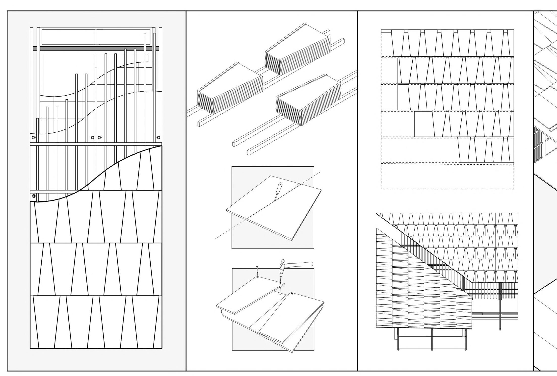
PROPOSED ROOF TILE ASSEMBLY
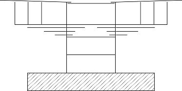

A. Typical build up with infill layers.
B. Slate tiles are cut into triangular shapes and nailed at a pitch with an overhang to allow snow runoff.
C. The slate tiles are fixed with an overhanging eave.
D. The tiles are assembled by hand using local labour.
Secondary Roof Rafters
Timber Roof Purlins
Slate Roof Tiles
Thermal Mass
4.11
Section
Heat
ABCD
Release
Figure 4.11A
Roof Hierarchy
Key Roof Structural Principles
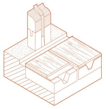
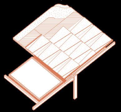
ROOF PITCH
The slight angle of the roof allows for water redirection and reuse, and when snowing, the tiles can catch the condensing snow, and channel it into ground floor drainage.
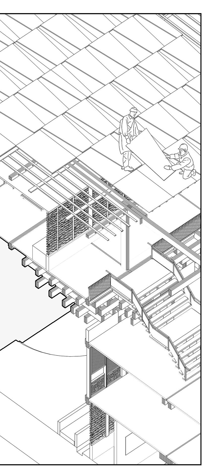
SERVICE CEILING
Due to the extreme climate of the site, the building requires a concealed arrangement of service pipes, exhausts and utilities. An extra build up of dry stone/timber creates an additional thermal barrier to the exterior whilst a cavity tray similar to the Halley VI Research Station directs servicing overhead. This intends to create a safe work environment.
Branching outwards from the central courtyard, the inward facing roofs are differentiated by four different heights and decreasing sizes, creating a clear visual hierarchy.

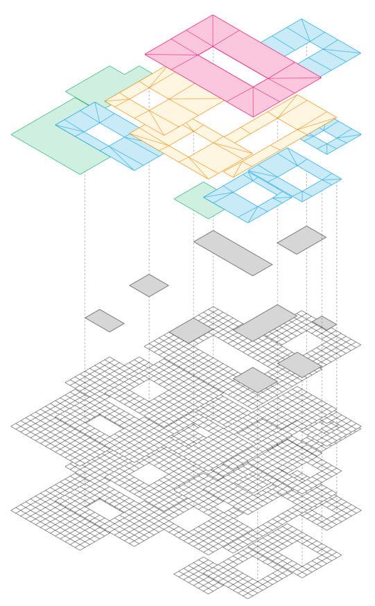
GUTTER & DRAINAGE CHANNEL
Rainwater is collected via a gutter on the eave of the roof, which is directed downwards via gaps in the vertical glulam columns towards a channel on the ground floor (shown below left). This water can then be distributed across the ground floor of the building via the integrated service pipes of the dry dock system (for use as greywater in toilets and nearby planting).
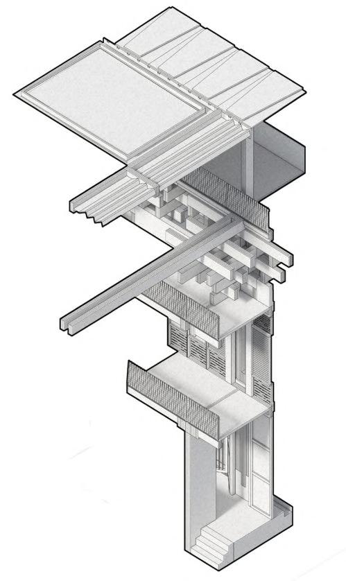
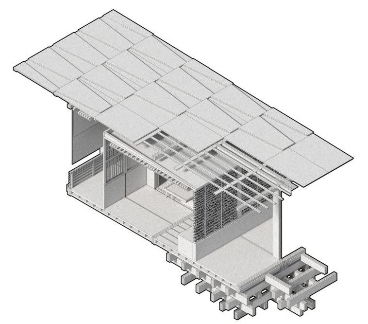
ROOFLIGHTS
A combination of rooflight windows and shutters allow the internal control of solar gain and natural ventilation.
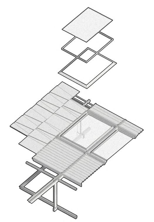
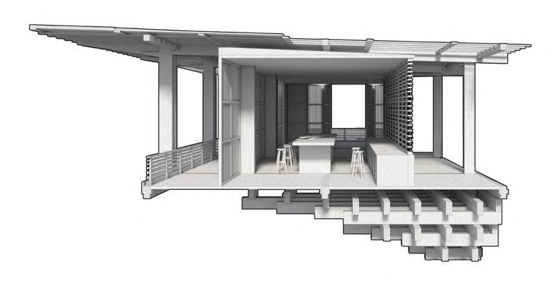
88
Flashing Key Junction Water Redistribution Channel A. Roof Tile B. Moisture barrier C. Insulation D. Integrated gutter outlet E. Flashing to direct water runoff Metal Flashing around window Shutters A. Glulam column with centrally capped concrete footing to direct water runoff B. Water redistribution channel C. Concrete dock with accessible underground servicing D. Poplar decking A A B C D D E B C CHAPTER 4 _ LHUENTSE SCHOOL OF CRAFTS BARC0174 _ AAD1
Construction Sequence
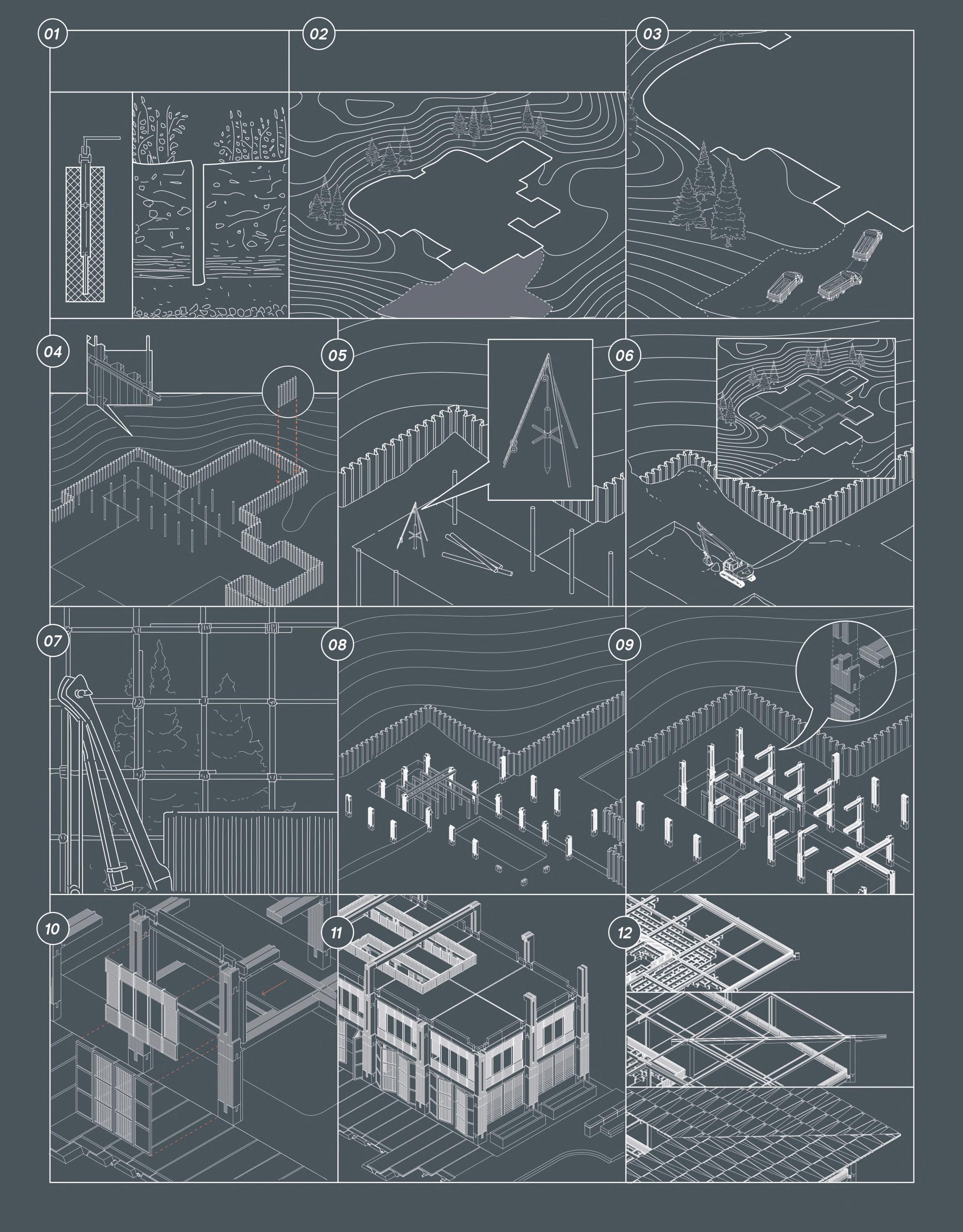
Section 4.12 89
Site Testing - Site studied and geology information obtained for preparation of foundation construction. Soil sampled using Vane Sheer Testing (below left). Soil tested in local laboratory. Site Boundary - Site perimeter established prior to excavation. Due to the site’s high altitude, an extended boundary for the unloading and delivery of equipment and materials, as well as the temporary housing of staff is created at the entrance of the site. Sheet Piles - The use of heli-piles are initially used to mark the edge of the site boundary, and later to provide support to drive the sheet piles into the earth. Delivery of Materials - Due to the lack of nearby road infrastructure, an extended road network creates easier access for the on-site delivery of materials and equipment. The delivery point also includes designated zones for parking and the repair of vehicles. Site bore-hole for sampling and testing Delivery Unloading Point Site Perimeter Guide beam supported by heli-piles Timber Pile FoundationTimber tripod pulley system is delivered and assembled on site, after which a manual auger is used to assess the site’s ground conditions, and the building foundation process can start. Assembly of construction equipment - On site infrastructure assembled including cranes, bamboo scaffolding and demountable accommodation for staff. Dry Stone/Timber Infill - Timber louvred wall panels with dry stone and rubble infill alongside louvred doors form the building’s facade. Dry Dock - The construction of the ground floor’s dry dock with cast insitu concrete creates a cavity for the installation of underground service pipes. Precast Floor Slabs - Standardised precast concrete floor slabs are slotted and secured into place between glulam beams for easy assembly. Roof Construction A. Stacked cantilevered timber members assembled. B. Roof beams and columns constructed. C. Roof purlins and internal roof build up completed prior to assembly of slate roof tiles. Ground Floor columns assembled - The composite vertical glulam members with a concrete footing form the primary structure of the building, and support the assembly of upper storeys. First floor beams and columns assembled - First floor glulam beams and columns are slotted into connections with the addition of dowel connections and timber reinforcement for support. Excavation - The process of earth removal de-waters and solidifies the earth, and is used to fill areas of the site, adopting a cut and fill approach. Machinery is also minimized to reduce pollution and noise disturbance. COMPLETED SITE CUT AND FILL A. B. C.
Figure
4.12A
Figure 4.12B
Figure 4.12D
Figure 4.12C
30mm Deodar wood cladding Damp proof membrane 300mm sheeps wool insulation & Timber studwork 15mm Himalayan Pine cladding
Dorm Detail Study
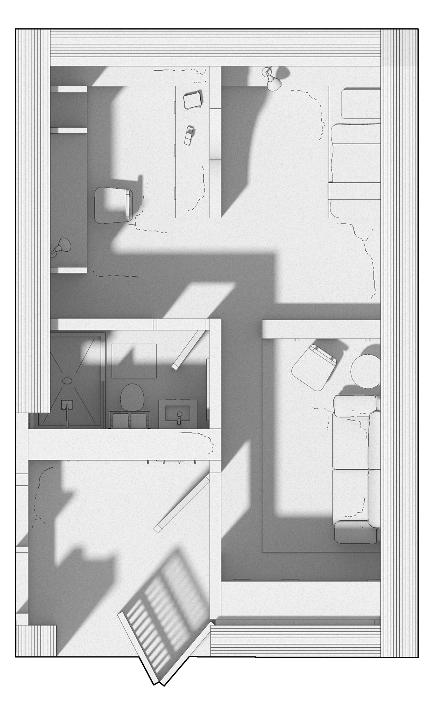
DORM STUDY SPACE
The left drawing displays an extract of the workspace in one of the dorm rooms, used by one member of staff. Although the rooms vary in size, larger provision is made on the upper storey for staff members, to accommodate their personal belongings and create privacy.
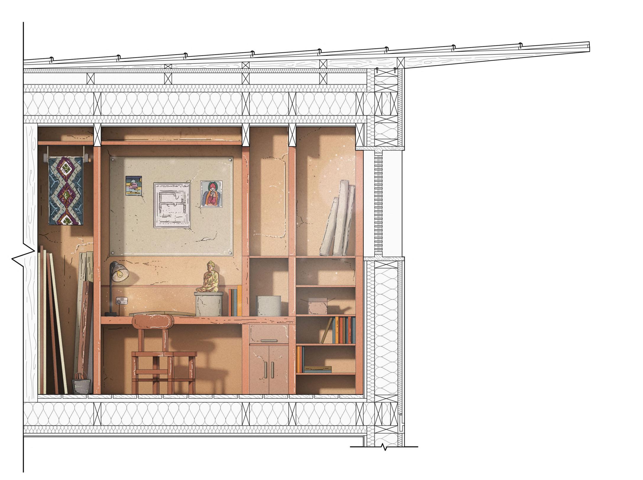
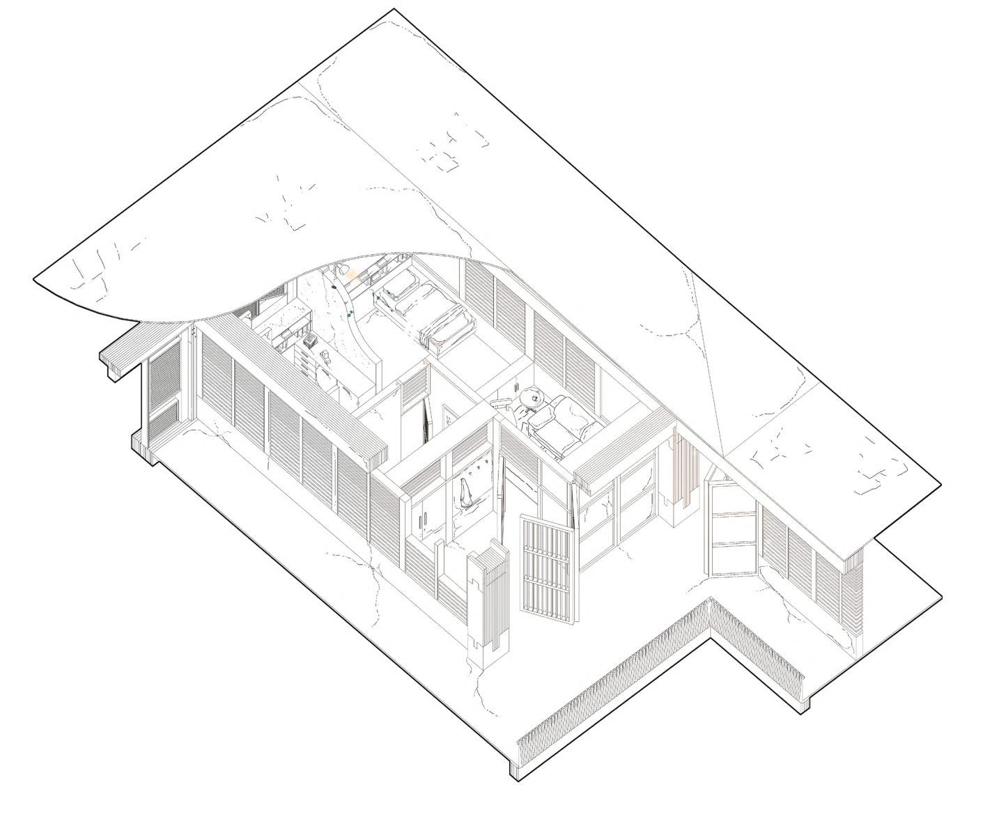
Study Space Sectional Detail
Slate roof tiles pinned with nails
Himalayan Pine soffit
Deodar wood vertical cladding
Himalayan Pine louvre window opening
300mm rigid foam sheeps wool
insulation
Zinc flashing drainage
150mm x 100mm / 300mm x 100mm
Deodar wood roof purlins
300mm x 100mm Deodar wood floor
beams
Internal Poplar plank floor decking
1-Bed Staff Dorm Room
Section 4.13 90
Outside Inside
1 1 2 2 3 3 4 4 5 5 6 6 7 7 8 8 9 9 A B D E C A Overall Dormitory Roof Plan Detail Section A Typical Wall Build up B-B BB Scale 1:30 @ A3 A. Study Space B. Bedroom C. Bathroom D. Living Room E. Foyer, Storage & Cloakroom Figure 4.13A
First Floor Plan
Section 4.14
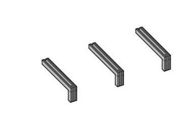
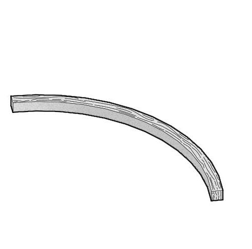
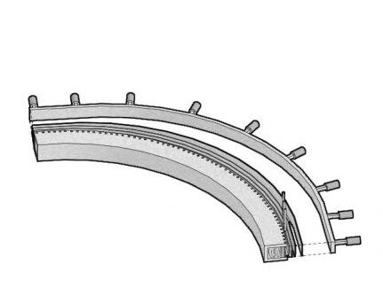
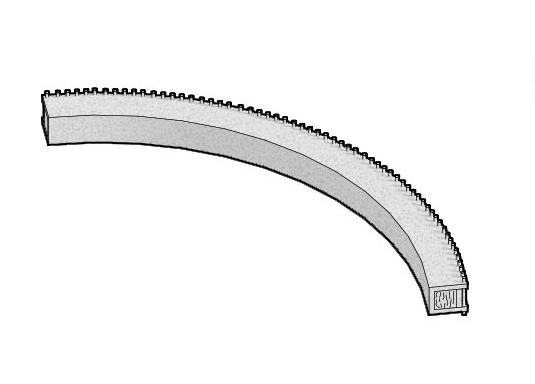


Central Courtyard Detail Study
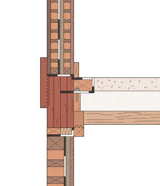
CENTRAL COURTYARD:
EXTERNAL
The long section below explores the combination of workspaces that filter into the main central courtyard, blurring the outdoor and indoor environments. Each of the volumes delineate a plinth, with upper storeys extending and integrating into one another to provide both shading for lower spaces and a frame for the central Buddha sculpture, which behaves as a symbol of knowledge. KEY
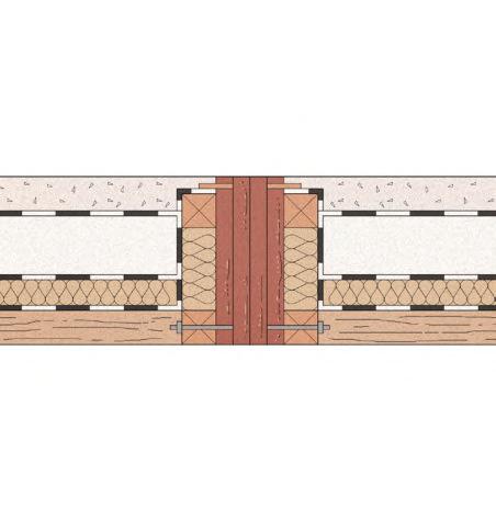
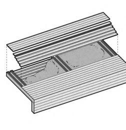
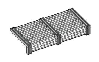
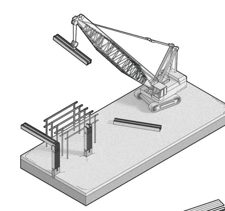
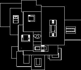
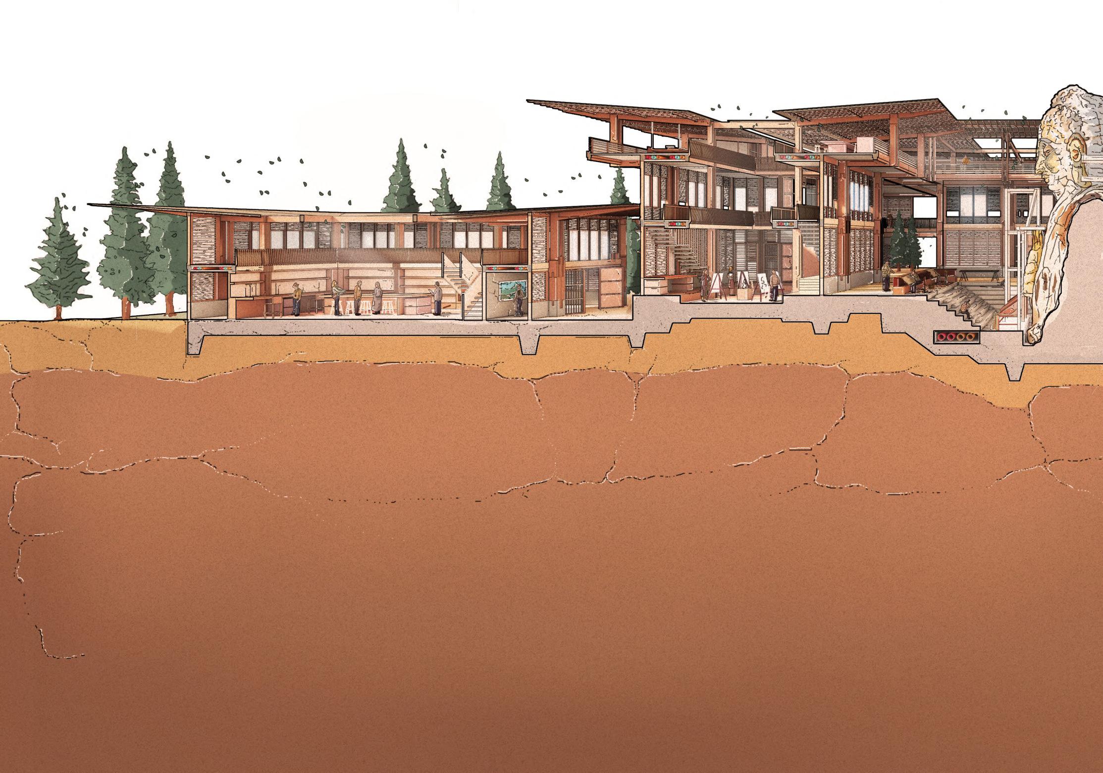
WORKSPACE
EXHIBITION
AND
SPACE
SECURITY / STAFF ROOMPAINT WORKSHOPCENTRAL COURTYARD & OUTDOOR Assembly Process Diagrams A - C explore the assembly of both bespoke timber glulam members through to in-situ cast concrete floor slabs. i. Timber elements assembled ii. Rebar is used to reinforce the timber members iii. Concrete is poured into the cavities produc by the rebar and timber members, which is clad using formwork on both the inner and layers, creating a strong floor build up. Hydraulic Press Top Tray Bamboo Fibres Pins Mould Curved members used in the scaffolding and the building are cold pressed using moulds to create different beams. Structural Concept The section references the Vierendeel Truss and Kuma’s Yusuhara Wooden Bridge Museum to consolidate east and south Asian influences in a hybrid structural expression. Vierendeel TrussCantilevered Stacking System Composite Truss - Cantilevered Glulam Stack A. C. Pre-Fabricated Timber Craning Formwork and Concrete AB C A B 1. External Timber Layer 2. Deodar Beams 3. Damp Proof Membrane 4. Thermal Wool Insulation 5. Himalayan Pine Wall Section 6. Stainless Steel Bolted Connection 7. Primary Glulam Member 8. Deodar Beam Section 2 4 9 1011 371112 41415913 1314 3 5 6 7 8 1 External Wall to Mezzanine Floor Detail Junction Mezzanine Floor Detail Junction A. B. 9. Fibre Wool Insulation 10. Skirting Board 11. Precast Concrete Slab 12. Deodar Floor Joist 13. Himalayan Pine Finish 14. Ventilation Cavity 15. Bolted Connection
CONSTRUCTION DETAILS
Figure 4.14A Figure
Using timber and bamboo, the central Buddha sculpture is constructed alongside a simple scaffolding system to accommodate all user groups.
Figures 1 to 4 illustrate the temporary mechanisms employed in the scaffolding for the central Buddha sculpture. Due to its scale, the scaffolding aims to combine a timber support system with bamboo to ensure the sculpture remains rigid and upright during its construction. A series of bespoke features ensure the safety of staff and students during its construction, as well as an easy assembly and disassembly process. A suspension system allows easier movement of tools and machinery during construction.
Scaffolding Strategy
Maintenance Walkway - A timber decked walkway accommodates maintenance and head clearance.
Ladders - Ladders can be reconfigured for alternative uses for repair and access.
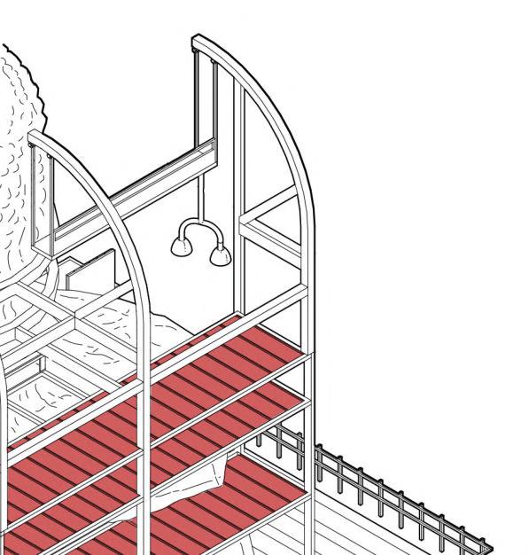
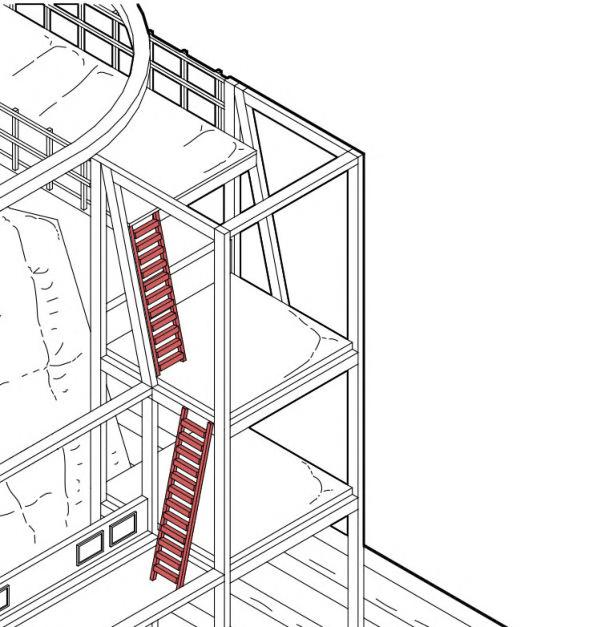
Pulley System - The pulleys of the suspension system allow the safe lowering of tools and machinery.
Extendable Seating - To create a more comfortable work space, seats can be extended and retracted.
CENTRAL COURTYARD SCULPTURE MAINTENANCE
OUTDOOR WORKSHOPTEXTILES WORKSHOPTEXTILES OUTDOOR WORKSHOP
A. Standard Vertical Members - Similar to a Vierendeel Truss, vertical members are positioned where forces apply.
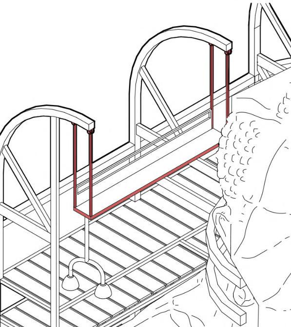


B. Adaptation - A cut and fill approach adapts member height.
C. Layering - Additional storeys create lengthened members.
1. Floor to ceiling height established
2. Overhead services implemented
3. Forces and moment connections
4. Overhang creates shading device
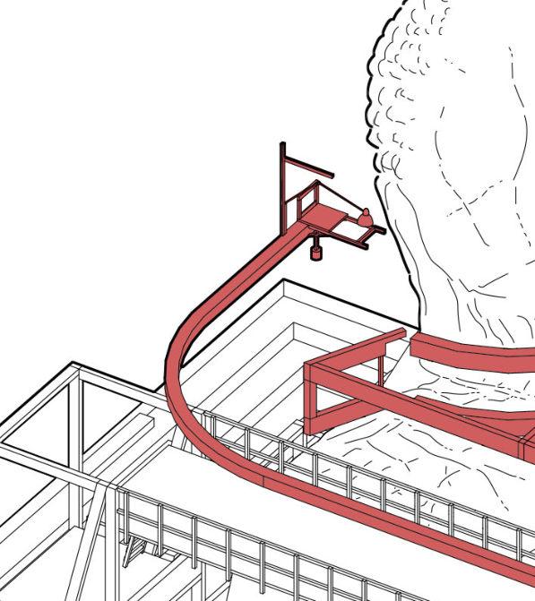
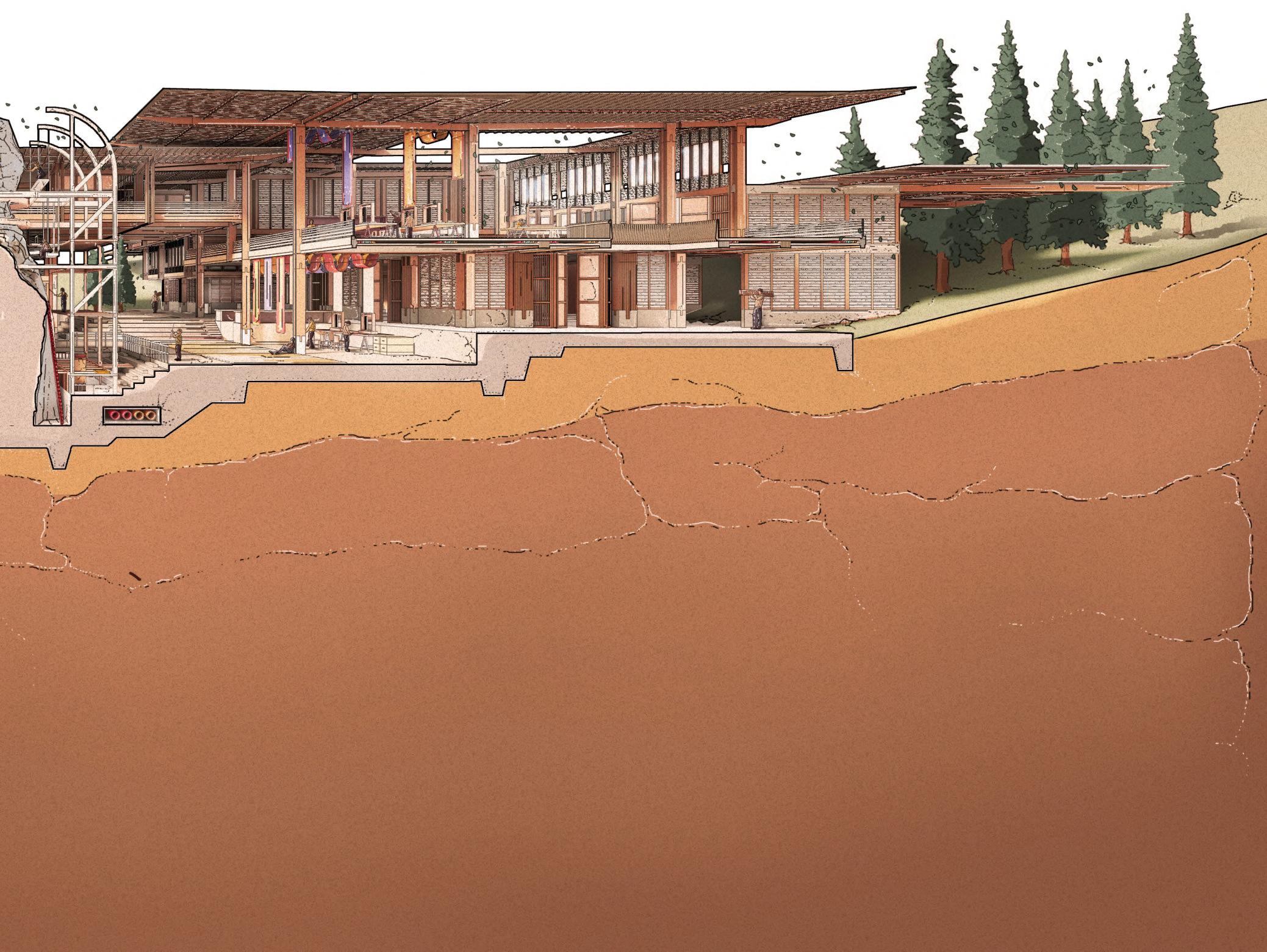
92
STRATEGY
assembly cast produced later outer
1 3 2 1 3 4 2 4 Figure 4.14B
B.
Figure 4.14C
CHAPTER 4 _ LHUENTSE SCHOOL OF CRAFTS BARC0174 _ AAD1
Figure 4.14D
Section 4.15
Mechanisms of the Carpentry Workshop
HEALTH AND SAFETY
Due to the use of both heavy and light machinery, ensuring the health and safety of both students and staff is very important. In accordance with local guidance, the carpentry workshop aims to provide safe equipment, storage and handling of machinery, and a flexible working environment, with adherence to the requirements of certain tool and power resources.
Workshop Machinery
Potential hazards include: Flying work pieces Traps in belt drive Sparks in metal work Burns
FIRE SAFETY & CONTROL
The use of linings, and the identification of unprotected wall areas allows the control of fire spread in the workshop.
PHASING
01. Excavation
Alongside the use of poured concrete, the excavation process uses heli-piles with “caps” to create less impact on the site’s soil.
02.
Cut and Fill
The removal of earth aims to roughly match the amount needed for the “fill”, to help minimize the amount of construction labour.

03. Primary Structure
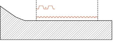

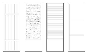
The assembly of vertical glulam members slotted in concrete studs allows the installation of plumbing, wiring & services within cavities.
INTERNAL OPENINGS
Different perforations of dry stone in combination with concrete and timber create varied internal conditions.
Composite Truss
Cantilever - A standard member uses tension on the top surface and compression on the bottom.
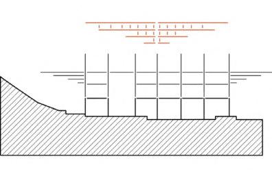
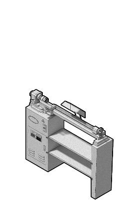
Truss - A Vierendeel truss does the opposite, with tension on the bottom and compression on the top.
Combined System - The use of an adapted Vierendeel truss with a cantilevered edge creates a compressive upper layer combined with a tensile bottom layer, to help consolidate both structural systems.
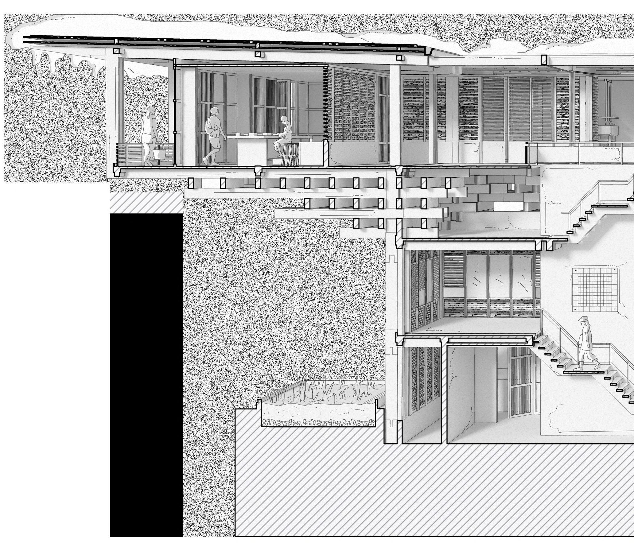
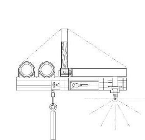
Existing Composite Slab - The composite truss adapts the partially composite (top two), and fully composite slab (bottom two).
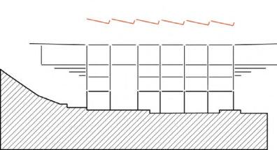
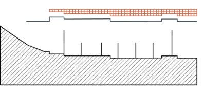
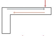
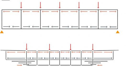
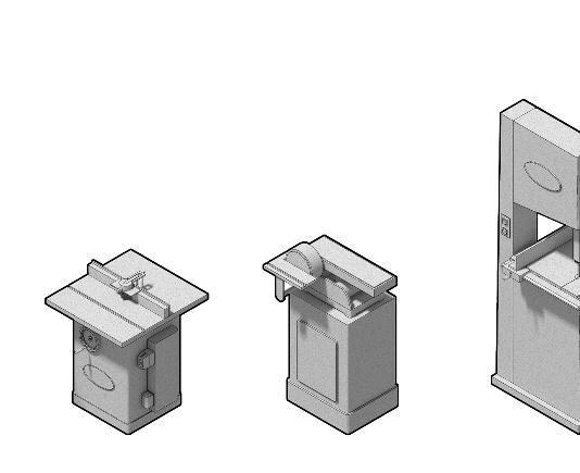
A B C
A. B. C. Tension Par Par Positiv Positiv Compression
04. Roof Tiles
Slate roof tiles are installed at angles to allow for snow runoff that can later be reused and distributed across the building via drainage.
Mechanical Extract
Table SawLatheDisc sanderBandsaw
Sprinkler System
01.02.03.04.
to adjust machinery
are adjustable to control ventilation
High level plugs used to prevent tripping Manual controls
Exhausts
Figure 4.15A
Figure 4.15B
Figure 4.15C
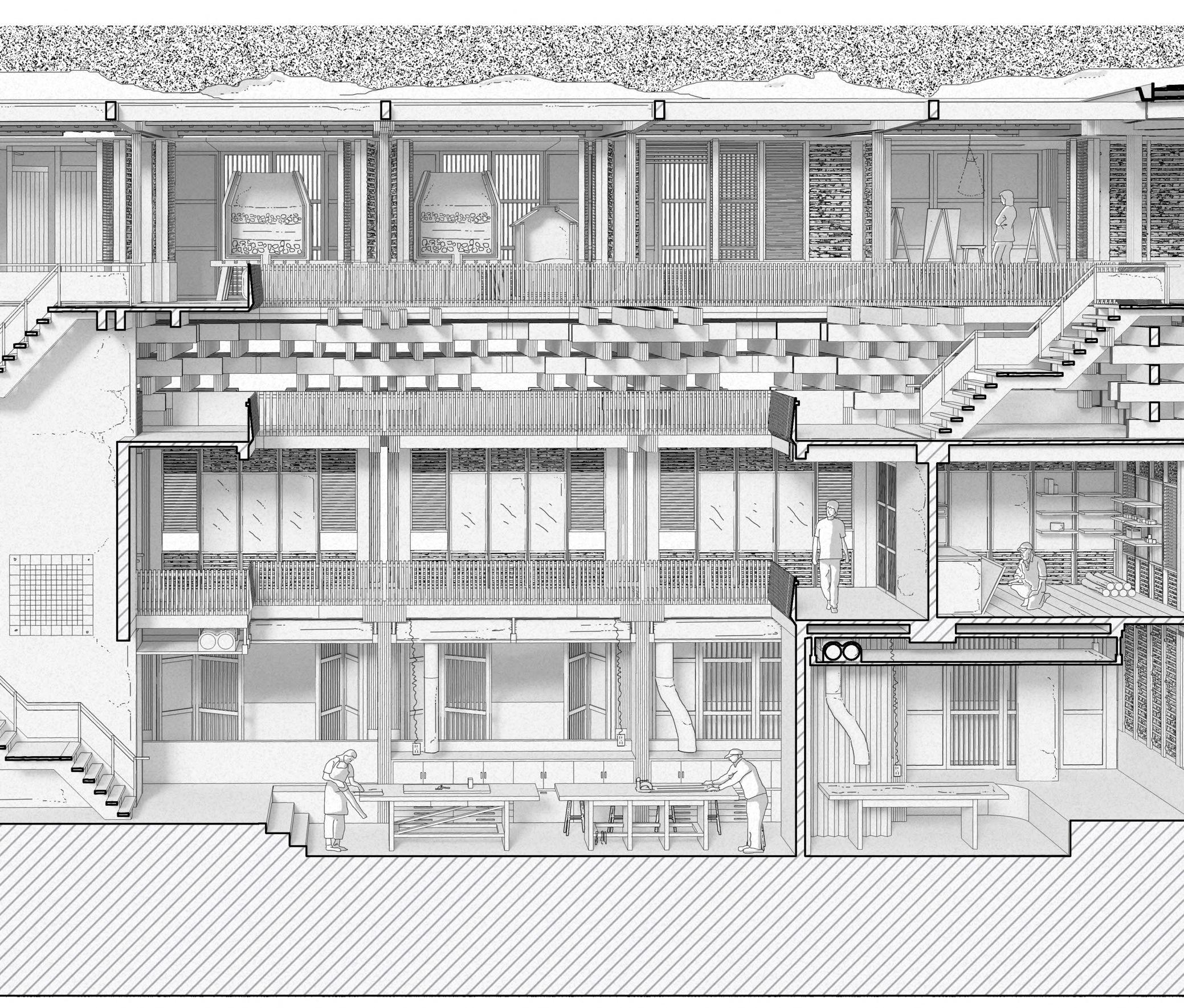
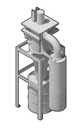
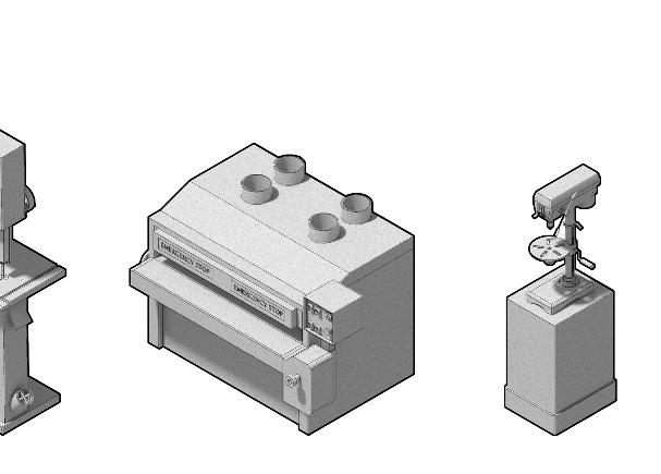
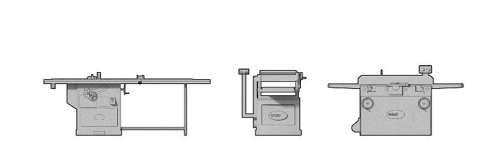
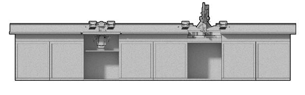
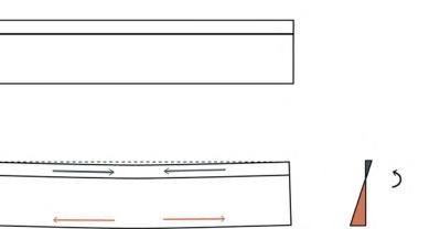
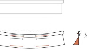
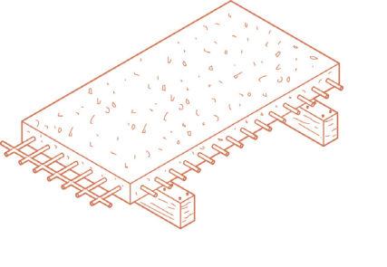
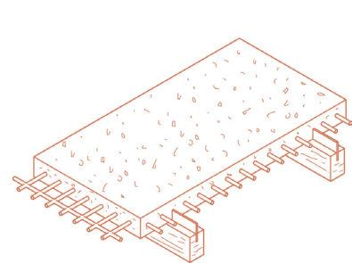
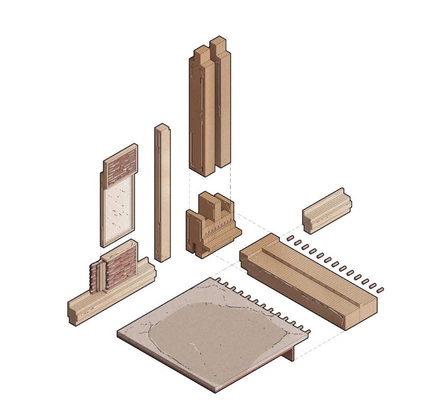
94 Tension Tension Parallel to Beam Parallel to Beam Positive Bending Moment Positive Bending Moment Compression Existing Timber/ Concrete Composite Existing Timber/ Concrete Composite Primary Timber Dowel Connections Timber Reinforcement Timber Column In-situ Concrete Slab Waterproof Membrane Rigid Insulation Rainscreen GRC Cladding Dry Stone Infill Compression M M Material Hybrid Thickness planerPillar DrillSandblaster Thickness Planer & Table Saws 05.06.07.08. Additional partition sheets can be used to stick notes on walls Emergency buttons are implemented to limit hazards to usersOperators adjustable 1 2 3 6 7 8 9 4 5 1 2 3 4 5 6 7 8 9 Steel & Dowel Connection Shear Connector - Steel Mesh Concrete Stair Core Extract & Intake Suspended charging points
Figure 4.15F
Figure 4.15G
Figure 4.15E
CHAPTER 4 _ LHUENTSE SCHOOL OF CRAFTS BARC0174 _ AAD1
Figure 4.15D
Lhuentse Climate Data
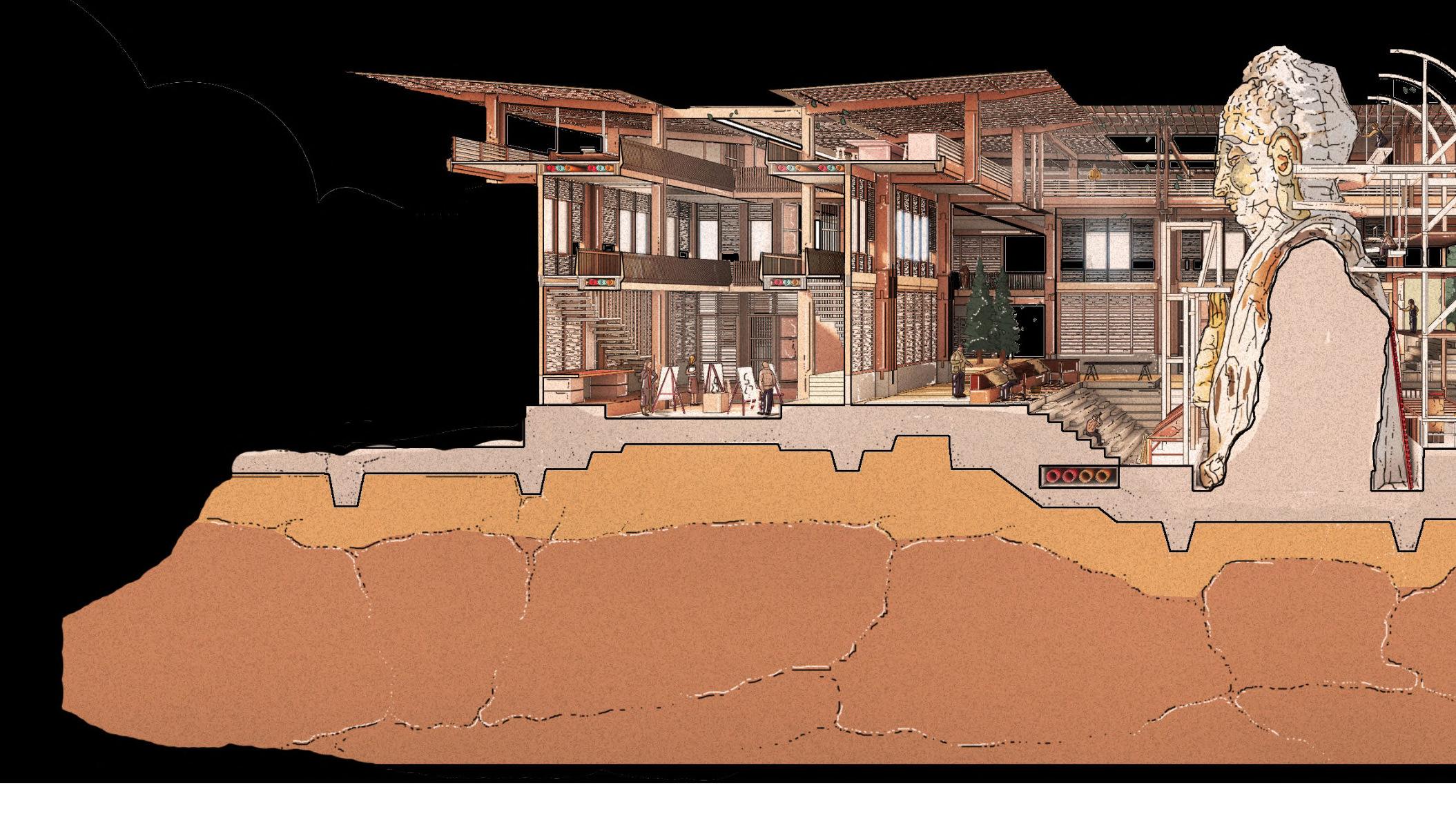
The charts show a meteorological simulation of Lhuentse’s weather. The data shows that high levels of precipitation, particularly in July, follow seasonal effects such as the monsoon climate in India. High temperatures reach above 15oC, and correlate with the monsoon season, as suggested in the graphs. The wind speed also reaches high levels due to the Tibetan Plateau, where the monsoon season causes strong winds between December to April, and calmer winds between June and October.
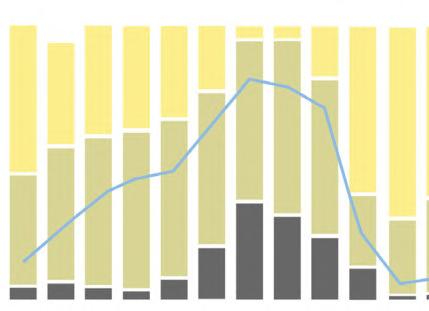
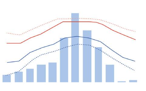
Average Temperatures & PrecipitationCloudy, Sunny & Precipitation Days J J F F M M A A M M J J J J A A S S O O N N D -20 C Precipitation SunnyPartly cloudyOvercastPrecipitation days Cold nightsMean daily maximum Hot days Mean daily minimum 0 days 0 mm -10 C 5 days 25 mm 0 C 10 days 50 mm 10 C 15 days 75 mm 20 C 20 days 100 mm 30 C 25 days 30 days 125 mm 150 mm
Figure 5.00A


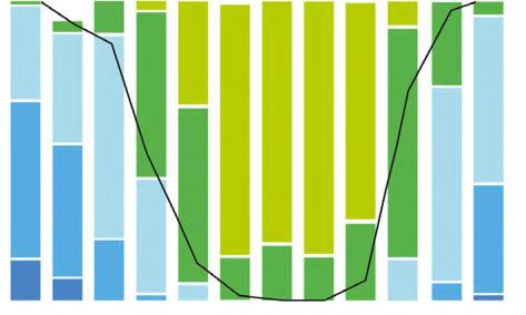
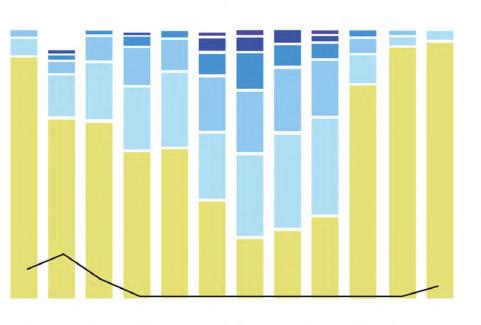
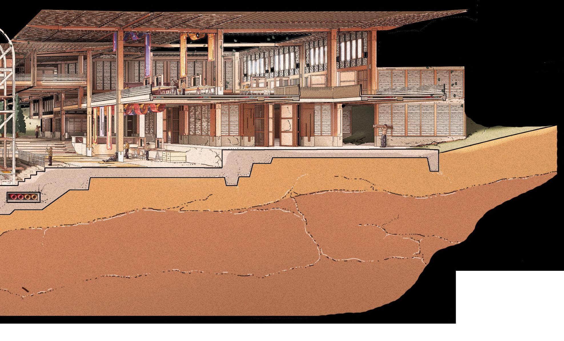
ENVIRONMENTAL STRATEGY 05 Chapter 96 Maximum TemperaturesPrecipitation AmountsWind Speed J J J F F F M M M A A A M M M J J J J J J A A A S S S O O O N N N D D D D > 15 C 50-100mm 0>0>3>7>12>17>24>31>38 mph Dry days 20-50mm Snow days 10-20mm5-10mm 2-5mm < 2mm > 10 C> 5 C> 0 C< 0 C Frost days 0 days 0 days 0 days 5 days 5 days 5 days 10 days 10 days 10 days 15 days 15 days 15 days 20 days 20 days 20 days 25 days 25 days 25 days 30 days 30 days 30 days BARC0174 _ AAD1LHUENTSE SCHOOL OF CRAFTS
5.01 _ Overall Environmental Strategy
Carpentry Workshop

HARNESSING RAINWATER AND SNOW
The abundance of snow and rainfall in Lhuentse’s local climate creates an opportunity to harness the weather to reduce thermal costs. The inward facing roof form harnesses solar gain and prevailing wind driven precipitation, collecting rainwater via fixed slate tiles and a harvesting system. The deep dry stone/timber walls create a thick cavity and thermal barrier, behaving as an envelope to the exterior.
Slate Roof Tiles
Assembled manually, slate tiles create a thermal barrier to the building, as well as redirecting water and snow runoff to the rainwater harvesting tanks.
Carpentry Workshop Roof Plan Rainfall Direction
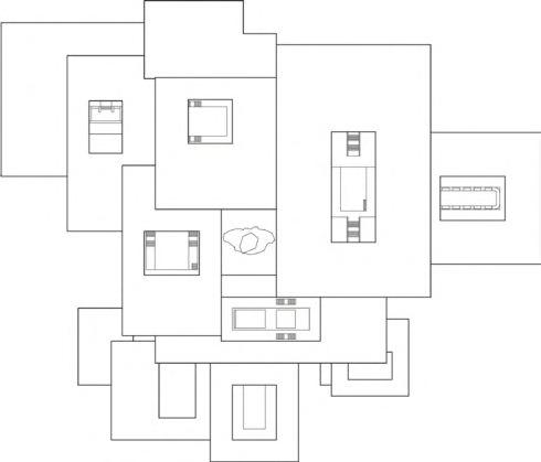
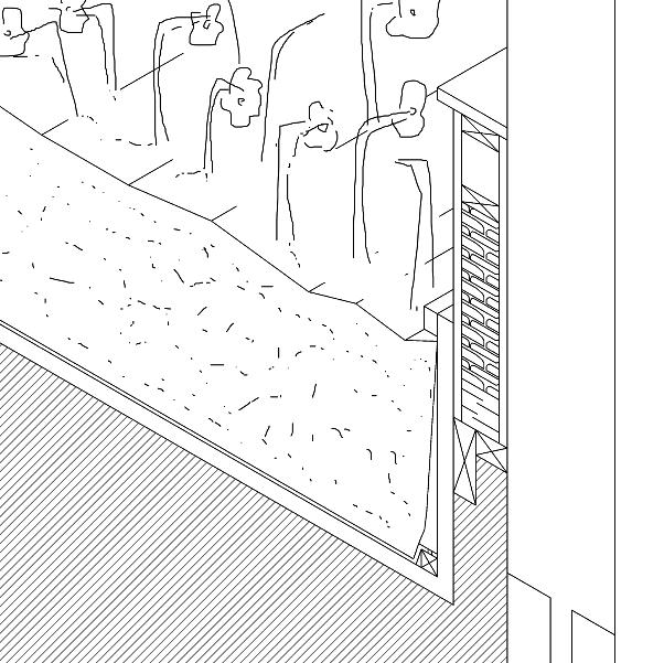
The inward facing roof volumes each redirect water to a harvesting tank, whilst also allowing users to open rooflights.
Rainwater Collection
The tile and gradient of the roof pitch helps to move water at a consistent speed and quantity. The overlapping, triangulated slate tiles create cavities in which snow can collect to prevent its excessive build up.
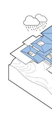
The pixelated roof and voids increase solar exposure to workshop spaces.
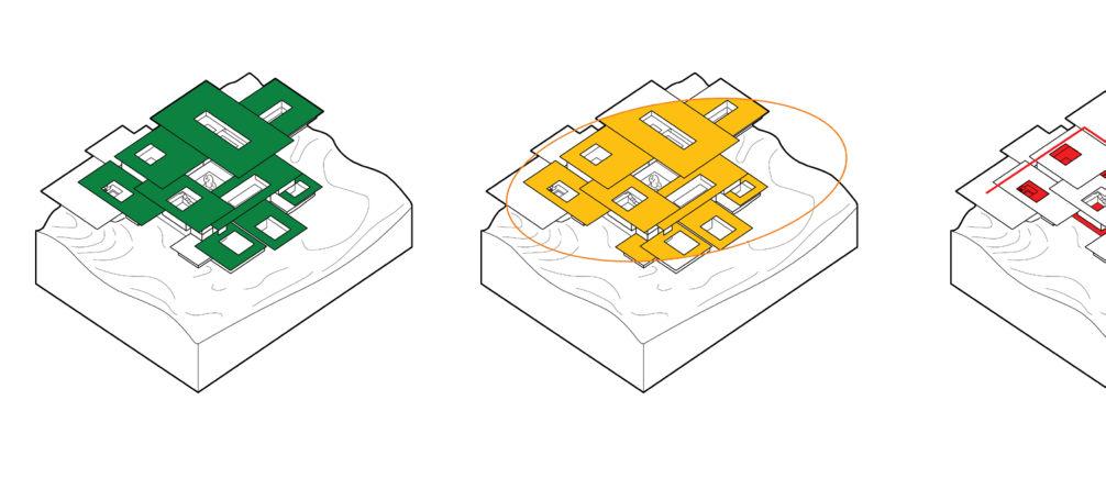
The foundations and reinforced concrete ground floor create a flood defence to each volume.
Snow/rainwater is dispensed into rainwater harvesting tanks for distribution around building. Inward facing roof pitch channels rainwater and snow into gutter which is filtered into rainwater harvesting tank for redistribution across building. Glulam columns with central channels direct rainwater into outdoor plant beds.
Photovoltaic Panels
Some areas of the roof are fixed with PV panels, orientated at different angles allowing the panels to capture sunlight at different times of the day, creating a self-driven and renewable energy approach.
Native Planting Treatment
The outflow of wastewater is used to treat native Bhutanese plants including blue poppies (endangered species) and
Bacteria helps translate the soil into compost which is used to nourish the plants.

Movement of Hot Water
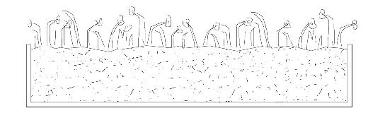
Located in a different region of the same cross section neighbouring the plant bed, the detail below shows the structural build up required for the conservation of water. Rainwater and greywater from the plant bed is redirected to the ground source heat pump which is then pumped across the campus. The water temperature is regulated and then circulates hot air across the workshop through overhead vents during winter.
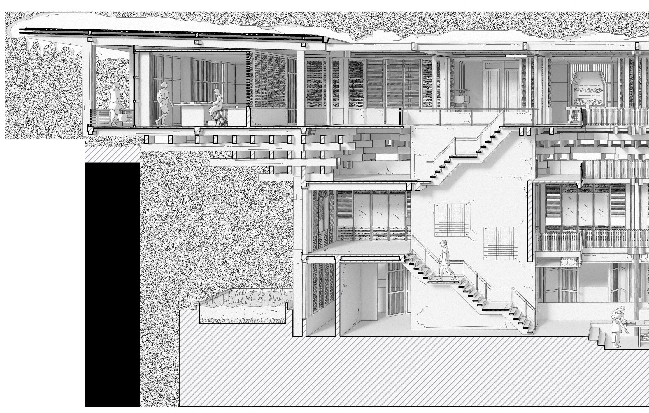
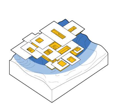
Building Life Cycle
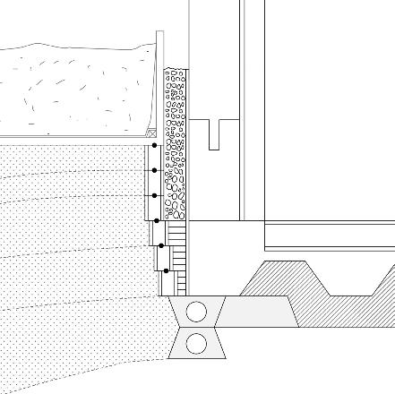
MaterialGlulam Primary Structure Ground floor slabs and foundations Upper floor slabs and stair cor 111.92 0.350.10.1 Yes Yes, when crushedYes, when crushed In-situ concretePrecast concr Use Embodied Energy per kg Embodied Carbon per kg Recyclable Material to Factory Waste Material
Wind Driven Rain Solar Gain Flood Prevention Thermal Strategy Rainwater Collection
Key Detail 1. Primary glulam column 2. Load bearing concrete plinth foundation 3. Water proof membrane and cavity
Concrete floor slab and poplar decking
Rubble infill
Packed earth blocks
Stacked concrete blocks 8. Concrete trench with service cavities 9. Embedded service pipes to ground source heat pumpcold water taken to pump and returned as hot water. Hot water Cold water
4.
5.
6.
7.
Gutter WASTE TREATMENT TANK Hot water is pumped to shower and toilet facilities Greywater pumped to outdoors, then redistributed back to toilet. Stale air is from workshop through stack effect via rooflights Greywater channelled to outdoor native plant bed. Blue Poppies & Orchids Waterproof Membrane Wastewater Inflow Wastewater Inflow Outflow Outflow Soil 6. 5. 2. 3. 4. 8.9. 1. 7. The construction process seeks to minimize transportation, manufactur materials, to help extend the building’s
Figure 5.01D
Figure 5.01A
Figure 5.01C
Figure 5.01F
Figure 5.01E
Rainwater Harvesting
Using a combination of (1) dry rubble, (2) silt and soil, and (3) fine stones, the rainwater tanks use layers of locally sourced waste material and topsoil to act as filters. The portable water tank also uses a filter to treat rainwater and snow. This lowtech approach aims to reference historic Bhutanese and Himalayan dwellings to prevent the overuse of high-tech water management solutions. The system capitalises on the local climate and the prevalence of the monsoon season to create a sustainable water harvesting strategy.
Biomass Stove and Boiler

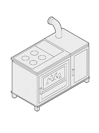
Wastewood from the workshop is used as fuel for the biomass stove. The heat generated is used in the heat exchanger and transferred in the exhausts.
Wastewater Treatment System
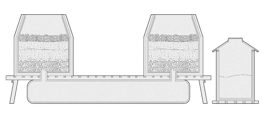
The building aims to adopt a self-driven and renewable energy solution using low-tech and user operated technology. This aims to reduce carbon emissions and excessive energy use by generating energy for building occupants only.
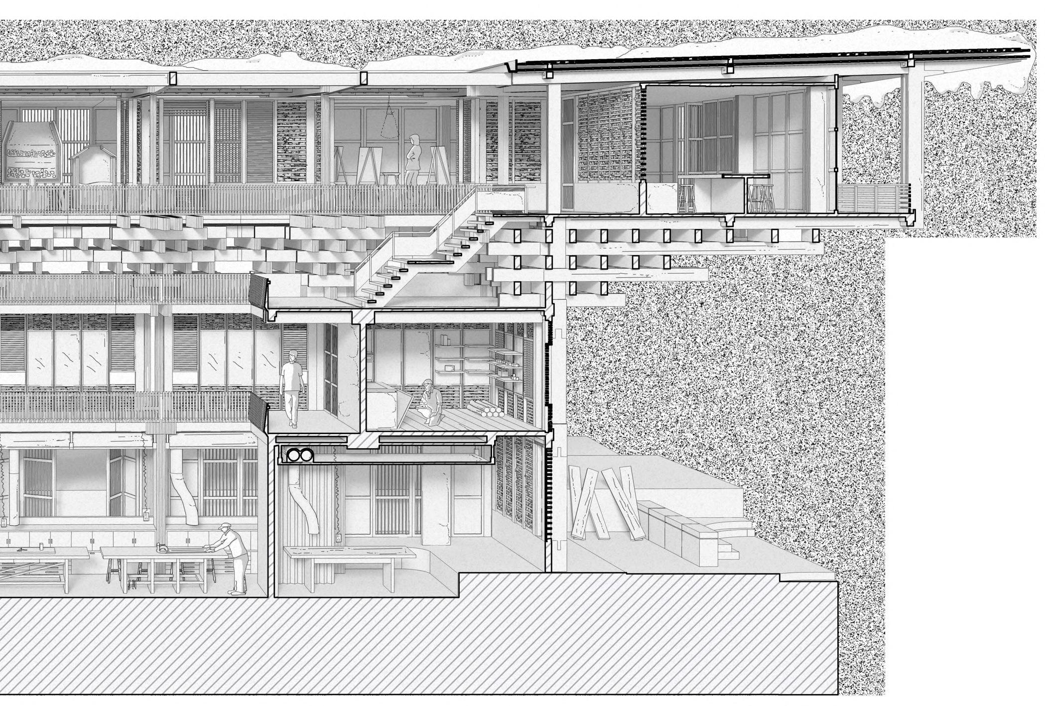
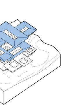
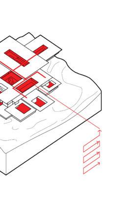
Locally harvested food can be prepared and eaten communally, both indoors and outdoors.
Users become directly aware of their use and impact on the surrounding environment. This extends to the use of a small scale wastewater aerobic treatment unit (shown below) which treats wastewater efficiently without the need for conventional septic tanks.
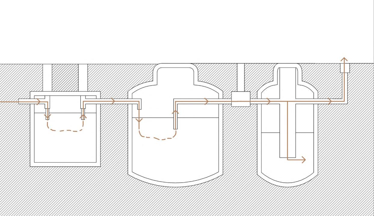
98
Food
slabs cores Secondary & tertiary wall infill Carpentry Workshop glulam weight (using deodar wood) = 550 kg/m3 Beams and columns = 25.92 m3 Roof rafters and purlins = 12.96m3 Total = 21 384 kg Carpentry Workshop concrete weight = 2400 kg/m3 Ground floor slabs = 162 m3 Upper floor slabs = 570 m3 Total = 1 756 800 kg Total CO2 = 7484.4 kg CO2 Total energy = 235 224 Mj Total CO2 = 175 680 kg CO2 Total energy = 3 513 600 Mj 0.1 0.079 crushedYes, as aggregate concreteDry Stone Rainwater Tank Secondary Tank Portable Water Tank Fully enclosed thermal envelope
1. 2. 3.
Pitched roofs increase water retention and its movement. PV Panels absorb energy from sunlight, which provides electricity source for workshop through battery HEAT EXCHANGE Lighting uses electricity provided by PV panels Retractable rigid curtain reduces noise pollution in workshop Dry stone and rubble infill in external wall preserves thermal mass, retaining heat. Workshop uses electricity for tools via deployable plug sockets is removed orkshop stack openable Single Compartment Waste Tank Aerobic Treatment Tank Pump Tank Chlorinator Recycling Material Waste Building Components eeks to limit offsite construction manufacture and wastage of building’s life cycle.
5.01B
Figure
Figure 5.01I
Figure 5.01H
CHAPTER 5 _ ENVIRONMENTAL STRATEGY BARC0174 _ AAD1
Figure 5.01G
Energy Use
Energy Systems Overview
Lhuentse’s extreme climate and high altitude creates an opportunity to harvest rainwater and snow to provide renewable sources of energy. Existing hydroelectric dams nearby Lhuentse provide a reservoir where water can be stored during the night when solar power is no longer a viable source of energy. This intends to create a loop where PV panels on the roof collect sunlight, generating energy. This energy pumps water into the building from a reservoir and is released and returned to the reservoir during the evening, creating a renewable and cyclical process.
Savings by Design & Management
The largest users of power in the building come from workshop machinery, kitchen equipment and electric tools. Turning off machinery when not in use will help reduce energy demand in the building. The building also aims to supply nearby homes with energy in a shift towards a decentralised approach, free from the country’s national grid and the uncertainty it creates due to political changes in policy and regulation.
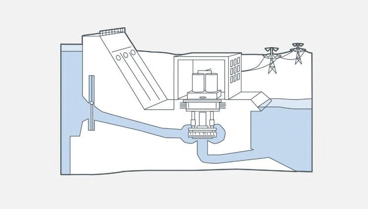
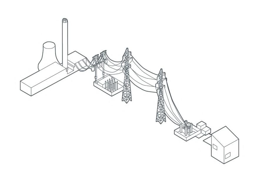
Using Local Resources

Annual rainfall in Bhutan is 1916 mm per year, while aggregating approximately 431mm of snow per month. Due to the high altitude, the site also experiences high winds.
Energy Challenges
Grid access is limited, encouraging the move towards a decentralised network. Temperatures remain low throughout the year, sometimes falling to -0.5oC.


Energy Solutions
Rooftop PV panels maximise solar gain; stale air is removed naturally through stack effect; need for artificial lighting is limited due to rooftop and window openings.
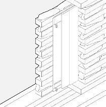
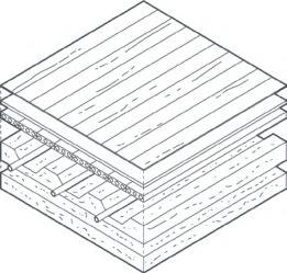
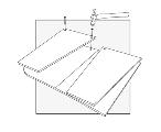
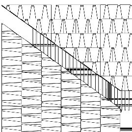
Occupation Energy Use
Average Bhutan household energy use is 12.3 kWh per day (4 people). Due to the absence of high energy machinery like electric heaters and dishwashers, the figure is estimated at: 70% x 12.3 kWh x (15/4) = 32.29 kWh / day
The building seeks to generate its own energy independent of the country’s national grid, and through the use of voltage, input energy into nearby households in Lhuentse.
Hydroelectric Power in Bhutan
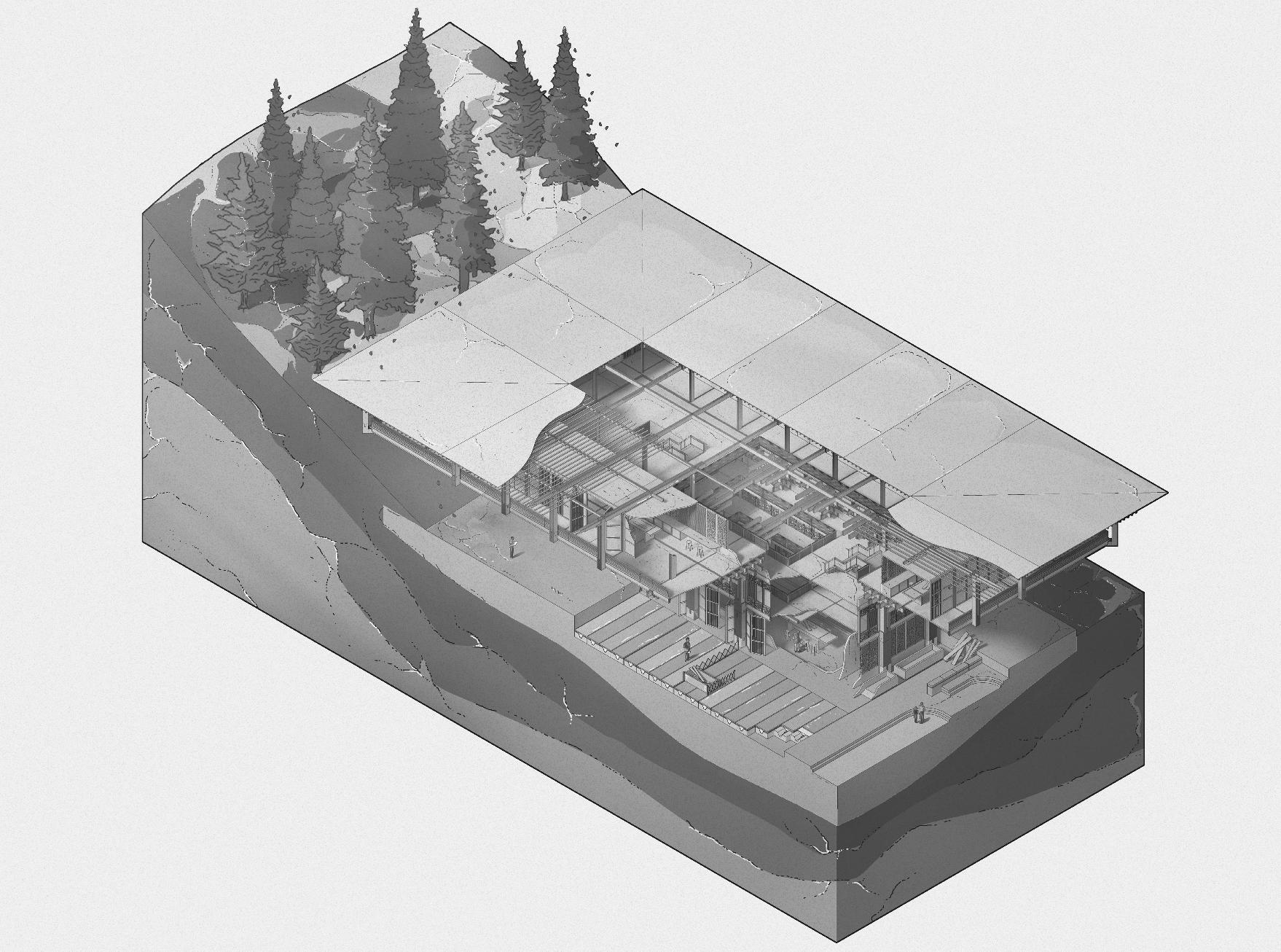
Bhutan has several hydroelectric projects underway as part of the nation’s Five Year Plans. The left diagram shows current proposed projects in Lhuentse in proximity to the site and the right diagram shows current electricity production in the country.
Renewable Energy Cycle
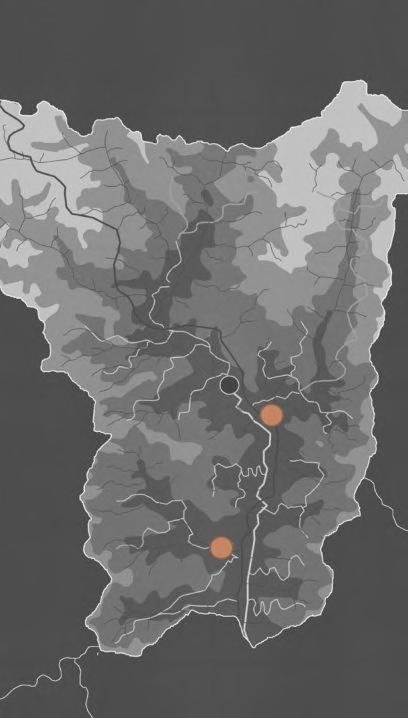
Section 5.02 99
Solar Power Output Carpentry Workshop Total solar panel area (m2): 162 Annual average solar irradiation (kWh/m2): 972 Energy generated (kWh): 162 x 22% x 972 x 0.8 = 27 714 kWh / year = 75.9 kWh / day Calculations for Water Sufficiency Carpentry Workshop Average annual rainfall (mm) = 2077 Roof area (m2) = 468 Annual water yield (L) = 1 411 520 Annual water demand (L) = 96 582 / 1 931 640 for 20 occupants Annual non-potable water saving (%) = 73 Bhutan’s Energy Network Underfloor heating Plant Grid Network
Slate roof tiles sit on a 4x6 grid on each roof section. Some that sit on the periphery are replaced with small scale PV panels. Switch DC AC
1. 4. 2. 3. 6.5. 9.10. 7.8 . 1. Reservoir 2. Intake 3. Control Gate Typical Hydroelectric Dam 4. Dam 5. Generator 6. Transformer 7. Powerhouse 8. Power lines 9. Turbine 10. Outflow A A TWh/year Year SITE Site Proposed Projects Hydro Exports Consumption Solar Power 15% Mechanics & Ventilation 21% Electric Tools 11% Textiles Fabric Dryer and Washer 18% Lighting 35% Kitchen Appliances Workshop Machinery & Computers Energy distribution across building Surplus EnergyValve openedHydroelectric power B B Poplar Decking Membrane Precast concrete slabs Concrete trenches with hot water pipes Site Resources
Heat Conservation The density of the external wall’s double dry stone build up retains heat during summer, and transfers it to keep it cool. Slate Roof Tiles PV Panels 30% 70% PV panels replace some roof tiles, covering 162m3 of the carpentry workshop roof. During the summer the workshop will receive an average of between 12-14 hours of sunlight per day. Mechanical extracts use energy generated by PV panels.
5.02A
Figure
Figure 5.02B
Figure 5.02C
Figure 5.02D
Office spaces and classrooms on upper storeys sit at a slightly higher altitude and therefore use ceiling vents to achieve cross ventilation and to prevent the build up of air pressure whilst retaining a semi-enclosed envelope.
Natural Ventilation
Diagrammatic Short Section through Painting Workshop
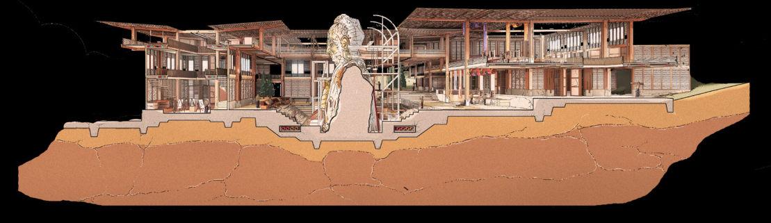
Each of the volumes across campus including the painting workshop predominantly rely on natural and passive ventilation to circulate oxygen and fresh air through a stack effect. The 14m tall workshop creates a buoyancy-driven ventilation system in which a pressure gradient between a low external pressure and higher internal pressure allows air to circulate to the exterior. The ground floor in-situ concrete slabs also preserve the earth’s thermal mass, cooling air, whilst allowing additional airflow through the labyrinth’s underfloor cooling system.
Ventilation & Cooling
Ventilation Requirements
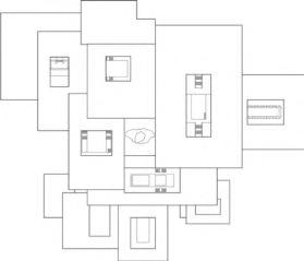
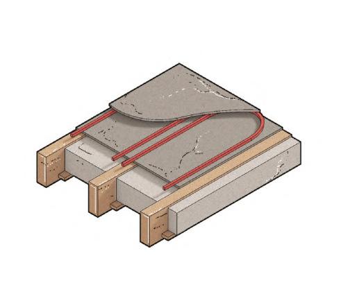
Skylights and rooflights provide the main source of escape for stale air throughout the campus. The amount of air moved through a stack effect can be calculated using the following equation:
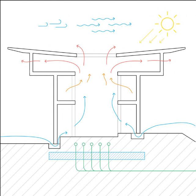
Q = Cd x A ((2/rins) Rins x g x (hnpl - h) (Tins - Tout/Tins))
Q = Air flow rate through a large opening (m3/s)
Cd = Discharge coefficient (0.61 for large openings)
A = Opening area (m2)
Rins = Air density inside stack (kg/m3)
g = Acceleration due to gravity (9.81 m/s2)
hnpl = Height of neutral pressure level above datum (m)
h = Height of opening above datum (m)
Tout = Temperature of air outside stack (oK)
Painting Workshop:
Q = Cd x A ((2/rins) Rins x g x (hnpl - h) ((Tins - Tout)/Tins))
Q = 0.61 x 4.5 ((2/1.19) 1.19 x 9.81 x (7 - 14) ((300294)/300))
Q = 2.75 ((1.68) 11.67 x (-7) (0.02))
Q = 7.55 m3/s
This equates to 27 180 m3 an hour when the average outside temperature in Lhuentse is 20oC. When the outside temperature reduces further, this figure could reduce, hence the labyrinth supplements the additional circulation of airflow.
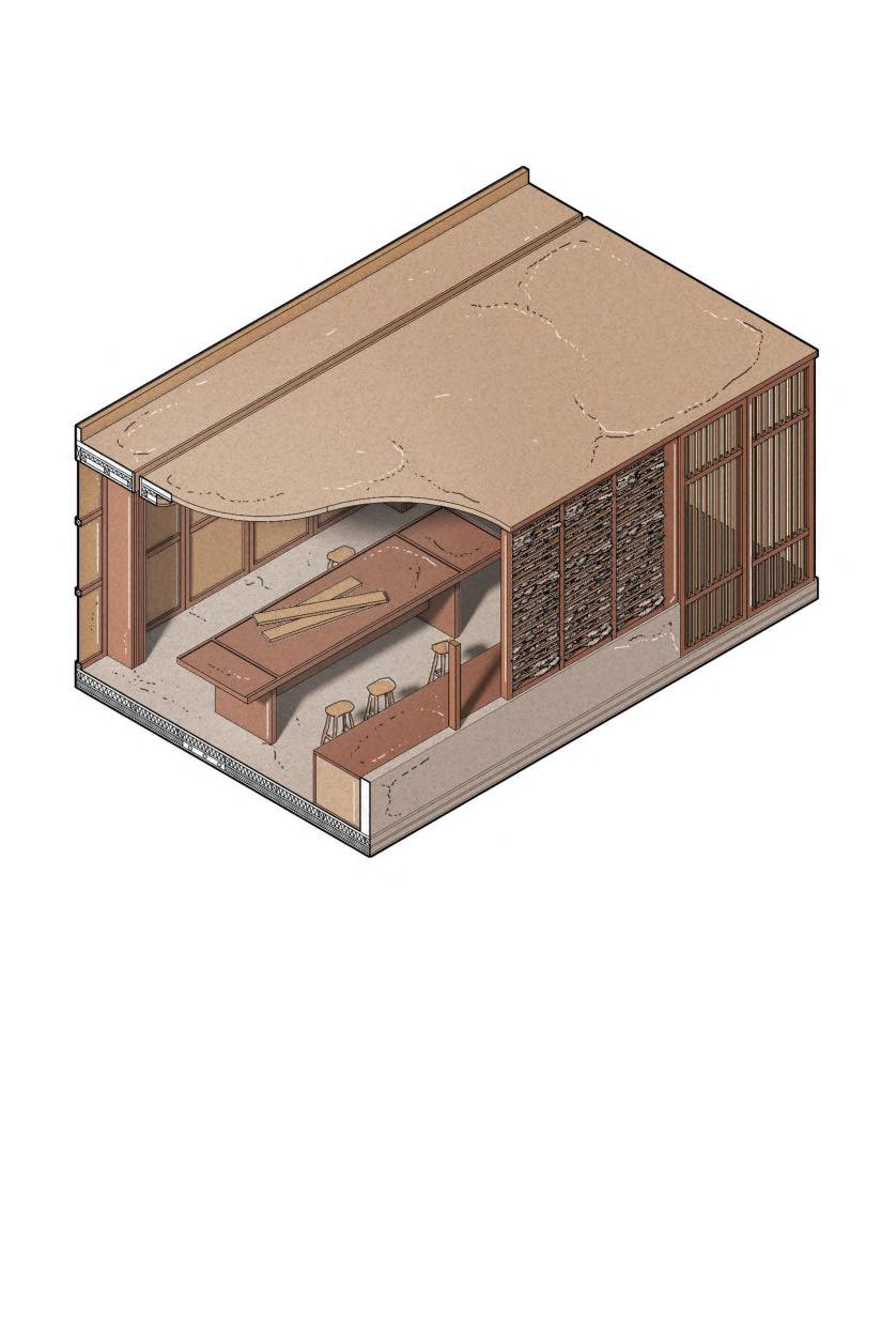
Underfloor heat exchangers adapt existing systems (shown right) to recycle water, taking it above the underground level, as a 6 metre height allows a sufficient amount of energy needed to distribute water around the building.
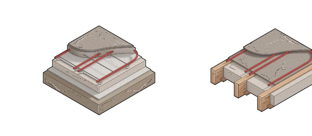
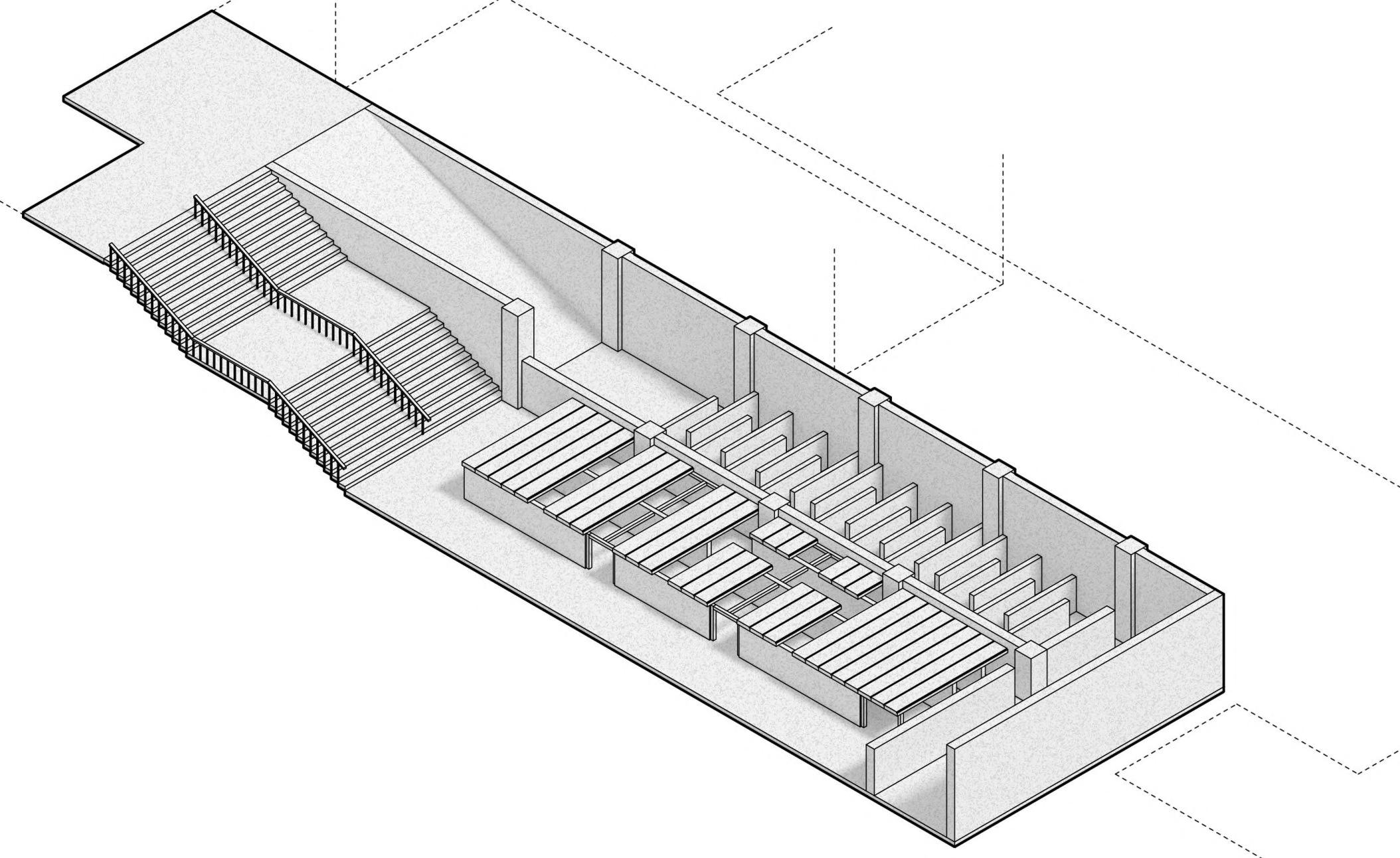
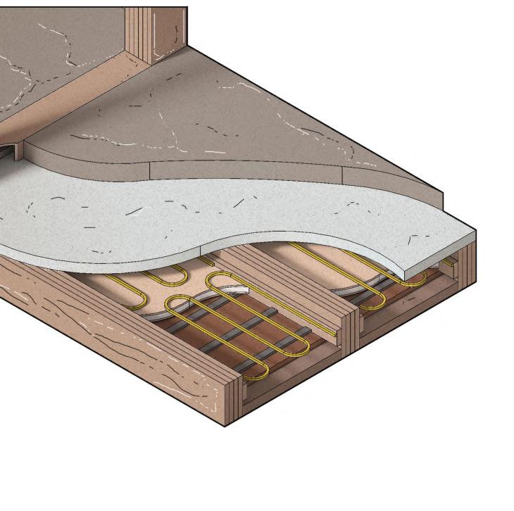
The underground thermal labyrinth beneath the textiles workshop and central courtyard behaves as a supplementary source of cooling through the building during the summer. It remains a low tech method that relies on the thermal mass of the basement to control internal temperatures. Heat exchangers (shown in section 5.01 & above) cool water which is distributed across the campus and help filter cool air.
Hot air contacts cool concrete which retains low temperature from previous day.
Heat exchangers pump cool water through campus, naturally filtering air. Mechanical air filters are therefore not required.
Section 5.03 100
Further Ventilation Underfloor Cooling
Precast concrete slabs allow ease of construction and maintain heat transfer between concrete and warm air. The ground earth allows geothermal heat from the ground to keep the labyrinth cool throughout the day.
Thermal Labyrinth Labyrinth Location A B
Roof air vents create cross ventilation and prevent build up of pressure.
Precast concrete floor slabs create watertight envelope to prevent build up of moisture. Underfloor cooling pipes supply cool air to rooms provided by heat exchangers in thermal labyrinth Precast concrete floor slabs Deodar wood floor joists Thermal Insulation Damp Proof Membrane A C B Concrete Slab System Floating Joists
Louvred doors create semi-enclosure.
C 1. South Westerly Wind Direction 2. Direct Sunlight 3. Hot air escapes through openable skylights 4. Air temperature increases as it rises 1.2. 3. 4. 5. 6. 7. 8. 5. Cool air intake 6. Floor cavity with vent for cool air intake 7. Concrete ground slab provides thermal mass 8. Cool water intake from thermal labyrinth Figure 5.03B
Figure 5.03A
5.03D
Figure
5.03C Figure
Section 5.04
Solar Gain Strategy
NATURAL LIGHTING
Lighting provides both illumination and solar gain across the campus. In addition to the use of PV panels, the use of demountable deodar wood beams create the flexibility for each workshop space to introduce a fabric insulation system (shown right) which enables both the thermal and experiential control of the interior. Moreover, the use of a stacked dry stone infill on the building’s outer skin allows perforations to create diffuse internal lighting whilst also ensuring a secure thermal barrier, reducing the need for thicker insulation in some areas.
DirectIllumination
The graph on the right shows the average monthly temperature in Lhuentse. The figures show that direct illumination can be achieved throughout the year in the building, through its south and east facing facades, restricting the need for artificial lighting to workshop spaces, studies, offices and underground levels. The building’s perforated stone skin also diffuses direct light to control excessive daylighting internally.
Daylight Penetration

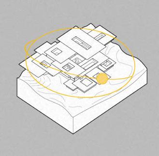
The left diagrams show the direction of daylight penetration at 10am throughout different times of the year. March 21st shows low angle lighting hitting internal spaces, while the cantilever blocks some high angle light; on June 21st, high angle light is blocked by the cantilever, with rooflights illuminating the central void and on September 22nd, low angle light penetrates the building’s external skin, and passes into the internal spaces.
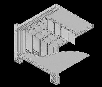
ThermalPerformance
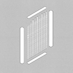
The use of a concrete plinth alongside the building’s dry stone/glulam hybrid outer skin creates a thick wall which prevents cold bridge penetrations and aims to reduce unwanted air leakages, creating a secure vapour and thermal
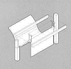
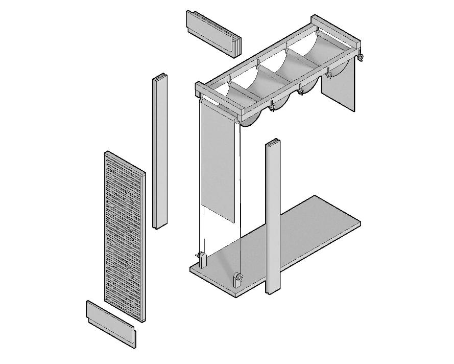
The first floor of the carpentry workshop may be re-purposed as a textiles workspace. The above, demountable solar shading system feeds fabrics produced by students and staff through a pulley system, providing shading and preventing the interior from overheating. The fabric’s Bhutanese patterns become a secondary skin for the facade (shown right). This system re-radiates heat internally, alongside the roof PV panels (as shown in diagram A above).
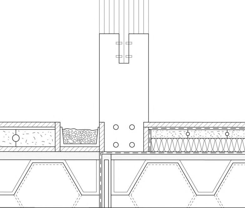
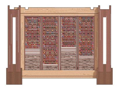
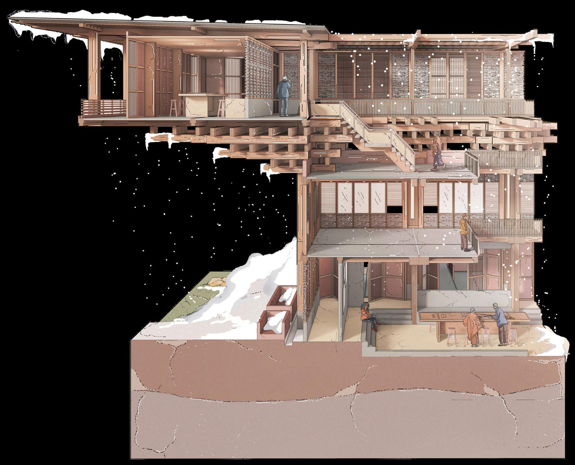
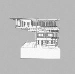
JFMAMJJASOND
101
The below calculations compare and consider the U-values for a typical envelope in the building using different types of insulation, their different thicknesses and thermal conductivity (K). Using the target U-Value of 0.22 W/m2K (taken from UK building regulations for walls in non-domestic spaces), 0.214 W/m2K aims to use wool to produce a well-insulated facade to improve internal comfort. Sheep’s Wool 178 0.039 W/mK 100 0.18 W/mK 1000.07 W/mK Thickness (mm) MaterialThermal Conductivity (K) Wool Fabric Concrete R-Value = t (thickness) / K (conductivity) U-Value = 1 / (R + R2 + R3 ...) U-Value = 1 / (3.84 + 0.83) = 0.214 W/m2K Sheep’s Wool Wool Fabric Concrete 3.84 m2K/W = 150/0.039 0.83 m2K/W = 150/0.18 2.86 m2K/W = 200/0.07
Solar Shading 0 C -12 C -7 C -1 C 4 C 10 C 16 C U-Values Sunlight Textile fabrics provide shading Worms Eye Isometric of Fabric Shading System Facade Bay Study Pulley System A. Sunpath Diagram Solar Shading - Previous Iteration Woven Fabric - Previous Iteration March 21st June 21st Sep 22nd Concrete plinth Thermal Line Waterproof Line Dowels Internal surface finish Waterproof Membrane Precast concrete ground slab Cast in-situ concrete trench foundation with hollow service cavity Rubble infill replaces water in channel during seasonal change A A High Angle Winter Sun Low Angle Summer Sun
5.04A
5.04D
Figure
Figure 5.04B Figure 5.04C Figure
ACOUSTICCONTROL
The central courtyard serves a dual function as an exhibition and outdoor workspace during the summer. The right drawings show the use of workspace infrastructure, both indoors and outdoors, to dampen sound from machinery. This is further reduced through the use of sound absorption materials (shown below) which minimise decibel levels, to ensure diffusion and reflection in particular does not affect communication in the courtyard’s open plan layout.
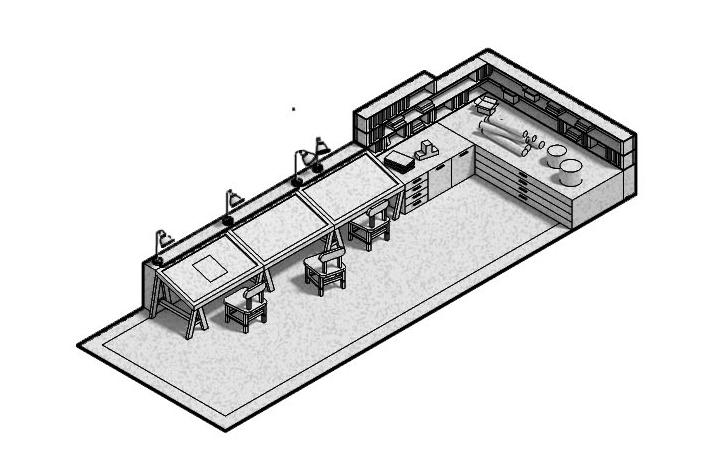
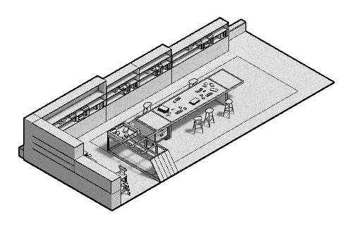
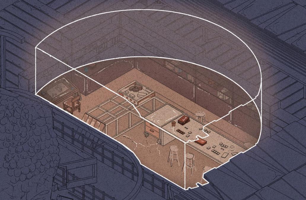
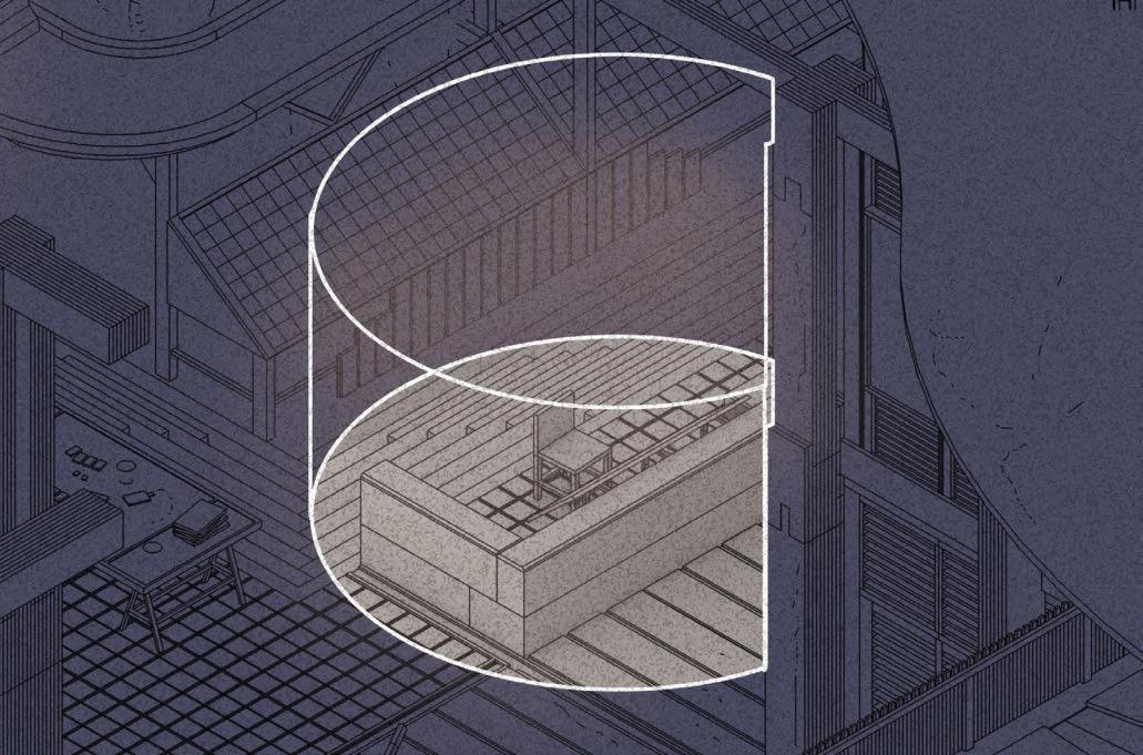
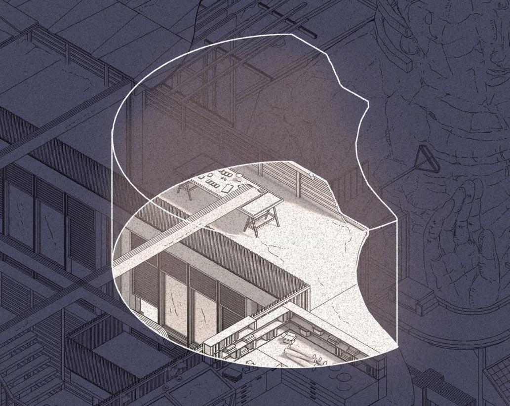
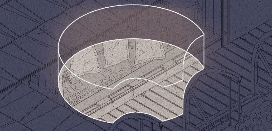
Reverberation time is the length of time required for sound to decay 60 decibels from its initial level. Indoor workspaces should have a reverberation time in the range of 0.4 to 0.6 seconds, but most workspaces have a time of 1 second or more, where:
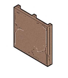
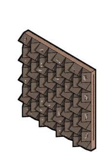
This low reverberation time makes up for the noise generated by outdoor workspaces. As illustrated in the left diagrams, reflection increases reverberation times, diffusion spreads the sound but does not reduce it, and absorption reduces sound levels and reverberation times, which should be maximised.
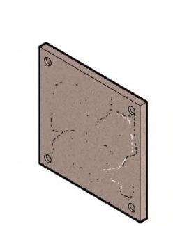
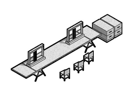
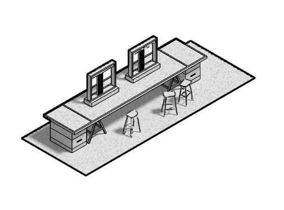
Workspace as Acoustic Buffer
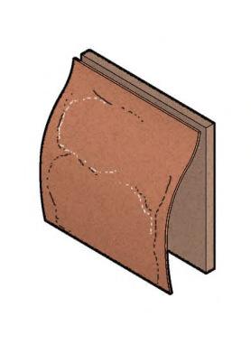
Section 5.05 102
Acoustics
RT (60) = Reverberation Time (sec) V = Room Volume (m3) S = Surface Area (m2) A = Absorption coefficient of material (s) at given frequency E = Indicates the summation of S times for all room surfaces RT = 0.05V/ESa Each workspace is approximately 125 m2 where: Glazing: 18 m2 μ = 0.04 (500 Hz) Fabric: 72 m2 μ = 0.65 (500 Hz) Timber: 81 m2 μ = 0.15 (500 Hz) Concrete: 54 m2 μ = 0.02 (500 Hz) 0.05 x 125 / (18 x 0.04) + (72 x 0.65) + (81 x 0.15) + (54 x 0.02) = 0.1s Reflection Absorption Diffusion
ReverberationTime Each of the materials below can be deployed to alter sound diffusion across the building. Each material has an absorption coefficient (μ) which indicates the ratio of energy absorbed by a material to the energy incident upon it surface, 1 being full absorption and 0 being full reflection. Fabric with backboard 0.5kg/m3 μ = 0.65 (500 Hz) Used in textiles workshops to help reduce reverberation times. Absorption Panel μ = 0.8 (500 Hz) Used in workspace infrastructure. Timber μ = 0.15 (500 Hz) Primary building structure/ cladding. Its high absorption coefficient helps with sound. Concrete μ = 0.02 (500 Hz) Used as ground and upper storey floor slabs and plinth/ foundations. Glazing μ = 0.04 (500 Hz) Used for windows. A B C D A B C D Outdoor Workspace Carpentry Textiles Textiles Central Sculpture Indoor Workspace Outdoor Workspace Indoor Workspace Outdoor Workspace Outdoor Workspace Outdoor Workspace Outdoor Workspace
5.05A
5.05C Figure 5.05B
Figure
Figure
IN CONSTRUCTION
ISSUE
Ground water flooding.
Noise disturbance caused my machinery and diggers.
SOLUTION
Pumping and ensuring ground floor is sealed by waterproof and damp proof membrane.
Noise barriers and managed construction time during early off-peak hours.
IN OPERATION
Potential damage to earth and nearby small scale dwellings.
Temporary bamboo scaffolding and underpinning system.
ISSUE
Fire risk.
Noise disturbance to local residences.


Accidental clashes between cyclists, students and staff.


Building users falling over steps.


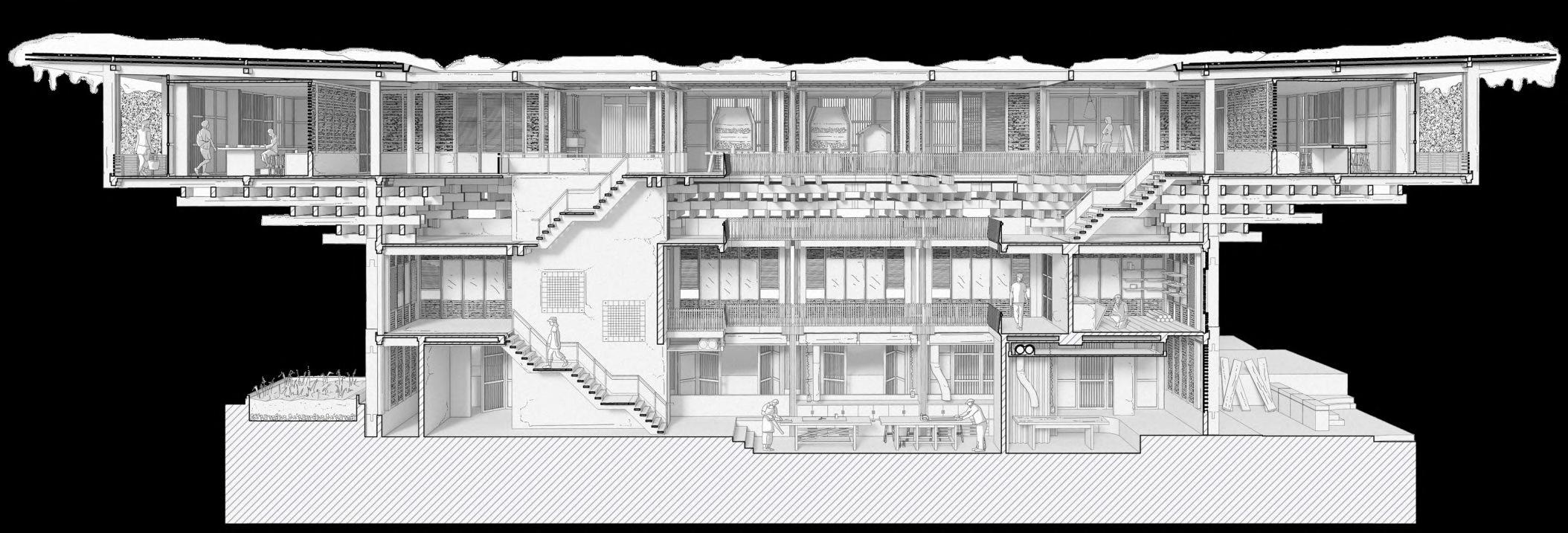
Slipping on wet surfaces.
Disabled access.
SOLUTION
Sprinkler system, external fire escape routes and fire resistant finishes.

Use of absorption panels in workspaces as acoustic buffers.
Clear circulation between staff, students and the public.
Use of slip resistant and durable surfaces.
Integrated drainage system for redistribution of rainwater in channels across campus.
Use of lifts in painting and carpentry workshops for disabled access across entire campus.

Health & Safety Section 5.06 103
CarpentryWorkshop Section
Figure 5.06A
Fire Strategy
FIRE CONTROL
The campus has multiple escape routes at every elevation, which extend to external assembly points during the event of a fire. The combined volumes each use an independent exit that transfer people from the inside to the outside, allowing for safer access to outdoor assembly. Alongside the use of stone in fire control, the building’s primary glulam structure is also treated with a fire resistant coating to reduce the rate at which fire could spread. Sprinklers, fire extinguishers, fire protected escape stairs, and shared emergency service site access and egress routes create safer fire control in workshops and across the campus. In addition, the building’s location at a high altitude and the limited oxygen reduces the risk of fire spread.
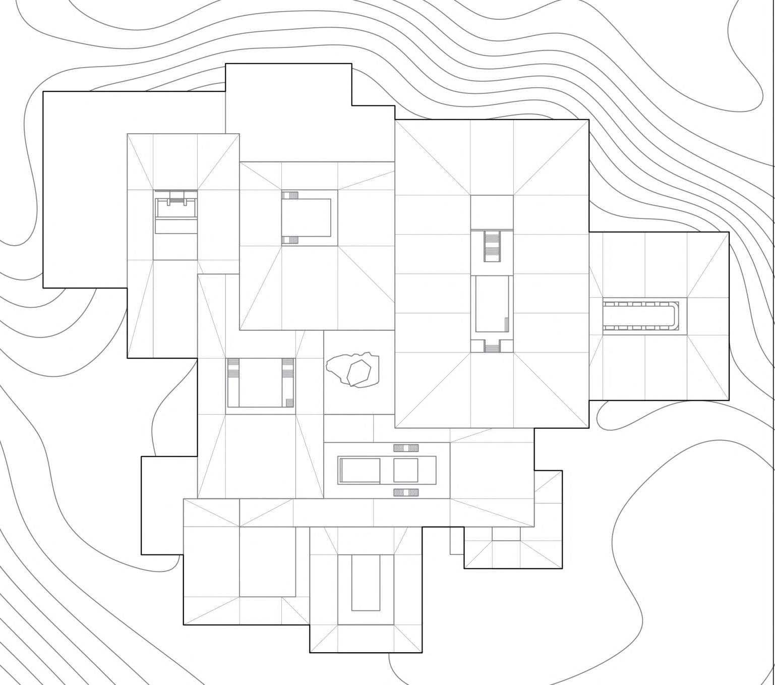
BeforeAfter
StructuralIntegrity
The diagram above illustrates the charring of typical glulam columns in the event of a fire. The columns are treated with fire resistant coating, insulating the wood from heat damage and maintaining the primary glulam frame’s structural integrity. The glulam timber achieves a fire resistance rating of two hours when exposed to fire.
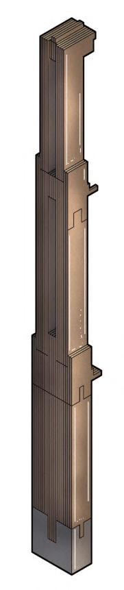
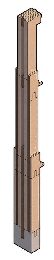
2 hours + fire resistance
4 hours + resistance
Key
Designated Fire Assembly Point
Emergency Service Site Access
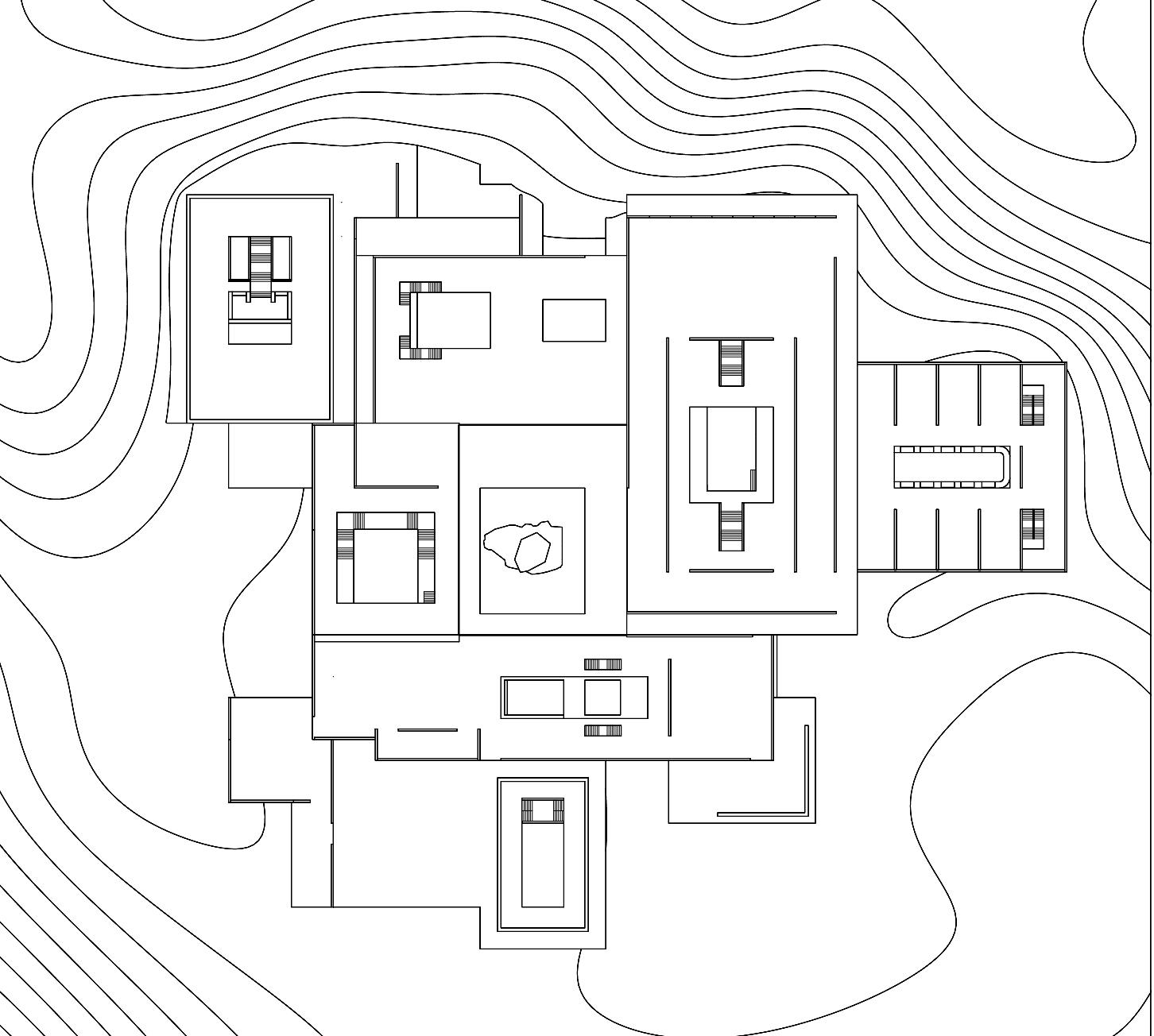
Fire Protected Escape Stair
Emergency Egress Route
Integrated Sprinkler System
Mounted Fire Extinguisher
Section 5.07 104
ROOFPLAN
LEVEL02&03PLAN
Figure 5.07A
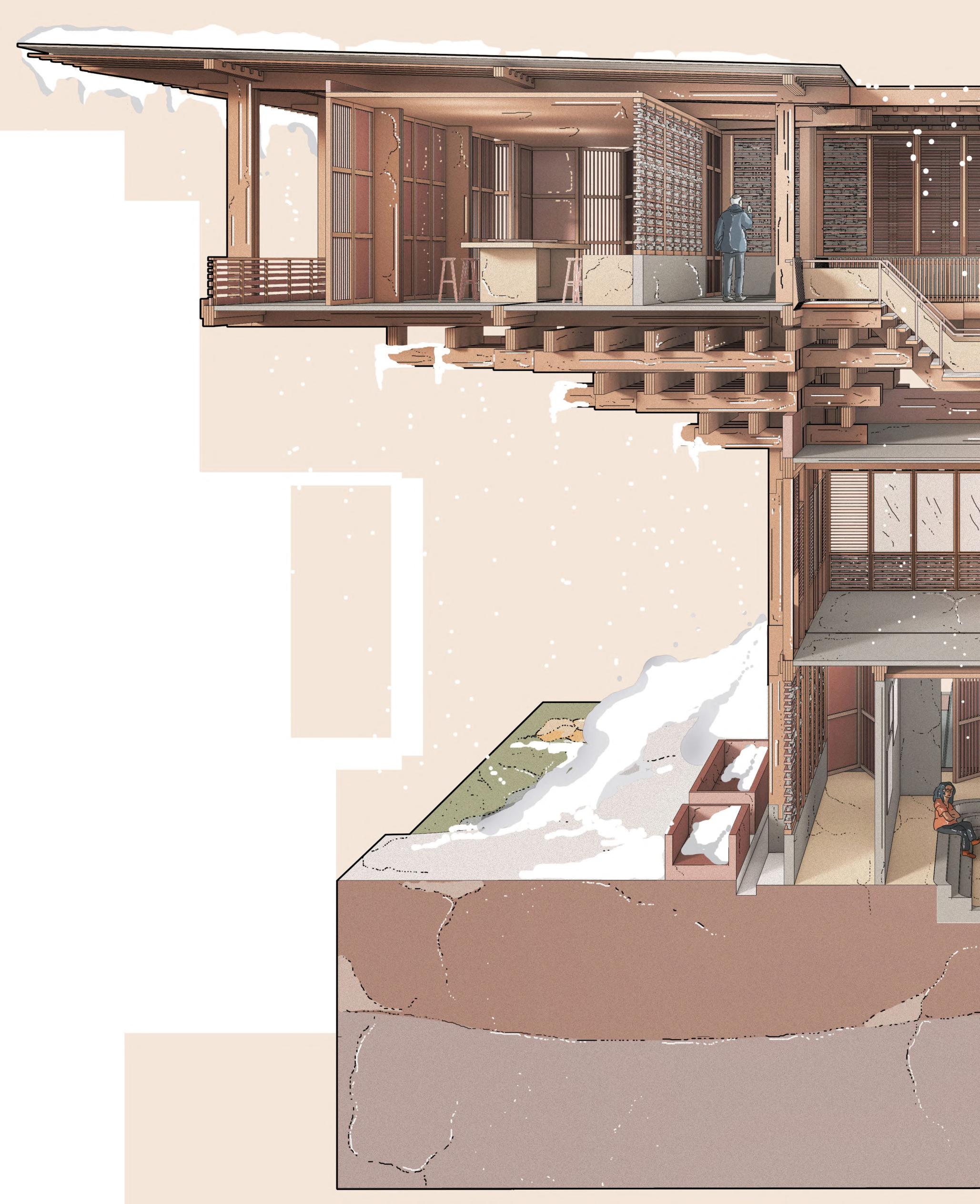
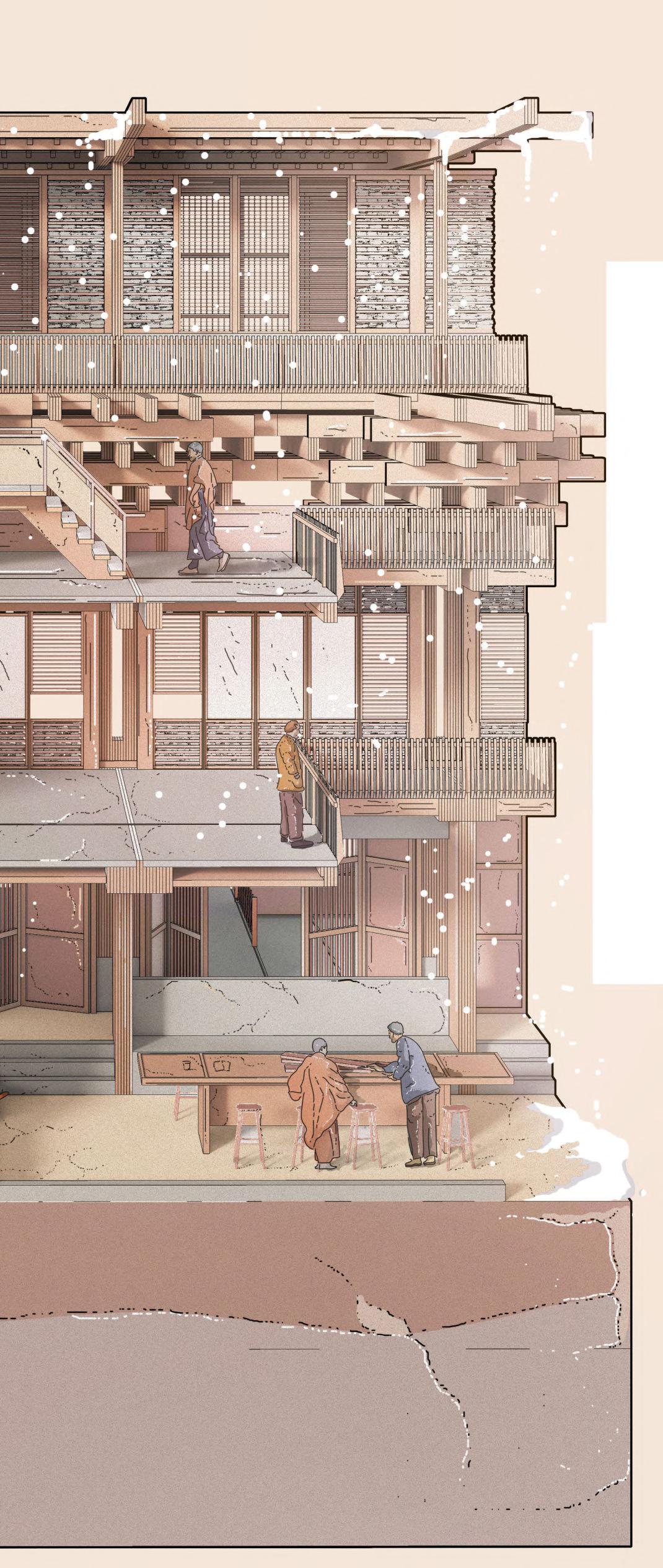
FINAL DRAWINGS 06 LHUENTSE SCHOOL OF CRAFTS 106 Chapter BARC0174 _ AAD1
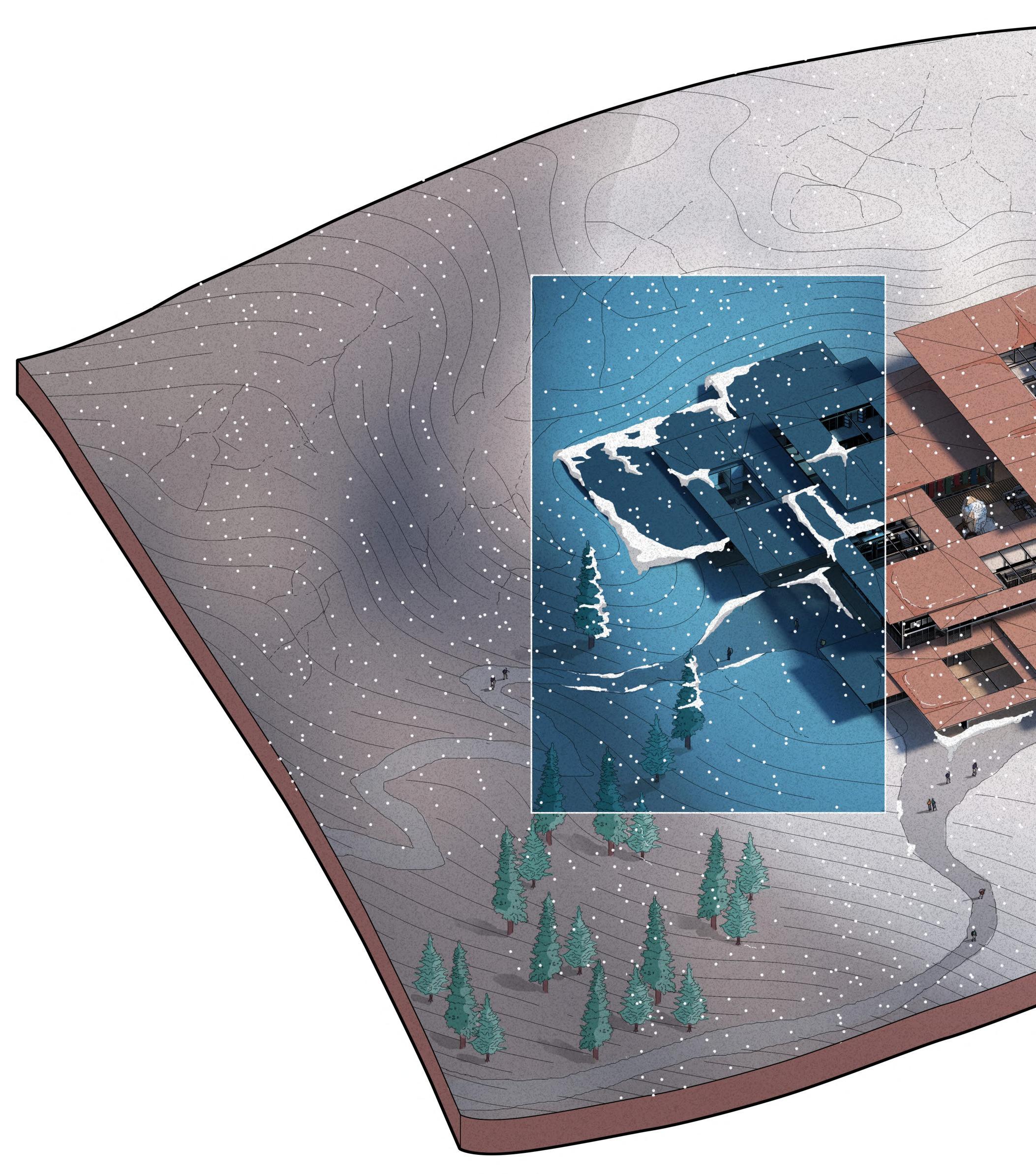
Aerial View Section 6.01
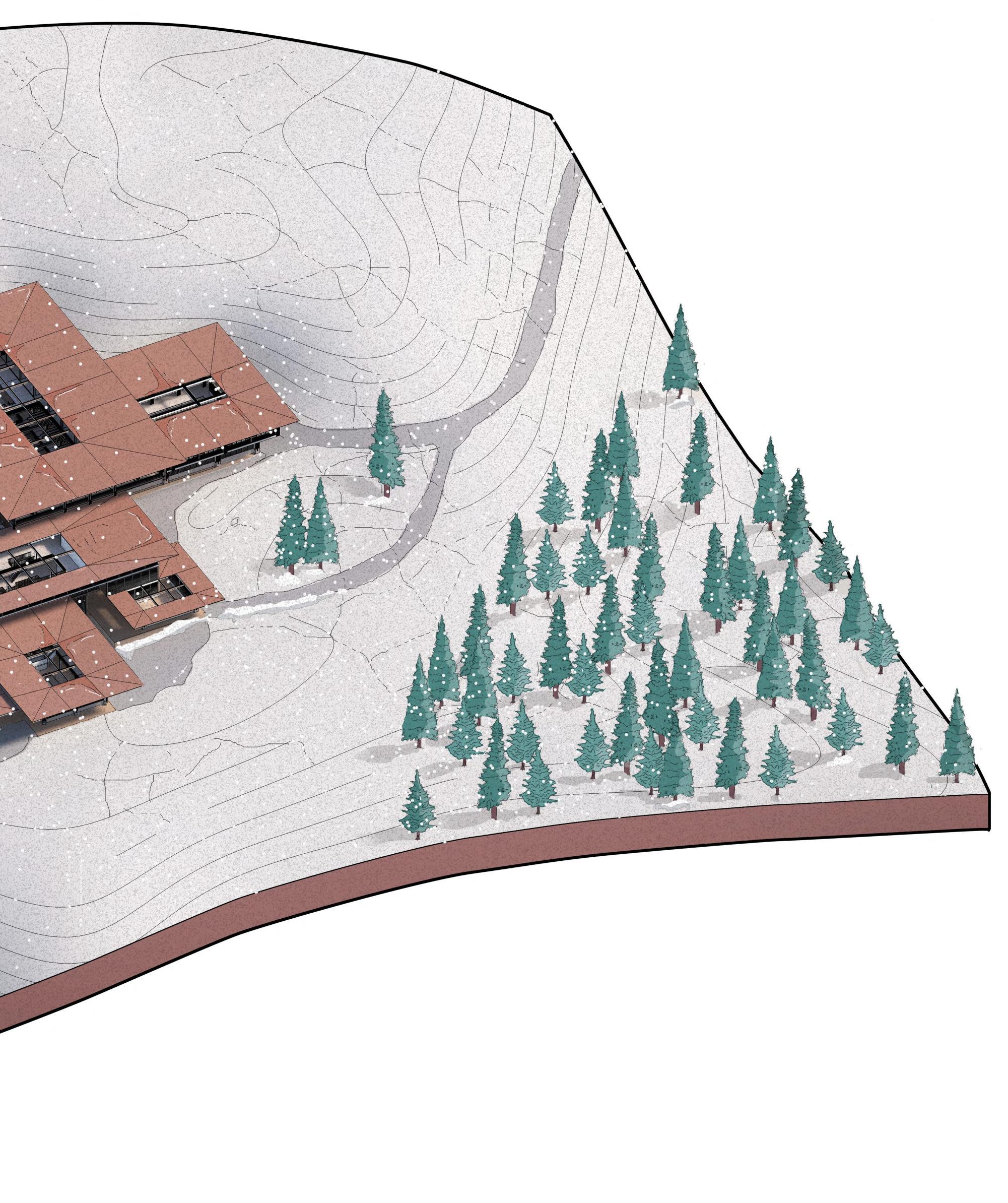

CHAPTER 6 _ FINAL DRAWINGS BARC0174 _ AAD1 108
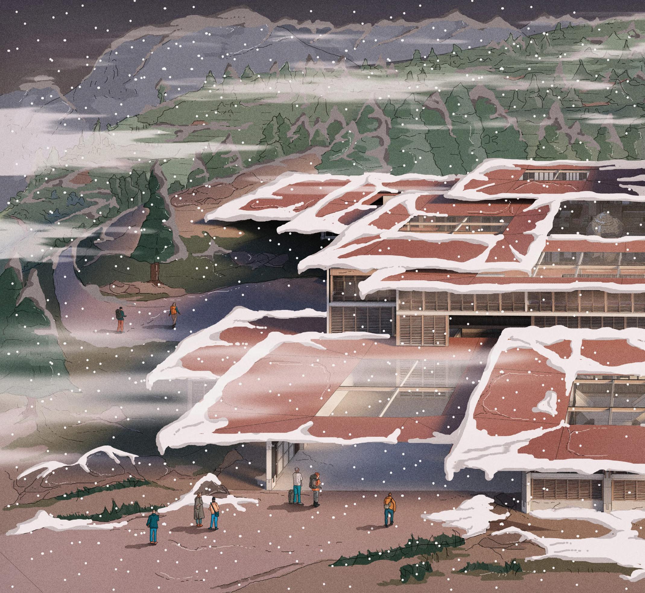
Aerial Entrance View Section 6.02
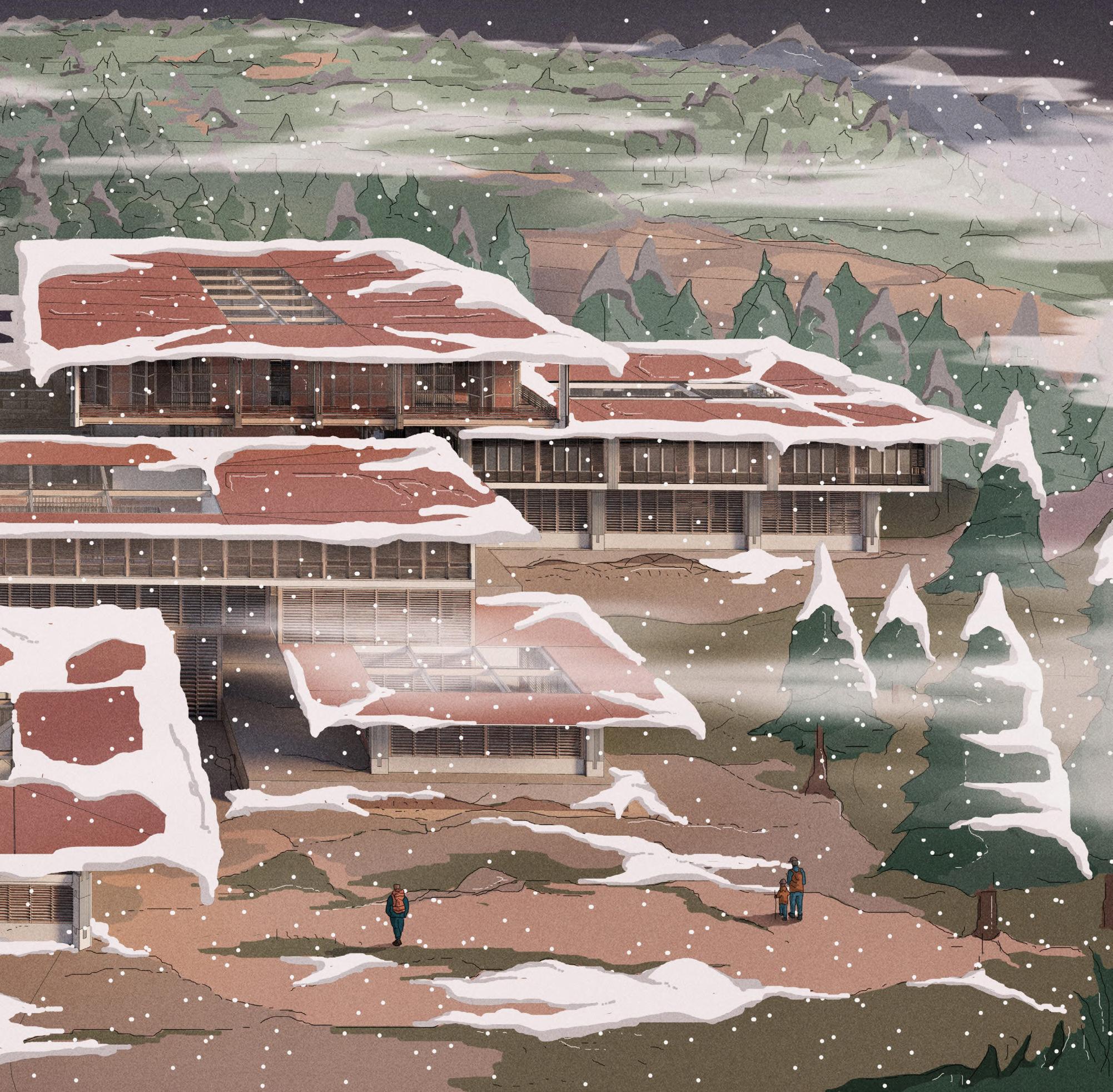
CHAPTER 6 _ FINAL DRAWINGS BARC0174 _ AAD1 110
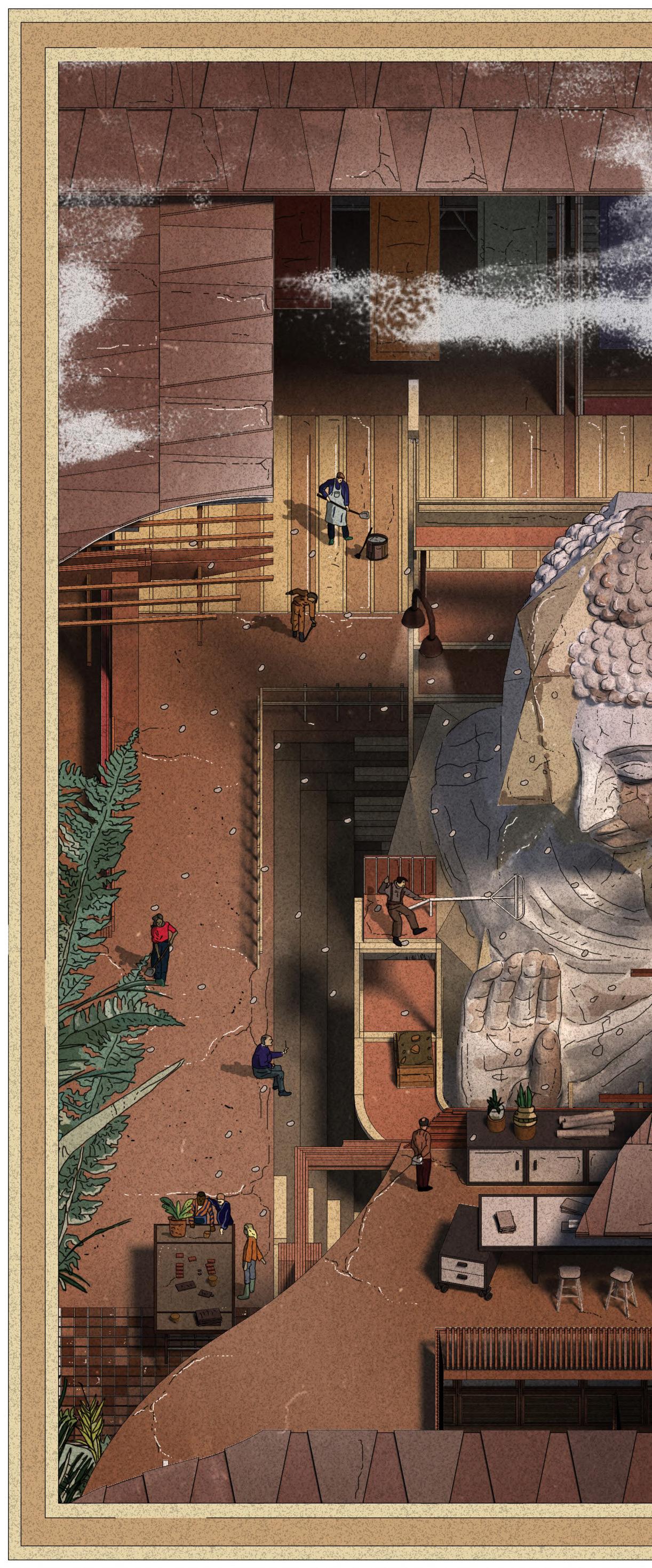
Section 6.03
Central Courtyard
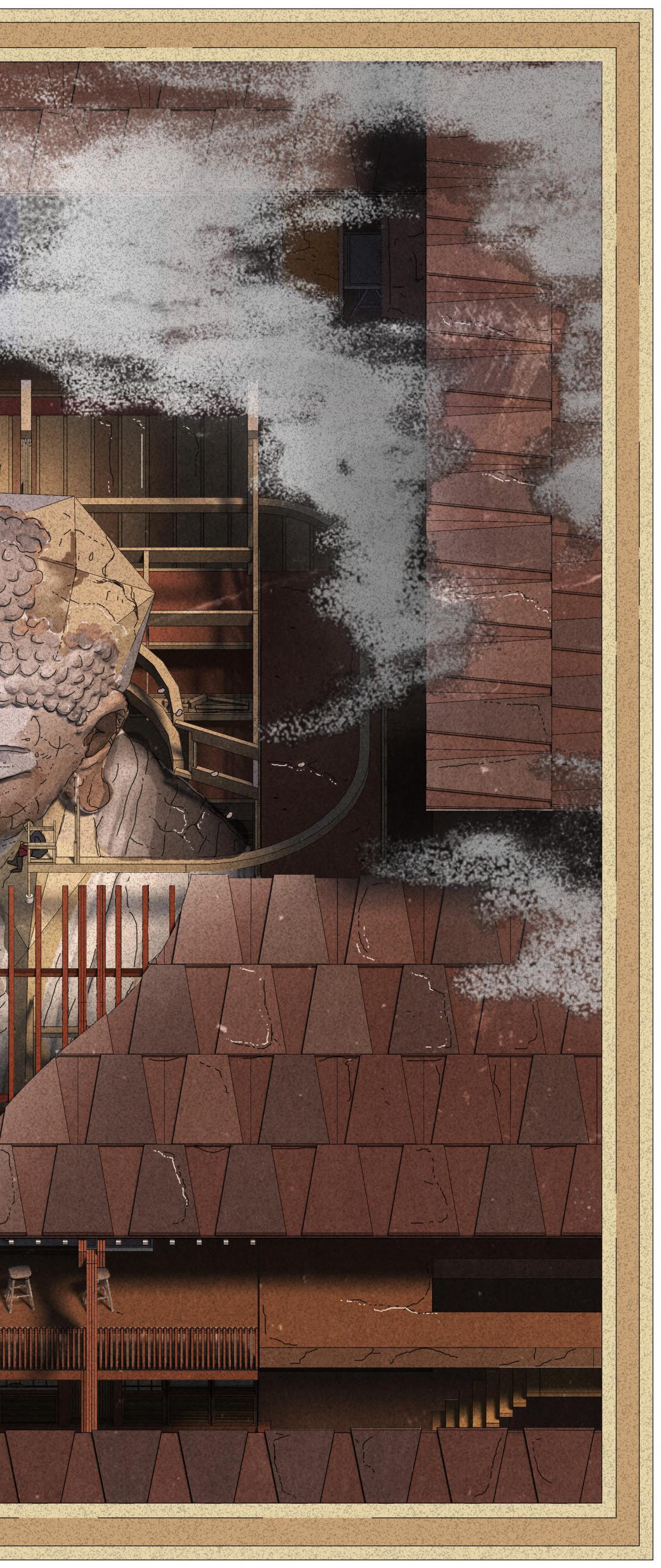
CHAPTER 6 _ FINAL DRAWINGS BARC0174 _ AAD1 112
Carpentry Workshop Fragment
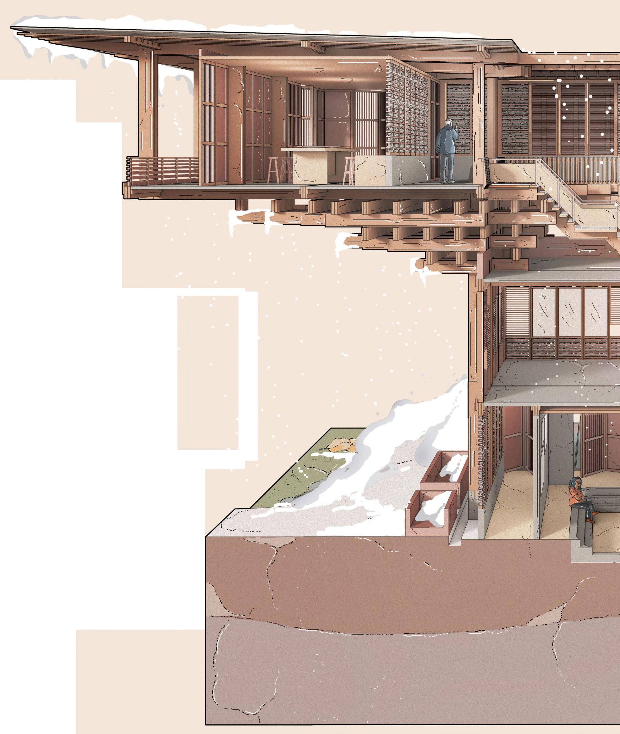
Section 6.04
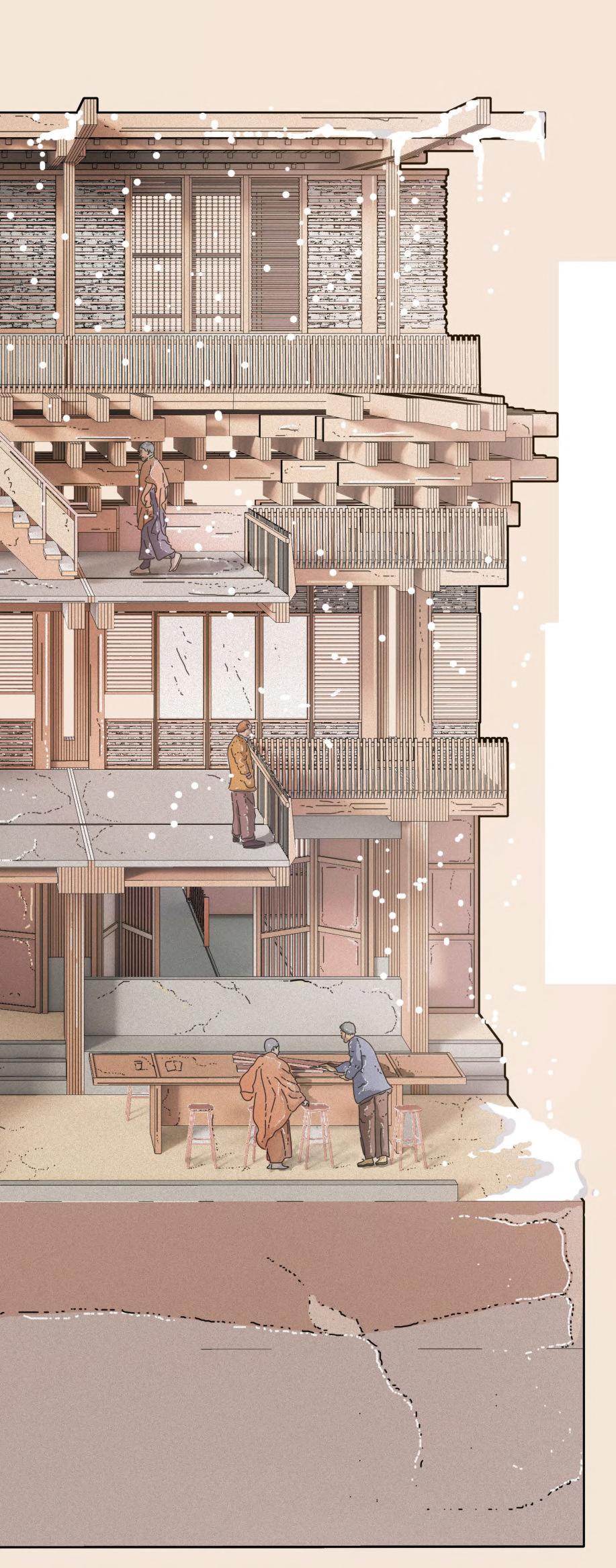
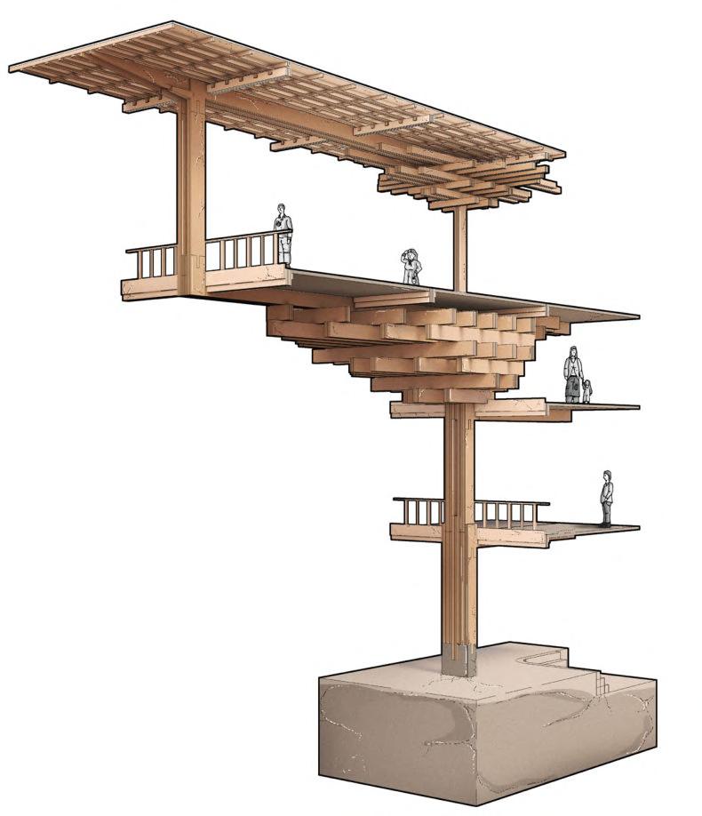
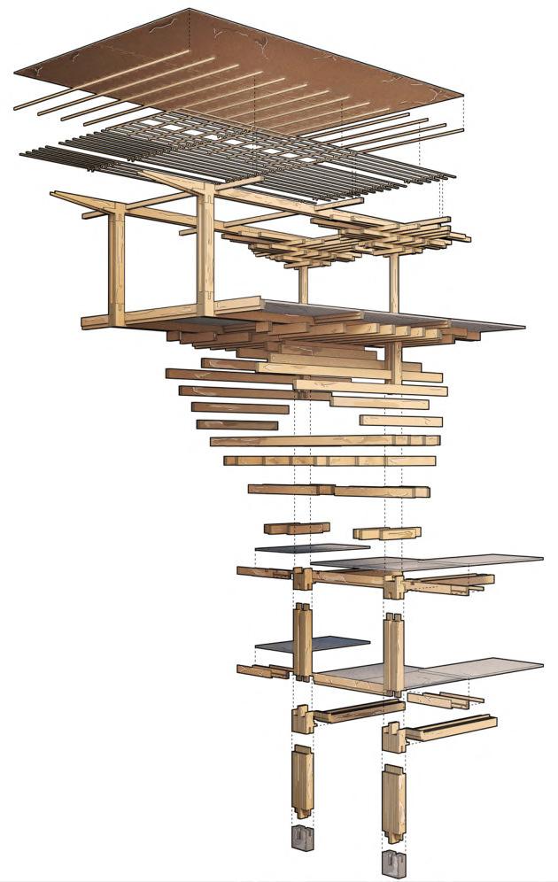
CHAPTER 6 _ FINAL DRAWINGS BARC0174 _ AAD1 114
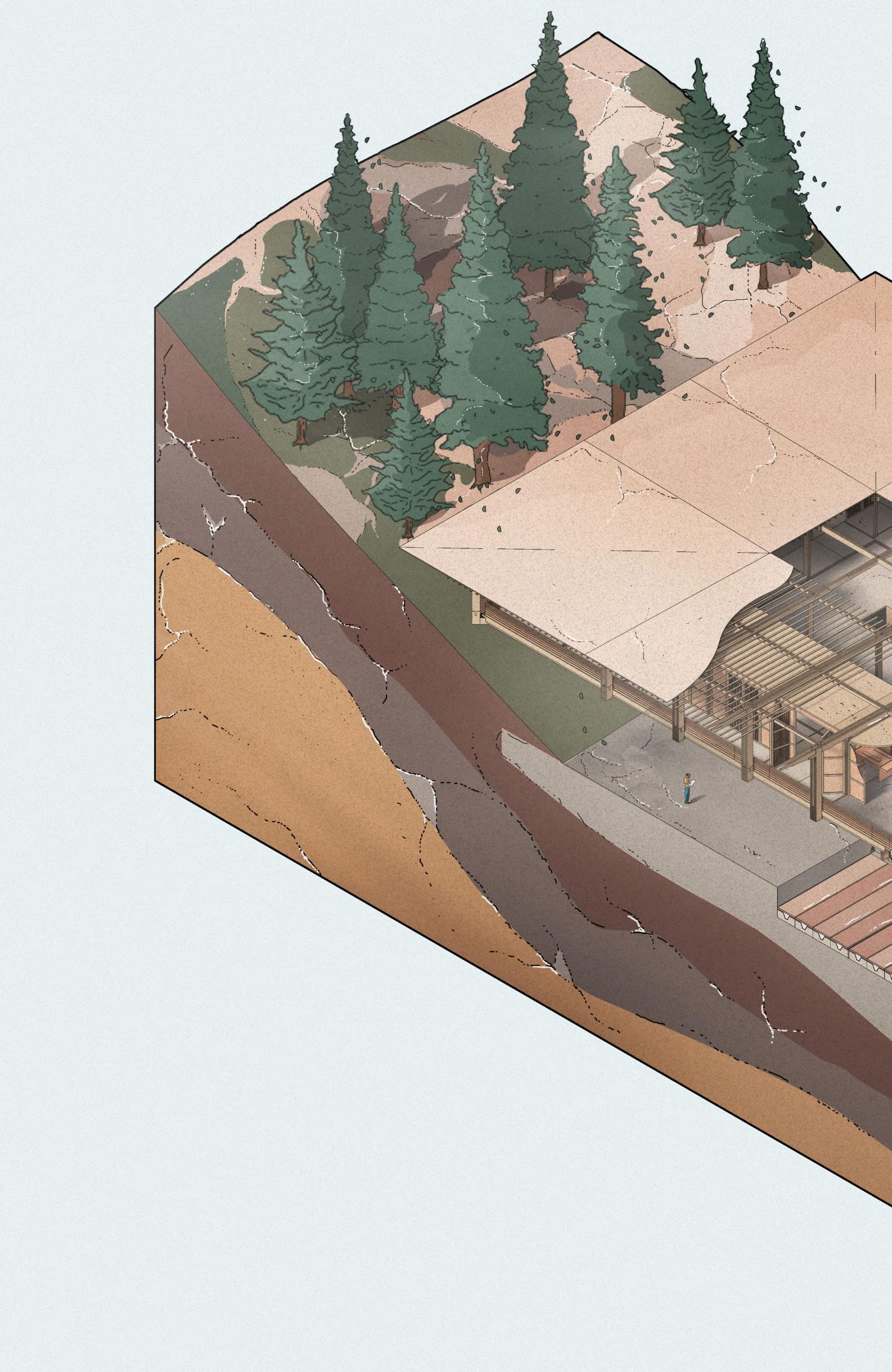


Section 6.05
Carpentry Workshop
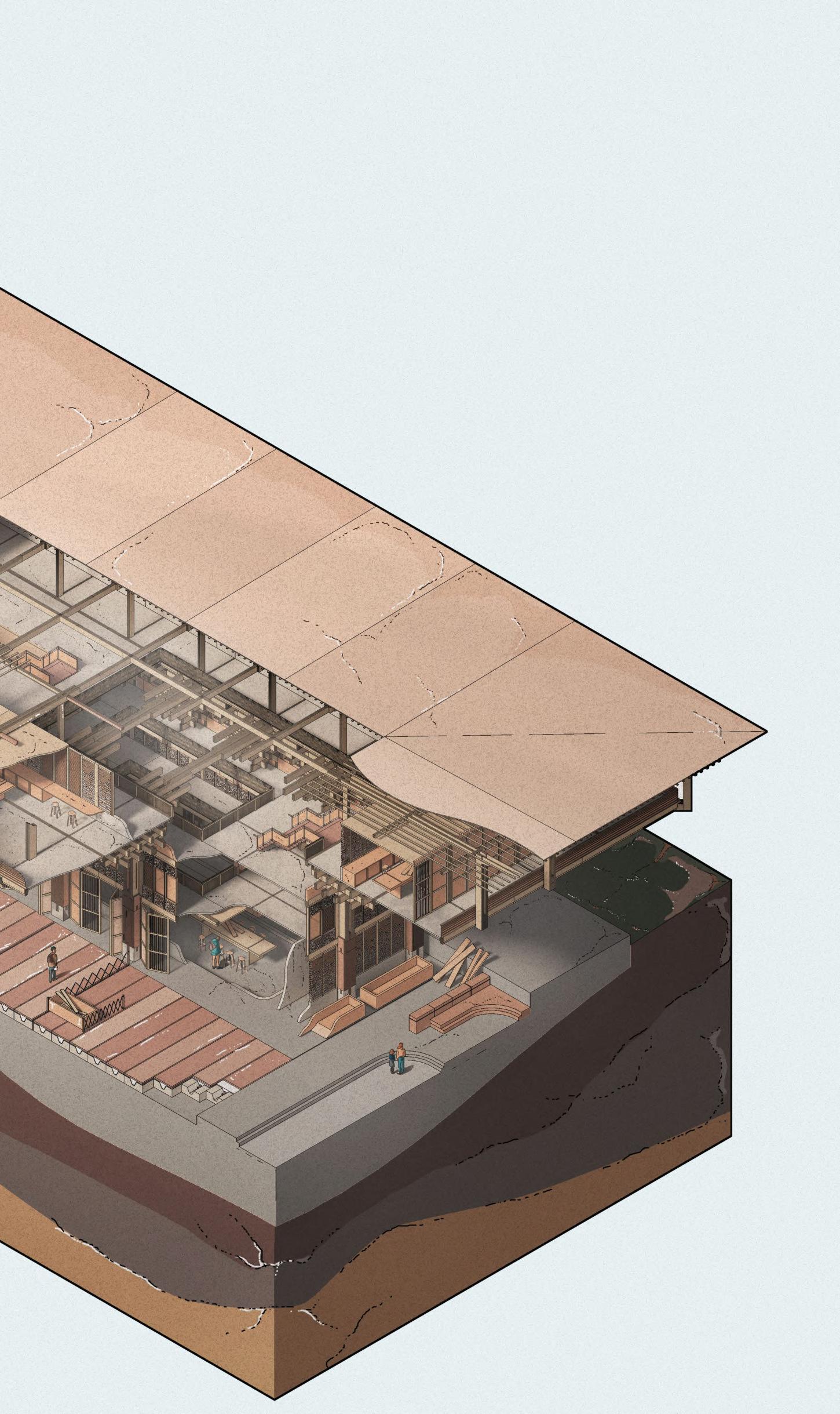

CHAPTER 6 _ FINAL DRAWINGS BARC0174 _ AAD1 116
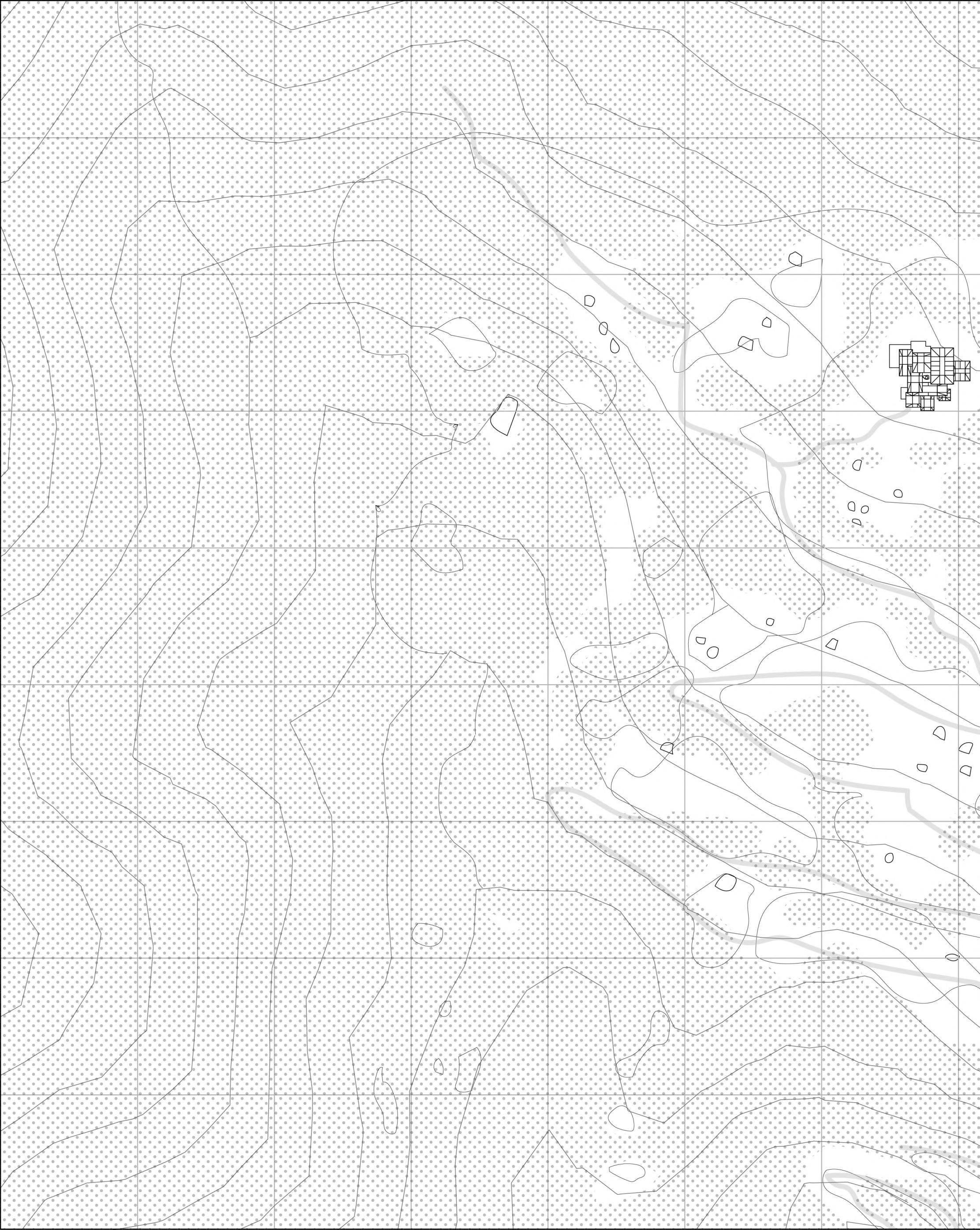
Site Plan 1:5000 @ A2 Section 6.06
Treecoverage
Roadsandfootpaths
NB. Everycontourlinerepresents50m

0m50m150m200m
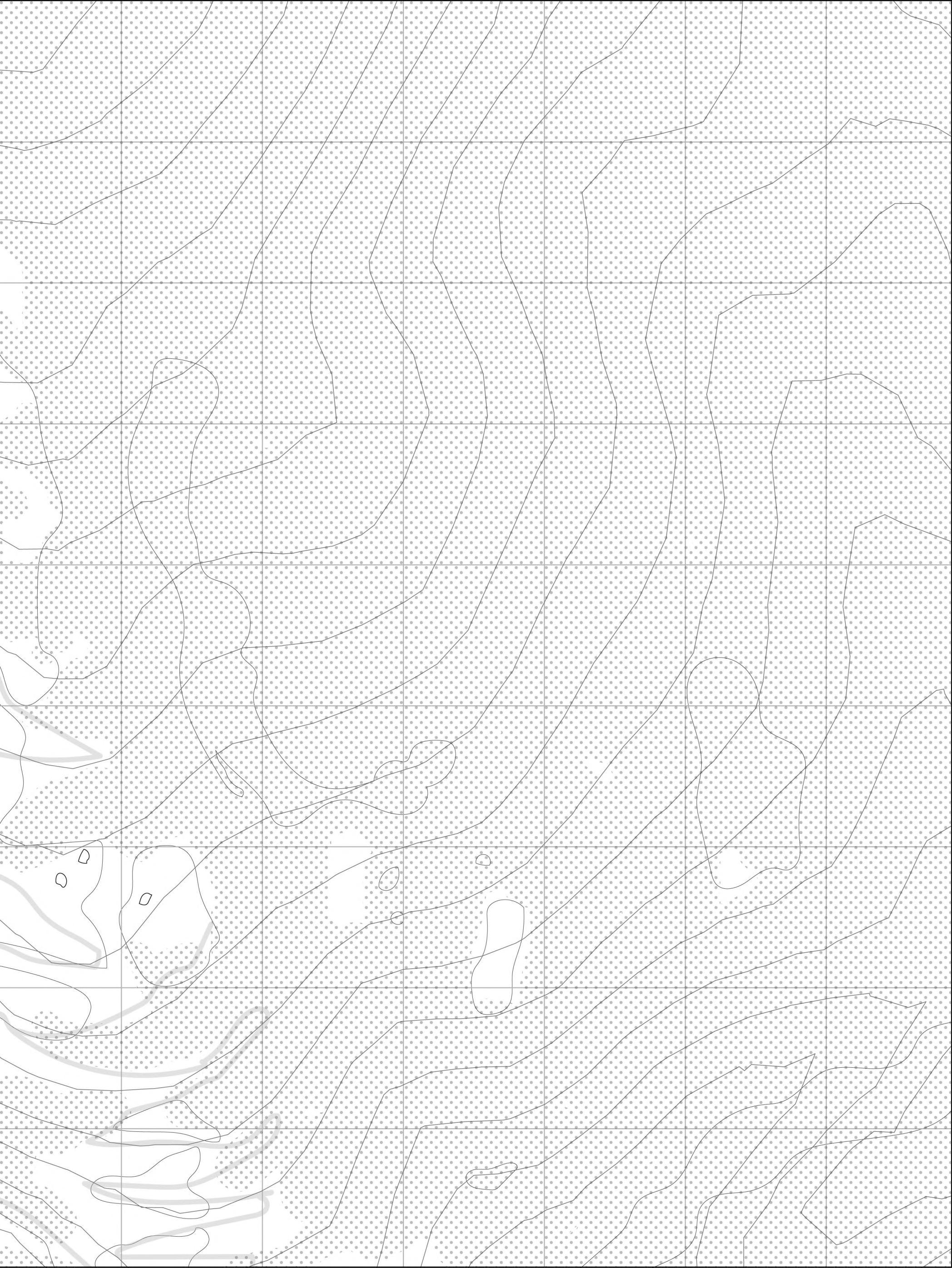
CHAPTER 6 _ FINAL DRAWINGS BARC0174 _ AAD1 118
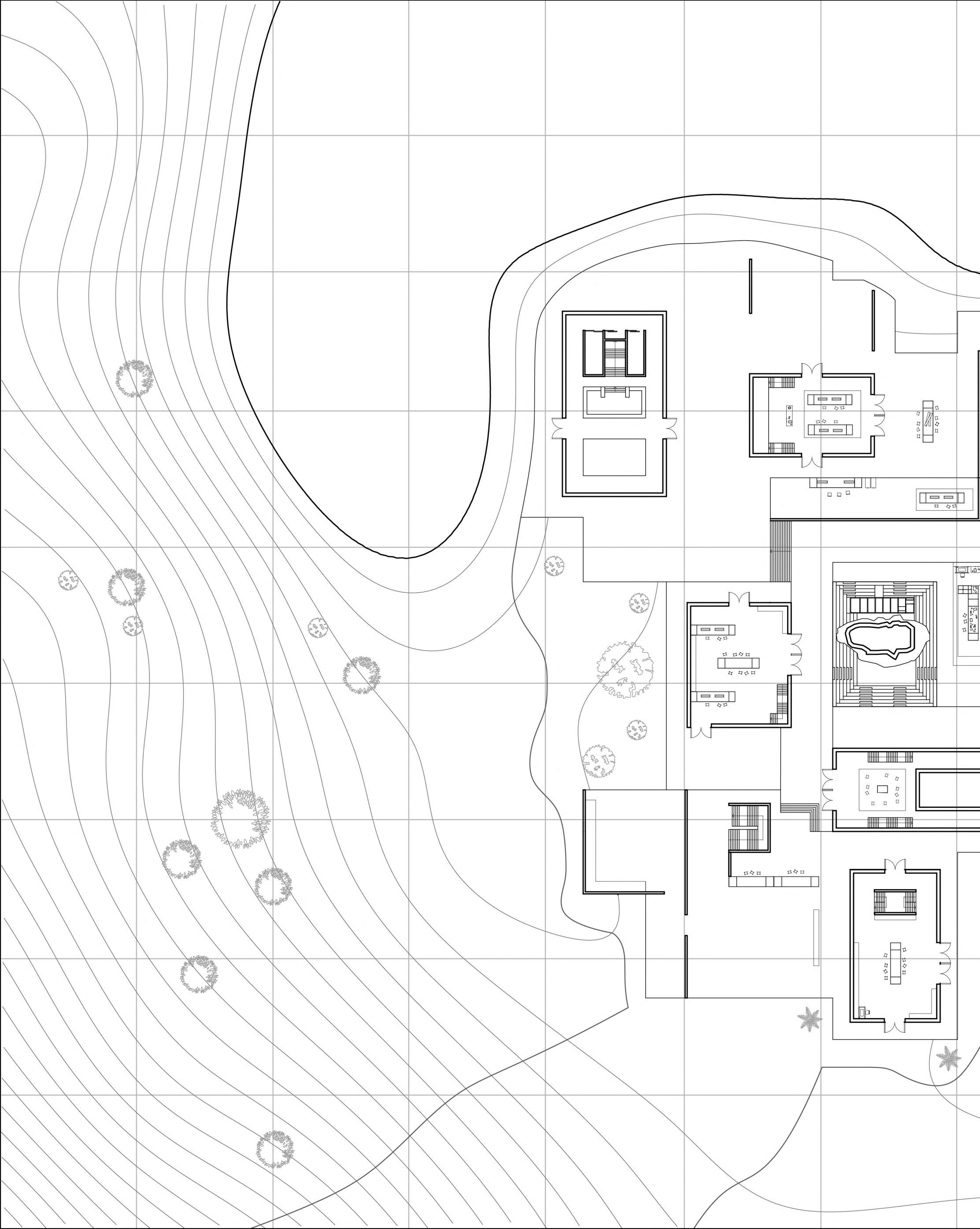
Ground Floor Plan 1:500 @ A2 Section 6.07 01 A A 02 03 04 08 11 18 10 09 06 05 12 16
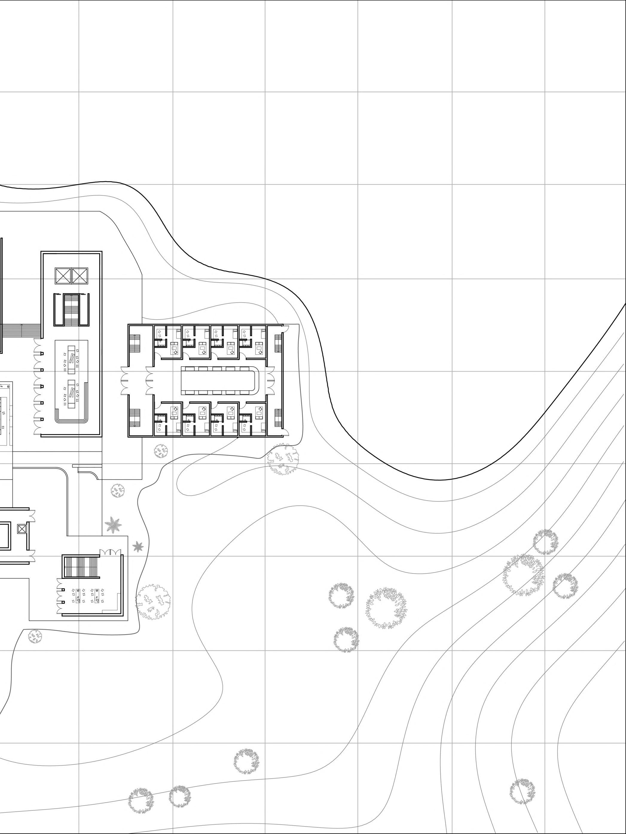
120 01 EntrancePath 02 EntranceLobby 03 WaitingArea 04 Entrance&PublicInformation 05 Security 06 PaintingWorkshop1 07 PaintingWorkshop2 08 TextilesWorkshop1 09 CentralCourtyard,Outdoor Workspace&ExhibitionSpace 10 ServiceAccess 11 MultipurposeAuditorium&Dining Hall 12 TextilesWorkshop2 13 ThermalLabyrinthAccess 14 CarpentryWorkshop 15 Dormitories 16 OutdoorCourtyard 17 OutdoorCourtyard 18 ServiceZone 0m3m9m 18m 27m 07 14 15 13 17 CHAPTER 6 _ FINAL DRAWINGS BARC0174 _ AAD1
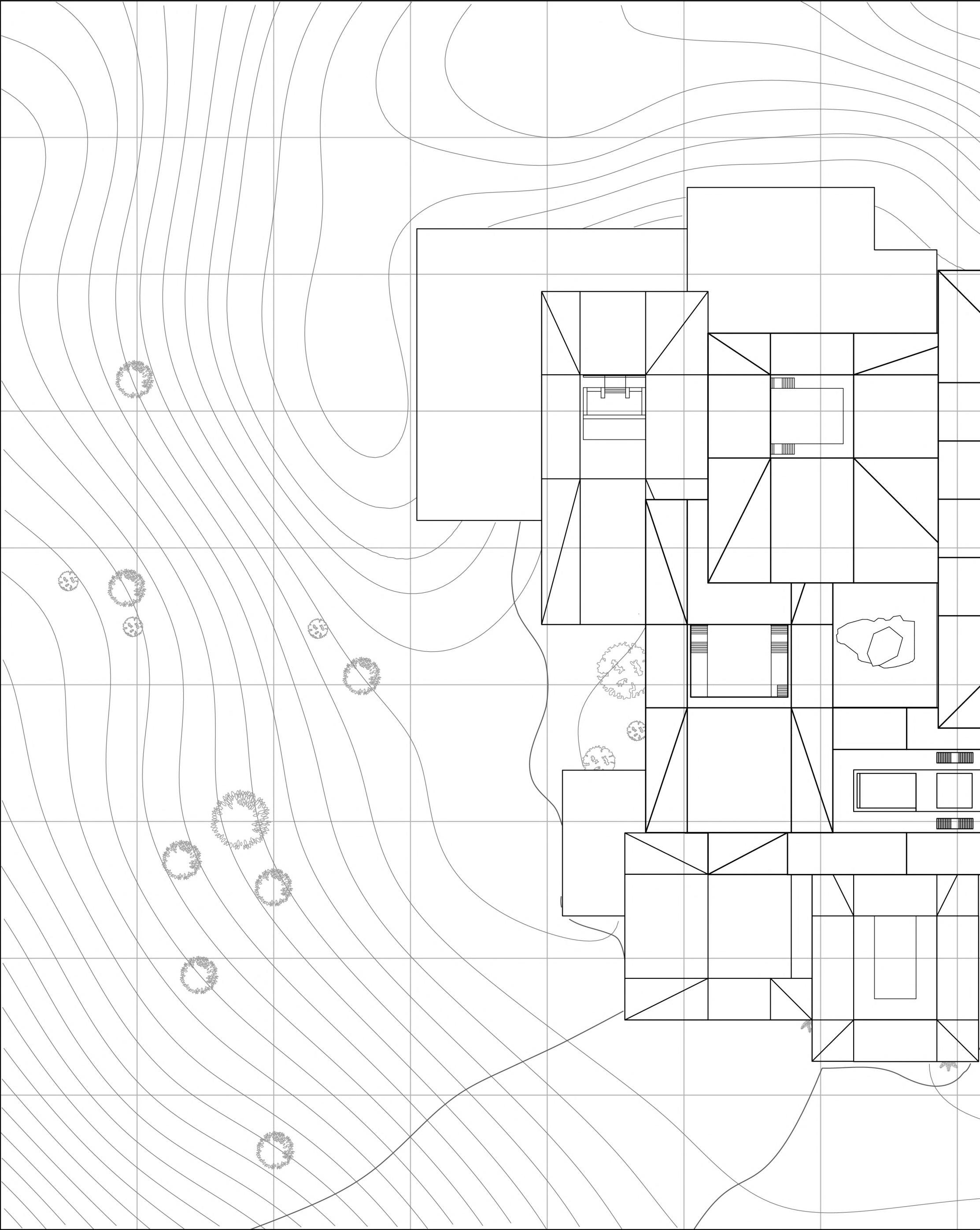
Roof Plan 1:500 @ A2 Section 6.08 01 A A 02 03 04 08 11 18 10 09 06 05 12 16
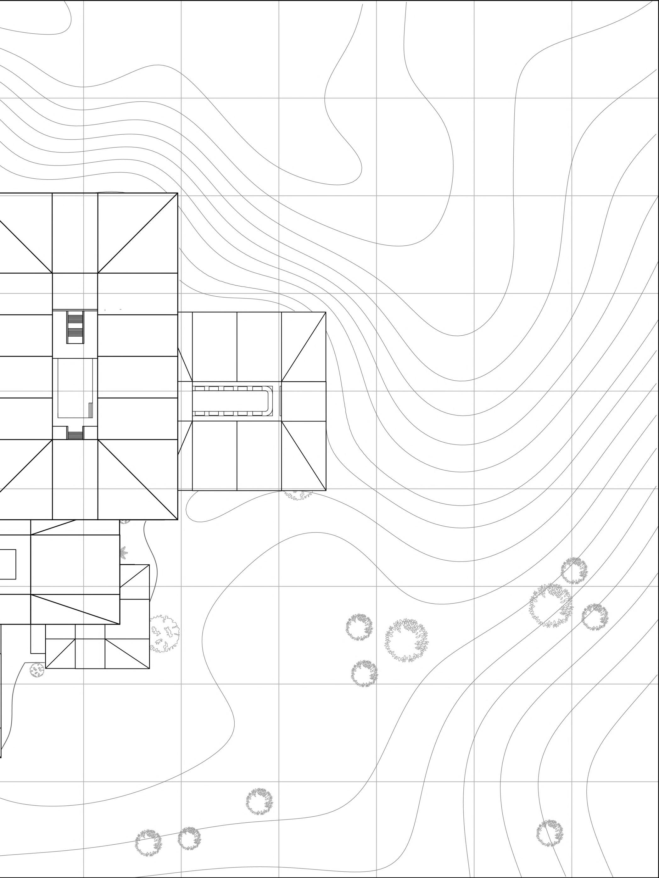
122 01 EntrancePath 02 EntranceLobby 03 WaitingArea 04 Entrance&PublicInformation 05 Security 06 PaintingWorkshop1 07 PaintingWorkshop2 08 TextilesWorkshop1 09 CentralCourtyard,Outdoor Workspace&ExhibitionSpace 10 ServiceAccess 11 MultipurposeAuditorium&Dining Hall 12 TextilesWorkshop2 13 ThermalLabyrinthAccess 14 CarpentryWorkshop 15 Dormitories 16 OutdoorCourtyard 17 OutdoorCourtyard 18 ServiceZone 0m3m9m 18m 27m 07 14 15 13 17 CHAPTER 6 _ FINAL DRAWINGS BARC0174 _ AAD1
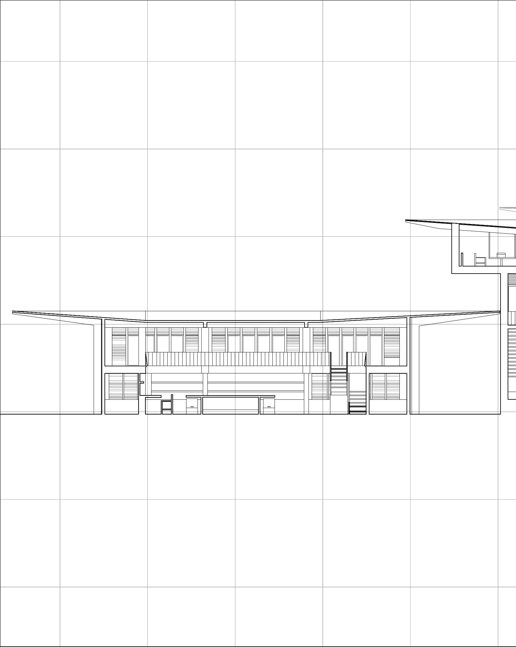
Long Section AA 1:125 @ A2 Section 6.09 01
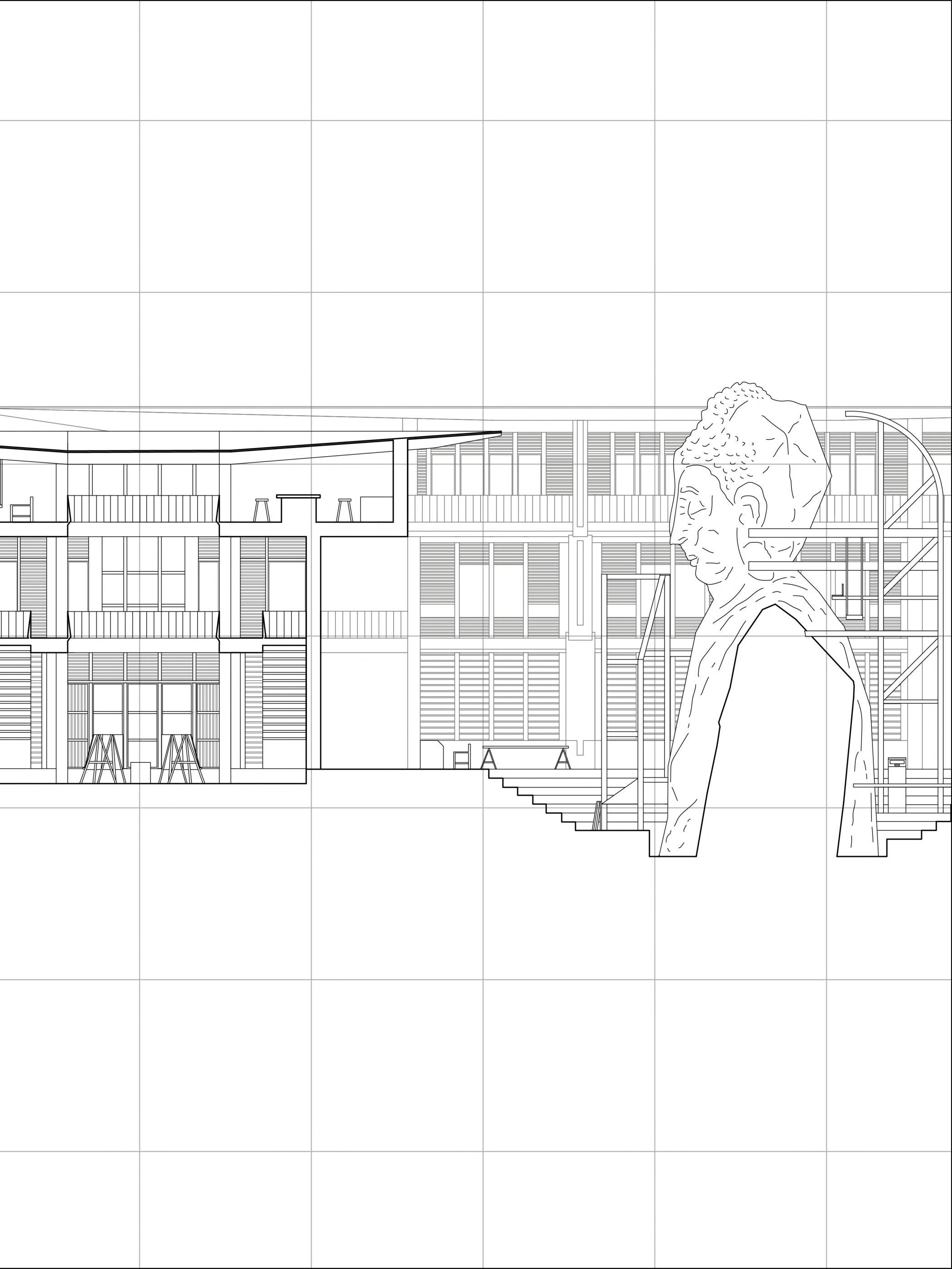
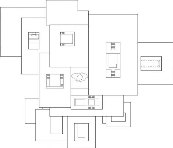
124 01 Security 02 PaintingWorkshop1 03 TextilesWorkshop1 04 CentralCourtyard,Outdoor Workspace&ExhibitionSpace 05 DemountableScaffoldingfor CentralBuddhaSculpture 0m1m3m 6m 12m 02 03 04 05 CHAPTER 6 _ FINAL DRAWINGS BARC0174 _ AAD1
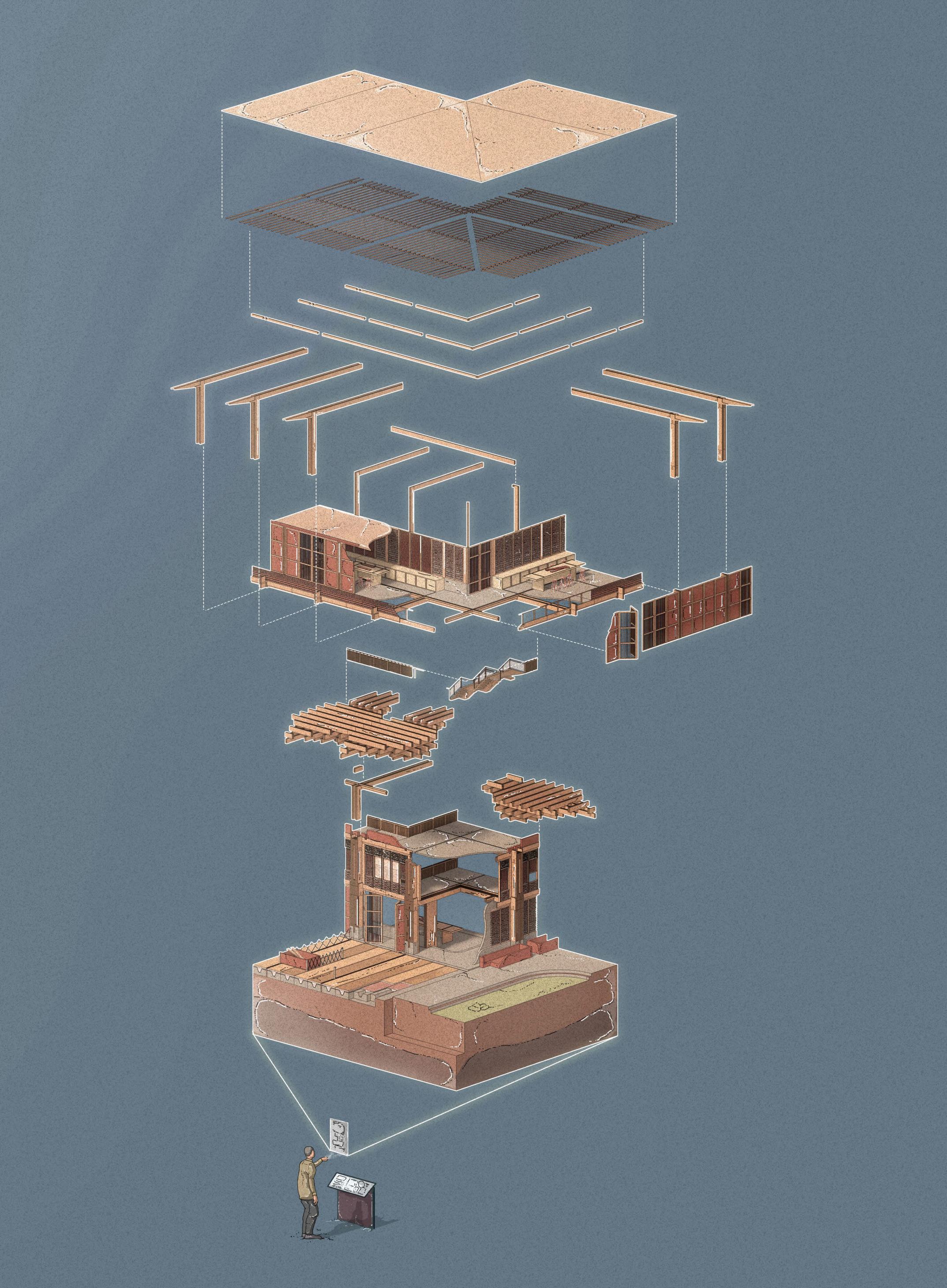
BIBLIOGRAPHY 07 Chapter 126 LHUENTSE SCHOOL OF CRAFTSBARC0174
/ Band,Thomas. Fondazione Gucci. Report,UniversityCollegeLondon,2020.p.11,37,50(NB.alsoreferencedinchapters2&5).
/ Boran,Daniel. Unorthodox Union. Report,UniversityCollegeLondon,2021.pp.19-21.https://issuu.com/unit14/docs/y5_01_daniel_boran.Accessed8 November2021.
/ Cendoya,Claudia.“BjarkeIngels(BIG)UnveilsSerpentineGalleryPavilion2016Project.” Metalocus, 25February,2016.https://www.metalocus.es/en/news/ bjarke-ingels-big-unveils-serpentine-gallery-pavilion-2016-project.Accessed15November2021.
/ Designboom.“prathaakathkhuniarchitectureofhimachalpradeshbyJayThakkarfromindia.”https://www.designboom.com/project/prathaa-kath-khuniarchitecture-of-himachal-pradesh/.Accessed8November2021(NB.alsoreferencedinchapter3).
/ Falkovskaia,Sonya.“Aseriesofboundaries.” The Wall and the Wave, University of Bath, 2018.https://www.sonyafalkovskaia.com/the-wall-and-thewave#11.Accessed15November2021(NB.alsoreferencedinchapter3).
/ Hicyilmaz,K.,J.K.Bothara,andM.Stephenson.“HousingReport:DhajjiDewari.” World Housing Encyclopedia, August2011.p.29.https://www.world-housing. net/WHEReports/wh100164.pdf.Accessed1November2021.
/ Hicyilmaz,K.,T.Wilcock,C.Izatt,J.da-Silva,andR.Langenbach.“SeismicPerformanceofDhajjiDewari.”2012.https://www.semanticscholar.org/paper/ Seismic-Performance-of-Dhajji-Dewari-Hicyilmaz-Wilcock/27d36636d0e8eb3601bf2f8efc97183de7f6d6e7.Accessed1November2021.
/ HughBroughtonArchitects.“HalleyVIBritishAntarcticResearchStation.”https://hbarchitects.co.uk/halley-vi-british-antarctic-research-station/.Accessed 15November2021.
/ Miller,DougJohn,andMarianneHanoun.“FutureCity–AnimationforWIRED:DougJohnMillerdiscussesfindingillustrationthrougharchitecture.”
Creative Lives in Progress, 7January2019.https://www.creativelivesinprogress.com/article/doug-john-miller-on-studying-architectureand-building-illustrative-worlds.Accessed7February2022(NB.alsoreferencedinchapters4&7).
/ Miller,DougJohn.“TheHarderkulmTransect.” Terra Incognita, Smout Allen, 2019.http://www.smoutallen.com/doug-miller-y5.Accessed7November2021 (NB.alsoreferencedinchapters3-6).
/ Morrison,Skye,andJayThakkar. Matra: Ways of Measuring Vernacular Built Forms of Himachal Pradesh. CEPTUniversity:SIDResearchCell,January2008.
https://www.researchgate.net/publication/307538994_Matra_Ways_of_Measuring_Vernacular_Built_Forms_of_Himachal_Pradesh.Accessed7 November2021.
/ Nagaraj,Pooja.“ModelExplorationofKath-khunihouse”.http://mansi-shah.weebly.com/student-work.html.Accessed7March2022.
/ Pandit,Sonakshi.“UrbanCa[r]talyser.” RIBA President’s Medals, 2020.http://www.presidentsmedals.com/Entry-52151.Accessed15November2021.
/ Reitsma,Manuela.“TheSecularHouse:AManualforPreservationandSeismicImprovementofVernacularStoneDwellingsinBhutan.” RIBA President’s Medals, 2021.http://www.presidentsmedals.com/Entry-17630.Accessed7February2022.
/ RetainingWallSolutions.“RetainingWallPriceComparison.”https://retainingwallsolutions.co.uk/retaining-wall-design/retaining-wall-price-comparison/. Accessed22November2021.
/ Sanadya,Megha,PallaviPrakash,ShivangiNishad,JatinKaur,andKomalSingh.“StudyofHimachalPradeshVernacular.” Slideshare, 3August,2018.https:// www.slideshare.net/MeghaSanadya/vernacular-architecture-of-himachal-pradesh-kath-kuni-architecture.Accessed25October2021.
/ Shah,Mansi,andJayThakkar.“TheHimalayanVernacular:Kath-KhuniArchitecture.” Sahapedia, 19September,2018.https://www.sahapedia.org/thehimalayan-vernacular-kath-khuni-architecture.Accessed25October2021.
/ BBCNews.“India-Chinadispute:Theborderrowexplainedin400words.” BBC News, 25January,2021.https://www.bbc.co.uk/news/world-asia-53062484. Accessed7February2022.
/ BhutanTravel.“Lhuentse.”https://www.bhutan.travel/destinations/lhuentse.Accessed7February2022.
/ BhutanTravel.“PoliticalSystem.”https://www.bhutan.travel/page/political-system.Accessed2May2022.
/ DrukAsia.“Bhutan13TraditionalArtsandCrafts(ZorigChusum).”24February,2021.https://www.drukasia.com/bhutan/bhutan-13-traditional-arts-andcrafts/.Accessed7March2022.
/ Goodman,Austen. Operation Klondike. Report,UniversityCollegeLondon,2020.p.39.
/ GoogleMaps.“LhuentseMap.”https://www.google.com/maps?q=lhuentse+map&bih=722&biw=1536&hl=en-US&um=1&ie=UTF-8&sa=X&ved=2ahUKEwizwP zwseH4AhUPa8AKHVDgBD4Q_AUoAXoECAEQAw.Accessed7February2022.
/ Jakhar,Pratik.“IndiaandChinaracetobuildalongadisputedfrontier.” BBC News, 30July,2020.https://www.bbc.co.uk/news/world-asia-53171124. Accessed7February2022.
/ NITIAayog.“SustainableDevelopmentintheIndianHimalayanRegion.”Lastupdated05July,2022.https://www.niti.gov.in/sustainable-development-indianhimalayan-region#:~:text=The%20Indian%20Himalayan%20Region%20is,)%2C%20stretching%20across%202500%20km
/ Norris,Ben. Nordicloop Nyhavn. Report,UniversityCollegeLondon,2021.p.13,21-22,44-48(NB.alsoreferencedinchapters4-5).
/ NSBBhutan.“DzongkhagMap.” Royal Government of Bhutan, Dzongkhag Administration, Lhuentse, 2022.http://www.lhuentse.gov.bt/dzongkhag-map. Accessed22November2021.
Bibliography Section 7.01
1
Chapter
Chapter 2
/ RajaguruIASAcademy.“InfrastructuredevelopmentintheHimalayanregion.”30August,2021.https://rajaguruiasacademy.com/p/infrastructuredevelopment-in-the-himalayan-region.Accessed7February2022.
/ RoyalGovernmentofBhutan. Bhutan Building Regulation 2018. DepartmentofHumanSettlement,MinistryofWorksandHumanSettlement,Royal GovernmentofBhutan,April2018.https://bhutan.eregulations.org/media/Final-Buidling-Regulation__2018.pdf.Accessed6June2022.
/ RoyalGovernmentofBhutan. Twelfth Five Year Plan, 2018-2023: Volume 1: Main Document. Thimphu,Bhutan:GrossNationalHappiness Commission,RoyalGovernmentofBhutan,2019.https://www.gnhc.gov.bt/en/wp-content/uploads/2019/05/TWELVE-FIVE-YEAR-WEBVERSION.pdf.Accessed27June2022.
/ Rubbra,Naomi. New Citizens’ House. Report,UniversityCollegeLondon,2018.p.9,22-32,34-35,38-39(NB.alsoreferencedinchapters4-5).
/ TheEconomist.“Fantasyfrontiers,Graphicdetail:Indian,PakistaniandChineseborderdisputes.” The Economist, 8February,2012.https://www. economist.com/graphic-detail/2012/02/08/fantasy-frontiers.Accessed22November2021.
/ Upadhyaya,Bhim,andRoyalGovernmentofBhutan. Bhutan Building Rules 2002. DepartmentofUrbanDevelopment&Housing,Ministryof Communications.pp.1-31.https://www.slideshare.net/BhimUpadhyaya/bhutan-buildingrules2002.Accessed27June2022.
/ Wikipedia.2022.“DepartmentofForestsandParkServicesofBhutan.” Wikimedia Foundation. Lastedited14April,2022.https://en.wikipedia.org/ wiki/Department_of_Forests_and_Park_Services_of_Bhutan
/ Li,Shaokang. An Archive of the Ciudad Perdida. Report,UniversityCollegeLondon,2020.pp.12-14.https://issuu.com/shaokangli13/docs/ compressed_portfolio_levi_shaokang_li_unnit18.Accessed7February2022(NB.alsoreferencedinchapter4).
/ Sen,Arinjoy(@arinjoy_sen).“PerspectivesonRadicalCommoning.AManifestoforanAlternativeModeofProduction.” Instagram, 16May,2020. https://www.instagram.com/p/CAPrlfYpbH6/.Accessed7March2022(NB.alsoreferencedinchapters4-5).
/ Carroll,Sean.“WhatisaTruss?” Degree Tutors, 5January,2019.https://www.degreetutors.com/what-is-a-truss/.Accessed2May2022(NB. alsoreferencedinchapter5).
/ Chard,Andrew. The Oasis: Salton Sea Elementary School. Report,UniversityCollegeLondon,2018.pp.32-43(NB.alsoreferencedinchapter5).
/ Fernandez,Paddy. Mitsubishi Mariculture. Report,UniversityCollegeLondon,2018.p.52,58-59.https://issuu.com/unit14/docs/_pf.Accessed7 March2022.
/ Gross,Holger. Glulam Handbook Volume 1. Stockholm,Sweden:FöreningenSverigesSkogsindustrier–TheSwedishForestIndustriesFederation, 2013.p.19.https://www.woodcampus.co.uk/wp-content/uploads/2019/05/GLU_HAND_VOLUME-1.pdf.Accessed8November2021.
/ Gunther,RG.“woodworkingmachinery.” Sketchup 3D Warehouse. https://3dwarehouse.sketchup.com/model/0f74fcf4-f447-41e2-80dd23714982cb11/woodworking-machinery?hl=es.Accessed2May2022.
/ James,Connor. Monastic Outpost. Report,UniversityCollegeLondon,2020.pp.29-30.https://issuu.com/unit14/docs/y4_01_connor_james_1. Accessed7February2022.
/ Moss,Ryan. Hong Kong Parliament. Report,UniversityCollegeLondon,2021.p.23-25,28-32.
/ Pons-Poblet,JosepMaria.“TheVierendeelTruss:PastandPresentofanInnovativeTypology.” Arquitetura Revista 15,no.1,2019.pp.193-211. https://www.redalyc.org/journal/1936/193660402011/html/.Accessed6June2022.
/ Sen,Arinjoy. Productive Insurgence. Report,UniversityCollegeLondon,2020.p.43,62-63.https://issuu.com/arinjoysen/docs/productive_ insurgence_asreduced2.Accessed7February2022.
/ Valle,JamesDella.“BetweentheFrame.” Bartlett School of Architecture Summer Show 2020, 2020.https://summer2020.bartlettarchucl.com/ ug8/year3-james-della-valle.Accessed8November2021.
/ Walker,Dominic. The Monastic School of Architecture. Report,UniversityCollegeLondon,2018.p.30.
/ Bonsor,Kevin.“HowHydropowerPlantsWork.” Howstuffworks. https://science.howstuffworks.com/environmental/energy/hydropower-plant1.htm. Accessed2May2022.
/ Forward,Michael. The Arctic Tap. Report,UniversityCollegeLondon,2019.p.44. / Leggatt,Tom.“Section3.5:ADecentralisedEnergyNetwork.” Generation Montagna, Incomplete, Smout Allen, 2020.http://www.smoutallen.com/ tom-leggett-y4.Accessed2May2022.
128 CHAPTER 7 _ BIBLIOGRAPHY BARC0174 _ AAD1
Chapter 3
Chapter 5
Chapter 4
Section 7.01
Chapter 5 (cont.)
/ Lesikar,Bruce.“OnsiteWastewaterTreatmentSystems:SepticTank/SoiAbsorptionField.” Texas A&M Agrilife Extension. https://agrilifeextension. tamu.edu/library/water/onsite-wastewater-treatment-systems-septic-tank-soil-absorption-field/.Accessed2May2022.
/ Meteoblue.“Simulatedhistoricalclimate&weatherdataforLhuentse.”https://www.meteoblue.com/en/weather/historyclimate/climatemodelled/lhuentse_ bhutan_1252526.Accessed6June2022.
/ Miller,DougJohn.“Mapped.” National Reserve, Smout Allen, 2018.http://www.smoutallen.com/douglas-miller-y4.Accessed2May2022.
/ Přikryl,Richard,ÁkosTörök,MagdaliniTheodoridou,MiguelGomez-Heras,andKarelMiskovsky.“Geomaterialsinconstructionandtheirsustainability: Understandingtheirroleinmodernsociety.” Geological Society London Special Publications 416,no.1,February2016.pp.1-22.https://www. researchgate.net/figure/Embodied-carbon-associated-with-stone-cement-concrete-and-brick-data-from-Hammond_fig2_298070425.Accessed2 May2022.
/ Wikipedia.2022.“EnergyinBhutan.” Wikimedia Foundation. Lastedited20May,2022.https://en.wikipedia.org/wiki/Energy_in_Bhutan
Bibliography (cont.)
130 CHAPTER 7 _ BIBLIOGRAPHY BARC0174 _ AAD1
Pleasenotethatallofthefollowingreferenceshavebeenusedasprecedentsforgraphicsorfurtherinformationforimagesproducedbytheauthorofthisreport, unlessstatedinthesuffixofthefollowingreferences,inbrackets-NB.originalsourceimageshowninthisreport.
Chapter 1
1.01A M.V.DZanden,“Cornerconnectionincasestudybuilding,”in Assessment of the seismic performance and sustainability of the Kath-Khuni building style in the Indian Himalaya, in Semantics Scholar, 2018.p.29,https://www.semanticscholar.org/paper/Assessment-of-the-seismic-performanceand-of-the-in-Zanden/999f7888c12adcd2ed02ded0c3b1254869b8b7d6/figure/17.Accessed8November2021(NB.originalsourceimageshownin thisreport).
1.02A Zanden,“AssessmentoftheseismicperformanceandsustainabilityoftheKath-KhunibuildingstyleintheIndianHimalaya,”p.56.
1.02B-D SkyeMorrison,andJayThakkar, Matra: Ways of Measuring Vernacular Built Forms of Himachal Pradesh, CEPTUniversity:SIDResearchCell,January 2008,p.43,59,156,https://www.researchgate.net/publication/307538994_Matra_Ways_of_Measuring_Vernacular_Built_Forms_of_Himachal_ Pradesh.Accessed7November2021.
1.03A-D K.Hicyilmaz,T.Wilcock,C.Izatt,J.da-Silva,andR.Langenbach,“SeismicPerformanceofDhajjiDewari,”2012,https://www.semanticscholar.org/ paper/Seismic-Performance-of-Dhajji-Dewari-Hicyilmaz-Wilcock/27d36636d0e8eb3601bf2f8efc97183de7f6d6e7.Accessed1November2021.
1.04A K.Hicyilmaz,J.K.Bothara,andM.Stephenson,“HousingReport:DhajjiDewari,”in World Housing Encyclopedia, 2011.p.29,https://www.worldhousing.net/WHEReports/wh100164.pdf.Accessed1November2021.
1.05A PoojaNagaraj,“ModelExplorationofKath-khunihouse,”http://mansi-shah.weebly.com/student-work.html.Accessed7March2022.
1.06A DavidSouthwood,andAJBuildingsLibrary,“HalleyVIAntarcticResearchStation,” AJ Buildings Library, https://www.ajbuildingslibrary.co.uk/ projects/display/id/934.Accessed22November2021(NB.usedasreferencefortoptwoimagesandbottomrightimage).
1.08A DanielBoran, Unorthodox Union, Report,UniversityCollegeLondon,2021,pp.20-21,https://issuu.com/unit14/docs/y5_01_daniel_boran.Accessed8 November2021.
1.09A Ibid,p.19.
1.11A RetainingWallSolutions,“RetainingWallPriceComparison,”https://retainingwallsolutions.co.uk/retaining-wall-design/retaining-wall-pricecomparison/.Accessed22November2021.
1.11B SonakshiPandit,“UrbanCa[r]talyser,” RIBA President’s Medals, 2020,http://www.presidentsmedals.com/Entry-52151.Accessed15November2021.
1.16A-B SonyaFalkovskaia,“Aseriesofboundaries,” The Wall and the Wave, University of Bath, 2018,https://www.sonyafalkovskaia.com/the-wall-and-thewave#11.Accessed15November2021.
1.18A Pandit,“UrbanCa[r]talyser.”
1.18B RetainingWallSolutions,“RetainingWallPriceComparison.”
2.01A
DavidZurick,JulsunPacheco,BasantaShrestha,andBirendraBajracharya, Atlas of the Himalayas, p.27,70,Kathmandu,Nepal:InternationalCentre forIntegratedMountainDevelopment(ICIMOD),2005.
2.01B Zuricketal., Atlas of the Himalayas, p.53.
2.01C Ibid,p.8,10,13,15,20,28,60(NB.originalsourceimagesshowninthisreport).
2.03A TheEconomist,“Currentboundaries,” Fantasy frontiers, Graphic detail: Indian, Pakistani and Chinese border disputes, 2012,https://www.economist. com/graphic-detail/2012/02/08/fantasy-frontiers.Accessed22November2021.
2.04A Zuricketal., Atlas of the Himalayas, p.27.
2.05A Ibid,p.21,65(NB.originalsourceimagesshowninthisreport–twophotosonright;alsousedasreferenceformaponleft).
2.07A muddum27.“LhuentseDzong.”Photograph. Flickr. https://flickr.com/photos/57615250@N00/3355307329.Accessed16February2022(NB.original sourceimageshowninthisreport–topimage);BhutanBroadcastingService.“LhuentseDistrictCourt.”Photograph.http://www.bbs.bt/ news/?p=81252.Accessed16February2022(NB.originalsourceimageshowninthisreport–bottomimage).
2.08A NaomiRubbra, New Citizens’ House, Report,UniversityCollegeLondon,2018,p.9.
2.08B ThomasBand, Fondazione Gucci, Report,UniversityCollegeLondon,2020,p.11.
2.09A Vector-Images.com.“EmblemofBhutan—usedbytheParliamentofBhutan,firstestablishedin2007.”Digitalimage.2December2005.https:// commons.wikimedia.org/wiki/File:Emblem_of_Bhutan.svg.Accessed6June2022.(NB.originalsourceimageshowninthisreport-emblem).
2.09B BhimUpadhyaya,andRoyalGovernmentofBhutan,“BhutanBuildingRules2002,”in Bhutan Building Rules 2002,DepartmentofUrbanDevelopment &Housing,MinistryofCommunications,p.1,https://www.slideshare.net/BhimUpadhyaya/bhutan-buildingrules2002.Accessed27June2022(NB. originalsourceimageshowninthisreport–onlefthandside);RoyalGovernmentofBhutan,”TwelfthFiveYearPlan2018-2023,” Twelfth Five Year Plan, 2018-2023: Volume 1: Main Document, Thimphu,Bhutan:GrossNationalHappinessCommission,RoyalGovernmentofBhutan,2019,p.1,https:// www.gnhc.gov.bt/en/wp-content/uploads/2019/05/TWELVE-FIVE-YEAR-WEB-VERSION.pdf.Accessed27June2022(NB.originalsourceimage showninthisreport–onrighthandside).
Figures
7.02
Section
Chapter 2
2.09C DepartmentofForestsandParkServices,MinistryofAgricultureandForests,RoyalGovernmentofBhutan.“DOFPSBhutanLogo.”Digital image.https://www.dofps.gov.bt/.Accessed6June2022(NB.originalsourceimageshowninthisreport-emblem).
2.09D BenNorris, Nordicloop Nyhavn, Report,UniversityCollegeLondon,2021,p.48.
2.09E SherubtseCollege(@sherubtsecol).“SherubtseCollegeKanglunglogo.” Twitter. https://mobile.twitter.com/sherubtsecol/photo.Accessed 27June2022(NB.originalsourceimageshowninthisreport-emblem);
RoyalUniversityofBhutan.“RoyalUniversityofBhutanlogo.”Digitalimage.https://www.rub.edu.bt/images/rub/Key-Documents/AnnualReports/annual_report_2016.pdf.Accessed27June2022(NB.originalsourceimageshowninthisreport-emblem);
BhutanCollegeofScienceandTechnology.“BhutanCollegeofScienceandTechnologylogo.”Digitalimage.https://cst.edu.bt/index.php/ en/.Accessed27June2022(NB.originalsourceimageshowninthisreport-emblem);
KhesarGyalpoUniversityofMedicalSciencesofBhutan,RoyalGovernmentofBhutan.“KGUMSBlogo.”Digitalimage.https://www.kgumsb. edu.bt/?page_id=3815.Accessed27June2022(NB.originalsourceimageshowninthisreport-emblem);
RoyalUniversityofBhutan,CollegeofNaturalResources.“CollegeofNaturalResourceslogo.”Digitalimage.https://www.cnr.edu.bt/. Accessed27June2022(NB.originalsourceimageshowninthisreport-emblem);
ParoCollegeofEducation.“ParoCollegeofEducationlogo.”Digitalimage.https://www.pce.edu.bt/.Accessed27June2022(NB.original sourceimageshowninthisreport-emblem);
RoyalThimphuCollege.“RoyalThimphuCollegelogo.”Digitalimage.https://www.rtc.bt/.Accessed27June2022(NB.originalsource imageshowninthisreport-emblem);
JigmeNamgyelEngineeringCollege.“JigmeNamgyelEngineeringCollegelogo.”Digitalimage. https://www.jnec.edu.bt/en/.Accessed27 June2022(NB.originalsourceimageshowninthisreport-emblem).
3.03A Pegenaute,Pedro.“TsingpuYangzhuoRetreat/Neri&HuDesignandResearchOffice.”Photograph. ArchDaily. https://www.archdaily. com/888969/the-walled-tsingpu-yangzhou-retreat-neri-and-hu-design-and-research-office.Accessed27June2022(NB.originalsource imageshowninthisreport–bottomleftimage).
3.03B Chen,Hao.“Aerialview:AlilaYangshuoHotel/VectorArchitects.”Photograph. ArchDaily. https://www.archdaily.com/928950/alilayangshuo-vector-architects.Accessed27June2022(NB.originalsourceimageshowninthisreport–bottomrightimage).
3.05A Falkovskaia,“Aseriesofboundaries.”
3.06A ShaokangLi, An Archive of the Ciudad Perdida, Report,UniversityCollegeLondon,2020,p.12,https://issuu.com/shaokangli13/docs/ compressed_portfolio_levi_shaokang_li_unnit18.Accessed7February2022.
3.07A Ibid,p.14.
3.08A Zanden,“AssessmentoftheseismicperformanceandsustainabilityoftheKath-KhunibuildingstyleintheIndianHimalaya,”p.56.
3.08B Li, An Archive of the Ciudad Perdida, pp.12-14.
3.08C DougJohnMiller,“TheHarderkulmTransect,” Terra Incognita, Smout Allen, 2019,http://www.smoutallen.com/doug-miller-y5.Accessed7 November2021(NB.firstimageusedasreferencefor‘SitePlan’).
4.05A DougJohnMiller,andMarianneHanoun,“FutureCity–AnimationforWIRED:DougJohnMillerdiscussesfindingillustrationthrough architecture.” Creative Lives in Progress, 7January2019,https://www.creativelivesinprogress.com/article/doug-john-miller-on-studyingarchitecture-and-building-illustrative-worlds.Accessed7February2022(NB.usedasreferenceforperson,styleandbluecolour).
4.05B Rubbra, New Citizens’ House, pp.25-26.
4.05C-E RyanMoss, Hong Kong Parliament, Report,UniversityCollegeLondon,2021,pp.23-24.
4.06A Ibid,p.25.
4.07A JamesDellaValle,“BetweentheFrame,” Bartlett School of Architecture Summer Show 2020, 2020,https://summer2020.bartlettarchucl. com/ug8/year3-james-della-valle.Accessed8November2021.
4.07B ConnorJames, Monastic Outpost, Report,UniversityCollegeLondon,2020,pp.29-30,https://issuu.com/unit14/docs/y4_01_connor_ james_1.Accessed7February2022.
4.08A HolgerGross, Glulam Handbook Volume 1, Stockholm,Sweden:FöreningenSverigesSkogsindustrier–TheSwedishForestIndustries Federation,2013,p.19,https://www.woodcampus.co.uk/wp-content/uploads/2019/05/GLU_HAND_VOLUME-1.pdf.Accessed8November 2021;James, Monastic Outpost, p.30(NB.usedasreferenceforbottomdiagrams).
4.09A DouglasYang,Re-ImagineChineseTimberFrame,Report,UniversityCollegeLondon,2020,pp.56-63,https://issuu.com/unit14/docs/ y5_01_douglas_yang.Accessed7February2022.
132 CHAPTER 7 _ BIBLIOGRAPHY BARC0174 _ AAD1
Chapter 3
Chapter 4
Section 7.02
Chapter 4 (cont.)
4.09B TakumiOtaPhotography,andArchDaily,“YusuharaWoodenBridgeMuseum/KengoKuma&Associates,” ArchDaily, 16February,2012, https://www.archdaily.com/199906/yusuhara-wooden-bridge-museum-kengo-kuma-associates.Accessed7March2022.
4.10A, D Miller,“TheHarderkulmTransect”(NB.firstimageusedasreferencefor‘CarpentryWorkshopNativeUser&Toolkit’,‘SitePlan’andcentral image.Alsousedasreferencefortrees).
4.10B Rubbra, New Citizens’ House, p.31.
4.10C Li, An Archive of the Ciudad Perdida, pp.12-14.
4.11A Rubbra, New Citizens’ House, p.26,28.
4.12A, C-D ArinjoySen, Productive Insurgence, Report,UniversityCollegeLondon,2020,p.43,https://issuu.com/arinjoysen/docs/productive_ insurgence_asreduced2.Accessed7February2022.
4.12B Rubbra, New Citizens’ House, p.22.
4.13A DominicWalker, The Monastic School of Architecture, Report,UniversityCollegeLondon,2018,p.30.
4.14A ArinjoySen(@arinjoy_sen),“PerspectivesonRadicalCommoning.AManifestoforanAlternativeModeofProduction,” Instagram, 16May,2020, https://www.instagram.com/p/CAPrlfYpbH6/.Accessed7March2022.
4.14B Moss, Hong Kong Parliament, p.32.
4.14C Sen, Productive Insurgence, pp.62-63.
4.14D PaddyFernandez, Mitsubishi Mariculture, Report,UniversityCollegeLondon,2018,pp.58-59,https://issuu.com/unit14/docs/_pf.Accessed7 March2022.
4.15A-B Rubbra, New Citizens’ House, p.21,32.
4.15C-E Moss, Hong Kong Parliament, pp.28-29,31.
4.15F AnnabelleTan,“Section3.03–3.04:RenewableEnergySystemsandWaterSystems,” The River, Restoration and Its Rituals, Uncommon Ground, Smout Allen, 2021,http://www.smoutallen.com/annabelle-tan-y4.Accessed4April2022.
4.15G RGGunther,“woodworkingmachinery,” Sketchup 3D Warehouse, https://3dwarehouse.sketchup.com/model/0f74fcf4-f447-41e2-80dd23714982cb11/woodworking-machinery?hl=es.Accessed2May2022.
Chapter 5
5.00A Meteoblue,“Simulatedhistoricalclimate&weatherdataforLhuentse,”https://www.meteoblue.com/en/weather/historyclimate/climatemodelled/ lhuentse_bhutan_1252526.Accessed6June2022.
5.01A, F Rubbra, New Citizens’ House, pp.34-35,38.
5.01B-E, H-I Tan,“Section3.03–3.04:RenewableEnergySystemsandWaterSystems.”
5.01G AndrewChard, The Oasis: Salton Sea Elementary School, Report,UniversityCollegeLondon,2018,p.32.
5.01I BruceLesikar,“OnsiteWastewaterTreatmentSystems:SepticTank/SoiAbsorptionField,” Texas A&M Agrilife Extension, https:// agrilifeextension.tamu.edu/library/water/onsite-wastewater-treatment-systems-septic-tank-soil-absorption-field/.Accessed2May 2022.
5.02A Wikipedia.2022.“Bhutanelectricityproduction.” Wikimedia Foundation. Lastedited20May,2022.https://en.wikipedia.org/wiki/Energy_in_ Bhutan#/media/File:Bhutan_electricity_production.svg
5.02B-D TomLeggatt,“Section3.5:ADecentralisedEnergyNetwork,” Generation Montagna, Incomplete, Smout Allen, 2020,http://www.smoutallen. com/tom-leggett-y4.Accessed2May2022.
5.02D KevinBonsor,“HowHydropowerPlantsWork,” Howstuffworks, https://science.howstuffworks.com/environmental/energy/hydropowerplant1.htm.Accessed2May2022.
5.03A, C-D Chard, The Oasis: Salton Sea Elementary School, p.39,41,43.
5.03B Band, Fondazione Gucci, p.37.
5.04A Sen,“PerspectivesonRadicalCommoning.”
5.04B Weather2visit.“Averagedaytimetemperature.”https://www.weather2visit.com/asia/bhutan/lhuentse.htm.Accessed2May2022.
5.04C MichaelForward, The Arctic Tap, Report,UniversityCollegeLondon,2019,p.44.
5.04D Rubbra, New Citizens’ House, pp.38-39.
5.05A DougJohnMiller,“Mapped,” National Reserve, Smout Allen, 2018,http://www.smoutallen.com/douglas-miller-y4.Accessed2May2022 (NB.sixthimageusedasreferenceforgraphics).
5.05B-C Chard, The Oasis: Salton Sea Elementary School, p.42.
5.06A Norris, Nordicloop Nyhavn, p.21.
5.07A Ibid,p.22.
Figures (cont.)
134 CHAPTER 7 _ BIBLIOGRAPHY BARC0174 _ AAD1
All work produced by Unit 14
Unit book design by Charlie Harriswww.bartlett.ucl.ac.uk/architecture
Copyright 2021
The Bartlett School of Architecture, UCL All rights reserved.
No part of this publication may be reproduced or transmited in any form or by any means, electronic or mechanical, including photocopy, recording or any information storage and retreival system without permission in writing from the publisher.

-
@unit14_ucl UNIT
SPATIAL TECTONIC 2022

PG14 is a test bed for architectural exploration and innovation, examining the role of the architect in an environment of continuous change. We are in search of the new: leveraging technologies, workflows and modes of production seen in disciplines outside our own. We test ideas systematically by means of digital as well as physical drawings, models and prototypes. Our work evolves around technological speculation with a research-driven core, generating momentum through the astute synthesis of both. Our propositions are ultimately made through the design of buildings and in-depth consideration of structural formation and tectonic constituents. This, coupled with a strong research ethos, generates new and unprecedented, viable and spectacular proposals.
The focus of this year’s work evolved around the concept of ‘Spatial Tectonic’. This term describes architectural space as a result of the highest degree of synthesis of all underlying principles. Constructional logic, spatial innovation, typological organisation, and environmental and structural performance are all negotiated in an iterative process driven by architectural investigation. These inherent principles of organisational intelligence can be observed in both biotic and abiotic systems, in all spatial arrangements where it is critical for the overall performance of any developed order. Ultimately such principles suggest that the arrangement of constituents provides intelligence as well as advantage to the whole.
Through a deep understanding of architectural ingredients, students generated highly developed architectural systems in which spatial organisation arose as a result of sets of mutual interactions. These interactions were understood through targeted iterations of spatial models, uncovering logical links while generating ambitious and speculative arrangements. Sequential testing and the enriching of abstract yet architectural systems were the basis of architectural form - communicating the relationship of all logical dependencies, roles and performances within the system.

UNIT 14 @unit14_ucl All work produced by Unit 14 Unit book design by Charlie Harriswww.bartlett.ucl.ac.uk/architecture Copyright 2021 The Bartlett School of Architecture, UCL All rights reserved.No part of this publication may be reproduced or transmitted in any form or by any means, electronic or mechanical, including photocopy, recording or any information storage and retreival system without permission in writing from the publisher.
Thanks to: ARUP, ALA, DKFS, knippershelbig, RSHP, HASSELL, Seth Stein Architects, ZHA, Expedition Engineering
