THE CARPENTER’S GUILDHOUSE
A PROTOTYPE FOR INTERROGATING THE GERMAN TIMBER FRAME
 LÜBECK, GERMANY
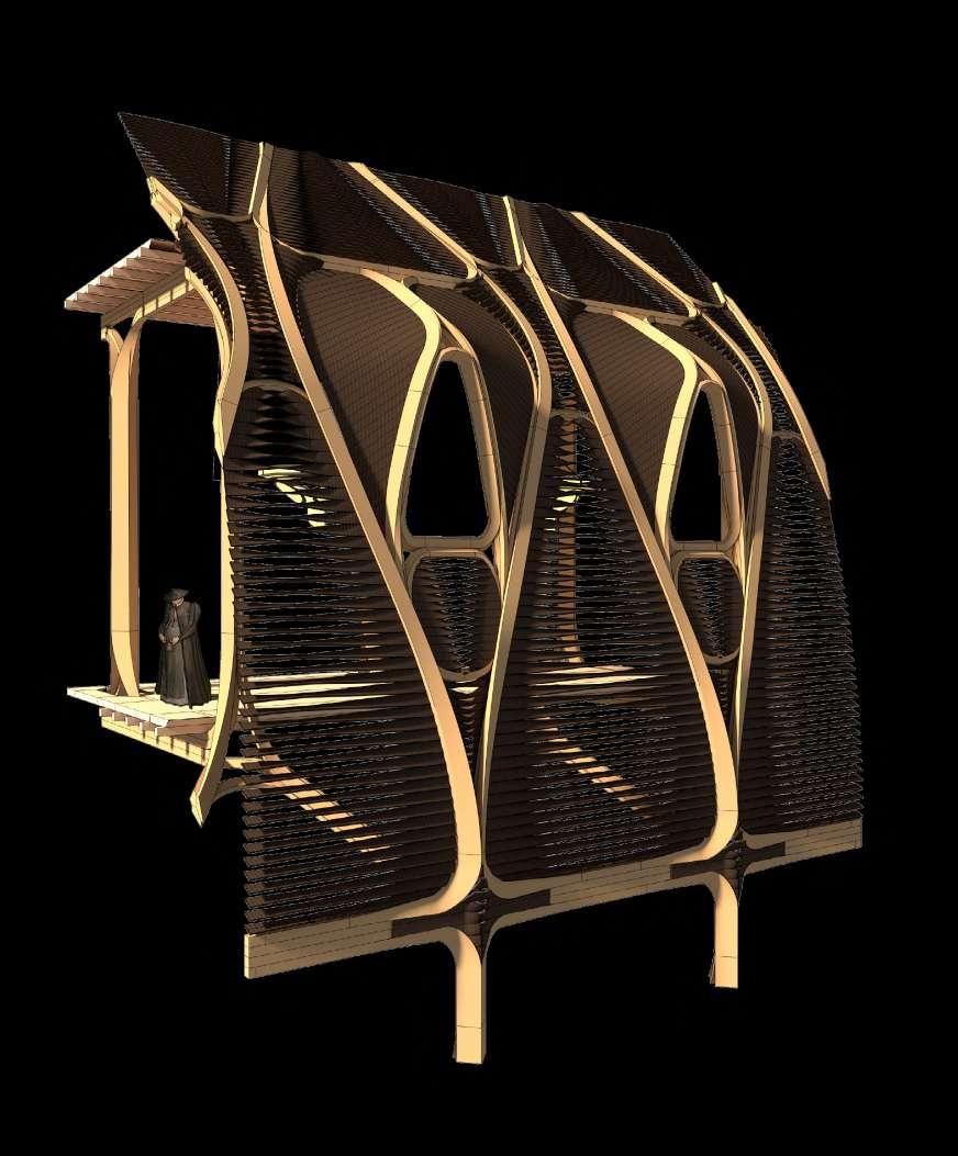
The project imagines a future guildhouse for timber framers (Zimmerleute), sited in the northern German city of Lübeck, building on the history of this dead but formerly valuable typology. Working from a research phase investigating the possibilities of a complex series of nodal glulam components, the project speculates on the development of glulam fabrication technologies specifically with a focus on connection strategies (which typically govern the performance of timber structures). The building is made up of a series of prefabricated components with nodal connections built in which can be assembled on site. The project looks to leverage the expressive possibilities of the system, treading the line between referencing the traditions of craftsperson organisation in Germany and a future typology influenced by digital possibilities.

SEBASTIAN BIRCH YEAR 4
@unit14_ucl Y4 SB
Project statement:
The project imagines a future guildhouse for timber framers (Zimmerleute), sited in the northern German city of Lübeck, building on the history of this dead but formerly valuable typology. Working from a research phase investigating the possibilities of a complex series of nodal glulam components, the project speculates on the development of glulam fabrication technologies specifically with a focus on connection strategies (which typically govern the performance of timber structures). The building is made up of a series of prefabricated components with nodal connections built in which can be assembled on site. The project looks to leverage the expressive possibilities of the system, treading the line between referencing the traditions of craftsperson organisation in Germany and a future typology influenced by digital possibilities.
2
PG14 2021 / 2022
Sebastian Birch
3 section 1 design research
1. Natural taper of spruce pole allows a tighter bend at the top of the curve

Hooke Park Training Centre by ABK, Buro Happold, Frei Otto in Dorset, England
Structural Performance: Use of Deformability
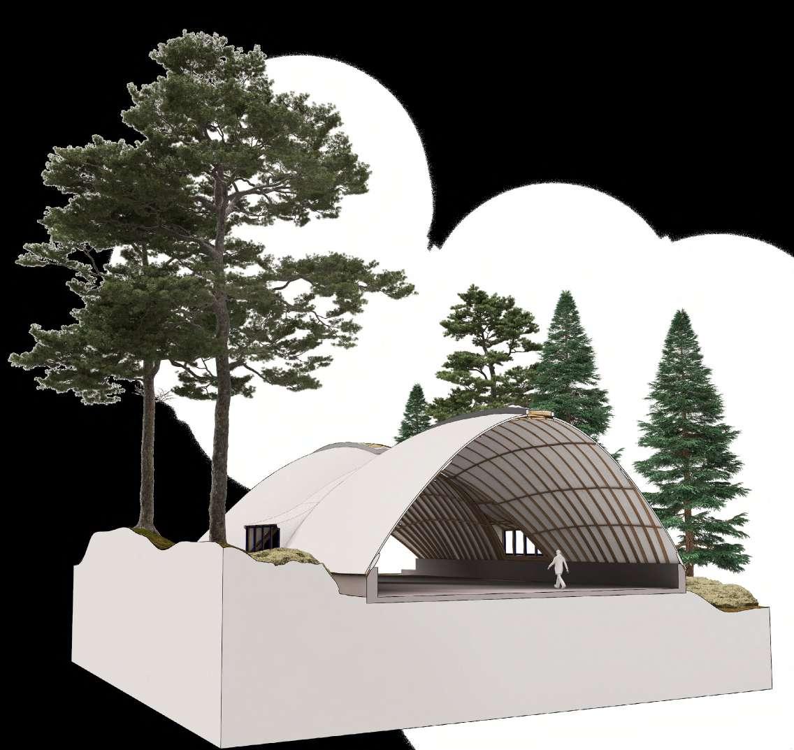
The workshop building at Hooke Park demonstrates a novel application for green roundwood thinnings, a waste product of forest management. The concept was to use the wood in a prestressed condtion as flexible poles, bent while the wood was still wet and deformable. The form of the roof shell holds the members in their prestressed position, mitigating the effects of creep.
4
1.
3.
2.
2.
3.
1.
1. Concrete footing
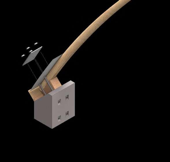
2. Steel plate and strap connection secures roundwood of varying sizes
3. Spruce pole bent to shape when green
2. Bolted lap/scarf joint secures bent timbers in pre-stressed position
3. Fibreglass wrapping adds final security to joint
Hooke Park Training Centre
Assembly Strategy: Simple Components
Novel jointing and assembly methods were developed for using this underused material. Conceived as a kit of components slotting together, poles were bent into place using the foundation as a jig. Keeping the poles as roundwood meant that knot defects did not affect cold bending due to fibre continuity. The PVC coated membrane, nailed to arches, acts as a further tensile element in the crossbraced system.


5
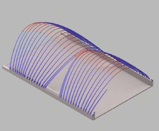
Green spruce poles fixed to upstand Poles cold bent into ‘pre-stressed’ form purlins and crown elements maintain shell
PVC membrane acts as tensile element in shell system
by ABK, Buro Happold, Frei Otto in Dorset, England
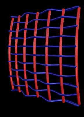
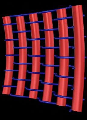
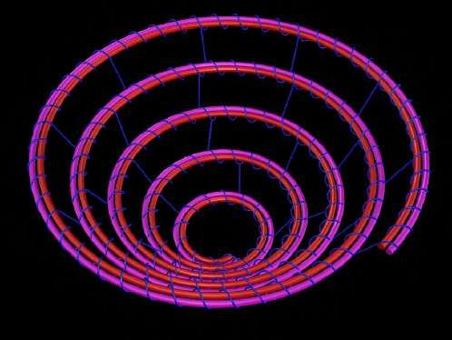
Basketry
Initial Investigation
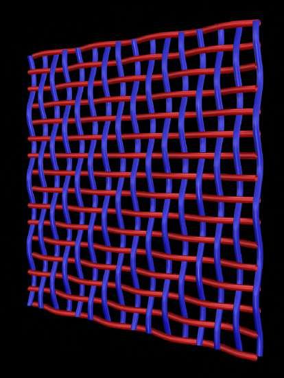
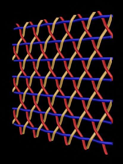
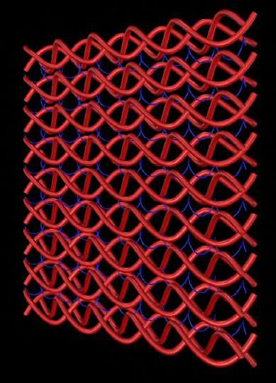
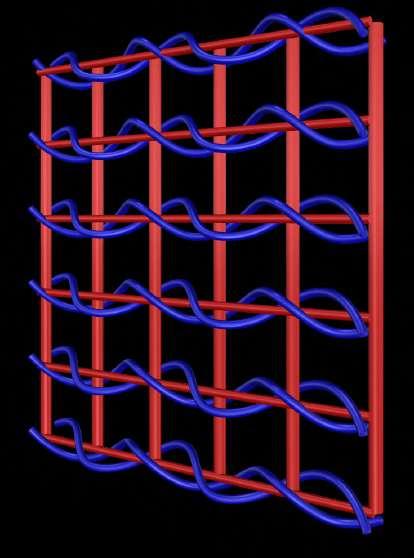
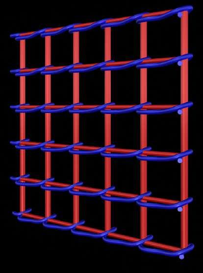
Basketry investigated as approach for making interwoven structures using deformable but rigid material. Different approaches can be taken for holding the material in its stressed form. Generally members restrain each other through wrapping, tying or interlocking. There are 3 main kinds of basket construction: coiled, frame/weave (both with primary and secondary members) and matted/plaited (homogeneous).
Methods to be adapted (artefacts)
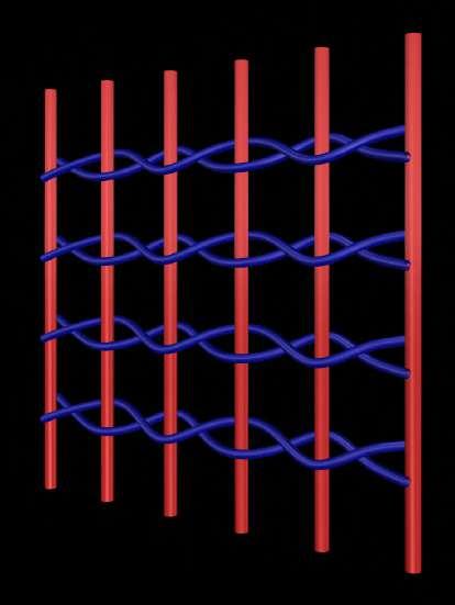
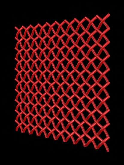
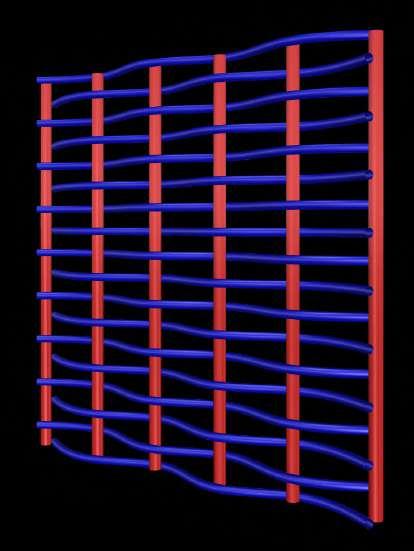
Out of the series of manufacture techniques 3 were judged as containing potential for an architectural application for building with a deformable member: 01. frame and weave construction to introduce heirarchy into a structure 02. tri-axial weaving which can be densified and allows for a surface condition 03. splitting of members allows for varied conditions of overlap.


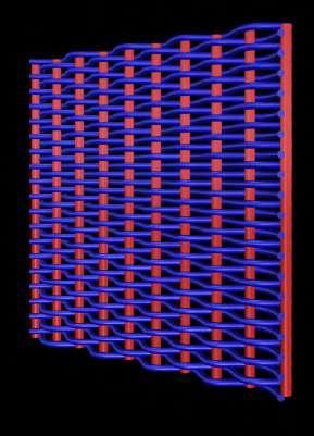



6 7 1.0 Coil Construction
2.0 Frame and Weave Construction (Lattice)
1.1 Single coil
2.1 Braid and sewn 2.2 Single twine
2.3 Double twined 2.4 Wrapped intersections
1.2 Double coil
1.3 Twill effect
Manufacture
3.1
3.3
3.4 tri-axial
2.1
2.2
2.3
2.4 Diagonal
2.3.1 Variable density 2.3.2 Variable curvature 2.3.2 Variable member thickness
Perpendicular 3.2 Oblique
Twill (shifted intersections)
weave
Wrapped intersection
Twined
Alternating (wickerwork)
members added
3.0 Plaitted Construction
2.1 Frame and Weave Construction (Parallels)
Hooke Park Training Centre
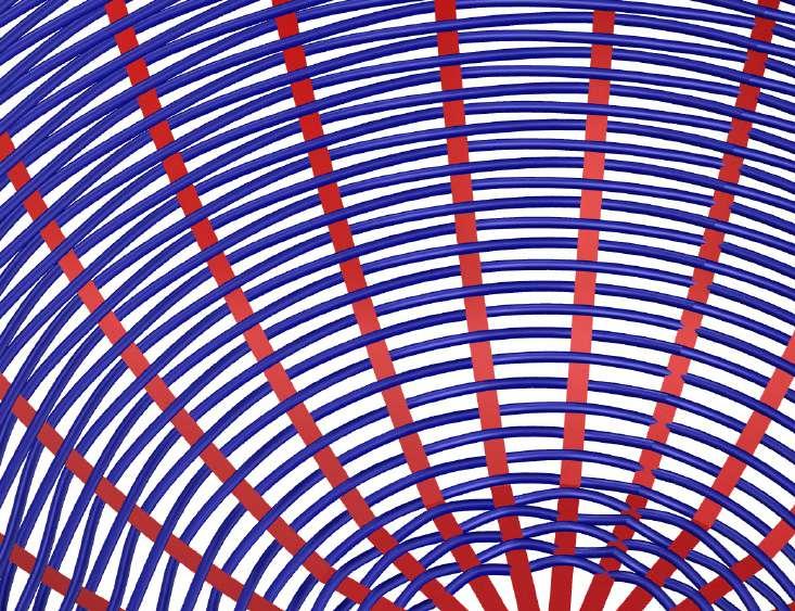
Frame and Weave Basket
Hierarchal (primary and secondary members) basket weaving is an interesting precedent for scaling up to architectural scale. A shift between moments of structural support and areas of infill/redundancy would be both practical and could be an opportunity for expression.

8
by ABK, Buro Happold, Frei Otto in Dorset, England
2.
1.
1. Primary structure (frame)
2. Secondary weaving holds frame in place (moving element)
Potential for creating strong, stiff areas of surface which can vary in density. Possibility to insert further members to strengthen locally.


9
Hooke Park Training Centre
by ABK, Buro Happold, Frei Otto in Dorset, England
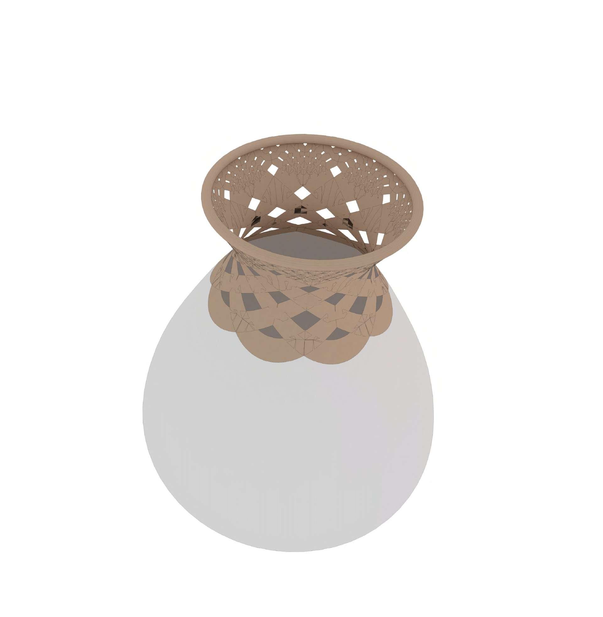
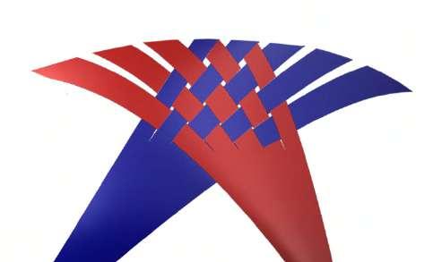
Tri-axial weave (kagome) basket
1.
1. Tri-axial weave made of 3 members
10
Member splitting technique (rokansai basketry) Splitting of members can enable a transition between structural elements and between woven surfaces.
Highly
Artefact 01: Column studies
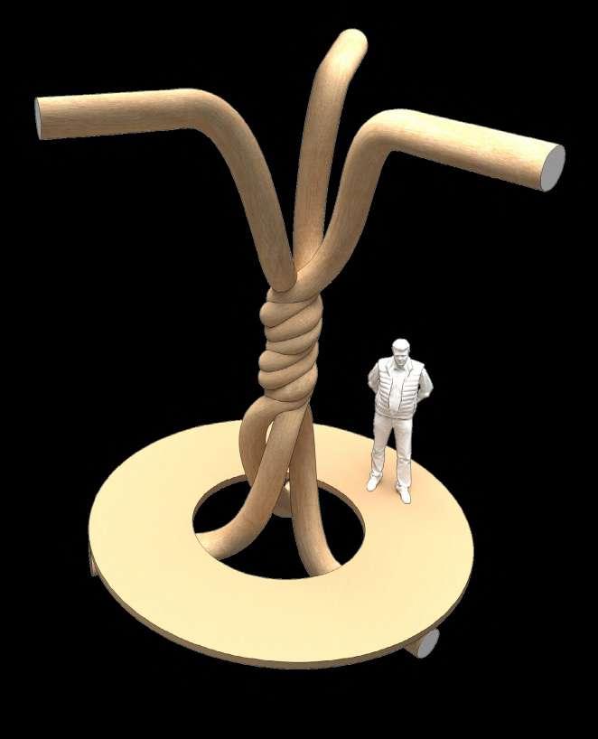
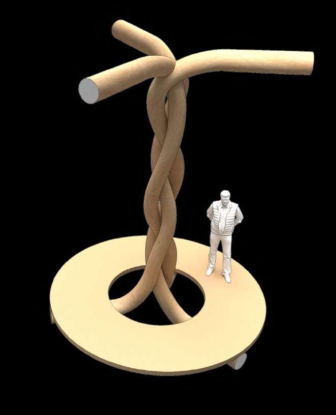
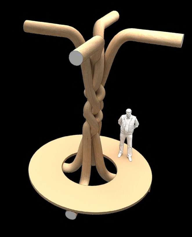
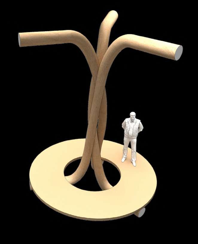
Investigating the
for a
11
potential
tectonic strategy using the deformable timber member at the building scale. Initial study looks at the column as a series of woven members.
Basic weave: most likely fixed intersections
Braid posible with 4 members +
tensioned weave creates intersection of greater tortion/deformity
Condensed weave is more dynamic
Spatial Testing
Artefact 01: Column studies - most effective
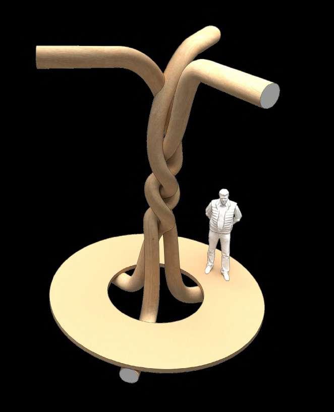
Two studies judged most effective are based on a three-member intersection with a braided weave (diagonal crossing pattern), and a hierarchal weave pattern where a smaller flexible moving element binds together the 3 standards.
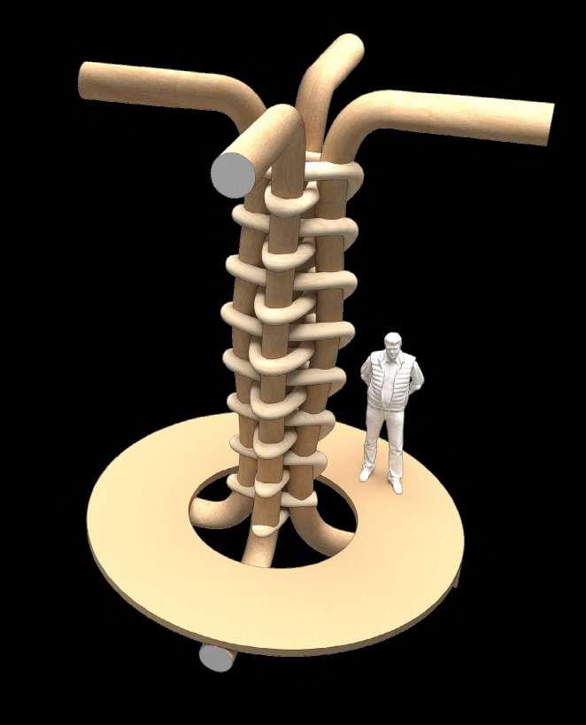
12
Frame + moving element column
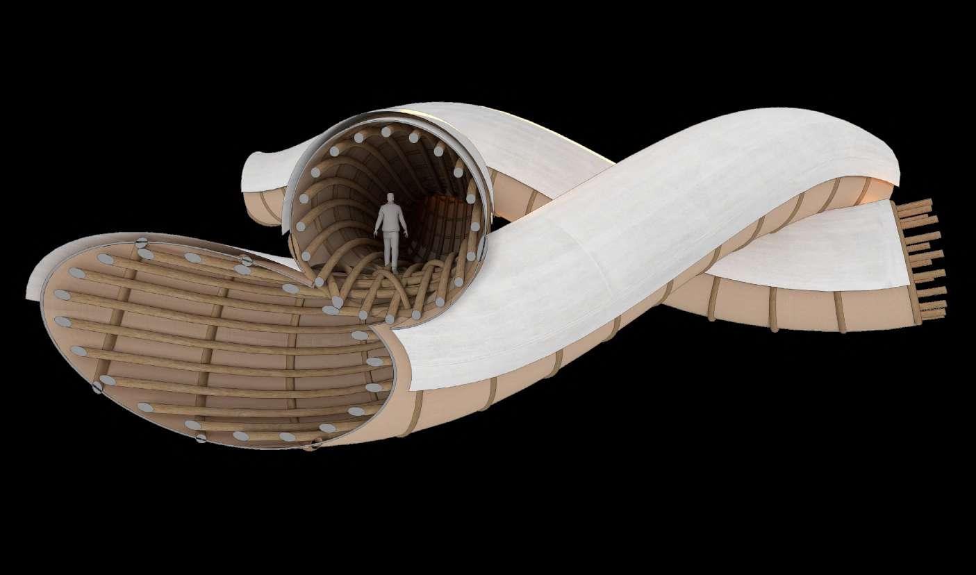
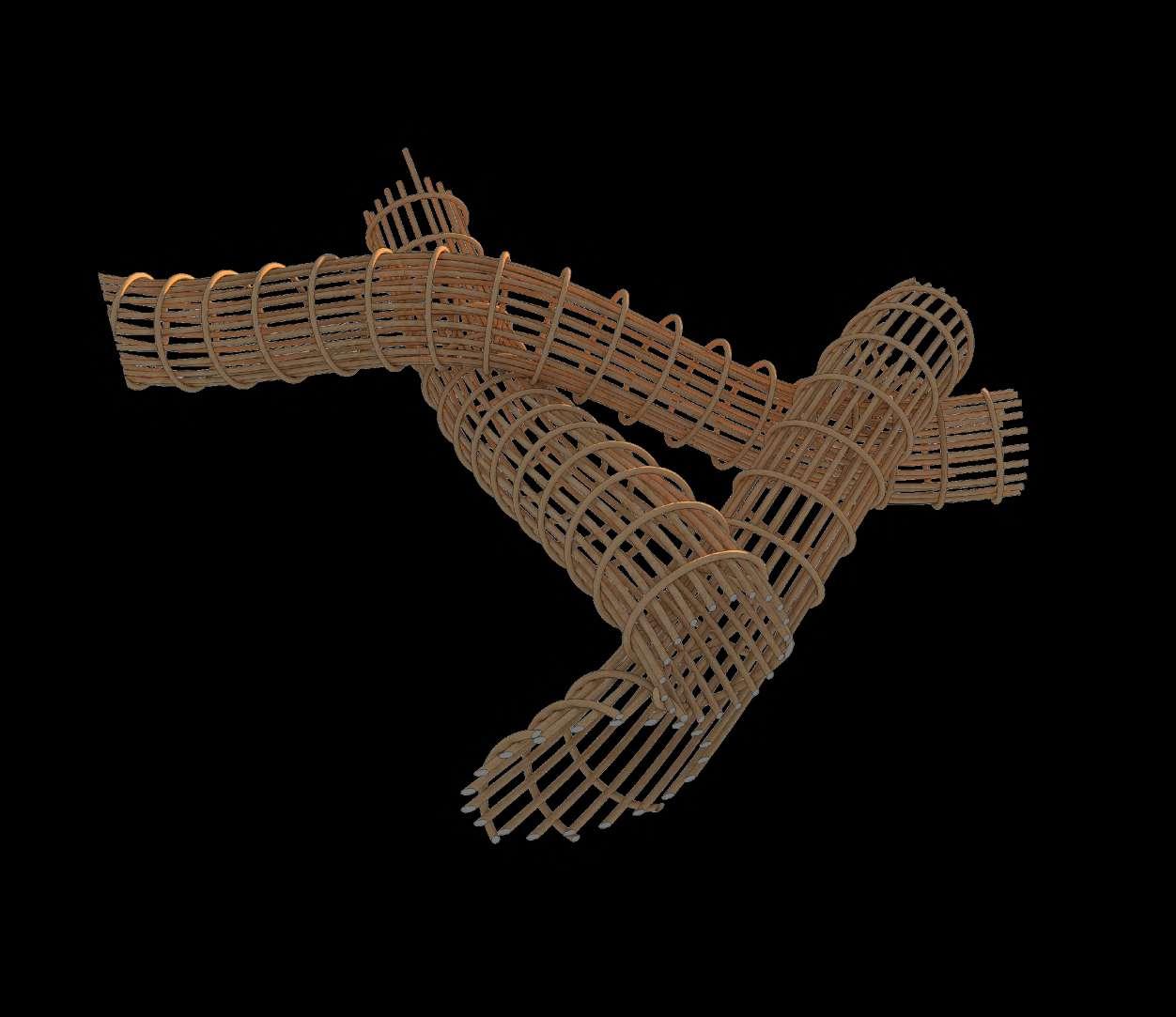
13
The tri-axial weave could be applied at a building scale to create a series of interlocking/interweaving spaces. Deformable members form a skeleton which gains supports from those interlocking with it.
Hooke Park Training Centre
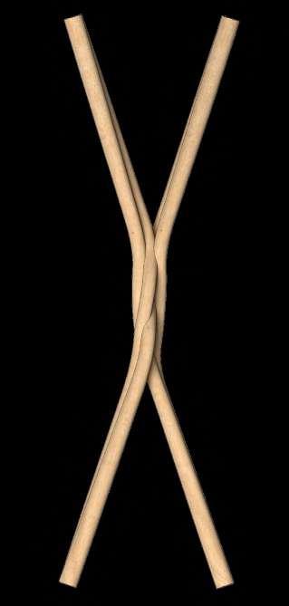
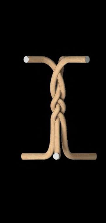
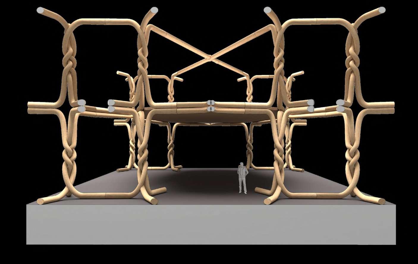
Artefact 02: Braided System
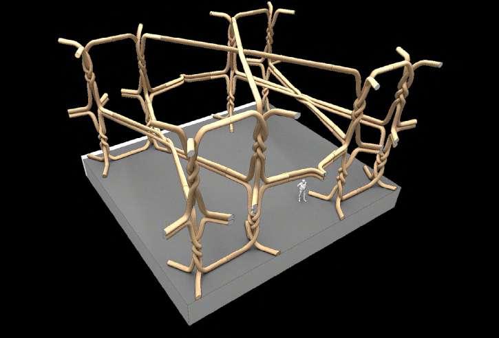
Series of braided members have the potential to form a system, with members scarf or finger jointed to become continuous
14
by ABK, Buro Happold, Frei Otto in Dorset, England
1. 4-way braid forms floor member
2. 3-way braid as column
2.
1.
Park Training Centre
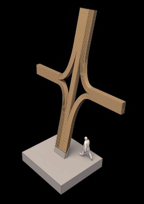
Basic Variations of Column/Beam Laminations crosslamintion, branching, peeling, investigated as lamination approaches for member transition from column to beam. Opportunity to create continuous structure where lamination types can be optimally applied using this language.
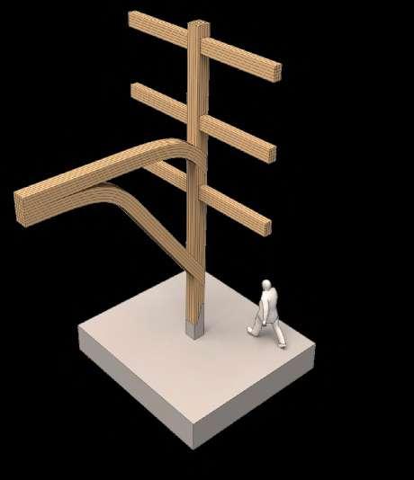
Single-curved Low curvature
Double-curved Low curvature
Single-curved High curvature
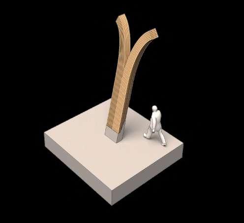
Double-curved High curvature
r / 200 = lamella depth
15
Hooke
by ABK, Buro Happold, Frei Otto in Dorset, England
1.1 Branching 2.0 Curved Lamination
1.2 Crosslamination
1.3 Peeling
Curved Glulam Fabrication Procedure
Lamellae machined from raw timber
Twisted Lamination: Adding tortion to a glulam blank adds some fabrication complexity but could also be employed on single curved elements to add complexity with reduced steps
Existing optimisation approach for generic beam
compression
neutral axis
High grade timber in areas of higher stress/ strain
Hooke Park Training Centre by ABK, Buro Happold, Frei Otto in Dorset, England
Glulam Systemics 01: Fabrication Procedure
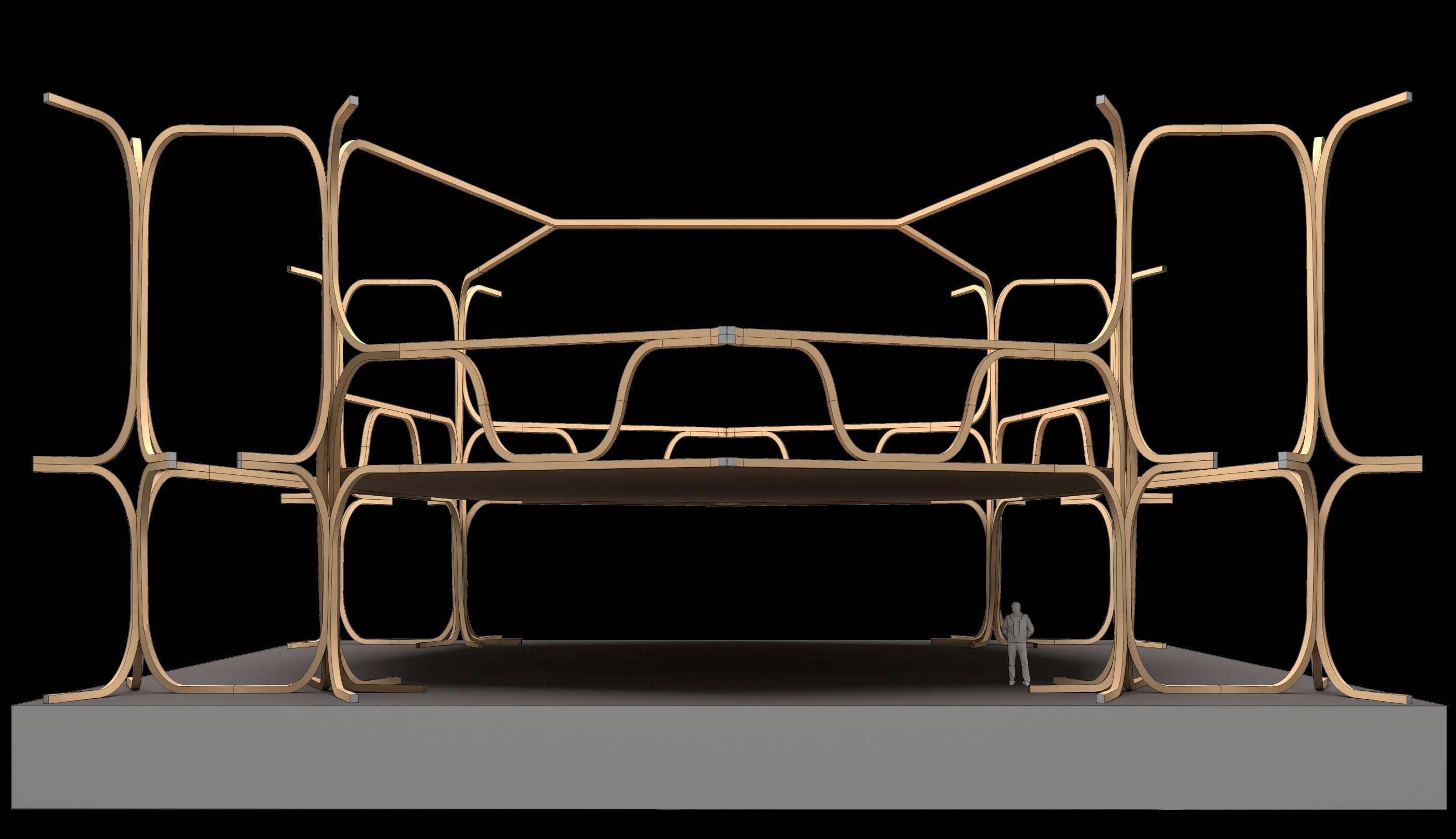
The project speculates on the application of singly and doubly-curved laminated timber elements, forming the nodal conditions within a volumetric frame structure. It looks to intersect and develop the existing procedures for curved glulam fabrication outlined above.
16
Existing Glulam Typologies
INVCREASED FABRICATION COMPLEXITY
tension Straight
Glulam Blank
Single Curvature Double Curvature
Finished component machined within blank
Lower grade timber (juvenile timber or greater knot density) in areas of lower stress/strain toward neutral axis
2 or 3 axis gluing on reconfigurable press Robotic mill shaping
Lamellae machined from raw timber
Typical Blank Types
A1. Straight blank for straight component
Glulam Blank Finished component machined within blank
A2. Finger jointed blanks for single curvature component
A3. Finger jointed blanks for double curvature component
Non-curved / Jointed Blanks
Single Curvature Blanks
B1. Single curvature blank for single curvature component
B2. Single curvature blank with integrated tortion
B3. Single curvature blank for double curvature component
Double Curvature Blanks
C1. Double curvature blank for double curvature component
C2. Double curvature blank with integrated twist
Hooke Park Training Centre
Glulam Systemics: Glulam Blank Types
Lower Grain allignment/continuity but faster fabrication time
Good grain allignment but limited formal complexity to single curvature
Good grain allignment but very limited formal complexity
Good grain allignment/continuity but complex fabrication procedure
Forming blanks can be a multi-stage procedure: when forming blanks with integrated tortion, for example (Svilans, 2020). Most industry standard methods sacrifice grain continuity and create a greater amount of waste. My project proposes a targeted application of high curvature limited to connection points, with the majority of the building being composed of straight, easily fabricated parts. Grain continuity is prioritised due to its structural benefits.
17
by ABK, Buro Happold, Frei Otto in Dorset, England
Broadleaf tree stress adaptation: Junctions are concentrations of stress which the tree must adapt toward to resist (Mattheck)

Compression adaptation Tension adaptation
1. Orientation and intelocking of wood fibres at
Typical hardwood anatomy: Material Anisotropy down to cellular level

A. Wood fibres run axially (95%)
B. Wood rays
Form optimised for mechanical stress. Even a slight deviation results in much higher stresses (Mattheck)
tensile force

bending
2. Material optimised to resist tensile forces in broadleaf, compressive in conifer (reaction wood) at branch
Lath in gridshell : Use of deformable member to create single thin skin. Dynamically activated on site
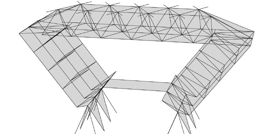
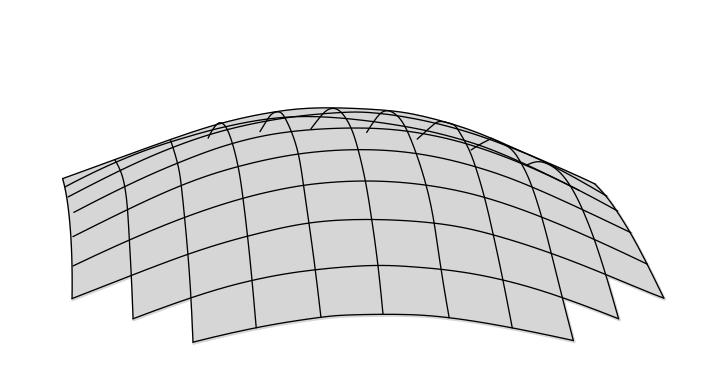
Contemporary Glulam Manufacture: static aggregations of lamellas held in bending with glue assembled as ‘puzzle pieces’
Hooke Park Training Centre
by ABK, Buro Happold, Frei Otto in Dorset, England
Notion of volumetric frame could be a way to break free of master surface adherence status quo in glulam construction
Spatial Strategy
Timber: Extreme Anisotropy, Continuous Grain Connections
Completed in 1989, the workshop building at Hooke Park demonstrates a novel application for green roundwood thinnings, a waste product of forest management, from the surrounding woodland. Typically of small diameter (50-100mm), the thinnings were cold bent into a series of rigid structural shells, creating a large span, yet lightwieght, striking space. Novel jointing and assembly methods were developed for using this underused material.
The anisotropic nature of timber can be harnessed by designing connections around a continuity of members within a lamination, as with tree branches. This can create highly stiff connections with minimal subtractive machining for the purpose of jointing.
18
‘fork’
?
1.
2.
B.
A.
1. Primary Structure
2. Secondary Structure
3. Tertiary Structure
Hooke Park Training Centre
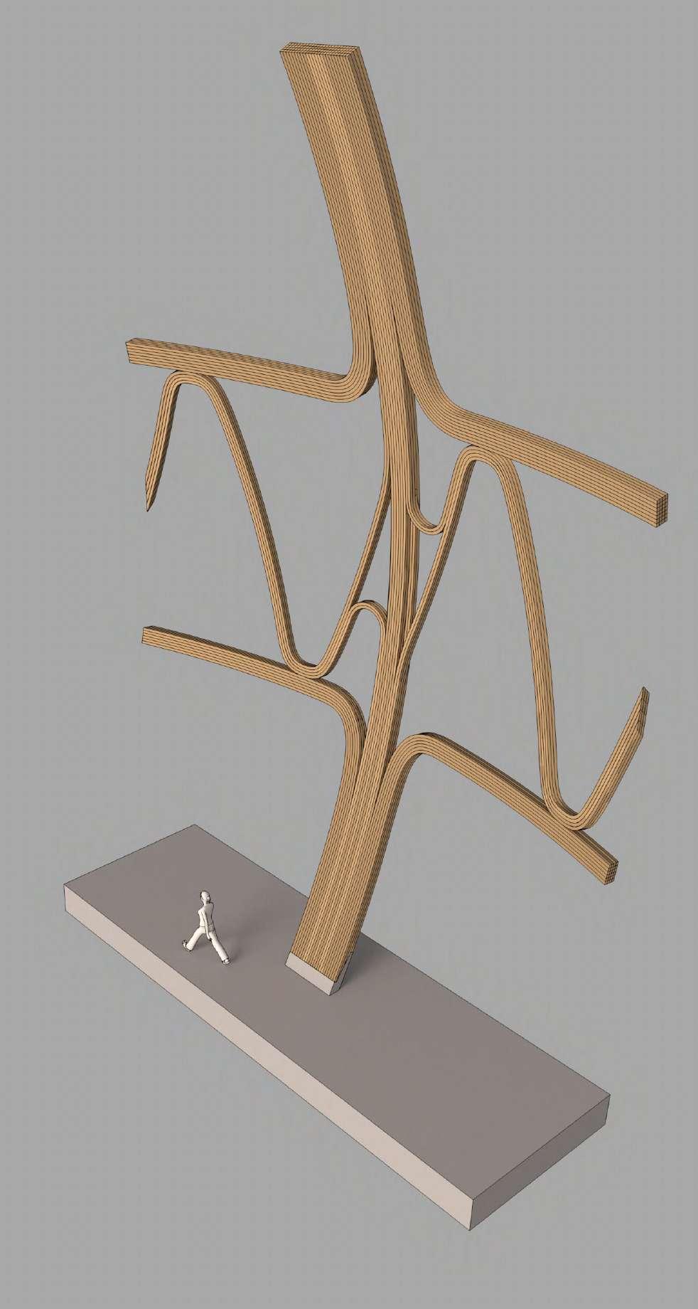
Establishing heirarchy within a component Multiple laminated elements can come together to form prefabricated building components with integrated hierarchy.
19
by ABK, Buro Happold, Frei Otto in Dorset, England
1.
3.


20
Hooke Park Training Centre
by ABK, Buro Happold, Frei Otto in Dorset, England
Lamella to Lath: Transiation from member to tensile surface Possibility to create conncection to hanging roof surface using peeling lamination logic.
1. Laminated tensile connection
2. Single member surface
1. 2.
by ABK, Buro Happold, Frei Otto in Dorset, England
Divergent Lamination
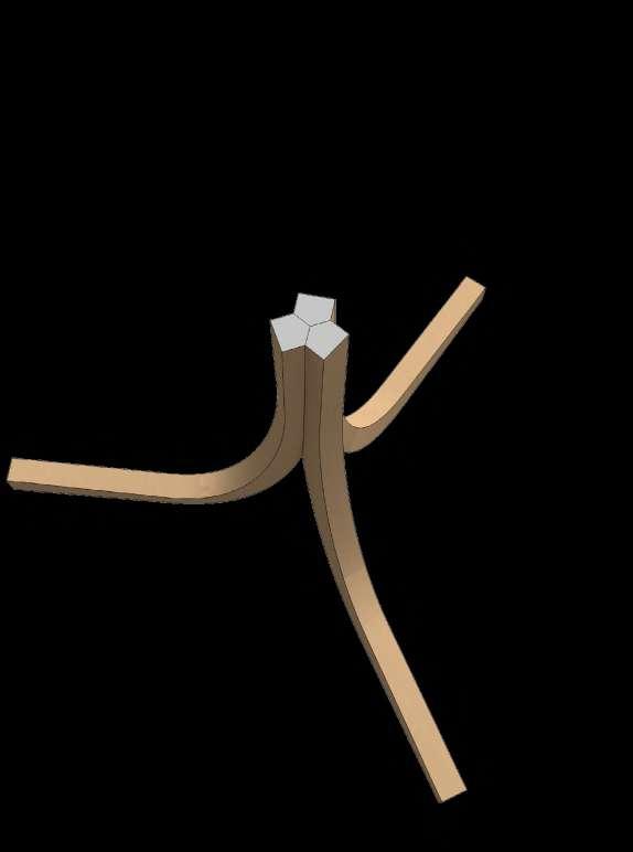
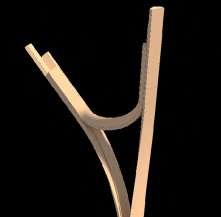
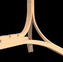
Weaving strategies can be interpreted more practically in timber construction as laminated connections. The language of interweaving and knotting, splitting and diverging can be applied well. Initial fragment re-interpreted as tri-member lamination. Members twist and split from oneanother to enable assembly.


21
Members can diverge to form different structural types Moments of divergence can also be varied to increase structural height, for example A more volumetric approach.
22 23
Hooke Park Training Centre by ABK, Buro Happold, Frei Otto in Dorset, England
1. Less complex curvature allows for larger scale lamination H=40mm
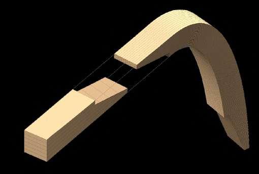
2. Higher degrees of curvature fulfilled by smaller lamellas H=3mm for 600mm radius
by ABK, Buro Happold, Frei Otto in Dorset, England
Additional elements add strength and complexity Members twist and diverge from each other to meet others, providing structural height or moments of support. Lamination can be achieved through discretisation throughout the assembly. This could allow for targeted placement of high grade vs low grade timbers in response to stress distribution and curvature.
24
1.
1.
2.
2.
Spatial Arrangements
Fragment 01: Modulating the ground
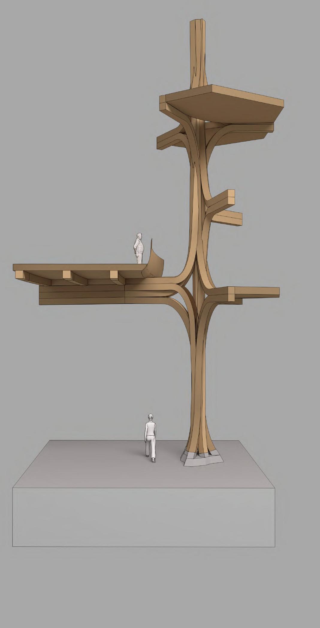
A variety of different node conditions for continuous member laminations can be produced by modulating the ground. Members bundle for column supports and stack where they need to span. Services ‘weave’ between the hollow nodes, a weaving of two systems.

25
Fragment 01: Continuity/Componentry
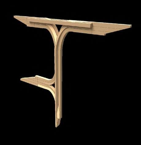
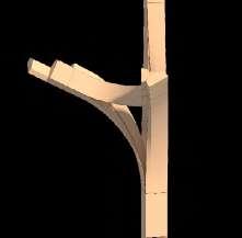
In contrast to the component based logic of members and connectors of previous frame systems, these arrangements make use of the anisotropic nature of timber by having connections built into the components. Just as the grain is continuous within the tree branch Lamellas are continous through the connections.
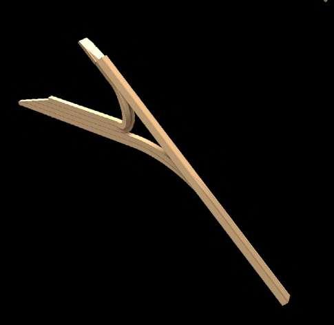
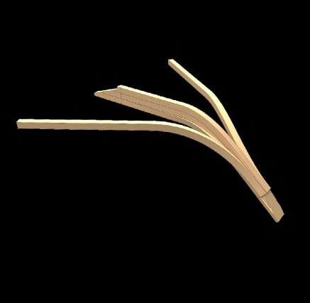

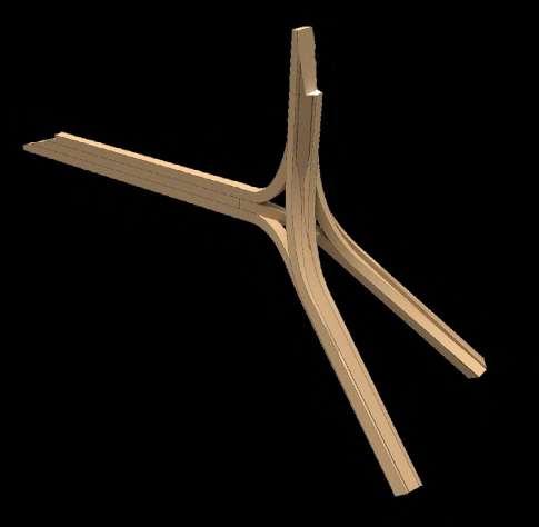

26 27
Hooke Park Training Centre by ABK, Buro Happold, Frei Otto in Dorset, England
1.
2.
5.
3.
1. 4 way node condition 2. Column to beam condition 3. Support to
with branching 4. Side support to floor beam (longer span) 5. 3 way node condition
4.
roof beam
Hooke Park Training Centre
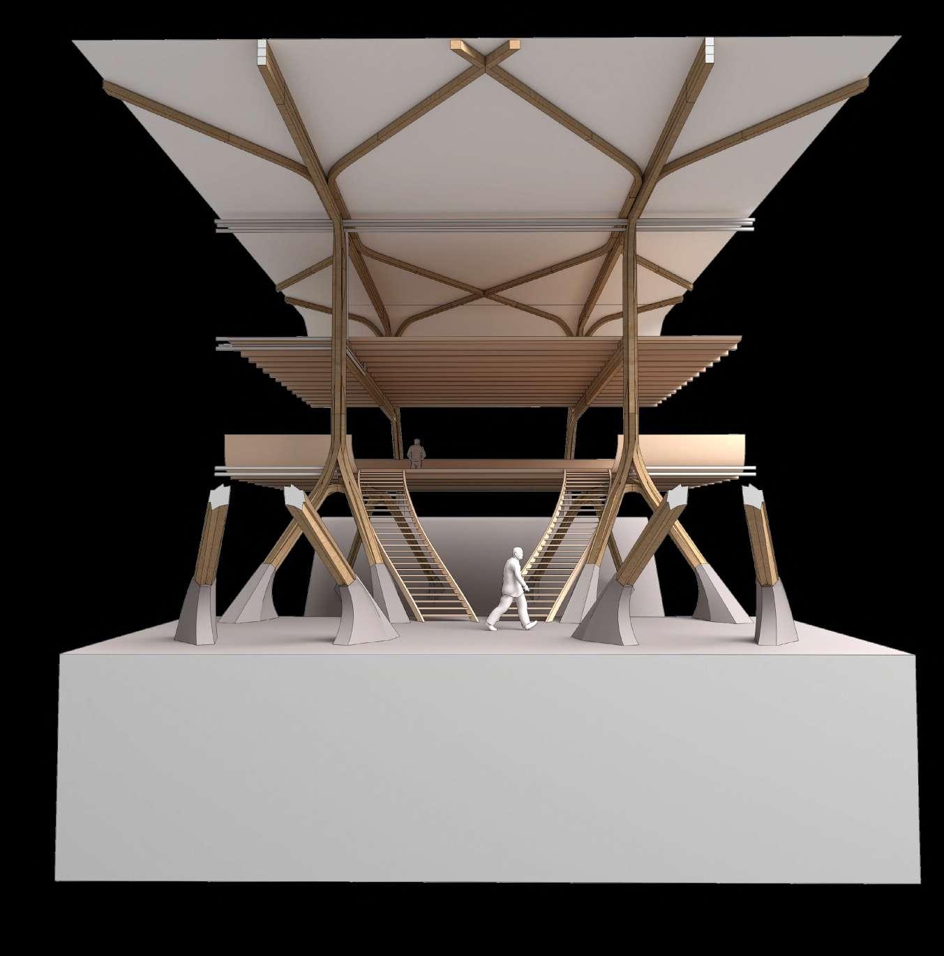
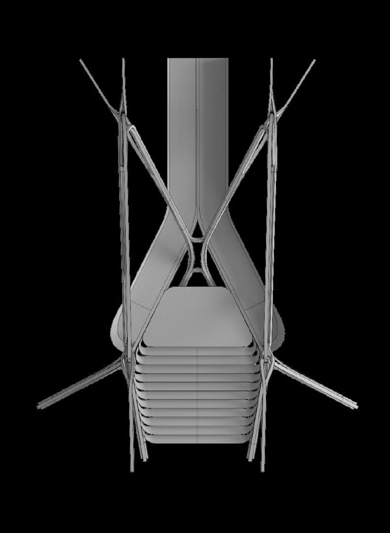
Fragment 02: Increased heirarchy within aggregations Different bundling strategies result in more differentiated structure. Integration of ancilliary elemtents (stairs, furniture) into member aggreagation allows continuity of design language.

28
2
1.
1. Series of cross-bracing elements act as tensile members
2. Floor geometry results from nodal twist
by ABK, Buro Happold, Frei Otto in Dorset, England
Hooke Park
Fragment 02: Differentiated components

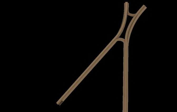
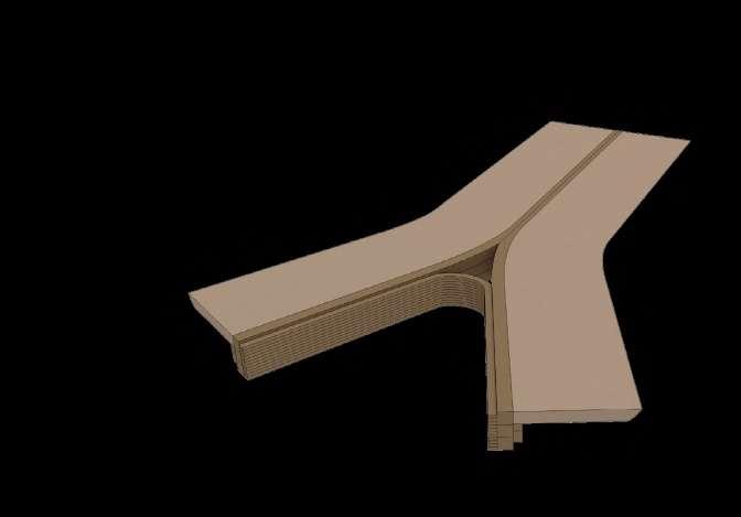

Greater differentiation is achieved through different aggregation strategies for building’s components. Aggregations could be optimised to perform strucurally.

29
B.
E.
A.
F.
D.
A.
G.
E.
D.
F.
G.
5. Possibility to integrate stair and other elements in same language
3. Column to beam transition can involve multiple members
4. Series of cross-bracing elements act as tensile members
A B C D E
F G
1. Components gain complexity through integrated twists
2. Members can converge and split globally and within aggregation
Training Centre by ABK, Buro Happold, Frei Otto in Dorset, England
Fabrication tests

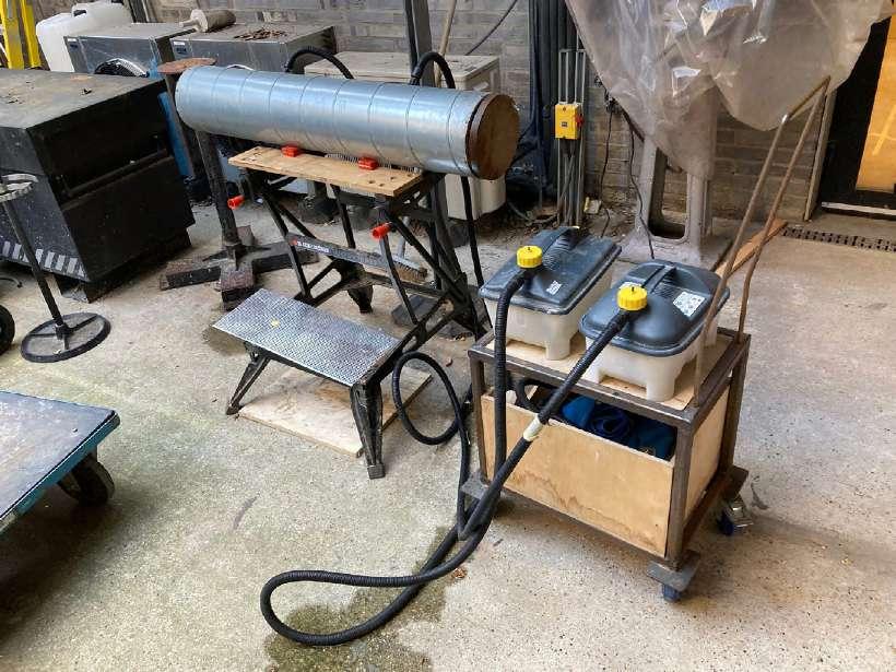
Complex intersections and curvatures tested at model scale
4 way column/beam connection
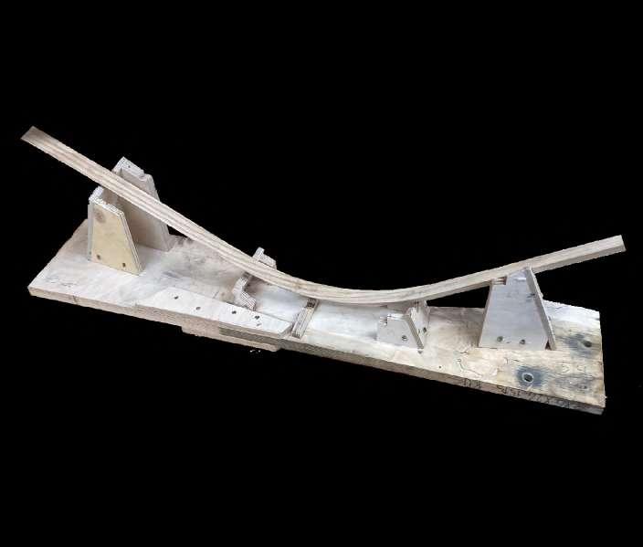
Branching nodal element tested at 1:5 scale. Steam bending was employed as an appropriate technique for achieving curvatures at the model scale. Timber machined and jig fabrication for one member.
30
Timber steamed to achieve curvature
Bending jig fabricated
1. Bundled member 4-part
2. Bundled member 5-part
3. Stacked member 3-part
1. 45 degree mitre joint
2. 54 degree mitre joint
001. Single member cut and bent to test workflow
1.
3.
2.
2.
1.

31
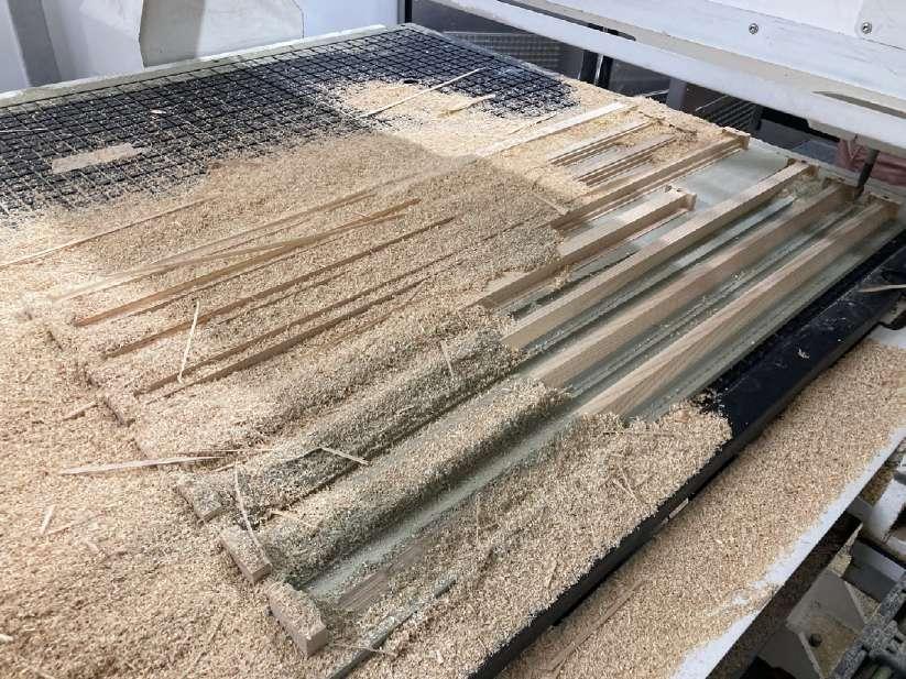
CNC milling of parts prior to bending procedure for changing intersections
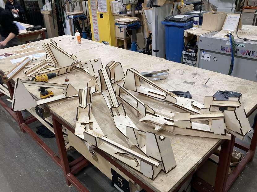
CNC toolpath to mill complex intersections of parts 002. Custom bending jigs place material in space and define bend for 8 distinct elements. Designed to be fabricated through planar cutting ie laser cut
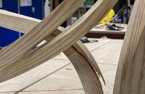
Jig adjstment to include compression strap for tightest bends following failures
Compression strap added to reduce tensile forces during bend
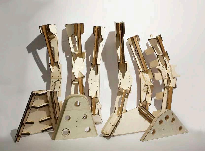
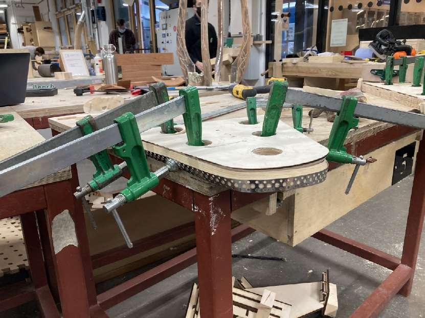
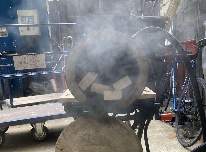
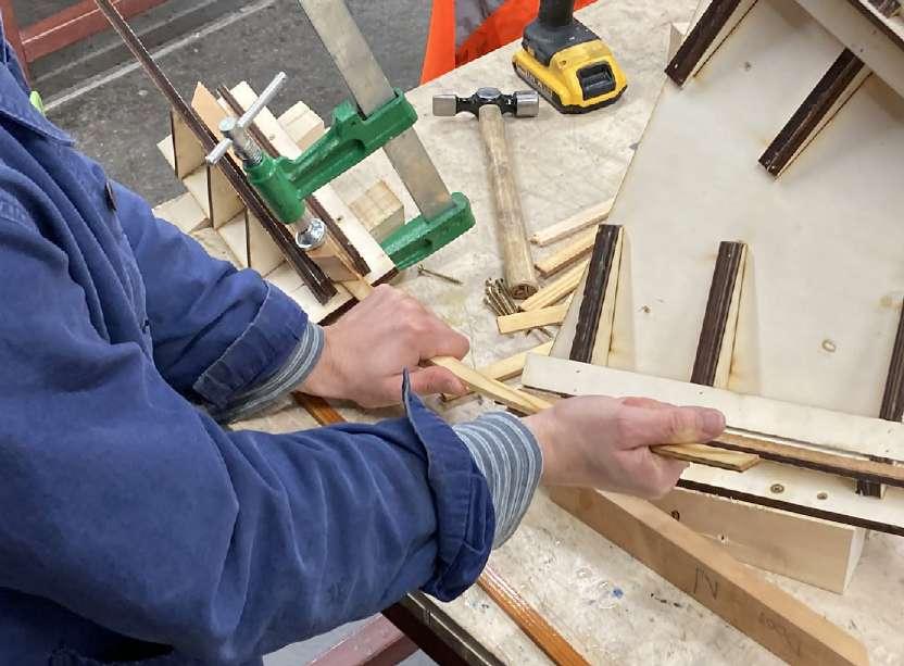
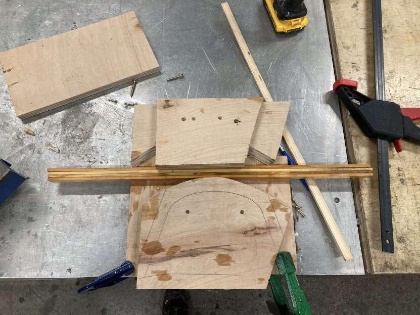
Prototype 01: Milling and Jig Manufacture Complex milling operation creates intersections for steam bent pieces. While most machining in this instances occurs prior to bending, similarly to glulam construction bends need to be placed precisely in space, requiring the fabrication of a series of bending jigs.


32
1. Laser cut bending jig assembly
2. Bending procedure after steaming with jigs
3. Jigs including compression strap for most extreme bends
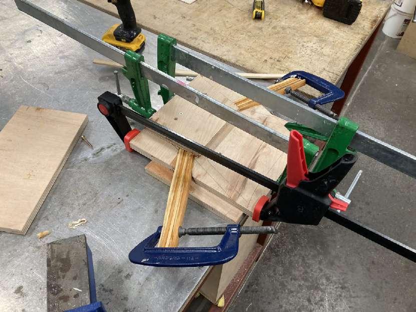
4. Final glue up - use of clamps and tornique collars to pull steambent parts together.
5. 6.
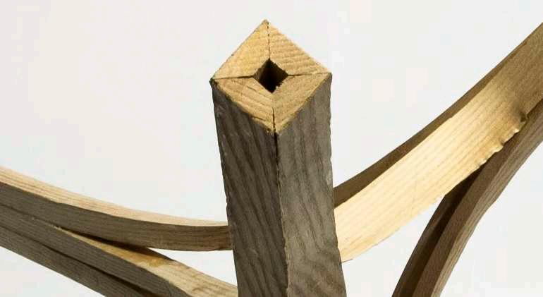
Series of bending jigs fabricated for assembly. (right) 45 degree mitre connection when 4 members bundle (left)
Jig fabrication
Branching nodal element tested at 1:5 scale. Steam bending was employed as an appropriate technique for achieving curvatures at the model scale. Timber machined and jig fabrication for one member.

33
A. 45 degree mitre for 4-part bundle, B. Stacked face-joints, C. 54 degree mitre for 5-part bundle
B.
C.
A.
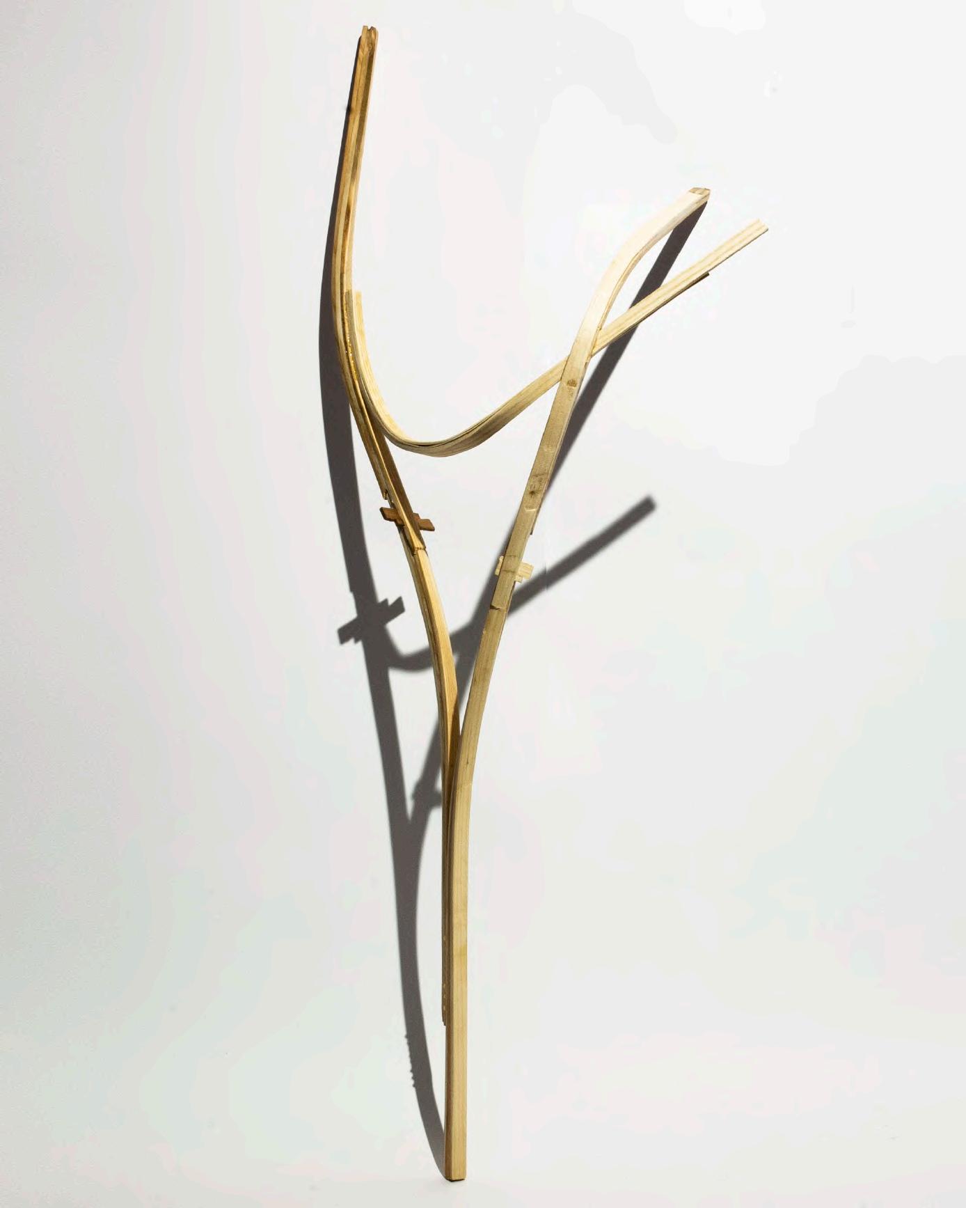
Prototype 01: Milling and Jig Manufacture Complex milling operation creates intersections for steam bent pieces. While most machining in this instances occurs prior to bending, similarly to glulam construction bends need to be placed precisely in space, requiring the fabrication of a series of bending jigs.


34
1. Laser cut bending jig assembly
2. Bending procedure after steaming with jigs
3. Jigs including compression strap for most extreme bends
4. Final glue up - use of clamps and tornique collars to pull steambent parts together.
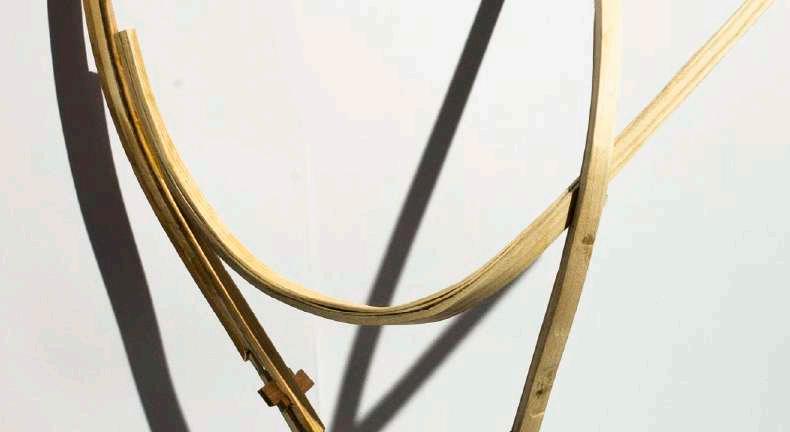
A. 45 degree mitre for 4-part bundle, B. Stacked face-joints, C. 54 degree mitre for 5-part bundle
Jig fabrication
Branching nodal element tested at 1:5 scale. Steam bending was employed as an appropriate technique for achieving curvatures at the model scale. Timber machined and jig fabrication for one member.
35
A. 45 degree mitre for 4-part bundle
B. Stacked face-joints, C. 54 degree mitre for 5-part bundle
B.
C.
A.
Prototype 01: Milling and Jig Manufacture Complex milling operation creates intersections for steam bent pieces. While most machining in this instances occurs prior to bending, similarly to glulam construction bends need to be placed precisely in space, requiring the fabrication of a series of bending jigs.
36 section 2 brief and concept design
Hanseatic League Associated Cities Hanseatic League Chief Cities Other Important Trade Centres Hanseatic area of influence
Brief Research
Reinterpreting the medieval craft guild for a contemporary context
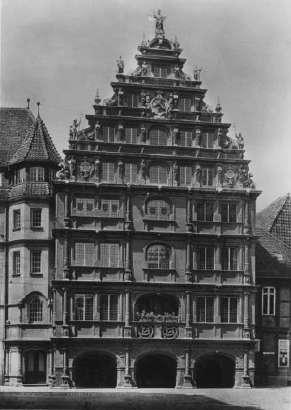
Guildhouse Locations and Significance of guild typology in the Hanseatic cities Guildhouses can be found throughout Germany as a remnant of past forms of production and management. Often these buildings took on a civic role, a function which continues today but divorced from a production context. Particularly the northern cities of Lubeck, Hamburg and Bremen enjoyed prosperity under the guild system as members of the Hanseatic League: a trading body controlling 13th- 15th century commercal activity in northern Europe.

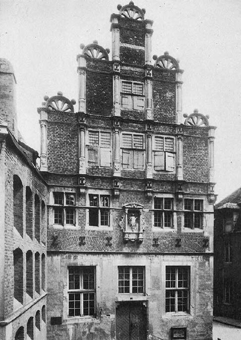
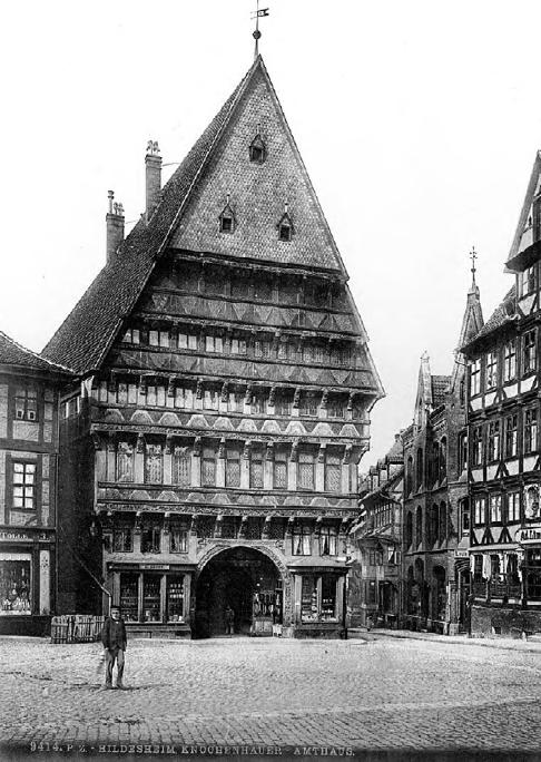
Lübeck in north of the country has strong history of guild controlled production. Formerly known as the ‘key to europe’, the central hanseatic city
37
3. Clothmakers Guildhouse Braunschweig (1591)
4. Carpenter’s Guildhouse Zurich (1430)
2. Butcher’s Guildhouse Hildesheim (1529)
1. Shoemaker’s Guildhouse Münster (1589)
1.
Bremen. Hamburg. Brunswick. Cologne.
Danzig. Stettin.
Riega.
Revin. Visby.
Stockholm.
Lübeck.
2.
4.
3.
The Guildhouseas a civic building
The Guild house (Gildehaus or Zunfthaus) fulfilled a civic function for guild members. Often they were a place of lively activity: for gathering (feasting, festivals) and knowledge exchange, regulating work (apprentice examinations) and commercial activity (a market and fair space). Especially in industrial towns these concentration of skilled work, embodied by the Guildhouse, becomes a principle part of urban society and culture.
38
Guildhouse Functions
Master
Regulation of labour
Collective devolution carried out
Journeyman
Protection of self-interest
Lobbying of rulers for priveleges
Regulation of products
Inspection of product quality
Regulation of market and materials
Innovation exchange/regulation
hereditary admission common
Requirement for skill exchange
Guild Assembly and Festivities
Tradition of travelling once appreticeship ends still remains today
Apprentice
Decentralised Production
Commercial trading at markets/fairs
11th Century: Decentralised production first organises into guilds in cities
12th-15th Century: Merchant and craftguilds enjoy prosperity in period of evolving global trade.
16th-17th Century: Emergence of regulated companiesand other associations of wealthy merchant capitalists leaves guilds
Hooke Park Training Centre
19th-20th Century: abolition of craft associations in Europe in favour of industrial methods with centralised organsiation of manufacture.
by ABK, Buro Happold, Frei Otto in Dorset, England
21st century: rise in more affordable methods of digital manufacture allows for a return of artisanism
Spatial Strategy
Completed in 1989, the workshop building at Hooke Park demonstrates a novel application for green roundwood thinnings, a waste product of forest management, from the surrounding woodland. Typically of small diameter (50-100mm), the thinnings were cold bent into a series of rigid structural shells, creating a large span, yet lightwieght, striking space. Novel jointing and assembly methods were developed for using this underused material.
The Guild as protector of the crafts and an organizational body The guild reflected a predilection for ordering society. Each guild set the terms of its craft: the forms of labor, standard of product, and methods of sale. The educational structure of the guld sought to regulate and organise labour, a tradition which continues today. The guildhouse was the centrepoint for logistics and commercial transaction. Innovation was encourged through exchange and conversation.
39
En
?
Guild Structure
Monarch Clergy
?
buttons
Buttons symbolise the working week: 6 on the front for 6 days work, 8 internally for 8 hours a day
Headwear
Different hats denote ranks of craftspeople.
60 km radius around home
Apprentice aged 14-16
Journeyman’s piece after 3 years
3 years of travel honing craft
Journeyman
Traveller’s bundle

On one’s journey only specific items can be taken: tools, a change of clothes. Work is undertaken for bed and board.
earring traditionally paid for burial
hats denote years travelled
Traditional vs. Digital Production
Walking stick carved
Flared work trousers
The trousers originate from the shipping industry where they could be easily removed if in water.

Masterpiece and Master exam
‘Bundesgeschirr’ or ‘Joining tools’ are carried on the crafsperson’s journey
Travel in specific styles of dress
Master
Carpenter’s sidgel still employed: written is ‘Praise the carpenter’s art’
Carpenter (Zimmerman) continued cultural significance
Many traditions from the era of craft-guild organisation still remain today in the lives of craftspeople in the countries of Germany, Austria and Switzerland, most notably the training system from apprentice to master, styles of dress denoting rank, and the practice of taking a journey. The project taps into these ritualistic and traditional practices: in an age where the landscape of production for these practices is shifting toward digital manufacture.
40
Programmatic diagram
Collective devolution carried out
Lobbying for privileges
robotics and fabrication
Co-ordination of robotic fabrication and A.I. in construction research
Leading of prototyping research and its distribution
Guild Board of Masters
commercial director
Sourcing of raw materials, relationship to forestry, debating trade agreements, commercial guild interests
near future zimmermann?
High-tech meets tradition with the inhabitants of the near future guildhouse who retain some aspects of traditional dress, like headwear education director

Delivery and regulation of apprenticeship training, inspection of masterpieces and examination
chief Lobbyist
Political guild representative, lobbying for representation of crafts, guild priveledges
Hooke Park Training Centre
by ABK, Buro Happold, Frei Otto in Dorset, En
The benefits of contemporary guild organisation
ceremonial director
Leading of ceremonial roles, festivities, guild assembly
A contemporary carpenter’s guild could be structured to engage with these requirements, encouraging a relationship between traditional craft and digital technology, allowing collaborative access to digital tools, knowledge and information and retaining the value of traditional cultural practices. The guild would seek to engage with all levels of the timber building supply chain, encouraging a more sustainable, research-driven construction: a challenge to contemporary norms.
41
Inspection of product quality
Innovation exchange/regulation
Guild Assembly
Commercial trading
Meeting rooms/ offices
Atrium/exhibition space
Prototyping workshop
Lecture Theatre Library
Tavern
Trading rooms
Hooke Park Training Centre
by ABK, Buro Happold, Frei Otto in Dorset, En
Death of the crafts, rise of the post-industrial digital?
Access to digital manufacture at small scale is an emerging industrial artisanism
Potentials of digital manufacture tapped into at small scale level but with benefits of collaboration?
Artisanal
historic resistance to machine production
Nottingham
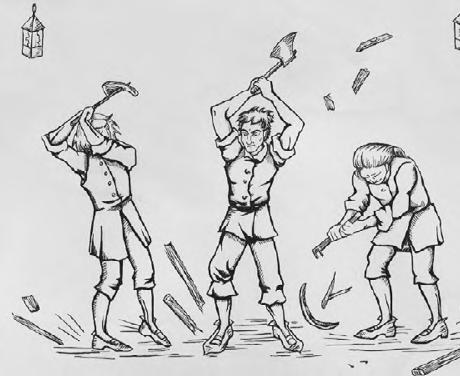
The crafts are in decline throughout Europe as highly industrialised, centralised forms of production continue to dominate. While there is some recent resurgence in interest in these forms of making, many traditional methods of manufacture seem at odds with the technology focussed ambitions of digital manufacture, especially those employed in the most advanced large scale manufacture. However do the possibilities of digital manufacture as tools become more available not suggest a possibility for a return of artisanism and skilled craft?
42
Construction Trades +18% 2005-19 Tendency toward hyper-industrial, centralised production Manufacture digital uptake, EU (2015-20) by company size micro 20% 40% 60% 80% micro small small mid mid large large Construction digital uptake, EU (2015-20) by company size
crafts with resurgence
Artisanal
Artisanal crafts under threat Barrelmaking -46 % 2005-19 Timber Framer +20 % 2005-19 Bookbinding -52 % 2005-19 Boatbuilder +23 % 2005-19 Shoemaker -39 % 2005-19 Joiner +26 % 2005-19
crafts
Luddites 1811-12,
Robotics Robotics Data analysis Augmented
Additive
Internet
The Cloud
milling Bioengineering Butcher -19 % 2005-19 Stone Mason +5 % 2005-19 Barrelmaking -24 % 2005-19 Wood carver +9 % 2005-19 Weaving -100 % 2005-19 Ropemaker +17 % 2005-19
Additive Manufacture
reality
manufacture Simulation Artificial intelligence System integration
of things
CNC
Finishing Trades +14% 2005-19 Commercial Trades +11% 2005-19 Automotive Trades +9% 2005-19 Food Trades -9% 2005-19 Health Work +17% 2005-19 Consumer Trades -10% 2005-19 Artesanal Production Industrial Production ?
Possible Sites in Old City, Lübeck, Hansestadt


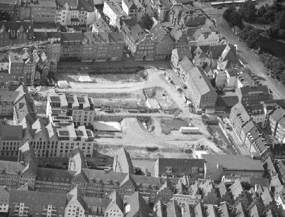
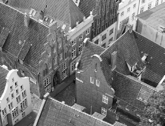

The historic city centre in Lübeck is separated from the rest of the city by the Trave river. Historically this was the cetnre of trade for the Hanseatic league and much of the city’s architecture developed during this era. The gable end dominates and creates a cityscape of highly expressive facades. While the historic architecture which survives offers a strong contextual precedent for any intervention, the city also suffered heavy bomb damage during WWII, leading to hurried developments which are now being torn down.

43
3.
5.
2.
1.
4.
6.
1. Fisch Straße - Post-war construction infilling bombed voids now being replaced
2. Lübeck Market Square - one of two main city squares
3. Petersgrube- Gable-end alongside contemporary infill
4. Hundestraße - one of many streets defined by adjacent gable ends with varied characters
5. 5 Church steeples are key landmarks
6. Koberg Square - one of two main city squares
Old City suffers high level of bomb damage
Offices for Ministry of Industry and Commerce in Hogehus buildings ca. 1890
Schiffersgesellschaft
Chosen site Existing Gable-end removed
Koberg Square City's central square plays host to festivals and events throughout year. Re-pedestrianised in 2010
Unfolded elevation: site one of many gable ends

Site location
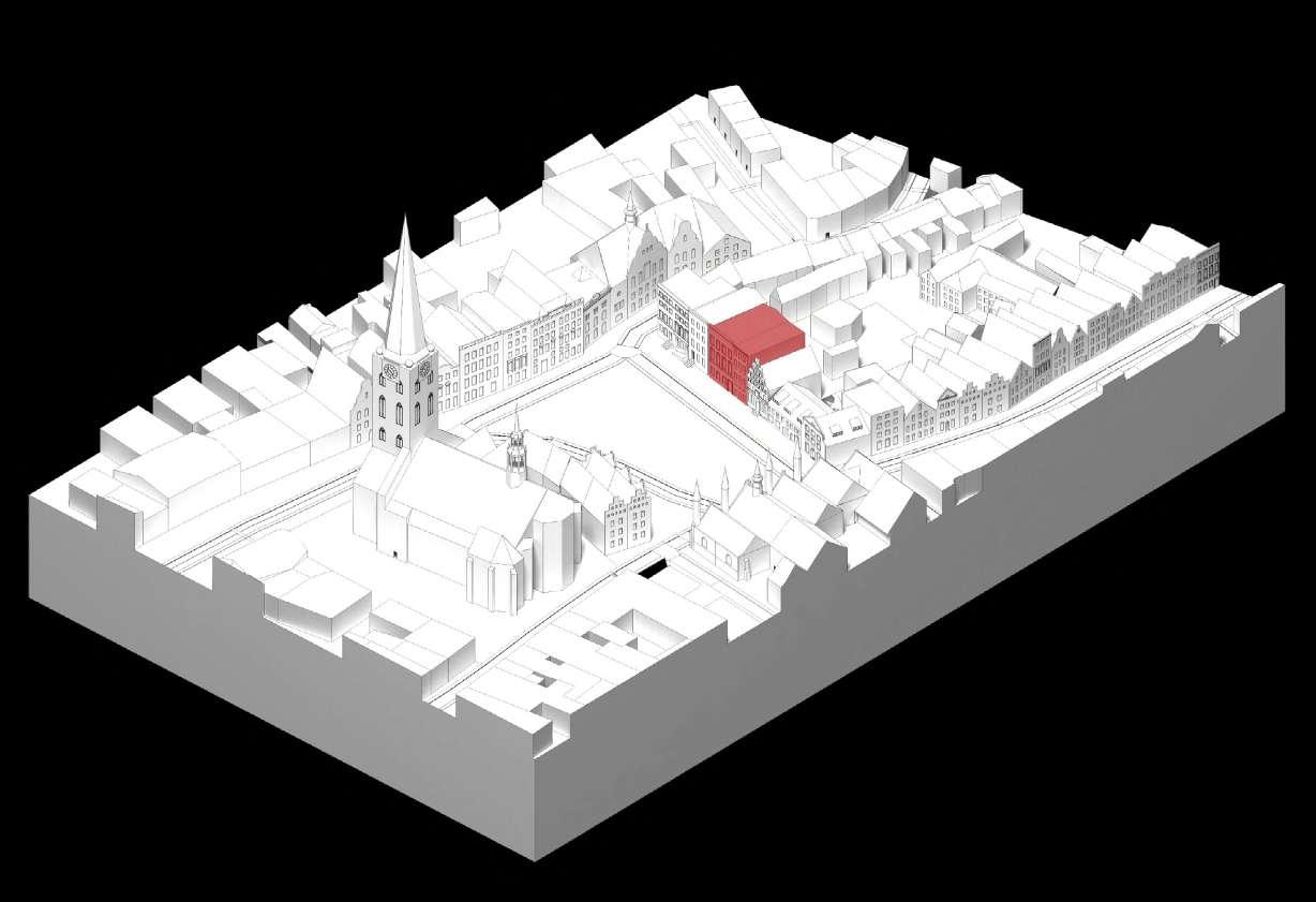
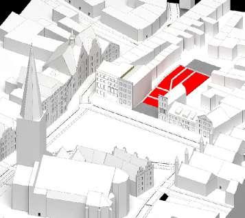
Site Context: St Jakobi Square Main square to the north of the city defined by gable end facades. A fairly constrained site, the project seeks a prototypical study of contemporary fabrication and construction apporaches in relation with a historic context.
Chosen site
44
Heiligen Geist Hospital Restored landmark ca. 1286
Rear yards of city make up predominant green space
Ernestinen Gymnasium School Education for ages 11-18 ca. 1830
Former sailor's guildhouse ca. 1538
Lübeck Chamber of Crafts offices
St Jakobi Cathedral One of the 5 Cathedrals on the old city island ca. 1334
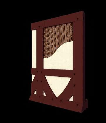
Medieval Timber Frame Construction: a hybrid between frame and infill Timber frames throughout Germany and Central Europe offer precedent for reinterpretation using contemporary fabrication and constructional methods. A way to form surface from members.


as more

45
1.
2.
1.1 Wattle and Daub: most traditional infill of woven timber frame and lime render provides breathable skin for the building
1.2 Brick infill: over time bricks replace infill
practical, semi-industrial solution
2. Traditional framing system: single skin wall relying on pegged mortice and tennon connections
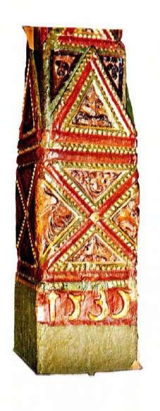
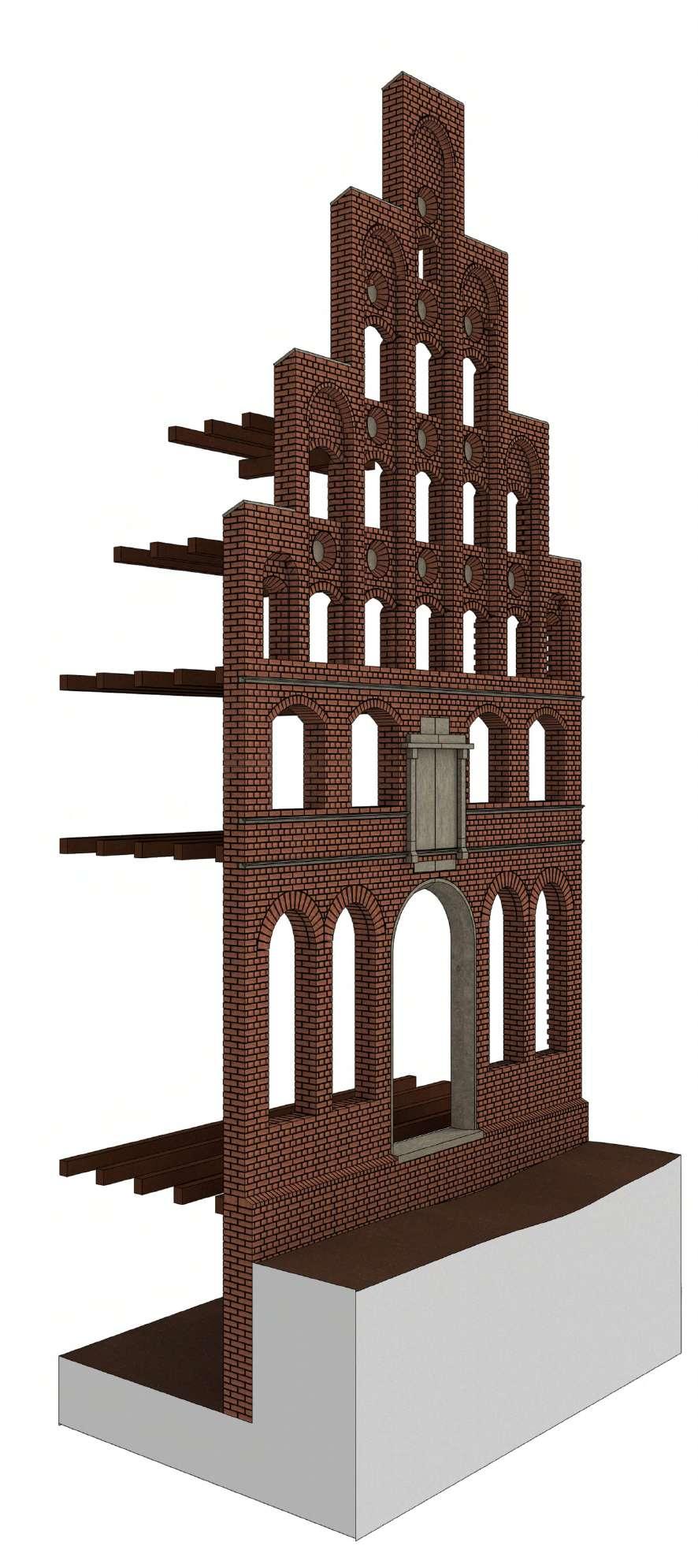
The Gable End type dominates the cityscape in Lübeck. Often these facades would be expressions of place, wealth, ownership and use in their ornamentation. Lübeck has a long history of building in brick due to the availability of clay in the Northern German Plain. Brick would eventually come to dominate the city-scape, although most buildings remained hybrids of brick and timber, the older building material.


46
Lübecker Gable End Type
Hooke Park Training Centre by ABK, Buro Happold, Frei Otto in Dorset, England
Hooke Park Training Centre by ABK, Buro Happold, Frei Otto in Dorset, En

Spatial Strategy
Contemporary Guildhouse Programme Arrangements
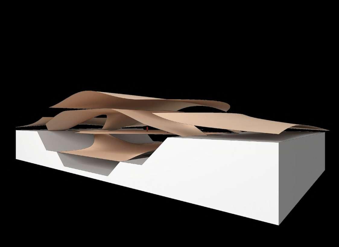
Could a contemporary interpretation of the Gildehaus not again fulfil a civic, commercial and educational function and so provide a space for rediscovering the relevance of craft?
Completed in 1989, the workshop building at Hooke Park demonstrates a novel application for green roundwood thinnings, a waste product of forest management, from the surrounding woodland. Typically of small diameter (50-100mm), the thinnings were cold bent into a series of rigid structural shells, creating a large span, yet lightwieght, striking space. Novel jointing and assembly methods were developed for using this underused material.
47
Lobbying for priveleges
Collective devolution carried out
Inspection of product quality
Innovation exchange/regulation
Meeting rooms/ offices Atrium/exhibition space
Prototyping workshop
Lecture Theatre Library Tavern Trading floor
Guild Assembly and Festivities
Commercial trading at markets/fairs

48
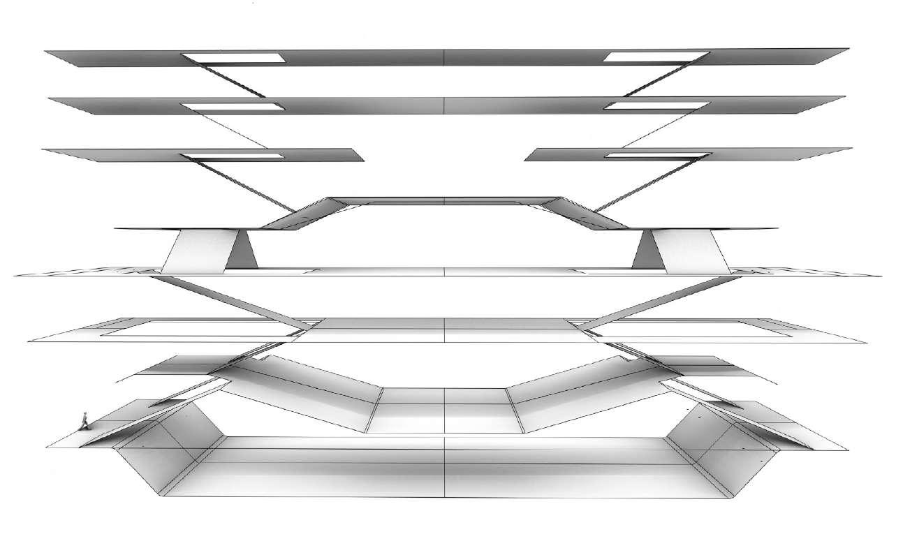
1. The attic: Ceremonial rooms and Library
2. Offices and prototyping
3. Member's quarters (Gesellen Herberge)
4. Member's tavern
5. Public tavern
6. Exhibitions
7. Lecture hall 8. Trading Floor
Hooke Park Training Centre by ABK, Buro Happold, Frei Otto in Dorset, England
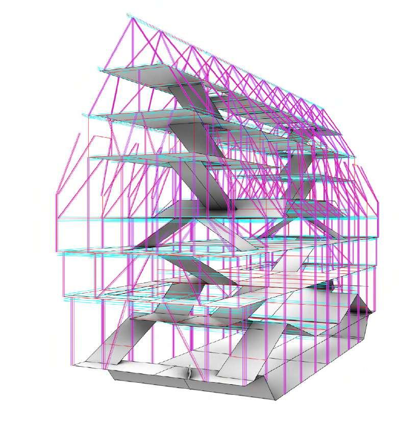
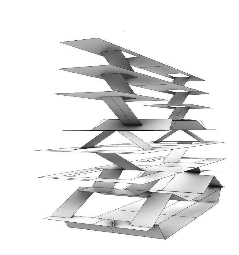
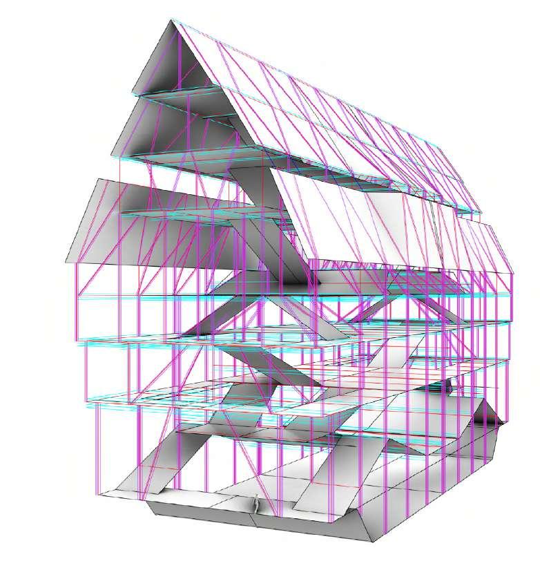
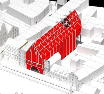
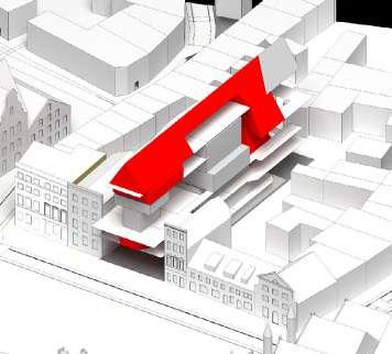
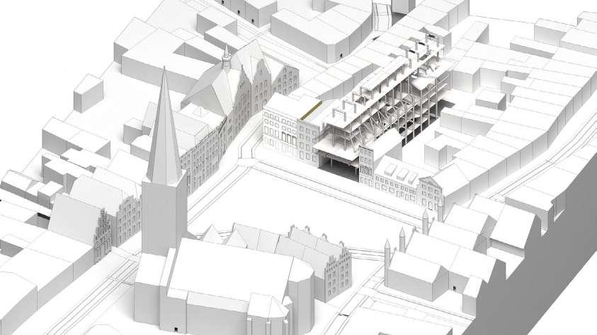
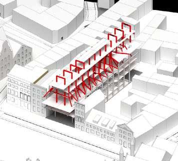
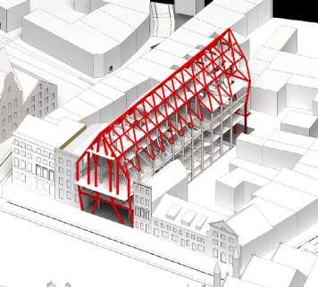
Massing study: Stacked organisation Stepped timber construction using contiuous nodal connection to creates stacked assembly flanked by existing buildings
Massing studies: Structural
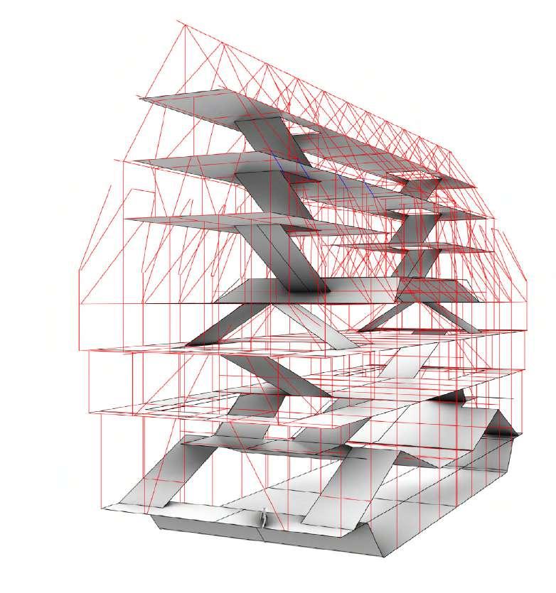
49
Hooke Park Training Centre by ABK, Buro Happold, Frei Otto in Dorset, England
Approach Stepped timber construction using contiuous nodal connection to creates stacked assembly
Building

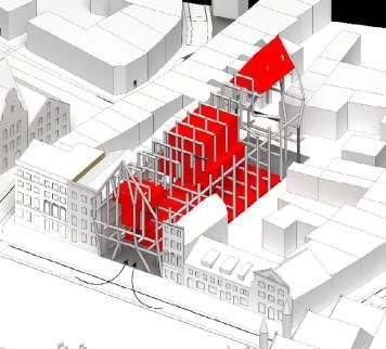
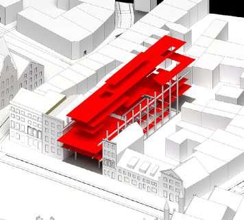
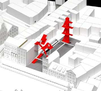


50
Genesis
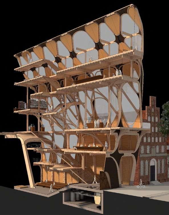
Building genesis describes key moves and ambitions. The guildhouse is designed around a number of private and public functions, seeking to act as a locus point for contemporary crafts and also take on a civic role in the city: providing space for congregation and craft appreciation within an extraordinary timber structure.
01. Lübeck as former metropolis surrounded by current production centres
04. Public hall set back from street
07. Branching transfer structure above party walls allows 3-part organisation on upper levels
10. Private functions interweave with public ones. Wide circulation spaces allow the two to collide
13. Building organised around 2 staircases: a front feature staircase and rear utilitarian one
02. Public square in historic centre has potential to act as a civic centre in the city
05. Post and beam structure around hall creates tri-part plan organisation between party walls
08. Branching facade structure and roof lattice act as expressive layer to building
11. Servicing strategy integrates servicing within timber stucture and floor cavity
14. Facade infill expresses timber structure. Openings and shading respond to daylight and wind analysis
03. Existing gable end removed
06. Stacked organisation to building with constraining floorplates overhanging square
09. Series of public rooms activate square as civic space
12. Public ground floor creates link between square and green space within city block
15. Decentralised production and artisanism is brought together once again in the city
journeyman refuge
A hostel at the top of the building houses journeying craftspeople on their travels
guild offices
Offices for guild organisation, craftsperson registration
tavern
The tavern at the front of the building enables more informal assembly and exchange between Guild members and the public
Guild meeting rooms
Meeting rooms for signing and discussing trade deals, logistics and policy making
Front feature stair
An double stair builds off the structure of the main hall to draw visitors into the building

Prototyping workshop
While the Guild is mainly a logistical body, a prototyping workshop is found in the building for testing more experimental construction
Library
Enables guild assembly for policy discussion, lectures and presentations
Exhibition room
An exhibition room to showcase the Guild’s research into timber construction and related topics
ceremonial chamber and species archive
Enables guild assembly for private matters. Categorisation of timber species
rear utility stair
Simpler stair and lift to rear of building
Main Chamber
Enables guild assembly for policy debate, lectures, presentations and festive gatherings.
Massing and Organisational Strategy
The building is organised in as a vertical stack between the existing party walls. Public and private functons interweave with ample circulation spaces allowing spill-out and exchange
51
52 section 3 design development
Roof Lattice
Roofing system acts to diagonally brace structure below and as expressive layer to system
post and beam (blue)
upper post and beam
An upper post and beam structure builds up from lower transfers to hold floorplates and support roof lattice
Upper transfer structure
The structure branches in above the party walls, supporting post and beams for constraining plan and retaining 3 part organisation
lower post and beam
Post and Beam system infills around and builds up from lower transfer to suppoer floors
Shear walling
Laminated timber panels brace the structure at the lower levels

facade structure
Facades cantelever out to front and rear of building
main chamber transfer structure
The main hall is formed through a large spanning structure which takes the loads from above
Concrete slab
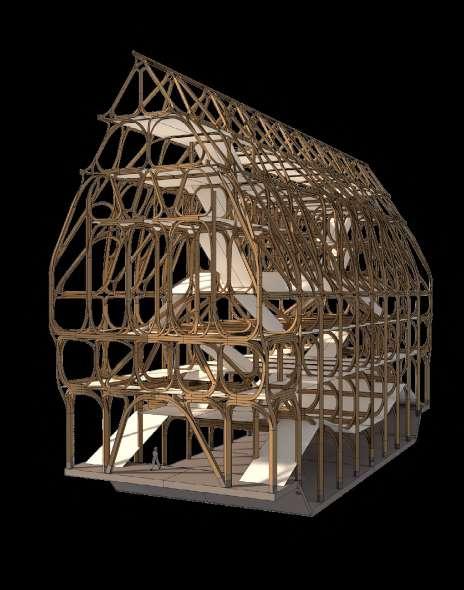
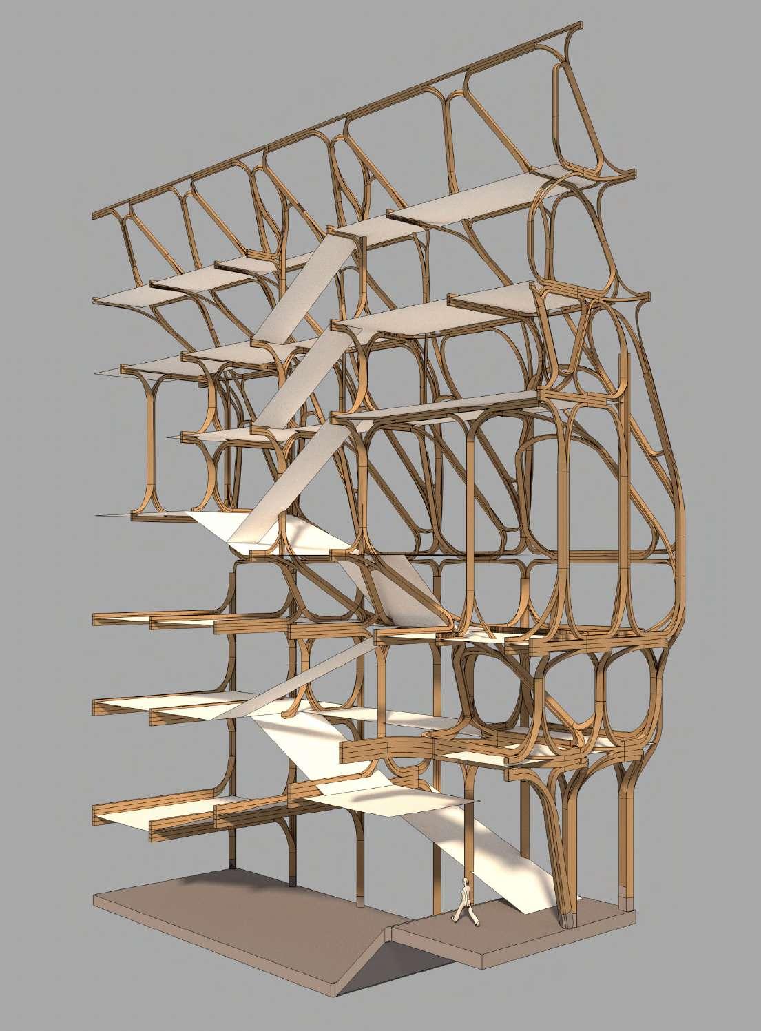
Overall Structural Strategy
Transfer structures carry post and beams which span between party walls. Roof lattice structure and transfer diagonals add stability to the system.

53
Footings designed to transfer loads from structure above transfer structure (red)
Continuous
Structural
54
model: Iteration 01
lamella logic creates a series of different nodal conditions throughout the building. Structural heirarchy is introduced as the members thin as one progresses upwards.
Structural model: Iteration 02
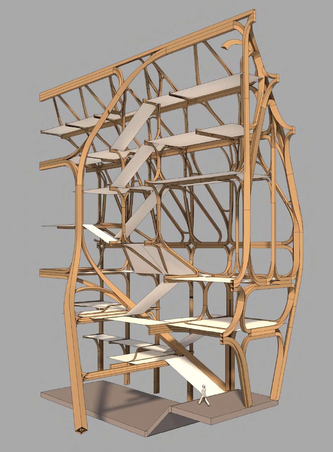
The structural expression of the glulam framing is structural and decorative. The project aims to find a way to express this structure both internally and externally.

55
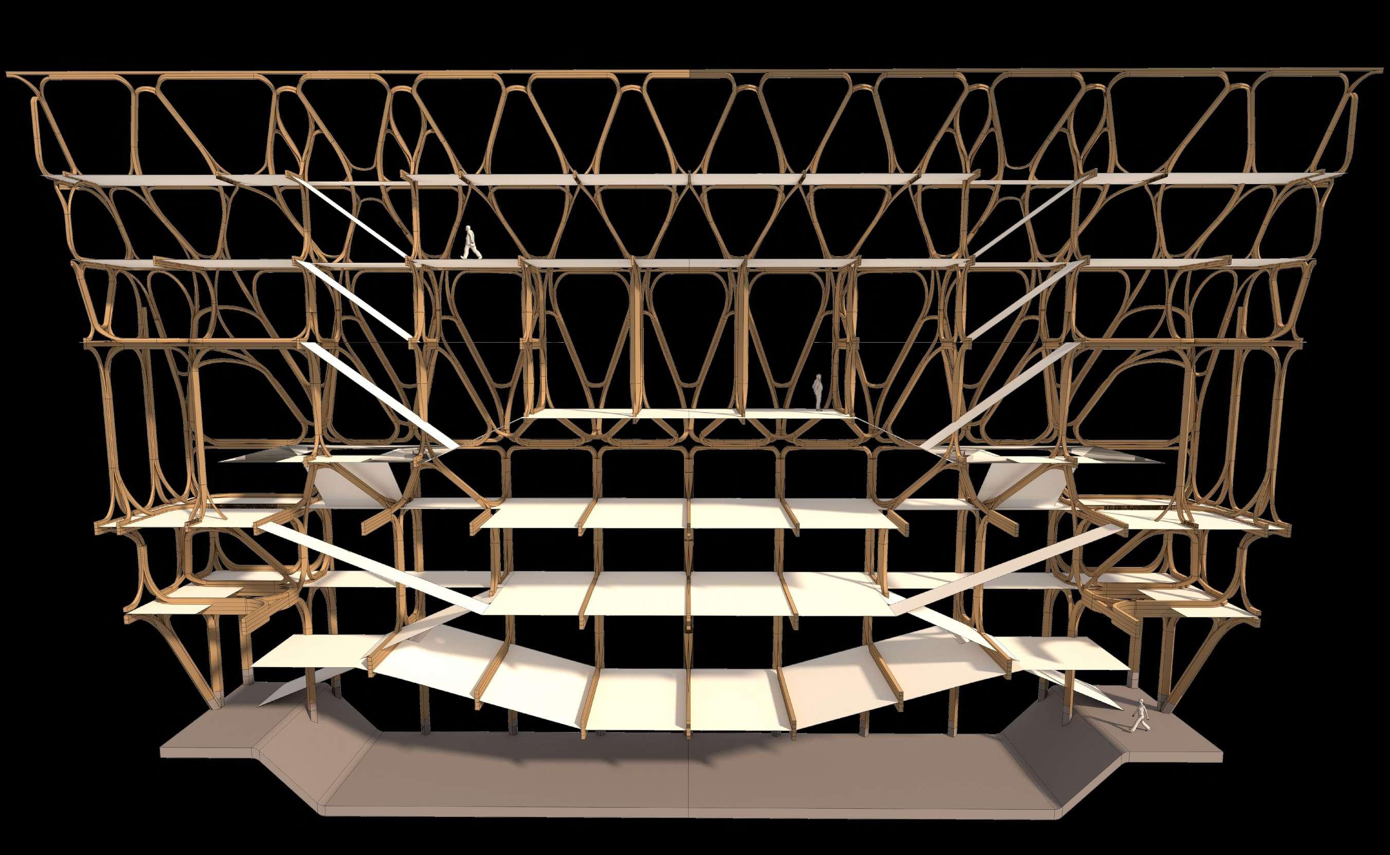
56 57 Structural model: Iteration 01 Sectional view shows spaces organised in stacked fashion, structure weaving between.

58 59 Structural model: Iteration 02 Sectional view showing introduction of hall space with transfer structure to transfer loads above
Utilising low thermal conductivity of
Facade System and Openings Concept Study
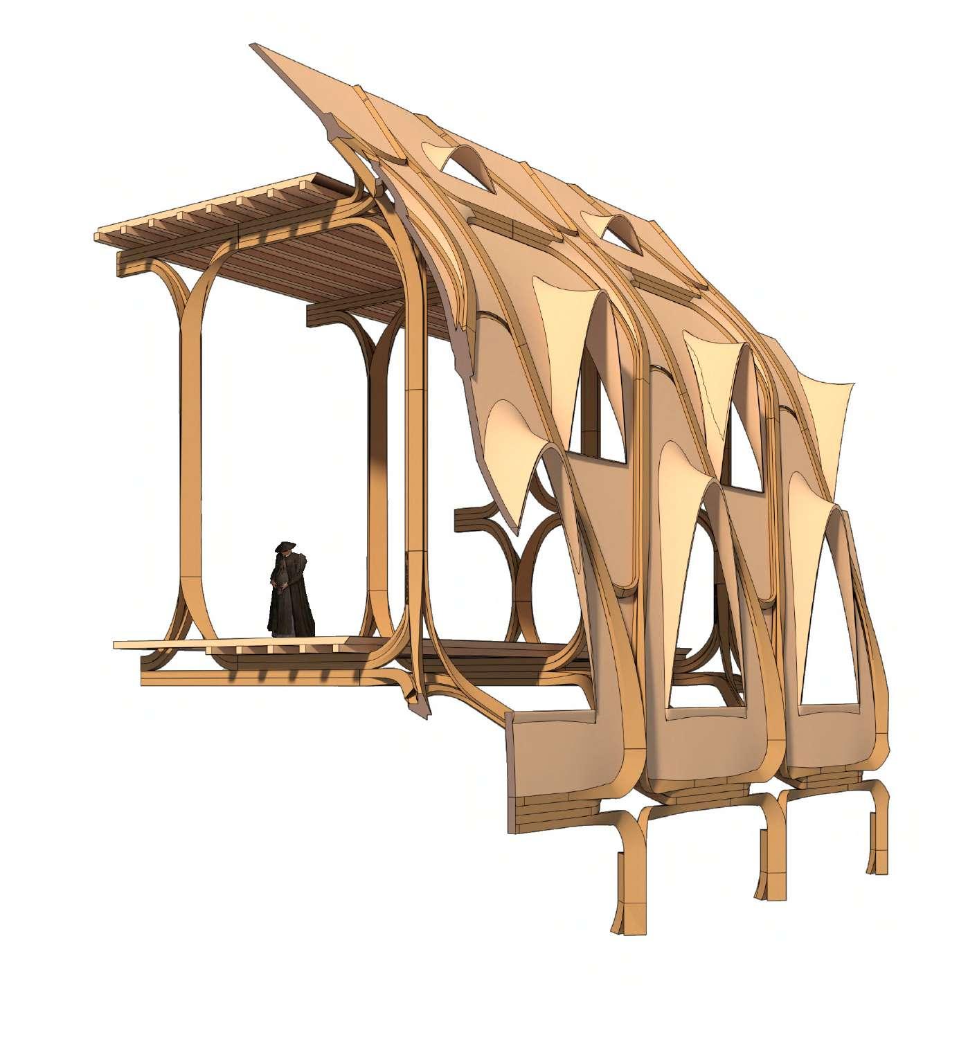
The project investigates the possibility of a timber face with expressed structure, oweing to the lower thermal conductivity of timber as a material. Current forms of engineered timber could in this instance develop a new kind of expression, both in reference to past and contemporary building practices.
60
1. Timber structure expressed externally
2. Parabolic dormer openings within timber infill panel
timber
2.
1.
61
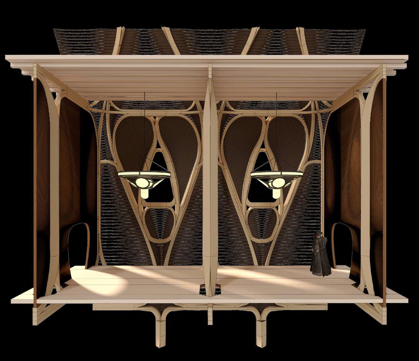
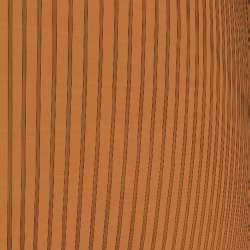
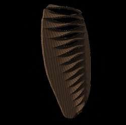
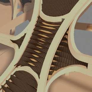
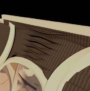
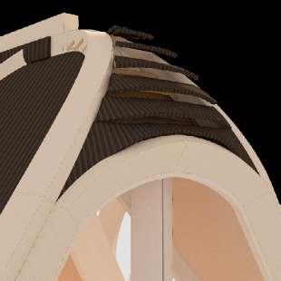
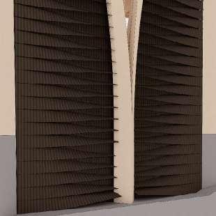
Cladding System: internal view Infill strategy imagined as a louvred or slatted system, charred to resist weather with both external and internal spatial implications.
1. Ornamental internal panelling using high value timber species
2. Charred external louvres
3, Lighting and servicing integration
Utilising low thermal conductivity of timber Charred external timber finish lends durability
Durable timber products employed within lamination
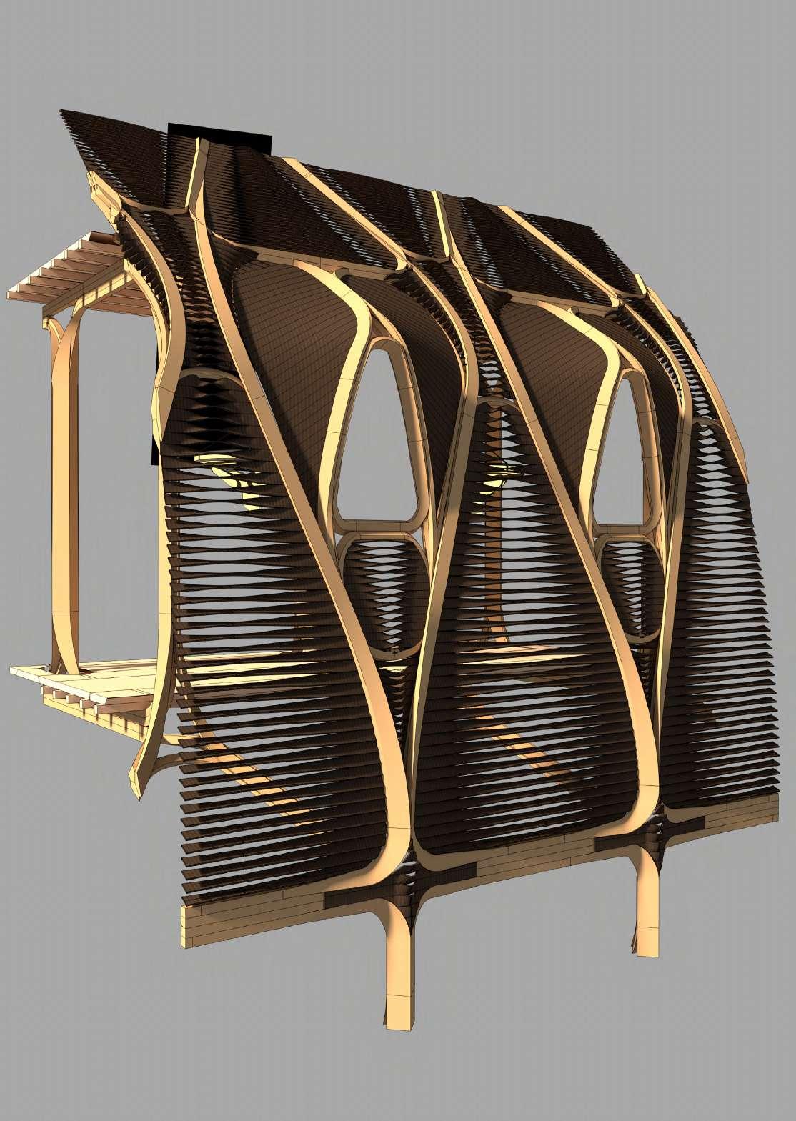
Cladding System: external view
Different processes for achieving timber’s durability are employed in the facade system. Forms of chemical alteration to age old techniques like charring timbers create weatherproof envelope with expressed timber structure.
Twisted louvres respond to solar shading requirements
62
summer winter
Highly differenciated species distribution not currently employed in engineered timber
unstocked temporarily 260.477 hectares
Larch 307.050 hectares
Pine 2.420.623hectares
Douglas Fir 217.614 hectares
Fir1.1182.757 hectares
Spruce 2,763,219 hectares

Harnessing Timber’s Complexity and Availability
Oak 1.129.706 hectares
Beech 1.680.072 hectares
Long life deciduououss ie Maple, ash, chestnut, lime, white beam, balck locust, elm 769.578 hectares
Short life deciduous ie birch, alder, poplar, cherry, rowan, willow, forest fruit trees 1.147.904 hectares
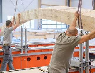
The project aims to make full use of available timber resources in Germany. It proposes a method of timber manufacture making use of local species as well as fast grown plantation timber in challenge to typical contemporary practices. It also aims to tap into the available manufacturing landscape in Germany, Austria and Switzerland are the leading manufacturers.


63
Glulam manufacture CLT manufacture
33%
Employment of locally available timber species and labour
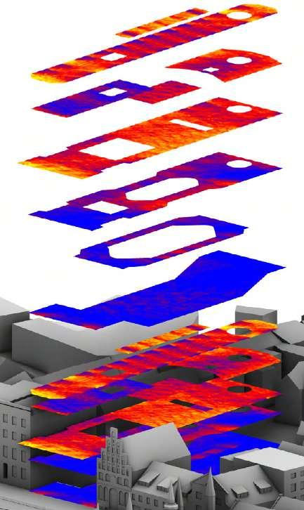
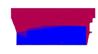
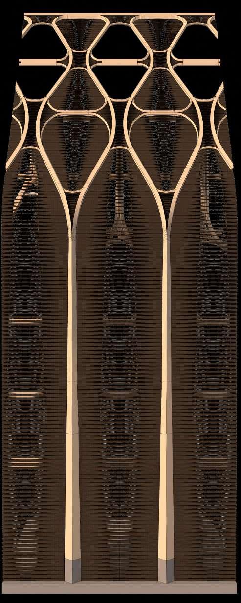
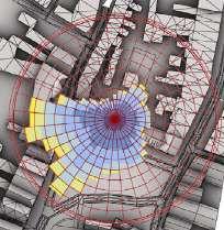
Different levels of glazed vs solid infill were tested for the facade design. Solar gain analysis revealed the larger glazed openings to be a viable option. Louvre’s are limited to ventilation panels in the building’s intelligent facade.
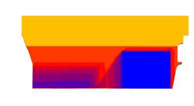

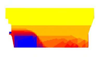

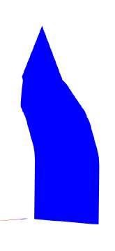

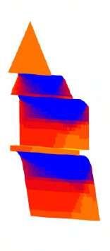
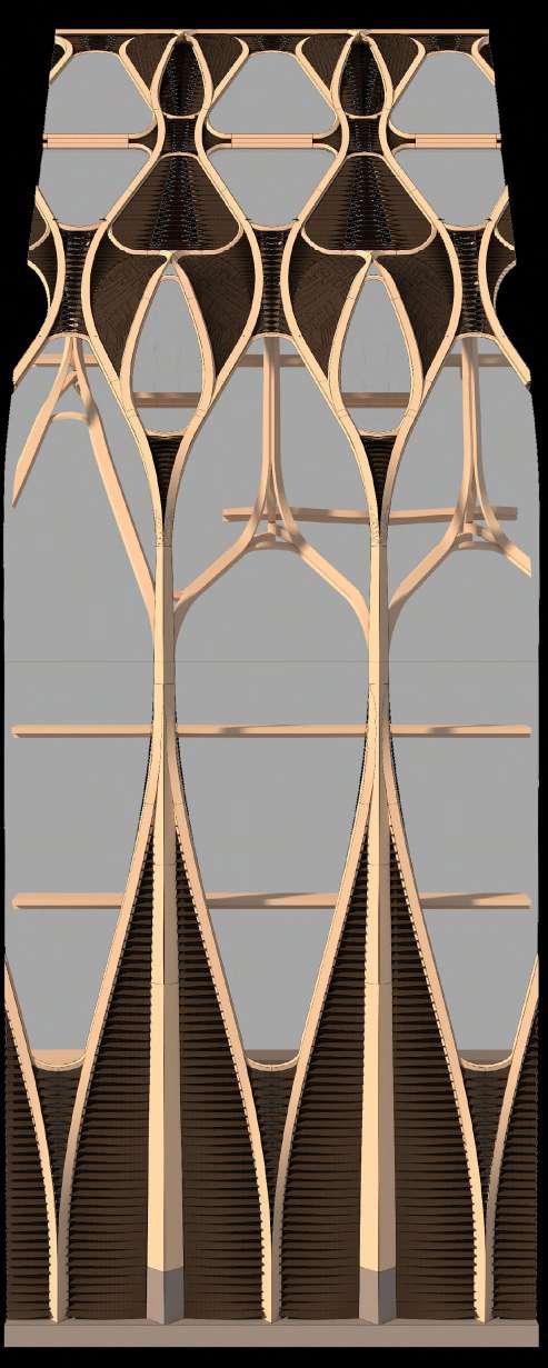
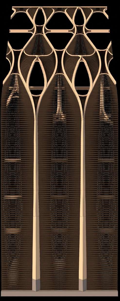
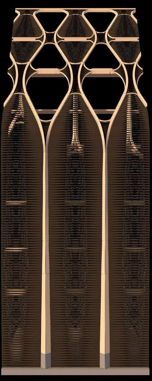
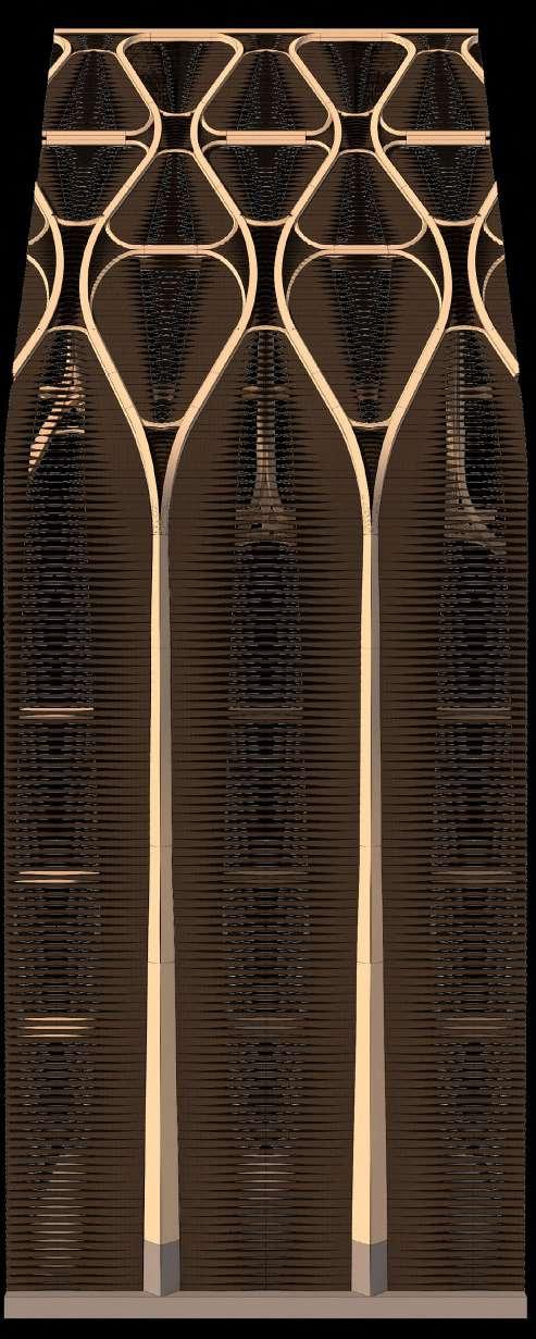
64 65 Stepping facade helps to mitigate direct sunlight therefore
larger glazed
without high heat gain Summer Winter Direct sunlight hours on facade on winter solstice Direct sunlight hours on facade on summer solstice 0 0 12 6 front front rear rear west elevation west elevation east elevation east elevation Daylight hours analysis on summer solstice shows limited direct solar gain throughout building allowing for larger glazed infills Facade iterations
enabling
areas
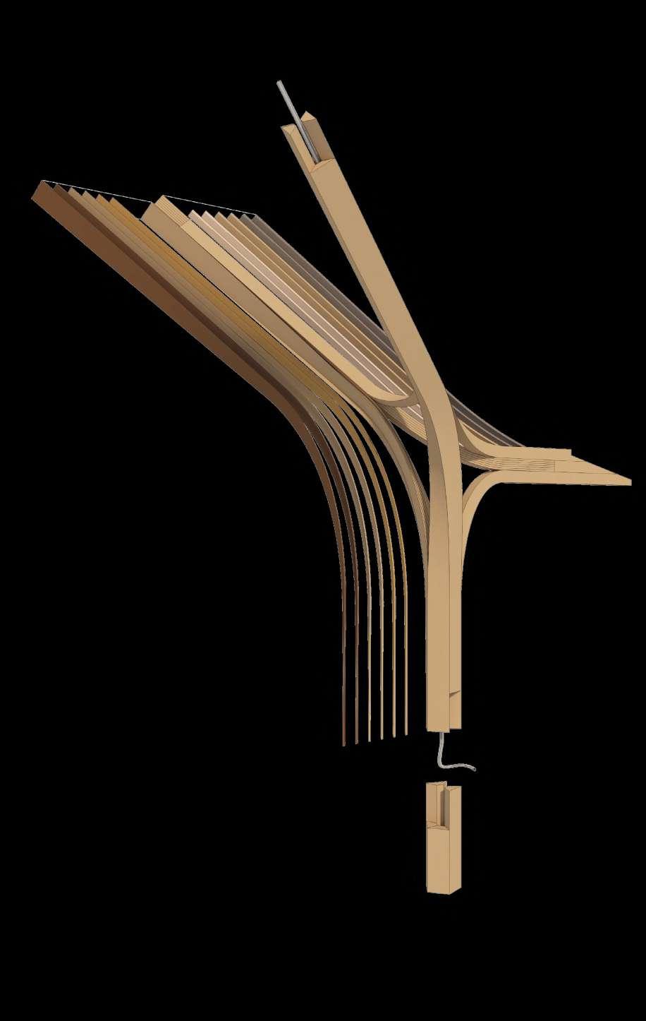
1. Servicing integrated to component: central cavity
2. 'Scarf' connection varies between bundled types
3. External lamination: Highly durable engineered wood (e.g. Kebony, Acoja)
4. Internal lamination: fast grown, lower value/less durable timbers under less strain (e.g. thinnings or juvenile wood)
5. Intermediate lamination: slow grown softwood (e.g. spruce, pine)
6. Decorative Internally exposed layer: sumptuous hardwoods create rich internal environments for the guildhouse (e.g. cherry, walnut)
1. High Performance eg. Oak Highly Durable and decorative N.B. Engineered durable timber outperforms
2. Intermediate performance eg. Mature Spruce Fast Growing, widely available

3. Low performance eg. Spruce thinning Waste product with less strength
Differenciated Lamination
4. Rare/Decorative eg. Cherry Prized luxurious material used as panel finish
To cope with the requirement of structural expression the lamination is made up of different timber species and types of engineered wood, allowing their properties to be suitably employed: a new kind of laminated product. The layers of the lamination can serve functionally and decoratively.
66
6. 5. 4.
3.
2.
1.
1.
3. Interleaving of small and large lamellae within elements
lamella thickness = r/200 = 12.7
Bend radius = 2540mm
6. Single curved element with high curvature thin lamellae integrated between thicker ones
lamella thickness = r/200 in bent area = 5mm
Bend radius = 1050mm
Bend radius 1 = 1600mm
Bend radius 2 = 3450mm
lamella thickness = r/200 in bent area = 8mm x 17mm
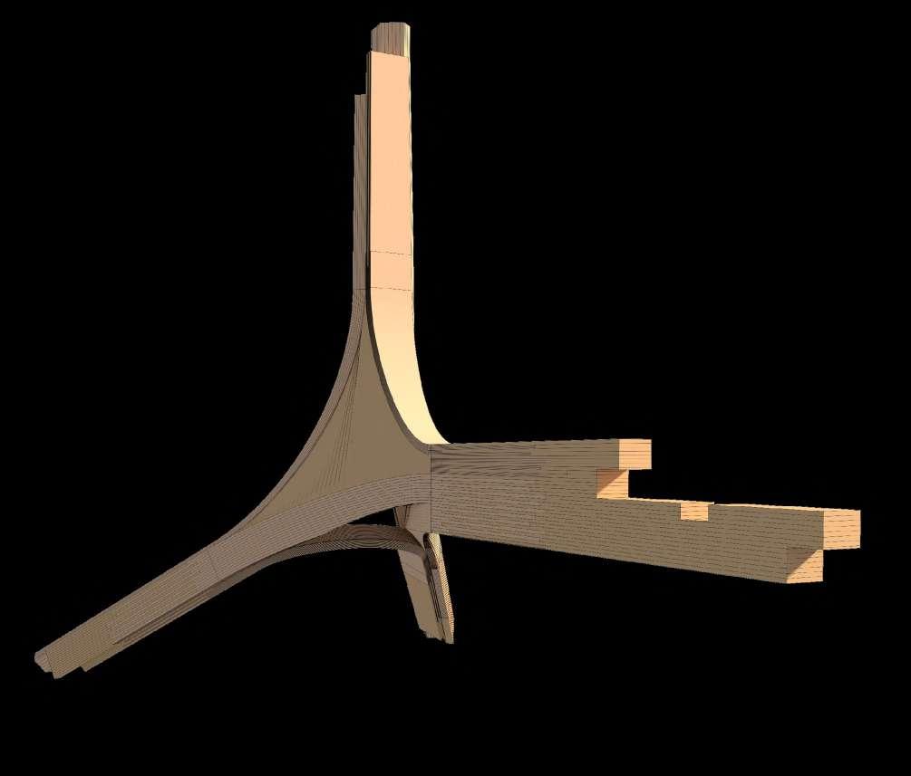
Lamination approach for single node
Continuous lamella logic creates a series of different nodal conditions throughout the building. Structural heirarchy is introduced as the members thin as one progresses upwards.
lamella thickness = r/200 in bent area = 3mm
67
1.
2.
3.
5.
6.
4.
Single curved elements with integrated twist
4. Single curved element with twist and integrated high curvature lamellae
2. CLT panel infill provides targeted structural support
5. Double curved element integrated with straight lamellae
Concentrations of tesnion and compression revealed through structural analysis evoke comparisons with structural optimisation in trees
Tension Compression
Optimised placement of timber species and lamella widths within lamination: heterogeneous material distribution
lamellae with high compressive strength (e.g. oak, larch, douglas fir) in areas of compression
tree’s natural growth of tension wood on the tensile side of the branch
durability
Medium durability
Low durability
High durability
50 years + 10-25 years >10 years
Accoyya (radiata pine)
Accoya (alder)
European Oak, Western red cedar cedar sweet chestnut yew mahogany douglas Fir Siberian Larch, cherry walnut
External Cladding
Internal finishes, decorative
european larch, elm, scotspine, pine SilverFir, norway spruce, pine, soft maple, european redwood, hickory, poplar European ash, willow, balsa, horse chestnut, sycamore, beech, sitka spruce, Birch, aspen, white spruce, american ash,
Internal finishes, durable
lamellae with high tensile strength (e.g. ash, elm) in areas of tension
Optimised distribution of higher grade timber in areas of greater stress
Compressive/tensile strength
areas of high curvature areas of low curvature
High strength, high grade
medium strength, high grade
Low strength, low grade
Elm, Maple, Oak, Ash, Larch, Black Locust,
lime, walnut, Douglas fir, Hemlock, white beam
can include other management strategies like coppice, thinnings, with high proportions of juvenile wood
Poplar, Willow, Birch, Alder, Rowan, Cherry, chestnut, Spruce, Fir, Pine, Cedar
External structure
High stress areas of structure

Low stress area of structure
Optimisation by timber species
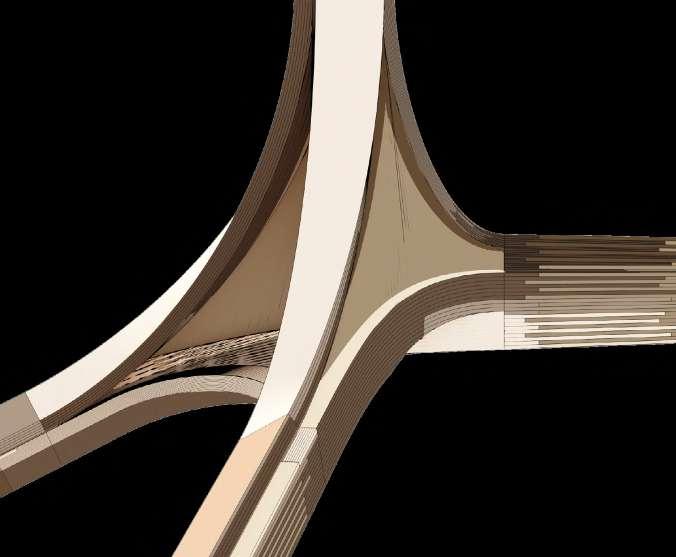
The proposed system aims to learn from the heterogeneous behaviour of trees to resist forces. Preliminary structural analysis gives an initial indication of force flows under typical live loading conditions. It is speculated that this could inform the distribution of different timber species and timber grades within the laminations.
68
Robotic operations carried out with bandsaw and endmill end effectors: larger pieces must be cut in 3 passes due to reach of robotic arm
Robotic
Blank types in the depicted assembly:
Single curved with tortion
Double curved
Single curved
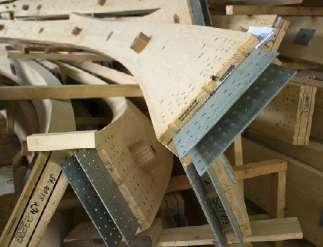
Robotic bandsaw cutting and milling Blanks are shaped with a robotic bandsaw operation while more conventional router milling operations are minimised to connection points. The bandsaw attachment is able to remove a large amount of material in a single pass. The robotic shaping process enables the mass production of the series of discrete elements in the building. Any blade slippages are celebrated as part of the experimental construction.
69
Preliminary Structural analysis of infill reinforcement of node through timber panels
Robotic drilling for bolted scarf connection
Robotic milling of joints
milling of light fixture cavities
Step 1: Multi-axis gluing of component blank
Step 4: Integration of services
Step 2: Series of different blanks created
Step 3: Machining of blanks to finished dimensions using robotic mounted bandsaw and endmill
Step 6: Series of different components ready for delivery to site
Step 5: Glued assembly of 6 discrete parts to form nodal component
Node types: re-interpretations of historic joints
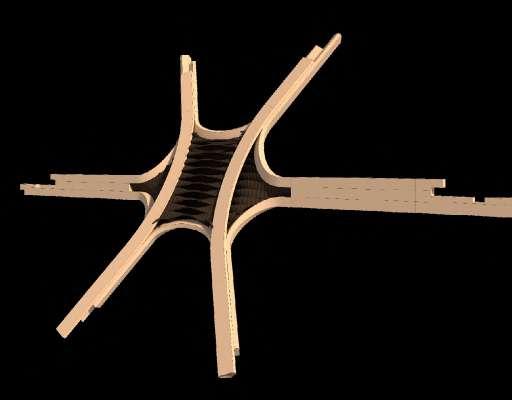
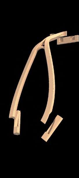
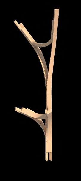
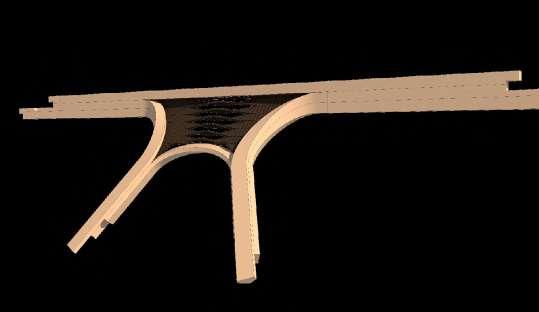
Historic timber frame details are re-interpreted in the proposed building system, celebrating the possibilities of glulam for structural inventiveness and innovation. Structural infill is inserted to strengthen the nodes depending on the size of nodal openings.




70
Purlin Junction Component 01
Component Purlin Junction Component 02
Branching post and beam element
Ridge Beam Junction
Cantilever component
Post and beam element
Nodal post and beam element
Dormer window component
Developing heirarchy
Structure purged to follow outlined logic and to generate more heirarchy


Bolted base connection
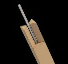
Bitumous paint applied to concrete surface within joint Servicing integrated into upstand Pre-cast servicing channel integrated to slab
71
1. Non-structural infill
2. Structural infill (shear walling)
Insulated timber infill panels received by structure
Servicing already integrated to components
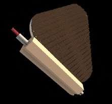
Notched receiving detail for timber panel
Some panels are integrated to timber elements at pre-fab stage and installed as one
Structural Bay Facade Fragment
Notched receiving detail for glazed panel Bolted site connection
Component based structure allows craning of individual components on site
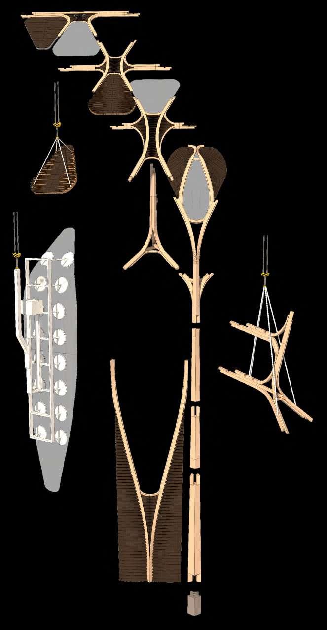

1. Ventilation panel infills enable active ventilation of building
2. Internal panelling species differenciation: spatial richness comes from richer, more costly final internal layers in the lamination. Infill panels perform insulative function.
3. Structural glazzing infills some of the openings between structure
4. Dormer openings provide variation to flat optings

5. Nodal glulam connections form main structure
6. On graduating to master title, guild members ceremonially carve their mark into the structure
View to internal spaces shows facade infill's relationship to structure and how spaces may be defined through thermally performative envelope
72
1.
4.
3.
2.
6.
Glulam structure externally and internally expressed durable modified timbers make up final lamination
Solid panel charred finish
Envelope strategy: Indicative external wall buildups (section view)
Charred external Louvres Steambent Douglas fir 20mm
Dampers for natural ventilation intake - motorised control
Perforated timber panel, red cedar (charred finish)
Charred external Douglas fir cladding ventilated to rear 20mm
Glulam Spruce/Fir/ Pine batten 50 x 50mm
OSB board 18mm
Breather membrane
200mm Woodfibre insulation between 100 x200 straight spruce noggings
Spruce soulplate 100mm x 200mm
Vapour barrier
Glazed infill panel
Durable lamellae external 40mm
Ventilation panel detail Solid panel detail
Ventilation panel steambent louvre, charred finish
Envelope strategy: Indicative external wall buildups (plan view)
Charred external cladding, Douglas Fir 20 x 200mm
Steambent to fit curvature
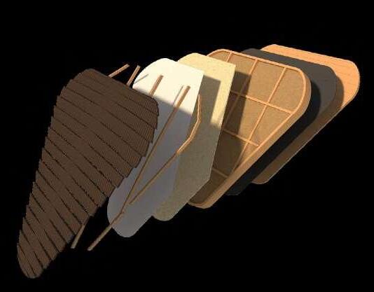
Spruce batten for cladding fixture 50 x 50mm
Vapour Barrier Main structure receives infill
CLT panel 100mm
internal lamellae
decorative timbers, fire retardant finish
Shaped Glulam main structural member 800 x 950mm
External lamellae of acetylated timber (accoya) with engineered weather resistance 40mm
OSB board 18mm
Insulated timber infill panel build-up (3D)

CLT internal panel 100mm
Shaped Glulam main structural member 380 x 330 mm
Decorative lamellae internal 40mm
Servicing cavity 500 x 300 mm
Internal lamellae decorative timbers, cherry, oak, elm
Breather membrane
Wood fibre insulation 200mm
Glulam studwork (coldbent) 100 x 200 mm
Lower build-up (large structural members with infill), panel inserted from above
member 380 x 330 mm
External acetylated lamellae
Build-up as structure thins toward top of building, panel inserted from exterior
Envelope Strategy: Facade Build-up
The building envelope is percieved as a re-interpretation of historic types where the loadbearing timber structure is expressed, owing to timber’s low thermal conductivity. The buildup employs different timber species/products based on their durability and aesthetic value. These form a discretized lamination in the main structure, infilled by insulated panels and glazed units. When solid, these lend some structural stability to the structure.
73
Double glazed fixed glass infill unit bolted into structure
Silicone infill allows for differential movement and watertight performance

4x laminated tempered glazing panel 20mm (cold bent if curved) outer layer with PVB interlayers
Aluminium spacer bar 20mm concealed internal bolted connection for solid panels
Steel L-profile fixes to post and holds clipping detail
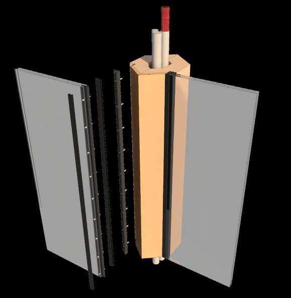
Servicing integration to component
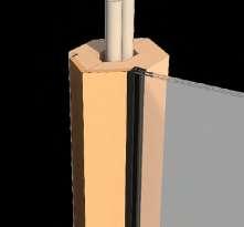
Timber post machined to receive glazing panel
steel clipping detail held between laminated glass panels
Silicone infilled to edge for watertightness and to allow for movement
External lamellae of acetylated timber (accoya) with engineered weather resistance
Servicing Integration
Large scale glazing infills are a challenging part of the scheme to manufacture. Keeping some panels infilled as solid has benefits for heat loss and gain, and the scheme looks to optimally infill with glazing as to provide appropriate sunlight levels throughout the building. To enable a seamless integration of glass panels between exposed timber structure a bespoke clipping detail has been developed for the building.
4x laminated tempered glazing panel 20mm (cold bent if curved) inner layer with PVB interlayers
Bolted connection to steel L Profile with bolted fixture to structure
74 Window Infill detail and insertion procedure
Large scale glazed panels fabrication procedure
01. flat float glass cut to shape
04. coldbent laminations are bonded with PVB interlayers to final thickness
02. glass sheets tempered in autoclave chamber for increased strength
05. edge clipping detail and spacer bead bonded to glass to form double glazed panel
03. individual laminations are cold bent over formwork
06. Panels craned into place on site following structure erection
Bolted connection detail
1. Low-Tech 01: Working with natural durability
Local timbers are distributed an used in the facade and interior as per natural characteristics (source: Inwood (Cymru) Ltd)
European ash, willow, balsa, horse chestnut, sycamore, beech, sitka spruce, Birch, aspen, white spruce, american ash, european lime, plane, alder
non-durable >5 years
Accoya (radiata pine) an Accoya (alder), tropical hardwoods
very durable 50 years+
2. Low-Tech 02: Charred Timbers make up external cladding. Douglas Fir is chosen for local availability and already high durability prior to charring. Charred timber can last 80+ years if well maintained
3. Low-Tech 03: Building Care by User
Similarly to the upkeep of historic timber frames the building is oiled with flaxseed oil every 3 years as a protective measure. Many historic exposed timber buildings in Germany are cared for in this way
slightly durable 5-10 years
durable 15-25 years
moderately durable 10-15 years
european larch elm, scotspine, pine SilverFir, norway spruce, pine, soft maple, european redwood, hickory, poplar Siberian Larch, cherry, walnut white oak, Sapele
European Oak Western red cedar, cedar, sweet chestnut, yew, mahogany, douglas Fir
3 year cycle
Louvred facade infills act as ventilation panels for internal comfort Cladding ventilated above breather membrane allows drying
Non-durable wood contains hydroxyls which are source of degradation
Acetic acid reacts with timber within heated chamber producing water as a waste product
Acetyl groups replace hydroxils creating stable product highly durable modified timbers as final lamination layer
Weatherproof Facade Design
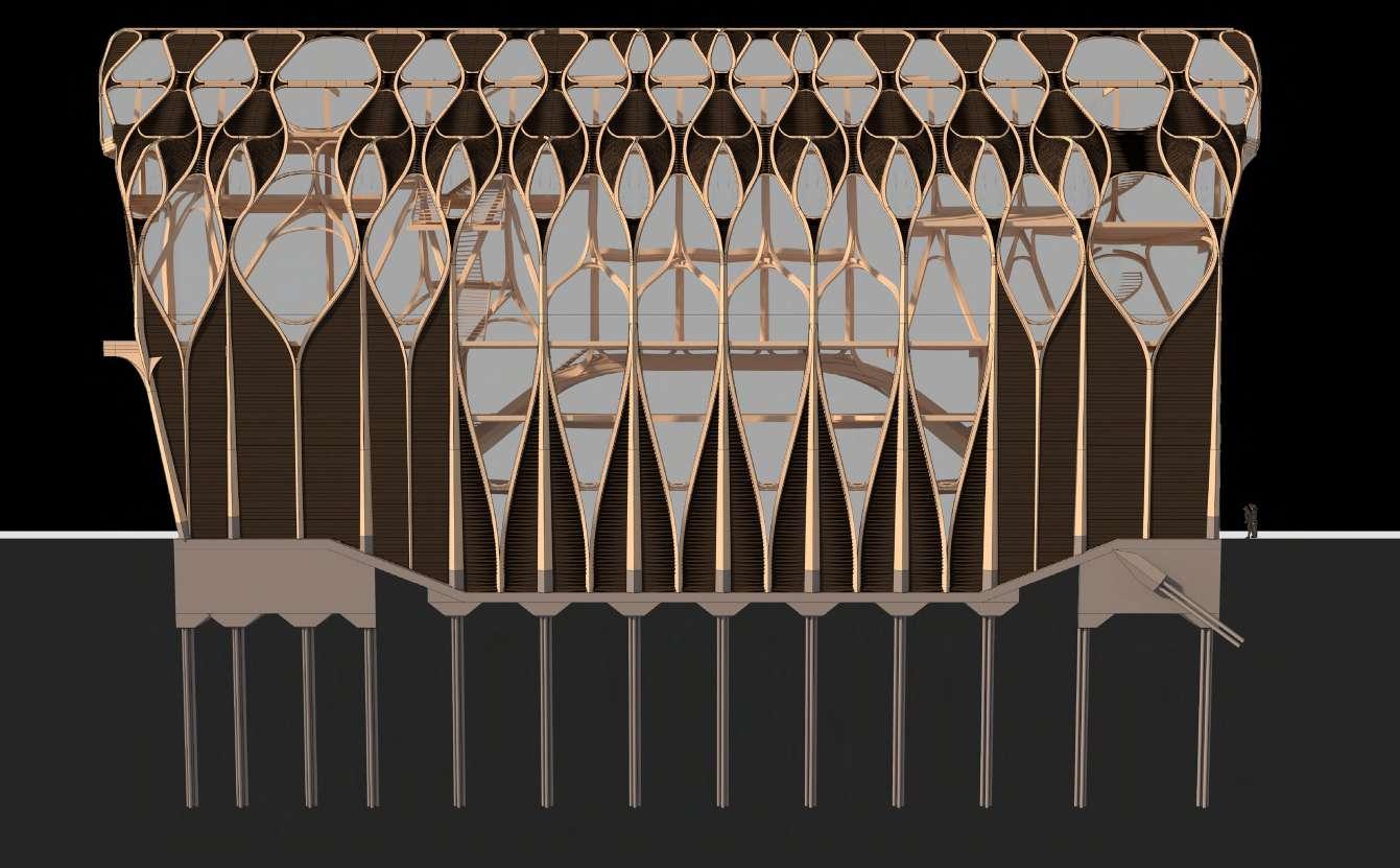
The building looks to leverage both historic and contemporary methods for timber durability in the facade design resulting a hybrid low and high tech approach. Processes requiring high energy input, like the production of modified timbers are limited to the structure members only. As a building for makers of timber buildings, it is assumed that the building will be well maintained, making the regular oiling of the facade a legitimate approach.
75
4. Low-Tech 04: Facade Ventilation
5. High-Tech 01: Accoya External laminations integrated to componentry. Molecular modification with waste product only of water (acetylation) and without biocides prevents timber degredation.
1.
2.
3.
5.
4.
optional fan assistance with very high heating load
Stale warm air released
wind direction informs cross ventilation approach
Ground level vent (100% intake)
Ventilation panel summer mode
hot stale air is exhausted through roof level vents
hot air from occupied spaces rises through stair atrium
cross ventilation from north to south
ground level vent air intakes provide fresh air
some coolth provided by thermal mass of concrete slab
dampers controlled to lower air intake in cooler months
mixed air released
Mid level vent (intake 80% , 20% release for cross ventilation)
Ventilation panel winter mode
stale air is exhausted through roof level vents
positive solar gain is enabled through stepped facade
cross ventilation from east to west mixed air cross ventilation from east to west
stale air from occupied spaces rises through stair atrium

hot air rises through the atrium space supplementing UFH
ground level vent air intakes provide fresh air
underfloor heating throughout the building radiates heat
Ventilation Strategy
High level vent (intake 80% , 20% release for cross ventilation)
Ridge level vent (100% release)
Rdige level vent (100% release)
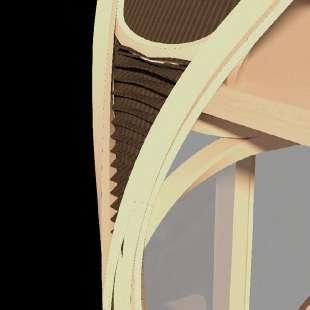
Natural ventilation is the key way in which fresh air is circulated both in the summer and winter months, enabling occupant comfort. The front stair atrium is utilised to circulate and release hot and stale air from the top of the building. The facade is designed with a series of louvred vents with air-tight dampers within them. These can control the amount of air intaken and released depending on internal demand
76
Stale
fresh
intake cold
air-tight
intake
release hot
Winter mode Summer mode Facade Vent types. Dampers control air intake and release
cool air
air intake
dampers control
and
water loop heats incoming draught
Oak flooring finish for durability
CLT panel with integrated underfloor heating 50mm
Servicing integrated between joists 60x150mm
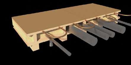
Cellulose insulation for acoustics 150mm
CLT panel 50mm
Straight glulam floor beam 120x120mm
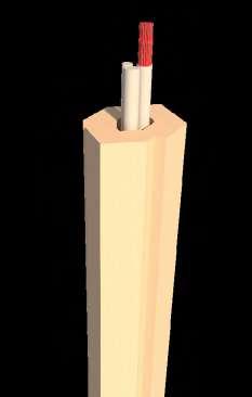
floor build-up and servicing integration
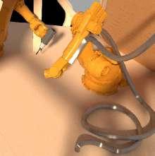
1. Glass lift core with service riser and vaccuum based extract system for workshop direct link to biomass storage
2. Precast service channel integrated to floor slab
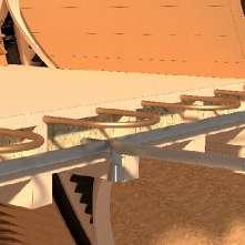
3. Main connection to water main and electrics
4. Underfloor heating throughout building integrated to floor slab
5. Sprinkler integration to floor panels
6. Main thermal stores 1,500L
7. Mechanical control panel
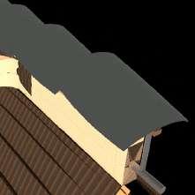
8. Photovoltaic system concealed on ridge line rated capacity 29kW
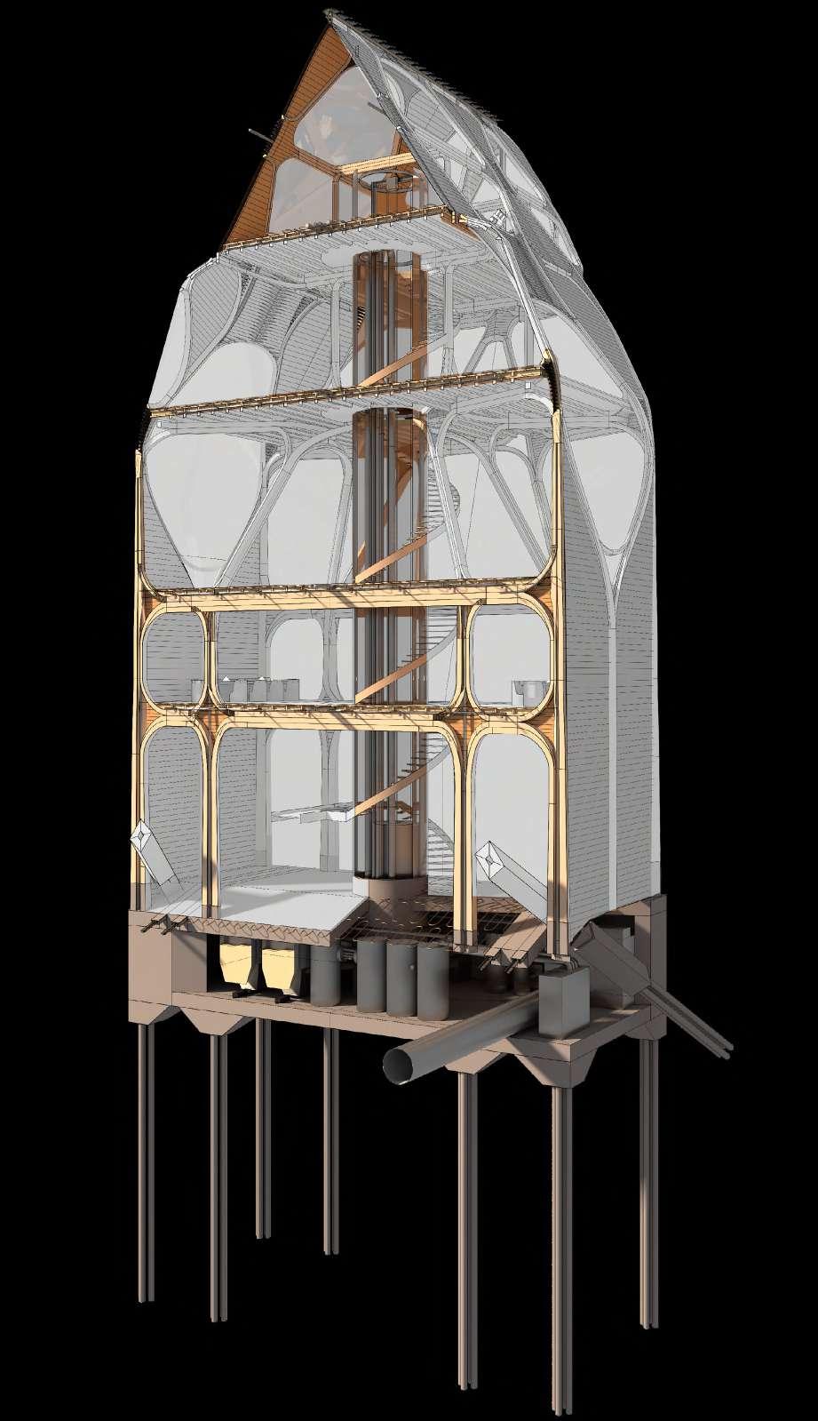
Servicing Integration
The prefabricated nature of the building’s delivery allows for the seamless integration of services . These guts of the building are housed in basement plant rooms and distributed through the hollow spaces in the prefabricated components. The service riser within the lift core allows for the integration of dust extraction for the upper workshop space feeding directly into the biomass boiler system.
Smaller services ie electrics run within void
77
Solar panels located on ridge line help to power the building
sawdust extraction run through lift shaft accessed through floor
sprikler system and underfloor heating integrated to floor panel
in structural members
2.
3.
4.
5.
6.
7.
8.
1.
section 4
final drawings
78
79
New Figure
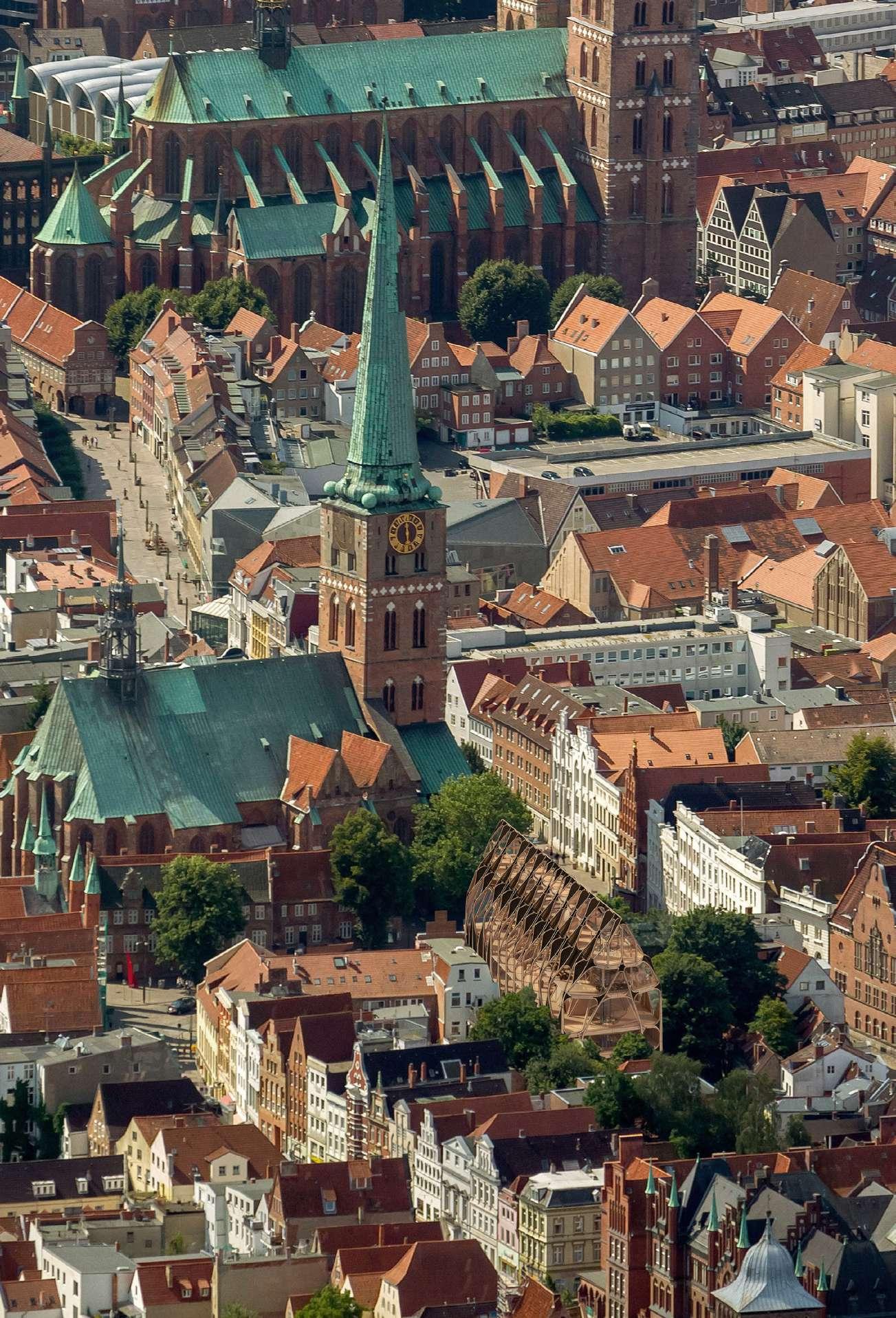
The gable end figure of the Guildhouse chimes with the existing context. As a figure it pokes above the streetscape, yet remains respectful in scale against St Jakobi church, which still dominates the Koberg Square.

80 81
Civic Presence
The new gable evokes the strong civic presence of the former guildhouses in its relationship to the cty square. Glazed openings provide views to the structure and activity within.
1. Solid infill panel with external Douglas Fir charred finish, internal lamella cherry 300mm
2. Ventilation infill panel. red cedar charred finish external and internal with concealed dampers 300mm
3. Cantilever node supports front balcony
4. Glazed handrail to balcony
5. Walnut and Oak finish front door with panel inlays 3m height
6. Lower shear walling adjoining existing party wall 350mm
7. Existing adjoining building underpinned with auger piling
8. Front feature staircase, Oak finish fixed to floor plate
9. CLT stability infill panel to main transfer structure 300mm
10. Main hall transfer structure 950x950mm 23m span, hardwood finish by local availability
11. Front facade glazed panel with seamless clipping detail
12. Guild sigil carved to floor in front lobby
A Gable Amoung Gables The stepped facade further invites a relationship to the street while referencing the historic gable end type which dominates Lübeck’s cityscape.
1.
2.
4.
12.
5.
6.
7.
8.
9.
3.
10.
11.
rear facade option glazed
rear facade option infilled

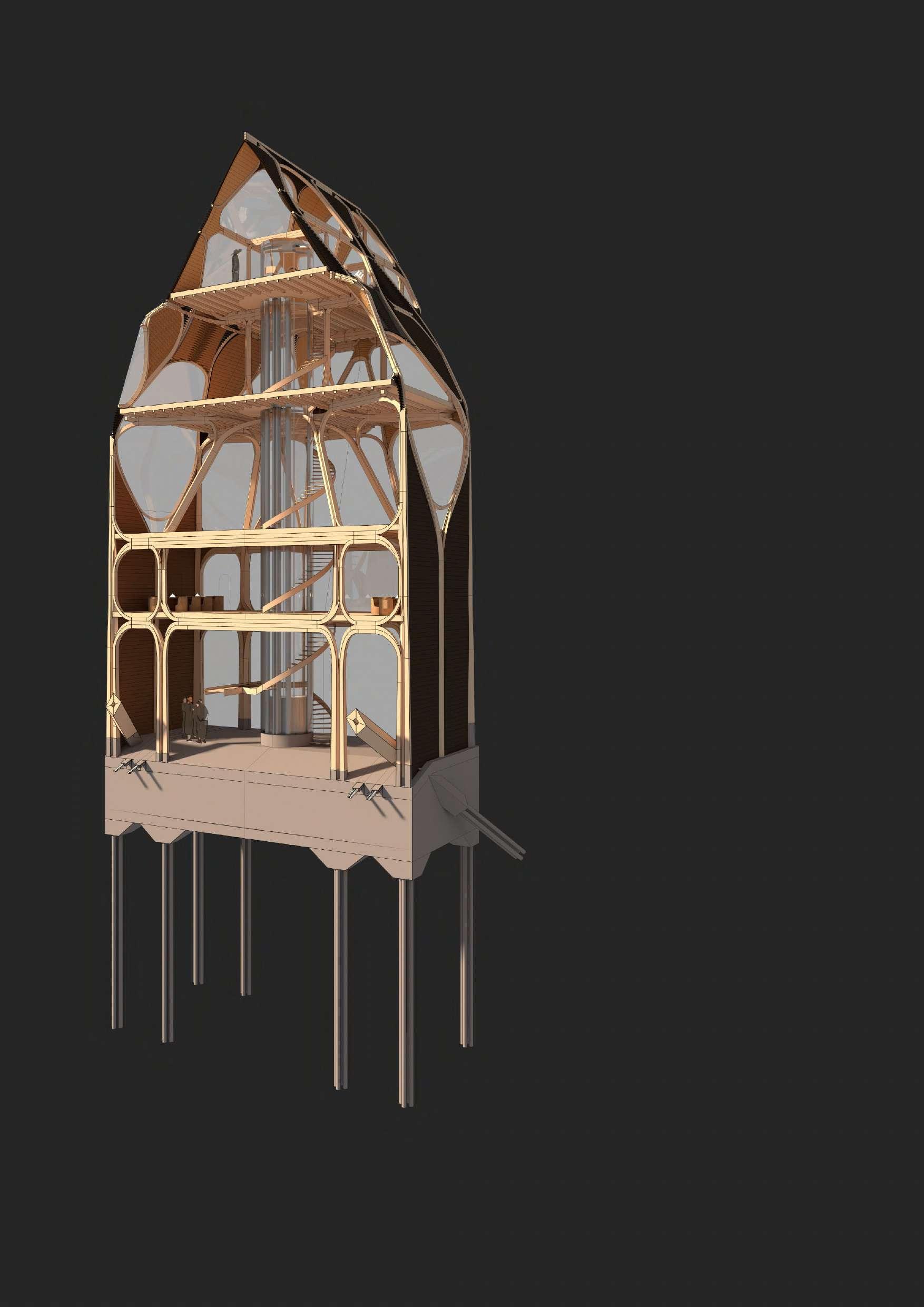
1. Glass lift core with service riser and vaccuum based extract system for workshop
2. Fireproof glazed partitions between meetign chambers
3. Cedar charred finish ventilation louvres
4. Main column with servicing integrated in cavity 500mmx500mm
5. Main hall transfer structure base 950 x 950mm
6. Precast service channel integrated to floor slab
7. Pile cap 400mm and 10m pile foundation to clay soil
8. Pile foundation for main transfer structure 5m
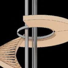
Steel ring beam fixing detail
Rear building service core and meeting rooms
The lift core at the rear of the building functions as a service riser and utility stair. The spiral option is chose due to the constrained vertical nature of the building’s organisation. Seamless integration of servicing is designed into the intelligent structure.
Rear stair constructed around lift rails
 1.
2.
3.
4.
5.
6.
7.
8.
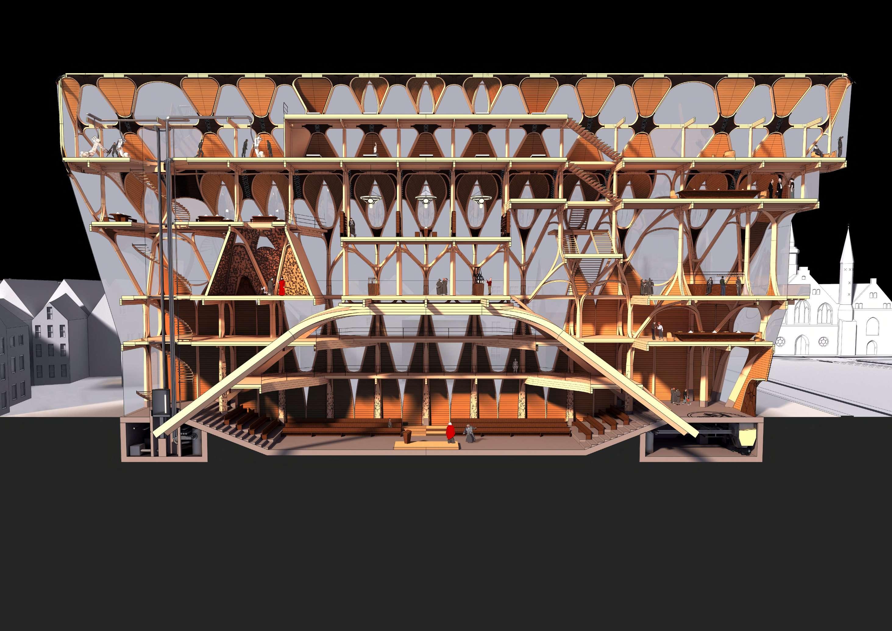


1. Front foyer with access to feature stair 2. Main meeting room 3. Public Bar 4. Secondary meeting rooms and offices 5. Journeyman hostel: recreation room 6. Main Chamber 7. Exhibition Space 8. Craft library and reading rooms 9. Ceremonial Chamber and Timber species archive 10. Reading room 2 and study area 11. Prototyping workshop 12. Journneyman’s
sleeping quarters 13. Rear foyer with access to lift and
yard 14. Basement
diagram
interrelation of transfer vs
and
structures A. Primary 01 post and beam interface B. Primary 02 branching post C. Transfer 01: post to transfer D. Transfer 02 transfer node E. Stability 01: infilled node A. B. C. 14. 1. 6. 7. 8. 9. 10. 11. 12. 13.
hostel
rear
plant rooms Structural
shows
post
beam
5. 4. 3.
2.
D.
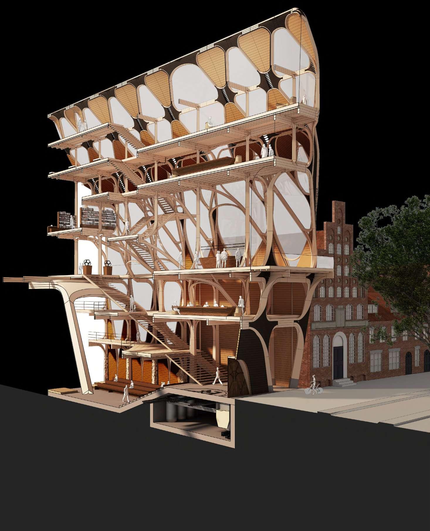
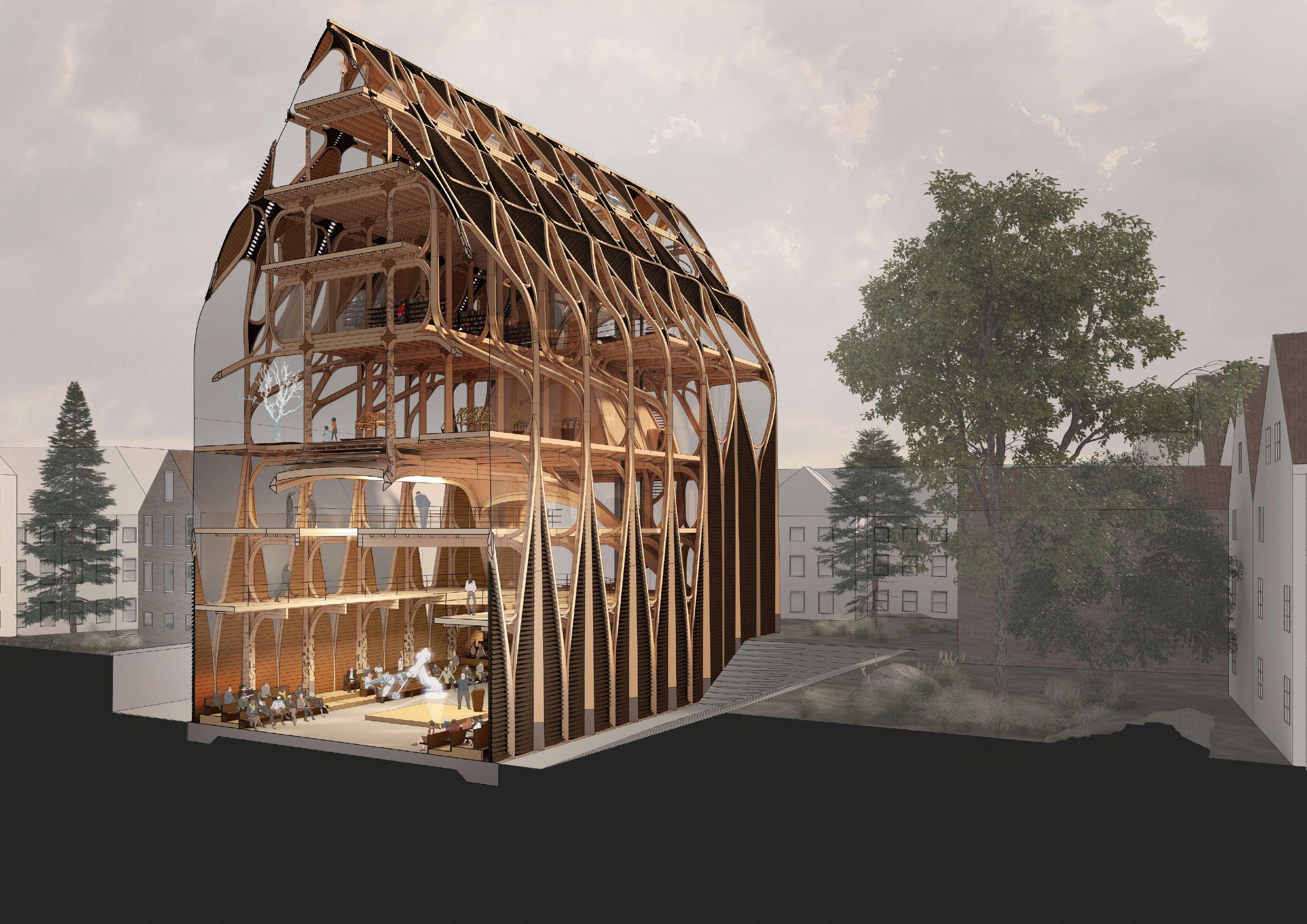
Porousity to urban square Section reveals series of rooms structured around central hall with a relationship to the street, all with an expressive formal architecture in the developed system. The diverse timber finishes and carvings celebrate the building’s crafting and the local materials available.

86 87
Transfer Structure
The building is designed around a series of generous circulation spaces which allow for the collision of guild and public life, surrounded and enabled by the expressive timber structure. The main transfer structure is intended as a feature point of the building.

88 89
Building Entrance and Feature Stair
The front staircase accentuates the axiality of the building, drawing users up to the public level above. A siteline is also offered through the building revealing its activity. Here, at the bottom of the building the structure is thick, and the weight of the vertical structure above can be felt.

90
Knowledge accumulation and exchange
An archive documenting timber species and their properties is contained in the upper reaches of the building, helping to preserve both new and former timber craft knowledge.
91
Public Ritual
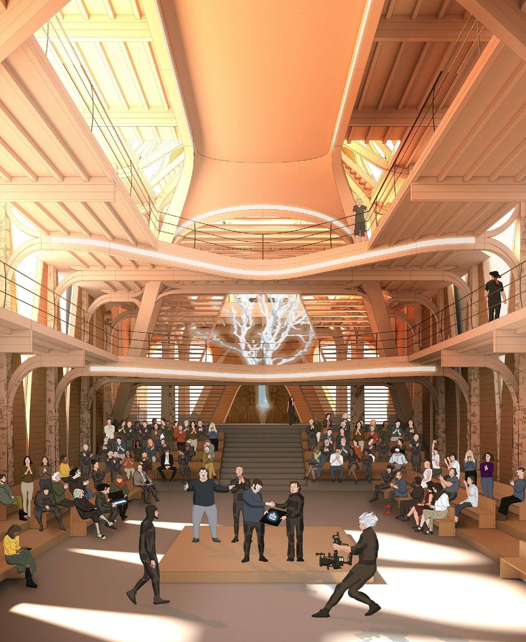
The main chamber is intended as an extension of the square, enabling both public and guild assembly for lectures, apprentice graduations, debates on guild policy or other events.
 A space for gathering and celebrating craft
The building fulfils both a public and private function, enabling the collision of guild and public life. It is a place for celebrating the cultural value of craft in the city once again.
94 appendix general arrangement drawings
96 97 0 2m 5m 10m 25m Section AA Section bb Section cc Location Plan Scale 1:500 at A2
98 99 Appendix 6 6 7 7 8 8 9 9 10 10 11 11 12 12 ffl 6.64 level 2 gallery ffl 2.88 level 1 gallery ffl 0.00 ground level ffl -2.87 lower ground ffl 6.00 bsmt ffl 10.63 level 3 ffl 15.70 level 3 mezzanine ffl 17.00 level 4 (front) ffl 19.00 level 4 (rear) ffl 22.50 level 5 ffl 26.10 level 5 mezzanine el 29.51 ridge 1 1 2 2 3 3 4 4 5 5 Section AA Scale 1:125 at A2
100 101 Appendix Ground floor plan. Scale 1:200 at A2 1 1 a b e f 2 2 3 3 4 4 5 5 6 6 Section AA a b e f 7 7 8 8 9 9 10 10 11 11 12 12 Section BB Section BB Section CC Section CC 0 2m 5m 10m 25m Section AA Main Assembly chamber Rear Stair Lobby Rear gardens Ground floor plan Scale 1:200 at A2
102 103 Appendix 5.3 Level 2 floor plan. Scale 1:200 at A2 1 1 a c d f 2 2 3 3 4 4 5 5 6 6 Section AA a c d f 7 7 8 8 9 9 10 10 11 11 12 12 Section BB Section BB Section CC 0 2m 5m 10m 25m Section CC Bar/tavern Exhibition space Staircase Atrium Ceremonial chamber WC WC Section AA Level 2 floor plan Scale 1:200 at A2
104 Appendix 5.5 Short Section BB. Scale 1:200 at A2 ffl 6.64 level 2 gallery ffl 2.88 level 1 gallery ffl 0.00 ground level ffl 10.63 level 3 ffl 15.70 level 3 mezzanine ffl 17.00 level 4 (front) ffl 19.00 level 4 (rear) ffl 22.50 level 5 ffl 26.10 level 5 mezzanine el 29.51 ridge A A B B C C D D E E F F 0 2m 5m 10m 25m Short Section BB Scale 1:200 at A2 Through Front Staircase
105 Appendix 5.6 Short Section cc. Scale 1:200 at A2 ffl 6.64 level 2 gallery ffl 2.88 level 1 gallery ffl 0.00 ground level ffl 10.63 level 3 ffl 15.70 level 3 mezzanine ffl 17.00 level 4 (front) ffl 19.00 level 4 (rear) ffl 22.50 level 5 ffl 26.10 level 5 mezzanine el 29.51 ridge A A B B C C D D E E F F 0 2m 5m 10m 25m ffl -2.87 lower ground Short Section CC Scale 1:200 at A2 Through central chamber
All work produced by Unit 14
Unit book design by Charlie Harriswww.bartlett.ucl.ac.uk/architecture
Copyright 2021
The Bartlett School of Architecture, UCL All rights reserved.

No part of this publication may be reproduced or transmited in any form or by any means, electronic or mechanical, including photocopy, recording or any information storage and retreival system without permission in writing from the publisher.

-

@unit14_ucl UNIT


 Cover design by Charlie Harris

 LÜBECK, GERMANY


 1.
2.
3.
4.
5.
6.
7.
8.


 A space for gathering and celebrating craft
The building fulfils both a public and private function, enabling the collision of guild and public life. It is a place for celebrating the cultural value of craft in the city once again.


