SUMO_X

The project explores the structural potential of folding an OSB (oriented strand board) plates system to design a robotic sumo wrestling arena in Tokyo, Japan. A layering strategy is adopted on the folding plates to maximise structural efficiency and reduce material waste.


Japan has a long history of timber construction. During the 2021 Tokyo Olympic Games, different strategies for reducing carbon emissions in the building industry were investigated for the construction of new sports venues and renovation of the existing ones. Therefore, adopting OSB in the design of the new arena is a valid response to the historic material context in Tokyo and the urgent need for a sustainable approach to the new urban infrastructure.
While Japan has been facing the challenges of an ageing society and social isolation across different generations, the proposal of a robotic arena aims to provide novel entertaining experiences for the audience and explore a new typology for the sports arena after the COVID-19 pandemic.
CHENRU SUNG YEAR 5
SUMO ARENA WITH FOLDING OSB PLATES SYSTEM
TOKYO, JAPAN
Y5 CS
COMPARISON OF CHINESE AND WESTERN ROOF STRUCTURE
While the traditional Chinese roof structure is highly constrained by the span of the beams or number of the columns, the Western truss system allows long-span structure to be achieved with a combination of relatively short segments.
 Traditional Domestic Building in Northern China, Roof supported by stepped beams
Traditional Domestic Building in Southern China, Roof supported by columns directly
Western Truss System
MONUMENTAL TIMBER-FRAME BUILDINGS: ORDER

0 5 10 15 20(m) 0 1 2 3 4 5(m) 0 1 2 3 4 5(m) 0 1 2 3 4 5(m) 0 5 10 15 20(m) 0 5 10 15 20(m)
& SCALE
The monumental architecture follows a strict order that the number of tiers of Dougong increases with the scale of the building.
Main Hall, Fo Kuang Temple Main Hall, Shan Hua Temple Main Entrance Gateway, Tu Le Temple


 CHONG MING TEMPLE: CANTILEVERED BEAM
Different from temples of similar size, Chong Ming Temple adopts the highest tier of Dougong to support the cantilevered beam that spans across the temple.


0 1 2 3 4 5(m) 0 5 10(m)
CHONG MING TEMPLE: CANTILEVERED BEAM
Different from temples of similar size, Chong Ming Temple adopts the highest tier of Dougong to support the cantilevered beam that spans across the temple.
Stage 1: Existing structure


Stage 2: Lower beam removed
Stage 3: Top-tiered Dougong removed
Stage 4: Cantilevered beam removed
STRUCTURAL ANALYSIS OF CHONG MING TEMPLE
The structural analysis of Chong Ming Temple is conducted in Karamba to simulate the load distribution under different conditions and exam the structural efficiency of different components.


 WESTMINSTER HALL: HAMMER BEAM WITH RIB ARCH
Westminster Hall adopts hammer beams as the main roof structure which enables it to span across over 25m.


 WESTMINSTER HALL: RIB ARCH & MASONRY WALL
A set of rib arches is integrated with hammer beams to transfer the load to the corbels. By lowering the roof structure, the self-weight of the masonry wall resists the lateral force.
RECLAIMED STRUCTURAL TIMBER: REUSING & CASCADING


Reusing and cascading are the two main approaches to handling reclaimed structural timbers. When the reclaimed structural timbers cannot be reused directly, a proposal is made here to use reclaimed structural timbers as the “raw material” for the glulam beam.


 Reclaimed Structural Timber
Cascading of Structural Timber
1. Raw Material
2. Production of Slats
Floor Board
Glulam Beam Reclaimed ?
Window Frame Board
OSB
Plywood
MDP
MDF Pocket Farm, Norway, by SCS
3. Drying
4. Sorting according to Strength
5. Finger-jointing
6. Planing of Slats
7. Application of Glue
8. Gluing under Pressure
9. Planing of Glulam Product
STRUCTURAL CONCEPT: TRUSS + FOLDING PANELS
A combined system of truss and folding panels is proposed to reduce the sizes required for truss in the long span structure and optimize the use of materials for panels by replacing the diagonal members of the truss with folding panels.

ARTEFACT 1: INVERTED ROOF TRUSS


0 5 10 20m
An inverted roof truss is adopted here as the primary framework to guide the arrangement of folding panels, showing the potential of the combined system in an asymmetrical structure.


0 5 10 20m
ARTEFACT 2: HIP ROOF TRUSS
A hip roof truss with high roof space is adopted to highlight the spatial experience generated by the folding panels and prove the potential to create habitable roof space in this setting for users.
ARTEFACT 3: SCISSORS TRUSS

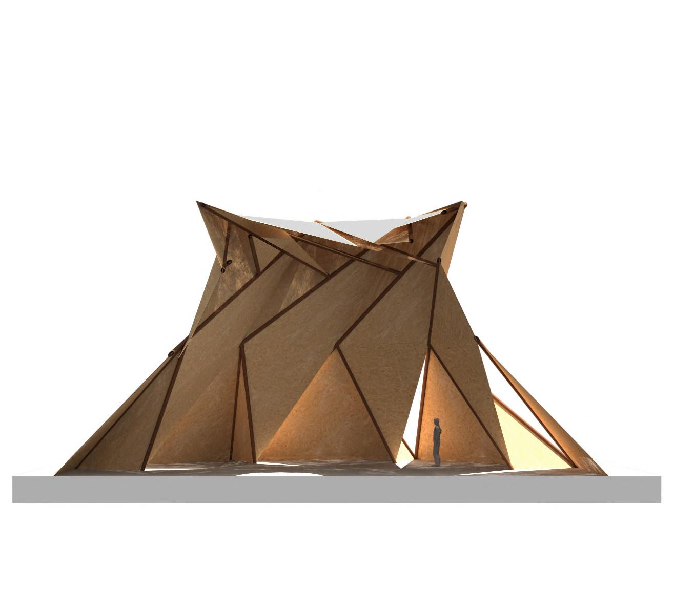
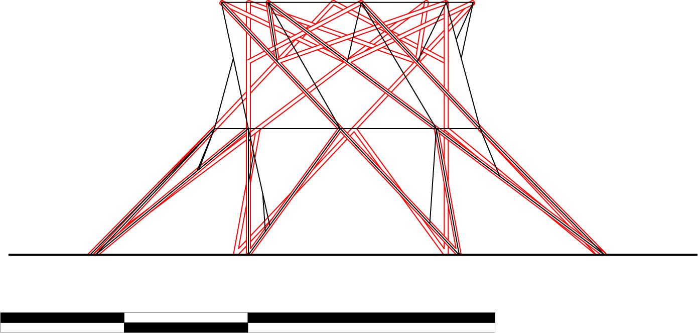
A scissors truss with supporting columns is developed to explore the integration of roof, columns and envelope. The flexibility to arrange the bracing members for columns also allows different extents of openness for the envelope on different sides.


0 5 10 20m

0 5 10 20m 0 5 10 20m
ARTEFACT 4: RECIPROCAL FRAME
A polygonal reciprocal frame combined with folding panels is adopted to explore the relationship of reciprocal structural arrangement with envelope and skylight.
FOLDING PATTERNS: OVERVIEW
A physical model study of folding structure is conducted to understand different folding principles and obtain hands-on experience of folding techniques. Folding Techniques for Designers by Paul Jackson is used as a reference for folding patterns.

Translation: A motif is repeated exactly in one direction.
Reflection:
A motif is repeated exactly in one direction, but each time as a mirror image of the preceding motif.
Reflection:
A motif is repeated exactly in one direction, but each time as a mirror image of the preceding motif.
Glide Reflection:
A motif is translated and reflected, not necessarily in a straight line.

FOLDING PATTERN: TYPES & DIRECTIONS


Four basic folding patterns are illustrated with diagrams, showing the lines of “valley fold” and “mountain fold” respectively. Models show different spatial experience generated by the folding structure and their bending directions resulting from the folding patterns.


Stretch:
A square, when stretched in one specific direction, will create a rectangle. Depending on the original crease pattern, the pattern will transform differently if stretched vertically or horizontally, or it will transform in the same way in whichever direction it is stretched.
ARTEFACT: STRETCHED CANOPY
The folding technique of “vertical stretch” is adopted to generate the basic folding patterns. The diagonal pattern allows the paper to stretch along the direction and generate a canopy with two support points, where two edges of the paper meet the ground.


Strand Dimension:
Length, standard length 80-120mm
Width, standard width 10-12mm
Thickness, standard thickness 0.9-1mm

Parametres:
Slenderness Ratio: Length/ Thickness
Characteristic of Thinness: Length/ Thickness+Width


Specific surface: Active surface area for gluing


Species: Softwood/ Hardwood
Commonly used British Timbers


Softwoods: Spruce, Pine, Larch, Douglas fir
Hardwoods: Oak, Sweet chestnut
FOLDING PATTERNS: OVERVIEW
A physical model study of folding structure is conducted to understand different folding principles and obtain hands-on experience of folding techniques. Folding Techniques for Designers by Paul Jackson is used as a reference for folding patterns.
Front Layer Back Layer Core Layer
Density kg/m3 Modulus of Rupture N/mm2 Modulus of Elasticity N/mm2 Internal Bond N/mm2 Hardwood1 Hardwood1 Hardwood1 Hardwood1 Hardwood2 Hardwood2 Hardwood2 Hardwood2 Softwood1 Solid Wood OSB Softwood1 Softwood1 Softwood1 Softwood2 Softwood2 Softwood2 Softwood2 l w d Minor Axis Minor Axis Boiled Major Axis Major Axis Dried
FOLDING & FRAMING STRUCTURAL PRINCIPLES
Truss-line model and shell surface model are simulated in Karamba to understand the load distribution and allocate frames and folding panels accordingly. Folding panels with optimized material distribution are used at the area where loads are significant.


FRAGMENT: MULTI-FLOOR FOLDING STRUCTURE


This artefact extends the folding principle from the roof structure to the supporting structure underneath, creating a multi-floor structure. The second artefact explores how to integrate the folding structure with landscape when there is a level difference at two ends.


FRAGMENT: MULTI-FLOOR FOLDING STRUCTURE


This artefact combines the previous two modules, demonstrating the potential and flexibility to extend the structure by combining different modules. The second artefact adopts a non-parallel frame and revolves it to create a circular structure. Different openings are created on both floors.

ARTEFACT: ENCLOSURE


 This artefact explores a triple floor structure and starts to apply enclosure to form subdivided space.
ARTEFACT: TRANSITION
This artefact combines two types of structural modules with different levels together, exploring the transitional space from a large open area to a more subdivided space.


ARTEFACT: COMBINATION
Based on the previous artefact, this artefact further combines two grid systems together, from a parallel grid to a revolving one. It demonstrates the flexibility to adapt to different site conditions.


ARTEFACT: COMBINATION
Based on the previous artefact, this artefact further combines two grid systems together, from a parallel grid to a revolving one. It demonstrates the flexibility to adapt to different site conditions.


FRAGMENT: MODULE 1


 The fragment explores how the folding panels transit to vertical columns using the same layering strategy.
FRAGMENT: MODULE 2
The second fragment applies vertical support continuously across different levels.


FRAGMENT: MODULE 3
 The third fragment explores the possibility to adopt vertical support across several bays to achieve a longer span. The dimensions of columns vary based on the floor to ceiling height, showing the hierarchy of space.
FRAGMENT: ROOF & ENCLOSURE

 The roof adopts a curved form with a deep overhang and both ends tilted up. It is inspired by traditional Japanese architecture. Skylights are arranged to cast shadows on the folded surfaces of the envelope.
FRAGMENT: EXTENDED VIEWING CIRCLE


This fragment explores a new type of undulating seating plan. The seats on the periphery are turned 180 degrees to face an extended viewing circle. It also creates smaller viewing clusters which provide a more intimate and private experience.


BRIEF: URBAN NETWORKS
 Tokyo has dense networks of both highways and railways that spread across the great Tokyo area and connect to the land reclamation area directly. Ariake, in the centre of land reclamation area, is the new sub central business district of Tokyo.
Highway Railway
Proposed Site
Tokyo International Airport
BRIEF: LAND RECLAMATION AND OLYMPICS
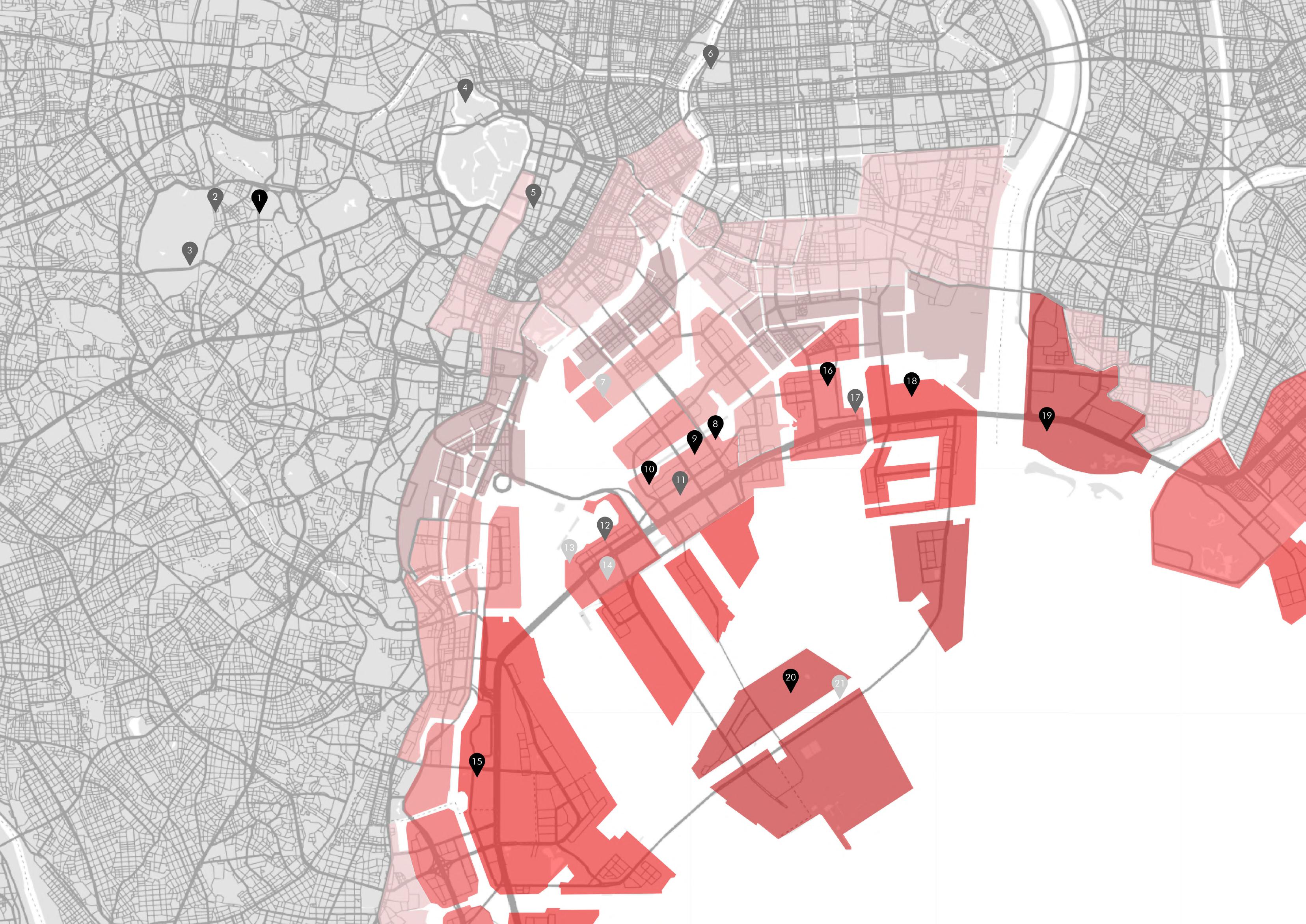
Tokyo has a long history of land reclamation because of its adjacency to Tokyo Bay and the concentration of urban development in the Great Tokyo area. During the 2021 Tokyo Olympic Games, most of the new-built and temporary sports venues were located in land reclamation area.


New-built Renovated Temporary
1985-1996
1976-1985
1966-1975

1946-1965
1926-1945
1868-1925
1603-1867
2021 TOKYO OLYMPICS STADIUM VENUES
LAND RECLAMATION OF TOKYO AT TOKYO BAY AREA


NOH THEATRE
Noh is a major form of classical Japanese dance drama that has been performed since the 14th century. It is the oldest major theatre art that is still regularly performed today.


NOH THEATRE
The traditional Noh Theatre is an outdoor theatre with the stage facing two sides. In In Praise of Shadow, the essential condition of Noh Theatre was described as “...that the stage be left in the darkness in which it has stood since antiquity.”
0 2 4 6
Mirror Room
8 10m Bridge Stage


 RYOGOKU SUMO HALL
0 20 40 60 80 100m Main Entrance Existing Sumo Hall 150mm 150mm 150mm Proposed New Stadium 1F Plan
Ryogoku Sumo Hall is an indoor sporting arena located in Sumida in Tokyo. It is mainly used for sumo wrestling tournaments and also house a museum about sumo.
すみません

Sumimasen. Excuse me.
生まれて、 すみません
Sorry for my existence.
NOT BOTHERING OTHERS
A “SUPER SOLO SOCIETY”
BRIEF: A SUPER SOLO SOCIETY
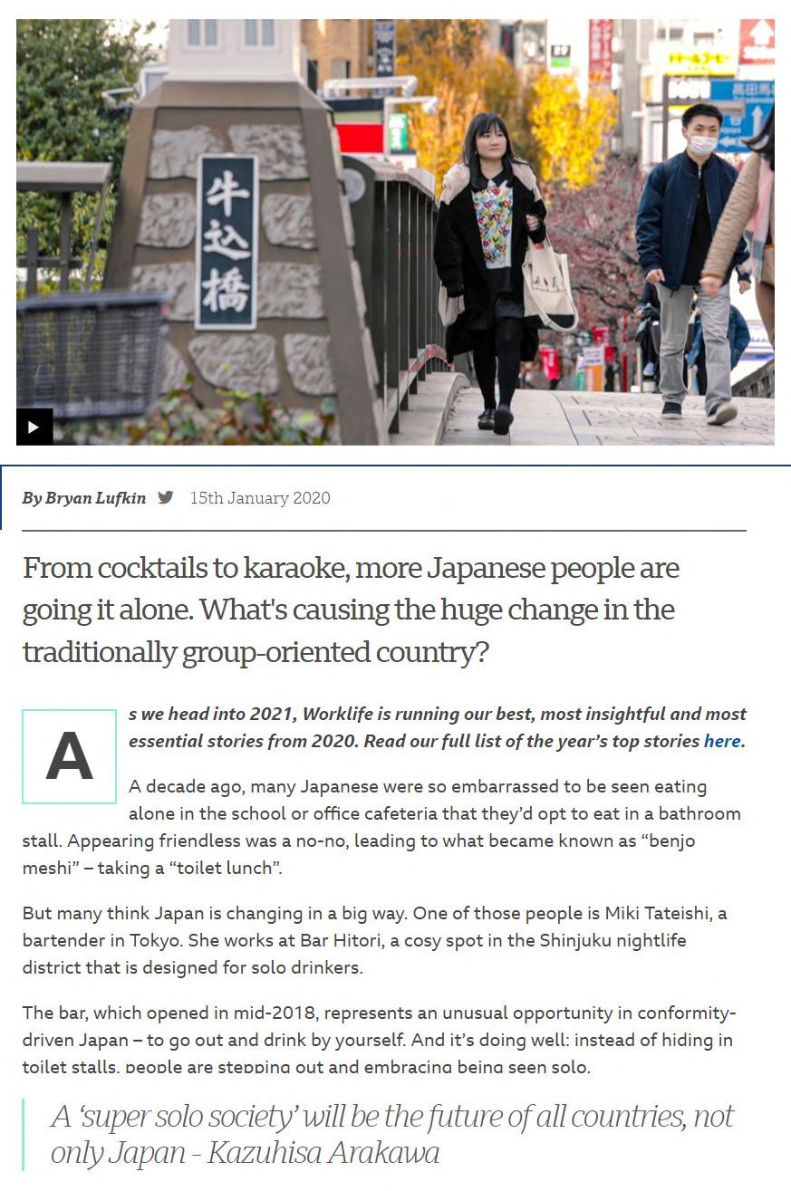
The idea of “not bothering others” is deeply rooted in the Japanese culture and serves as one of the most important guidelines for daily practice. However, this culture also poses great stress on individual and prevent people from forming a community.



FROM FLOW OF INFORMATION TO SPECTRUM OF HYBRID SOCIALIZATION
TRAIN STATION
INTERACTIVE EXPERIENCE - THE PATH TO BECOME A SUMO WRESTLER


BRIEF: SPECTRUM OF HYBRID SOCIALIZATION


The programs include a train station, an interactive path, a sumo hall, an area for hybrid dining and an area for meditation. The overall form gains inspiration from Plan for Tokyo proposed by Kenzo Tange.
FREEDOM AND SOLITUDE
 SUMO ARENA
Sentient Controlled

Human Mechanic
Ability
BRIEF: HISTORY OF ROBOT ANIME IN JAPAN


Appearance
Japan has a long history of robot anime from the 1950s. The types of robots in the anime can be categorized according to their abilities and appearances. While in the 1980s, a wide spectrum of robot animes can be observed, in the 2000s, the robot characters follow the tendency to be sentient and human-like.


2000
Astro Boy, 1952
1950 1980
Gundam, 1979
Mahoromatic, 1999
Gigantor, 1956
Transformer, 1984 Angelic Layer, 1999
Doraemon, 1969
Ghost in the Shell, 1989 Beatless, 2011
Cutie Honey, 1973
Future GPX Cyber Formular, 1991
Plastic Meomry, 2015
BIREF: ROBOTIC SUMO WRESTLING
The statistic shows clearly that the popularity of sumo has decreased dramatically since the 1990s. By introducing robotic sumo wrestling, sumo wrestlers will have chances to compete with wrestlers from previous generations and the audience will be able to enjoy an amplified viewing experience.

Potential ROBOTIC Match
Percentage of Population in Japan Selecting Sumo as Favourite Sport to Watch 1997-2021 Famous Sumo Wrestlers in the History (Debut-Retired)
Potential Match
SECTION: RESPOND TO THE CHANGE OF SCALE


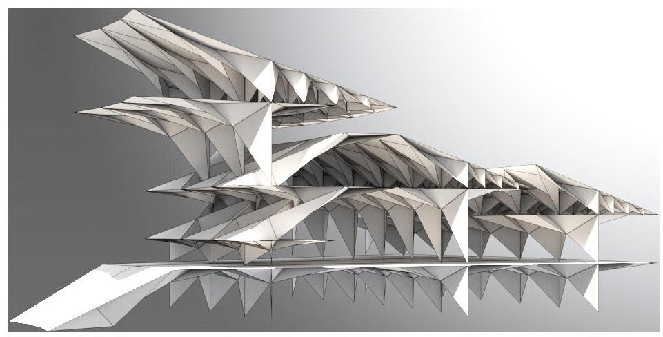
 Three iterations of the section are generated to respond to the change of scale in robotic sumo wrestling. The new condition gives more flexibility to arrange floors differently.
SECTION: SUBDIVIDED ZONES


 A series of studies is conducted by combining different modules. By alternating different modules, subdivided zones and small clusters of seating start to form.
GLOBAL MASSING

The global massing adopts a radiant form, responding to the different urban conditions and accomodating the major programme, the sumo arena. The overlapping of roofs is inspired by traditional architecture in Japan.


PROGRAMMES & CIRCULATION
Sumo arena

Dormitory for wrestlers
Foyer
Food and Retail
Robots display and maintenance
Pedestrian bridge /hologram display
Existing train station
Circulation for vehicles
Circulation for pedestrians
The sumo arena locates in the centre of the site, surrounded by other programmes in different scales. The main entrance is opposite to the existing train station and underneath a highway to attract visitors and activate the grey space underneath the highway.
OVERALL STRUCTURAL STRATEGY
The overall structural grid follows the radial form. The stadium is fully shaded with the roof held up by a compression ring and direct vertical support. Together the folding panels and layering columns form both the vertical support and horizontal bracing members.

OVERALL STRUCTURAL STRATEGY
The overall structural grid follows the radial form. The stadium is fully shaded with the roof held up by a compression ring and direct vertical support. Together the folding panels and layering columns form both the vertical support and horizontal bracing members.

 FRAGMENT: SUMO STADIUM
The rendering shows a partial view of sumo stadium which adopts the previous principles of subdivided folding panels and layering system.

 ARTEFACT: LONG SECTION
The long section demonstrates the long span roof structure, indoor sumo stadium and the pedestrian bridge underneath the highway.

 FRAGMENT: LONG SECTION
The section explores the ground condition to correspond to the program that requires high floor-to-ceiling space. The part extending to the waterfront faces outward to enjoy the sea view.
 FRAGMENT: CIRCULATION DECK
This view shows the circulation deck in-between the stadium, connecting programs on different floors. The circulation deck is partially shaded.


N
FORECOURT & MAIN ENTRANCE OF THE SUMO ARENA


N
VIEW FROM WATERFRONT SHOWING ROBOT DISPLAY & MAINTENANCE AREA AND DINING AREA ALONG THE SHORE


N
SUMO ARENA WITH THE HARBOUR VIEW


N
FOYER & URBAN GARDEN


N FOOD COURT & DINING AREA
MEETING ROOM FOR SPONSORS


N


N
EXTENDED VIEWING CIRCLE WITH ROBOTIC PERFORMANCES


N
DINING AREA ON THE WATERFRONT
Five main variables, the number of subdivisions, the proportion of subdivisions, middle support, end support and lower support, are defined to conduct the form finding analysis.


TYPICAL MODULE FORM FINDING
TYPICAL MODULE PANEL SUBDIVISION & LAYERING

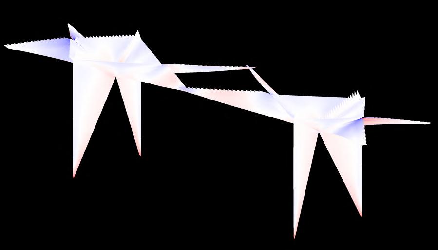


A size check is conducted before panel subdivision. In the case of typical module, the focus is on the recombination of the panels on one single OSB sheet. The key principle of panel layering is to redistribute the material from one single sheet according to the load distribution to improve the structural performance efficiently.


Ty1 D1:30mm D2:30mm D3:30mm Displacement: 6.49cm Ty2 D1:30mm D2:40mm D3:50mm Displacement: 3.35cm Ty3 D1:35mm D2:35mm D3:35mm Displacement: 4.77cm D1 D2 D3
Span: 50m
Slab thickness: 100mm
Primary Division: 0.5
Secondary Division: 0.5
Roof Height: 13m
Roof Height Difference: 0.5m
Displacement: 23cm
Parametric Model in Grasshopper
Primary Division: 0.3
Secondary Division: 0.7
Roof Height: 13m
Roof Height Difference: 0.7m
Displacement: 6.7cm
Variables for Long Span Roof
Primary Division: 0.7
Secondary Division: 0.3
Roof Height: 7m
Roof Height Difference: 0.3m
Displacement: 144.4cm

LONG SPAN ROOF FORM FINDING

The initial design intention is to have a stepped long-span roof to reduce the sense of scale compared with introducing a continuous long-span roof. Four variables are set while building the parametric models for form finding, including primary division, secondary division, roof height and roof height differences.


Primary Division Primary Division Secondary Division Secondary Division Secondary Division Secondary Division Roof Height (H1) Roof Height Difference (H2)
LONG SPAN ROOF PANEL SUBDIVISION
With the symmetrical structure and linear shape of the plates, it is manageable to combine or subdivide the panels in long span roof module. The balance among increasing subdivision to reduce material waste, decreasing subdivision to maintain structural strength and decreasing subdivision to simplify on-site assembly is carefully investigated.


Alternating Joints - Detailed Version (Non-planar)

Alternating Joints - Simplified Version (Planar)


JOINTS STUDY
 Panel 1
Two panels joined together
Three panels joined together
Four panels joined together
Panel 3 Panel 2 Panel 4 Removed material Tenon joints
The strategy of alternating the tenon and groove on three or four edges is proposed based on the typical tenon and groove joint. This alternating strategy allows the edges of the adjacent panels to remain on the same line rather than shifted.
Fibre direction
MANUFACTURE
Physical models of the basic slab and column module in two scales are made to test out the proposed joints. The structural module is optimised to have a better transition from horizontal to vertical elements.

 OSB 2400 x 7300mm
ASSEMBLY SEQUENCE


 A 1 to 30 scale model with simplified planar joints is used to test the overall assembly sequence of one typical structure module.


 1:5 OSB MODEL TESTING
The 1 to 5 scale model focuses on the assembly in joint level. Compared with 1 to 5 scale model with planar joints, the assembly of 1 to 5 scale model with precise joints is easier because the angled joints help to define the accurate folding angles.

SITE PLAN 0 10 20 30 40 50 100 200m N
All work produced by Unit 14
Unit book design by Charlie Harriswww.bartlett.ucl.ac.uk/architecture
Copyright 2021
The Bartlett School of Architecture, UCL All rights reserved.

No part of this publication may be reproduced or transmited in any form or by any means, electronic or mechanical, including photocopy, recording or any information storage and retreival system without permission in writing from the publisher.

-

@unit14_ucl UNIT


 Cover design by Charlie Harris


 Traditional Domestic Building in Northern China, Roof supported by stepped beams
Traditional Domestic Building in Southern China, Roof supported by columns directly
Western Truss System


 CHONG MING TEMPLE: CANTILEVERED BEAM
Different from temples of similar size, Chong Ming Temple adopts the highest tier of Dougong to support the cantilevered beam that spans across the temple.


 WESTMINSTER HALL: HAMMER BEAM WITH RIB ARCH
Westminster Hall adopts hammer beams as the main roof structure which enables it to span across over 25m.


 WESTMINSTER HALL: RIB ARCH & MASONRY WALL
A set of rib arches is integrated with hammer beams to transfer the load to the corbels. By lowering the roof structure, the self-weight of the masonry wall resists the lateral force.


 Reclaimed Structural Timber
Cascading of Structural Timber
1. Raw Material
2. Production of Slats
Floor Board
Glulam Beam Reclaimed ?
Window Frame Board
OSB
Plywood
MDP
MDF Pocket Farm, Norway, by SCS
3. Drying
4. Sorting according to Strength
5. Finger-jointing
6. Planing of Slats
7. Application of Glue
8. Gluing under Pressure
9. Planing of Glulam Product


 This artefact explores a triple floor structure and starts to apply enclosure to form subdivided space.


 The fragment explores how the folding panels transit to vertical columns using the same layering strategy.


 The third fragment explores the possibility to adopt vertical support across several bays to achieve a longer span. The dimensions of columns vary based on the floor to ceiling height, showing the hierarchy of space.

 The roof adopts a curved form with a deep overhang and both ends tilted up. It is inspired by traditional Japanese architecture. Skylights are arranged to cast shadows on the folded surfaces of the envelope.


 Tokyo has dense networks of both highways and railways that spread across the great Tokyo area and connect to the land reclamation area directly. Ariake, in the centre of land reclamation area, is the new sub central business district of Tokyo.
Highway Railway
Proposed Site
Tokyo International Airport


 RYOGOKU SUMO HALL


 SUMO ARENA


 Three iterations of the section are generated to respond to the change of scale in robotic sumo wrestling. The new condition gives more flexibility to arrange floors differently.


 A series of studies is conducted by combining different modules. By alternating different modules, subdivided zones and small clusters of seating start to form.


 FRAGMENT: SUMO STADIUM
The rendering shows a partial view of sumo stadium which adopts the previous principles of subdivided folding panels and layering system.

 ARTEFACT: LONG SECTION
The long section demonstrates the long span roof structure, indoor sumo stadium and the pedestrian bridge underneath the highway.

 FRAGMENT: LONG SECTION
The section explores the ground condition to correspond to the program that requires high floor-to-ceiling space. The part extending to the waterfront faces outward to enjoy the sea view.
 FRAGMENT: CIRCULATION DECK
This view shows the circulation deck in-between the stadium, connecting programs on different floors. The circulation deck is partially shaded.


 Panel 1
Two panels joined together
Three panels joined together
Four panels joined together
Panel 3 Panel 2 Panel 4 Removed material Tenon joints
The strategy of alternating the tenon and groove on three or four edges is proposed based on the typical tenon and groove joint. This alternating strategy allows the edges of the adjacent panels to remain on the same line rather than shifted.

 OSB 2400 x 7300mm


 A 1 to 30 scale model with simplified planar joints is used to test the overall assembly sequence of one typical structure module.


 1:5 OSB MODEL TESTING
The 1 to 5 scale model focuses on the assembly in joint level. Compared with 1 to 5 scale model with planar joints, the assembly of 1 to 5 scale model with precise joints is easier because the angled joints help to define the accurate folding angles.


