CYCLE LINE

A NEW CYCLING NETWORK FOR LONDON
LONDON, ENGLAND, U.K.
The number of cyclists in London has grown by nearly 120% since 2019. CYCLE LINE provides infrastructural support to cater for this post-pandemic cycling boom. CYCLE LINE consists of two branches: the High Line and the Under Line. The High Line proposes an all-new elevated cycling network, whilst the Under Line aims to regenerate London’s disused underground tunnels into cycle paths. This new network culminates in a central interchange, allowing cyclists to move seamlessly from an elevated network to a subterranean network, and out to the ground level and the city beyond. It focuses on the principle of freeing up the ground plane in order to provide new green spaces for the city.

HOLLY HEARNE YEAR 5
Y5 HH
01 02 03 04 SECTION 1 EARLY RESEARCH 1.01 TRADITIONAL TIMBER FRAMING 1.02 TIMBER FRAME JOINTS 1.03 ENGLISH VERNACULAR TIMBER ARCHITECTURE 1.04 AISLED CONSTRUCTION TYPOLOGY 1.05 ENGLISH VERNACULAR TIMBER JOINERY 1.06 HAMMER-BEAM ROOF 1.07 FRAMING TYPOLOGIES 1.08 INHABITING THE FRAME 1.09 INHABITING THE FRAME 1.10 FREEING UP THE GROUND PLANE 1.11 GOING UNDER 1.12 SUBTERRANEAN FORM SECTION 2 CONTEXT AND BRIEF 2.01 BRIEF 2.02 BRIEF 2.03 ELEVATED CYCLING NETWORK 2.04 SUBTERRANEAN CYCLING NETWORK 2.05 GREEN SPACE IN LONDON 2.06 CYCLING ROUTES IN LONDON 2.07 EXISTING INFRASTRUCTURE 2.08 PROGRAMME 2.09 COMPONENTS 2.10 SITE LOCATION 2.11 CONTEXTUAL CONSTRAINTS 2.12 CYCLE LINE SECTION 3 DESIGN DEVELOPMENT 3.01 CONNECTION POINT 3.02 DESIGN EVOLUTION 3.03 BUILDING GENESIS 3.04 DESIGN TESTS 3.05 DESIGN TESTS 3.06 DESIGN TESTS 3.07 DESIGN TESTS 3.08 COLUMN DESIGN 3.09 EXCAVATION STRATEGY 3.10 HIGHLINE PROPOSAL 3.11 ELEVATED INFRASTRUCTURE 3.12 HIGH LINE TESTS 3.13 HIGH LINE STRUCTURE 3.14 HIGH LINE 3.15 UNDER LINE PROPOSAL SECTION 4 DESIGN PROPOSAL 4.01 EMBANKMENT GARDENS 4.02 CYCLE LINE 4.03 CENTRAL HUB 4.04 HIGH LINE 4.05 SITE PLAN 4.06 TYPICAL PLAN
01
SECTION 1: EARLY RESEARCH
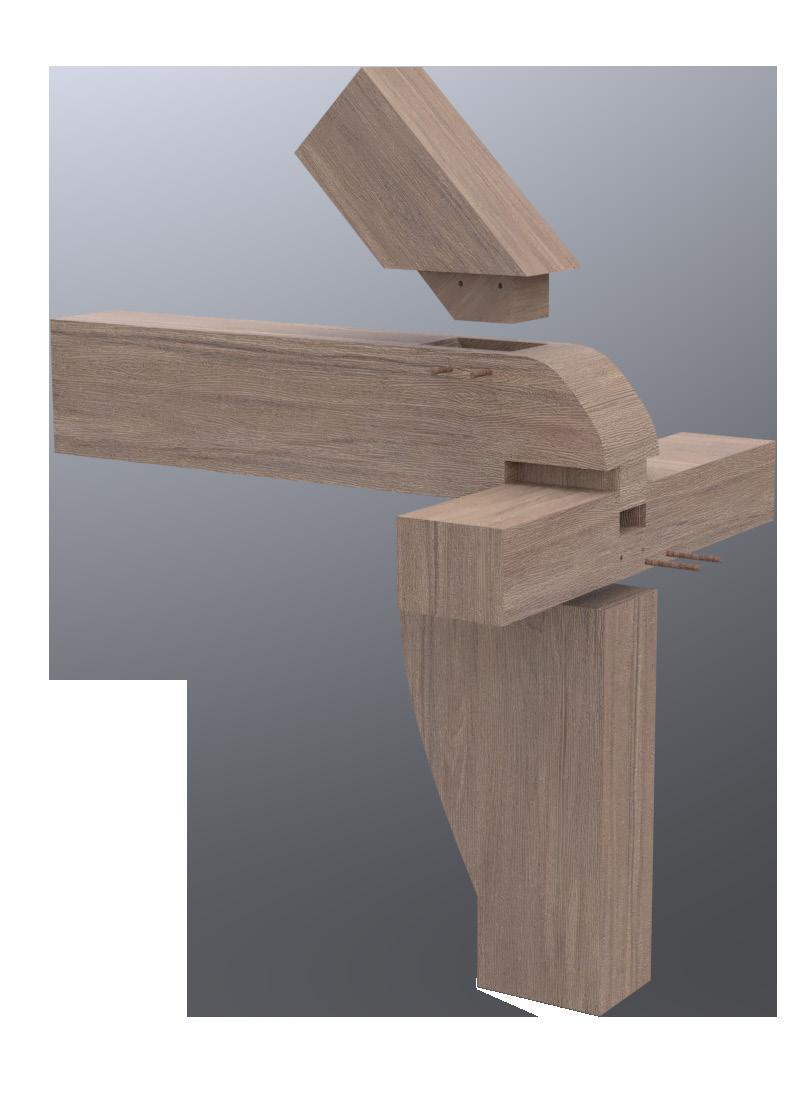
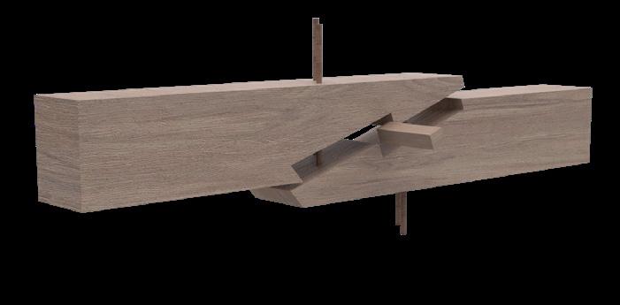
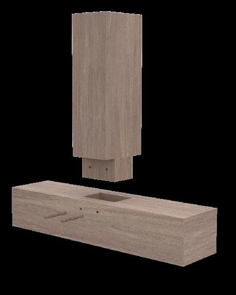
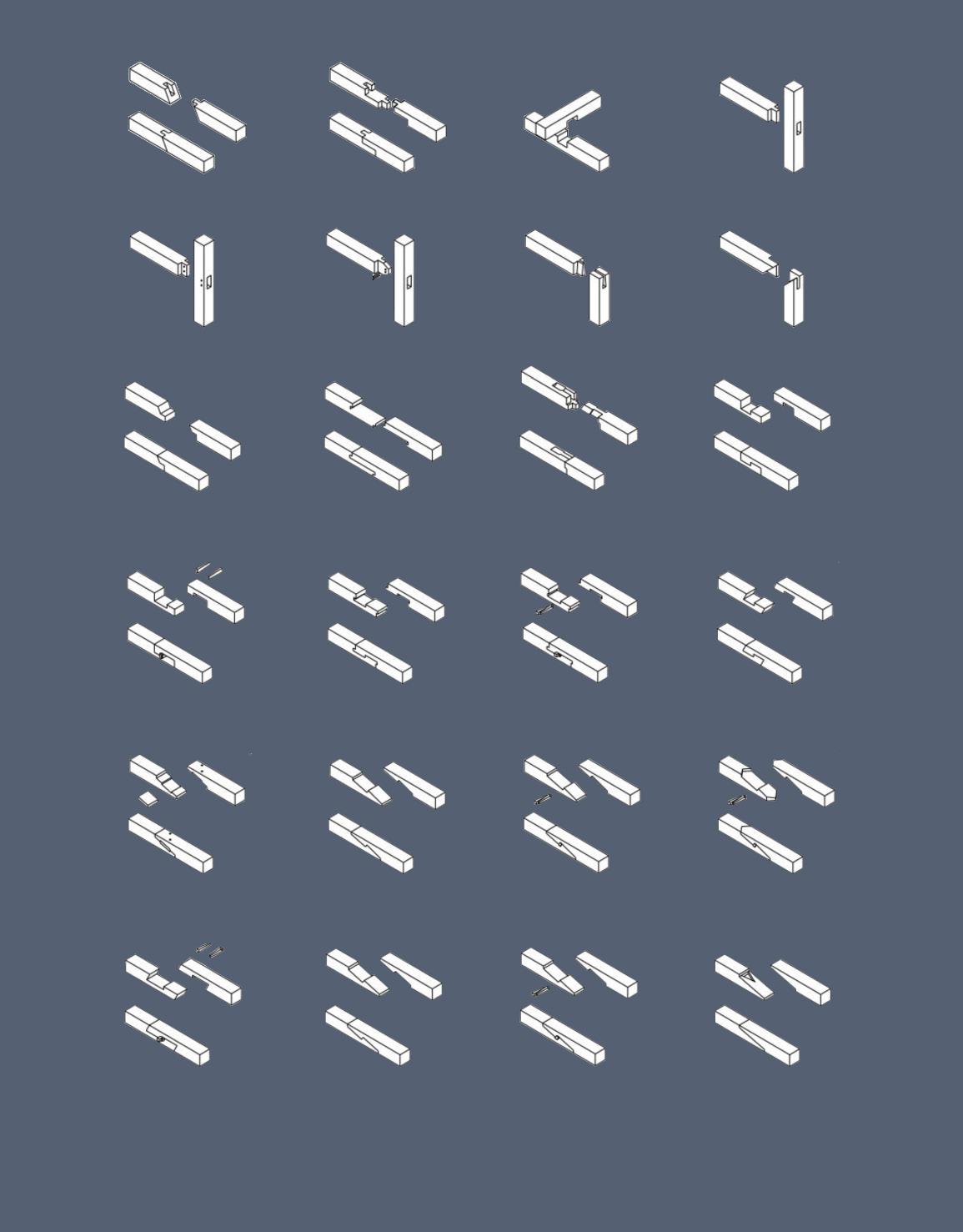
MORTICE AND TENON SCARF JOINT COMPLEX JOINT
cross tiebeam
wall frame
rafter
principal rafter purlins
roof truss
cross tiebeam
wall frame
POST AND TRUSS TYPOLOGY 2
principal rafter purlins cross tiebeam
rafters
AISLED CONSTRUCTION TYPOLOGY 3
TRADITIONAL TIMBER FRAMING ENGLISH VERNACULAR TIMBER ARCHITECTURE
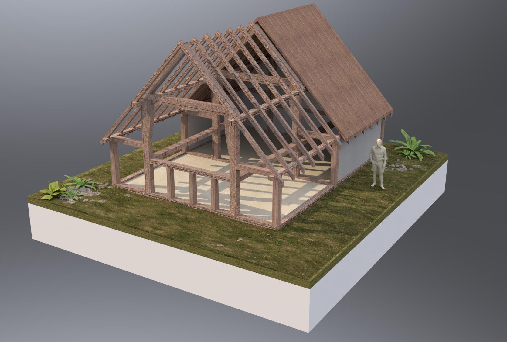
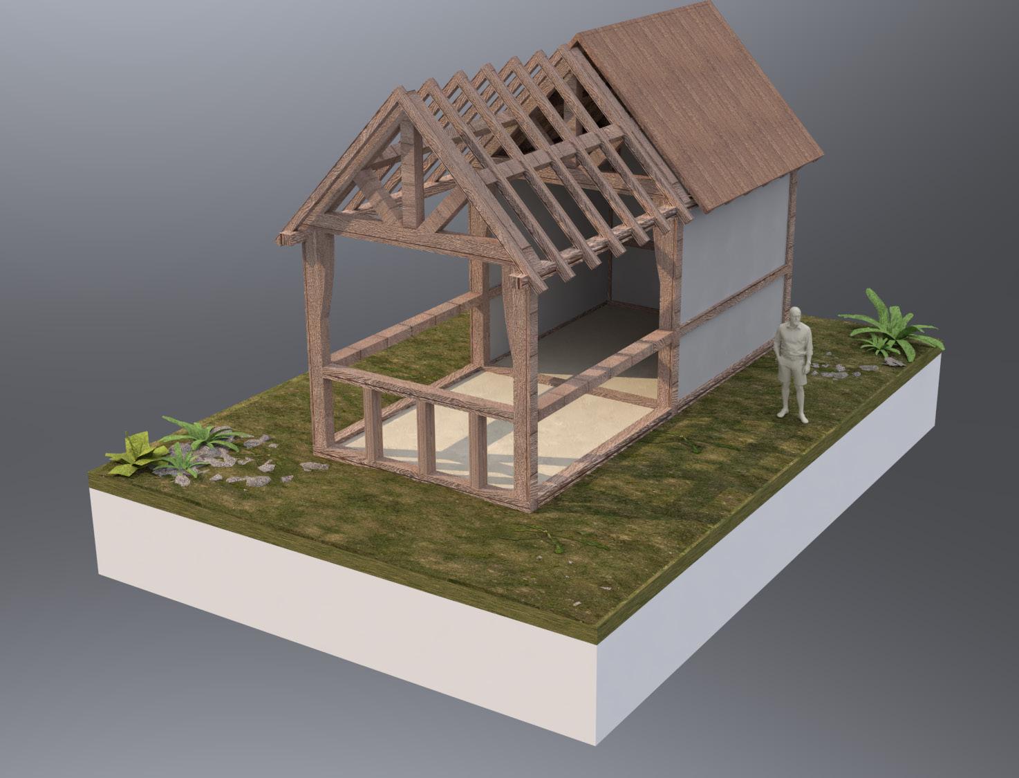
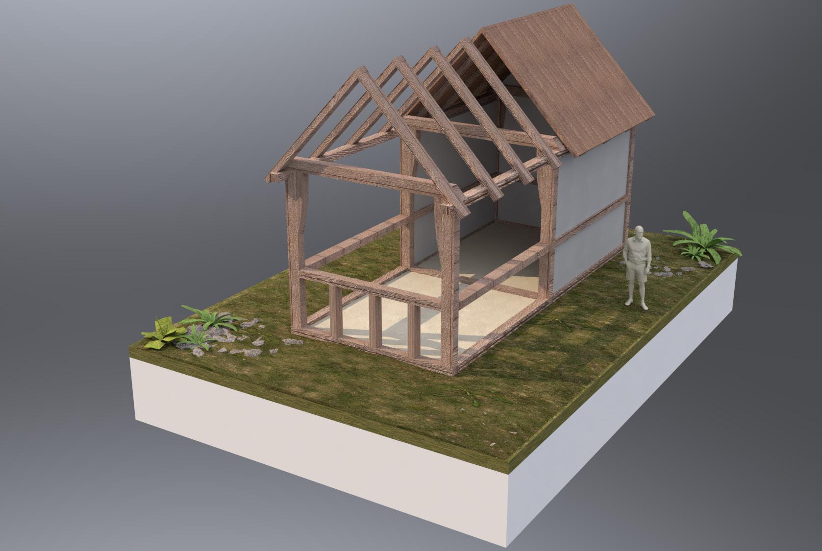
Early studies into the English vernacular timber frame, its typologies and uses
SECTION 1 | EARLY RESEARCH
BOX FRAME TYPOLOGY 1
arcade post 1.01
SECTION 1 | EARLY RESEARCH
1.02
traditional construction.
HARMONDSWORTH GREAT BARN
ENGLISH VERNACULAR TIMBER ARCHITECTURE
HARMONDSWORTH GREAT BARN
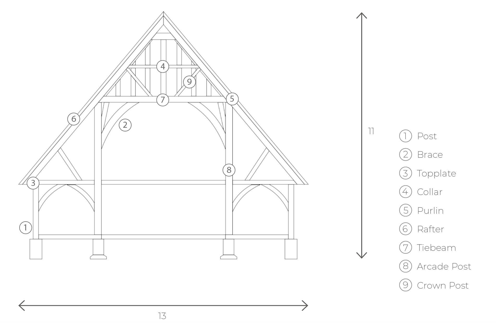
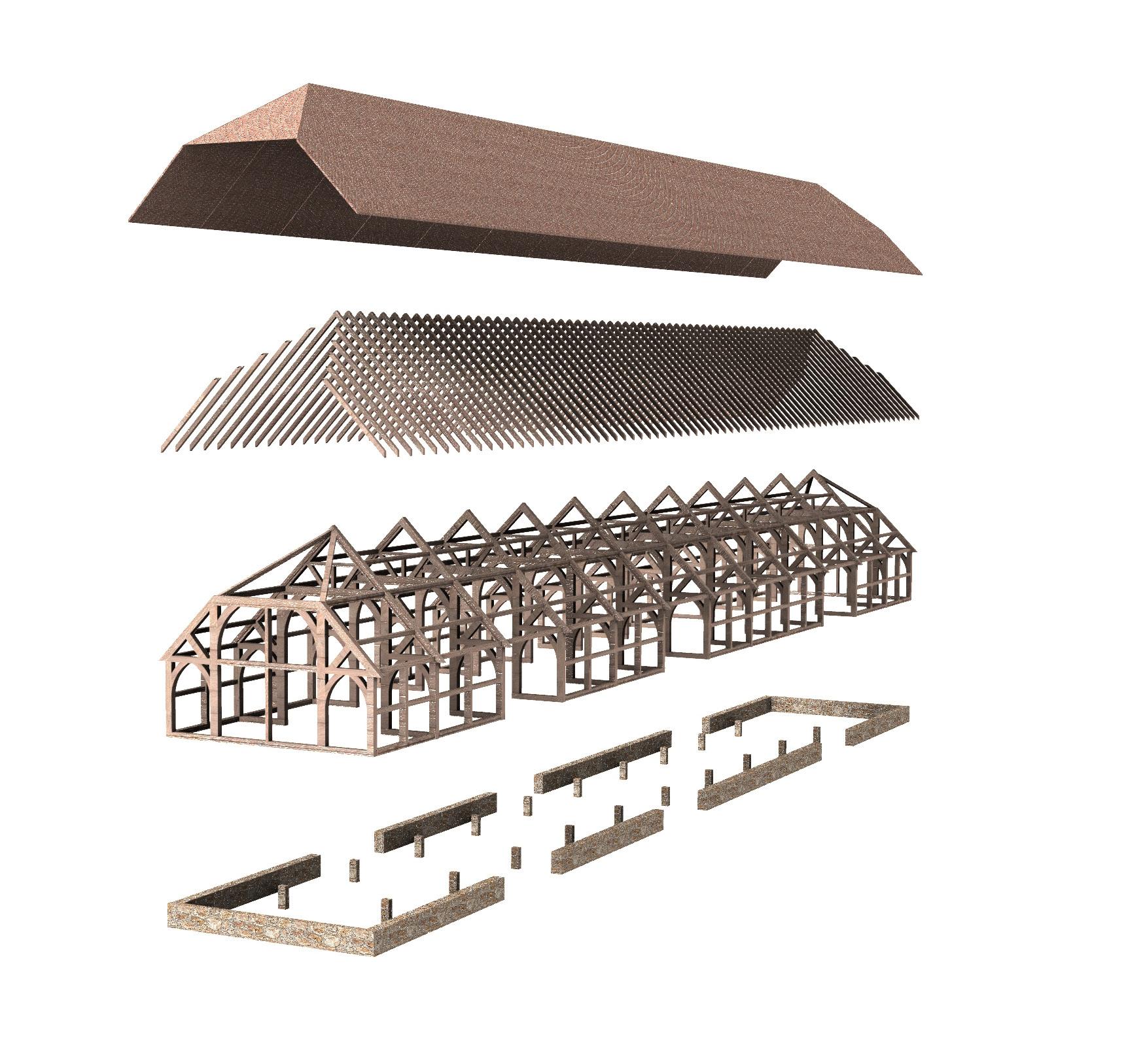
Asield barns are based on a longitudinal frame, with two rows of posts connected by arcade plates. It has numerous internal braces to strengthen the structure. This gives the barn its distinctive internal appearance, with a lattice of beams and braces holding up the roof.

SECTION 1 | EARLY RESEARCH
1.03
TYPICAL AISLED FRAME
AISLED CONSTRUCTION TYPOLOGY

ENGLISH VERNACULAR TIMBER ARCHITECTURE
Harmondsworth Great Barn measures 58m x 13m x 11m. It has an internal volume of 4,900 m3. The barn’s oak arcade posts are 36 cm square, sitting on Reigate sandstone foundation blocks. The timber was cut and fitted together on the ground using scratched assembly marks on the joints to indicate where pieces of timber were to be combined.
SECTION 1 | EARLY RESEARCH
Aisled Construction Timber Frame
Reigate Sandstone Foundation Walls
Common Rafters
Tile & Oak Peg Roof
1.04
HARMONDSWORTH GREAT BARN
SECTION 1 | EARLY RESEARCH
ENGLISH VERNACULAR TIMBER JOINERY HARMONDSWORTH GREAT BARN
1.05
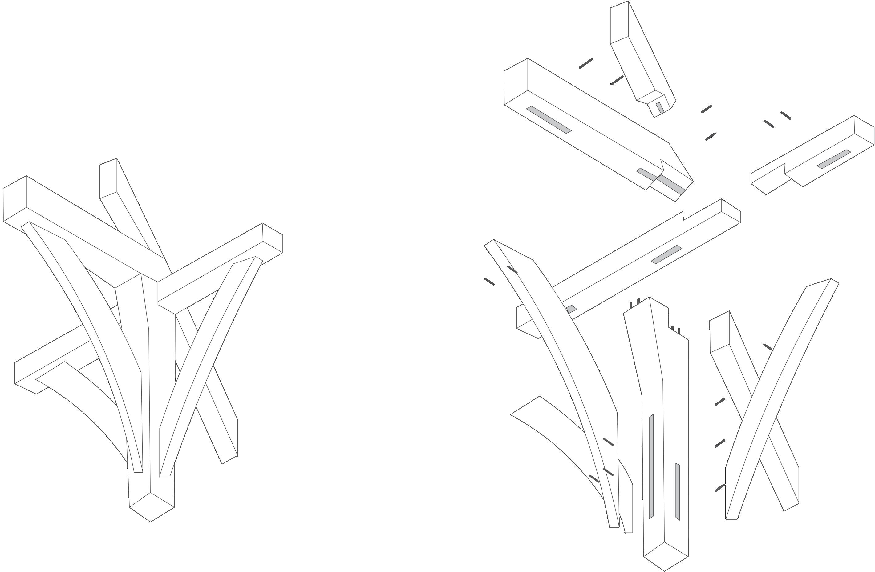
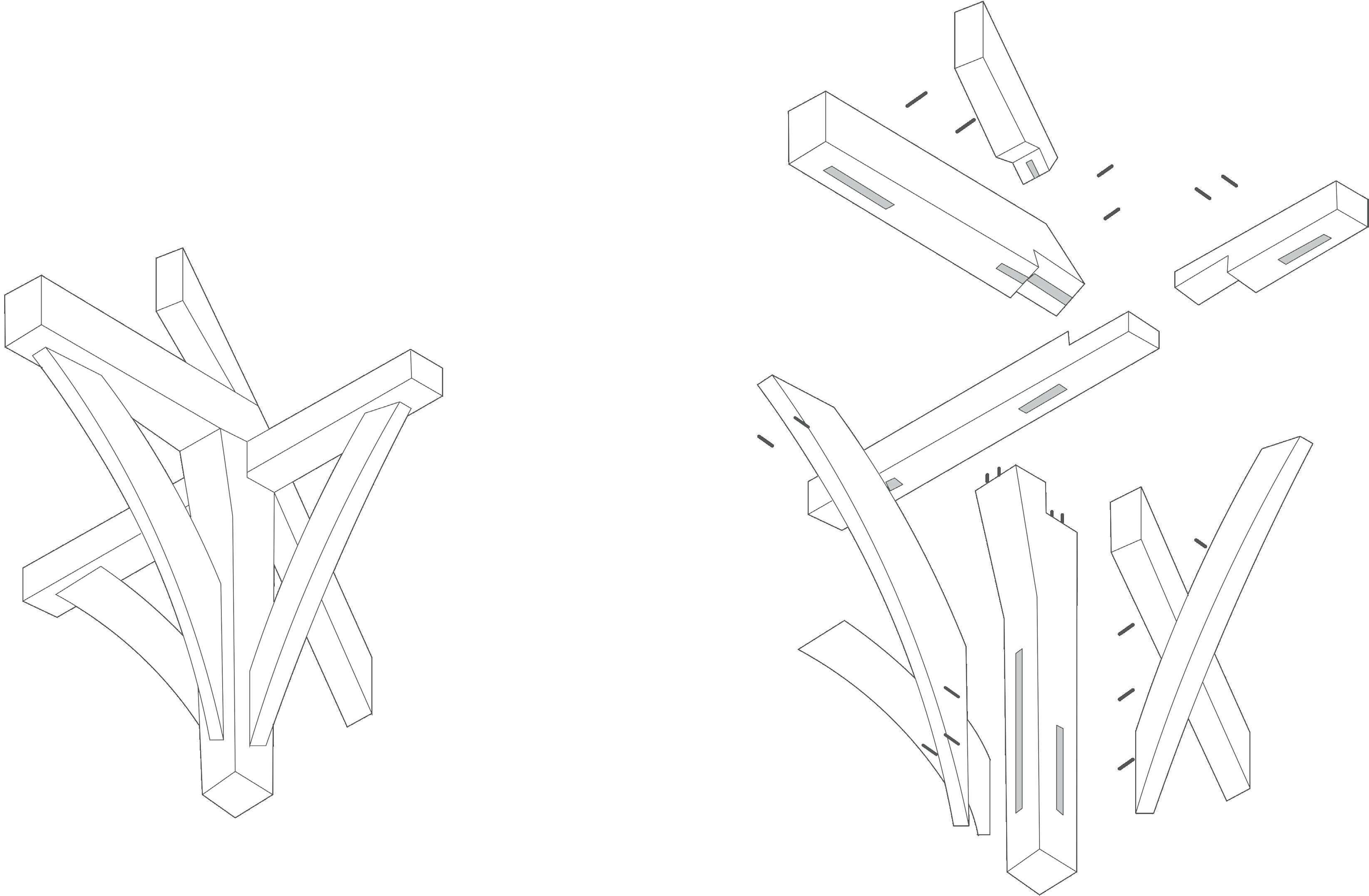
The barn uses complex mortise and tennon joints. Roof purlins run the length of the barn and are tenoned into the principal rafters, with additional support from curved wind braces.
HAMMER-BEAM
ROOF
ENGLISH VERNACULAR TIMBER ARCHITECTURE
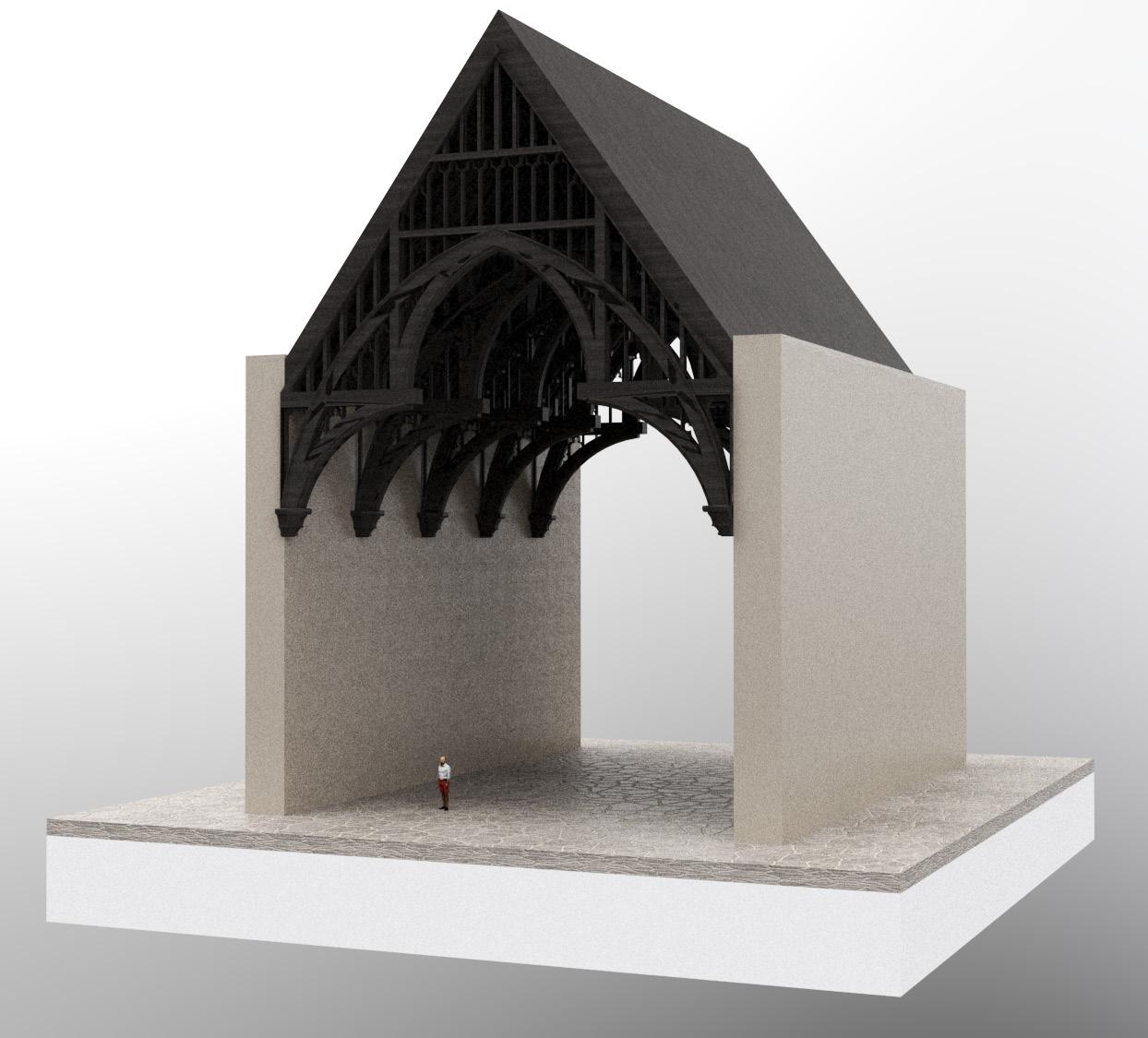
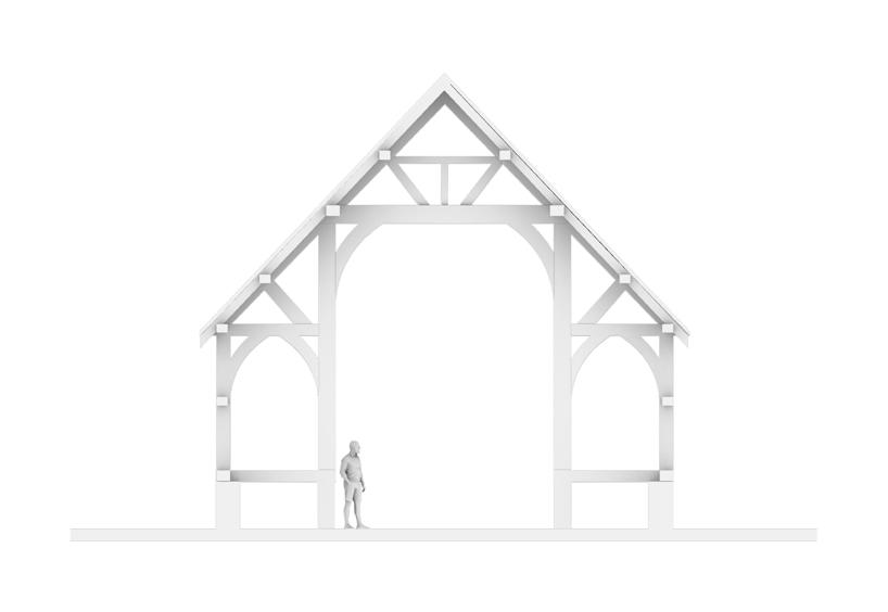
The hammer-beam roof is a decorative, open timber roof truss typical of English Gothic architecture. They are traditionally timber framed, using short beams projecting from the wall on which the rafters land, essentially a tie beam which has the middle cut out. These short beams are called hammer-beams and give this truss its name. The hammer-beam roof of Westminster Hall is the largest medieval timber roof in Northern Europe, measuring 20.7m by 73.2m. The great oak beams serve as horizontal supports fixed to the walls, strengthened by massive buttresses. Wooden arches joined to the top of these beams met centrally in a span of 18 metres.

SECTION 1 | EARLY RESEARCH
WESTMINSTER HALL
1.06
TYPICAL HAMMER-BEAM ROOF

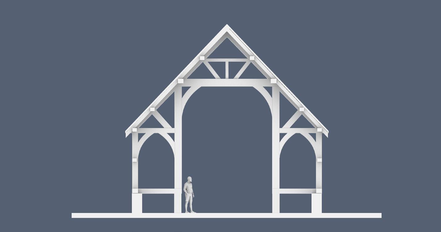

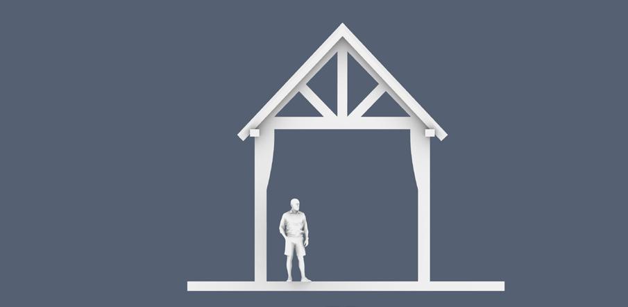
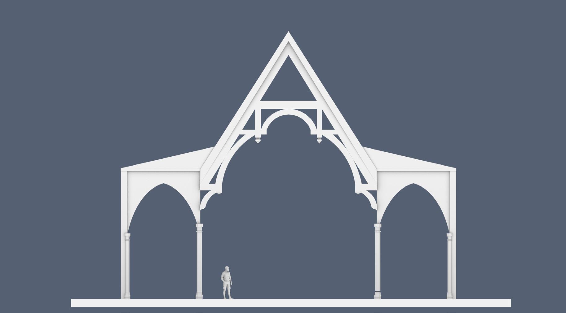
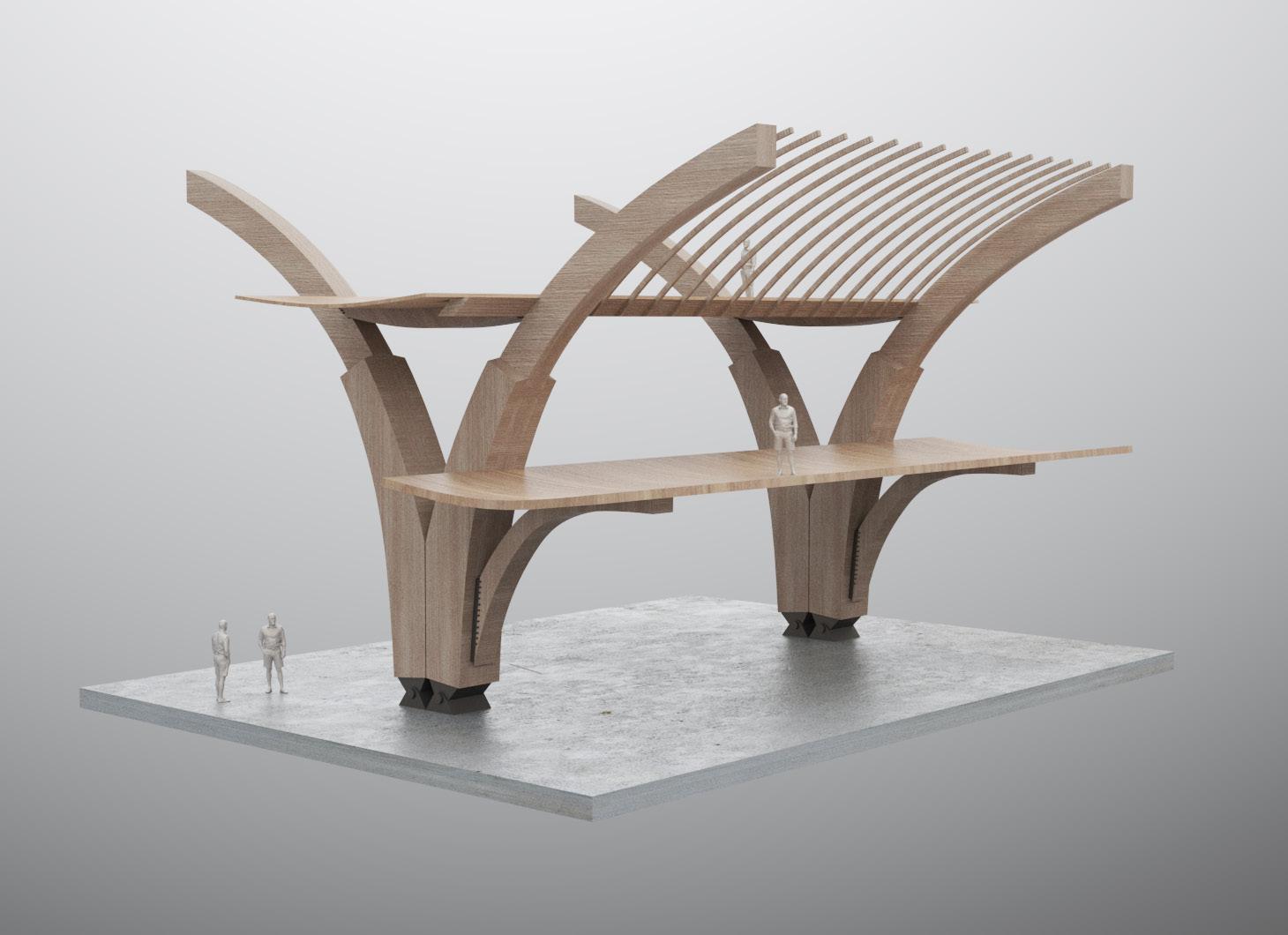
SECTION 1 | EARLY RESEARCH FRAMING TYPOLOGIES STUDY INTO TIMBER FRAME TYPOLOGIES & THE UTILISATION OF THE ROOF 1.07
SECTION 1 | EARLY RESEARCH
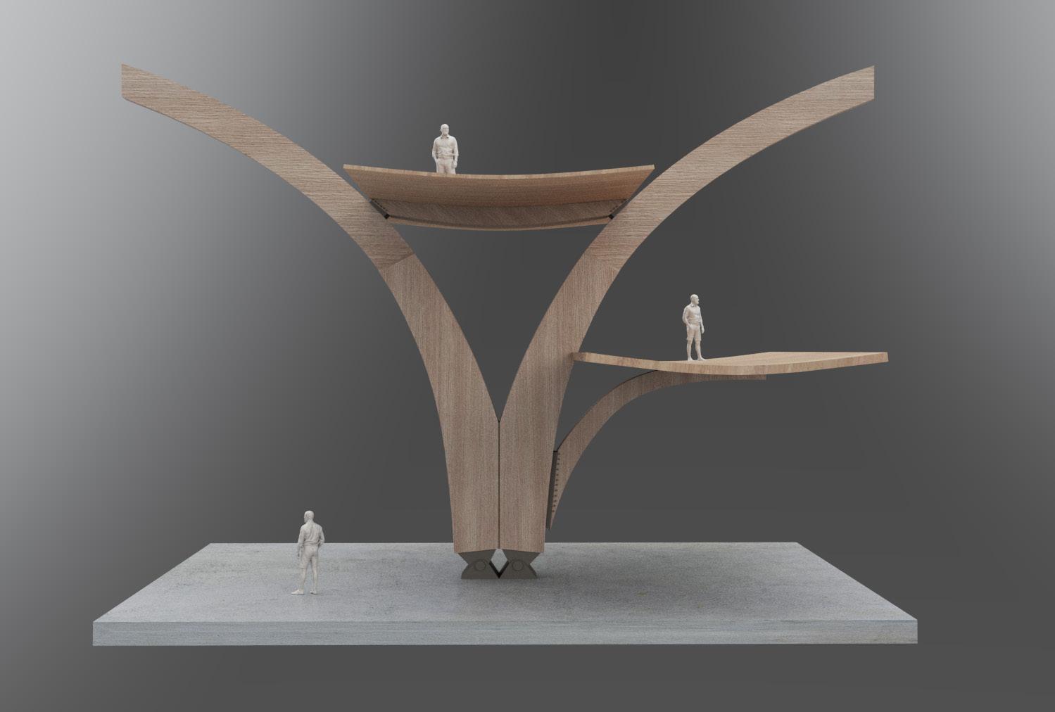
INHABITING THE FRAME
FRAGMENT TESTS UTILISING THE ROOF SPACE OF A TIMBER FRAME
These fragments start to experiment with using aspects of the traditional timber frame to produce more integrated interiors.
1 2 3 1.08
1 Collar / Tiebeam Arch Brace Hammer Brace 2 3
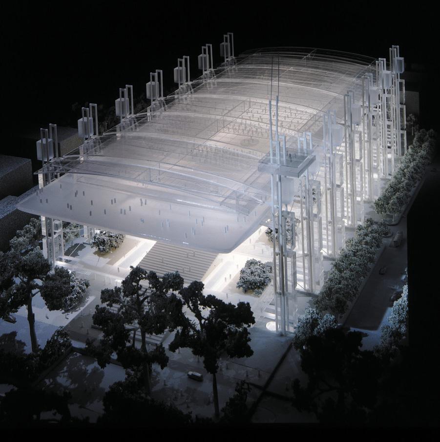

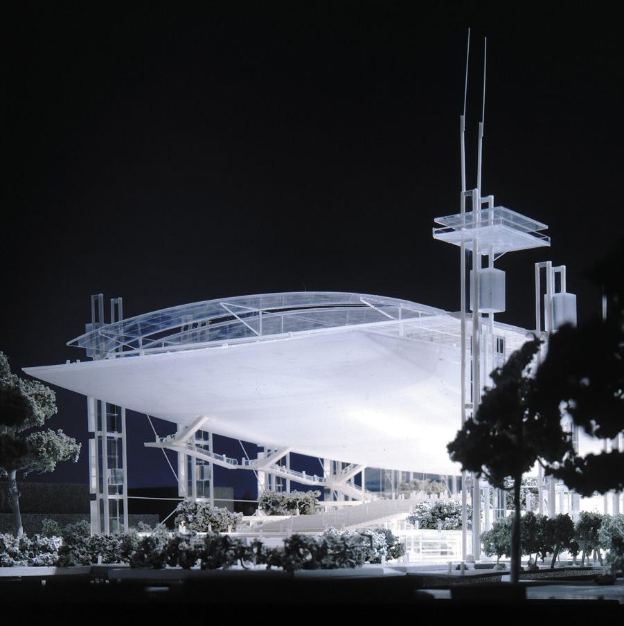


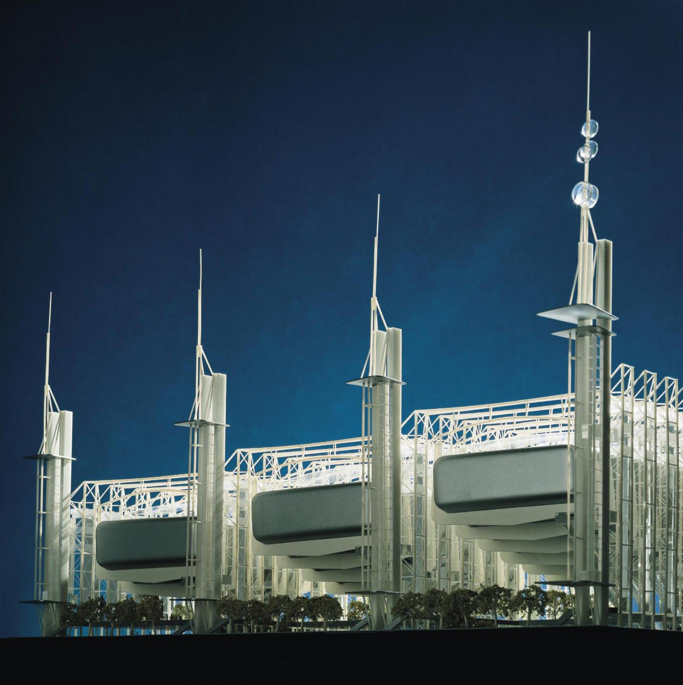
SECTION 1 | EARLY RESEARCH INHABITING THE FRAME FREEING UP THE GROUND PLANE Analysis of precedent projects that are a modern interpretation of inhabiting the frame, and in turn freeing up the ground plane. Both of these schemes by Rogers suspend the building from the frame to create public realm below.
1999
Rome Congress Centre - Rogers Stirk Harbour + Partners
1.09
Tokyo Forum - Rogers Stirk Harbour + Partners 1990
INHABITING THE TIMBER FRAME / FREEING THE GROUND PLANE
FREEING UP THE GROUND PLANE GOING OVER
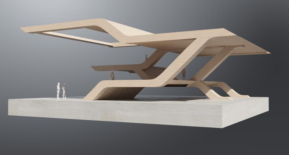
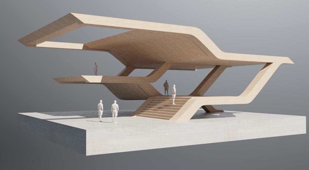
Experimenting with creating variation in the levels and circulation spaces for vertical stratification.
CONNECTING LEVELS
SECTION 1 | EARLY RESEARCH
1.10
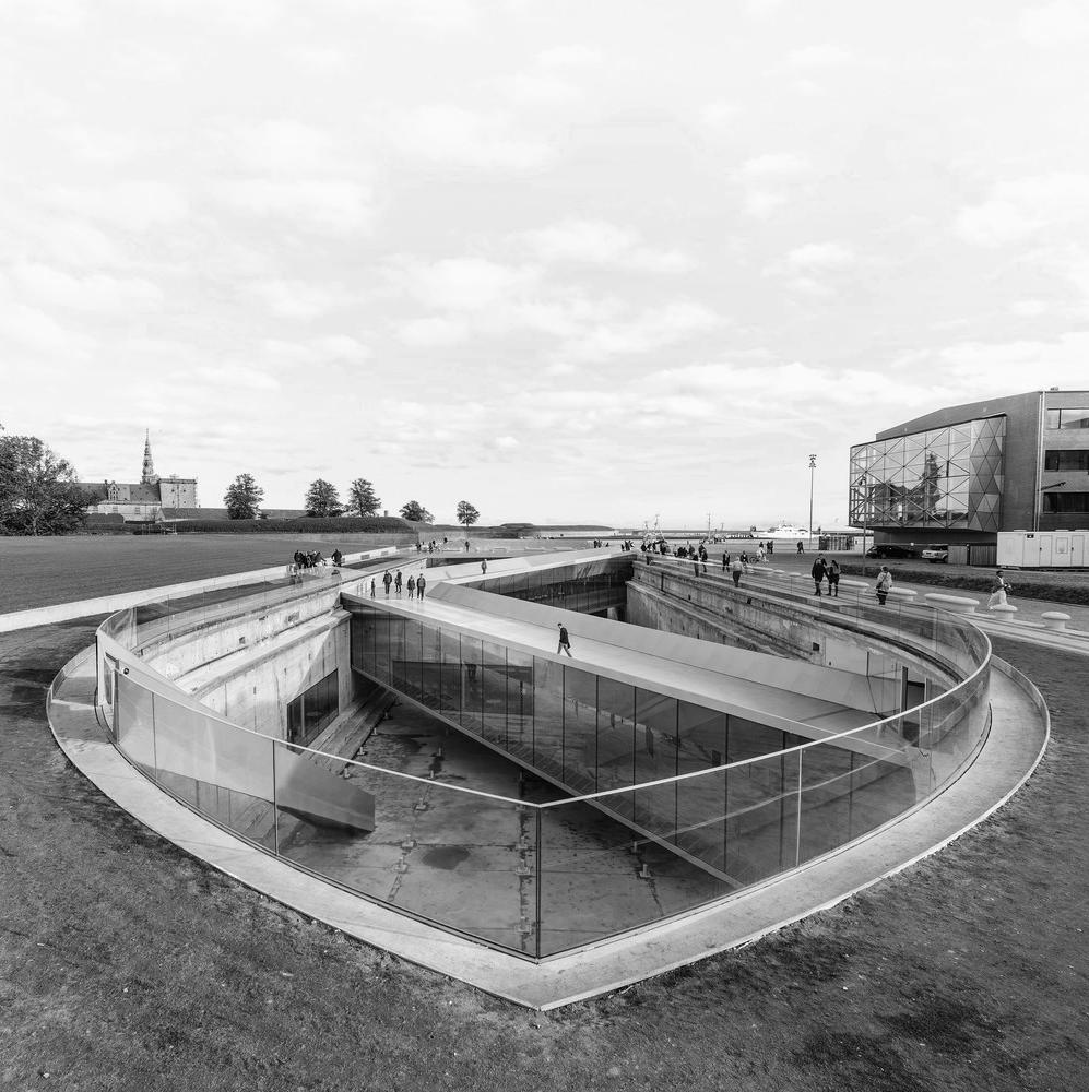
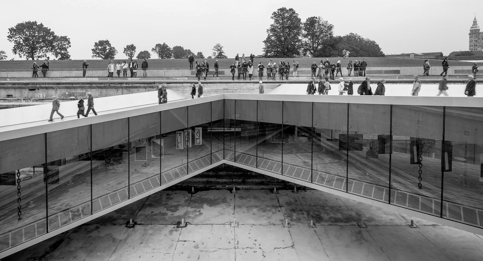
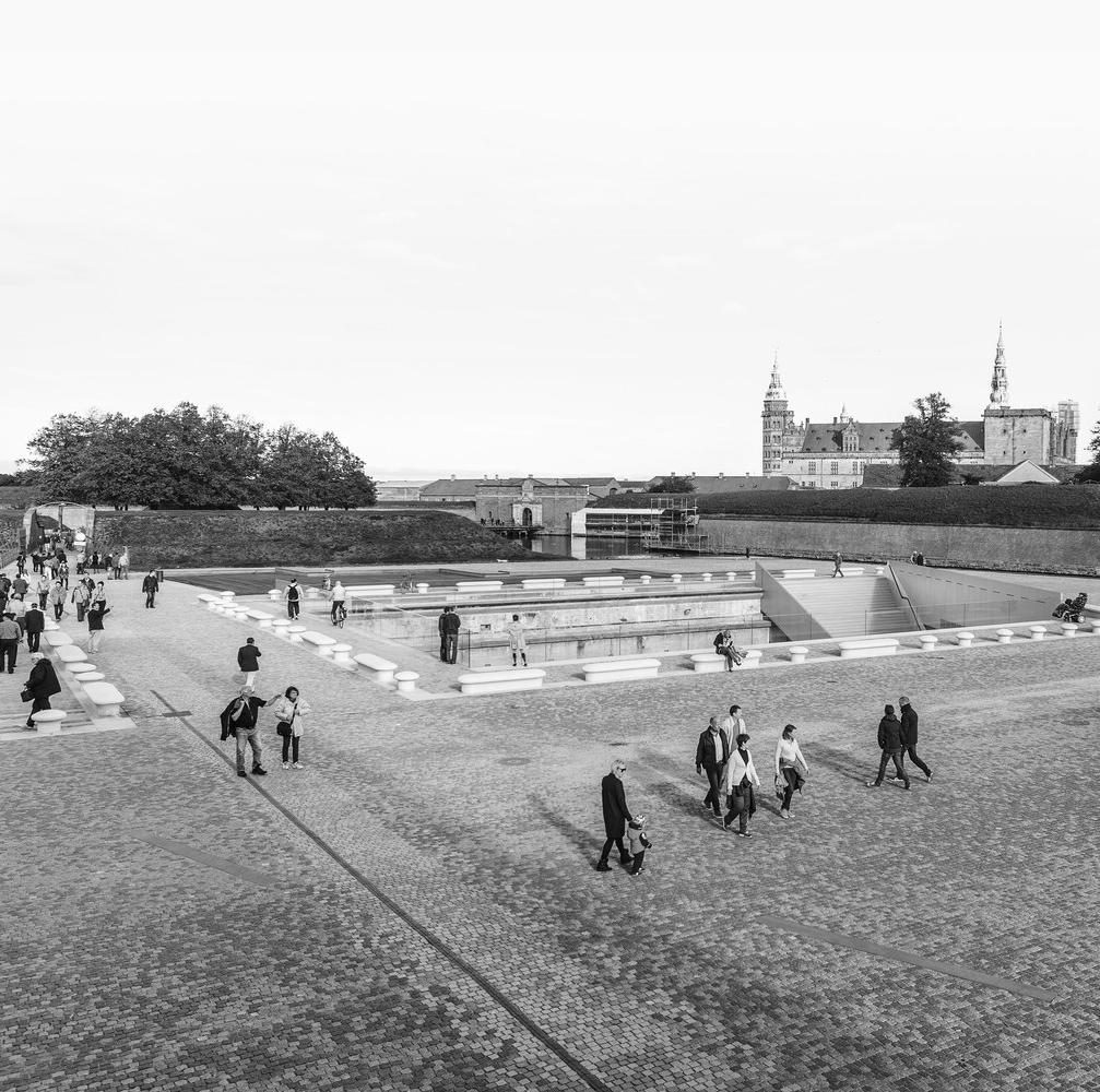
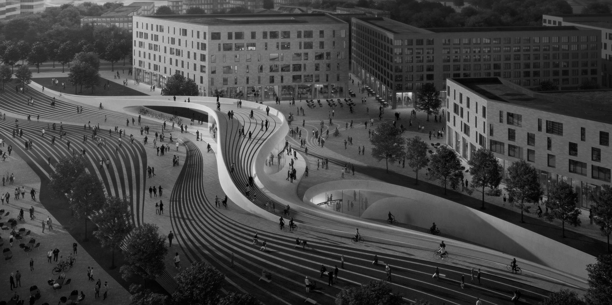
SECTION 1 | EARLY RESEARCH GOING UNDER FREEING UP THE GROUND PLANE An analysis of precedent projects that free up the ground plane by going underground.
of subterranean architecture allow for the space at ground level to be used as public realm, as well as offering unobstructed views over the site.
These examples
Danish National Maritime Museum - Bjarke Ingels Group 2013
1.11
Fornebubanen Metro Line - Zaha Hadid Architects 2018
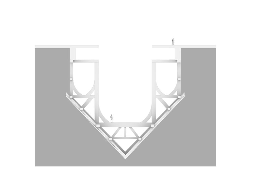
SUBTERRANEAN FORM
GOING UNDER
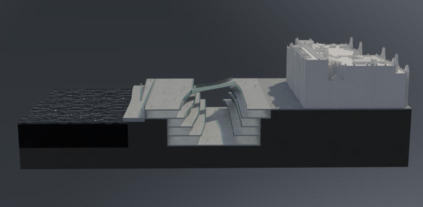
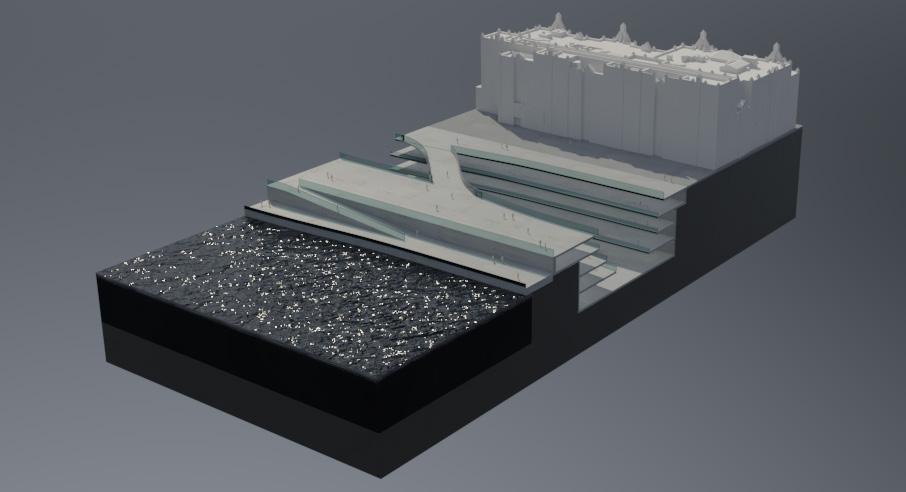
Experimenting with ‘going under’, creating subterranean architecture to free up the ground plane on the surface level.
SECTION 1 | EARLY RESEARCH
1.12
REVERSAL - INHABITING THE FRAME / FREE THE GROUND PLANE BY GOING UNDER
SECTION 2: CONTEXT AND BRIEF 02



SECTION 2 | CONTEXT & BRIEF
BRIEF PROPOSAL 2.01
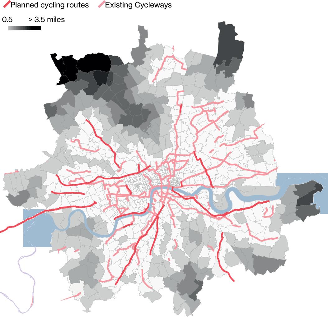
CYCLING IN LONDON
an o er intresting solutions. Utilising the space above London’s existing rail infrastructure could help elivate the pressure on the road. SkyCycle proposes a network of around the city. It would also o er cyclists a much safer, quicker and more pleasent route around the city.


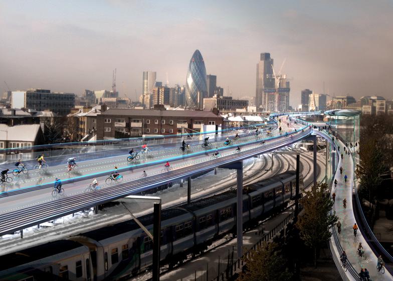
Another possibility of using existing infrastructure is underground. Multiple run under London, connecting key points in the city. The proposal is to refurbish these tunnels to become cycle routes.
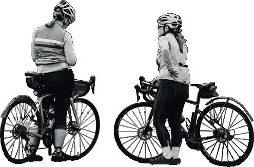
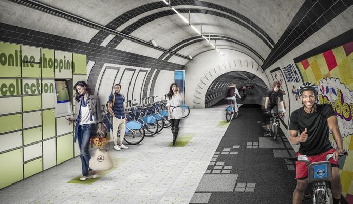
Combining these two ideas to create a around the city, as well as new stations/connection points, could be the


SECTION 2 | CONTEXT & BRIEF
2.02
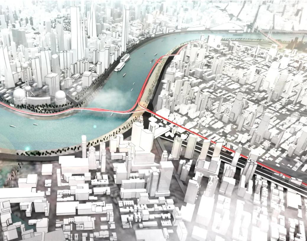
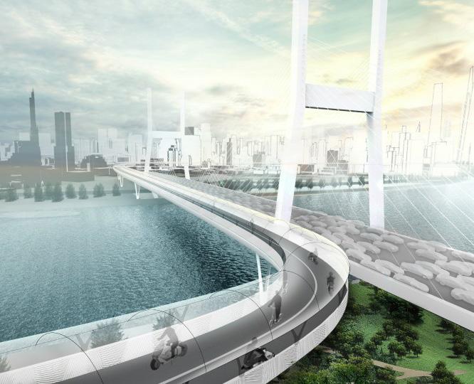
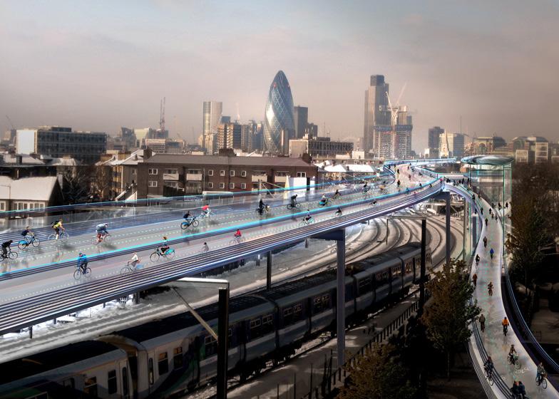
ELEVATED CYCLING NETWORK
PRECEDENT PROJECTS
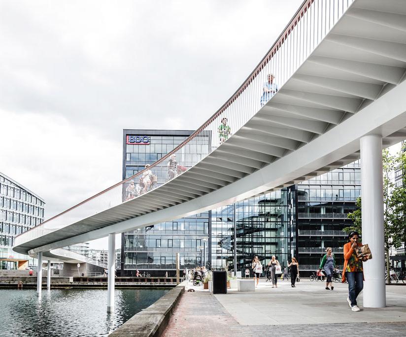
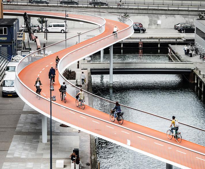
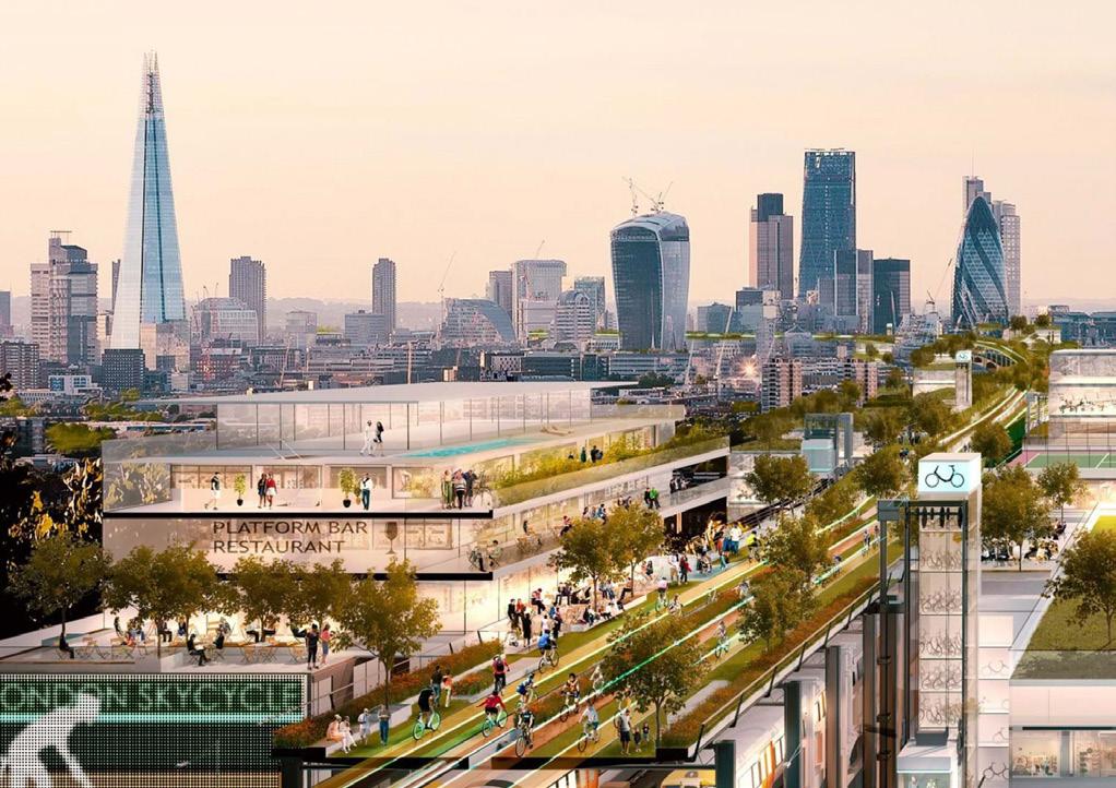
Existing schemes and proposals for an elevated cycling network in an urban environment. Currently the Cykelslangen in Copenhagen is the only fully realised proposal.
SECTION 2 | CONTEXT & BRIEF
SkyCycle - Fosters + Partners 2013
BMW Vision E³ Way - BMW Group 2017
2.03
Cykelslangen - Dissing + Weitling 2014
SUBTERRANEAN CYCLING NETWORK PRECEDENT PROJECTS

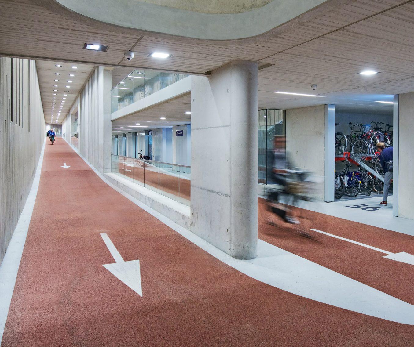
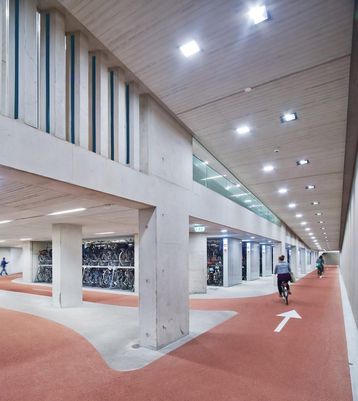

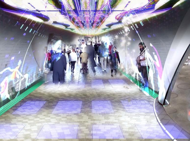
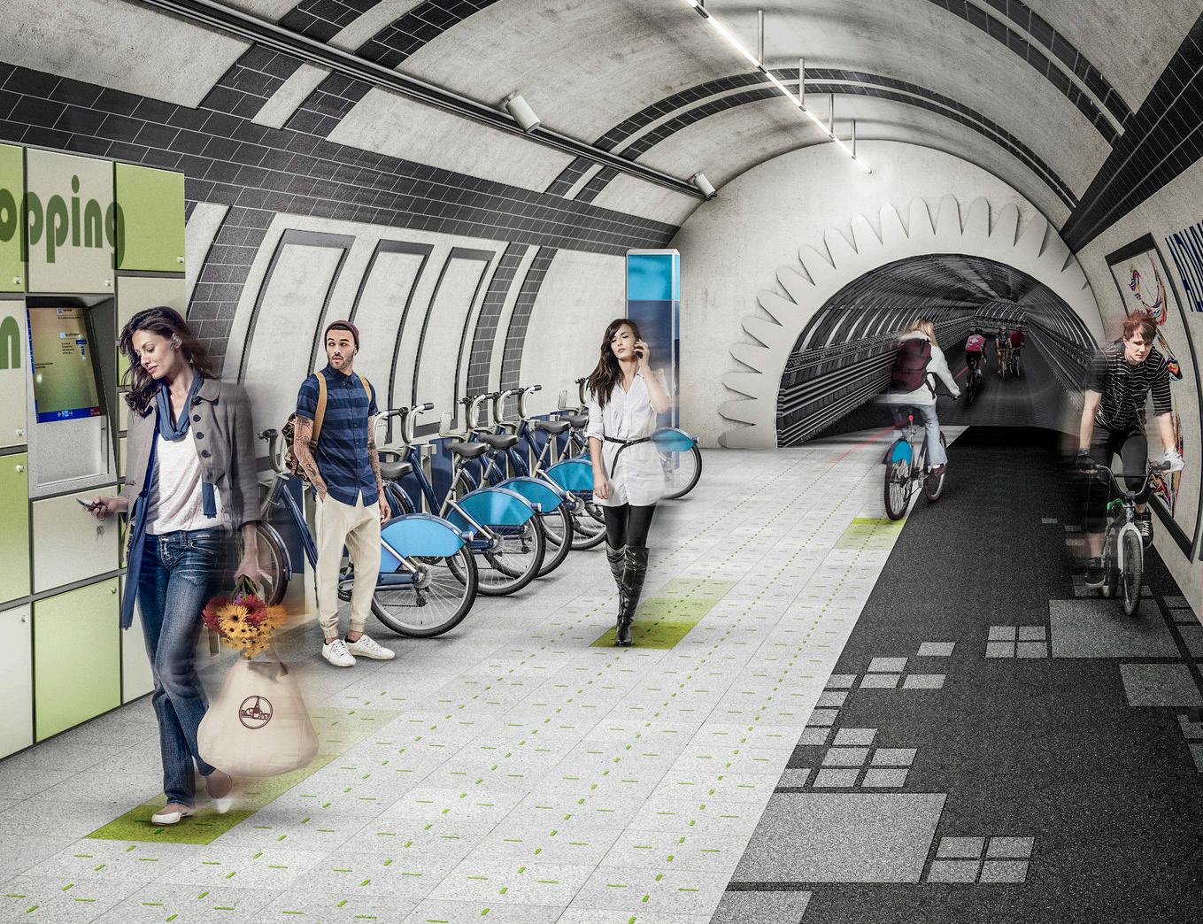
SECTION 2 | CONTEXT & BRIEF
London Underline - Gensler 2015
Existing schemes and proposals for an elevated cycling network in an urban environment. Currently the Cykelslangen in Copenhagen is the only fully realised proposal.
2.04
Utrecht Central Station Bike Park - Ector Hoogstad Architecten 2011
INTERFACE WITH THE THAMES
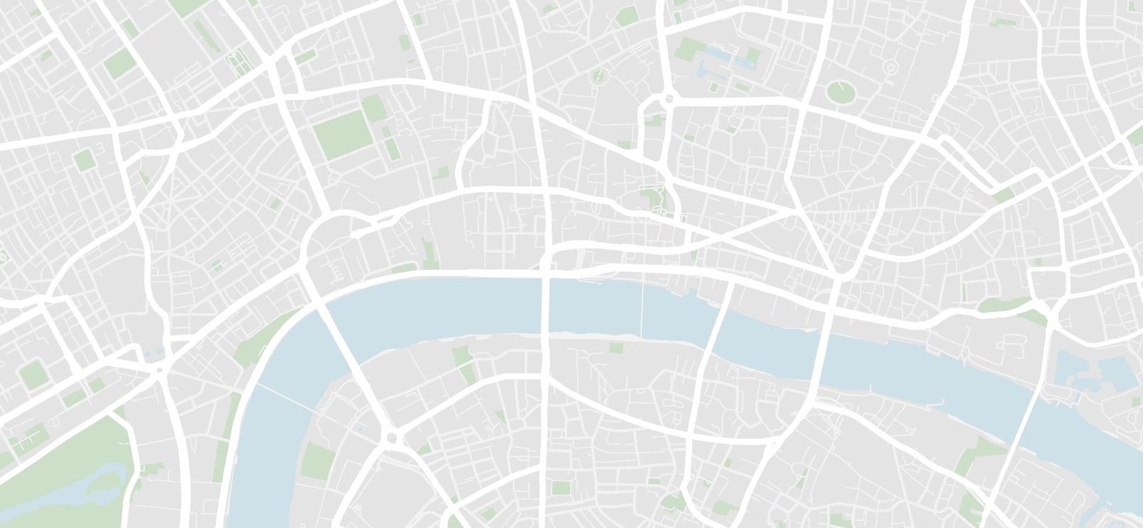
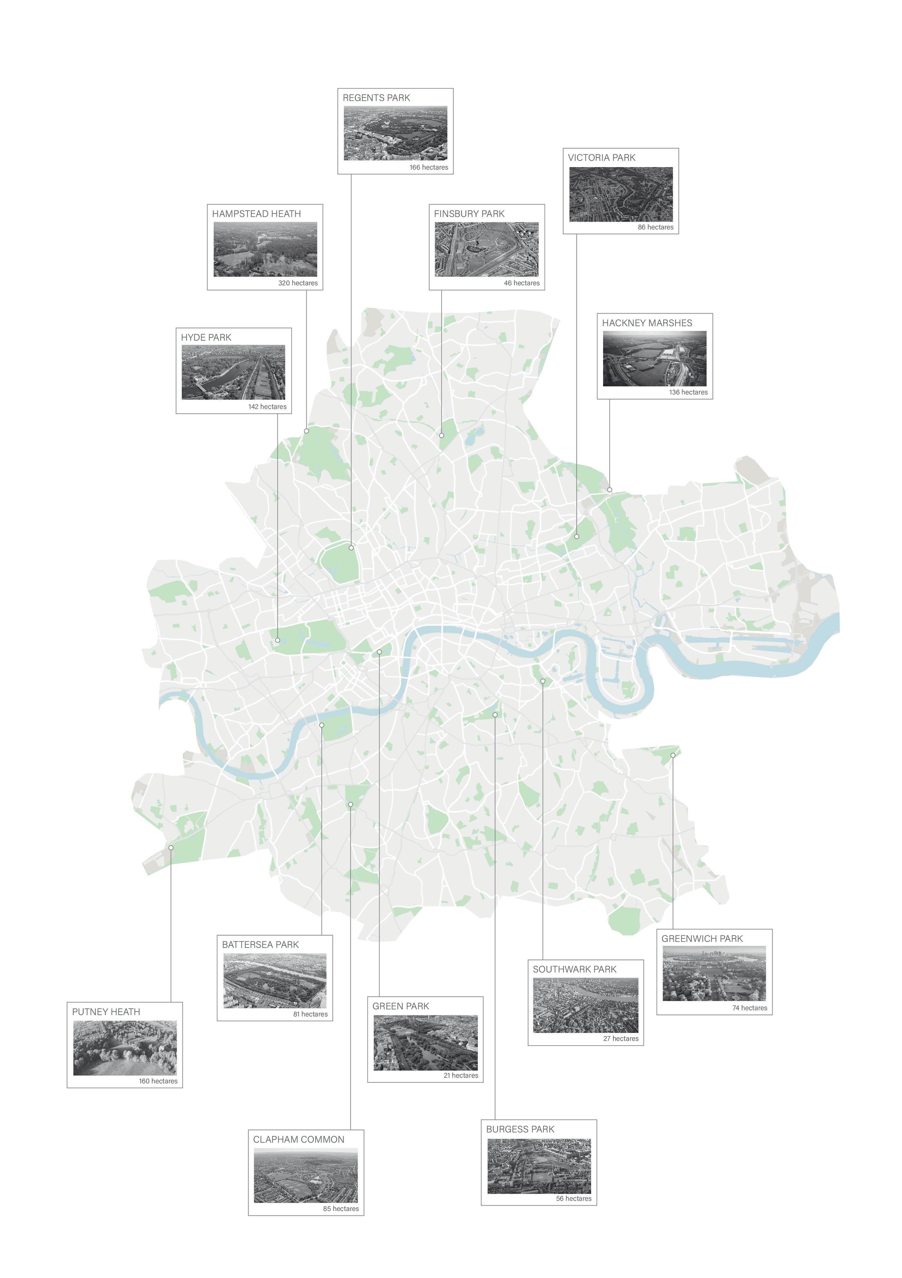
The area along the river within central London lacks open public green space. The Northern bank of the river is occupied predominantly with the main road and doesn’t allow citizens to engage with the city and the river. New public spaces along the interface with the Thames could bring much needed open public space to the city center.
MAPPING PUBLIC GREEN SPACE WITHIN CENTRAL LONDON:

SECTION 2 | CONTEXT & BRIEF
plane in urban areas can help to increase the number of public outdoor spaces in city centers.
2.05
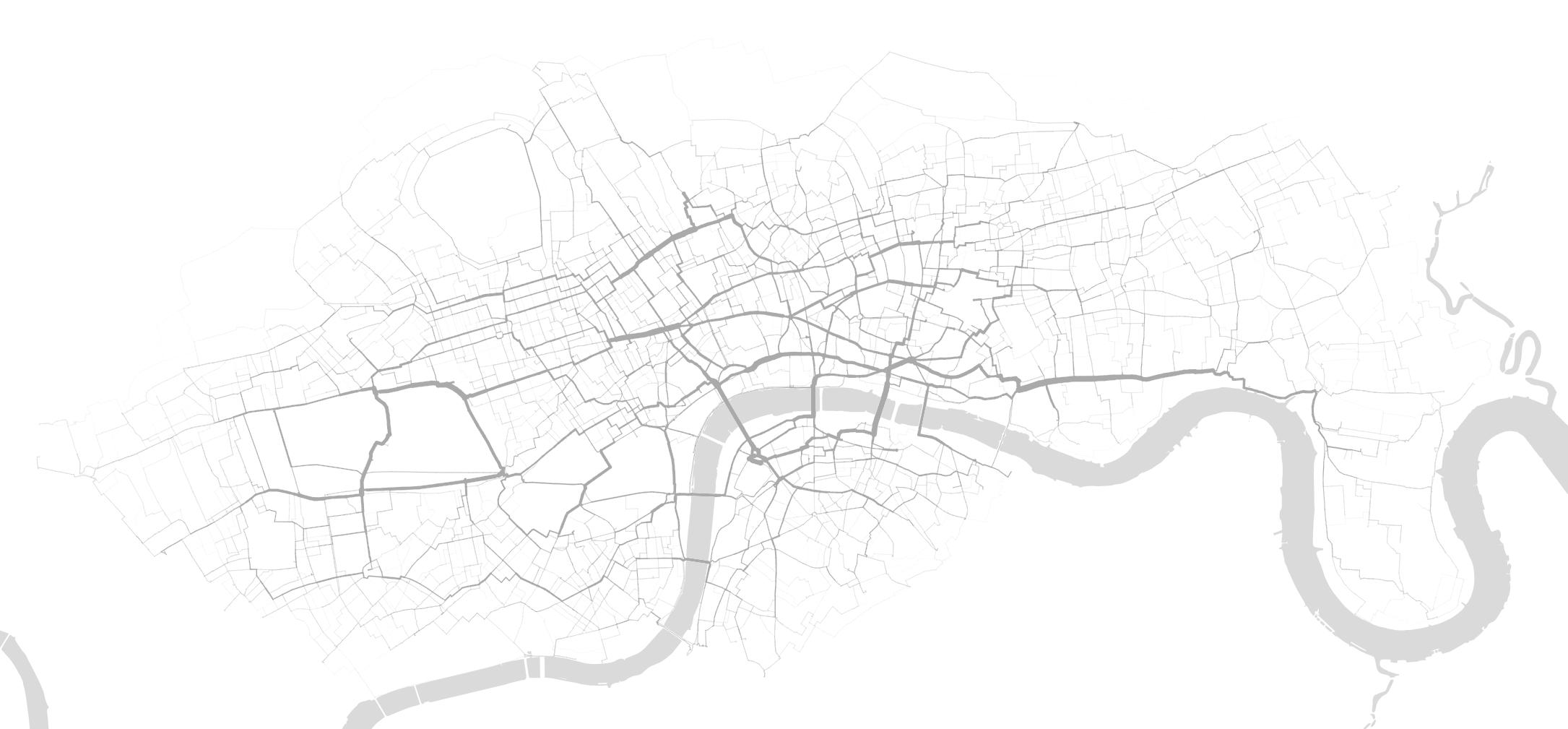
BARCLAYS CYCLE HIRE
Frequent Routes & Volume
STRAVA POPULAR ROUTES MAP
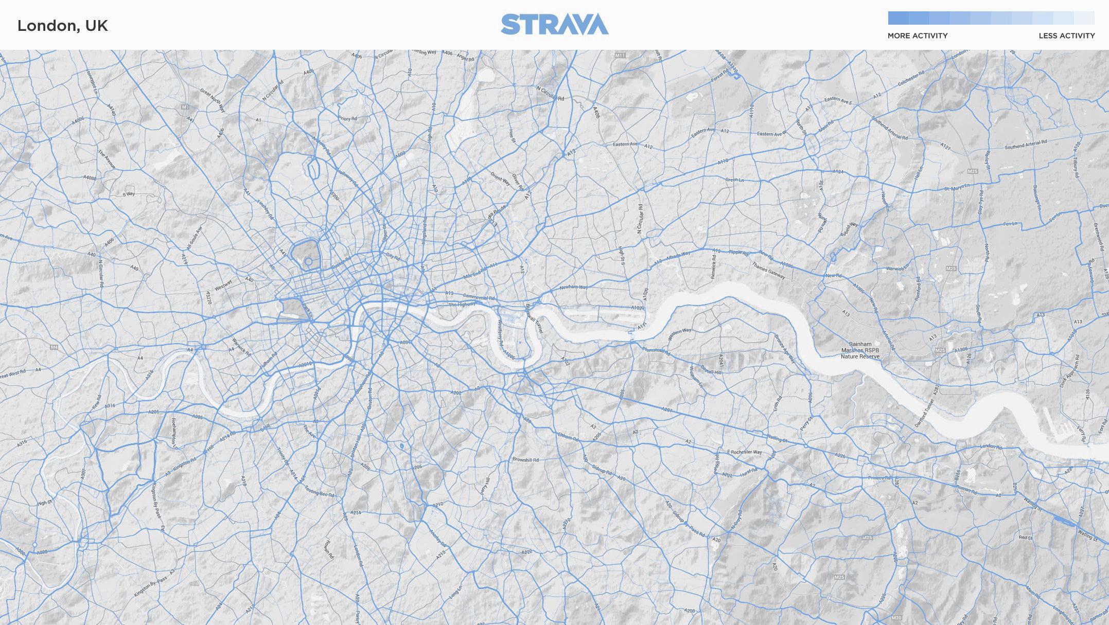

Darker lines indicate more popular routes
SECTION 2 | CONTEXT & BRIEF
more
less activity 2.06
activity
EXISTING INFRASTRUCTURE ESTABLISHING EXISTING CYCLING CONNECTION POSSIBILITIES
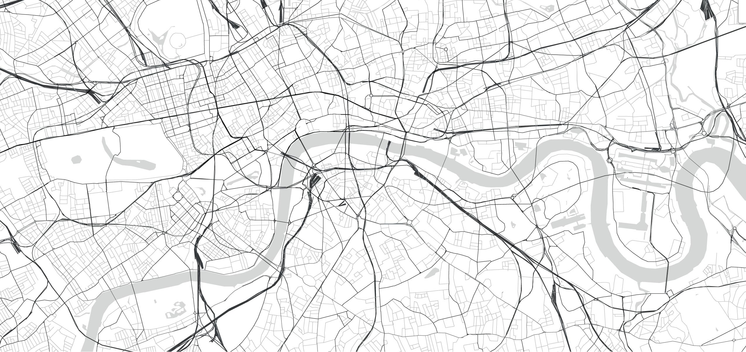

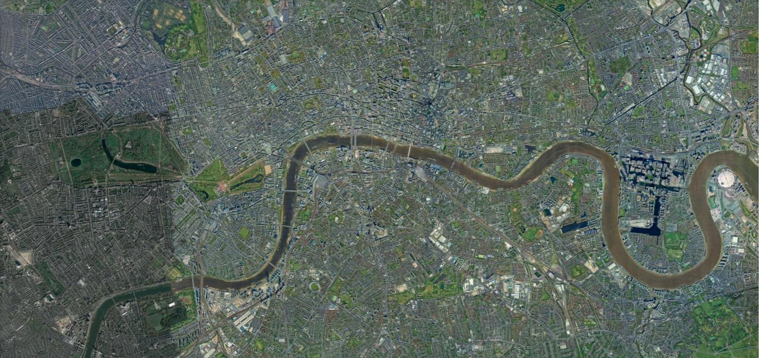
The proposal includes turning London’s disused underground spaces into a network of cycle paths, as well as building a network of elevated platforms along existing rail lines. For example using the branch of the Piccadilly Line that runs from Holborn to Temple, and the line that connects Green Park to Charing Cross. The High Line would be constructed above existing suburban rail lines to create new cycle routes throughout the capital. Identifying the possible routes to connect London by bike. These lines would then connect at existing and new stations around the city.

SECTION 2 | CONTEXT & BRIEF
2,000m HIGHLINE HIGHLINE NODE 2,000m
2.07
UNDERLINE UNDERLINE NODE


SECTION 2 | CONTEXT & BRIEF PROGRAMME NEW CYCLING NETWORK HUB
2.08
The hub proposes a central meeting point for the High Line and Under Line cycle networks in London. It will include bike storage, repair shops, changing facilities and lockers, as well as cafés and retail outlets. The scheme will also include a new green space for London, the Embankment Gardens.
CYCLE LINE
Cycle Line consists of two branches; the High Line and the Under Line. A central interchange in the city is required to seamlessly move cyclists from one mode of transport to another. This central hub not only serves as an interchange from an elevated network to a subterranean network, but also to the ground level and the city beyond.
The aim is to provide a safe and pleasant route through the city by bicycle, to deal with the post pandemic cycling boom, but also to encourage others to chose a more sustainable mode of transport.
COMPONENTS CYCLE LINE
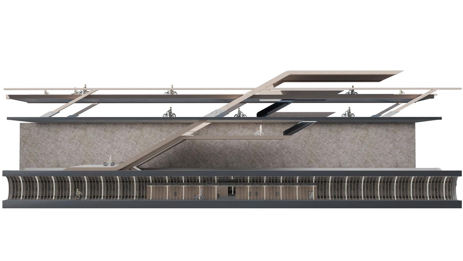
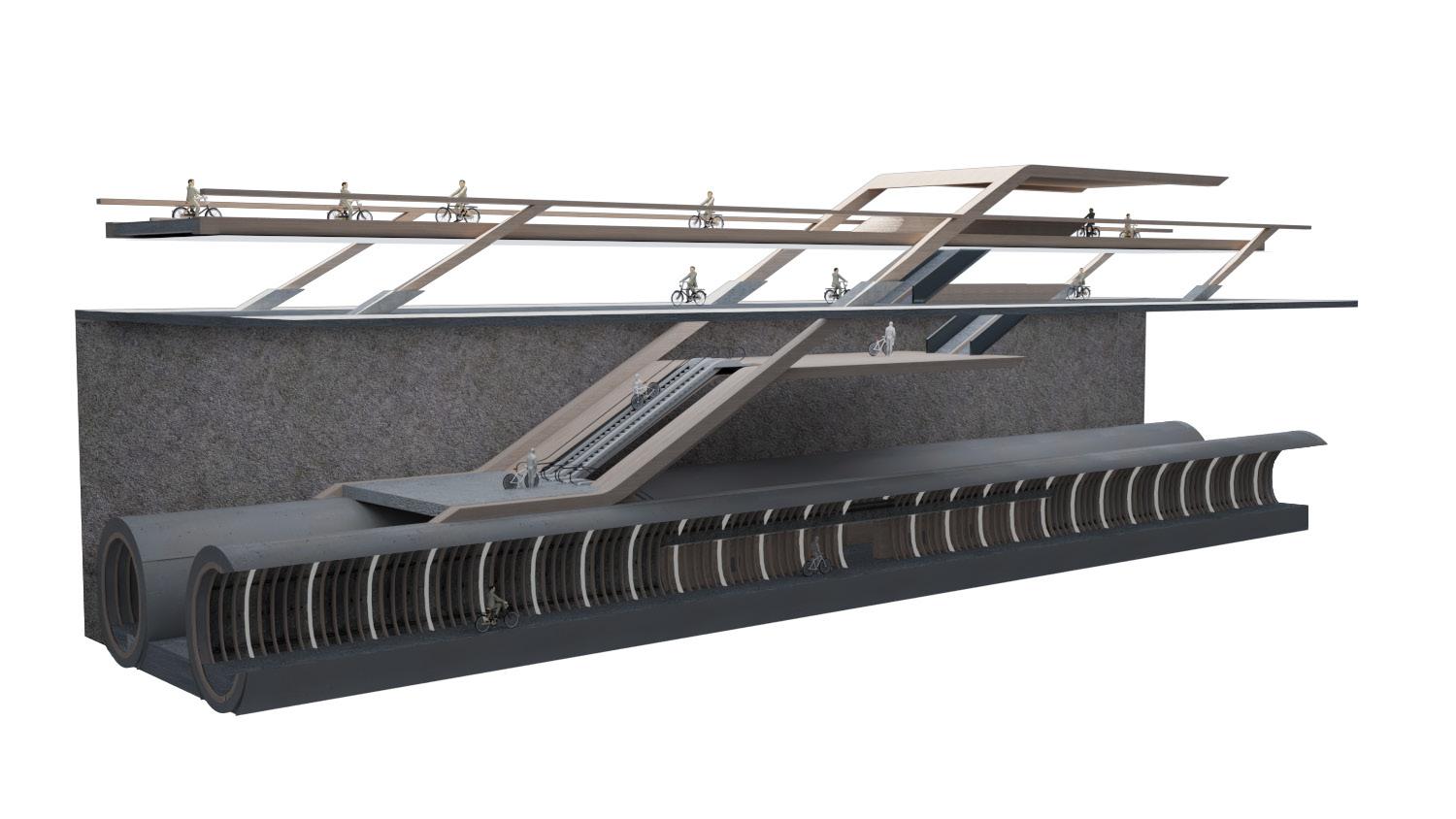
The scheme involves a new cycling network for London, the Cycle Line. Cycle Line includes the High Line, a series of elevated bike paths, and the Under Line, a network of cycling tunnels underground. These two components interchange at carefully positioned connection points around the city.
SECTION 2 | CONTEXT & BRIEF
An initial fragment test experimenting with connecting the High Line with the Under Line and the ground plane
INTERCHANGE
2.09


ESTABLISHING SITE BOUNDARIES
2.10
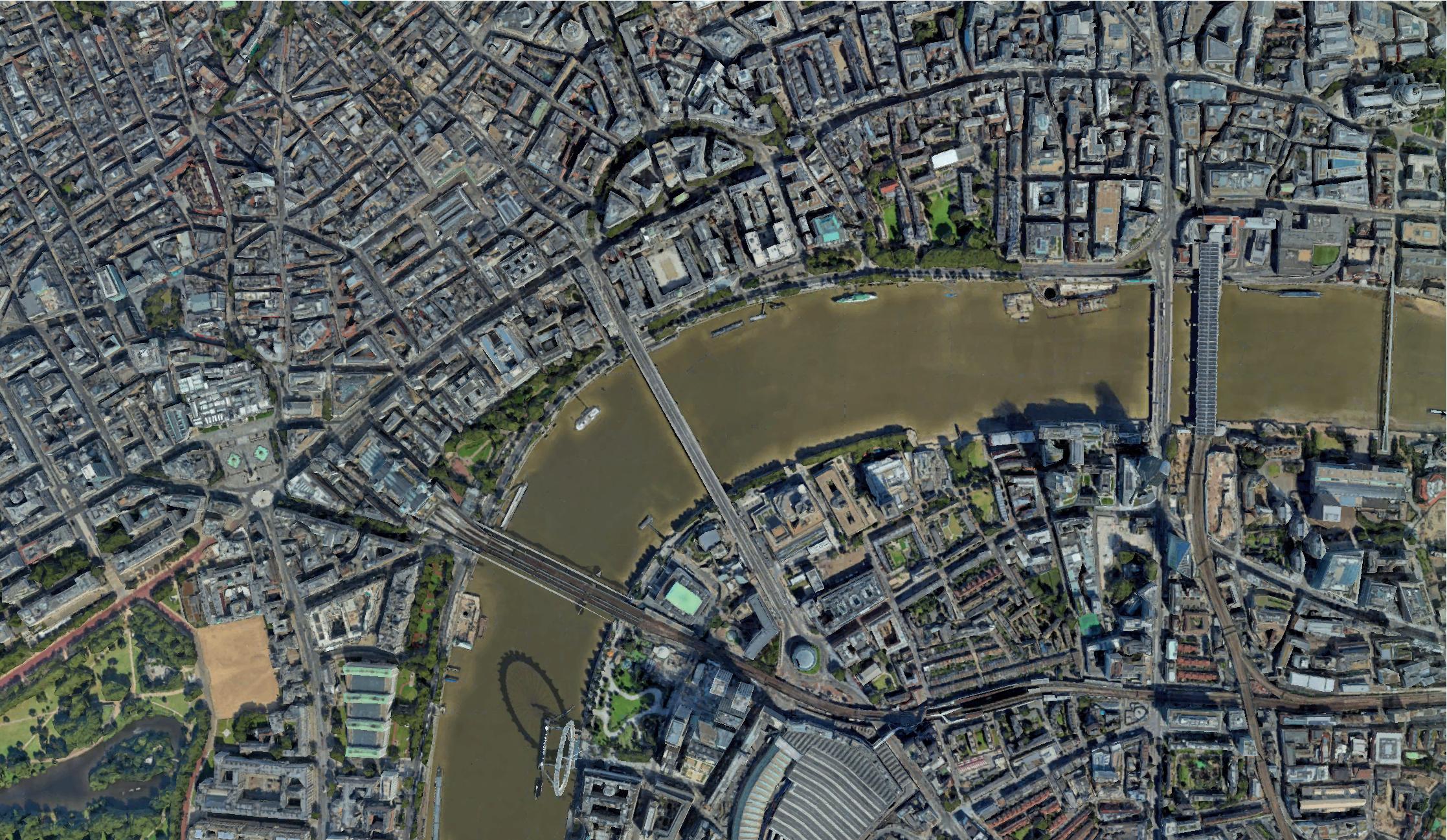
The site is located on the Northern embankment of the Thames, between Waterloo Bridge and Blackfriars Bridge, at Temple station.
SITE BOUNDARY
The site is located on the North Embankment at Temple. It currently houses Temple Underground Station and the A3211.
GENERAL SITE BOUNDARY
The extended site for new green space encompasses the entire stretch of the North Embankment from Waterloo Bridge to Blackfriars Bridge.
EMBANKMENT EXTENSION
Possible area for the extension of the embankment into the river to create an active waterfront.
TIDAL EXTREMES
Visualising the high and low water for the Thames at the site to determine the opportunities available along the waters edge.
MAIN ROUTES
The scheme proposes the removal of the A-road running through the north embankment to capitalise on the opportunities the embankment offers to the city and its residents. The traffic will be redirected along the Strand and is part of an effort to reduce vehicles on London’s roads, and encourage cycling.
ACCESS POINTS
The linear site has multiple access points from different orientations. These access points should be considered to encourage seamless movement through the site.
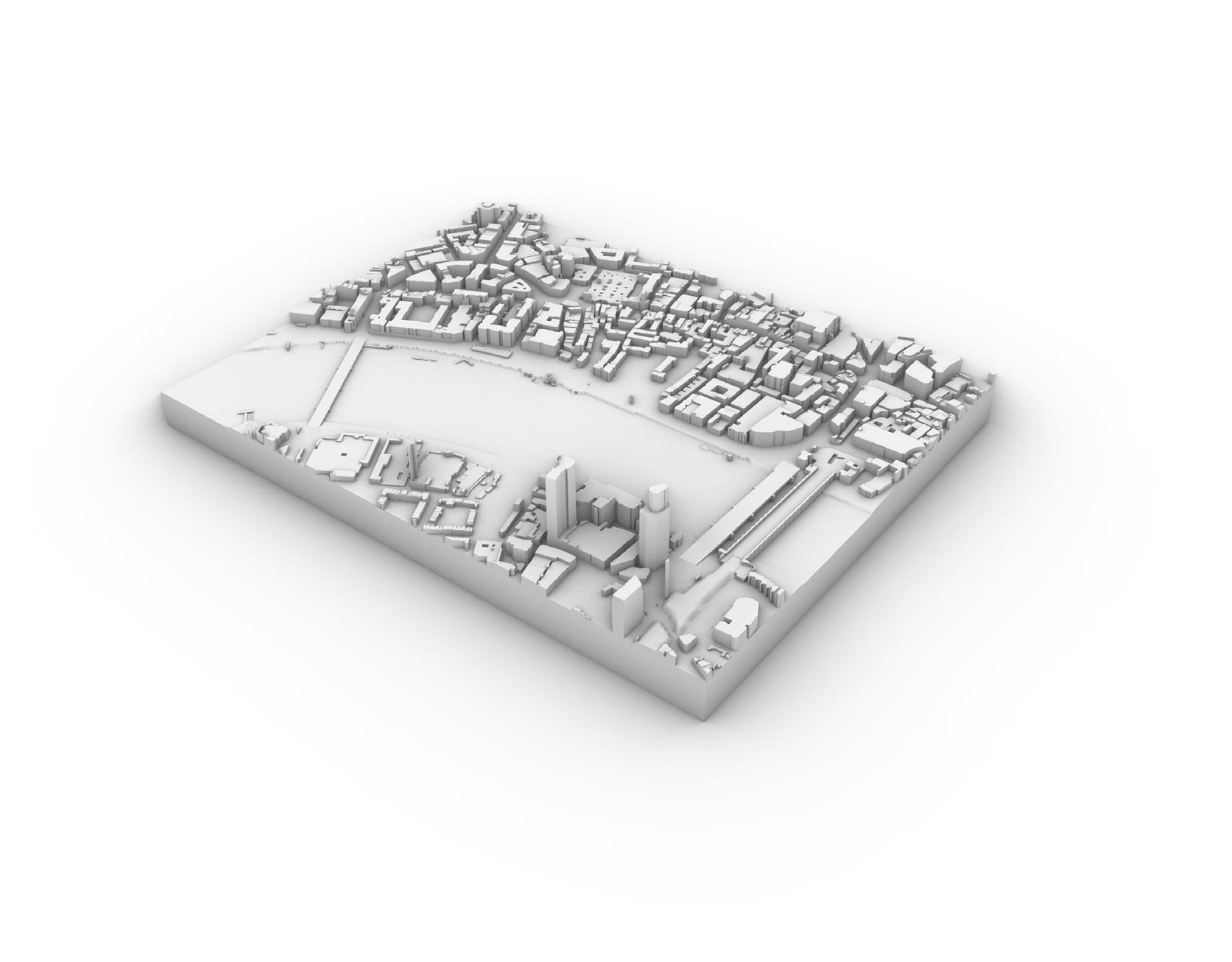


CONTEXTUAL CONSTRAINTS KEY DRIVERS
Visualising the main drivers in shaping the global form on site. These contextual constraints offer key information on how the building must respond to the site and its context.
SECTION 2 | CONTEXT & BRIEF
2.11
CENTRAL HUB
HIGHLINE HIGHLINE NODE
UNDERLINE
UNDERLINE NODE
CYCLE LINE PROPOSED NETWORK

SECTION 2 CONTEXT & BRIEF 2000m
2.12
Cycle Line, the name given to the new network that comprises of the Under Line and High Line, runs throughout the capital. The Under Line utilises the existing disused tube network, whilst the High Line runs over overground rail lines and occasionally the above the street.
03
SECTION 3: DESIGN DEVELOPMENT
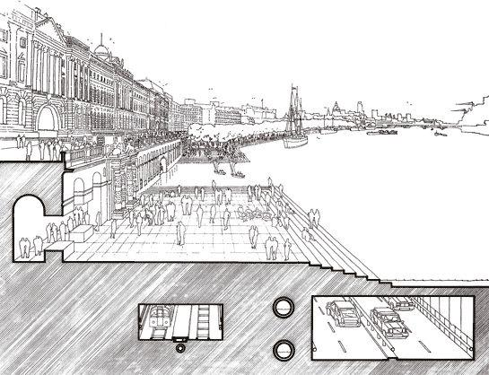
Creating a central hub in London that acts as a connection point to the 4 main transport networks. The hub will need to connect to the Under Line, High Line, pier and existing tube line. Each connection requires a different level/plane.
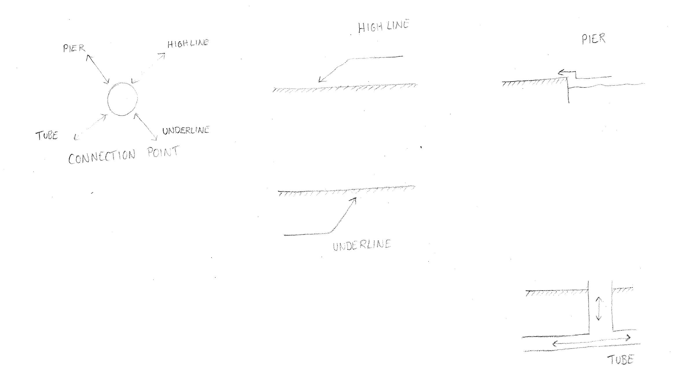


1. The High Line will connect from above, at a height around 4m.
2. The Under Line connects from beneath the ground, from existing tube tunnels.


3. The pier connects the water front to the embankment, the water level is also lower than the ground plane.
4. The existing tube station on the site requires a connection from underground to the ground plane.
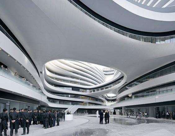
London as it could be’ - Rogers Stirk Harbour + Partners Concept of engaging with the river front using terracing
CONNECTION POINT HUB PROPOSAL
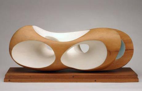
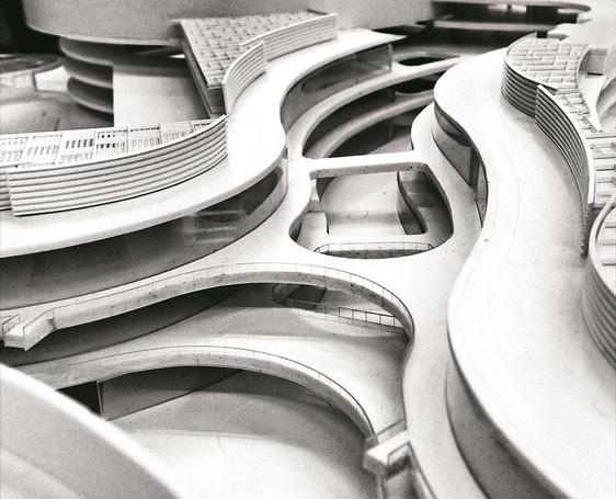
The project centers around a central hub in London that connects the new cycle infrastructure to the city and existing transport networks. The site at Temple allows the cycle network to connect not only the High Line and Under Line to one another and the ground plane, but also to the London underground and the London water taxi network. The requirement for multiple levels connecting to the ground plane lends the design to a canyon style form with multiple terraces. The need to connect to underground networks also informs the decision to build into the ground. This subterranean hub can therefore also free the ground plane along the embankment to become new green space in the city.

SECTION 3 | DESIGN DEVELOPMENT
Galaxy Soho, Beijing 2012 - Zaha Hadid Architects
Concept Model - DP Architects
A NEW TRANSPORT HUB:
3.01
Forms and Hollows - Barbara Hepworth Concept of opening a form to reveal a new condition inside.
Reversal - inhabiting the frame / free the ground plane by going under
DESIGN EVOLUTION
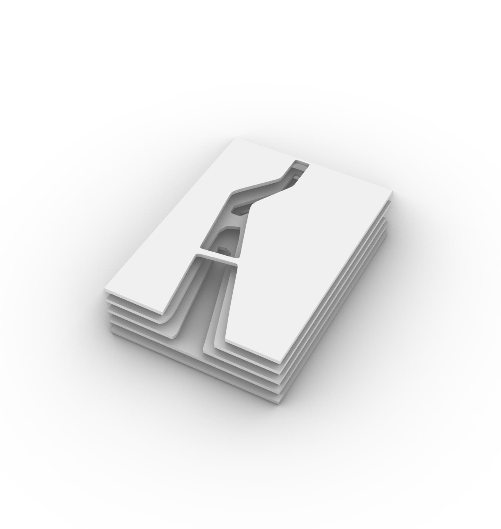

ORGANISATIONAL PRINCIPALS
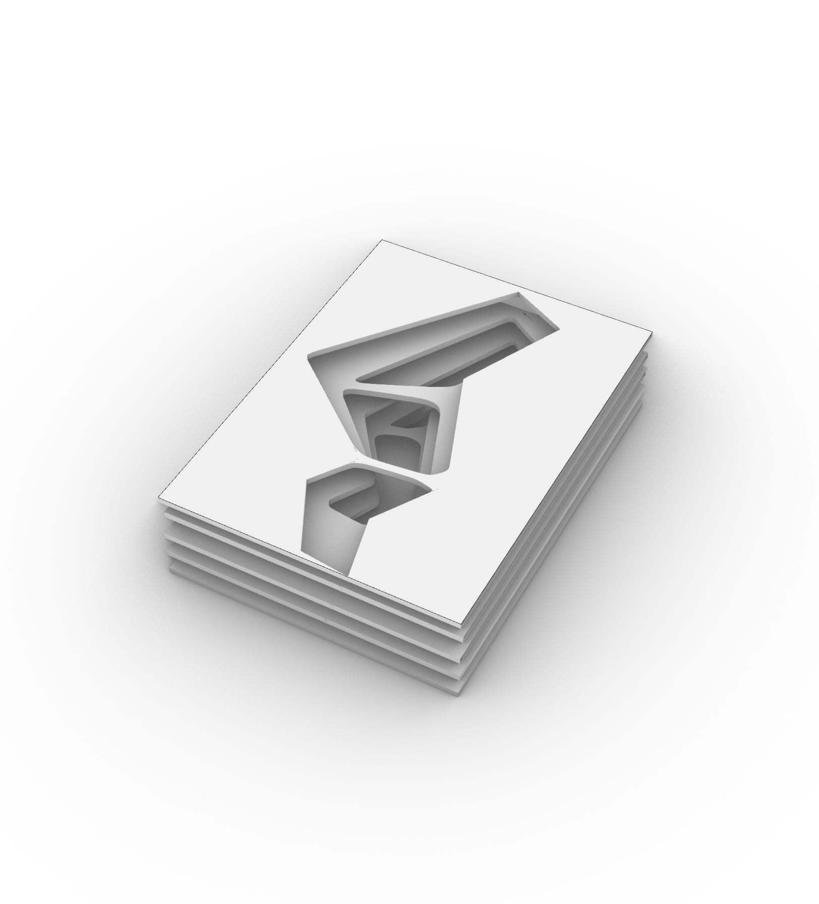
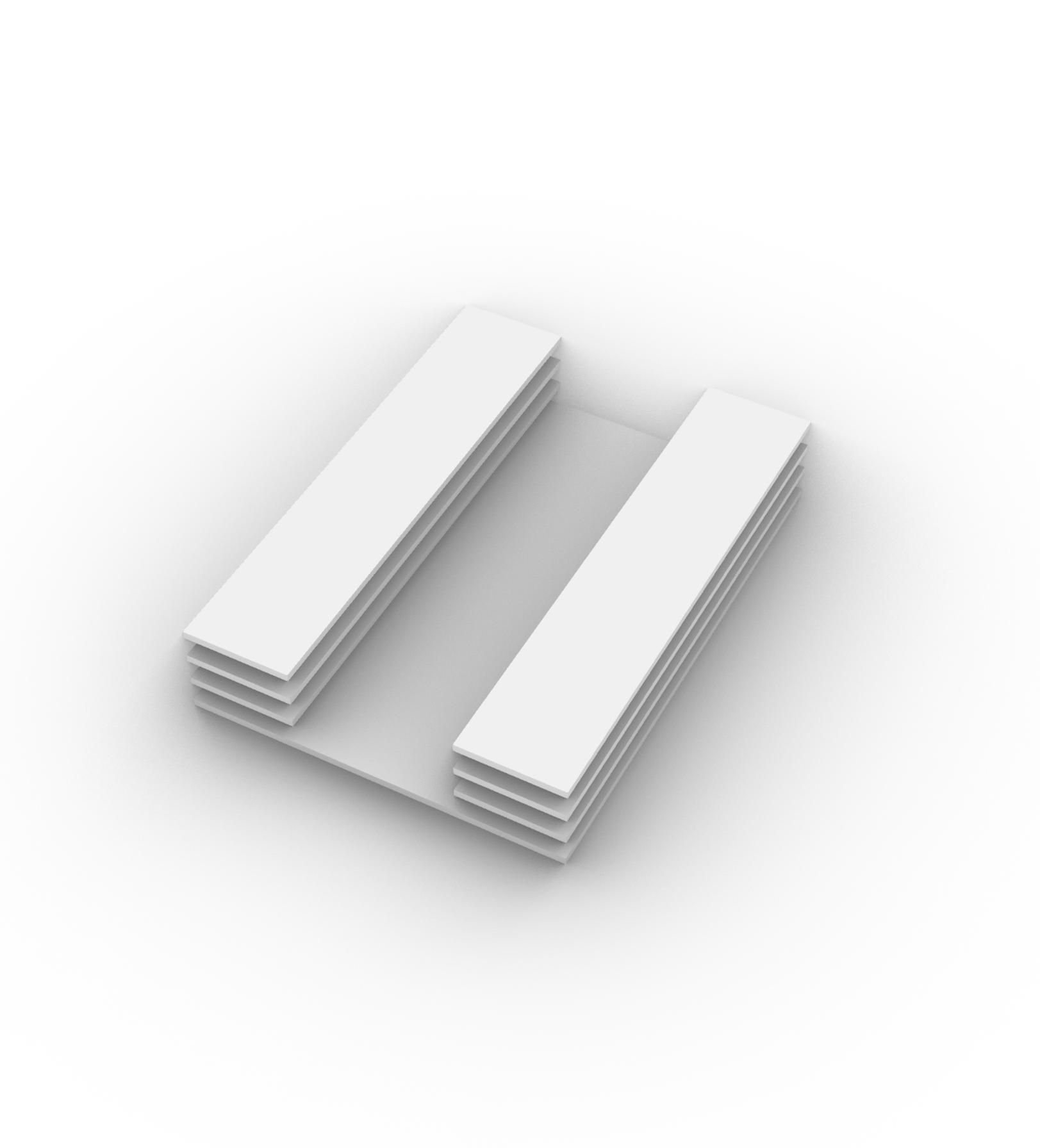
Prototypes for designing a canyon form. This uses the principal of freeing up the ground plane, but flips the narrative from inhabiting the roof frame to inhabiting a subterranean frame. These forms suggest using the horizontal plane as an organisational principal to develop an informed global form.





SECTION 3 | DESIGN DEVELOPMENT
1 2 3 4 5 6 7 8 9 3.02
One sloping plane to lower floor beneath ground, linear form above ground.
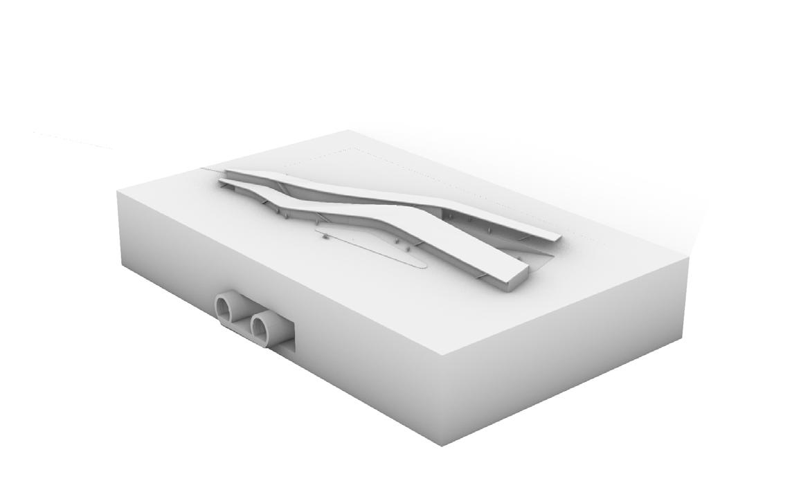
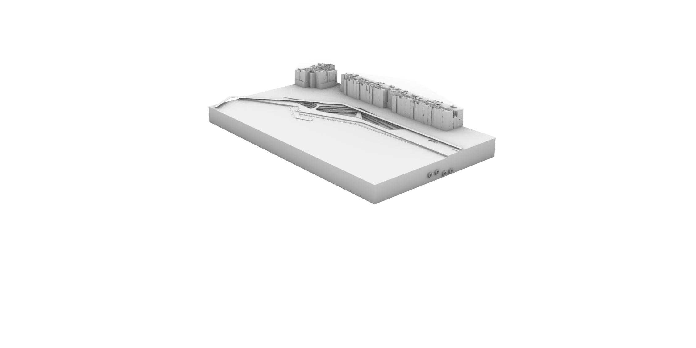

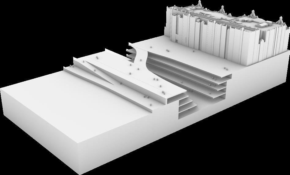
Testing the idea of the ground opening up to reveal a substructure beneath the surface, with a simple roof plane structure above ground.
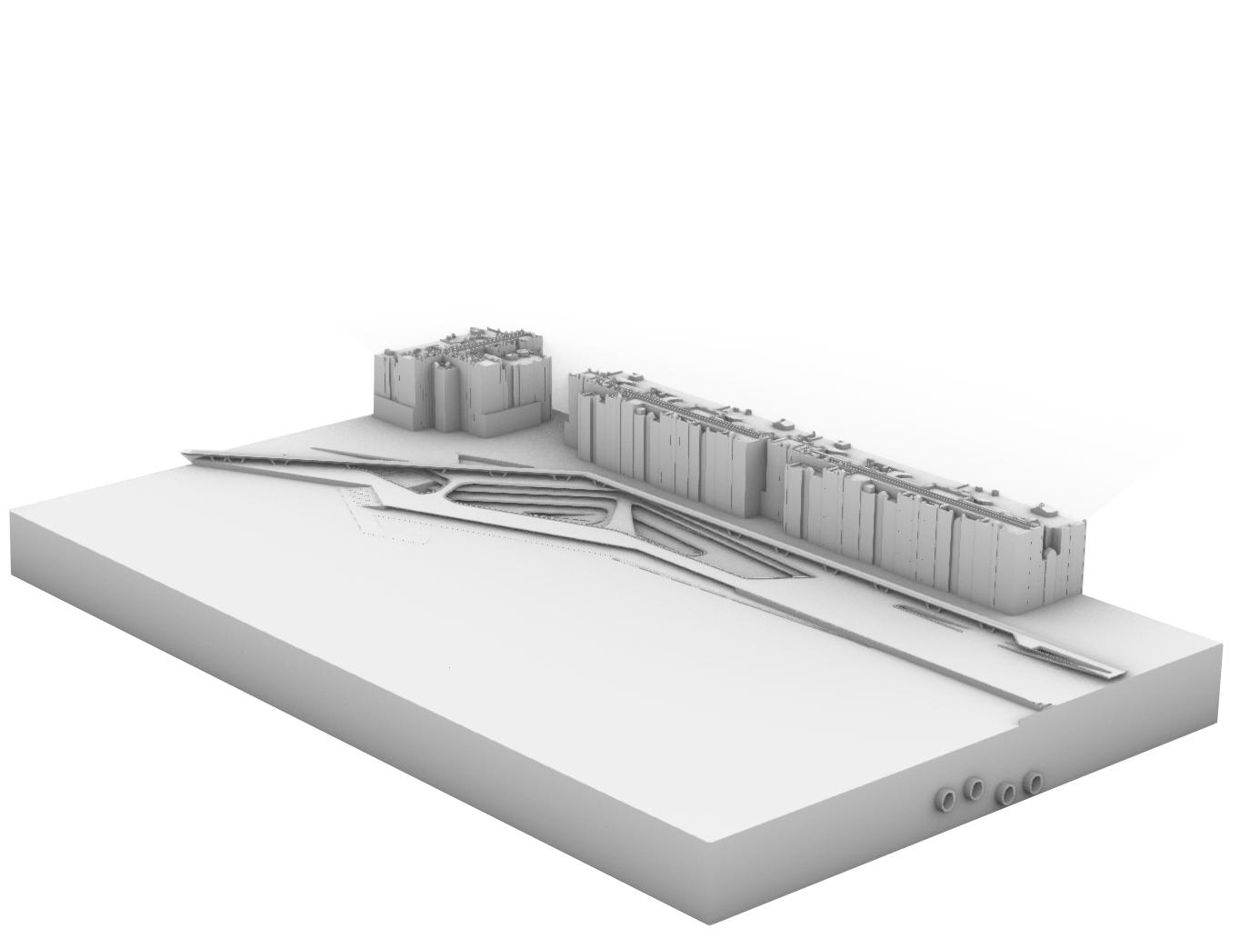
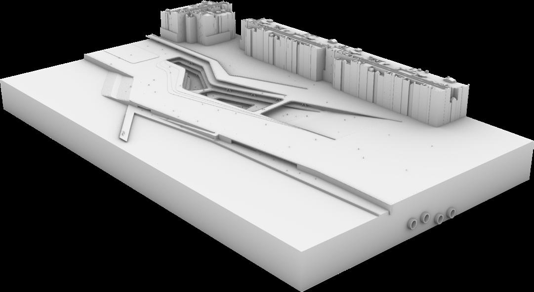
Experimenting with a fully subterranean structure, using undulating terraces to create a canyon style form. Also introducing a new interface with the Thames.
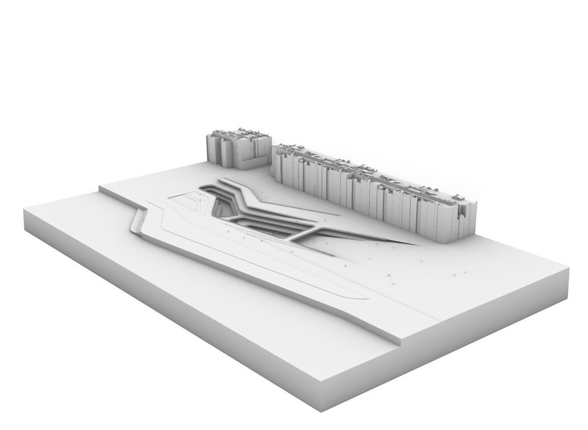
Introducing a large slope down into the canyon from the ground plane as well as a slope up to the Highline.
Further developing the global form, shaping the canyon to respond to the existing site, surrounding buildings and programme (High Line, Under Line and Hub).
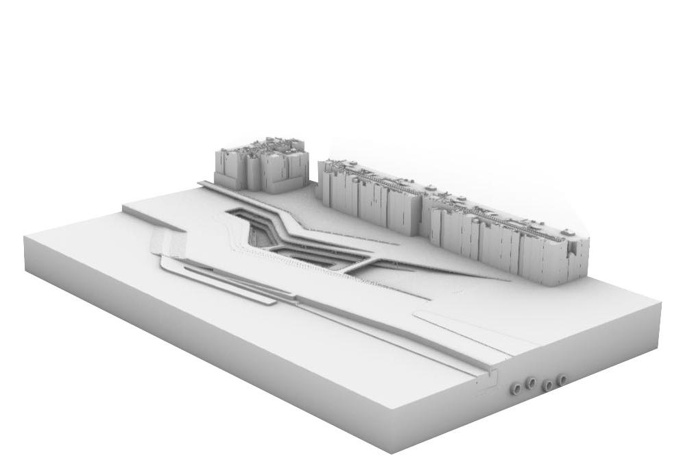
Testing a new waterfront terrace along the river that links into the lower level of the canyon, as well as a new pier.
Further refining the global form and shape of the canyon and its terraces to suit the site and programme. Testing the High Line running over the canyon.
Finalising the position of the terraces and the bridges through the canyon. The new terrace along the embankment engages the scheme with the River and the new Embankment Gardens.
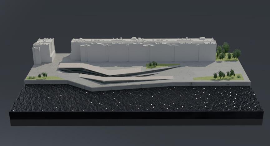
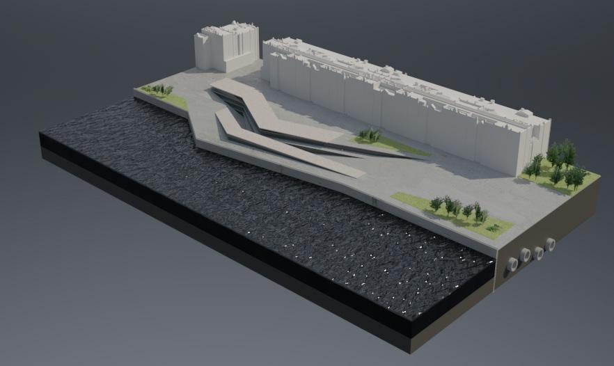
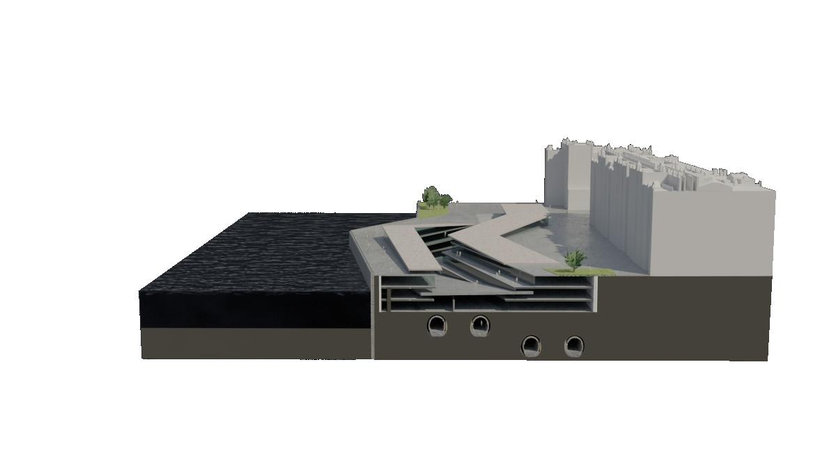
BUILDING GENESIS FORM TESTING
Various tests experimenting with the canyon form in the context of a riverside site and the Cycle Line programme.
SECTION 3 | DESIGN DEVELOPMENT
3.03
SECTION 3 | DESIGN DEVELOPMENT
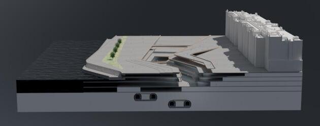
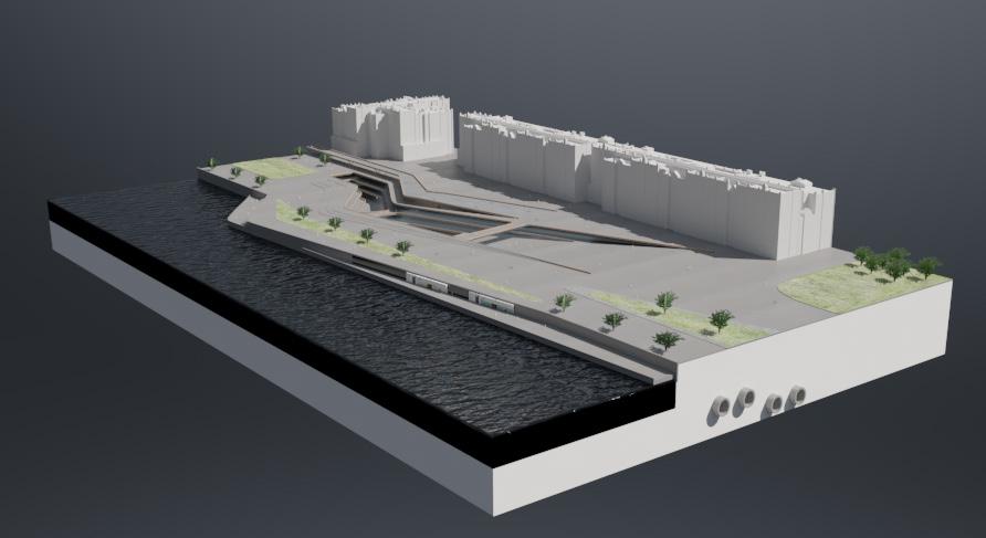
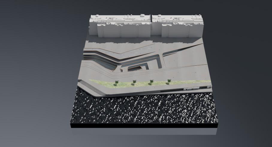
EXPLORATION Testing the principals of a canyon style form in the context of a riverside, city center site. These tests bring in elements of the programme such as the use of tube tunnels. Early tests included a simple roof plane continuing the structure above ground. 3.04
DESIGN TESTS FORM
DESIGN TESTS FORM EXPLORATION
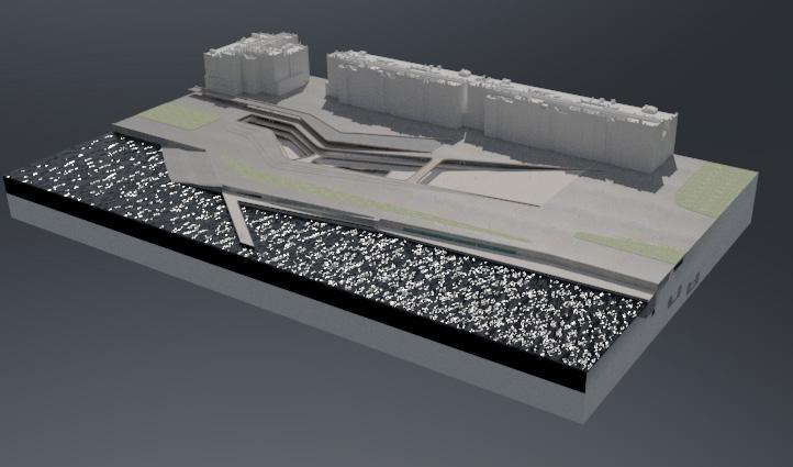
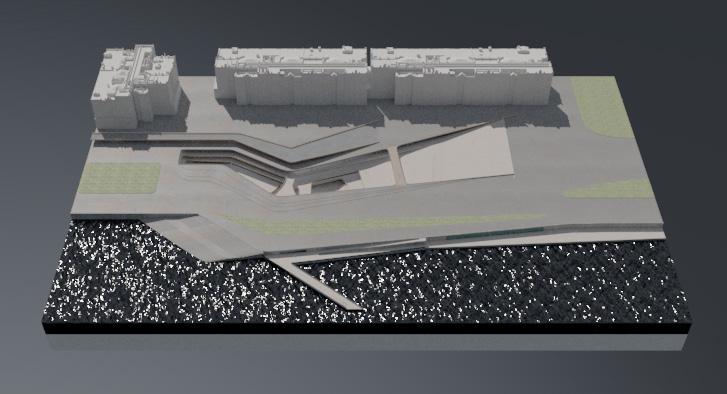
Further developing the global form to respond to the site and programme. This fragment also introduced the idea of developing a new embankment by engaging the scheme, and therefore the City, with the North bank of the Thames. The terrace would be accessed directly from the -1 level and would activate the waterfront with F&B.
SECTION 3 | DESIGN DEVELOPMENT
3.05
DESIGN TESTS FORM EXPLORATION
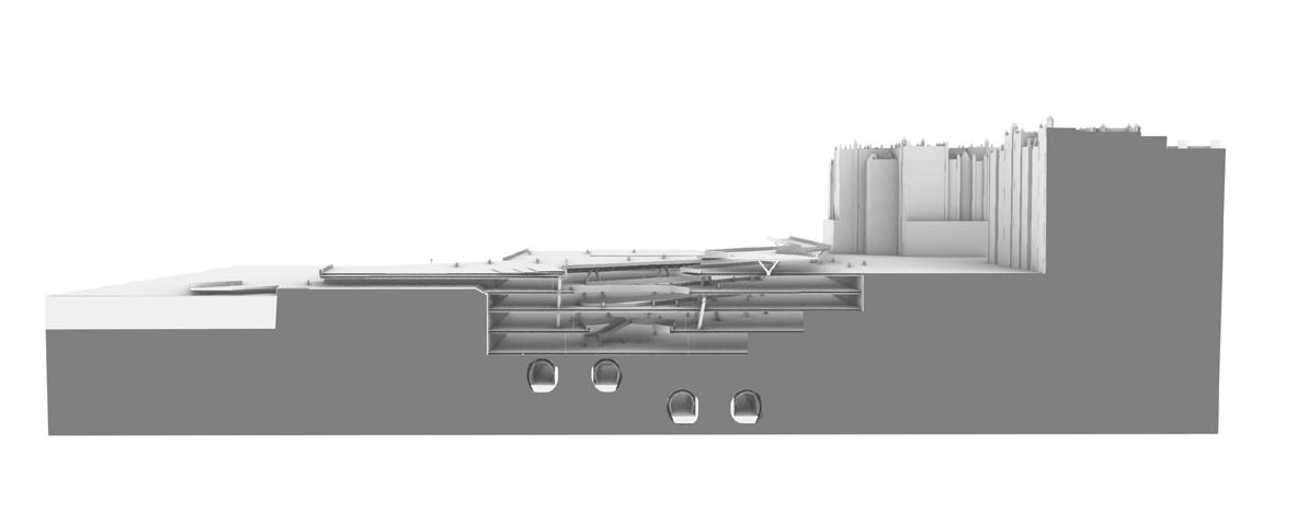
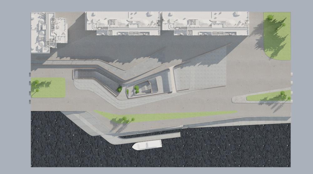
The global form is determined by access points from various parts of the site, as well as the movement of people through and around the site. The pier is first tested as an addition to the terrace, as well as the suggesting of new green spaces at ground level.
SECTION 3 | DESIGN DEVELOPMENT
3.06
DESIGN TESTS FORM EXPLORATION
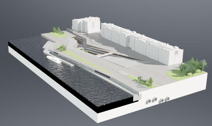
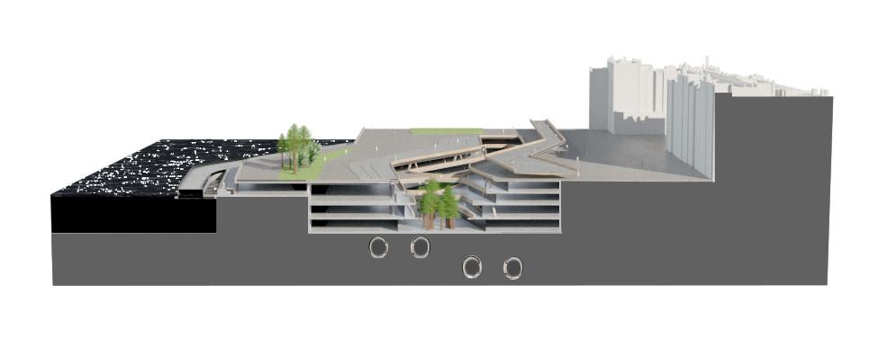
Developing a language to deal with the lines of movement around the site. The fragment starts to suggest the introduction of the timber frame to the inside of the canyon form, creating a contrast in the materiality and feel of the internal and external.
SECTION 3 | DESIGN DEVELOPMENT
3.07
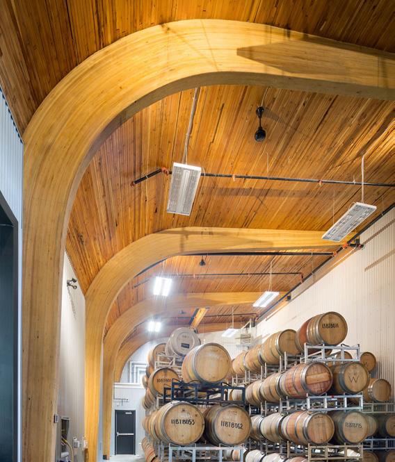
Testing forms and structural strategies for column design. The 45 degree angle of the column gives the structure more fluidity against the horizontal planes of the canyon structure.
COLUMN DESIGN STRUCTURAL STRATEGY
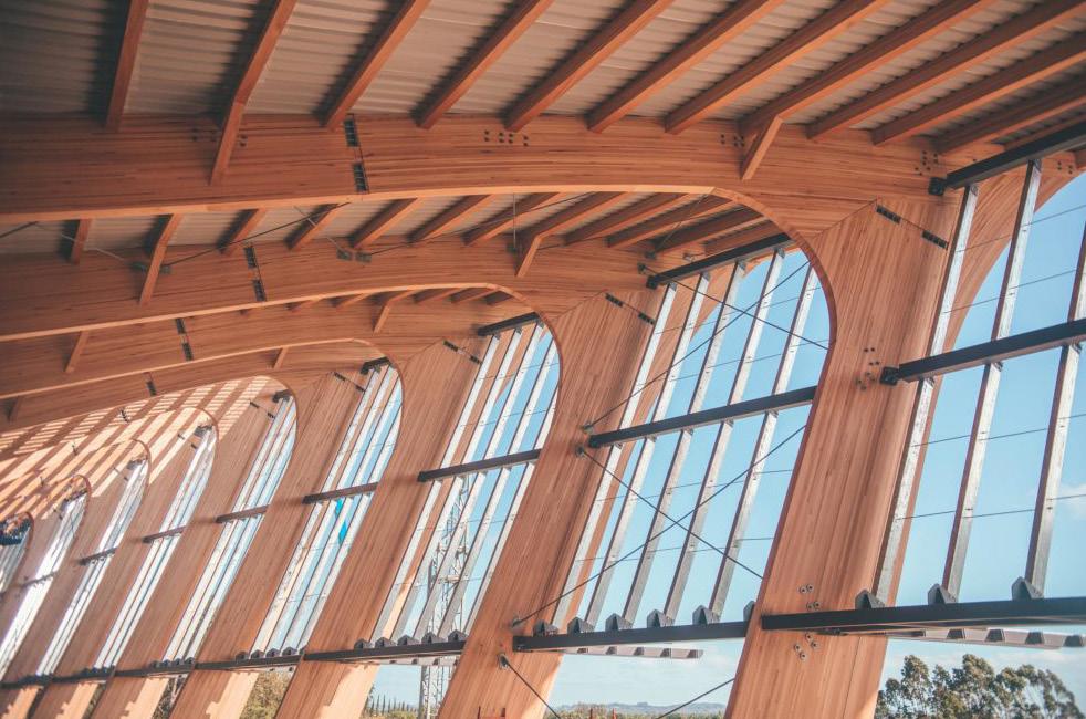
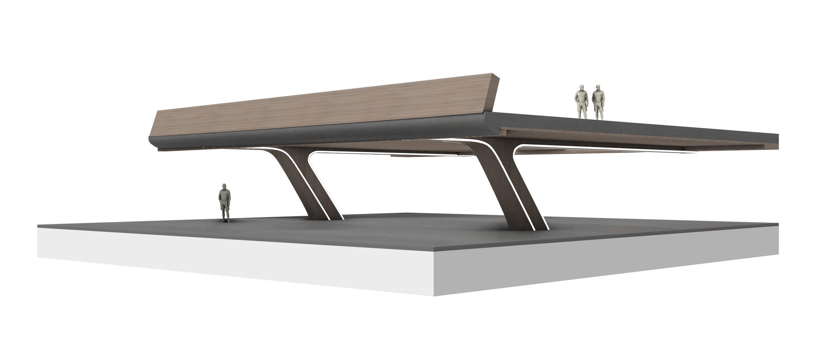
Most of the schemes horizontal floor planes can be supported by load bearing walls found on each level to house the programme. Additional structural columns are also required to deal with the large structural loads. Glulam columns and beams offer a solution to deal with these loads whilst also helping to reduce the buildings carbon footprint and reference back to the traditional English timber frame.
SECTION 3 | DESIGN DEVELOPMENT
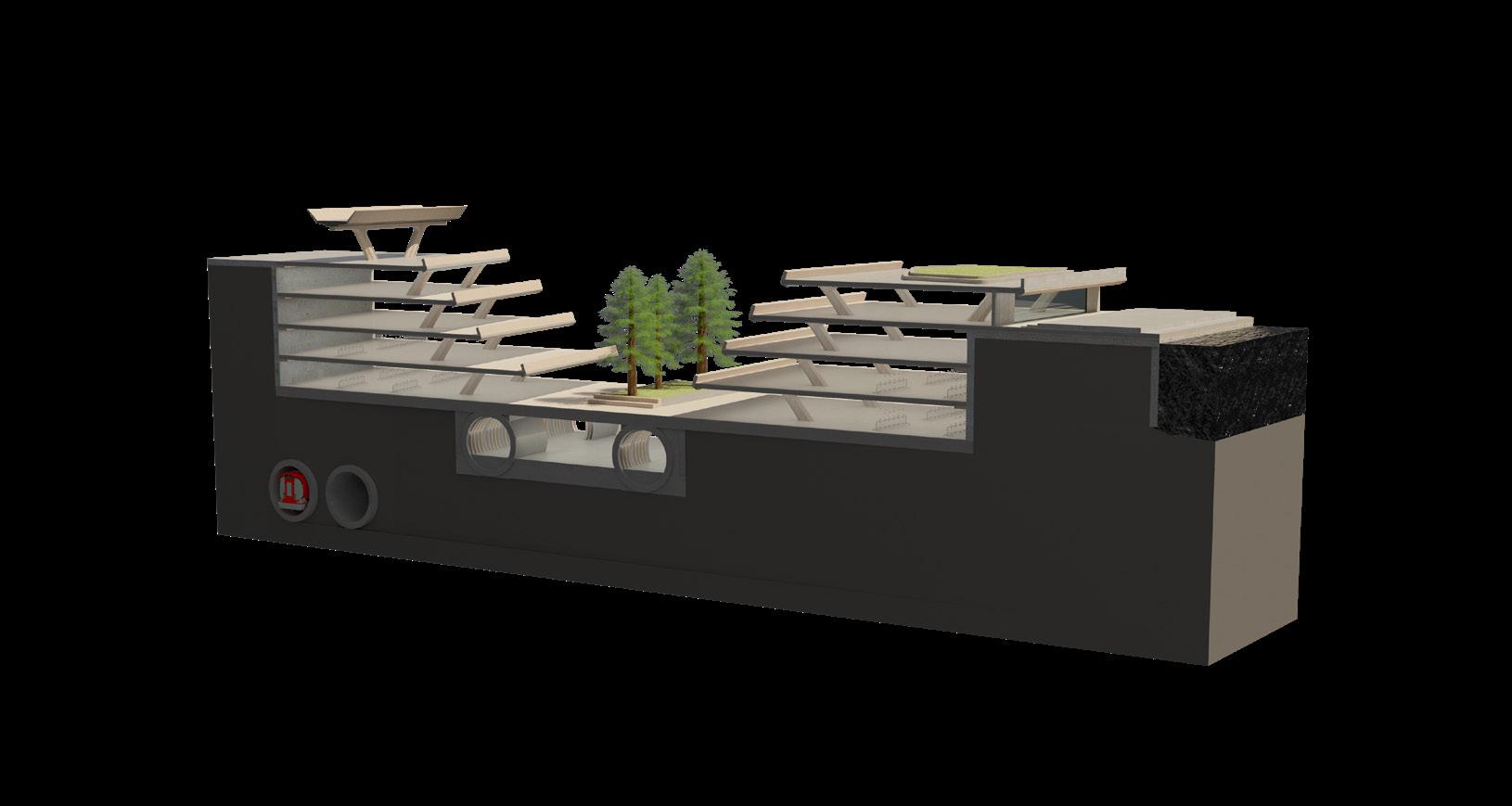
STRATEGY IN CONTEXT OF A CANYON FORM This simplified fragment tests the strategy in the context of a subterranean canyon style from.
COLUMN AND BEAM CONNECTION
3.08
hydraulic
hydromill
The
The


EXCAVATION STRATEGY
DIAPHRAGM
Precast
Ground
SECTION 3 | DESIGN DEVELOPMENT
1. PRE-TRENCH Excavation of top-soil using hydraulically-operated grabs
2. FIRST BITE Excavation of hard rock using a hydromill to penetrate by ‘cutting’ rather than ‘digging’.
3. SECOND BITE
hydromill continuously removes material and replaces it with bentonite. Bentonite forms a local cut-off barrier on the sides of the excavation
4. INTERMEDIATE BITE
bentonite barrier keeps the excavation open by applying a hydrostatic pressure that counteracts with earth pressure
5. GUIDE WALLS Construction of two parallel guide walls to keep the precast panels in place
6. PRECAST PANEL INSTALLED Precast panels lowered into trench
7. PRECAST WALL ASSEMBLED Units are installed in a trench filled with bentonite
8. DIAPHRAGM WALL INSTALLED
anchors are used to tie the panels to the retained earth to provide stability
grab
9. EXCAVATION Hydromill used to excavate rock from within diaphragm wall boundary, excavated rock is used to build the new embankment.
10. SHAFT CLEARED Excavation complete, shaft drained and excess material removed
11. HORIZONTAL BRACING
horizontal floor slabs installed via notches in the diaphragm walls, which also work as props to support structure laterally
WALLS
3.09
Diaphragm walls are used to support the earth during and after excavation. The horizontal floor plates, along with the angled structural columns support the external walls against the internal forces from the earth.
ELEVATED TYPOLOGIES
LANDING RAIL ROAD CYCLE PEDESTRIAN
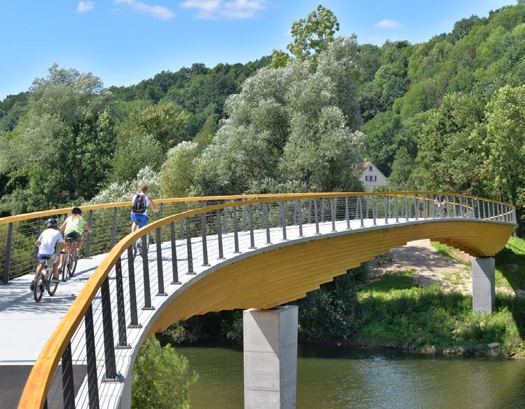
CURVED GIRDER BRIDGE NECKARTENZLINGEN - INGENIEURBÜRO MIEBACH
With a width of 3m it provides enough space for pedestrians and cyclists. The S-shaped design is oriented to the connecting infrastructure. For an efficient utilization of material the cross-section is graded according to the stress usage. The continuous beam creates moment diagram with zero crossings in the main span, which are designed as so-called Gerber hinge. In this way the design achieves sensible transport dimensions and a simplified assembly.
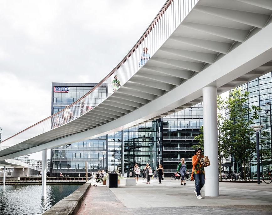
BICYCLE SNAKE - DISSING+WEITLING
The bridge is a painted, airtight welded steel structure, carried by a central steel spine – a 75 cm box girder, from which a series of cantilevered struts, made of folded steel plates, carries the steel plate deck. The structure is slim, with all parts being structural, hereby reducing the visual impact. We have strived for transparency and simplicity. Structural refinement. The parapet is perceived as a transparent film, no modular hierarchy. In essence underlining the fluidity of movement through space. The parapet consists of inward leaning steel bars with a circular cross section with a stainless steel handrail.
XIAMEN BICYCLE SKYWAY - DISSING+WEITLING
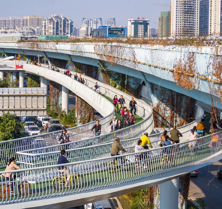
Xiamen Bicycle Skyway is the world’s longest bicycle bridge. an answer to the increased traffic congestion and pollution. It helps solve a pragmatic transport-related problem, while at the same time make a city greener. The bicycle bridge is 8-kilometres long and runs along and underneath the city’s existing overhead BRT skyway in the central part of the city. It covers the city’s five major residential areas and three business centers. There are 11 entries to the path, which will connect with 11 bus stations and two subway stations.
HIGH LINE PROPOSAL
ELEVATED NETWORK TYPOLOGIES AND PRECEDENTS
Elevating dedicated cycle paths above the ground allows cyclists, drivers and pedestrians to live together in harmony, reduce the risk of road traffic accidents and reduce carbon emissions from increased traffic due to road based cycle lanes. Providing a safe and efficient route via bike will not only reduce incident numbers, but increase cyclist numbers.

SECTION 3 | DESIGN DEVELOPMENT 3.10 2000m
PROPOSED HIGH LINE NETWORK
INHABITING THE TIMBER FRAME / FREEING THE GROUND PLANE

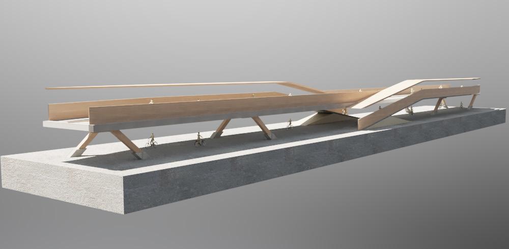
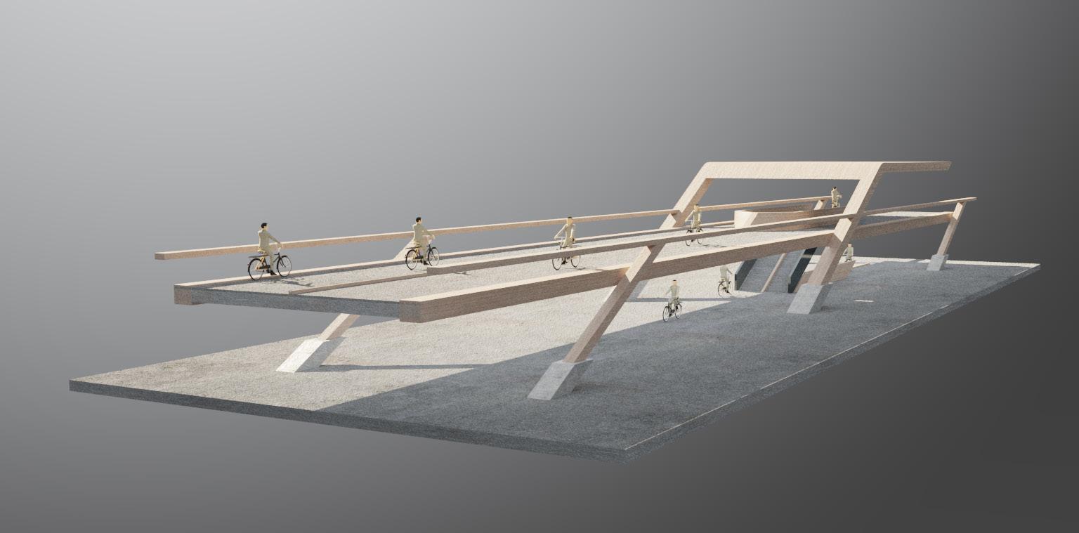
HIGH LINE TESTS FORMALISATION
Experimenting with the design of the elevated platform for the High Line. These tests link back to the early research into the timber frame and inhabiting the roof/freeing up the ground plane. Using timber as a material choice is unexpected when considering infrastructure in London. Timber therefore can help the High Line become a symbol for driving sustainable design in London.


SECTION 3 | DESIGN DEVELOPMENT
3.12
Testing how the High Line could connect to the ground and Under Line
Table top approach
Centralised column
HIGH LINE STRUCTURE DESIGN PROPOSAL

SECTION 3 | DESIGN DEVELOPMENT 3.13
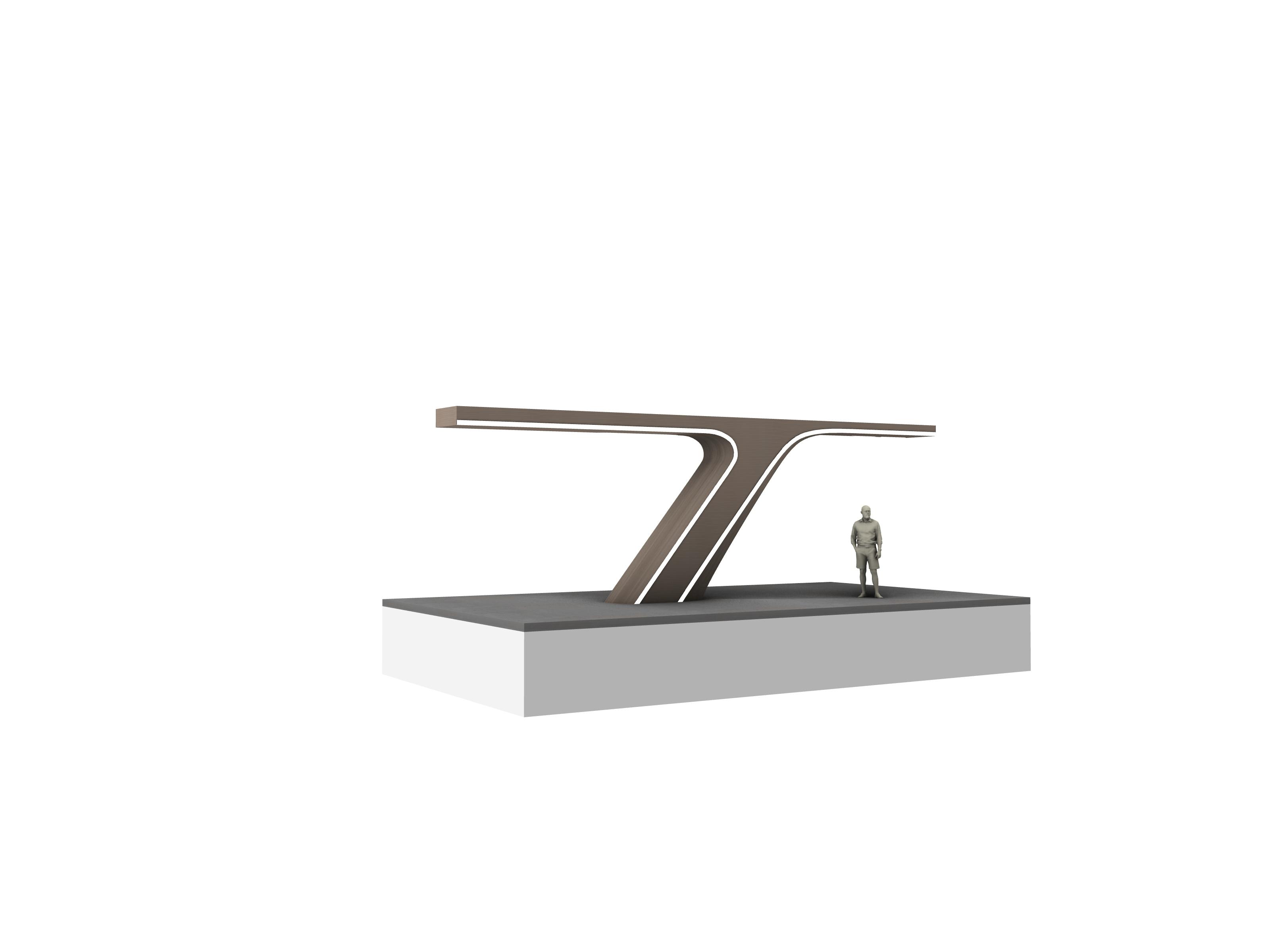
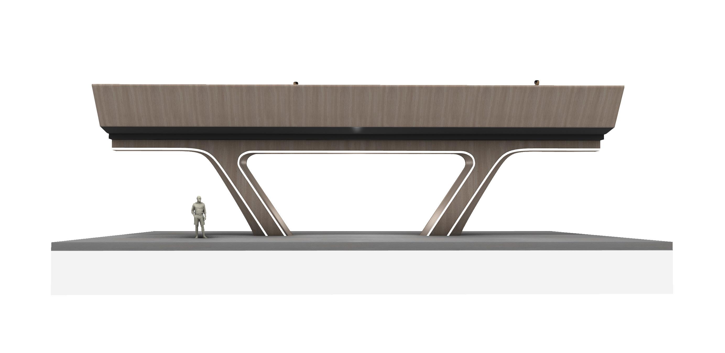
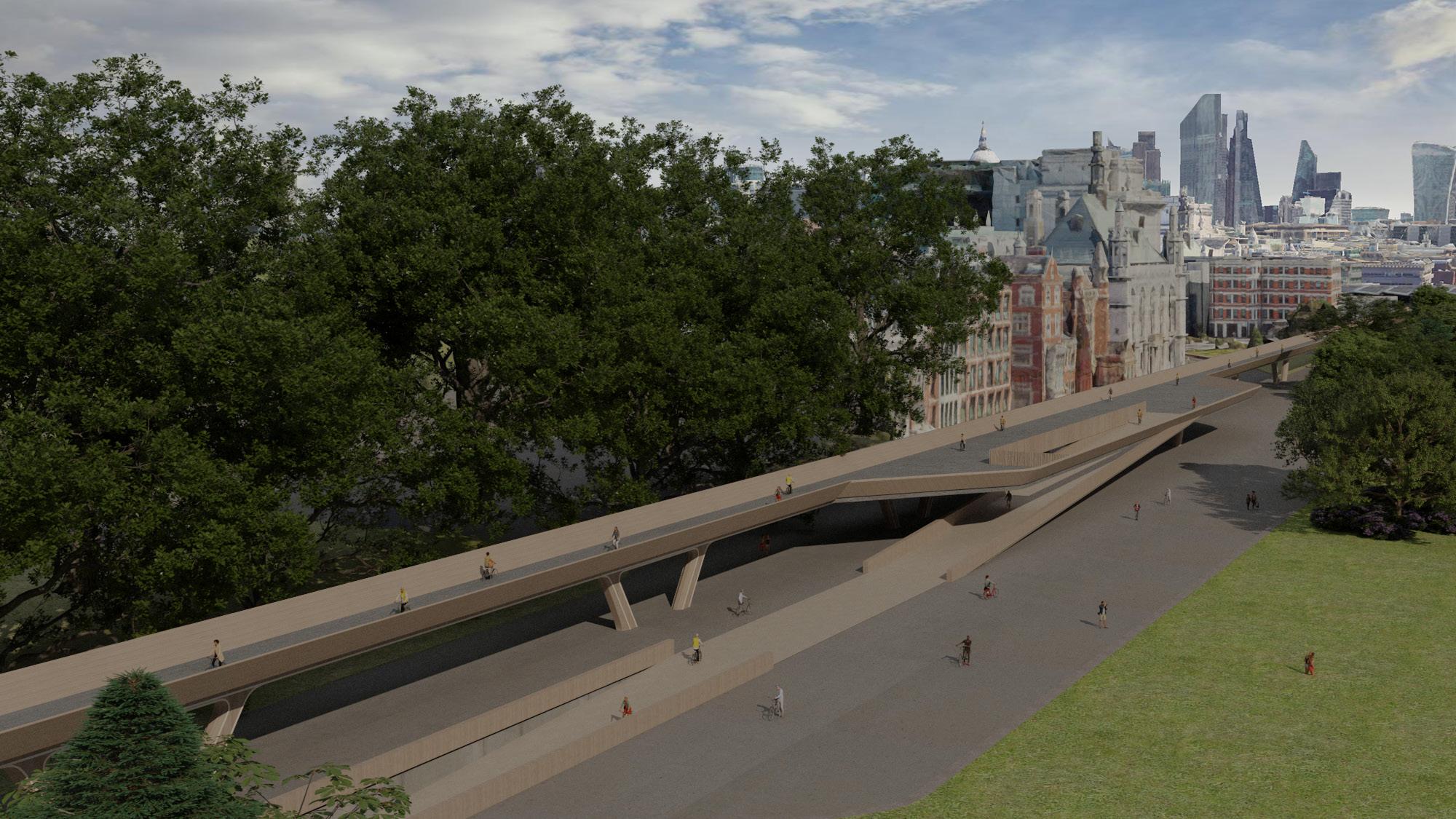
The High Line proposes elevated cycling platforms. This fragment tests the idea of a raised platform above the ground plane for safer, quicker and more efficient travel by bicycle around London. Glulam columns feed into a central beam running beneath the deck to create a fluid and dynamic design. The structure features LED lighting along the columns and underside of the deck to ensure the area below is well lit.
HIGH LINE DESIGN PROPOSAL
SECTION 3 | DESIGN DEVELOPMENT 3.14
The High Line proposes elevated cycling platforms. This fragment tests the idea of a raised platform above the ground plane for safer, quicker and more efficient travel by bicycle around London. Glulam columns feed into a central beam running beneath the deck to create a fluid and dynamic design. The structure features LED lighting along the columns and underside of the deck to ensure the area below is well lit.
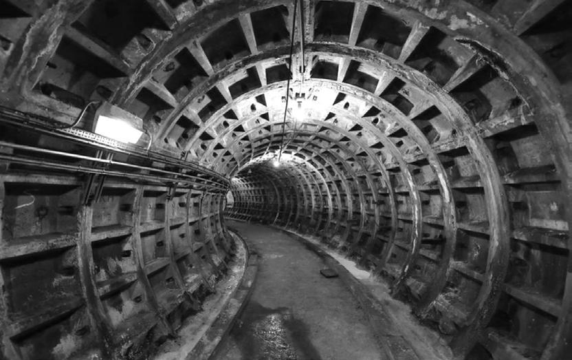
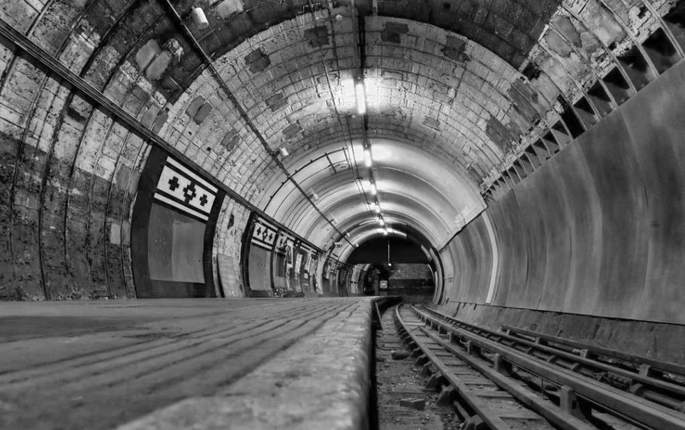
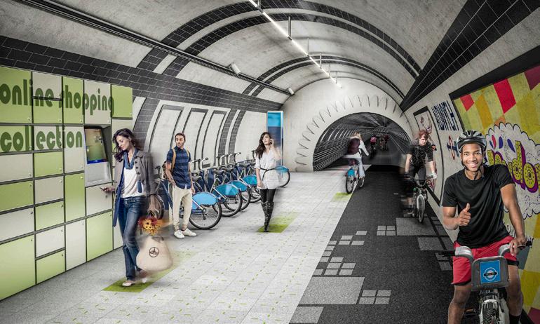
The London Underline proposes a city-wide connection by reinventing its existing infrastructure. Forgotten metro tunnels provide the space, catering to the ever growing demands for public transportation networks without the challenge of imposing them onto the bustling streets above. Additionally, the London Underline offers cultural and retail spaces throughout the network, encouraging public interaction below street-level by providing community space.
UNDER LINE PROPOSAL REGENERATING EXISTING INFRASTRUCTURE
There is a network of abandoned tube tunnels under London. The scheme proposes to regenerate this existing infrastructure for use as cycle paths. Similar proposals by practices such as Gensler consider how these tunnels could be re-imagined to become habitable for cyclists.

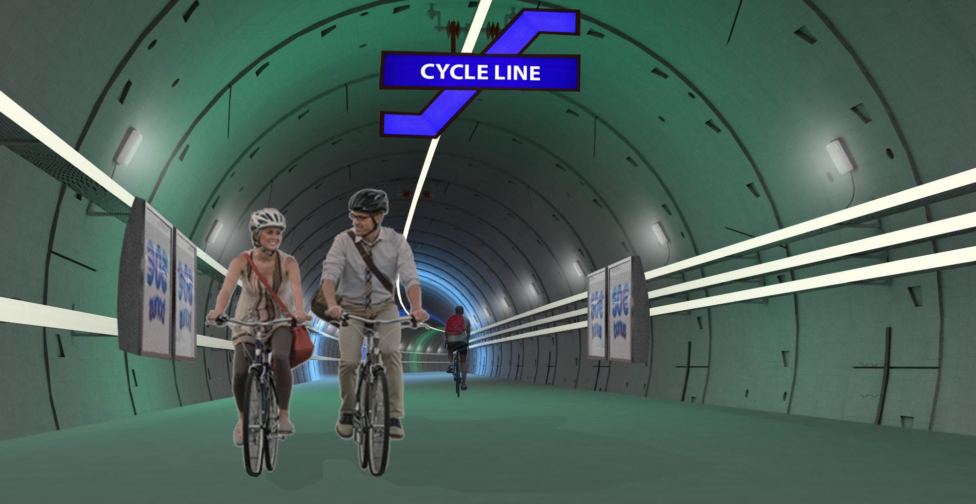
SECTION 3 | DESIGN DEVELOPMENT
3.15
LONDON UNDERLINE - GENSLER
UNDER
LINE EXISTING INFRASTRUCTURE - LONDON’S ABANDONED
TUBE TUNNELS
FRAGMENT IMAGINING TUNNELS AS CYCLE PATHS
SECTION
DESIGN
04
4:
PROPOSAL
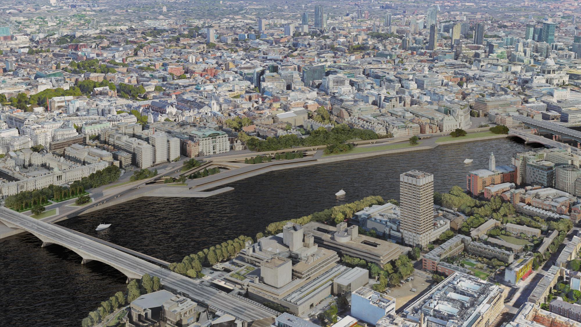
SECTION 4 DESIGN PROPOSAL EMBANKMENT GARDENS THE NEW GARDEN EMBANKMENT IN THE CONTEXT OF LONDON 4.01
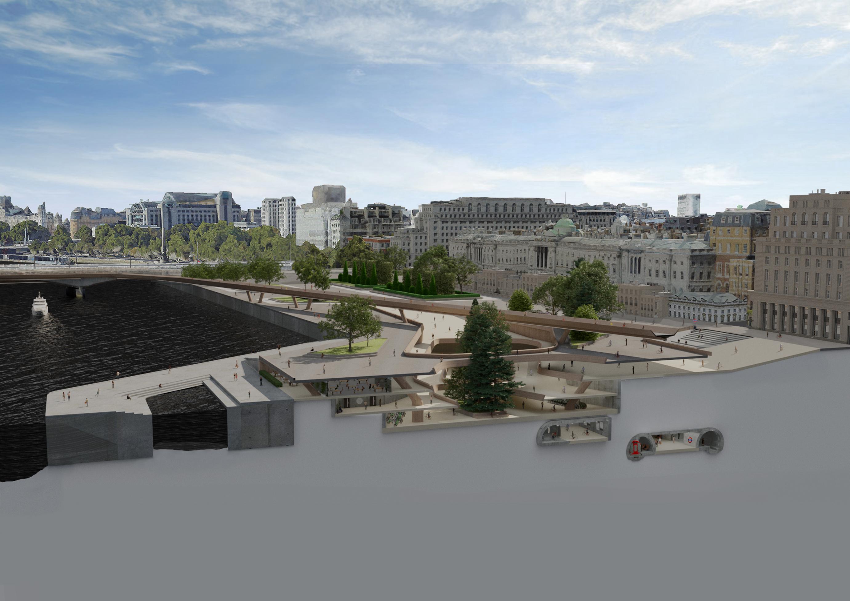
SECTION 4 DESIGN PROPOSAL CYCLE LINE THE SUBTERRANEAN CENTRAL HUB 4.02
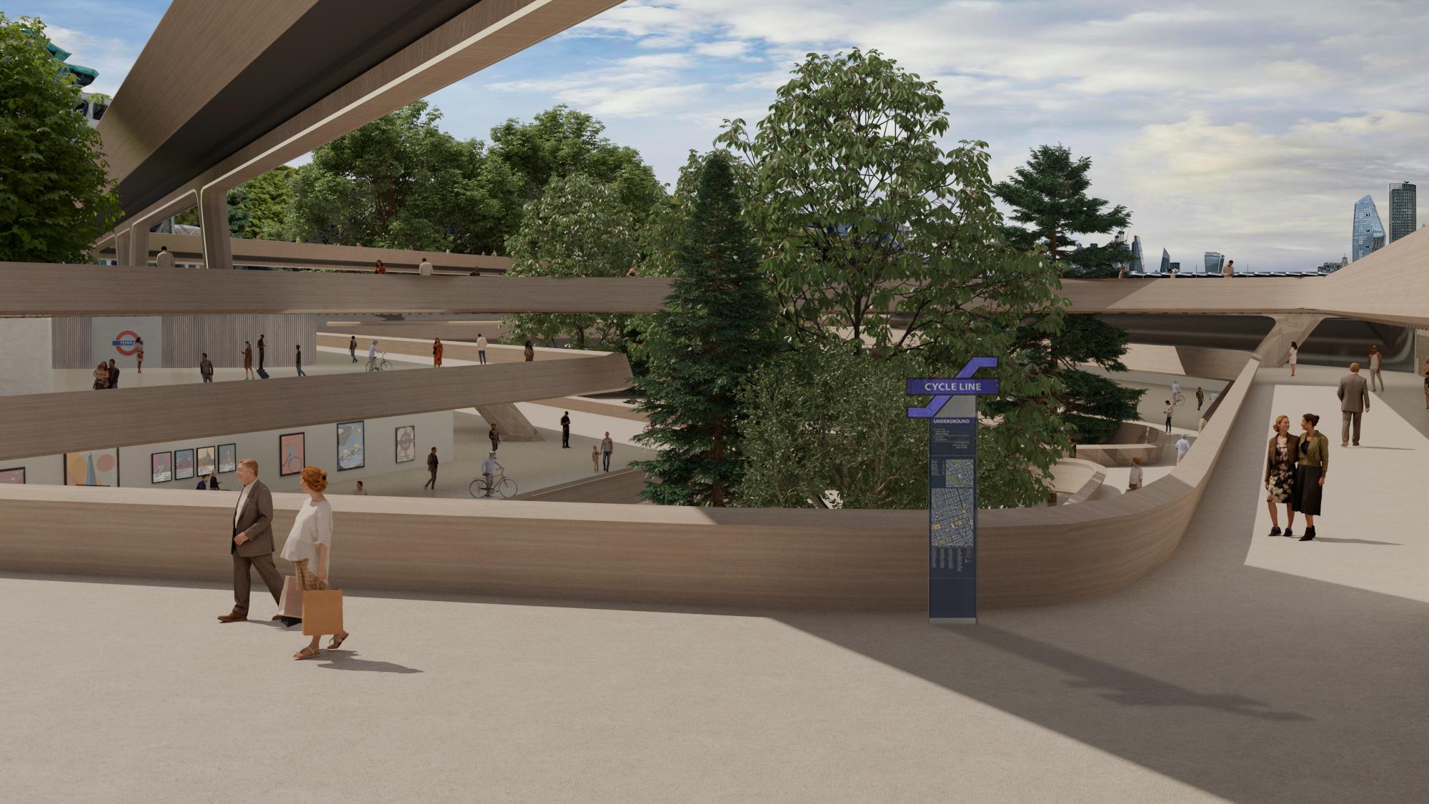
SECTION 4 DESIGN PROPOSAL CENTRAL HUB CIRCULATION THROUGH THE CENTRAL HUB 4.03
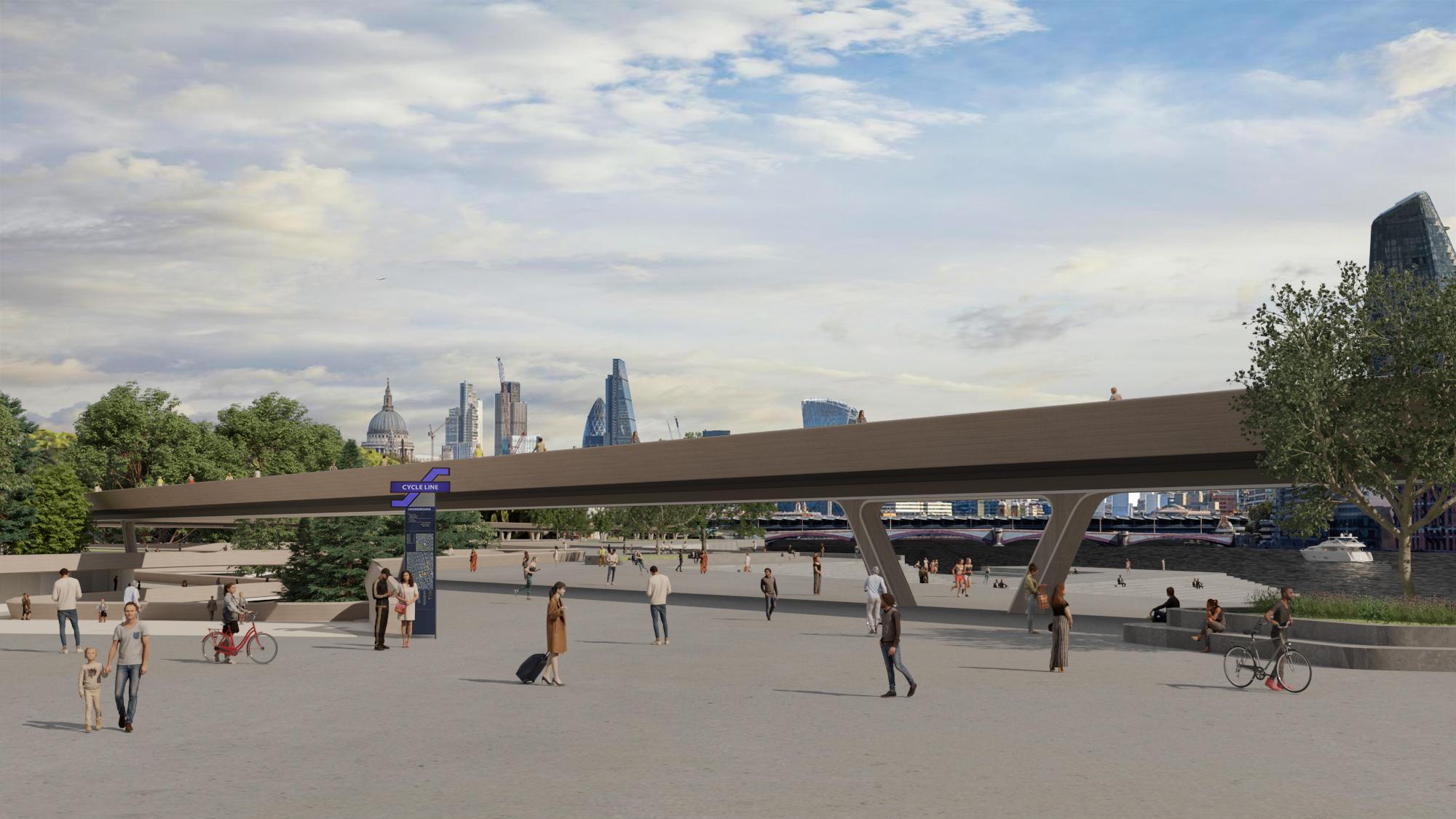
SECTION 4 DESIGN PROPOSAL HIGH LINE THE HIGH LINE PASSING OVER THE EMBANKMENT GARDENS 4.04
SECTION 4 DESIGN PROPOSAL SITE PLAN CENTRAL HUB IN THE CONTEXT OF THE NEW EMBANKMENT GARDENS 4.05
SECTION 4 DESIGN PROPOSAL UP TYPICAL PLAN LEVEL - 1 FLOOR PLAN - EXPLORING THE CONNECTION THROUGH THE CENTRAL HUB TO THE RIVERSIDE TERRACE 4.06
All work produced by Unit 14
Unit book design by Charlie Harriswww.bartlett.ucl.ac.uk/architecture
Copyright 2021
The Bartlett School of Architecture, UCL All rights reserved.

No part of this publication may be reproduced or transmited in any form or by any means, electronic or mechanical, including photocopy, recording or any information storage and retreival system without permission in writing from the publisher.

-

@unit14_ucl UNIT


 Cover design by Charlie Harris


