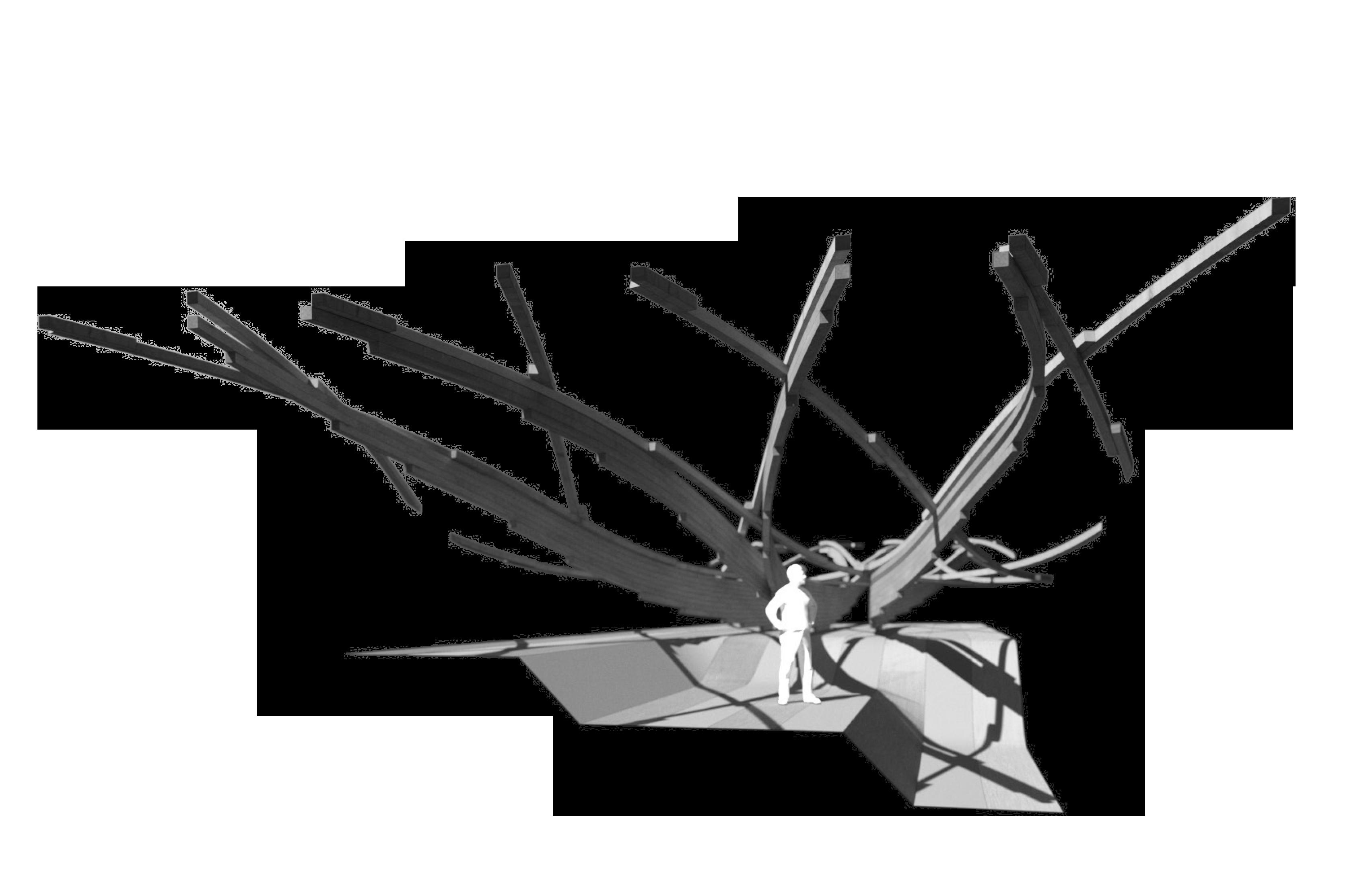
RESEARCH TOPIC
MATERIAL DISTRIBUTION
1
The Strategic Usage Of Material Distribution In Historic Timber Ship Construction
BACKSTAY MAINSAIL LEECH
MAIN CLEW BOOM
TILLER
REVERSE TRANSOM


RUDDER

2
MAST TACK FORESTAY BOW WATERLINE HULL KEEL
The Nordic Folkboat is a wooden 25 ft Swedish sailboat that was designed as a racer-cruiser and first built in 1942. In nautical history it has spawned various guises and several derivatives.
MAIN HEAD HEADSAIL/JIB
DECKING
BILGE STINGER
FUTTOCKS
FLOOR
WATERLINE
KEELSON
WOOD GRAIN DIRECTIONS / NORDIC FOLKBOAT 1942
The hull has a spooned, raked stem, a sharply angled transom, a keel-mounted rudder controlled by a tiller and a fixed modified long keel, with a cut-away forefoot.
GRAIN DIRECTION
PARALLEL LONGITUDINAL TANGENTIAL
3
MAST GUNWHALE LAPSTRAKES
IRON BALLAST KEEL
MAIN HEAD
BACKSTAY

MAINSAIL
TIMBER BATTENS
LEECH
MAIN CLEW
BOOM
TILLER
RUDDER
Yngling is a Norwegian sailing boat of 21 feet for regatta and day sailings. Jan Herman Linge designed Yngling in 1967 as a little sister to Soling and the idea was that it would be a recruitment boat for Soling.
TIMBER BATTENS FORESTAY
HEADSAIL/JIB
TACK

SPREADER PATCH HULL WATERLINE KEEL

4
MAST
FUTTOCKS
WATERLINE
FLANGED FLOOR
KEEL
WOOD GRAIN DIRECTIONS / YNGLING 1967
Yngling is a racing keelboat, built predominantly of fibreglass.. It has a fractional sloop rig with aluminum spars. The keelboat has flexible wood battens inserted into a sail, parallel to the direction of wind flow, that helps shape its qualities as an airfoil.
GRAIN DIRECTION
PARALLEL LONGITUDINAL TANGENTIAL
5
ALUMINIUM MAST
TIMBER BATTENS
FIBREGLASS
FORESTAYKSTAY
HEADSAIL/JIB
AIRFOILS

MAIN CLEW
DOUBLE HEADSAIL
HULL
Cheveyo steps away from the current norm of modern J’s aluminium fabrication process and returns to the historically accurate construction method, though with the use of modern epoxies and laminating techniques to maintain a constant grain direction for maximum performance yield.
TIMBER BATTENS
MAINSAIL


BACKSTAY
SPREADER PATCH
TACK
HULL
INTEGRATED RUDDER
WATERLINE
6
MAIN HEAD
LONGITUDINAL BOLTS LONG ARM
THROUGH-BOLTS
SHORT ARM
CHEVEYO FRAMES AND INTEGRAL JOINERY
Principal strengths of the frame is to keep the grain of the wood running parallel to the direction of the frame edge. The futtocks use integral joints, where forces between the parts are transferred through geometrical features rather than on the joints themselves.
7
3RD FUTTOCK
2ND FUTTOCK
4TH FUTTOCK
CILL
KEELSON
1ST FUTTOCK
TOP TIMBER
FLAT SCARF JOINT DOWEL-JOINT INTEGRAL JOINT
3RD FUTTOCK
2ND FUTTOCK
1ST FUTTOCK
KEEL
4TH FUTTOCK CILL
KEELSON
CONSTRUCTION OF FUTTOCK FRAMES
Joints between two futtocks are not located at adjacent heights primarily because splicing connections act as a weak point in the hull. Therefore the futtocks have different lengths to allow consistent shear connections between the scarf joints.
8
STAGGERING FRAMES
THINNEST MEMBERS
SHORT ARM
LONG ARM
SHEAR JOINT
KEEL FLAT SCARF JOINT
THICKEST MEMBERS
PARALELL GRAIN
PERPENDICULAR CUT
KEELSON
ONRUST 1614 / DOUBLE-SIDED FRAME
Onrust was constructed in less than four months in 1614. Due to its speedy completion, it is assumed the ship was built with the leftover parts from its successor, together with new building materials soruced locally,.
9
3RD FUTTOCK
3RD FUTTOCK
2ND FUTTOCK
2ND FUTTOCK
FIRST SHELL
1ST FUTTOCK
STERN LAPSTRAKE (CLINKER)
KEEL THROUGH BOLTS
BILGE FUTTOCK
TRANSOM
KEELSON
KEEL
LUMBER AS FRAMES AND FUTTOCKS
Lumber hero chart of typical framing dimensions and first futtocks sourced from solid wood. The bottom row illustrates the same scantling cut from timber of different curvature with direct application and use.
10
2x6 2x6
4x6 4x4
2x8 2x6
6x6 4x4 140
140
140mm flat-sawn bow crook twist cupping longitudinal rift-sawn diamonding curved quarter-sawn bulge edge straight
2x4 2x6 38 x 89mm 38 x 140mm 4x4 4x4 89 x 89mm 89 x 89mm
38 x 140mm 38 x 140mm
89 x 140mm 89 x 140mm
38 x 184mm 38 x 140mm
x 140mm
x
Sawn timber: SS-EN 1313-1 and SS-EN 336
CATEGORIES
NORWAY
11
/ CROSS-SECTIONAL SAWN TIMBER CHART
100mm 47mm 75mm 44mm 63mm 38mm 50mm 32mm 25mm 22mm 19mm 250mm 225mm 200mm 175mm 150mm 125mm 100mm 75mm 50mm 38mm 25mm 16mm 12mm
Chart of cross-sectional dimensions commonly occurring in sawn timber in Sweden and Norway. Sawn timber chart is sorted hierachial in dimensions of width and thickness.
JOIST PLANK
BEAM-AND-POST BATTEN BOARD
Planed timber: SS-EN 1313-1 and SS-EN 336
CATEGORIES
NORWAY / CROSS-SECTIONAL PLANED TIMBER CHART
12
33mm 28mm 70mm 18mm 45mm 15mm 12mm 9mm 21mm 220mm 195mm 170mm 145mm 120mm 95mm 70mm 45mm 33mm 21mm
Chart of cross-sectional dimensions commonly occurring in planed timber in Sweden and Norway. Planed timber chart is sorted hierachial in dimensions of width and thickness.
JOIST PLANK
BEAM-AND-POST
BATTEN BOARD
MATERIAL DISTRIBUTION
SCANTLING TECTONICS
Systems of Scantling Timber with Distinct Hierarchy for Performance and Program

13
surface shell

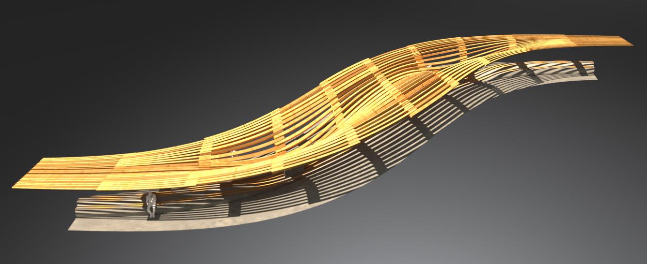
Area: 231m²
THICKEST BEAMS 20cm
THINNEST BEAMS 5cm
individual members
Total members: 220
SIMPLE MEMBERS-TO-SURFACE
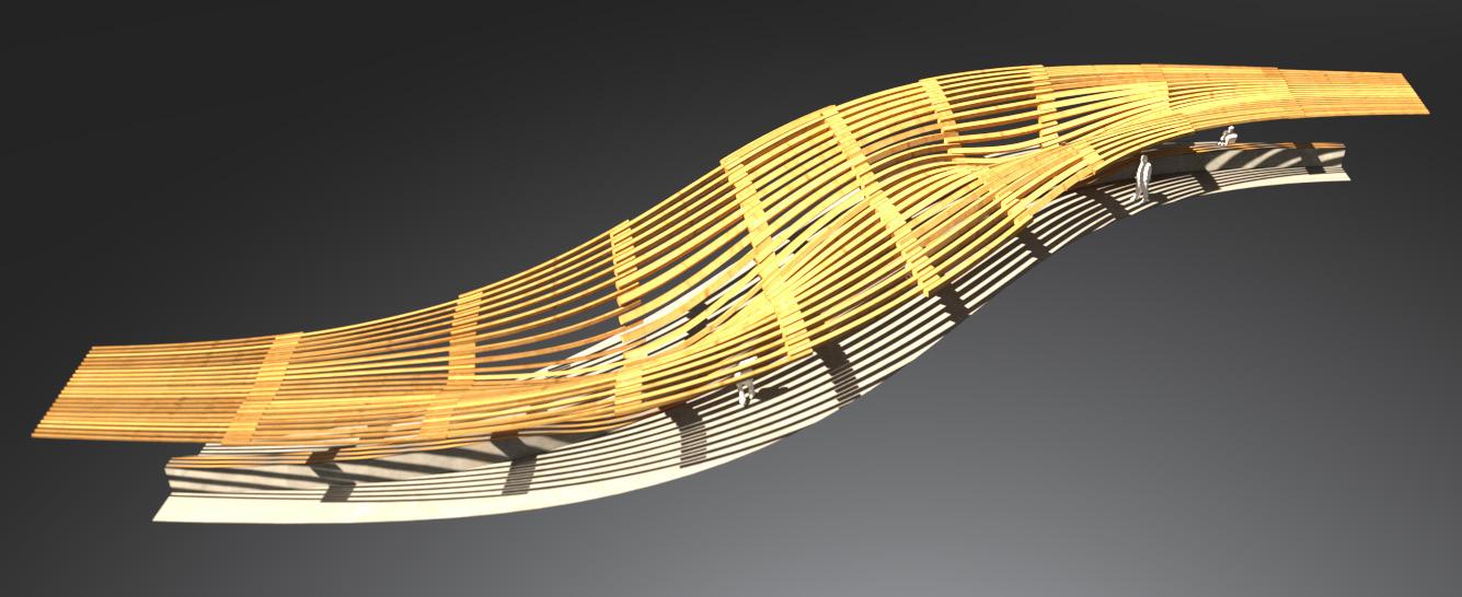
Rationalizing the main principals of the ship hull’s futtocks and applying its intrinsic logic of staggering timber battens. The simple members can be viewed as a series of interlapping beams spanning across various ranges to form a rigid surface.
14
FIRST FUTTOCK
COLUMN 40x115cm
STAGGER
1B FUTTOCK
2A FUTTOCK
2B FUTTOCK
1A FUTTOCK
right view left view
utilization
Upper threshold: 55
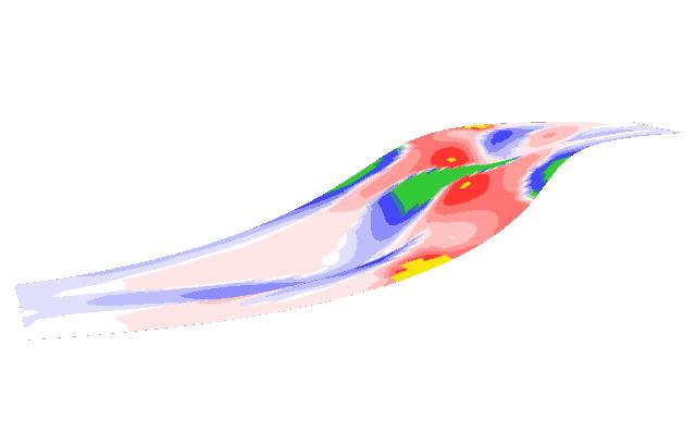
Lower threshold: 38
High compression
High tension
surface as shell
Upper threshold: 77
Lower threshold: 13
High displacement
Low displacement
surface as individual beams
grain direction
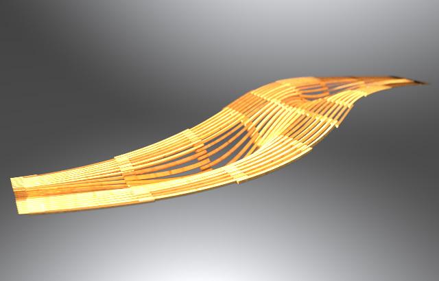
SURFACE AS INDIVIDUAL BEAMS
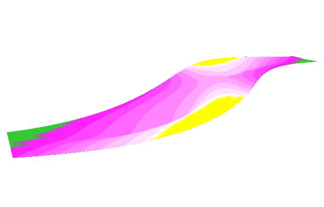
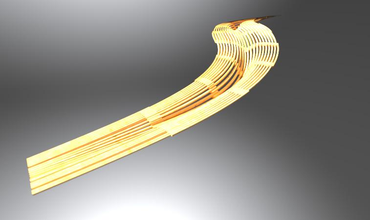
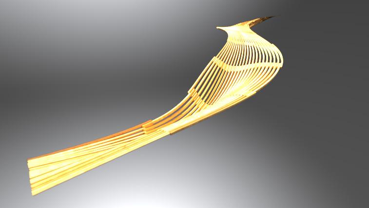
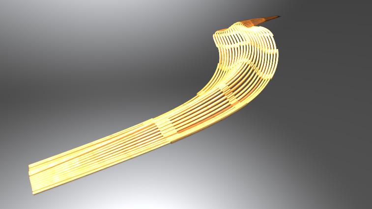
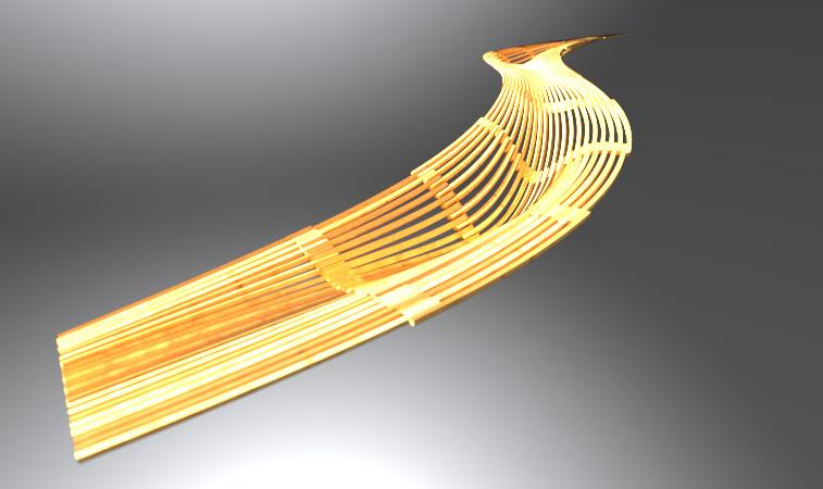
Surface geometry is understood and then created in order to inform the gently curved timber battens to form a series of simple beams that are interlocked in a staggered system with naturally increasing cross-sections at high stress areas.


15
displacement
4.79m to 4.80m 41.99m to 42.06m 4.80m to 4.82m 42.09m to 42.75m 4.79m to 4.79m 41.95m to 41.99m LENGTHS LENGTHS 4.82m to 4.87m 42.20m to 42.75m
timber battens
PARALLEL
Members: 220
Lengths: 4.78m to 4.80m

Members: 220
Lengths: 4.79m to 4.85m
Members: 220
Lengths: 4.78m to 4.81m
Members: 220
Lengths: 4.79m to 4.87m
Members: 220
Lengths: 4.78m to 4.83m
Members: 220 Lengths: 4.79m to 4.80m
Members: 220
Lengths: 4.78m to 4.85m
Members: 220
Lengths: 4.78m to 4.81m
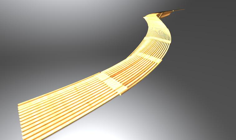
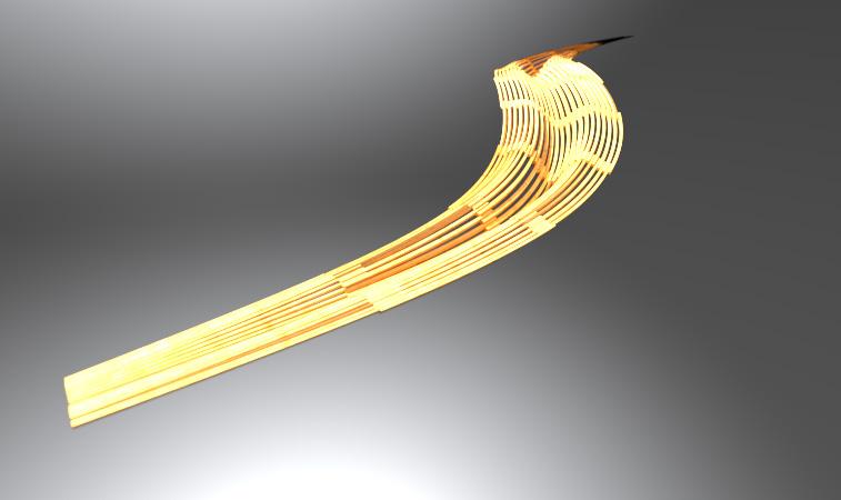
MEMBER DIFFERENTIATION ANALYSIS
Simple iterative study of beam members in surface driven design used to influence the choice of how geometry and curvature informs differentiation in beam length range.

16
2cm 6cm 3cm 8cm 5cm 1cm 7cm 3cm
structural shell
Area: 380m²
timber battens
Total members: 300
SHORT SPAN 6.6m
LONGER SPAN 17.0m
STAGGERING TIMBER BATTENS
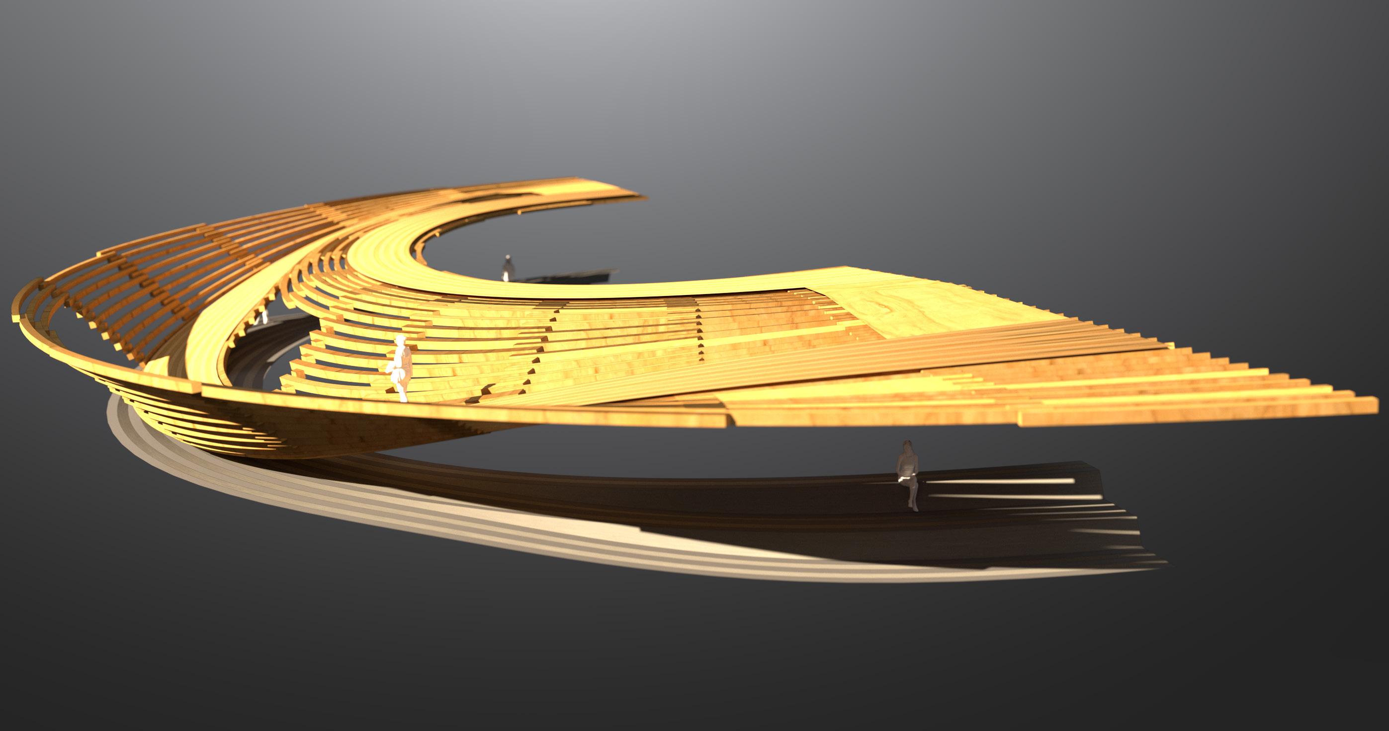
Using the staggering logic of interlocking each members by alternating each group of curves allows the continuity of a complex surface to be generated from simple members.
THINNEST BEAMS 13cm

THICKEST BEAMS 17cm
PLYWOOD SHEET 18mm
THROUGH BOLTS
LONGITUDINAL BOLTS
right view left view
17
SHELL HEIGHT 2.6m
exploded staggering
Total members: 98
CILL BEAM
DOWEL-JOINT
assembled staggering
Lengths: 3.54m to 5.44m
LONG ARM
SHORT ARM
DOOR OPENING
FUTTOCK SHELL ASSEMBLY
Fragment showcases the simple logic of staggering inter-stepping members to generate stiffness in a shell structure. The fragment showcases a spatial investigation of continuity for circulation inside.
PARALELL GRAIN
STAGGERING FRAMES
THINNEST BEAMS 13cm THICKEST BEAMS 17cm
STAGGER
2B FUTTOCK
1B FUTTOCK
2A FUTTOCK
1A FUTTOCK
18
staggered truss
Battens: 40
BEAMS 10x10cm
BEAM SPACING 30cm
TRUSS DEPTH 43cm
total length
Length: 74.3m
LONGITUDINAL BOLTS
SPACED SLATS
SEQUENTIAL STAGGERED DISTRIBUTION
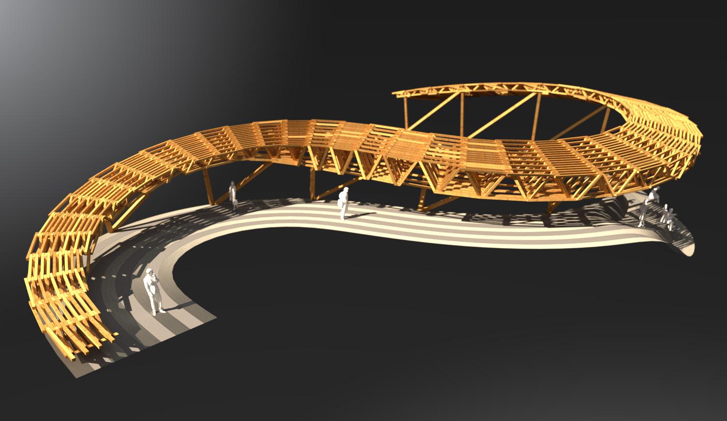
A complex assembly with simple straight members that increases its depth and width by stepping the members. Timber slats are staggered in a sequential pattern to cater for a truss system alongside the timber slats.
FLAT LAP JOINT
LONGITUDINAL BOLTS
TRUSS
SEQUENCE
SLAT 2
SLAT 1B
SLAT 3 SLAT 1A
19
STAGGERED SLAT
STAGGERED TRUSS
INCREASING TIMBER SLAT TRUSS
Timber slats in large scale complex roof with integrated trusses. The abstract roof fragment is made up of 1955 individual timber slats that primarily differ in the dimensions of the increasing length of the trusses at the wider cantilevers.
20
1.4m to 2.4m 2.4m to 2.8m 0.9m to 1.4m
LENGTHS
SHALLOW TRUSS 64cm
DEEP TRUSS 132cm
Members: 1955
timber slats
SHORTEST SLATS 1.8m
TRUSS WIDTH 260cm
TRUSS WIDTH 300cm
INCREASING TRUSS
DECREASING TRUSS perspective
LONGEST SLATS 2.6m
cross-sections
Battens: 10cm
Dowels: 1cm
kite dimensions
Length: 15.5m
Depths: 0.10 to 1.10m
PARALELL TRANSFER
THROUGH BOLTS
LONGITUDINAL BOLTS
NORWEGIAN GIRDER TECTONIC
In Norwegian heritage, traditional girders are more commonly understood as load bearing kites (i.e., “drager” norw.). Kites are often used in recipricol support to other beams. Kites transfers the load to adjacent structures such as columns, foundations, and walls.
DIAGRID
BATTEN 2B
BATTEN 2A
BATTEN 1B
BATTEN 1A
21
KITES (DRAGER)
NORW. TERM
RECIPRICOL JOINT
GIRDER DEPTH 10cm
DIAGRID 5.0x5.0m
exploded diagrid
Longituidnal: 71
Through bolts: 35
DIAGRID
BATTEN 2B
BATTEN 2A
BATTEN 1B
BATTEN 1A
diagrid-to-girder
GIRDER DEPTH 10cm
GIRDER SUPPORT 10cm
DIAGRID BATTEN ASSEMBLY
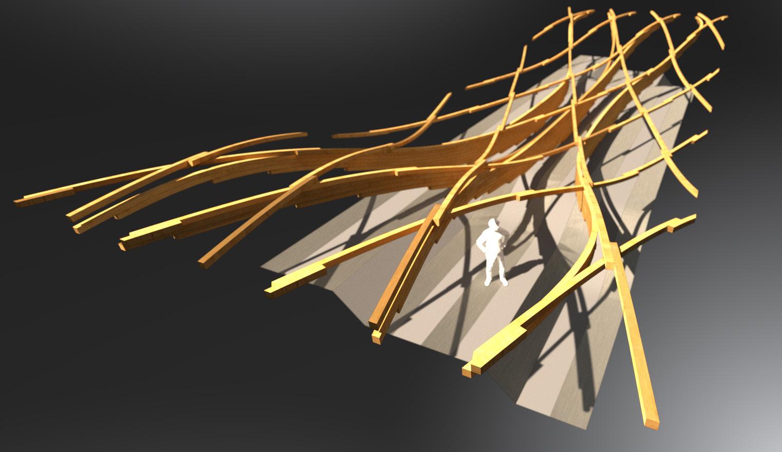
The girders allow the diagrid members to be segmented in a consistent length range throughout the member network. At the apex of the span, the depth of the diagrid battens require support from the girder, elsewhere they remain freeform.
22
timber batten diagrid
Lengths: 5.0x5.0m
diagrid members
Total members: 71
STANDARD BEAM 10cm
RECIPRICOL JOINT
BATTEN DIAGRID
DIAGRID-TO-GIRDER SYSTEM
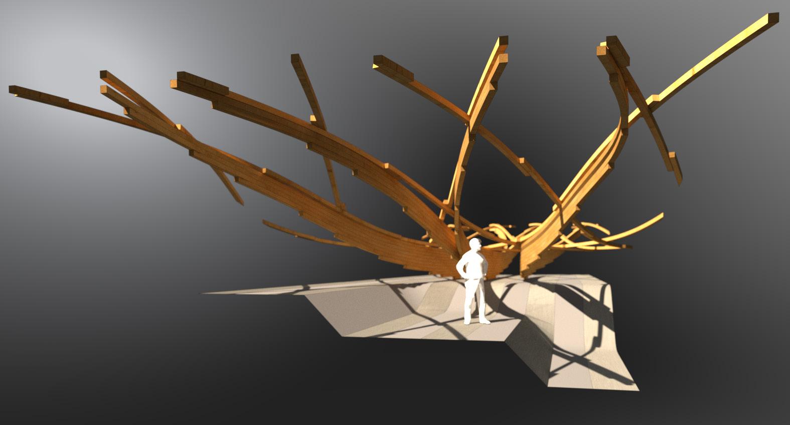
Longer spans and a different matrix acquires rethinking of the batten inter-stepping playfulness from the futtock construction. The long span kites withdraw from the rigid diagrid structure but returns at the apex of the span to join in to its polynomial points and support the staggering battens.
DIAGRID
KITES (DRAGER)
BATTEN 2B
BATTEN 2A
BATTEN 1B
BATTEN 1A
23
PARALELL TRANSFER
SHEAR SUPPORT LAP JOINT
left view
exploded lattice
Total members: 55
assembled lattice
Heights: 3.30 to 6.86m
LONGEST BEAM 10.8m
lattice dimensions
Lengths: 4.85 to 10.85m
Depths: 0.10 to 0.30m
TRAVERSAL LANE 1.40m
FORMAL SEATING 1.40m
INCREASING LAP-TO-SPAN
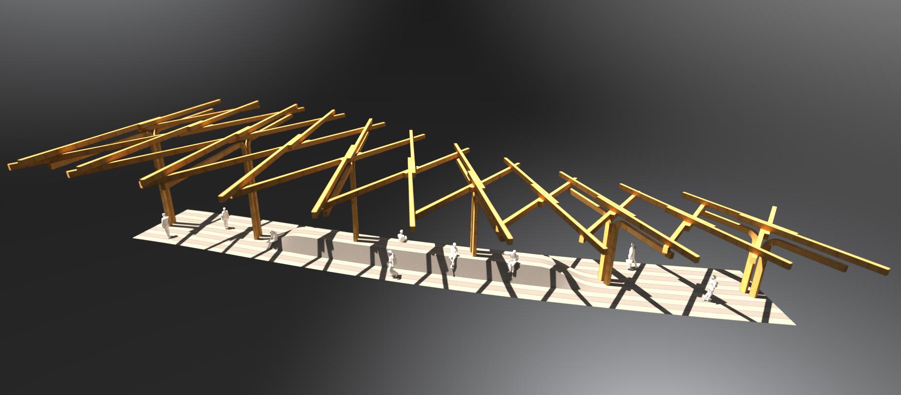
In this fragment a formal language is developed in order to test the flexibility of straight timber battens. As the height increases the member span and lap joint increases in length. Members are made straight and simple to allow flexibility for elements to rotate, extend and move within the diagrid.
LATTICE
COLUMN
LATTICE 2B
LATTICE 2A
LATTICE 1B
LATTICE 1A
24
LONG LAP JOINT 1.40m
SHORT LAP JOINT 2.60m
SHORTEST BEAM 6.0m
INCREMENTAL STEPPING MEMBERS
Tectonic study that looks in to the utilization of member lengths and the result of less curvature, in which ultimately allows the spawning of level differentiation. Material distribution thins out as the span increases, likewise the depth of each member thins out proportionally.
25
41.9m
40.8m stepping lamellae ≥2.2m ≥2.1m ≤38.8m 18.9m 18.4m ≤37.8m 13.6m to 16.9m 13.9m to 17.4m 19.9m to 28.8m 20.4m to 29.5m 2.1m to 11.0m 2.2m to 11.3m LENGTHS 31.8m to 37.8m 32.6m to 38.8m Total members: 14 Total members: 14 beam lengths LEVELS (+2.50m) LEVELS (+0.00m) HEIGHTS
Length:
Length:
26
1:100 prototype aeroply
ceiling heights
Heighest: 7.40m
Lowest: 3.65m
BOARD 22x103cm
BEAM 22x62cm
BATTEN 22x21cm
LAMELLA MATERIAL DISTRIBUTION
SHEAR SUPPORTS
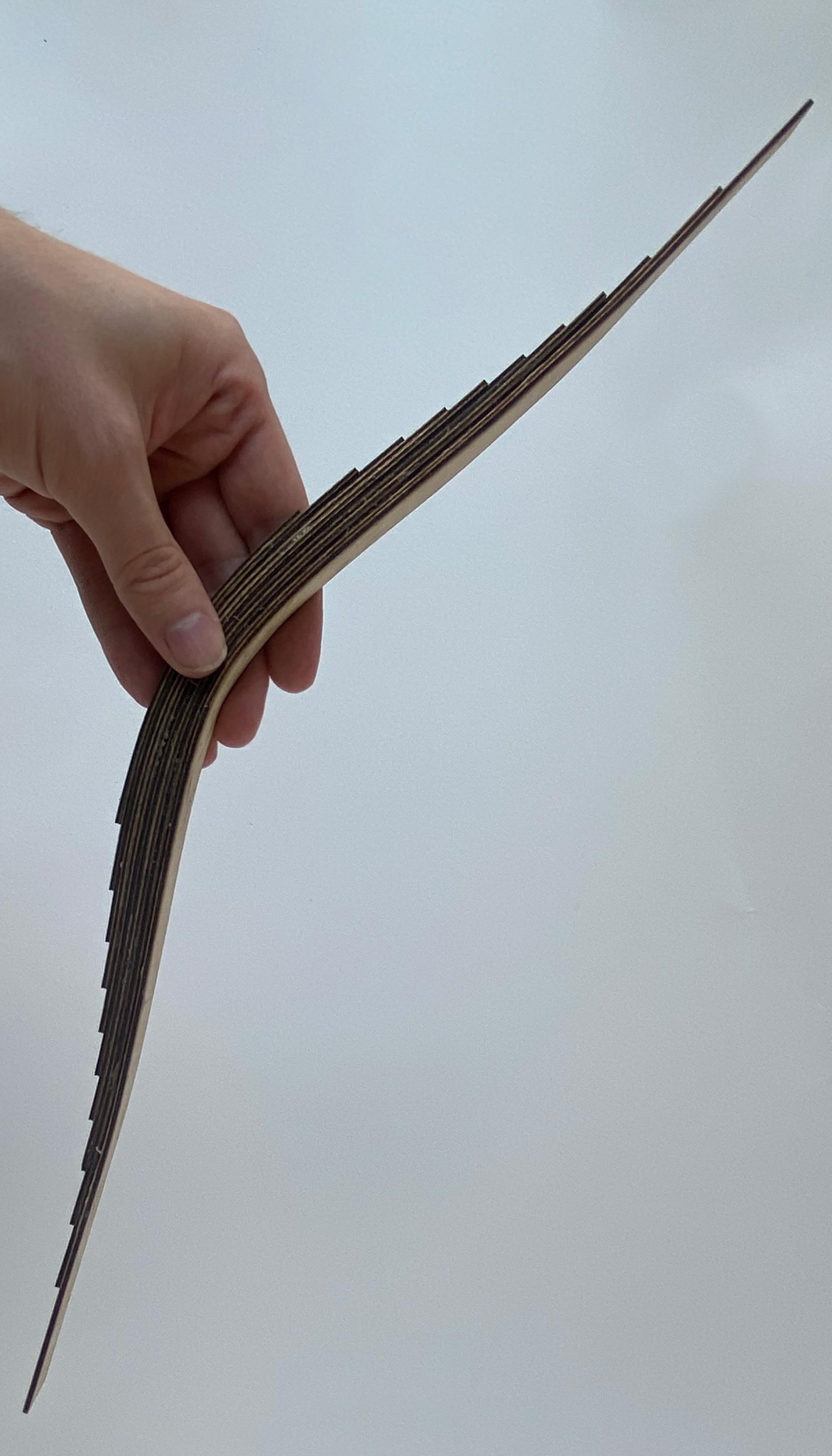
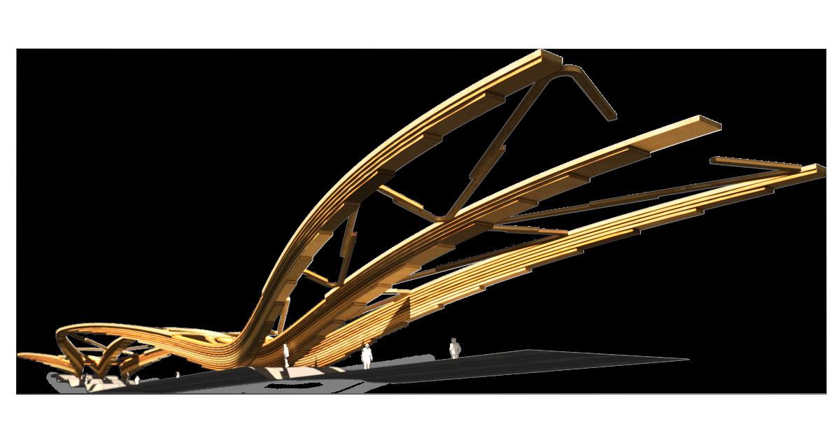
Early fragment of stepped and curved lamellae scaled according to a material distribution principal. The different lengths of the lamellae yield different curvature resulting in staggered span arches. The girders are equally braced by diagonals staggered but gluelaminated this time.
DECREASING DEPTH
INCREASING WIDTH
LENGTHS
2.1m to 11.0m
13.6m to 16.9m
19.9m to 28.8m
31.8m to 37.8m
27
GIRDER 22x103cm GIRDER 22x160cm
worm’s-eye view
girders
Length: 356m

Width: 20.4m
Shortest: 40.8m
STAGGERED SPAN ARCHES
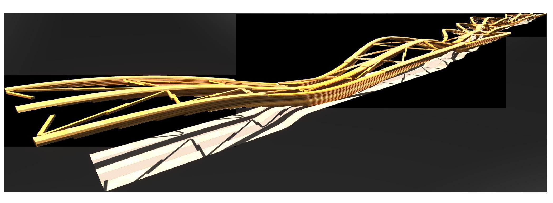
Large scale infrastructural fragment with staggered long span arches braced by staggered lamella diagonals. Spaces are generated from two components that were differentiated from the initial level study by discarding extreme curvatures in the lamellae.
29
front view
Longest: 61.2m span arcs
LOWER
END CONDITION 6 12
7 1 8 2 9 3 10 4 12 11 5 6
TRUSS BRACING TRI-SPAN 1 7 UPPER ARC STEPPED LANDING 5 11 LAP JOINT GROUND PLANE 3 9 KITES (GIRDER) SHORT SPAN 2 8
ARC
ABUTMENT LANDING LONG SPAN 4 10 LEGENDS
Member range
≥82.7m ≥82.7m
≤1.4m 26.9m
LAMELLA NETWORK MODULES
Modules: 6pc
Modules: 9pc
swing parallel hybrid 34.9m 28.3m
HEIGHTS
CENTER GIRDER (+0.40)
GROUND (+0.00m) GROUND (+0.00m)
Set of standardized parts or independent units that can be used to construct a more complex structures that subsequently can faciliate spaces in two directions. The staggered arches can be further sharpened and optimized through form-finding processes.
30
Modules: 8pc ≥82.7m ≤2.3m ≤1.4m
SYSTEM DIFFERENTIATION
Members are diversified by the usage of three-to-four modules to allow flexibility in multiple directions. The lamellae are free to join in at specific node connections to bifuricate or yield recipricol support to the connection.
31
swing parallel varied height SHEAR PLATE (+0.40m) L 00 (+0.00m) L 00 (+0.00m) L 00 (+0.00m) L -01 (-4.50m) HEIGHTS PLANK 22x295cm BOARD 22x216cm BEAM 22x115cm JOISTS 22x144cm BEAM 22x108cm 15.5m to 28.3m 28.4m to 47.7m 1.4m to 15.3m 47.7m to 83.1m
AKERSHUS FORTRESS
A NEW MARINA FOR
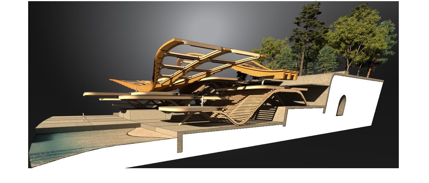
32
Ferry Terminal At The Waterfront Of Oslo Block-Laminated Beams In A Composite Material System
OSLO
H
TRAM LINES OSLO
LINE 19
LINE 18
LINE 17
LINE 13
LINE 12
LINE 11
MAP INFOGRAPHIC
LARGE INTERCHANGE
SMALL INTERCHANGE
HIGH FREQUENCY CITY BUS LINE INTERCHANGE
STOP IN DIRECTION OF ARROW ONLY
OSLO TRAM LINE NETWORK
Oslo Tram is a 39,6 km tram network, with 6 lines and 99 stops. Oslo Tram was formed in 2003 and is responsible for the management of tramway operation in Oslo. The map shows the the most densified tram lines by line thickness.
33
TRAM REPORTS 2011
TRAM PROJECTS DONE 2000-2010
PLANNED TRAM PROJECTS 2011-2014
CURRENT TRAM LINE
REGISTERED RAIL UPGRADES
RAIL WEAR, RESULTS WEAR MEASUREMENT 2010
TRACK GAUGE ERROR, RESULTS AUTUMN 2010
RAIL DAMAGE, AUG-OCT 2010
FJORD-LINE INTERCHANGE
H HIGH FREQUENCY INTERCHANGE
OSLO PORT LINE
Analysis of Oslo’s tram line network development and the urge to ease the commute intensity from west-to-east Oslo. The proposed fjord city shifts the center of gravity toward the seafront. Former transport and port areas will be replaced by city, park and important destinations.
35
OSLO PORT LINE CLOSED IN 1983
FJORD CITY
PROMENADE
ATTRACTION
RECREATIONAL

AKERSHUS FORTRESS
FJORD INTERFACE


POINT OF INTEREST
FJORD CITY OSLO
Fjord City is a project issued by the muncipality of Oslo that aims to free up the current inactive areas towards the sea and use these for future-oriented urban development with housing, recreation and public amenities in such a way that the city opens up towards the fjord.
37
PIPERVIKA
AKERSHUS PIER
PIPERVIKA
TYPOLOGIES
WHOLE SALE MARKET
MIXED USE
FOOD SERVICES
FERRY TERMINAL
PIER
WHARF
BUILDING CODE
BUILDING PROTECTED UNDER CULTURAL HERITAGE ACT - § 22A
PROTECTED THROUGH OWN REGULATIONS
AREA PROTECTED UNDER CULTURAL HERITAGE ACT - § 22A
AREA PROTECTED UNDER CULTURAL HERITAGE ACT - § 6
AFFECTED PROPERTY OF THE NATIONAL PROPERTY BOARD
AFFECTED PROPERTIES
AKERSHUS
VIPPETANGEN PIER 3
OSLO FERRY TERMINAL
FORTRESS / VIPPETANGEN PENINSULA
The peninsula was previously the location of a military facility and of a stone quarry, as well as military and civilian baths. Vippetangen has always been an important transport hub, and remains the main port for passenger ferries in Oslo.
38
AL OSLO FISHING HALL
AKERSHUS PIER
vippetangen
AKERSHUS PIER
TYPOLOGIES
WHOLE SALE MARKET
MIXED USE PIER
FOOD SERVICES WHARF
SHED 32
SHED 31 SHED 34
SHED 33
scale and dimension
OSLO CRUISE TERMINAL
AKERSHUS FORTRESS / VIPPETANGEN PENINSULA
Vippetangen is the southern tip of the Akersnes peninsula in central Oslo, Norway, located southeast of Akershus Fortress looking out in to the Oslofjord. It has in the past served as an important part of the port of Oslo. The area is currently undergoing urban renewal as part of the Fjord City development.
39
AKERSHUS FORTRESS
AKERSHUS FORTRESS
PIPERVIKA
AL OSLO FISHING HALL
OSLO GRAIN SILO
OSLO FERRY TERMINAL
TUNNEL
parallel arcs 1
Surfaces: 54
varied arcs 2
Surfaces: 42
docks
quay arcs
GLOBAL MASSING ITERATION 1
Simple shells are generated in Karamba3d iexploring the ideal arc massing for the site. Various attempts are made to address current access points and new quays for the transport hub.
40
OSLO PORT LINE NEW TRAM LINE
GLOBAL MASSING ITERATION 2
The massing models are designed around the arc height and span limitations from Karamba3d and also the integration of the Oslo Port Line and the Akershus Fortress context.
41
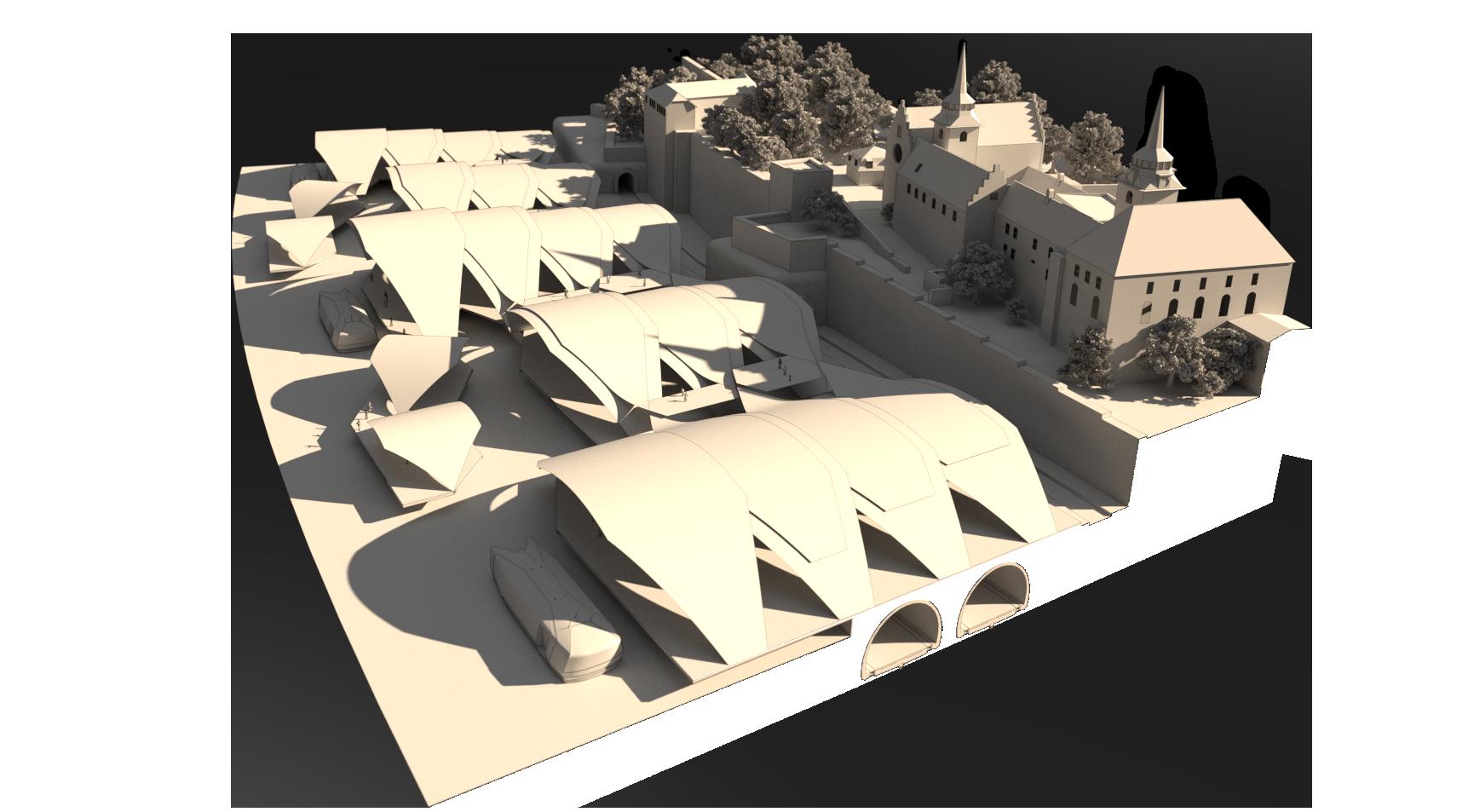
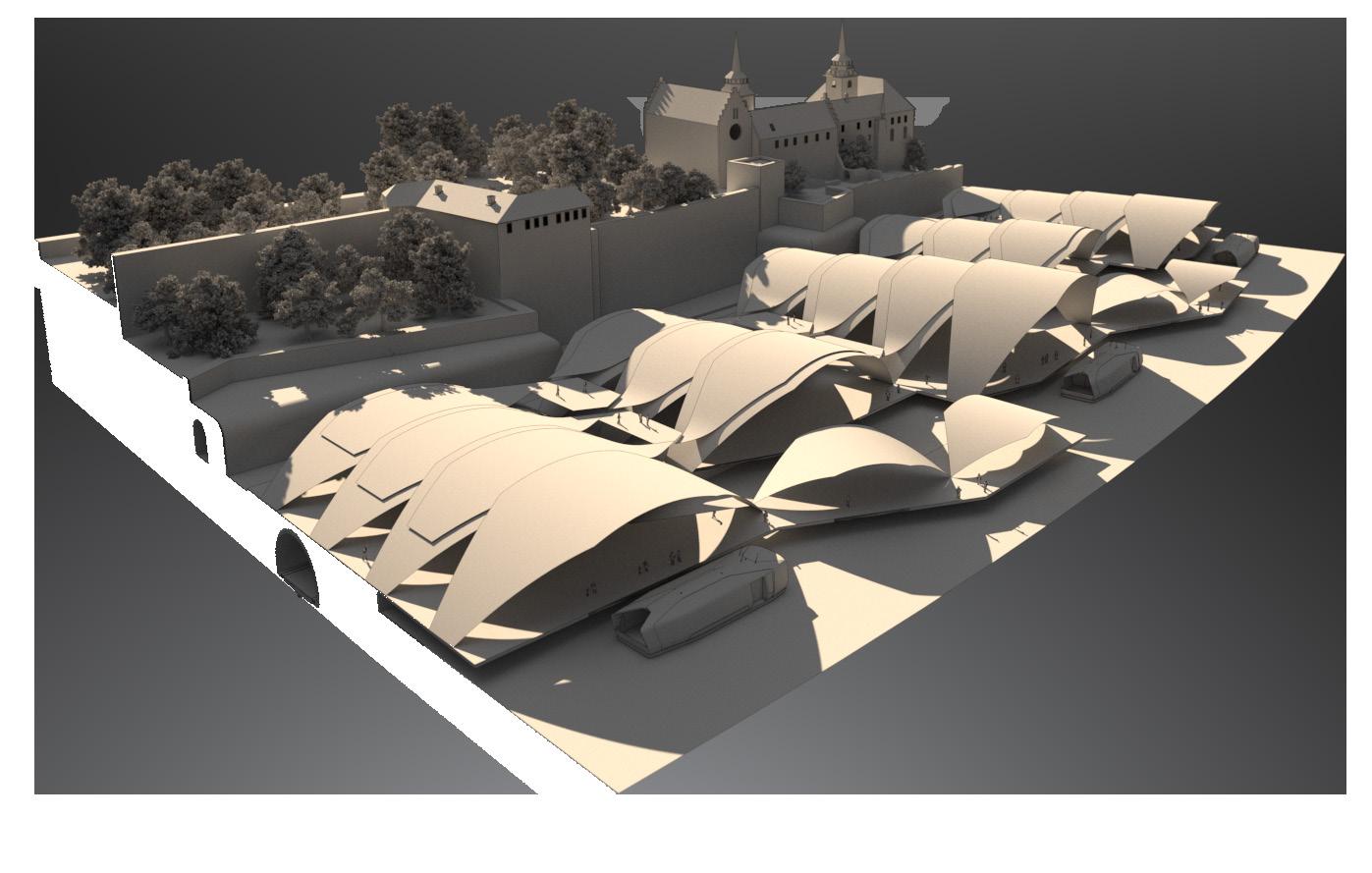
Area: 21 221m2 total area ≤155m2 458m2 ≥641m2 Area: 18 947m2 total area ≤163m2 511m2 ≥818m2
FERRY TERMINAL DEVELOPMENT
Formalizing the geometries to surfaces and planes allows the flexibility of changing and adjusting relationships happening in the array of shell-like-structures. Additionally, generating a system from key control points of a set of parallel running NURBS curves from structural software plugin Karamba3D.
42
PORT LINE (+0.00m)
FERRY DOCK (-1.00m)
OSLO FJORD
PLATEAUS (+6.25m)
ROOF OVERHANG SHELL GRID LANDING
SHELL STEPPING
AKERSHUS FORTRESS
simple beam analysis
inverse bending moment
cross-sections generated
parallel lamellae
grain continuity
SIMPLE BEAM ANALYSIS
A simple structural analysis of the glue-laminated beam as a stick model is generated in order to optimize the arc shape further. Cross-sections are equally generated to develop a more efficient changing cross-section throughout the individual beam spanning across.
43
≤3.7m 15.9m ≥30.2m
VIENNA NASCHMARKT
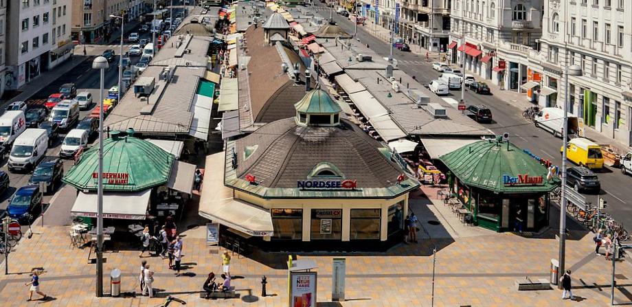
Vienna Naschmarkt has been around since the 16th century and offeres a wide range both Viennese and foreign products. The marketplace is an array of three rows of various stall columns over a 1.5 kilometres long stretch.
44
vienna naschmarkt
MARKETPLACE (+1.20m)
TYPOLOGIES
STALLS
DOCKING STORAGE
WHOLESALE
RETAIL
SERVICES
clipping plane
+1.75 meters
TO: PARKING LEVEL
TO: AKERSHUS F.
ACCESSIBILITY
FERRY TERMINAL
MARINA
MARKETPLACE
PROMENADE
TRAM-LINE
MARINA MARKETPLACE DEVELOPMENT 1
The urban landscape was informed by both the current Viennese Naschmarkt’s row and column layout and the traditional marked’s temporary parasol stalls that allowed for flexibility. The scheme is a combination of a set of modules that array, mirror and flatten to cater toward different access points.
45
wholesale market
perspective view
PLATEAUS (+3.00m)
PIER (+3.00m)
MAIN ENTRY TO: VIKING MUSEUM
TYPOLOGIES ACCESSIBILITY
FOOD SERVICES RETAIL MARINA FERRY TERMINAL PUBLIC AMENITY MARKETPLACE WHOLESALE LEISURE PROMENADE
MARINA MARKETPLACE DEVELOPMENT 2
46
wholesale market +1.80 meters perspective view clipping plane LOADING DOCK (+0.00m) LOUNGE BAR (+0.20m) PLATEAUS
The marketplace is defined a by a central radial reference point that divides the scheme into plots, however the grid is arranged orthogonal. Staircases and swept landscape is repeated and processed with planar flat slabs that are made for multi-purpose use in the new harbour side. UPPER LEVEL
(+3.60m)
(+4.00m) MAIN ENTRY FERRY TICKET BOOTH SEATING TRAM-LINE STOP TRAM-LINE
LOADING DOCK (-0.20m)
PIER ROOF (+5.00m)
FERRY PIER WATERFRONT
WHOLESALE (+6.00m)
MARINA MARKETPLACE DEVELOPMENT 3
The marketplace is defined a by a central radial reference point that divides the scheme into plots, however the grid is arranged orthogonal. Staircases and swept landscape is repeated and processed with planar flat slabs that are made for multi-purpose use in the new harbour side.
TYPOLOGIES
FOOD SERVICES
RETAIL
PUBLIC AMENITY
ACCESSIBILITY
DROP-OFF
MARINA
LEISURE PROMENADE perspective view clipping plane
MARKETPLACE
47
WHOLESALE wholesale market +4.00 meters
LAMELLA (+14.00m)
VISTA PLATAEUS (+4.00m)
TRAM-LINE STOP
TRAM-LINE
FJORD CITY MASSING
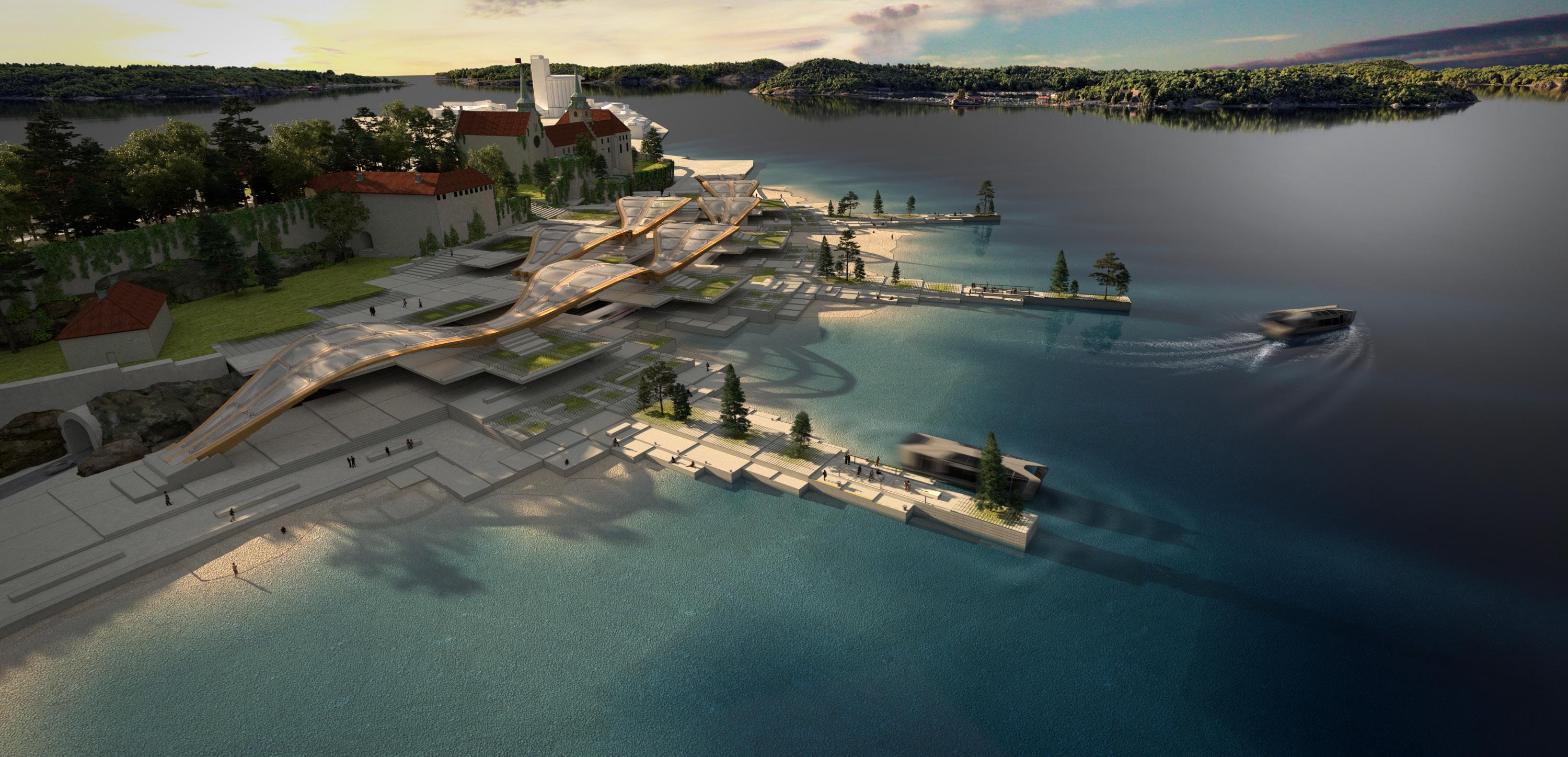
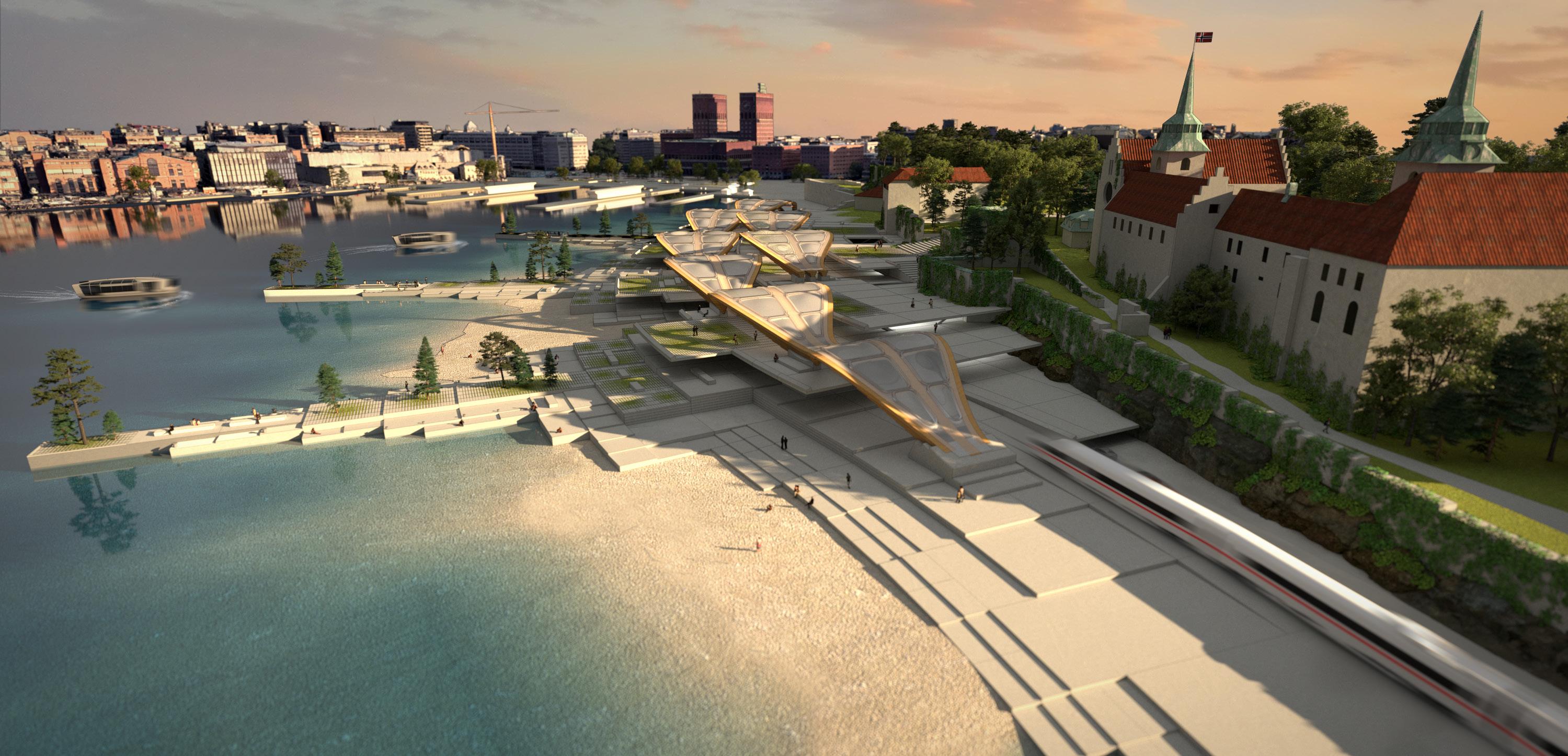
Overall strategy for Fjord City with two fjords or coves where the program is split between transport and leisure. The stepping plateaus activate the site with new access points of interest to the Akershus Fortress.
49 TYPOLOGIES RECREATIONAL RETAIL LEISURE PUBLIC AMENITY EVENT SPACE RESTURANTS OSLO TOWN HALL 1 LEISURE HUB 5 A.F. ACCESS 3 A.F. LOWER ACCESS 2 WHARF ACCESS 6 TRANSPORT HUB 4 LEGENDS 1 6 5 4 3 2
DEVELOPING SINGLE-CURVED TYPOLOGIES
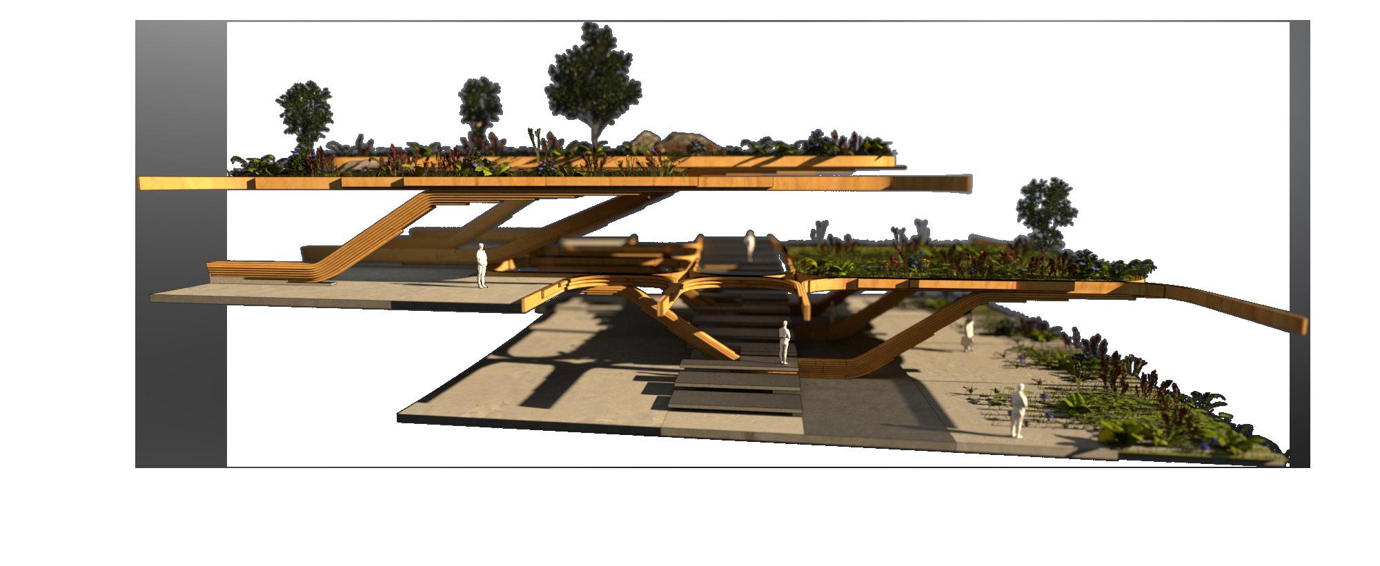
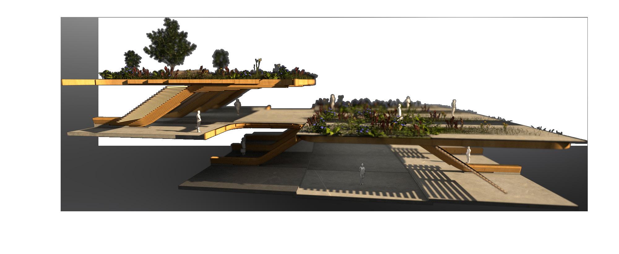
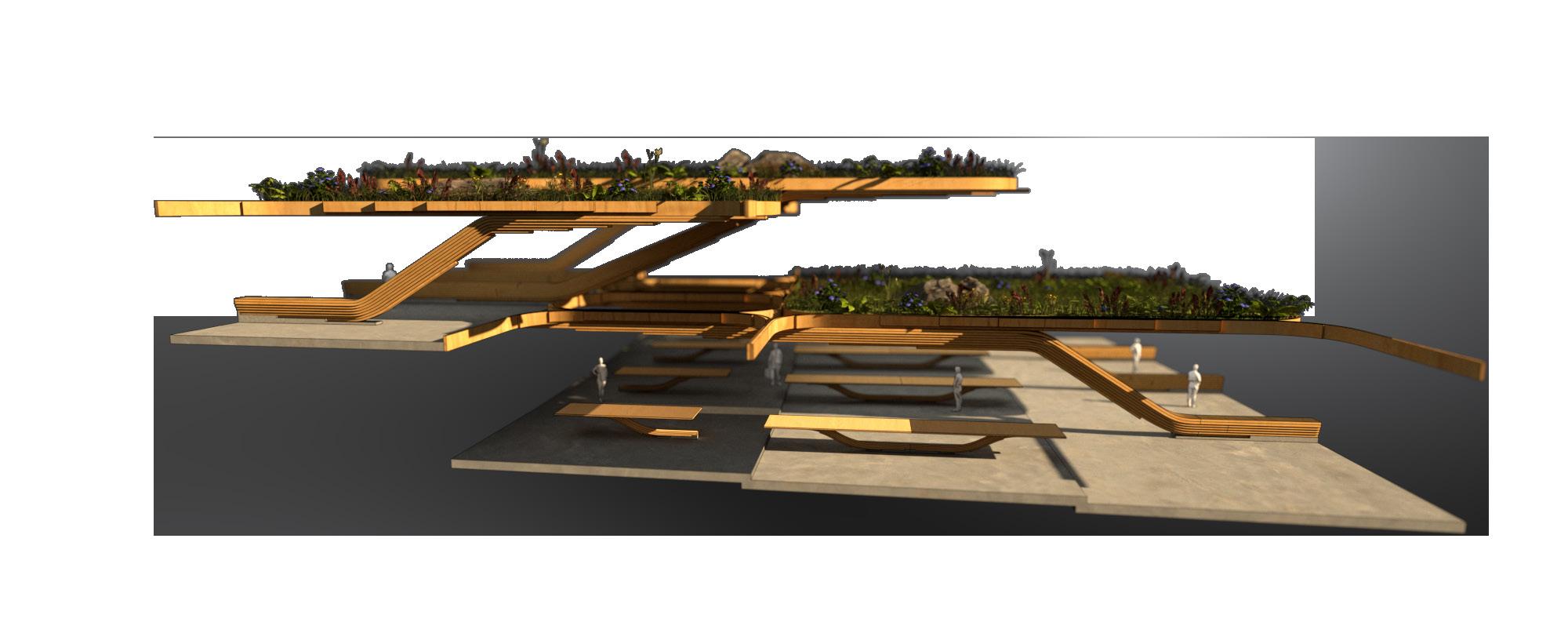
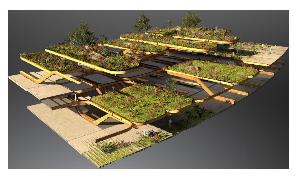
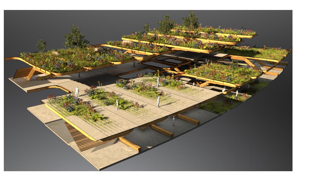
Different spatial typologies are developed for mixed-use purposes. All space are designed planarly and avoids any double curvature and can be flexibly configured to cater different programs.
50
workshop auction hall offices
mezzaine akvavit bar norw. saeter
retail promenade recreational space open air space
mezzaine space staircase integrated
staircase integrated
retail promenade recreational space
TYPOLOGY MIXED USE
staircase integrated
retail promenade recreational space
51
Single-curved typologies are configured around a radial plan that steps creating terraces. Timber is used in a single curvature using the block lamination technique in response to formalize the terracing of project.
Sorting tapered profile by rounding of widths to specified factors
Sorting hierarchy tool
DOMAIN START DOMAIN END
SPECIFIED CROSS SECTIONS
NUMERIC SORTING TOOL
Cross sections are informed by specifying the top and bottom dimensions to generate a consistent tapering profile. Number of profiles is also specified, by which dictates the stepping consistency. The intermediate dimensions that are generated within the domain, can easily be adjusted to standard widths. This method can be combined with rounding the numbers to specify predictable dimensions.
52
Sorting in C24 timber strength grade application
C24 75mm
6x3” 75 x 150mm
7x3” 75 x 175mm
8x3” 75 x 200mm
4x3” 75 x 100mm 9x3” 75 x 225mm
Rounding off amount of profiles involved in matrix
5x2” 47 x 125mm
6x2” 47 x 150mm
7x2” 47 x 175mm
8x2” 47 x 200mm
9x2” 47 x 225mm
Generating outputs from tables of different timber stock dimensions
C24 47mm C24 47mm
2x2” 47 x 50mm
3x2” 47 x 75mm
47 x 100mm
5x2” 47 x 125mm
6x2” 47 x 150mm
7x2” 47 x 175mm
8x2” 47 x 200mm
BLOCK LAMINATION SORTING TOOL
Cross sections are measured in domains that are representative of industry standard categories. From the created pool of dimensions, cross sections can also be manually adjusted and controlled in the list structure.
53
4x2”
Sorting in C24 timber strength grade application
Rounding off amount of profiles involved in matrix
Generating outputs from tables of different timber stock dimensions
AUTOMATED SORTING PROCESS
Material information on available dimensions within the Norwegian C24 grade timber table is sorted using stock dimensions in two different ranges: 47mm and 75mm. The block groups stacks are created by plotting the available dimensions from the chart and specifying the profile quantity. In this way, dimensions remain consistent within a referenced chart.
54
8x3” 75 x 200mm 4x3” 75 x 100mm 4x3” 75 x 100mm 9x3” 75 x 225mm 7x3” 75 x 175mm 7x3” 75 x 175mm 6x3” 75 x 150mm 6x3” 75 x 150mm C24 75mm C24 75mm 5x2” 47 x 125mm 2x2” 47 x 50mm 6x2” 47 x 150mm 7x2” 47 x 175mm 8x2” 47 x 200mm 9x2” 47 x 225mm 4x2” 47 x 100mm 3x2” 47 x 75mm C24 47mm
stepping plateaus
INFORMAL TERRACES
MARINA PROMENADE INTERNAL PROMENADE
BEACH CONDITION
TRANSPORT ZONE
WATER TAXI ACCESS
RECREATIONAL ZONE
SITE DEVELOPMENT 1
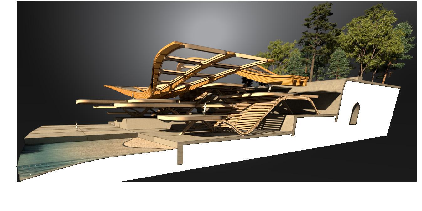
Project re-investigates the potential to step and interact with the boundary conditions of the Akershus Fortress retaining wall. Terraces are stepping down, creating programmatic and level differentiation.
STEPPING LANDSCAPE
TYPOLOGIES
RESTURANTS
RECREATIONAL
EVENT SPACE
RETAIL
55
OSLO PORT LINE
FORMAL TERRACES
TRANSPORT ZONE
WATER TAXI ACCESS
RECREATIONAL ZONE
FJORD CONDITION
WHOLESALE MARKET
RETAIL PROMENADE
SITE DEVELOPMENT 2
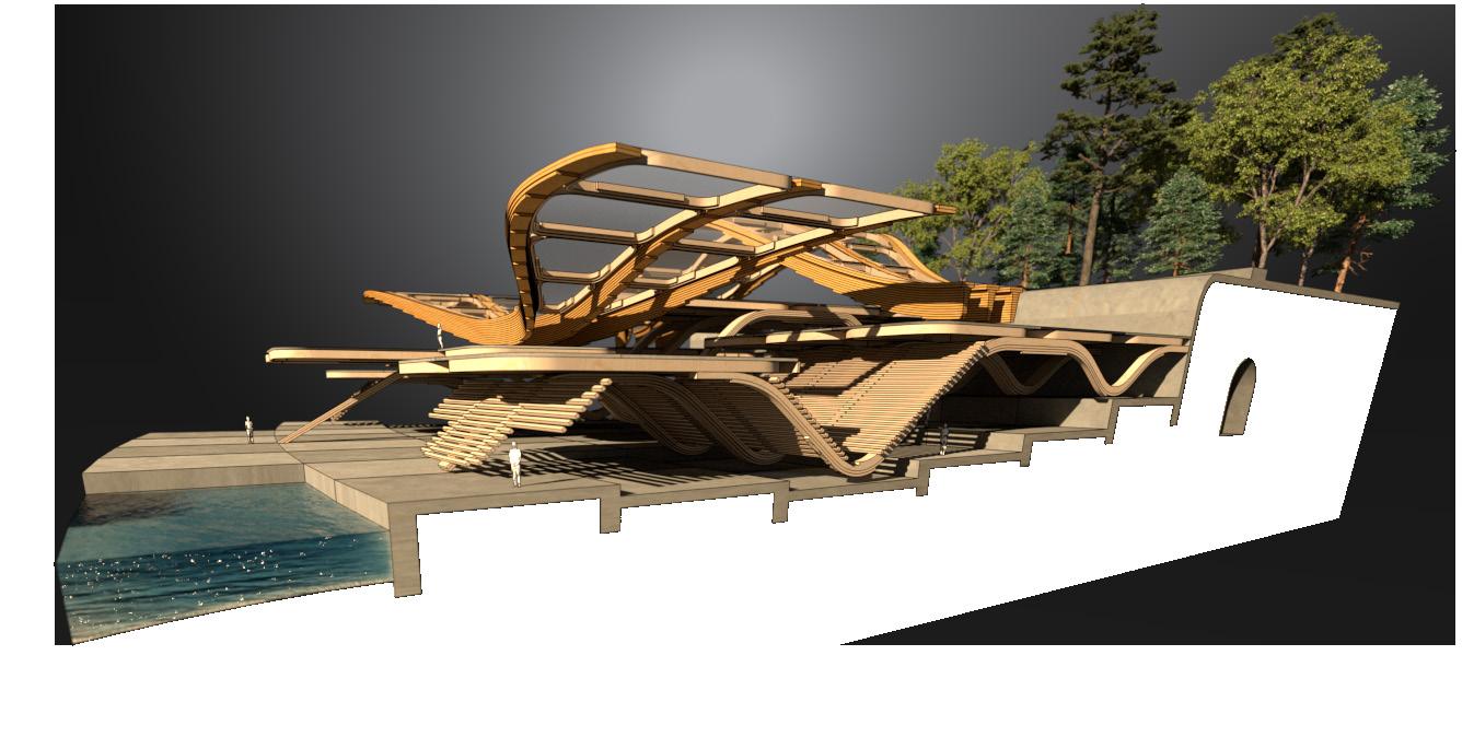
Further development highlights the contraints of the timber terraces, shifting the attention to formalize the terraces stepping down to the fjord and rethinking material options.
FORTRESS ACCESS
TYPOLOGIES
RESTURANTS
EVENT SPACE stepping plateaus
56
RECREATIONAL RETAIL
spatial fragment
ROOF OVERHANG
TRANSPARENT FILM
ABUTMENT CONDITION
roof girders
EVENT SPACE
RESTURANT TERRACE
RECREATIONAL
TERRACE DEVELOPMENT
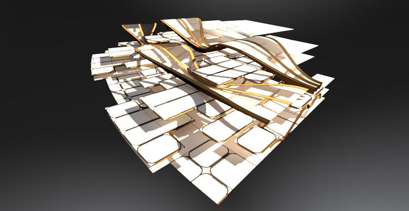
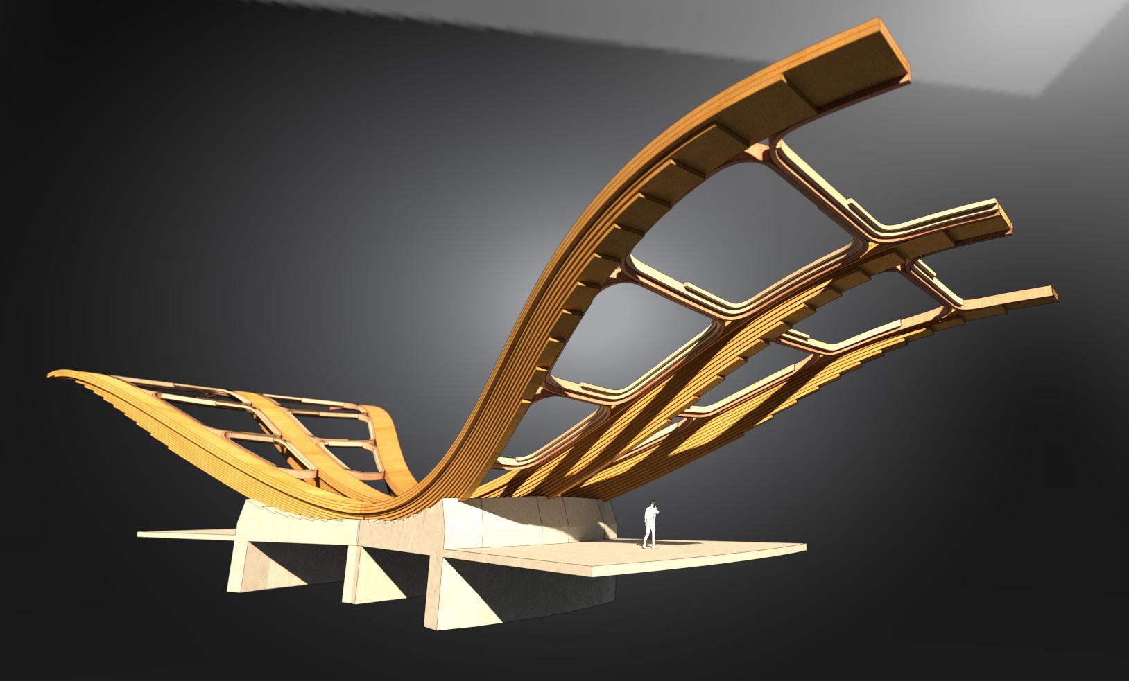
Development of timber terraces integrated with roof structure. Fragment explains the relationship of the two different modules to the girders acting inversely, and also connecting the wharf to the Akershus Fortress.

57
ROOF BRACING
ROOF DOME LIGHT
double tri-span
PROFILE THINNING
PROFILE THICKENING
STEPPED LAP JOINT
GROUND LEVEL
single tri-span
SECONDARY STRUCTURE
FLAT FLANGE EDGE
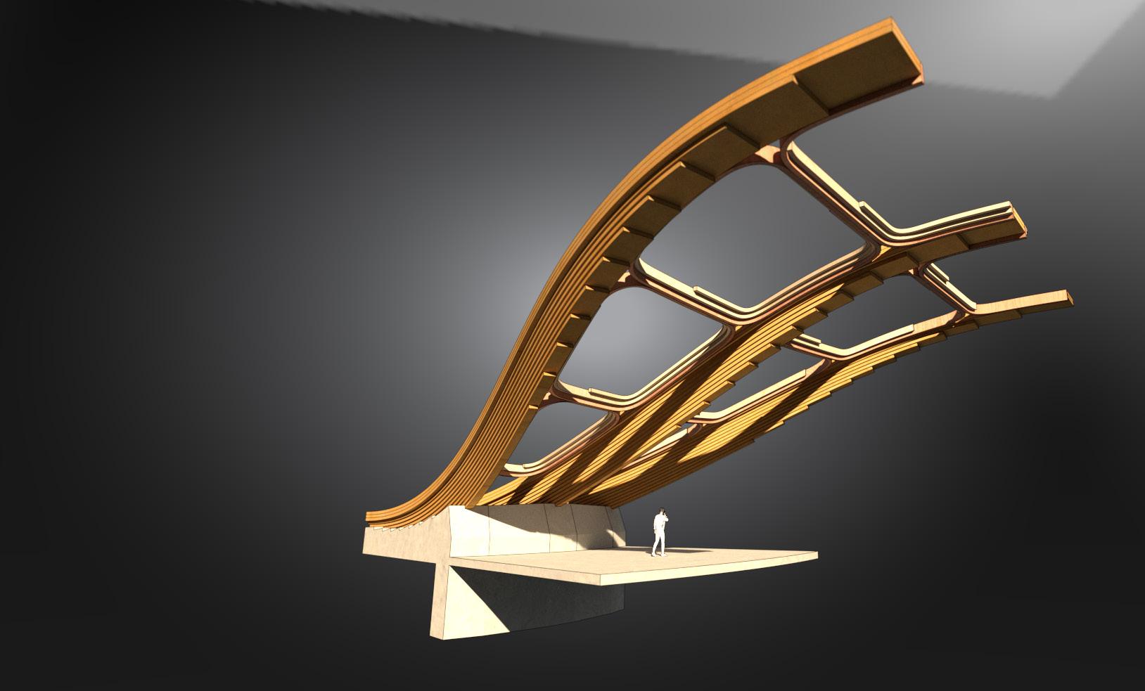
ABUTMENT LOAD TRANSFER
ABUTMENT DESIGN
58
Principal design of the arch springing from foundation and delaminating the material layers. The horizontal thrust is taken directly by the abutment and a tie rod in the slab.
RECESSED HOLES
THREADED RODS
WASHER & NUT
SINGLE STEPPED LAP
DOUBLE STEPPED LAP
ASSEMBLY LENGTHS
The girders may be conveniently transported in segments on pull-out trailers, with the parent struCtures being installed first, followed by the patch girders at the construction site. For ease of transportation, the facility is also accessible by sea, where larger shipments may be made.
LANDING GIRDER
SECOND GIRDER
59
REINFORCEMENT LAYER
PATCH
FIBER ORIENTATION
STEPPED LAP JOINT
STEPPED LAP WIDTH
DOUBLE STEPPED LAP
JOINT LOCATED AT MOMENT ZEROLINE
RECESSED WEATHER PROTECTION HOLES
STEPPED LAP JOINT
THREADED RODS
WASHER & NUT
PATCH GIRDER
PARENT STRUCTURE
STEPPED LAP-JOINT
Lorem ipsum dolor sit amet, consectetur adipiscing elit. Duis at volutpat ex. Morbi quis egestas elit. Morbi sit amet imperdiet turpis. Etiam pulvinar, sem at vehicula pellentesque, justo nisl aliquam erat, id gravida massa felis vitae sem. Nullam commodo velit vitae tortor scelerisque, nec malesuada odio aliquam.
60
PROGRAMME AND TERRACES
Abutment design and terraces are designed together to inform and address the programme and structural logic of the loads needed to transfer as the scheme increases in levels.
61
TIE ROD PLATE PILLAR TRANSFER WINDOW SUPPORT clipping
PROGRAM
SPACE +1.75 meters clipping
plane RESTURANTS/RETAIL PROMENADE/LEISURE
EVENT
plane
WEATHER PROTECTION PROFILE
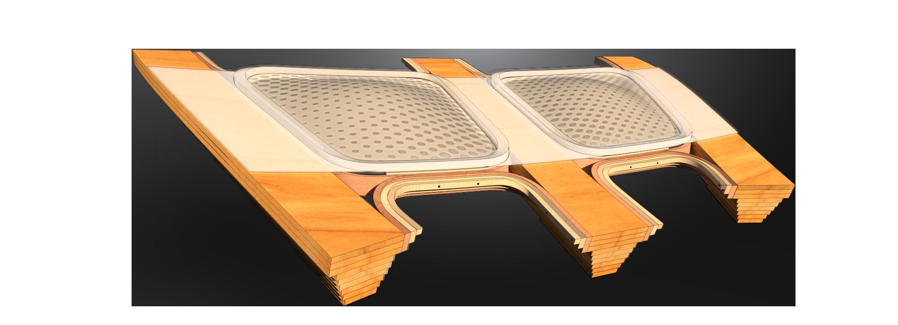
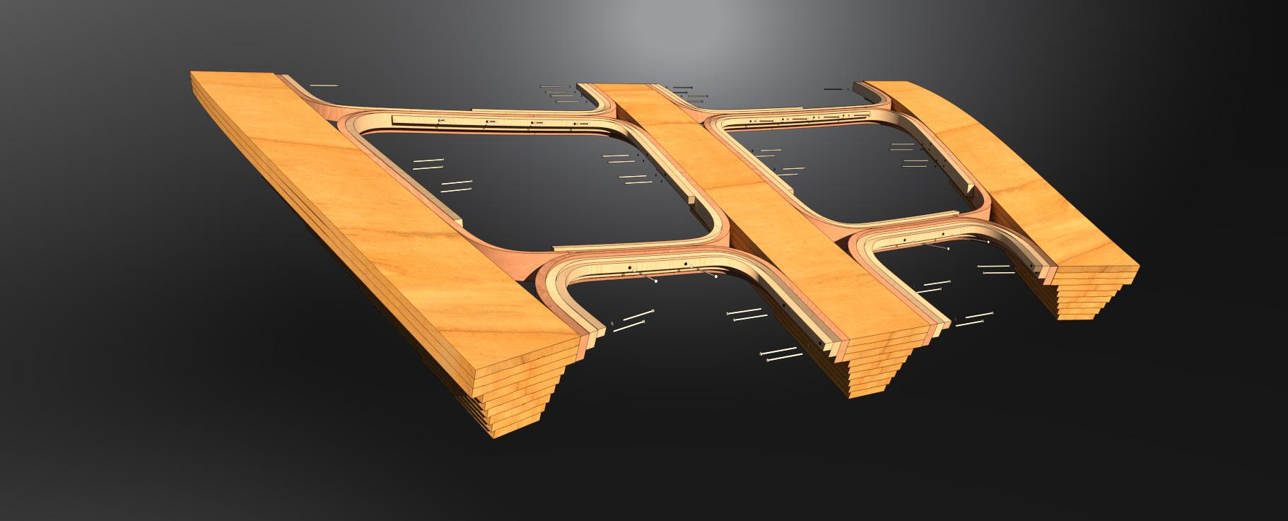
The wicking angle for the glulam girders was tested and controlled with the addition of a water shedding angle control. The top flange of the glulam girder profile, by which is used as a perpendicular landing for the curved batten bearings to be dowelled to, achieves the passive water protection angle.
62
EXPOSED SURFACE EXPOSED SURFACE 26.7° - 23.0° 38.8° - 30.0° WICKING ANGLES FLANGE
1 WICKING
3 GIRDER
2 LEGENDS 2 1 3
DETAIL
ANGLE
RIDGE
RECESSED HOLES
THREADED RODS
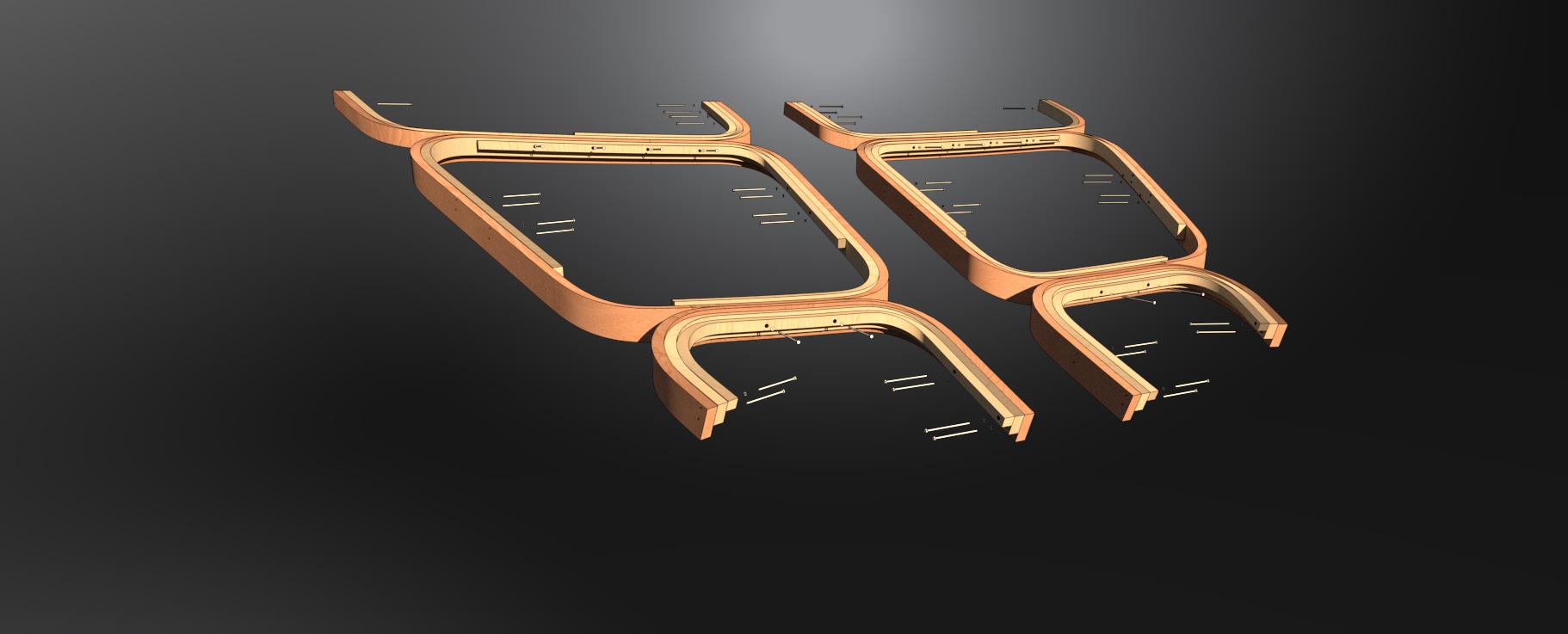
WASHER & NUT
GIRDER
T-PROFILE FLANGE
ETFE FILM
ETFE FOIL CUSHIONS
ROOF BUILD-OUT COMPOSITE
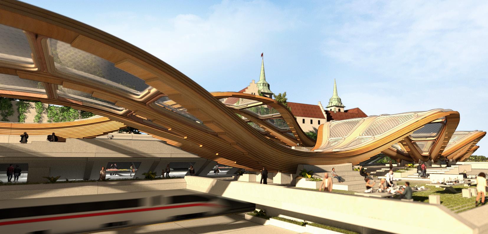
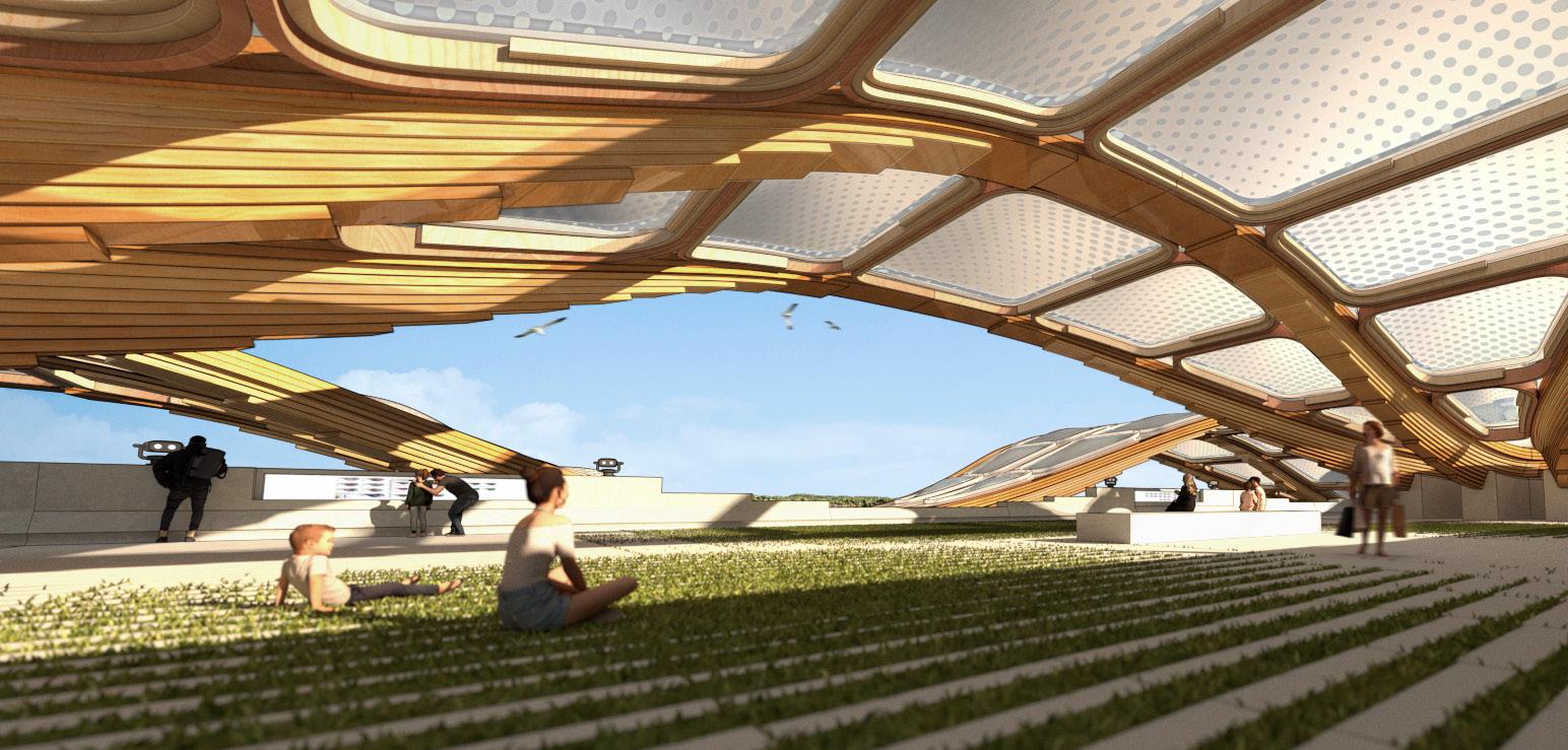
The girders are braced with single curved stepped profiles to address the lateral stiffness in the arcs. An ETFE (Ethylene tetrafluoroethylene) membrane is laid on top of the roof alongside ETFE foil cushions that is inflated to create dome skylights for spaces below.
TIMBER BRACING
STEPPED LAMELLAE
63
AKERSHUS FORTRESS DEVELOPMENT
Programmatic cross section development of the Akerhus Fortress, where the terraces are of the same material and consistency as the current retaining wall. The access point from the quay to the fortress is enabled by opening up the fortress wall.

65
FORTRESS ACCESS
TYPOLOGIES RECREATIONAL RETAIL LEISURE EVENT SPACE RESTURANTS WHOLESALE MARKET 1 LEISURE ACTIVITIES 5 INTERNAL STREET 3 TRAM-LINE STOP 2 FJORD QUAY 6 AKVAVIT BAR 4 LEGENDS 5 6 4 1 2 3
LEISURE ACTIVITIES MARINA PROMENADE RESTURANTS MEZZAINE AKVAVIT BAR RETAIL PROMENADE INTERNAL STREET TRAM-TRAIN PLATFORM
QUAYS TRANSPORT HUB WATER TAXI
SITE PLAN







66
OSLO PORT LINE TRAM-LINE STOP 1 7 A.F. ENTRANCE EVENT SPACES 5 11 TRANSPORT HUB A.F. MAIN GATE 3 9 WATER TAXI URBAN FJORD 2 8 PARK CAR LANE 6 12 MARKET ENTRANCE AKVAVIT BAR 4 10 LEGENDS 1 2 3 6 7 5 9 4 8 10 12 11
Closer view of Fjord City integrated with the Akershus Fortress and Oslo Fjord.






SECTIONAL FORTRESS OVERVIEW
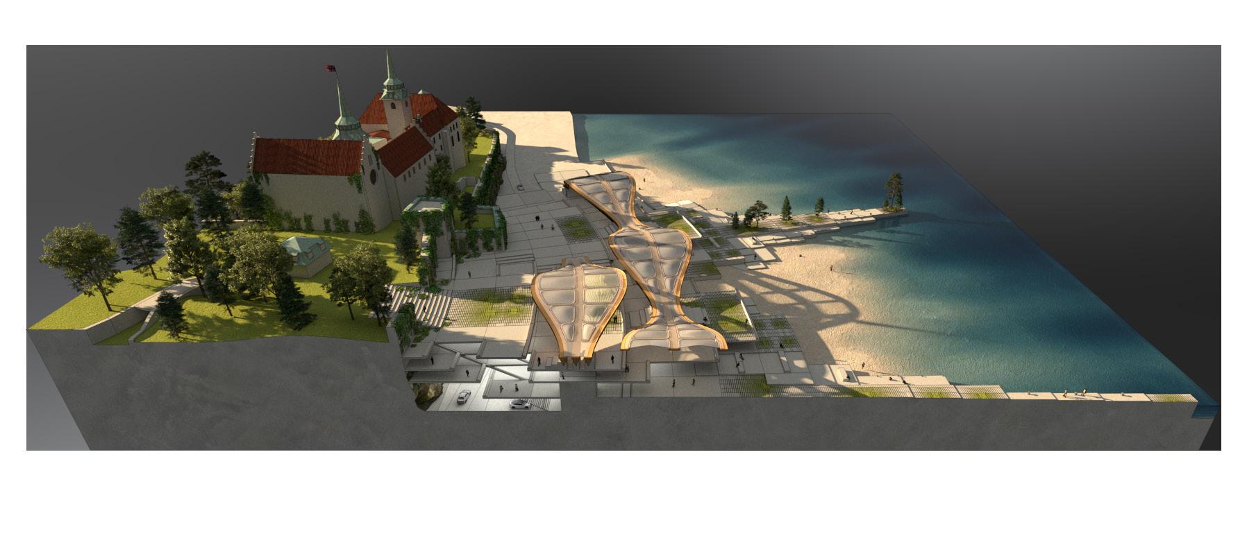
The diagram shows the new connectivity to the city and the previous access points. Program and layout overview of Fjord City and its layering. The inaugrated spaces are embedded in the plinth allowing the double-durved glulam to be free of curtain walls and insulation.
68 3 4 5 2 1 7 6 CITY ACCESS 1 7 OSLO PORT LINE FOYER 5 11 AKERSHUS BEACH OFFICES ATRIUM 3 9 AKVAVIT BAR FORTRESS ACCESS 2 8 TRAM-LINE STOP AKERSHUS FESTNING 6 12 FJORD QUAY CAR PARKING 4 10 WATER TAXI 8 12 10 11 9 LEGENDS
ROOF CANOPY DEVELOPMENT
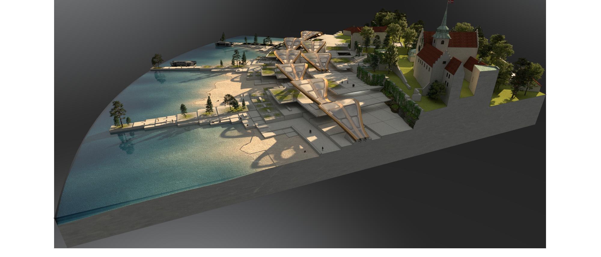
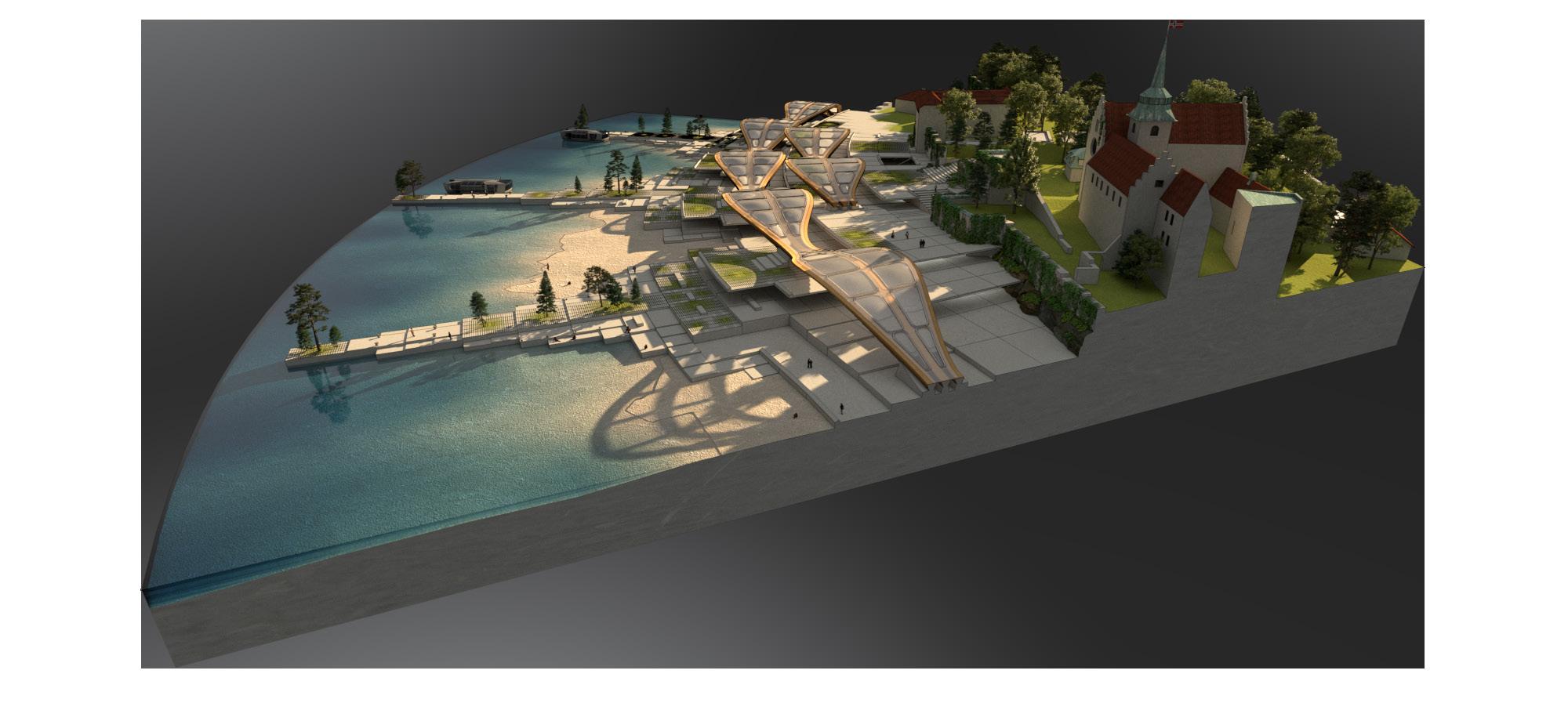
Exploring varied spans for differentiating program under the roof canopy. The fjord with more sand is centered around leisure activities and public use, whilst the adjacent is the transport hub for the water taxis.
69
3 3 4 4 5 5 2 2 1 1 7 6 6 TRANSPORT HUB URBAN FJORD 1 1 7 OFFICE ATRIUM AKVAVIT BAR TRAM CONNECTION 5 5 11 CITY ACCESS OSLO FJORD PARK 3 3 9 WHOLESALE MARKET RECREATIONAL BOAT DOCKING 2 2 8 FORTRESS ACCESS NORTH ENTRANCE LARGE SPAN 6 6 12 AKERSHUS FESTNING RESTURANT MARINA LOUNGE 4 4 10 WHARF 8 12 10 11 9 LEGENDS LEGENDS long span roof short span roof symmetrical unsymmtrical sides

APPENDIX FJORD CITY
lattice lengths
Columns: 9.64 to 11.84m
Diagrid: 7.93 to 12.37m
individual members
Total members: 48
LAP JOINT SUPPORT
LATTICE ROTATED
LATTICE STAGGERED SYSTEM
LATTICE
COLUMN
LATTICE 2B
LATTICE 2A
LATTICE 1B
LATTICE 1A
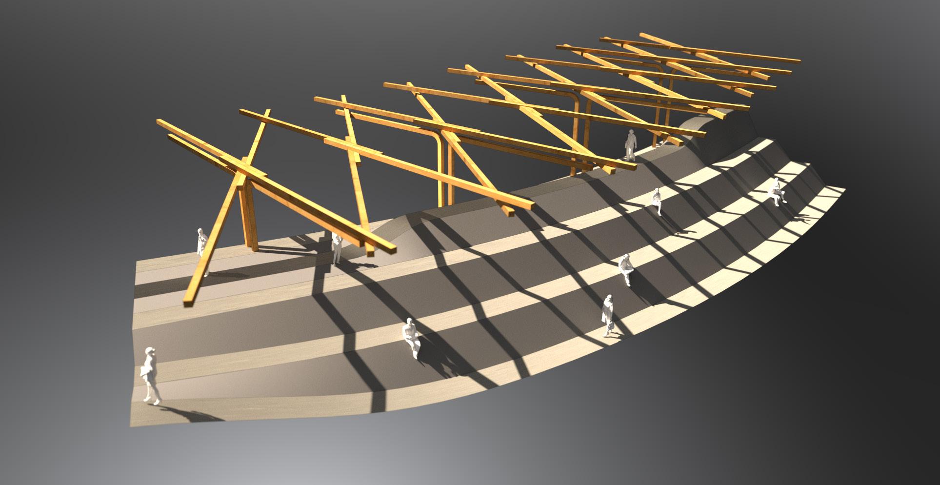
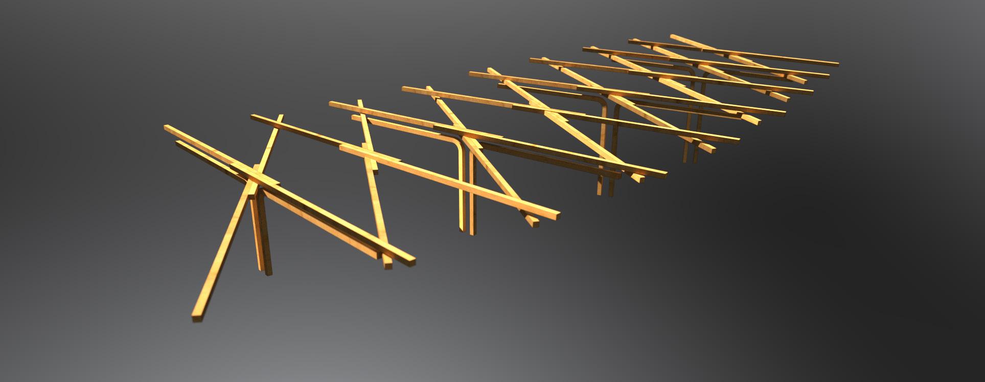
Early stage experiment with a staggered rectilinear lattice canopy that allows for subtle twisting of the roof.

LATTICE LEVEL
CROSS-SECTION EXPLORATIONS
A series of simple cross-sections were developed to investigate a Norwegian cultural re-distribution of scale and program at Akershus Fortress.
PLAN ITERATION 01
Radial configuration of multiple quays centered around one reference point. Wholesale market and ferry terminal are developed with the clash of two languages by which informed the pixelation landscape further on.
All work produced by Unit 14
Unit book design by Charlie Harriswww.bartlett.ucl.ac.uk/architecture
Copyright 2021
The Bartlett School of Architecture, UCL All rights reserved.

No part of this publication may be reproduced or transmited in any form or by any means, electronic or mechanical, including photocopy, recording or any information storage and retreival system without permission in writing from the publisher.

-

@unit14_ucl UNIT


 Cover design by Charlie Harris

