
NIKITA NORRISYEAR 4 @unit14_ucl UNIT Y4 NN
FUTURE OF SIBERIA
All work produced by Unit 14
-
www.bartlett.ucl.ac.uk/architecture
Copyright 2021
The Bartlett School of Architecture, UCL All rights reserved.

No part of this publication may be reproduced or transmitted in any form or by any means, electronic or mechanical, including photocopy, recording or any information storage and retrieval system without permission in writing from the publisher.

@unit14_ucl
 Cover design by Charlie Harris
FUTURE OF SIBERIA
REGIONAL GOVERNMENT CLOISTER
This project focuses on the region of YamaloNenets Okrug within the eastern half of the Russian Federation. For the past few decades, Siberia has faced a decline in investment and economic growth, leading to population decline and derelict infrastructure. This decline is further accelerated by the melting of permafrost, posing a risk to the future of Siberia and its people.

For prosperity to be achieved, this project proposes the region of Yamalo-Nenets to break away from the Russian Federation that has so far hindered its progression. Through architectural intervention, a new administrative building will be conceived as the central body for self-autonomy. This will be based off the historically successful orthodox cloister, a form of religious governance that ruled swathes of Russian land since the thirteenth century. The region of Yamalo Nenets has been chosen for its population of mostly Russian Orthodox believers, a demographic that will have greater potential of success in religious governance.
The new government cloister’s construction will lead through example, using techniques that will allow it to function within a region of permafrost and extremely harsh environment. The building will promote CLT as a new modern method of construction for the region due to the abundance of coniferous trees. A new CLT factory will be constructed for the purpose of the cloister and urban building in the future. It will also pioneer as a self efficient system, harnessing the raw power and resource of the Siberian taiga for its progression as a renewable state approaching the latter half of the 21st Century. Although a harsh landscape in the current milieu, Siberia will become the world’s new economic powerhouse within our lifetime due to global rising temperatures.
The cloister aims to solidify the validity of the new state, with the ambition of creating a new settlement around it. Due to the richness of gas and oil reserves in the region, the potential for state prosperity is achievable. The symbolic nature of the building provides an opportunity for leaving its remains as a monument to the new state, a piece of its history left for future citizens.

NIKITA NORRIS YEAR 4
nikitanorrisarch@gmail.com @niki_arch_work
Y4 NN
YAMALO-NENETS OKRUG, SIBERIA, RUSSIA

TIMBER - SYSTEM EXPLORATION
RESEARCH ARTEFACT - SHIPBUILDING ARCHITECTURE
SHIPBUILDING ARCHITECTURE - DETAIL EXPLORATION
RESEARCH ARTEFACT - GRIDSHELL ARCHITECTURE
GRIDSHELL ARCHITECTURE - FRAGMENT
CHOSEN SYSTEM - SLOTTED PLATE ARCHITECTURE
SYSTEM EXPLORATION - CONCEPT 1
SYSTEM EXPLORATION - CONCEPT 2
ARTEFACT CONCEPT PROPOSAL
BRIEF DEVELOPMENT
GENERAL CONTEXT
ARCTIC CLIMATE
ARCTIC TRADE ROUTES
RUSSIAN FEDERATION - ASSETS
YAMALO NENETS - STATISTICS
INITIAL SITE INFORMATION
RUSSIAN FEDERATION - GOVERNANCE
RUSSIAN ORTHODOX RELIGION
RUSSIAN ORTHODOX CHURCH - STRUCTURE
CLOISTER GOVERNANCE
BRIEF - GOVERNANCE PROPOSAL
SECULARISED GOVERNANCE
UN - MEMBERSHIP
BRIEF - PERMAFROST
SELF RELIANCE
SELF RELIANCE - ENERGY SOURCE
FUTURE EXPANSION PROPOSAL
DESIGN DEVELOPMENT
CONSTRUCTION STRATEGY PROPOSAL
SYSTEM RESEARCH - LOCAL TIMBER
SYSTEM RESEARCH - CLT
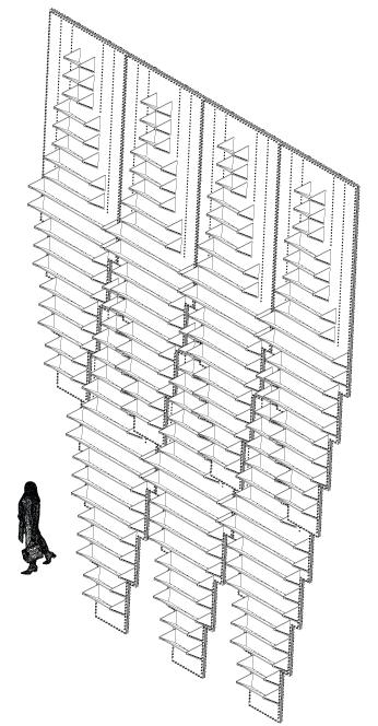
SYSTEM PROPOSAL - SLOTTED CLT
SYSTEM OPPORTUNITY - MEGA SHINGLE
FORM REFERENCE - 1A
FORM REFERENCE - 1B
FORM REFERENCE - 2A
FORM REFERENCE - 2B
FORM INSPIRATION
FORM EXPERIMENTATION - 1
FORM EXPERIMENTATION - 2A
FORM EXPERIMENTATION - 2B
FORM EXPERIMENTATION - 3A
FORM EXPERIMENTATION - 3B
FORM EXPERIMENTATION - 3C
BUILDING GENESIS
SPATIAL ARRANGEMENT - PLAN
SPATIAL ARRANGEMENT - SECTION
MATERIAL PROPOSALS
DETAILED DESIGN
SECTIONAL STUDY
TIMBER FABRICATION A
TIMBER FABRICATION B
PLINTH FABRICATION
CONSTRUCTION SEQUENCE A
CONSTRUCTION SEQUENCE B
PRIMARY STRUCTURE
SECONDARY STRUCTURE
BUILDING LOADS STONE PLINTH LEVEL
ENVIRONMENTAL CONSIDERATIONS
ENVIRONMENT SECTIONAL STUDY
PERMAFROST
PERMAFROST - COOLING STRATEGY
THERMAL PERFORMANCE
THERMAL PERFORMANCE - ENVELOPE
FORM FACTOR
SOLAR STRATEGY
SOLAR PERFORMANCE - GENERAL
SOLAR PERFORMANCE - ATRIUM
INTERNAL VENTILATION
ATRIUM FIRE STRATEGY 05
FINAL DRAWINGS
GROUND FLOOR PLAN
FIRST FLOOR PLAN
FIFTEENTH FLOOR PLAN
ROOF PLAN
SECTION A
SECTION B
ISOMETRIC
FRONT ELEVATION
EXTERNAL NIGHT SCENE - ARRIVAL
EXTERNAL DAY SCENE
INTERNAL SCENE - CHURCH
INTERNAL SCENE - PUBLIC PLAZA
INTERNAL SCENE - ASSEMBLY HALL
INTERNAL SCENE - ATRIUM
01
02
03
04
CONTENTS 4 53 14 76 32

01 TIMBER - SYSTEM EXPLORATION
No.3 Covered Slip - Chatham Royal Dockyard
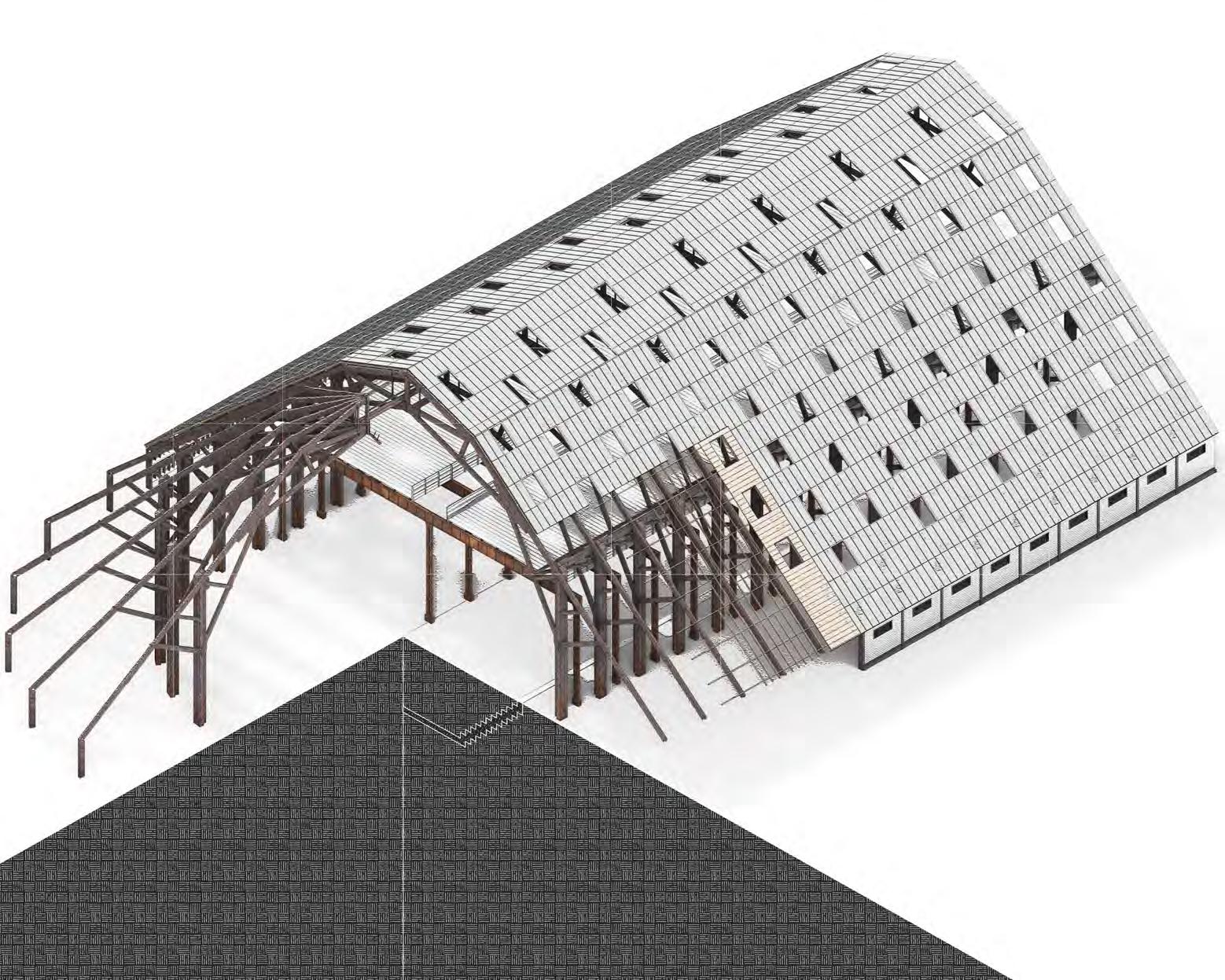
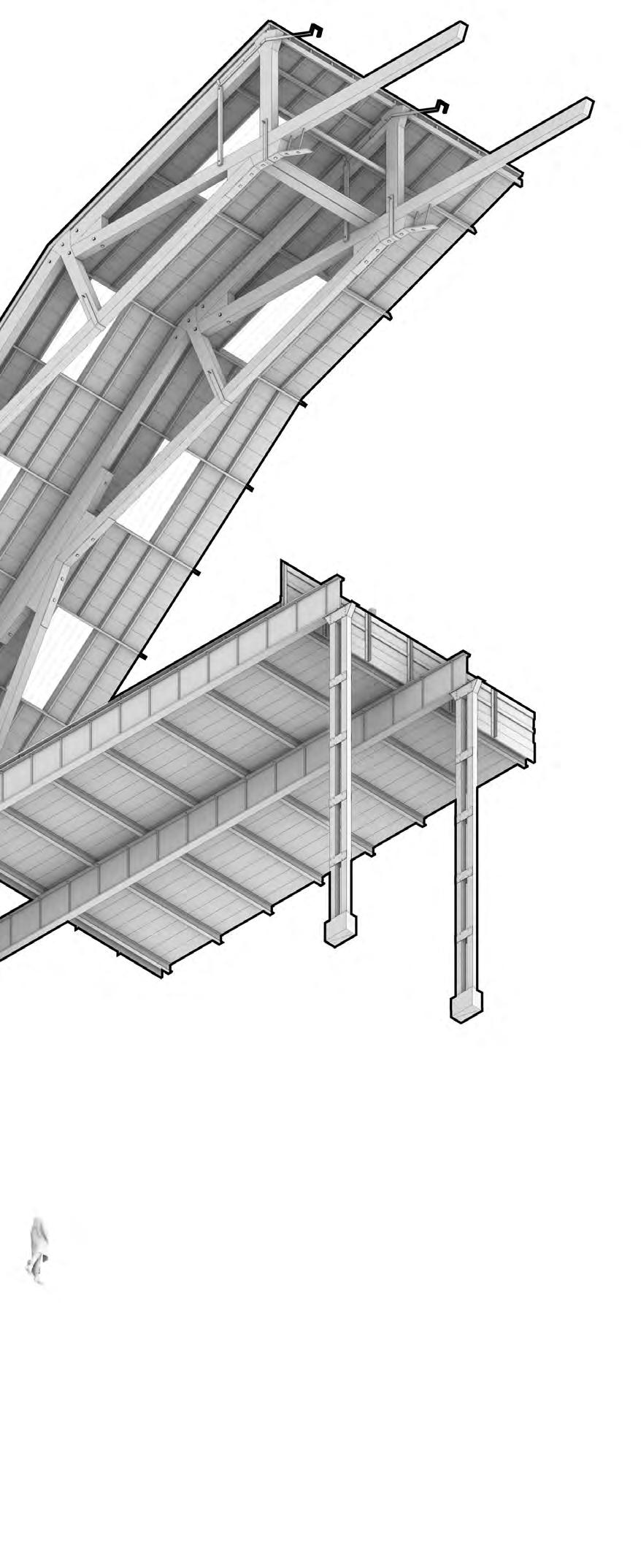
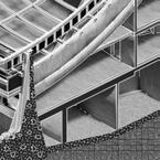
Built in 1838, the No. 3 Covered Slip at The Historic Dockyard Chatham was the largest wide span timber structure in Europe at the time. Today it serves as a museum which houses an array of objects / vehicles.
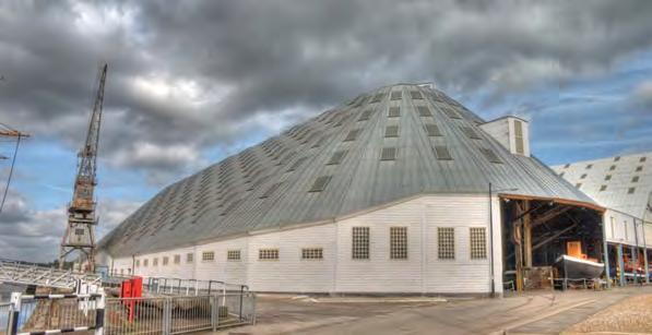

The need to cover slips and docks was born out of necessity due to the impact that dry rot had on ships during construction. Designed by Sir Robert Seppings, the No.3 Slip stood at the cusp of technological change with its wide span timber cantilever roof.
Over the course of over a century the slip underwent major renovations, including the addition of a 1st floor deck for storage, the filling of the ground and re-cladding of the external treatment. As things were added over time, an irregularity in construction was born, giving a make-shift aesthetic to the structure that stands today.
5
TIMBER - SYSTEM EXPLORATION RESEARCH ARTEFACT - SHIPBUILDING ARCHITECTURE
NIKITA NORRIS2022-2024 SECTION 01 BARC0174ADVANCED ARCHITECTURAL DESIGN PORTFOLIO
The covered slip has undergone many renovations since it was built, allowing it to remain functional for 200 years.
TIMBER - SYSTEM EXPLORATION
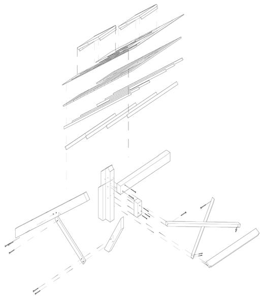
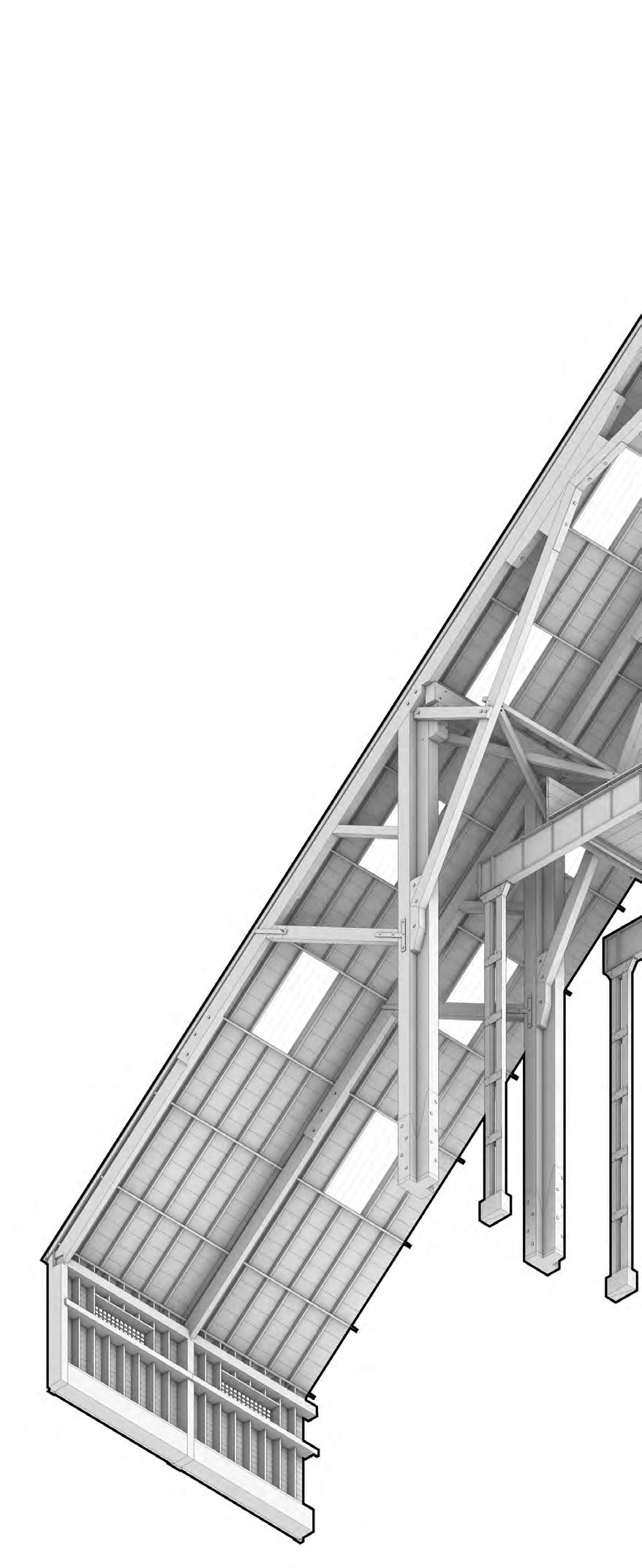
SHIPBUILDING ARCHITECTURE - DETAIL EXPLORATION
Arrangement in Cross-Section
The slip was built in 1836 and the cover for it followed in 1838 with a roof 91 metres long and 44.5 metres wide.
By the 1850’s the slipway was no longer adequate for ships that were being constructed at the time and in 1904 a mezzanine floor was built to create a store for ships’ boats.
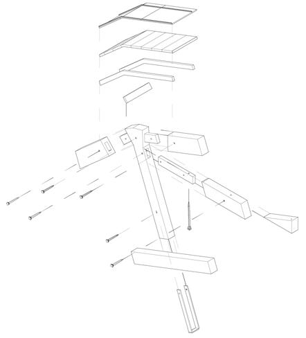
External Envelope Build Up
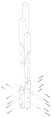
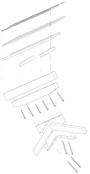
Column-Beam Connection

Column-Base Connection
6
NIKITA NORRIS2022-2024
Column-Beam Connection

Column-Base Connection
7 External Envelope Build Up
SECTION 01 BARC0174ADVANCED ARCHITECTURAL DESIGN
PORTFOLIO
SYSTEM EXPLORATION
RESEARCH ARTEFACT - GRIDSHELL ARCHITECTURE

Precedent - Mannheim Mulltihalle
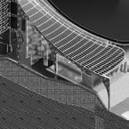
This page delves into the structure of the timber gridshell. The use of timber within this construction method was pioneered by the German architect Frei Otto. Using the Mannheim Multihalle as my precedent, I have developed several tests into form finding.
The Mannheim Multihalle offers wide span spaces devoid of columns for structural integrity. A multi layered hemlock lath system is implemented to achieve this.
No Bending - Square Before Compression
Bending - Rhombus After Compression


The ability to bend a gridshell structure is made possible through the change of form from a square to a rhombus.
Mannheim Multihalle - Gridshell Components
The primary structure of the gridshell is composed of two layers of hemlock laths set perpendicular to each other and stacked upon one another. Cables are placed through every sixth node for additional stiffness.
Compression Forces
For the structure to stand up the build-up is reliant on compression forces. Through this force the laths bend into a rhombus shape and slide over each other, made possible by slotted holes in the node joints.
Net Test
These tests use primary shapes to develop an understanding of the forms that are created as a result of its “net”.
Net Test
The next test uses a more complex net to create a more intriguing form. As it is not a continuous form and has points of structural weakness, timber and concrete have been used to maintain compression.
Base Detail
Concrete and steel are implemented to maintain the high compressive forces created by the lath gridshell. Connections between the lath and steel are bolted through intermediary 2 x 25mm plywood boards.
8
TIMBER -
NIKITA NORRIS2022-2024 SECTION 01 BARC0174ADVANCED ARCHITECTURAL DESIGN PORTFOLIO
Using the idea of a roof being the primary definition of a building, there is a blurring of what is wall and roof, acting predominantly as an enclosure. This fragment takes a linear approach to form finding, using two different scales to divide space.

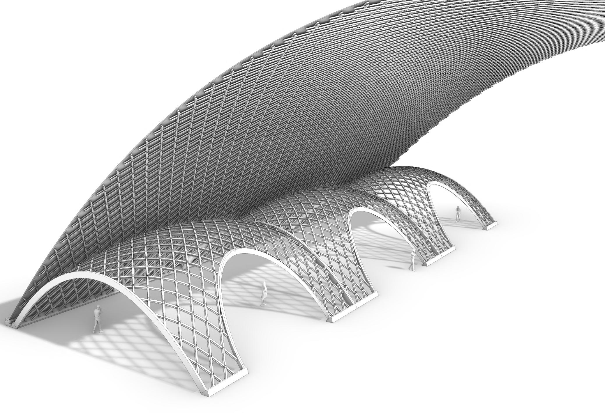
9
TIMBER - SYSTEM EXPLORATION GRIDSHELL ARCHITECTURE - FRAGMENT
Fragment One
NIKITA NORRIS2022-2024 SECTION 01 BARC0174ADVANCED ARCHITECTURAL DESIGN PORTFOLIO
TIMBER - SYSTEM EXPLORATION

CHOSEN SYSTEM - SLOTTED PLATE ARCHITECTURE

Precedent - Theatre Vidy
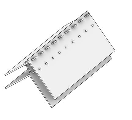
Designed by Yves Weinand, this timber pavilion is constructed from CLT panels that interlock with each other, negating the need for additional materials. The complex geometrical forms that are created from it provide additional structural integrity.
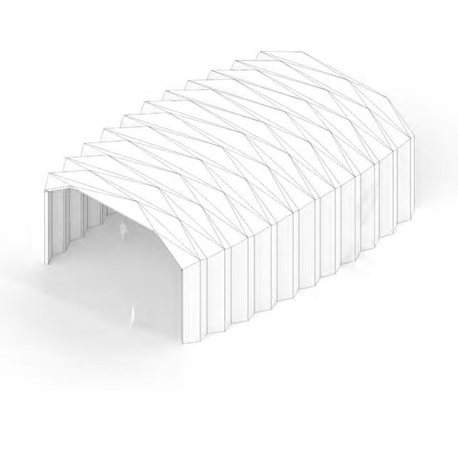
Wood-Wood Interlocking System

10
Looking at the detailing for the theatre pavilion, the build-up incorporates a doubling of panels that interlock together with dovetail wood-wood joints. The result is unique as it acts as both a load-bearing structure and a cladding (which decreases building cost).
NIKITA NORRIS2022-2024 SECTION 01 BARC0174ADVANCED ARCHITECTURAL DESIGN PORTFOLIO
TIMBER - SYSTEM EXPLORATION SYSTEM EXPLORATION - CONCEPT 1
Idea 1 - Experimentation
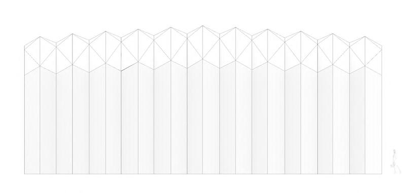
Using the origami layout shown on the right as a starting point, the form is experimented with by use of mirroring, scale manipulation, and arrangement. The intent of this investigation is to create a continuous architecture through means of addition.
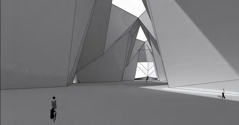

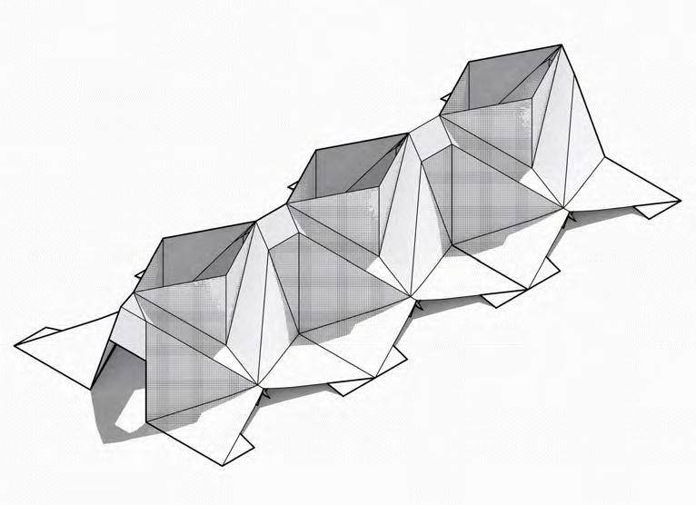
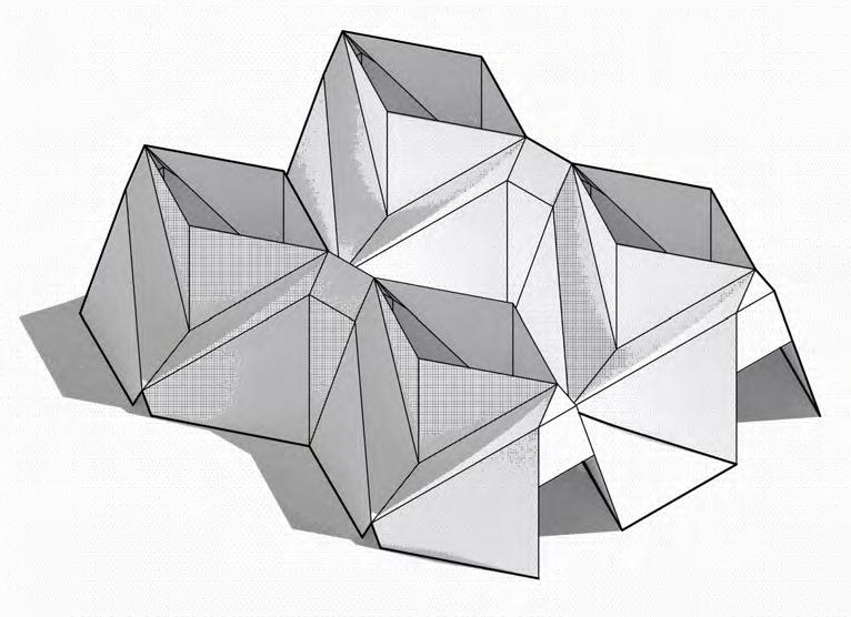
Central Test


By arranging forms around a centre point, interventions can be found when these forms clash and intervene. By merging them in this example, a walkway is created between the voids formed.
Linear Test
Taking a linear approach, the overall interior space is viewed as a whole despite their distinct repetition. Continuity is explored here as a relationship with the environment, making it seem the building folds out of the ground.
11
NIKITA NORRIS2022-2024 SECTION 01 BARC0174ADVANCED ARCHITECTURAL DESIGN PORTFOLIO
TIMBER - SYSTEM EXPLORATION

SYSTEM EXPLORATION - CONCEPT 2
Idea 2 - Experimentation
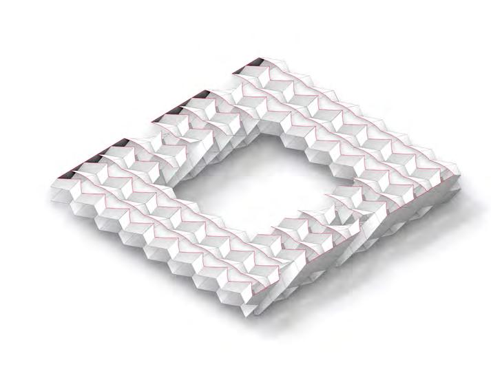
The origami pattern shown here was chosen due its repeatability along the horizontal and vertical axis., Allowing for an architectural continuity. This page proposes an all-en-composing environment similar to the works of Super Studio and Archigram.


Form Finding
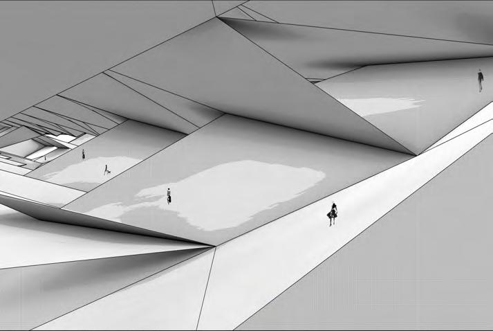
Space is activated through movement and circulation.
The aim of this investigation was to explore how people could move in this environment, whether side to side or up and down.
12
NIKITA NORRIS2022-2024 SECTION 01 BARC0174ADVANCED ARCHITECTURAL DESIGN PORTFOLIO
TIMBER - SYSTEM EXPLORATION ARTEFACT CONCEPT PROPOSAL
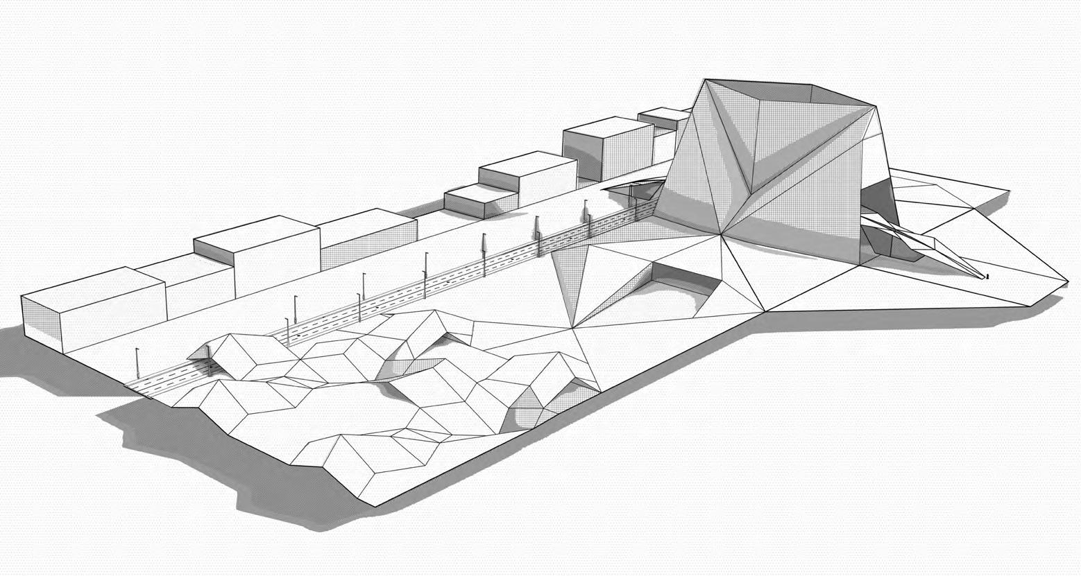
Scale Study - Public Space
Combining the two ideas of form finding, this fragment proposes a public space along a linear axis that acts in addition to the urban space. Following a logic of folding to generate space, a multiplicity of different folding forms can be used to suit different areas of function ( but can still be read as a whole ).

Connection
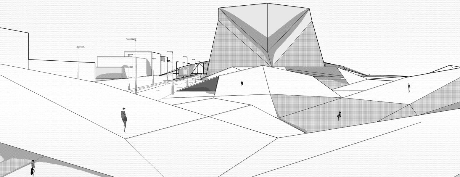
The intent of this fragment was to explore the hierarchy of space / form and whether architectural landmarks / environment can be used to direct flow. An example could be to use larger forms to imply something of greater importance.
Seamless connections between spaces were used to imply a sense of continuity.
13
NIKITA NORRIS2022-2024 SECTION 01 BARC0174ADVANCED ARCHITECTURAL DESIGN PORTFOLIO

Arctic Circle
One of the harshest climates in the world, the Arctic circle and countries that neighbour it experience extremely cold temperature annually. However, with rising global temperatures, this vast region may undergo changes in population and economic potential throughout the 21st Century.


NIKITA NORRIS2022-2024 SECTION 02 BARC0174ADVANCED ARCHITECTURAL DESIGN PORTFOLIO
BRIEF DEVELOPMENT GENERAL CONTEXT
BRIEF DEVELOPMENT
Global Warming
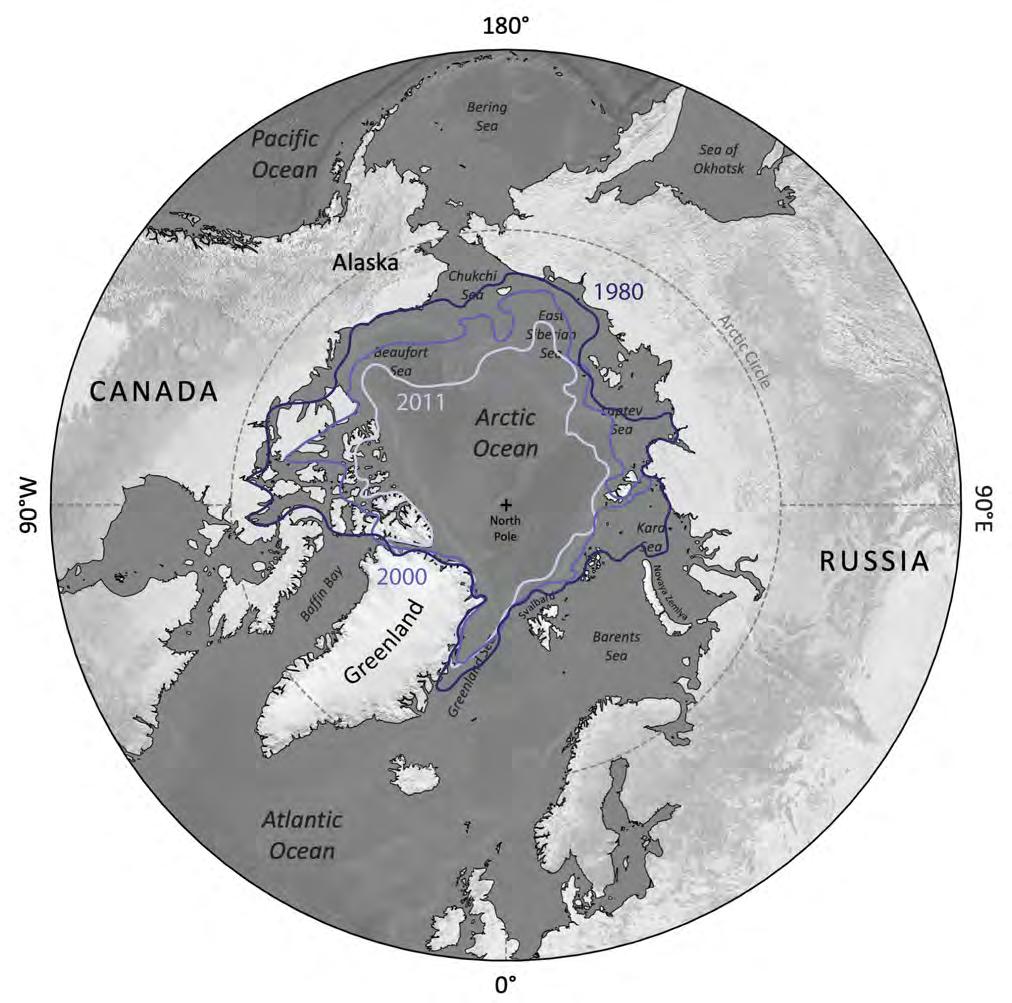
Data from the last 40 years has seen a rapid increase of melting ice in the Arctic circle due to rising temperatures. Where global warming may pose a threat to some nations, it may bring great prosperity to others.
Sea Ice Concentration (Fraction)
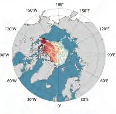
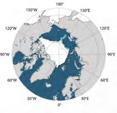
Sea Ice Thickness (m)
Future of the Arctic Region - Climate
Due to global rising temperatures, the northern hemisphere will begin to warm. With the melting of ice and areas of land becoming more hospitable for people, we may see new trade routes open up and a mass migration of people escaping the much warmer south.
Permafrost Temperature


Average Arctic Sea Ice Extent
Arctic Methane Emissions


Age of Arctic Sea Ice

16
NIKITA NORRIS2022-2024 SECTION 02 BARC0174ADVANCED ARCHITECTURAL DESIGN PORTFOLIO
ARCTIC CLIMATE
2018 Data
BRIEF DEVELOPMENT
The Northern Sea Route
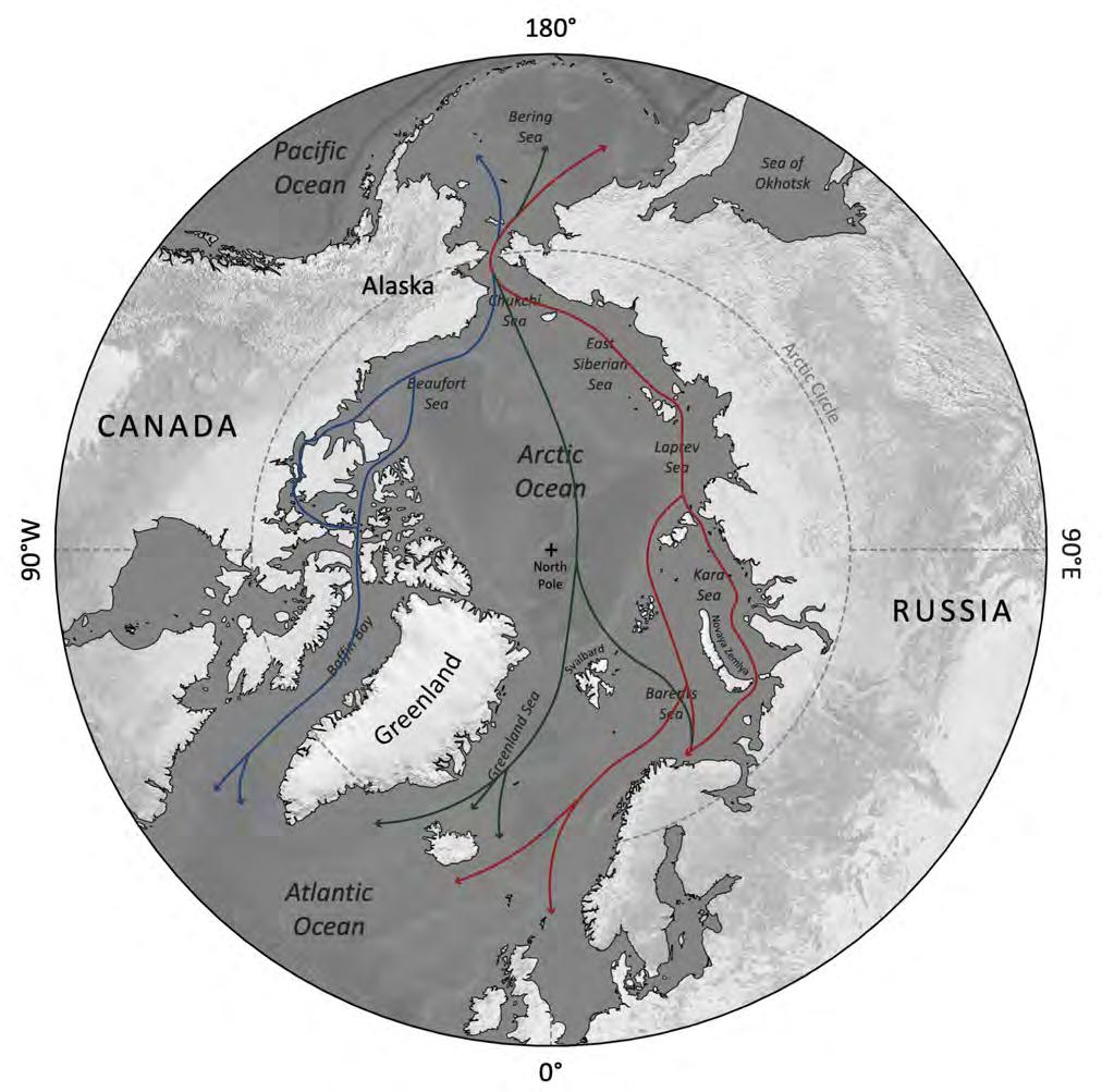
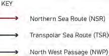
With the melting of Arctic ice, new routes will open up for global trade, most notably the Northern Sea Route (bordering the Russian Federation). This will divert the currently volatile state of existing shipping routes through the horn of Africa, and will open up new areas of investment in other areas of the globe.
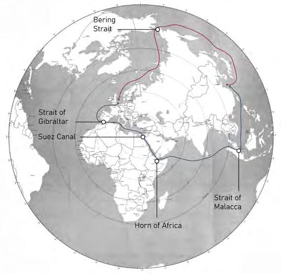
Future of the Arctic Region - Trade
Prosperity may be brought to the northern hemisphere due to the many benefits new Arctic trade routes would bring. Taking up most of the neighbouring land mass around the Arctic circle, regions in Russia will benefit most. This may include the construction of ports that may become the new cities of the future.
NEW
TRADE ROUTE OPPORTUNITY - NSR
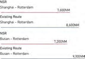

Trade through the Northern Sea route will increase due to the many benefits it brings, most notably the decrease in distance travelled by boats (right).
17
ARCTIC TRADE
NIKITA NORRIS2022-2024 SECTION 02 BARC0174ADVANCED ARCHITECTURAL DESIGN PORTFOLIO
ROUTES
Fuel Consumption NSR Trade Route Benefits Taxes Economic Opportunities Time Piracy Emissions
BRIEF DEVELOPMENT
RUSSIAN FEDERATION - ASSETS
Resources
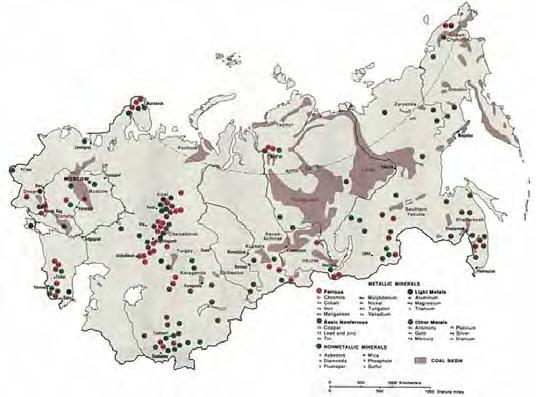
The Russian Federation is rich in resources, may it be in mineral deposits or agricultural land. This however coincides with the lack of sufficient infrastructure to realise its full potential, most notably in Siberia where most resources are found.
FOSSIL FUEL DEPOSITS
GDP
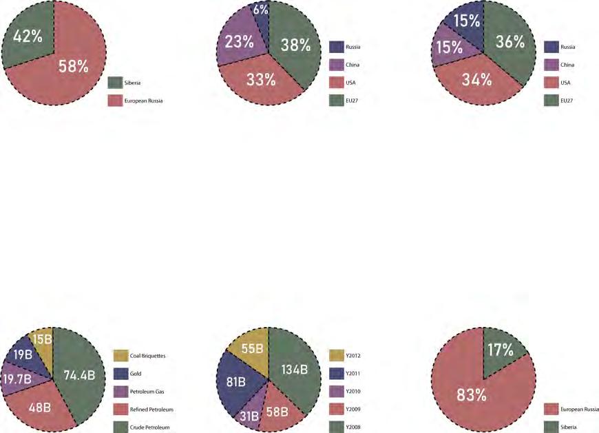
Although larger in area and resources, Siberia makes up less than half of the country’s GDP.
STATISTICS - LACK OF PROSPERITY
Global Comparison - Road Infrastructure
Global Comparison - Railway Infrastructure
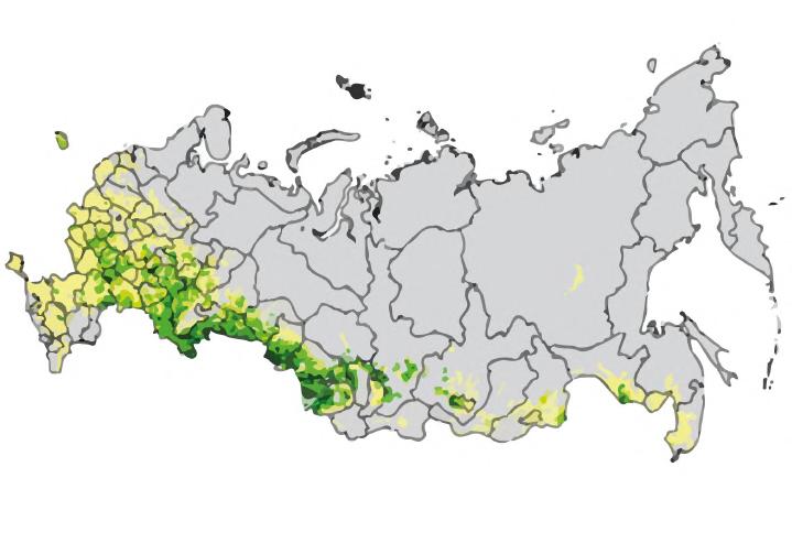
AGRICULTURAL REGIONS
Russia Exports
Russia’s main exports of gas and oil are located within Siberia, most notably the region of YamaloNenets (90%).
Relative to other global powers, Russia has incredibly poor road infrastructure. This may affect the potential ability for commerce in Siberia .
Investment (Siberia)
Investment in Siberia has declined in the 21st century, at a time where derelict soviet infrastructure needs replacing.
Similar to roads, Russia performs poorly. Majority of rail transport in Siberia is allocated to gas/oil exports.
MINERAL DEPOSITS (SOVIET DATA)

Russia - Food Production

Due to a lack of arable soil, Siberia relies heavily on food imports.
18
NIKITA NORRIS2022-2024 SECTION 02 BARC0174ADVANCED ARCHITECTURAL DESIGN PORTFOLIO
SIBERIA WEST EUROPEAN RUSSIA
EAST
BRIEF DEVELOPMENT
Regional Potential
Although situated in Siberia (less economic investment in relation to European Russia), Yamalo Nenets is rich in economic potential due to its vast resources of oil and gas. This is currently extracted by the Russian Federation but most of the money made is not reinvested back into the area, causing regional decline.
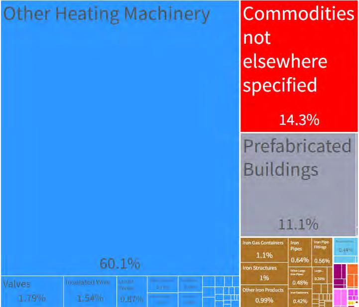


State Economy
As a region that has an excess profit of 3.74 billion US dollars annually (taking into account imports), there is great opportunity for economic prosperity in the region.
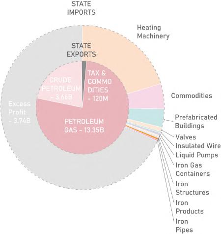
19
NENETS - STATISTICS NIKITA NORRIS2022-2024 SECTION 02 BARC0174ADVANCED ARCHITECTURAL DESIGN PORTFOLIO YAMALO-NENETS OKRUG ANALYSIS REGION EXPORTS / IMPORTS Export - Gas / Oil Economy Imports - Gas / Oil Economy Mineral Products Mineral Products Plastics & Rubbers Machines Machines Miscellaneous Animal Products Stone & Glass Transportation Chemical Products Instruments Instruments Metals Metals Unspecified Unspecified Paper Goods
YAMALO
BRIEF DEVELOPMENT INITIAL SITE INFORMATION
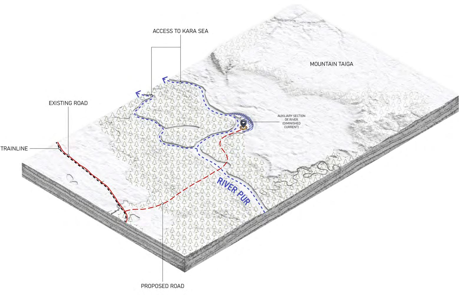
Context
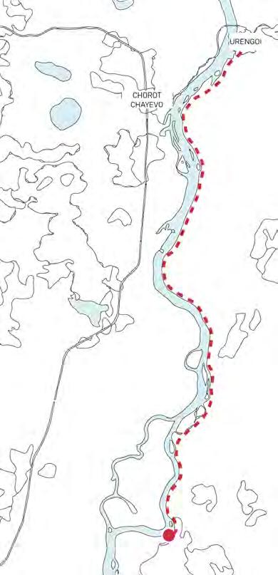
Situated next to the River Pur and one of the few road and railway connections in Yamalo-Nenets, the river peninsula is an ideal location for site access. An abundance of trees within the area provides a sustainable building material for construction.
The site is surrounded by the Siberian mountain taiga, dotted with marshes, lakes and rivers. This makes the access to site difficult and will require a strategy of self reliance.

General Context Analysis
The brief will propose a building that is fully independent in a region that is isolated and harsh. This will include access to fresh water, vegetation and other towns. A peninsula (shown above) along the River Pur fits the requirements of the brief. Due to its location, access can be gained into the Kara Sea, an aspect that is vital for global trade.

Peninsula Adjacencies
Due to strong river currents, a bay within the peninsula provides an optimum port for safe operation. The peninsula also creates natural defence against dangerous wildlife, with minor access through a choke point in the west. Although locally isolated, the nearest city Urengoi is located 25 miles away and is accessible by river.
20
Site River Pur Road/Railway NIKITA NORRIS2022-2024 SECTION 02 BARC0174ADVANCED ARCHITECTURAL DESIGN PORTFOLIO
BRIEF DEVELOPMENT
RUSSIAN FEDERATION - GOVERNANCE


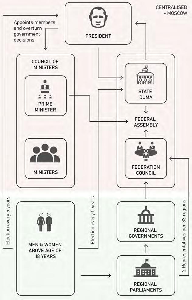
Centralised Governance
Currently, the Russian Federation operates as a single entity (Kremlin) that governs 17.2 millions square kilometres of Russia. Although providing many benefits, the lack of autonomous local governance creates a decline in economic prosperity (most notably Siberia).

CENTRALISED GOVERNANCE
Russian Federation
Centralised Government Administration Centre - Moscow

Governed Regions - 83
Land Area - 17.2 million km2
GOVERNMENT STRUCTURE
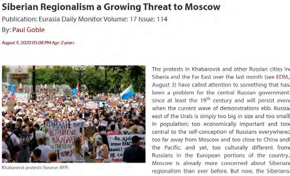
SIBERIA - DEMAND FOR REGIONALISM
C
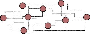
P roposal - De-Centralised Government
Although there is presence of regional governments within the Russian government, they hold no true power and act in proxy to the Kremlin. This has led to decline in Siberia, leading to a growing desire for regionalism.
21
NIKITA NORRIS2022-2024 SECTION 02 BARC0174ADVANCED ARCHITECTURAL DESIGN PORTFOLIO
urrent - Centralised Government
BRIEF DEVELOPMENT
RUSSIAN ORTHODOX RELIGION
Dominant Religious Body - ROC
As the dominant religion of Russia, Russian Orthodoxy plays a pivotal role in the daily lives of citizens. With a strong historical legacy of governing people, faith may provide an alternative method of governance.
RUSSIAN FEDERATION - FAITH
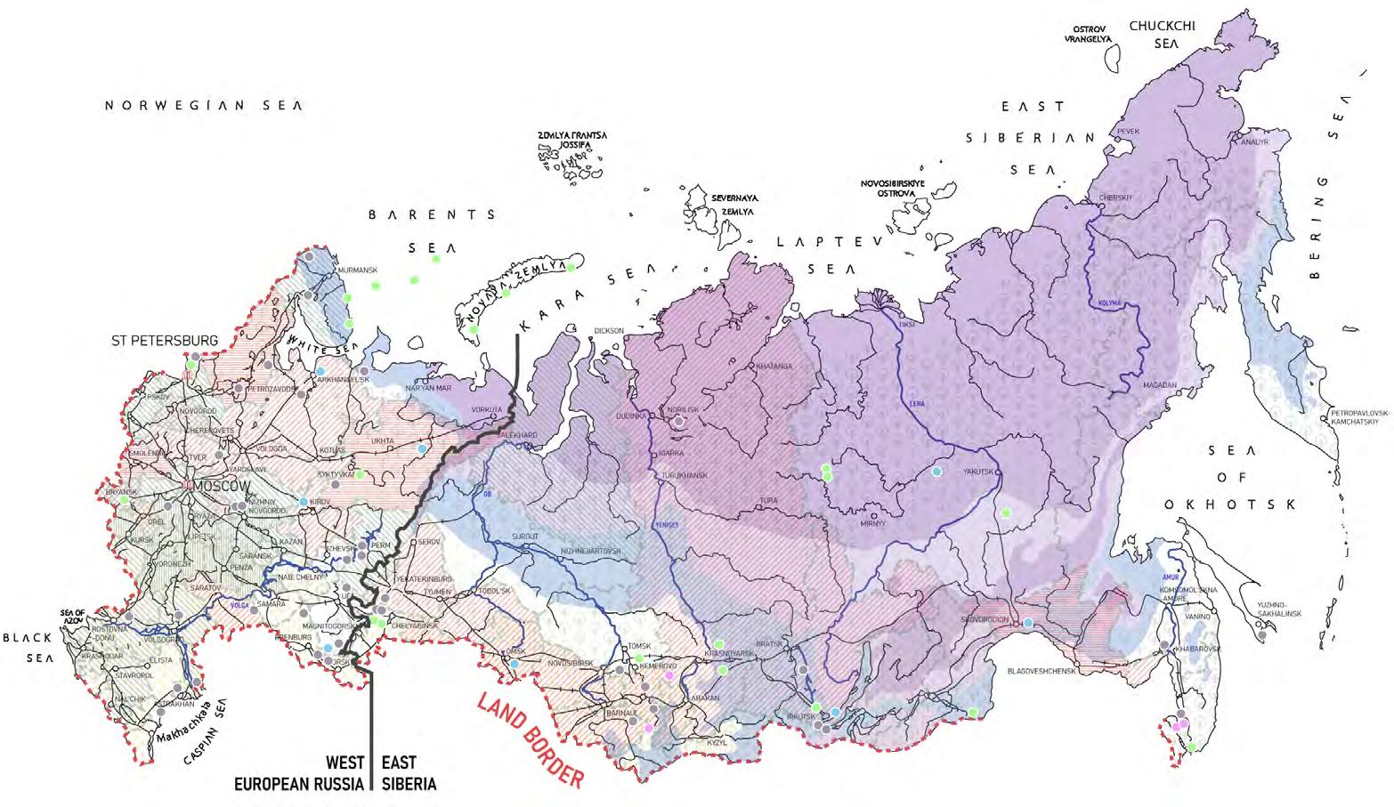
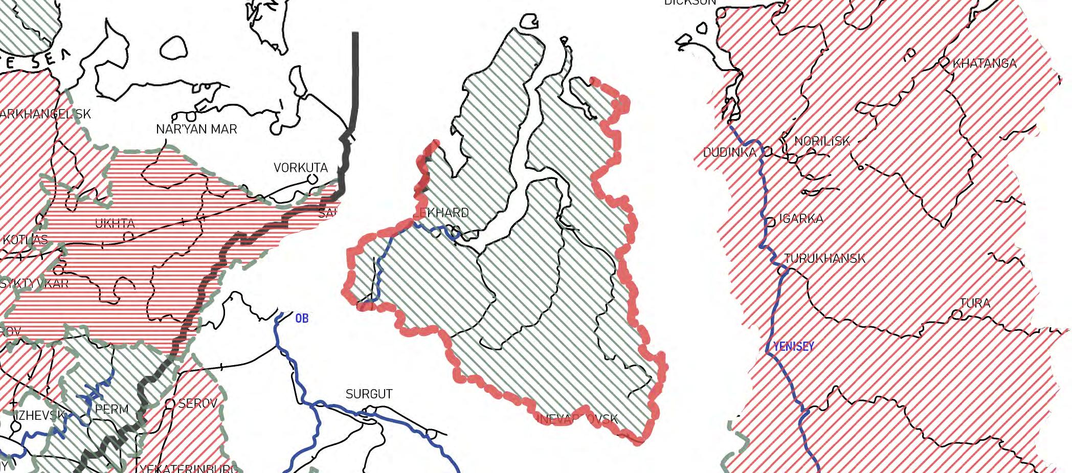
Russian Orthodoxy - East / West Divide

Map of Russia denoting region percentages of Orthodox (Green) and Spiritual (Red) believers. An opportunity is found in the only high percentage of orthodox believers in Siberia, The Yamalo Nenets Okrug (outlined in red).

EXTERNAL INFLUENCES
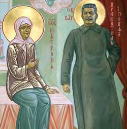
Throughout Russia’s history, the Russian Orthodox Church (ROC) politically aligned to the most dominant power structure, such as the Soviet Union and the Mongol Empire.
The Russian Federation, currently led by an authoritarian party (Edinaya Rossia) holds close ties with (ROC). If a region in Russia were to be given greater autonomy, it would suggest that ties to both of these bodies would need to breakaway.

Mongolian EmpireROC (1250’s) benefits greatly from exemptions. Soviet UnionROC (1930’s) embraces Joseph Stalin and Communist Party.

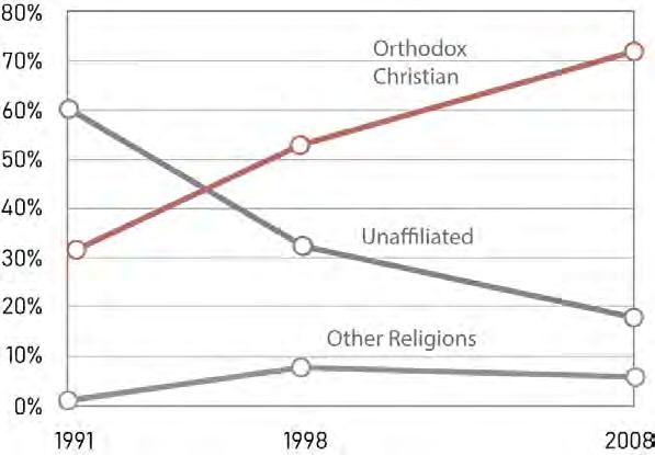
ORTHODOX FAITH - POPULATION BREAKDOWN

Major Religious Groups (1991-2008)
With a population of 143 million people, Russian orthodoxy holds the majority in religious belief (72%). This has rapidly grown from 31% back in 1991. This allows for greater influence and power for the ROC within the Russian Federation.
22
NIKITA NORRIS2022-2024 SECTION 02 BARC0174ADVANCED ARCHITECTURAL DESIGN PORTFOLIO
BRIEF DEVELOPMENT
RUSSIAN ORTHODOX CHURCH - STRUCTURE
Leadership Organisation
Much like the government of the Russian Federation, the Russian Orthodox Church (ROC) is heavily centralised (Eparchy of Moscow). This may lead to an imbalance of decision making, in regards to the interests of other eparchies.
PATRIARCH
- Extensive administrative powers
- No canonical jurisdiction outside diocese of Moscow
SYNOD
7 permanent members
EPARCHY (EQUIVALENT TO DIOCESE)
(261)
SELF-GOVERNING EPARCHY
Estonian Orthodox Church of Moscow Patriarchate
Latvian Orthodox Church
Moldovan Orthodox Church
Ukrainian Orthodox Church
SMALL EPARCHY
LARGE EPARCHY EXARCHATE
BISHOP METROPOLITAN ARCHBISHOP (& BISHOPS)
METROPOLITAN ARCHBISHOP (& BISHOPS)
METROPOLITAN ARCHBISHOP (& BISHOPS)
TOTAL PARISHES (34,764)
23
NIKITA NORRIS2022-2024 SECTION 02 BARC0174ADVANCED ARCHITECTURAL DESIGN PORTFOLIO
BISHOP’S COUNCIL Only Bishops
LOCAL COUNCIL Assembly of Bishops, Clergy & Laity
PARISH PARISH PARISH
FATHER SUPERIOR PRIEST FATHER SUPERIOR PRIEST FATHER SUPERIOR PRIEST PRIESTS PRIESTS PRIESTS
BRIEF DEVELOPMENT
Brief Proposal - Religious Governance
Historically, the Russian Orthodox Cloister had proved successful in governing localised regions of Russia. Cloister’s acted as miniaturised cities around the land it governed. This typology provides an opportunity of governance for the region of Yamalo Nenets.

4
Russian Orthodoxy - East / West Divide
Map of Russia denoting region percentages of Orthodox (Green) and Spiritual (Red) believers. An opportunity is found in the only high percentage of orthodox believers in Siberia, The Yamalo Nenets Okrug (outlined in red).
Following similar conventions of Russian Orthodoxy Leadership, Yamalo Nenets will be considered as an eparchy, led by a council of bishops with the archbishop as the head (each bishop acts as a constituent of a region within Yamalo Nenets). Sections of yamalo Nenets will be divided into parishes (either a town or city). Each Parish is led by a Father Superior Priest. Every person within this structure is re-elected every 4 years to ensure regional prosperity.
SELF-GOVERNING EPARCHY
ARCHBISHOP (& BISHOPS)
PARISH (126)
FATHER SUPERIOR PRIEST
24
CLOISTER GOVERNANCE NIKITA NORRIS2022-2024 SECTION 02 BARC0174ADVANCED ARCHITECTURAL DESIGN PORTFOLIO 988AD Kiev Rus accepts Christianity as state religion. 1200’s ROC’s governing activities begin. 1943 ROC embraces Joseph Stalin and Communist Party. 1480 Muscovy ends Mongol Yoke. ROC switches alliance to victor. 1800’s State begins return of economic power to ROC. 1564 ROC privileges stripped by Ivan the Terrible after coup. 1400’s-1500’s Josephite movement begins within ROC. ROC gains greater influence after defeat of Landowning Boyars. 1250’s Rus conquered by Mongol horde. ROC benefits from exemptions and privileges. 1861 End to Serfdom in Russia. 2023AD Russian Orthodox Church Monasteries - 474 Convents - 498 Dioceses - 314 Parishes - 38,649 Functions of Cloister Monasteries - 550 Convents - 475 ROC cloisters land ownership1800’s 34 Monasteries - 243 acres p M 14 Monasteries - 108 acres p
Monasteries
M 45
- 567 acres p M 87 Churches - 2,700 acres p C
11 Churches - 6,750 acres p C
Monasteries
approx land
2,700,000
Religious Social Culture Security Power Economic
ORTHODOX LEADERSHIP STRUCTURE YAMALO-NENETS BRANCH HISTORIC TYPOLOGY - RUSSIAN CLOISTER HOUSEHOLD YARD 9. 9. 10. 10. 11. 11. 12. 12. 13. 13. 14. 14. 15. 15. 16. 16. 1. 1. 2. 2. 3. 3. 4. 4. 5. 5. 6. 6. 7. 7. 8. 8. TOWER KVAS FACTORY FRATERNAL CORPS TREASURY ICON SHOP ABBOT’S CORP CHURCH / BELL TOWER CANDLE WORKSHOP CHURCH CHAPEL CATHEDRAL CHURCH OF THE ICON FRATERNAL CORPS CHAPEL CLOISTER
- 40,494 acres p M Total
owned by ROC -
acres
SUCCESSFUL GOVERNANCE OF CLOISTERS NEW
DEFENSIVE WALLS
PRIEST
BRIEF DEVELOPMENT
Proposal for Prosperity
This brief proposes constitutional autonomy for the region of Yamalo Nenets. This will include breaking away from both the Russian Federation and the Russian Orthodox Church. This separation is proposed as a means to bring prosperity to the region.
BREAKAWAY REGION PROPOSAL
NEW LEGISLATION BENEFITS TO EXISTING CONCERNS
Permafrost - Infrastructure Strategy

Due to the lack of investment and deteriorating infrastructure under the current government, autonomy would allow for reinvestment.
As Yamalo-Nenets spans a large area and has poor connections, local governance will be exercised by parishes already situated in towns.

Population Increase - Migration

With a declining population, migration may be a useful short term strategy for faster prosperity in the region.

NEW
SELF-GOVERNING RUSSIAN ORTHODOX CHURCH BRANCH

List of self-governing branches of the ROC.

Ukrainian Orthodox Church

Belarusian Orthodox Church
Yamalo Nenets Orthodox Branch

Due to concerns regarding the influence that the Russian Federation has over the ROC, the brief proposes a self-governing branch to maintain state autonomy. This option has proved successful for existing branches.
Pakistan Orthodox Church
Japanese Orthodox Church


Estonian Apostolic Orthodox Church
Latvian Orthodox Church
OIL / GAS STATE PRECEDENT - QATAR
State Prosperity
Income - Regional Investment

Most money made from exports is kept by the Russian Federation and is not invested back into the region. As an autonomous state, all money will be kept locally. Looking to global markets, foreign investment can benefit Yamalo-Nenets
Both Yamalo Nenets and Qatar share an equally harsh climate. However, gas and oil fields have ensured economic prosperity for Qatar, giving proof that Yamalo Nenets may prosper as well.

25
- GOVERNANCE
NIKITA NORRIS2022-2024 SECTION 02 BARC0174ADVANCED ARCHITECTURAL DESIGN PORTFOLIO
BRIEF
PROPOSAL
Local Parish Governance
BRIEF DEVELOPMENT SECULARISED GOVERNANCE
Leadership Organisation
The structure of the new branch of Russian Orthodoxy will take the form of current Eparchy structures. However, governance will be split between clergy and new government bodies, creating a bipartisanal relationship. All bodies of the new state will convene at the state assembly.
YAMALO NENETS EPARCHY (CLOISTER)
SECRETARY COUNCIL
- Protects interests of state
- Key decision making
- Power to veto decisions made by Bishop’s council and Archbishop (2/3 majority)
- Each Secretary is in charge of a department
DEPARTMENT FOR BUSINESS & TRADE
DEPARTMENT FOR CULTURE, MEDIA & SPORT
DEPARTMENT FOR EDUCATION
DEPARTMENT FOR ENERGY SECURITY
DEPARTMENT FOR FOOD & RURAL AFFAIRS
DEPARTMENT FOR HOUSING
DEPARTMENT FOR SCIENCE, INNOVATION & TECHNOLOGY
DEPARTMENT OF HEALTH
DEPARTMENT OF FOREIGN POLICY
YAMALO NENETS
TREASURY
MINISTRY OF DEFENCE
MINISTRY OF JUSTICE
DEPARTMENT FOR WORK & PENSIONS
DEPARTMENT FOR TRANSPORT
PRESIDENTIAL ARCHBISHOP
- Partial administrative powers
- No canonical jurisdiction outside eparchy of Yamalo Nenets
BISHOP COUNCIL
- Administration of religious doctrine
- Decision making over regional interests
STATE ASSEMBLY
- Body made up of Archbishop, Bishops, Secretaries, Parishes, representatives and general public
PARISH (126)
FATHER SUPERIOR PRIEST
PRIEST
26
NIKITA NORRIS2022-2024 SECTION 02 BARC0174ADVANCED ARCHITECTURAL DESIGN PORTFOLIO
State Validation
To validate the new state of Yamalo Nenets, membership to the United Nations will be proposed. Validation by other nations will ensure the success of the new state.
MEMBERSHIP CONTENTION
As a breakaway region, there are a few countries that would not recognise YamaloNenets as a self governing state (notably Russia and China). However, many states in the past have gained membership despite this. (highlighted in red).
UN MEMBERSHIP APPLICATION PROCESS
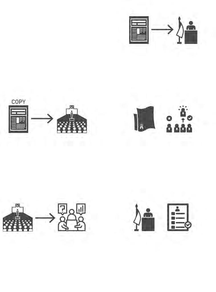
Applicant State - Yamalo-Nenets
Autonomous State
As a breakaway region of the Russian Federation, YamaloNenets will need to apply for UN membership as a means to validate its independence. Global recognition would be the first step to prosperity in the region.
1. Application (Rule 134) Yamalo-Nenets submits application to UN Secretary General. Applicant must state declaration in accordance to UN Charter.
2. Notification of Application (Rule 135)
Secretary General sends copy (information only) of application to General Assembly.
3. Consideration and Decision Thereon (Rule 136)
If Security Council recommends applicant for membership, General Assembly will consider applicant’s willing to meet charter obligations. A two-thirds vote majority is needed for a successful application.

4. Non-Recommendation (Rule 137)
If not recommended by General Assembly, application is sent back to Security Council for further consideration.
5. Notification of Decision and Date of Membership (Rule 138)
Secretary General will inform applicant of General Assembly vote. If approved, membership is effective on date of General Assembly decision.
27
BRIEF DEVELOPMENT UN - MEMBERSHIP
NIKITA NORRIS2022-2024 SECTION 02 BARC0174ADVANCED ARCHITECTURAL DESIGN PORTFOLIO
BRIEF DEVELOPMENT
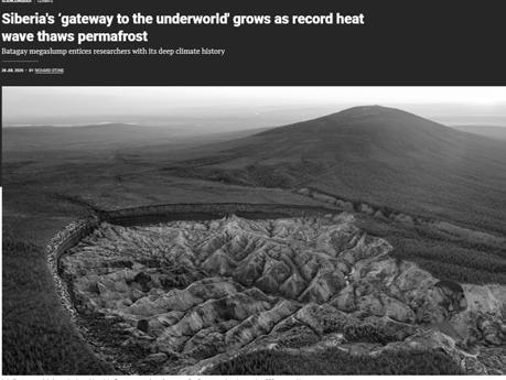
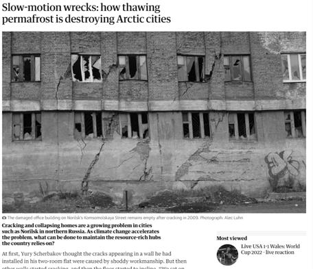
Siberia - Melting of Permafrost
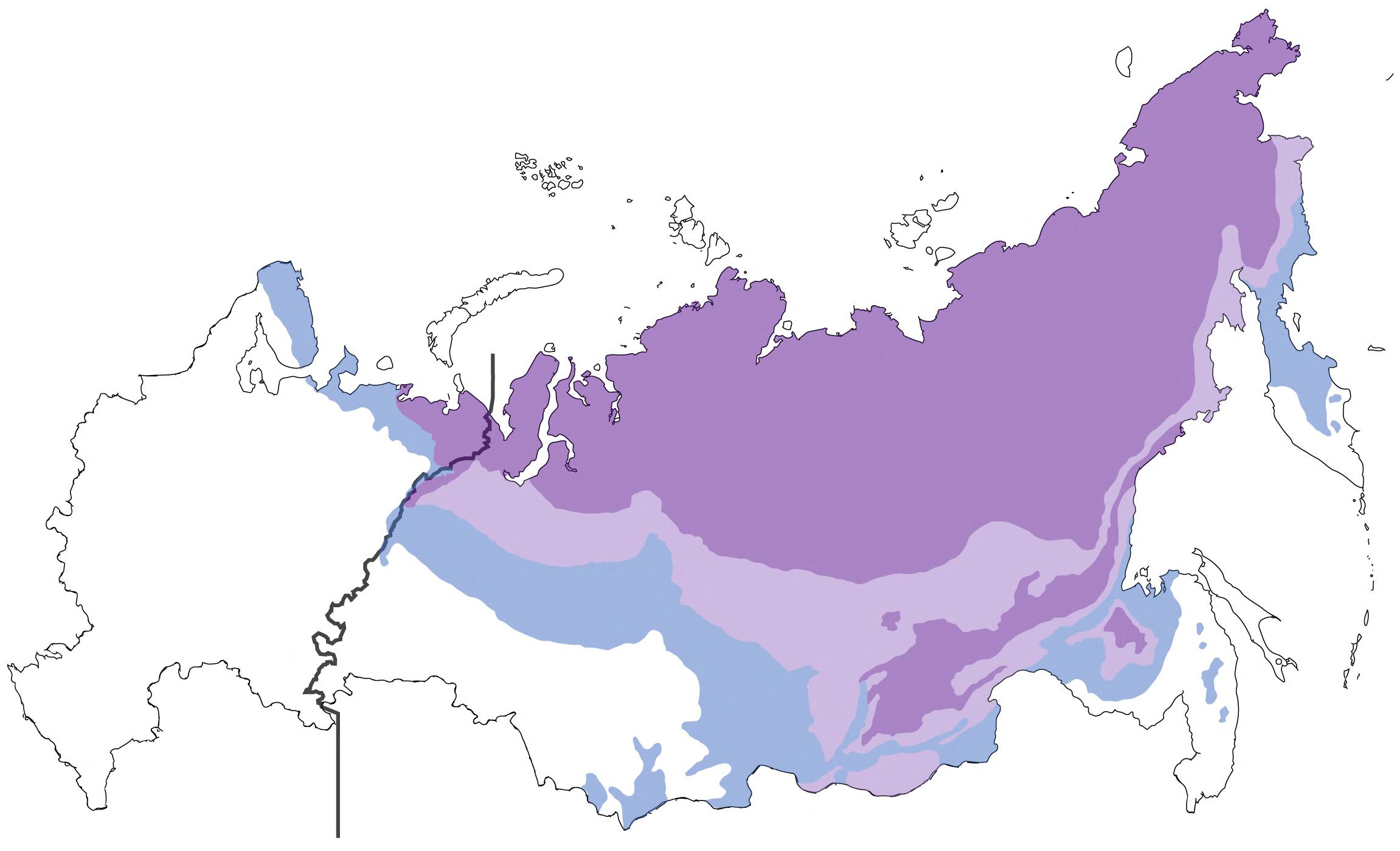
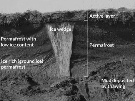
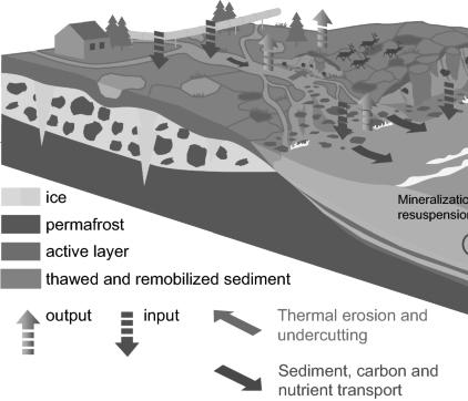
With rising global temperatures, the melting of permafrost poses a risk to Siberian infrastructure and land. Existing Soviet infrastructure is already starting to crumble, with little initiative to reinvest into the region. Local autonomy may prove as the only solution to this problem.
Siberia Surface Temperature Rise
Due to rising global temperatures, Siberia will experience vast swathes of land sinking due to the melting of permafrost.

28
NIKITA NORRIS2022-2024 SECTION 02 BARC0174ADVANCED ARCHITECTURAL DESIGN PORTFOLIO
BRIEF - PERMAFROST
RESEARCH - SIBERIAN PERMAFROST
RISK TO EXISTING INFRASTRUCTURE
EFFECTS OF PERMAFROST EROSION
RISK TO SIBERIAN LANDSCAPE
PERMAFROST GROUND BUILD UP
Isolation Strategy for Siberian Climate
Due to the harsh climate of the Siberian mountain taiga, the brief proposes a modern self-reliant mini-settlement approach.
Optimal

Delivery of Goods and Food
boat
AGRICULTURAL STRATEGY


To manage a balanced diet for cloister inhabitants, crops will be grown around the building. Fertiliser will be imported to improve the poor soil content. Annual output will consist of a summer and winter crop cycle.
Summer Crop Winter Crop
Beet Wheat
Barley Cabbage
Situated next to drinkable water, this source provides water for agriculture and day to day use. It is also used to provide cooling for permafrost.
SELF RELIANCE NIKITA NORRIS2022-2024 SECTION 02 BARC0174ADVANCED ARCHITECTURAL DESIGN PORTFOLIO PowerUnderwater River Turbines - 3 = 300kw (powers 225 homes) (all year supply) Water Drinkable water (all year supply) Gas Pipeline extension from Urengoi (all year supply) Access to Site Accessible by - Boat (small to medium) - Reindeer Water Depth Zone highlighted not accessible by
WATER SUPPLY
Carrots Peas 29
Requires extended port Site Level area Security (Fauna) Fencing required Future Expansion Adequate space / materials for settlement. Local Materials - Timber - Rock - Sand
ENVIRONMENT - ANNUAL ANALYSIS
BRIEF DEVELOPMENT
SITE
RELIANCE STRATEGY
SELF
Delivery of day to day essentials can be delivered by boat during months when the river is not frozen. Goods will be stocked for months Nov-May.
BRIEF DEVELOPMENT
SELF RELIANCE - ENERGY SOURCE
Renewable Energy Opportunity - Pur River
As part of the cloister’s self reliance strategy, a renewable energy source will be proposed. Underwater turbine technology will prove successful for the strong currents of the River Pur.
RENEWABLE ENERGY SOURCE
ENERGY INFRASTRUCTURE
Underwater Turbines
Isolated from energy infrastructure, underwater turbines will provide all energy needs for in-use operation. Annual provision is ensured due to placement at river bed (bottom of river remains liquid). Maintenance is required twice a year for the removal of flora accumulating around the cage. Three turbines will supply 37,500 kWh per month.
URENGOI GAS FIELD PROPOSED GAS PIPELINE
Generator
Yaw System
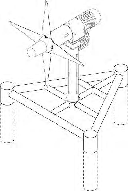

Rotor Hub
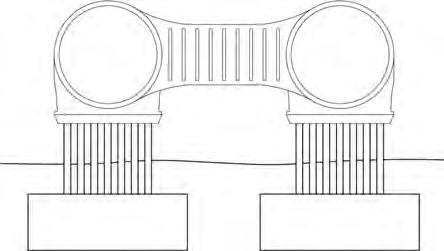
Fins
POTENTIAL IN-USE ENERGY CONSUMPTION

Proposed Gas Pipeline
Although not completely reliant on gas for operation, the proposed gas pipeline will lay ground for future expansion. Due to melting permafrost, the pipe can change height whilst remaining operational.
30
NIKITA NORRIS2022-2024 SECTION 02 BARC0174ADVANCED ARCHITECTURAL DESIGN PORTFOLIO
Cage Net (allows passage of water/stops fauna & flora passing through turbines)
Underwater cables connect turbines to building grid
Strong river current drives underwater turbines (Annual)
Triangular piles for improved stability (against current)
BRIEF DEVELOPMENT FUTURE EXPANSION PROPOSAL
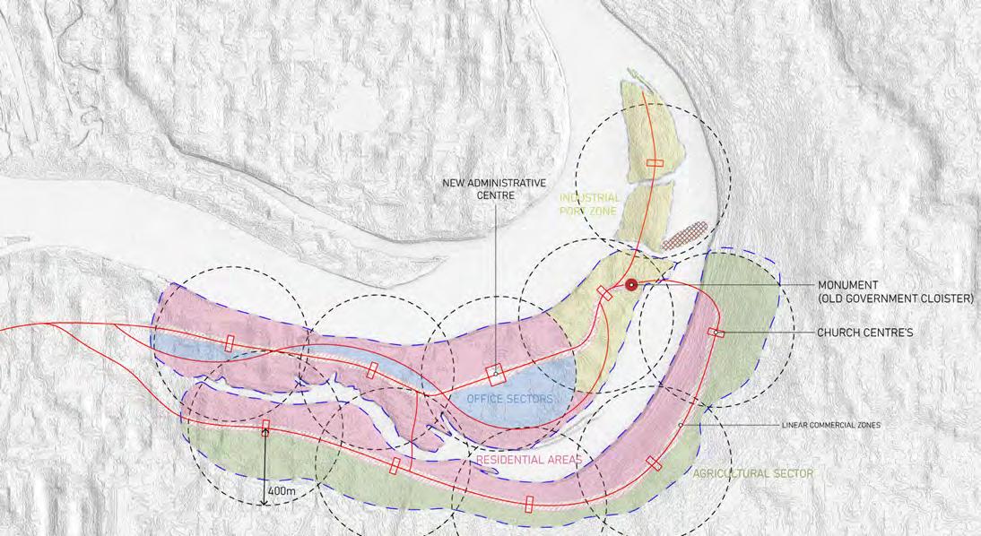
Cloister - After Use
The construction of the cloister will act as the short term strategy for the governance of Yamalo Nenets. The long term goal will be to create a new administrative settlement.
NEW SETTLEMENT PROPOSAL
CLOISTER BUILDING LIFECYCLE
Settlement has linear growth following roads and river. To be managed into districts with a church at its core.
END OF LIFE STRATEGY - STATE MONUMENT
A means to validate the identity and autonomy of a new state would be a through a legacy of architecture and culture. Yamalo Nenets may start to implement this legacy by giving the government cloister a function after its use. As the birthplace of the new state, the remnants of the cloister will become a monument to the people. Stone will be the preferred material to use at the base as it has proven to be historically durable.

31
NIKITA NORRIS2022-2024 SECTION 02 BARC0174ADVANCED ARCHITECTURAL DESIGN PORTFOLIO
Remains of plinth structure to become monument to new state and cultural centre of settlement.
New administrative cloister to be situated within office sector.
Building Construction (Year 1-7) Partial Demolition (Year 47-50) In-Use Operation (Year 7-47) After Use Function (Year 50+)
DESIGN DEVELOPMENT

03
DESIGN DEVELOPMENT
CONSTRUCTION STRATEGY PROPOSAL
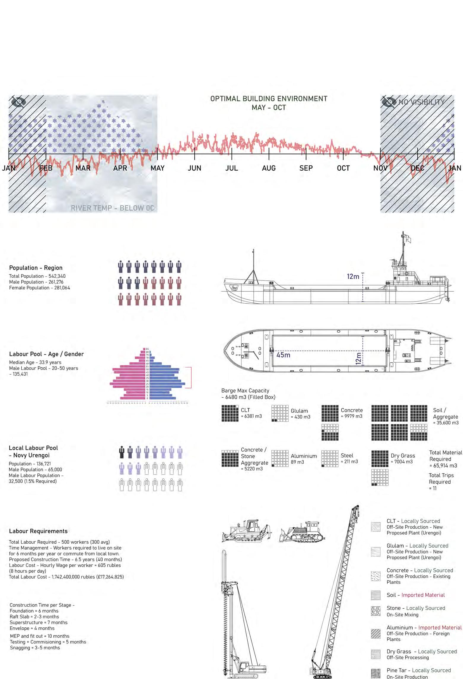
Resourcing
Although isolated from the global economy, there is a local pool of workers that will aid in the construction of the cloister. Existing heavy machinery currently used for gas fields can be transitioned to building construction.
LABOUR POOL
TRANSPORT STRATEGY
LOCAL RESOURCES
Heavy machinery can be sourced from existing port and gas field infrastructure (i.e. piling, cranes) as well as soviet era machinery within the territory.
33
NIKITA NORRIS2022-2024 SECTION 03 BARC0174ADVANCED ARCHITECTURAL DESIGN PORTFOLIO
DESIGN DEVELOPMENT
SYSTEM RESEARCH - LOCAL TIMBER


Mountain Taiga Biome
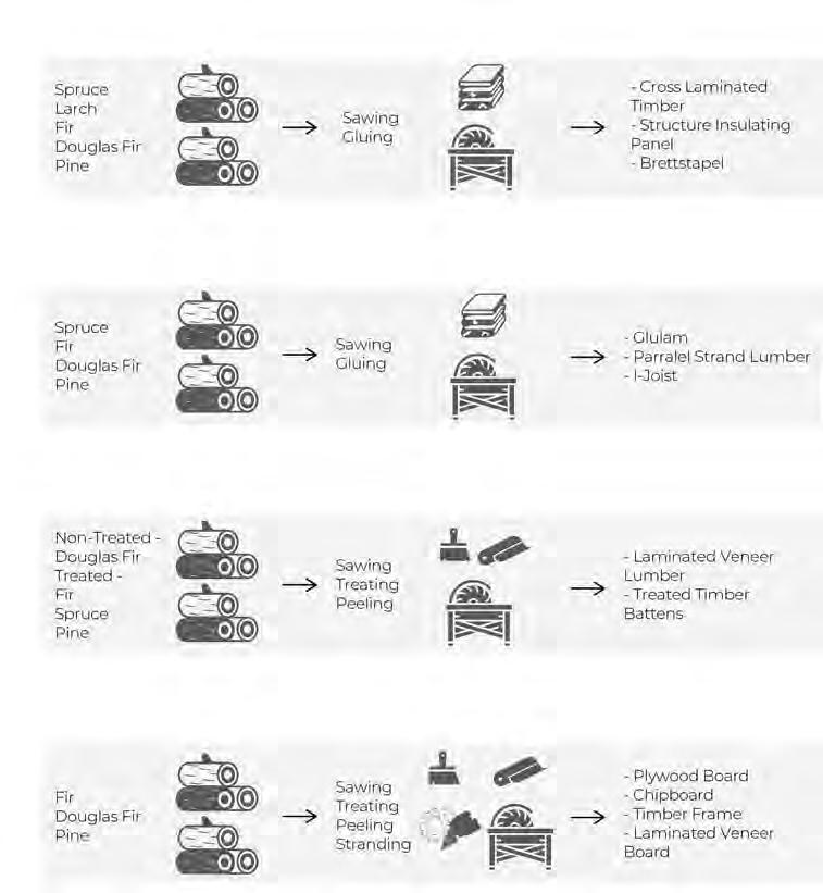
The southern part of Yamalo Nenets holds large swathes of coniferous trees. This type of timber creates great opportunity for constructing in CLT and Glulam.
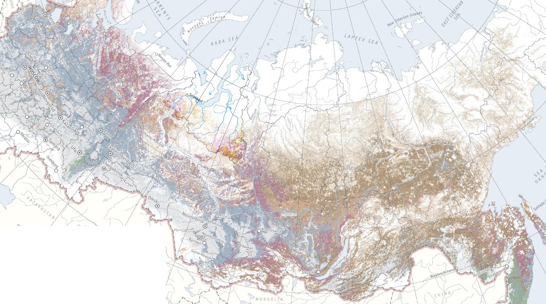
TREE SPECIES COVERAGE

YAMALO NENETS - INDIGENOUS TREES
SIBERIAN TAIGA - CONIFEROUS TREE FAMILY
TIMBER APPLICATION
Primary Structure


CONIFEROUS TREE MOISTURE CONTENT



Secondary Structure

34
NORRIS2022-2024 SECTION 03 BARC0174ADVANCED ARCHITECTURAL DESIGN PORTFOLIO
NIKITA
Spruce Tree Larch Tree Pine Tree Fir Tree
Application - CLT - Glulam - Finish - Construction Application - Joinery - External Cladding Moisture Content - 35% Moisture Content - 12% Moisture Content - 12% Moisture Content - 24% Application - Furniture - Cabinetry - Frames - CLT Application - Beams - Furniture - Cladding - Flooring
Cladding Fit-Out
DESIGN
Material Research
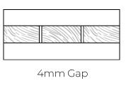
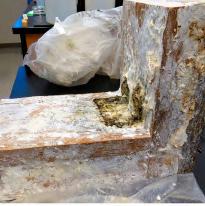
To improve unwanted attributes of CLT construction, super heated steamed treated CLT and edge gluing will improve the longevity of the material during building use.

IMPROVING MATERIAL PERFORMANCE
Improving Moisture De-laminationOption Exploration


Fabrication of CLT panels will include additional improvements such as SHST timber on the outer layer of CLT panels.


Improving Shear ForcesOption Exploration
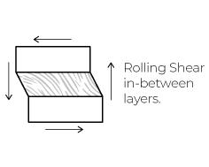


Edge gluing provides the best method of resisting shear forces in CLT, an attribute that will greatly benefit constructing in timber.


35
CLT SECTION 03 BARC0174ADVANCED ARCHITECTURAL DESIGN PORTFOLIO NIKITA NORRIS2022-2024
DEVELOPMENT SYSTEM RESEARCH -
CLT MANUFACTURE PROCESS
1. Tree Sourcing
6. Planing Lamination
2. Cutting and Planing
7. Adhesive Application
3. Controlled Drying
8. Assembly
4. Strength Grading
4. Pressing and Curing
5. Finger Joining
5. Finishing and Packaging
DESIGN DEVELOPMENT
SYSTEM PROPOSAL - SLOTTED
System Parameters

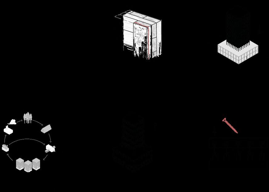
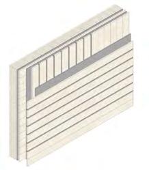
This page delves into the many benefits CLT construction brings, as well as the necessary strategies in ensuring its longevity.
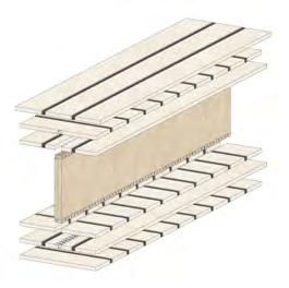
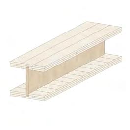

36
BENEFITS
SYSTEM DISADVANTAGES
SYSTEM
SOLUTION TO
CLT SECTION 03 BARC0174ADVANCED ARCHITECTURAL DESIGN PORTFOLIO NIKITA NORRIS2022-2024 Fire Properties Sustainable Material Seismic Durability Fast On-site Construction Material Reduction Weight Reduction Moisture Protection - Concrete Stone Aggregate Plinth Moisture Protection - Pine Tar Coated Shingles Specialised Construction - Off-site Factory Solid CLT Panel Build up 35x200mm SHST CLT Timber 35x200mm KD CLT Timber PUR1 CLT Glue CLT Slotted Plate System Build up 2 3 1 1
DESIGN DEVELOPMENT

SYSTEM OPPORTUNITY - MEGA SHINGLE
Mega Shingle Benefits
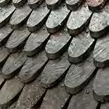
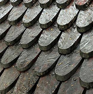
Taking cultural inspiration from existing forms in Russian orthodox design, an upscaling of the timber shingle can provide additional insulation to the cloister within a cold environment.

Shingle PrecedentOrthodox Church
The unique form of orthodox roof shingles in Russia can be used to provide a cultural identity to the cloister.

SNOW
Material Opportunity - Pine Tar

(Traditional Manufacture)
Smoke Escape Funnel


Earth, Wood Bark Layering
Pine Wood
Pine Tar Pipe
Pine Wood Carbonisation
By Product - Pine Tar
37
NIKITA NORRIS2022-2024 SECTION 03 BARC0174ADVANCED ARCHITECTURAL DESIGN PORTFOLIO
Increased moisture protection Larger panels have ability to be recycled into more components Shovels can be installed to collect snow
Size Increase Benefits
PROPOSAL
MEGA SHINGLE
1 Option 2Chosen
SHOVEL STRATEGY Option
DESIGN DEVELOPMENT
FORM REFERENCE - 1A
Government Building Typology
Existing administrative buildings will inform the programme of the cloister.
Orthodox Churches
1. Tokyo Metropolitan Parliament Building (Japan)

2. Beehive Parliament Building (New Zealand)
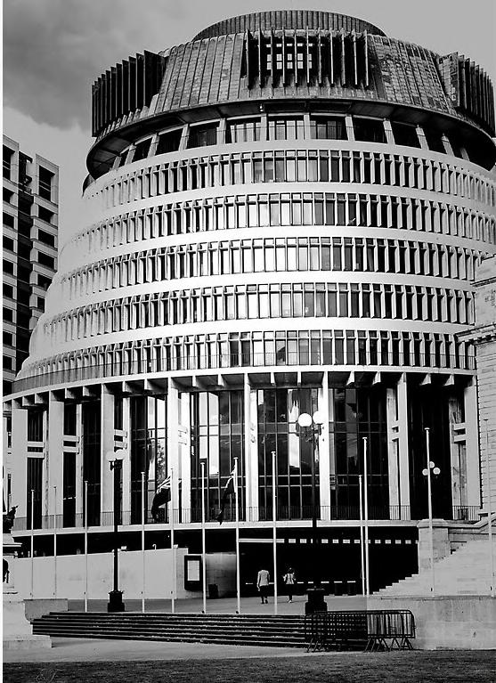
3. US Capitol Parliament Building (Washington DC)

38
SECTION 03 BARC0174ADVANCED ARCHITECTURAL DESIGN
NIKITA NORRIS2022-2024
PORTFOLIO
1.
2.
3.
2.
3.
DESIGN DEVELOPMENT
FORM REFERENCE - 1B
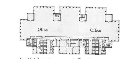
Tokyo Metropolitan Parliament Building - Public / Private Domain
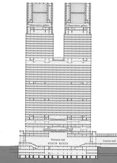

The parliament building shows a distinctive separation of private/public domains within its form.
Public / Private Domain Separation
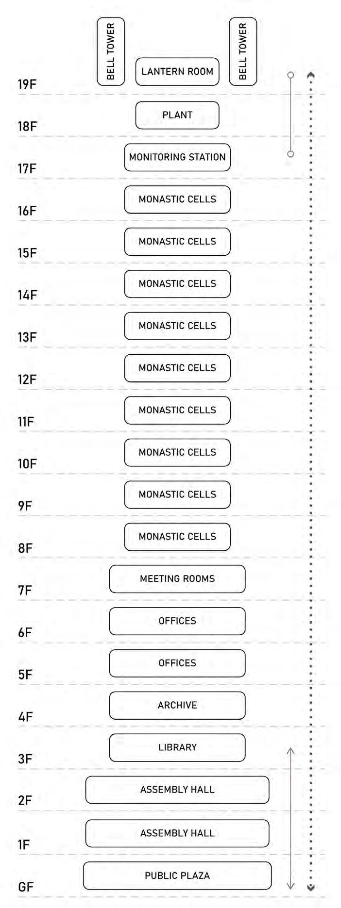
While public spaces are situated at the bottom of the building where access is easier, private spaces are situated in the upper parts of the building, where access is limited.

39
NIKITA NORRIS2022-2024 SECTION 03 BARC0174ADVANCED ARCHITECTURAL DESIGN PORTFOLIO
Building Programme 1 - Entrance Hall 2 - Assembly Building 3 - Citizen’s Plaza 4 - Tower 1 5 - Tower 2 6 - Office Space 7 - Lobby 8 - Conference Hall 9 - Observation Gallery 10 - Road Access
ISOMETRIC - NORTH EAST PROJECTION
Fifth Floor Plan Twenty Third Floor Plan Super Block Section 1. 2. 3. 4. 4. 9. 10. 9. 5. 5. 6. 6. 6. 6. 1. 7. 7. 8. 8. Public Access Private Access
DESIGN DEVELOPMENT
Russian Orthodox Church Typology
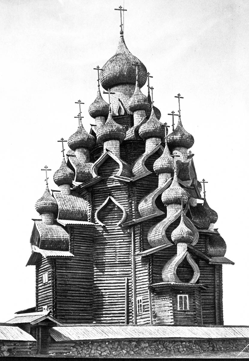
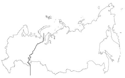
Existing Russian Orthodox churches will inform the programme of the cloister.
Orthodox Churches
1. Church of Transfiguration (Kizhi Pogost)
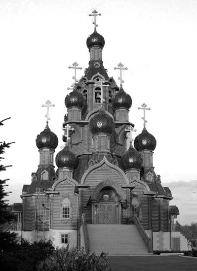
2. Church of the Nativity of St. Jon the Baptist (St. Petersburg)
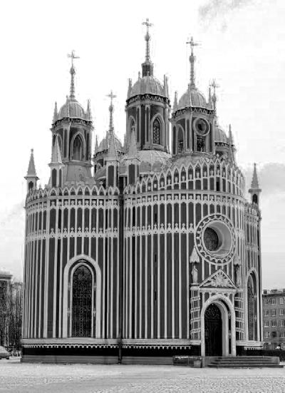
3. Transfiguration Church (Star City)
1.
40
SECTION 03 BARC0174ADVANCED ARCHITECTURAL DESIGN PORTFOLIO NIKITA NORRIS2022-2024
FORM REFERENCE - 2A
1.
2.
3.
3.
DESIGN DEVELOPMENT
Church of Transfiguration - Holistic Building Form
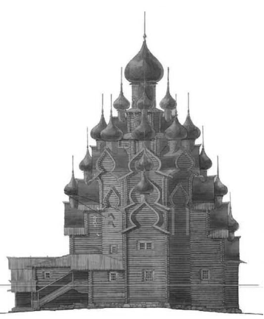
The church shows a distinctive response to its surrounding environment, opting for a monolithic form that retains heat better during colder months.
Thermal Opportunity - Form Factor
Although adorned with many domes, the Church of Transfiguration maintains a regular profile in elevation and plan. This may due to the need of retaining heat in colder months. This strategy will prove useful for the design of the cloister.
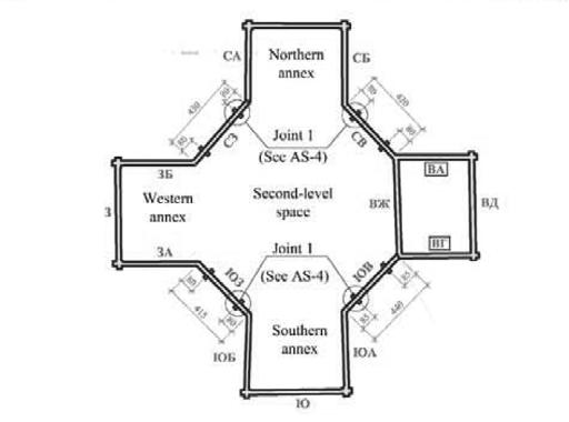
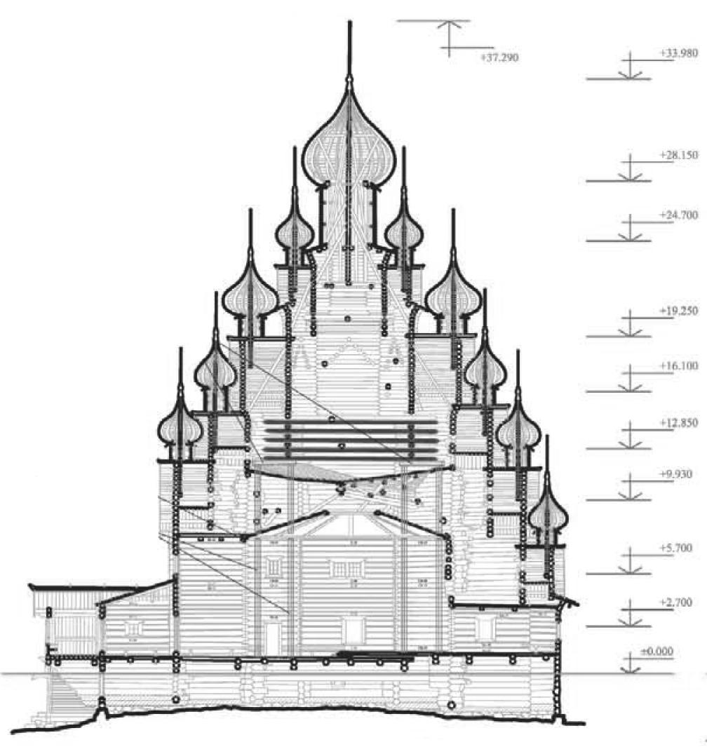
41
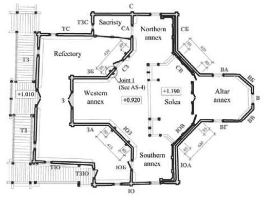
2B NIKITA NORRIS2022-2024 SECTION 03 BARC0174ADVANCED ARCHITECTURAL DESIGN PORTFOLIO SECTION SIDE ELEVATION GROUND FLOOR PLAN
FLOOR PLAN
FORM REFERENCE -
SECOND
Building Programme 1 - Refectory 2 - Sacristy 3 - Western Annex 4 - Northern Annex 5 - Southern Annex 6 - Solea 7 - Altar Annex 8 - Entrance 1. 2. 3. 4. 4. 5. 5. 6. 7. 7. 1. 8. 8. 7. 3. 4. 6. 3.

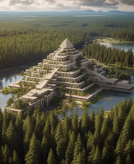
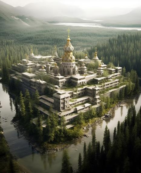
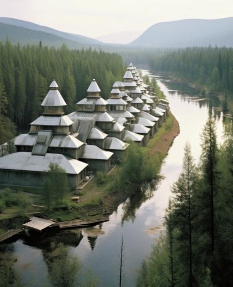


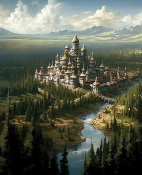
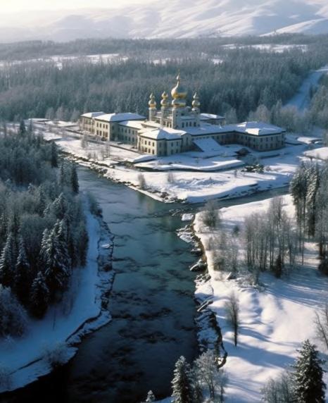
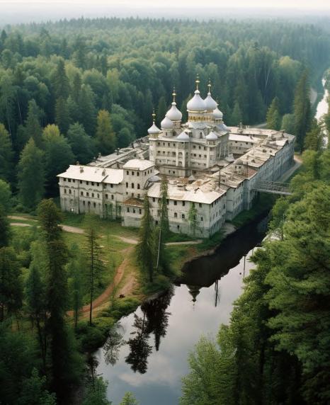
42 SECTION 03 BARC0174ADVANCED ARCHITECTURAL DESIGN PORTFOLIO NIKITA NORRIS2022-2024 Midjourney Concepts DESIGN DEVELOPMENT FORM INSPIRATION
DESIGN DEVELOPMENT
FORM EXPERIMENTATION - 1
Monastery Typology

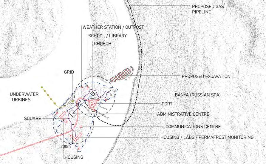
Taking inspiration from existing cloister forms, a collection of buildings is proposed for the peninsula. Each building will serve a different function for the complex i.e. church, assembly, monitoring etc.
GENERAL ARRANGEMENT PROPOSAL
Massing - System Integration
Initial Massing
Perimeter Staircores (Open Interior)


Tapered Profile (Snow Loads)
Slotted Plate System Integration
Novodevichy Convent

43
SECTION 03 BARC0174ADVANCED ARCHITECTURAL DESIGN PORTFOLIO NIKITA NORRIS2022-2024
SITE PLAN - PROGRAMME PROPOSAL
Valdai Convent
DESIGN DEVELOPMENT
FORM EXPERIMENTATION - 2A
Low Rise - Single Building Typology
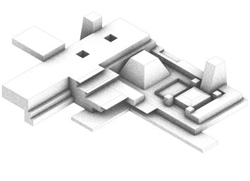
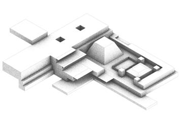
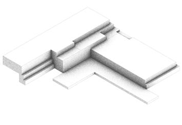
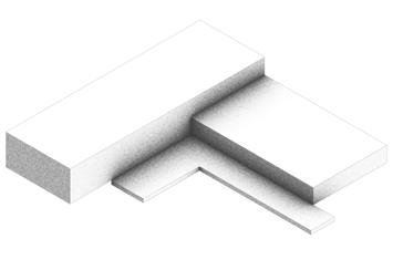
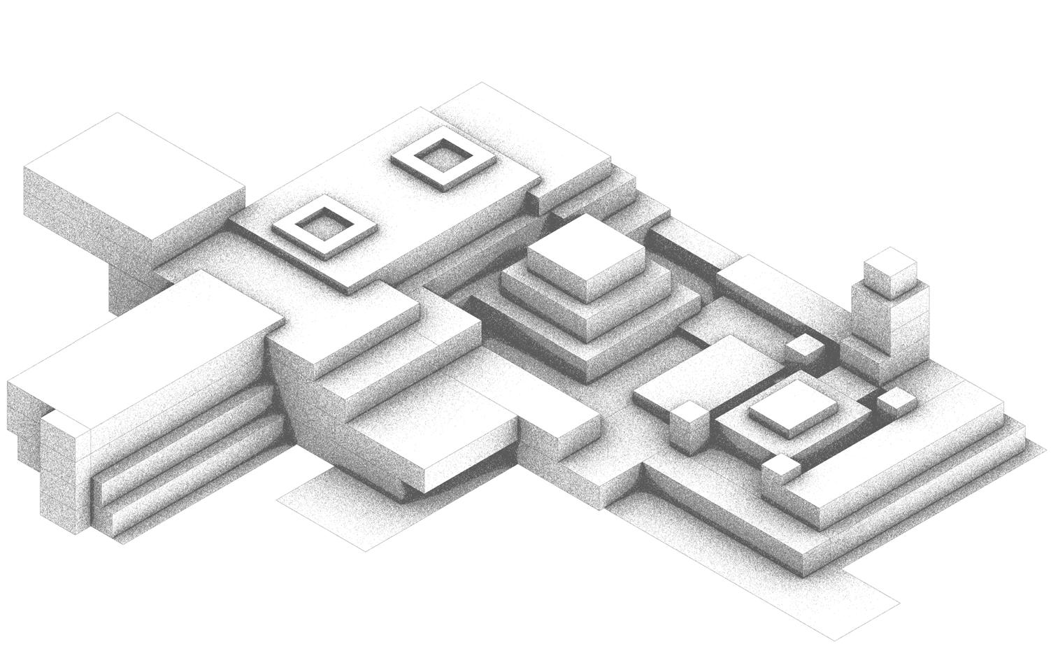
Taking into account the need to retain heat in a cold climate, cloister functions will be condensed into a single building. This will also improve the human comfort levels for occupants.
ISOMETRIC MASSING
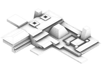
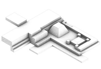


MASSING GENESIS
44
NIKITA NORRIS2022-2024 SECTION 03 BARC0174ADVANCED ARCHITECTURAL DESIGN PORTFOLIO
Stage 1 Initial Massing
Stage 5 External Canopies
Stage 2 Topographical Response
Stage 6 Light Shaft & Skylights
Stage 3 Private/Public Access
Stage 7 Security & Bell Tower
Stage 4 Assembly Hall/Church Program
Stage 8 Environmental Treatment - Roofs
DESIGN DEVELOPMENT
FORM EXPERIMENTATION - 2B
Low Rise - L-Shaped Form
This page considers an L-shaped form for the cloister. This provides the option for expanding the cloister into other sections. The programme of the assembly hall and the church are clearly defined by their height.
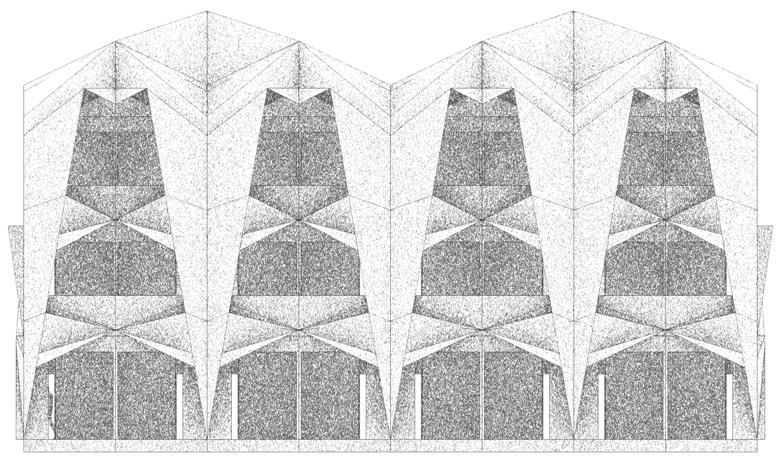
ISOMETRIC STUDY
ISOMETRIC-2F
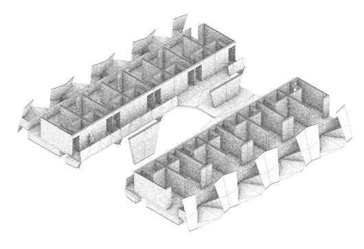
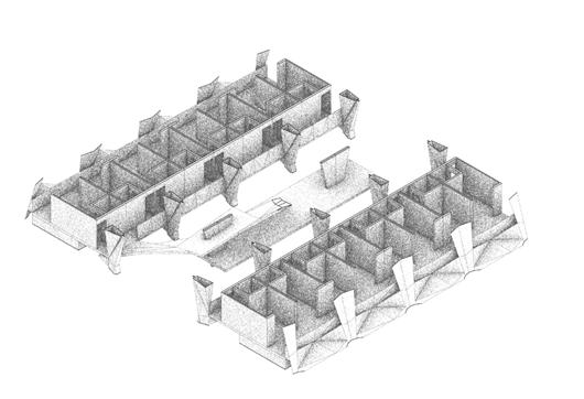
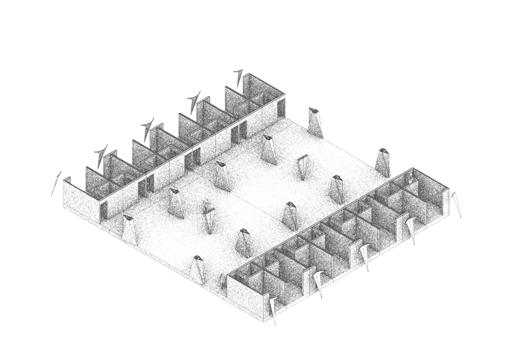

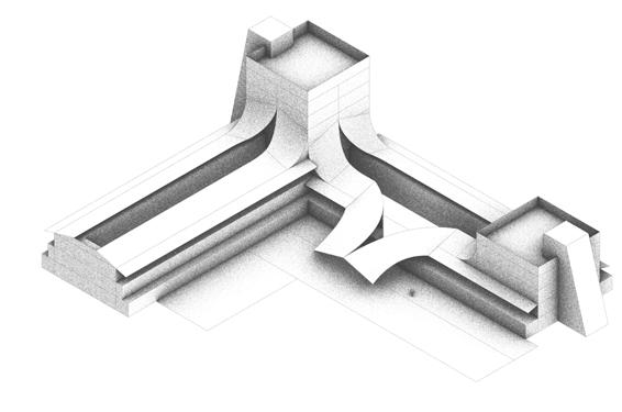
Linear Arrangement
A linear arrangement has been chosen for clergy accommodation due to the brief requirement of providing access to fresh air and views of the surrounding area.
ISOMETRIC-1F
ISOMETRIC-GF
45
SECTION 03 BARC0174ADVANCED ARCHITECTURAL DESIGN PORTFOLIO NIKITA NORRIS2022-2024
DESIGN DEVELOPMENT
FORM EXPERIMENTATION - 3A
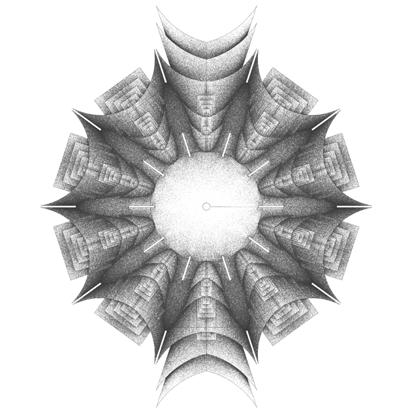
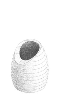
Tower Typology - Stand-alone
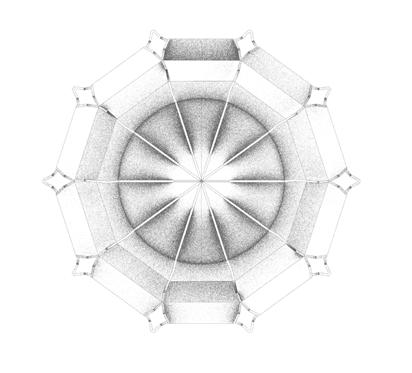
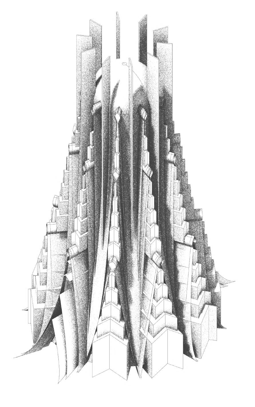
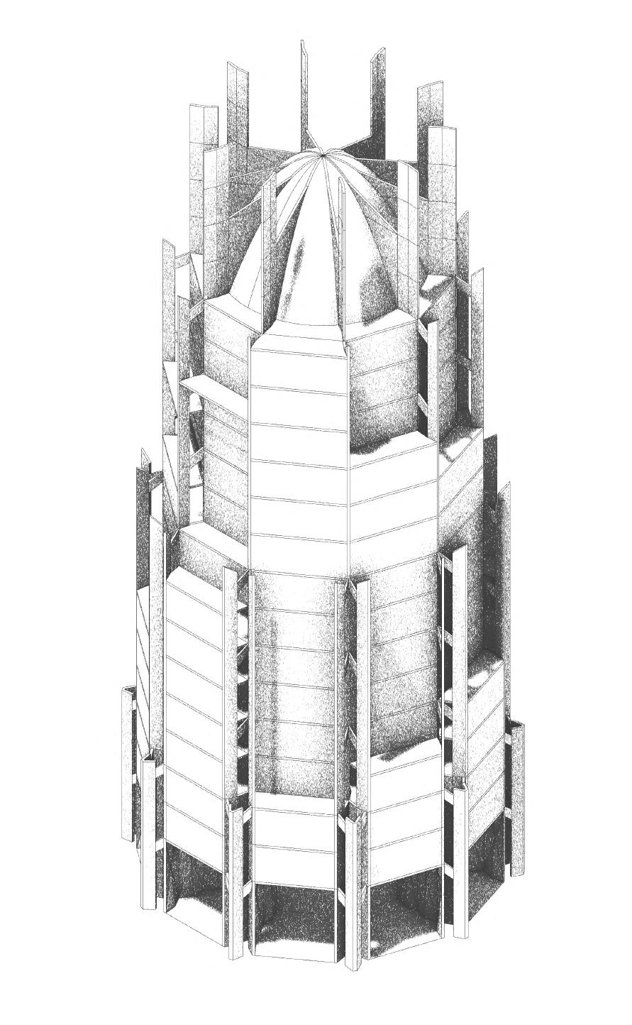

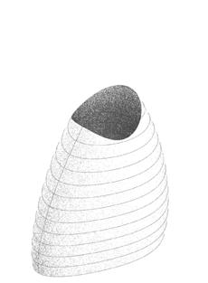
This page explores the feasibility of a radical change in form, opting for high rise construction as opposed to low rise.
Modular construction will greatly benefit building lead times. However, it may reduce the identity of function as a unique building typology.
Taking greater inspiration from Russian Orthodox ornamentation, this design may prove unfeasable in structural integrity and delivery.
46
NIKITA NORRIS2022-2024 SECTION 03 BARC0174ADVANCED ARCHITECTURAL DESIGN PORTFOLIO
Experiment 1 - Modular Tower
Experiment 2 - Tapered Tower
Study 1 Study 2 Study 3Chosen Massing
DESIGN DEVELOPMENT
FORM EXPERIMENTATION - 3B
Tower Typology - Tower/Base

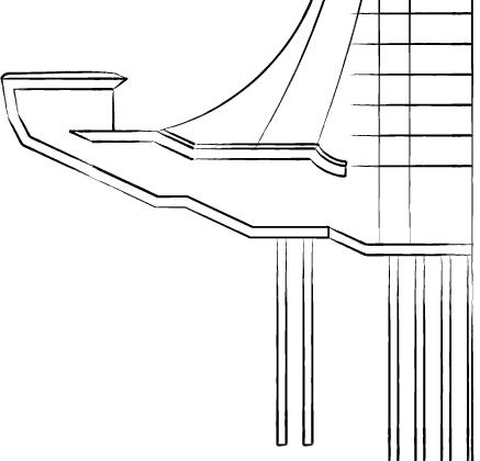

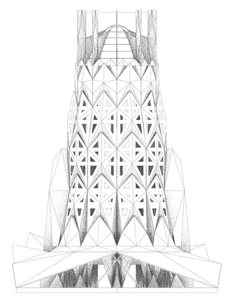


Responding to the combined programme of the government cloister, an integrated base for the tower will define the distinction between private and public realms. This will also prove useful for the building’s structure.
EXPERIMENT - INTEGRATED
CONCRETE BASE STUDY - ENVIRONMENTAL BENEFITS
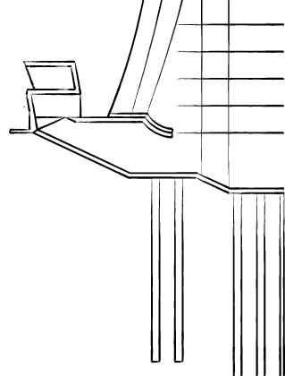
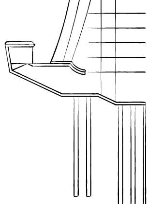
Constructing a base
will provide ample moisture protection for a CLT constructed tower. Raised platforms will also add protection against dangerous wildlife.
47
SECTION 03 BARC0174ADVANCED ARCHITECTURAL DESIGN PORTFOLIO NIKITA NORRIS2022-2024
made from concrete and stone
1. - Raised Viewing Platform
3. - Single Storey Narrow Platform
2. - Single Storey Wide Platform
2. - Double Storey Wide Platform
1. - Sectional Isometric Study
TIMBER BASE/TOWER
DESIGN DEVELOPMENT
FORM EXPERIMENTATION - 3C
Chosen Form - Petal Tower/Base
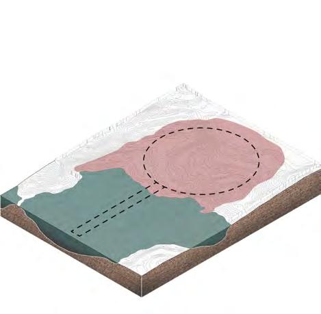
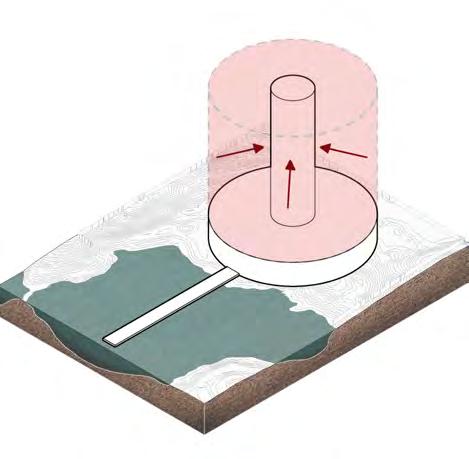
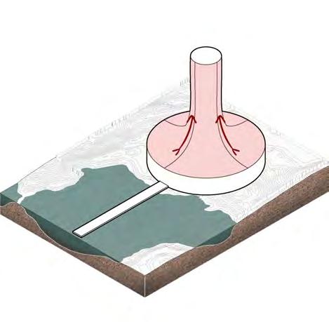
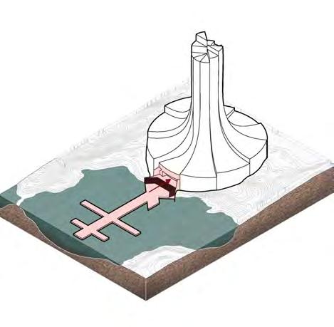
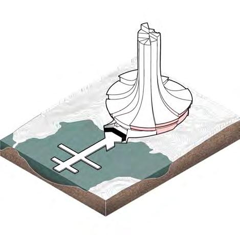
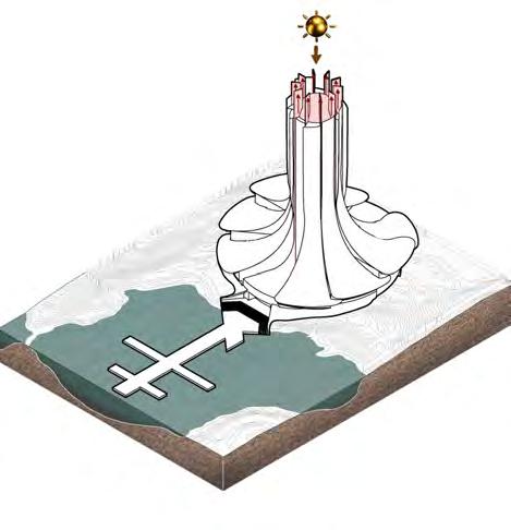
Taking inspiration from the sloping hills of the Siberian mountain taiga, the tower’s form will be divided into eight sloping petals. The petals will act as both the envelope of the tower and the base, providing great opportunity for heat retention and structural integrity.


SITE PLAN - INITIAL ARRANGEMENT

Plan Arrangement
The tower will be situated next to the bay, providing easy access to water for goods/ human access by boat. The plan points to a radial arrangement (administrative typology) that defines the main functions of the government cloister (Assembly Hall/Church).

TOWER FORM / PROFILE ARRANGEMENT STUDIES
Isometric Fragment Study
Elevation Fragment Study
Sectional Study
48
NIKITA NORRIS2022-2024 SECTION 03 BARC0174ADVANCED ARCHITECTURAL DESIGN PORTFOLIO



49
BUILDING GENESIS 02. Massing Opportunity - One holistic form reflects combined building typology 05. Topographical Treatment - Separation into petals reflect height change of topography 08. Illuminance / Atrium Design
Atrium beneficial for central light source and stack ventilation strategy - Glazing for main entrance and gardens reflects program requirements - Petal fins let light in from the side. 03. Tower / Base Typology - Separation of hierarchy created through visual form 06. Riverside Access
Raised access from port prevents risk of flooding - Clear distinction of main building entrance (linear arrangement of port) 09. Capping Treatment
Aesthetic qualities
church cloister typology - Housing
lantern creates internal/external light source during dark months 01. Topographical Feasibility - Area of flat ground chosen - Adjacency to water (port) 04. Thermal Strategy - Low Form Factor - Masses merged to improve building form factor - Wider base improves structure of tower 07. Fauna Security Strategy - Raised platform to deter wildlife - Main building functions located above ground floor SECTION 03 BARC0174ADVANCED ARCHITECTURAL DESIGN PORTFOLIO NIKITA NORRIS2022-2024
Design Considerations DESIGN DEVELOPMENT
-
-
-
of
of
DESIGN DEVELOPMENT
SPATIAL
ARRANGEMENT - PLAN
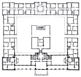
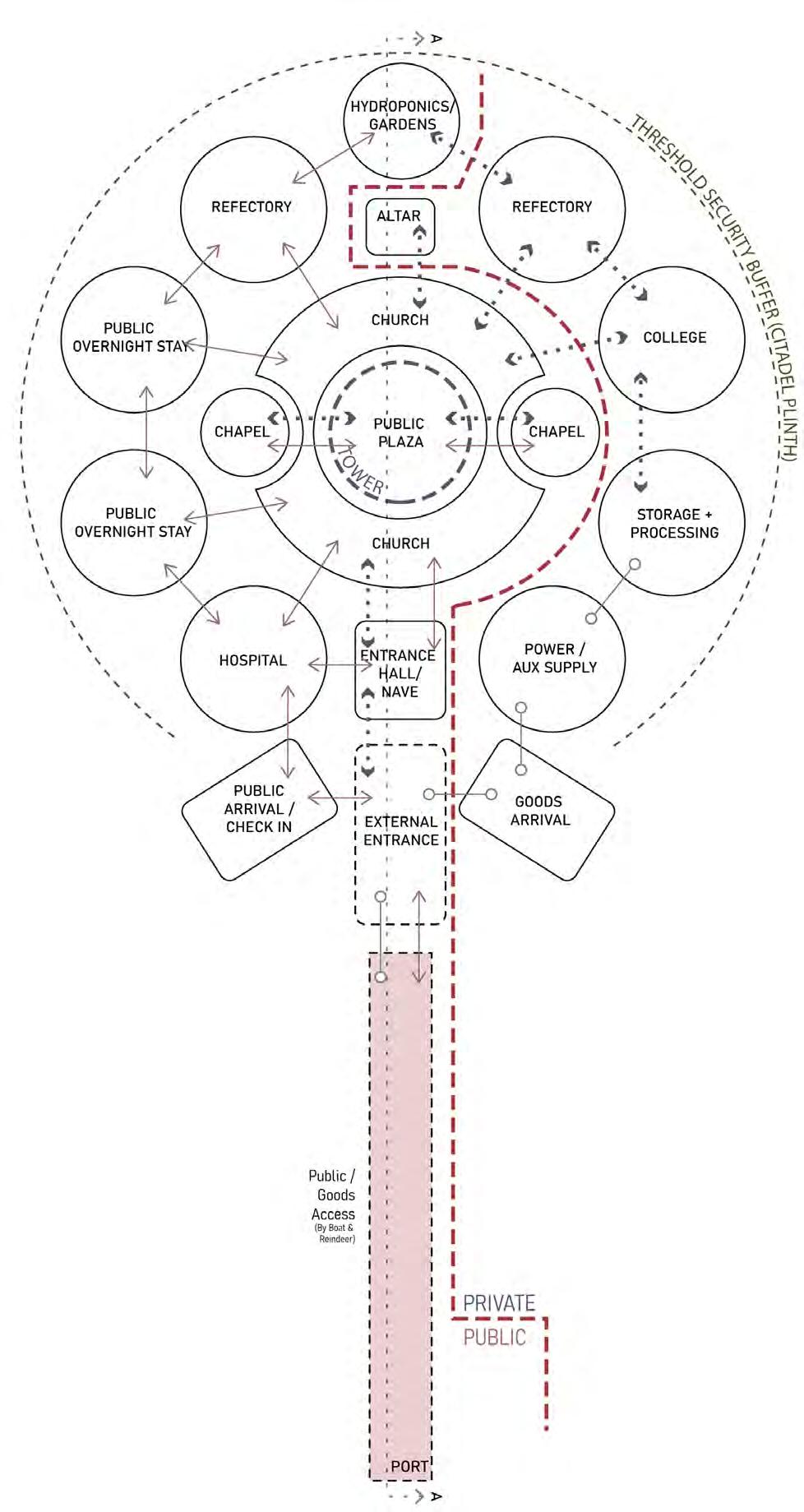
Combined Typology - Administrative Influence
This page shows the design intent of the government cloister, driven by existing considerations in an administrative typology. This will be merged with religious design to create a new typology.

PRECEDENT - ADMINISTRATIVE BUILDING
Analysis of existing administrative buildings show a low rise, radial arrangement, with areas of greatest importance situated within the centre of the plan i.e. Public Plaza.

Queensland Parliament Building
Radial Hierarchy
Tokyo Metropolitan Government Building
PROGRAM ARRANGEMENT
PROPOSAL - Fused Central Layout
50
Plaza / Assembly Church NIKITA NORRIS2022-2024 SECTION 03 BARC0174ADVANCED ARCHITECTURAL DESIGN PORTFOLIO
Radial Hierarchy
central space Difference in plan on one side defines entrance Circulation provides quick access to centre Circulation provides quick access to centre
Auxiliary functions surround central space Auxiliary functions surround
DESIGN DEVELOPMENT
Combined Typology - Religious Influence
This page shows the design intent of the government cloister, driven by existing considerations in a religious typology. This will be merged with administrative design to create a new typology.

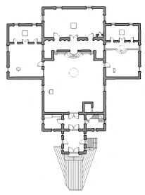
PRECEDENT - ORTHODOX CHURCH
Analysis of existing orthodox churches show a stringent hierarchy of space, separating the public domain from the private the further it goes into the church.
Holy Ascension Russian Orthodox Church
Altar holds greatest importance at back of church (separated from public domain)
Church has hierarchical linear arrangement, growing increasingly private towards the altar
Controlled access to spaces throughout plan
Nativity of Christ Orthodox Church
Altar holds greatest importance at back of church (separated from public domain)
Church has hierarchical linear arrangement, growing increasingly private towards the altar
Controlled access to spaces throughout plan

PROGRAM ARRANGEMENT
PROPOSAL - Vertical Hierarchy
51
SPATIAL
SECTION SECTION 03 BARC0174ADVANCED ARCHITECTURAL DESIGN PORTFOLIO NIKITA NORRIS2022-2024
ARRANGEMENT -
Private Public
DESIGN DEVELOPMENT
MATERIAL PROPOSALS

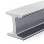
Local Resources

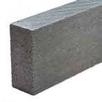
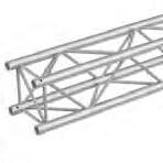
The materiality of the tower has been greatly influenced by the materials that are locally available. This includes resources such as timber, sand, stone, grass and gravel.


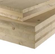
MATERIAL FRAGMENT PROPOSAL
MATERIAL PALETTE
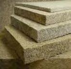
The materiality of the building is influenced by materials local to site or to the region of Yamalo Nenets. This includes timber, stone, clay, limestone, grass that can be manufactured into CLT, glulam, concrete and insulation. Harder materials to source such as steel and aluminium will be used in smaller quantities.

52
NIKITA NORRIS2022-2024 SECTION 03 BARC0174ADVANCED ARCHITECTURAL DESIGN PORTFOLIO
CLT Panels
Glulam Beams
Steel Beams
Steel Trusses Dry Grass Insulation
Aluminium Frame System
Charred Timber Cladding Pine Tar Coating
Concrete/Stone Aggregate Concrete Foundation
Concrete/Stone Aggregate Concrete Charred Wood Cladding Dry Grass Insulation Glulam Beam Pine Tar Coated CLT Panel CLT Panel Steel Beam Aluminium Frame Steel Truss

04 DETAILED
DESIGN
Assembly
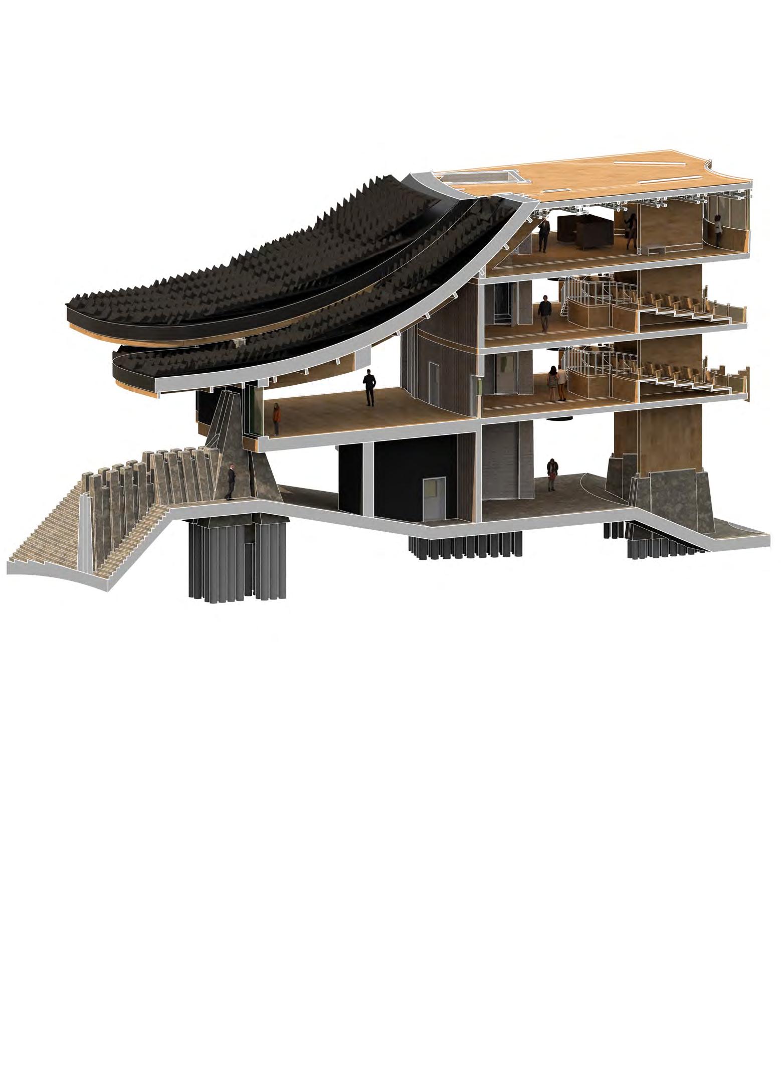
Sectional isometric depicting composition of building elements and its relationship to building hierarchy.




54
SECTION 04 BARC0174ADVANCED ARCHITECTURAL DESIGN PORTFOLIO NIKITA NORRIS2022-2024
SPATIAL HIERARCHY
ENVELOPE BUILD UP
EXTERNAL MEGA SHINGLE ROOF BUILD UP
ENTRANCE HALL (PUBLIC)
CHURCH/PUBLIC PLAZA/CIRCULATION (PUBLIC)
PUBLIC OVERNIGHT STAY/CIRCULATION (PUBLIC) D. ASSEMBLY HALL/ LOUNGE (PUBLIC/ PRIVATE)
OFFICES/MEETING ROOMS (PRIVATE) F. MONASTIC CELLS (PRIVATE) 2. EXTERNAL PARTITION BUILD UP 3. EXTERNAL FLOOR BUILD UP 315x150mm Glulam Beam (45mm) 110x75mm CLT Panel (Slotted Connection) 12.5x110mm Timber Decking 110x75mm CLT Panel (Slotted Connection) 110x50mm CLT Panel (Slotted Connection) Integrated Servicing (3mm protective membrane) Dry Grass Insulation (400mm) Dry Grass Insulation (400mm) 110x75mm CLT Panel (Slotted Connection) 110x85mm CLT Panel (Slotted Connection) Weatherproof Membrane (2mm) Weatherproof Membrane (2mm) 110x50mm CLT Panel (Slotted Connection) 8000x2000mm Mega Shingle Panel (Slotted Connection) 40x120mm Charred Timber Cladding Batten Weatherproof Membrane (2mm) 330mm (Depth) Snow Shovel (Slotted Connection) 110x150mm Glulam Beam (45mm) 40 mm CLT Shingle Slot 60x40mm Timber Cladding Support Rail Batten 110x85mm CLT Panel (Slotted Connection) 110x50mm CLT Panel (Slotted Connection) 110x85mm CLT Panel (Slotted Connection) Dry Grass Insulation (400mm) A B D E F C
DETAILED DESIGN SECTIONAL STUDY
VERTICAL
BUILDING
1.
A.
B.
C.
E.
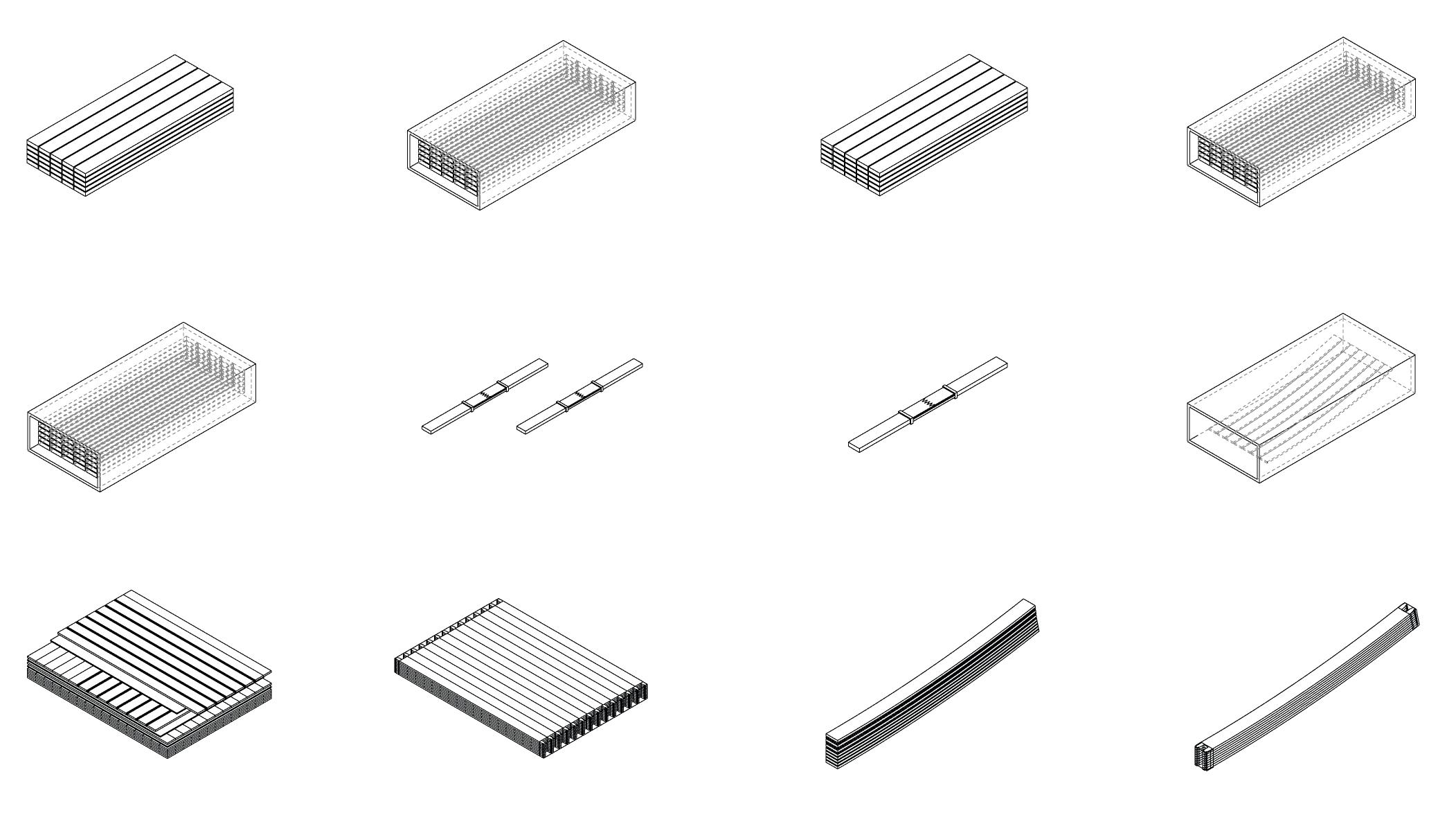
DETAILED DESIGN TIMBER FABRICATION
CLT & Glulam
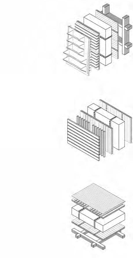
This page defines the process and strategy in constructing CLT / Glulam prefabricated elements.
Cross Laminated Timber Structure - Fabrication Process
Glulam Timber StructureFabrication Process
A - Super Steam Heated Treatment B - Kiln Drying C - CNCC D - Steam Bending E- Edge Gluing F - Gluing
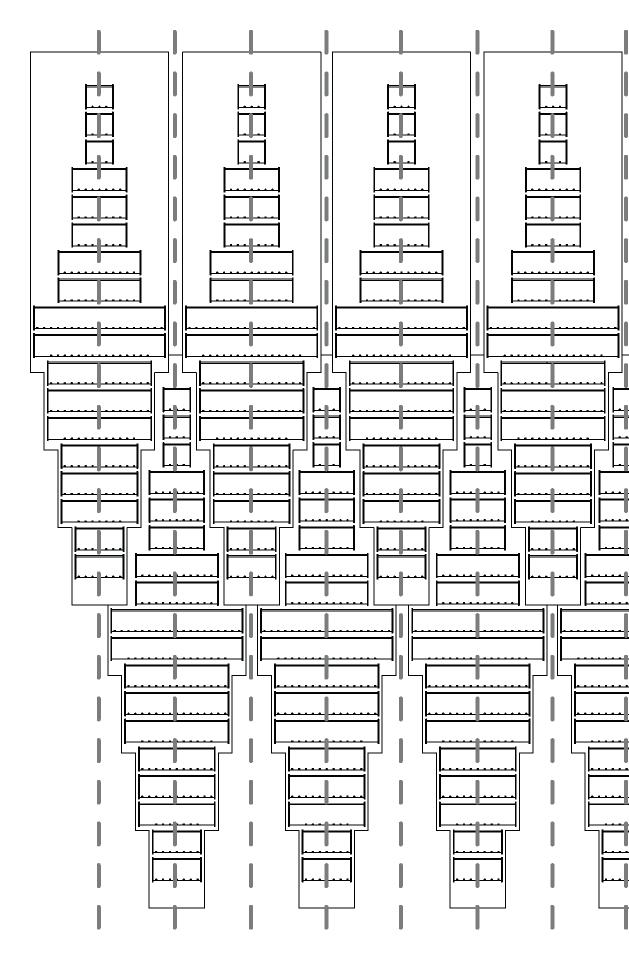
CLT/GLULAM REPETITION
CNCC Machine (CLT/Glulam Fabrication)
Although the variation in profile, there are repeatable components within the design of the building. These duplications can aid in a more efficient work-flow and reduce production time in off-site fabrication. This allows for a faster lead time in delivery of finished components.
Refer to diagram (3.)
Steam-bending Machine (Glulam Fabrication) (SB)

(Per
Floor plates will vary in size due to varying envelope/atrium dimensions. However components within the floor plate can be repeated as shown by the diagram above.

55
NIKITA NORRIS2022-2024 SECTION 04 BARC0174ADVANCED ARCHITECTURAL DESIGN PORTFOLIO
1. Delivery and cutting.
1. Delivery and cutting.
3. Selection of timber kiln dried.
3. Finger Jointing.
5. Assembly and adhesive application.
5. Assembly and adhesive application.
2. Selection of timber super steam heated.
2. Timber kiln dried.
A F F F C C B B D E C C
4. Finger Jointing.
4. Timber steamed and bent into shape
6. Dove joints cut.
6. Dove joints cut.
1. x 10 11. x 8 21. x 6 2. x 10 12. x 8 22. x 4 No Duplication 3.
13. x 8 4. x 19 14. x 8 5. x
15. x 8 6. x 8 16. x 16 7. x 8 17. x 10 8. x (8x10) 18. x 16 9. x 8 19. x 6 10. x 8 20. x 2
(19x10)
3. Floor Plate Repeatability
Floor)
1. 2. 3. 4. 5. 6. 7. 8. 9. 10. 11. 12. 13. 14. 15. 16. 17. 18. 19. 20. 21. 22.
DETAILED DESIGN
TIMBER FABRICATION
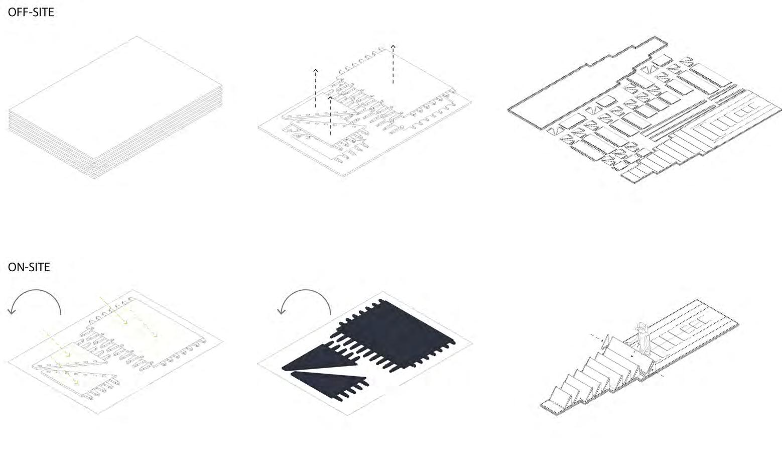
Mega Shingle Fabrication
Process of mega shingle construction, using a combination of modern and traditional methods. Special consideration is taken due to shingle size.
PINE TAR MEGA SHINGLE FABRICATION
Pine Tar Coating
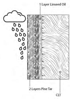
Pine tar creates an impermeable layer that resists moisture (rain/snow). The coating will need to be re-applied every 2-3 years.
MEGA SHINGLE APPLICATION
SHINGLE TYPE PROFILES


8m Panel
IN-SITU SHINGLE PLACEMENT

Passive Gutter
Strategy
Application of snow shovels may degrade the coating. To mitigate this, curved panels guide water to holes at the bottom.
Vertical Application
The larger panel will be applied to vertical areas of the building envelope.
8m Panel
4m Panel
Vertical-Horizontal Application
As the building envelope begins to flatten towards the building threshold, smaller panels will be applied to allow for the increase in curvature.

56
SECTION 04 BARC0174ADVANCED ARCHITECTURAL DESIGN PORTFOLIO NIKITA NORRIS2022-2024
1. Prepared CLT panels delivered
4. Panels laid out to dry at site (both sides)
3. Shingles sorted, packed and shipped to site
6. Shingle assembled by hand
2. Shingle panels cut using CNCC
5. Pine tar coating applied to panels (both sides)
DETAILED DESIGN PLINTH FABRICATION
Concrete & Stone Aggregate
This page defines the process of concrete/stone aggregate fabrication and the implications of its use.

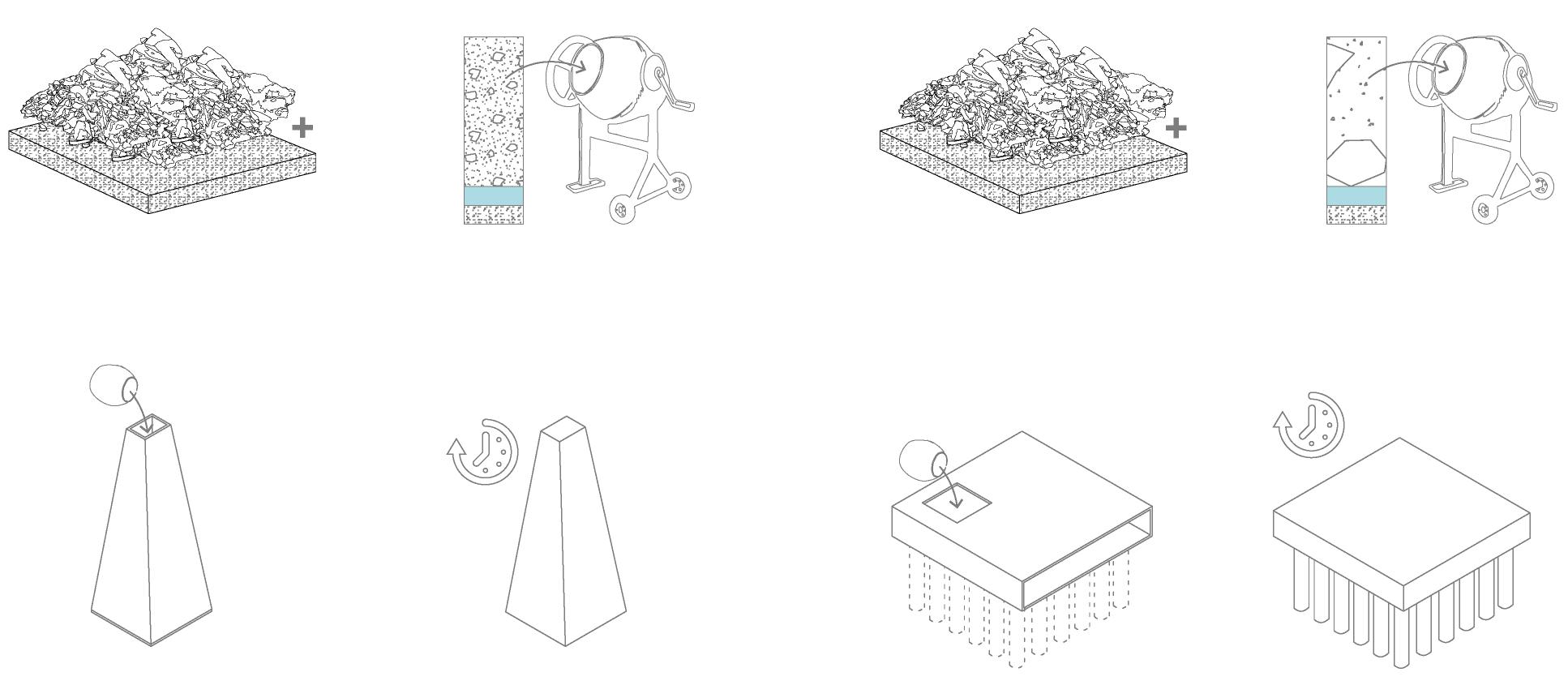
PLINTH & FOUNDATION FABRICATION
Concrete Slab/Pile Structure Fabrication Process
Concrete Aggregate Plinth Structure Fabrication Process
CONCRETE & STONE AGGREGATE PROPERTIES
Repeatable Elements
- Moulds lead to repeatable components within the design. Plinth moulds can be used 10 times due to symmetrical layout.
- Simplicity of plinth forms can reduce curing time and ensure product quality.
Re-Cycling Opportunity
To reduce additional harmful quarrying, stone and sand will be extracted from existing quarries to make up 70% of the final product. Local extraction of water, stone and sand will minimise the construction carbon footprint.
Fire Resistance Properties


Concrete’s ability to resist fire provides a secured means of escape from tower levels. Concrete staircores are placed to provide protection.
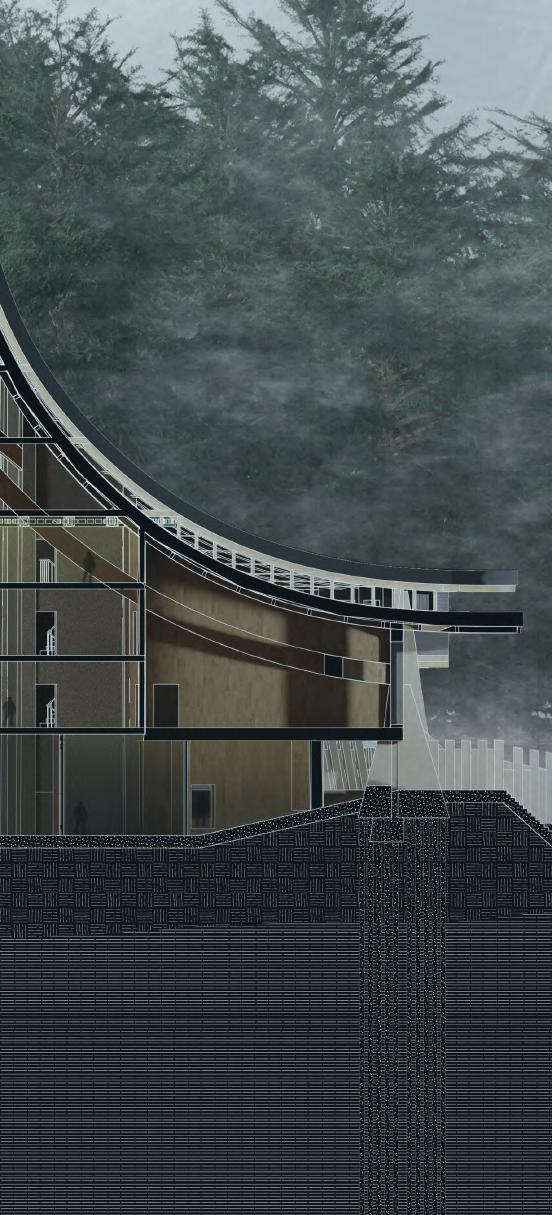
Concrete - Environmental Impact
Social Impact - Material Lifetime
With a maximum lifetime of 100 years, concrete will not have to be replaced during the building’s occupation, minimising additional carbon after handover.
Social Impact - Durability
Placing concrete on lower levels protects upper levels (timber) from degradation. It is ideal for public areas that may experience damage.
Pros - Concrete has a long construction life, and can be re-purposed after the life of the original building.
Pros- Leftover stone from quarries can be re-used.
Cons- Production of concrete contributes to global warming.
Cons - Material cannot be re-used after construction.
57
SECTION 04 BARC0174ADVANCED ARCHITECTURAL DESIGN PORTFOLIO NIKITA NORRIS2022-2024
1. Delivery (stone +sand+cement)
1. Delivery (gravel +sand+cement)
3. Moulding
3. Shuttering
2. Process & mixing
2. Process & mixing
4. Curing
4. Curing


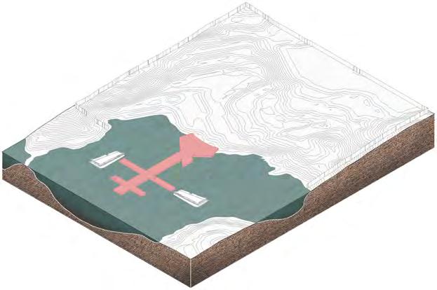

58 Order of Operation Stages 1-6 DETAILED DESIGN CONSTRUCTION SEQUENCE - A NIKITA NORRIS2022-2024
Site Securing (Fencing) - Security fencing installed (protection against wildlife) - Site and soil surveys undertaken - Temporary loading platforms installed 04. Site Excavation/Refill and Foundation - Excavation of top layer peat - Pile Foundation installed - Re-fill of imported soil to act as base - Filling of concrete for foundation and stairs 02. Port Construction - Port pile foundations installed - Port concrete laid (Permanent site access installed) 05. Lower Layer Concrete Laying - Temporary ramps for material transport placed - Concrete Aggregate blocks shipped and installed - Concrete Staircores shuttered and dried
Site Offices/Storage/Accommodation - Site offices,
builder
installed within fencing 06. Primary Structure - CLT shear walls and floors installed floor by floor - Supporting tower CLT beams installed SECTION 04 BARC0174ADVANCED ARCHITECTURAL DESIGN PORTFOLIO
01.
03.
covered storage and
accommodation
-
-
-
- Temporary waterproofing switched for permanent roofing (staggered construction to tower)

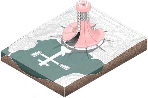
- Construction platform continues tower progression


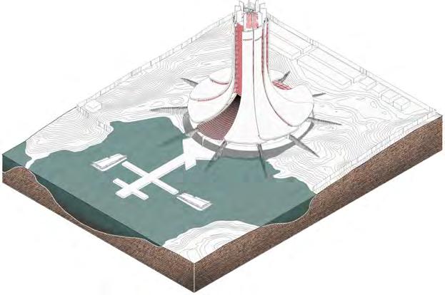
- External walls constructed in covered internal areas
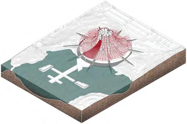
-
-
59
SECTION 04 BARC0174ADVANCED ARCHITECTURAL DESIGN PORTFOLIO
Order of Operation Stages 7-12 DETAILED DESIGN CONSTRUCTION SEQUENCE - B
07. Secondary Structure/Initial Tower
Roof petal glulam beams fixed
Tower construction in progress floor by floor
- Temporary Waterproofing placed to maintain timber moisture content
10. Facade & Glazing
- Staircore/lift core installed
Timber and aluminium façades fitted within building
Glazing installed (removal of all temporary waterproofing)
08. Roofing/Tower Continuation
11. Internal Fit Out
- Internal walls and ceilings installed - Fit out of lighting, services, mechanical ventilation, agriculture, and room loading. - Installation of lantern
09. Tower Finish - Continuation of roof build-up - Tower Structure and capping completed - Removal of construction platform
12. Site Cleared & Handover
NIKITA NORRIS2022-2024
Site cleared from temporary building services - Gas pipe, water turbines connected to building - Hand-over procedure undertaken
DETAILED DESIGN

PRIMARY STRUCTURE


Structural Hierarchy
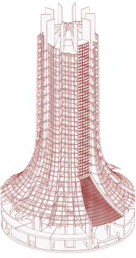
This page describes the necessary strategy for supporting a CLT tower. This includes the application of a wide plinth base. This is necessary for providing a strong support within an area of permafrost.


PRIMARY STRUCTURE - SHEAR WALL SYSTEM


Primary Structure Profile

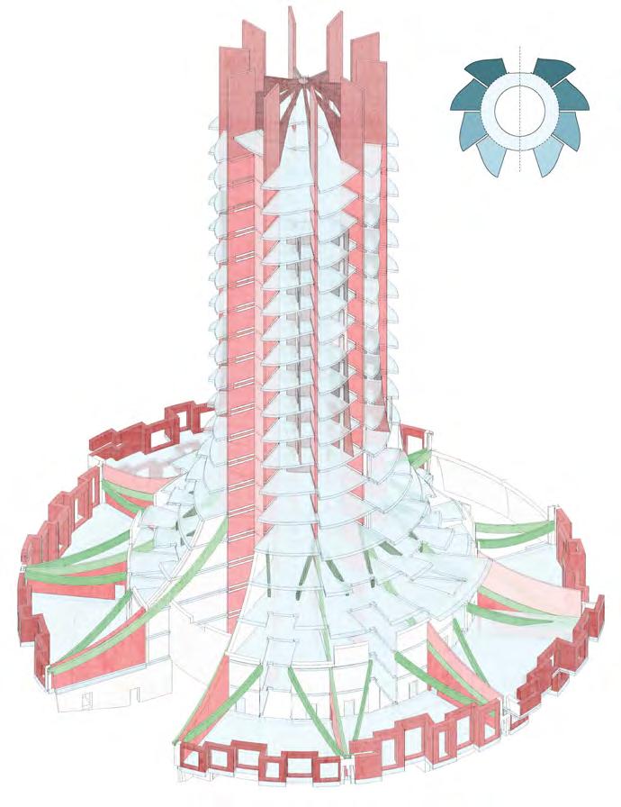
The primary structure of the Tower comprises of CLT Shear Walls, supported by steel trusses/ beams. The load of the tower is then distributed to concrete plinths and foundation.
STRUCTURAL LOAD PATHS
Tower Load Path

Tower-Plinth Load Transfer
Within the Tower, loads are transferred down through CLT/ Steel trusses and cross bracing mitigate uneven forces created by the height of the tower. Due to the height of the tower, heavy loads are distributed to staircores and plinths, that are further distributed along
60
01. Tower (CLT / Steel Connection)
Condition No.1 Condition No.2 35x200mm SHST CLT Timber 35x200mm KD CLT Timber Primary Load Bearing Structure Primary Load Bearing Structure Slotted/Riveted Steel Support Welded Floor Truss Ring CLT Slotted Floor Plate Solid CLT Shear Wall Solid CLT Shear Wall Slotted Concrete/ Aggregate Plinth Concrete Foundation Concrete Pile Foundation PUR1 CLT Glue NIKITA NORRIS2022-2024 SECTION 04 BARC0174ADVANCED ARCHITECTURAL DESIGN PORTFOLIO
02. Plinth (CLT / Concrete Aggregate Connection)
DETAILED DESIGN SECONDARY STRUCTURE
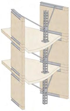
Supporting Components
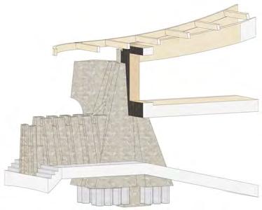
Due to increased loads from proposing a tower typology, steel has been incorporated within the CLT shear walls to mitigate shear, buckling and torsion forces. Glulam has been chosen as a secondary component to support the tower envelope.

61
01. Plinth (Glulam/Concrete Connection)
02. Tower (Steel Cross Bracing Connection)
Condition No.2
Secondary Glulam Load Bearing Structure
Steel Truss Structure (Cross-Braced to
Wall) Steel-Steel Welded Connection Glulam Secondary Structure Supporting Roof Build-up Primary Concrete Plinth Load Bearing Structure Primary Concrete Plinth Load Bearing Structure Steel-CLT Riveted Floor Connection NIKITA NORRIS2022-2024 SECTION 04 BARC0174ADVANCED ARCHITECTURAL DESIGN PORTFOLIO
Condition No.1
Secondary
Shear
DETAILED DESIGN BUILDING LOADS


External/Internal Loads
In addition to the dead and live loads a building will need support during its lifetime, a tower will come under increased strain from external elements such as wind and snow. Special consideration will be needed in regards to hydrostatic and soil loads due to the nature of building on permafrost.
Tower Typology Loads
01. - Dead Loads (Building’s Weight)
02. - Live Loads (Weight of People/Machinery)

03. - Wind Loads (Horizontal Load on Tower)
04. - Snow Loads (Vertical Load on Tower)
05. - Hydrostatic and Soil Loads (Pressure Enacted by Building Load on Ground)
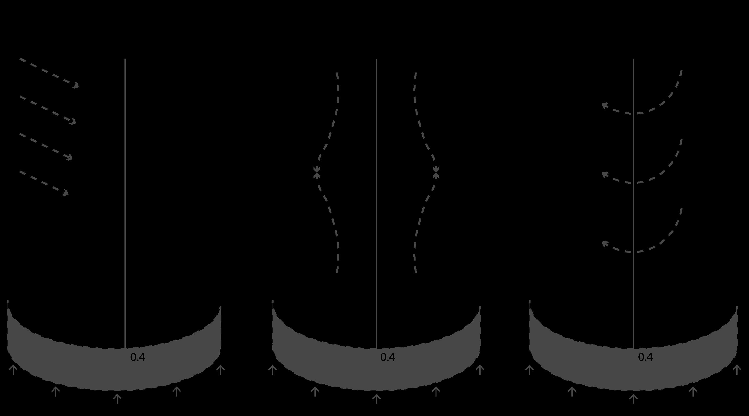
TOWER STRUCTURECOMPRESSION/TENSION FORCES



TOWER STRUCTUREBUCKLING FORCES
TOWER STRUCTURETORSION FORCES
MATERIAL CHOICE - FORCE MITIGATION
62
NIKITA NORRIS2022-2024 SECTION 04 CLT Performs well in both compressive & tensile strength. CLT Consistent performance under compression until breaking point. CLT Minor deformation under torsion, panels are able to recover original shape. Concrete Achieves great compressive strength but poor tensile strength. STEEL Buckling curve diminishes when using thicker steel. STEEL Steel performs well, with breaking point at 2.5 twists.
Compression/Tension Buckling Torsion BARC0174ADVANCED ARCHITECTURAL DESIGN PORTFOLIO
DETAILED DESIGN

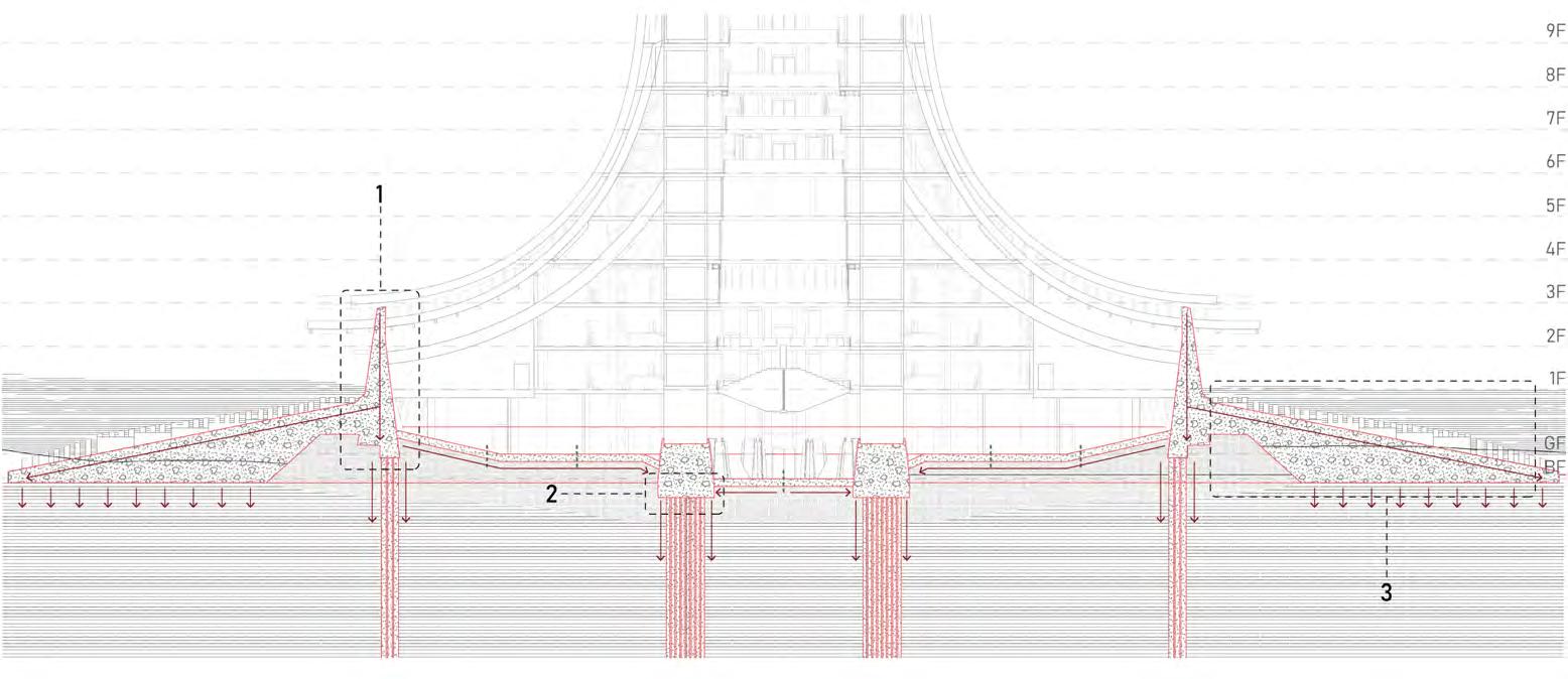
STONE PLINTH LEVEL
Material Choice - Concrete/Stone
This page defines the strategy of concrete/stone aggregate for the foundations and plinths. Simplified forms reduce fabrication and construction time.
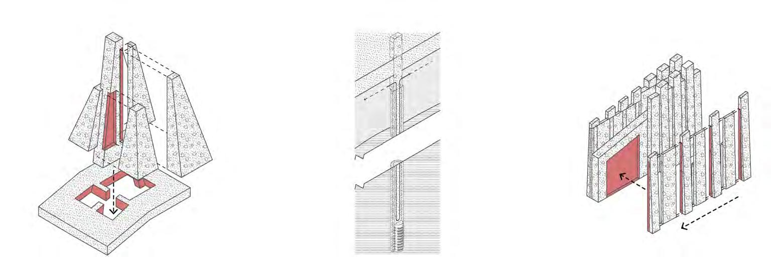
RAFT & PILE SLAB FOUNDATION CONSTRUCTION
Uniform
Foundation
To combat heavy loads from the tower, the foundation is laid as one form to allow for uniform load transfer.
1. CONCRETE AGGREGATE BLOCK ARRANGEMENT
2. CONCRETE PILE TO FOUNDATION CONNECTION
3. CONCRETE AGGREGATE PLINTH LINE ARRANGEMENT
Block
Raft
Block
36° 63
Slab
Plinth Pile Cap Concrete Pile Pressure Treated Timber Pile Foundation Slot Fitting Grease Layer
Slab Pile Cooling Pipe Sand Slurry
(Frost Jacking Resistance)
Notches
Slot Fittings (Minimal Connections)
Slot
Fittings (Minimal Connections)
Transfer Load Direction Slab Movement Joints NIKITA NORRIS2022-2024 SECTION 04 BARC0174ADVANCED ARCHITECTURAL DESIGN PORTFOLIO
Block Slot Fittings
DETAILED DESIGN ENVIRONMENTAL CONSIDERATIONS


Human Comfort - Room Designation
This page allocates the internal environmental conditions required for optimal human comfort.
64
NIKITA NORRIS2022-2024 SECTION 04 BARC0174ADVANCED ARCHITECTURAL DESIGN PORTFOLIO
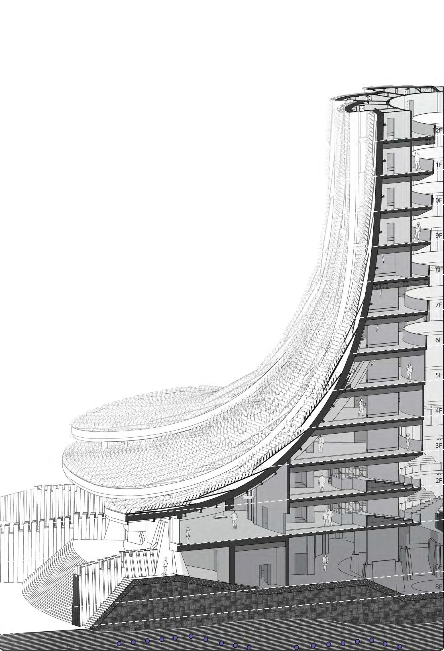
DETAILED DESIGN ENVIRONMENT SECTIONAL STUDY
Considerations
Sectional isometric depicting overview of environmental considerations to building design.
Minimal glazing in tower reduces amount of heat that can escape
Passivhaus standard wall build-up ensures efficient cooling of building in summer and heating in winter (monolithic form improves form factor)
Mega shingles creates additional insulation from snow build-up (shovels) in winter & heat retention from wind flow
Atrium provides light source, minimising need for glazing on external envelope
Circular profile of building provides more uniform intake of air for ventilation as well as reduced strain on building from wind loads
Pine tar coated shingles creates waterproof barrier
Combination of mechanical ventilation / stack ventilation achieves internal positive pressure (negates hot air in summer and cold air in winter from entering building)
Cooling pipes ensure permafrost temperature throughout hotter months
Soil layer creates buffer between foundation and permafrost, mitigating conduction of heat between the two
Raised thermal line mitigates warming of permafrost and open space allows flow of cool wind
Insulated Overhang prevents formation of icicles
Underfloor heating provides low energy intensive solution in isolated environment
Overhang prevents radiation from penetrating ground floor and building during hotter months and allows radiation to penetrate during colder months
Raised ground level provides protection from flooding
65
NIKITA NORRIS2022-2024 SECTION 04 BARC0174ADVANCED ARCHITECTURAL DESIGN PORTFOLIO
Louvre reflectors provide improved atrium lighting and acoustic separation between tower sections
DETAILED DESIGN
Ground Treatment Strategy
This page proposes the strategy of constructing a tower on permafrost through the application of cooling pipes and building form.
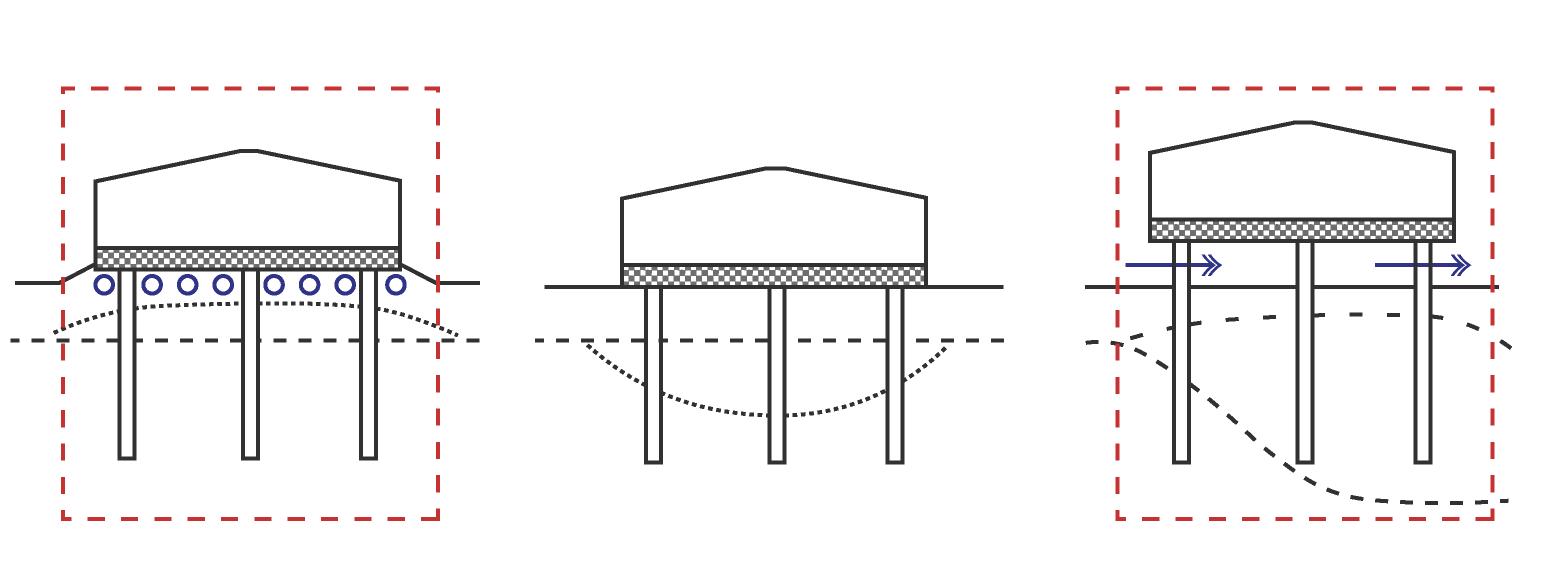
CHOSEN PERMAFROST STRATEGY
Soil aggregate mitigates heat transfer from building to permafrost Insulated floor build up elevated from ground floor
Partially exposed ground floor allows for wind flow
PERMAFROST STRATEGY OPTIONS
Cooling pipes maintain permafrost temperature
1. Elevated Platform (Open Ground Floor)
Pros
- Improved wildlife security
- Building fabric does not warm permafrost Con
- CLT construction requires base touching ground
2. Elevated Platform (Partially Enclosed Ground Floor)

Pros
- Building fabric does not warm permafrost
- Better controlled internal environment Con
- CLT construction requires base touching ground
3. Elevated Platform (Enclosed Ground Floor)
Pro
- Controlled internal environment
Cons
- CLT construction requires base touching ground
- Ground floor may warm permafrost due to enclosed space
4. Elevated Ground (Cooling Pipes)
Pros
- Foundation can sit on ground level
- Cooling pipes moderate permafrost temp
Con
- Additional energy consumption

5. Standard Pile Construction Pros
- Foundation can sit on ground level Cons
- Ground floor will warm permafrost
- Building may collapse due to insufficient cooling
6. Elevated Platform (Preliminary Freezing)

Pros
- Building fabric does not warm permafrost
- Artificial freezing will maintain permafrost temperature
Con
- Expensive procedure
66
PERMAFROST NIKITA NORRIS2022-2024 SECTION 04 BARC0174ADVANCED ARCHITECTURAL DESIGN PORTFOLIO
frozen
construction 8m
base spreads building load
Permafrost artificially
during
Large
DETAILED DESIGN
PERMAFROST - COOLING STRATEGY
Ground Treatment Strategy
This page proposes the strategy of constructing a tower on permafrost through the application of cooling pipes and building form.

COOLING PIPE ANALYSIS
Pile Cooling Pipes
Cooling pipes in pile foundations are necessary to maintain the optimum temperature of permafrost during/after construction.
Internalised Refrigeration System
Refrigerated brine will be used to maintain permafrost temperatures through cooling pipes. Using a mixture of sodium chloride and water, the brine can reach a freezing point of -21.3C.
Estimate Ground Temperature
The graph shows that after 8 metres, the temperature averages at -3.5C. Therefore cooling pipes will be positioned above 8 metres to maintain -3.5C during summer.
Refrigerated Brine (Ingredients)
Sodium Chloride
(Cost Effective)
Water
(Locally Sourced)
67
NIKITA NORRIS2022-2024 SECTION 04 BARC0174ADVANCED ARCHITECTURAL DESIGN PORTFOLIO
Passive Systemics
Analysis of design strategies that influence the thermal properties of the building (internally and externally).
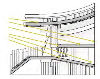
ROOF OVERHANG PERFORMANCE
Solar Gain
Using a 5m overhang, internal spaces receive additional solar gain during spring and autumn where the months are colder. During hotter months, the overhang blocks sunlight from entering. The large overhang is relational to site location in the northern hemisphere, where the summer sun path is lower.


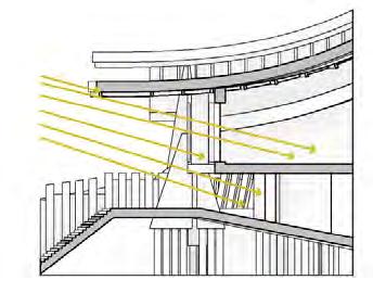
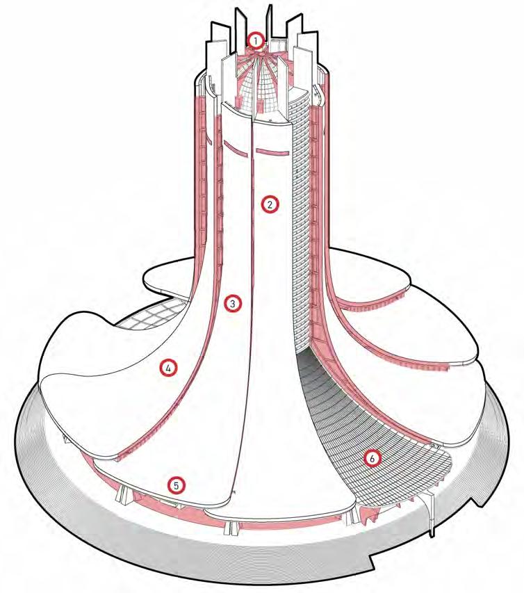
ATRIUM THERMAL PERFORMANCE
Stack Ventilation
A central atrium (1) has been chosen for this design to harness stack ventilation (2). Warm air generated by underfloor heating (3) rises up to the lantern room (4), where it can either escape through vents (5) or provide additional heat for pipes (6). Cool air (7) from mechanical ventilation/ external vent system maintains an optimal environment.

68
NIKITA NORRIS2022-2024 SECTION 04 BARC0174ADVANCED ARCHITECTURAL DESIGN PORTFOLIO
DETAILED DESIGN THERMAL PERFORMANCE
Spring Solstice - March 21st Summer Solstice - June 21st Autumn Solstice - September 21st Winter Solstice - December 21st 9am 9am 9am 9am
Heat Retention
DETAILED DESIGN THERMAL PERFORMANCE - ENVELOPE NIKITA
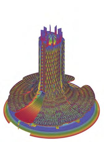

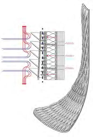

This page analyses the benefits of using mega shingles on the external envelope.
ENVELOPE HEAT RETENTION
1. Weatherproof Membrane Envelope
Heat loss is greater when wind flows against the threshold of a flat envelope.
A textured envelope will disperse wind flow, creating a separation flow region that does not meet the weatherproof membrane. The shingles also act as a barrier against wind.
HEAT LOSS OPTION ANALYSIS
lost (plinth level).
With the application of shingles, the amount of heat lost by the building is minimised.
Site - Wind Flow
Opportunity
The building’s circular profile allows for efficient cool air intake for ventilation. The entrance is situated in the area of least wind direction whereas the petal envelope (vent locations) receive direct wind flow.


69
NORRIS2022-2024 SECTION 04 BARC0174ADVANCED ARCHITECTURAL DESIGN PORTFOLIO
1. Convectional Current
2. Conduction
3. Wind Flow
5. Shingle Wind Barrier 6. Mega Shingle
2. Mega Shingle Envelope
2. Mega Shingle
1. Weatherproof Membrane The heat map diagram (left) shows areas in red where the greatest amount of heat is
DETAILED DESIGN FORM FACTOR
Heat Loss Mitigation - Tower Typology

This page shows the benefits of using a holistic tower typology for greater retention of heat in required areas and better heat dispersion in areas adjacent to permafrost.
INTERNAL FORM FACTOR PERFORMANCE
1. Lantern Room (1:3.7)
Due to the amount of heat generated by the lantern, a large surface area threshold allows for greater heat loss.
2. Monastic Cell (1:0.9)
There is a reduction in heat loss due to only two externally exposed planes (beneficial to internal thermal environment).
3. Office (1:0.6)
There is a reduction in heat loss due to only one externally exposed plane (beneficial to internal thermal environment).
4. Lounge (1:0.12)
Heat loss area is minimal as the lounge partially borders external envelope (beneficial to internal thermal environment).
EXTERNAL FORM FACTOR PERFORMANCE
Form Simplicity
A monolithic form greatly benefits the retention of heat due to a lower form factor. Minimised intrusions/extrusions for structure/windows (shown in red) mitigate an increase of surface area. Components that do extrude (i.e. shear walls) are structural and impact of additional heat loss is minimal. This strategy is essential for building in an extremely cold climate.

5. Overnight Stay (1:3.7)
As a result of elevating the external thermal build-up (permafrost strategy), heat is lost through the floor plate. Underfloor heating will be used to generate heat lost for optimal thermal environment.
6. Entrance (1:1.9)
Situated on the ground, a large heat loss area allows for the regulation of permafrost temperature.
70
NIKITA NORRIS2022-2024 SECTION 04 BARC0174ADVANCED ARCHITECTURAL DESIGN PORTFOLIO
Heat Loss Area - 413m2 Heat Loss Area - 14m2 Heat Loss Area - 701m2 Heat Loss Area - 565m2 Heat Loss Area - 22m2 Heat Loss Area - 22m2 Floor Area - 113m2 Floor Area - 110m2 Floor Area - 189m2 Floor Area - 302m2 Floor Area - 24m2 Floor Area - 36m2
DETAILED DESIGN SOLAR STRATEGY
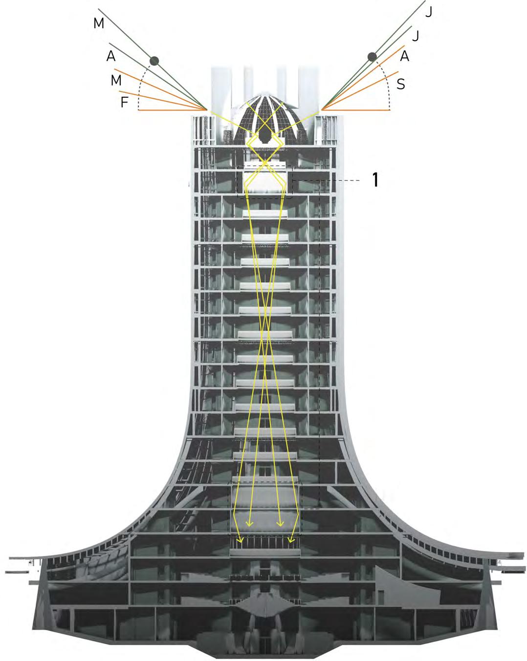
Atrium Daylight Strategy
This page analyses the control of daylight throughout the year to achieve an optimal internal environment for occupants.

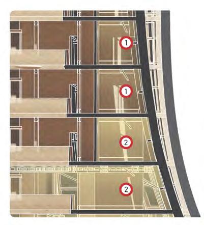
ARTIFICIAL LIGHTING STRATEGY
Fin Reflectors
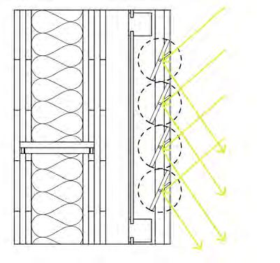
Due to a low angle sun path during the year, sunlight will be reflected by use of the lantern and reflective fins situated in two areas of the tower (1). This will allow light to travel further down the atrium. Depending on the angle of the sun, the fins can rotate. Mylar has been chosen due to its 98% reflectivity and lightness.
Aluminium Frame (50x50mm)
Mylar Laminated Chipboard
Mylar-Vantablack Laminated
Aluminium Fin (Light regulation/ Rotatable)
Motor Powered Pole
Light Fixture Designation
Artificial lighting will be used to achieve the correct lux levels depending on the space’s function (see 01.12 environmental considerations).
71
NIKITA NORRIS2022-2024 SECTION 04 BARC0174ADVANCED ARCHITECTURAL DESIGN PORTFOLIO
DETAILED DESIGN
SOLAR PERFORMANCE - GENERAL
Internal Thresholds
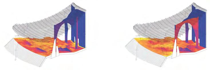
This page analyses the control of daylight throughout the year to achieve an optimal internal environment for occupants.
BUILDING THRESHOLD SOLAR RESPONSE
Solar Strategy - Seasonal Extremes
Summer Day - Overhang prevents high angle sunlight exposure, necessary for prevention of permafrost melting.
Summer Night - Overhang prevents summer night light from penetrating into building.
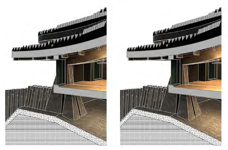
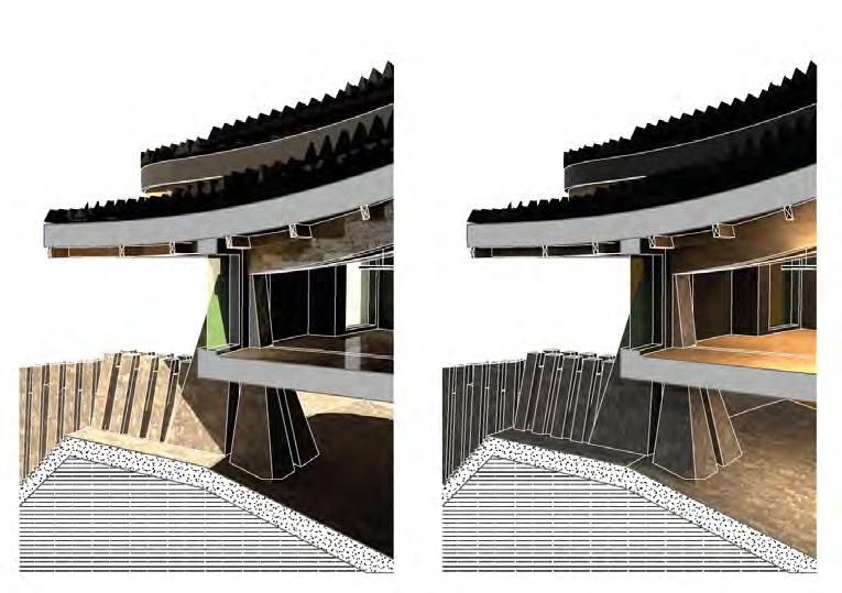
Winter Day - Covered external space regulates permafrost ground temperature.
Winter Night - Covered external space regulates permafrost ground temperature.
Summer - Day
Summer - Night
BUILDING THRESHOLD SOLAR PERFORMANCE (DAYLIGHT ANALYSIS)

MONASTIC CELL (TOWER)
Spring Solstice - March 21st
4. Winter Hours
Summer Solstice - June 21st
Winter Solstice - December 21st
Autumn Solstice - September 21st
REFECTORY (PLINTH)
Spring Solstice - March 21st
Summer Solstice - June 21st
Large roof overhang blocks high level sun and prevents thermal mass heating of permafrost.
Winter - Day
Covered external area provides shading during hot summers.
Raised internal space reduces external environment variance (Heating).
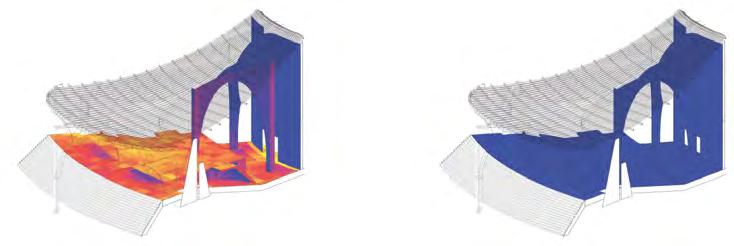
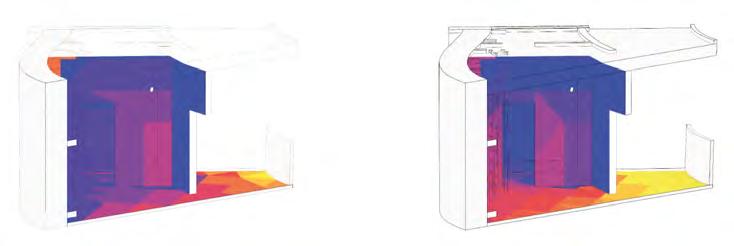
Winter - Night
Autumn Solstice - September 21st
Winter Solstice - December 21st
Insulated overhang prevents heat loss from facade (prevents formation of icicles).
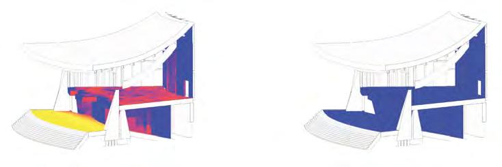

Covered external area prevents warming of permafrost.
Raised internal space reduces external environment variance (Cooling).

ENTRANCE (PLINTH)
Spring Solstice - March 21st
Summer Solstice - June 21st
Additional insulation from snow.
Autumn Solstice - September 21st
Winter Solstice - December 21st
72
NIKITA NORRIS2022-2024 SECTION 04 BARC0174ADVANCED ARCHITECTURAL DESIGN PORTFOLIO
1. Spring Hours 2. Summer Hours 3. Autumn Hours
DETAILED DESIGN SOLAR PERFORMANCE - ATRIUM
Atrium Artificial Lighting Performance
Due to minimal illuminance in winter, an artificial lighting strategy is an integral part of the lighting strategy. Based off a lighthouse lantern, it simulates daylight inside the atrium.
CHOICE OF LIGHT SOURCE - LANTERN
Lantern Lux Analysis
Analysing only light produced by the lantern and external environment, lux levels drop relational to the amount of distance it travels down the atrium. Spatial arrangement has been organised through lux requirements. The lantern achieves 150+ lux in areas where required (i.e. monastic cells). The assembly hall and church are situated at the bottom where less light is required whereas offices are higher up.

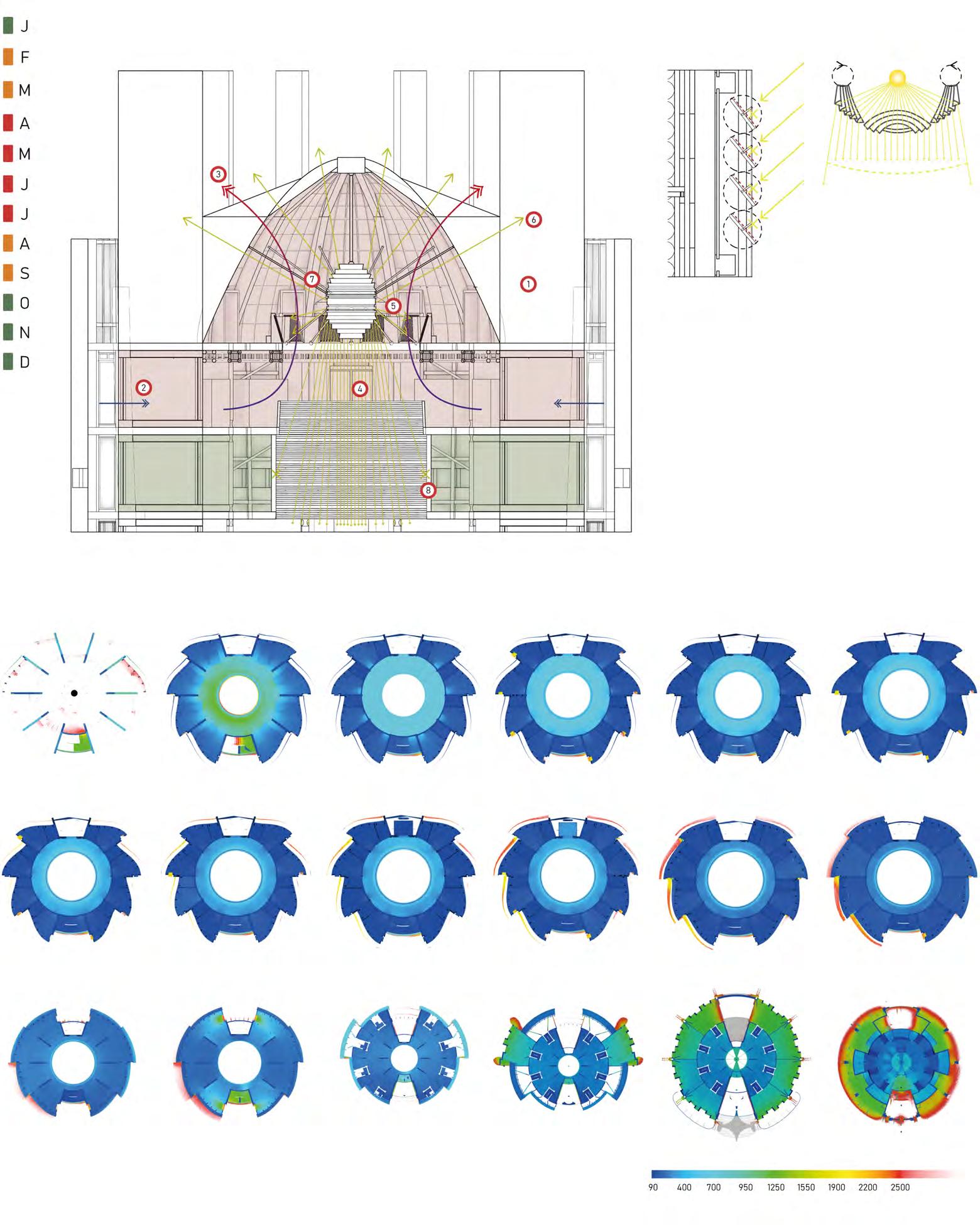
Due to low levels of annual sunlight, a lantern has been chosen as a light source (functioning both internally and externally). The application of Fresnel lens reduces energy required to operate (up to 40%).
Fresnel lens rotated for equal light distribution
The lantern is situated at the top of the tower (1) due to amount of heat generated (up to 100oC). To regulate temperature and keep plant equipment safe, cool air will circulate from the plant room (2) and escape through roof vents (3). The lantern provides many functions such as an internal light source (4), a passive heating system (5), an indication of location for people travelling during dark months (6), and a counterweight (7). A buffer zone has been installed to regulate light paths and temperature (8), ensuring an optimal internal environment further down. Maintenance of plant and lantern will only be carried out when the lantern is off.
73
NIKITA NORRIS2022-2024 SECTION 04 BARC0174ADVANCED ARCHITECTURAL DESIGN PORTFOLIO
PERFORMANCE 20F - Lantern Room 13F - Monastic Cell 7F - Office 19F - Plant 12F - Monastic Cell 6F - Office 17F - Monastic Cell 11F - Monastic Cell 3F - Lounge 16F - Monastic Cell 10F - Monastic Cell 2F -
15F - Monastic Cell 9F - Monastic Cell 1F -
14F - Monastic Cell 8F - Meeting Rooms GF
ATRIUM LANTERN
Assembly Hall
Assembly Hall
- Public Plaza/Church
Lantern Room
Mylar-Vantablack Laminated Aluminium Fin (Light regulation/Rotatable)
DETAILED DESIGN INTERNAL VENTILATION
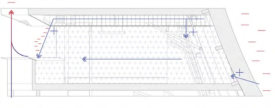

Mechanical Ventilation Strategy
A positive air pressure strategy is appropriate for an atrium that generates stack ventilation. This will have the benefit of keeping out warm air in summer and cool air in winter.
ATRIUM - POSITIVE AIR PRESSURE
With a positive air pressure strategy, internal air has a higher density to external air. Due to an imbalance, thermal buoyancy drives air up the atrium where it escapes through vents. Air is replaced through mechanical ventilation.
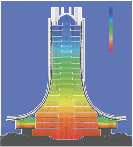
SECTIONAL STUDY - VENTILATION STRATEGY
Vent positioned to hit balustrade, creating pressure separation (aiding travel of air from spaces towards atrium)

To deliver air around a large area, funnels within vents will increase flow speed as a result of higher pressure.
1. ENVELOPE VENTILATION (MECHANICAL)
Gap for air intake (shielded against rain/snow)
Slanted vent (moisture protection)
Mechanical fan
Motorised louvres (Air supply/direction regulation)
2. CEILING VOID VENTILATION
Air vent
Air supply vent
Motorised Louvres (Air supply/direction regulation)
Suspended Plasterboard
Ceiling
3. ATRIUM THRESHOLD VENTILATION
Air vent
Air supply vent
Motorised Louvres (Air supply/direction regulation)

Suspended Plasterboard
Ceiling
Only supply mechanical ventilation required (cost saving/faster installation)
= 4 per hour)
74
NIKITA NORRIS2022-2024 SECTION 04 BARC0174ADVANCED ARCHITECTURAL DESIGN PORTFOLIO
Air flow change rate dependent on room’s function
(Office
Low Air Pressure High Air Pressure Low Air Pressure High Air Pressure Funnel
DETAILED DESIGN
ATRIUM FIRE STRATEGY
Evacuation & Smoke Mitigation
Due to the concerns of the atrium being one compartment, special considerations are taken in the evacuation of occupants during a fire.
SMOKE EXTRACTION STRATEGY
Smoke vents/HVAC’s control extraction of smoke
Lift unavailable in event of fire
Dedicated staircore compartment for fire evacuation
TOWER FIRE SCENARIOS
Dedicated smoke extraction system in staircore
Scenario 1 - Top Atrium
- Ventilation not required
- Sprinklers activated
- Smoke extracted by vents
Scenario 2 - Middle Atrium
- Partial ventilation activated
- Sprinklers activated
- Smoke extracted by vents
Scenario 3 - Bottom Atrium
- Full ventilation activated
- Sprinklers activated
- Smoke extracted by vents
- Fire barriers lowered
Supply vents guide smoke towards atrium/keep smoke within atrium
- Safest means of tower evacuation
SMOKE MITIGATIONS
Sprinklers situated on every floor to mitigate fire spread.
- Moderate risk of tower evacuation
Mechanical extract removes smoke
Supply vents guide smoke towards atrium/keep smoke within atrium
Slanted balustrade creates smoke barrier
Mechanical supply circulates fresh air
- High risk of tower evacuation
Fire barriers prevent spread of smoke outside of atrium
Vents provide controlled supply of air (accelerates extraction of smoke
Emergency Ventilation
In the event of a fire, the ventilation system will operate at full capacity to control the spread and direction of smoke. Several strategies are required for the safe evacuation of an atrium (top,right).
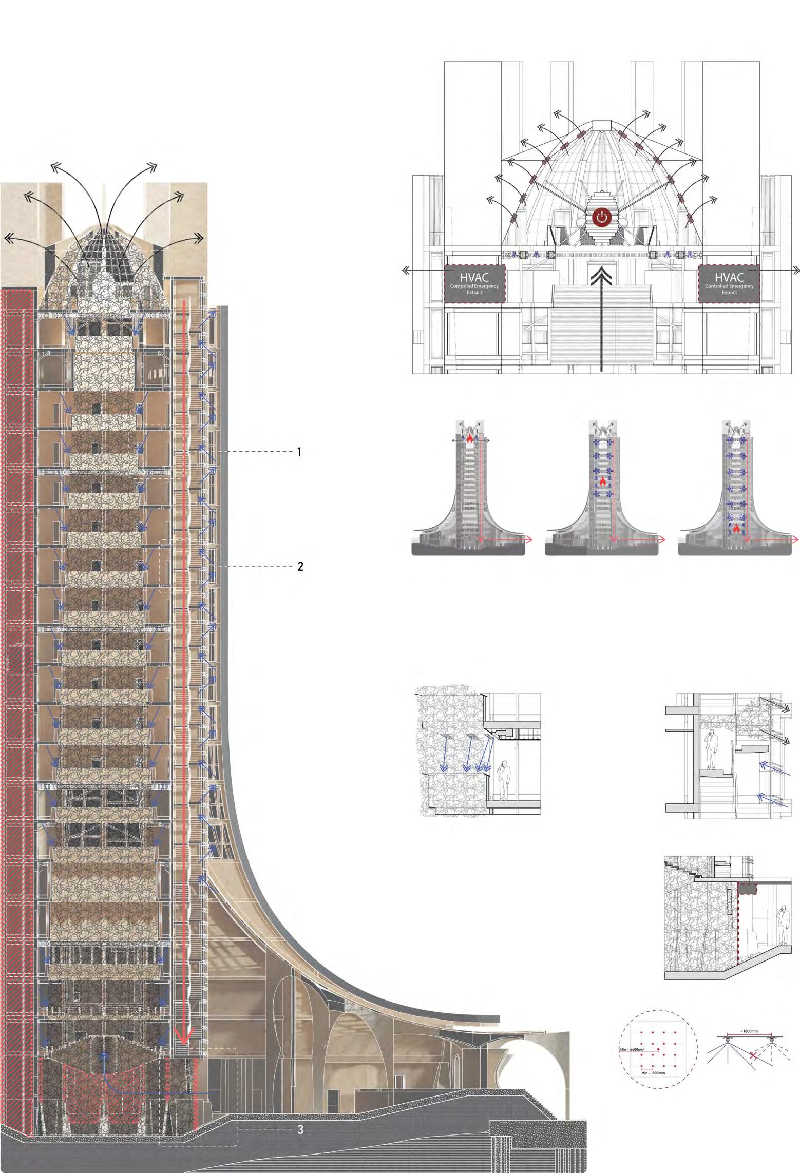
Vents provide controlled supply of air (accelerates extraction of smoke
Fire barriers prevent spread of smoke outside of atrium
Sprinkler System Performance Sprinklers are situated at a minimum of 1800mm to prevent cold soldering.
75
NIKITA NORRIS2022-2024 SECTION 04 BARC0174ADVANCED ARCHITECTURAL DESIGN PORTFOLIO
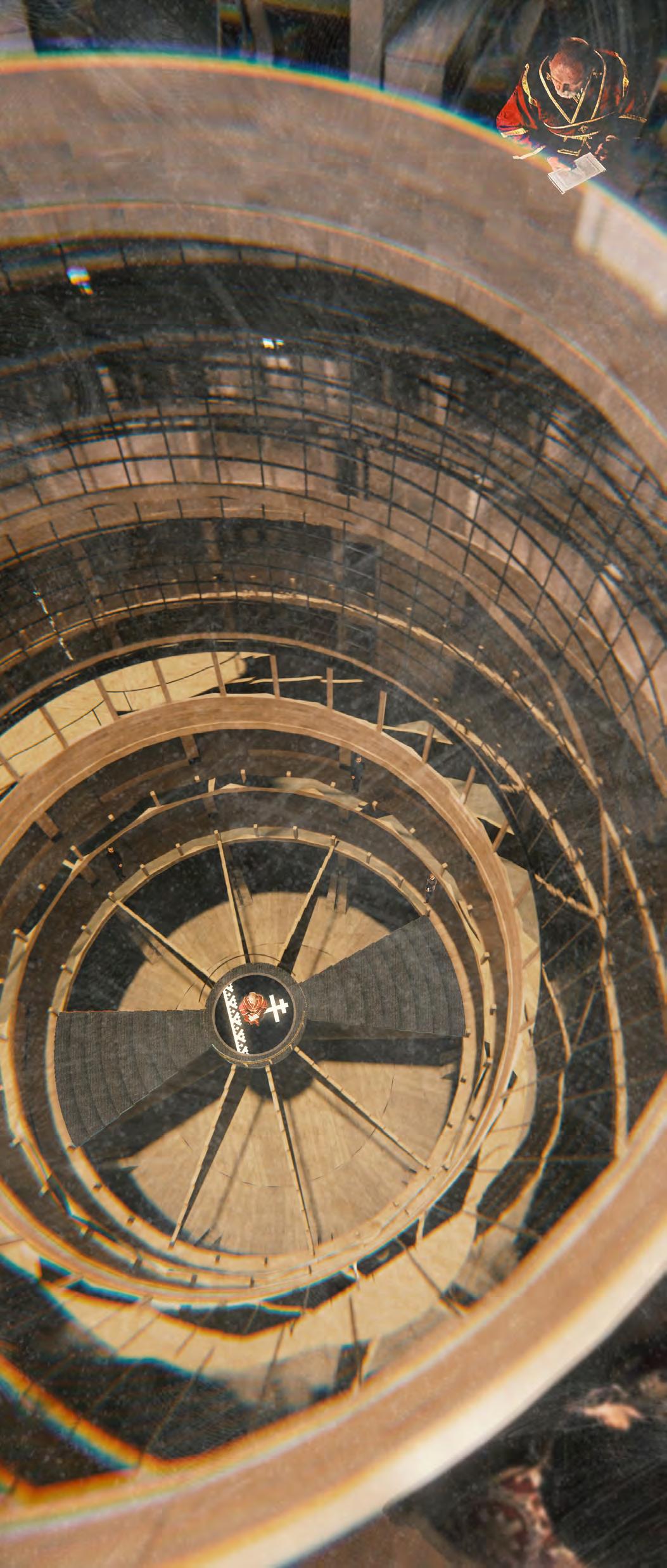
05
FINAL DRAWINGS
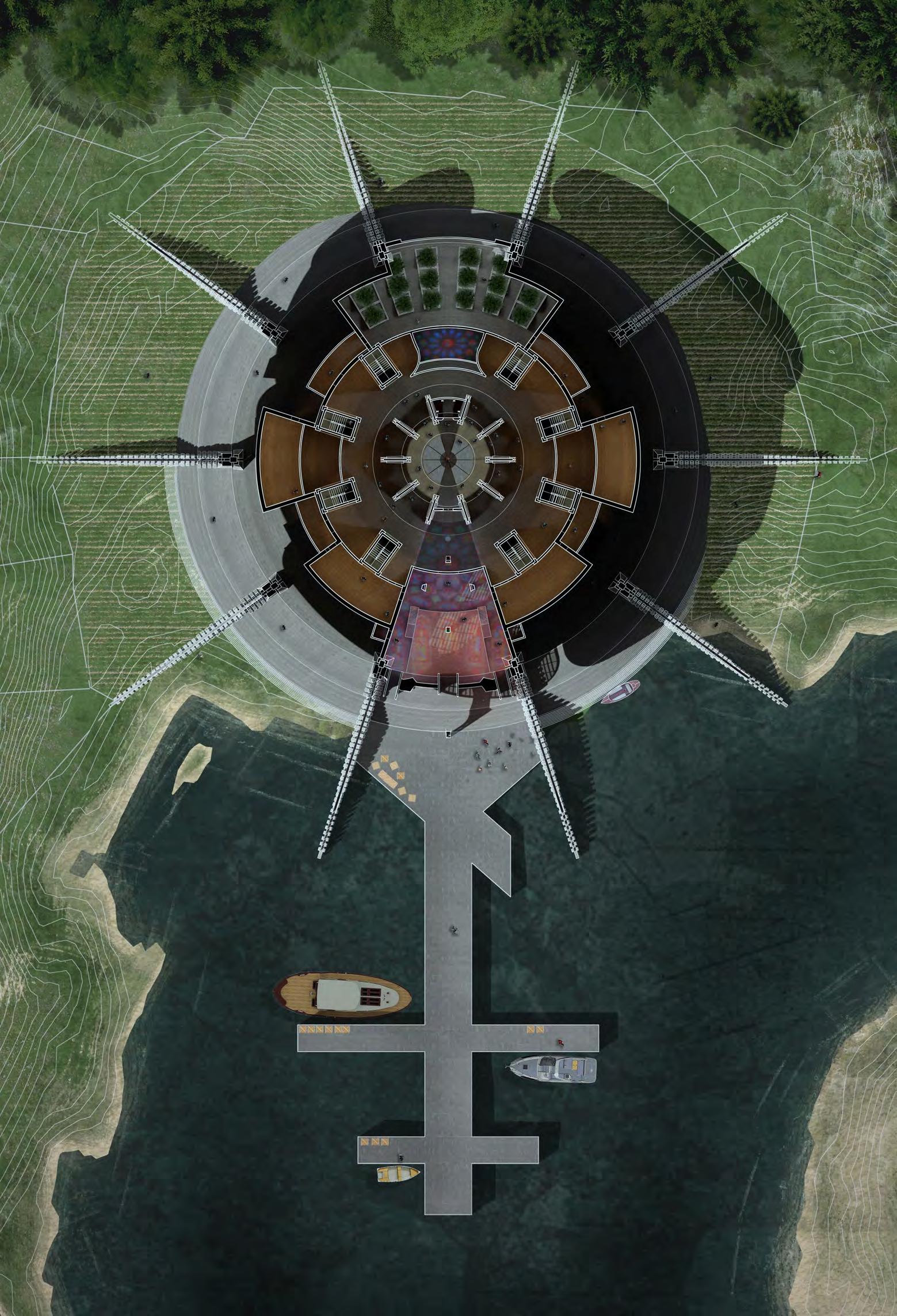
77 FINAL DRAWINGS GROUND FLOOR PLAN 1:500 NIKITA NORRIS2022-2024 SECTION 05 BARC0174ADVANCED ARCHITECTURAL DESIGN PORTFOLIO

1:500 78 FINAL DRAWINGS FIRST FLOOR PLAN NIKITA NORRIS2022-2024 SECTION 05 BARC0174ADVANCED ARCHITECTURAL DESIGN PORTFOLIO
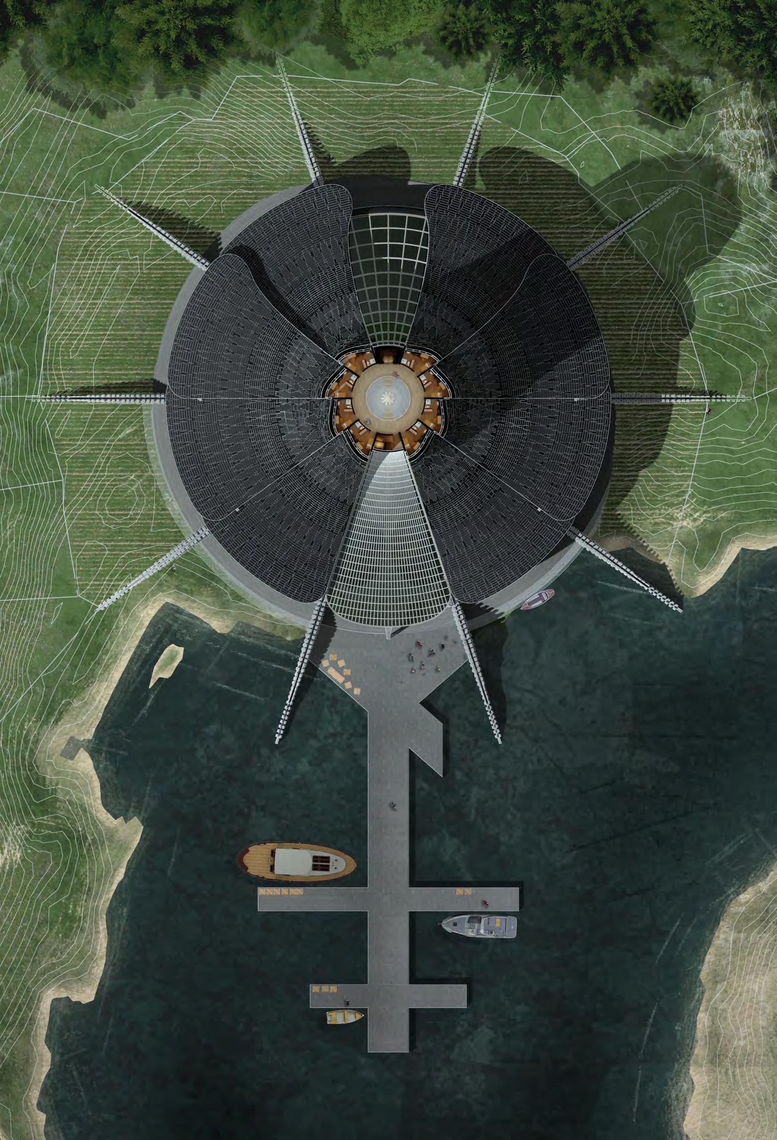
1:500 79 FINAL DRAWINGS FIFTEENTH FLOOR PLAN NIKITA NORRIS2022-2024 SECTION 05 BARC0174ADVANCED ARCHITECTURAL DESIGN PORTFOLIO

1:500 80 FINAL DRAWINGS ROOF PLAN NIKITA NORRIS2022-2024 SECTION 05 BARC0174ADVANCED ARCHITECTURAL DESIGN PORTFOLIO

1:300 81 FINAL DRAWINGS SECTION A NIKITA NORRIS2022-2024 SECTION 05 BARC0174ADVANCED ARCHITECTURAL DESIGN PORTFOLIO

1:300 82 FINAL DRAWINGS SECTION B NIKITA NORRIS2022-2024 SECTION 05 BARC0174ADVANCED ARCHITECTURAL DESIGN PORTFOLIO
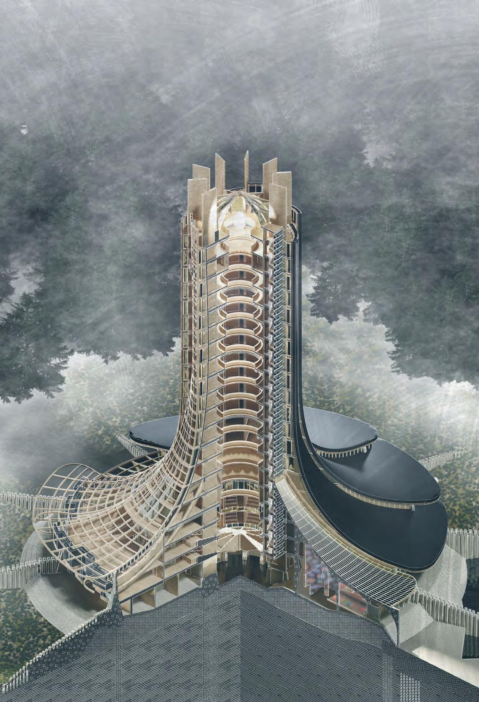
83 FINAL
ISOMETRIC NIKITA NORRIS2022-2024 SECTION 05 BARC0174ADVANCED ARCHITECTURAL DESIGN PORTFOLIO
DRAWINGS
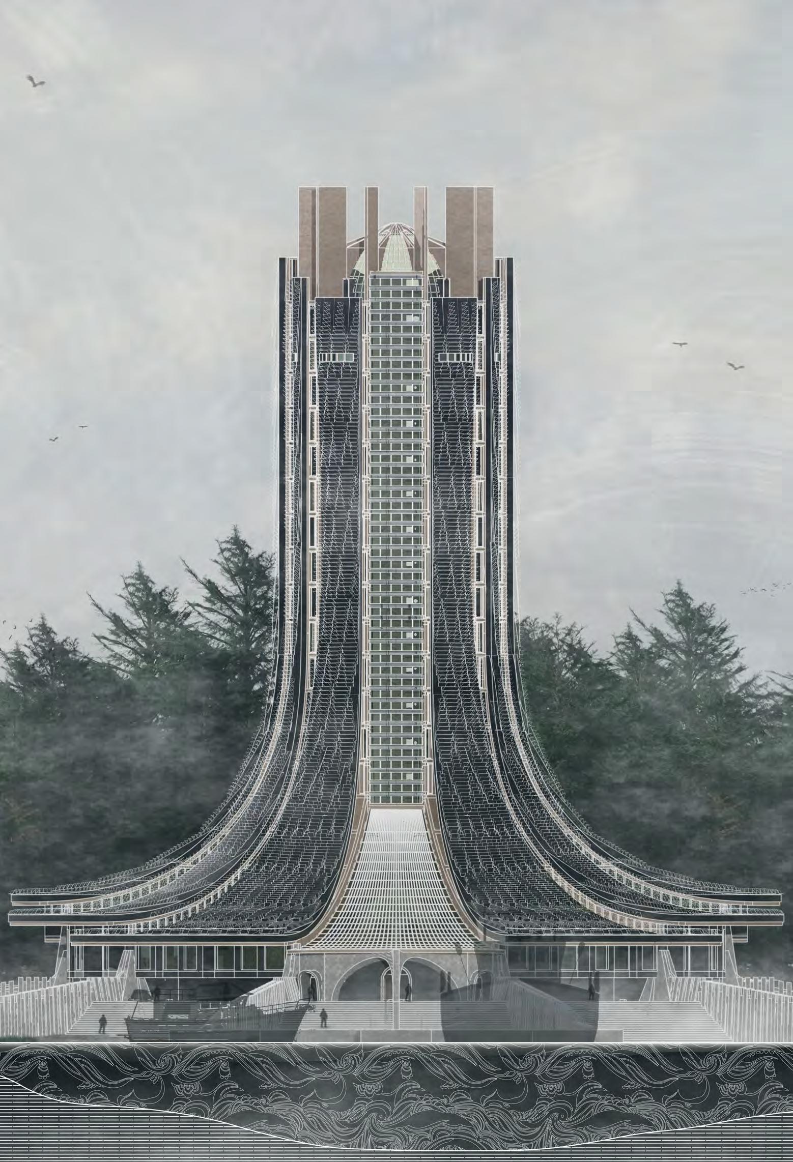
84
FRONT ELEVATION NIKITA NORRIS2022-2024 SECTION 05 BARC0174ADVANCED ARCHITECTURAL DESIGN PORTFOLIO
FINAL DRAWINGS

85
EXTERNAL NIGHT SCENE - ARRIVAL NIKITA NORRIS2022-2024 SECTION 05 BARC0174ADVANCED ARCHITECTURAL DESIGN PORTFOLIO
FINAL DRAWINGS

86 FINAL DRAWINGS EXTERNAL DAY SCENE NIKITA NORRIS2022-2024 SECTION 05 BARC0174ADVANCED ARCHITECTURAL DESIGN PORTFOLIO
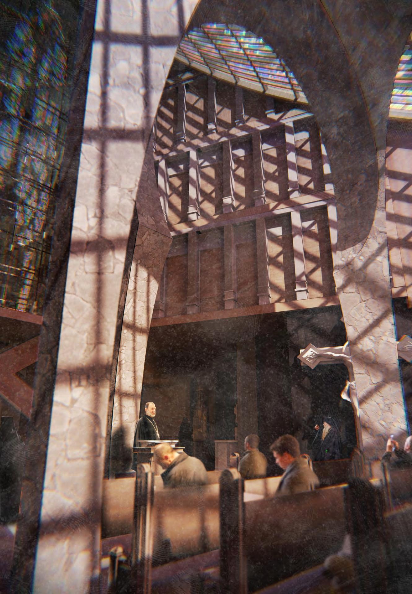
87 FINAL DRAWINGS INTERNAL SCENE - CHURCH NIKITA NORRIS2022-2024 SECTION 05 BARC0174ADVANCED ARCHITECTURAL DESIGN PORTFOLIO
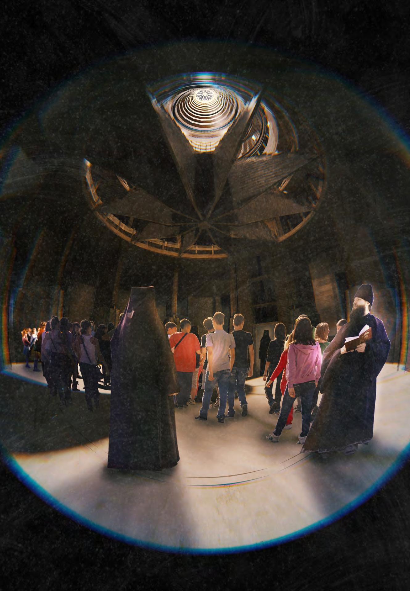
88 FINAL DRAWINGS INTERNAL SCENE - PUBLIC PLAZA NIKITA NORRIS2022-2024 SECTION 05 BARC0174ADVANCED ARCHITECTURAL DESIGN PORTFOLIO
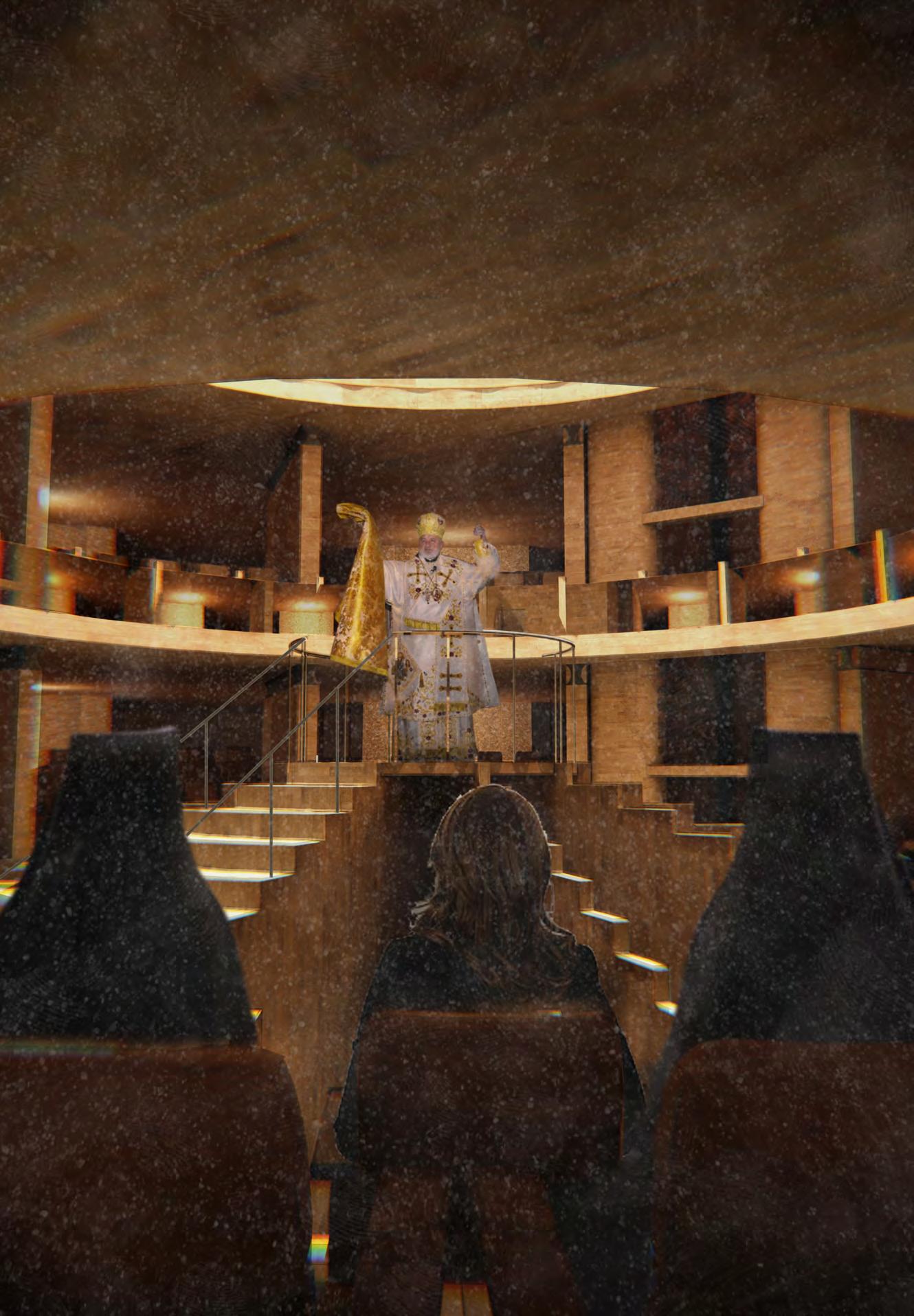
89 FINAL DRAWINGS INTERNAL SCENE - ASSEMBLY HALL NIKITA NORRIS2022-2024 SECTION 05 BARC0174ADVANCED ARCHITECTURAL DESIGN PORTFOLIO

90 FINAL DRAWINGS INTERNAL SCENE - ATRIUM NIKITA NORRIS2022-2024 SECTION 05 BARC0174ADVANCED ARCHITECTURAL DESIGN PORTFOLIO

All work produced by Unit 14
Unit book design by Charlie Harriswww.bartlett.ucl.ac.uk/architecture
Copyright 2021
The Bartlett School of Architecture, UCL All rights reserved.

No part of this publication may be reproduced or transmited in any form or by any means, electronic or mechanical, including photocopy, recording or any information storage and retreival system without permission in writing from the publisher.

-

@unit14_ucl UNIT
CONSTRUCTED FUTURES 2023


At the center of Unit 14’s academic exploration lies Buckminster Fuller’s ideal of the ‘The Comprehensive Designer’, a master-builder that follows Renaissance principles and a holistic approach. Fuller referred to this ideal of the designer as somebody who is capable of comprehending the ‘integrateable significance’ of specialised findings and is able to realise and coordinate the commonwealth potentials of these discoveries while not disappearing into a career of expertise. Like Fuller, we are opportunists in search of new ideas and their benefits via architectural synthesis.
As such Unit 14 is a test bed for exploration and innovation, examining the role of the architect in an environment of continuous change. We are in search of the new, leveraging technologies, workflows and modes of production seen in disciplines outside our own. We test ideas systematically by means of digital as well as physical drawings, models and prototypes. Our work evolves around technological speculation with a research-driven core, generating momentum through astute synthesis. Our propositions are ultimately made through the design of buildings and through the in-depth consideration of structural formation and tectonic. This, coupled with a strong research ethos, will generate new and unprecedented, one day viable and spectacular proposals. They will be beautiful because of their intelligence - extraordinary findings and the artful integration of those into architecture.
The focus of this year’s work evolves around the concept of ‘Constructed Futures’. The term aims to describe architecture and as such fundamentally human future as the result of the architect’s highest degree of synthesis of underlying principles. Constructional logic, spatial innovation, typological organisation, environmental and structural performance are all negotiated in a highly iterative process driven by intense architectural investigation. Inspiration for inherent principles of organisational intelligence can be observed in both biotic and abiotic systems, in all spatial arrangements where it is critical for the overall performance of the developed order. Through the deep understanding of constructional principles, we will generate highly developed architectural systems of unencountered intensity where spatial organisation arises as a result of sets of mutual interactions. Observation as well as re-examination of civilisatory developments will enable us to project near future scenarios and position ourselves as avant-garde in the process of designing a comprehensive vision for the forthcoming. The projects will take shape as research based imaginative tales, architectural visions driven by speculation.
Thanks to: ALA, DaeWha Kang Design, Foster + Partners, Heatherwick Studio, Populous, RSH+P, Seth Stein Architects, ZHA, Expedition Engineering

UNIT 14 @unit14_ucl All work produced by Unit 14 Unit book design by Charlie Harriswww.bartlett.ucl.ac.uk/architecture Copyright 2021 The Bartlett School of Architecture, UCL All rights reserved.No part of this publication may be reproduced or transmitted in any form or by any means, electronic or mechanical, including photocopy, recording or any information storage and retreival system without permission in writing from the publisher.

 Cover design by Charlie Harris


