Italiana La Metallurgia
International Journal of the Italian Association for Metallurgy
n. 10 ottobre 2024
Organo ufficiale dell’Associazione Italiana di Metallurgia. Rivista fondata nel 1909

International Journal of the Italian Association for Metallurgy
n. 10 ottobre 2024
Organo ufficiale dell’Associazione Italiana di Metallurgia. Rivista fondata nel 1909

International Journal of the Italian Association for Metallurgy
Organo ufficiale dell’Associazione Italiana di Metallurgia. HouseorganofAIMItalianAssociationforMetallurgy. Rivista fondata nel 1909
Direttore responsabile/Chiefeditor: Mario Cusolito
Direttore vicario/Deputydirector: Gianangelo Camona
Comitato scientifico/Editorialpanel: Marco Actis Grande, Silvia Barella, Paola Bassani, Christian Bernhard, Massimiliano Bestetti, Wolfgang Bleck, Franco Bonollo, Irene Calliari, Mariano Enrique Castrodeza, Emanuela Cerri, Vlatislav Deev, Andrea Di Schino, Donato Firrao, Bernd Kleimt, Carlo Mapelli, Denis Jean Mithieux, Roberto Montanari, Marco Ormellese, Mariapia Pedeferri, Massimo Pellizzari, Barbara Previtali, Evgeny S. Prusov, Dario Ripamonti, Dieter Senk
Segreteria di redazione/Editorialsecretary: Marta Verderi
Comitato di redazione/Editorialcommittee: Federica Bassani, Gianangelo Camona, Mario Cusolito, Carlo Mapelli, Federico Mazzolari, Marta Verderi, Silvano Panza
Direzione e redazione/Editorialandexecutiveoffice: AIM - Via F. Turati 8 - 20121 Milano tel. 02 76 02 11 32 - fax 02 76 02 05 51 met@aimnet.it - www.aimnet.it
Reg. Trib. Milano n. 499 del 18/9/1948. Sped. in abb. Post. - D.L.353/2003 (conv. L. 27/02/2004 n. 46) art. 1, comma 1, DCB UD
Immagine in copertina: Shutterstock

Gestione editoriale e pubblicità Publisher and marketing office: siderweb spa sb
Via Don Milani, 5 - 25020 Flero (BS) tel. 030 25 400 06 - fax 030 25 400 41 commerciale@siderweb.com - www.siderweb.com
La riproduzione degli articoli e delle illustrazioni è permessa solo citando la fonte e previa autorizzazione della Direzione della rivista. Reproduction in whole or in part of articles and images is permitted only upon receipt of required permission and provided that the source is cited.
siderweb spa sb è iscritta al Roc con il num. 26116

n.10 ottobre 2024
Anno 115 - ISSN 0026-0843
Editoriale / Editorial
Additive Manufacturing: tecnologia del presente per una spinta innovativa futura
Ilaria Rampin - Pometon . pag.05
Memoriescientifiche/Scientificpapers
FabbricazioneAdditiva/AdditiveManufacturing
Influenzadiuntrattamentosuperficialeduplexsullaresistenzaadimpatto eafaticadiunacciaio18Ni300prodottoperL-PBF
T.Tekin,L.Maines,G.Ischia,F.Naclerio,R.Ipek,A.Molinari............................................................................pag.07
StruttureTPMSinInconel718:analisidellafabbricabilitàtramiteL-PBFe caratterizzazionemicrostrutturale
A.Santoni,M.Cabibbo,M.L.Gatto,G.Grima,E.Santecchia,K.Sleem,S.Spigarelli,M.Palladino.......................pag.15
A tribological assessment of 17-4PH stainless steel manufactured by binder jetting
L. Fabiocchi, M. Mariani, A. Lucchini Huspek, M. Pozzi, M. Bestetti, S. Graziosi, N. Lecis ............................................ pag.26
Finitura green di componenti in rame ottenuti tramite tecnologia additive manufacturing
A. Acquesta, M. Smet, B. Van Hooreweder, T. Monetta pag.35
Fonderia e solidificazione / Foundry and solidification - lavoro vincitore del Premio Daccò 2024
Comparison of recycled High Pressure Die Casting AlSi10MnMg alloys for automotive structural components produced in laboratory and industrial environment
A. Bongiovanni, A. Castellero ............................................................................................................................................. pag.42
Atti e notizie / AIM news
Premiazioni 40° Convegno Nazione AIM ........................................................................ pag.53
Eventi AIM / AIM events ...................................................................................................... pag.56
Normativa / Standards ....................................................................................................... pag.58
NOVEMBER
The environmental and economical sustainability of the metallurgical industries depends on the possibility to recover and recycle the metallic materials after the use of the metallic products. The new challenge is a zero-waste metallurgical process including the recovery of the materials composing the products. Such a challenging achievement can be fulfilled by a perspective involving commercial, economic and technical issues. Although recycling is an intrinsic feature of all the metallurgical processes, an efficient circular approach needs to take into account a correct selection and cleaning of the metallic and glassy-ceramic materials in order to allow their use in the process avoiding or limiting the exploitation and the consumption of the natural resources. Such a view imposes a multidisciplinary approach where the application of complex mechanical system, innovative chemical plants, electromagnetic devices, biotechnological techniques and managing algorithm even ruled by artificial intelligence (i.e. for scrap selection, removal of the organic burden, extraction of valuable chemical elements etc.) have to be applied. An efficient action inspired to the circular economy has to take into account a comprehensive vision where the recycling is associated to an efficient material and energy exploitation that implies an overall decrease of the polluting elements and greenhouse gases. Website: https://www.aimnet.it/circmet.htm
ORGANISED BY WITH THE SUPPORT OF
“"Dai componenti meccanici agli impianti biomedicali, l'evoluzione dell'AM nel campo dei metalli sta aprendo nuove frontiere, offrendo possibilità di design e funzionalità che superano le tecniche tradizionali di lavorazione."
“From mechanical components to biomedical implants, the evolution of AMinmetalsisopening upnewfrontiers,offering designandfunctional possibilities that surpass traditionalmachining techniques.”
L'Additive Manufacturing (AM) sta ridefinendo il modo in cui materiali avanzati come acciaio e leghe speciali vengono lavorati per applicazioni ad alte prestazioni. Dai componenti meccanici agli impianti biomedicali, l'evoluzione dell'AM nel campo dei metalli sta aprendo nuove frontiere, offrendo possibilità di design e funzionalità che superano le tecniche tradizionali di lavorazione.
In questo numero dedicato alle tecnologie additive sono stati selezionati alcuni studi, presentati durante il Convegno Nazionale AIM, che spaziano dal settore industriale a quello biomedico.
Nel settore industriale, una delle aree di interesse è rappresentata dalla produzione di componenti in acciaio per componenti meccanici quali utensili e stampi. Tradizionalmente, vengono prodotti attraverso processi sottrattivi come la fresatura e la forgiatura. Tuttavia, l'AM consente di progettare strutture interne complesse e geometrie che riducono il peso, mantenendo la resistenza e la durabilità.

Additive Manufacturing (AM) is redefining the way advanced materials such as steel and special alloys are processed for high-performance applications. From mechanical components to biomedical implants, the evolution of AM in metals is opening up new frontiers, offering design possibilities and functionality that surpass traditional machining techniques.
In this issue dedicated to additive technologies, we have selected a number of studies, presented during the AIM National Conference, ranging from the industrial to the biomedical sector.
In the industrial sector, one area of interest is the production of steel components for mechanical parts such as tools and moulds. Traditionally, they are producedthroughsubtractiveprocessessuchasmilling and forging. However, AM allows the design of complex internal structures and geometries that reduce weight while maintaining strength and durability.
TheuseofsteelinAMallowsthemechanicalperformance
L’uso dell’acciaio in AM permette di ottimizzare le prestazioni meccaniche dei pezzi ed è per questo che è sempre più presente nel settore automobilistico e aerospaziale.
Le possibilità dell'AM non si limitano ai soli materiali convenzionali.
Il Nitinol, una lega a memoria di forma composta da nichel e titanio, sta emergendo come uno dei materiali più promettenti per le applicazioni biomedicali anche processato mediante tecnologie additive. L’AM consente di produrre strutture in Nitinol con una precisione senza precedenti, migliorando l'efficacia e la personalizzazione dei dispositivi medici per rispondere meglio alle esigenze dei pazienti.
L’aspetto chiave che emerge dai numerosi lavori presentatati durante il Convegno Nazionale AIM è l’importanza della collaborazione tra mondo accademico e industria. Le università e i centri di ricerca stanno lavorando a stretto contatto con le imprese per esplorare nuovi materiali e processi di produzione, accelerando l'innovazione. Queste sinergie hanno già portato a sviluppi significativi nel campo dell'additive metallo, con tecniche sia SLM che DED, che stanno trasformando la produzione di componenti metallici complessi. Guardando al futuro, i nuovi trend nell'Additive Manufacturing indicano un’espansione nell’uso di materiali ibridi e multi-materiale, progettazioni ottimizzate grazie all’intelligenza artificiale e soluzioni più efficienti in termini energetici. L’AM si sta rapidamente affermando non solo come una tecnologia di produzione, ma come una spinta innovativa in settori industriali e biomedicali, in cui i limiti tradizionali della manifattura vengono costantemente superati.
of parts to be optimised, which is why it is increasingly being used in the automotive and aerospace industries. The possibilities of AM are not limited to conventional materials.
Nitinol, a shape memory alloy composed of nickel and titanium, is emerging as one of the most promising materials for biomedical applications also processed using additive technologies. AM makes it possible to produce Nitinol structures with unprecedented precision, improving the effectiveness and customisation of medical devices to better meet patients' needs.
The key aspect that emerges from the many papers presented at the AIM National Conference is the importance of collaboration between academia and industry. Universities and research centres are working closely with companies to explore new materials and manufacturingprocesses,acceleratinginnovation.These synergies have already led to significant developments in the field of metal additive manufacturing, with both SLM and DED techniques transforming the production of complex metal components.
Looking to the future, new trends in Additive Manufacturing indicate an expansion in the use of hybrid and multi-material materials, optimised designs through artificial intelligence and more energy-efficient solutions. AM is rapidly establishing itself not only as a manufacturingtechnology,butasaninnovativethrustin industrial and biomedical sectors, where the traditional limits of manufacturing are constantly being exceeded.

T.Tekin,L.Maines,G.Ischia,F.Naclerio,R.Ipek,A.Molinari
In questo lavoro è stata studiata l’influenza di un trattamento superficiale duplex, nitrurazione in plasma seguita da PVD di un rivestimento Ti(C,N), sulle proprietà meccaniche di un acciaio maraging 18Ni300 prodotto con la tecnologia Laser Powder Bed Fusion (L-PBF). Il trattamento superficiale è stato eseguito con due intensità diverse della nitrurazione. Sono state studiate la resistenza ad impatto (Charpy) su provini intagliati e la resistenza a fatica assiale. Come riferimento è stato considerato lo stesso acciaio invecchiato direttamente senza la solubilizzazione.
I risultati hanno evidenziato come il trattamento duplex non influenzi significativamente la resistenza all’impatto e promuova un sensibile aumento della resistenza a fatica. I risultati sono interpretati sulla base della combinazione dell’indurimento superficiale indotto dalla nitrurazione e dell’aumento della percentuale di austenite causato dall’esposizione del materiale alla temperatura del trattamento superficiale.
PAROLE CHIAVE: LASER POWDER BED FUSION, ACCIAIO MARAGING 18NI300, TRATTAMENTO
SUPERFICIALE DUPLEX, RESISTENZA ALL’IMPATTO, RESISTENZA A FATICA
INTRODUZIONE
Gli acciai maraging sono fra i materiali più studiati ed utilizzati nella produzione di component meccanici con la tecnologia Laser Powder Bed Fusion (L-PBF) grazie alla loro eccellente saldabilità che li rende particolarmente adatti a questa tecnologia [1]. La microstruttura martensitica praticamente priva di carbonio rinforzata dalla precipitazione di composti intermetallici consente di ottenere un’eccellente combinazione di resistenza meccanica, duttilità e tenacità alla frattura [2, 3]. Le proprietà ottenibili con la tecnologia L-PBF sono confrontabili con quelle dei pezzi prodotti con le tecnologie convenzionali [4]. Un’applicazione potenzialmente interessante della tecnologia L-PBF dell’acciaio maraging è la produzione di utensili per la pressatura delle polveri metalliche. Si tratta di componenti di elevata complessità geometrica, che sono soggetti ad elevate sollecitazioni statiche e dinamiche e ad usura in esercizio. Tuttavia la durezza massima ottenibile dopo il trattamento termico di indurimento di precipitazione (53-55 HRc) è insufficiente per garantire una buona resistenza all’usura. Questa limitazione può essere superata con i trattamenti di indurimento superficiale, in particolare i trattamenti duplex costituiti da
T. Tekin, L. Maines, G. Ischia, A. Molinari
Università di Trento, Italia
F. Naclerio
Pontillo Officine Meccaniche & C., Scafati (SA), Italia
R. Ipek
Ege University, Izmir, Turchia
un trattamento termochimico seguito da un rivestimento PVD [5-9]. Fra i trattamenti termochimici dell’acciaio, la nitrurazione è la più adatta perché viene eseguita a temperature confrontabili con quella dell’invecchiamento e pertanto la precipitazione dei composti intermetallici avviene durante la nitrurazione stessa. L’influenza positiva della nitrurazione in plasma sulle proprietà di superficie dell’acciaio maraging forgiato è stata studiata in alcuni lavori [10-13]. Relativamente all’acciaio prodotto con L-BBF, Hong e al. Hanno recentemente dimostrato che le migliori proprietà si ottengono effettuando la nitrurazione in plasma direttamente sul materiale as-built [14]. Il trattamento di indurimento superficiale potrebbe causare una diminuzione della resistenza all’impatto dell’acciaio maraging. Allo stesso tempo, è atteso un aumento della resistenza a fatica. La resistenza all’impatto dell’acciaio maraging prodotto con L-PBF è oggetto di alcuni articoli in letteratura che si concentrano sull’effetto del trattamento termico eseguito con e senza lo stadio di solubilizzazione prima dell’invecchiamento [15-21]. La resistenza a fatica è maggiormente studiata. L’acciaio
maraging prodotto con L-PBF ha un limite a fatica pari al 20-30% del carico di rottura, a differenza dell’acciaio forgiato che raggiunge il 40-60% [22]. Poiché questa differenza con gli acciai forgiati è dovuta sostanzialmente ai difetti della microstruttura tipici del processo L-PBF, i lavori in letteratura sono soprattutto focalizzati sullo studio dell’effetto di tali difetti (lack of fusion e porosità da gas intrappolato, inclusioni non metalliche) sulla nucleazione e la propagazione della cricca di fatica [2328].
Non esistendo quindi lavori sull’effetto dei trattamenti di indurimento superficiale su queste due proprietà dell’acciaio maraging prodotto con L-PBF, è stato condotto uno studio effettuando un trattamento superficiale duplex sull’acciaio 18Ni300. In questo articolo vengono presentati i principali risultati ottenuti con le prove di impatto Charpy e le prove di fatica assiale.
MATERIALE E PROCEDURA SPERIMENTALE
La polvere utilizzata ha la composizione chimica nominale riassunta nella Tabella 1.
Tab.1 - Composizione chimica della polvere di acciaio 18Ni-300 (% in peso).
Tutti i campioni sono stati prodotti utilizzando una macchina SLM 280 HL 2.0 con i seguenti parametri: potenza del laser: 100 W; velocità di scansione: 420 mm/s; spessore dello strato: 0,03 mm; distanza tra i vettori: 0,05 mm. La densità è stata verificata con il metodo di Archimede ed è risultata superiore al 99,5% della densità teorica. Sono
stati prodotti campioni per le prove Charpy (55x10x10 mm con intaglio a V) e campioni per le prove di fatica assiale; il disegno di quest’ultimi è riportato in Figura 1. I campioni per le prove di impatto sono stati fabbricati lungo la direzione di stampa Z e la direzione del moto del roller Y; quelli di fatica solo lungo la direzione Z.
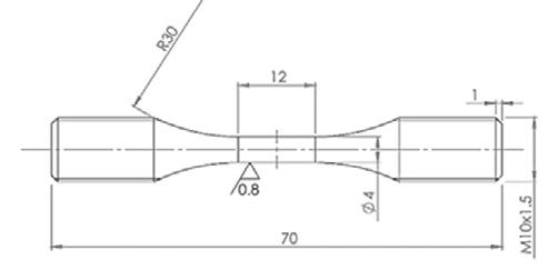
Fig.1 - Campione per le prove di fatica assiale.
Sono stati eseguiti i trattamenti termici e superficiali elencati in Tabella 2, nella quale sono anche riportati i codici utilizzati per la nomenclatura dei campioni.
Codice
DAT
C
NC
Tab.2 - Trattamenti eseguiti sui campioni e relativi codici.
Trattamento Termico/Superficiale
Invecchiamento diretto a 490°C/6h
≤ 0,03
Nitrurazione a 510°C/2h + PVD Ti(C,N) a 510°C/2h
L’invecchiamento è stato eseguito direttamente sul materiale as-built in atmosfera di azoto. La nitrurazione al plasma e il rivestimento PVD sono stati eseguiti in un forno Rübig MICROPULS PROCOAT 70/90. Il gas di nitrurazione era composto da 75% in volume di H2 e 25% in volume di N2, la pressione era di 2,5 mbar e la tensione di 500 V. Il rivestimento PVD Ti(C,N) è stato eseguito con una tensione di 490 V, a 2 mbar, in un flusso di gas TiCl4/N2.
La caratterizzazione microstrutturale è stata condotta al microscopio elettronico a scansione (SEM), dopo attacco con Nital 2%. La percentuale di austenite residua è stata determinata con la diffrazione di raggi-x (XRD), utilizzando la sorgente di rame Cu-K α . E’ stata misurata la durezza HRc e sono stati eseguiti i profili di microdurezza HV0.025 sui campioni trattati in superficie. La prove d’impatto sono state eseguite con un’energia disponibile di 150 J su cinque campioni per ogni direzione di fabbricazione. Le prove di fatica sono state eseguite utilizzando una macchina per fatica assiale a fre-
quenza risonante RUMUL, eseguendo da 3 a 5 prove su diversi livelli di ampiezza dello sforzo fra 600 a 200 MPa, con un rapporto di carico R = −1 e una frequenza di 140Hz. Le prove sono state interrotte o dopo 10 7 cicli, o quando veniva rilevata una diminuzione della frequenza di 1-1.5 Hz (indicativa della presenza di una cricca in propagazione). La superficie di frattura dei campioni è stata esaminata al SEM.
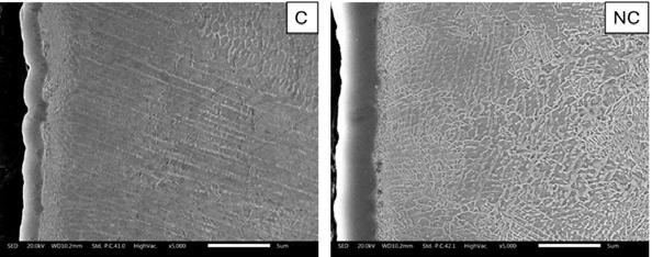
La figura 2 mostra la microstruttura della sezione degli strati superficiali dei campioni C ed NC. In entrambe le immagini è visibile il rivestimento Ti(C,N), più spesso nel campione NC, e lo strato di diffusione sottostante. Nella parte esterna dello strato di diffusione di NC è visibile una fine precipitazione aghiforme del nitruro Fe 4N. Questa precipitazione non è visibile nel campione C. La analisi XRD hanno confermato questo risultato [29].
La figura 3 mostra la microstruttura al cuore dei tra materiali studiati. Nel DAT si osserva la microstruttura di solidificazione che non è stata modificata dal trattamento di invecchiamento, caratterizzata dai bordi fra i primari grani di solidificazione e dalla substruttura cellulare molto fina. Dopo i trattamenti superficiali la struttura cellulare risulta parzialmente frammentata, e anche i bordi fra i grani pri-
mari non sono visibili chiaramente. L’analisi XRD ha rilevato una sensibile differenza nel contenuto di austenite: 9% in DAT, 14% in C e 27% in NC, determinata dall’esposizione dal materiale alla temperatura della nitrurazione e del trattamento PVD che promuove la formazione di ulteriore “reverted austenite”.

- Microstruttura SEM del cuore dei campioni analizzati: a) DAT, b) C, e c) NC.
I profili di microdurezza dei campioni trattati in superficie sono mostrati in figura 4. Il trattamento NC induce non solo una maggiore microdurezza superficiale ma anche una maggiore profondità dell’indurimento (150 μ m in confronto con 50 μ m) rispetto al trattamento C, come era
atteso data la notevole differenza dello stadio di nitrurazione. In entrambi i casi, il trattamento duplex aumenta notevolmente la microdurezza del materiale. La microdurezza a cuore del campione DAT è leggermente superiore a quella dei due trattati in superficie (650 HV0.025).
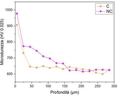
- Profili di microdurezza dei campioni C e NC.
La durezza HRc misurata sulla superficie e a cuore da i risultati riportati in figura 5. La durezza misurata in superficie è praticamente la stessa nei tre materiali, mentre a
cuore si osserva un calo minimo solo nel materiale NC. La maggiore quantità di austenite nei materiali trattati in superficie non ha un effetto significativo sulla durezza.
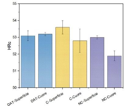
I risultati delle prove di impatto sono riportati in figura 6. Si osserva che la resistenza all’impatto è praticamente isotropa, ma soprattutto che, malgrado il notevole indu-
rimento superficiale, il trattamento superficiale non infragilisce il materiale in quanto le differenze osservate sono confrontabili con la deviazione standard dei risultati.

Per comprendere questo risultato, sono state ripetute le misure del profilo di microdurezza alla base dell’intaglio, cioè nella regione dove nuclea la cricca. I risultati sono confrontati con quelli ottenuti in corrispondenza della superficie dei pezzi (fig. 3) nella figura 7. Sia la microdurezza superficiale che la profondità dell’indurimento sono
molto inferiori alla base dell’intaglio, a causa dell’effetto geometrico della nitrurazione in plasma [30]. L’efficacia del trattamento infatti dipende dalla geometria dei pezzi, risultando maggiore sulle asperità e minore nelle valli in confronto con le regioni a superficie piana.
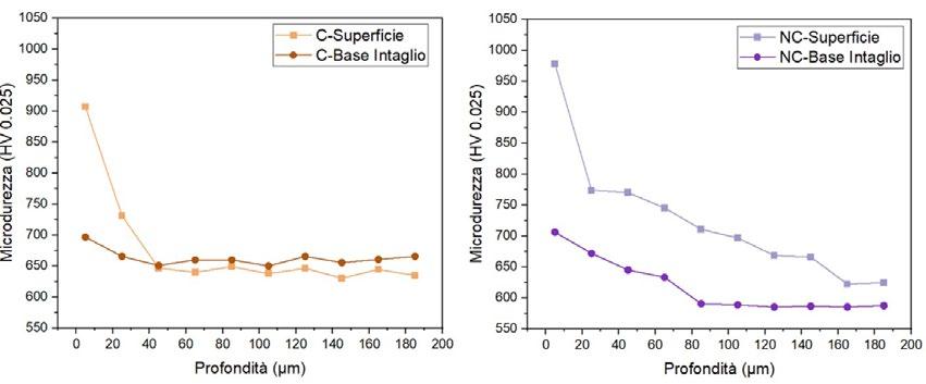
Fig.7 - Profili di microdurezza dei campioni C e NC in corrispondenza della superficie piana e della base dell’intaglio.
L’assenza di un effetto infragilente del trattamento di indurimento superficiale è quindi da attribuire alla minore intensità dell’indurimento stesso nella zona dove nuclea la cricca, in combinazione con l’aumento del contenuto di austenite.
Il risultato delle prove di fatica è riportato in figura 8.
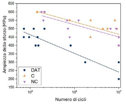
Fig.8 - Ampiezza dello sforzo in funzione del numero di cicli.
Il trattamento superficiale promuove un notevole miglioramento della resistenza a fatica rispetto al trattamento di invecchiamento, variabile dal 30% circa agli alti livelli di sforzo fino al 100% ai livelli più bassi (con riferimento alla retta interpolante del 50% di probabilità di frattura). Non si osserva una differenza fra i due trattamenti superficiali, malgrado il differente indurimento superficiale evidenziato dai profili di
microdurezza. L’effetto del trattamento superficiale è quello di spostare tendenzialmente il punto di innesco della frattura dalla superficie agli strati più interni, come evidenziato dall’osservazione delle superfici di frattura. Alcuni esempi sono riportati in figura 9, nella quale si osserva chiaramente la presenza del cosiddetto “killer defect” sulla superficie del campione DAT e all’interno nei campioni C e NC.

Fig.9 - Esempi superficie di frattura da fatica dei campioni DAT, C e NC.
CONCLUSIONI
Nel presente lavoro è stato studiato l’effetto di un trattamento superficiale duplex (nitrurazione in plasma seguita da PVD) sulla microstruttura, la resistenza all’impatto e la resistenza alla fatica assiale di un acciaio maraging 18Ni300 prodotto per L-PBF. Come riferimento è stato assunto lo stesso acciaio invecchiato direttamente, senza eseguire la solubilizzazione.
L’amento della durezza superficiale e sub-superficiale promosso dal trattamento di nitrurazione causa un notevole aumento della resistenza alla fatica senza indurre un calo della resistenza all’impatto. L’aumento della resistenza a fatica è dovuto allo spostamento della nucleazione della cricca negli strati più interni, tendenzialmente alla fine dello strato di diffusione. Non si osserva un effetto della diversa intensità della nitrurazione fra i due trat-
tamenti superficiali. L’assenza di un effetto negativo sulla resistenza all’impatto è attribuito non solo all’aumento del contenuto di austenite (reverted austenite), ma anche alla ridotta efficacia della nitrurazione alla base dell’intaglio delle barrette Charpy.
Ringraziamenti
Il Progetto di ricerca è finanziato dal Ministero per lo Sviluppo Economico, progetto n. F/050184/01-02/X32 del “Programma Operativo Nazionale Imprese e Competività” 2014-2020 FESR – Bando Horizon 2020 PON I&C 20142020.
[1] Bai Y, Yang Y, Wang D, Zhang M, l. Influence mechanism of parameters process and mechanical properties evolution mechanism of maraging steel 300 by selective laser melting, Mater Sci Eng A. 2017;703:116–123.
[2] Laleh M, Sadeghi E, Revilla RI, Chao Q, Haghdadi N, Hughes AE, Xu W, De Graeve I, Qian M, Gibson I, Tan MY. Heat treatment for metal additive manufacturing, Prog Mater Sci. 2023;133:101051.
[3] Tewari R, Mazumder S, Batra IS, Dey GK, Banerjee S. Precipitation in 18 wt% Ni maraging steel of grade 350, Acta Mater. 2000;48(5):1187–1200.
[4] Haghdadi N, Laleh M, Moyle M, Primig S. Additive manufacturing of steels: a review of achievements and challenges. Journal of Materials Science. 2021;56(1):64–107.
[5] Zenker R, Spies HJ, Buchwalder A, Sacher G. Combination of high energy beam processing with thermochemical treatment and hard protective coating: state of the art Int Heat Treat Surf Eng. 2007;1(4):152–155.
[6] Avelar-Batista JC, Godoy C, Mancosu RD, Janaina Morais AM. Plasma Nitriding and PAPVD Hard Coating: a Critical Overview of Duplex Coating Processing. Jornadas Sam/ Conamet/ Simposio Materia, 2003;06–50:600-603.
[7] Kempski L, Waechter Dias V, dos Santos GR, Torres RD, Hubler R, da Silva Rocha A. Investigation on Different TiCN Duplex Treatments Applied to Cold Work Tool Steel for Surface Properties Improvement J Mater Eng Perf. 2021;30(6):4445–4457.
[8] He JL, Chen KC, Davison A. Improvements in the understanding and application of duplex coating systems using arc plasma technology. Surf Coat Technol. 2005;200(5–6):1464–1471.
[9] Cajner F,, Landek D, Leskov V. Surface Modifications of Maraging Steels Used in the manufacture of moulds and dies. Mater Technol. 2010;44(1):85–91.
[10] Shetty K, Kumar S, Raghothama Rao P. Effect of ion nitriding on the microstructure and properties of Maraging steel (250 Grade). Surf Coat Technol. 2009;203(10–11):1530–1536.
[11] Selg H, Meka SR, Kachel M, Waldenmaier T, Mittemeijer EJ. Nitriding behaviour of maraging steel: Experiments and modellingJ Mater Sci. 2013;48:4321–4335.
[12] De Ara JF, Almandoz E, Palacio JF, Fuentes GG, Rodríguez RJ, García JA. Influence of temperature in arc-activated plasma nitriding of maraging steel in solution annealed and aged conditions Surf Coat Technol. 2014;258:754–762.
[13] Verdiere A, Hofer C, Waele SD, Bliznuka V, Primig S, Cotteniera S, Trane MD, Pennings B, Kestens,LAI, Petrov LH, Precipitation in simultaneously nitrided and aged Mo-containing maraging Steel Mater Charact. 2017;131:21–30.
[14] De Ara JF, Almandoz E, Palacio JF, Fuentes GG. Simultaneous ageing and plasma nitriding of grade 300 maraging steel: How working pressure determines the effective nitrogen diffusion into narrow cavities. Surf Coat Technol. 2017;317:64–74.
[15] Hong H, Dong DD, Lin SS, Wang W, Tang CM, Kuang TC, Dai MJ. Improving surface mechanical properties of the selective laser melted 18Ni300 maraging steel via plasma nitriding. Surf Coat Technol. 2021;406:126675.
[16] Simson T, Koch J, Rosenthal J, Kepka M, Zetek M, Zetková I, Wolf G, Tomčík P, Kulhánek J. Mechanical properties of 18Ni-300 maraging steel manufactured by LPBF. Proc Str Int., 2019;17:843–849.
[17] Kempen K, Yasa E, Thijs L, Kruth JP, Van Humbeeck J. Microstructure and mechanical properties of selective laser melted 18Ni-300 steel. Phis Proc. 2011;12(1):255–263.
[18] Bai Y, Wang D, Yang Y, Wang H. Effect of heat treatment on the microstructure and mechanical properties of maraging steel by selective laser melting. Mater Sci Eng A. 2019;760:105–117.
[19] Frank H, Ambos M, Lutze S, Scholz M. Improvement of the properties of additively manufactured steel parts by combination of heat treatment and hard coatings. IOP Conf Series: Mater Sci Eng. 2021;1147(1):012001.
[20] Yasa E, Deckers J, Kruth J, Rombouts M, Luyten J. Charpy impact testing of metallic selective laser melting parts.Virt Phys Prot. 2010;5(2):89–98.
[21] Tan C, Zhou K, Kuang M, Ma W, Kuang T. Microstructural characterization and properties of selective laser melted maraging steel with different build directions. Sci Techn Adv Mater. 2018;19(1):746–758.
[22] Podgornik B, Šinko M, Godec M. Dependence of the wear resistance of additive-manufactured maraging steel on the build direction and heat treatment. Add Manuf. 2021;46:102123.
[23] Croccolo D, De Agostinis M, Fini S, Olmi G, Vranic A, Ciric-Kostic S. Influence of the build orientation on the fatigue strength of EOS maraging steel produced by additive metal machine. Fatigue Fract Eng Mater Struct, 2016;39(5):637–647.
[24] Damon J, Hanemann T, Dietrich S, Graf G, Lang KH, Schulze V. Orientation dependent fatigue performance and mechanisms of selective laser melted maraging steel X3NiCoMoTi18-9-5. Int J Fatigue, 2019;127:395–402.
[25] Solberg K, Hovig EW, Sørby K, Berto F. Directional fatigue behaviour of maraging steel grade 300 produced by laser powder bed fusion. Int J Fatigue 2021;149:106229.
[26] Branco R, Silva J, Martins Ferreira J, Costa JD, Capela C, Berto F, Santos L, Antunes AF. Fatigue behaviour of maraging steel samples produced by SLM under constant and variable amplitude loading, Proc Struct Int 2019;22:10–16.
[27] Meneghetti G, Rigon D, Cozzi D, Waldhauser W, Dabalà E. Influence of build orientation on static and axial fatigue properties of maraging steel specimens produced by additive manufacturing. Proc Struct Int 2017;7:149–157.
[28] Meneghetti G, Rigon D, Gennari C. An analysis of defects influence on axial fatigue strength of maraging steel specimens produced by additive manufacturing. Int J Fatigue 2019;118:54–64.
[29] Elangeswaran C, Gurung K, Koch R, Cutolo R, Van Hooreweder B. Post-treatment selection for tailored fatigue performance of 18Ni300 maraging steel manufactured by laser powder bed fusion. Fatigue Fract Eng Mater Struct 2020;43(10)2359–2375.
[30] Tekin T, Maines L, Naclerio F, Ipek R, Molinari A, Effect of Duplex Surface Treatment on the Impact Properties of Maraging Steel Produced by Laser Powder Bed Fusion. Powd Metall doi.org/10.1177/00325899241253271.
[31] Dobrocky D, Kusmic D, The influence of the nitrided layer depth in the root of V-notch to notch toughness of 30CrMoV9 steel, Proceedings Metal 2015, Jun 3rd - 5th 2015, Brno, Czech Republic, https://www.researchgate.net/publication/281586908.
A. Santoni, M. Cabibbo, M. L. Gatto, G. Grima, E. Santecchia, K. Sleem, S. Spigarelli, M. Palladino
Il processo di Laser Powder Bed Fusion (L-PBF) si distingue nel settore del Metal Additive Manufacturing per la sua capacità di creare componenti metallici complessi attraverso la fusione strato su strato di polvere metallica tramite un fascio laser ad alta precisione. Questa tecnica è adatta alla produzione di strutture reticolari leggere e robuste, offrendo personalizzazione, efficienza nel trasferimento di calore e riduzione del peso e del consumo di materie prime. Le strutture Triply Periodic Minimal Surface (TPMS) rappresentano un avanzamento significativo, introducendo soluzioni innovative per la progettazione e la produzione ingegneristica. Lo studio è incentrato sull’analisi della fabbricabilità di provini lattice TPMS in Inconel 718 tramite L-PBF, con un focus sulla topologia di cella Gyroid. Sono state condotte simulazioni FEM L-PBF per analizzare distorsioni e tensioni residue. I provini as-built sono stati sottoposti a caratterizzazione meccanica e microstrutturale e a successivi trattamenti termici per studiarne gli effetti microstrutturali.
INTRODUZIONE
Con il termine Additive Manufacturing (AM) si intende un insieme di processi produttivi che, in contrasto con le tradizionali tecnologie sottrattive, permette la realizzazione di oggetti tridimensionali per deposizione di strati successivi di materiale (metallico e non), a partire da un file 3D CAD (Computer Aided Design) [1]. Secondo la definizione fornita dai comitati di regolamentazione ASTMF42 e ISOTC261, la fusione a letto di polvere (PBF) e la deposizione diretta di energia (DED) rappresentano le principali tecnologie di metal additive manufacturing (MAM). Questi processi si basano sulla fusione di materia prima, generalmente sotto forma di polvere micrometrica, che richiede una gestione accurata della materia prima e dei parametri di stampa. Dato che le cinetiche di reazione di tali processi additivi differiscono in modo sostanziale dalle tradizionali tecniche di produzione, raggiungendo velocità di raffreddamento dell’ordine dei 106 K/s, possono verificarsi una serie di effetti indesiderati, quali la formazione “incontrollata” di pori, l’elevata rugosità superficiale, la perdita di elementi in lega (volatilizzazione), l’innesco di cricche, l’eventuale delaminazione del componente durante e al termine del
A. Santoni, M. Cabibbo, M. L. Gatto, G. Grima, E. Santecchia, K. Sleem, S. Spigarelli
DIISM, Università Politecnica delle Marche, Ancona
M. Palladino
Baker Hughes, Firenze
processo di stampa e l’insorgere di elevate sollecitazioni residue che comportano la deformazione delle parti. La formazione di tali difetti è legata alla complessa storia termica risultante principalmente dai seguenti parametri di processo: velocità ed energia della fonte di calore, strategia del percorso di scansione, spessore dello strato e dimensione delle particelle di polvere [2]. Il processo di Laser Powder Bed Fusion (L-PBF) si distingue nel campo del MAM per la capacità di realizzare componenti metallici complessi, sfruttando la fusione di polvere metallica strato dopo strato, mediante un fascio laser ad alta precisione. Questa tecnica è particolarmente efficace per realizzare strutture reticolari (o “lattice”) leggere e resistenti, apportando benefici significativi in termini di personalizzazione, efficienza nel trasferimento di calore e riduzione del peso e del consumo di materie prime [3], [4]. Le strutture triply periodic minimal surface (TPMS) rappresentano un'evoluzione in questo ambito, offrendo soluzioni innovative per la progettazione e la produzione ingegneristica [5]. Lo scopo dello studio è valutare la fabbricabilità di provini lattice TPMS in Inconel 718 attraverso L-PBF, con particolare attenzione alla topologia della cella Gyroid [6], [7]. Sono state condotte simulazioni FEM per valutare i risultati della stampa 3D in termini di distorsioni e tensioni residue. Attraverso osservazioni e misurazioni effettuate tramite uno stereomicroscopio, sono state indagate le caratteristiche di deformazione dei provini reticolari. I campioni as-built sono stati sottoposti a caratterizzazione metallografica tramite microscopia ottica ed elettronica a scansione e a trasmissione (OM, SEM, TEM). Tramite le prove di microdurezza è stato possibile valutare le prestazioni meccaniche
del materiale. Successivamente, i reticoli sono stati sottoposti a trattamento termico di solubilizzazione e doppio invecchiamento (come delineato dalle specifiche dei materiali aerospaziali AMS 2774 e AMS 5662) per indagarne gli effetti microstrutturali.
In questo studio, il software nTopology è stato impiegato per modellare provini reticolari caratterizzati da un pattern di celle unitarie TPMS di tipo Gyroid. I campioni reticolari presentano parametri geometrici variabili della cella unitaria, come la dimensione della cella e lo spessore della parete (o “wall thickness”). Nella Fig. 1 (a) viene illustrato il modello 3D della cella unitaria. Nel dettaglio, sono stati modellati 3 provini reticolari variando di volta in volta il volume della cella unitaria sulla base di variazioni dei parametri geometrici, quali wall thickness e dimensione del lato della cella, come mostrato nella Tab. 1. Il reticolo presenta un ingombro di 8x8x8 mm. Ogni campione presenta una piastra superiore e una inferiore, con uno spessore rispettivamente di 3 mm e 0.8 mm. Pertanto, le strutture reticolari non sono state fabbricate direttamente sulla piattaforma di costruzione, per garantire un'adeguata dissipazione del calore durante il processo produttivo tramite la piastra inferiore.
La Fig. 1 (b) mostra i modelli CAD dei provini reticolari, a ciascuno dei quali è stato assegnato un codice identificativo come elencato nella Tab. 1.

Sulla base dei risultati ottenuti dalla stampa in termini di difetti e danneggiamenti riscontrati nelle strutture as-built, il solo campione c2 è stato sottoposto a caratterizzazione meccanica e metallografica.
Le simulazioni FEM del processo di stampa del campione C2 sono state condotte per valutare il risultato della stampa 3D utilizzando tecniche di prototipazione virtuale. Il software utilizzato per simulare il processo LPBF è Ansys Additive suite Workbench2020 R1 (Ansys® Workbench2020 R1). Per essere più precisi, questo software facilita le simulazioni di produzione condotte in condizioni variabili. Queste condizioni possono includere
una simulazione puramente meccanica, che stima le deformazioni risultanti dagli effetti termici utilizzando parametri predefiniti, o una simulazione che incorpora esplicitamente i fenomeni termici. Ansys utilizza il file STL nominale del modello CAD e i parametri del processo LPBF come input. Per avviare la simulazione, il modello viene suddiviso in voxel. Le simulazioni condotte in questo studio si basano sulle impostazioni fondamentali del software, come mostrato nel dettaglio nella Tab. 2.
- Impostazione dei parametri di simulazione / Setting of simulation parameters
Materiale Inconel 718
Layer thickness
Potenza laser
Velocità di scansione
μm
W
mm/s
Hatch distance 0.11 mm
Dimensioni dei voxel per il provino 0.2 mm
Dimensioni dei voxel per il piatto 4 mm
Nel dettaglio, le simulazioni effettuate hanno considerato le seguenti fasi: stampa, raffreddamento e taglio del pezzo dalla piastra di costruzione, al fine di verificare qualitativamente che il modello virtuale in Ansys restituisca valori di deformazione e di tensione residua comparabili con quelli reali. I moduli del modello di simulazione sviluppato in Ansys Workbench Additive sono illustrati nella Fig. 2.
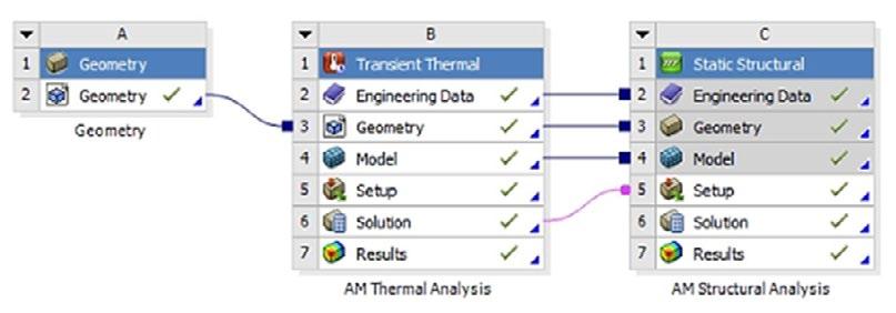
Fig.2 - Modello di simulazione in Ansys Workbench Additive / Simulation model in Ansys Workbench Additive. I campioni sono stati fabbricati utilizzando un'apparecchiatura EOS M250 LPBF, impiegando polvere atomizzata di Inconel 718 come materiale di partenza. Nella seguen-
te tabella (Tab. 3) viene riportata la composizione chimica espressa in peso percentuale (wt. %) dell’Inconel 718, così come fornita dal datasheet tecnico EOS [8].
Tab.3 - Composizione chimica (in peso %) della materia prima di Inconel 718 / Chemical composition (wt. %) of the Inconel 718 feedstock [8].
Peso percentuale wt. -% (Min./Max.)
Il processo LPBF è stato eseguito con potenza del laser e velocità di scansione secondo il modello di scansione core-skin predefinito, come mostrato nella Tab. 2, dove vengono riportati i valori dei parametri di processo impostati non solo per la simulazione ma anche per la stampa dei provini. È stato utilizzando uno spot del laser di 0,08 mm, e un'atmosfera di gas inerte stabilita con argon. Il riscaldamento della piattaforma di costruzione è stato impostato a 80 °C.
Per confrontare il componente prodotto con il modello simulato, sono state effettuate osservazioni del profilo del piatto superiore e misurazioni utilizzando uno stereomicroscopio Leica (modello DVM6) per valutare l’andamento e l'entità delle distorsioni lungo la direzione di crescita (direzione Z) causate dal processo di produzione. Sono stati estratti due campioni metallografici tagliando a metà il provino c2 lungo la direzione di crescita (piano YZ) mediante elettroerosione (EDM). Un campione è stato lasciato allo stato as-built, mentre l’altro è stato sottoposto a trattamento termico per investigare le differenze nel comportamento meccanico e microstrutturale tra le
due condizioni. Nello specifico, è stato effettuato un trattamento termico di solubilizzazione seguito da doppio invecchiamento, come delineato dalle specifiche dei materiali aerospaziali AMS 2774 e AMS 5662 [8]. In particolare, il processo prevede un riscaldamento fino a 954°C per 1 ora, raffreddamento in aria, seguito da una seconda fase di riscaldamento a 718°C, con un tempo di permanenza di 8 ore a tale temperatura. Successivamente, viene eseguito un ulteriore raffreddamento in forno fino a 621°C, con una permanenza a 621°C per un tempo totale di precipitazione di 18 ore e, infine, raffreddamento in aria fino a temperatura ambiente.
Per l'indagine metallografica, le superfici YZ dei campioni as-built (c2-AB) e trattato termicamente (c2-HT) sono state lucidate meccanicamente con carte abrasive al carburo di silicio fino a 4000 grit, successivamente lucidate a specchio con pasta diamantata fino a 0,25 μ m. Per caratterizzare la microstruttura della lega prima e dopo il trattamento termico, i campioni sono stati sottoposti ad attacco chimico a temperatura ambiente, utilizzando la seguente soluzione: 28 ml di acido acetico, 28 ml di acido nitrico,
44 ml di acido cloridrico. Le osservazioni al microscopio ottico sono state eseguite con un'apparecchiatura Leica DMi8 per evidenziare le caratteristiche microstrutturali. Per caratterizzare più nel dettaglio la microstruttura dell'Inconel 718 prodotto con LPBF e la sua evoluzione in seguito ai trattamenti termici, sono state eseguite delle analisi al microscopio elettronico a scansione (SEM) utilizzando un microscopio Zeiss Supra 40 a emissione di campo, dotato di un sistema di microanalisi Bruker Quantax Z200. La caratterizzazione TEM è stata effettuata mediante microscopia elettronica a trasmissione utilizzando un Philips CM200, che opera a 200 kV, dotato di un porta-campioni a doppia inclinazione raffreddato ad azoto. L'identificazione delle fasi e dei costituenti è stata eseguita tramite indicizzazione della diffrazione elettronica a zona selezionata (SAEDP). L'indicizzazione è stata effettuata con l'ausilio del software CaRIne Crystallography 3.1. I dischi sottili per il TEM sono stati preparati meccanicamente mediante lucidatura, assottigliamento da entrambi i lati del disco fino a 25-35 μ m con successiva fresatura ionica, utilizzando un Gatan PIPS che opera con Ar+ a angoli di incidenza progressivamente decrescenti da 8° fino a 4° per ottenere un volume del disco TEM sufficientemente ampio per la trasparenza elettronica. Per ottenere risultati statisticamente affidabili tramite analisi TEM, sono stati
ispezionati tre dischi diversi per ciascuna condizione sperimentale.
Sono state condotte delle misure di microdurezza Vickers su entrambi i campioni AB e HT tramite un microdurometro automatico QNESS 60 A+ EVO, con un carico applicato di 300 gF e un tempo di permanenza di 10 secondi, al fine di caratterizzare il comportamento meccanico locale in diverse posizioni sulla superficie in esame. Le misure sono state eseguite con le stesse condizioni sul piatto superiore di ciascun campione, in particolare, sono state effettuate tre indentazioni sistematiche ogni 0,5 mm per 15 volte nel piano YZ (Fig. 3 (a)), coprendo l'intero spazio sulla superficie del piatto. Inoltre, sono state effettuate ulteriori prove di microdurezza Vickers lungo le pareti del reticolo (in Fig. 3 (b) viene riportata una rappresentazione schematica delle impronte lasciate sul provino) al fine di investigare eventuali variazioni nelle proprietà meccaniche rispetto al materiale massivo del piatto superiore e valutare come il trattamento termico abbia influito sulle caratteristiche meccaniche della struttura lattice in termini dei valori di microdurezza ottenuti. Al termine dell'analisi condotta su entrambi i campioni nelle medesime condizioni, è stato riportato il valore medio ottenuto, con la sua deviazione standard.
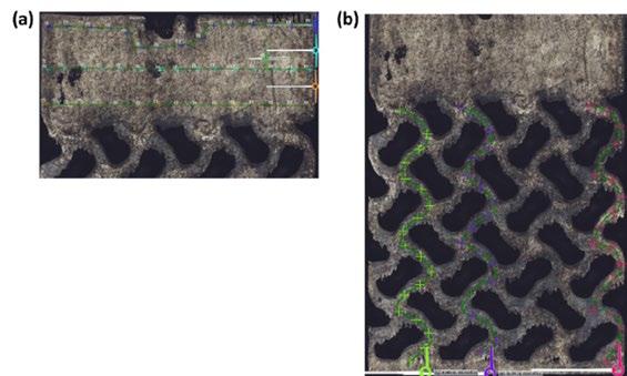
Fig.3 - appresentazione schematica delle misure di microdurezza lungo il piano YZ in prossimità (a) del piatto superiore e (b) della struttura reticolare / Schematic representation of the microhardness measurements along the YZ plane of (a) the upper plate and of (b) the lattice structure.
Nella Fig. 4 sono presentati i risultati dell'analisi FEM condotta mediante il software Ansys® Workbench2020 R1, espressi in termini di deformazioni direzionali, misurate lungo la direzione z, al termine della fase di stampa e successivo raffreddamento e dopo la rimozione del componente dal piatto di stampa. Nella Fig. 4 (a) vengono riportati i marcatori con i valori massimi di deformazione direzio-
nale (espressi in mm) misurati nella regione di interfaccia tra la struttura reticolare ed il piatto superiore, vicino ai bordi di quest'ultimo, dove è evidente una notevole distorsione del piatto, che tende ad inarcarsi verso l’alto. Il valore massimo di deformazione direzionale misurato è di 0.318 mm. Il valore massimo dello stress raggiunto dopo la rimozione del campione dal piatto di stampa è intorno
ai 1000 MPa e si trova nell'area di interfaccia tra la struttura reticolare ed il piatto superiore, identificato dal valore numerico come illustrato nella Fig. 4 (b). Tale valore è comunque accettabile dal momento che non supera il limite di snervamento dell'Inconel 718, che può variare tra 724 MPa e 1241 MPa.
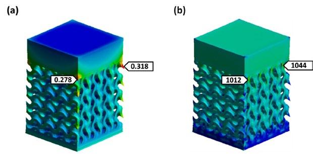
Fig.4 - (a) Deformazione massima direzionale (lungo z) espressa in mm e (b) stress equivalente di Von Mises espresso in MPa, una volta rimosso il provino dal piatto di stampa / (a) Maximum directional deformation (along z) expressed in mm and (b) Von Mises equivalent stress expressed in MPa, after removing the sample from the build plate
Il confronto tra il modello simulato e la geometria stampata è stato effettuato tramite osservazioni allo stereomicroscopio, estraendo il profilo di deformazione di una porzione del piatto superiore e misurando gli scostamenti direzionali in alcuni punti del piatto superiore lungo il piano XY. I risultati, riportati nella Fig. 5, mostrano una sostanziale sovrapposizione tra il modello simulato e il componente reale riguardo il trend di deformazione e i valori numerici delle deformazioni direzionali (lungo l’as-
se Z) misurate in prossimità del piano XY del piatto superiore, confermando l'affidabilità del software utilizzato. Si osserva una leggera curvatura del piatto verso la direzione Z negativa, risultando in una compressione della superficie superiore. Dall'area centrale verso i bordi del piatto si verifica un'inversione di tendenza nei valori di deformazione. L'entità della deformazione è stata misurata in punti specifici del piatto nel modello simulato (Fig. 5 (a)) e nei corrispettivi punti del provino reale (Fig. 5 (b)).
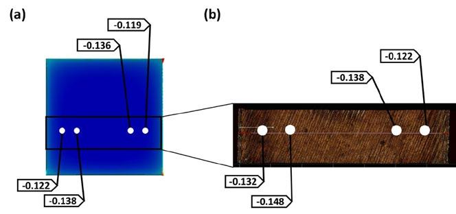
Fig.5 - Confronto tra (a) il modello Ansys e (b) la geometria reale (misurazioni allo stereomicroscopio) in termini di deformazioni direzionali espresse in mm (lungo l’asse Z) del piatto superiore / Comparison between a) Ansys model and b) real geometry (stereomicroscope measurements) in terms of directional deformation expressed in mm (along the Z-axis) of the upper plate.
In Fig. 6 (a), la microstruttura del provino c2-AB mostra la forma ad arco delle pozze di fusione create dal laser durante la scansione del letto di polvere, con sovrapposizioni parziali dovute alla rotazione del fascio laser di 67° per ogni passata. La dissipazione del calore dalla zona fusa alla piattaforma porta alla formazione di grani colonnari allineati lungo l'asse Z, visibili a bassi ingrandimenti, che attraversano strati successivi di polvere grazie alla rifusione multipla e alla crescita epitassiale. Fig. 6 (b) mostra la microstruttura del campione c2-HT, evidenziando una par-
ziale ricristallizzazione indotta dal trattamento termico, con scomparsa delle pozze fuse ma solo parziale dissoluzione delle strutture dendritiche. La ricristallizzazione statica forma grani colonnari lungo l'asse Z, ma la temperatura non è sufficiente a promuovere la formazione di grani equiassici. Il trattamento termico produce effetti simili sia sul reticolo che sul piatto in termini di proprietà microstrutturali.

Fig.6 - Micrografie ottiche della microstruttura del piatto superiore (lungo il piano YZ) dei campioni (a) c2-AB e (b) c2-HT / Optical micrographs depicting the microstructure of the upper plate (along the YZ plane) of samples a) c2-AB and b) c2-HT.
In Fig. 7 (a) viene illustrata un'immagine SEM a basso ingrandimento del campione c2-AB che mostra una microstruttura cellulare-dendritica molto fine, in cui la crescita delle ramificazioni secondarie delle strutture dendritiche è completamente soppressa e si sviluppano solo le ramificazioni primarie. Come si può evincere sia dalla micrografia in Fig. 6 (a) che dall’immagine SEM in Fig. 7 (a), le direzioni di crescita delle dendriti non sono perfettamente parallele alla direzione di costruzione, ma invece inclinate di alcuni gradi rispetto ad essa. Inoltre, le dendriti cellulari possono crescere in direzioni diverse all'interno di una singola pozza di fusione e persino essere interrotte dalle dendriti cellulari adiacenti, come osservato anche in letteratura da uno studio condotto da Deng et al. [9]. La variazione nelle dimensioni e nell'orientamento delle sottostrutture cellulari di solidificazione è indotta dall'elevato gradiente di temperatura e dall'elevata velo-
cità di raffreddamento generati durante il processo LPBF. Di conseguenza, l'orientamento di crescita delle dendriti ruota verso la direzione di massimo gradiente termico. Ciò suggerisce che il campo di temperatura all'interno della pozza di fusione è estremamente complesso e si innesca un moto turbolento con conseguente inversione del gradiente termico. La Fig. 7 (b) è un'immagine acquisita al TEM in campo chiaro (BF) che mostra sottili sottostrutture cellulari con un'alta densità di dislocazioni osservate nelle pareti delle celle nel campione c2-AB. I precipitati scuri di forma irregolare a blocchi presenti in prossimità dei bordi dei grani, evidenziati dalle frecce nella Fig. 7 (b), sono stati identificati come fasi di Laves.
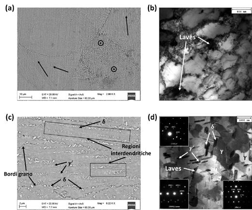
Fig.7 - Immagini SEM della microstruttura dei campioni (a) c2-AB e (c) c2-HT e immagini TEM della microstruttura dei campioni (b) c2-AB e (d) c2-HT, lungo il piano YZ / SEM images of the microstructure of samples (a) c2-AB and (c) c2-HT, and TEM images of the microstructure of samples (b) c2-AB and (d) c2-HT, along the YZ plane.
Nell’immagine al SEM riportata nella Fig. 7 (c) è possibile valutare come nel campione c2-HT rispetto al campione c2-AB, i confini delle pozze di fusione e molte microstrutture dendritiche direzionali sono state dissolte. Una quantità di fasi δ (Ni3Nb) aghiformi è presente all'interno dei grani e ai confini dei grani, e alcune sono precipitate nelle regioni interdendritiche (indicate dai rettangoli neri nella Fig. 7 (c)). Ciò è in linea con quanto osservato nello studio condotto da Li et al. [10]. La formazione di precipitati δ interdendritici consente alla trama colonnare intragranulare di rimanere visibile dopo il trattamento termico.
Dall’immagine SEM è possibile osservare la presenza di altre fasi precipitate, probabilmente corrispondenti alle fasi γ ’ (Ni3 (Al, Ti)), che potrebbero precipitare nella matrice γ sia all’interno dei grani che in prossimità dei bordi di grano. La fase γ ’ precipita con una morfologia aciculare. Le fasi γ ’ agiscono come rinforzi all'interno della matrice gamma, mentre le fasi δ , precipitando ai bordi di grano, costituiscono barriere fisiche al movimento delle dislocazioni, aumentando così la resistenza alla deformazione a temperature elevate e sotto carichi sostenuti nel tempo. La presenza di fasi di Laves non completamente dissolte nella matrice può influire negativamente sulle proprietà meccaniche per due motivi principali: in primo luogo, consumano il contenuto di Nb, riducendo il potenziale per la precipitazione delle fasi rinforzanti γ ' e γ "; in secondo luogo, le fasi di Laves agiscono come siti di iniziazio-
ne per la propagazione delle cricche, compromettendo l'integrità strutturale e accelerando il guasto in servizio. Questi risultati in termini di fasi precipitate osservate nel campione c2-HT sono parzialmente in accordo con i risultati presentati nei lavori di ricerca di Li et al. [10], Li at al. [11] e Zhang et al. [12]. Pertanto, questa microstruttura non può essere considerata ideale. La micrografia TEM in Fig. 7 (d), insieme ai relativi pattern di diffrazione SAED riportati come inserti nell’immagine, confermano l'identificazione delle fasi precipitate. Questo metodo è cruciale per distinguere le fasi in base alla loro struttura cristallina, essendo molte delle fasi precipitate osservate al SEM simili dal punto di vista morfologico e composizionale.
Le strutture cellulari evidenziate sia con colori chiari che scuri nella Fig. 7 (b) rappresentano la matrice γ , ma con diverse orientazioni cristallografiche.
La caratterizzazione della microdurezza Vickers è stata eseguita nel piano YZ sia sul campione c2-AB che su quello c2-HT, al fine di valutare come il trattamento termico di solubilizzazione e doppio invecchiamento influenzi le prestazioni meccaniche del materiale. Per ciascun campione, le misurazioni sono state effettuate sul piatto superiore e sulla struttura reticolare. La Fig. 8 mostra i profili di microdurezza ( µ HV, 300 gf) per il campione c2-AB relativi al piatto superiore ((Fig. 8 (a)) lungo la direzione di crescita (piano YZ), evidenziando notevoli differenze tra questo campione e quello c2-HT (Fig. 8 (b)).
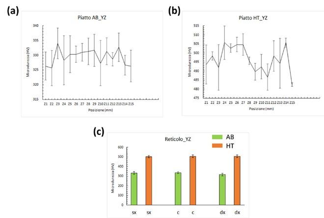
Fig.8 - Profili di microdurezza HV (300 gf) del piatto superiore raccolti nella direzione di crescita (a) prima (c2-AB) e (b) dopo (c2-HT) il trattamento termico. Confronto tra i valori medi di microdurezza con le rispettive deviazioni standard ottenuti lungo il piano YZ sia per il campione c2-AB che c2-HT calcolati sul reticolo in prossimità delle pareti esterne (sx e dx) e della parete centrale (c) / HV microhardness profiles (300 gf) of the upper plate collected in the growth direction (a) before (c2-AB) and (b) after (c2-HT) the heat treatment. (c) Comparison between the average microhardness values with their respective standard deviations obtained along the YZ plane for both the c2-AB and c2-HT samples, calculated on the lattice near the outer walls (left and right) and the central wall (c).
Per il campione c2-AB, lungo la direzione di crescita, il valore medio di microdurezza misurato sul piatto superiore varia tra 313 e 346 HV, con valori leggermente più alti vicino al bordo superiore e nella zona di interfaccia con la struttura reticolare, mentre tendono a diminuire verso il nucleo del piatto. D'altra parte, il valore medio di microdurezza valutato sul piatto del campione c2-HT varia tra 479 e 526 HV. La deviazione standard associata ai valori di microdurezza è maggiore nel campione c2-AB prodotto rispetto al campione trattato termicamente a causa di una microstruttura meno omogenea, tensioni residue significative, difetti introdotti dal processo di stampa, e fluttuazioni termiche locali. Il trattamento termico uniforma la microstruttura, rilassa le tensioni residue e riduce i difetti, risultando in una minore variabilità e quindi in una deviazione standard inferiore nei valori di microdurezza. Per quanto riguarda il campione c2-AB, i valori medi di microdurezza misurati lungo le superfici del reticolo hanno restituito valori compresi tra 328 e 358 HV. Per il campione trattato termicamente, invece, sono stati ottenuti valori medi di microdurezza compresi tra 486 e 522 HV in corrispondenza del reticolo. Nella Fig. 8 (c) viene
riportato il grafico a colonne con i valori medi di microdurezza e relativa deviazione standard misurati lungo tre pareti del reticolo (una centrale e le altre prossime ai bordi esterni) lungo il piano YZ prima e dopo trattamento termico. L'aumento della durezza osservato nel campione HT rispetto alla condizione AB è principalmente dovuto all'elevata quantità di fasi precipitate dopo il trattamento termico, che ha significative conseguenze sulle proprietà meccaniche del materiale, risultando in una bassa duttilità e aumento della durezza. Questi precipitati, come già visto nelle micrografie TEM (Fig. 7 (d)), possono essere attribuiti alle fasi δ , ma soprattutto alle fasi γ ’ che possono precipitare rispettivamente durante la fase di doppio invecchiamento a 718 °C e 621 °C, rafforzando così il materiale e migliorando di conseguenza le sue proprietà meccaniche, come la durezza. Risultati simili sono stati riscontrati nei lavori di ricerca di Deng et al. [9] e Zhang et al. [12]. Inoltre, Chamanfar et al. [13] hanno scoperto che una piccola quantità di fasi δ inibirebbe la crescita del grano bloccando i bordi dei grani, aumentando così la resistenza e la durezza attraverso il rafforzamento del grano. Tuttavia, la resistenza diminuirebbe se la lega contenesse
troppe fasi δ , poiché la formazione delle fasi δ consuma Nb inibendo la precipitazione delle fasi di rafforzamento γ ”.
Nel presente studio è stata indagata la fabbricabilità tramite LPBF di provini reticolari con topologia di cella TPMS di tipo Gyroid. In virtù delle caratteristiche geometriche, tra le combinazioni di provini reticolari a densità variabile, è stato sottoposto soltanto il provino c2 a caratterizzazione meccanica e microstrutturale. Sono state condotte analisi FEM tramite Ansys del processo LPBF per dimostrare l’efficacia del software nella previsione delle deformazioni generate durante il processo di stampa e una volta rimosso il componente dalla piattaforma di costruzione. La corrispondenza tra il modello simulato e le misurazioni effettuate sulle immagini acquisite allo stereomicroscopio, in termini di valori numerici delle deformazioni misurate in una regione del piatto superiore sia del modello virtuale che del componente reale, ha confermato l'affidabilità del software di simulazione. Il campione c2 è stato sottoposto a trattamento di solubilizzazione e doppio invecchiamento. L'analisi metallografica dei campioni c2-AB e c2HT, utilizzando la microscopia ottica (OM), la microscopia elettronica a scansione (SEM) e la microscopia elettronica a trasmissione (TEM), insieme alla valutazione delle prestazioni meccaniche tramite prove di microdurezza Vickers, ha portato alle seguenti osservazioni:
• Evoluzione microstrutturale: Le condizioni post-trattamento termico non sono state sufficienti per una com-
pleta ricristallizzazione vicino al reticolo. Sebbene si sia verificata un'iniziale omogeneizzazione, il materiale mostra ancora tracce di strutture dendritiche non completamente dissolte in alcune aree, sia in corrispondenza del piatto superiore che della struttura reticolare.
• Fasi precipitate: Le immagini acquisite al SEM e al TEM hanno identificato le principali fasi precipitate dopo il trattamento termico: γ ' e δ . Sono state rilevate alcune fasi di Laves non disciolte, che potrebbero influenzare la duttilità e la resistenza meccanica del componente. Dovrebbero essere considerati temperature di trattamento di solubilizzazione più elevate o ulteriori trattamenti di omogeneizzazione.
• Analisi della microdurezza: Le prove di microdurezza
Vickers hanno mostrato una maggiore durezza nei campioni HT rispetto ai campioni AB, attribuita alla precipitazione delle fasi di rinforzo. I campioni HT hanno mostrato una distribuzione della durezza più omogenea, con il trattamento termico che contribuisce a una risposta meccanica uniforme e a una maggiore durezza grazie alle fasi di precipitazione γ ' e δ .
Questa ricerca è stata finanziata parzialmente attraverso il progetto Dipartimento di Eccellenza, MIUR-Italy (ARTICOLO 1, COMMI 314–337 LEGGE 232/2016). Si ringrazia per la collaborazione l’azienda Baker Hughes di Firenze.
[1] Gadagi, B., & Lekurwale, R. (2021). A review on advances in 3D metal printing. Materials Today: Proceedings, 45, 277-283. https://doi. org/10.1016/j.matpr.2020.10.436
[2] DebRoy, T., Wei, H. L., Zuback, J. S., Mukherjee, T., Elmer, J. W., Milewski, J. O., & Zhang, W. (2018). Additive manufacturing of metallic components–process, structure and properties. Progress in materials science, 92, 112-224. https://doi.org/10.1016/j. pmatsci.2017.10.001
[3] Tamburrino, F., Graziosi, S., & Bordegoni, M. (2018). The design process of additively manufactured mesoscale lattice structures: a review. Journal of Computing and Information Science in Engineering, 18(4), 040801. https://doi.org/10.1115/1.4040131. https://doi. org/10.1115/1.4040131
[4] Maconachie, T., Leary, M., Lozanovski, B., Zhang, X., Qian, M., Faruque, O., & Brandt, M. (2019). SLM lattice structures: Properties, performance, applications and challenges. Materials & Design, 183, 108137. https://doi.org/10.1016/j.matdes.2019.108137.
[5] Maskery, I., Aboulkhair, N. T., Aremu, A. O., Tuck, C. J., & Ashcroft, I. A. (2017). Compressive failure modes and energy absorption in additively manufactured double gyroid lattices. Additive Manufacturing, 16, 24-29. https://doi.org/10.1016/j.addma.2017.
[6] Akca, E., & Gürsel, A. (2015). A review on superalloys and IN718 nickel-based INCONEL superalloy. Periodicals of engineering and natural sciences, 3(1). https://dx.doi.org/10.21533/pen
[7] Carter, L. N., Attallah, M. M., & Reed, R. C. (2012). Laser powder bed fabrication of nickel-base superalloys: influence of parameters;
characterisation, quantification and mitigation of cracking. Superalloys, 2012(6), 2826-2834. https://doi.org/10.1002/9781118516430. ch64
[8] EOS Nikel Alloy IN718 Material Data Sheet.
[9] Deng, D., Peng, R. L., Brodin, H., & Moverare, J. (2018). Microstructure and mechanical properties of Inconel 718 produced by selective laser melting: Sample orientation dependence and effects of post heat treatments. Materials Science and Engineering: A, 713, 294-306. https://doi.org/10.1016/j.msea.2017.12.043
[10] Li, X., Shi, J. J., Wang, C. H., Cao, G. H., Russell, A. M., Zhou, Z. J., & Chen, G. F. (2018). Effect of heat treatment on microstructure evolution of Inconel 718 alloy fabricated by selective laser melting. Journal of Alloys and Compounds, 764, 639-649. https://doi. org/10.1016/j.jallcom.2018.06.112
[11] Li, J., Zhao, Z., Bai, P., Qu, H., Liu, B., Li, L., & Guo, Z. (2019). Microstructural evolution and mechanical properties of IN718 alloy fabricated by selective laser melting following different heat treatments. Journal of Alloys and Compounds, 772, 861-870. https://doi. org/10.1016/j.jallcom.2018.09.200
[12] Zhang, D., Niu, W., Cao, X., & Liu, Z. (2015). Effect of standard heat treatment on the microstructure and mechanical properties of selective laser melting manufactured Inconel 718 superalloy. Materials Science and Engineering: A, 644, 32-40. https://doi. org/10.1016/j.msea.2015.06.021
[13] Chamanfar, L. Sarrat, M. Jahazi, M. Asadi, A. Weck, A.K. Koul, Microstructural characteristics of forged and heat treated Inconel-718 disks, Mater. Des. 52 (2013) 791e800. https://doi.org/10.1016/j.matdes.2013.06.004
L. Fabiocchi, M. Mariani, A. Lucchini Huspek, M. Pozzi, M. Bestetti, S. Graziosi, N. Lecis
This study presents an investigation into the mechanical and tribological properties of binder jetting 17-4PH (AISI 630) stainless steel, with a focus on the interplay between surface finishing and thermal treatments. A subset of samples was superficially treated with a Low Energy High Current Electron Beam, varying the energy density (J/cm2), whereas another set of specimens was thermally treated by solution annealing and aging (H900). Experimental analyses included visual inspection, roughness measurements, microhardness testing, and wear tests. Optical microscopy provided insights into the surface morphology and treatment-dependent defects. Roughness measurements quantified the surface texture alterations, while microhardness tests determined the effect of treatments on the mechanical properties of the material. Tribological tests evaluated the sample wear resistance and the material behaviour during sliding. Analysis of wear behaviour correlated with specific surface finishing or thermal treatments aimed to distinguish their effects on friction coefficients and wear track morphology across samples.
KEYWORDS:
Additive manufacturing (AM) of stainless steels is rapidly developing thanks to the ability to achieve complex designs effortlessly. This capability is relevant in industrial sectors where limited-scale production coupled with customization is demanded, such as the biomedical field: prostheses as well as surgical instruments tailored to the users’ needs, would greatly benefit from enhancement in terms of dimensional accuracy, functionality, and weight reduction. Among different techniques, binder jetting (BJT) is emerging owing to the possibility of using specific alloys employed in this sector (e.g. stainless steels, titanium, CoCrMo). This process yields final microstructures akin to those produced through conventional manufacturing processes, especially those associated with sinter-based approaches. When utilized for 17-4 PH stainless steel (AISI 630), a martensitic precipitation-hardening alloy, BJT provides notable benefits in terms of scalability and cost reduction. The technique works by depositing a binder onto layers of metal powder, forming a green part that is later sintered to achieve the desired mechanical properties. For 17-4 PH steel, crucial post-processing steps, including debinding, sintering, and heat treatments, are necessary to achieve the optimal mechanical characteristics such
L. Fabiocchi, M. Mariani, S. Graziosi, N. Lecis
Dipartimento di Meccanica, Politecnico di Milano
A. Lucchini Huspek, M. Bestetti
Dipartimento di Chimica, Materiali e Ingegneria Chimica
“Giulio Natta”, Politecnico di Milano
M. Pozzi
Dipartimento di Chimica, Materiali e Ingegneria Chimica
“Giulio Natta”, Politecnico di Milano – Rösler Italiana s.r.l. lorenza.fabiocchi@polimi.it
as strength, hardness, and corrosion resistance. This approach is opening new routes for the production of high-performance components with complex designs even in the case of materials with low machinability, such as 17-4PH, that hinders the manufacturing of geometries without the aid of expensive tools and processes [1].
The surface characteristics of binder jetted components are critical to their performance, particularly in applications requiring high precision and durability in demanding environments. Key surface properties such as roughness, porosity, and microstructure significantly influence the wear resistance, fatigue life, and corrosion behaviour of these parts. Since BJT often produces components with relatively high surface roughness compared to machining subtractive manufacturing, additional finishing processes like polishing, machining, or coating are often required to enhance the surface quality. Moreover, the surface characteristics can have a profound impact on the mechanical performance, especially in applications that demand high reliability and precision. Therefore, optimizing surface properties is essential to ensure the functional success of binder jetted components [2,3].
Low Energy High Current Electron Beam (LEHCEB) technology has emerged as a viable surface finishing solution for binder jetted components, particularly for 17-4 PH stainless steel parts. This technique uses short (2.5 μ s), intense pulses (1 – 6 J/cm 2) of electron beams to rapidly melt and modify a thin surface layer ( ̴10 μ m), resulting in a smoother, more refined finish. LEHCEB reduces surface roughness, minimizes porosity, and improves microstructural uniformity which in turn enhances mechanical and tribological properties such as hardness and wear resistance. Additionally, this treatment can improve corrosion resistance by refining the grain structure and eliminating surface imperfections. Since LEHCEB does not modify the bulk properties of the material, it is an efficient and precise technique for improving surface quality in binder jetted parts, especially those used in high-performance applications. Nonetheless, it should be considered that the heat and the residual stresses generated by the process may induce microstructural changes in the sub-surface regions, especially in a temperature-sensitive alloy. Indeed, given the high copper concentrations in 17-4PH steel, the material properties can be widely adjusted by thermal
aging through precipitation hardening treatments: copper precipitates form within the supersaturated martensite grains, at first as coherent BCC clusters, then they grow into incoherent FCC phases. The nucleation of the Cu precipitates, as well as their coalescence, depends on the aging treatment conditions [4,5].
This study aims to determine the effect of LEHCEB treatment on the microstructural properties of the surface region and the tribological performance of 17-4PH steel components produced by BJT. The effectiveness of this surface finishing is assessed by comparison with the bulk and surface microstructural properties and wear resistance of as-sintered and thermally aged components.
MATERIALS AND METHODS
Sample preparation
The samples were manufactured with a Desktop Metal Shop System employing a pre-alloyed gas atomized powder with a D90 of 50 μ m and a layer thickness of 75 μ m. A commercial aqueous-based binder containing polyethylene glycol monomers was used in this study.
After the BJT process, the powder bed was cured in a natural convection air furnace at 180 °C for 6 hours to polymerize the binder and strengthen the green parts. The debinding and sintering treatments were performed in a single cycle in a slightly reducing atmosphere (97% Ar / 3% H2) to remove most of the organic binder and achieve a satisfactory densification of the material, while avoiding the oxidation of the components surface [6]. The samples were cooled in the furnace at a low rate until room temperature was achieved.
After sintering, a conventional H900 aging treatment at 480 °C for 1 hour was applied to the specimens, after an initial solution annealing cycle at 1050 °C for 1 hour. To avoid the oxidation of the surface, both treatments were realized in sequence in a low vacuum atmosphere with N2-assisted rapid cooling.
The Low-Energy High-Current Electron Beam (LEHCEB) surface was performed in a RITM-SP facility. Irradiation pressure was set at 1.8·10-4 torr with Ar as background gas. Two different accelerating voltage, 20 and 30 kV, were investigated, corresponding to an energy density value of 2.5 and 4.6 J/cm2, respectively. The applied number of pulses was 20 with a repetition frequency of 0.2 Hz. After LEHCEB irradiation samples were cooled down within
the vacuum chamber in saturated Ar environment for 45 minutes to avoid oxidation phenomena.
Components characterization
Micrographies of the samples were obtained after standard metallographic procedures and etching (Kalling I reagent). Microstructural analysis was conducted by scanning electron microscopy (SEM) equipped with energy dispersive x-ray spectroscopy (EDX). Roughness measurements were performed using a contact profilometer (Formtracer Avant, Mitutoyo) repeating the test 5 times with a measuring length of 4.8 mm and a 0.8 mm cut-off, according to the ISO 4287 standard. Hardness was assessed by a Vickers indentation testing with an applied load of 300 gf for 15 seconds. Tribological assessment was performed by using an RTEC tribometer in the linear reciprocating pin on disk configuration. An alumina ball was used as opponent material and a load of 2 N was chosen for all tests. The frequency of the reciprocating linear movement was set at 10 Hz while the duration of the test was fixed at 10 minutes.
Bulk microstructure
Debinding and sintering involve phase transformations; the most significant occur during cooling from the sintering temperature. Above 1300 °C the microstructure is composed of austenite and a fraction of δ ferrite, that can dissolve a smaller fraction of copper. The initial rapid cooling from high temperature preserves the δ ferrite formed within the microstructure, identified by the fraction rich in ferritizing elements such as chromium (Figure 1) [7,8]. After the thermal gradient stabilization
below 800 °C, low cooling rates allow the nucleation of copper precipitates and their growth into enlarged FCC phases, mainly within the ferrite and predominantly at grain boundaries among parent austenitic grains, as visible in Figure 1. The formation of copper precipitates occurs to a greater extent in the ferritic phase during cooling, due to the lower solubility of copper in δ - compared to γ -phase, and the larger diffusivity in the BCC lattice allows a faster coalescence of copper rich-phases (identified by orange circles in Figure 1). The segregation of precipitates at grain boundaries is due to the diffusion of austenitizing elements from ferrite to austenite during cooling and their preferential nucleation at the interphase interface, where growth leads to the transition from a coherent BCC structure to an incoherent FCC structure that is more stable. Precipitation in the main phase is initially limited by the high solubility of copper in austenite and, after martensitic transformation, by low temperatures at this stage (Ms < 300 °C). In addition, niobium carbides (identified by orange circles in Figure 1) can be identified by high-magnification EDX analysis both within the ferrite and at the grain boundaries of the martensite.
Solution annealing eliminates copper precipitates by resolubilizing them in austenite at high temperature, thus allowing its controlled precipitation in the following aging processes. The metallographies in Figure 2 reveal that niobium carbides (purple circles) can still be found along the grain boundaries of martensite regardless of the thermal treatment performed, given its stability well above 1100 °C. Copper-rich phases (pink circles) can be detected along the grain boundaries and within the ferrite of the H900 specimen, but the extent of their presence is largely limited with respect to the as-sintered condition.
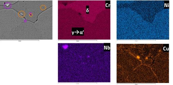
Fig.1 - EDX maps of the main alloying elements of an as-sintered specimen.
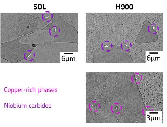
Fig.2 - SEM micrographs of the solution annealed and aged (H900) specimens, with the identification of niobium carbides (purple) and copper-rich phases (pink).
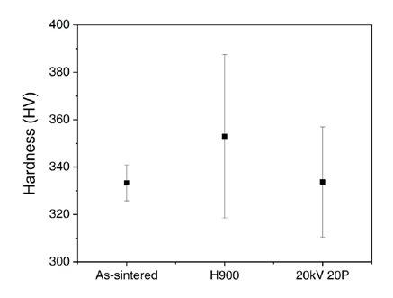
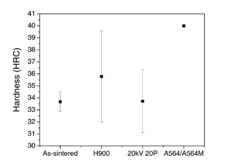
It can be observed in Figure 3 that the H900 treatment was able to produce a slight increase in the average hardness value with respect to the as-sintered condition, which is correlated to the formation of fine coherent copper precipitates after solution annealing, especially in the copper-rich martensite. Nonetheless, the standard deviation of the H900 condition is extremely large and the measured values partially overlap with those obtained for the as-sintered condition. It can be expected that in many cases the indentation was influenced by the presence of porosity and δ ferrite which are softer than martensite, especially after precipitation hardening. One of the surface treated components was analysed as well to determine whether the LEHCEB process would be able to affect the core region of the component: it can be observed that the hardness measured is comparable to that of the as-sintered condition, thus confirming that the surface finishing does not affect the bulk properties of the material.
The Vickers values were converted to Rockwell C hardness values to allow a preliminary comparison with the hardness requested by the ASTM A564/A564M - 19a standard for the H900 aged specimens produced by conventional manufacturing. It can be observed that the treated component does not satisfy the requirement of the standard, at least in terms of average value. Performing macroscopic indentations may produce different results with respect to conversion from Vickers values, althou-
gh it should be considered that the presence of porosity and δ ferrite in that case would still be influential because macroscopic indentations could not avoid these defects. The poor performance of H900 specimens could suggest that nitrogen-assisted cooling in furnace is not as effective as water quenching or air cooling in the whole range of temperature. The employed procedure increases the cooling rate at high temperatures with respect to furnace cooling, but it cannot maintain such rate until room temperature is achieved. Slower rates could favour the occurrence of undesired nucleation and growth of precipitates, and excessive tempering of the martensite, especially after solution annealing at high temperature, with detrimental effects on hardness.
As can be seen from Figure 4, the LEHCEB treatment mitigates the surface inhomogeneity of the as-sintered specimens, which is typically influenced by the particles size and by the layerwise deposition method. The surface average roughness (Ra) is reduced by increasing the voltage of the electron beam from 20 kV to 30 kV, as verified by the measurement performed on the y direction parallel to the wear track on the samples, shown in Figure 5. In addition to the average roughness value decrease, also the standard deviation of the measurements on the surface-treated components is reduced, owing to the complete filling of the surface valleys generated by residual porosity, mostly in correspondence with the interlayer regions. These areas are known to be preferentially affected by the presence of open porosity near the surface, due to the additional macroscopic voids generated by the removal of the organic binder during the preliminary debinding process [9].
The cross sections of the surface treated samples were analysed to determine the thickness of the melted layer by the LEHCEB and to evaluate variations in the type of microstructural features. As can be seen in Figure 6, the accelerating voltage of the electron beam has a great influence on the resulting surface: the treated layer of the 20 kV sample is extremely thin (< 1 μ m) and not as homogeneous as the one of the 30 kV samples, whose thickness reaches about 4 µ m. It can be observed, especially in the 30 kV specimen, that the treated surfaces have a uniform microstructure constituted by martensitic grains, which
are finer than those within the bulk volume that extend for tens of micrometres. It can be noted as well that δ phase regions seem to be completely absent in correspondence with martensitic grains and almost completely removed where this kind of ferrite was reaching the surface in the as-sintered specimen. Therefore, the fusion of the surface material and the subsequent rapid cooling does not allow for the nucleation of ferritic grains, but rather the formation of austenite followed by the martensitic transformation at low temperature.
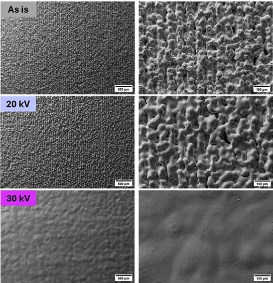
Fig.4 - SEM images of the surface morphology of as-sintered and surface treated (LEHCEB) samples at 20 kV and 30 kV.
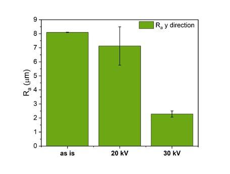
Fig.5 - Mean roughness values measured in the y direction of the samples surface.

Fig.6 - SEM micrographs of the melted surface region highlighted between the light purple lines for 20kV and fuchsia lines for 30 kV.
From Figure 7, it can be observed that all the specimens display the achievement of a stable coefficient of friction (COF) after an initial transition. Nonetheless, the nature and the duration of the low friction region vary according to the selected parameters for the treatment. Indeed, the as-sintered specimen experiences an immediate and continuous transition toward an average COF above 0.9. The H900 aged material progressively stabilizes at a friction coefficient value lower than 0.6, thanks to the hardening effect of copper precipitation in the martensitic grains. The surface treated samples (light purple and fuchsia lines in Figure 7) present two distinguishable regions of the curve connected by a sharp transition: the first with a stable low friction coefficient at about 0.1 and the second with a COF in the 0.4-0.7 range. The stabilization at low friction value is evident for the sample treated at 30 kV, whereas it is interrupted rapidly for that obtained at 20 kV. The characteristic behaviour of the modified surfaces can be explained by the abrupt change of the microstructural and mechanical properties of the material when the complete wear of the molten layer, formed during the electron beam treatment, is achieved. This hypothesis is confirmed by the visible shift of the second region in the sample superficially treated with a beam acceleration of 30 kV compared to the one treated with a lower voltage. In fact, the tempered martensitic layer of the 20 kV pulses is thinner compared to that of the 30 kV, leading to an earlier consumption under equal testing conditions. As the pure martensitic surface layer is consumed and the coupling
with the alumina ball changes to the sub-surface region, the wear resistance is reduced and the friction increases owing to the presence of ferrite and martensite with a different thermal history.
In both cases the friction coefficient in the second region stabilizes at a lower value with respect to the as-sintered sample (black line in Figure 7), although the sub-surface material should not be directly affected by the LEHCPEB treatment. In fact, the friction behaviour seems comparable to that of the H900 sample (red line in Figure 7), whose improved performance is associated with the formation of coherent precipitate in the martensitic matrix. Therefore, the difference between the COF of the as-sintered sample and the second region of the superficially treated samples is hypnotized to be linked to the formation of a heat affected zone (HAZ) in the sub-surface region, which modifies the tribological behaviour of these samples even after the consumption of the molten layer.
The roughness of treated samples, together with the thickness of the quenched layer, plays a critical role in the wear track morphology (Figure 8). The surface treated at 20 kV has a broader and more spread track compared to the one at 30 kV, even if the roughness is higher. The as-sintered specimen track is more distributed due to a higher plastic deformation caused by the lower hardness of the material, even if the roughness is comparable to the one of the superficially treated at 20 kV. Finally, the wear track of the sample treated at 30 kV is minimized owing to the reduced wear rate in correspondence with the low COF region that lasted for more than half of the test duration.
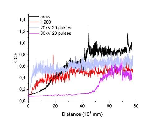
Fig.7 - Coefficient of friction measured for surface treated (light purple and fuchsia), thermally aged (red) and as-sintered (black) samples.

Fig.8 - SEM images of the wear track morphology of samples at the as-sintered state (left), surface treated at 20 (centre) and 30 kV (right).
The analysis of the bulk and surface microstructures, as well as the surface tribological performance, provides several insights into the behaviour of the material under different processing conditions.
The cooling process following sintering preserves δ ferrite and promotes the nucleation and growth of copper precipitates, primarily in the ferritic phase where the solubility of copper is lower. These precipitates preferentially segregate at grain boundaries, where they transform from fine precipitates to copper-rich phases. Solution annealing can eliminate copper precipitates from austenite, allowing for controlled precipitation during aging. However, the H900 treatment does not meet ASTM hardness standards due to porosity and residual ferrite content, which reduce hardness. Niobium carbides persist at grain boundaries, regardless of the thermal treatment, due to their high thermal stability.
Surface treatment using LEHCEB with higher accelerating voltage (30 kV) results in a thicker martensitic layer with a low average roughness, while a lower voltage (20 kV) produces a thinner and less homogeneous layer, characterized by residual open pores. The treated surface exhibited fine martensitic grains, with δ ferrite largely absent, indicating that rapid cooling after surface fusion prevented the nucleation of ferritic grains.
The surface-treated samples demonstrated superior tribological performance, with a lower and more stable coefficient of friction compared to the as-sintered and H900-treated specimens, as long as the surface layer was not completely consumed. In particular, the 30 kV treated sample showed the best performance, with an extended low-friction region due to the thicker martensitic surface layer. The wear resistance of the surface treated samples
improved likely due to the presence of a heat-affected zone beneath the surface, which altered the tribological properties even after the wear of the molten layer. The roughness and the thickness of the treated layer play a critical role in wear behaviour, with the thicker 30 kV layer resulting in minimized wear tracks.
Overall, the findings suggest that the surface can be optimized through careful control of thermal treatments and surface modification processes. However, improvements are needed to meet hardness and wear resistance standards, and further analyses should enlighten the microstructural transformations ongoing during the treatment to identify the strengthening mechanisms along the depth profile.
The authors acknowledge Gabriele Impellizzeri and Tommaso Tirelli of Aidro srl for the technical and operative support. The authors also acknowledge the team involved in the PASO project, of which this study is a part. The project is funded under the "FONDO PER LA CRESCITA SOSTENIBILE – Bando Accordi Innovazione DM 31/12/21 - DD 18/03/22 - Progetto PASO-Produzione Additiva di Strumentari Ortopedici, B49J23000620005, ID. 10188".
[1] L COCCHI, M MARIANI, S GRAZIOSI, R VIGANÒ, N LECIS, Design challenges in leveraging binder jetting technology to innovate the medical instrument field, Proc Des Soc. (2024).
[2] W TILLMANN, NF LOPES DIAS, D STANGIER, C SCHAAK, S HÖGES, Heat treatment of binder jet printed 17–4 PH stainless steel for subsequent deposition of tribo-functional diamond-like carbon coatings, Mater Des. (2022).
[3] M YANG, J YAN, P PENG, PD ENRIQUE, MK KESHAVARZ, M VLASEA, Surface functionalization of binder jetted steels through supersolidus liquid phase sintering and electro-spark deposition, Surf Coatings Technol. (2024).
[4] G YELI, MA AUGER, K WILFORD, GDW SMITH, PAJ BAGOT, MP MOODY, Sequential nucleation of phases in a 17-4PH steel: Microstructural characterisation and mechanical properties, Acta Mater. (2017).
[5] CN HSIAO, CS CHIOU, JR YANG, Aging reactions in a 17-4 PH stainless steel, Mater Chem Phys. (2002).
[6] N LECIS, M MARIANI, R BELTRAMI, L EMANUELLI, R CASATI, M VEDANI, ET AL., Effects of process parameters, debinding and sintering on the microstructure of 316L stainless steel produced by binder jetting, Mater Sci Eng A. (2021).
[7] D HUBER, L VOGEL, A FISCHER, The effects of sintering temperature and hold time on densification, mechanical properties and microstructural characteristics of binder jet 3D printed 17-4 PH stainless steel, Addit Manuf. (2021).
[8] M ZAGO, N LECIS, M MARIANI, I CRISTOFOLINI, Analysis of the causes determining dimensional and geometrical errors in 316L and 17-4PH stainless steel parts fabricated by metal binder jetting, Int J Adv Manuf Technol. (2024).
[9] W TILLMANN, NF LOPES DIAS, D STANGIER, C SCHAAK, S HÖGES, Coatability of diamond-like carbon on 316L stainless steel printed by binder jetting, Addit Manuf. (2021).
A. Acquesta, M. Smet, B. Van Hooreweder, T. Monetta
In questo lavoro è stata studiata, innanzitutto la fattibilità di un trattamento di elettrolucidatura utilizzando una soluzione green, a base di etalina, di componenti in rame prodotti mediante tecnologia additiva tramite Selective Laser Melting (SLM). Successivamente è stata studiata l’influenza di alcuni dei numerosi parametri del processo elettrochimico di elettrolucidatura, come la temperatura e la durata del trattamento. I campioni as-built e quelli elettrolucidati sono stati sottoposti ad una caratterizzazione morfologica, a misure di rugosità, analisi chimiche e ad una caratterizzazione elettrochimica. Il trattamento di elettrolucidatura green eseguito sui campioni ha confermato che, questo può essere considerato un valido processo di finitura superficiale anche per i componenti in rame, ottenuti mediante additive manufacturing, alternativo a quello classico in cui vengono utilizzati acidi nocivi per l’ambiente.
INTRODUZIONE
L’Additive manufacturing (AM) o stampa 3D è un processo capace di produrre manufatti tramite una progressiva aggiunta di strati di materiale. Rispetto alle tecniche tradizionali, questa tecnica permette di realizzare pezzi dalla geometria complessa con una riduzione degli scarti prodotti, lavorando direttamente sulle materie prime riducendone gli sprechi ed eliminando lavorazioni postproduzione di asportazione del materiale [1]. Tuttavia, la qualità superficiale dei manufatti è compromessa a seguito dei fenomeni che si verficano durante il processo di produzione. Sono, quindi, necessari trattamenti superficiali post-produzione per ridurre la rugosità superficiale. Quelli più utilizzati sono i trattamenti superficiali di natura meccanica, come la pallinatura [2], e quelli di natura chimica [3]. Candela et al. [4], hanno studiato l’effetto di diversi trattamenti superficiali, singoli o combinati, ovvero un’abrasione meccanica, un’abrasione chimico-meccanica, una mordenzatura e un’elettrolucidatura, su componenti in rame puro ottenuto mediante tecnologie laser PBF. L'abrasione meccanica ha previsto procedure lunghe, 10 giorni, e l'utilizzo di diversi materiali abrasivi per ottenere una riduzione della rugosità del 90 %. L'abrasione chimicomeccanica è stata eseguita in una soluzione contenente
Annalisa Acquesta, Tullio Monetta
Dipartimento di Ingegneria Chimica, dei Materiali e della Produzione Industriale, Università degli Studi di Napoli Federico II, Napoli
Michel Smet, Brecth Van Hooreweder
Dipartimento di Ingegneria Meccanica, KU Leuven, Belgio
acidi inorganici e alogenuri per 5 giorni, rinnovando la soluzione ogni due ore. La mordenzatura è stata effettuata utilizzando una soluzione a base di acido sulfammidico, perossido di idrogeno, n-butanolo e citrato ammonico. Mentre l’elettrolita usato per l'elettrolucidatura era una miscela di acido fosforico e butanolo. Gli autori hanno riscontrato la presenza di pitting nel caso del trattamento chimico, ed una significativa riduzione di massa dopo i trattamenti chimici ed elettrochimici.
Abdel-Fattah e Loftis [5] hanno studiato l’efficacia di un trattamento di elettrolucidatura in una soluzione costituita da una tipologia dei c.d. Deep Eutectic Solvents (DES), a base di cloruro di colina ed etilenglicole, per componenti ottenuti mediante tecnologie convenzionali in alluminio e rame, confrontando i risultati con quelli ottenuti
effettuando il trattamento nella classica soluzione di acido fosforico. L’utilizzo dell’acido fosforico ha portato alla formazione di pitting per lo sviluppo di ossigeno gassoso. In questo lavoro, è stata studiata la fattibilità di un trattamento di elettrolucidatura, utilizzando una soluzione a basso impatto ambientale a base di Etalina, su componenti in rame ottenuti mediante tecnologia additiva Selectrive Laser Melting (SLM).
I campioni di rame, prodotti tramite tecnologia additiva SLM presso l'Università di Leuven, sono stati mascherati lasciando esposta unl'area di 1 cm2, come riportato nel riquadro rosso della Figura 1.
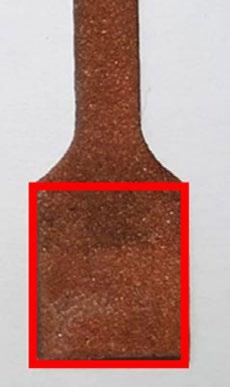
Fig.1 - Area esposta del campione as-built / Exposed area of the as-built sample.
Il trattamento di elettrolucidatura, è stato effettuato in una soluzione elettrolitica green [6], ovvero Etalina, una miscela di glicole etilenico e cloruro di colina in rapporto 2:1. È stata utilizzata una cella elettrochimica a due elettrodi, collegando i campioni in rame all'anodo e una lamina in rame, ottenuta mediante tecnologia convenzionale, al catodo di un potenziostato (Interface 1010, Gamry). La cella è stata adagiata su una piastra riscaldante agitatrice. È noto che i parametri che possono influire sull’efficacia del trattamento di elettrolucidatura sono numerosi. In questo studio è stata studiata l'influenza della temperatura . Sono state effettuate analisi morfologiche e di rugosità,
mediante un microscopio confocale a scansione laser (Lext 5100, Evident Olympus) sui campioni as-built e sui campioni dopo l’elettrolucidatura. In particolare, i parametri di rugosità considerati sono: Sa : media aritmetica della deviazione dalla media; Ssk: simmetria della curva di distribuzione delle profondità; Sku: planarità della curva di distribuzione delle profondità; Sdq: pendenza media quadratica della superficie; Sdr: superficie sviluppata.
Per effettuare i trattamenti di elettrolucidatura è stato necessario individuare innanzitutto il c.d. intervallo di elet-
trolucidatura, in cui si registra una densità di corrente costante, nelle diverse condizioni di test, ovvero variando la temperatura. A tal fine sono state registrate le curve ten-
sione-densità di corrente a 25°C e 70°C, riportate in Figura 2.
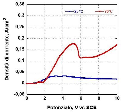
Fig.2 - Curve tensione-densità di corrente registrate in una soluzione a base di Etalina a 25°C (curva blu) e a 70 °C (curva rossa). / Tension-Current density curve recorded in the Ethaline solution at 25°C (blue curve) and at 70 °C (red curve).
Dalle curve è emerso che a temperatura ambiente le correnti registrate sono estremamente basse, ma soprattutto non è facilmente individuabile un intervallo di potenziali di elettrolucidatura. All'aumentare della temperatura, invece, è facilmente riscontrabile il range di elettrolucidatura, compreso fra 6 e 7.5 V. Pertanto, per effettuare il trattamento di elettrolucidatura è stato scelto un valore di potenziale pari a 6V, in condizioni di staticità della soluzione e per una durata di 15 min.
Analisi morfologica
I campioni as-built, come riportato in Figura X, presentano una superficie rugosa, come ampiamente riportato in letteratura, a causa dell’interazione del fascio laser, nelle tecniche DMLS o SLM, con il letto di polvere, che induce la formazione di agglomerati di particelle parzialmente fusi debolmente adese sulla superficie del manufatto in costruzione e altri difetti, quali il balling, il rippling effect, lo stair-step effect [7].
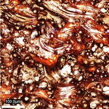
Fig.3 - Immagini ottenute al microscopio confocale del campione non trattato / Optical images of the as-built sample.
Dopo il trattamento di elettrolucidatura, la superficie dei campioni ha mostrato uno smussamento delle asperità, tanto più pronunciato all'aumentare della temperatura.
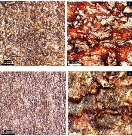
Fig.4 - Immagini ottenute al microscopio confocale dei campioni elettrolucidati in Etalina ad una temperatura di (a) 25°C o (b) 70°C / Confocal images of the electropolished samples in Ethaline at (a) 25°C or (b) 70°C.
Misure di rugosità Di seguito sono mostrati i risultati riguardo le misure di rugosità superficiale. Sono stati, inoltre, riportati i coeffi-
cienti di efficacia di riduzione “RE”, calcolati come la riduzione percentuale dei parametri correlati, in questo caso S a e Sdr
Tab.1 - Parametri di rugosità del campione as-built e dei campioni elettrolucidati. / Roughness parameters of as-built and electropolished samples.
Il campione as-built (non trattato) presenta un parametro di rugosità Sa di circa 18 µ m, uin Ssk pari a 0, indicando un'equa distribuzioni di picchi e valli, un valore di Sku minore di 3, indicando una superficie caratterizzata da picchi poco appuntiti; un Sdq di circa 4 µ m, indicando una superficie non planare ed un valore di Sdr di circa 140, suggerendo una elevata estensione dell'area reale conferita dalla presenza di picchi e valli. Il trattamento di elettrolucidatura green a temperatura di 25 °C ha portato una impercettibile riduzione della rugosità, come evidenziato
in particolar modo dai parametri Sa ed Sdq. Mentre, Il trattamento di elettrolucidatura green a 70 °C, ha comportato una notevole riduzione della rugosità, come dimostrato dai parametri: Sa, pari a circa 10 µ m; Sdq, che ha raggiunto un valore dimezzato rispetto al campione as-built e pari a circa 2 µ m ed Sdr con un valore di circa 52 %.
L’obiettivo di questo lavoro è stato quello di studiare l’efficacia del trattamento di elettrolucidatura in una soluzio-
ne green, a base di Etalina, di campioni in rame ottenuti mediante Selective Laser Melting, al fine di ridurne l'elevata rugosità. Tra i numerosi parametri che possono influire sull'efficacia del trattamento elettrochimico di elettrolucidatura, è stato scelto l'effetto della temperatura. Dalle analisi morfologiche è emerso che i campioni as-built presentano una superficie molto scabrosa, caratterizzata da agglomerati di particelle parzialmente o non fuse adese al substrato, da profonde valli, e ondulazione della parte fusa particolarmente accentuata. Infatti, le misure di rugosità hanno mostrato che il parametro Sa, indice della rugosità media, era di circa 18 µ m e che il parametro Sdr, che riguarda il sovrasviluppo della superficie reale rispet-
to a quella geometrica conferito appunto dalla rugosità, era del 141,4%.
Dalla sperimentazione è emerso che il trattamento di elettrolucidatura green effettuato ad una temperatura di 25°C per una durata di 15 minuti, non comporta una riduzione significativa della rugosità; infatti, i coefficienti di riduzione della rugosità sono risultati essere rispettivamente del 3,3% per la riduzione dell’Sa e 23,4% per la riduzione dell’Sdr. Per quanto riguarda le prove eseguite a 70°C, l’efficacia è risultata maggiore rispetto a quelle eseguite a 25°C, con riduzioni dei parametri di rugosità più elevate. Riguardo il parametro Sa, la riduzione è stata del 46,7%, mentre il parametro Sdr ha visto una riduzione del 63,1%.
[1] F. Calignano, D. Manfredi, E. Ambrosio, S. Biamino, M. Lombardi, E. Atzeni, A. Salmi, P. Minetola, L. Iuliano, P. Fino, Overview on Additive Manufacturing Technologies, Proc. IEEE PP (2017) 1–20. https://doi.org/10.1109/JPROC.2016.2625098.
[2] N.E. Uzan, S. Ramati, R. Shneck, N. Frage, O. Yeheskel, On the effect of shot-peening on fatigue resistance of AlSi10Mg specimens fabricated by additive manufacturing using selective laser melting (AM-SLM), Addit. Manuf. 21 (2018) 458–464. https://doi. org/10.1016/j.addma.2018.03.030
[3] E. Łyczkowska, P. Szymczyk, B. Dybała, E. Chlebus, Chemical polishing of scaffolds made of Ti-6Al-7Nb alloy by additive manufacturing, Arch. Civ. Mech. Eng. 14 (2014) 586–594. https://doi.org/10.1016/j.acme.2014.03.001.
[4] V. Candela, M. Pozzi, E. Chyhyrynets, V. Garcia Diaz, S. Candela, R. Dima, G. Favero, C. Pira, A. Pepato, P. Sonato, Smoothening of the down-skin regions of copper components produced via Laser Powder Bed Fusion technology, Int. J. Adv. Manuf. Technol. 123 (2022) 3205–3221. https://doi.org/10.1007/s00170-022-10408-8.
[5] T.M. Abdel-Fattah, J.D. Loftis, Comparison of the Electrochemical Polishing of Copper and Aluminum in Acid and Acid-free Media, ECS Trans. 25 (2009) 327. https://doi.org/10.1149/1.3203970
[6] A. Acquesta, T. Monetta, S. Franchitti, R. Borrelli, A. Viscusi, A.S. Perna, F. Penta, L. Esposito, L. Carrino, Green electrochemical polishing of EBM Ti6Al4V samples with preliminary fatigue results, Int. J. Adv. Manuf. Technol. 126 (2023) 4269–4282. https://doi. org/10.1007/s00170-023-11400-6.
[7] H. Ali, H. Ghadbeigi, K. Mumtaz, Effect of scanning strategies on residual stress and mechanical properties of Selective Laser Melted Ti6Al4V, Mater. Sci. Eng. A 712 (2018) 175–187. https://doi.org/10.1016/j.msea.2017.11.103
In this work, the feasibility of an electropolishing treatment using a green, ethaline-based solution of copper components produced by additive technology via Selective Laser Melting (SLM) was investigated. Subsequently, the influence of some of the many parameters of the electrochemical electropolishing process, such as temperature and treatment duration, was investigated. The as-built and electropolished samples were subjected to morphological characterisation, roughness measurements, chemical analysis and electrochemical characterisation. The green electropolishing treatment performed on the samples confirmed that this can also be considered as a valid surface finishing process for copper components obtained by additive manufacturing, as an alternative to the classic process where environmentally harmful acids are used.
TORNA ALL'INDICE >


ESTAD will take place for the seventh time after Paris 2014, Düsseldorf 2015, Vienna 2017, Düsseldorf 2019, Stockholm 2021 and Düsseldorf 2023.
ESTAD 2025 will be hosted by AIM, the Italian Association for Metallurgy, in Verona – Italy on 6-9 October 2025.
The knowledge and the development of the new ideas enhance progress. With the 7th European Steel Technology and Application Days 2025 (7th ESTAD 2025) AIM offers attendants and visitors the opportunity to meet, exchange their ideas, perform fruitful discussion and create new professional relationships involving technology providers, suppliers, producers and customers.
The meeting will be focused on the technological advances, changes of the supply chain involving the raw materials and energy sources, transformation of the production processes and plants to accomplish the twin transition (ecological and digital) and the new perspective of steel applications.


Scientific international experts in all fields of iron and steelmaking processes, steel materials and steel application will review the proposed papers.
IRONMAKING
Cokemaking
Sintering and pelletising
Blast furnace ironmaking
Direct reduction and smelting reduction
STEELMAKING
Oxygen steelmaking
Electric steelmaking
Continuous casting, near-net shape casting and ingot casting
ROLLING OF FLAT AND LONG PRODUCTS, FORGING
Rolling of long and flat products
Forging
STEEL MATERIALS AND THEIR APPLICATION, ADDITIVE MANUFACTURING, SURFACE TECHNOLOGIES
HYDROGEN-BASED STEELMAKING, CO2-MITIGATION, TRANSFORMATION / ENVIRONMENT /ENERGY
CO2 mitigation in iron and steelmaking
Environmental and energy aspects in iron and steelmaking
DIGITAL TRANSFORMATION


Ing. Giacomo Mareschi Danieli
Danieli
All paper proposals must be submitted online. Please visit: www.aimnet.it/estad2025 and go to the Call for Papers section. Your abstract can be a maximum of 300 words.
To submit an abstract, please proceed as follows:
1) Write your abstract (max. 300 words)
2) Submit your abstract online at: www.aimnet.it/estad2025/ > Call for Papers section (please completely fill out all fields)
3) Papers must be submitted in English
4) All papers must focus on best practices
The conference language is English.
Please submit your abstracts by 28 February 2025. All abstracts will be refereed by the scientific international experts. In the case of too many submissions, abstracts of equal quality will be accepted on a first come, first serve basis.
Palaexpo Veronafiere
Viale del Lavoro | 37135 Verona VR | Italy
Phone: +39 045 8298151
Verona is easily reachable by plane, train and car. Full information at: https://veronacongressi.it
AIM and all cooperating organizations are committed to adhering strictly to all applicable antitrust laws. Within the context of 7th ESTAD 2025 it is strictly prohibited to discuss competitively sensitive subjects such as pricefixing agreements or agreements on quantities.
The detailed exhibiting and sponsorship packages will be available on the ESTAD website in the following months. In the meantime, companies interested in taking part in the Exhibition or sponsoring the event may contact:

Prof. Christian Bernhard
Montanuniversität Leoben
Prof. Carlo Mapelli
Politecnico di Milano
tel. +39 030 2540006 commerciale@siderweb.com
Via Filippo Turati 8 | 20121 Milano MI | Italy
Email: estad2025@aimnet.it
Phone: +39 02 76021132 www.aimnet.it/estad2025
A. Bongiovanni, A. Castellero
Aluminum has a key role in the automotive industry, thanks to its lightweight, easy recyclability and corresponding achievable low carbon footprint. Its employment will continue to increase, with castings having the heaviest role. High Pressure Die Casting products are usually produced with secondary material but characterized by low mechanical properties, due to the high Fe content and the detrimental β -Al5FeSi phases. HPDC structural components, used in the vehicle BiW, are instead cast with primary aluminum for achieving high ductility and strength. The decarbonization of the automotive industry is requiring new alloys with higher recycled amounts and high mechanical properties. The laboratory casting validation and the upscaling to structural components is an important step during the development of new alloys. This study presents the comparison and characterization of a 70% end-of-life scrap AlSi10MnMg alloy, suitable for structural components, first cast in laboratory and then in industrial facility. Casting quality, assessed through evaluation of defects and microstructure, along with the mechanical properties are compared. The industrial process leads to fewer casting defects (cold flakes and cold joints) and rare α -Al15(Fe,Mn)3Si2 sludge particles. The hardness is affected by the different thickness and the small variation in chemical composition, but in all cases is compliant to with EN 1706 minimum values . The bending test, scarcely sensitive to defects compared to standard tensile test, gives similar ductility results with higher values for the industrial component. The microstructure, hardness and corrosion behavior are comparable to primary alloy’s ones.
KEYWORDS: RECYCLE, ALUMINUM ALLOY, HIGH PRESSURE DIE CASTING, ALSI10MNMG, AUTOMOTIVE, STRUCTURAL
Casting is the leading manufacturing technology for automotive aluminum components, thanks to the complex shaped components with good mechanical properties obtained at relatively low price. It represents around 65% of the total aluminum used in a car produced in Europe in 2022 [1] and a steady 25% increase is foreseen by 2030. The housings for E-drive, battery pack and other electric vehicle specific features are the components that lead this growth. High Pressure Die Casting (HPDC) is the most used casting process, representing approximately 60% of the automotive aluminum casting [2]. HPDC products are traditionally the engine, the transmission housing, the oil pan and other components without high mechani-
Department of Chemistry, NIS, University of Turin, Italy *andrea.bongiovanni@unito.it, alberto.castellero@unito.it
cal requirements. The alloys used are usually secondary, obtained easily from recycling and with great advantages as low price and low carbon footprint. Secondary alloys production emits almost 95% less than the primary production route. These alloys, though, possess iron contents around 1%wt and this poses limitations to their use due to the formation of the β -Al5FeSi phase, characterized by brittle needle shape [3], that greatly limits the elongation at fracture down to 1-2%. High performance components, usually employed in the vehicle Body in White (BiW), require high ductility, because of their need for excellent energy absorption during a possible crash. These structural components are manufactured with primary aluminum alloy, with a strictly limited Fe content and low impurity levels. Ductile alloys are designed for suppressing the detrimental β -phase by alloying other elements such as Mn, Cr and Co. Mn is the preferred Fe-modifier, able to form the polyhedral-shaped α -Al15(Fe,Mn)3Si2 phase [4] and contribute to avoid die soldering too. Most of the industrial structural ductile alloys have a composition close to the AlSi10MnMg alloy defined in the EN 1706 standard [5]. Suppressing the Fe content by only increasing Mn is not a solution for employing secondary alloys in ductile applications, since the alloy would tend to form large intermetallics that hindered the mechanical properties. Recycled aluminum alloys have not been used up to now in HPDC structural components due to the increase of the tramp elements (Fe, Cu, Zn) during the recycling processes. The need of the automotive industry to reduce the carbon footprint of the raw material used in the vehicles, poses more focus on recycled alloys. Much research is ongoing for developing high-recycled content alloys with high mechanical properties with different alloying correcting elements and varying Fe contents. The research is usually done in universities or research centers with characterizations performed on specimens casted in small HPDC machines. This gives reliable data of the material properties, but the real components casted in industrial facilities could have some behavior divergences, due to the different scale of the part dimension and the manufacturing equipment used. The investment cost of an industrial facility prohibits their massive use in the development phase. In this work, a recycled AlSi10MnMg alloy with 70% End-of-Life (EoL) scrap was firstly casted and characteri-
zed in laboratory with a small die, and then a real structural component was produced in industrial environment. The alloy was developed using the EN 1706 – 43500 alloy as reference, the standard name for AlSi10MnMg. The aim is to compare and highlight the differences in the casting quality and the mechanical properties. Casting defects, porosity and microstructure were evaluated, and hardness and bending tests were performed for assessing the strength and ductility of the material. Corrosion validation was performed following automotive standards.
In this work, one of the six AlSi10MnMg HPDC alloys variants developed and characterized at specimen scale was selected for the manufacturing of a structural automotive component at industrial scale. This alloy contains on average 70% of end-of-life scrap and this value optimizes the balance between the sustainability, due to the high-recycled rate, and the low critical raw material added to the remelted aluminum. When recycling a high amount of EoL scrap, the final composition needs to be adjusted to achieve the correct composition. The main elements to be added are usually Si and Mg, with the latter depending on the alloy design: lowering the Mg content leads to higher ductility, and this was the choice for the alloy developed in the present study. Si content instead needed higher raw material: this alloy had 4.3% Si added to achieve the 9-11.5% Si range required by the standard [5]. Nonetheless, the final Si level was close to the lower limit for the second batch produced for the component casting, as shown in Tab. 1. The variant was designed at the upper tolerances of the detrimental elements of the EN AC 1706 - 43500 alloy, with increased Fe and Cu for assessing the limit of a composition close to the standard, but capable of allowing higher recycling rate. These two elements, with low and strict tolerances, are the most problematic when increasing the recycling rate. A 5250-kN locking force Buhler cold chamber HPDC machine equipped with a VDS vacuum unit (V-HPDC), a shot sleeve with an internal diameter of 60 mm and a stroke of 450 mm was used for producing the specimens for the characterization. The die was designed to fabricate a 180x170 mm flat plate piece with 3 mm thickness (Fig.1a) at 100 mbar residual pressure, obtained by a ProVac CV 300 chill vent. The
melt temperature during casting was 720°C, and the mold was heated by oil circulation to approximately 180°C. The structural components were produced in an industrial environment with a 27000-kN vacuum HPDC machine with
8 channels die thermo-cooling units. The whole casting, measuring 420x550 mm and weighing 9 kg, is shown in Fig1b. The wall thicknesses range from 3 to 8 mm according to the area and vary with the draft angle.
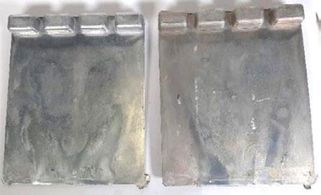
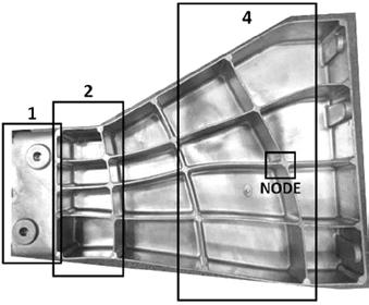
Fig.1 - 180x170x3 mm specimens (A, as cast on the left and after heat treatment on the right) and the structural component (B) analyzed in the four different indicated areas: 1, 2, 4 and node.
The specimens were studied in three temper states: ascast (F), artificial ageing (T5) and solution and artificial ageing (T6). T5 heat treatment involved two hours at 190°C, while the T6 parameters were solution heat treatment at 490°C for one hour, water quenching and artificial ageing at 230°C for one hour. For the structural component, only T5 was performed for avoiding blistering and distortion, typical of the T6 and that could be problematic for a massive HPDC component. Furthermore, T5 heat treatment leads to yield strength increase that is required by the structural application. This choice is also in line with the trend of the automotive sector of avoiding heat treatment or reducing it, for lower CO2 emissions and related costs. For this reason, the demonstrator was characterized in the F condition too. The microstructure of the samples was examined using an optical microscope after etching for 10 seconds with a solution of 0.5 ml HF and 99.5 ml distilled H2O. The cross section of the metallographic samples from the 180x170 specimens was 30x3 mm 2, while the cross sections from the component vary according to the area, ranging from 3 mm to 8 mm thickness. The bending tests were carried out on 50x50 mm samples with test parameters established based on VDA 238-100 standard [6]. A universal tensile machine equipped with a bending device was used for this test. This setup used a 0.2 mm radius. The hardness was measured on the surface of the casted samples for both manufacturing configurations,
using an EMTO-TEST DuraVision G5 Brinell machine. The evaluation of the corrosion behavior was performed following the B368 standard using cataphoresis coated plates. ASTM B368 is also known as CASS test (Copper-Accelerated Acetic Acid-Salt Spray (Fog)) and is a typical test used in automotive. For each temper condition, rectangular shape specimens were cut from the component and coated with the anti-corrosion cataphoresis treatment. A linear scratch was then performed on the protective layer for exposing the aluminum substrate to the corrosion test for 168h. The samples for the micrographic, bending and hardness test were cut out from the center of the 180x170 casted plates. The corrosion specimen’s location in the die has no influence on the corrosion behavior as they were cut out randomly from the plate. Three specimens per type were used in each test. The samples from the component for the micrographic and hardness test were cut out from different areas of the casting, according to the casting quality obtained by the filling and solidification simulation performed. Four different areas were selected, identified as ‘1’, ‘2’, ‘4’ and ‘Node’. The areas are reported in Fig.1b, and ‘Node’ is the cross section of the casting intersections, identified as the last solidified points in the whole casting. Three specimens per type were used in each test. Bending tests were performed only on area ‘2’ and ‘4’ with 5 mm thickness specimens.
During the casting steps of an aluminum alloy, the chemical composition can slightly change. Compared to other manufacturing methods, casting involves remelting and movements of the liquid metal from one mold to the other, until the final die, where it will solidify in the final shape. From the first solidification as ingot, the aluminum alloy is remelted in the casting facility and the liquid metal is treated for removing the hydrogen entrapped by using a rinsing gas and stirring. Hydrogen is a major factor in the casting porosity due to its very low solubility in solid state aluminum [7]. During this operation, fluxes are used for removing the solid impurities, as oxides and other inclusions, via flotation. The clean molten aluminum is then ready for the casting and is transferred to the holding furnace, from which the material is taken in each casting shot. This is the last step before the final injection, where all the liquid aluminum solidifies in a few seconds, according to the part dimension. During the two solidification steps, the material is in contact with the steel die and with the atmosphere, hence the elements can react with the molds or be oxidized, leading to compositional variations. The chemical composition, measured by Optical Emission Spectroscopy, is shown in Tab.1. The composition was measured in different steps for both the pieces studied: on the ingot and on the casted 180x170 plates; on the ingots, after the degassing and after the casting for the demonstrator component. It can be first noted that the overall composition differs from the specimen to the component. The alloy ingots were produced in two separate times and, even if the same amount of EoL scrap was used, the result is different due to variations in the scrap mix. To achieve the exact same chemical composition, more pure master alloys (i.e. Al-Si, Al-Mn) should have been added, resulting in a de-
crease of the total recycled percentage and increase of kg CO2/kg Al. The 1%wt difference of the Si content is the most evident change, but this difference did not lead to castability problems. On the contrary, it could lead to an improved ductility, since eutectic Si particles are brittle and in the absence of defects or more brittle phases, as β -Al5FeSi phases or sludge particles, are responsible for the cracking propagation [4]. The higher Mg content in the component could lead to higher strength especially after T5 heat treatment, associated with the precipitation hardening effect related to the increase in Mg2Si phases [8]. Slightly more Fe is present in the second casting, but in both casting types it is observed an increase of the Fe content from the ingot to the final casting. It is known that during recycling the Fe content increases, but in general all melt activities can potentially increase it [3]. Aluminum and iron have a high affinity, inter-diffusing on contact and forming intermetallics that generate die soldering, a major problem in HPDC for the die life [9]. Most aluminum HPDC alloys contain from 0.8% to 1.1% Fe to prevent die soldering, but for high-performance alloys such a high Fe content is impossible: it would form abundant brittle β -AlFeSi intermetallics, which hinders the ductility. Mn is essential for this reason, as it counteracts the die soldering effect and promotes the formation of blocky or Chinese scriptlike α -Al15(Fe,Mn)3Si2 compounds instead of β phases [3]. There is a limit to the quantity of Fe and Mn in the alloy because of their tendency to solidify and segregate intermetallics before dendrite formation. The defined Sludge Factor (SF) is an empirical parameter that represents this phenomenon, typically occurring in the holding furnace and/or the shot sleeve [10]. The main intermetallic forming is α -Alx(Fe,Mn,Cr)y Si z and the empirical equation (1) by Gobrecht [11] and Jorstad [12] uses the Fe, Mn and Cr content to calculate it: (1)
The higher content of Mn in the specimen composition led to a higher SF, resulting in more sludge α -phase particles as will be shown in the micrographic analysis section. Another effect of the foundry processes is the decrease of the Strontium (Sr) content from the ingot to the final casting. Strontium is essential for structural alloys as it promotes the morphological modification of eutectic Si,
that is naturally acicular and brittle, improving the elongation at fracture and ductility of the alloy. Even an addition in the order of hundreds part per million of Sr, leads to the spheroidization of the coarse plate-like particles to well-refined fibrous phases [13]. The loss of Sr can be due to oxidation or segregation during the melting phase with subsequent removal during the degassing phase [7, 14].
Tab.1 - Chemical compositions measured by Optical Emission Spectroscopy (OES), Sludge Factor (SF) and recycle content (%).
MICROGRAPHIC EXAMINATION
Defects
HPDC components are characterized by fine-grained structure thanks to the rapid cooling of the liquid aluminum in the die cavity. In this technology, defects are the most detrimental features for the mechanical properties, especially porosities. Their impact is greater than microstructure brittle phases, which have a heavier effect on slower solidification casting methods, like low pressure die casting. Despite the vacuum assisted operation, the high turbulence during the filling shot can produce numerous defects: casting (i.e. cold joints and cold flakes), solidification (shrinkage porosity) and air-entrapment (gas porosity) defects. Casting the same material in two different manufacturing environments can result in different presence and distribution of the defects.
Figure 2a-b shows the porosities in the laboratory casted specimens before the heat treatment and after T5, while Fig.2c-d the porosities in the industrial component in area 2 and in the node. It can be noted that the T5 heat
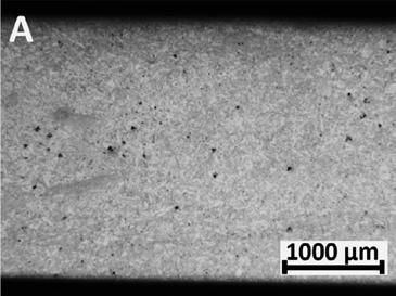
treatment does not enhance the porosities at macroscopic level, as can happen after a T6 heat treatment [15]. Gas entrapment pores are the most frequent in the specimens, characterized by spheroidal shape and in general small and dispersed, with only few big voids as in Fig.2b. Shrinkage macro-porosity is observed in the component in the last solidifying areas and in the thicker sections, as in area 4 and in the nodes (Fig.2d) with sizes up to 1 mm. Gas pores are instead present throughout all the areas of the casting. Laboratory plates macrography in Fig.2a-b have a similar appearance to the industrial component in Fig.2c. What they have in common is the rapid solidification, derived by the low thickness and small melt aluminum volume to be cooled of the plate specimen, and the die of the component which was designed for having faster solidification and resulting better properties in these areas. The material solidifies at last in the thickest areas, as in the nodes, where the cross-section thickness is almost 20 mm. The volume shrinkage of aluminum is not balanced enough and generates macro void, as visible in Fig.2d.
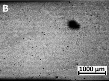
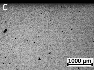
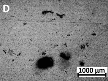
Fig.2 - Optical micrographs showing the porosities in the as-cast (a) and T5 (b) temper, for the laboratory casted specimen, and in the first solidifying areas 1 and 2 (c) and last solidifying area, the nodes (d), for the industrial casting component.
The differences in casting quality peak when observing the other casting defects. Figure 3a shows how, even at low magnification, cold flakes and cold joints are visible in the specimen’s cross section. Cold flakes are formed during the injection of the liquid metal in the die cavity, prior to solidification in the die cavity. As the shot sleeve is filled, a layer of aluminum initially solidifies and oxidizes in the cold chamber. When the plunger injects the molten material into the die, this solidified layer breaks into numerous small particles around the casting [16]. The casting component (Fig.3b) is more homogeneous with
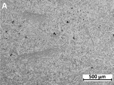
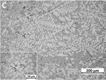
only some primary aluminum dendrites, that are solidified externally to the die and are characterized by a bigger dimension. While the defects from the laboratory casting are continuous and found in all the sample sections analyzed, only few cold flakes and cold shots were observed in the industrial casting. Fig.3c and Fig.3d reports two examples of casting defects, cold flakes, that show similar appearance. The dendritic structure is coarser than the surrounding bulk and both contains sludge intermetallic particles, as better shown in the insets of the figures.
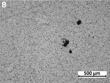
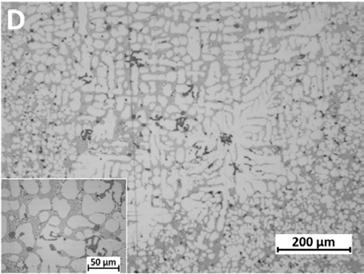
Fig.3 - Microstructure of the cross sections in the specimen (a) and in the component (b), showing the average casting quality observed. Examples of cold flake observed in the specimen (c) and in the component (d).
Other defects often seen in the specimens are cold joints, visible even at low magnification as the darker flat areas in Fig.3a. These occur when, during the die filling, a molten metal flow with a superficial oxide layer encounters another liquid front. The produced interface is a discontinuity in the material that can facilitate the initiation or the propagation of a crack. During T6 heat treatment, the discontinuity is highlighted and the matching fronts can separate, generating a linear void [15].
The deviations in the chemical composition and the casting quality leads to differences in the microstructure and in the phases present. Figure 4 clearly shows the presence of fine and coarse α -Al15(Fe,Mn)3Si2 intermetallic compounds in the specimen (a) and in the component (b). The Chinese script-like coarse white particles are called sludge particles and solidify in the shot sleeve or during the transfer from the cold chamber to the shot sleeve [13]. These are abundant in the specimen’s microstructure,
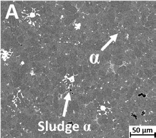
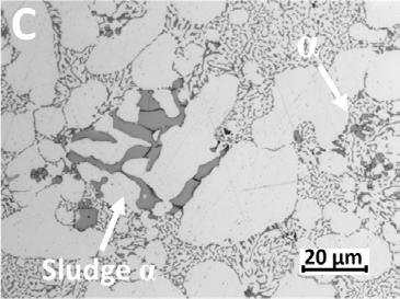
characterized by a higher SF and more casting defects. The industrial component shows fine intermetallics, formed only during the solidification in the die. Their shape is mostly blocky and equiaxial, with a dimension in the order of the µ m, while the sludge particles have a Feret diameter around 40 µ m. Only few coarse α -AlSiMnFe phases were observed in the component, apart from the ones observed in cold flakes as in Fig.3d. These volumes of material solidify outside the die and with lower cooling rates, a combination that helps the formation of the sludge particles. The Mn content in both parts is enough to suppress the undesired β -Al5FeSi phase, characterized by acicular shape and very brittle. Only few of these intermetallics were observed in the thickest areas of the component, but the big porosities shown in Fig.2d represents the main problem. No β -AlFeSi phases were observed in the specimens given the lower constant thickness and the higher Mn content. This is proven by the fact that all the Fe detected in the microstructure is bonded with Mn, as demonstrated by the SEM/EDS analysis maps in Fig. 5.
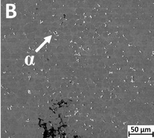
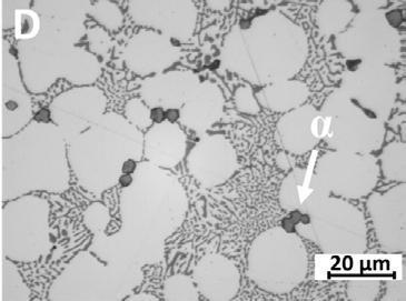
The eutectic silicon particles did not show any relevant modification after the T5 in both castings, unlike the T6 treatment that effectively spheroidized the fibrous morphology, as demonstrated in a previous characterization of the specimens [15]. The effect of the T5 heat treatment can be noted in the Mg2Si particles evolution. Figure 5 shows the EDS maps after T5 for the specimen (a) and the component (b), and it can be noted how the componen-

ts have more Mg concentrated traces, sign of more Mg2Si particles. The minor Mg content shown in Tab.1 of the specimens leads to this difference. No relevant change was observed in the specimens Mg2Si particles after the T5, given the low amount of Mg. An increase in dispersion and dimension of Mg phases was instead visible after the heat treatment for the component.
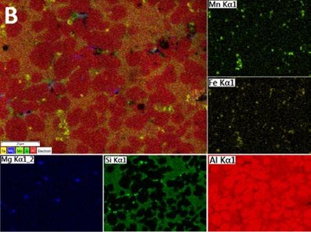
Fig.5 - EDS maps of the microstructure after T5 heat treatment of the specimens (a) and the component (b).
Hardness
Table 2 reports the hardness measured on the surface of both the specimen plates and the structural component, for all the heat treatment conditions. The values reported for the component are the average of all the measurements performed throughout the component areas shown in Fig.1b, since no difference was noted in the surface hardness. Observing the specimen values between the three tempers, it can be appreciated the T6 effect that improves the ductility, thus decreasing the strength and the relative hardness of the material. T5 did not lead to a relevant improvement, with only a 2 HB increase, while the 10-15 HB delta of the component met the expectations. This could be related to the chemical composition of the specimens, which had a Mg content of 0.14%wt., too low for forming enough new Mg2Si precipitates after T5. The hardness enhancement is clear in the component, with 11 HB more than in the as-cast, thanks to the higher Mg content of 0.26%wt. As also shown in Fig.5 by the EDS analysis, very few Mg2Si phases were noted in the specimens while they are more present in the component, with a dimension and
dispersion growth after T5. A relevant difference lies in the as-cast values between the two castings. An explanation of this difference could be the thickness of the two analyzed parts, with the 180x170mm plates being 3 mm thick and the components ranging from 3 to 8 mm. The minor thickness leads to lower solidification and cooling time, resulting in higher mechanical properties. A similar behavior is noted in the skin of the aluminum castings, as reported in a study of Yang [17], which proves how the superficial material in HPDC part has higher hardness than the core. The higher cooling rates of the material in direct contact with the die leads to a finer microstructure and, thus the decreasing thickness enhances the skin-effect on the mechanical properties. A second contributor to this increase in the as-cast state is the higher content of α -Al15(Fe,Mn)3Si2 intermetallics, both in fine and coarse dimension. All the hardness values reported in Tab.2 satisfy the minimum hardness values specified by the EN 1706 standard for the 43500 – AlSi10MnMg alloy, i.e., 65 HB for F temper, 80 HB for T5 and 60 HB for T7 that can be considered a reliable minimum limit for T6 too [5].
Tab.2 - Mechanical properties: Brinell hardness results performed on the surface of the casting and in the cross-section.
The results of the bending test are reported in Table 3 and well correlates with the hardness results. Three point bending test assesses the local ductility of the material, compared to the global ductility measured with tensile test along the entire gauge length of the specimen. This helps to reduce the influence of the casting defects on the elongation at fracture, since only part of the resistant section is under tension and enhances the skin-effect role in improving the mechanical properties. Comparing the results from the specimens and the component, a small improvement in bending angle is noted in the industrial casted material. The better casting quality, observed by the lower casting defects in Fig.3, leads to higher ductility, and in the first solidifying area, i.e. Area 2, this effect is more evident. This deviation can be also caused by the higher content of α -Al15(Fe,Mn)3Si2 sludge intermetallic observed in Fig.4 of the specimens. The high Mn content combined with the relatively high 0.17%wt. Fe leads to high SF and the formation of many sludge particles. As demonstrated by
Bosch et al. [4], when the Mn content is too high and leads to α -AlSiMnFe sludge formation, the multiple cracking of the sludge particles becomes the crack initiation mechanism, reducing the ductility. A similar behavior was observed in the hardness, with an increase in the specimen’s values in the as-cast state. Comparing the standard deviation of the values in as-cast and T5 conditions from the two castings, it can be better appreciated the defect effect on the results. The scattering of the values is constant on the component with a low St.Dev., while the specimens show higher dispersion. However, the averages obtained in the two tempers are comparable and show the same trend after T5. The T6 heat treatment was performed only in the laboratory castings, and the effect of the eutectic Si spheroidization is clear in the improvement of local ductility. Regardless of the typical blistering problem of HPDC parts after T6 [8] and the porosity increase, the St.Dev. decreases drastically. The increment of ductility is enough to have a homogenization effect on the material, with very low standard deviation.
Tab.3 - Mechanical properties: bending angle with standard deviation.
In the automotive industry, structural components of the Body-in-White (BiW), like the one examined in this study, are always treated with anti-corrosion coatings. The cataphoresis process, also known as e-coating, involves electrochemically applying an epoxy-type coating to a metal component. This method is the primary means of protection of BiW parts from corrosion, but it is essential to ensure the compatibility and strong adhesion of the cataphoresis coating to the material. A major concern for high-recycled content aluminum alloys is the copper (Cu) level, which could lead to corrosion and compatibility issues with the cataphoresis coating. During the ASTM B368 test, a standard tape is applied to the preformed scratch and then pulled off to measure the width of the removed material. Specifically, the groove left after removing the tape must be less than 1.5 mm wide. All specimens passed the test, showing similar corrosion behavior with no differences before and after heat treatment and regardless of the manufacturing environment. The studied alloy had a Cu content of 0.02% in the first batch of ingots for the specimens, while 0.15% in the second one for the industrial component. The latter value exceeds the strict limit set by the EN 1706 standard (max 0.03%), but no incompatibility or corrosion issues were observed in the test.
In the present study a recycled AlSi10MnMg aluminum alloy was casted and characterized in two different environments: in a laboratory with a 5250-kN HPDC machine and in an industrial facility with a 27000-kN machine. The alloy was designed for achieving the high mechanical properties required by a structural automotive component. The comparison was performed for assessing the differences in casting quality and properties obtained when developing a new recycled alloy in casted specimens in laboratory and then in a structural component in an industrial facility. The overall casting quality from the two environments shows relevant differences. Even if the laboratory casted part is small and its shape does not include corners and ribs as in the industrial component, the number of casting defects is higher. The natural high productivity and optimized process of an industrial
environment made the difference in the final casting quality. The duration and efficiency of the casting process phases - remelting, material movement and especially the longer duration of the liquid aluminum transfer from the holding furnace to the shot sleeve - made at laboratory level led to most of the defects.
• The chemical composition obtained by recycling a fixed amount of EoL scrap (i.e. 70%) can lead to compositional differences between different batches. The composition of the scrap mix used is not a constant variable.
• Gas-entrapment porosity is a “natural” defect of HPDC, and no difference lies between the two foundry environments. Casting quality defects, such as cold flakes and cold joints, were frequent in the laboratory casting , while almost absent in the industrial component.
• The higher SF and lower casting quality of the laboratory specimens, led to high sludge α -Al15(Fe,Mn)3Si2 intermetallics presence. Only fine compact α -AlFeMnSi phases were observed in the structural component.
• No β -Al5FeSi were observed thanks to the well-balanced Fe/Mn content and the low thickness of both castings. Only few were observed in the core of the component’s nodes.
• Low amounts of Mg2Si phases were found in the specimens even after T5, due to the low amount of Mg (0.14%wt.). Higher distribution and dispersion of strengthening Mg phases were observed in the component, having a Mg content of 0.26%wt.
• The hardness in the as-cast temper is higher for the specimens due to the lower thickness, while after T5 the component hardness is higher due to the major contribution of the Mg2Si phases. The average values obtained in all the heat treatment conditions (as-cast, T5, T6) and for both casting types satisfy the minimum values indicated in the EN 1706 standard.
• Bending test was used for assessing the ductility of the material and resulted in being little sensitive to casting defects, thanks to the skin-effect and the local assessment of the test. The same behavior to T5 and similar values even in the as-cast state were obtained. The standard deviation in the specimen castings is much higher due to the casting defects and sludge particles. The T6 treatment enhanced the ductility enough to overcome the defect effect.
• Corrosion resistance is provided by cataphoresis coating
for automotive structural components and the adhesion compliance must be guaranteed. Even with Cu level exceeding the EN 1706 upper limit, the material studied is compliant to the automotive standards.
The results presented in this work have been partially obtained within the framework of project Horizon 2020 SALEMA, Grant Agreement no. 101003785.
The author would like to thank CRF Centro Ricerche Fiat – Stellantis, partner of the SALEMA project, for the
laboratory support and the permission to publish the results.
The author acknowledges the support from the Project CH4.0 under the MUR program "Dipartimenti di Eccellenza 2023-2027" (CUP: D13C22003520001).
[1] Aluminum content in European Passenger Cars, Public Summary, 2023, Ducker Frontier.
[2] Bonollo, F., Gramegna, N. & Timelli, G. High-Pressure Die-Casting: Contradictions and Challenges. JOM 67, 901–908 (2015).
[3] Taylor, John. (2012). Iron-Containing Intermetallic Phases in Al-Si Based Casting Alloys. Procedia Materials Science. 1. 19–33
[4] Bösch, Dominik & Pogatscher, Stefan & Hummel, Marc & Fragner, Werner & Uggowitzer, Peter & Göken, Mathias & Höppel, H.W. (2014). Secondary Al-Si-Mg High-pressure Die Casting Alloys with Enhanced Ductility. Metall and Mat Trans A. 46.
[5] ISO 1706:2020, “Aluminum and aluminum alloys – Castings – Chemical composition and mechanical properties”, Int. Organ. Stand, 2020.
[6] VDA 238-100 test specification draft: Plate bending test for metallic materials. 12/2010
[7] Podaril, M.; Prášil, T.; Majernik, J.; Kampf, R.; Socha, L.; Gryc, K.; Gráf, M. Aluminum Melt Degassing Process Evaluation Depending on the Design and the Degree of the FDU Unit Graphite Rotor Wear. Materials 2022, 15, 4924
[8] J.Y. Zhang, E. Cinkilic, X.J. Huang, G.G. Wang, Y.C. Liu, J.P. Weiler, A.A. Luo, Optimization of T5 heat treatment in high pressure die casting of Al–Si–Mg–Mn alloys by using an improved Kampmann-Wagner numerical (KWN) model, Mater. Sci. Eng. A, 865 (2023) 144604
[9] Kohlhepp, M.; Uggowitzer, P.J.; Hummel, M.; Höppel, H.W. Formation of Die Soldering and the Influence of Alloying Elements on the Intermetallic Interface. Materials 2021, 14, 1580.
[10] Ceschini, Lorella & Morri, Alessandro & Toschi, Stefania & Bjurenstedt, Anton & Seifeddine, Salem. (2018). Influence of Sludge Particles on the Fatigue Behavior of Al-Si-Cu Secondary Aluminium Casting Alloys. Metals. 8. 268
[11] Gobrecht, J. Settling-out of Fe, Mn and Cr in Al-Si casting alloys. Giesserei 1975, 62, 263–266. 15.
[12] Jorstad, J. Understanding sludge. Die Cast. Eng. 1986, 30, 30–36
[13] Dahle A.K., K. Nogita, S.D. McDonald, C. Dinnis, L. Lu, Eutectic modification and microstructure development in Al–Si Alloys, Mater. Sci. Eng.: A 413–414 (2005) 243–248.
[14] Ganesh, M R & Reghunath, Nikhil & J.Levin, M. & Prasad, Adarsh & Doondi, Sanapala & Shankar, Karthik. (2021). Strontium in Al–Si–Mg Alloy: A Review. Metals and Materials International.
[15] Bongiovanni, A.; Da Silva, M.; Castellero, A. Comparison of As Cast and T6 heat treatment on high end-of-life-scrap secondary aluminium alloy for High-Pressure Die Casting automotive structural components. La Metallurgia Italiana, 2024, 115(4):50-56.
[16] Ahamed, Aziz & Kato, Hiroshi. (2008). Effect of cold flakes on mechanical properties of aluminium alloy die casts. International Journal of Cast Metals Research - INT J CAST METALS RES. 21. 162-167.
[17] Yang, K.V., Nagasekhar, A.V., Lumley, R., Caceres, C.H.: The skin effect of high pressure die casting Al alloys. Proceedings of the 12th International Conference on Aluminum Alloys, pp. 687–692 (2010).



L’intelligenza artificiale sta trasformando rapidamente ogni aspetto della nostra vita, sia privata che professionale. Questa rivoluzione tecnologica rappresenta una straordinaria opportunità per le nostre aziende, ma richiede anche la capacità di comprendere e anticipare i cambiamenti.
Per questo motivo, AIM ha deciso di lanciare un Centro Studi dedicato all’Intelligenza Artificiale, con l’obiettivo di esplorare le questioni più rilevanti per il futuro del nostro settore.
La guida di questo nuovo Centro Studi è stata affidata alla
Vice Presidente AIM, Raffaella Poggio, considerando la sua esperienza nel campo della consulenza aziendale e della comunicazione, che la rendono una figura chiave per avviare iniziative innovative per le aziende.
Il Centro Studi sarà un Osservatorio innovativo e dinamico e sarà a disposizione dei nostri associati per fornire approfondimenti e insights per supportare lo sviluppo delle aziende associate e non.
Al fine di delineare al meglio le priorità da affrontare, è stato predisposto un breve sondaggio.
Giornata di Studio INNOVAZIONE E DIGITALIZZAZIONE IN PRESSOCOLATA: VERSO IL FUTURO DELLA PRODUZIONE
Kilometro Rosso - Stezzano BG5 novembre 2024
>> SCOPRI DI PIÙ
Giornata di Studio MICROSCOPIA ELETTRONICA APPLICATA ALLA FAILURE ANALYSIS
Campogalliano MO c/o Tec Eurolab7 novembre 2024
>> SCOPRI DI PIÙ
Giornata di Studio FUTURO SOSTENIBILE E COMPETITIVO DELLA METALLURGIA DELLE POLVERI TRADIZIONALE
Maerne VE c/o Pometon - 14 novembre 2024
>> SCOPRI DI PIÙ
Corso PROVE NON DISTRUTTIVE
Milano c/o Fast - 21-22 novembre 2024
>> SCOPRI DI PIÙ
L’elenco completo delle iniziative è disponibile sul sito: www.aimnet.it
(*) In caso non sia possibile svolgere la manifestazione in presenza, la stessa verrà erogata a distanza in modalità webinar

Giornata di Studio TRATTAMENTI TERMICI E FORMAZIONE METALLURGICA
Ivrea c/o Confindustria Canavese27 novembre 2024
>> SCOPRI DI PIÙ
Giornata di Studio TECNICHE ANALITICHE DERIVATE DAI RAGGI X
Milano c/o Fast - 28 novembre 2024
>> SCOPRI DI PIÙ
International Meeting on CIRCULAR METALLURGY - Raw Materials, By-products & Recycling
Bergamo, 28-29 novembre 2024
>> SCOPRI DI PIÙ
www.aimnet.it
Norme pubblicate e progetti in inchiesta (aggiornamento al 30 settembre 2024)
Norme UNSIDER pubblicate da UNI nel mese di settembre 2024
UNI EN ISO 643:2024
Acciai - Determinazione micrografica della grossezza apparente del grano
UNI EN ISO 10714:2024
Acciaio e ghisa - Determinazione del fosforo - Metodo spettrofotometrico al fosfovanadomolibdato
UNI EN ISO 642:2024
Acciaio - Prova di temprabilità mediante tempra ad un'estremità (Prova Jominy)
UNI EN 12560-1:2024
Flange e loro giunzioni - Dimensioni delle guarnizioni per flange con designazione di classe - Parte 1: Guarnizioni piatte non metalliche con o senza inserti.
UNI EN 1514-1:2024
Flange e loro giunzioni - Dimensioni delle guarnizioni per flange designate mediante PN - Guarnizioni piatte non metalliche con o senza inserti.
UNI EN 10249-2:2024
Palancole di acciaio formate a freddoParte 2: Tolleranze sulle dimensioni e sulla forma
UNI EN 10248-2:2024
Palancole di acciaio laminate a caldo - Parte 2: Tolleranze dimensionali e di forma
UNI EN 13480-1:2024
Tubazioni industriali metalliche - Parte 1:
Generalità
UNI EN 13480-2:2024
Tubazioni industriali metalliche - Parte 2: Materiali
UNI EN 13480-3:2024
Tubazioni industriali metalliche - Parte 3: Progettazione e calcolo
UNI EN 13480-4:2024
Tubazioni industriali metalliche - Parte 4: Fabbricazione e installazione
UNI EN 13480-5:2024
Tubazioni industriali metalliche - Parte 5: Collaudo e prove
UNI EN 13480-6:2024
Tubazioni industriali metalliche - Parte 6: Requisiti addizionali per tubazioni interrate
UNI EN 13480-8:2024
Tubazioni industriali metalliche - Parte 8: Requisiti addizionali per tubazioni di alluminio e leghe di alluminio
Norme UNSIDER ritirate con sostituzione da UNI nel mese di settembre 2024
UNI EN 13480-5:2022
Tubazioni industriali metalliche - Parte 5: Collaudo e prove
UNI EN ISO 642:2003
Acciaio - Prova di temprabilità mediante tempra ad un'estremità (Prova Jominy)
UNI EN 12560-1:2003
Flange e loro giunzioni - Guarnizioni per flange designate mediante classe - Guarnizioni piatte non metalliche con o senza inserti
UNI EN 1514-1:1998
Flange e loro giunzioni - Dimensioni delle guarnizioni per flange designate mediante PN - Guarnizioni piatte non metalliche con o senza inserti
UNI EN 13480-3:2023
Tubazioni industriali metalliche - Parte 3: Progettazione e calcolo
UNI EN 13480-2:2022
Tubazioni industriali metalliche - Parte 2: Materiali
UNI EN ISO 643:2020
Acciai - Determinazione micrografica della grossezza apparente del grano
UNI EN 13480-1:2019
Tubazioni industriali metalliche - Parte 1: Generalità
UNI EN 13480-6:2019
Tubazioni industriali metalliche - Parte 6: Requisiti addizionali per tubazioni interrate
UNI EN 13480-4:2024
Tubazioni industriali metalliche - Parte 4: Fabbricazione e installazione
UNI EN 13480-8:2017
Tubazioni industriali metalliche - Parte 8: Requisiti addizionali per tubazioni di alluminio e leghe di alluminio
UNI EN 10248-2:1997
Palancole laminate a caldo di acciai non legati. Tolleranze dimensionali e di forma
UNI EN ISO 10714:2003
Acciaio e ghisa - Determinazione del fosforo - Metodo spettrofotometrico al fosfovanadomolibdato
UNI EN 10249-2:1997
Palancole profilate a freddo di acciai non legati. Tolleranze dimensionali e di forma.
Norme UNSIDER pubblicate da CEN e ISO nel mese di settembre 2024
EN ISO 23936-4:2024
Oil and gas industries including lower carbon energy - Nonmetallic materials in contact with media related to oil and gas production Part 4: Fiber-reinforced composite materials (ISO 23936-4:2024)
EN ISO 10427-1:2024
Oil and gas industries including lower carbon energy - Equipment for well cementing - Part 1: Casing bow-spring centralizers (ISO 10427-1:2024)
EN ISO 29001:2020/A1:2024
Petroleum, petrochemical and natural gas industries - Sector-specific quality management systems - Requirements for product and service supply organizations - Amendment 1: Climate action changes (ISO 29001:2020/Amd 1:2024)
EN ISO 643:2024
Steels - Micrographic determination of the apparent grain size (ISO 643:2024)
EN ISO 642:2024
Steel - Hardenability test by end quenching (Jominy test) (ISO 642:2024)
EN ISO 9658:2024
Steel - Determination of aluminium content - Flame atomic absorption spectrometric method (ISO 9658:2024)
EN 10088-2:2024
Stainless steels - Part 2: Technical delivery conditions for sheet/plate and strip of corrosion resistant steels for general purposes
ISO 23936-4:2024
Oil and gas industries including lower carbon energy — Non-metallic materials in contact with media related to oil and gas production — Part 4: Fiber-reinforced composite materials
ISO 17650:2024
Low-alloyed steel — Determination of Mn, P, Cr, Ni, Mo, Co, Cu, V, Ti, As and Sn — Inductively coupled plasma optical emission spectrometric method
ISO 10426-5:2024
Oil and gas industries including lower carbon energy — Cements and materials for well cementing — Part 5: Determination of shrinkage and expansion of well cement formulations
ISO 9658:2024
Steel — Determination of aluminum content — Flame atomic absorption spectrometric method
ISO/TR 7035-2:2024
Design and asset management of DIP for water application — Part 2: Design, installation and operation
Progetti UNSIDER messi allo studio dal CEN (Stage 10.99) – ottobre 2024
prEN ISO 17078-1 rev
Petroleum and natural gas industries” Drilling and production equipment ” Part 1: Side-pocket mandrels
prEN ISO 16530
Petroleum and natural gas industries ” Well integrity ” Life cycle governance
Progetti UNSIDER in inchiesta prEN e ISO/DIS – ottobre 2024
prEN – progetti di norma europei
EN 14917:2021/prA1
Metal bellows expansion joints for pressure applications
ISO/DIS – progetti di norma internazionali
ISO/DIS 24203
Oil and gas industries including lower carbon energy — Bulk material for offshore projects — Standard schedule for architectural doors
ISO/DIS 21809-4
Oil and gas industries including lower carbon energy — External coatings for buried or submerged pipelines used in pipeline transportation systems — Part 4: Polyethylene coatings (2-layer PE)
ISO/DIS 14811
Ultra-low carbon high boron steel wire rod for copper cladded wire
ISO/DIS 14313
Oil and gas industries including lower carbon energy — Pipeline transportation systems — Pipeline valves
Progetti UNSIDER al voto FprEN e ISO/FDIS – ottobre 2024
FprEN – progetti di norma europei
FprEN ISO 13503-2
Oil and gas industries including lower carbon energy - Completion fluids and materials - Part 2: Measurement of properties of proppants used in hydraulic fracturing and gravel-packing operations (ISO/FDIS 13503-2:2024)
FprEN ISO 4937
Steel and iron - Determination of chromium content - Potentiometric or visual titration method (ISO/FDIS 4937:2024)
ISO/FDIS – progetti di norma internazionali
ISO/FDIS 13503-2
Oil and gas industries including lower carbon energy — Completion fluids and materials — Part 2: Measurement of properties of proppants used in hydraulic fracturing and gravel-packing operations
ISO/FDIS 8353
Steel sheet, zinc-aluminium-magnesium alloy-coated by the continuous hot-dip process, of commercial, drawing and structural qualities
ISO/FDIS 6934-2
Steel for the prestressing of concrete — Part 2: Cold-drawn wire
ISO/FDIS 4937
Steel and iron — Determination of chromium content — Potentiometric or visual titration method


Organizzate da
con il patrocinio di

Sponsorizzate da


AIM, APCE, AMPP e Università Politecnica delle Marche vi invitano al più importante evento nazionale dedicato alla corrosione e protezione dei metalli!
La XVI edizione delle Giornate Nazionali sulla Corrosione e Protezione si terrà in presenza ad Ancona nei giorni 25, 26 e 27 giugno 2025, presso la Facoltà di Ingegneria dell’Università Politecnica delle Marche.
Le Giornate rappresentano l’evento di riferimento a livello nazionale per la discussione e il confronto sulle questioni scientifiche, tecnologiche e produttive, nell’ambito della corrosione e protezione dei materiali. In particolare, il Convegno prevede la presentazione dei risultati raggiunti da vari gruppi di studio e da numerose aziende del settore, in forma orale e poster.
Presentazione di memorie
Gli interessati a presentare memorie scientifiche e tecniche dovranno inviare titolo, nomi degli autori con relative affiliazioni ed un breve riassunto alla Segreteria organizzativa, entro il 13 dicembre 2024
Le memorie potranno essere proposte: · compilando il form online dedicato all’evento, sul sito www.aimnet.it
inviando i dati richiesti all’indirizzo info@aimnet.it

Segreteria organizzativa
Via Filippo Turati 8 · 20121 Milano tel: +39 0276397770 · +39 0276021132 info@aimnet.it www.aimnet.it