


Hampden, Massachusetts, is located in the Connecticut River Basin, which has experienced more than a doubling of heavy rainfall events over the last sixty years with flood events rising with increases in precipitation. These flooding events have direct impacts on lives and infrastructure as well as indirect impacts on wildlife habitat due to increased inputs of sedimentation and water pollution. Major floods, including those in 1938, 1955, and 2005, have had major impacts on the town. Hampden’s 2015 Hazard Mitigation Plan and 2021 Municipal Vulnerability Preparedness (MVP) Program present observed and projected increases in precipitation and storm events and associated flooding as major concerns.
In these plans, the Town identifies Main Street as the top priority concern: it is a main transportation corridor serving as a commuter travel and emergency evacuation route and connects part of the town to major municipal facilities and emergency services. The Main Street bridge near the confluence of East Brook and the Scantic River is an undersized bridge that floods during heavy storm events and under the MVP action grant is being redesigned. Additionally, the town has gray stormwater infrastructure that is also being overwhelmed during large storm events. Coinciding with the bridge design project is the conceptual design of nature-based green infrastructure solutions throughout the East Brook watershed to address flooding and water quality issues related to climate change and roadway runoff.
The 2022-2023 MVP Action Grant project included an infrastructure assessment process to identify potential sites for interventions in the East Brook watershed. The plan assessed 35 culvert locations susceptible to flooding and damage which were further refined down to three priority project sites for culvert replacement and green infrastructure design interventions, which are the focus of this document. The matrix used to prioritize the sites was based on the location of the culverts at major transportation sites, as well as the opportunity for intervention within the municipal right-of-way (ROW), hence being accessible for construction purposes and highly visible, as a demonstration site for nature-based solutions.
In addition to the Town, core team partners include the Town Conservation Commission; engineering firm Howard Stein Hudson (HSH), which is conducting the bridge redesign; project consultant MLM Enterprises; Mass Audubon, which owns Laughing Brook Wildlife Sanctuary at site A and is collaborating to allow use of space on-site adjacent to the ROW for road stormwater treatment; and the private landowner abutter at site C who also may allow interventions beyond the ROW onto their property.


A:
Goals: Conceptual designs for green infrastructure within and adjacent to the ROW and potential restoration of Smiling Pond to a wetland to increase flood storage capacity.


Historically, urban and suburban communities have used gray stormwater infrastructure—including gutters, storm drains, pipes and culverts—to move and drain water away from buildings and roads. These systems typically convey runoff either to treatment plants or directly into local water bodies untreated. This water runoff can collect and move with it multiple forms of pollution, including road salt, metals, hydrocarbons, fertilizers, excess sediment and nutrients, which can have a negative effect on local water quality. In addition, in many areas, the gray infrastructure is aging and undersized to manage the increasing volumes of stormwater and associated flooding due to climate change.
According to the Water Infrastructure Improvement Act passed in Congress in 2019, Green Infrastructure is defined as "the range of measures that use plant or soil systems, permeable pavement or other permeable surfaces or substrates, stormwater harvest and reuse, or landscaping to store, infiltrate, or evapotranspirate stormwater and reduce flows to sewer systems or to surface waters."
In its Stormwater Handbook, the Massachusetts Department of Environmental Protection (MassDEP) has developed standards for best management practices (BMPs) of green stormwater infrastructure. These standards include a list of necessary site analyses and conditions for designing these systems:
Function (treatment, conveyance, infiltration, etc.)
Soil Type & Permeability
Drainage Area/Contributing Watershed
Depth to Water Table
Depth to Bedrock
Slopes
Thermal Enhancement
Potential Pollutant Load
Proximity to Critical Habitat
Proximity to Water Supplies & Water Bodies
Nearby Buildings & Utilities
Public Acceptance & Cooperation
This document presents these analyses for each of the project sites in order to determine the suitability and design of green infrastructure.


All project sites sit within the East Brook Watershed, and conditions at these sites are influenced by patterns and conditions occurring at the watershed scale. The East Brook Watershed, which spans portions of three Massachusetts towns—Hampden, Wilbraham, and Monson—sits within the Scantic River Watershed, and is part of the much larger Connecticut River Basin.
East Brook originates at the north edge of the watershed at East Brook Pond, and has multiple unnamed tributaries that join it as it flows south. Site A is located near the lowest point in the watershed; East Brook joins the Scantic River just south of the site. Sites B and C are located upstream. Sites A and B are situated along East Brook. Site C sits on an unnamed tributary of the brook. There are two small ponds upstream along this tributary. Otherwise, there are no dams along East Brook but multiple roads with undersized culverts and bridges can function like dams by constricting water flows during flood events.
The East Brook watershed area is 3.7 square miles (2,360 acres). It is less developed than the rest of Hampden. Land use development in the watershed consists mostly of small farms and rural residential properties. 74% of the watershed is forested. Clearing of this land for development, such as housing or solar fields, can have a negative effect on water infiltration, increasing storm flows and potential sedimentation. Currently, a new 80-acre solar field development is being proposed on forested land. Land use and vegetation management along East Brook and its tributaries is particularly impactful. Existing examples occurring within the watershed include channelization of streams, which increases water flow velocity and intensity, and clearing of vegetation along stream banks, which can lead to erosion, and water quality and velocity issues. Impervious cover is low (5%) but many roadways have storm drain systems that pipe runoff directly into streams untreated.

The East Brook watershed contains multiple waterways and wetlands, covering 14% of the watershed, including East Brook which is designated Coldwater Fish Resource (CFR) by MA Division of Fisheries and Wildlife (MADFW). 32% (763 acres) of the watershed is NHESP priority habitat. Some types of green infrastructure, e.g. constructed wetlands, can raise water temperatures, making them unsuitable for use near CFRs.
An important yet controversial species that is present in the watershed is beaver. Some residents and town officials are concerned that they may cause flooding. On the other hand, beavers are a keystone species and have great ecological benefits. As natural landscape engineers, beavers create ponds and wetlands, which aid in groundwater recharge and flood mitigation by slowing water down as it moves through the watershed. They should be viewed as allies in flood mitigation throughout the watershed.
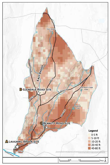
The watershed lies atop granite bedrock of varying depths. This pattern of bedrock depth can have an effect on seasonal stream baseflow as groundwater flows through the ground from hillslopes into streams and rainfall infiltrates and drains through the soil. The depth to bedrock is also an important factor to consider when planning green infrastructure systems as shallow bedrock (less than 3 feet) can limit the excavated depth of these systems, reduce the potential for subsurface infiltration, and reduce the depth over which treatment can occur. Site A sits in an area with bedrock 10 to 40 feet deep, while sites B and C are located in areas with bedrock shallower, at 5 to 10 feet deep. While all three sites thus exceed the minimum depth required, further testing at the site level may be necessary as onsite drainage conditions are also affected by other factors, including the bedrock depth in the surrounding area, soil types, and proximity to seasonal high water table.

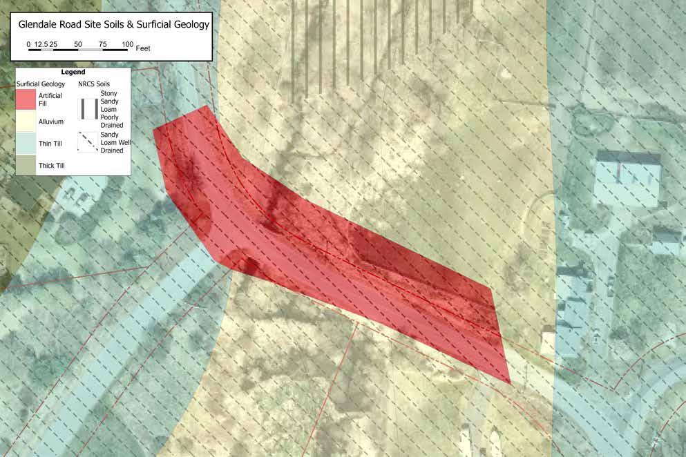
As glaciers receded they created different surficial geological deposits in the landscape, affecting how water flows over and through the land. The hills of the watershed are covered in a combination of thick and thin glacial till, while the valleys have coarse glacial stratified deposits. In addition, as water from melting glaciers formed this landscape, it further left beyond alluvial deposits, a good parent material for rich soils. These ancient geological flows created by water movement (glaciers and rivers) continue to affect how water flows through the watershed today and are an important factor that may affect site conditions for green infrastructure. While generally located within bands of alluvium, which tends to be well draining, all three sites are actually within or adjacent to artificial fill (being situated along built roads and stream crossing) and thus may have unpredictable drainage conditions.

The soils throughout the watershed are for the most part a mix of sandy loam and loamy sand. A few areas of mucky sand exist in some wetland areas. While the majority of the watershed, approximately 80%, is delineated by well draining soil types, there are still many areas with poorly draining soil, including along and adjacent to the waterways spread throughout the watershed. As all three project sites are located in these areas, further analysis will be necessary to determine how this varying pattern of soil drainage expresses itself at the site scale since soil drainage is a crucial factor in designing green infrastructure.

Close to 50% of the watershed is characterized by steep slopes. A large portion of East Brook and its tributaries flow in the narrow valley channels between these slopes. Steep slopes and narrow waterways can lead to increased velocity of water flows during large storm events. While the project sites themselves sit in flatter valley locations, they are affected by the roads approaching them that come down off of the surrounding steep slopes and the runoff flows these roads channel. This can be especially challenging when planning the sizing of green infrastructure stormwater management and treatment systems, especially with increasing large storm events due to climate change. The large volume of fast flowing runoff may require very large systems which may not be feasible within the site limitations.
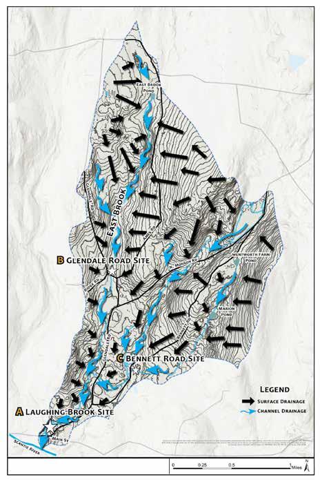
East Brook and its tributaries collect the water that drains off the hills of the watershed. Headwaters for this drainage flow include East Brook Pond at the north edge of Ames Road, a wetland area at the northeast end of North Monson Road and a couple of ponds east of Bennett road. All three project sites sit near or in floodplains where steep slopes meet wider valleys; however, infrastructure like roads, bridges, and culverts at these locations form choke points, constricting water flow where it would otherwise spread out as the valley widens. Site A, Laughing Brook, sits at the mouth of the watershed, and thus has drainage flows coming into it both from the immediate surroundings as well as from the entire watershed, potentially making it more susceptible to flooding.

East Brook and sections of its tributaries are subject to flooding. All three project sites sit partially or completely within the FEMA 100-year flood zone. Although the watershed is heavily forested, and forest cover can slow water flows, the steep slopes of the upper watershed can cause fast flowing runoff, leading to water levels rising quickly and flash flooding patterns. Adding to this issue is the fact that due to climate change, there is an increasing occurrence of heavy precipitation storm events, which may lead to even more flooding, both at the project sites and throughout the watershed.
The issues of flooding and impaired water quality in the East Brook watershed will require a watershed-scale approach. Due to the location of the sites within the watershed, and the limited space available in the rights-of-way for largevolume water detention, it is possible that the efforts of any solutions offered at each site will not have a major impact on flood mitigation at the watershed scale. Efforts need to be made widespread throughout the watershed to slow and minimize runoff. This will require action by and cooperation between the towns the watershed sits in and amongst the residents of the watershed to take action on their own private properties.
Increasing groundwater infiltration and recharge
Maximizing naturally vegetated areas, especially in riparian zones
Reducing of impervious areas
Disconnecting roof runoff from direct discharge to the drainage system and infiltrating directly to groundwater
Applying green infrastructure techniques at the residential scale (rain gardens, green roofs, porous pavement etc.)


“Locally organized, non-regulatory watershed councils have proven to be a powerful method of engaging citizens from all interest groups in planning and implementing solutions to improve water quality and fish and wildlife habitat.“
Rebecca Flitcroft, USDA

Occupying 353 acres of mostly forested land in the East Brook, Big Brook, and Scantic River watersheds, Mass Audubon’s Laughing Brook Wildlife Sanctuary is one of the largest conserved open spaces in Hampden. The project site is located in the area of the sanctuary bounded by East Brook, Main Street and Glendale Road. Visitors to the sanctuary park in a gravel lot where they have access to a grassy field with picnic tables, a small pond for viewing wildlife (officially known as Smiling Pond, a reference to the work of Thornton Burgess, the children's book author who owned the land prior to Mass Audubon), and four miles of unpaved trails.
A berm along the Sanctuary's southern end physically buffers the main gathering area from road traffic, but provides minimal buffering of sight and sound from the busy intersection. The ridge of the berm visually delineates the boundary of the right-of-way (ROW) along Main Street and Glendale Road.
Most of the Sanctuary is within NHESP Priority Habitat for rare species and thus alterations are subject to regulatory review. East Brook, which flows through the Sanctuary and is the catchment for all water on site, is listed by MADFW as a cold-water fishery, as is the Scantic River, which East Brook drains into immediately south of the project site. The site sits within a wellhead protection area, and the 100-year FEMA flood zone.


Land cover on site is mostly vegetation, with some crushed gravel forming a driveway, parking lot, and pathways into the park. Vegetation throughout the area immediately surrounding the parking lot is a mix of mown grass; sporadic ornamental shrubbery, dense thickets dominated by invasive species like Japanese barberry (B. thunbergii), autumn olive (E. umbellata), winged euonymus (E. alata), and multiflora rose (R. multiflora), among others; and a mixed-deciduous tree canopy composed of oak, maple, ash, white pine, and others (C). Within the ROW this vegetation is limited to a grass-covered berm.
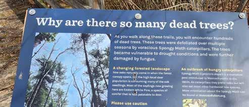
Spongy moth is present in the wooded areas and has resulted in many dead standing trees throughout the sanctuary (A). Other than the gravel driveway and parking lot, a couple of small pavilions near the pond and a walking bridge over East Brook are the only definitively impervious surfaces, although the mown lawn is likely compacted, limiting permeability (D).
Typical land use includes vehicles using the parking lot and entry driveway, and pedestrian activity on the trails, pavilions, and the mown lawn. At the entrance, access in and out of the park is made difficult by a narrow gateway, from which there is poor visibility of fast-moving traffic on Glendale Road and Main Street (B). There is also a sharp turn immediately following entry into the driveway.
Pedestrian use of the sanctuary's amenities is a combination of casual recreation, and formally organized recreational and educational programming offered by Mass Audubon.


The central area of the project site within the sanctuary is a flood plain, and as such, is relatively flat. Exceptions include the berm along the road, the driveway at Main Street, a vegetated mound separating the parking area from the pond, and a berm which forms the southern edge of the pond. Beyond this central area, the park is bounded by steep slopes.
Water flows from East Brook into Smiling Pond via a shallow inlet. As of May 2024, a fallen tree in East Brook is working as a sluice, directing increased flows into the pond (A), which has led to channelization of the inlet and sediment deposition within the pond (B). According to Tom Lautzenheiser, Mass Audubon's Senior Conservation Ecologist, the inlet used to be narrow enough to step over. It is now several feet wide. The pond outlets into the brook via a small concrete weir (C), built when the pond was constructed over an existing wetland in the 1970's. A "beaver deceiver" drain helps maintain pond levels.
Some surface runoff drains directly into East Brook, and some enters two catch basins on either side of the gravel driveway. These basins drain directly into East Brook, just north of the Main Street bridge. According to Mark Langone, Highway Superintendent for Hampden, these basins have been clogged in the past from leaf litter, causing on-site flooding. The total catchment area for these basins is approximately 4 acres.
East of the site, steeply sloped hillsides drain onto Glendale Road and Scantic Road, which in turn slope towards the intersection with Main Street. Existing underground storm drains and pipes collecting water from these roads converge under the intersection before connecting to a catch basin adjacent to the sanctuary. From here the runoff is piped to East Brook, where it outlets just


north of the Main Street bridge. The total catchment area for this storm drain network is 11 acres (see inset map), with approximately 2 acres of impervious surfaces. 1 inch of rainfall adds 39,770 cubic feet of water to this catchment area, and runoff from impervious surfaces alone adds up to approximately 6,525 cubic feet.
Curbs on Glendale Road and Scantic Road channel runoff to storm drains, and end at the intersection with Main Street. On the north side of Main Street, the curb ends west of the lowest storm drain (D), and surface runoff from the

road enters the sanctuary at the driveway entrance, contributing to erosion and spot pooling on the gravel driveway (E).
According to Lautzenheiser, the pond has overflowed its banks in the past, possibly due to a combination of factors including increased inflow caused by the fallen tree branch, decreased outflow from a poorly functioning weir, beaver activity, and increasingly severe rain events. When the pond has overflowed, it breached the berm on its southern edge, and flowed southwest along a swale into the open field.

Surficial geology at this project site includes course glacial stratified deposits and alluvium, with artificial fill around the Main Street bridge. NRCS soils data predicts well draining sandy loam throughout the site.
Soil profile test pits were dug in the area within and adjacent to the ROW. These test pits confirm a mostly well-draining mix of sand and loam. Redox Conditions were reported at 39” at TP1, 40” at TP2 and 49” at TP4. These redox conditions establish an Estimated Seasonal High Water (ESHW) line, i.e. the local elevation of the water table, an important parameter for designing green infrastructure.
As a goal for this project site is filtration of stormwater diverted from existing gray infrastructure before it outfalls into East Brook, a critical consideration is the outlet elevation relative to the water table for each catch basin from which water will be diverted.
It was initially suggested by the core team that the design should divert water flows from the lowest of the catch basins, i.e. the convergence of the local storm drain catchment area. This was found to be an unsuitable tap point for the project goals, however, because the outlet elevation for this storm drain is both below grade and dead even with the ESHW line, leaving water no room to flow from the catch basin. The next two catch basins up Glendale Road are more suitable for diversion to green infrastructure, because the elevation of their outlets is above grade and the water table, allowing room for water to flow into green infrastructure.

The design team performed infiltration test pits at test pits 1 and 3 (TP1 & TP3) adjacent to the ROW where green infrastructure solutions are planned. The results indicate well draining soils, with an infiltration rate of 4.5 inches per hour. Based on this information alone, infiltration through green infrastructure is possible; however, further water table analysis is necessary.


The Laughing Brook project site is largely in a floodplain, and as such is a primarily flat space, bordered by steep slopes and two busy roads (Main Street, and Glendale Road) which are critical for emergency response access to the greater Hampden community. Main Street crosses the floodplain, its undersized bridge culvert effectively forming a dam, and forcing flood water
Soils are well-draining sandy loam, but the water table is fairly close to the surface, which may limit depths for infiltration basins. Local gray infrastructure drains road runoff directly into East Brook, while some surface road runoff drains directly onto the site untreated, causing pooling and erosion. While there are many native species of vegetation in the park, a number of invasives have overwhelmed the understory of the forest along East Brook and around the pond in a thicket of tangled branches. The entire project site is within NHESP rare species habitat, and all stormwater on site drains into a cold water fishery.

The design process included a presentation of three preliminary design alternatives (PDAs) for the Laughing Brook project site. In all three, the parking lot is altered for improved access and drainage, both of Laughing Brook’s catch basins are taken off-line, green infrastructure is added to treat roadway runoff, and Smiling Pond is restored to a wetland.


Based on feedback from the project core team, these three PDAs were adapted into two refined design alternatives (RDA). Neither of these designs proposes moving the parking lot as in PDA 3, due to line of sight and access issues for larger vehicles and buses, but other elements of PDA 3 have been adopted into the refined designs on the following sheets.
The two RDAs integrate the two main project goals of (1) treating roadway runoff using green infrastructure, and (2) restoring wetland habitat and floodplain storage capacity; however, either of the RDAs could be split up and implemented in phases based upon available funding or other factors.


Proposes a series of tiered detention basins with sediment forebays filtering stormwater diverted from catch basins or from the road directly. The existing berm within the ROW is removed, and the excavated earth is used to construct a new berm separating the tiered basins from the parking lot. The parking lot is re-graded to drain entirely toward the grassy field into a new swale, which channels runoff through native vegetation for filtration, before eventually draining into East Brook. This re-grading allows for the addition of a low, half-round culvert under the driveway to allow the lowest detention basin to overflow to the west side of the driveway before also draining into East Brook. Replaces existing gray infrastructure in favor of surface drainage and lowimpact design elements. Stormwater is directed into swales along the lengths of Main Street, Glendale Road, and Scantic Road. These swales direct water to detention basins: one between the lot and street; one at the northeast corner of the intersection, which drains under Glendale Road into that first basin; and a third at the Laughing Brook property corner on the south side of Main Street. The driveway is raised and re-graded to allow for a small culvert funneling basin overflow into a swale on the lot’s north side. One exception to the lowimpact design approach in this alternative is a proposed reconfiguration of the Main Street and Glendale Road intersection into a T-type intersection with a stop sign for Glendale Road.


Considers what the site might look like if the parking lot were removed from the floodplain. A new lot is added along Glendale Road, at a higher elevation where a small flat area near the ROW is expanded with fill, and graded to drain away from the lot’s entry point into a series of swales and basins. The pond’s historic spillover point is widened, lowered, and reinforced with live willow staking and fencing. The formerly accidental spillway is embraced by excavating a proper drainage swale. This flows into a basin where the flow is redirected eastward to outfall at the high end of the grassy field, which is replanted with deeprooted native grasses. Part of the former parking lot is kept as an accessible picnic pad, and an accessible pathway winds down from the new lot to the picnic pad, providing close-up views of the novel habitat created by the green infrastructure.
Imagines what it could look like to remove gray infrastructure in favor of surface drainage and low-impact design elements.
(1) The south side of Scantic Road enters a bioswale along the ROW allowing water to infiltrate and be filtered by the existing vegetation before outletting via a level spreader into the forested riparian edge along the east side of the brook. (2) Runoff from the north side of Scantic Road and the east side of Glendale Road flows through check-dammed bioswales before collecting in a bioretention basin by the intersection. (3) Overflows from this basin flow in a culvert under the road before outletting into the large vegetated bioswale on the Laughing Brook property. (4) Openings are cut through the existing berm along the north side of Glendale Road and Main Street, allowing natural surface flow off the roads to enter this large swale. The swale is minimally graded, maintaining its gradual slope. (5) Instead, the driveway is raised up 6 to 12 inches, and is graded to drain towards this swale. An overflow grated culvert leading out from the swale under the driveway to the north allows excess flows to slowly infiltrate along their path to East Brook through the regraded area to the west of the driveway. (6) Invasive species in the area are removed and replaced with native species that help treat the water, with willow fences being interspersed through this area.
This will be the first step in the wetland restoration at Smiling Pond. (7) The concrete weir is removed and replaced with a woody leaky weir (see Appendix, p. 41), placed at a slightly lower elevation. (8) The current inlet from East Brook is not changed and still allows water to flow on site. This will allow observation of how natural channels form in the new area and provide some floodplain storage for higher flows. The area is also replanted with native wetland species. Following the weir removal, further observation will need to be done to assess the flow of water across the site, informing future restoration efforts.


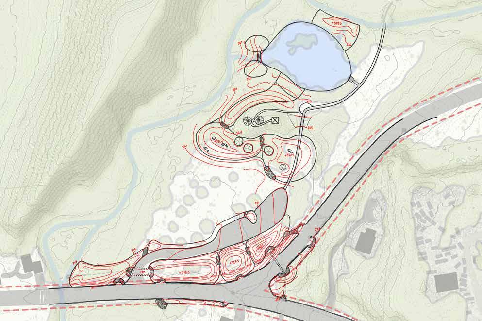
Creates a terraced bioretention basin system to treat and infiltrate roadway runoff, and balances increased use of the site for floodwater storage with the recreation needs of visitors to the sanctuary.
(1) The berm along the road is moved adjacent to the south side of the driveway, separating road runoff treatment within the TBBS from surface drainage within the sanctuary. (2) Catch basin ‘CB-A’ is canceled. (3) Catch basin 'CB-B' receives inflow from catch basins 'CB-C' and 'CB-D', and outfalls into the TBBS, which is planted with native wetland vegetation, helping to slow, filter, and absorb the captured runoff while also providing novel wildlife habitat and beautification. (4) Additional curb cuts allow any runoff that misses the roadway catch basins to access the TBBS. (5) The TBBS overflows through a low and wide culvert under the raised driveway entry into a vegetated bioswale which slopes gently toward East Brook. Both catch basins within the sanctuary are canceled as well.
(6) Catch basin ‘CB-E’ on the south side of Scantic Road is canceled and surface drainage here is captured in a vegetated bioswale within the ROW via a curb cut. The runoff exits the swale via a level spreader into the forested area south of Main Street before it flows overland into East Brook.
(7) The driveway entrance is widened, allowing easier and safer access. The driveway is regraded and raised to span a low culvert, preventing road runoff from entering the site, while also allowing overflows from the TBBS to flow safely underneath. The culvert has the added benefit of providing safe passage for wildlife like turtles and salamanders. (8) A small bioretention basin is installed to treat runoff from the regraded parking area. This overflows into a vegetated bioswale, and then to East Brook. Occasional vehicle access into the meadow occurs at an armored ford that crosses the swale close to the entrance.
(9) To reduce erosion, the trail from the parking lot to the bridge is raised into a boardwalk, allowing surface drainage to flow underneath it. (10) An observation deck with interpretive signage serves as an accessible resting point and education moment. A short spur winds from here up to the top of the adjacent hill where a small, kid-friendly birding tower has been added.
(11) Smiling Pond is disconnected from East Brook by regrading the current inlet. (12) The concrete weir is removed and replaced with a woody leaky weir, set at a lower level. Over time, this restores the pond into a wetland capable of capturing some of this storm water, and slowly releasing it over time. (13) For larger storm events, a secondary baffled overflow is added to the pond's southwest edge, feeding into a swale and bioretention basin system that further treats water before (14) overflowing into the meadow and brook as sheetflow.


The bioretention basins are intended to capture, slow, treat and infiltrate stormwater runoff. A conceptual sizing of the terraced basins was done based upon the limitations of the depth of excavation due the water table elevation onsite and MassDEP standards for stormwater infiltration basins which require a minimum 2 feet between the bottom of basins to the water table. Approximate calculations of the total volume of the terraced basin system is 6,750 cubic feet.
Based upon the rainfall data calculations referenced in the hydrological analysis performed by HSH, this system would be able to capture approximately:
→ 90 mins. of a 2-year size storm event at a peak flow rate of 1.2 cfs
→ 40 mins. of a 10-year size storm event at a peak flow rate of 2.9 cfs.
NOTE: These are approximate conceptual calculations only. They do not take into account exact considerations of site drainage conditions or actual engineered grading and design of the basins. Also, since as described in the analysis of this report, it is not feasible to bring water on site with the existing layout of the gray infrastructure, in this design alternative a portion of the gray infrastructure drain pipes from Scantic Road are diverted to a bioswale and not brought into the basins. This would make the peak flow rate calculations from HSH’s hydrological analysis not accurately applicable for this design. Further in depth analysis and engineering calculations will need to be done to properly size and engineer this system including the proposed renovations of the gray infrastructure, to properly manage peak flows from storm events.
Grading is conceptual, hydrological analysis of storm flows in addition to infiltration and soil test pits will need to be conducted here to check for water table depth and infiltration rates in order to determine size of these basins.


This project site encompasses the ROW surrounding the spot where Glendale Road crosses over East Brook, 1.5 miles northeast of Laughing Brook Wildlife Sanctuary, between intersections with Ames Road and Ridge Road. The box culvert spanning the brook at this location is showing signs of decay and is undersized, according to site assessments performed by HSH as part of the bridge replacement project. The dominant traffic pattern here is contained to Glendale Road, with occasional turns on and off of Ames and Ridge Roads. Both sides of Glendale Road are bordered by rural residential properties.
MassDEP has delineated wetlands on either sides of East Brook, and the adjacent property directly to the north of Glendale Road contains extensive horse pasture which appears to partially overlap with the delineated wetland based on observations of horses sinking ankle-deep in soggy soils within the paddock. The majority of the project site sits within the FEMA 100-year floodplain. South of Glendale Road is designated NHESP Priority Habitat
The ROW at this site is a mix of wetland habitat, roadside drainage ditches, maintained residential landscape, and utility poles. At the west side of the Glendale Road and Ridge Road intersection, buried electric and telephone lines occupy the ROW, as well as some MassDEP monitoring wells installed for remediation of the site after a small diesel spill that occurred in 2022.
Vegetation within the ROW is a mix of mown turf grass, wetland grasses, and ornamental plants. The landscape just beyond the ROW hosts an assortment of wetland plants, turf grass, tree canopy, and domestic horse-browsed grass.


At this site land cover is predominantly shrub marsh vegetation and ornamental plants, including mown turf grass. One significant exception to this is the agricultural grass within horse paddocks on an abutting property at the northwest corner of Glendale Road at Ames Road. The grass here is sparse due to horse browse and trampling. Land use surrounding the site follows the same pattern of mixed residential and small-scale agriculture. This pattern continues upstream of the site; however, there are talks underway for a new 80-acre solar farm to be installed in the area.
Impervious surfaces around the project site include the roadways, and rooftops and driveways of abutting properties. Water bodies include East Brook and its associated wetlands. As many rural residential zones in this area, there are no sidewalks, and people move through the area mostly by vehicle.


Slopes at this project site are relatively flat where Glendale Road crosses East Brook, and increase in steepness beyond the extent of the adjacent wetland to the east and west. South of the road, the wetland widens significantly, providing more volume for water storage by allowing flood water to spread out and slow down on its way down the watershed; however, the presence of Glendale Road to the north negates this benefit by holding water and channelizing flow through the undersized box culvert, a choke point. This effect has resulted in dangerous flood conditions in the past, with water over-topping the road. It is certain to do so again in the future.
Municipal storm drains collect runoff from the steeply sloped Ames Road to the east, and convey it under the intersection before outletting into the roadside ditch on the north side of Glendale Road. From here there is a narrow drainage ditch conveying this water to a small back-up culvert crossing under the road to the south. This drainage ditch has standing water in it, which may be due to multiple conditions: a high water table; the dam effect of the road; and collection of sediment and silt from the horse paddock due to the road's position in the valley, intercepting runoff which would otherwise filter into the wetland South of Glendale Road.
Additional storm drains collect runoff from Ridge Road, and the west side of Glendale Road north of the Ridge Road intersection. This drainage outfalls into East Brook south of the bridge, on the east side of Ridge Road, although the pipe opening is obscured by a pile of large rocks. Other sections of Glendale Road are un-curbed and surface drainage ditches collect road runoff. Notably, some runoff flows off the road at the north end of the bridge, causing significant erosion.
Upstream from the site, East Brook flows mostly uninterrupted from its headwaters 1.75 miles due north, with the exception of a small dammed pond at East Brook’s origin point. Approximately ~900 acres of land drains into East Brook before it flows through the culvert at the project site.
In order to determine exact amounts of runoff potential that drain into the site, a hydrological analysis needs to be performed of all local sub-watersheds, both of the existing gray infrastructure and of surface drainage swales.


NRCS maps the site soils as fine sandy loam, but surficial geology data from USGS indicates the site is on top of foreign fill material. Soil removed for percolation test pits appears consistent with this condition, noticeably deviating from the qualities predicted by NRCS. Notably, the soil on the north side of Glendale Road is very silty, dense, and gravelly. Percolation test pits indicated a drainage rate of 3 inches per hour.
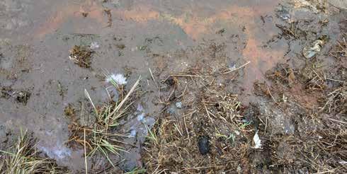
On the north side of Glendale Road, standing water was observed in the roadside drainage ditch outside of rainy conditions, potentially indicating the elevation of the water table, despite NRCS predicting a water table elevation more than three feet below grade and well draining soils. The water here is appears dark red, indicating high levels of iron, which is confirmed by a test of soil samples taken from this ditch. An oily sheen on the water's surface may be indicative of iron-oxidizing bacteria.
The height of the water table and density of silt at this test pit site are unsurprising when considering the presence of Glendale Road in the context of the wetland and stream it crosses, essentially functioning as a dam by intercepting runoff from the slopes north of the road. The nearly barren and likely compacted soils in the horse paddock may be more prone to erosion than other areas within this project site, and exacerbating sediment build-up within the ditch.


At this project site, Glendale Road spans a floodplain at a place where the landscape flattens and widens from its more narrow and steeply inclined character farther up in the watershed. Effectively, during large storm events Glendale Road and the box culvert function as a dam, and East Brook, which would naturally spread out and meander through this part of the landscape, is constrained to a narrow channel flowing through the aging and undersized box culvert.
To the east are steep forested slopes on rural residential lots. To the north, a residential horse ranch sits on a long, steady slope and overlaps with wetland habitat; the pasture extends into the regulated 100-foot wetland buffer. Road runoff is handled by a mix of gray infrastructure (i.e., catch basins and drain pipes) and “country ditch” vegetated swales. Soils and waters around the site are potentially contaminated from diesel, nutrient runoff, and iron deposition.

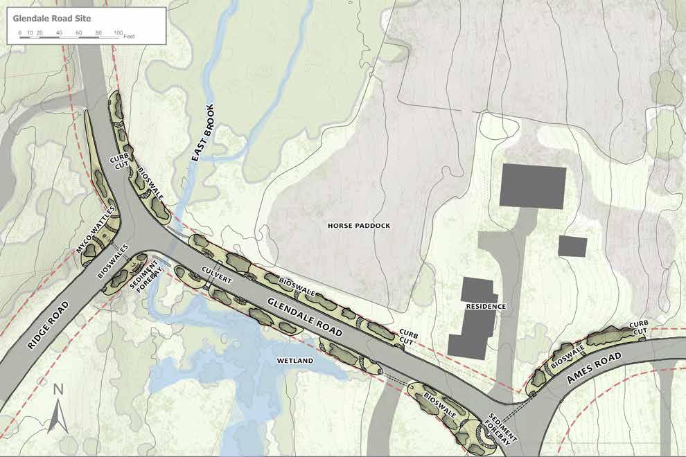
Makes the most of available ROW with a series of bioswales and bioretention basins treating runoff before it enters East Brook.
(1) The existing drain pipe outletting from the catch basin at the intersection of Ames road and Glendale Road is re-piped under the road to the south side, where it outfalls into a new bioretention basin within this wide section of ROW. (2) This basin then outlets through two bioswales, connected via a culvert under the abutter’s driveway, before draining overland into the wetland.
(3) On the north side of Glendale Road and Ames Road, a curb is added and a vegetated bioswale collects further surface runoff from the road through designated curb cuts, mitigating direct erosion along the road edge.
(4) The drainage ditch along the north side of Glendale Road, which currently ends at the back-up culvert, is extended all the way to East Brook, and the whole length of the swale is planted with native wetland vegetation to help treat surface runoff from the road and from the horse pasture. (5) The back-up culvert remains to allow drainage opportunities during large storm events.
(6) Along the box culvert, a curb is added. Armored curb cuts further mitigate erosion.
(7) By the intersection with Ridge Road, curb cuts bring surface drainage into shallow bioswales along either side of the road. (8) On the northwest side, this is a very shallow basin, due to the existence of buried utility lines preventing excavation. Myco-filtration straw wattles (i.e., rolls of netted straw inoculated with fungal spores) filter runoff from the diesel spill contamination zone. (9) On the southeast side, the existing boulders obscuring the outfall of the drain pipe extending from the catch basins are removed, and replaced by a sediment forebay with myco-filtration straw wattles to filter runoff before it drains into East Brook. These two bioswales are planted with attractive native vegetation to enhance the aesthetic appeal of this entrance to the subdivision further up Ridge Road.
(10) The ROW along Glendale Road's southern edge is similarly planted, but no swale is excavated due to lack of appropriate conditions.


Addresses increasing flood risks and wetland habitat concerns by replacing an aging box culvert and a section of Glendale Road with a bridge and boardwalk; and in doing so, suggests a collaborative relationship between the Town of Hampden and residents within the East Brook watershed.
The re-routed catch basin drain pipe at the east side of the project site and the additions along Ridge Road are identical to the first alternative. (1) Along the north side of Glendale Road a vegetated bioswale with check dams collects surface runoff alongside a new bridge before outletting into the brook and wetland.
(2) A portion of Glendale Road is rebuilt where it crosses East Brook, replacing the existing box culvert and sections of the road itself with a three-span bridge, widening the bankfull width of the brook, and allowing it to swell and spread out safely.
An important factor for flood mitigation and water quality enhancement at this project site (and the landscape downstream from it) is the health of the wetlands lining East Brook. (3) With the abutting landowner's cooperation, the fence line demarcating the horse paddock on the northern side of Glendale Road is moved uphill, beyond the extent of East Brook's wetlands. This area is replanted with native wetland vegetation. (4) Additionally, a vegetated buffer along the fence line reduces polluted pasture runoff entering the waterways.
To support a collaborative relationship with the abutting landowner, and address both their desire for safe horse passage to their property on the west side of East Brook and the health of the intervening wetlands, included in the design is (5) a wide and reinforced sidewalk capable of supporting horse passage, with direct access from the horse paddock. This takes the assumption that a likely funding source would be an MVP action grant, which would require the addition of sidewalks on either side of the road.


The grading plan laid out here is conceptual, and is not for construction purposes. Certain design analysis details would still need to be performed in order to assess the site and properly design and size the systems described here. This would include: a hydrological analysis of the existing drainage system and the corresponding size of watersheds along the road that are to be diverted to the swales and basins, and more in-depth soil profile testing to assess ESHW (estimated seasonal high water table).
Additionally, this grading plan does not include details about any regrading of the road that may occur as part of the bridge renovation and construction this design suggests, this would require further engineering and it may affect the rest of the layout of the design.


A mile northeast of Laughing Brook Wildlife Sanctuary, Bennett Road crosses over an unnamed tributary to East Brook as it winds through a mostly rural residential neighborhood of lot sizes between 1 and 78 acres. The landowner whose 1.3-acre property abuts the project site on the east side of Bennett Road verbally agreed to allow a portion of her front yard near the stream to be included in the project site and scope.
Under Bennett Road, a corrugated culvert carries the stream as it flows east to west on the way to its confluence with East Brook, a quarter-mile west of the site. On the east side of the road, the culvert inlet is heavily armored with large boulders. The west side is also armored, though not as heavily.
The ROW is mostly flat, and slightly lower in elevation from the road edges. Some curbs with cuts direct road runoff toward the stream. Vegetation in the area is mostly split between forest canopy and maintained ornamental residential landscaping, while the understory in the area directly beside the stream along its southeastern edge is routinely brushhogged and cleared by the abutter.
The entire working area of the project site is within the FEMA-100 year floodplain zone. The west side of the road is within NHESP Priority Habitat.


On the west side of Bennett Road, vegetation within the ROW is a mix of forest canopy; and on the east side, it's forest canopy around the stream banks, mown turf grass near the driveway, and grassy shrubland north of the stream. Beyond the ROW, vegetation is dense forest to the west of the road and along the stream to the east, mown turf grass and ornamental forbs and shrubs surrounding the residence on the east side of the road, a mix of ferns and grasses between the turf lawn and the stream, and dense unmaintained shrubland to the north of the stream.
The only visible water body is the stream. There is an active well in the resident’s yard east of Bennett Road which is described by the landowner as being 80 feet deep. Both Bennett Road and the driveway are asphalt surfaces. Along with the roofs over the house and the well, these make up the impervious surfaces within the project site. There are no sidewalks along the road, and automotive use of Bennett Road appears to be mostly local. The abutter reports regular speeding. The downhill nature of the road on either approach to the culvert crossing, combined with the lack of a center stripe may contribute to this condition.


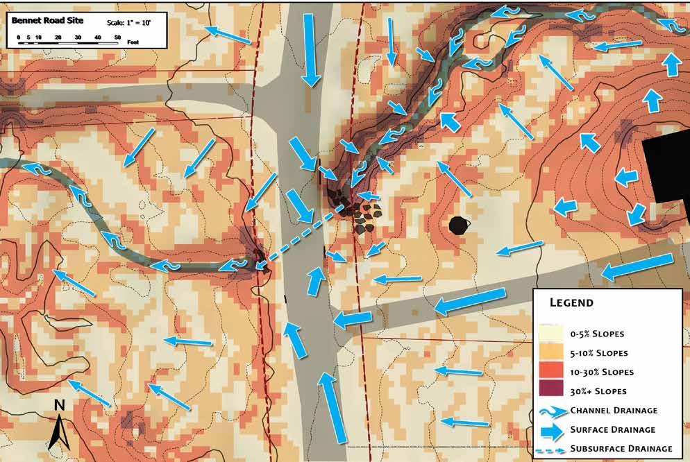
Slopes in the area are mostly less than 10 percent, with localized areas of steep slopes greater than 10 percent along the banks of the stream and around the house. The house and well sit on high points within the landscape, and most of the property is sloped downward toward the stream. Exceptions are the driveway, which is sloped toward the road, a shallow swale that runs along the north side of the driveway ending in a low spot by the road, and another shallow swale on the south side of the drive which similarly slopes down to a low spot by the road.
Bennett Road has its own low spot by the driveway, just south of where the stream passes through a culvert under the road. Curb cuts at this location allow stormwater runoff from the approximately 33 acres of land draining to this low spot on the road to flow overland to the stream below.
Despite these curb cuts, water puddles on the road, and the abutting landowner reports having observed passing cars splashing this runoff onto her property, which then puddles on her property in a low spot adjacent to the road. They are concerned about polluted runoff contaminating her well water and would like to see these drainage issues addressed in this project. Trails of matted grass aligned toward the low spot indicate that runoff from her lawn is likely also contributing to this pooling. There are no municipal storm drains along this section of Bennett Road. Curbs exist along the road north of the culvert crossing, while south of the crossing they are absent.
Upstream from the project site, a total of ~300 acres of land drains into the stream before passing through the culvert. On its way, the stream passes through the neighboring parcel to the south where it is channelized by vertical cement-reinforced stone walls, likely increasing the velocity of water flowing toward the project site. The abutter reports that a dam farther upstream blew out some years ago, causing flooding on her property.
Downstream, the stream continues to flow south and west for approximately 0.25 miles to its confluence with East Brook.
A more in-depth hydrological analysis needs to be conducted to better determine the exact size of the local watersheds, and the expected runoff during storm events.


NRCS describes the site as well-drained sandy loam, through directly north is poorly drained stoney sandy loam. USGS predicts surficial deposits of sand and gravel, while the road and ROW around the stream are artificial fill. The observed texture of soil removed for percolation test pits was very gravelly sandy loam. NRCS also predicts a shallow depth-to-water table, between 0.25 and 2.0 feet below grade, though no water was present in 12-inch deep test pits. Infiltration rates ranged from 3 to 6 inches per hour. Although hydric soils were not observed in the percolation test pit soils, it would still be prudent to conduct a wetland delineation prior to any future work at the site.


As an unnamed stream flows toward its confluence with East Brook, it passes under Bennett Road through a corrugated culvert flanked by steep stream banks. This location is a low spot in the road, and runoff which winds up here pools against the curbs despite curb cuts on either side of the road.
The adjacent property abuting the site to the east experiences unwelcome pooling. Factors include (but may not be limited to) runoff from the roadway being splashed on site by passing cars, and being a low spot in the yard at the end of a shallow swale.
Due to this condition, the abutter is willing to contribute part of her front yard to this design project if it will alleviate the pooling. Vegetation around the site is mostly densely forested to the west of the road and along the north side of the stream. On the south side of the stream the abutter maintains much of the understory of “wild” brush between the stream and her lawn, and has tended residential turf grass and ornamental landscaping around the house.


Makes the most of available ROW with a series of bioswales, treating runoff before it enters a tributary to East Brook.
This simple design alternative is limited to the ROW. (1) Vegetated bioswales are graded sufficiently to allow runoff from the road to enter via curb cuts and flow to the stream while being treated by native vegetation. (2) Additional curb cuts further away from the culvert in both directions along Bennett Road divert runoff into the swales before it reaches the low point in the road south of the culvert, mitigating pooling. (3) Additional rock armor is added around the culvert on either side of the road to mitigate erosion.


Extends beyond the ROW as part of a cooperative verbal agreement with the abutter to incorporate their property into the design. Anticipating increased storm intensities, the culvert is replaced and enlarged, allowing more stream flow during larger storm events. A raised speed table over the culvert slows down traffic on the road while also directing road runoff into the designed landscape.
(1) On the northeast side of the stream, a curb cut up the road from the culvert diverts most roadway runoff to a bioretention basin planted with native vegetation before overflowing down a rock-armored spillway into East Brook.
(2) An additional armored curb cut at the base of the speed table collects any other runoff sending it into a reinforced and replanted stream bank.
(3) On the southeast side a curb cut and sediment forebay diverts runoff from the road into a bioretention basin that also collects surface water coming down the hill on the abutters property before outletting into the stream upstream of the culvert. (4) The boulders currently lining the stream bank are repurposed to outline the bioretention basin, delineating the space while also giving it an aesthetic appeal.
(5) On the west side of the road a simple bioswale directs water via curb cuts into a vegetated bioswale within the ROW, similar to RDA 1 (see previous page).
The bioretention basins and swales are planted with a diverse array of native riparian and wetland plants that help filter the water and provide crucial wildlife habitat and beauty to these systems. These plants are also used extensively around the basins along the stream bank, mitigating erosion. Ongoing relationship building, outreach and cooperation will need to be conducted with the abutter to maintain the stream bank native vegetation buffer beyond the basins themselves.
The grading plan laid out here is conceptual, and is not for construction purposes. Certain design analysis details still would need to be performed in order to assess the site and properly design and size the systems described here. This would include: A hydrological analysis of the watersheds that drain towards the site and would be diverted to the swales and basins, and more in depth soil profile testing to assess ESHW (estimated seasonal high water table) and infiltration rates at proposed basin sites. Additionally, hydrological analysis would need to be considered for the watershed draining towards the culvert in order to properly assess what size culvert would be included in the replacement suggested in the design and how this may affect the grading of the road to accommodate it. This very well may change the layout of the curb cuts presented here and would require further engineering.


Bioretention is a practice that uses soils, plants, and microbes to treat stormwater before it is infiltrated and/or discharged. Bioretention basins (also called rain gardens in residential applications) are shallow depressions with well draining amended soil, a thick layer of mulch and planted with dense native vegetation. Stormwater runoff may be directed into the basin via pipes, curb cuts, catch basins and overland sheetflow. Vegetation absorbs and transpires a portion of the water while microbes living in the soil, and in symbiotic relationships with plant roots, break down nutrients and contaminants. Excess water not taken up by the vegetation percolates through the soil that acts as a
filter and infiltrates into the groundwater. During heavier storm events when the basin fills up, water may overflow into other BMPs or existing stormwater systems. Alternatively, they may be designed to be lined and outfitted with an underdrain where it is not suitable to infiltrate into the ground. Bioretention basins may be shaped to respond to the surrounding environment. Low-tech, decentralized bioretention basins are also less costly to design, install, and maintain than conventional stormwater technologies that treat runoff at the end of the pipe.

Pollutant Removal: Properly designed, bioretention basins remove phosphorus, nitrogen, metals, organics, and bacteria including up to 90% removal of total soluble solids (TSS) with adequate pretreatment (catch basin and/or sediment forebay)
Discharges Near or to Critical Areas Good option for discharges near cold water fisheries.
Depth of Soil Media Minimum of 2 to 4 feet, depending on site drainage conditions.
Sizing: Should be 5 to 7% of the area draining into it and have the ability to capture and treat the first 0.5 to 1 inch of runoff from a storm event. Should be designed to have a ponding depth of 6 to 8 inches (depending on site conditions more or less ponding may be appropriate
Depth to Water Table Basins must have a minimum of 2 feet depth from the bottom of the basin to the seasonal high water table.
Drainage Infiltrating bioretention basins must be designed to drain within 72 hours.
Vegetation: Aim for a 60% woody, 40% herbaceous species mix. Using masses of single types of plants rather than interplanted, especially herbaceous species, simplifies maintenance direction if you have intro-level landscape maintenance workers. If interplanting, consider drawing on a community of plants that would naturally grow together to ensure the maintenance regime can be set up for long term success. Plan for salt tolerance in basins catching parking and road surface runoff.
Maintenance: Plan for a low-maintenance environment and provide maintenance access. Proper selection of plant species and support during establishment should minimize if not eliminate the need for fertilizers and pesticides. Remove invasive species as needed to prevent their proliferation in the basin. Remulch void areas as needed. Remove litter and debris monthly, remove and replace any dead vegetation twice per year (spring and fall). Never store snow in bioretention basins. Care must be taken during road plowing to prevent snow from being plowed into basins.
A bioswale (grass swale or water quality swale) is a combination treatment and conveyance BMP. As opposed to a general drainage swale which acts solely as conveyance, a Bioswale conveys water along a vegetated open channel while also slowing, filtering and infiltrating water. It may include a series of cells within the channel formed by check dams or berms which further slow the water flow, increasing sediment dropout and infiltration. Bioswales may collect
water runoff from a pipe, directly from a roadway, or be connected to other BMP’s as part of a complete stormwater system. Roadside bioswales provide water quality and quantity control benefits, while reducing driving hazards by keeping stormwater flows away from street surfaces and can be used to retrofit existing drainage channels and grass channels. Pollutant removal in these swales relies on sedimentation, adsorption and microbial breakdown.

Pollutant Removal: Achieves 70% TSS removal when provided with a pretreatment device such as a sediment forebay with a check dam.
Discharges near or to Critical Areas: Recommended as treatment for coldwater fisheries.
Slopes: The topography of the site should allow for the design of a swale with sufficient slope and cross-sectional area to maintain a non-erosive flow rate: with side slopes no greater than 3:1 and longitudinal slope as flat as possible and at maximum 5%.
Sizing: Size wet swales to convey the 2-year and 10-year 24-hour storm.
Depth to Water Table: Two main types of bioswales exist: dry & wet Swales. A dry swale may be lined and includes a treatment soil depression with an underdrain and the bottom should not be within 2 to 4 feet of the seasonal high-water table. A wet swale may be used in areas with higher water tables and is constructed directly into existing soil.
Drainage: While these swales are used to convey water, ponding areas near check dams should drain within 72 hours.
Vegetation: Bioswales may be grassed and or planted with drought-tolerant native vegetation. In sections of the swale near check dams, include watertolerant and/or wetland species. Along roadways, select vegetation that is salttolerant. If grassed, grasses should be kept at maximum 6 inches tall as taller grasses may fold over during flow and prevent proper sedimentation.
Maintenance: Inspect swales during the first few months after installation to ensure that the vegetation in the swales becomes adequately established. Thereafter inspect swales twice a year. During inspection check for slope integrity, soil moisture, and vegetative health, as well as ponding and sedimentation. Mow grass in dry swales as needed, Wet swales may not need mowing depending upon vegetation. Do not mow grass shorter than 3 to 4 inches as this may limit the ability of the vegetation to reduce flow velocity. Remove sediment and debris once a year. Maintenance access must be designed as part of the swale, and include an area at least 15 feet wide. In the spring, replant any areas that died off due to salt accumulation from road deicing.
A sediment forebay is a pretreatment structure used before delivery of runoff to other BMPs. It consists of an excavated pit, bermed area or cast structure combined with a weir, designed to slow incoming stormwater runoff and facilitate the gravity separation of suspended solids.

Pollutant Removal: MassDEP requires a sediment forebay as pretreatment before stormwater is discharged into infiltration basins. They can remove coarse sediment fractions but not soluble pollutants.
Design: A typical forebay is excavated below grade with earthen sides and a stone check dam. It should be able to withstand 2-year and 10-year storm velocities without scouring. Side slopes should be no steeper than 3:1.
Sizing: At minimum they should be able to hold 0.1 inch of runoff per acre of impervious surface draining into them.
Depth to Water Table: Bottom of forebay should be at a minimum of 2 feet above the seasonal high groundwater level.
Drainage: Forebays should be designed to dewater between storms, with a dewatering time of 72 hours at maximum (based upon 0.5-1 inch of runoff in a 24-hour period)
Vegetation: Use only grasses. Other vegetation will reduce the storage volume in the forebay. Stabilize earthen slopes with grass seed mix. Selected grasses should be able to withstand periodic flooding and be drought tolerant.
Maintenance: Frequent maintenance is essential and thus forebays need to be designed to allow easy access for sediment removal. Inspect sediment forebays monthly and clean sediment out at least four times per year. Stabilize the floor and sidewalls of the forebay after cleaning, otherwise the practice will discharge excess amounts of suspended sediments. When removing sediment, it may be necessary to reseed the bottom of the forebay after removal. Conduct periodic mowing of embankments (generally two times per year) to control growth of woody vegetation on embankments; keep grass height at a maximum of 6 inches and set mower blades no lower than 3 to 4 inches.
A check dam or leaky weir is a small dam constructed across a drainage ditch, swale or channel to lower the velocity of flow. They cause water to pond in small pools, and then slowly seep through the dam or infiltrate into the soil. They dissipate the energy of flow, allow suspended sediment particles to settle

out, promote infiltration and enhance water quality treatment volume. They can be a simple way to reduce downstream flood peak flow by temporarily storing water and are relatively easy and inexpensive to construct.
Usage: Can be used in small open channels that drain 10 acres or less or channels where stormwater velocities exceed 5 feet per second. They should not be used in live stream channels.
Sizing: In a swale the check dams should be used in series, with the toe of the upstream check dam at the same elevation as the top of the downstream check dam.

Spacing: In a channel, they should be spaced so that the bottom of the upstream check dam should be at the same elevation as the top of the downstream check dam. General check dam spacing can be calculated by dividing the height of the structure by the slope percentage of the channel.
Material: Check dams can be composed of wood, concrete, stone, or other non-erodible material. Rock check dams should consist of well-graded stone consisting of a mixture of rock sizes.
Design: Install check dams across the entire width of the channel, perpendicular to the flow. Exercise care in designing the ends of a check dam to ensure that it is long enough and adequately anchored to prevent ponded water from scouring the soil at the ends, and flowing around the dam, even during large storm events.
Rock check dams: The sides of the check dam must be higher than the center in order to make sure that the possible water flowing downwards is always directed over the center of the dam. Provide a minimum of 6 inches of freeboard
Wooden leaky weirs: Logs should span width of channel and staked into side slopes for stability. Bottom logs should be buried in the channel to prevent bed erosion. An alternative design includes live staking the weir with easily rooting plants such as willows, essentially creating a living fence.


Vegetation: By causing water to pool, and allowing sediment to drop out, check dams can help promote vegetation to get established by becoming sources of concentrated nutrients. If vegetation does establish, this can help mitigate erosion in the channel and stabilize the check dam, but will require inspection as it can also raise water ponding levels.
Maintenance: Inspect check dams after every significant rainfall event. Repair damage as needed. Remove sediment as needed.
“Mycofiltration and mycoremediation are low-cost and low-tech emerging stormwater solutions that utilize fungi’s mycelium, or fungal webs, as biological and chemical filters within organic matter and soil substrates to improve water quality. As such, mycofiltration could easily be layered into existing MassDOT stormwater control measures (SCMs) such as sediment control
barriers, bioretention cells, or compost blankets to assist in filtering out small particulates; destroying pathogens; mitigating phosphorus and nitrogen impacts; capturing heavy metals; and breaking down pesticide, herbicide, and hydrocarbon pollutants.” *

Usage: Mycofiltration wattles may be used in conjunction with other treatment or conveyance BMPs including bioswales, bioretention basins, check dams and sediment forebays. Mycofiltration may also be applied as inoculated wood chips used for mulch or in compost soil amendments.
Pollutant Removal: Research has shown that oyster mushrooms (Pleurotus ostreatus) performed the best at removing E. coli and other coliform bacteria. By improving soil organic matter content, fungi add to the natural denitrification process which can lead to nitrogen removal. Saprophytic (decomposer) fungi, secrete enzymes which break down petroleum hydrocarbons. Mycorrhizal fungi (living in symbiosis with plant roots) improve plant tolerance to growing under salt stress, this can help with improving plant growth in vegetated roadside bioretention areas dealing with de-icing salt residues.
Design:
Myco Wattles: A burlap wrapped wattle is inoculated with saprophytic fungi and staked in place in the path of the flow of water along a contour similar to compost filter tubes and other erosion control measures, or in a bioswale along the edge of a check dam.
Mycofiltration Bioretention Basin: Enhancing the performance of standard bioretention basins, soils, compost or mulch can be inoculated with mycorrhizal or saprophytic fungi and applied to the basin.

"Diesel Spill Report at Glendale Road," Clean Harbors Environmental Services
"Hydrological Assessment of Existing Drainage System at Laughing Brook," Howard Stein Hudson
"Hydrological & Hydraulic Analysis for Main Street Bridge over East Brook," Howard Stein Hudson
"Minnesota Stormwater Manual," Minnesota Stormwater Steering Committee
"Planting Design: Guidance for Bioretention and Rain Gardens," Rainscapes, Department of Environmental Protection, Montgomery County MD
"Plant List for Bioretention," Rainscapes, Department of Environmental Protection, Montgomery County MD
"Stormwater Handbook Volume 2. Ch. 2, 'Stormwater Best Management Practices,'" MassDEP
"Top 10 LID Recommendation Sites for Hampden," Howard Stein Hudson
"Using Mycofiltration Treatment for Stormwater Management," MassDOT
"Buffer Zone Restoration Guidelines," Wellesley Wetlands Protection Committee, Wellesley, MA
"Planting Design Templates for Rain Gardens," Rainscapes, Department of Environmental Protection, Montgomery County MD
"The Massachusetts Buffer Manual: Using Vegetated Buffers To Protect Our Lakes and Rivers," Berkshire Reigonal Planning Commision, MassDEP
"Stormwater BMP Design for Cold Climates," US EPA Office of Wetlands, Oceans and Watersheds
