Towards a Lively Architecture - Exploring Response in Bent Wood Assemblies | Thesis by David Heaton

Page 1

To w a r d s a L i v e l y A r c h i t e c t u r e

Exploring Response in Bent Wood Assemblies

By: David Heaton September 2017 A thesis submitted to the Faculty of the graduate school of The State University of New York at Buffalo In partial fulfillment of the requirements for the Degree of Master of Architecture School of Architecture and Planning

i


ii

ACKOWLEDGEMENTS I would like to first thank my mother and father for their endless support throughout my academic career. They have truly helped me get to where I am today, and for that I am forever grateful. I would also like to thank Nicholas Bruscia and Omar Khan for their wisdom and guidance throughout this process. Thanks for giving me the freedom to explore, insightful conversations and inspiration to succeed. Thank you to my best friend and partner Vivi for her emotional support throughout this project and for letting me come home and forget. Also, a big thanks to all of the friends I have made during my time here and to all of my professors. You have all created fond memories and pushed me to be a better person and designer.


ACKOWLEDGEMENTS (cont.) Last but not least, I would like to thank all of my friends and students that came to help me construct the final installation. Without you this would have been impossible. Thank you: Lydia Ho John Lauder Dan Vrana Lesley Loo Erik Louwagie Christopher Sweeney Andrew Mamarella Adara Zullo Nicholas Hill Max Lu Nicole Henriquez Michaela Senay

iii


iv

TABLE OF CONTENTS 1.0_ABSTRACT 1.1_TOWARDS A LIVELY ARCHITECTURE 1.2_MATERIALLY DRIVEN RESPONSIVE ARCHITECTURE 1.3_WOOD AND EMBEDDED RESPONSIVENESS 1.4_TENSILE PROPERTIES / ACTIVE BENDING 1.5_FORCE DRIVEN DESIGN

viii 2 4 6 8 9

2.0_METHODOLOGY 2.1_ACTIVE FIELDS - PERCEIVED MOVEMENT 2.2_APPLIED FORCES

10 12 16

3.0_EMBEDDED FORCES: LIVELY TENDENCIES

24

4.0_RE-EVALUATING BEHAVIOR THROUGH TECTONICS 4.1_BACK TO BASICS: PHYSICAL MATERIAL TESTING 4.2_PHYSICAL TO DIGITAL CALIBRATION 4.3.1_UNDERSTANDING MOVEMENT IN THE SYSTEM 4.3.2_SINGLE DIRECTION SPREAD 4.3.3_DOUBLE DIRECTION SPREAD - UNIFORM 4.3.4_DOUBLE DIRECTION SPREAD - NON-UNIFORM 4.3.5_END APPLIED FORCE 4.3.6_NON-LINEAR SPREAD 4.3.7_NON-LINEAR SPREAD - NON-UNIFORM 4.4_VARIABLE STRIP WIDTH

30 32 34 36 38 40 42 44 46 48 50


v

5.0_FINDING A SYSTEM AT A LARGER SCALE 5.1_LARGE SCALE PROTOTYPE 5.2_PROTOTYPE PROCESS 5.3_PRECARIOUS STRUCTURE 5.4_AMPLIFYING FORCES

52 54 56 58 62

6.0_SITE AND SPACE

64

7.0_FINAL PROTOTYPE 7.1_REALIZATION 7.2_CONCLUSION

72 80 90

8.0_BIBLIOGRAPHY

92


1.0_ABSTRACT

vi The field of responsive architecture1 has explored many avenues of response including media screens, light sensitive facades and reactive wall systems, but has not extensively addressed tectonics2 as a vehicle for response. This thesis will address issues of response through the exploration of delicate, branching, aggregate structures that inherently embody notions of “Liveliness”. Using wood for its natural tensile properties, models will be developed that explore varying “precarious” branching typologies that are conducive to response. Liveliness will first be looked at through the application of forces to the system and understanding how the transfer of forces begins to animate the structures.

1 Nicholas Negroponte proposed that responsive architecture is the natural product of the integration of computing power into built spaces and structures, and that better performing, more rational buildings are the result. Negroponte, Nicholas. Soft Architecture Machines. Cambridge MA: MIT Press, 1975. 2 Kenneth Frampton wrote, “Needless to say, we are not alluding here to mechanical revelation of construction but rather to a potentially poetic manifestation of structure…as an act of making and revealing.” Here, tectonics is not simply the detailed way in which elements come together in part of a system (i.e. the facade, structural system, etc.) , but rather changing the way the tectonics of the entire system are thought of to reveal a Liveliness.

These investigations will be used to inform digital simulations that investigate material tendencies and possible structural aggregations. These digital simulations will also be used as a tool to study the transference of forces and energies through both stable and unstable systems that begin to reveal liveliness in the reactions and tendencies of the system. Light, shadow, overlap of materials, and opacity will also be explored for its potential to register a visual liveliness and alter our perception of space. Using the gained knowledge from the model studies and simulations, a full scale immersive installation is intended to embody liveliness through branching tectonics with carefully designed part-to-whole relationships and the use of light and density to affect visual perception. The goal of the research is to question typical notions of response through the development of a new lively tectonic that changes the way we perceive space. By perceiving space as living, we begin to give it more value and develop a new sense of empathy in architecture.


1

fig. 01 - initial study model


1.1_TOWARDS A LIVELY ARCHITECTURE

2

The notion of “Liveliness” in architecture has its roots in the theories that helped shape the area of responsive architecture. One of the first examples can be found in Cedric Price’s and Joan Littlewood’s unrealized 1964 Fun Palace. The Fun Palace was a theater consisting of a system of movable containers, scaffolding, and a crane. This framework was meant to allow the occupants to reorganize the space based on their needs and activities. The building acted as a tool, a framework for interaction rather than enclosure. (Beesley, Khan 2009) Price and Littlewood seemed to be more concerned with orchestrating action and creating a place for interactions to take place. It was a feedback system between users occupying the space with ever-changing needs and a framework that was responsive and changed to meet those needs. This idea of architecture as a responsive system was picked up and pushed further with the influence of Cybernetics. Cybernetics is the study communication and control in a system in order to achieve a goal. In order to find out if the goal is being achieved there is need for feedback in the system and thus the idea of a constant information feedback loop was developed in order to allow for the system to complete a goal. This was taken on in architecture and the idea of a feedback loop in architecture resulted in the idea of responsiveness. Cybernetician Gordon Pask stated, “Architects are first and foremost system designers.” (Pask, 1969) This suggested an approach to design where the architecture is not focused on making objects, but rather interested in architecture as a system. He was interested in the “operational” capacity of architecture and argued that architecture could be treated as a program or a system in which specific variables and parameters could be set to create spaces. The idea that architecture was a framework for constantly changing interactions developed into a framework of spatial change. This created a field where modification would generate possibilities instead of fixed conditions. (Parlac, 2016) Here the ‘event’ taking place inside of architecture is now what is being designed for. Ignasi Morales speaks about this in what he calls “weak architecture”; an architecture that embraces the “precarious nature of the event” by not calling attention to itself. (Sola-Morales, 1987) He suggests that the ability to resonate and amplify situations was a stronger strategy for architecture rather than attempting to contain and control situations. (Beesley, Khan, 2009)


3

fig. 02 - Cedric Price’s and Joan Littlewood’s unrealized 1964 Fun Palace.

During the 1970’s Bernard Tschumi wrote that architecture does not exist without events. It is meant to house actions and activities. Since without events architecture would not exist, Tschumi sought to make the architecture intensify the events that took place within it and that events could alter the architecture. Architecture is the combination of spaces, events and movement. Marcos Novak explored a new form of event based architecture in the 90’s known as liquid architecture. He described it as, “[Liquid architecture] is a symphony of space, but a symphony that never repeats and continues to develop. If architecture is an extension of our bodies, shelter and actor for the fragile self, a liquid architecture is that self in the acting of becoming its own changing shelter. Like us, it has identity; but its identity is only revealed fully during the course of its lifetime.” (Benedikt, 2009) He explored ideas of events and interaction in virtual architecture. He introduced sophisticated notions of event, interaction and customization to architectural discourse. (Sterk, 2009) Greg Lynn approached a similar topic through the idea of “animate form”. Lynn explains, “Animation is a term that differs from, but is often confused with, motion. While motion implies movement and action, animation implies the evolution of a form and its shaping forces; it suggests animalism, animism, growth, actuation, vitality, and virtuality.” (Lynn 1999) He approached architecture directly by developing ways to bring to life the ideas he spoke about

through new forms of digital modeling and fabrication. He used the smoothness of dynamic form to imply and suggest animism in architecture. He added a language of dynamics, fields, and forces to the architectural discourse. (Sterk, 2009) Coming out of the cybernetic tradition, having worked with Price and Pask, John Frazer stated, “architecture should be a living evolving thing” (Frazer, 1995) The idea of architecture that did not just respond to your presence, but could actually perceive your presence and interact with you began to develop. Architecture was no longer a single place or event, but could act as a living ecology that actively participates with its surroundings. (Vera, 2016) The work of Phillip Beesley suggests notions of living architectures and ecologies. His various installations mimic living organisms by adopting their likeness and movements. One of his projects Hylozoic Soil creates “jungles” of individual pieces that interact among themselves and interact with inhabitants through small life like movements in single elements but also as a whole ecology with a chain reaction of lights and energies registering a person’s presence. The individual reactions change the resonance of the collective surface. (Beesley, Khan 2009) There is a sensitivity to the work where individual pieces are stretched near their limits and operating near failure. They create “precarious” fields.


1.2_MATERIALLY DRIVEN RESPONSIVE ARCHITECTURE

4

PERFORMATIVE ACTOR:

fig. 03 - Bloom (Doris Sung, 2011)

Recent developments of “performative” materials offer an opportunity to design material behaviors as opposed to choosing materials based on their static properties. These performative materials behave in response to the active energy fields existing within and around the “systems” we program. However, the introduction of these materials calls for careful consideration of all of the building elements we use. The behaviors exhibited within “smart” materials can be physically programmed or even naturally found in materials such as wood. These materials exist in a variable environment and therefore we should explore the embodied potential each of these materials has to respond to its environment if we are to design with material behaviors in mind. This idea of performative materials changes our notion of materials as a static element to one in which the material acts as a mediator. (Rashida, Patel 2013) This allows us to view the interface between materials, people, and their environment all as actors within a system. Material information should become a generative driver rather than an afterthought in design computation. (A. Menges, 2012) If we begin to understand the way materials naturally react, design can enhance these natural responses and reactions. This can be done through the development of new tectonic types designed for material behavior. This would mean a shift from the current typologies of frames designed specifically for a material’s static properties to new forms that welcome their dynamic properties.

Synthetic Material Response:

fig. 04 - Smart Screen III (Decker Yeadon, New York, 2010)

The following section contains examples of materially driven responsive projects using synthetic man made materials as passive or active actuators in a system.


5

Bloom (Doris Sung, 2011) is a structure designed for shading and ventilation. This project incorporated bimetallic strips as its actuator. This is a process by which two different types of metal with different expansion coefficients are attached. As heat is applied, the metal expands at different rates, causing deformation. Bloom consists of a large surface array of bimetallic panels that when heated by the sun, curl to allow heat to escape the space and as they cool, close again. Smart Screen III (Decker Yeadon, New York, 2010) uses shapememory alloy (SMA) wire to replace the mechanism inside of window blind units in a building. SMA is a material that “remembers” its original shape returns to it when heated. Instead of having a mechanical solution to raise and lower blinds, the SMA wire replaces that assembly. As the sun heats the facade the wire slowly retracts raising and lowering the blinds. Living Glass (David Benjamin and Soo-in Young 2004-2005) is a project that incorporates shape memory alloys. These allows have the ability to recall their original shape when heated. This process can happen repeatedly giving the materials a ‘memory’. Living Glass uses a lightweight silicon skin with gill like slits in it as a building ventilation system. The dynalloy flexinol wires are electrically heated to cause the slits to open, ventilating the space. The opening and closing of the system is regulated through sensors that measure the space’s carbon dioxide levels. Shape Shift (ETH Zurich, 2010) is a project exploring the use of electroactive polymer (EAP) as a building shading and ventilation system. EAPs are a type of polymer that can alter its shape based off of an electrical charge. This system consists of an array of biologically inspired panels. Each panel is framed in acrylic with the center being layered EAP. When a charge is placed, the system can morph its shape.

fig. 05 - Living Glass (David Benjamin and Soo-in Young 2004-2005)

fig. 06 - Shape Shift (ETH Zurich, 2010)


1.3_WOOD AND EMBEDDED RESPONSIVENESS

6

Traditional wood building techniques are defined by old methods of production and are typically constructed to create rigid frames to resist movement. This can be seen in the way we construct homes as rigid frames attached together to enclose space. This can also be seen in the hulls of wooden boats, and although wood could be bent into complex shapes, its primary purpose is to maintain a rigid structure. The responsive environment makes use of new forms of production that allow us to control materials and design for very specific moments. We are no longer bound by repeated rigid frames. New structures are not reliant on a central structure but can now be supported through the distribution of forces across multiple structures that allow for change and deformation. Hygroscopic Behavior: Hygroscopy in wood is the ability to alter its volume when absorbing or dismissing water to the environment. This alteration results in a non-uniform, three axis deformation of its body which is described as anisotropy and affects its structure and strength. (A. Menges 2009) An example of this can be found in conifer pine cones. The pine cone’s seeds rest behind the scales. After falling from the tree, the scales open and close multiple times. It will open when dry and close when wet. In traditional wood construction this process resulted in the warping of wood members, rendering them unusable under certain circumstances. However, by understanding this material behavior, we can begin to ‘physically program’ the direction of the grain to react in predetermined ways. The dimensional change of wood is directly proportional to changes in moisture content. (A. Menges, 2012) This allows for repeatable and precise physical responses that can be used as design parameters. Warped:

Warped: Experiments in Ply Construction was a thesis project conducted by Matthew Hume in 2007 at the University at Buffalo. Here the response of wood veneer was explored as a design parameter by exploiting the material’s natural hygroscopic tendencies. By specifically arranging the direction of wood grain, he was able to control the way the wooden system reacted to moisture in the environment.


7

fig. 07 - Warped: Experiments in Ply Construction


8

1.4_TENSILE PROPERTIES / ACTIVE BENDING

Due to the fiber direction caused by the distribution of cells, wood inherently has directionality. This directionality can be understood as variable strengths and stiffness. (A. Menges, 2012) This allows us to design structures that incorporate pliability as opposed to resist it entirely. Wood also shares properties with synthetic composites, such as glass-fiber-reinforced plastics which have a high strain at failure and low stiffness, but maintain a high amount of structural capacity. (A. Menges 2012) These properties lend themselves to constructing systems using bending methodologies. This creates an embedded energy in the wood through which the internal forces can be used to add stability. This added strength allows for the creation of very lightweight, thin structures with a high structural capacity.

ICD/ITKE Research Pavilion 2010:

fig. 08 - ICD/ITKE Research Pavilion 2010

This research pavilion demonstrates an alternative approach to computational design. Here, the computational generation of form is directly influenced by the physical behavior and characteristics of materials. The structure is entirely based on the elastic bending behavior of birch plywood strips. The resulting bending active structure is made up of very thin elastically bent plywood strips.


9

1.5_FORCE DRIVEN DESIGN

Tension driven material systems are not new in architecture. They were widely explored and implemented in the tensile membrane structures designed by Frei Otto and the Institute for Lightweight Structures. Force can be used as a way of defining form that has multiple states of equilibrium. This means that the systems that generated the form and the systems of operations become intimately aligned. (Ahlquist, Menges 2012) This creates interdependencies in any force driven system whereby localized instances of change can affect the overall homeostatic performance. Here form is no longer static, but rather serves as a system itself that embodies the interactive systems by which it was formed and how it operates. (Ahlquist, Menges 2012) Force driven systems become sensitive to the surroundings and have the ability to react with energies being put into and taken away from it. The systems create multihierarchical material behaviors that interact between themselves and the surroundings, or rather a collection of internal and external energies acting in a constant state of fluctuation. (Ahlquist 2016) Deep Surface Prototype: Project 1: This project studies the possibility of advanced geometric complexity within a continuous tensioned surface structure. Stability in a purely tensioned structure comes from the equilibrium of forces.

fig. 09 - Deep Surface Prototype: Project 1


10

2.0_METHODOLOGY

Overview: This thesis seeks to understand what “Liveliness” is in architecture and how we can design towards that notion. The main method of inquiry is to construct models using wood for its embedded tensile properties to explore various “precarious” branching typologies that are conducive to response. Each model will be evaluated and studied in how it responds to loading and its ability to amplify forces in and around the structure. These studies will be examined for its behavior tendencies and how each begin to demonstrate particular forms of Liveliness. Geometry, light, shadow, movement, and the visual perception of movement will all be explored through a series of exploratory models. Using the gained knowledge from the model studies, a full scale, immersive installation will be built that embodies liveliness through its branching tectonics that explore part to whole relationships as well as the use of light and density to affect visual perception.


11

fig. 10 - drawing describing model movement


2.1_ACTIVE FIELDS - PERCEIVED MOVEMENT

12

Moving forward with the idea of interconnected branching structures, a new type of model was developed that explored thin flexible wood elements interconnected in a field condition. These thin elements shown in figs. 11+12 created a light, bouncy system where subtle movements were visually amplified due to the repetition of self-similar units. This model introduced several generative ideas into the thesis such as exploring the flexibility of the material, using the sinuous nature of the geometry to study varying types of wood in the same configuration, and how the system began interacting with forces. By applying forces to various parts of the model, long exposure photographs were taken that began to suggest the visual effect of overlapping members and their subtle motions when activated by an external condition. Liveliness was explored in these experiments by viewing how subtle forces were amplified, not only through motion but through a visual field condition created by the repetition of many units. Rather than seeing localized changes, displays of liveliness were noticed throughout the entire system.


13

fig. 11 - initial study model showing interwoven field condition

fig. 12 - model showing the field condition response to force


14

fig. 13 - moirĂŠ pattern

In these experiments, fabric was chosen for its ability to stretch and reveal areas of high and low tension (taut vs. slack) as well as its ability to filter light and allow for varying visual opacities. The first studies were purely visual explorations each addressing the moirĂŠ effect in combination with or without color as a possible method to visually amplify forces. The model shown in fig. 16 is composed of a grid of colored threads that created a visual gradient. These experiments explored liveliness as an amplification of forces across a field condition. The field seemingly moved as you walked around it due to the overlapping fibers. Here, the onlooker became the activator of motion rather than a physical force causing motion within the system. As a small force was applied the entire field comes alive as a whole displaying that change.


15 fig. 14 - fabric study model

fig. 15 - study model exploring stretch fabric patterns

fig. 16 - model exploring color and its visual depth


16

2.2_APPLIED FORCES

This next grouping of experiments sought to replace direct force being applied to the system and begin to find ways of internalizing forces. If we accept that forces exist in homeostasis within a system, then any additional external forced would cause an imbalance and begin to shift all existing forces until the system found a new homeostasis. The first attempt to embed forces within the system came in the form of hanging weights. A new model was constructed that mimicked the earlier field model, however it now incorporated connection elements for hanging weights to be applied at multiple points in the system. Also, in this version, heat shrink tubing was enhanced with mechanical connections to ensure strength within the wood elements as well as provide support for hanging weights. More importantly was the system’s ability to demonstrate notions of “Liveliness�. The resonating weights within the system caused pendulum-like interactions that create subtle movements throughout the entire system. Now a small force applied caused reverberation in the whole and began to amplify small movements.


17

fig. 17 - model testing behavior of the new strip typology

fig. 18 - weights were introduced into the system to embed forces

fig. 19 - these systems were tested until failure


5-1/4” 1/4” 1/4”

T H E S I S

M2 SS Bolt M2 SS Washer M2 SS Nut 1/32” 3-Ply Birch

EXPLORATION OF RESPONSE THROUGH BRANCHING_TECTONICS This thesis will address issues of response through the exploration of delicate branching aggregate structures that inherently embody notions of “Liveliness”

NICHOLAS BRUSCIA OMAR KHAN

11 - 1/4”

CHAIR: COMMITTEE:

Abstract: 
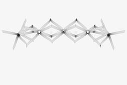
The field of responsive architecture has explored many avenues of response, but has not directly addressed the tectonics of our built environment. This thesis will address issues of response through the exploration of delicate, branching, aggregate structures that inherently embody notions of “Liveliness”.

A2

3/4”

5/16” Shrink Tubing 1/4” Basswood Stick

The goal of the research is to question typical notions of response and to introduce a new lively tectonic that will allow us to design more immersive spaces and begin to open a different dialogue on how we construct for response.

23.5”

Using the gained knowledge from the model studies and simulations, a full scale immersive installation will be built that embodies liveliness through its branching tectonics and use of color to affect visual perception.

3/8”

Using Wood for its embedded tensile properties, models will be developed that explore varying “precarious” branching typologies that are conducive to responsive environments. These investigations will be used to inform digital simulations, and these simulations will then be used to study the material capabilities and possible structure aggregations. Color will also be explored for its potential to register a visual liveliness and alter our perception of space.

M2 SS Eye Hook

UNIT TYPOLOGY

DIAGRAM OF SINGLE UNIT

A2

TOP VIEW OF MAIN UNIT IN AN ARRAY

A3

TOP VIEW OF CONNECTION OF 4 UNITS

A4

SIDE VIEW OF MULTIPLE UNIT ARRAYS

A3

18

1/4” 1/4”

10 - 3/4”

A1

M2 SS Nut M2 SS Washer M2 SS Bolt

A1

A4

M2 SS Bolt M2 SS Washer M2 SS Nut

1/32” 3-Ply Birch

5/16” Shrink Tubing 1/4” Basswood Stick M2 SS Eye Hook

M2 SS Nut

A5

AXON DIAGRAM OF UNIT ARRAY

M2 SS Washer M2 SS Bolt

A5 fig. 20 - drawings describing the strip units and their aggregation


19

fig. 21 - model exploring effect of 3lbs. of symmetrical hanging weights

fig. 22 - model exploring effect of 3lbs. of asymmetrical hanging weights


20

fig. 23 - metal cables were introduced along with more vertical layers resulting in both tension and compression forces


21

fig. 24 - detail view


22

fig. 25 - models were created to explore alternative unit typologies

In this series of experiments, the previous ideas of movement in the structure and embedded energy were combined to study all of these aspects of liveliness working together. This began with reimagining the previous wooden bending typologies into new types with embedded potential energy. The moirĂŠ fabric studies were pushed further, allowing the fabric to take on an integral structural role and to be a key element not only in visualizing forces, but also transferring them across the structure.


fig. 26 - model exploring combining fabric and wood

fig. 27 - model exploring combining fabric and wood

23

fig. 28 - model exploring alternative unit assembly

fig. 29 - model exploring combining fabric and wood

fig. 30 - model exploring combining fabric and wood

fig. 31 - model exploring combining fabric and wood

fig. 32 - model exploring combining fabric and wood

fig. 33 - early model exploring possible use of fiber glass rods


24

3.0_EMBEDDED FORCES: LIVELY TENDENCIES

After having explored the combined hybrid models, certain behavioral tendencies came to light. Since the system was composed of elements both in tension and compression, movement caused by wind or hand pressure caused the structure to sway in unexpected ways. Subtle movements produced rippling effects across the system as well as interesting overlapping motions. This was further explored by transferring the model into the realm of digital simulation and using that simulation not to form find, but rather to study and design the potential response of the system to both applied and environmental stimuli.


25

fig. 34 - motion drawing


26

fig. 35 - the introduction of elastic fabric to the system explored visual perception of forces


27

fig. 36 - light, shadow, and translucency were all explored


28

fig. 37 - connection detail

fig. 38 - while the new fabric studies provided excellent ephemeral qualities they lacked the reverberation of forces from prior models


29

fig. 39


30

4.0_RE-EVALUATING BEHAVIOR THROUGH TECTONICS

Moving forward from the fabric tests, it was realized that some of the original reverberance and the ability for the system to resonate motion was lost. What was gained was a better understanding of some of the more ephemeral possibilities of a lively system such as the ability to visually amplify subtle motion through light, shadow, and opacity. In order to readdress the idea of a lively tectonic, it was necessary to begin testing different configurations at a larger scale. Was it possible to duplicate or enhance some of the resonating abilities observed in scaled models to something that could engage with humans at a larger scale? Could the scaling of a lively tectonic actually begin to create space and alter our perception of our surroundings?


31

fig. 40 - photo overlay of first large scale prototype in motion


32

4.1_BACK TO BASICS: PHYSICAL MATERIAL TESTING

The bending behavior of larger and thicker plywood strips was important to study before prototyping at a larger scale. Moving to a larger scale introduced new difficulties in connection typologies and methods of construction. Several types of plywood were tested, but ultimately 1/8” Birch plywood was chosen due to its elastic properties, its ability to resist snapping, and its low rate of material decay. Once the material was chosen, a basic bending test was done, (fig 41), that allowed for a deeper understanding of what the bending radius of the plywood was in relation to its width and length. Width of strips was also tested, but did not factor into the strip’s bending radius performance. However, width is an important factor in how the material resists twisting. Widths varying between 5/8” and 3/4” were chosen to move forward due to the way they behaved in correlation to their width to length ratio, and due to the number of strips that could be cut from a single sheet of plywood.


33 fig. 41 - photo overlays of the bending tests for calibration

fig. 42

fig. 43

fig. 44

fig. 45

fig. 46

fig. 47

fig. 48

fig. 49


4.2_PHYSICAL TO DIGITAL CALIBRATION

34

Using the gained knowledge of how the wood strips perform at a larger scale, there was a need to calibrate those behaviors into the digital realm. Whereas in the earlier digital simulations explored tendencies and examined system response to forces, these digital simulations had the goal of calibrating on-screen mesh behavior to the real world behaviors of the wooden strips. This was attempted with Kangaroo v2.3, a physics-based engine that uses dynamic relaxation for interactive simulation, formfinding, optimization, and constraint solving. Kangaroo is under development by Daniel Piker as an add-on to the graphical algorithm editor, Grasshopper v0.9.0076. Grasshopper is tightly integrated into the 3D modeling tools of Rhinoceros 5. At first, a single directional bending force in the strips was calibrated. This was done by adjusting spring forces within Kangaroo and measuring the resulting bending radius of the strip until it came as close as possible to the same measured bending radius in the real world. This allowed for a fine-tuning in the script to be as close as possible to the actual bending behavior. The final results could simulate the bending behavior down to +/- 1/2� of the actual bending radius. This was as close as the simulation needed to be in order to understand how varying aggregates would react to one another. Secondly, multi-directional bending including the rotation of the strips was simulated. This was explored in 5 degree increments from 0 degree rotation to 45 degree rotation. What was gained from these experiments is a concrete understanding of how drastically a subtle rotation of a strip could affect the overall bending radius, but more importantly how it could add a large amount of stiffness in a unit.


35

fig. 50 - model diagram showing the digital calibration of the strip models


36

4.3.1_UNDERSTANDING MOVEMENT IN THE SYSTEM

At this point, a particular type of unit that could aggregate radially was developed. The unit was tested at full-scale and in several variations in order to analyze how the units moved and responded to forces. Each type of movement was documented in an attempt to understand how each type may affect the entire aggregate structure. The single unit is composed of four strips of 1/8” Birch Plywood 11/16” W x 60” L attached on center to a 3/4” x 3/4” x 4” Block. Each strip is placed directly across from each other based on the faces from the center block. The majority of the bending between units occurs across the length of the strip, however connections to strips occur on the endpoints. Here the strips twist out of single curvature to create a connection. This twist begins to introduce strength and torsion into the system that affects the way the system behaves.


37

fig. 52 - digital model exploring twisting behaviors


38

4.3.2_SINGLE DIRECTION SPREAD

As force is applied spreading the units the in X direction, the connected elements between units spread apart begin to swing out in the Y direction. This opening is where the largest bending radius occurs and is the distance used to determine suitable length for strips. Here, the result of the twisted end connection becomes apparent. As force is pulling the system apart the twist is causing the units to splay out of plane.


1

fig. 53 - plan view

39

2

3

fig. 54 - elevation view

fig. 55 - single direction spread of unit


40

4.3.3_DOUBLE DIRECTION SPREAD - UNIFORM

The force from spreading the system begins to open up all of the spaces between units. The initial twist from the connected strips causes the units to splay out. Due to this connection type, stress on the system now causes it to grow out in both X and Y directions.


fig. 56 - plan view

41

fig. 57 - elevation view

fig. 58 - double direction uniform spread of unit


42

4.3.4_DOUBLE DIRECTION SPREAD - NON-UNIFORM

The force that spreads the units (if not placed directly at the center) causes non-uniform spreading of the system. If the force is focused on pulling from the top, it will cause the bottom part of the system to contract in size.


fig. 59

43

fig. 60

fig. 61


44

4.3.5_END APPLIED FORCE

When several units are connected, the force is transferred between all units and causes a spreading in the overall system. Although force becomes distributed across the system, the bending of the wood is highest near the actual location of the applied force.


fig. 62 - plan view

45

fig. 63 - elevation view

fig. 64 - behavior of forces applied on ends


46

4.3.6_NON-LINEAR SPREAD

Due to the flexibility within the system, it is not necessary to spread forces along straight lines. The system begins to allow for multiple tracks to be followed. The system can accommodate nonlinear growth even though it is built with all regular units. The system still grows in the Y axis regardless of whether or not it is responding to a linear or non-linear force.


fig. 65 - plan view

47

fig. 66 - elevation view

fig. 67 - behavior of non-linear spread of unit


48

4.3.7_NON-LINEAR SPREAD - NON-UNIFORM

The principals of non-uniform force distribution found in earlier studies still held true even when applied to a non-linear spread. Unequal force application at the top half of the system continues to cause the lower parts to close in on itself.


fig. 68 - plan view

49

fig. 69 - elevation view

fig. 70 - non=linear non-uniform spread of unit


3/4” Strip Width

1” Strip Width

50

4.4_VARIABLE STRIP WIDTH

1 3/8” Strip Width

1 3/4”” Strip Width

2 1/8” Strip Width

fig. 71

Variable strip widths were tested to see what differences they would produce in the system. The wider the strip, the stiffer the system. Interestingly, it was found that the wider the strips, the more equalized the forces were distributed across the system. However, this meant that the wider the strip, the less initial forces could resonate and reverberate within the system. Furthermore, the wider strips created structures that had less visual porosity.


51

fig. 72 - several strip widths were tested to see their effects on the system


Aggregation rolled to create cone

Aggregation stretched

52

Units aggregated Unit edges rotated and attached Pieces joined to make unit 4� White Pine Center Block (4x) 5/8� Birch Plywood Strips

fig. 73 - diagram showing process of assembly

5.0_FINDING A SYSTEM AT A LARGER SCALE

Developing a deeper knowledge of how individual units behaved and interacted with one another assisted in the creation of a larger system. Switching from the model-scale to full-scale came with its own sets of difficulties and learning experiences. Rather than organize units into rectilinear arrays, it was discovered that wrapping several units in radial arrays allowed for new spatial and responsive possibilities. One of the major benefits of the radial configuration was the ability to create and enclose space. In the dense rectilinear configuration, people were not invited in and remained outside as observers. In contrast, the radial configuration allowed one to begin to interact in, out, and between the layers. This type of aggregation also allowed a higher amount of tension to be added to the system of thin wooden strips. By working in rings of units, I was able to slowly introduce forces into the system that allowed global forms to take shape.


53

fig. 74 - photo of assembly of units


5

6

4

8

7

3

10

9

2 1 16

11

15

13

12

14

54

fig. 75 - plan view of prototype

5.1_LARGE SCALE PROTOTYPE

Testing the system and uncovering new ways of spatially engaging with a lively tectonic were the goals in creating a 1:1 prototype. Rather than engage in a rigorous design process and then build, this prototype developed in a more ad hoc fashion simply by responding to the way the system behaved and how I might interact with it. This was necessary to in order to truly understand the way the system behaved. There were certain behaviors in construction that could not be accounted for and it was vital to have an intimate understanding of how to work with the system in order to progress.


55 32

31

30

1

2

3

4 5

29 28

6

27

7

26

8

25

9

24

10 23

11 22

12 21

13 20

19

18

16

17

1

2

14

15

16

3 4

15 14

5

13

6 12

7 11

10

9

8

fig. 76 - axonometric describing geometric arrangement of the prototype units


5.2_PROTOTYPE PROCESS

56

The prototype consists of two major elements. There is a center double height column made up of 32 total units arrayed radially in two layers of 16 units. Fig 77 shows the process of forcing this tectonic into a global form. At first, there is low tension throughout the system when it is simply stood up. However, as the legs are pulled out it forces the top of the cone in on itself to create the internal tension in the system. The main difficulty was learning how to work with these tensions. In smaller models, I could simply stretch the whole system at once, but at a larger scale, it was important to introduce small forces slowly and pieces in place and allow the form to take shape in a slower process rather than all at once.

fig. 77 - model describing behavior of inner ring when spread

Once the bottom of the central cone was in place, there was a high amount of stress forcing the top closed. In order to open this up, a new element had to be introduced. Rather than having an element that stiffened the structure by forcing it apart from the inside, it was decided that it could be spread apart by a larger ring. A larger ring consisting of 32 units arrayed radially in a single row was used to spread the top of the center cone. However, what forced the cone into shape was not simply stretching caused by an outer ring, but the self-weight of that ring applying equal forces around the central cone. This weight causes the central cone to open naturally.


1

1

32

31

30

1

2

3

Top Floating Cone

4 5

29 28

6

27

7

26

8

25

9

24

10 23

11 22

12 21

13 20

19

18

14

15

16

17

57

2

3

4

1

32

31

30

2

3

2

Exploded Top Cone Composed of 32 Active Bending Units

3

16 Wire Connections from Center Cone to Outer Floating Cone

4

Top Floating Cone: 32, 5/8� Birch Plywood Strips Units

5

Center Cone Composed of 2 Levels of 16 Units. Expansion Occurs from Weight of Outer Floating Cone.

4 5

29 28

6

27

7

26

8

25

9

24

10 23

11 22

12 21

13 20

19

18

16

17

14

15

5 16

1

2

3 4

15

5

14

6

13 12

7 11

10

9

8

fig. 78 - exploded axonometric. layers are connected via cables and elastic membranes, creating a resonance under subtle external forces


58

5.3_PRECARIOUS STRUCTURE

The large scale prototype allowed for the discovery of several things and began to clarify what a lively architecture was or could be. One of the major ideas was that the structure can only take form once forces are applied to it. Rather than take the route of normal structural systems that resist forces, this new tectonic embraces forces by making them a necessary requirement in order for the system to stand. In the prototype, the large outer ring seemingly floats and is only connected to the central cone via small cables. This allows for the outer cone to swing like a pendulum. Any slight movement causes the entire structure to reverberate and appear as though it is “breathing�. This movement makes it appear as though the structure is unstable and in a precarious state. However, this is simply an illusion and this transfer of forces is what allows the structure to assume a stable form. Additional forces applied to the structure cause the central cone to expand. Here, forces applied cause the structure to grow, contrary to how more common structural systems deflect when forces are applied.


59

fig. 79 - photograph of prototype - the outer ring acts as a weight pulling the inner ring into its form


60

fig. 80 - view up from center of inner ring

fig. 81 - detail photo


61 fig. 82

fig. 83 - view up between layers

fig. 84 - detail photo

fig. 85 - detail connection


62

5.4_AMPLIFYING FORCES

This prototype made it clear that a lively tectonic could be understood in multiple ways. However, I began to understand it as a tectonic that could amplify forces both physically and visually. It is a tectonic that requires ever present external forces to be in a constant state of fluctuation, always searching for equilibrium. With the forces embodied within the structure in constant motion, it now becomes hyper sensitive to new forces. Small forces cause the structure to “breathe,� and these forces are visualized as reverberation in the system. A subtle bounce in the outer ring produces a pendulum effect causing it to swing back and forth, each time forcing the inner and outer cones to find a new equilibrium in response. The forces are amplified not simply due to the movement created, but are also manifested visually when two field conditions move across one another.


63

fig. 86 - photo up from center of prototype, the reverberation of forces causes the structure to appear to “breathe�


64

6.0_SITE AND SPACE

The next step in understanding a lively tectonic was an attempt at site specificity, to create space and respond to its surroundings. Several sites were examined, but ultimately the lower level of the Perot Malting Elevator (1907), in Silo City, a collection of abandoned grain elevators, in Buffalo was chosen. The cylindrical and conical geometries found within the space mimicked those that occurred within the system. The space also provided some cover to the elements, but allowed for natural lighting and the effects of wind to be felt. However, most importantly, the space was chosen because it embodied the idea of an architecture that is heavy, static, and unmoving. These attributes provided a stark juxtaposition to the lightness, fragility, and sensitivity of a lively architecture. Several initial design proposals were explored as a way to understand how the system could create space and interact with the site and its visitors.


65

fig. 87 - plan view of option 1


66

fig. 88 - perspective of option 1


fig. 89 - option 1 plan view

67

fig. 90 - option 1 axonometric in the site

fig. 91 - perspective of option 1


68

fig. 92 - perspective of option 2


fig. 93 - option 2 plan view

69

fig. 94 - option 2 axonometric in the site

fig. 95 - perspective of option 2


70

fig. 96 - perspective of option 3


fig. 97 - option 3 plan view

71

fig. 98 - option 3 axonometric in the site

fig. 99 - perspective of option 3


7.0_FINAL PROTOTYPE

A final prototype was designed that expanded into the realm of inhabitable space, explored the combination of several systems, and introduced asymmetry into the system. The final design was composed of four total layers. The two inner layers were built in the same manner as the initial prototype. The two outer layers mimicked the behaviors and relationships of the inner layers, but introduced new elements. 72

The outer most cone is composed of a single layer of 319 unique wooden strips. The strips are arrayed radially to form a sliced conic form that acts as the “weight� that forces the next layer into shape. This is similar to how the outer cone of the initial prototype functioned. The outer cone’s asymmetric form was created to add an initial imbalance to the overall system, which was intended to enhance and amplify the behaviors discovered in the initial prototype. It also provided an inviting screen that allowed for a clear entry into the structure. The entry is purposively low to reinforce physical contact with the visitor, as they must gently lift the outer ring to more easily enter the space. Initial reverberations in the space are caused by this entry sequence. The third layer is composed of 536 unique wooden strips arranged in a double layer. Here the units are also arrayed radially around a base that creates the main structure encasing the central cones. An opening arises gradually from the structure revealing where one can enter the inner area and experience the space from within. The two layers are attached together through an array of 113 cables that tie the top ends of the outer and inner rings together. This allows for the weight of the outermost ring to stabilize the next ring in as well allows for a transfer of forces between the two. The process of construction was an ambitious undertaking that required the thorough planning of each element of the system. In order to complete the installation on time, each step of the construction process had to be carefully planned. The process of cutting, marking, and assembling the strips was designed to be streamlined, simple and efficient. Construction and assembly were broken down into very specific and manageable processes that could be worked on simultaneously by multiple people.


1

2

3

4

Using the specific bending radii to determine length and spacing, a system was developed that combined both regular and unique elements The main support portion of the structure is created from all the same unit type. The full bending radius of the strip was not utilized so as to allow for reverberating movement to occur Once the general location of the opening was determined it was necessary to begin to lay an underlying geometric construction of how the two tier system would morph to open In order to accommodate an opening in the structure variable elements were introduced that shortened and came together based on each strips bending radius

1

2

3

4

fig. 100 - axonometric of final installation

73


74

fig. 101 - assembly process of installation layers


Ring: [B]: Top 11

9

7 5 3 1

10

8

13

12

33 35 37 39 41 43 45 47 49 51 53 55 57 27 29 31 59 23 25 61 30 32 34 36 38 40 42 44 46 48 50 52 54 56 58 63 19 21 26 28 60 62 65 24 22 64 67 20 69 66 68

17

15

14

18

16

71 70 73 72

6

75 74 77 76 79 78

81 80

4

83 82

2 0

38 40 42 44 46 48 50 34 36 52 54 30 32 35 37 39 41 43 45 47 49 51 56 26 28 31 33 53 58 55 29 24 27 60 57 22 25 62 59 23 61 20 64 21 63

18 19

14 10 11

12 13

66 65

16 17

68 67

70 69

15

72

71

74 73

8 9

76 75

6 7 4 2

78

5

77 80 79

3

82

1

81

0

9

7 5 3 1

8

10

33 35 37 39 41 43 45 47 49 51 53 55 57 27 29 31 59 23 25 61 30 32 34 36 38 40 42 44 46 48 50 52 54 56 58 63 19 21 26 28 60 62 17 65 24 22 15 64 67 20 69 13 18 66 71 16 68 11 14 73 70 72 12

6 4

75 74 77 76 79 78 81 80

83 82

2 0

Ring: [B]: Top Strip # Number of �mes 0 (2x) 1 (2x) 2 (2x) 3 (2x) 4 (2x) 5 (2x) 6 (2x) 7 (2x) 8 (2x) 9 (2x) 10 (2x) 11 (2x) 12 (2x) 13 (2x) 14 (2x) 15 (2x) 16 (2x) 17 (2x) 18 (2x) 19 (2x) 20 (2x) 21 (2x) 22 (2x) 23 (2x) 24 (2x) 25 (2x) 26 (2x) 27 (2x)

83

Ring: [B]: Top Strip # Number of �mes 28 (2x) 29 (2x) 30 (2x) 31 (2x) 32 (2x) 33 (2x) 34 (2x) 35 (2x) 36 (2x) 37 (2x) 38 (2x) 39 (2x) 40 (2x) 41 (2x) 42 (2x) 43 (2x) 44 (2x) 45 (2x) 46 (2x) 47 (2x) 48 (2x) 49 (2x) 50 (2x) 51 (2x) 52 (2x) 53 (2x) 54 (2x) 55 (2x)

Center Point On Strip Full Strip Lengths Ring : [B] 2' - 6 12/16" 5' - 1 9/16" 2' - 4 13/16" 4' - 9 11/16" 2' - 4 13/16" 4' - 9 11/16" 2' - 3 3/16" 4' - 6 7/16" 2' - 3 3/16" 4' - 6 7/16" 2' - 1 12/16" 4' - 3 8/16" 2' - 1 12/16" 4' - 3 8/16" 2' - 0 7/16" 4' - 0 14/16" 2' - 0 7/16" 4' - 0 14/16" 1' - 11 3/16" 3' - 10 7/16" 1' - 11 3/16" 3' - 10 7/16" 1' - 10 2/16" 3' - 8 4/16" 1' - 10 2/16" 3' - 8 4/16" 1' - 9 2/16" 3' - 6 4/16" 1' - 9 2/16" 3' - 6 4/16" 1' - 8 4/16" 3' - 4 8/16" 1' - 8 4/16" 3' - 4 8/16" 1' - 7 7/16" 3' - 2 14/16" 1' - 7 6/16" 3' - 2 13/16" 1' - 6 11/16" 3' - 1 6/16" 1' - 6 11/16" 3' - 1 6/16" 1' - 6 1/16" 3' - 0 2/16" 1' - 6 1/16" 3' - 0 2/16" 1' - 5 8/16" 2' - 11 0/16" 1' - 5 8/16" 2' - 11 0/16" 1' - 5 0/16" 2' - 10 0/16" 1' - 5 0/16" 2' - 10 0/16" 1' - 4 9/16" 2' - 9 3/16"

Ring: [B]: Top Strip # Number of �mes 56 (2x) 57 (2x) 58 (2x) 59 (2x) 60 (2x) 61 (2x) 62 (2x) 63 (2x) 64 (2x) 65 (2x) 66 (2x) 67 (2x) 68 (2x) 69 (2x) 70 (2x) 71 (2x) 72 (2x) 73 (2x) 74 (2x) 75 (2x) 76 (2x) 77 (2x) 78 (2x) 79 (2x) 80 (2x) 81 (2x) 82 (2x) 83 (2x)

Center Point On Strip Full Strip Lengths Ring : [B] 1' - 4 9/16" 2' - 9 3/16" 1' - 4 4/16" 2' - 8 8/16" 1' - 4 4/16" 2' - 8 8/16" 1' - 3 15/16" 2' - 7 15/16" 1' - 3 15/16" 2' - 7 15/16" 1' - 3 12/16" 2' - 7 8/16" 1' - 3 12/16" 2' - 7 8/16" 1' - 3 9/16" 2' - 7 3/16" 1' - 3 9/16" 2' - 7 3/16" 1' - 3 8/16" 2' - 7 0/16" 1' - 3 7/16" 2' - 6 15/16" 1' - 3 6/16" 2' - 6 13/16" 1' - 3 6/16" 2' - 6 13/16" 1' - 3 6/16" 2' - 6 13/16" 1' - 3 6/16" 2' - 6 13/16" 1' - 3 6/16" 2' - 6 13/16" 1' - 3 6/16" 2' - 6 13/16" 1' - 3 7/16" 2' - 6 15/16" 1' - 3 8/16" 2' - 7 0/16" 1' - 3 9/16" 2' - 7 3/16" 1' - 3 9/16" 2' - 7 3/16" 1' - 3 12/16" 2' - 7 8/16" 1' - 3 12/16" 2' - 7 8/16" 1' - 3 15/16" 2' - 7 15/16" 2' - 7 15/16" 1' - 3 15/16" 1' - 4 4/16" 2' - 8 8/16" 1' - 4 4/16" 2' - 8 8/16" 1' - 4 9/16" 2' - 9 3/16"

Center Point On Strip Full Strip Lengths Ring : [B] 1' - 4 9/16" 2' - 9 3/16" 1' - 5 0/16" 2' - 10 0/16" 1' - 5 0/16" 2' - 10 0/16" 1' - 5 8/16" 2' - 11 0/16" 1' - 5 8/16" 2' - 11 0/16" 1' - 6 1/16" 3' - 0 2/16" 1' - 6 1/16" 3' - 0 2/16" 1' - 6 11/16" 3' - 1 7/16" 1' - 6 11/16" 3' - 1 7/16" 1' - 7 7/16" 3' - 2 14/16" 1' - 7 7/16" 3' - 2 14/16" 1' - 8 4/16" 3' - 4 8/16" 1' - 8 4/16" 3' - 4 8/16" 1' - 9 2/16" 3' - 6 5/16" 1' - 9 2/16" 3' - 6 5/16" 1' - 10 3/16" 3' - 8 6/16" 1' - 10 2/16" 3' - 8 5/16" 1' - 11 4/16" 3' - 10 9/16" 1' - 11 4/16" 3' - 10 9/16" 2' - 0 8/16" 4' - 1 0/16" 2' - 0 8/16" 4' - 1 0/16" 2' - 1 14/16" 4' - 3 12/16" 2' - 1 13/16" 4' - 3 11/16" 2' - 3 5/16" 4' - 6 11/16" 2' - 3 5/16" 4' - 6 11/16" 2' - 4 15/16" 4' - 9 15/16" 2' - 4 15/16" 4' - 9 15/16" 2' - 6 11/16" 5' - 1 6/16"

fig. 102 - unrolled plan of top portion of entrance section Ring: [B]: Bo�om 11

9

7 5 3 1

8

10

13

12

33 35 37 39 41 43 45 47 49 51 53 55 57 27 29 31 59 23 25 61 30 32 34 36 38 40 42 44 46 48 50 52 54 56 58 63 19 21 26 28 60 62 65 24 22 64 67 20 69 66 68

17

15

14

16

18

71 70 73 72

6

75 74 77 76 79 78

81 80

4

83 82

2 0

38 40 42 44 46 48 50 34 36 52 54 30 32 35 37 39 41 43 45 47 49 51 56 26 28 31 33 53 58 55 29 24 27 60 57 22 25 62 59 23 61

20 21

18 19

38 40 42 44 46 48 50 34 36 52 54 30 32 35 37 39 41 43 45 47 49 51 56 26 28 31 33 53 55 58 29 24 27 60 57 22 25 62 59 23 61

20 21

63

18 19

14 10 11

12 13

16 17

Full Strip Lengths Ring : [B] 5' - 1 9/16" 4' - 9 11/16" 4' - 9 11/16" 4' - 6 7/16" 4' - 6 8/16" 4' - 3 8/16" 4' - 3 10/16" 4' - 0 14/16" 4' - 0 15/16" 3' - 10 7/16" 3' - 10 8/16" 3' - 8 4/16" 3' - 8 5/16" 3' - 6 4/16" 3' - 6 5/16" 3' - 4 8/16" 3' - 4 8/16" 3' - 2 14/16" 3' - 2 14/16" 3' - 1 7/16" 3' - 1 7/16" 3' - 0 2/16" 3' - 0 2/16" 2' - 11 0/16" 2' - 11 0/16" 2' - 10 0/16" 2' - 10 0/16" 2' - 9 3/16"

12 13

15

68 67

70 69

72

71

74 73 76 75 78 77 80 79 82 81 83

64 66 65

72

71

74 73 76 75 78

5

77 80 79

3

82 81

0

Center Point On Strip 2' - 6 12/16" 2' - 4 13/16" 2' - 4 13/16" 2' - 3 3/16" 2' - 3 4/16" 2' - 1 12/16" 2' - 1 13/16" 2' - 0 7/16" 2' - 0 7/16" 1' - 11 3/16" 1' - 11 4/16" 1' - 10 2/16" 1' - 10 2/16" 1' - 9 2/16" 1' - 9 2/16" 1' - 8 4/16" 1' - 8 4/16" 1' - 7 7/16" 1' - 7 7/16" 1' - 6 11/16" 1' - 6 11/16" 1' - 6 1/16" 1' - 6 1/16" 1' - 5 8/16" 1' - 5 8/16" 1' - 5 0/16" 1' - 5 0/16" 1' - 4 9/16"

5

66 65

1

1

Ring: [B]: Bo�om Strip # Number of �mes 0 (2x) 1 (2x) 2 (2x) 3 (2x) 4 (2x) 5 (2x) 6 (2x) 7 (2x) 8 (2x) 9 (2x) 10 (2x) 11 (2x) 12 (2x) 13 (2x) 14 (2x) 15 (2x) 16 (2x) 17 (2x) 18 (2x) 19 (2x) 20 (2x) 21 (2x) 22 (2x) 23 (2x) 24 (2x) 25 (2x) 26 (2x) 27 (2x)

3

63

0

70 69

6 7

2

10 11 8 9 6 7 4 2

16 17

68 67

15

8 9

4

14

64

83

Strip # 28 29 30 31 32 33 34 35 36 37 38 39 40 41 42 43 44 45 46 47 48 49 50 51 52 53 54 55

Number of �mes (2x) (2x) (2x) (2x) (2x) (2x) (2x) (2x) (2x) (2x) (2x) (2x) (2x) (2x) (2x) (2x) (2x) (2x) (2x) (2x) (2x) (2x) (2x) (2x) (2x) (2x) (2x) (2x)

Center Point On Strip 1' - 4 9/16" 1' - 4 4/16" 1' - 4 4/16" 1' - 3 15/16" 1' - 3 15/16" 1' - 3 12/16" 1' - 3 12/16" 1' - 3 9/16" 1' - 3 9/16" 1' - 3 7/16" 1' - 3 7/16" 1' - 3 6/16" 1' - 3 6/16" 1' - 3 6/16" 1' - 3 6/16" 1' - 3 6/16" 1' - 3 6/16" 1' - 3 7/16" 1' - 3 7/16" 1' - 3 9/16" 1' - 3 9/16" 1' - 3 12/16" 1' - 3 12/16" 1' - 3 15/16" 1' - 3 15/16" 1' - 4 4/16" 1' - 4 4/16" 1' - 4 9/16"

Full Strip Lengths Ring : [B] 2' - 9 3/16" 2' - 8 8/16" 2' - 8 8/16" 2' - 7 15/16" 2' - 7 15/16" 2' - 7 8/16" 2' - 7 8/16" 2' - 7 3/16" 2' - 7 3/16" 2' - 6 15/16" 2' - 6 15/16" 2' - 6 13/16" 2' - 6 13/16" 2' - 6 13/16" 2' - 6 13/16" 2' - 6 13/16" 2' - 6 13/16" 2' - 6 15/16" 2' - 6 15/16" 2' - 7 3/16" 2' - 7 3/16" 2' - 7 8/16" 2' - 7 8/16" 2' - 7 15/16" 2' - 7 15/16" 2' - 8 8/16" 2' - 8 8/16" 2' - 9 3/16"

Strip # 56 57 58 59 60 61 62 63 64 65 66 67 68 69 70 71 72 73 74 75 76 77 78 79 80 81 82 83

Number of �mes (2x) (2x) (2x) (2x) (2x) (2x) (2x) (2x) (2x) (2x) (2x) (2x) (2x) (2x) (2x) (2x) (2x) (2x) (2x) (2x) (2x) (2x) (2x) (2x) (2x) (2x) (2x) (2x)

Center Point On Strip 1' - 4 9/16" 1' - 5 0/16" 1' - 5 0/16" 1' - 5 8/16" 1' - 5 8/16" 1' - 6 1/16" 1' - 6 1/16" 1' - 6 11/16" 1' - 6 11/16" 1' - 7 7/16" 1' - 7 7/16" 1' - 8 4/16" 1' - 8 4/16" 1' - 9 3/16" 1' - 9 3/16" 1' - 10 3/16" 1' - 10 3/16" 1' - 11 5/16" 1' - 11 4/16" 2' - 0 8/16" 2' - 0 8/16" 2' - 1 14/16" 2' - 1 13/16" 2' - 3 6/16" 2' - 3 5/16" 2' - 5 0/16" 2' - 4 15/16" 2' - 6 11/16"

Full Strip Lengths Ring : [B] 2' - 9 3/16" 2' - 10 0/16" 2' - 10 1/16" 2' - 11 0/16" 2' - 11 0/16" 3' - 0 3/16" 3' - 0 2/16" 3' - 1 7/16" 3' - 1 7/16" 3' - 2 15/16" 3' - 2 14/16" 3' - 4 9/16" 3' - 4 8/16" 3' - 6 6/16" 3' - 6 6/16" 3' - 8 7/16" 3' - 8 6/16" 3' - 10 10/16" 3' - 10 9/16" 4' - 1 1/16" 4' - 1 0/16" 4' - 3 12/16" 4' - 3 11/16" 4' - 6 12/16" 4' - 6 10/16" 4' - 10 0/16" 4' - 9 15/16" 5' - 1 6/16"

fig. 103 - unrolled plan of bottom portion of entrance section

75


Ring: [A] Unroll Diagram

1 3 4 0 2

76

5

6

7

Ring: [A] Strip Number 0 1 2 3 4 5 6 7 8 9 10 11 12 13 14 15 16 17 18 19 20 21 22 23 24 25 26 27 28 29 30 31 32 33 34 35 36 37 38 39

8

9

21 23 25 11 13 15 17 1819 20 22 24 26 27 28 29 30 31 32 33 34 35 36 37 38 39 40 41 42 43 10 12 14 16 44 45 46 47 48 49 50 51 52 53 54 55 57 59 56 58 60 61 62 63

Center Point On Strip 2' - 0 14/16" 2' - 0 14/16" 2' - 0 14/16" 2' - 0 14/16" 2' - 0 15/16" 2' - 0 15/16" 2' - 0 15/16" 2' - 1 1/16" 2' - 1 1/16" 2' - 1 3/16" 2' - 1 3/16" 2' - 1 6/16" 2' - 1 6/16" 2' - 1 10/16" 2' - 1 10/16" 2' - 1 15/16" 2' - 1 15/16" 2' - 2 4/16" 2' - 2 4/16" 2' - 2 10/16" 2' - 2 11/16" 2' - 3 2/16" 2' - 3 2/16" 2' - 3 10/16" 2' - 3 10/16" 2' - 4 3/16" 2' - 4 3/16" 2' - 4 13/16" 2' - 4 13/16" 2' - 5 8/16" 2' - 5 8/16" 2' - 6 3/16" 2' - 6 3/16" 2' - 7 0/16" 2' - 7 0/16" 2' - 7 13/16" 2' - 7 13/16" 2' - 8 11/16" 2' - 8 11/16" 2' - 9 9/16"

Full Strip Lengths Ring : [A] 4' - 1 13/16" 4' - 1 13/16" 4' - 1 13/16" 4' - 1 13/16" 4' - 1 14/16" 4' - 1 15/16" 4' - 1 15/16" 4' - 2 2/16" 4' - 2 3/16" 4' - 2 7/16" 4' - 2 7/16" 4' - 2 13/16" 4' - 2 13/16" 4' - 3 4/16" 4' - 3 5/16" 4' - 3 14/16" 4' - 3 14/16" 4' - 4 9/16" 4' - 4 9/16" 4' - 5 5/16" 4' - 5 6/16" 4' - 6 4/16" 4' - 6 4/16" 4' - 7 4/16" 4' - 7 5/16" 4' - 8 6/16" 4' - 8 7/16" 4' - 9 10/16" 4' - 9 11/16" 4' - 11 0/16" 4' - 11 0/16" 5' - 0 7/16" 5' - 0 7/16" 5' - 2 0/16" 5' - 2 0/16" 5' - 3 10/16" 5' - 3 11/16" 5' - 5 6/16" 5' - 5 7/16" 5' - 7 3/16"

Ring: [A] Strip Number 40 41 42 43 44 45 46 47 48 49 50 51 52 53 54 55 56 57 58 59 60 61 62 63 64 65 66 67 68 69 70 71 72 73 74 75 76 77 78 79

Center Point On Strip 2' - 9 10/16" 2' - 10 9/16" 2' - 10 9/16" 2' - 11 8/16" 2' - 11 8/16" 3' - 0 8/16" 3' - 0 8/16" 3' - 1 8/16" 3' - 1 8/16" 3' - 2 9/16" 3' - 2 9/16" 3' - 3 9/16" 3' - 3 9/16" 3' - 4 9/16" 3' - 4 9/16" 3' - 5 9/16" 3' - 5 9/16" 3' - 6 8/16" 3' - 6 8/16" 3' - 7 7/16" 3' - 7 7/16" 3' - 8 5/16" 3' - 8 5/16" 3' - 9 2/16" 3' - 9 2/16" 3' - 9 14/16" 3' - 9 14/16" 3' - 10 8/16" 3' - 10 9/16" 3' - 11 2/16" 3' - 11 2/16" 3' - 11 9/16" 3' - 11 9/16" 3' - 11 15/16" 3' - 11 15/16" 4' - 0 2/16" 4' - 0 6/16" 4' - 0 7/16" 4' - 0 4/16" 4' - 0 3/16"

64 65 66 67 68 69 70 71 72 73 74 75 76

Full Strip Lengths Ring : [A] 5' - 7 4/16" 5' - 9 2/16" 5' - 9 2/16" 5' - 11 1/16" 5' - 11 1/16" 6' - 1 1/16" 6' - 1 1/16" 6' - 3 1/16" 6' - 3 1/16" 6' - 5 2/16" 6' - 5 2/16" 6' - 7 2/16" 6' - 7 3/16" 6' - 9 3/16" 6' - 9 3/16" 6' - 11 2/16" 6' - 11 3/16" 7' - 1 1/16" 7' - 1 1/16" 7' - 2 15/16" 7' - 2 15/16" 7' - 4 11/16" 7' - 4 11/16" 7' - 6 5/16" 7' - 6 5/16" 7' - 7 12/16" 7' - 7 13/16" 7' - 9 1/16" 7' - 9 2/16" 7' - 10 4/16" 7' - 10 4/16" 7' - 11 3/16" 7' - 11 3/16" 7' - 11 14/16" 7' - 11 14/16" 8' - 0 5/16" 8' - 0 12/16" 8' - 0 15/16" 8' - 0 9/16" 8' - 0 7/16"


123 125 127 129 131 133 135 137 141 143 115 117118119120121122 124 126 128 130 132 134 136 138139 140 142 144145 147 149 151 116 109 111 113 153 146 148 150 105 107108 110 112 114 152 103 106 101 104 99 97 102 95 100 93 98 91 96 89 87 94 85 79 92 81 83 90 77 88 86 84 80 82 78

Ring: [A] Strip Number 80 81 82 83 84 85 86 87 88 89 90 91 92 93 94 95 96 97 98 99 100 101 102 103 104 105 106 107 108 109 110 111 112 113 114 115 116 117 118 119

Center Point On Strip 4' - 0 3/16" 4' - 0 0/16" 4' - 0 0/16" 3' - 11 11/16" 3' - 11 11/16" 3' - 11 4/16" 3' - 11 4/16" 3' - 10 12/16" 3' - 10 12/16" 3' - 10 2/16" 3' - 10 2/16" 3' - 9 7/16" 3' - 9 7/16" 3' - 8 11/16" 3' - 8 11/16" 3' - 7 14/16" 3' - 7 14/16" 3' - 7 0/16" 3' - 7 0/16" 3' - 6 1/16" 3' - 6 1/16" 3' - 5 2/16" 3' - 5 2/16" 3' - 4 2/16" 3' - 4 2/16" 3' - 3 2/16" 3' - 3 2/16" 3' - 2 2/16" 3' - 2 2/16" 3' - 1 2/16" 3' - 1 2/16" 3' - 0 3/16" 3' - 0 3/16" 2' - 11 3/16" 2' - 11 3/16" 2' - 10 4/16" 2' - 10 4/16" 2' - 9 6/16" 2' - 9 6/16" 2' - 8 8/16"

Full Strip Lengths Ring : [A] 8' - 0 7/16" 8' - 0 1/16" 8' - 0 1/16" 7' - 11 7/16" 7' - 11 7/16" 7' - 10 9/16" 7' - 10 9/16" 7' - 9 9/16" 7' - 9 9/16" 7' - 8 5/16" 7' - 8 5/16" 7' - 6 15/16" 7' - 6 15/16" 7' - 5 7/16" 7' - 5 6/16" 7' - 3 12/16" 7' - 3 12/16" 7' - 2 0/16" 7' - 2 0/16" 7' - 0 2/16" 7' - 0 2/16" 6' - 10 4/16" 6' - 10 4/16" 6' - 8 5/16" 6' - 8 4/16" 6' - 6 5/16" 6' - 6 5/16" 6' - 4 5/16" 6' - 4 5/16" 6' - 2 5/16" 6' - 2 5/16" 6' - 0 6/16" 6' - 0 6/16" 5' - 10 7/16" 5' - 10 7/16" 5' - 8 9/16" 5' - 8 9/16" 5' - 6 12/16" 5' - 6 12/16" 5' - 5 0/16"

Ring: [A] Strip Number 120 121 122 123 124 125 126 127 128 129 130 131 132 133 134 135 136 137 138 139 140 141 142 143 144 145 146 147 148 149 150 151 152 153

Center Point On Strip 2' - 8 8/16" 2' - 7 10/16" 2' - 7 10/16" 2' - 6 14/16" 2' - 6 13/16" 2' - 6 2/16" 2' - 6 2/16" 2' - 5 7/16" 2' - 5 6/16" 2' - 4 12/16" 2' - 4 12/16" 2' - 4 3/16" 2' - 4 3/16" 2' - 3 10/16" 2' - 3 10/16" 2' - 3 2/16" 2' - 3 2/16" 2' - 2 11/16" 2' - 2 11/16" 2' - 2 5/16" 2' - 2 5/16" 2' - 1 15/16" 2' - 1 15/16" 2' - 1 11/16" 2' - 1 11/16" 2' - 1 7/16" 2' - 1 7/16" 2' - 1 4/16" 2' - 1 4/16" 2' - 1 2/16" 2' - 1 1/16" 2' - 1 0/16" 2' - 1 0/16" 2' - 1 0/16"

Full Strip Lengths Ring : [A] 5' - 5 0/16" 5' - 3 5/16" 5' - 3 5/16" 5' - 1 12/16" 5' - 1 11/16" 5' - 0 4/16" 5' - 0 4/16" 4' - 10 14/16" 4' - 10 13/16" 4' - 9 9/16" 4' - 9 9/16" 4' - 8 6/16" 4' - 8 6/16" 4' - 7 4/16" 4' - 7 4/16" 4' - 6 5/16" 4' - 6 4/16" 4' - 5 7/16" 4' - 5 7/16" 4' - 4 10/16" 4' - 4 10/16" 4' - 3 15/16" 4' - 3 15/16" 4' - 3 6/16" 4' - 3 6/16" 4' - 2 15/16" 4' - 2 14/16" 4' - 2 8/16" 4' - 2 8/16" 4' - 2 4/16" 4' - 2 3/16" 4' - 2 0/16" 4' - 2 0/16" 4' - 2 0/16"

fig. 104 - unroll plan of outer floating ring

77


fig. 105

fig. 106

fig. 109

fig. 110

78

fig. 113 - assembly process


fig. 107

fig. 108

79

fig. 111

fig. 112

fig. 114 - assembly process


80

7.1_REALIZATION

The overall process of construction had to be undertaken incrementally. The same way I had learned in the earlier prototype that working with a lively tectonic meant that parts had to slowly take form applied in the final prototype as well. What resulted was an installation 14’ in diameter consisting of 4 distinct layers. The four layers worked in harmony to create a space that could be experienced from outside, inside, and created rippling movements throughout the structure.


81

fig. 115 - view of final installation - light filters through all of the layers creating dancing shadows


82


83

fig. 116 - photo of final installation - the cylindrical forms of the installation reference the surrounding columns


84

fig. 117 - the third layer gently lifts from the ground allowing access into the center


85

fig. 118 - the outer layer is attached via thin cables allowing for the transfer of forces


86 fig. 119 - view up from center

fig. 120 - view through the different layer types


87

fig. 121 - as one touches the layers, the subtle forces are amplified across the structure


88 fig. 122 - shadows on the ceiling fomr inner lights

fig. 123 - view of multiple layer types


89

fig. 124 - both outer layers lift to allow access to the inner area


90

7.2_CONCLUSION

Towards a Lively Architecture explores response through tectonic assembly and material behavior. By focusing on the natural behaviors of a material and designing for those behaviors, we can begin to understand new forms of assembly that can change how we think about space. This increased sensitivity to the behaviors of materials can result in an architecture that is in turn sensitive to its surroundings. In this thesis, the word “Lively” has been explored in many ways, but has ultimately come to mean the ability for a structure to amplify surrounding forces. By building for a material and designing a system that enhances its natural behaviors, an architecture that reveals the hidden forces in our spaces emerges. A passing wind or the slight touch of an inhabitant is now amplified causing the structure to breathe and reverberate. These subtle forces suddenly come to life and become visible in light, shadow, and rippling surfaces. The once static comes to life, and a dialogue is opened between the inhabitant, the architecture, and the environment. By designing towards a “Lively” tectonic, our perceptions of space can be dramatically altered. By revealing the hidden forces at play in our spaces, the architecture does not only create space but enhances it and calls attention to the beauty that already exists.


91

fig. 125 - view through the final installation


8.0_BIBLIOGRAPHY

1. Beesley, Philip, Omar Khan, and Architectural League of New York. Responsive Architecture: Performing Instruments, vol. 4, The Architectural League of New York, New York, N.Y, 2009.

92

2. Pask, Gordon, “The Architectural Relevance of Cybernetics,” Architectural Design, September 1969: 494-496. 3. Kolarevic, Branko, and Parlac, Vera, eds. Building Dynamics: Exploring Architecture of Change. Florence, US: Routledge, 2015. ProQuest ebrary. Web. 25 October 2016. 4. “Arquitectura Dedil/Weak Architecture,” Quaderns d’Arquitecturi I Urbanisme, 175 (October-December 1987) cited from Ignasi de Sola-Morales. 5. Benedikt, M., “Markos Novak, Liquid Architecture in Cyberspace,” web. 6. Sterk, T.: ‘Thoughts for Gen X— Speculating about the Rise of Continuous Measurement in Architecture’ in Sterk, Loveridge, Pancoast “Building A Better Tomorrow” Proceedings of the 29th annual conference of the Association of Computer Aided Design in Architecture, The Art Institute of Chicago, 2009. 7. Lynn, Greg. Animate Form. New York: Princeton Architectural Press, 1999. 8. Frazer, John, An Evolutionary Architecture (London: Architectural Association, 1995). 9. Maragkoudaki, Anna. No-Mech Kinetic Responsive Architecture: Kinetic Responsive Architecture with no Mechanical Parts. 10. Ng, Rashida., and Sneha Patel. Performative Materials in Architecture and Design. Bristol, UK ; Chicago: Intellect, 2013.


11. Fleischmann, Moritz, et al. “Material Behaviour: Embedding Physical Properties in Computational Design P r o c e s s e s . ” Architectural Design, vol. 82, no. 2, 2012., pp. 44-51 doi:10.1002/ ad.1378. 12. Menges, Achim. Material Computation: Higher Integration in Morphogenetic Design, vol. 82, no. 2;82, no. 2.;216.;no. 216;, John Wiley, Chichester, 2012. 13. Menges, Achim. “Material Resourcefulness: Activating Material Information in Computational Design.” Architectural Design, vol. 82, no. 2, 2012., pp. 34-43doi:10.1002/ad.1377. 14. Menges, Achim. “Computational Material Culture.” Architectural Design, vol. 86, no. 2, 2016., pp. 76- 83doi:10.1002/ ad.2027. 15. Menges, Achim, and Steffen Reichert. “Material Capacity: Embedded Responsiveness.”Architectural Design, vol. 82, no. 2, 2012., pp. 52-59doi:10.1002/ad.1379. 16. Ahlquist, S. and Menges, A. (2012), Physical Drivers: Synthesis of Evolutionary Developments and Force-Driven Design. Archit Design, 82: 60–67. doi:10.1002/ad.1380. 17. Ahlquist, Sean. “Sensory Material Architectures: Concepts and Methodologies for Spatial Tectonics and Tactile Responsivity in Knitted Textile Hybrid Structures.” International Journal of Architectural Computing, vol. 14, no. 1, 2016., pp. 63-82. 18. Block, Philippe, Knippers, Jan, and Mitra, Niloy J., eds. Advances in Architectural Geometry 2014. “Form Finding of Twisted Interlaced Structures: A Hybrid Approach”. Cham, CH: Springer, 2014. ProQuest ebrary. Web. 25 October 2016.

93


Turn static files into dynamic content formats.

Create a flipbook
Issuu converts static files into: digital portfolios, online yearbooks, online catalogs, digital photo albums and more. Sign up and create your flipbook.