The Singapore Engineer March 2021

Page 1

THE MAGAZINE OF THE INSTITUTION OF ENGINEERS, SINGAPORE

THE SINGAPORE ENGINEER

www.ies.org.sg

March 2021 | MCI (P) 020/03/2021

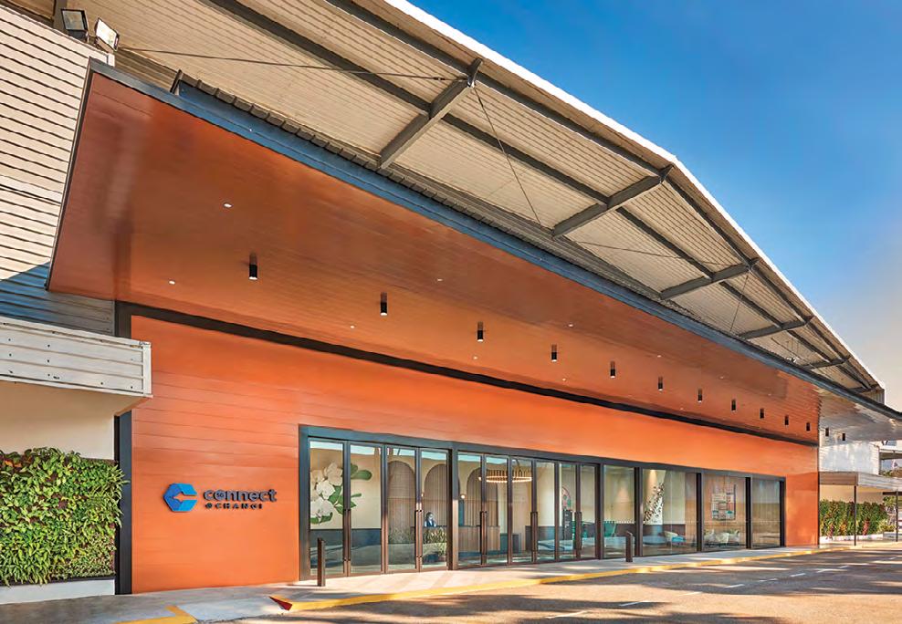
COVER STORY: Enabling safe meetings between international business travellers and Singapore residents

PLUS

CIVIL & STRUCTURAL ENGINEERING: Advantages of the Hat type steel sheet pile method for Earth Retaining and Stabilising Structures DIGITALISATION: Reimagining bridge inspections through the lens of digital twins PROJECT APPLICATION: Clearing the way for a new viaduct on the Budapest-Belgrade high-speed line


Have your competency recognised!


CONTENTS

www.ies.org.sg

FEATURES COVER STORY 14 Enabling safe meetings between international business travellers and Singapore residents Purpose-built facility opens its doors.

CIVIL & STRUCTURAL ENGINEEERING 16 Advantages of the Hat type steel sheet pile method for Earth Retaining and Stabilising Structures Since 2012, this method is being used in many projects in Singapore.

14

21 Design economics of multi-purpose offshore wind farms The conventional development concept and an alternative approach are presented and compared. 28 Reducing seismic risk with strengthening systems based on FRP composites and applied externally only Experimental work has validated the benefits of this innovative approach.

DIGITALISATION 32 Reimagining bridge inspections through the lens of digital twins Advanced technologies can complement standard methods and ensure better outcomes.

PROJECT APPLICATION 34 Clearing the way for a new viaduct on the Budapest-Belgrade high-speed line A number of challenges were addressed and rapid progress was achieved in the construction.

16

REGULAR SECTIONS 02 INDUSTRY NEWS 36 PRODUCTS & SOLUTIONS

32

38 IES UPDATE

President Dr Richard Kwok Chief Editor T Bhaskaran t_b_n8@yahoo.com Publications Manager Desmond Teo desmond@iesnet.org.sg Publications Executive Queek Jiayu jiayu@iesnet.org.sg

Editorial Panel Dr Chandra Segaran Prof Er Meng Joo Dr Ang Keng Been Mr Gary Chiam Dr Victor Sim Mr Syafiq Shahul Dr Alexander Wiegand Media Representative Multimedia Communications (2000) Pte Ltd sales@multimediacomms.sg

Design & layout by 2EZ Asia Pte Ltd Cover designed by Irin Kuah Cover images by Connect@Changi Published by The Institution of Engineers, Singapore 70 Bukit Tinggi Road, Singapore 289758 Tel: 6469 5000 I Fax: 6467 1108 Printed in Singapore

The Singapore Engineer is published monthly by The Institution of Engineers, Singapore (IES). The publication is distributed free-of-charge to IES members and affiliates. Views expressed in this publication do not necessarily reflect those of the Editor or IES. All rights reserved. No part of this magazine shall be reproduced, mechanically or electronically, without the prior consent of IES. Whilst every care is taken to ensure accuracy of the content at press time, IES will not be liable for any discrepancies. Unsolicited contributions are welcome but their inclusion in the magazine is at the discretion of the Editor. THE SINGAPORE ENGINEER March 2021

01


INDUSTRY NEWS

CALL FOR NOMINATIONS FOR THE 2021 GOING DIGITAL

AWARDS IN INFRASTRUCTURE Bentley Systems Incorporated, a leading infrastructure engineering software company, has issued a call for nominations for the 2021 Going Digital Awards in Infrastructure. Formerly known as the Year in Infrastructure Awards, this global awards programme, judged by independent juries of industry experts, recognises infrastructure projects for digital innovations that improve project delivery and/or asset performance. The deadline for nominations is 21 May 2021. The Going Digital Awards are an integral part of Bentley’s annual Year in Infrastructure Conference. The conference brings together infrastructure professionals and industry thought leaders from around the world to share best practices and learn about the latest advances in technology that will improve infrastructure project delivery and asset performance. Winners will be announced during the awards ceremony at the culmination of the conference. Users of Bentley software are invited to nominate their projects for the Going Digital Awards, no matter which phase the project is in - planning/conception, design, construction, or operations. Three finalists chosen for each awards category will get a global platform to present their projects before the judges, industry thought leaders, and media members. Every project nominated for an award receives recognition across the global infrastructure community. Through the Going Digital Awards programme, participants will be able to achieve the following: • Gain global recognition by having their infrastructure projects profiled in Bentley’s Infrastructure Yearbook, which is distributed to media, government, and industry influencers around the world. All winning and finalist projects are also featured on bentley.com. • Enhance their competitive edge by demonstrating to existing and potential clients the value the participants add to projects through their digital innovations. • Receive coverage from global media and support from the Bentley team in marketing and promoting their respective projects to the media. The 2021 Going Digital Awards will recognise outstanding achievements for infrastructure projects and assets in the following categories: Bridges • Buildings and Campuses • Digital Cities • Digital Construction • Geotechnical Engineering • Land and Site Development • Manufacturing • Mining and Offshore Engineering • Power Generation • Project Delivery Information Management • Rail and Transit • Reality Modeling • Roads and Highways • Road and Rail Asset Performance • Structural Engineering • Utilities 02

THE SINGAPORE ENGINEER March 2021

The 2021 Going Digital Awards will be an integral part of Bentley Systems’ 2021 Year in Infrastructure Conference. Image: Bentley Systems.

and Communications • Utilities and Industrial Asset Performance • Water and Wastewater Treatment Plants • Water, Wastewater and Stormwater Networks. Additionally, projects that represent Bentley’s mission of advancing infrastructure, but transcend the narrower focus of the individual category awards, can be considered for Founders’ Awards (formerly known as the Special Recognition Awards). The projects cover, but are not limited to, the following: • Advancements in Digital Twins for Project Delivery (Project Digital Twins) for a project using a digital twin to gain useful insights such as understanding the impact of change and design alternatives or highlighting issues with the quality of project data; to collaborate with the extended project team more effectively; or to model the performance of a project and its construction. • Advancements in Digital Twins for Asset Performance (Performance Digital Twins) for a project involving an operating infrastructure asset that uses a digital twin to gain useful insights to improve the performance in areas such as throughput, safety, compliance, or maintenance; to evaluate the relative impact of different operational strategies; to support training operational staff; or to support remote operations. • Advancements in Sustainability and Resilience for a project that has leveraged digital technology in the design or operations of an infrastructure asset to achieve better sustainability (lower carbon footprint, better use of renewables, reduced environmental impact), higher resilience (ability to withstand and recover from human-made or natural disasters, adaptability to changing conditions), or to deliver social benefits (includes health and safety and community benefits) or improved governance (facilitating and promoting transparency in reporting, compliance, codes of conduct, and risk management). For more information on the 2021 Going Digital Awards programme, or to nominate a project, the Going Digital Awards in Infrastructure website can be accessed.


INDUSTRY NEWS

SINGAPORE’S INTEGRATED TRAIN TESTING CENTRE

TO BE FULLY OPERATIONAL IN 2024 Civil construction of the Land Transport Authority’s (LTA) Integrated Train Testing Centre (ITTC) commenced recently with a groundbreaking ceremony officiated by Minister for Transport, Mr Ong Ye Kung. The ITTC will support the testing and commissioning of trains and railway systems for both new and existing rail lines. For example, the ITTC will support the testing of Circle The Integrated Train Testing Centre (ITTC) will be fully operational by end-2024. Line 6 trains and systems, as well as • A straight high-speed track with minimal curvature and the mid-life upgrades of trains in Singapore. gradient for dynamic speed testing of up to 100 km/h. With a dedicated facility, train testing works can be carried out away from the mainline, round-the-clock, thus freeing up time and space for other maintenance activities to be carried out during the limited engineering hours. In addition, the ITTC’s operations will reduce the need for Early Closure and Late Opening (ECLO) to facilitate train testing, minimising inconvenience to commuters. Occupying a site of approximately 50 hectares, the ITTC will also feature a one-stop workshop for mid-life upgrading and testing of trains before they are deployed on the mainline. With the troubleshooting capabilities available locally at the ITTC, LTA and the operators will be able to speed up the diagnosis and rectification of faults in Singapore and boost ongoing efforts to maintain rail reliability.

Features of the ITTC To facilitate a comprehensive range of testing modules, the ITTC will house three separate types of tracks for specific safety-critical tests: • A looped endurance track with a section that has an uphill gradient for train performance testing. • A looped performance and integration track with a branched ‘S-shaped’ track. 04

THE SINGAPORE ENGINEER March 2021

The ITTC provides a common platform for train testing services. Its test tracks are designed to be interoperable and they can accommodate all types of signalling and communication systems used across the MRT network. It will also be equipped with both third-rail and overhead catenary power systems to allow for concurrent testing of trains and systems from different MRT lines. The ITTC will be designed to achieve the BCA’s Green Mark Platinum certification, with energy-efficient equipment incorporated into its design and operations. These include the use of LED lighting, solar panels and a centralised chiller system. To facilitate seamless connectivity and encourage walking and cycling within the compound, bicycle parking facilities and sheltered linkways which connect to various buildings will be provided. The ITTC is expected to be completed in two phases. The first phase, which includes the construction of the high-speed test track, is targeted to be completed in the fourth quarter of 2022, in time to receive the new Circle Line 6 trains in early 2023. The ITTC will be fully operational by end-2024, with the completion of the two remaining test tracks, the Administration Building, Operations Control Centre Building and workshops.


INDUSTRY NEWS

LTA AWARDS CIVIL CONTRACT FOR THE CROSS ISLAND LINE PHASE 1 The Land Transport Authority (LTA) has awarded the civil contract to design and construct the bored tunnel between Aviation Park Station and Loyang Station (the station names are working names) of the Cross Island Line Phase 1 (CRL1). The contract has been won by Taisei Corporation - China State Construction Engineering Corporation Limited Singapore Branch Joint Venture, at a total contract value of SGD 356 million. Taisei Corporation and China State Construction Engineering Corporation Limited Singapore Branch have established track records in providing design-andbuild construction services which include rail stations and tunnels locally and abroad. Taisei Corporation is currently involved in the construction of Marina Bay Station and tunnels for the Thomson-East Coast Line, while China State Construction Engineering Corporation Limited Singapore Branch is currently working on the construction of Keppel Station and Cantonment Station for Circle Line 6, as well as tunnels for the North East Line Extension. The company had previously completed the construction of Kaki Bukit Station and Geylang Bahru Station for Downtown Line Stage 3 and Canberra Station for the North-South Line. Construction works for the 3.2 km tunnel between Aviation Park Station and Loyang Station is expected to start in the second quarter of 2021. For the first time, LTA will use a large-diameter tunnel boring machine to construct a single tunnel with two tracks in it. CRL1 is slated to commence passenger service in 2030.

The CRL The CRL, Singapore’s eighth MRT line, is the longest fully underground line at more than 50 km in length. It will serve existing and future developments in the eastern, western, and north-eastern corridors, linking major hubs such as Jurong Lake District, Punggol Digital District and Changi region. When fully completed, the CRL is expected to have a daily ridership of at least 600,000 in the initial years, growing to 1,000,000 in the longer term. The CRL will have almost half of its stations as interchanges with other train lines, making it easier and more convenient to travel across the rail network. It will be constructed in three phases. CRL1 is 29 km long and comprises 12 stations from Aviation Park Station to Bright Hill Station (the station names are working names). This will serve residential and industrial areas such as Loyang, Tampines, Pasir Ris, Defu, Hougang, Serangoon North and Ang Mo Kio, and benefit more than 100,000 households. With CRL1,

common recreational spaces such as Changi Beach Park and Bishan-Ang Mo Kio Park will be more accessible by public transport. Studies on the details of subsequent CRL phases are ongoing.

ALSTOM COMPLETES ACQUISITION OF BOMBARDIER TRANSPORTATION In late January 2021, Alstom announced the completion of the acquisition of Bombardier Transportation. According to Alstom, integrating Bombardier Transportation will strengthen its leadership in the growing sustainable mobility market by reaching a critical size in all geographies and integrating further solutions and assets to better serve its customers worldwide. The enlarged group employs 75,000 people worldwide in 70 countries, and has strong R&D capabilities and a complete portfolio of products and solutions.

An increased worldwide reach The group will have a larger commercial reach in all geographies thanks to the complementarities of the two companies. While the Alstom Group already had a well-established customer base in France, Italy, Spain, India, Southeast Asia, Northern Africa and Brazil, Bombardier Transportation will bring strong customer proximity in strategic markets such as the United Kingdom, Germany, the Nordic counries, China, and North America.

A complete portfolio The group will offer products and solutions throughout the entire rail value chain to mobility operators and network providers. By integrating Bombardier Transportation, Alstom will have a complete rail portfolio. In rolling stock, its portfolio will range from light rail to very highspeed trains, including new strategic products such as people movers and monorails. The group will be able to serve its clients in the ‘services’ space with a wider maintenance facilities network and larger predictive maintenance capabilities. With a fleet of 150,000 vehicles, Alstom will have the largest installed base worldwide, a unique springboard to further expand its leadership in services, while its signalling product line will gain significant scale.

THE SINGAPORE ENGINEER March 2021

05


INDUSTRY NEWS

PUB AWARDS INDUSTRIAL LIQUIDS MODULES CONTRACT FOR TUAS WATER RECLAMATION PLANT PUB, Singapore’s National Water Agency, recently appointed China State Construction Engineering Corporation (Singapore Branch) to construct the Industrial Liquids Modules (ILMs) for the Tuas Water Reclamation Plant (WRP), which will treat industrial used water channelled to Tuas WRP via the deep sewer tunnels. The contract, which is valued at SGD 237.6 million, includes the civil, structural and architectural works for two ILMs which will have a treatment capacity of 150,000 m3 per day of industrial used water. Tuas WRP, a key component of PUB’s DTSS Phase 2 project, will be equipped to receive both industrial and domestic used water streams from two separate deep tunnels for treatment. The ILMs will adopt the Membrane Bioreactor (MBR) system, by combining the conventional Modified Ludzack-Ettinger (MLE) process with membranes for solids separation. This integration of membranes enables used water to be treated using less space and fewer steps, compared to conventional systems, in addition to producing a higher quality treated effluent. The treated effluent from the ILMs will be further purified into industrial water and sent back to the industries for reuse. When completed, this will be the first time that PUB is reclaiming industrial used water for reuse, and will be a significant step forward in boosting Singapore’s capability to reclaim and recycle water. China State Construction Engineering’s bid for Tuas WRP’s ILMs was one of 11 offers from an open tender exercise in May 2020. The plant and process equipment (i.e. mechanical, electrical and instrumentation components) will be installed through separate contracts. Construction works on the ILMs was scheduled to commence on 30 December 2020 and the ILMs are expected to be commissioned progressively by December 2025. This is the sixth major Tuas WRP construction contract awarded by PUB. The first was awarded, in January 2019, to McConnell Dowell South East Asia Private Limited to carry out site development works. Koh Brothers Building & Civil Engineering Contractor (Pte) Ltd and China Harbour (Singapore) Engineering Company Pte Ltd Joint Venture (JV) were appointed, in July 2019, to build the Tuas WRP’s Influent Pumping Stations. CES_SDC Pte Ltd (a member of Chip Eng Seng Group) clinched the third contract for the plant’s biosolids treatment facility, in March 2020. In July 2020, Sinohydro Corporation Limited (Singapore Branch) was awarded the contract for the construction of the civil structures of the Domestic Liquids Modules. In October 2020, ABB Pte Ltd was

06

THE SINGAPORE ENGINEER March 2021

appointed to construct Tuas WRP’s Monitoring and Control System. Tuas WRP will have an initial treatment capacity of 800,000 m3 per day. The plant will be co-located with the National Environment Agency's (NEA) Integrated Waste Management Facility (IWMF) to collectively form Tuas Nexus which integrates used water and solid waste treatment processes to harness various synergies that will improve overall plant performance and optimise land use. DTSS Phase 2 is a SGD 6.5 billion infrastructure project that will enhance Singapore's water sustainability by boosting PUB’s capability to reclaim and recycle water in an endless cycle. Upon completion in 2025, DTSS Phase 2 will convey used water from the western part of Singapore to Tuas WRP for treatment. DTSS Phase 1, which covers eastern Singapore and channels used water to Changi WRP, was completed in 2008.

CONSTRUCTION OF TUAS NEXUS BEGINS In early September 2020, the National Environment Agency (NEA) and PUB, Singapore’s National Water Agency, announced that the first phase of construction of Tuas Nexus has begun, and it is set to be completed in phases from 2025 onwards. Collectively known as Tuas Nexus, the integration of the Tuas Water Reclamation Plant (Tuas WRP) and the Integrated Waste Management Facility (IWMF) is an innovative and sustainable solution to meet Singapore’s long-term solid waste management and used water treatment needs. The co-location of two mega facilities - the Tuas WRP and IWMF - will help forge a more sustainable Singapore by optimising land use and maximising energy and resource recovery. The world’s first integrated waste and water treatment facility to be conceptualised and planned from the ground-up, Tuas Nexus will be energy self-sufficient by harnessing synergies from Tuas WRP and IWMF. This is expected to result in carbon savings of more than 200,000 tonnes of CO2 annually. In addition, integrating both facilities will result in land savings of up to 2.6 hectares.


INDUSTRY NEWS

SNC-LAVALIN POSITIONS FOR GROWTH IN ENGINEERING SERVICES SNC-Lavalin Group Inc recently announced the appointment of Mr Steve Morriss, a seasoned engineering services executive, as the new President for Asia Pacific and Middle East. Mr Morriss will lead engineering services in these regions, unifying Mr Steve Morriss and consolidating existing operating businesses, and will report directly to the President and CEO. He will also be a member of the Executive Committee. Mr. Morriss brings a wealth of experience and global expertise that will enhance SNC-Lavalin’s growth capabilities in various markets. He was Group President, Design and Consulting Services, Americas at AECOM, where he led

the group’s technical services business that had more than 20,000 employees across the United States, Canada and Latin America. The activities of the business include master planning, design, environmental planning, cost management, engineering, and project management for a range of market sectors including transportation, water, defence, power and energy, sports and leisure, education and healthcare. SNC-Lavalin has a strong presence in the Asia Pacific and Middle East regions. Its portfolio of marquee projects in these regions include the Landmark 81 building in Ho Chi Minh City, Vietnam, named one of the World's top 10 Skyscrapers in 2019; the Riyadh Metro, Riyadh, Saudi Arabia; and the Dubai Opera, Dubai. Last October, the company was awarded the lead design consultant services contract for the Six Flags Qiddiya theme park outside Riyadh.

THE SINGAPORE ENGINEER March 2021

07


INDUSTRY NEWS

LENDLEASE REINFORCES DIGITAL BUSINESS BENCH STRENGTH WITH

TWO SENIOR LEADERSHIP APPOINTMENTS Lendlease, a leading international property and infrastructure group with operations in Australia, Asia, Europe and the Americas, has Mr Richard Mr Preetham announced two Nadig strategic leadership Kuppusamy appointments at its digital arm, Lendlease Digital, to continue its commitment to the digital transformation of the property and construction sectors.

achieved, as we strive towards the development of a more sustainable, healthy world”, said Mr Kuppusamy. Lendlease has also appointed Mr Preetham Nadig as the Head of its Singapore Product Development Centre and the Vice President of Engineering for Lendlease Digital, Asia. In his new role, Mr Nadig will be responsible for driving Lendlease Podium’s product technology roadmap and the development of digital solutions for the built environment. He reports to Mr Pankaj Srivastava, Chief Technology Officer, Lendlease Digital.

Mr Richard Kuppusamy has assumed the role of the Head of Lendlease Digital, Asia, effective since September 2020. He retains his role as the Head of Digital Engineering for Integrated Solutions, Asia, which he has held since February 2019. He assumes leadership in the management and performance of the digital business unit in the region.

“We are delighted to have Preetham on board to lead the strategic vision in Singapore’s Product Delivery Centre. With his leadership, the team will deliver first-to-market digital solutions that cut across design, construction and global property supply chains. With Preetham added to our team of innovators and digital experts, we are confident that Lendlease Digital is wellpositioned to propel the built world into the digital age”, Mr Srivastava said.

“I am excited to be working with a team of innovators that are breaking down boundaries in the physical world and revolutionising the places we create and the way in which we build. As a team, we look forward to driving new breakthroughs in the digitalisation of the built environment, the emergence of autonomous buildings, and leveraging the momentum we have already

Mr Nadig brings with him over 18 years of experience in leading delivery teams in tech startups and mature platforms, in areas such as blockchain, telehealth, e-commerce and supply chain. Most recently, he led the Digital Products team at Zuellig Pharma and has previously held leading roles in companies across the pharmaceutical, consumer goods and automotive sectors.

LENDLEASE INCLUDED IN WORLD’S TOP 10 INNOVATIVE COMPANIES LIST A dedication to innovation, coupled with a commitment to sustainability and the adoption of digital technologies, has resulted in Lendlease being ranked by Fast Company as one of the world’s most innovative companies. Lendlease is ranked 9th in the Urban Development category on the 2021 Most Innovative Companies list. Fast Company is a global media brand with a focus on innovation in technology, leadership and design. Each year, it honours those companies making a profound impact in the sectors in which they operate. Previous recipients of the honour include Microsoft, Walt Disney Company, and Apple. Lendlease’s mission is to create places that leave a positive legacy with a focus on health, innovation and sustainability. In recent years, the company achieved three world firsts and three Australian firsts in sustainability, for creating the following: • The world’s largest collection of healthy workplaces in one portfolio • The world’s largest collection of sustainable Senior Homes

08

THE SINGAPORE ENGINEER March 2021

• World’s most sustainable real estate fund - for the fifth time (APPF Commercial) • Australia’s first carbon-neutral construction service • Australia’s first carbon-neutral precinct (Barangaroo, New South Wales) • Australia’s most sustainable community (Alkimos Beach, Western Australia) Lendlease continues to build on this success. In July 2020, it launched Lendlease Podium, a property lifecycle platform that aims to provide insights and clarity from data capture which, the company says, is unlike anything the property and construction industry has seen before. Harnessing technology like Podium means Lendlease will be able to optimise its choice of partners, suppliers and sustainable materials, creating less material waste and choosing and harnessing renewable energy sources. Identifying and partnering with green suppliers further enables Lendlease to accelerate its innovation footprint and progress on its commitment to be a 1.5°-aligned company.


INDUSTRY NEWS

PAN-UNITED ACHIEVES SINGAPORE’S LARGEST TWO CONTINUOUS CONCRETE POURS WITHIN A MONTH Concrete innovation company Pan-United Corporation Ltd achieved Singapore’s largest two continuous readymix concrete pours while casting the raft foundation for a development project in the Labrador area. The group’s subsidiary, Pan-United Concrete, set a national record when it poured 18,916 m3 for 57 hours non-stop, from 31 October to 2 November 2020. This first pour was followed by a second pour of 18,342 m3 of concrete in a shorter time of 42 hours non-stop, from 27 to 29 November 2020, to complete the raft foundation. The mixer truck convoys delivered one truckload of concrete non-stop every 60 seconds. The total concrete volume of the two pours, at 37,258 m3, is equivalent to filling 14 Olympic-sized swimming pools. The previous record of 18,000 m3 was set in March 2015, for the Marina One raft foundation. Ready-mix concrete is produced just-in-time and typically has a brief two-hour workable lifespan. Pan-United designed a special concrete that remained workable for six hours, to ensure the layers bonded integrally to form a solid raft. The complex logistics planning for the production, delivery and casting of the raft foundation, stretching over several months, was conducted in close collaboration with Hyundai Engineering & Construction (Hyundai), the main contractor for the development. Mr Ken Loh, Chief Operating Officer of Pan-United, said, “We are thankful to Hyundai for taking all the measures necessary to ensure safe distancing and to greatly reduce any health risks to the teams handling the massive pours. Pan-United also used our contactless processes such as e-delivery orders, e-concrete sampling, e-sign-offs, and our customer portal to minimise physical interaction at the worksite”.

United will continue to innovate concrete and logistics solutions that can address any complex challenge in building smart cities like Singapore”, Mr Loh continued. AiR is the acronym for Artificial Intelligence for ReadyMix Concrete. Mr Chan Wai Mun, Operations Director of Pan-United Concrete, said, “Technology-enabled precision was absolutely crucial in both mass pours to ensure zero disruptions to concrete placement. The continuous supply allows the concrete raft foundation to set uniformly within the required temperature properties”. Highlighting the sustainable aspects of the massive operation, Mr Chan added, “A sustainable Grade 55 temperature-controlled flowing concrete (PanU Cool) was chosen to improve the structural integrity and durability of the raft foundation. Chiller systems developed in-house were used to maintain the low heat of this special flowing concrete so as to prevent cracking during the setting of the huge raft”. “Our custom concrete ‘recipe’ for PanU Cool comprised sustainable raw materials, such as ground granulated blast furnace slag, a by-product of steel production. We also used silica fume, a by-product of silicon wafer production. Stringent durability requirements were designed to ensure the concrete met high performance criteria such as strength and water-tightness. Virtual quality testing was conducted remotely, using e-sampling to ensure safe distancing”, he continued.

“Both mass pours went very smoothly, thanks to the excellent co-operation with Hyundai, and the tremendous team effort of all parties involved. We had full confidence of success in executing this feat, supported by our concrete innovation specialists and with the advanced logistics managed through our digital optimisation platform called AiR”, he added. “AiR optimises our supply chain, managing the efficiency of our batching plants and ensuring a seamless relay of trucks delivering the concrete. Pan-

Pan-United delivered a total of 37,258 m3 of concrete in two continuous mass pours. THE SINGAPORE ENGINEER March 2021

09


INDUSTRY NEWS

SINGAPORE COMPANY AND JOINT-VENTURE PARTNER WIN

WASTE COLLECTION AND TRANSPORTATION CONTRACT IN CAMBODIA 800 Super, a Singapore company, and its joint-venture partner in Cambodia, GAEA Waste Management, were awarded the contract for waste collection and transportation for one of the three zones in Phnom Penh City by the Phnom Penh Capital Administration. The 800 Super-GAEA joint-venture was selected from a group of over 20 bidders who participated in the tender that the Phnom Penh Capital Administration launched in March 2020. Under the 10-year contract, the joint-venture will be responsible for the collection and transportation of solid waste from five sub-zones in Zone 1 of Phnom Penh City to a transfer station, and ultimately to the regional landfill for Phnom Penh and its surrounding provinces. The estimated waste quantity is around 1,040 tonnes per day in 2020, which is projected to increase to around 2,700 tonnes per day by 2030 as the city grows. 800 Super is one of the three licensed public waste collectors in Singapore, appointed by Singapore’s National Environment Agency (NEA), while GAEA is a Cambodiabased waste collection company, operating in Siem Reap, Kampong Thom, Bantay Meanchey and Kampot provinces. Specialising in waste and recyclables collection, 800 Super incorporates technology in its operations in Singapore to improve productivity and increase efficiency, with support from Enterprise Singapore (ESG). An example is the use of real-time operation monitoring powered by RFID tags on trucks and bins, that ensures that trucks are efficiently performing their duties and bins are properly emptied. Such technologies, including those developed by Singapore start-ups, will also be incorporated throughout the contract’s tenure to support the long-term needs of Cambodia’s growing urban centres. For a start, 800 Super will be introducing the GPS fleet management system that it currently uses in Singapore to better track and manage its assets and enhance its workers’ safety in Phnom Penh City. Combined with GAEA’s local experience, 800 Super is confident that the joint-venture would deliver satisfactory waste collection and transportation service for the residents in Phnom Penh. ESG, NEA and Infrastructure Asia had worked together to share with the Cambodian authorities about Singapore’s solid waste management experience, and the best practices Singapore waste management companies adopt, that ensure sustainable waste management.

10

THE SINGAPORE ENGINEER March 2021

Mr William Lee, Chief Executive Officer of 800 Super, said, “We are delighted to be awarded the contract and are pleased to have GAEA as our partner in this journey. We also thank Enterprise Singapore, National Environment Agency and Infrastructure Asia for their support in our growth and regionalisation journey. The 800 Super-GAEA joint-venture will bring in our collective experience and expertise in working with the Phnom Penh Capital Administration to enhance Phnom Penh’s cleanliness and liveability. We will also continue to explore new opportunities in Cambodia, a very important market in our growth strategy”. Mr Ng Chun Pin, Deputy Chief Executive Officer (Planning, Corporate and Technology) of National Environment Agency, Singapore, said, “This contract is a significant milestone for Singapore’s Environmental Services (ES) sector, and a strong affirmation of the close collaborations between agencies to help our ES companies internationalise. It is also a nod to the capabilities and gumption of our homegrown ES companies, such as 800 Super, who are able to bring value not only through their expertise and experience, but also the integration of technology and innovation to make their services more productive and efficient. We hope this success will spur more ES companies on, and to consider venturing abroad, thereby generating more job opportunities for Singaporeans, both locally and overseas”. Ms Eunice Koh, Assistant Chief Executive Officer of Enterprise Singapore, said, “Despite uncertain times, Singapore companies that have invested in technology continue to forge partnerships overseas and press on with their internationalisation plans. It is also heartening to know that 800 Super, a Singapore company, will be contributing to Phnom Penh City’s public health agenda, a top-of-mind issue for both the government and citizens in current times”. Mr Seth Tan, Executive Director of Infrastructure Asia, said “With increasing urbanisation, waste management is an issue that many cities in the region, including Phnom Penh, are facing. We are glad to know that the Royal Government of Cambodia is taking active steps to optimise its waste sector to support Phnom Penh’s continuing growth. This is also an area to which Singapore-based players such as 800 Super are well-placed to contribute, given their experience and expertise in municipal waste management”.


INDUSTRY NEWS

WORKPLACE INJURY RATE RETURNS TO PRE-COVID LEVELS IN LATE 2020 According to the Workplace Safety and Health Report 2020, released by the Ministry of Manpower (MOM), the total number of workplace injuries for 2020 fell by 18%, from 13,779 in 2019 to 11,350 in 2020, while workplace fatalities reduced from 39 in 2019 to 30 in 2020. This translates to a workplace fatal injury rate of 0.9 per 100,000 workers. The fewer injuries were due largely to the suspension of workplace activities in the second and third quarters of 2020, to manage the COVID-19 outbreak. However, the number of workplace injuries reverted to pre-COVID levels by the fourth quarter of 2020, with 3,413 workplace injuries reported, compared to 3,445 in the same quarter in 2019.

Fatal injuries Falls from height continued to be the top contributor to workplace fatalities, with eight cases in 2020, compared to seven in 2019. Vehicular incidents accounted for four cases in 2020, compared to seven in 2019. Together, they contributed to 40% of all fatal workplace accidents last year.

Major and minor injuries Slips, Trips and Falls (STF) and Machinery Incidents remained the leading causes of non-fatal injuries, contributing to nearly half of all major injuries last year. However, the number of incidents has decreased significantly due to COVID-related work stoppages. There were 159 STF major injuries in 2020, down from 216 in 2019; and 3,318 STF minor injuries, down from 3,694 in 2019. Machinery Incidents accounted for 58 major injuries in 2020 compared to 82 in 2019; and 1,696 minor injuries compared to 2,178 in 2019.

Injuries by industry Construction and Manufacturing made up for half of all workplace fatalities last year. Construction continued to account for the highest number of fatalities, although it decreased significantly, with nine cases in 2020 compared to 13 in 2019. The fatal injury rate also fell from 2.9 per 100,000 workers in 2019 to 2.2 per 100,000 workers in 2020. This was likely due to work stoppages in the second and third quarters of 2020. However, closer attention should be paid to the Manufacturing sector, which saw six fatalities in 2020, compared to four in 2019. Its fatal injury rate increased from 1.0 per 100,000 workers in 2019 to 1.5 per 100,000 workers in 2020. In addition, Manufacturing was also the top contributor of non-fatal injuries last year, with 110 major and 2,330 minor injuries.

Dangerous occurrences The number of dangerous occurrences (DOs) was halved, from 21 in 2019 to 10 in 2020. This was likely due to work stoppages, especially in the construction sector. Seven cases were caused by collapse/failure of structures, and the other three were fires and explosion. DOs are incidents with a high potential for multiple fatalities.

Occupational diseases The number of Occupational Diseases (ODs) increased slightly by 2%, from 517 cases in 2019 to 528 in 2020. This was partly contributed by 34 COVID-19 cases, classified as work-related. The top three ODs were work-related musculoskeletal disorders (WRMSD), noise-induced deafness (NID), and infectious diseases which, in total, accounted for 89% (472) of all OD cases in 2020.

Stop-Work Orders and fines since December 2020 The escalating injury rate in late 2020 and the spate of accidents in February 2021 are a cause for concern. Companies could be rushing to catch up on project delays, following work stoppages, with the situation exacerbated by manpower disruptions due to the pandemic. MOM urges companies not to neglect WSH while balancing project schedules and manpower constraints. Companies should refresh workers’ WSH training and review risk assessments, especially if there have been changes to their work processes or workplace, due to COVID-19. To reinforce this message, between mid-December 2020 to mid-March 2021, MOM mounted more than 1,000 inspections under Ops ROBIN, targeting high risk industries and found contraventions in 55% of workplaces inspected. MOM issued a total of 13 Stop-Work Orders, 264 composition fines amounting to SGD 303,000 and 1,270 Notices of Non-Compliance. The top contraventions uncovered include fall from height risks, and poor maintenance of heavy machinery such as excavators, boom lifts and forklifts. Following the fatal Tuas explosion on 24 February 2021, that killed three and injured another seven workers, MOM convened an Inquiry Committee (IC) to look into the causes and circumstances that led to the accident. Before the findings are made known, MOM has also stepped up inspections, launching Ops BULLFINCH 2, which targeted 500 companies working with combustible dust that could pose similar risks. Around half of them have been inspected so far. Most companies inspected generated small quantities of dust with low explosion risk. However, three companies were found to have inadequate control measures despite significant risk of combustible dust explosions and were issued Stop-Work Orders. THE SINGAPORE ENGINEER March 2021

11


INDUSTRY NEWS

In the meantime, it is also in the interest of companies to have adequate safety measures in place. The consequence of a combustible dust explosion can be severe. Hence, MOM urges all companies with operations involving combustible dust to undertake a review of their control measures.

Focusing on STFs Beyond enforcement operations on higher-risk workplaces, MOM continues to be concerned about Slips, Trips and Falls (STFs), which were prevalent in the cleaning, transport, F&B and security industries. This is especially pertinent for an ageing workforce where STFs may result in a more serious injury. MOM and the WSH Council will be engaging these industries to improve their WSH training and to better educate them on STF prevention. The WSH Council will also launch a campaign in June to encourage companies to prevent STFs and create greater awareness among all workers.

Together with Infocomm Media Development Authority (IMDA) and Building and Construction Authority (BCA), MOM is working with a technology firm and industry partners to develop a solution to prevent STFs. A prototype was developed through the Built Environment Accelerate to Market Programme: Digital (BEAMP: D) on Open Innovation Platform (OIP) to detect STF incidents, near misses and hazards using video analytics and wearables. The prototype has been test-bedded with industry partners and is currently ready to market for use by industry. Commissioner for Workplace Safety and Health and Divisional Director of MOM’s Occupational Safety and Health Division, Mr Silas Sng, said, “The commitment of a company’s leadership is key to preventing accidents. They should not wait for inspectors to pick up lapses, but should instead proactively take steps to assess the risk of their operations and take adequate control measures to prevent accidents from occurring”.

STF TECHNOLOGY SOLUTIONS The Workplace Safety and Health Institute (WSHI), Ministry of Manpower, launched an industry challenge in April 2020 on the Built Environment Accelerate to Market Programme : Digital (BEAMP : D) on Open Innovation Platform (OIP) to seek innovative technology solutions to detect STF near misses and hazards. The project was in collaboration with IMDA and BCA. Vulcan AI Pte Ltd (Vulcan AI), a local deep-tech startup specialising in AI solutions to improve safety and productivity, was awarded the challenge to develop the STF technology solution. The technology using video analytics, enables STF incidents, near misses and hazards to be detected realtime via CCTV feeds. For areas not covered by CCTVs, workers can be equipped with wearables. When an STF incident or near miss occurs, the supervisor receives a real-time alert (with video feed) via a mobile app for prompt intervention. The detection of near misses also allows STF hot spots to be identified for hazard removal or increased frequency of housekeeping. In addition, the solution provides an audit trail for incident reporting and resolution. Insights such as the top STF hazards as well as the frequency of near misses and hot spots, can be generated via the analytics dashboard. The test-bedding of the solution with industry partners has shown good results. Both the video analytics and wearables components are able to achieve a high accuracy of detection of STF incidents and near misses. Version One of the technology is now ready to market. Drawing from industry feedback, the technology will be further enhanced by Vulcan AI with improved features

12

THE SINGAPORE ENGINEER March 2021

such as scaling the dashboard to enable monitoring of multiple sites.

Key Benefits • Detects STF near misses which allows early interventions such as hazard removal or correction of workers’ risky behaviour. • Improves response time to an STF incident. • Automates the generation and digital storage of STF incident reports. • Provides audit trail on resolution of an STF incident, near miss or hazard. • Dashboard for businesses to monitor and analyse WSH performance.

BEAMP : D The Built Environment Accelerate to Market Programme (BEAMP) was set up to bring inventors and companies together to fast-track the innovation process to solve real-world industry challenges. This programme was launched by BCA, JTC Corporation (JTC) and Enterprise Singapore (ESG) in February 2019. BEAMP : Digital (BEAMP : D) is a call for digital-centric innovations in the Built Environment sector that leverages IMDA’s Open Innovation Platform (OIP). Innovators that have successfully completed their project under BEAMP : D have the chance to apply under the Market Development phase of BEAMP to further develop and validate the solutions in the market.


INDUSTRY NEWS

January – December 2020

SINGAPORE WORKPLACE SAFETY & HEALTH REPORT Fewer workplace injuries in 2020 due to work stoppages. Fatal Injuries

50

66

0

2016

2.0

1.2

1.2

1.1

42

41

39

30

2017

2018

2019

2020

1.0

0

2016

376

355

2017

0

329

2018

2019

16.9

17.4

18.1

594

574

596

629

2016

2017

2018

2019

Occupational Disease Incidence

400

1200

200

600 0

0

2020

17.4

21.5

23.6

732 2016

20.0

14.0

10.0

463

0.0

2020

No. of Occupational Diseases Occupational Disease Rate Per 100,000 Workers

16.4

14.8

16.0

799

563

517

528

2017

2018

2019

2020

30.0 15.0 0.0

Fewer fatal and major injuries in various industries, including Construction, Transportation & Storage, and Accommodation & Food Services industries in 2020. Exception was more fatal injuries in Manufacturing. ii. Fatal and Major Injuries for Construction, Construction remained theincreased top contributor to fatal injuries. and reduced for

Major Injuries Fatal Injuries

Manufacturing and Transport & Storage in 1Q 2018

7

24

4

4

14

12

6

Accommodation & Food Services

Transportation & Storage

Construction

Manufacturing 9

500

0.0

12,354 11,882 12,173 13,111 10,857

7,500

1000

Workplace Minor Injury Rate Per 100,000 Workers

350

363

0.9

No. of Minor Injuries

Minor Injuries

15,000

Workplace Major Injury Rate Per 100,000 Workers

Workplace Fatal Injury Rate Per 100,000 Workers

1.9

100

No. of Major Injuries

Major Injuries

No. of Fatal Injuries

13 9

11

7 4

8

5

2 0

1

130

136

134

143

110

167

129

147

135

74

51

74

52

62

50

45

45

40

65

50

2016

2017

2018

2019

2020

2016

2017

2018

2019

2020

2016

2017

2018

2019

2020

2016

2017

2018

2019

2020

Falls from Height remained the top cause in fatal injuries in 2020; Slips, Trips & Falls continued as top cause of major injuries.

4

7

3

Major Injuries Fatal Injuries

Vehicular Incidents

Falls from Height

Machinery Incidents

Slips, Trips & Falls 6

0

0

3 3

1

1

2

2

13

8

8

7

8

22

14

7

7

4

41

46

41

36

2017

2018

2019

2020

173

177

203

216

159

86

74

76

82

58

73

63

71

62

51

50

2016

2017

2018

2019

2020

2016

2017

2018

2019

2020

2016

2017

2018

2019

2020

2016

Note: [1] The breakdown for injury numbers by sector/industry follows the Singapore Standard Industrial Classification (2015) Version 2018

[2]

Refer to Workplace Safety and Health Report 2020 for more detailed information

THE SINGAPORE ENGINEER March 2021

13


COVER STORY

ENABLING SAFE MEETINGS BETWEEN INTERNATIONAL BUSINESS

TRAVELLERS AND SINGAPORE RESIDENTS Purpose-built facility opens its doors. Temasek recently announced the launch of the first phase of Connect@Changi, a pilot short-stay facility designed to support safe business exchanges between international business travellers and Singapore residents.

Located at Singapore EXPO & Max Atria, within a five-minute drive from Changi Airport, Connect@Changi offers an integrated ‘test-stay-work-meet’ experience for inbound business travellers.

As the first facility appointed under the Connect@Singapore initiative, Connect@Changi aims to support the progressive reopening of the nation’s borders and spur business and economic activities, while safeguarding the local community from the COVID-19 pandemic.

Business executives landing at Changi Airport can meet their Singapore-based counterparts or hold regional meetings in person at the facility, all the while enjoying a comfortable stay with an array of safe management measures in place.

Connect@Changi is launching with 150 premium guest rooms and 40 meeting rooms in a range of sizes, that can accommodate from four to 22 attendees. This will expand to around 660 guest rooms and 170 meeting rooms, when the initial phase of the project is completed in May. When fully completed later this year, the facility will have a potential capacity to host some 1,300 business travellers at any one time. When meeting at Connect@Changi, guests will be grouped in cohorts of five. To maintain safe distancing, the use of dividers is being explored, to keep guests in their respective cohorts.

The project is developed by a Singapore consortium, led by Temasek and includes The Ascott Limited, Changi Airport Group, Sheares Healthcare Group, SingEx-Sphere Holdings and Surbana Jurong. “We are thankful for the Singapore Government’s strong support and commitment to the Connect@Changi project, by appointing it as the first facility licensed to operate under the Connect@Singapore initiative”, said Mr Robin Hu, Head of International Policy & Governance, Temasek and Chairman, SingEx-Sphere Holdings. “Without such a facility, travel options are essentially binary - either stay at home due to travel restrictions,

Connect@Changi is developed by a Singapore consortium led by Temasek and includes The Ascott Limited, Changi Airport Group, Sheares Healthcare Group, SingEx-Sphere Holdings and Surbana Jurong. 14

THE SINGAPORE ENGINEER March 2021


COVER STORY

or fly overseas and endure long periods in quarantine. After close to four months of intense, round-the-clock construction and collaboration with our partners, various government agencies, vendors and subcontractors, we are now ready to offer business travellers the option of resuming in-person meetings in a safe and contained manner, and do our part to catalyse economic recovery for Singapore and across the region”, he added. The specially designed meeting rooms are fitted out with air-tight glass panels, to reduce the risk of transmission. Large-scale video conferences can also be held, which would allow hybrid meetings to take place. To ensure the health and safety of guests and employees, all foreign travellers checking into Connect@Changi would be required to go through a rigorous COVID-19 testing regime throughout their stay. This includes a Polymerase Chain Reaction (PCR) Test upon arrival at Changi Airport, on days 3, 7 and 14 of their stay, as well as prior to departing the facility, depending on the requirements of the destination country. Registration and check-in can be done via the Connect@ Changi mobile application before their arrival at the facility, to minimise contact with front desk staff. Singapore-based visitors are not required to undergo testing when accessing the facility, as foreign travellers and local visitors have completely separate entrances, exits and ventilation systems. Advanced MedTech Holdings, a global medical technology leader with a core focus in urology devices and services, will be one of the first companies to conduct business activities

at Connect@Changi. The Singapore-headquartered firm plans to hold its first in-person global senior leadership meeting of up to 30 business executives at the facility - its first since the pandemic began early last year. Said Mr Lee Weikang, Senior Director, Business Development at Advanced MedTech, “In-person meetings allow us to connect tangibly and renew our bonds for a globally-diverse team. The smiles on each other’s faces, the passion in our demeanours, the steely determination etched in our eyes, even the energy emanating from our physical presence - all these are hard to experience over virtual meetings. We are looking forward to our physical meetings at Connect@Changi”. All guests residing at the facility can look forward to a comfortable, fuss-free accommodation of 19 m2, with high-speed wireless internet access (WiFi) for all business and entertainment needs, and access to recreational areas in two courtyards designed with park-like settings. Additionally, Connect@Changi will deploy innovative solutions to minimise contact between guests and frontline staff, such as self-service meeting rooms. Meals will be delivered to pre-installed shelves located outside guest rooms. Guests can also opt for additional F&B options and access other amenities like on-line shopping, and book a slot at The Gym Pod. All images by Connect@Changi

Landside Reception

Airside Reception

The Board Room

Executive Premier King Room

Safe, pleasant and comfortable facilities within Connect@Changi. THE SINGAPORE ENGINEER March 2021

15


CIVIL & STRUCTURAL ENGINEERING

ADVANTAGES OF THE HAT TYPE STEEL SHEET PILE METHOD FOR EARTH RETAINING AND STABILISING STRUCTURES by Masaya Higuchi, General Manager, Nippon Steel Southeast Asia; Takashi Suzuki, Senior Manager, Nippon Steel Southeast Asia; and Ma. Charisse Macaraeg, Civil Engineer, Nippon Steel Southeast Asia

Mr Masaya Higuchi

Mr Takashi Suzuki

Ms Ma. Charisse Macaraeg

The Hat type sheet pile, as an innovative product in ERSS, was developed in Japan in 2005 and has been applied also overseas. Since 2012, it has been used in Singapore when it was described in the BCA design guide as JIS A 5523 grade. Since then, it was gradually used in many projects until now. The Hat type sheet pile has many advantages, like its 900 mm width which is greater than the 400 mm width of the conventional U type sheet pile. So, the number of required sheet piles could be reduced, thus, reducing the total piling length and wall weight, which contribute to the improvement of construction productivity. In the city areas or narrow spaces near residential areas, low noise and low vibration are important. Thus, the Hat type silent piler can be used to achieve this. In this article, we introduce the outlines, advantages, and applicability of the Hat type sheet pile, for optimising the design and construction for future development projects in Singapore. INTRODUCTION

HAT TYPE STEEL SHEET PILE

In recent years, it has been noticed that the construction industry in Singapore is very busy, with projects such as the expansion of airport terminals, new MRT stations, upgrading of water treatment plants, improvement of drainage canals, construction of mixed used-facilities and residential buildings, and many more projects. For these kinds of projects and other similar ones that involve earth retaining works, for example, revetments, quay walls, bridge abutments, and so on, the steel sheet pile is one type of earth retaining wall that is commonly used.

The Hat type sheet pile is considered as the widest hotrolled monolithic pile in the world, because of its 900 mm width per pile. It comprises four types, from NS-SP-10H to 50H, as shown in Figure 1, where the numbers represent the moment of inertia of the pile. Because of its 900 mm effective width, use of the Hat type can reduce the number of sheet piles, thus achieving rapid construction. Also, the Hat type has a higher water-tightness performance due to its lower number of interlocking connections (Picture.1). This is very important in areas with high water levels.

Dimension Effective width

Effective height

Thickness

Sectional area

Moment of inertia

Section modulus

Unit mass

(mm)

(mm)

(mm)

(cm2)

(cm4)

(cm3)

(kg/m)

NS-SP-10H

900

230

10.8

122.2

10500

902

96

NS-SP-25H

900

300

13.2

160.4

24400

1610

126

NS-SP-45H

900

368

15.0

207.8

45000

2450

163

NS-SP-50H

900

370

17.0

236.3

51100

2760

186

Type

Figure 1: Hat type sheet piles and its four sizes. 16

THE SINGAPORE ENGINEER March 2021

Properties per meter of wall


CIVIL & STRUCTURAL ENGINEERING

In the case of the Hat type wall, its interlocks are located on the outermost edge of the wall (Figure 2). The location of these interlocks corresponds to a small shear stress zone, whereas that for a U type wall corresponds to a large shear stress zone (Figure 3).

ERSS DESIGN BY EUROCODE (REDUCTION FACTOR) Since 2015, Singapore has started to adopt Eurocode in the design Picture 1: Track record for cofferdam on the seaside. Image: Steadfast Engineering & Construction Pte Ltd. of ERSS. In Eurocode 3: Part 5 Piling, it is mentioned that the reduction factor must be considered when designing the U type wall (Table 1). On the other hand, the flexural stiffness of the Hat type wall is not reduced because there is sufficient shear force transmission within the Hat’s interlocks. The reduction factor of 1.0 can be used in the design of the Hat type wall, which indicates that the full (100%) sectional performance of the Hat type can be used (Figure 3). By considering this reduction factor in the design, the Hat type becomes more advantageous in terms of steel weight, because it is around 35% lighter than the conventional U type sheet pile (Figure 4). In parallel, the use of the Hat type could also help to improve the construction productivity due to the Hat type’s wider coverage (900 mm) per installed pile, and the costeffectiveness of the projects.

Figure 2: Layout of the Hat type and U type sheet piles as a wall.

CONSTRUCTION PRODUCTIVITY Because of the current pandemic, most of the engineers aim for innovation in construction that is cost-effective and can improve the construction productivity of the project. The COVID-19 has already resulted in major delays or even postponement of some projects, thus, many workers have lost their jobs and many companies have lost income during this season. And due to the situation, solutions that can increase productivity of the projects are sought and recommended in Singapore, thus benefitting the contractor in terms of cost and time savings (Figure 5).

Figure 3: Positional relationship between the interlock of two piles and the shear force distribution on pile walls.

OPTIMISATION IN DESIGN High structural reliability is achievable with the Hat type since its reduction factor in the design is 1.0. In some cases, there is a possibility to reduce the number of temporary supporting systems when using the Hat type, because of its high stiffness property (Figure.6). As per Table 2, using the Hat 45H and 50H can achieve significantly higher stiffness than FSP-IV. In cases where even the use of the Hat 50H cannot satisfy the required stiffness of the wall, it is possible to attach a steel plate to the Hat 50H to increase its stiffness.

Figure 4: Comparison between the Hat type and the U type.

Project Productivity =

Total constructed floor area (m2) Total number of site workers (mandays)

Figure 5: BCA’s formula for Project Productivity. THE SINGAPORE ENGINEER March 2021

17


CIVIL & STRUCTURAL ENGINEERING

Type of U-pile unit

Singles or uncrimped doubles

Crimped or welded doubles

Number of structural support levels (see Note 1)

Reduction factors βa and βo referred to in 5.2.2 (2); 5.2.2 (9); 5.2.3 (2); 6.4 (3) (see Notes 2,3,4 and 5) Highly unfavourable conditions (see Note 6)

Unfavourable conditions (see Note 7)

Favourable conditions (see Note 8)

βa

βo

βa

βo

βa

βo

0

0.40

0.30

0.50

0.35

0.60

0.40

1

0.55

0.35

0.60

0.40

0.70

0.45

>1

0.65

0.45

0.70

0.50

0.80

0.55

0

0.70

0.60

0.75

0.65

0.80

0.70

1

0.80

0.70

0.85

0.75

0.95

0.80

>1

0.90

0.80

0.95

0.85

1.00

0.90

Table 1: Reduction factor in the U type as per SS EN1993-5.

From FSP-IV with 1 strut and 1 king post

To Hat 45H/50H cantilevered wall

From 2 struts

Figure 6: Example of the reduction in the temporary supporting system. 18

THE SINGAPORE ENGINEER March 2021

To 1 strut


CIVIL & STRUCTURAL ENGINEERING

ENVIRONMENTAL CONSIDERATIONS When using Hat type solutions, it is possible to minimise the problems on the site, due to the different construction methodologies involved in their use.

The Hat type sheet pile can also be extracted. This will allow future land development works. The extracted Hat type sheet pile can be reused repeatedly in other projects, to minimise project cost.

The conventional vibratory hammer can be used to drive the Hat type into the ground in normal site conditions (Pictures 2, 3 and 4). While in the city area, where there is congestion due to buildings built close to one another, and in residential areas, as well, it is possible to install the Hat type using the Hat type silent piler, as this method generates low noise and low vibration during piling. This method can prevent damage to nearby structures and can avoid disruption to people living the construction site (Figure 7 and Picture 5). Also, in areas with narrow spaces, it is advantageous to use the Hat type as ERSS, because it has a smaller effective height than that of the conventional FSP-IV. So, it is possible to reduce the wall thickness. This is an essential consideration in areas with very strict space restrictions (Figure 8). Sheet Piles

Moment of Inertia, MOI (cm4/ m)

Stiffness, EI (kNm2/ m)

FSP-IV (reduction factor considered)

15,440

32,400

Hat 45H

45,000

94,500

Hat 50H

51,000

107,300

Hat 50H with steel plates

51,000 - 70,000

110,000 - 150,000

Table 2: Comparison of the stiffness of the Hat 45H and Hat 50H with that of the FSP-IV.

Picture 3: Application in Malaysia as temporary wall (top) and as river revetment (bottom).

Picture 2: Application as a road retaining wall in Australia.

Picture 4: Example of application in a wharf in Indonesia. THE SINGAPORE ENGINEER March 2021

19


CIVIL & STRUCTURAL ENGINEERING

CONCLUSION By taking advantage of the Hat type sheet pile, we can achieve the improvement in construction productivity in Singapore. Especially, according to Eurocode design in Singapore, the Hat type has merit from the perspective of the reduction factor, because it can be used with a 1.0 reduction factor. This means full cross-sectional performance can be achieved by using the Hat type in ERSS design, unlike the U type which needs a reduction factor to be applied. The Hat type sheet pile technology can contribute to future developments in Singapore’s construction industry.

retaining walls in a Field Test in Singapore’, Geotechnical Engineering Journal of the SEAGS & AGSSEA, Vol 50, No 4, December 2019, ISSN 0046-5828.

REFERENCES S Moriyasu, S P Chiew et al (2019): ‘Comparison of Flexural stiffness between Hat-type and U-type steel sheet pile

Figure 7: Example of application in residential area.

Picture 5: Silent piling in a city area (left) and in a residential area (right). 20

THE SINGAPORE ENGINEER March 2021

Figure 8: Advantage of wall thickness reduction using Hat type.


CIVIL & STRUCTURAL ENGINEERING

DESIGN ECONOMICS OF

MULTI-PURPOSE OFFSHORE WIND FARMS by Bob L Y Cheung, Bob Cheung Offshore Consultants, Singapore The conventional development concept and an alternative approach are presented and compared.

INTRODUCTION Climate change is one of the most urgent challenges facing the world today and renewable energy will certainly replace fossil fuels in the near future. Several rich nations, mostly in Western Europe, have set net-zero targets before 2050 and more countries are set to follow, depending on their financial resources. These rich nations have chosen wind energy, especially offshore wind, as the most suitable renewable energy for the transition to a net-zero carbon future. The selection is reasonable based on their situations and locations, yet it is far from certain if developing countries will follow the same transition route as their developed peers due to high cost and other reasons. Presently, these rich nations are moving swiftly in the development - several huge offshore wind farms will be operational in the next two to three years. The rest of the world, on the other hand, is hardly moving at all, with the exception of China. Energy transition is a global concern and we have to find ways to bring down the high cost of Offshore Wind Farms (OWFs) so that more countries can participate. In some countries, solar energy may be a cheaper choice. The purpose of this article is to analyse the cost components of a typical OWF project in Europe and question both the need for such high costs and the suitability of the present development concept for other countries, and then propose an alternative approach to reduce the lifetime OWF cost. In short, the proposed concept is a poor-man’s solution to a super expensive OWF project.

REVIEW OF THE ‘STANDARD’ OWF DEVELOPMENT CONCEPT OWF development is similar to offshore oil and gas production. Before a site is selected, various site investigations and feasibility studies would have been conducted to assess the suitability of the site. The studies may cover wind flow patterns, soil investigations, environmental impact, field layout, turbine and cable selection, onshore and offshore substations etc. The developers will carefully look at the costs for the set-up, design, installation, operation, maintenance and decommissioning of the project, to make sure it is profitable. They would be more interested in the Levelized Cost of Energy (LCOE) of the project for

comparison, but this is not our objective. We are only interested in the total cost reduction from a technical viewpoint. In summary, the ‘standard’ development concept calls for installing all the turbines using either monopiles or jackets as foundation. The preference is for a jack-up vessel to install the turbines, as it can provide a more stable working platform for lifting. Once completed, cables will run from the nacelle down the turbine tower to the transition piece and the monopile via a J-tube to the seabed. If it is a jacket foundation, the cables will run from the outlet at the bottom of the turbine tower into the J-tube, then to the sea floor. The infield array cable will then be laid using a cable-lay installation vessel to connect it to a substation or other turbines. The cables will be buried in 2 m to 3 m below the seabed. This is accomplished using cable burial equipment and a cable plough operated from a special vessel. The whole operation is monitored by remotely operated equipment. A substation is a special offshore platform, usually installed by a standard derrick barge. The export cable is laid from the substation to a landfall location onshore, then to the onshore substation. The whole operation may take a longer time depending on the distance, but is not difficult, except the shore-approach and a few cable crossings. After turbine installation, the developer will need special vessels to operate and maintain the farm. This may include crew transfer vessels (CTVs), service operation vessels (SOVs) and supply boats. In some cases, helicopter services will also be needed to transfer maintenance staff to the nacelle, in poor weather. If major repair or replacement is needed during operation, heavy lift or jack-up vessels may have to be recalled to perform the task. An OWF is an immensely expensive undertaking and the only consolation is that the energy source is free, albeit rather intermittent.

SUMMARY OF COSTLY HARDWARE AND ACTIVITIES OF A TYPICAL NORTH SEA OWF DEVELOPMENT Compared to offshore oil and gas production, an OWF is based on a simple and straightforward technology. There is no need to consider well-stream chemical composition, separation, storage and transportation. In fact, there are far more expensive and complicated processing vessels THE SINGAPORE ENGINEER March 2021

21


CIVIL & STRUCTURAL ENGINEERING

Hardware (Monopiles, Transition Pieces, Wind Turbines, Export & Array Cables, and Substations). Jacket foundations similar

GBP 1,700 m

DAY RATE

Heavy Lift Derrick Barge

GBP 180,000 GBP 150,000

Installation (2-3 years) All items.

GBP 450 m

Jack-up Turbine Installation Vessel

Operation (25 years at GBP 30 m per year)

GBP 750 m

Piling Hammers & Grouting equipment for Foundation Installation

GBP 50,000

Cable-lay Vessel

GBP 90,000

GBP 400 m

Cable Burial Vessel with Plough Sleds, Water Jets and ROV.

GBP 90,000

GBP 4,800 m

Service Operation Vessel (SOV) with Facilities

GBP 30,000

Crew Transfer Vessel (CTV) without Facilities

GBP 3,000

Maintenance (25 years at GBP 60 m per year) Decommissioning (All items) TOTAL ∑

GBP 1,500 m

Table 1: Total cost summary (2019) for the OWF project example.

on an oil and gas production platform than everything inside a nacelle, the tower and the substation. One big production platform can cost easily more than 60 to 70 10 MW wind turbines. However, a wind farm will need a lot of turbines. Intuitively, one would expect a medium size OWF should cost less than an oil field development project, but this is not the case. In the long run, an OWF may be highly competitive after taking into account the free energy source, the cost of carbon emitted by fossil fuels and the environmental impact to the world. But, in the short term, very few countries can afford the billions of dollars needed to develop OWFs. This article will address this concern. Let us consider the example of an OWF project in the North Sea [Ref 1]. The project is a 1000 MW wind farm with 100 wind turbines. The site has a 30 m (100 ft) water depth and is 60 km from shore. The design life is assumed to be 25 years. Cost figures are in millions of British Pounds (GBP). Based on our offshore experience, we have re-estimated the costs and grouped them into five categories, as shown in Table 1. We did not, however, include the PMT cost. Considerations • Different assumptions can lead to different results. Hence, no attempt is made to verify or discuss each entry. There are many factors affecting each number. We will only look at the relative magnitude of the cost of each item and the overall project cost implication. • We will look at the installation, operation and maintenance costs only [Ref 2]. • Transition pieces will be combined with monopiles to yield a total cost, which makes it more expensive than the jacket option. • The installation cost for the export cable is assumed to be 25% of the array cable installation cost. Assuming no cable crossings, the cable lay-rate for the export cable will be fast. 22

EQUIPMENT

THE SINGAPORE ENGINEER March 2021

Table 2: European equipment day-rates (2019) in the North Sea.

Equipment day rates For discussion, we shall also provide the following equipment day-rates based on North Sea usage. These rates are subject to market condition and huge fluctuation is expected.

QUESTIONS ON THE HIGH COSTS FOR AN OWF AND POSSIBLE ALTERNATIVES Is monopile foundation cheaper and better than jacket foundation? If we consider the monopile and the transition piece as one unit, it is more expensive than a jacket. But this is not a complete answer. We should appreciate the full extent of this question by looking into the consequential cost implication of each option, monopile or jacket, for operation over the whole lifetime. There are many potential wear-and-tear problems in a wind turbine [Ref 3], which will greatly affect the Operation and Maintenance (O&M) costs. For example, inside the nacelle, there are rotating machines running almost on a 24/7 basis, to generate electricity. The hub connecting the three blades will rotate day and night and the yaw table will turn frequently to line up the nacelle with the wind direction. This kind of unavoidable nonending motions will cause mechanical wear-and-tear. As recently reported, turbine blades also have wearand-tear problems. Any repair or replacement will be expensive. A jack-up installation vessel can cost GBP 150,000 per day, excluding mobilisation and demobilisation. An SOV, supporting maintenance engineers, can demand GBP 30,000 per day and a CTV or a helicopter may be needed to get the engineers to board the turbine in poor weather. For a 5- to 6-day repair job, the total rental cost of the vessels could be GBP 1 m.


CIVIL & STRUCTURAL ENGINEERING

In the project example, there are 100 wind turbines and one can appreciate the cost implication if something fails. In any case, many failures will most likely happen in the course of the lifetime. The SCADA system in an OWF can provide early warning for possible malfunctions, so that repairs can be carried out earlier, but it cannot prevent failures. Getting replacements will take time and the loss of production is also a major concern. One way to mitigate the problems and reduce the frequency of repairs and replacements is to design a near-rigid foundation to reduce the added foundation movements impacting the turbine operation. Misalignment due to excessive foundation movements can aggregate wear-and-tear. In an OWF, the usual choice of foundation is either a monopile or a jacket. Structurally, a free-standing pile in water will never stand still even under a small sea-state. From experience, a 36inch pile can sway 24 inches, side-by-side, under a small wave in a water depth of 100 ft. Large foundation sway motion on a 24/7 basis is not desirable in wind turbine operation. To achieve a near-rigid foundation condition, a monopile should have a large section modulus, leading to a large diameter pile. In the project example, it can be more than 10 m (about 33 ft). To avoid local buckling, the D/t requirement will make the wall thickness more than 4 inches to 5 inches. That is why a monopile can weigh over 1,000 t. Large diameter objects will attract a higher wave load and the design is more complicated, as the linear wave theory is no longer applicable. A wind turbine also has a verticality criterion. The permitted deviation from the vertical is small. Clearly this requirement cannot be met when driving a 33 ft diameter pile using only one pile-guide attached to the side of the jack-up installation barge and the size of the hammer is much smaller than the monopile diameter. To overcome the vertical alignment problem as well as other installation issues, many contractors introduce an oversized transition piece. The transition piece also provides other functions such as acting as a mating flange to receive the turbine tower, an access ladder to the tower, a working platform, J-tube, and anodes for cathodic protection. The other issue is that driving a monopile with everything already attached is asking for trouble. The total weight can reach over 500 t and the whole foundation system can be more than 1,500 t. Many developers claim that the monopile/transition system provides the best economic solution. This assertion may be correct in Europe, but highly questionable in Asia. Large diameter tubular fabrication, such as for monopiles or transition pieces, is a simple process which involves bending lots of very thick plates and welding them up using special welding procedures. This is more suitable for European yards which have high labour costs. However, a jacket structure may be a cheaper option in Asia. A jacket can be designed to have high rigidity with

a lot less steel. For example, for a small jacket in shallow water, with no boat-landing, no conductor guides and framings, no risers, no sumps, no J-tube and only a small number of anodes and few small mud-mats, the steel tonnage is likely to be less than 500 t, excluding skirt piles, and the jacket fabrication man-hours should be about 50 man-hours per ton. Welding thin walled tubes is much easier and the labour cost in Asia is low including for qualified welders. Levelling can be done using standard offshore installation procedures. A jacket transition piece is no bigger than the pile or jacket leg. The turbine tower can be fitted on top of the jacket and shim plates can be added to achieve more precise levelling. For installation, a small sized, conventional derrick barge with a small crew, which can cost less than USD 100,000 per day, can do the job. The cost would be even lower, if we use a sheer-leg installation barge. For procurement, most jacket members, except legs and piles, can be ordered directly from a mill and there is no need for rolling in the yard. Some developers do use jacket foundations, but they prefer a subsea piling-template, perhaps due to the limited weather window in the North Sea, which will make the jacket slimmer. This is not ideal for reducing foundation swaying motions. A possible solution is shown in Figure 1. In conclusion, a jacket foundation is a cheaper and better option, and the biggest cost-saving will come from fewer repairs and replacements due to less wear-and-tear problems in the years to come. Is a jack-up installation vessel the best option for turbine installation? A wind turbine is a gigantic yet light structure in comparison with an offshore platform. The overall diameter can be more than 500 ft and the blade can be over 250 ft long. The tower can be more than 350 ft tall. Due to the size, developers prefer to install the turbine piece-by-piece offshore. The procedure is to first install the tower, then the nacelle and followed by the hub and blades. All the connections are usually bolted. Trying to assemble the turbine piece-by-piece with a conventional single-hull derrick barge in open sea is almost impossible due to ship motions. The other option is to use a jack-up installation vessel, which is much more stable once jacked up out of the water. Therefore, some contractors are willing to invest over USD 500 m to build a jack-up installation vessel with a crane, good only for 2,000 t or less. Are there cheaper alternatives? Operating a jack-up is usually time-consuming, due to safety concerns. First, a site survey is needed to ensure the site is clear of boulders and the soil is strong enough to support the spud-cans. Second, after settling down, a pre-load test is carried out to check the expected maximum load. This is to guard against the spud-can punch-through problem. Insurance companies usually call for this safety procedure and the whole operation may take 24 hours or more. After installation, the jack-up will follow another safety procedure to retrieve the legs and move to other THE SINGAPORE ENGINEER March 2021

23


CIVIL & STRUCTURAL ENGINEERING

turbine locations. Every movement will take time and the cost can add up exponentially. If one were to use a conventional derrick barge, it would be much quicker to drop all the anchor lines and load test the holding power of each line. The whole operation can take 6 to 8 hours in shallow water, and no site survey of the bottom is needed at all the locations. Now, the question is how to pre-assemble the whole turbine before loadout and how to safely install it using a cheap derrick barge. We will tackle this problem in a later section. Why is an array cable so expensive to install and why does it fail so easily? An array cable can cost over USD 300,000 per km and an export cable, carrying higher voltage, can command almost USD 1 m per km [Ref 4]. They are specially reinforced subsea cables. The cost of an export cable depends on the distance from the substation to shore and the voltage it carries. An infield array cable, usually 66 KV nowadays, is smaller and cheaper. One thing to take note is that cable failure is a major concern among all the insurance companies [Ref 5, 6 and 7]. The failure may arise from installation errors due to weather conditions and the lifetime exposure to wave and current forces in certain sections of the unprotected cable. Although many contractors have invested large sums of money to build special cable-lay vessels to do the jobs, problems persist, especially in array cables. In a wind farm, every array cable must go down the turbine tower to the seabed via a J-tube, and then buried in 2 to 3 m below the sea floor. A J-tube usually ends a few metres above the sea floor for obvious reasons, leaving the array cable exposed to small wave loads before touch down. There are 100 turbines in the project example and the chances of installation errors and wave load exposure could be substantial. An array cable is small and flexible, and the bend-radius rule will limit the cable lay-stress. Any vessel movement can easily break the bend-radius rule and cause cable damage. In this project, an array cable will enter and leave the J-tube mouths no less than 200 times, and cable damage is a real possibility. If failure occurs during operation, it would be costly to remove the failed cable and insert a new one into the J-tube and cable burial is another concern. This expenditure for repair or replacement is not allowed for in the cost summary (Table 1), as no one can predict how many repairs or replacements will occur during the lifetime. The possible alternative is to replace subsea array cables with surface array cables, which will solve many problems. We will discuss this in a later section. How to cut operation and maintenance costs? For a lifetime of 25 years, the operation cost is assumed to be GBP 750 m and maintenance cost is GBP 1,500 m, so the total cost is GBP 2,250 m. This represents a regular O&M expenditure without major repairs and replacements. If the repair or replacement is inside the nacelle, we have to use a jack-up or a helicopter to transfer the equipment from the top. A jack-up costs 24

THE SINGAPORE ENGINEER March 2021

GBP 150,000 per day and the helicopter will cost more. Therefore it is imperative to reduce wear-and-tear problems in all the rotating machines. This means that a jacket is a better choice. Cost saving will be apparent during maintenance. If failure occurs in the array cables, the repair cost could be much higher. Therefore, bringing all subsea array cables out of the water is a good moneysaving strategy. During regular inspections or routine repair jobs, one will need a CTV or an SOV, which can cost GBP 30,000 per day. There are 100 turbines to be inspected every few years and the total bill could be substantial. However, the whole O&M cost can be greatly reduced if workers and inspectors can go from turbine to turbine on the connecting bridges and carry out simple repairs above water. Array cables need not be subsea grade anymore. We will explain this option in a later section.

THE PROPOSED NEW DEVELOPMENT CONCEPT Implementing an OWF project is a highly expensive and capital intensive endeavour, and many developers are working hard to bring down its cost by going further out in the sea and using floating structures with very large turbines. This could be a solution in the future if new turbines can be designed to operate with less wear and tear on a floating structure. We should also understand that installing deep water cables is not a simple task. However, many developers have yet to fully appreciate the escalating cost of building many new and special vessels to service the floating wind farm industry. Up till 2020, total investment in new vessels already ran into billions of dollars and much more will be needed for floating wind farms in the future. For less well-off countries, they should consider the cheapest option, that is, shallow water OWFs. We aim at a smaller investment that can still provide reasonable electricity generation.

SITE SELECTION The concept of a floating wind farm with very large turbines may be a possible solution in the future. However, we are of the opinion that a near-shore wind farm could be an equally attractive option with lower lifetime cost and fewer unexpected cost over-run factors, albeit with a smaller energy output. We propose the selected site, if available, should be about 30 km to 40 km from shore in water depths less than 100 ft. This will cut down the cost of the export cable, both in terms of the material and installation. In times of emergency, the maintenance team will be able to respond much quicker. The most important consideration is the saving in O&M expenses during the designed lifetime.

CHOICE OF FOUNDATION To reduce wear-and-tear, a jacket foundation is the best choice and the operation and maintenance cost, as explained earlier, could be lower than for a monopile/ transition piece combination, in the long run. The


CIVIL & STRUCTURAL ENGINEERING

platform features such as conductors, risers, J-tube and grout lines. Therefore, 500 t is a good estimate of the tonnage for a shallow water jacket. The design is based on the environmental forces with a 100-year return period, but the turbine will long be cut-off at a much lower wind speed, hence wind load on the turbine is smaller. In fact, wave load is much bigger than wind load. Installation is no issue since there are many small size derrick barges available in Asia. If weather permits, a sheer-leg lifting vessel can also install the jacket. One can easily find sheer-leg vessels in Singapore, Batam, Malaysia, Thailand, Vietnam, Korea and China. The capacity is from 500 t to 5000 t and the day rate can be a lot lower than for a derrick barge. Of course, a derrick barge has more facilities on board but needs more people to operate it.

METHOD OF INSTALLATION OF TURBINE Figure 1: Typical jacket with two cantilevers along the long axis, serving as bridge landing pads.

required steel tonnage is about 500 t, excluding skirt piles, whereas the monopile system needs 1500 t. A piling template should be avoided and the jacket should be designed using skirt piles to provide a larger footprint and greater rigidity. A typical jacket is shown in Figure 1. The jacket is a simple skeleton structure without any typical oil

In the project example, we estimated it will take seven days to install one turbine if we go for the piece-by-piece installation method. It will take one day to set up the jack-up installation barge. The installation vessel cannot hold so many monopiles, transition pieces and blades. So, many of the turbine components will have to be transported on different material barges from the yard to the farm site and it will take a few hours to cut all the tie-down members before lifting, and before piecemeal offshore assembly can begin. It is not safe to pre-cut all the tie-downs and wait for your turn for lifting.

Figure 2: Field layout (bridge support jackets not shown). THE SINGAPORE ENGINEER March 2021

25


CIVIL & STRUCTURAL ENGINEERING

ft, then the total usable area is ≈ 34,650,000 ft² (3,219,000 m²), which can be used for solar panels. The cellar deck level of the bridge can be used to run the surface array cables. To facilitate installation and maintenance work, all the turbines can be arranged in several large U shaped formats as this configuration will allow the installation vessel to approach the turbines from both sides without crossing the connecting bridges (Figure 2).

Figure 3: Typical small wellhead jacket in Southeast Asia.

Alternatively, the vessel can return to the base to restock new turbines, but many days will be wasted. This is not an efficient operation. To cut down the installation time, we propose to cut up the turbine tower into two pieces. The bottom piece will go out with the jacket for installation. The top piece together with the nacelle and blades will be pre-assembled in the yard and the whole structure will be sitting on a specially designed support frame with a dummy tower leg prior to loadout. After arrival on site, the upper turbine section will be lifted by a derrick barge and stabbed into the lower section of the tower leg. This operation is not easy to perform and a carefully prepared execution plan is needed to do the job. The turbine support frames will be reused for the next installation. If this can be done and combined with an efficient logistics system, then the cost could be slashed by a big margin.

SURFACE ARRAY CABLES As explained in the previous section, subsea array cables do suffer a lot of failure, for a number of reasons. Hence, insurance companies are often reluctant to provide cover at a reasonable premium. A possible solution to overcome the problem is to connect all the turbines by a series of bridges and put all the array cables on it. This will get rid of all the subsea array cables and replace them by surface cables at a much lower cost. The biggest concern is ascertaining the cost of building the bridges. We can provide the following answers: • If the bridge corridor is designed to serve two objectives - serving a wind farm and a solar farm - then the cost can be split into two parts accordingly. The bridge shall have two levels. The main deck level is used for a solar farm [Ref 8] to generate electricity. Assuming wind turbines are set at a separation of seven times the diameter, the total distance could be 7 x 500 ft x 99 = 346,500 ft. If the width is 100 26

THE SINGAPORE ENGINEER March 2021

• The steel tonnage required for the bridges and the intermediate bridge support jackets could be over 200,000 t. Where do we find the steel at a low cost? There are more than 1,000 small wellhead platforms waiting to be decommissioned in Southeast Asia alone. Some of the decommissioned materials can be re-used. A typical wellhead jacket (Figure 3) is usually in a water depth between 100 ft to 350 ft, and weighs from 1,000 t to 4,000 t. In offshore Thailand, you can find over 500 old platforms waiting to be decommissioned, yielding a minimum total jacket tonnage of 500,000 t, and some of which can be used for bridge construction. The reasoning is simple. In Southeast Asia, there are many marginal fields which usually produce less than 15,000 bpd of oil. When oil is at USD 50 per barrel, the revenue can be 15,000 x 50 x 350 x 5 = USD 1,313 m for the first five years. Then production will usually decline very quickly. Fifteen years ago, it needed less than USD 25 m to put a wellhead platform offshore, so the investment return was very promising. When the oil price drops to USD 20 per barrel and the production drops to 3000 bpd or less, it is no longer attractive to the small independent oil companies and decommissioning may be a better choice. Normally, a platform is designed for 20 to 25 years. So, when production ceases after 10 years, there should be 10 more years left in the steel if not removed. When a platform was designed for deeper water and a much bigger 100-year wave, all the tubulars should be bigger and thicker. If a certification authority can re-certify the material, then the selected steel can be re-used for building the wind farm bridges and the bridge supporting jackets. In fact, the available used tubulars are much bigger than what we need in the cable bridge design. We have over 1,000 old jackets to choose from and it will reduce the overall material cost in the project. Since oil companies are required by law in respective countries to remove these abandoned platforms, the market value should be minimal. The OWF developer can save lots of money in building a solar farm and a wind farm together. There is no technical reason why we cannot re-use the old jacket steels, especially, if a 20-year-old tanker is allowed to be converted into a new Floating Production Storage and Offloading (FPSO) unit, lasting for another 20 to 30 years. The big saving will come from array cable installation and the O&M cost during the design lifetime.


CIVIL & STRUCTURAL ENGINEERING

EXPORT CABLES Since the site is close to shore, the cost is lower. The cable will go down the J-tube only once, and then go directly to shore. Therefore, the possibility of damage is small. In fact, there are a number of long distance subsea cables already in operation in many oil fields around the world.

OPERATION AND MAINTENANCE SERVICES In this project example, the yearly O&M cost is assumed to be GBP 90 m per year. For a life span of 25 years, it will add up to GBP 2,250 m. On a yearly basis, GBP 30 m will be for operation and GBP 60 m for maintenance. The operation cost has to cover both onshore and offshore supporting functions. The onshore control room needs to be manned 24/7, to monitor the health of all the turbines, cables and substation. Therefore, one can assume the GBP 30 m cannot be cut and we should investigate the maintenance cost. In this project example, there are 100 turbines and the maintenance cost per turbine per year is only GBP 600,000. When we add up the cost of CTV, SOV and cost of supporting staff, this amount is reasonable. However, whenever there is a failure in the array cable or problems in the nacelle, we may need the service of a jack-up vessel to reach the top, and then GBP 60 m may not be enough to cover the cost of repairs and replacements as well as regular maintenance costs of all the 100 turbines in a whole year. Therefore, O&M must be considered very carefully at the early stage of an OWF development.

CONCLUSION Based on the above analysis, it is possible to develop a poor-man’s wind farm at a much lower cost and with considerably fewer cost over-run factors. No one can predict the number of failures in an offshore wind farm in a lifetime. The bridge corridor can greatly reduce maintenance cost. The use of decommissioned jackets can cut down the cost of a solar farm. We can also relocate some of the SCADA functions to a substation offshore since we can now get to the problem turbine quickly, without support vessels and we do not have to worry about the downtime due to the weather. We can also use more turbines to increase the output, if desired. Other major cost reductions could come from the following: • Redesigning of the turbine tower to make it lighter. • Total redesign of the wind turbine installation vessel, to make it much cheaper to fabricate and capable of installing many turbines in a short time, in one mobilisation, before returning to base. REFERENCES: [1] BVG Associates, The Crown Estate and the Offshore Renewable Energy Catapult (2019): ‘Guide to an Offshore Wind Farm. Updated and Extended’. [2] Lacol-Arantegu et al (2018): ‘Offshore Wind Installation: Analysing the evidence behind improvements in installation time’, Renewable and Sustainable Energy Reviews, 92(2018), 133-145.

[3] Sheng S and Veers P (2011): ‘Wind Turbine Drivetrain Condition Monitoring - An Overview’. Mechanical Failure Prevention Group: Applied Systems Health Management Conference 2011, May 10-12, Paper no NREL/CP-5000-50698. [4] Gonzales-Rodriguez A G (2017): ‘Review of Offshore Wind Farm Cost Components’, Journal: Energy for Sustainable Development, Vol 37, 10-19. [5] Strang-Moran C (2018): ‘Subsea Cable Management: Failure Trending for Offshore Wind’, Offshore Renewable Energy Catapult, Glasgow, UK. [6] Strang-Moran C (2020): ‘Subsea Cable Management: Failure Trending for Offshore Wing’, European Academy of Wind Energy (EAWE), Wind-Energy Science Discussions, March 2020. [7] Warnock J, McMillan D, Pilgrim J and Shenton S (2019): ‘Failure Rates of Offshore Wind Transmission Systems’, Energies 2019,12,2682, 1-12. [8] Cheung Bob L Y (2020): ‘A Realistic Design Option for Large Scale Renewable Energy Generation’, ‘The Singapore Engineer’, May 2020, 12-15, IES. (More information can be obtained by emailing bob.cheung@ rocketmail.com)

FLOATING WIND POWER GENERATION FOR OFFSHORE OIL AND GLASS PLATFORMS In late 2019, Siemens Gamesa announced that it had received an order from Equinor to equip the Hywind Tampen floating wind power plant with 11 SG 8.0167 DD turbines. To be installed off Norway, the Hywind Tampen is said to be the world’s largest floating wind power plant and the first floating power plant to power offshore oil and gas platforms. Scheduled to be commissioned in late 2022, Hywind Tampen will have a total capacity of 88 MW and will be located some 140 km from shore in an area with water depths of 260 m to 300 m, between the Snorre and Gullfaks oil and gas platforms. Specifically, this wind power plant will be capable of meeting about 35% of the annual power demand of the Snorre and Gullfaks platforms. By reducing the use of gas turbines on the fields, the project helps cut CO2 emissions by more than 200,000 tons per year. The floating foundations in the Hywind Tampen project are ballast-stabilised and anchored to the seabed with mooring lines. With their lightweight nacelles, Siemens Gamesa large direct drive wind turbines are particularly suited for floating foundations. The partnership between Siemens Gamesa and Equinor dates back to 2009, when the world’s first full-scale floating wind turbine project, Hywind Demo, was successfully installed in Norway. This initiative was followed in 2017 by the 30 MW Hywind Scotland floating wind power plant.

THE SINGAPORE ENGINEER March 2021

27


CIVIL & STRUCTURAL ENGINEERING

REDUCING SEISMIC RISK WITH STRENGTHENING SYSTEMS BASED ON FRP COMPOSITES AND APPLIED EXTERNALLY ONLY by Prof Alberto Balsamo, Department of Structural Engineering and Architecture, Federico II University of Naples, Italy and Giulio Morandini, Corporate Product Manager, Structural Strengthening Line, Mapei SpA, Italy Experimental work has validated the benefits of this innovative approach. The vulnerability of the current building stock was highlighted again in Italy by recent seismic events which, inevitably, took a heavy toll in terms of the number of victims and the amount of material damage. Making structures safe, therefore, is a priority in social and economic terms, in order to improve the level of safety in homes and to reduce economic loss. In this context, priority must be given to developing and validating low-impact interventions that can be adopted quickly and minimise application times and costs, with the aim of upgrading the current building stock, whether they are used on just a single structure or implemented on a much larger scale.

When applied to reinforced concrete structures for seismic purposes, composite materials have proven to be beneficial in eliminating brittle failure (tensile failure in joint panels, for example) which is typically responsible for much lower safety indexes than those specified when designing new buildings (Figure 1).

The test campaign illustrated in this article analysed the behaviour of a structural sub-assembly consisting of a beam-column joint in its original configuration and when strengthened with externally-applied FRP (Fibre Reinforced Polymer) systems. This configuration was chosen to minimise the amount of disturbance to the occupants of the building and to avoid having to remove portions of the infill walls, making it less invasive and more cost-efficient.

EXPERIMENTAL WORK

The experiment demonstrated the effectiveness of the technical solution proposed to overcome one of the main structural deficiencies in existing reinforced concrete buildings, that is, the triggering of brittle failure mechanisms (shear failure) in non-confined joints, such as wall and corner joints.

Test programme and method

Development of this innovative strengthening method is a result of the close relationship between Mapei SpA and the DiSt (Department of Structural Engineering and Architecture) of the Federico II University of Naples, and the work carried out to develop and validate sustainable solutions using innovative materials in the building sector. Intense, experimental research work is conducted constantly to evaluate the effectiveness of cutting-edge systems to reduce seismic risk in reinforced concrete and masonry structures. Composite materials have shown to be particularly beneficial in mitigating seismic risk because they combine an increase in a structure’s ability to withstand seismic loads with the low impact (and invasiveness) their application has on the structure. They are applied mostly externally and treated as a localised intervention. 28

THE SINGAPORE ENGINEER March 2021

FRP strengthening systems applied to non-confined joints may be combined with localised shear-strengthening on those elements which tend to be more vulnerable in the event of seismic activity, such as short pillars, which have been found to suffer more damage, following seismic activity.

The experimental test campaign was conducted in the DiSt test lab to experimentally confirm the validity of a new FRP strengthening system designed to increase the seismic capacity of non-confined beam-column joints in reinforced concrete. The advantage of this type of system is that it only needs to be applied to the outside of the building, without having to remove sections of infill walls.

The experimental test campaign was carried out on two beam-column joints - the first one in its original, as-built configuration and the second one in a strengthened configuration. The two sub-assemblies were geometrically identical and were made from materials with identical mechanical properties and reinforcement. They were representative of reinforced concrete buildings typically found in medium-risk seismic zones and were designed according to construction norms and standards which are now obsolete. They were characterised by their lack of stirrups in the joint panel and deficient transversal reinforcement in the beams and columns. The columns were 300 mm square and reinforced with eight pieces of Ø 16 mm rebar, while the beam was 300 mm wide, 500 mm deep and reinforced with three pieces of Ø 16 mm rebar along the upper and lower sides. The tests were carried out using the set-up shown in Figure 2a, by applying a constant, normal load at the top of the pillar and a cyclical shifting load of increasing magnitude at the end of the beam. The loading protocol is shown in Figure 2b as a function of equivalent inter-storey drift.


CIVIL & STRUCTURAL ENGINEERING

Figure 1: Shear failure of beam-column joints following seismic activity.

External strengthening system with FRP The new system was based on the use of innovative anchoring systems (Figure 3) to replace traditional binding with uniaxial CFRP fabric wrapped around the beam in a U formation (Figure 4). According to criteria adopted to verify the strength of beam-column joints (NTC- Italian Technical Standards for construction - 2018, section 7.4.4.3.1), the resistance of beamcolumn joints following diagonal cracking may be entirely guaranteed by stirrups applied horizontally. The effect of the stirrups, which were not present on the joint under examination, was provided by an equivalent FRP strengthening system applied externally, consisting of quadriaxial carbon fibre fabric applied on the non-confined angle joint to prevent brittle failure in the joint panel in favour of more yield in the horizontal rebar in the adjoining beam. The FRP strengthening may be calculated as follows:

Figure 2a

• In accordance with the CNR DT-200/2004 and CNR DT200R1/2013 instructions by the Italian Research Committee, the Guidelines of the Italian Supreme Council for Public Works of 24.07.2009, and the Guidelines for the Repair and Strengthening of Structural Elements, Buffer Walls and Partition Walls (ReLUIS - Italian Seismic and Structural Engineering University Labs Networks - 2011). • By calculating the main stresses/strains (used when designing experimental tests), taking into consideration the beneficial effect of a normal force and the contribution provided by the concrete (refer FIB BULLETIN No 90: Externally-applied FRP reinforcement for concrete structures). Figures 5a, 5b, 5c, 5d, 5e, 5f and 5g show the main application operations and the materials used in the strengthening package (for external applications only).

Figure 2b Figure 2: Test setup (Figure 2a) and loading protocol (Figure 2b). THE SINGAPORE ENGINEER March 2021

29


CIVIL & STRUCTURAL ENGINEERING

TRADITIONAL APPLICATION

EXTERNAL APPLICATION ONLY

uniaxial CFRP uniaxial SFRP

quadriaxial CFRP

quadriaxial CFRP No demolition of infill wall required Figure 3: Diagram of an FRP strengthening system (joint panel only) external application only.

Figure 5a: Drilling a series of Ø14 mm holes for the anchors.

Figure 5b: Pre-consolidating the surface of the concrete by applying a twocomponent, solvent-free, epoxy resin primer (MAPEWRAP PRIMER 1).

Portions of infill wall to be demolished Figure 4: Diagram of an FRP strengthening system (joint panel only) traditional strengthening system.

Figure 5c: Smoothing over the surface of the concrete by trowel-applying two-component, thixotropic epoxy putties (MAPEWRAP 11/12). While the smoothing compound is still fresh, apply the first layer of a medium viscosity epoxy adhesive (MAPEWRAP 31) with a roller, to impregnate the FRP fabric applied to the two external faces of the column.

Figure 5d: Applying the MAPEWRAP C QUADRI-AX 380 strengthening system (in compliance with CVT Technical Evaluation Certificate n° 206/2019 - Class according to the Guidelines of the Italian Supreme Council of Public Works n° 220, 9.7.2015: 210C) consisting of quadriaxial, high modullus of elasticity, high-tensile strength, balanced carbon fibre fabric, and medium-viscosity epoxy adhesive (MAPEWRAP 31), and broadcasting the surface with quartz sand.

Figure 5g: Overview of the strengthened joint, showing the anchoring strips wrapped over the MAPEWRAP C QUADRI-AX 380 SYSTEM.

Figure 5f: Applying, by trowel, a layer of two-component, thixotropic epoxy putties (MAPEWRAP 11/12) for the anchoring strips.

Figure 5e: Filling the holes for the anchoring system with solvent-free, pure epoxy resin chemical anchor (MAPEFIX EP 470 SEISMIC).

Figure 5: Steps in the application of the FRP strengthening system - external application only. 30

THE SINGAPORE ENGINEER March 2021


CIVIL & STRUCTURAL ENGINEERING

Experimental validation The effectiveness of the new system was demonstrated by comparing the results of the experimental test campaign in terms of the cyclic response (Figure 6) and by crackmapping analysis as drift demand increased (Figure 7). The failure mode of the as-built joint was typical of the type found in existing buildings with diagonal shear cracks in the joint panel. Cracking appeared at a moderate inter-storey drift demand of around 1.00% (Figure 7). This type of cracking precedes flexural yield of the rebar in the beam (Figure 6). According to NTC 2018 construction norms, this type of shear cracking phenomenon (brittle failure mode) indicates that the life-saving state (LSV) has been reached. This significantly reduces the capacity of the entire structural system and would lead to very low estimated LSV safety indexes.

Figure 6: Comparison of the experimental values.

The joint strengthened with FRP, applied externally only, demonstrated the effectiveness of the strengthening system. The overlap in the experimental curves in Figure. 6 shows that initial stiffness is more or less similar to that of the as-built joint, which demonstrates that this type of intervention may be considered to be of the ‘localised’ type. The effectiveness of the intervention was confirmed by it fulfilling the main objective - to modify the failure mode from brittle-type (shear failure in the joint panel) to ductile-type (flexural yield of the beam). An analysis of the results shows that the amount of energy dissipated increased significantly (+30%), leading to an increase in the performance characteristics and seismic capacity of the building. The strengthening system was able to withstand these types of load until it reaches a drift demand of 2.00% with evident flexural cracking in the beam (Figure 7). The experimental tests clearly demonstrated the effectiveness of this new strengthening system, which increases the shear strength of the joint panel and favours the development of ductile yield failure in the beam. This results in a significant increase in the amount of energy dissipated, leading to an increase in the performance characteristics and seismic capacity of the building.

Drift 1.00%

Drift 2.00%

Figure 7: Comparison of crack phenomenon at different levels of inter-storey drift.

This editorial feature is based on an article from Realtà MAPEI INTERNATIONAL Issue 84 THE SINGAPORE ENGINEER March 2021

31


DIGITALISATION

REIMAGINING BRIDGE INSPECTIONS THROUGH THE LENS OF DIGITAL TWINS by Meg Davis, Bentley Systems Industry Marketing Director, Roads Advanced technologies can complement standard methods and ensure better outcomes.

Meg Davis

To provide safe bridges to the public as they travel, owners and engineers need all their data to be easily available, up-todate, and shareable with all stakeholders. It is especially the case during bridge inspections, an important aspect of ensuring the safe maintenance of bridges. Digital twins provide Departments of Transportation (DOTs) and agencies with more trustworthy data, leading to safer, less expensive, and more timely and accurate inspections. A key part of any transportation network is bridges, and maintaining these infrastructure assets is important to ensure public safety. Inspections that gauge the structural integrity of bridges, as well as information gathered during A drone inspects a bridge from above. Image: Bentley Systems. these inspections, give bridge owners and engineers the necessary data to plan for the to track historical changes and understand information maintenance, rehabilitation and replacement of bridges. such as the exact size of cracking, corrosion, or section The problem for bridge owners is that traditional visual inspections are labour-intensive, can require expensive equipment, may present safety risks, and can be inaccurate and error-prone, depending on accessibility and reporting methods. Collecting data can be difficult and when inspectors lack a detailed understanding of historical change, it can affect the time and cost of inspection activities, as well as adversely impact the movement of the general public. And, in some countries, new regulatory compliance rules and associated reporting requirements add another layer of complexity.

Some of Bentley’s most innovative users are reimagining inspections through the lens of digital twins. A digital twin is a digital representation of a physical asset, process or system, as well as the engineering information that allows us to understand and model its performance. A digital twin can combine data from continuous surveys, photogrammetry, LiDAR, and sensors, and track changes to assets on a timeline, enabling owners to view the digital representation of the infrastructure asset and related real-world conditions over time. As DOTs and agencies are being pressed to show the most effective use of their limited funding, taking advantage of digital twins can provide for safer, less expensive, more timely and accurate inspections. Digital twins allow owners 32

THE SINGAPORE ENGINEER March 2021

loss, rather than trying to determine this information by looking at pictures taken over time. We have seen agencies such as Minnesota DOT (MNDOT) use drones to assist with their inspections and achieve savings of as much as 40% with these methods. Because bridges have such a long lifecycle, often up to 75 to 100 years, it is important to track change to the structures over time. MNDOT found that by deploying drones and having a digital twin, they were able to see the change over time and have a holistic view of the bridge, including seeing past inspections laid on top of the current data, which can improve efficiency and help predict the future. There is great opportunity for agencies to use unmanned aerial vehicles (UAVs) and drones to complement and augment standard and in-field inspections. The data from these inspections can be reviewed quickly and easily in the office. The review can include time-lapse comparisons of detailed changes, annotating specific areas of concern, and noting anything that needs to be specifically addressed in the field. Field crews can see all the inspector notes right on the structure, which is more visual, more accurate, and more efficient. All of this is geared towards saving costs, avoiding risks, and reducing the time required for inspections.


DIGITALISATION

An unmanned aerial vehicle (UAV) acquires images of a stone bridge.

Viewing the stone bridge through HoloLens.

Digital twins help you take advantage of innovative ideas, such as the concept of remote inspections. Through a digital twin of an asset, along with immersive inspection capabilities in Microsoft HoloLens, inspectors can conduct significant parts of the inspection while in the office, reducing the time required in the field, which makes the overall inspection quicker, more efficient, safer, and less costly. A digital twin provides flexibility, as you can conduct more in-depth inspections without having to schedule expensive equipment and labour for that purpose. Applying digital twins over many large, complex, or signature bridges can lead to significant savings, while increasing safety and providing richer visualisation is the ultimate goal. One of the biggest advancements we see is a reality mesh - the visualisation of a digital twin that gives yet another dimension to our understanding of the infrastructure and surrounding topography. As agencies use drones to assist with their inspections, the photos

or videos and data they capture can be used to produce a high-resolution reality mesh of the bridge. And, when combined with other relevant data, this provides a great digital twin representation, whether on or off the network, above-ground or below-ground. Recording those reality meshes over time can provide better insights into changes within the structures. Using reality meshes for inspections can significantly decrease the amount of time inspectors have to be on and around structures in the field. Utilising digital twins and technology including drones and UAVs to collect, process, store, and analyse large amounts of data can reduce time and costs while increasing quality of inspections. The technology can improve safety for inspectors and the public at large and help preserve bridge infrastructure into the future. (Meg Davis can be reached at meg.davis@ bentleysystems.com) THE SINGAPORE ENGINEER March 2021

33


PROJECT APPLICATION

CLEARING THE WAY FOR A NEW VIADUCT ON THE

BUDAPEST-BELGRADE HIGH-SPEED LINE A number of challenges were addressed and rapid progress was achieved in the construction. The Budapest-Belgrade line is part, and the first stage, of the planned international railway connection BudapestBelgrade-Skopje-Athens and is currently one of the largest investment and infrastructure construction sites in the eastern part of Europe. PERI supported the construction of the Čortanovci Viaduct on the Serbian section of the project, between Stara Pazova and Novi Sad, and in addition to intensive on-site support, also provided combinable system solutions based on the modular principle. The railway line stretches some 350 km across the Serbian-Hungarian border. Until now, travellers took eight hours to get to their destination - but that is soon to change. It would soon be possible to travel from Budapest to Belgrade in just three and a half hours. The immense modernisation project, which is divided into a total of three sections, is scheduled for completion as early as 2023. One of the bigger challenges on this route was the Čortanovci Viaduct which is located within the second, approximately 40 km long section between Stara Pazova and Novi Sad. As part of the double-track, open railway line, the viaduct covers a total length of 2.9 km and is supported by a total of 59 columns. Approval to start the project, which is divided into five construction phases (A to E), was given in November 2017. PERI provided on-site support for the construction of the two sections, B and C, each 642 m long.

System combination based on the modular principle Both sections, B and C, were constructed using the same methodology, in principle. Starting from the delta pier in the middle, concrete was poured simultaneously to the left and right. The 18.5 m high delta pier was therefore initially realised per carriageway, in both sections. The construction workers found support in a combination of PERI UP and components from the VARIOKIT Engineering Construction Kit. The connection options of both systems made it possible to create safe access to all working areas and to integrate necessary work surfaces. Since both modular systems are based on a metric basic grid, they could be optimally matched to each other: Necessary adjustments to geometries and loads were made quickly and easily in 25 cm steps. Integrated reinforcement also meant that the pier became self-supporting. Thus, the already concreted bars did not need to be further supported. The remaining columns of both stages were constructed in sections with a concreting height of 4 m each. For this, CB Climbing Units were used as working platforms to support the TRIO Panel Formwork as well as the VARIO GT 24 Girder Wall Formwork. The permanently mounted units consisting of platform and formwork enabled timesaving relocation by crane lift - and allowed the tight construction schedule to be adhered to.

PERI UP supported the MULTIFLEX Girder Slab Formwork with a support height of up to 20 m. 34

THE SINGAPORE ENGINEER March 2021


PROJECT APPLICATION

Formwork and scaffolding from a single source The two-lane superstructure in Section C was realised with the help of a combination of PERI UP and the flexible MULTIFLEX Girder Slab Formwork. With a maximum support height of 20 m, the steel decks of the scaffold system provided high load-bearing capacity and enabled safe working at great heights. The choice of the appropriate formwork girder for MULTIFLEX was made according to the project-specific requirements for the span. The project managers decided on a mixture of GT 24 Formwork Girders for large spans as well as VT 20K Formwork Girders for smaller spans. The arbitrary combination of both girders as well as the free choice of girder arrangement allowed the site team a high degree of flexibility and led to optimised use of materials.

Main Contractor RZD International Subcontractor Karin Komerc MD Project Support PERI Serbia

Challenging height in Section B In Section B, a new challenge followed - because a support height of up to 24 m was required in some places for the load transfer. The ALPHAKIT Shoring Construction Kit was chosen specifically because it is optimally designed for heights of up to 30 m. The system is characterised by its fast and safe assembly process. Due to the few, lightweight individual components, the assembly of the 24.75 m high towers proceeded with particular efficiency. These were pre-assembled by hand and on the ground. A crane was used only for positioning.

In Section B, the ALPHAKIT Shoring Construction Kit was chosen specifically because it is designed for a support height of up to 30 m.

One ladder was also installed per tower, which could simply be plugged into the horizontal posts and secured with a wedge. This later allowed the workers vertical access to the head spindle, with which a flexible height adjustment of around 75 mm could be achieved. Due to the high tensile load of 107 kN, one tie per tower support had to be embedded in the temporary foundation. ALPHAKIT Formwork Girders were used to give the workers vertical freedom of movement as well. Like the towers, these could be pre-assembled quickly and easily by hand, on the ground, and brought into position by crane. Supplementary working platforms of the PERI UP Scaffolding Kit ensured safe working at great heights. The installed PROKIT Guardrail also provided the site personnel with protection against open building edges at all times. The concreting of the superstructure was also carried out with the help of MULTIFLEX Girder Slab Formwork, as in Section C.

For concreting the two-lane superstructure, ALPHAKIT was supplemented in Section B with components of the MULTIFLEX Girder Slab formwork.

Providing support on site During the entire project, PERI engineers were on hand to assist the site personnel. Intensive advance material planning as well as supportive and advisory supervision during the implementation of the systems ensured rapid construction progress. Thus, the massive modernisation project was achieved in a tight construction time-frame of only two years. The viaduct was scheduled to open in mid-February 2021. All images by PERI GmbH

The PROKIT Guardrail provided site personnel with protection against open building edges at all times. THE SINGAPORE ENGINEER March 2021

35


PRODUCTS & SOLUTIONS

HYDRAULIC EXCAVATOR WITH FACTORY-FITTED MACHINE CONTROL SYSTEM The partnership between Liebherr and Leica Geosystems allows Liebherr customers to purchase generation 6 and 8 crawler excavators and wheeled excavators with a factory-fitted 2D and 3D machine control system, as an option. The first customer to benefit from this arrangement is a British company, Brad-Pave. The generation 8 R 934 crawler excavator comes with the Leica 3D passive system and will be soon updated with a semi-automatic system featuring an automatic inclination/ rotation function. The machine control system is critical to ensuring accurate and effective work.

automatic 3D machine control system featuring an inclination/rotation function. Factory installation has the advantage of ensuring high system reliability, thanks to the expertise of the staff doing the installation work, in addition to reducing down-time on site. The company expects to increase its productivity with the help of this new built-in system.

On its first construction site job, the R 934 was mainly used to dig a large drainage trench across a field. The machine’s power and responsiveness were entirely to the operator’s satisfaction. The 7.1 t counterweight and 800 mm pads ensure good stability under all conditions. The machine has run up 350 hours on the clock since delivery.

A Liebherr R 934 G8 crawler excavator, the first hydraulic excavator with a factory-fitted Leica Geosystems machine control system, has been delivered to a customer in the UK.

The R 934 crawler excavator is the first Liebherr machine with a factory-fitted Leica Geosystems control system. The partnership between Liebherr and Leica Geosystems, announced in March 2020, enables customers to benefit from the expertise of both companies, to deliver more advanced and reliable solutions. This meant that BradPave was able to purchase an excavator fitted with a Leica Geosystems semi36

THE SINGAPORE ENGINEER March 2021

The partnership between Liebherr and Leica Geosystems, announced in March 2020, enables customers to benefit from the expertise of both companies.


PRODUCTS & SOLUTIONS

KLEEMANN OFFERS NEW MOBILE JAW CRUSHER With the market launch of the new MOBICAT MC 110(i) EVO2, Kleemann presents a mobile jaw crushing plant of the new generation. The further development of the tried and tested predecessor plant offers users groundbreaking technologies for optimising all areas, including economics, operability and sustainability. During the development of the MOBICAT MC 110(i) EVO2 mobile jaw crusher plant, Kleemann concentrated on the requirements of demolition and building companies, crushing contractors and quarry operators. With an hourly output of up to 400 t/h, the new mobile jaw crusher meets the requirements in the medium output range. It delivers high performance in a wide variety of quarry and recycling applications, where the emphasis is on effective coarse crushing. During the further development of the MC 110(i) EVO2, the development engineers from Kleemann in the main German factory in Göppingen placed the focal point on optimum transportability and a fast start-up. The transport height was reduced by 20 cm to 3.4 m. Relocation is now possible with simplified transport such as semi low-loaders. The start-up procedure itself takes only around 10 minutes and includes set-up times for flaps, belts and feed hopper. A special highlight of the MOBICAT MC 110(i) EVO2 is a new, effective, two-stage overload system. It effectively prevents blockages and material bridging, that can lead to unwanted downtimes. If uncrushable material enters the crushing process, the CSS opens 2x faster than with the predecessor plant or, as an option, even up to 40x faster. This increases the availability and thus the overall output. With the further development of SPECTIVE, Kleemann has set the standards for user interfaces in the sector even higher. This digital operating concept has an intuitive structure and improves plant operation with its extensive features. The 12 inch touch panel has been optimised with regard to user guidance and visualisation.

Furthermore, new components, such as a radio remote control and a small radio remote control, have been integrated in the SPECTIVE world. The new digital solution, SPECTIVE CONNECT, sends all important plant data to the smartphone. In the new MOBICAT MC 110(i) EVO2, Kleemann has integrated a series of new technologies and improvements. The CFS (Continuous Feed System) guarantees a continuous crusher feed and thus a daily output of up to 10% more. The independent doubledeck prescreen effectively separates fines before they reach the crushing process. This increases the total plant throughput and is gentle, for example, on downstream cone crushers in the second crushing stage. Improved feed behaviour is guaranteed, on the one hand, by the extra long articulated crusher jaw, whereas a flattened transition to the crushing chamber makes optimum material flow possible. The accessibility for fast, safe and convenient maintenance has also been optimised. With its technical solutions, Kleemann concentrates on the subject of energy efficiency in all of its new and further developments. The improved diesel-direct drive concept is characterised by the economical use of fuel, which minimises operating costs. The power fan guarantees increased cooling capacity, operates only when required, and reduces fuel consumption.

The MOBICAT MC 110(i) EVO2 is designed for the first crushing stage and is used to crush medium-hard to hard natural stone, and in recycling. THE SINGAPORE ENGINEER March 2021

37


IES UPDATE

IES-PSB ACADEMY STUDENT CHAPTER TURNS TWO PSB Academy is the first private education institution to form a student chapter with IES, set up on 25 September 2018 through the effort of its students, as well as the chapter advisor (and currently chairman of the Student Chapter and Young Engineer Committees) Mr Syafiq Shahul. On 30 January 2021, the two years of success was celebrated at the IES-PSB Academy Student Chapter Leadership Forum, held at PSB Academy’s City Campus at Marina Square.

organisations: Friction, confusion and underperformance. Everything else requires leadership.” He focused on the importance of it and shared several strategies of self-leadership; namely by having selfawareness, self-reflection and self-regulation. It was an illuminating Saturday for the IES-PSB Academy Student Chapter members who were in attendance. Cheers to many more good years ahead!

In his keynote address, IES President Dr Richard Kwok exhorted the student members to “adopt a lifelong learning mind set to continuously grow your technical expertise to stay at the leading edge of technological developments; and … to acquire soft skills such as business knowledge, people management and communications.” Mr Derrick Chang, CEO of PSB Academy, then presented a token of appreciation to Dr Kwok, in acknowledgement of IES’ support throughout the years. Moving on to the Leadership Forum proper, the first presentation was delivered by Er. S Yogeeswaran, Vice President of the Membership Relations Group. He spoke about the qualities required of future engineers, such as being adaptable, a team player, ready to move out of one’s comfort zone, and to always be inquisitive.

Mr Derrick Chang, CEO of PSB Academy, presented a token of appreciation to Dr Kwok.

He noted that while everyone might start off as an engineer, one’s career might lead to leadership in other professions, as engineers are versatile. Er. Deckson Ang, a committee member in the Young Engineers Committee, shared his thoughts on leadership next. Citing management guru Peter Drucker, he pointed out that “Only three things happen naturally in 38

THE SINGAPORE ENGINEER March 2021

Er. Yogeeswaran spoke about the qualities required of future engineers.

Er. Ang shared his insights on the importance of leadership.


IES UPDATE

PROF YEOH INVITED

TO SPEAK TO NUS ENGINEERING SCHOLARS On 10 February 2021, IES Immediate Past President Professor Yeoh Lean Weng was invited by the NUS Institute for Engineering Leadership to share his insights and experiences with the university’s engineering scholars. The sharing session was a component of the exclusive leadership journey that the scholars were expected to undertake during their terms of study. Introducing systems-level thinking to his audience, Prof Yeoh opined that engineers thought in terms of systems – deconstructing larger systems and concepts into smaller modules and putting them back together in application through various contexts.

With an analytical engineering mind honed by systemslevel thinking, coupled with superb leadership skills, an engineer would not only excel in his field, but also achieve excellence in other aspects of work and life. Furthermore, being able to assess various factors relative to a decision point and see things on a macro-level is a great advantage in helping one formulate more effective business strategies. The enlightening talk ended with an engaging Q&A session over lunch.

This involves examining a system of interest from a variety of perspectives: Big picture, functional, temporal, and continuum. On leadership, Prof Yeoh described a few main pointers, such as having knowledge and competency, being decisive and taking ownership, protecting one’s subordinates and superiors, and knowing how to gain influence and exert authority. At the same time, he urged the scholars to seek out real and practical learning experiences, quoting Singapore’s founding Prime Minister, Mr Lee Kuan Yew: “I do not yet know of a man who became a leader as a result of having undergone a leadership course”.

Prof Yeoh spoke at length on systems-level thinking to the NUS engineering scholars.

The scholars got to ask Prof Yeoh (centre) questions over lunch, hosted by Prof Hang Chang Chieh, Executive Director, Institute of Engineering Leadership (second from left, in blue).

THE SINGAPORE ENGINEER March 2021

39


ER. TAN EE PING

IN MEMORIAM

IES PRESIDENT (1992 – 1994) Er. Tan Ee Ping, the 14th President of IES, passed away peacefully on 18 March 2021. He was 82. Over the course of his 55-year career, he significantly contributed to the growth of the built environment and engineering profession in Singapore. After graduating with honours in civil engineering from the University of Malaya in 1964, he began his career in EDB and JTC and played a vital role in the planning, design and project management of Jurong Industrial Estate. In 1970, he started his own engineering consultancy, TEP Consultants Pte Ltd. Er. Tan’s expertise was instrumental in the completion of the Hitachi Robin Dockyard project and the development of Changi Airport. He also provided insight into areas such as the planning and management of Singapore Airlines’ offices, SATS engine workshops, CAFHI storage tank structures, and tail docks for aircraft maintenance. Er. Tan served on numerous government and statutory boards, namely the Professional Engineers Board, Board of Architects, National Productivity Board, Strata Title Board and the Construction Industry Development Board (CIDB) to promote excellence in professional engineering practice. As Chairman of CIDB’s Steering Committee for Buildability, he promoted the adoption of prefabricated concrete elements to enhance construction quality and productivity. Prefabricated Prefinished Volumetric Construction (PPVC) has since been used to complete many multi-storey buildings in Singapore. Er. Tan also actively participated in various engineering societies. Apart from heading IES between 1992 and 1994, he chaired the ASEAN Federation of Engineering Organisations (AFEO) from 1992 to 1993, and was Vice President of the Institution of Structural Engineers (IStructE) from 1993 to 1994. Furthermore, he played a central role in the formation of the Singapore Mediation Centre to provide alternative consensual dispute resolutions for the construction

ADVERTISERS’ INDEX IES Chartered Engineer ––––––––––––– Inside Front Cover IES Membership –––––––––––––––––– Inside Back Cover

40

THE SINGAPORE ENGINEER March 2021

industry, and was active as an accredited regional arbitrator, principal adjudicator and mediator. Er. Tan was conferred fellowship in the following societies: IES (1976), IStructE (1984), Institution of Civil Engineers (1984), and Singapore Institute of Arbitrators (1984). He was also made Honorary Fellow of IES, AFEO, and the Academy of Engineering, Singapore. Over the years, he earned many awards in recognition of his talent, service, and contributions. These include the Best Buildable Design Award (CIDB; 1991 and 1994), IES Long Service Gold Award (1996), Public Service Medal (1997), Long Service Gold Award in Education (2010), Structural Steel Excellence Award (2012), 20-year outstanding dedicated service award (MND; 2015), and the Distinguished Professional Engineer Award (2016). In honour of his dedicated efforts and outstanding accomplishments that have greatly benefited IES, the engineering community, and Singapore, Er. Tan was conferred the IES Lifetime Engineering Achievement Award in 2019. The President, Council and Secretariat are deeply saddened to learn of his passing and offer their sincere condolences to his family.

Mapei Far East Pte Ltd –––––––––––––––––––– Page 03 Who’s Who In Engineering, –––––– Outside Back Cover Singapore (3rd Edition)


LYED! W E N NCH LAU

WHO’S WHO

IN ENGINEERING, SINGAPORE (THIRD EDITION)

A prestige publication that showcases over 250 Singapore’s prominent engineers and their outstanding contributions in the respective industries.

*

each

(incl. GST) * While stocks last

SCAN THE QR CODE TO PURCHASE YOUR COPIES NOW!


Turn static files into dynamic content formats.

Create a flipbook
Issuu converts static files into: digital portfolios, online yearbooks, online catalogs, digital photo albums and more. Sign up and create your flipbook.