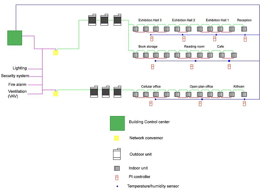
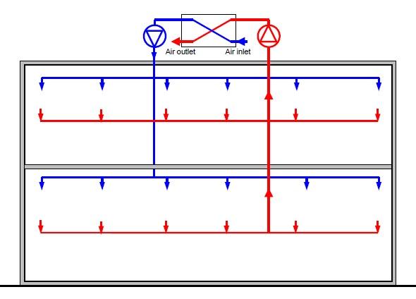
4.2.1.4 The Control Schematic Diagrams for VRF System Schematic diagrams of the VRF control system are shown in Figure 21 and Figure 22. Figure 21 is a wiring diagram that shows how the sensors, controllers and controlled devices are connected. Moreover, the PI controller is wireless and controls the cooling in each zone. The components are then linked with network converters and the control centre, which is further connected to other building systems such as the ventilation system. Figure 22 indicates the locations of the electronic expansion valves near the indoor units. For simplicity, the outdoor units were combined in the drawing. The fan speed will be held constant across the whole system.
Figure 21 Control schematic diagram of VRF system 1
44