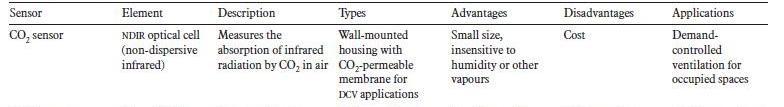
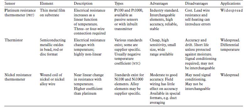
Table 17 CO2 sensor
4.2.2.2 Dampers Ventilation dampers are used to control the flow of fresh air in buildings. Usually in a VAV system, the dampers will be connected to thermostats to control the supply air temperature as part of an air conditioning system. In our building, however, the VAV system is only used for ventilation, thus the dampers are linked with CO2 sensors to control the indoor air quality. The PI controller will alter the output signals, and then the damper will be adjusted via actuator to change the output.
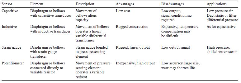
4.2.2.3 Pressure Sensor Similar to the VRF system, pressure sensors are also a part of the control system. These pressure sensors are located in ducts, connected to variable speed devices (VSDs). The VSD controls the fan to alter the velocity of supply and extract air. This is to maintain the constant static pressure of the airflow in both the supply and extract ducts.
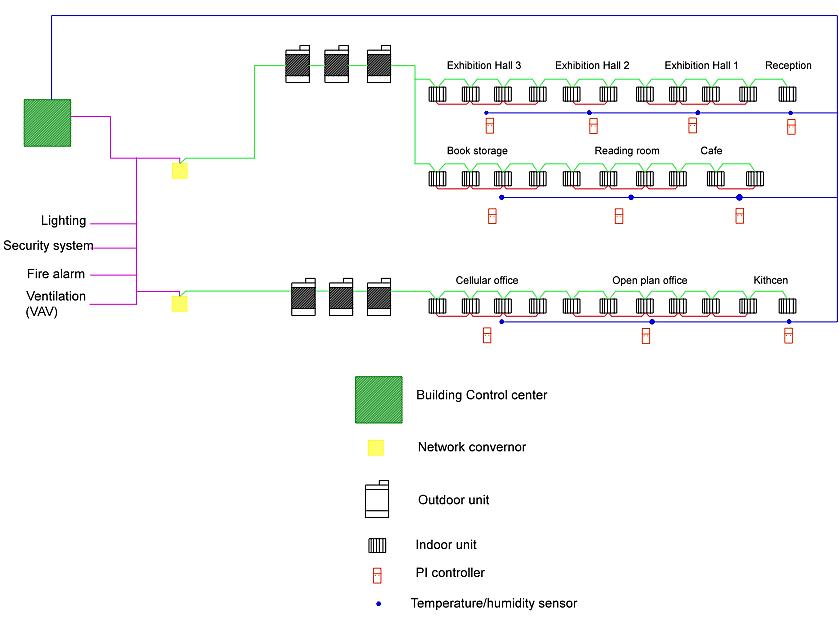
4.2.2.4 The Control Schematic Diagram for VAV System
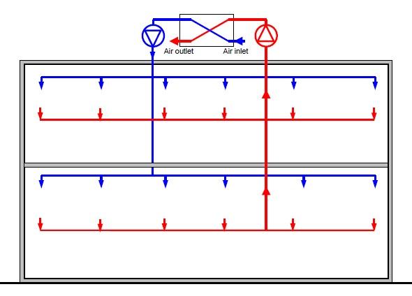
The schematic diagram of the VAV ventilation system is shown in Figure 24. The figure shows the wiring of the CO2 sensors to the control centre, and to the dampers. In addition, there are pressure valves located near the fans, connected via variable speed devices to control the fan speed to maintain the constant airflow.
46