8 minute read
Hybrid systems
Hybrid Systems.
It was previously mentioned that both the KE-DireJet System and KE-Inject System can be regarded as active mixing systems, but this is not necessarily their only function. KE Fibertec AS uses laser technology to facilitate production of more advanced product versions, where passive low impulse ducts can be made more active by laser cutting a number of small holes or inserting nozzles in the textile material.
The more holes or nozzles the system has, the more active the textile ducts will obviously become. This will change how the system works from a passive low impulse system to an active mixing system or what is known as a hybrid textile duct. KE Fibertec markets two products for textile based hybrid ventilation: The KE-Inject Hybrid System and KE-DireJet Hybrid System. These systems are also produced in the form of round (Ø), half-round (D) or quarter-round (½D) ducts. From a ventilation technology perspective, the KE-Inject Hybrid System and KE-DireJet Hybrid System can be regarded as a combination of active high impulse ventilation and passive low impulse ventilation.
Product range: Hybrid systems
KE-Inject Hybrid System
KE-Inject Hybrid System (D)
KE-DireJet Hybrid System
KE-DireJet Hybrid System (D) KE-Inject Hybrid System (½D)
KE-DireJet Hybrid System (½D)
1.8 m
Occupied zone
Occupied zone for hybrid systems
As with low impulse ventilation, the occupied zone is not a standardised area, but a zone which is defined from one project to another in consultation with the architect and client.
The occupied zone is often defined as the zone from the floor up to a height of 1.8 m above people who are in a standing position doing their job, while this height is set to 1.1 m for people who are seated.
Air distribution principle.
In a nutshell, hybrid systems comprise low impulse ducts which are made active by using holes or nozzles. As a result, the low impulse principle is combined with the high impulse principle, whereby part of the air volume in the system is distributed away from the near zone under the ducts.
This offers in particular obvious benefits if cooling is required where ΔT is higher than 5-6°C, as it helps avoid an immediate “cold drop” under the ducts. Instead the cooling load is distributed across a larger area in the room. Hybrid product versions therefore require air velocities etc. to be calculated for both the low impulse and the high impulse section. It must also be ensured, of course, that the air flow from each of these systems does not contribute to any discomfort in the room.
Manufacturing hybrid systems opens up a new world of flexibility, but it is also of paramount importance that you are aware of the requirement specifications for the ventilation system. Just a few rows of holes or nozzles can change the flow from a passive low impulse system to an active mixing system. But the major benefits of this new technology are that you can, in theory, actually dimension one and the same system to be passive in some zones and more or less active in others.
Hybrid systems are absolutely ideal for ensuring that optimum air distribution is achieved in systems with both cooling and heating requirements, as a textile duct with holes or nozzles gives the air energy in the form of movement, as has already been mentioned. This means that air currents are not only reliant upon thermals, as is the case with a low impulse system.
On the other hand, the air which passes through the textile will not make any significant contribution to air distribution in a system for heating. But the air which passes through the textile material does not disappear and short circuit under the ceiling. The majority of it will instead be entrained by the air jets which pass through the holes or nozzles.
Zone 1
The air is delivered partially at high velocity through the holes or nozzles and at low velocity through the textile material. The excess pressure in the centre of the air jets generates an inflow and causes entrainment of room air, as well as part of the duct’s own air. The air’s acceleration under the duct (low impulse flow) is particularly reliant upon the cooling load per running metre of ducting.
Zone 2
The warmer room air is displaced by the cooled air from the duct under the hybrid duct. Part of the low impulse flow is entrained into the high impulse flow. The velocity gradually decreases in the high impulse flow. The velocity decreases in inverse proportion to the distance from the duct.
Zone 3
When entering the occupied zone, it is important to ensure that both the air velocity in the low impulse flow and the air velocity in the jet originating from the holes or nozzles have been adapted to the conditions so that the room’s comfort requirements are met. Zone 1
Zone 2
Zone 3 1.8 m
Hybrid solutions for enhanced comfort.
The job of hybrid textile ducts, as was explained on the previous page, is to shift part of the air volume away from the area under the duct. If you compare this to a low impulse system, a greater cooling load per running metre can therefore be added without generating a draught under the duct.
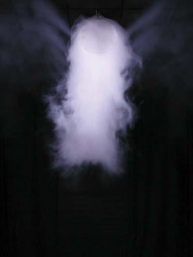
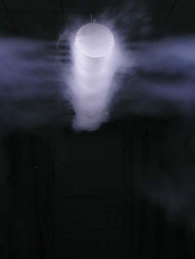
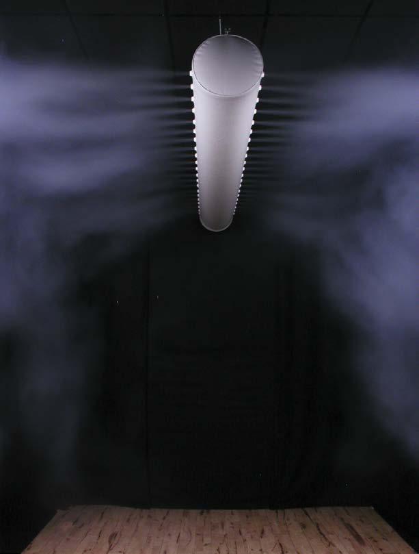
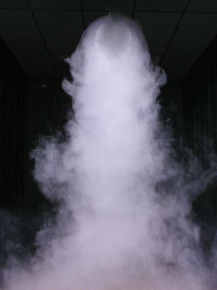
The pictures below show a smoke test where a comparison is carried out between a low impulse system and a KE-Inject System with 20% of the air passing through the holes. Both systems are supplied with the same volume of air at a ∆T of 5°C. It can be clearly seen from the density of the smoke in the near zone under the textile duct what a large difference there is in air velocity under the duct. It is obviously important to remember that the throw length for the air passing through the holes must be sufficient to prevent draught problems in the occupied zone. Changing the number of holes/nozzles in the textile material helps to combine high impulse systems with the low impulse principle, which means that basically three different types of flow patterns can be obtained.
Even a distribution between the textile material and nozzles/holes of 60/40 completely alters the way in which the system operates, from a passive thermal low impulse system to an active mixing system. Even if the distribution between the textile material and holes/nozzles is changed to 0/100, this does not make the flow pattern look noticeably different.
“Smoke test comparing a KE-Low
Impulse System and a KE-Inject Hybrid System. It can be clearly seen from the density of the smoke in the near zone under the textile duct what a large difference there is in air velocity under the duct. It is obviously important to remember that the throw length for the air passing through the holes must be sufficient to prevent draught problems in the area where the high impulse flow penetrates the occupied zone.”

Type of duct Air through holes/nozzles Flow pattern
Low Impulse System 0%
Hybrid System 5-10% upwards
The air drops down right under the textile duct in cooling mode The air drops down directly under the textile duct
Hybrid System 15-30% upwards/side
Hybrid System > 40% Part of the air volume drops. Spread 2-3 m The air spreads in the main direction of the holes
Purpose
Passive thermal displacement/low impulse Coating of ceiling due to condensation problems Spread of near zone when cooling > 5-6°C
Active high impulse system
As can be seen from the table on the opposite page, the number of holes or nozzles per metre of ducting has a major impact on whether the delivery will be diffuse or come from a particular direction. KE Fibertec therefore splits the hybrid systems according to three main principles: model A, model B and model C.
Model A (5-10% through holes/nozzles)
When model A is used, the delivery is very diffuse, similar to low impulse currents. Model A is used especially in premises with high comfort requirements, i.e. room category A+B. The high impulse principle can be beneficially combined with the diffuse flow pattern from low impulse systems if, for instance, there are periods when there is need for heating or the need for more directional ventilation above a particular machine or process. Furthermore, condensation problems on the ceiling in humid premises can also be rectified by simply placing a very small number of hole rows or nozzles, pointing towards the surface of the ceiling.
Model B (15-30% through holes/nozzles)
When model B is used a combination delivery is largely obtained between holes/nozzles and textile materials. Part of the volume flow will in a cooling scenario always drop below the duct, but most of the air is distributed according to the main direction of the holes or nozzles. The combination solution is typically used in premises where there are requirements for both cooling and heating, but with fairly high requirements for comfort in the room, i.e. category B+C.
Model C (>40% through holes/nozzles)
Model C is used for highly directional delivery, which is often used with process-oriented solutions or in large premises, such as sports centres. The air will only be distributed in the main direction of the holes or nozzles, which is the case with KE Fibertec’s conventional high impulse systems. Directional air distribution through the holes/nozzles is incredibly effective and the flexible positioning of the hole rows and nozzles can, in a sense, meet every function in larger rooms.
