21 minute read
High impulse systems
High Impulse Systems.
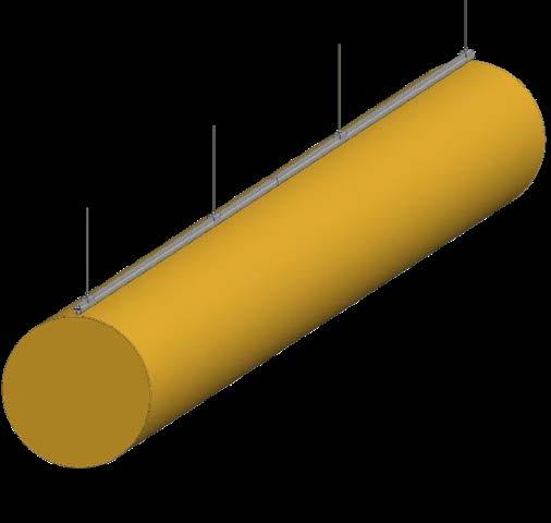
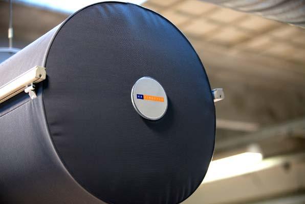
KE Fibertec markets two products for textile based high impulse ventilation: the KE-Inject System and KE-DireJet System. Both these systems can be produced in the form of round (Ø), half-round (D) or quarter-round (½D) ducts. The KE-Inject System comprises groups of holes in the textile duct, while the KE-DireJet System comprises rows of conical nozzles specifically for directional air distribution. From a ventilation technology perspective, both the KE-Inject System and KE-DireJet System can be regarded as high impulse systems for mixing ventilation. For this reason, one general air distribution principle will be described for these systems, while the specific product features will be described separately.
Product range: High impulse systems
KE-Inject System
KE-DireJet System KE-Inject System (D)
KE-DireJet System (D) KE-Inject System (½D)
KE-DireJet System (½D)
1.8 m
Occupied zone
1.8 m
Working zone Occupied zone
Occupied zone for high impulse systems
As with low impulse ventilation, the occupied zone is not a standardised area, but a zone which is defined from one project to another in consultation with the architect and client. The occupied zone is often defined as the zone from the floor up to a height of 1.8 m above people who are in a standing position doing their job, while this height is set to 1.1 m for people who are seated.
Working zone for high impulse systems
In the case of industrial premises, it may also be appropriate for high impulse systems to divide the room up into a working zone as the state of the air may vary from the general level as a result of industrial processes. Heat and pollution sources are often present which require special measures to be able to maintain a satisfactory indoor climate in the working zone. If processes are carried out which cause extreme pollution, textile based ventilation should therefore be supplemented with local extraction vents.
Air distribution principle.
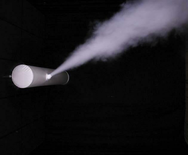
KE Fibertec’s high impulse systems are based on mixing ventilation and are characterised by the fact that air is delivered at a high velocity outside the occupied zone. The high air velocity rate in the air jet will generate excess pressure, resulting in an inflow and entrainment of room air towards the air jet supplied.
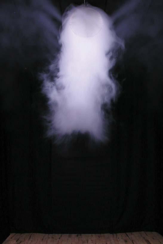
During the first air flow cycle the air velocity will be high, but as the volume of room air that becomes mixed increases, the air velocity will decrease. If the system has been dimensioned properly the delivered air volume will be completely mixed with the room air before it reaches the occupied zone and the air velocity rate has dropped to the desired level, depending on the room category. In a mixing ventilated room air velocities, air temperatures and humidity will be distributed identically and in theory, the air quality will be the same everywhere in the room. A textile based high impulse system, unlike its low impulse counterpart, can be used for cooling, ventilation and heating. The reason for this is that KE Fibertec’s high impulses systems, unlike its low impulse systems, are less dependent on external effects, such as convective heat currents in the room. The supply air is delivered with high initial energy in the form of velocity (momentum) through holes or nozzles, with the effect that the air is discharged into the room instead of being distributed through a textile surface at low velocity. This means that KE Fibertec’s high impulse systems have what are known in flow engineering as a throw length and penetration length.
Compared with low impulse systems, the location of the exhaust grilles is only of minor significance to the air flows in the room. In practice, they are often positioned along the ceiling. The picture below illustrates the air distribution principle for high impulse ventilation.
Zone 1
The air is delivered at high velocity, often up to 15-18 m/s, through the holes (KE-Inject System) or nozzles (KE-DireJet System). This generates excess pressure in the centre of the air jets, resulting in an inflow and entrainment of the air in the room towards the air jet supplied.
Zone 2
As the volume of entrained air increases, the air velocity in the flow gradually decreases. The velocity decreases in inverse proportion to the distance from the duct.
Zone 3
In premises where a certain comfort level is required, the air velocity at the entrance to the occupied zone must be adapted to the conditions, which mainly depend on the level of activity of the people working there and what they are wearing (room category). To ensure that a suitable air velocity is achieved, the distance from the duct to the occupied zone must be greater than the calculated throw length (see definition on page 43).
Zone 1
Zone 2
Zone 3
1.8 m
Short circuiting warning.
It is important to be aware that mixing ventilation also entails a risk of the supply air being short circuited (accumulated under the ceiling). This problem may occur if overheated air is supplied combined with an excessively low discharge velocity, or if there are strong upward currents in the premises, preventing the air from reaching the occupied zone.
This problem becomes particularly apparent when the ∆T is more than 7-12°C. In the best case scenario, the poor heat distribution in the room can be compensated for by raising the supply temperature, but if the heating coil in the air conditioning unit does not have sufficient capacity to do this, the temperature in the occupied zone will fall. This situation is very inconvenient, both from an energy and comfort perspective. To make sure that short circuiting is prevented, heated air must only be delivered if the supply temperature and discharge velocity are adjusted. This means that the warmer the supply air, the higher the discharge velocity needs to be to ensure that the air reaches the occupied zone. If the ceiling is particularly high (h > 8-10 m) the ducts need to be dimensioned for a high static pressure to be able to push the air down into the occupied zone. If this is not possible, the ducts can be positioned at a height of 5 metres, for instance.
Occupied zone

Free jet
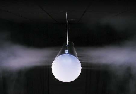
If the air jet is directed outwards into the open room, this is what is known in flow engineering as a free jet. The turbulent air jet entrains air from its surroundings and the jet’s diameter increases in proportion to the distance from the duct, while the velocity in the jet decreases.
Wall jet
If the air jet is directed towards a surface, this is what is known in flow engineering as a wall jet. The flow can be regarded as a bisected open jet as the surface can be regarded as a plane of symmetry. The maximum velocity is achieved close to the surface and is 2 greater than the equivalent velocity for an open jet at the same distance from the duct.
Free jets and wall jets.
A crucial factor for the air distribution principle behind the KE-Inject System and KE-DireJet System is the main direction of the air jets. If the jet is directed outwards into the open room, this is what is known in flow engineering as a free jet and if the air jet is directed at a surface, this is a wall jet. The difference between these two flow phenomena is their ability to entrain room air. If the jet is directed towards the ceiling surface it will try to “stick” to this surface because a negative pressure is generated between the jet and the ceiling as no replacement air can be supplied for the volume of room air entrained by the jet. This is known as the “Coanda effect” and it 2 increases the throw length by a factor of in relation to the throw length for a free jet, while the velocity rate in the jet decreases proportionally more slowly. The air velocity needs to be a minimum of 0.35 m/s to be able to utilise the Coanda effect.

Throw length
The throw length is defined as the largest distance from the supply duct to a specific point in the premises where the air velocity is precisely equal to the desired final velocity, e.g. viso = 0.20 m/s. It is important to note that the throw length, by its definition, is valid in isothermal conditions. As a result, the calculations for air velocities must be corrected if the supplied air is either colder or warmer than the surrounding room air.
The throw length for a wall jet is 2 longer than for an equivalent free jet. The reason for this is that a wall jet will stick to the ceiling due to the Coanda effect and as a result, only half the volume of room air contributes to reducing the velocity rate.
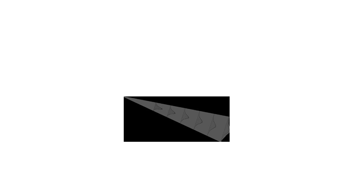
l0.20
l0,200.20 viso = 0,20 m/s 0.20 m/s
viso = 0,20 m/s
0.20 m/s
Thermal penetration length
The thermal penetration length is absolutely crucial in determining whether the air is actually distributed as expected. The theory underlying wall jets is actually based on the fact that the jet will not become so “heavy” that it will leave the ceiling’s surface before it is supposed to. If it does, the air velocity at the entrance of the occupied zone will be higher than calculated. This means that it will feel uncomfortable for anyone located in the zone affected by the jet. To prevent any drop of cold air, the thermal penetration length must be checked to see that it is at least 75% of the horisontal distance along the ceiling, L, where the air is moving.
minumum 0,75 x L minimum 0.75 x L L
Using flow models.
Both the KE-Inject System and KE-DireJet System are highly flexible systems and any direction at all can be chosen for the air jets. It is obviously important for the air jets to point in the main direction of the air flow following the desired air flow pattern in the room. As mentioned earlier, it is also important that the air flow is directed downwards towards the occupied zone when heating is required in order to prevent short circuiting.
Apart from choosing the main direction for the air jet, secondary nozzle positions can be used. For instance, if the ceiling needs to be coated locally to avoid the formation of condensation or part of the area needs to be cooled down/heated, it is possible to direct individual nozzles or holes towards the relevant area. Nozzles can also be left out entirely in sections of the duct if no air needs to be supplied.
KE Fibertec uses three different flow models for textile based mixing ventilation in its everyday activities, which are flow models 1, 2 and 3 respectively. To be able to use KE Fibertec’s datasheets properly, you need to know which flow model is involved as all the datasheets have been specified for flow models 2 and 3, i.e. free jets. It is important therefore to clarify what the user wants and needs in terms of the system, as well as to become familiarised with processes and activities before starting to dimension the final design for the high impulse system. Using flow model 1 (wall jet) can bring some benefit, even though the throw length increases as a result of the Coanda effect. Air jets tend to become more stable when cooled air is delivered, while the risk of a drop of cold air or draughts in general in the occupied zone is kept to a minimum.
The Coanda effect also makes the blanket of air “stick” to the ceiling, which means that it will not be deflected by local heat sources, obstacles etc. Consequently, there is a greater likelihood of achieving the desired flow pattern in reality than with delivering an free jet. As was mentioned before, it is recommended to use flow model 2 or 3 for both the KE-DireJet System and KE-Inject System if the system is going to be used to provide heating. This will then eliminate the risk of the supply air being short circuited.
All KE Fibertec’s textile based ventilation solutions are 100% customised. Any direction can be chosen for the holes in the KE-Inject System and for the nozzles in the KE-DireJet System. Depending on the system’s usage, the holes/nozzles can be pointed in any direction, specified at an angle from 12 o’clock.
-60°
-90°
-120° -30° 0°
30°
-150°
180° 150° 60°
90°
120°
Flow model 1 Flow model 2 Flow model 3


KE-Inject System
The KE-Inject System offers so much flexibility. It has been upgraded with a new family of multiple sized laser cut holes. The Inject system is divided into four families. The conventional Inject system consists of three different groups of fixed patterns (LV, MV and JET) all made with small Ø4 mm holes for comfort solutions. The new Inject Flex family comprises three different groups (S, M, XL) of customised hole sizes. The Inject Flex S has a hole diameter of 4 and 6 mm. Inject M comes with hole sizes from 6-25 mm, and the long throw Inject XL family comes with hole sizes from 35-70 mm diameter.
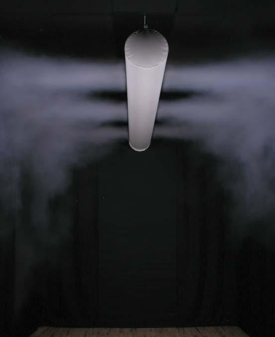
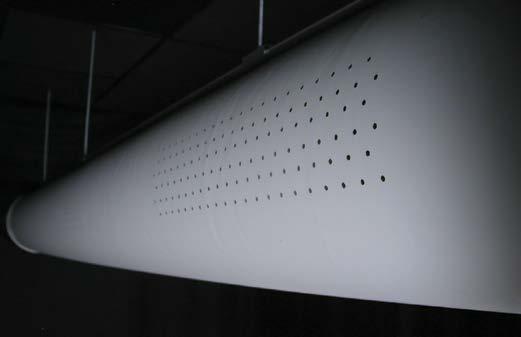

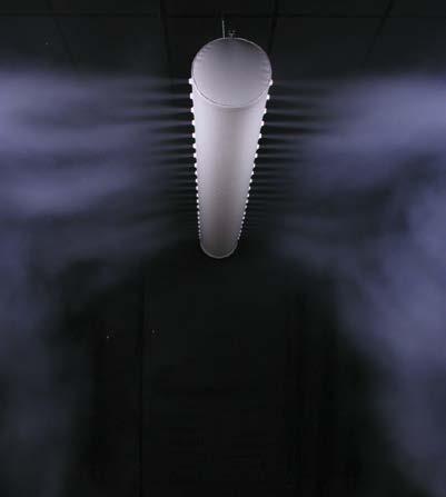
The KE-Inject System comprises small holes in coated textile material (airtight). The delivery of air through the holes causes induction of the room air on a large scale, resulting in a relatively rapid reduction in the air velocity rate in the jet compared to the KE-DireJet System.
KE Fibertec markets three types of conventional Inject products (LV, MV, JET) with their characteristic patented hole design running in pattern sections along the duct’s longitudinal surface.
The special hole pattern produces an excellent induction effect where the secondary room air is mixed very fast, which reduces the air velocity in the jet and thereby the risk of draughts in the occupied zone. KE Fibertec has well-documented measurements of pressure loss, throw lengths and air penetration for the three conventional Inject types where the final design is based on the these hole patterns. If the system layout requires more design flexibility, KE Fibertec recommends the KE-Inject Flex System.
Conventional KE-Inject (LV, MV, JET).
The special hole design produces an extremely good injection effect, i.e. the air jets operate like a row of small missiles. The high velocity rate generates a relatively large amount of low pressure behind the jets, which is crucial to the inflow of room air from zones around the KE-Inject duct.
The injection effect can be improved further if the air jets are directed towards the ceiling because the inflow of room air is reinforced as the heat naturally rises upwards in the premises. Another benefit from grouping the holes in a particular design is the opportunity it provides to control the flow. The air jets from the many holes will see their angle of propagation continually increase as room air is entrained and mixed. After a short time the air jets will converge and continue like a single blanket of air. If the holes are grouped with a large distance between them a larger volume of room air needs to be mixed before the air jets converge and form an air blanket than if the holes are placed in a hole design with a small distance between them. As the drop in velocity in the jet mainly depends on how much room air is mixed in, it is obvious that KE Fibertec can control the flow very precisely by changing the hole design.
If the requirements are for short throw lengths and a large mixing capability, a KE-Inject Low Velocity System is used, with a large distance between holes in the groups of holes. Similarly, the KE-Inject JET System is used with a small distance between the holes if the blanket of air has a larger stretch to overcome. In these situations the KE-DireJet System is also ideal.
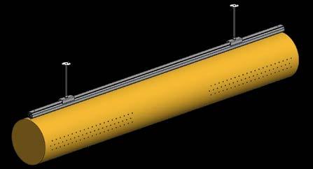
KE Inject Low Velocity (LV)
Hole size: Ø4 Suitable for both heating and cooling Extremely high induction effect (up to 15x) Hole sections divided 50/50% per m Air flow: 11.5 m3/h per m at 120 Pa (1 row)


KE Inject Medium Velocity (MV)
Hole size: Ø4 Suitable for both heating and cooling High induction effect Hole sections divided into 75/25% per m Air flow: 18 m3/h per m at 120 Pa (1 row)
KE Inject Jet (JET)
Hole size: Ø4 Suitable for both heating and cooling Efficient for spot or close-up ventilation Holes 100% - no sections (similar to a linear slot diffuser) Air flow: 23 m3/h per m at 120 Pa (1 row)
KE-Inject Flex (S, M, XL).
KE Fibertec has introduced a new flexible Inject family called Inject Flex. Unlike the conventional Inject family made with sections of hole patterns, the Inject Flex system can be made with an almost unlimited configuration with multiple patterns and orientations to perform in every environment from comfort to industrial.
At the same time, the Inject Flex can be made of every available customised material from KE Fibertec so that the flow pattern can be combined in an endless configuration, including a Cradle to Cradle certified solution.
How it works.
KE Fibertec’s Inject system functions by supplying air into the room at a high velocity in the primary jet. The supply air mixes with room air, gradually reducing the air velocity prior to entry into the occupied space. As the number of holes per metre may vary, all jets will impact on each other. With only one or a few holes per metre, the individual jet will act like a circular 3-dimensional jet, but with the maximum number of holes per metre, the air flow will change character to a 2-dimensional jet. The Inject Flex system can also be configurated as a linear slot diffusor. These different design factors have already been taken into account in KE Fibertec’s TBV Designer software.

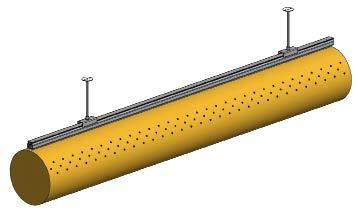

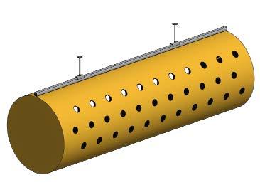
KE Inject Flex S
Hole size Ø4 and Ø6 mm Made with 21 holes or 42 holes per metre Suitable for both heating and cooling Air flow: 0.5-1 m3/h per hole at 120 Pa Short throw lenghts
KE Inject Flex M
Hole size Ø6, Ø12 and Ø25 mm Made with 1-14 holes per metre Suitable for both heating and cooling Air flow: 1-15 m3/h per hole at 120 Pa Medium throw lengths
KE Inject Flex XL
Hole size Ø32, Ø50 and Ø70 mm Made with 1-6 holes per metre Suitable for both heating and cooling Air flow: 30-130 m³/h per hole at 120 Pa Long throw lengths
Product features of KE-DireJet Systems.
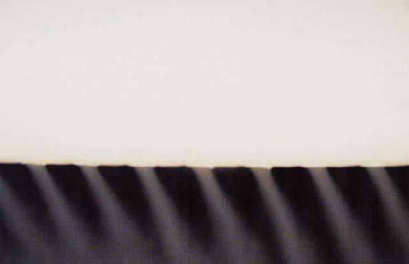
The key difference between the KE-Inject System and KE-DireJet System is their ability to entrain room air. The KE-DireJet System is made of a coated or permeable textile material with rows of conical nozzles for 100% active, directional delivery.
The conical nozzles limit the induction of room air around the individual air jet, whereby the velocity in the jet decreases relatively slowly compared to the KE-Inject System. As a result of this, both the throw length and thermal penetration length are extended considerably for the KE-DireJet System.
KE Fibertec is the only distributor of textile ducts that offers five different nozzle sizes: Ø12, Ø18, Ø24, Ø48 and Ø60 mm. The flexibility in the choice of nozzle size offers great benefits as the KE-DireJet System can be used in virtually every type of premises that requires mixing ventilation, even in extremely large premises, such as high-bay warehouses or large sports arenas. The nozzle size and flow model naturally depend on the requirements specification for the ventilation system, and KE Fibertec will obviously advise on the best choice of nozzle size and direction. Ducts are often used with different nozzle types and flow models in the same duct. This allows you to achieve the flow pattern and air intensity in the various zones exactly how you want.
The conical nozzles are fitted in holes made of coated polyester fabric and are secured using a locking ring. The maximum number of nozzles per row per metre is 14 for the Ø12, Ø18 and Ø24 mm nozzles. If this is not sufficient, it is recommended using two or more rows of nozzles.
In the case of Ø48 mm and Ø60 mm nozzles, it is recommended using a maximum of six nozzles per metre. As the number of nozzles per metre is increased, the individual jets will have an impact on each other and they will change character from circular jets to 2-dimensional jets.
The velocity rate in the flow will also slow down as the induction of room air is limited the closer the nozzles are placed together. These factors are naturally included in KE Fibertec’s datasheets.
The nozzles can be supplied with nozzle plugs to block the air flow temporarily in certain zones. This is used most often in cases where the system’s features need to be changed for a period of time, for instance, if the premises’ use changes.
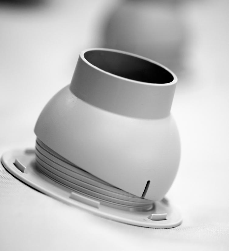
The Vario nozzle for directional air distribution
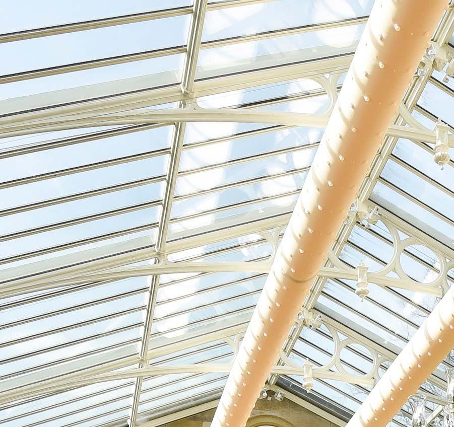
The KE-DireJet System is often used in large premises with large throw lengths. The choice of nozzle depends on the system’s performance, the relevant room and the indoor climate requirements.
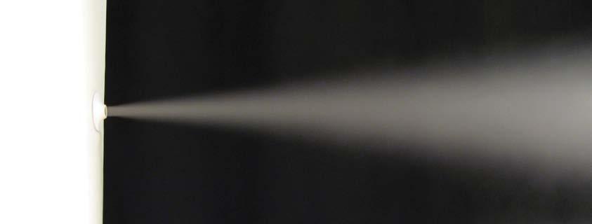
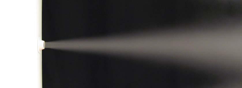
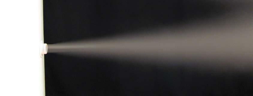

Ø12 mm nozzle
The Ø12 mm nozzle is used where directional delivery is required in a room and comfort requirements are important. Each nozzle delivers 5 m3/h with a static pressure of 120 Pa. See datasheet 16 for further information.
Ø18 mm nozzle
The Ø18 mm nozzle is used where directional delivery is required and often in process-orientated solutions, in a room where relatively large throw lengths are required. Each nozzle delivers 11 m3/h with a static pressure of 120 Pa. See datasheet 16 for further information.
Ø24 mm nozzle
The Ø24 mm nozzle is used for directional delivery in a room with large throw lengths. Each nozzle delivers 20 m3/h with a static pressure of 120 Pa. See datasheet 16 for further information.
The Ø48 mm nozzle is used for directional delivery in a room with very large throw lengths. The flexible nozzle can be turned 30° in any direction around the nozzle’s centreline. Each nozzle delivers 81 m3/h with a static pressure of 120 Pa. See datasheet 17 for further information.
Ø48 mm nozzle (DireJet Vario)
Ø60 mm nozzle
The Ø60 mm nozzle is made up of the bottom of the Ø48 mm nozzle and is used for directional delivery in rooms with very large throw lengths. Each nozzle delivers 139 m3/h with a static pressure of 120 Pa. See datasheet 17 for further information.

KE-DireJet Vario - The flexible solution
The latest development of the KE-DireJet System is called KE-DireJet Vario. It is a multi-adjustable nozzle that allows the direction of the air jet to be freely adjusted up to 30° in any direction in relation to the nozzle’s centreline.
When dimensioning a system, KE Fibertec takes as its starting point the room’s layout and function so that the nozzles are basically placed in the correct position (nozzle adjustment 0°).
-30°
The KE-DireJet Vario nozzle can be adjusted manually so that the main direction of the air jets can be changed by up to -30° in relation to the nozzle’s centre line. This may be particularly appropriate if the room’s layout is changed after installing the system. This nozzle adjustment can also be used in situations where a large cooling load needs to be supplied in the room.
The manual adjustment can also change the main direction of the air jets by up to +30° in relation to the nozzle’s centre line. As mentioned above, this may be particularly appropriate if the room’s layout is changed after installing the system. This nozzle can provide great benefit if it is used in situations where a large heating load needs to be supplied for the room.
+30°
