3 minute read
Maximum inlet velocities in TBV-systems


Entrainment in textile ducts
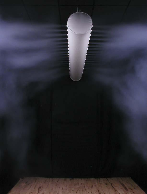
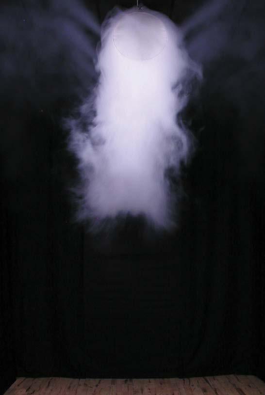
It is well known in flow engineering that holes positioned with a perpendicular direction in a long main duct can cause problems. The main problem is that the air has a tendency to veer away and flow parallel to the main duct, unless the holes or nozzles are fitted with baffle plates.
In the vast majority of cases, entrainment will cause problems with air distribution in the premises. At one end of the room (nearest the inlet), problems may arise with stagnant air, while at the other end of the room, entrainment may be the cause of major draught problems. Entrainment occurs if the inlet velocity is significantly higher than the outlet velocity through the holes in the textile material. To counter this inconvenient deflection of flow (entrainment), KE Fibertec recommends that the outlet velocity through the holes be at least 35% higher than the inlet velocity in the duct.
Another factor which has an impact on entrainment is the size of the hole that has been cut out. If air is supplied through large holes it will always have a tendency to deviate and flow along the duct.
The KE-DireJet System never has problems with entrainment. The nozzles are designed with a length that ensures the air is discharged perpendicularly to the main duct. In the KE-Inject System the holes are cut directly in the textile, which means that the use of baffle plates is not an option. On the other hand, entrainment does not occur to such a noticeable extent in this case either. The reason for this is because the air velocity at the centre of the hole, i.e. perpendicular to the main duct, is usually higher in the KE-Inject System than in conventional systems.
Permeability.
Air permeability through the textile material’s surface is crucial to how great the static pressure will be for a given volume flow. The tighter the material’s weave, the higher the pressure will be as a function of volume flow.
For all KE Fibertec’s low impulse materials, the static pressure increase is given as a function of volume flow per m2 of the textile material’s surface. Permeability is expressed in the unit [m³/m²/h]. See datasheets 6 and 7 for more information.
Maximum inlet velocities.
The inlet velocity is a critical design parameter for textile based ventilation systems as it has a major impact on aspects such as pulsation, noise generation, the material’s durability and the air distribution from the duct. The recommended inlet velocity for round ducts is no more than 6-8 m/s, depending on the entry method. In the case of KE-Interior Systems, air velocities of between 4 and 7 m/s may be permitted, depending on the entry method.
Max 4 m/s Max 4 m/s
Max 4 m/s Max 4 m/s
Max 6 m/s Max 6 m/s
Max 7 m/sMax 7 m/s
Max 6 m/sMax 6 m/s
Max 7 m/s Max 7-8 m/s
Max 7 m/s Max 7 m/s
Outlet velocities - Low impulse.
The outlet velocity through textile based low impulse systems depends on the geometric surface area as the air is slowly diffused through the whole surface of the textile material.
Outlet velocities – High impulse.

The static pressure keeps the textile based ventilation system inflated, but the static pressure pushes the air out through the holes/nozzles and if necessary, through the textile material. The outlet velocity is a very significant parameter in the calculation of the throw length, thermal penetration length etc., but in reality, it is very difficult to measure.
On the other hand, any calibrated manometer can be used to measure the static pressure in the duct. With a standardised hole design and a detailed knowledge of the properties of the holes and nozzles, any given outlet velocity will always correspond to the same static pressure in the duct.
As already described on the opposite page, the air velocity in the KE-Inject System must be adapted to the outlet velocity. The minimum requirement is for the outlet velocity to be 35% higher than the inlet velocity.


