AMPHIBIOUS URBANISM

PRINCIPAL INVESTIGATOR:
ERIK G L’HEUREUX RESEARCH ASSISTANT: ANIRUDH CHANDAR
DEPARTMENT OF ARCHITECTURE
SCHOOL OF DESIGN AND ENVIRONMENT
Amphibious Urbanism : A prototype for Hydrological Architecture
Department of Architecture, School of Design and Environment, National University of Singapore
4 Architecture Drive, Singapore 117566
Tel: +65 65165186
Email: arch.nus.edu.sg
Funded by MOE AcRf Tier 1 Research Grant WBS Number : R-295-000-105-112
National University of Singapore
© Individual contributors
All rights reserved; no part of this publication may be reproduced, stored in a retrieval system, or be transmitted in any form or by an means, electronic, mechanical, photocopying, recording or otherwise without prior written permission of the publisher
The publisher does not warrant or assume any legal responsibilty for the publications contents. All opinions expressed in the book are of the authors and do not necessarily reflect those of the National University of Singapore.
Department of Architecture
PI: Erik G L’Heureux AIA, LEED AP
RA: Anirudh Chandar
Book design: Anirudh Chandar
.Preface
.Precedents
.Components
.Aggregation
.Unit
.Bibliography
Preface
Surrounded by the Andaman Sea and the South China Sea, the domain of South East Asia extend approximately 5000 kilometres from Myanmar to the east of Indonesia. South East Asian civilizations, their culture and architecture have been deeply invested and dependent on the utilization of water through the ages. [ii]
These bodies of land are irrigated by rivers (such as the Irrawaddy, Salween, Chao Phraya and Mekong) which have given birth to some great Asian civilizations. These rivers were crucial in activating the growth in trade for economy and culture within and beyond its region.[iii]
Being such a water-locked territory, their reliance on the water developed as both a necessary adaptation to the environment as well as a fundamental human trait to build settlements close to water.
The representation of the South East Asian archipelago in early mappings as hydro centric models albeit exaggerated, reflect the importance of the surrounding waterways and their ability to define the culture, functioning and inherently the architecture that manifests in these locations. The archipelago and the density of island clusters it contains similarly gave rise to early impressions.
With the development of the region, the impressions were amended to accuracy to create navigable maps for seafaring trade routes.


The utilization of water took place in two forms - the surrounding water-bodies acted as a connecting medium between the archipelago to be utilized for trade routes and transport, while the inland rivers (fresh water sources) acted as birthing grounds for inhabitation.
Within this dense island cluster, the Sijori region was established in 1994 between three countries, namely - Indonesia, Malaysia and Singapore, to strengthen economic links in the region and optimise complementarity between the three countries. It began as the SIJORI Growth Triangle in 1989, which includes Singapore, Johor and part of the Riau Islands Province (In Indonesia, specifically the Riau Archipelago). [iv]
Singapore, an island city-state located in the Malay archipelago, stands within the larger urban context of Johor and the Riau archipelago - a composition of eight million peoplehosting complex relationships with the sea that binds the territory together. Within this hydro-centric territory lies a series of urban relationships between land and sea, offering new approaches to inhabitation, density and climate change that supersede terra-centric growth.
Inhabitation within Singapore began - as with most South East Asian cities - as hydro centric dwellings, extending from agricultural river bed dwellings to coastal kelongs and floating/pile fisheries.
This historical incentive towards utilization of hydrology has remained and still exists today in various forms ranging from highly formal and organized concrete pile dwellings (Kelongs in the locals of Pulau Buluh and Kukup amongst others) to extremely informal bakau pile fisheries (Johor Straits).
Trading routes through the Sijori region reinforced the utilization of water enabling the development of Singapore as a vital port city embedded in a prime location within southern Asia. Global trade skyrocketed Singapore’s economic growth facilitating its transfor mation into a first world country through rapid urbanization and densification.


region Topography | 1:400,000 [i]
This historical dependence on water albeit facilitating civilization, trade and growth, creates unique problems.
Current day South and Southeast Asia house 250 million poor rural people in the low-lying river mega-deltas.
60 to 100% of the population in 4 ASEAN countries lives in coastal areas, with the remaining countries being reasonably high as well. This large percentage of coastal residents may be due to greater socioeconomic opportunities in the coastal areas, regardless, this coastal dependence also creates a large population that is at risk of sea level rise. [vi]
The majority of the worlds at risk population is centered around asia and more specifically around south east Asia despite being geographically so small.
The total estimated population at risk of exposure to regular flooding stands at 180 million with south east Asia alone accommodating 50 million
Percentage of coastal population distribution
Population at immediate risk of sea level rise
Boxes represent coastal countries and are sized according to the number of people expected to be exposed to regular ooding by 2100.
Based on chart by http://www.climatecentral.org/news/new-analysis-global-exposure-to-sea-level-rise- ooding-18066
The importance of the port and its geographical positioning is one of Singapore’s greatest assets and the reason for its present day success. However, water now poses a crisis to Singapore and the rest of South-East Asia due to concerns of the rising sea levels and flooding due to climate change as well as the booming population growth in the region, leading to greater stress over dealing with high density living. Singapore is a prime example of a country-state that is surrounded entirely by water and has largely depended on its water in the past. With her naturally low and flat topography, Singapore is at risk of flooding as one result of climate change.
As with other Southeast Asian counties, Singapore faces rapid population growth, requiring meeting the needs of its massive population within an extremely limited and quickly depleting land area of only 720 square-kilometres. More importantly, Singapore needs to meet the demands and provide livable space to its people. Early solutions such as building dykes in the seas and the great dependence on land reclamation are slowly meeting their ends as they faces many limitations geographically, economically and politically.
“Since 1991, all new reclamation projects have to be built to a level 125 cm above the highest recorded tide level. This is 66 cm more than the IPCC’s projected highest sea level rise of 59cm by the end of the 21st century in the worst-case scenario. Singapore, is as such, well prepared for any further increase in sea level arising from climate change within the range of over one meter.” [vii]
This drastic policy making in response to the IPCC report, may deal with the immediate threat of sea rise but increases the severity of reclamations ecological impact by requiring a higher plinth to build on. It is therefore pertinent to begin thinking of alternatives to creating “new ground” through reclamation or literal territorial expansion and return to the symbiotic relationship with water in all forms including inhabitation. [viii]
Reclamation over Time


Typologies | 1:250,000 [i]
This intention for rapid economic growth has caused a shift of focus from low rise informal hydro centric structuring to industrial scale Terra centric high rise construction, which, although necessary for the intense economic growth has caused a decapitation of Singapore, it’s population and inhabitation from its coastline.
The focus of this project is on this historically rich site of urbanisation that has been repressed as a result of Singapore’s trajectory towards temperate modernization and terra centric development.
The intention is to reclaim this space and utilize the potential it offers for urban expansion. Singapore houses a unique problem in its industrial, military and other tertiary requirements taking up a large portion of the coastline. Some of these programmatic barriers can hopefully be reclaimed for the purpose of inhabitation


Precedents
The process of reclaiming this coastal space begins with the study of existing sustainable hydrological precedents within Singapore in the form of Kelongs.
Kelongs embrace and have stood for the utilization of water as both a means to food (aquaculture) and shelter (as low cost housing). Singapore’s locational and historical involvement with water and necessity for a more ecologically sustainable means of urban expansion are enabled by the adoption of the ideology behind kelongs in utilizing water to generate architectural formal housing systems for deployment.
Hydrological architecture as a concept however, goes beyond a contextual or historical precedent and deals with resilient and opportunistic means of providing housing due to worldwide concerns of global warming and massive population growth. We look at manifestations of architectural desire to build on water in both realized and unrealized forms.
Three Kelong communities, namely - Kukup, Senggarang and Pulau Buluh, are studied to help develop a vocabulary of hydrological living and architecture.

With the introduction of water-based architecture, there is a shift in the normative perception of structure and functioning within a building from a grounded to a floating/ stilted building.
This offers opportunities as well as constraints in various forms, both architectural as well as operational and climatic.
The notions of being static and permanence which comes with land dwelling have to be replaced with change, flexibility and adaptability on water. [x]
The same applies for urban or infrastructural planning. For instance, high rise structures are not feasible/economical due to their heavy reliance on a strong foundation which is hard to create over water - every increment in height would imply exponential increments in foundation depth or base flotation device area. Similarly, principles of privacy and accessibility need reconsideration before they can be deployed on water.
It is necessary therefore that the context, climate and ocean topography would dictate the nature of the urban hydrological fabric and its deployment. [xi]
Some of the historically dealt with differences between land and water based structures can be gleaned through the investigation of these exemplary Kelong communities beginning with Senggarang.


The water settlement of Senggarang is located on the Riau island of Tanjung Pinang, Indonesia. Within approximately 13 hectares, Senggarang contains about 230 homes, with an average of 4 people per household, bringing the approximate population to 920. [xiii]
Natural land formations of the bay and island clusters to the west protect Senggarang from strong waves.
Located next to a mangrove swamp, the ground is unfavourable for land based construction which necessitated stilt construction.
The concrete piles allow for a more formal structure upon which the unit can be placed as opposed to the more common wooden piles.
A primary difference between land and water based construction is the lack of attachment to the floor. This allows for radiative cooling of the house due to its detachment.
These units adopt several land based architectural elements such as the porch and the formal pitched roof. Parallel arrangement of the units with openings only towards the water and the pier allow for privacy between units.


Senggarang Aggregation
Senggarang Single Unit Axonometric


Pulau Buluh is an offshore island located to the south west of Batam, between Pulau Teluk Sepaku and the mainland. [xii]
The total area excluding island’s land area is roughly 9.4 hectares and currently houses 400 homes with 4 persons per household on average. [xii]
Pulau Buluh is located in the middle of a narrow body of water separating two land masses - a channel system.
The settlement is completely water-locked with a water depth of up to 15 meters, but being protected by the mainland, it faces little current to threaten its stability. Accessibility is a problem for the settlement as the residents need to travel across the water to Batam on a daily basis.
The reason for the shift to water based dwelling was the undulation of the topography of the land.
The units are relatively closer together than in Senggarang to deal with the depth of the water. The wooden piles create much more stable structures when the units are built as combined structures.
Being closer together, results in a reduction of privacy for the residents of Pulau Buluh while promoting a strong sense of community due to the settlement’s distance from the mainland.


Located along the straits of Malacca in Johor, the Kukup water settlement is, positioned between the mainland and a nautre reserver island - Pulau Kukup. [xvi]
Kukup has approximately 340 stilted homes with an average of 5 persons per household over a sea plot area of 14.7 hectares.
Kukup’s settlement is protected from open seas by the nature reserve, yet the location witnesses trade ship passage.
Due to the safety from rough waters provided by the nature reserve, the locale is ideal for fish and fishing which makes up the majority of the demographic’s occupation. With a relatively low water depth of 0.6 metres, the original occupants built upon wooden piles which have since been replaced with concrete piles. [xvii]
Kukup remains relatively close to land due to the swampy nature of the soil found in the region. This closeness to the mainland proper results in a lack of communal independence and therefore privacy.
From the reading of these three cases, there exists a clear corellation between the nature of the community, its structuring, typology and urban planning to the location it is built on, its soil, water current, water depth etc. The adaptibility of these communities ensure their survival.
These locational factors weigh in to the selection of a site for the implementation of the hydrological proposal.


Kukup Single Unit Axonometric
Progressing from local to global precedents, the investigation shifts to both fabricated metropoli and organic manifestations of hydrological urbanism globally. Having set up a vocabulary for the requirements of a site, this section seeks to investigate the features of the urban model, its organization and infrastructure.


venice
Natural aggregation
The most organic form of hydrological architecture which began as small colonies and grew into a city of 60,000 [xviii]. The architecture itself is immobile and the buildings are on stilts therein not dealing with flotation explicitly. It began as an informal community but transitioned into structured growth as its scale expanded . All mobility is facilitated by extraneous services. An informal cluster of hydrological urbanism that is adhesed by the proximity between the blocks and some interior roadways.
Tokyo Bay - Kenzo Tange Infrastructural aggregation
An alternate to the tetrahedron high rise structure in Tokyo bay was proposed by Kenzo Tange in a low rise urban sprawl that stretched across the bay.
Kenzo tange utilizes Tokyo’s proximity to a bay to expand the city along a linear axis connecting two sides of the bay while creating a hydrological urban infrastructure. The residential growth is perpendicular to the linear axis across the bay and supported on large floating platforms. The monumental axis built across the Tokyo Bay was designed for cars, keeping pedestrians away in separate areas through a hierarchy of expressways.
“Pilotis areas constitute spatial links between public and private areas. They are the areas in which the flow of traffic meets with stable architectural space. Core systems, on the other hand, link urban arteries with the buildings.” [xix]
The system is designed to bridge across Tokyo Bay and is limited by its span. Its utilization in other locations is therefore dependent on applicability to the location unlike triton city.


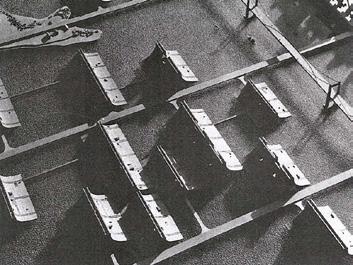

Triton City - Buckminster Fuller Infrastructural aggregation
‘In the early 1960s I was commissioned by a Japanese patron to design one of my tetrahedronal floating cities for Tokyo Bay. Three-quarters of our planet Earth is covered with water, most of which may float organic cities. Floating cities pay no rent to landlords. They are situated on the water, which they desalinate and recirculate in many useful and non-polluting ways. They are ships with all an ocean ship’s technical autonomy, but they are also ships that will always be anchored.’ [xx]
Triton was a concept for an anchored floating city that would be located just offshore from Tokyo bay and be connected to the mainland as a series of tetrahedron structures. Triton city is intended to be completely autonomous and desalinates the sea water to be utilized.
The tetrahedron inward sloped structures were a means of combating the issues of a high rise structure on water.


Aquapolis - Kiyonori Kikutake Infrastructural aggregation
‘In the 1960s and 1970s, Kikutake continued to develop his idea of a marine city, incorporating in it his concern for the environment. Fifteen years after the original concept, he finally had a chance to realize a miniature marine city called “Aquapolis”.’ [xxi]
Constructed in Hiroshima’s shipyard and towed to its present location, the Aquapolis was a floating city designed and envisioned as a concept of how humans could live harmoniously on the ocean as a center piece of Expo 75 at Osaka. The 100 by 100 metre platform provided a self contained environment, connected to land only by a floating bridge. It was equipped with desalination, power generating plants, purification and garbage treatment. ‘Although Aquapolis demonstrated the potential of available technologies to build a self -suppoted environment over the sea, it has by no means proved that such artificial islands could sustain the social organization that the Metabolists envisioned.’ [xxi]


axonometric | 1:3,000 [i]
Marine City - Kiyonori Kikutake Infrastructural aggregation
Marine city was a proposal for an artificial habitat built in the sea. Cosisting of tower structures supported on large floating platforms the marine city is a parallel to the Tokyo Bay scheme as developed within the Metabolist movement in Japan.
The scheme incorporates massive foundations on floating concrete rafts supported by pontoons. The foundation supports 900 foot high cylinders with modular units attached to the cylinder housing approximately 5000 people per tower. [xxii]
The city addresses the issue of high rise hydro-urbanism head on by creating a proportionate foundations to support the structure. The scheme does not address the economic downside of constructing the enormous foundations required.


Floating city plan[21]
Floating city model/drawing [22]
Floating City - Kisho Kurokawa Infrastructural aggregation
The project was planned as a housing project to be built on the surface of a lake which provides each unit with a harbor using surface crafts. A spiral escalator system enables vertical transportation. The helix geometry allows for three dimensional expansion on man-made land which has a spiral configuration and is provided with terraces. Vertical separation of vehicular and pedestrian traffic, on the roofs of the structure, is provided: the motorways and walks from a transport system which interconnects the structures of the city. [xxiii]
The novelty of this scheme was that each home owner was free to use whatever building materials preferred when constructing their homes on the floating city. This addressed the human scale and livability of a floating mega-city unlike the modularity of Triton city and Marine city. Through its demodularization, the city shifted from one of modular unit houses to customizable modular property.


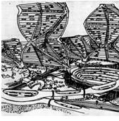
Floating city axonometric | 1:2,500 [i]
helix structure
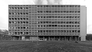
Unite d’habitation - Le Corbusier
“A seriously minded architect, looking at it as an architect, will find in a steamship his freedom from an agelong but contemptible enslavement to the past” [xxiv] Completed in 1952 in Marseille Corbusier beckoned in the era of modernism with (amongst others) his work on Unite d’Habitation using the steamship as inspiration for “An architecture pure, neat , clean and healthy” which in essence embodied the spirit of modernism. The iconic building draws closer the grounded with the floating by highlighting resemblance in operation, scale and intention. [xxiv]
Utilizing human proportions with its chunky pilotis and interior passages, it redefined high density housing by re-imagining a city within an 18 storey block.
The relevance of this project is in its reflection of the functional clarity embodied by a steamship and its operation as an autonomous modern floating city albeit temporarily.


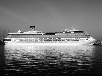
Shifting focus from infrastructural scale to small scale independent precedents, the intention behind their study is in identifying the requirements for low rise high density floating communities.
The following projects, some planned others organically developed, have the advantage of being constructed. This allows for a less theoretical discourse on the typology, and factors such as economic feasibility, practicality and construction method are brought to light.


A prefabricated floating community of lightweight steel modules developed by Rohmer Architects in Holland.
The units are organized parallel to one another and are moved into place by barges and boats but are themselves immobile.
Built on a series of basic modules, doors, windows and walls were flexibly inserted based on the needs of each individual home.
Their temperate setting dictates a highly glazed open feel. They are and are themselves immobile.
Unlike previous examples, the town utilizes common buildings located strategically to operate as services and community space for the occupied units.


Scarborough floating homes, Toronto, Canada Formal/Organized hydrological community
‘Float homes are full-time, year-round residences that are built on floating concrete barges. They are moored to a dock and anchored to the lake bed. There are no motors, nor are they designed to navigate. Float homes share the same luxuries as homes on land with heat, hydro, plumbing, a/c, 9ft ceilings and insulation.The Scarborough Bluff is located 15 minutes away from the city.’ [xxv] There is a 1250 gallon septic holding tank under the home that needs to be pumped out once every two months. [xxvi] These floating homes are similar to the formal Kelong communities but have developed as a luxury living arrangement rather than a necessity.
distribution diagram


Floating homes Lake Union, Seattle
Formal/Organized hydrological community
The result of landed properties reaching the waterfront and expanding onto it as a means of housing the growing population, the floating homes in Lake Union exhibit almost identical features as the homes on land.
Autonomously produced, the units that have varying docking heights which is compensated for by the informal pier allowing for access and movement to hard ground. Intended to be immobile and formal houses, they are built on concrete floats. The floats are either designed as inverted bowls over Styrofoam floats or act as floats themselves as hollow bowls. [xxvii]
The houses connect to the land based sewage and electrical network for operations. These houses are the realization of landed homes attempting to tackle water based living with the least amount of adaptation.


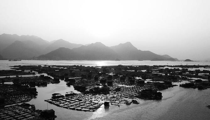

Floating village, Sandu’ Ao, China Informal hydrological community
Sandu’ao, also known as Future Water World, in China, is a floating fishing village where the inhabitants need not set foot on land as part of their daily lives. They have their own floating mail posts, police station, restaurants and convenience stores. As the largest community on the sea in China, most of the residents here earn a living by fishing and ocean farming. After a decade’s development after being devastated by Japanese aerial bombardment, it has again become the largest aqua cultivation base of yellow croakers and other seafood in China [xxviii]
Sandu’ao exhibits remarkable autonomy for a floating village with a lack of formal infrastructure and construction. Similar to other Chinese villages, Sandu’ao features simple houses constructed with wood or PVC, built on pontoons made of bamboo/wood. The pontoons are usually tied to barrels and pieces of PVC as flotation devices. [xxviii]
The village is strategically cut off from the open sea to prevent the threat of waves and storms destroying their intuitive infrastructure and housing.
The sea farming is carried out using thousands of cages and fishing nets attached to their infrastructure. Boats are utilized to navigate to and from land.
Sandu’ao’s autonomy arises from the simple and adaptable approach adopted by its residents.
Unit distribution diagram
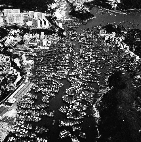

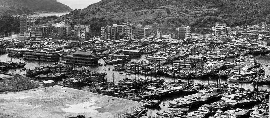
Aberdeen Harbour, Hong Kong
Informal hydrological community
Aberdeen harbor in Hong Kong is an informal hydrological community that utilizes the typhoon shelters within the harbor as a location for large scale parking of fishing vessels. Through the aggregation of these fishing boats, a community is created by virtue of the boats sharing a common deck height that allows mobility within the series of boats without the need for a formal pier.
Similar to Sandu’ao in China, its informality allows for its efficient functioning. The primary occupations of the dwellers is fishing and tourism. [xxix]
Boats detach themselves from the collective to either embark on a fishing trip or offer rides for tourists. The more mobile a boat is the further from the dock it tends to be located. Aberdeen’s aggregation pattern is efficient in its ability to operate as a singular unit as well as allowing individual boats freedom to operate. This typology can be adopted to autonomous floating communities.
Context
Precedent investigations scaling from massive infrastructural to tiny cluster aggregations and ranging from local to global examples, bring to light the varying attributes they exhibit in resolving problems novel to floating urbanisms. These attributes are to be selectively incorporated into the development of the project’s aggregation proposal
In order for the appropriate selection of attributes, it is important to first understand the context in which the project seeks to locate the aggregation (Singapore), its climate, weather, topography and currents. This will enable the choosing of two specific sites within the boundaries of Singapore within which to strategically tailor and deploy the aggregation. The inspection of Singapore begins with large scale territorial and topographical study eventually zooming into tide, climate and weather.
Singapore/Indonesia Border 1973-2006
Singapore/Malaysia Border 1927 - 1995 Country Baseline System
Malaysia/Indonesia Border 1969
In order to begin utilizing Singapore’s water as a resource for expansion, it is necessary to understand its place in the larger Sijori region as well as how Singapore utilizes its territorial water and coastline. The topography of Singapore’s coastal waters directs focus towards shallow, protected locales, which when combined with water current, existing anchorages and non-utilized coastline reveal possible sites for the aggregation scheme to be implemented.
A dense network of connectivity ties the Sijori region together. Within Singapore’s territorial waters, inter island connectivity is enabled by ferries, egPulau Ubin and the Sister Islands.
Anchorages | 1:250,000 [i]
Currently Singapore utilizes 10% of its land area in water for the purpose of anchorages and a large proportion of Singapore’s coastline is inaccessible to the public and utilized for various purposes.
The unavailability of the coastline limits possible sites for implementation which is exacerbated by its high density of anchorages and further by the lack of protection for the available coastline.


Singapore’s tidal oscillations vary through the months but as with all tide experiences 2 high and 2 low tides every day. The change in tide takes roughly 6 hours and shifts forward approximately 40 minutes to an hour every day. [xxxii]
Tidal movement has an impact on selecting a location based on the nature of the tide and current relationship. Ebb and flow of current intensifies at certain periods and at chokepoints caused by land infringement. This causes the current to move faster through these choke points making those locations unusable. [xxxiii]
The maximum water height difference Singapore experiences is roughly 3 meters. Any land based hydro-dwelling designed should have a pier system that can support a tide variance of approximately 3 meters if not more.
Water Current distribution - 2:30 pm [xxxi]
Water direction - towards east
Water Current distribution - 9:30 am[xxxi]
Water direction - towards west


Refocusing from territorial information to location specific climate - Singapore. Singapore has a tropical climate of hot and humid throughout the year averaging a temperature around 31º C during the day with little seasonal variation. [xxxvii]
The psychometric chart suggests that the temperature and humidity are too high for exposed activity to be comfortable. The solution is either artificial ventilation, achieving shade or a combination. Sitting just north of the equator, Singapore’s sun path is centered on the equator and vertically symmetric reducing seasonal variation of incident light. The primary concern is dealing with the eastern and western sun.


Singapore annual prevailing winds
South East Asia’s wind pattern brings in 2 seasonal monsoons. One from the North-east from December to march and one from the South-west from June to September. The consequence of the monsoons do not impact the design directly, rather indicate that the locations need to be prepared for storm surges and incorporate appropriate drainage systems.
Singapore monthly prevailing winds
Two locations are chosen within Singapore’s territorial waters exhibiting favourable features for the implementation of the aggregation scheme. The features include - shallow sea depth, lack of anchorages, unused coastline, low current, sheltered from rough seas, lack of tidal shift impact and lastly no transportation lines through the location.
Located between Johor and Singapore the island of Pulau Ubin and its offshore smaller island create a protected strait with low exposure to the currents. The topography is not uniform but does not exceed 15 meters in the selected cove.
It creates an enclosure large enough to implement a large scale proposal with little external interference

Site location sea current intensity
The second location is south-east of Singapore’s mainland next to Sentosa called St. Johns and Lazarus island.
The site is nestled in the small bay created by the southern part of the 2 islands capped above by a bridge.
The topography of the location is relatively undulating, reaching a depth of almost 20-25 meters at its deepest but with a gradual slope away from land.
The two islands together protect the bay from harsh currents moving above and below depending on tidal shifts.
Being further away from Singapore, it is affected more adversely by storms and tidal water level but remains within a manageable range.

Singapore’s tropical weather poses distinct challenges in dealing with the elements and their manipulation in achieving interior comfort without conforming to complete artifical ventilation.
The intention is to create an integrated system of natural and artifical ventilation that caters to programmatic requirements while retaining view and opennes in the unit.
Traditional tropical architecture utilized large pitched overhangs on low rise high density houses as a means of achieving climate appropriate architecture in creating shade, providing ventilation, and keeping rain out. These aspects exist both in bungalows as well as shop-houses with the roof being the primary architectural feature.
Having established two locations, and several of the components to be incorporated into the design and planning, the project attempts to tackle the issues specific to the project on a smaller scale, namely - weather, material, flotation device and appropriated imagery.


The invention of artificial ventilation has caused a shift towards the emulation of temperate architecture enabled by the hermetic disconnection of interior space from exterior realities of tropical climate. Architecture has in turn stopped dealing with issues that are intrinsically tropical in both high and low rise structures.
With the increase in Singapore’s density requirements, a low rise high density fabric is not sufficient and needs to expand vertically. This shifts architectural priority from the roof to the elevation or envelope which takes on the performance role in operating as the filter between interior and exterior.
Climatic operational primacy shifts from the roof to the elevation which wraps around the building as the density and height of the urban fabric increases making the elevation the primary location of architectural innovation and climate control. Shade, cross ventilation and a double skin can be utilized for both drainage as well as insulation from solar radiation.
The initial design for the hull structure was provided by Venturer Pte. Ltd. - a collaborating agent on the project. The hull is made of 6 mm mild steel and measures roughly 18 meters by 4.8 meters end to end. It is designed to be modular and can be dismantled and stored if necessary with a depth of 1.2 meters. The pieces can be assembled with ease and are waterproof independently as well as together.
The hull therefore dictated the original footprint of the unit that was to be developed which was 12 meters by 4 meters excluding the bow and stern and providing some leeway on either side for access.
The hull utilizes sponsons on either side which function as buffers between the steel frame and any docking mechanism as well as stabilizers if the superstructure extended beyond 2 storeys.


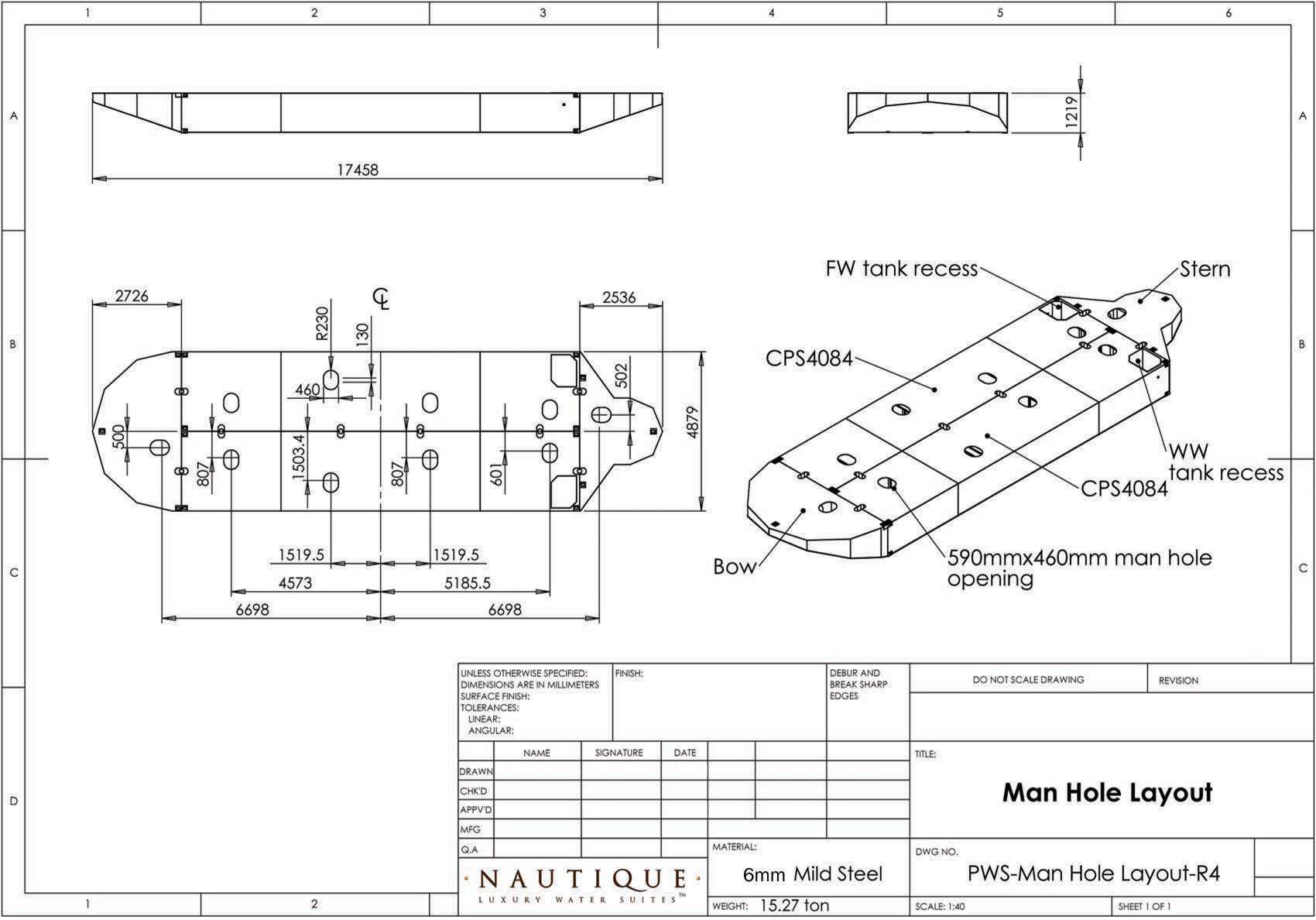
The original hull was modified with the intention of creating a larger footprint by utilizing the modular structure to combine 2 hulls together with a central spine piece. The result was essentially a 2 and a half hull structure. Due to the modularity of the hull, the reconfiguration was simple to design but required testing for nautical safety and certification.
The new structure provided a larger square floor plan of approximately 12 meters by 12 meters which allowed for more options in terms of the unit and its flexibility as well as aggregation strategies using the units.
The bow and stern received minor adjustments to appear less independent of one another. The overall structure allows for a broader, more stable base and a less narrow overall superstructure which could allowed for a wider applicability of the unit.
Both the single and double hull structures were developed to explore their potential and applicability fully.

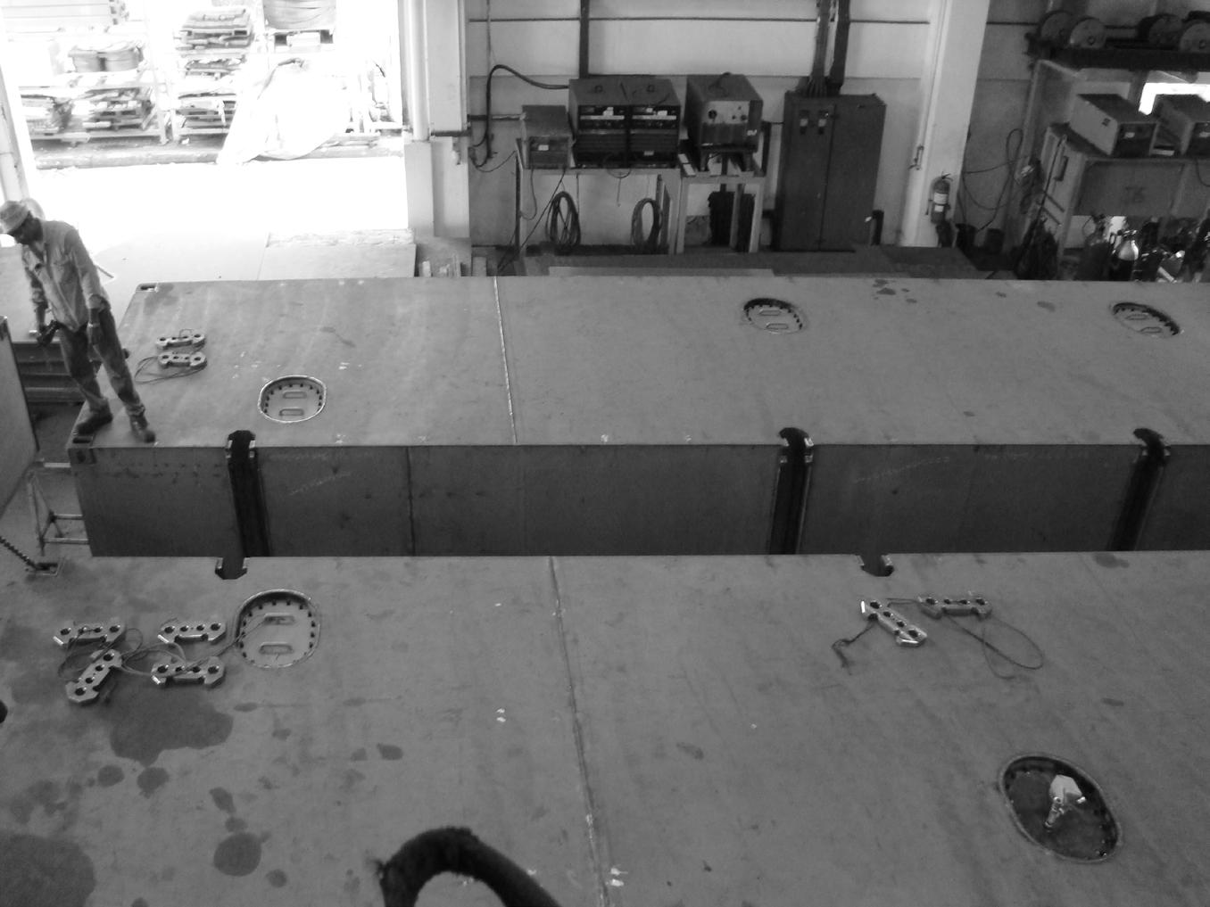


Bureau Veritas testing images of designed hull for structural soundness based on loading charts using custom developed software.

Testing conducted by Bureau Veritas based on general arrangement plan developed in the project including loading, stability, hydrostatics and KN curves. Full report included in Annex.


Cross Laminated Timber was chosen to be the primary building material of the superstructure of the floating unit due to its light weight, modularity, relative low cost and ease of construction reinforced by Venturer’s position as a timber supplier.
Cross Laminated Timber (CLT) is an engineered wood building system designed to complement light- and heavy-timber framing options. Part of a new product category known as massive (or “mass”) timber, it is made from several layers of limber boards, stacked crosswise (usually at 90 degree angles) and glued together on their wide faces. This cross lamination provides dimensional stability, strength and rigidity, which is what makes CLT a viable alternative to concrete, masonry and steel in many applications. It can be used for an entire building, as both the lateral and vertical load resisting system or for select elements such as the roof, floor or walls. [xl]
A CLT workshop organized by Venturer Pte Ltd in collaboration with NUS allowed for public outreach and exposure of the modularity, efficiency and ease of construction of CLT as a building material.
The workshop enabled the understanding of the material, its jointing and implementation on a real scale.
CLT, which requires weatherproofing treatment for external use is either cladded with Parklex or Thermowood if not painted over. Glulam is an alternative to CLT as a manufactured timber but differs in being unidirectional unlike CLT. Glulam is sometimes utilized due to its unidirectional strength in beams or when exposed wood is required.


Aggregation
The aggregation requires the establishment of primitives to be utilized and replicated to create aggregation options.
Each of the primitives retain the essential elements of their completed designs while doing away with unnecessary detail to aid in replication.
The development of the primitive is expressed later in full detail.
The single unit is divided into 3 corridors along its length on its lower floor with one of the corridors dedicated for public movement through the unit. The other 2 combine up to form the private spaces on the lower floor. Using the bow, stern and the public corridor within the unit, a network of public access is created through the series of single hull units.
The double hull unit, not requiring a private corridor, is linked through small extensions to the back or front that connect up as a public corridor while retaining privacy.
The above diagrams represent how the public corridor in the single hull alternate between left and right, thereby facilitating access in a ring or through some units.
Selected units in both the single or double hull aggregation are left unoccupied and cater to the service needs of the community.
Within an aggregation structure, specific units would necessarily have to be fixed in place while others are free to disconnect or relocate themselves. The fixed units, referred to as nodes, define the skeleton of the aggregation scheme along with piles or wiring that can be expanded upon by the addition of other units. It is favorable to ensure the service units and the fixed units coincide to maximise efficiency of accomodation
To establish a control, a regular pier is created with a height change capacity of 3 meters depending on tide.
The schemes begin with the simplest forms of aggregation which are almost land dependent, growing in complexity till they achieve a complexity sufficient to function autonomously.
Land based community Independent
A simple system of aggregation using the pier as a connecting device. The single and double units have their entrance in the rear allowing for an outward ocean view from the stern.
The pier can rise or fall with the tide enabled by the piles holding it in place. A maximum displacement of 3 meters is catered for.
Land based community Independent
Maximizing the pier length by using both sides allows for a higher density aggregation but is possible only in locations where the view is favorable on both sides.
Due to size, the double hull unit has a lower aggregation density than the single hull unit but represents a higher degree of luxury and openness. This openness poses concerns of privacy for the lower floor when aggregated which can hopefully be resolved in further aggregations.
Water based community Independent
The first step towards autonomy is the units disconnection from the pier. The most fundamental form of this is through the independent mooring of the units away from the pier.
The units exhibit no semblance of interconnectivity, co-dependence or mobility.
The main form of connection to land is through a dinghy or external boat.
This form of aggregation is closest to a the fishing villages in China (Sandu’ao) where the infrastructure enables the hydrological community rather than the units themselves.
Land based community
Co-dependent
Diverting from independent to co-dependent aggregation, the system here presents an option for co-dependence through a parallel connection between units. Privacy is a concern for both the unit types but this solution pushes towards a more independent solution than the last.
Due to the open lower floor of the double hull unit, the privacy concerns are a bit more warranted.
The pier is connected on the two ends and is utilized to provide a connection from the rear communal walkway to land.
Land based community
Co-dependent
In order to solve the obvious concerns of privacy and closeness of the units, a radial aggregation is adopted. This solution retains the rear walkway while spacing the units out in their stern, providing novel views to each.
A suggestion of independence is created while retaining a co-dependent aggregation structure.
The fixed units
As mentioned, the privacy concerns of the double hull unit are somewhat resolved through this radial arrangement.
These systems are still land based in being connected to the pier and dependent on the structure it provides.
Water based community Co-dependent Simple organization
Combining the developed systems of co-dependence and water based aggregation gives rise to the double radial aggregation.
Using a single chain of double or single hull units and linking their public access corridors we create a co dependent water based hydrological network. The access to land is through an external boat.
Water based community Co-dependent
This system is the expansion of the radial system which switches directions to prevent from forming a closed loop and ending the possibility for expansion. The aggregation can be made tighter or looser depending on when the direction changes and how many units are in each radial aggregation.
The fixed unit at the center of the aggregation facilitates the change in direction by being a communal unit which allows users to walk through.
This form of aggregation is similar for both the double and single hull structure with the only difference coming from the radius suggested by the size of the unit varying.
What the system does lack is the ability to cordon off space for fishing or other aqua-cultural purposes which is an important prerequisite in a hydrological system.
The access to land is through an external boat although units can disconnect and move over themselves if needed.
Water based community
Co-dependent
Complex organization
Water based community
Co-dependent
Complex organization
As the organization grows in structuring, scale and unit count, the generated internal space allows for the aggregation to function as an independent self sufficient cluster. Incorporating these models into the aggregation scheme allow for maximum density but a slightly lower flexibility.
The various aggregation models are placed within their potential site to better understand scale and functioning in the specific location.
The various aggregation models are placed within their potential site to better understand scale and functioning in the specific location.

The above schemes are developed to provide a starting point for the aggregation by using a single module to achieve the desired density of a small town of 1500-2000 people within the site chosen. However, the project in seeking to develop a more organic system incorporating various kinds of smaller aggregation pieces diverts from this strategy and simply uses it as contrast to help ensure the density can be achieved within the site. The density and eclectic nature of Collage city by Colin Rowe and Fred Koetter is used as precedent for the scheme to work towards and achieve in coagulation of the smaller aggregation pieces.
Possible aggregation strategies in Pulau Ubin using a single aggregation module
Given the tubular nature of the site, navigation becomes a key criterion for the organization of the aggregation system.
In order to facilitate mobility within the scheme while retaining density, various typologies are combined to create interior walkways with sufficient buffer distance between them for units to disconnect from the system at certain locations. The center of the scheme is intended to be fixe din place primarily with little to no change.
This creates a hierarchy of formality increasing towards the center of the system with the extremities housing the service and replaceable units while the centre hosting the communal and more residential spaces of the system.
St. Johns Island bay offers a much broader site which allows the scheme to expand across the area.
It divides itself into two based on the smaller and larger bay sections created by the topography.
The hierarchy in this system is incremental away from the bay i.e progressively more formal units towards the land/bridge areas.
This allows for the outer units to be more mobile and disconnect to restock or for transport purposes.
Both schemes make use of an collage esque approach to the aggregation with a base logic of mobility, spacing, thoroughfare and hierarchy while remaining organic in its organization.
Sample of aggregation scheme in Pulau Ubin within its topographical context


Day render


Night render

A prorotype was developed for a single hull unit using the hull profile of the existing Nautilus 55’ built for Venturer Pte. Ltd.
The initial prototypes were developed by students under Erik L’Heureux as part of a catalogue to be used for marketing purposes by Venturer in order to interest potential investors.
The designs from the catalogue were absorbed was then passed onto the research team at NUS to develop and investigate as part of a research project in floating houses.
Iteration I
The evolution of the single hull prototype are detailed along with diagrammatic representation.
Iteration II
The development of the unit was primarily focused on the functioning of the lower and upper floors as an open public space and a private living quarters respectively. The profile of the unit was changed from a double tube with the circulation on the exterior to reading as a single volume with the circulation on the interiors and the sides capped with two large walls..
Eventually a longitudinal division of the unit into 3 parts was incorporated to try and build into the prototype a system for public circulation while keeping the lower floor as private as possible.
Iteration IV
Iteration V
The division of the interior into 3 started to shape the unit on the lower floor and roof while keeping the second floor unaffected and meant to read as singular.
The big walls were fitted with a porous panel with a herringbone pattern to reduce thermal load and provide a drainage gap. The wall has a ribbon window which opens looking down to the water.
The primary views from the upper and lower floor are focused towards the front and back with the ribbon window providing some view out of the sides.
The final scheme includes a roof pitch to help drainage while resolving the longitudinal division on the interior and exterior. The double skin is utilized where applicable with the roof using a timber decking to reduce thermal load as well.


The above axonometrics describe the initial framework developed for the superstructure on the
The framework represents the intentions of the spaces within the floating suite rather than their actual form.
A light highly porous lower structure supports a more private upper volume open to the views and punctured by skylights.
model iterations I - IV
Screening options


The above axonometrics describe the initial framework developed for the superstructure on the double hull raft.
The framework represents the intentions of the spaces within the floating suite rather than their actual form.
A light highly porous lower structure supports a more private upper volume open to the views and punctured by skylights.


The above axonometrics describe the initial framework developed for the superstructure on the double hull raft. The framework represents the intentions of the spaces within the floating suite rather than their actual form.
A light highly porous lower structure supports a more pirvate upper volume open to the views and punctured by skylights.
Skylight geometry and interior screening
Solid rear lower floor with solar panels on roof
Iteration V
Iteration VI
Iteration VIII model images
The development of the module for the double hull takes the form of axonometric 3D modeling as well as planar interior changes.
Each iteration that is documented contains one or more impactful ‘moves’ that change the project and attempt to resolve a problem.
A screen is utilized to create privacy in the upper story while functioning as a climatic filter between inside and out without disrupting the view.
The screen and the screening system is developed in tandem with the overall design and the intention is to achieve a singular synthesized product.
The skylights and screen are cycled through several iterations to try and optimize their aesthetic and performative roles.
The roof is fitted with solar panels intended to handle the units electrical load. The surface area utilized is based on the requirements for a landed house of similar size. A generator is installed as a backup and placed within the upper floor M&E space.


The models are fitted with potential screening options. The goal is to allow for viws outwards while reducing thermal load ang screening from rain.
The long vertical slit is CNC milled out of a panel as a groove which deepens till it cuts through the volume.
The size of the opening is varied across the surface of the screen based on the program underneath that portion of the screen.
The long vertical strip was seen as less than ideal for rain screening amongst other factors and was thus discarded.


Exploded axonometric Exploded axonometric
Two systems were considered for the screening and volume of the upper structure - one tube and one drape.
The drapw screened over the upper floor akin to a piece of cloth being draped over and the tube allowed the screen to wrap around the upper floor disconnecting it volumetrically from the lower floor.
Finally the drape was chosen for its tropical relevance, its flexibility and its ability to convey the principles embodied by the project.


A parametric system was incorporated to variegate the perforations in the screen option introduced in the following iterations. The intention was to reflect the privacy/openness of the interior by reducing or increasing respectively the perforations in those regions. The result was a rough v shape over the span of the screening system on both sides.
Screening option
Screening option
The screen for the unit was treated as a fabric intended to drape over the unit and create a roof pitch for drainage. The screen remains porous on the roof allowing rain to flow through and is later drained off the roof with a pitch This function of the screen as a double skin above the interior roof reduces thermal load and cools the unit.
Rhino pattern simulation for perforations
Grasshopper logic for pattern simulation
Grasshopper logic for solar radiation simulation - Ladybug and Honeybee

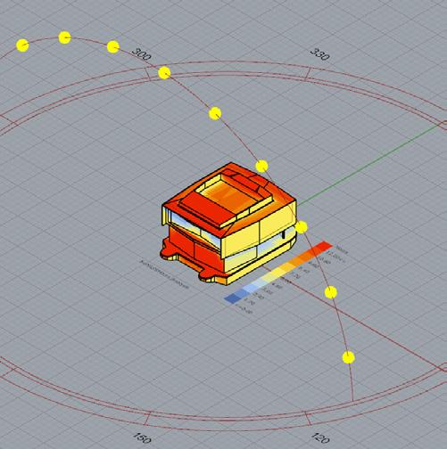


The climatic calibration of the unit was achieved through parametric iteration and testing . The roof access was detailed with skylights that were tweaked to minimize solar gains. Similarly, the depth of overhangs, solar exposure of glazing and setbacks were all redesigned based on the results of the testing.
This iteration incorporated a pitch in the roof to try and solve certain issues of drainage as well as create more interior headroom for the upper floor.
The ambition of making the roof accessible is reflected in the change in skylight geometry to try and accommodate an entry point and create a decking space with a railing in the form of geometric intervention.
The roof proved to be one of the most challenging aspects of the project.
It required the incorporation of a full height access, a cordoned off space for the deck, the skylights and a bar counter and seating all the while remaining aesthetically in tune with the rest of the structure.
Several iterations were cycled through.


Through the simplification of the roof structure and the shift from a full height access to a hatch, the roof volume was closer to resolution than previous iterations. The screen was developed as a single ‘membrane’ to bend and drape over the entire volume of the project as if a piece of cloth.
A taper was introduced in the screen on the rear side elevation to match its functional overhang and to create a stronger directionality.


A mild pitch in the roof structure was introduced to allow for drainage and ensure the skylight glass remained stagnation free.
The structure was further simplified to ensure coherent elevations from the front and side. The glass for the skylights were set in deeper into the structure based on the simulations done to determine solar incident and heat load.


A collaborative design meeting involving NUS, Venturer and Bureau Veritas was conducted to modify the superstrucutre, its load bearing members, dimensions and overhangs to adhere to CLT capabilities and ensure structural soundness of the floating suite.
Various minor changes were incorporated as a means to resolve the material or spatial restrictions imposed by CLT.
Structural axonometrics were iterated through to determine the best structural system to be utilized given the unique material - CLT - to be utilized in the project. Several consults with Venturer Pte. Ltd resulted in one solution to be refined upon revision.
Collaborative reworking of CLT structure between NUS and Venturer
Overall isometric with screen


