10 minute read
The road to H2


Justin Ellrich and Carina Winters, Black & Veatch Corporation, USA, explain the role of LNG technology in the hydrogen transition.

The pledges made by companies and countries across the globe to decarbonise have accelerated plans to adopt hydrogen as a fuel source. However, significant development time and investment remain for transportation infrastructure and production volumes to enable widespread hydrogen use with economical access for end users making the transition. While this full build-out of a hydrogen economy is a decade or more in the future, steps are being taken in the interim to introduce hydrogen into the clean fuel mix which has most recently been led by a boom in natural gas. The current infrastructure in place and the technologies employed to process, transport, and use natural gas will play a major role in ramping up the mix of hydrogen in fuel supplies. This article focuses on two specific aspects where hydrogen and natural gas overlap: pipelines and liquefaction.
Until more dedicated hydrogen pipelines are constructed and combustion equipment is converted or replaced with pure hydrogen-firing capability, hydrogen will likely be blended into natural gas up to the limitations of the existing pipelines and equipment. As hydrogen blending increases, so too will the list of LNG plants that get supplied from


blended pipelines which will need to make modifications to enable continued operation. Where pipelines are not available, compressed hydrogen can be transported in cylinders, but volume and distance limitations exist with this method to remain economical. Much like the proliferation of the global LNG trade, liquid hydrogen is poised to grow to allow producers to ship to consumers across greater distances.
Hydrogen blends feeding LNG facilities
Potential incompatibility of metallurgy and compression equipment for existing natural gas pipelines will limit the concentration of hydrogen transported in existing infrastructure, expected to be between 15 - 20% maximum. Various scenarios have been proposed to be served by this blending, with the leading candidates being a lower carbon content for existing natural gas consumers or as a carrier with separation of hydrogen at the take-off point for further use. Either scenario presents a challenge to LNG facilities that are connected to one of these blended pipelines in the future, particularly peak shavers that are used to store natural gas in liquid form for later use during high demand periods. While utility companies may begin to source hydrogen along with natural gas, there will still be a need for reliable back-up supply, and the most mature path to accomplish this is the existing LNG plants already used for such a purpose.
When a hydrogen-natural gas blend is used as feed gas to an LNG facility, the hydrogen will remain as a vapour at LNG temperature, so flash gas handling and overall plant capacity will be impacted. However, the refrigeration system can remain as-is while retrofits in ancillary components and new equipment can be implemented to retain functionality of LNG production while also separating a concentrated hydrogen stream. The hydrogen can be re-injected into the pipeline, used as zero-emission on-site fuel when burners are modified, or fed downstream to a new user where higher purity hydrogen is needed.
There is already proof and precedent of the processing schemes necessary to handle hydrogen with LNG. Black & Veatch has patented two designs that are employed in currently operating facilities using a single mixed refrigerant system to co-produce LNG and hydrogen rich offgas from a mixed feed stream created by upstream processes. In one configuration, two fractionation columns achieve the required separation. In the second configuration, a single column with a small nitrogen refrigeration system for the condenser duty is necessary to reach the desired specifications.

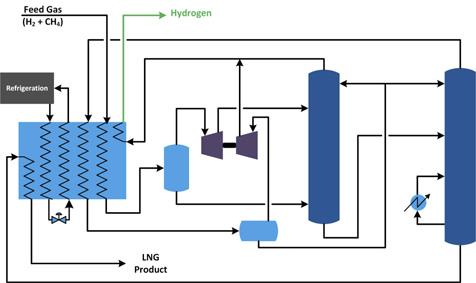
Figure 1. Two-column system for hydrogen/natural gas separation.
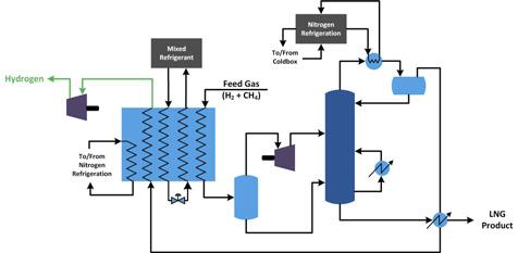
Figure 2. Nitrogen trim refrigeration system for hydrogen/ natural gas separation.

Two-column system
The proper selection of separation technology will depend on the hydrogen concentration in the feed stream, the required hydrogen-rich gas specification, and must consider any other components besides methane and hydrogen in the feed. Luckily, the most likely scenario will be a blend of pure hydrogen up to 15 - 20% in pipeline quality natural gas which will be the simplest design, particularly for a retrofit. And if the hydrogen is to be re-injected into the pipeline or used on-site as fuel, hydrocarbons can remain at low levels in the offgas which will reduce overall duty for the separation process.
This set of circumstances is a candidate for the twocolumn fractionation system as shown in Figure 1. Exiting the cold box, the hydrogen-rich vapour is separated and let down in pressure by a turboexpander to feed the absorber column. Reflux further removes the hydrocarbon traces from the hydrogen-rich gas which can then be used in downstream or other on-site applications. The methane-rich bottoms stream from the absorber is sent to the second column for further separation. The overhead product of the second column is partially condensed in the main cold box. The liquid portion is used as reflux in both columns and the lighter vapour portion is compressed and combined with the first column overhead product. The bottoms product of the second column is the LNG product, which is subcooled in the main cold box before going to storage.
The operating reference for this design processes approximately 21 mol.% hydrogen and 70 mol.% methane, with the balance of nitrogen. Methane in the hydrogen-rich gas can be reduced to 0.5 mol.% to maximise LNG production and limit downstream processing of the hydrogen stream. The pipeline blending situations will have lower nitrogen content which will significantly lower reboiler duty to meet LNG specification as well as lowering reflux as the hydrogen-methane separation K-value is very high. Other variations of this scheme are possible depending on feed gas concentrations and more relaxed outlet specifications – consolidation to a single tower, or even elimination of the towers if the turboexpander outlet or initial flash stream with a few percent of methane is acceptable as the product.
Nitrogen trim system
Another possible configuration for hydrogen-methane separation is a single column configuration with a nitrogen refrigeration cycle for the condenser duty. The scheme in Figure 2 is tailored for higher hydrogen content (up to 60%) and can also handle significant carbon monoxide if the feed stream is sourced from an upstream syngas process. To meet tight hydrocarbon-in-offgas specifications for feed streams with high concentrations of lighter than methane components, a colder equilibrium temperature below approximately -180˚C must be achieved. This is below typical LNG temperature so additional refrigeration is required to supplement the standard LNG-only refrigeration design.
Just like the two-column system, the two-phase stream exiting the main exchanger will be separated and the vapour drives a turboexpander to feed the fractionator. The fractionator can meet less than 0.5 mol.% methane in the overhead as well as less than 0.5 mol.% CO in the LNG product. The supplemental nitrogen refrigeration utilises a compressor so the nitrogen condenses at LNG temperature exiting the main exchanger, then reduces pressure as required to meet the colder reflux requirement. More heat integration can be accomplished by adding an additional exchanger which simultaneously warms the hydrogen product, subcools the LNG product, and subcools the nitrogen refrigerant. While this system may not be as common of a need for pipeline blending, other hydrogen production scenarios with gasification or reforming could potentially use this configuration for LNG co-production or to supplement membrane or PSA separation units depending on specifications and dispositions of the various offgases.
Pre-cooling for hydrogen liquefaction
Hydrogen and natural gas liquefaction have similarities, though the additional 100˚C of cooling needed for liquid hydrogen limits the machinery and refrigerant cycles that can be employed. But getting hydrogen down to typical LNG temperatures before further refrigeration can be achieved by the same technology used now for natural gas, and approximately 15% of the total duty of hydrogen liquefaction comes from this pre-cooling step.
One of the major barriers to widespread adoption of liquid hydrogen supply chains is the cost of liquefaction. Past and ongoing research has identified a number of improvements to hydrogen liquefaction cycles because the efficiency of common systems in operation today is not considered adequate for scale-up in terms of meeting economical cost targets. In terms of the pre-cooling portion, liquid nitrogen is employed on a small scale but is clearly not viable due to cost and logistics for large scale operations. The focus of many researchers has been the use of closed-loop refrigeration cycles to increase efficiency and lower production cost for this step. But these cycles need no new development, they are simply what is used for LNG and can be directly implemented at any scale with known performance and little risk.
Moreover, while the focus is on scaling up of the hydrogen liquefaction process, the closed-loop pre-cooler is akin to small scale LNG. Even at 100 tpd of hydrogen liquefaction, which would be world scale, the equivalent size of the pre-cooling cycle would be of that seen for 0.1 - 0.2 million tpy of LNG production. Black & Veatch’s PRICO single mixed refrigerant offers vast experience in this size range with standardised components. The increase of efficiency over closed-loop nitrogen cycles, along with reduction in complexity compared to multi-loop processes, results in an optimal balance of capital and operating cost reduction to aid in reducing overall liquid hydrogen production cost.
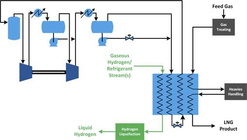
Because the pre-cooling cycle can be basically the same process used for natural gas liquefaction, there is opportunity for integration in projects that may be developing co-located natural gas and hydrogen infrastructure, even for a retrofit. Figure 3 shows a schematic for integration of hydrogen pre-cooling and natural gas liquefaction, which is as simple as the addition of dedicated passes in the main exchanger for the product and refrigerant pre-cooling streams but otherwise maintains the same operating principles for LNG.

Figure 3. Integration of natural gas liquefaction for hydrogen pre-cooling.
Summary
The hydrogen transition is a major pathway necessary for decarbonisation, but natural gas infrastructure will remain a critical piece of the low-carbon energy mix until the considerable investment and project development timeline for zero-GHG fuels can supply the needs of the world. But hydrogen and natural gas should not be mutually exclusive, and significant integration of these fuels can provide a short-term benefit while working towards the long-term goal.
The sharing of natural gas pipelines is possible which brings challenges to LNG facilities potentially subjected to new blended feed gas, but proven designs already exist that can be applied as greenfield solutions or as retrofits to maximise use of existing assets to simultaneously handle hydrogen and methane. It is also easy to draw corollaries between LNG and hydrogen liquefaction, and the overlapping segment of pre-cooling can directly apply LNG refrigeration technology to reduce production costs.
Even as demands for both the type and state of fuels changes over time and new schemes are developed to enable wider hydrogen usage, the underlying process technologies currently used in the LNG market can be leveraged and applied in multiple ways to hydrogen to accelerate companies toward their net-zero goals while remaining reliable and cost-effective for their customers.


