11 minute read
Improving drilling performance through drill bit hydration
Duncan McAllister, Karl Rose and Mike Ott, Varel Energy Solutions, USA, and
Sebastien Reboul, Varel Energy Solutions, UAE, consider the experiments and modelling used to identify the key elements of a PDC bit design centred on drill bit hydration.
Optimising hydraulic energy at the drill bit has been a goal for many years. Managing the total flow area (TFA) of a set of nozzles is based on pressure drop needs as well as the ability to pass material, such as lost circulation material (LCM), through the bit. Over time, nozzles have been manipulated to be longer, apply a curved vector to the exit and be directed in towards a specific location. With PDC bits, as rig capacity continues to increase, so more and more hydraulic energy is being produced through flow rate and pressure. To take advantage of that energy, advanced learning around how to apply the current generation of curved nozzles, along with matching a set of PDC design criteria, allows for improved bit cleaning, cuttings evacuation from the face of cutters and improved cutter cooling. This article will discuss Varel Energy Solutions’ (VES) methodology around drill bit hydration.
Building on knowledge
When VES first launched the HYDRATM design philosophy, development on how to best apply the techniques continued. HYDRA attributes are centred on solving problems specific to optimising PDC bit hydraulics. It provides a way of critically looking at all the factors that influence performance while finding the optimal balance of features using the rig’s available hydraulic energy.
R&D based on this design philosophy resulted in fresh insights into fluid flow patterns at the cutters and around the bit body.
These insights led to experiments with different bit design scenarios and the development of a distinct set of design features. These features make up a system that is balanced to optimise hydraulic energy for the application.
System features
The HYDRA solution applies three bit features: Ì Curved nozzle. Ì Webbed blades. Ì Straight blades.
Curved nozzle Webbed blades
HYDRA design bits have a webbed blade feature that connects each secondary blade to the back of a primary blade to help contain and direct hydraulic force for optimised cleaning and evacuation. Conventional PDC bit designs typically leave this space open. By blocking off the flow path between blade junk slots, it forces the fluid coming out of each jet to remain in the junk slot. This significantly enhances the amount of fluid flowing across the cutter faces. Without them, fluid can be forced to flow into an adjacent junk slot, thus potentially starving a set of cutters of needed flow rate.
The curved nozzle is a feature that continues to see successful runs on standard bit designs as well. With the HYDRA design, it is coupled with blade and bit geometry features to improve the use of the rig’s available hydraulic energy. Curved nozzle geometry has evolved over time to allow more efficient flow paths and to incorporate a new method for nozzle installation. This has Straight blades
Figure 1. Hydraulic shear stress modelling.
Straight blades, in comparison to conventional curved blades, enhance hydraulic performance by increasing cutter cleaning and cooling. When the blades are not straight, the fluid is forced to travel further to access the cutter faces. Since the shortest distance between two points is a straight line, a straight bladed bit gives the most direct access for the cutters (especially on the shoulder of the bit) to the directed flow coming from curved nozzles.
A study was developed with the aim of improving hydraulics performance to increase rate of penetration (ROP) compared to current bit models. Multiple computational fluid dynamics (CFD) studies identified two key variables contributing to PDC bit hydraulic performance: shear stress and cutting evacuation.
Based on this information, various bit designs were modelled to identify the best package of attributes. The model scenarios examined various configurations of blades (straight, spiral and webbed) and nozzles (curved and conventional).


The studies showed that greater hydraulic shear stress across the face of the cutters and front of the blades improves cutter cleaning and cooling. In doing this, the position of the curved nozzle – particularly its azimuth and nozzle exit points – is an important variable.
Efficient cuttings evacuation depends on quickly and effectively moving cuttings away from the bit and into the annulus. Studies showed that blade geometry has the biggest effect on cuttings evacuation. Straight blades showed a significant increase in cutting volume.
Hydraulic shear stress modelling provided significant insights into how fluid moves across the cutters and blade face. Each bit configuration was modelled and compared to a non-HYDRA standard bit.
In Figure 1, the bit blade is shown in dark blue and shear stress is indicated by the lighter colours. The standard blade model shows hydraulic shear stress confined largely to one section of the blade. However, modelling of the test blade shows shear stress reaching a larger area of the blade and cutters. Greater shear stress is indicated further down the blade (circled area) and higher up the blade, providing a much greater area of cleaning and cooling.
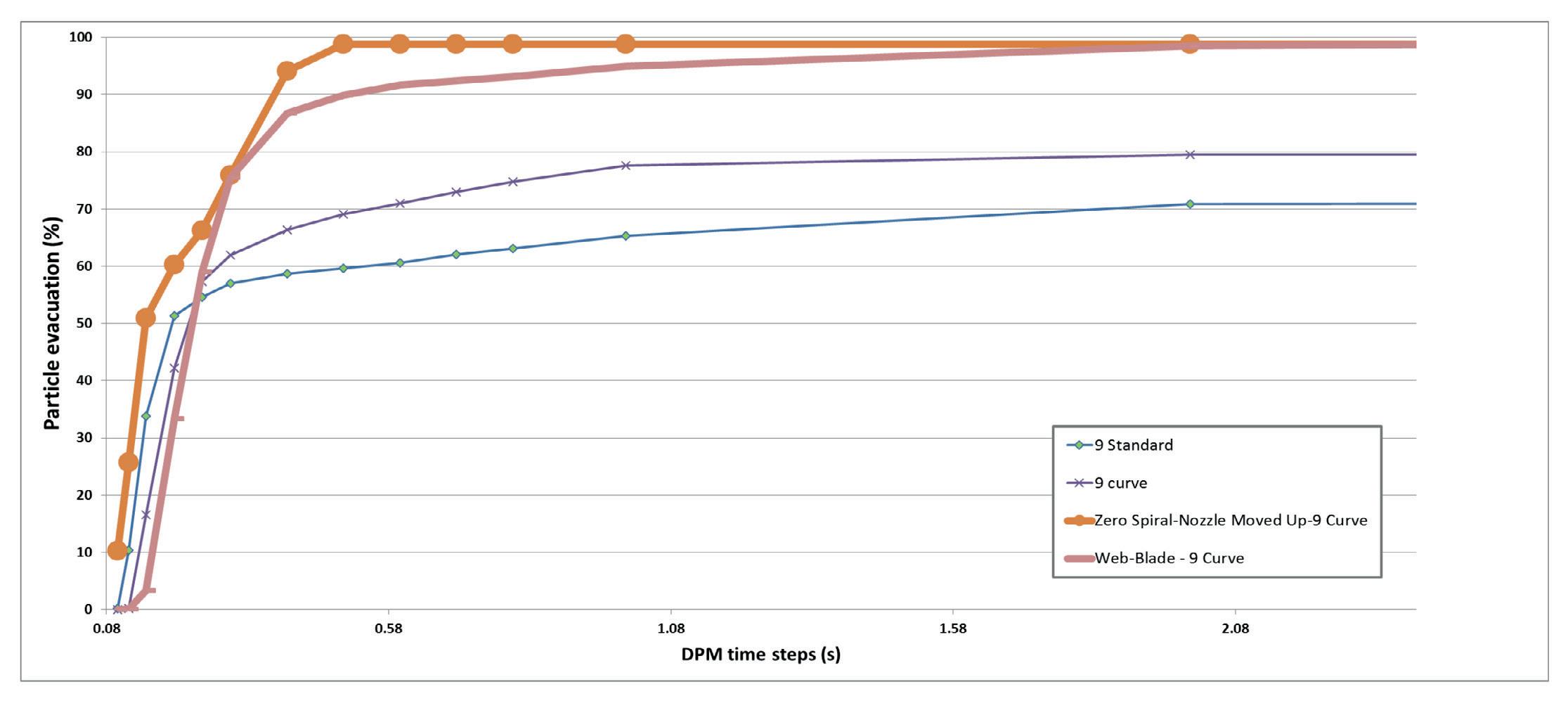
Cutting evacuation for various bit model scenarios were plotted using a VES technique to measure and compare cuttings evacuation. Optimally, the cuttings quickly leave the cutter and travel quickly through the slots and into the annulus.
In Figure 2, a plot of time versus the percentage of particle evacuation shows how long it takes to move cuttings into the wellbore annulus.
The modelled process determines the time it takes for a set number of cutting particles generated at the cutter surface to move through the junk slot and into the annulus. Cutting generation is simulated at the contact point between the edge of the cutter and the formation. Particle model interaction with fluid flow and its transport time to the annulus is calculated. The particles are then individually introduced to the model and their transport is measured over time to determine a percent evacuation time.
The various bit models exhibited a wide range of particle evacuation, from 70% to 100% (Figure 2). The best performance was from a zero-spiral model that had a steep evacuation rate that reached its peak very quickly.
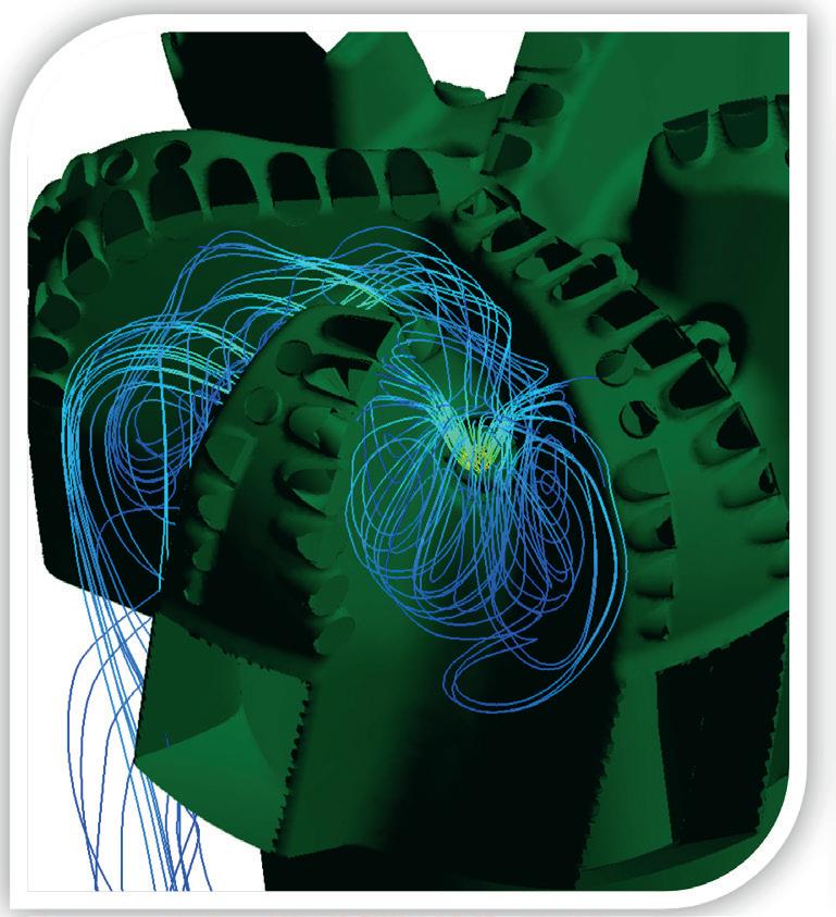
A ranking system was used to compare hydraulic shear stress and cuttings evacuation for the various models. Taking the curve out of the blades was a key factor. The top three models for shear stress were all zero-spiral blades. In terms of cutting evacuation, the number one rank was the webbed blade model, which had nine curved nozzles. Adding the webs significantly improved cuttings evacuation. When the webs were used with non-spiral blades, cuttings evacuation was enhanced. This analysis revealed the three key elements of a HYDRA design bit: webbed blades, nozzles and straight blades. Webbed blades The analysis was significant in showing the degree to which cuttings are re-circulated with conventional open blade designs, and revealed a marked difference in how standard and webbed blade designs affect fluid flow. With standard blades, particle movement was localised around the blades in the primary and secondary junk slots, but did not exit the junk slots. Adding the webbing cut off the flow path around the blades, to help direct cuttings flow out the junk slot (FIgure 3). Figure 3. Webflow. Conventional (left) and HYDRA (right). Figure 4. Nozzleflow. Conventional (left) and HYDRA (right).
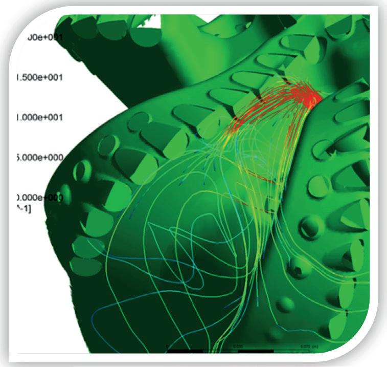
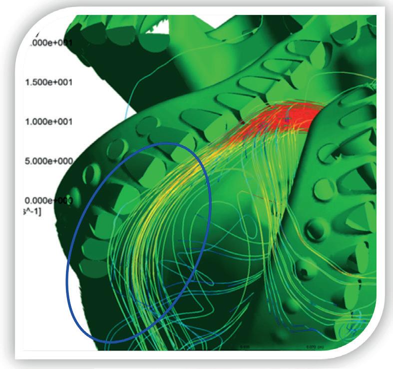
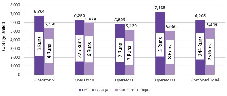
Figure 5. HYDRA versus Standard – STACK vertical section footage comparison.
Figure 6. 16 in. Oman top-hole HYDRA footage and ROP comparison versus competition.
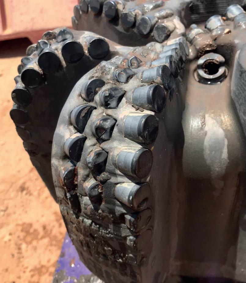
Figure 7. 12 1/4 in. Oman dull picture with HYDRA.
The impact of a curved nozzle with regards to cutter cleaning and cutter cooling is significant. It directs greater shear stress across the face of the cutters, and results in more complete cuttings evacuation.
Flow models clearly show the curved nozzle produces a strong flow line running across the base of the cutters, and in front of the blade to push cuttings down the junk slot and into the annulus. This is in strong contrast to the conventional nozzle, where flow is much less organised and is restricted in its reach (Figure 4).
Straight blades
The three top ranking scores were all bits that had straight blades, because straight blades have more hydraulic shear stress further down the blade. This improves cutter cleaning and cooling, because the nozzle exit is closer to the actual element, in front of the blade and the cutters.
Field performance
To date Varel has successfully deployed HYDRA technology in 5000+ bit runs across the globe. This continued pursuit of applying the technology’s design philosophy to the applications has also resulted in recent successful runs in demanding intervals.
Mid-Continent field data
HYDRA designs have been successfully utilised in Mid-Continent, US, applications for the past 4 years. The first part of the wellbore that the design showed an impact on performance was in the intermediate section in the STACK region. The technology’s success in this application can be attributed to an improvement in cutter cooling and cuttings evacuation, leading to improved cutter life that in turn results in longer bit runs and better dulls. In an analysis of 269 bit runs in the 8.75 in. vertical ‘drill out’ section across four STACK operators, HYDRA-equipped bits showed a 17% improvement in average footage drilled as well as an average dull grade improvement. The bits maintained an average dull grade of 1.1 – 2.2 (inner – outer) compared to 1.6 – 3.7 (inner – outer) for standard designs. The additional durability that HYDRA-equipped bits provided in this application also led to an increased reliability to make it to total depth (TD) in one run. The bits made it to TD in one run 89% of the time, compared to standard PDC bits that made it 40% of the time (Figure 5).

An expanded use of the HYDRA features has made an impact in many other applications where hydraulic efficiency plays a key role in bit performance. Most recently, an operator in Oklahoma, US, drilled a challenging lateral section. This section is a medium to high compressive strength interval with mixed amounts of heavy minerals, where it is not uncommon to see dulls that are damaged beyond repair.
When drilling through these abrasive zones with variable compressive strengths it is important to maintain hydraulic efficiency through the shale sections while maximising cutter cooling in the abrasive zones. An 8.75 in. HAVOX-613 with HYDRA was able to drill the entire lateral at 63 ft/hr, which set a new benchmark for the operator.
Oman field data
HYDRA designs have been successfully deployed into operations in Oman to cover several applications.
In one application, in shallower wells, the top-hole section is experiencing an increased ROP in 16 in. bits when being drilled with motor performance bottomhole assemblies (BHAs). By allowing better and faster cuttings evacuation at the cutter to rock interface, increases have been realised. This has resulted in optimum efficiency while drilling out relatively soft shale with a base carbonate formation.
The jetting action of the curved nozzles, combined with the webbed blade configuration to prevent any cross flow and cutting recirculation, delivered ROPs with a 45% improvement over the average ROP of the best offset runs and an almost 15% increase over the best run to date (Figure 6).
In another deep and very challenging 12 ¼ in. section, HYDRA increased bit durability (Figure 7). This was achieved by directing the fluid directly to the key location of the cutter/rock interface to target the area that has the highest cutter wear rate. This further highlights one of the main advantages of the HYDRA concept.
Bringing the fluid directly to the key location of the cutters/rock interface with the curve nozzle (and especially towards the shoulder of the cutting structure, where the highest diamond wear is usually seen) is one of the main advantages of the HYDRA concept.
Diamond wear is directly linked to the heat generated and volume of rock removed, which is typically highest on the outer portion of a bit, hence the benefit of cooling down this area by increasing flow distribution. This will slow down the cutter wear and prolong bit life in challenging, long section applications.
The 12 1/4 in. VION-616 was used for a challenging 2000 m section to drill into an interbedded formation sequence that includes a shale, carbonate and sandstone formation.
It drilled the full section to TD at an average of 30 m/hr, improving the usual ROP achievement by at least 15% due to a sharper cutter throughout the end of the run.
Conclusion
As more projects take place with new concepts being applied, the learnings will continue to grow. It has been shown that using the available hydraulic energy in the drill string can be directed into an efficient pattern around the bit that that results in incremental drilling value. For Varel Energy Solutions, this is defined as drill bit “hydration”.

Never miss an issue


Receive the latest issue of Oilfi eld Technology straight to your inbox

