
10 minute read
Cleaner Conveyors
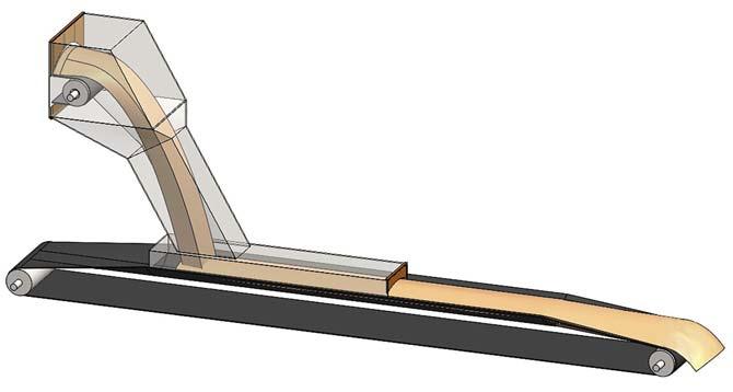
Several variables were investigated to simplify the analysis. The complete conveyor with discharge and receiving belts was modelled and, while there were significant regions of recirculation in the upper discharge section, the air flow in the chute was reasonably consistent. The chute was thus simplified to that shown in Figure 3, with the air volume and dust particles injected into the last 2 m of the chute.
The combination of variables studied are given in Table 1. Both external and internal analyses were conducted, with complete moving discharge and receiving conveyors (Figure 4). The bulk material surface was set to absorb particles and the walls set to reflect particles. The eff ectiveness of the enclosure variations was determined by counting the number of each size of particles that escaped the end of the enclosure compared to the number injected.
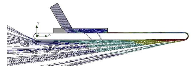
The results of the external analysis indicated that escaped dust particles increased in speed, as the air current is aff ected by travelling around the belt and the discharge pulley. This phenomenon is known as the Magnus Eff ect and emphasises the need for eff ective belt cleaning as close to the discharge as possible. A space of 1 mm between the bottom of the skirtboard and the belt was used to simulate leakage.
Figure 1. Theoretical dust particle settling distance ‘L’ in skirtboard enclosure.
Figure 2. Model of complete standard conveyor receiving and discharge for external analysis.
Figure 3. The standard conveyor used for baseline internal analysis.
Figure 4. Typical external analysis results – dust particle trajectories.
Curtain designs

Several experienced maintenance technicians were surveyed and their preferred curtain arrangements modelled. In addition, multiple curtain designs and placement schemes were studied, including staggered, slit, curved, angled, with and without slits, with holes, and no curtains. Several unconventional skirtboard enclosures were modelled in an attempt to create recirculation in the enclosure and improve dust settling (Figure 5). The optimum design for the standard conveyor was determined to be a conventional enclosure with a height of 600 mm a length of 3.6 m and three dust curtains placed in defined locations (Figure 6).
Worn exit curtains were also modelled, and as the spacing above the load increased, the dust settling performance deteriorated. The use of a single curtain right at the exit proved problematic in all cases, acting to speed up the exit air flow even further when close to the belt and re-entraining dust in the exiting air stream, while being ineff ective in creating recirculation within the enclosure. When the curtain placed at the exit was worn too much, it was as if there was no curtain at all. A curtain placed right at the exit and adjusted close to the load creates another fugitive material problem, sometimes called the popcorn eff ect, where the curtain causes spillage by knocking material off the belt.
Results
Particle density
Solid density had little eff ect on the settling of nuisance dust particles from 100 - 25 μm. In every case, 100% of the 100 and 40 μm particles settled almost immediately. As the bulk density increased, there was a moderate reduction in respirable dust emissions.
Discharge chute and tailbox
The junction between the discharge chute and the skirtboards was found to be an important design detail for creating recirculation. Making the width of the discharge chute narrower than the width of the skirtboard helps to fold the air flow going into the first curtain, and that encourages distribution of the air flow toward the top of the enclosure, rather than along the surface of the material. The retrofit and mitered junctions were significantly more eff ective than a simple butt connection and 300 mm height, as shown in the standard conveyor Figure 3.
The tail box had little eff ect on dust emissions out of the exit end of the skirtboards. In most configurations, the height of the tail box was set at 300 mm. The tail box length was set at 600 mm to match the typical 600 mm idler spacing used in the load zone by most conveyor manufacturers and engineers
Length of skirtboard
It was found that for most situations, a 3600 mm long skirtboard produced the best results. Increasing the length to 4800 mm and height to 900 mm had some marginal eff ect, but may not be worth the extra investment.
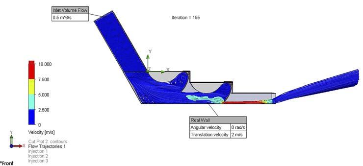
Figure 5. Example of one of the unconventional chute designs analysed.
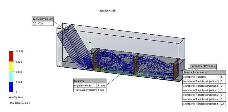
Figure 6. Typical recirculation air flow results with three curtains.
An enclosure height beyond 600 mm for the standard conveyor with a single exit curtain did reduce nuisance emissions, but tended to increase respirable dust discharge. This is due to the average settling path being greater with the higher enclosure.
Air flow
As would be expected, the average air velocity through the skirtboards was directly proportional to the induced air flow and cross-sectional area. Average velocities in the skirtboards due to induced air ranged from 0.8 – 2.8 m/sec. Belt speed had a minor eff ect on the average velocities. The maximum air velocities were almost always found where the air flowed under the skirtboard curtains. These high air speeds kept the respirable dust suspended, so reducing induced air into the chute was also shown to be important to improving performance.
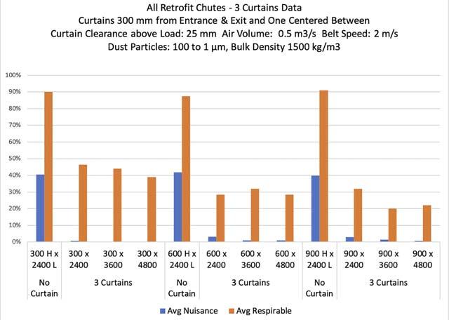
Figure 7. Summary of results – percent of dust particles exiting the enclosures. Curtains
The best results were obtained with three or more curtains (Figure 7). The design of the slits in the curtains is important to allow air to pass through, allowing the airflow paths to fill the entire chamber and not just flow at high speeds under the curtains. It was found that the individual flaps should be approximately 50 mm wide, with slits at least 5 mm wide and the curtains extending the full width of the enclosure.
Preferred embodiments
The best value for the cost of the skirtboard enclosure and its effectiveness is judged as skirtboards 600 mm high and 3600 mm long, with three full width slit curtains using either the retrofit or mitered discharge chute-to-skirtboard connection (Figures 8 and 9).
Table 1. Variables used in the particle study
Parameter Standard conveyor Experiment variables Belt speed (m/sec.) 2 2 – 8 Belt width 1200 600, 1200, and 1800 Bulk material solid density 1500 750, 1500, and 3000 (kg/m3) Air flow (m3/sec.) 0.5 0.25, 0.5, and 0.75 Curtain placements 1 at exit 1 to 6 curtains, at various spacings Curtain clearance (mm) 50 0 – 150 above load Skirtboard height (mm) 300 300, 600, and 900 Skirtboard length (mm) 2400 2400, 3600, and 4800 Wall roughness (mm) 1 0 – 100 Chute to skirtboard Standard inline Miltered, full width, and 90˚ Tail box length: 600 mm 300 high 300, 600, and 900 high
Dust particle dia. (μm) All configurations modelled with 100, 50, 40, 25, 10, and 1 μm dust particles Design recommendations
Design recommendations include: Discharge chute width across skirtboards 200 mm < width between skirtboards. Skirtboard outside width based on horizontal dimension of free belt edge for sealing and belt wander edge allowance ≥ 115 mm per side (FoundationsTM method). Skirtboard height ≥ 600 mm. Inlet to skirtboards air volume flow ≤ 0.50 m3/sec. Length of skirtboards for material loading turbulence ≥ 1000 mm when required. Length of skirtboards for dust settlement ≥ 3600 mm, plus extra allowance for loading turbulence if necessary. Skirtboard dust curtains: Entrance (1st) curtain 300 mm past end of extra allowance for material turbulence and distributing air flow. 2nd (middle) curtain centred between entrance and exit curtains. Exit (3rd) curtain 300 mm from end of skirtboards. Curtain clearance above the bulk material: 25 mm preferred, 50 mm max.
Curtain flaps: approximately 50 mm wide strips separated by slots ≥ 5mm.
Conclusion
While some improvement is seen with increased skirtboard height and length, it is doubtful that it can be economically justified on the reduction of respirable dust alone. A return on investment for control of nuisance dust for new and retrofit designs can be based on reducing cleaning labour, increased equipment life, and/or elimination of dust collection. If the improvements reduce the TWA of respirable dust emissions to the point where engineering or administrative controls can be less stringent, then a financial case could also be made based on improvements in labour productivity.
References
1. JOHNSON, A.T., ‘Respirator masks protect health but impact performance: a review,’ Journal of Biological
Engineering, Vol. 10, No. 4 (2016), https://jbioleng. biomedcentral.com/articles/10.1186/s13036-016-0025-4 [Accessed 1/14/21]. 2. SWINDERMAN, T., 'Foundations, The Practical Resource for
Cleaner, Safer, More Productive Dust & Material Control',
Martin Engineering, 4th edition, (2009). 3. 'Foundations for Conveyor Safety, The Global Best
Practices Resource for Safer Bulk Material Handling',
Martin Engineering, 1st edition, (2016). Figure 8. Recommended mitered skirtboard enclosure for new construction.
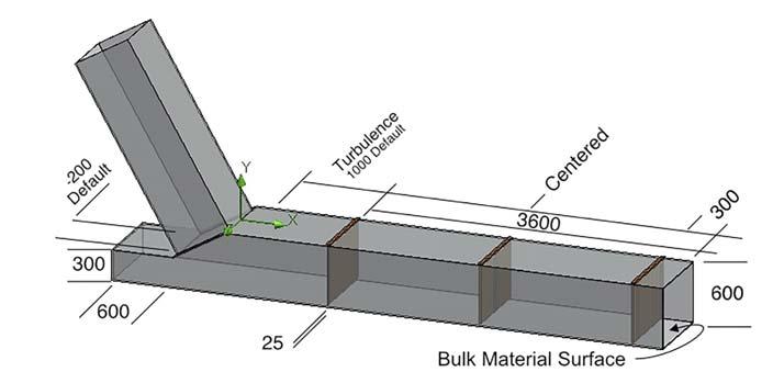
Figure 9. Recommended skirtboard enclosure for retrofit or angle transfer.

Global Mining Review App

Register to read the latest issue on the go!
Download the free app for Apple and Android devices:


Franco Mazzucato, VAREYE, Switzerland, demonstrates how the concept of chain of custody can help satisfy all of the main requirements of coal producers.



Corporate responsibility is a wide concept, encompassing the social responsibility of companies, as well as environmental friendliness, trade fairness, and much more. A novel stream adding to that is the concept of chain of custody (CoC), as more and more end-users get passionate about knowing that the products that they purchase derive from sustainable sources.
Several systems for the certification of CoCs have developed over the last few years and off er an array of services, sometimes based on the data security level provided by blockchain technology.
This article analyses the features of the VAREYE CoC and operational control system, using a case study to reference the short journey of coal from the mine through some transportation, warehousing, and transformation processes required to ship anthracite in diff erent grades ready for shipment to specific end-customers globally.

Background

The anthracite production process considered for this article is relatively simple; the raw coal is ‘simply’ extracted, by various means, from the ground and either deposited on huge fields for further shipment or directly sent, oft en via conveyor belts, to the subsequent process stage – a refinery. Some processes to remove impurities can include: washing with water; removal of ashes, ground, stones, and sulfur; crushing and pulverisation; screening from coarse to fines; agglomeration; and blending.
Although the full story is slightly more complicated, it is enough to help understand the position at each stage of the coal journey.
A certifi ed chain of custody for coal
A coal producer looking for a system to prove to their customers the true origin of the coal that they were selling also needed a flexible system to match, from the operating standpoint, exactly the kind of processes carried out within the perimeter of the mine. This was in addition to the refinery and tools to optimise the output from their facility, producing several millions of tonnes of coal per year. They decided to test and adopt the VAREYE system.


