11 minute read
An Individual Approach
Organised service teams that can take action in the locations where the equipment is operated. Provision of access to original spare parts.
Case study: Lignite mine, Bulgaria
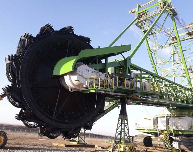
An example demonstrating full competence on the side of standard, as well as highly customised gear technology, is the delivery of gears for the KWK-2000 and KWK-400L lignite bucket-wheel excavators put into operation in 2019 at the Mini Marica Iztok EAD lignite mine (Figure 1).
The technical design and production of both excavators was carried out under the internal cooperation of FAMUR, FAMUR FAMAK and SKW Projekt, forming part of TDJ.
Structural designs of new bucket-wheel drive gears and designs of worm-epicyclic gears used in the driving and rotating system were developed at FAMUR Institute – a company belonging to the FAMUR Group, specialising in the development and implementation of new equipment and technologies.
Figure 1. Construction site of the KWK-2000 excavator. Designing the bucket-wheel drive gear
Conceptual work began with the adoption of design assumptions in December 2016. The basic construction assumptions for the bucket-wheel drive gear of the KWK-2000 excavator were developed by SKW Projekt (Table 1). An additional requirement that influenced the final design of the gear was the need to support the bucket-wheel shaft on the bearings of the gearbox’s planetary carrier. This meant that the gear design, particularly the gear body and planetary carrier, had Table 1. Basic construction assumptions for the FBWG 1000 bucket-wheel drive gear of the KWK-2000 excavator to transfer loads from the weight, as well as the mining Parameters Value forces of the bucket wheel, to the excavator arm. Rated output (kW) 1000 The entire process of Input shaft speed (rpm) 1000 creating the structural design of the FBWG 1000 Overall gear ratio transmission 238 (approximately) gear included: Total weight (t) <38 The development of a Bearing rating life (h) >50 000 conceptual design. Strength calculations. Permissible longtitudinal inclination of the gear (˚) -17 – 12 Bearing durability calculations. Forced lubrication system The development of a Lubrication method with dupicated pump system and drive independent of the kinematic gear train preliminary structural design. FEM strength analyses. Oil filtration Duplex pressure filter Modal analyses. Maximum oil temperature (˚C) 80 CFD numerical thermal analyses. Ambient temperature (˚C) -25 – 45 The advanced modules of the software packages used enabled the optimisation of the stress distribution on the teeth (Figure 2). This was accomplished with tooth line modification. The magnitude of the modification is assumed
Diagnostic system enabling
Oil heating system for low ambient temperature conditions Permissible sound power level LWA according to EN ISO 9614-2 [db(A)] The measurment of bearing temperatures, oil temperature, pressures in the forced oil circulation system, oil flow rate, oil flow indication and vibration acquisition, and monitoring Electric heaters built into the gear oil compartment
<104
with respect to the calculated shaft deflections and gear body deformations. Due to the demands concerning the sound power level, the geometry of the toothing was optimised on the level of both macro and micro-geometries. At the macro-geometry level, the contact ratio of gears, reference profiles, and tooth line angles are optimised. On the other hand, at the micro-geometry level, modifications are made to the tooth head and foot. The introduction of these modifications was made possible thanks to the numerical analysis of the contact in the gears meshing while simulating full gear load.
The non-standard way of supporting the gear and its weight restrictions resulted in the necessity of conducting strength calculations as early as the conceptual design stage (Figure 3). One of the most important design decisions was to determine the plane in which the main body division of the angle-cylindrical part of the gearbox occurs. Due to the large size of the components and the associated potential assembly problems, the concept of division by the gear axes was adopted.
In addition to strength calculations, analyses were conducted to verify the accuracy of the oil heating system used. The calculations required the simulation of conditions replicating the minimum ambient temperature and typical wind conditions that occur at the premises of the gear recipient. A separate scenario was created to simulate the dissipation of heat generated in the gears meshing and bearings via the casing walls.
Gear production
The production of the gears was conducted in a plant specialising in precise processing, located in Katowice, Poland, which was put into operation in 2010. In addition to the mechanical processing unit, there is also a heat treatment department (Figure 4). The mechanical processing unit conducts processing processes, including: Milling. Turning. Drilling. Surface and diameter grinding. Precise toothing processing on milling machines and tooth grinders manufactured by Gleason.
An important part of the production process is quality control and the use of lean manufacturing. Critical parts are inspected using ZEISS coordinate measuring machines.
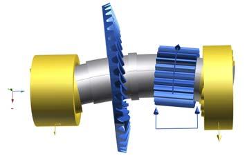
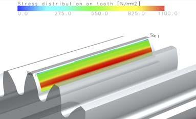
Figure 2. Shaft deformation analysis and results of optimisation of stress distribution along the tooth line.
Figure 3. Stress distribution in the gear casing.

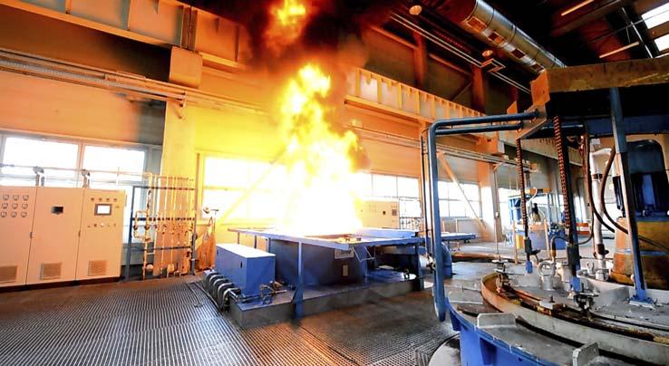
Figure 4. FAMUR heat treatment department.
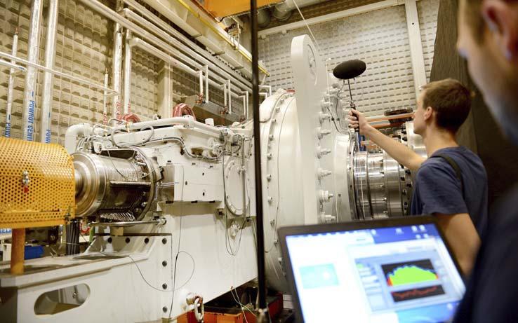
Figure 5. FBWG 1000 gear unit on test stand during sound power level assessment.
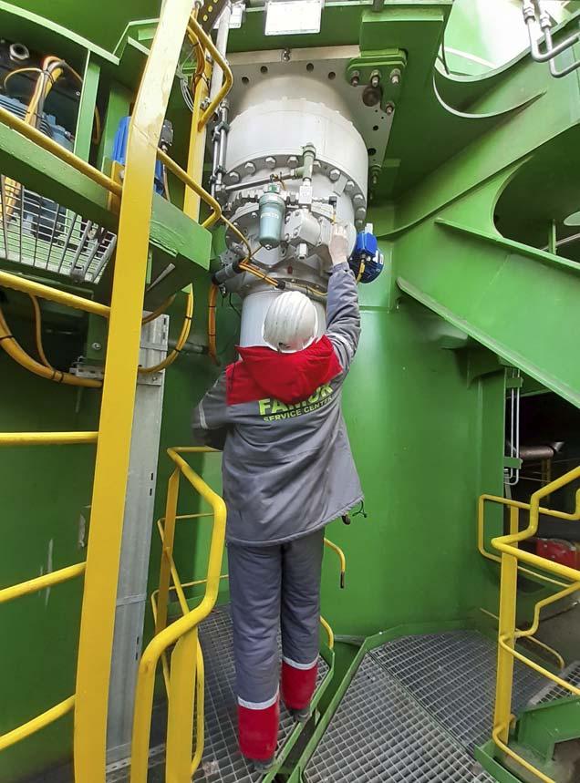
Figure 6. Service activities carried out by an employee of the FAMUR Group Service Center on the KWK-2000 rotation gear of the KWK-2000 excavator arm.
Gear testing
The customer required the supplier to test the gear under load and check the sound power emission level. It was possible to conduct these tests thanks to a specialised test stand with continuous power of 1.8 MW and instantaneous power of 2.7 MW, owned by FAMUR Group.
The drives are controlled by a set of frequency converters with power return to the electricity distribution network, making it possible to control the rotational speed and load smoothly. One of the operating modes that can be set during testing is the impact mode. In this mode, the torque varies between ±30% of the preset torque with a frequency of 10 Hz. The equipment of the test stand enables the performance of a variety of tests. The closed cooling water circuit means it is possible to test cooling systems equipped with heat exchangers. The data acquisition system allows for the linking of the signals from the built-in sensors on the devices tested with the parameters of the test stand control system. During the tests related to the sound power measurement, the drive motors are enclosed to eliminate unnecessary noise sources (Figure 5).
Keep Updated
Installing on a target device
One of the final stages of the life cycle is the delivery and installation of the gear on the target device (Figure 6). In the case of bucket-wheel lignite excavators, this task is particularly complicated and requires both experience and technical knowledge.
In addition to assembly and service activities, the FAMUR Group Service Center conducts activities in the field of remote diagnostics of the condition of machines. With this in mind, the FBWG 1000 gear was equipped with a diagnostic system that collects and transmits signals from sensors installed on the gear to the excavator control system. It also acquires and transfers the signals to the FAMUR RSIMS Predictive Maintenance system. This enables the presentation of the operating parameters of the monitored devices, as well as the automation of processes associated with the detection of malfunctions, based on measurements of temperatures, vibrations, loads, and pressures in the forced lubrication installation.
Conclusion
The experience gained from the design, production, testing, and, above all, supervised operation stages will pay off in future projects, where a high degree of adjustment of the design to the requirements and solutions used by the customer will be required.
Keep up to date with us to hear Keep up to date the latest in with us to hear coal news the latest in For more news visit: coal news www.worldcoal.com For more news visit: www.worldcoal.com


In part one of a two-part article, Dr Andrew Vince, Elsa Consulting Group, Australia, demonstrates how coal preparation plants can obtain money for ‘nothing’ through incremental accounting, incremental ash equalisation, and near gravity capture.


Once dug, raw coal is typically processed in a coal preparation plant (CPP) to remove rocks and dirt in order to allow tight product coal quality specifications to be met to satisfy premium priced market demands. These relate to the proportion of ash, termed ash value, that is formed when the coal is combusted. It is an undesirable characteristic with specifications for metallurgical coal markets of around 10%, and typically higher (>20%) for non-metallurgical products.
The proportion that is recovered by a CPP is termed yield and is expressed as a percentage. Higher prices are associated with lower product ash values and lower yields, and lower prices are associated with higher product ash levels and higher yields.
The CPP is only one of the processes in the mine coal production chain which can involve underground and/or surface operations. In the surface mining context, typical operations involve overburden removal, mining, crushing, and coal preparation components.
The approximate coal production cost breakdown for typical surface and underground mines is believed to be such that approximately 85% of the cost is incurred prior to the CPP. In other words, only around 15% of the cost is incurred by the CPP. Given that without the CPP highpriced coal product sales could seldom be achieved, such considerations dramatically magnify the economic importance of the CPP.

Incremental accounting concept

If the CPP performs better than expected, there will be extra saleable coal, which can be considered incremental saleable coal. Therefore, more money is made simply by increasing yield from the same quantity of raw mined coal. The incremental saleable coal can also be considered to eff ectively incur rejects handling/disposal credits as less has to be dumped. The 15% incremental production cost only comprises costs relating to processing, reject, and product handling.
When the plant performs better than expected, extra product is generated, as if by magic, at very low incremental cost.

Table 1. Hypothetical mine cost structure Cost Item Breakdown (%) US$/product t Overburden removal 65 19.50 Coal mining 20 6 Crushing and processing 15 4.50 Overall 100 30
Table 2. Hypothetical mine total and incremental accounting outcomes
Basis Total Incremental Selling price (US$/t) 50 50 Cost (US$/t) 30 4.50 Profit margin (US$/t) 20 45.50 % profit margin 40 91 To provide a hypothetical numerical example, based on the cost structure shown by Table 1, Table 2 provides a very simplified financial comparison of total and incremental accounting analyses.
It is very revealing that a profit margin of 40% more than doubles to 91% when considered on an incremental accounting basis. Additional yield therefore creates significant leverage, and every extra tonne of product generated by yield increase from the CPP has an equally significant incremental financial benefit. In the Table 3 example, a hypothetical CPP with a feed rate of 1000 tph is considered. It is initially able to achieve a 60% yield, but this is increased to 61% by CPP improvements. The net result is US$3.6 million additional annual profit. However, on the other hand, a decrease to 59% yield, reduces annual profit by US$1.5 million.
In summary, additional yield in the CPP achieves additional sales revenue at very low incremental cost. The corollary is that yield loss in the CPP is expensive to the mine.
Typical CPP process
Table 3. Hypothetical incremental revenue change for 1% point CPP yield change
Yield in CPP Feed (tph) 1000 1000 1000 Yield (%) 60 61 59 Product (tph) 600 610 590 Profit (US$/h) 12 000 12 455 11 800 Incremental profit change per 1% yield increase 455 -200 (US$/h) Annualised incremental profit (assume 90% 3 587 220 -1 576 800 availability) (US$)
Figure 1. Schematic of a CPP circuit. CPP processing separates product with metallurgical uses in iron and steel production that typically commands the highest prices. In particular, coal used to make coke is required to exhibit combinations of value in use properties that are quite rare, and the same is true of the coke so produced.
Some of the rare and valuable properties relate to the propensity of the coal to cake and coke when heated anaerobically in a coke oven, and occur if significant proportions of vitrinite maceral are present.
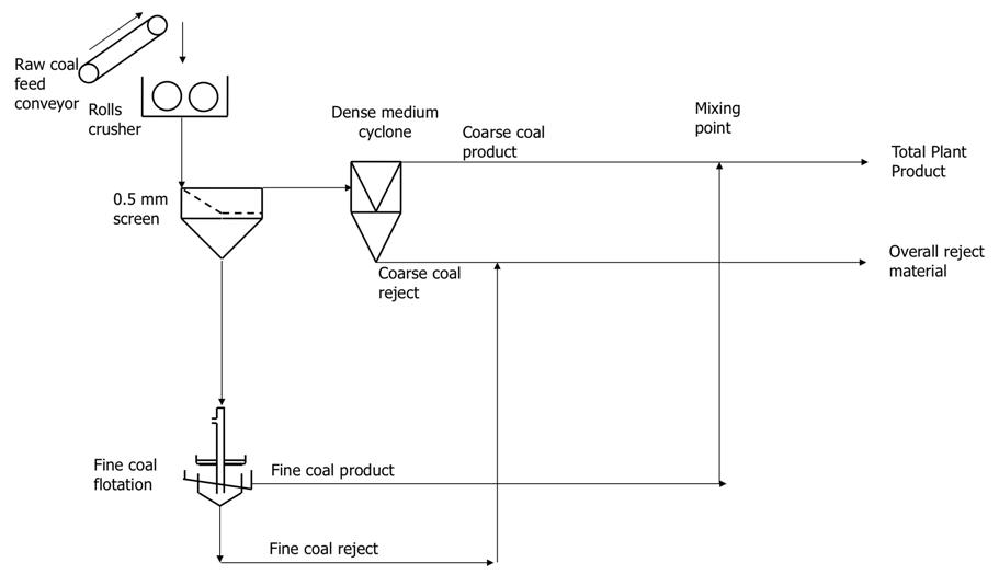
A typical older style CPP circuit processing coking coal is depicted in Figure 1, where an initial size separation at 0.5 mm is shown. Here, dense medium cyclone (DMC) technology is used to beneficiate the coarse fraction, and fine coal flotation (FCF) technology used to beneficiate the finer material. The total plant product (TPP) is generated by combining the coarse coal product (CCP) from the DMC, and the fine coal product (FCP) from FCF unit. To properly analyse the performance of a CPP from a metallurgical context, it is necessary to consider imperfect operation of each equipment item. In this process, the raw coal passes through a screen which separates particles greater than 0.5 mm in size, and so generates coarse and fine streams. The coarse stream, assumed to be 75% of the raw coal feed, passes to a DMC unit that separates ostensively on particle density, with light material reporting to the overflow and the heavier rejects passing to underflow. The fine stream, in this instance assumed to be 25% of the raw coal feed, passes to the FCF unit in which
