
14 minute read
Wireless signal transmission through hermetic walls in nuclear reactors


Jerry Potts b , Yuan Gao, Heng Ban a a Multiscale Thermophysics Laboratory, b Department of Mechanical Engineering and Materials Science University of Pittsburgh, PA, USA
Jerry Potts is from Bensalem, Pennsylvania and is currently pursuing a Bachelor’s degree in Mechanical Engineering with a minor in physics. He has worked as a research assistant in the Multiscale Thermophysics Lab under Dr. Heng Ban since January of 2019. He plans to continue his continue his education by pursuing a Ph.D. in Mechanical Engineering with a focus in clean energy systems. Jerry Potts
Heng Ban
Dr. Heng Ban is the R.K. Mellon Professor in Energy at the University of Pittsburgh. He is the head of the Multiscale Thermophysics Lab, whose research includes developing novel techniques for measuring thermophysical properties at the micro-scale, as well as in-pile instrumentation to study nuclear fuels and materials.
Significance Statement
Using wired sensors in nuclear reactors leads to extremely high costs and downtime for maintenance. Wireless sensors are a promising solution, but can have difficulty operating in a radiative environment. This study seeks to verify wireless inductive transmission as an alternative and indicates it could be a viable method.
Category: Device design Keywords: Wireless signal transmission, inductive coupling, LVDT, nuclear reactor
Abstract
Nuclear reactors rely on traditional wired sensors for fuel and system monitoring. As wireless technology becomes more developed, it could potentially be a reliable workaround to the issues of maintaining wired sensors. However, many methods of wireless signal transmission are unable to operate properly in the harsh environment of the reactor. This paper assesses the viability of the use of near-field inductive coupling as an alternative wireless transmission method to measure fuel parameters in a nuclear reactor. A prototype was developed where wireless inductive coupling was used to supply power to a linear variable differential transformer (LVDT), which can be used to measure various fuel parameters, and to then record the output of the system. These tests were primarily concerned with the linearity, uncertainty, and repeatability of the measurements. Further testing was then conducted to observe if the wireless transmission would be able to penetrate the cladding of a nuclear fuel rod. The resulting data indicated that the measurements were highly repeatable and had a very strong linearity throughout the experiment. There was, however, a considerable increase in the uncertainty of the system.
1. Introduction
Equipment and fuel monitoring in nuclear reactors currently depend on hundreds of various sensors. The installation of these sensors can be very costly and lead to significant system downtime due to maintenance [1]. Wireless sensors can serve as a cheaper, more reliable option to the wired sensors that are currently used. These sensors are able to circumvent issues such as feedthroughs penetrating pressure barriers, corrosion, and other forms of cable degradation [2]. However, due to the harsh radiative environment of a nuclear reactor, the system needs to be encased in stainless steel cladding in order to protect the sensor components. So, any wireless sensors developed need a signal strong enough to penetrate its own cladding as well as the cladding of the fuel, neutron moderators, and potentially the wall of the reactor itself. This greatly limits the available methods of wireless transmission which can be used in this application.
However, near-field inductive coupling can serve as a high efficiency wireless transmission mechanism for in-pile measurements of fuel parameters [3]. The tight electromagnetic coupling of the inductor pair maximizes the mutual inductance of the two coils and would allow the signal to penetrate the stainlesssteel cladding of the fuel rod. The ability of a signal to pass through a material can be quantified by that material’s skin depth, or the distance through a material at which the signal strength has decayed by a factor of e. For metals the skin depth is on the scale of micrometers, but the exact value is inversely proportional to the square root of the signal’s frequency [4]. So, by minimizing the operating frequency of the sensor the skin depth of the cladding will increase and limit the signal decay. This also ensures the sensor can be contained in its own cladding to avoid exposure to the reactor coolant and minimize the impact of external noise from the radiative environment without preventing signal transmission.
The purpose of this project was to design a system to assess the validity and accuracy of signal transmission using wireless inductive coupling. The system was designed around the use of a linear variable differential transformer (LVDT) as the sensing mechanism. An LVDT was selected for this system as it was already proven to be able to withstand the harsh environment of a nuclear reactor during the Halden Reactor Project [5]. Thus, using an LVDT makes this wireless system more applicable to short-term applications in reactors. If this prototype is successful, a new prototype will be developed using the same setup in order to further examine the signal transfer in more reactor-like conditions.
2. Methods 2.1 Theoretical Model of Wireless Signal Transfer
Mutual inductance occurs when an alternating current in a coil induces a voltage across the ends of adjacent coils via its changing magnetic field. The strength of the mutual inductance depends on the spatial relationship between the two inductors, namely distance and orientation. This mechanism can be modeled using the equivalent circuit shown in Figure 1 [6]. (3)
For signal transfer, we need to model a second set of coils to transfer the output of the LVDT out of the circuit. The system can be modeled such that the LVDT circuit is the primary circuit providing the source voltage and the secondary circuit consists solely of the inductor coil L 2 . By doing so, the above equations can be rearranged to determine the output voltage from the wireless signal transfer, as shown in Equation 4.
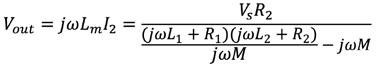
(4)
2.2 Experimental Setup
Using the theoretical models described in section 2.1, an experimental prototype was designed to verify the inductive coupling. The electrical model of this system is presented in Figure 2.


Figure 1: An equivalent circuit showing the principle of mutual inductance.
By applying Kirchhoff’s voltage law to this system, we can derive equations to represent the coupling of these circuits as shown in Equations 1 and 2.
(1)

(2)
Where L 1 , R 1 , and I 1 refer to the inductance, resistance, and current of the primary circuit respectively and L 2 , R 2 , and I 2 are the inductance, resistance, and current of the secondary circuit. V s refers to the supply voltage, ω refers to the system frequency, M is the mutual inductance between coils L 1 and L 2 , and L m is the inductance of the LVDT. These equations can then be used to quantify wireless signal transfer as well as power transfer, both of which are used in this prototype. To supply power to the prototype, Equations 1 and 2 can be used to calculate the voltage across the LVDT—which is represented as the voltage drop across the inductor L m in Figure 1—and the required source voltage, as shown in Equation 3.
82 Undergraduate Research at the Swanson School of Engineering Figure 2: Electrical model of the prototype.
The AC power source is used to provide power to the LVDT through the first set of inductor coils. Then, the output of the LVDT is transferred to a third circuit through another set of coils and read out via a multimeter. The LVDT used in this system is an HR500 from TE Connectivity. The core displacement ranges from 0 to 25.4 mm with a maximum non-linearity of 0.25%. This corresponds to a maximum uncertainty of 32 µm for the core displacement.

A physical model of system in shown in Figure 3a and is color-coded to better understand the various sections the prototype. The red section is the housing for the circuitry used to provide power and connect to the multimeter, while the dark blue section houses the LVDT assembly respectively. A hexagonal shape was chosen for these housings to represent the cladding of a nuclear fuel rod.
The yellow components make up the mechanism through which the iron core of the LVDT is moved and are supported by the green components. A fine-pitch screw is used to externally control the core displacement and allows us to easily calculate the core displacement based on the number of turns of the screw. Lastly, the violet components represent the inductor pair responsible for power transmission, while the light blue indicates the pair of coils used for signal transmission. The inductor pairs have been designed such that a smaller coil is resting concentrically inside the larger coil to maximize the coupling coefficient between the two. The smaller coil is also wrapped around a ferritic core in order to maximize the inductance of the individual coils and the overall mutual inductance.
The components shown in Figure 3a were produced using a 3D printer. For the purposes of these tests, the system was only partially assembled to support the LVDT and transmission coils, as shown in Figure 3b. Once assembled, the output voltage of the system was recorded over the full range of the core displacement for different input voltages from 1 to 4 V. The voltage was recorded after every half rotation of the screw for three trials per voltage tested. The input was provided at 5 kHz for every trial based on the recommended inputs of the LVDT used in the experiment. Linear regressions were generated for each set of data and then divided by their input voltage. The coefficients of these equations were then averaged together to obtain a general equation for the output voltage of the system. The standard deviation of each data point was also calculated, the highest of which was used to calculate the uncertainty of the overall system.
Further testing was conducted to assess the signal’s ability to transmit through potential electromagnetic shielding. In this test, a 9/16” cylinder of 304 stainless steel was placed in the center of the inductor pair used for signal transfer to disrupt its coupling. 304 stainless steel was chosen to conduct this test as it is a common cladding material for nuclear fuel rods. The data collection process was identical to that of the previous test using an input voltage of 3 V. The regression of this data was then compared to that of the results from the tests without shielding and the uncertainty was also calculated based on the highest standard deviation calculated across the data collected.
3. Results
The output voltage as a function of core displacement for the full system is shown in Figure 4, where each line represents a different input voltage. Note that input voltage here refers to the voltage input to the LVDT from the inductor coils, not the voltage supplied to the coils themselves. The data represented is the average values across all the trials.

Figure 4: The voltage output of the full system as a function of core displacement for a selection of different voltages supplied to the LVDT.
Input Voltage (V)
1 2 3 4 Max Standard Deviation of Output Voltage (mV) 0.30 0.38 0.96 0.52 Type A Uncertainty of Displacement (µm) 45 28 48 19
Table 1: Results of the uncertainty calculations for each input voltage tested.
The uncertainties of the voltage output for each input and their corresponding displacement uncertainty for listed in Table 1. From this, the maximum type A uncertainty was found to be 48 µm for the measurement of the core displacement. The type B uncertainty from the experimental design was found to be 26 µm, resulting in an overall uncertainty of 54 µm for this system over a range of approximately 20 mm. This uncertainty indicates the maximum deviation of a single displacement measurement from the true value. A general equation for the system output is shown in Equation 5, where the output voltage, V, is a function of the input voltage, V in , from the function generator in volts and the core displacement, x, in millimeters.
(5)
Figure 5 shows the output voltage as a function of the core displacement for the shielded coils compared to the original unshielded output. The maximum standard deviation of the output voltages across all three trials was 1.2 mV, which leads to a Type A uncertainty of 57 µm and an overall uncertainty of 63 µm.

Figure 5: The voltage output as a function of core displacement for both shielded and unshielded testing environments.
4. Discussion
Using Equation 5 to generate new linear regressions for each set of data in Figure 4 results in R 2 values ranging from 0.9990 to 0.9996. This suggests that the results have a strong overall linearity and fit very well to the general equation for the system’s output. From the results in Table 1, there does not appear to be any correlation between the input voltage and the uncertainty of the displacement. The highest uncertainty value occurred at an input of 3 V, rather than 4 V, while all other values fluctuated with no apparent trend. Thus, the uncertainty can be attributed to random fluctuations and there is no concern of a larger uncertainty if the voltage input needs to be increased in future applications.
In addition, the high linearity of the system indicates that these measurements are highly repeatable with very little noise interference. However, compared to the specified uncertainty of 32 µm for the commercial LVDT used in this test, this experimental setup significantly increases the uncertainty of the system. Despite the low noise levels, the systems output would vary significantly across different measurements if the wiring was disturbed, thereby increasing the uncertainty of the results. Additional precautions are therefore necessary to minimize the additional uncertainty from all aspects of the design, including the inductor coils.
The introduction of the shielding led to a 53% decrease in sensitivity for the output voltage. However, there was no impact on linearity, as the linear regression generated for the shielding data had an R 2 value of 0.9998. This is promising as the input voltage of the system can be increased to compensate for the loss of sensitivity without being concerned with the linearity of the measurements. However, this shielding does lead to a 16.6% increase in uncertainty from the unshielded results. This increase appears to be unavoidable as the system will encounter this type of shielding in any nuclear application. However, the effects of this increase can again be minimized by reducing the uncertainty of the original unshielded results.
5. Conclusion
The experimental model was tested over a range of input voltages to observe its impact on the sensor’s output. The strong linearity and repeatability of the results indicate that the use of wireless inductive coupling is feasible for both power and signal transmission, so long as appropriate precautions are taken in the design to minimize the additional uncertainty. Tests were also conducted to assess the signal decay through material which simulates the cladding of a nuclear fuel rod. The signal’s ability to penetrate the material with no significant effects on the system’s linearity and is a strong indicator that this mechanism can be applied in nuclear reactors. Additional testing is currently being performed on the fully assembled system to assess how the system would operate in more reactor-like conditions and if the technology is still valid.
6. Acknowledgements
Funding for this project was provided by the U.S. Department of Energy. Special thanks to Dr. Heng Ban for his guidance throughout this project.
7. References
[1] H. M. Hashemian, Nuclear Power Plant Instrumentation and Control, Nuclear Power - Control, Reliability and Human Factors, p. 56, P. Tsvetkov, Ed., InTech, Rijeka, Croatia (2011).
[2] F. Nekoogar, F. Dowla, Design Considerations for Secure Wireless Sensor Communication Systems in Harsh Electromagnetic Environments of Nuclear Reactor Facilities, Nuclear Technology, 202 (2018), 191-200.
[3] L. Xie, Y. Hou, W Lou, Wireless Power Transfer and Applications to Sensor Networks, IEEE Wireless Communications, (2013) 140-145.
[4] D. D. L. Chung, Materials for Electromagnetic Interference Shielding, Journal of Materials Engineering and Performance, 9 (2000) 350-354.
[5] S. Solstad, R. V. Nieuwenhove, Instrument Capabilities and Developments at the Halden Reactor Project, Nuclear Technology, 173 (2011) 78-85.
[6] I. Suh, J. Kim, Electric Vehicle On-Road Dynamic Charging System with Wireless Power Transfer Technology, 2013 International Electric Machines and Drives Conference (2013) 234- 240.


