


Recycling Of Printed Papers And Usability In Flexo Printed Packaging Standard Bag: A not so standard story Comexi enters the digital printing sector with new press Total Productive Maintenance Analysis on Printing Machine (Case Study) Optimization of flexo process parameters to reduce the overall manufacturing cost Optimization of flexo process parameters to reduce the overall manufacturing cost
This study aimed to determine whether 100% recycled papers can replace papers made from virgin fibers for the purpose of electrophotographic printing for packaging by evaluating the recycling potential of electrophotographically printed paper using the INGEDE and the washing deinking method.

The flexo process parameters play an important role in ink transfer and will lead to wastage of inks, substrate, solvents and printed stocks if not monitored and controlled.

This report covers the print for packaging market over the period 2017 2027. It explores the restraining factors in play, including the increasing demand for more sustainable packaging; this will alter patterns of demand between packaging materials, as well as restraining overall demand in the market to some extent.

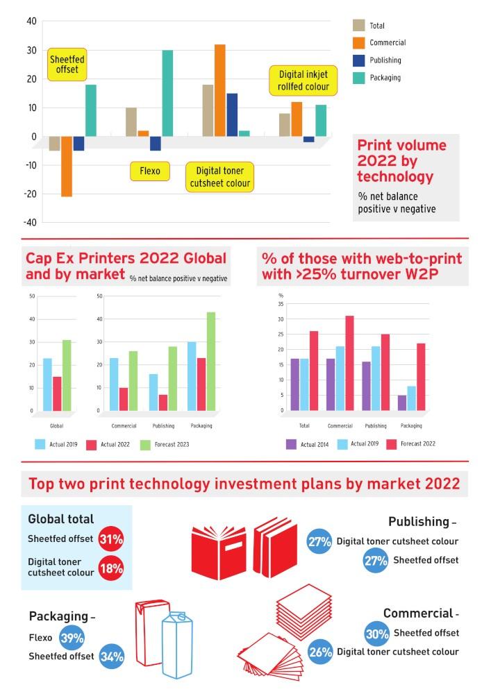
The 8th drupa Global Trends Report will be published in September 2022. The first results from a survey conducted this spring are now available. One important conclusion: overall, confidence is on the rise and all regions and markets forecast higher investment in 2023.
PT XYZ is one of Indonesia’s major flexible packaging manufacturer companies. The company suffers losses from the increase in printing machine breakdown from 1.65% in 2019 to 2.52% in 2021. This paper aims to reduce the breakdown duration in 2022 by identifying and solving the root cause by implementing one of the alternative solutions.

At Oregon based Standard Bag, a 37 year old family run company, the addition of a brand new MIRAFLEX II is opening the door to new possibilities and opportunities.
After nearly 70 years manufacturing capital goods for the flexible packaging converting industry, Comexi is taking a step forward: fully moving into digital technology. At K 2022, the company will present the Digiflex press, its first digital printing solution that enables the flexible packaging industry to meet the current needs of a changing and increasingly demanding market.

2
4 20 46 50 54
68 70

Recycling Of Printed Papers And Usability In Flexo Printed Packaging

The This study aimed to determine whether 100% recycled papers can replace papers made from virgin fibers for the purpose of electrophotographic printing for packaging by evaluating the recycling potential of electrophotographically printed paper using the INGEDE and the washing deinking method. In the first part of the study, typical office copy paper, containing up to 30% recycled fiber, was printed electrophotographically. In the second part of the study, the deinked pulp was then used to prepare the handsheets for deinking evaluation, paper analysis and printability analysis. The print quality of the recycled papers was highly encouraging, as the results were comparable and, in some cases, identical to those of papers manufactured from virgin fibers.
By SINAN SONMEZ, SWATI SOOD, MATTHEW STOOPS, PAUL D. FLEMING III, KECHENG LI, QINGLIU WU and ABDUS SALAM
The traditional method ofproducingpaperfrom pulp derived from raw wood is unprofitable and unsustainable.1 The UN environment program proposes many solutions and goals to help ensure sustainability on earth, including the 12th goal – Sustainable consumption and production. It
aimstodetacheconomic growth from environmental damage, boost resourceefficiency,support the shift to lowcarbon and green economies, and promote sustainable lifestyles. Recycling of paper is oneofthewaystofulfill this goal.2 For more than 30 years, recycled paper has been sold in
the market.3 It is one of the best solutions to lessen environmental issuesandwastegeneration. Recycling decreases the need for new raw materials and prevents the loss of potentially useful resources.4TheDelftUniversity of Technology has conducted a lot of research on the circular
4 www.packagingnewsletter.com

economy regarding packaging.Theuniversity is the founder of the 4R approach, which stands for “recycle, reuse, renew, and rethink.” Recycling in this context refers to using waste packaging materials to create new packaging.5 As the need for packaging board has expanded globally, a significant amount of secondary cellulose raw materials have been produced; these materials make up 25–40% of the municipal solid waste (MSW) that is disposed of in landfills and burned. Because of the production of harmful gases and contaminating leachate, these methods of disposal are not environmentally friendly. Forest resources can be preserved and other environmental effects can be reduced by recycling these fiber sources and using them as raw materials for new sustainable products.6,7 Paper recycling is a major priority for many nations
worldwide. China, for instance, has set up a market-driven paper recycling system. More thanseveralmilliontons of recovered pper are being recycled in the USA and Japan.4 Most countriesalsohavetheir own policies or laws on recycling, for example, Japan has a rigid law called Containers and Packaging Recycling Law to control the wastes in their country.8 In Malaysia, the Solid Waste Management and Public Cleansing Corporation Act (SWCorp) was established by the governmenttosupportandensure the successful implementation of the National Solid Waste Management Policy.9 Therefore, efficient use of waste paper might not only minimize the amount of MSW, but also help preserve and safeguard the environment.7 Additionally, the current approaches to waste management are moving away from waste disposal towards recycling, reusing, and
recovering. According to Bajpai, every ton of recycled paper that replaces a ton of virgin fiber results in a 100% decrease in wood use, a 33% reduction in wastewater, a 27% reduction in energy consumption, a 28%reduction in air particle emissions,anda54%reduction in solid waste. This series of data shows the importance of waste paper recycling.10 As a result, recycling waste paper is becoming more and more popular as a resource saving and environmentally responsible option to producing pulp and paper. However, sometimes recycling of recovered paper has a detrimental impact on the quality of the paper, for instance, recycled paper has a far lower quality than paper generated from virgin pulps because the fibers are shorter and have less tensile strength.10 Paper fibers cannot be recycled continuously since they get damaged in the handling and recycling process. Accord-
6 www.packagingnewsletter.com
ing to some researchers, fibers can be recycled up to seven times.11Everyyear,the paper industry uses 19 million tons of recycled paper to make containerboard, however, with every fiber reprocessing cycle, mechanical characteristics degrade because of the resistance offibertoswellingwhen it is rewet after being dried.12 Papers made from recycled fibers present changes in brightness over time and may turn yellow.11 Some drawbacks in the qualityofrecycledpaper areperceivedbytheuser, such as its opacity (which affects strikethrough or see throughondouble-sided printing), mechanical properties, and printer longevity. The impact of various paper properties that contribute to the printqualityoftherecycled paper is covered in this paper. An improvement in print quality would encourage more people to use recycled paper.3 The majority of paper characteristics al-
so affect how well paper prints electrophotographically. An increase in basis weight, brightness, caliper, density, hardwood fiber content (%), fluorescence, gloss, opacity and porosity would improve print quality, whereas an increase in Parker Print Surf (PPS) roughnesswouldhavetheopposite effect.13 Electrophotography is a dynamic technique that is frequently utilized in copiers, fax machines, and digital printers. It is an imaging technology that uses a photoreceptor, light source, electrostatic principles, and toner to print a digital


file as an output. Despite numerous technological advancements throughout the years, the fundamental technique of electrophotographyhasessentiallyre-

mained unaltered.14
Thecolorgamutofelectrophotographic digital printing is influenced by a number of factors, such as the printer, the toner, and particularly,
7
www.packagingnewsletter.com
the characteristics of the paper (such as its whiteness, roughness, and gloss), which have an impact on the final colorgamutandreplication quality.15 The aim of this study is to perform electrophotographic printing on recycled paper using different deinking methods and analyze the optical, physical, and color variations of the resulting sheets after each recycling stage. Additionally, the properties and printing parameters of the printed papers are


compared. Such studies arecrucialforthepaper, printing, and packaging industry, which is struggling from a lack of raw materials, as well as other financial and environmentalissues.
EXPERIMENTAL Sample
The sample used in this study consisted in recycled papers (electrophotographically printed papers containing up to 30% recycled fiber) with the basis weight of 80 gsm. The
sample papers were printed with an HP LaserJet Printer (P3015) having HP proprietary dry toner. The content ofthesamplewasprinted as 11-point Sans Serif Type, single line spacing, as shown in Figure 1. Each recycled paper was printed on one side, so that the print area represented at least 50% ink coverage, and these prints were then deinked to prepare the recycled handsheets for flexo printing.16

8
www.packagingnewsletter.com
Deinkingconditions
The samples were deinked using two different deinking methods: the INGEDE (International Association of the Deinking Industry) method 11, which is a wellrecognized method to evaluate the recyclabilityofwastepaperinEurope,17 and the washing method. To perform the INGEDE method,
the samples were aged in the oven for 72 hours at a constant temperature of 60 °C, disintegrated, and surfactants were added. The surfactants contained NaOH (0.6%), Na2SiO3 (1.8%), H2O2 (0.7%), and C18H34O2 (0.8%). The recycled pulp slurry that was obtained was diluted to 0.8% Cy and deinked in a Voith flotation cell for 12 minutes. In the washing method

(WM), the sample was aged in the oven in the same way as in the INGEDE method (the sample was kept for 72 hours at a constant temperature of 60 °C). Thereafter, the sample was diluted to 0.8% Cy to form a pulp slurry. This pulp slurry and the displector deinking chemicals, which consisted of a combination water, sodium alkyl sulfate (SAS), specially de-

9
www.packagingnewsletter.com
natured (SD) alcohol, sodium alkyl ethoxylate sulfate, and alkyl dimethyl amine oxide (ADAO), were introduced into the Voith flotation cell (Fig. 2) and the deinking process was performed for 12 min.
Once the deinking process was complete, the pulp was taken out of the flotation cell and was weighed to determine the pulp yield. Sufficient handsheets were then prepared from the deinked pulp (by following the TAPPI Standard T205) and conditioned at 23 ºC, 50% relative humidity for 24 h. The handsheets were then evaluated for deinking efficiency, paper properties (mechanical, optical, and surface properties), and printability (color, optical, brightness, and print performance analysis). The samples were also tested for Parker Print Surf (PPS) porosity (which actually measures air permeability19) by using the PPS tester at 1000 kPa
clamping pressure (CP) with a soft backing. Thickness in micron was determined using a TMI Micrometer. Roughness in micron was assessed using a PPS ME-90 (1000kPa,softbacking) based on TAPPI T555OM-99. Gloss percent was measured at 75º using a Novo Gloss™ Glossmeter based on TAPPI standard T480OM 99. CIE L*a*b* color values were measured using an X rite EXact device in M1 mode, and brightness – with a Technidyne Brightimeter MicroS 5basedonTAPPI Standard T452-OM98 (457 nm light). In the end, all the experimental values obtained for the handsheets were compared with those for the base commercial paper.
Printingconditions
The test samples were printed using a Flexiproof 100 device with cyan commercial ink, providedbyWikoffColor Corporation. For printing, a flexible photopolymer printing plate was
used (size 260 x 90 mm, thickness 1.7 mm and screen frequency 39.37 l/cm (100 lpi)); the digital file shown in Figure 3 was used to print. Prints were carried out at 40 m/min printing speed, 45 units pressure between the anilox roller and the plate cylinder, and 50 units pressure of between the plate cylinder and the impression cylinder. An anilox cylinder withscreenfrequencyof 200.6 l/cm (510 lpi) was used to meter the ink to the plate. The capacity of its ink cells was 5 cm3/m2.20 The values of print density, print contrast, dot gain and CIE L*a*b* values were measured with an X-rite EXact device, usingM1mode, D/50light source under an observation angle of 2° after printing. For calculating delta gloss, the unprinted and printed gloss values were measured at 60º using a BYK micro gloss meter based on TAPPI standard T480 -OM-99.21 Dot roundness was determined
10
www.packagingnewsletter.com
using Paxit software. In the study, the following abbreviations were used: BP – for base paper, WMUPD – for deinked unprinted paper produced using the washing method, WMPUD – for undeinked printed paper produced using the washing method, WMPD – for deinked printed paper produced using the washingmethod,IMUPD for deinked unprinted paper produced using the INGEDE method 11, IMPUD – for undeinked printed paper produced usingtheINGEDEmethod 11, and IMPD – for deinked printed paper produced using the INGEDE method 11. These abbreviations are used in the tables and figures.
RESULTS AND DISCUSSION
Physical and optical propertiesofpaper
Table 1 presents the physical properties of the handsheets obtained by using the
washing method and the INGEDE method. The shortening in the fiber lengths due to the fragmentation after deinking of the long fiber ratio present in the base paper caused an increase in the PPS porosity value. The reason for the increase in the porosity values for the INGEDE method, compared to the washing method, is that the chemicals used in the ink removal process increasedtherateoffragmentation in the fibers.
In addition, the toner particles, which could not be removed from the environment as a result of deinking, closed the existing gaps between the fibers, resulting in a decrease in the porosity values. Itis seen that the surface roughness values of the handsheets deinked by the INGEDE method are slightlylowerthanthose of the handsheets subjected to the washing method. If the handsheets obtained are passed through a calen-
dering process, there will be an increase in the surface smoothness of the handsheets for both deinking methods. The tensile index values of the handsheets (for both the washing method and the INGEDE method) were lower than those of BP, because of the damage produced to the fibers. However, when the burst indices are compared, the values corresponding to the INGEDE method are slightly lower than those of the washing method. In both methods, it is seen that the burst index increases in PD, compared to PUD. This increase indicates a positiveresultoftheremoval of pigment particles from the environment. Regarding the tear index,itisseenthatthere is an increase in the strength values after deinking. The choice of the deinking method did not lead to significant differencesinthetensile index. It has been determined that the rewww.packagingnewsletter.com
11
sistance properties of the papers produced using the washing method are slightly higher than those of the papers producedusingtheINGEDE method (Table 2). The data in Table 3 reveal that the brightness values of UPD handsheets are higher than those of BP for both deinking methods used. This increase is due to the removal of OBA presentin the environment during the deinking process. It wasdeterminedthatthe brightness values of PD and UPD handsheets were affected positively by the INGEDE method, compared to the washing method, and the removal of toner particles from the pulp increased the brightness values for both methods. On the other hand, the increasing amount of toner particles in the pulp alsoincreased the opacity values. It was determined that the washing method increased the brightness of the handsheets, compared to INGEDE, and there was

an increase in the gloss values in direct proportion to the toner particles removed from the pulp. The CIE L*a*b* color values ofthe original copy paper and handsheets are shown in Table 4. By keeping constant the CIE L*a*b* color values of the original copy paper, the paper color difference value (E00) was calculated using Equation(1):(1)whereRT= ahue rotationterm;KL, KCandKH=parametric factors; L*C*h = compensation for neutral colors, SL = compensation for lightness, SC = compensation for chroma, SH = compensation for hue. According to these calculated values, E00 of 1.46 was obtained for WMUPD,
E00 6.88 for WMPUD, E00 1.60 for WMPD, E00 2.52 for IMUPD, E00 5.85 for IMPUD, E00 2.99 for IMPD. These values show that the handsheets deinked using the WM have the closest color tone to the color values of the BP. This obtained color difference indicates that OBA in the recycling pulp was better removed by INGEDE, compared to the washing method. In order to calculate the deinking evaluation factor (DEMLab), the colorvalues in the CIE L*a*b* color system of unprinted paper and printed handsheets are used. For the calculation of the deinkability factor (DEMf) value, the brightness values are
12
www.packagingnewsletter.com
used. The DEMLab and DEMf deinkability factors are given in Equations (2) and (3). The deinking evaluation factor(DEMLab)wascalculated using Equation (2):22,23 ] (2) where US – unprinted deinked pulp, BS – printed undeinked pulp, DS –deinked pulp. The deinkability factor (DEMf) was calculated using Equation (3):17 (3). The deinkability factors are in the range of 0- 100%, values close to 100% indicate excellent ink removal, and values close to 0% indicate poor deinking. The deinkabilityefficiencies of the prepared handsheets are given in Table 5. These values show that higher efficiency was obtained by the washing method than by the INGEDE method. However, it has
been determined that INGEDE is more efficient than the washing method in terms of brightness. VERITY IA Light and Dark Dirt 3.4.0software wasused to determine the dirt count in undeinked and deinked handsheet papers. For use of the software, handsheets were first scanned at 1200 ppi using the Epson Perfection V750 Pro scanner. The minimum speck area settings are defined as 0.02 (T563) and 0.007 mm2. The other dirt analysis settingsare:shape(12.57 300, 12.57 is perfect circle); luminance (0190); and threshold is the background mode minus 30.24 The ink elimination factor (IEERIC) was calculated using Equation (4): (4) where UP – undeinked pulp,DP–deinkedpulp,
UNPR – unprinted pulp. The obtained dirt area and ink elimination factors are given in Table 6. When comparing unprintedpulp,thedirtarea was slightly higher for the WM than for IM. However, the dirt areas of undeinked and deinked pulps using WM were lower than those for IM. When the ink elimination factors were examined, WM showed better results by 1% compared to IM. In the images given in Figure 4, the difference between WM and IM is seenclearly.
Printdensity Density represents the ability of ink to absorb light. Thus, measuring the light reflected from the ink printed surface gives the print density. The resulting value indicates how dark the re-

13
www.packagingnewsletter.com
sulting color appears after printing. A thick ink layer indicates that the ink has a strong ability to absorb light. The higher this value, the higher the density value.25,26.
As may be seen in Figure 5, the BP density value is higher than those for both deinking methods. This is due to the surface roughness andporosityofBPbeing lower than those of produced handsheets. The lower density value of WMPUD is due to the higher surface roughness, compared to those of the other produced handsheets. Since the amount of pigment remaining on the surface will be higher in a substrate with a high surface smoothness and a low air permeability structure, the resulting print density value will be higher. It wasdeterminedthatthe deinkingmethoddid not have a significant impactontheprintdensity value.

14
www.packagingnewsletter.com
Printcontrast
Print contrast is defined asthecapacityofimage detail obtained in the shadow regions of images printed on a printing system. The print contrast with the lowest dot gain at the highest ink density is the ideal value.27 The ratio of the difference between the density of the solid print areaand the printed shadow tint area to the solid density gives the print contrast value and this ratio is expressed as a percentage.28 The values pre-
sented in Figure 3 were obtained by comparing the solid and 75percent dot density values. With the print contrast value, the better ink density of the flexo plate can be controlled. In this, it is important for the flexo plate to receive the right amount of ink from the anilox roll during printing. Figure 6 shows that the toner particles in the undeinked handsheets have reduced the print contrast value. The removal of toner particles from the pulp increased the print contrast. The
print contrast value obtained after deinking is higher than that of the BP. The different deinking methods used made a significant impact on the print contrast.

Tone value increase (TVI)
Tone values are used to obtain colors in multicolored works. Although these values are at a certain level during the design, they exhibit an increase as a result of the printing process. This is called tone value
15
www.packagingnewsletter.com
increase (TVI) in the printing industry.29,30 For this reason, while designing the file to be printed, the necessary tone value selections should be made by keeping the TVI in mind. During this selection, elements, such as paper type, printing type, the ink to be used etc., must be taken into account.31 Dot gain or TVI has two basic components (Fig. 7): the first is the mechanical dot gain, which occurs as a result of the physical spreading of the ink under pressure, and the other is the optical dot gain,whichisformedby the shadow of the light in the substrate around the dot.32 TVI values closetoeachotherwere obtained in the hand-
sheets obtained by both methods, except IMPUD, which showed the lowest TVI values. The smoothness of the surfaceisveryimportantin obtaining dots with sharp lines and without ink loss. If the handsheets are passed through the calendering process, the surface smoothness will increase and quality dots can be obtained (Fig. 8).

Printchroma
The degree of departure ofacolorfrom aneutral color of the same value is called “chroma”.34
The chroma value gives information about the saturation of that color. Low chroma implies weakly saturated color, while high chroma stands for highly saturated color. The units of chroma are dimensionless.35,36

16
www.packagingnewsletter.com
Figure 9 shows that the print chroma values of the handsheets obtained after deinking increased for both deinking methods. It is seen that the print chroma value of the handsheets obtained as a result of deinking by the washing methodishigher.Therefore, higher saturation prints can be obtained. Table 7 illustrates the CIE L*a*b* color values of printed handsheets. The values of E00 Print was calculated by Equation (1). According to these calculated values, E00 of 5.16 was achieved in WMUPD, E002.62–inWMPUD, E00 7.49 – in WMPD, E00 5.74 – in IMUPD, E00 1.68 – IMPUD, and E00 8.66 – in IMPD. These values reveal that the printed handsheets from undeinked pulp have the lowest E00 Print, because both methods include OBA to some extent.Thus,theprintcolor is the closest color tone to the color values of the BP. IM yields bet-
ter E00 Print than WM inthe case ofundeinked printedpapers.
CONCLUSION
The recycling, which was conducted on typical electrophotographic office copy paper, had a positive influence on selected optical, mechanical, and printing properties of the paper. The findings revealed that the roughness was the highest in the WMPUD handsheets, while the thickness, PPS porosity, and permeability were the highest in the IMPUD handsheets. For the samples studied, the tensile index, bursting index, and tearing index remained the highest for the BP. Brightness and opacity were the highest in WMUPD, while gloss remained the highest for the BP. As regards the CIE L*a*b* color values, IMUPD exhibited the highest value of L*, the BP had the highest value of a*, and IMPD –the highest value of b*. Higher DEMLab% was
achievedbythewashing method, while the INGEDE method led to higher DEMf%. When comparing the CIE L*a*b* color values of printed handsheets, the L* value was the highest for IMPUD, BP showed the highest a* value, and WMPUD –the highest b* value, while E00 print was observed to be the highest in WMPD. The differences between 100% recycled papers and papers made of virgin fibres were extremely small, as 100% recycled papers achieved high print quality. Based on the findingsofthisstudyregarding print quality, 100% recycled sheets might completely replace papers made from virgin fibers for use in electrophotographic printing in regular office settings, as well as in flexography in packaging. The variations in flexo printing parametersaretotallyexplainable in terms of residual tonerorink.
17
www.packagingnewsletter.com
1 S. Balda, A. Sharma, N. Gupta, N. Capalash and P. Sharma, Biomass Conv. Bioref., (2022), https:// doi.org/10.1007/s13399 -022-02509-x 2 URL1 (2022), https:// unric.org/en/sdg 12/ (Access date: 05/20/2022) 3 G. Wingkono, T. R. Oswald and J. Stoffel, NIP & Digital Fabrication Conference, 2 (2011), http:// www.hpinvent.com/ hpinfo/newsroom/ press_kits/ 2011/ ColorLokTechnology/ HP_Treatment_Improve _ Quality_Recycled.pdf
4 S. Manandhar, B. Shrestha, F. Sciortino, K. Ariga and L. K. Shrestha, J. Oleo Sci., 71,619(2022),https:// doi.org/10.5650/ jos.ess21396 5 S. Escursell, P. L. Massana and M. B. Roncero, J. Clean. Prod., 280, 124314 (2021), https:// doi.org/10.1016/ j.jclepro.2020.124314 6 O.Laitinen,T.Suopajarvi and H. Liimatainen, Cellulose, 27, 12
(2020), https:// doi.org/10.1007/s10570 -020-03264-w 7 Y. Ma, J.WangandY.Zhang,J. Therm. Anal. Calorim., 129, 1225 (2017), https:// doi.org/10.1007/s10973 -017-6218-3 8 A. Okuwaki, Polym. Degrad. Stabil., 85, 981 (2004), https:// doi.org/10.1016/ j.polymdegradstab.2004 .01.023 9 Y. C. Moh and L. A. Manaf, Resour. Conserv. Recycl., 116, 1 (2017), https:// doi.org/10.1016/ j.resconrec.2016.09.012
doi.org/10.1016/ j.carpta.2021.100135
10 M. Vukoje, I. B. MirkovicandZ.Bolanca, Sustainability, 14, 335 (2021), https:// doi.org/10.3390/ su14010335 11 S. Grilj, T. Muck, A. Hladnik and D. G. Svetec,Nord.Pulp Pap. Res. J., 26, 3 (2011), https:// doi.org/10.3183/npprj2011 26 03 p349 355
12 H. Starkey, A. Chenoweth, C. Johnson, K. S. Salem, H. Jameel et al., Carbohyd. Polym. Technol. Appl., 2, 100135 (2021), https://
13 I. Karlovits, G. Lavric, U. Kavcic and V. Zoric, J. Adhes. Sci. Technol., 35, 23 (2021), https:// doi.org/10.1080/01694 243.2021.1894694 14 Z. Ozomay, C. Sahin and B. Keskin, Journal of Polytechnic, 24, 1213 (2021), https:// dergipark.org.tr/en/ pub/politeknik/ issue/64892/ 884893 15 M. Ataeefard and S. M. S. Tilebon, J. Coat. Technol. Res., 19, 1 (2022), https:// doi.org/10.1007/s11998 -020-00393-6 16 S. Sonmez, Q. Wu, R. Gong, P. D., Fleming and A. Pekarovicova, Nord. Pulp Pap. Res. J., 37, 3 (2022), https:// doi.org/10.1515/npprj 2022 0036 17 U. Yilmaz, A. Tutus and S. Sonmez, J. Adhes. Sci. Technol., 36, 12 (2022), https:// doi.org/10.1080/01694 243.2021.1966256 18 A.Kramer,S.Gaulocher, M. Martins and L. S. Leal Filho, Procedia www.packagingnewsletter.com
18 REFERENCES
Eng., 46, 111 (2012), https:// doi.org/10.1016/ j.proeng.2012.09.453
19 L. Pal, M. K. Joyce andP.D.Fleming,TAPPI J., 5, 9 (2006), https:// imisrise.tappi.org/ TAPPI/Products/06/ SEP/06S EP10.aspx 20 J. I. Podsiadly and H. Podsiadlo, Polym. Res. J., 10, 4 (2016), https:// www.proquest.com/ docview/1898423037? pqorigsite= gscholar&fromopenview=true 21 G. M. Elmas and S. Sonmez, Asian J. Chem., 23, 6 (2011), https:// www.cabdirect.org/ cabdirect/ abstract/20113124 582
22 V. Husovska, J. Pekarovic, A. Pekarovicova and P. D. Fleming III, J. Print Media Technol. Res., 4, 279 (2015), https:// doi.org/10.14622/ JPMTR 1506 23 J. Pan and K. L. Nguyen, Colloid. Surfaces A, 302, 1 (2007), https:// doi.org/10.1016/ j.colsurfa.2007.02.065
24 R. Gong, P. D. Flem-
ing, V. Husovska, J. Pekarovic and J. Cameron, in Procs. TAGA’s 64th Annual Technical Conference, Jacksonville, FL, 2012 25 Y. C. Hou, Pattern Recogn., 36, 7 (2003), https:// doi.org/10.1016/S00313203(02)00258-3 26 E. Bohlin, M. Lestelius and C. Johansson, Nord. Pulp Pap. Res. J., 28, 4 (2013), https:// doi.org/10.3183/npprj 2013 28 04 p573 581 27 S. Sonmez, P. D. Fleming, M. K. Joyce and O. Ozden, “Effects of Coat Weight and Pigment Selection on Flexographic Printability of Coated Test Liners”, TAPPI PaperCon, 2010
28 N. M. M. Mostafa, Int. Design J., 6, 151 (2016), https:// www.faa design.com/ conf/pdf/88f.pdf 29 J. J. Waite and D. Hutcheson, Visual Comm. J., 2007, 29 (2007), https://gceaonline.org/ wpcontent/ uploads/2014/08/2007spri ngvcj.pdf 30 T. Cigula, T. Hudika and D. Donevski, Color Res. Appl., 47, 1 (2022), https://
doi.org/10.1002/ col.22704 31 M. P. Mahajan and S. Bandyopadhyay, Acta Graph., 29, 3 (2018), https:// hrcak.srce.hr/ file/331106 32 M.
Namedanian, D. Nystrom, P. Z. Elias and S. Gooran, in Procs. SPIE 9015 Color Imaging
XIX: Displaying, Processing, Hardcopy and Applications, 9015, (2014), https:// doi.org/10.1117/12.203 5713 33 URL2 (2022), http://the-printguide. blogspot.com/2009/06/ all about dot gaintvitone value.html (accessed on: 05/08/2022) 34 S. Sonmez, Asian J. Chem., 23, 2609 (2011) 35 L. Hellwig and M. D. Fairchild, Color Res. Appl., 47, 1083 (2022), https:// doi.org/10.1002/ col.22792 36 K. A. G.
Smet, M. A. Webster and L. A. Whitehead, Color Res. Appl., 47, 555 (2022), https:// doi.org/10.1002/ col.22749
19
www.packagingnewsletter.com
Optimization of flexo process parameters to reduce the overall manufacturing cost
The flexo process parameters play an important role in ink transfer and will lead to wastage of inks, substrate, solvents and printed stocks if not monitored and controlled. The work focuses on optimizing the flexo process parameters for 40 microns 3-layer polyethylene (PE) film with Blue Nitrocellulose (NC) ink to reduce overall manufacturing cost while maintaining the print quality for diaper application. An experimental design was conducted for the response Ink GSM (grams per square meter), ΔE and Print Mottle with factors such as ink viscosity, anilox volume, plate dot shape and substrate opacity. The data was analyzed through Main Effect, Interaction Plot and Analysis of Variance (ANOVA). The regression models were developed for the response to validate the predictive ability of model. The process optimization resulted in reduction of Ink GSM, ΔE and Print Mottle by 18%, 52% and 1% respectively. The ink consumption reduced by 18.26% with minimized print defects, thereby reducing the overall manufacturing cost.
The As per Mordor Intelligence Report [1], the growth of flexography printing market will be 2.44% CAGR within a period from 2021 to 2026 which accounts to 124.61 USD billion from 107.42 USD billion. A large part of the flexography indus-
try clientele remains to be from the industry catering to the needs of people i.e. personal care products like baby diapers. The India Diaper Market Outlook 2021 [2] reports 22.23% CAGR in baby diaper market over past 5 years. There are al-
most 25 million babies born every year. The hygiene awareness of Indian mothers, rise in incomeofcommonpeople has led to an exponential growth in diaper market. These diapers are packaged in pouches that are printed on Polyethylene (PE) and
20 www.packagingnewsletter.com
Cast Polypropylene
(CPP) films using NC basedinksbyFlexoprocess.Thesurfaceanomalies and print defects, plate fill-ups, frequent machine stoppages, shade inconsistency is one of the major challenges during printing these films. This results in print mottle, uneven print density and ink deposition, thereby depreciating the print quality and degrading the selling potential of the product. Furthermore, the overallmanufacturing cost inclusive of printing, converting and process scrap cost is high. This demands for optimization with tight control of flexo process parameters to minimize the total manufacturing cost with improvedprintquality.
Flexography printing process
Flexography is a printing process which utilizes a flexible relief plate that adheres to a printing cylinder. The usage offlexible (soft)printing plates and low viscosity inks prints on a wide range of absorbent and non-absorbent substrates such as plastics, metallic films, paper and board. These plates are mounted on sleeves that receive ink from the ink pan through an anilox roller. An anilox roller is a cylinder consisting of fixed number of cells with a definite volume. A doctor blade is used to control the amount of ink transferred to the anilox roller. It wipes out any extra ink is collected back to the ink tray. The anilox roller rotates in
the ink tray and carries the ink in its cells to the flexible plate mounted on a sleeve. In this process, ink gets transferred from anilox roller to the raised areas of the plate and thus inking only the image portion. This image area then comes in contact with the substrate and transfers the image onto it by thrusting itself against the impression roller (Figure 1). The pressure between the plate cylinder and the impression roller is termed as kiss pressure and should be just enough to transfer ink from plate to substrate [3].
Flexography process parameters
The parameters that affect ink transfer in flexography and printability

include plate, anilox, ink, substrate, solvents, press speed, surface energy of substrate etc. The printability attributes include density, Tone Value Increase, color deviation (Delta E), gloss, ink coat weight (GSM) and print mottle. Several works have been conducted by researchers to obtain theoptimumprintquality in the flexography print process [4 15]. The cost of print can be easily reduced by increasingtheinkmileage and optimizing the flexo processparameters.
The anilox roller is the heart of flexography process and plays a significant role in ink transfer. The 60 deg hexagonal pattern are shallower and accommodates 15% more cells as compared to 300 hex,450 tri helical and700cellangles.The 600 hex cells provide better dot support duringprinting withgreater uniformity[4].Theflexo ink transfer is directly proportional to the
anilox roller cell volume [5]. A thinner ink film is deposited on the substrate at higher anilox line screen that carries more no. of cells in a given area. This results in less ink transfer due to cell clogging, anilox scoring, and anilox wear. The lower line screen and volume led to a smoother cell surface with consistent ink transfer and print performance. There exists a direct relation between the coating deposit and the volume of the anilox. The ink transfer is governed by type of anilox engraving techniques, inking sys-
tem and plate-making. These parameters allow to accommodate finer screenvolumewithlower cell volume [6-9].
The inkfilm thicknessin flexography process depends upon the anilox volume measured in billion cubic microns. The transfer of ink from anilox to plate is almost 50% and further transfers 50% of the ink from plate to the substrate [3, 10]. In order to avoid print defects such as dirty print and dot dipping, banded anilox test should be performed with varying anilox screen and cell volume to identify the

22 www.packagingnewsletter.com
right specification of anilox roller for optimal ink transfer [11]. The laser engraved ceramic coated anilox roller has better release propertiesascomparedtomechanically engraved chrome anilox roller. The quality of ink laydown improves with ceramic coated anilox rollers [12]. The print consistency shall be achieved by the right selection of anilox screen ruling, volume andcellgeometry[13].
The type of coating and polarity of substrate has a significant effect on print gloss and density. The coating on the substrate provides higher gloss as compared to uncoated substrate. The print density on uncoated substrate is inconsistent due to the ink deposition on the rough areas of the substrate. The presence of coating on the substrate leads to even lay down of an ink. The print density increases with higher polarity of the substrate [14].
The ink film thickness and tone value increase in flexography is affected by the type of substrate, ink and viscosity. The print density increases for both solvent and water based flexo inkswith the increase in anilox volume. The coated substrate reproduces higher print density with solvent-based inksascomparedtowater based inks while the behavior is opposite for uncoated substrate. A higher tone value increaseisnotedwithwater based ink on coated substrate as compared to solvent-based ink which is exactly opposite to uncoated substrate[15].
The solventshave asignificant impact on the accuracy of the structures. The flexographic printing plate material must adapt to the solvents infunctional fluids to avoid plate swelling due to penetration of solvents in plate [16]. The solvents used in flexographic ink play an importantroleinprinted
dot reproduction of both coated and uncoated paper. The dot shape improves with ink having high boiling point solvent and low drying velocity than the ink with low boiling point solvent and high drying velocity[17].
The ink transfer in flexography is governed by the substrate manufacturing processes. The correlation between substrate surface energy and ink surface tension have an impact on ink transfer. The surface treatments increase surface energy of the substrate that reduces the contact angle and improve wettability. The liquids adhere stronger to a surface with high surface energy [18]. The films with higher surface free energy results in higher optical density. A stronger adhesion leads to thicker layer of ink and hence higher optical density. The optical density is greatlyaffectedbypolar component of surface energy in water diluted
23 www.packagingnewsletter.com
inks and dispersive component of free surface energy in solvent based inks [19]. The substrate with lower surface energy reduces wettability and results in higher mottle [20]. The non-uniform corona treatment will result in improper wetting on the printing surface and lead to occurrence of uncovered areas in the print [21]. The dot gain is affected by the nip pressure between plate and impression cylinder. The dot size increases with an increase in line screen [22]. The increased plate to substrate engagement results in reduction in L* values while higher anilox to plate pressure yields higher ink transfer in the mid tone areas. The rise in press speed initially produces a drop in ink transfer but increases with further increased speed, particularly in the highlights [23]. The type of flexo plate making has an impact on print quality. The digital platemaking shows signifi-
cant improvement in print contrast and tonal values as compared to conventional photopolymer plate [24]. The increase in depth of dot, increases dot stability that results in reduced tonevalueincrease.The dot is expanded with an engagement of printing cylinder and impression cylinder. The line rulings on plate affects the image quality if not compensated during pre press[25].
Substrate-inkinteraction
The substrate surface energy, ink surface tension and interfacial tension between substrate and ink dictates the printability in flexography.
Surface energy of substrate
The measure of break up of inter molecular bonds occurring at the surface is referred to as surface energy. In simpleterms,itistheenergy required per unit area to increase the size
of surface and measured in mN/m. In the most basic sense, surface free energy is defined as the adhesive characteristic of the solid, indicating its affinity towardstheothermaterials. The substrate surfaceenergyandinksurface tension are the crucial factors in ink transfer, spreading and adhesion.Thedifference between the surface energy and the surface tension has larger impact on ink transfer and extent of spreading. Higher the difference lowerwillbecontactangle and better is the ink spreading on the substrate. Nevertheless, very high surface energy may lead to erratic print quality. Surface free energy can be calculatedbycontactangle measurement with certain liquids of known surface tension. Contact angle is the angle between a liquid surface and the outline of contact surface of solid. The contact angle of a dropofliquidoverasolid surface is determined
24
www.packagingnewsletter.com
Young
s
described
surface
relation
tension of liquid
interfacial surface tension.
icallygivenby:
contact angle lower will bethewettability.
contact angle of
s = Surface Energy of
L = Surface Tension of Liquid
SL = Interfacial Surface Tension between SolidandLiquid
The contact angle can be measured by either by varying the drop volume or with constant drop volume. The factors that affect contact angle other than substrate surface energy are ink surface tension, its viscosity and wetting speed. The contact angle determines liquid’s wettability on that surface. Thus higher the
Two types of PE substrates were selected for the work having an average opacity of 79% and 82%. The surface energy of these substrates were determined by measuring the contact angle of two test liquids viz., Formamide and Glycerol of known polar and dispersive components. Holmarc Contact Angle Meter was used to measure contact angle on both the substrates with 10 sampleseach.
geometric mean equation was used to calculate the surface energy of these substrates.
25 by
’
Equation. Young
the
between
energyofsolids,surface
and their
Itis mathemat-
=(−)/ (1) Where θ =
liquid γ
Solid γ
γ
The
= +−2 (√+√ (2) γs = Surface Energy of Solid γL = Surface Tension of Liquid γSL = Interfacial Surface Tension between SolidandLiquid The above equation was replaced by simplified Young’s Equation to calculate the surface energy from the contact angle. (1+)= 2 [√+√ (3) Where = = = = of Formamide = 39.5 of Formamide=18.7 of Glycerol = 34 ofGlycerol=30 γLofFormamide=58.2 γLofGlycerol=64 Substrate1 www.packagingnewsletter.com
58.2(1+cos67.51)=2
[√39.5×γsd + √18.7 ×γsp](4)
64(1+cos80.78)=2
[√34×γsd + √30 ×γsp] (5)
Solving equation (4) and (5), polar and dispersive components of substrate 1 was calculated
γsd=42.05 and γsp=0.0225
Therefore, Total Surface Energy of PE laminate forSubstrate1 = γsd+ γsp=42.26 mN/ m
Substrate2
58.2(1+68.6)=2
[√39.5× + √18.7 ×]
64(1+81.48)=2
[√34× + √30 ×](7)
The polar and dispersive component of Substrate 2 was hence calculated by solving equation (6) and(7).
γsd=40.70 and γsp=0.00722
Therefore, total Surface Energy of PE laminate forSubstrate2
= γsd+ γsp=40.7mN/m Substrate 1 and Substrate 2 are different in only opacity. The opacity of substrate was varied to check it’s effect on print attributes. Both the substrates are 40 μ thickness(37GSM)with 0.943 density. The gloss of the substrates was 65% @ 600. The Coefficient of Friction (CoF) was ranging between 0.3 to 0.4 while Haze between10%to15%.
The contact angle was found to be lower at 20 sec viscosity (Table 1), thereby resulting in higher ink spread and printmottle(Figure2). Surface Tension is defined as the amount of energy required to increase the surface of the liquid by unit area. The surface tension was determined based on Wilhelmy Plate method
= Force acting on the plate
=Surface tension of liquid(ink)
= Wetted perimeter of theplate
= Contact angle with plate
Where,
Surface tension measurement was conducted on 10 samples of ink to increase accuracy of measurement. The mean surface tension was found to be 23.98mN/m at 220C. The temperature is a crucial factor affecting surfacetension.Therise in temperature exerts more molecular vibrations among the liquid molecules, thereby decreasing surface tension. The increase in temperature, increases adhesion and decreases the cohesive forces between liquid molecules. This results in increased contact angle and reduced surface tension. The ink-substrate interaction is critical to print quality. The ink lay down over the substrate after transfer from the
26
[26]. = (8)
www.packagingnewsletter.com
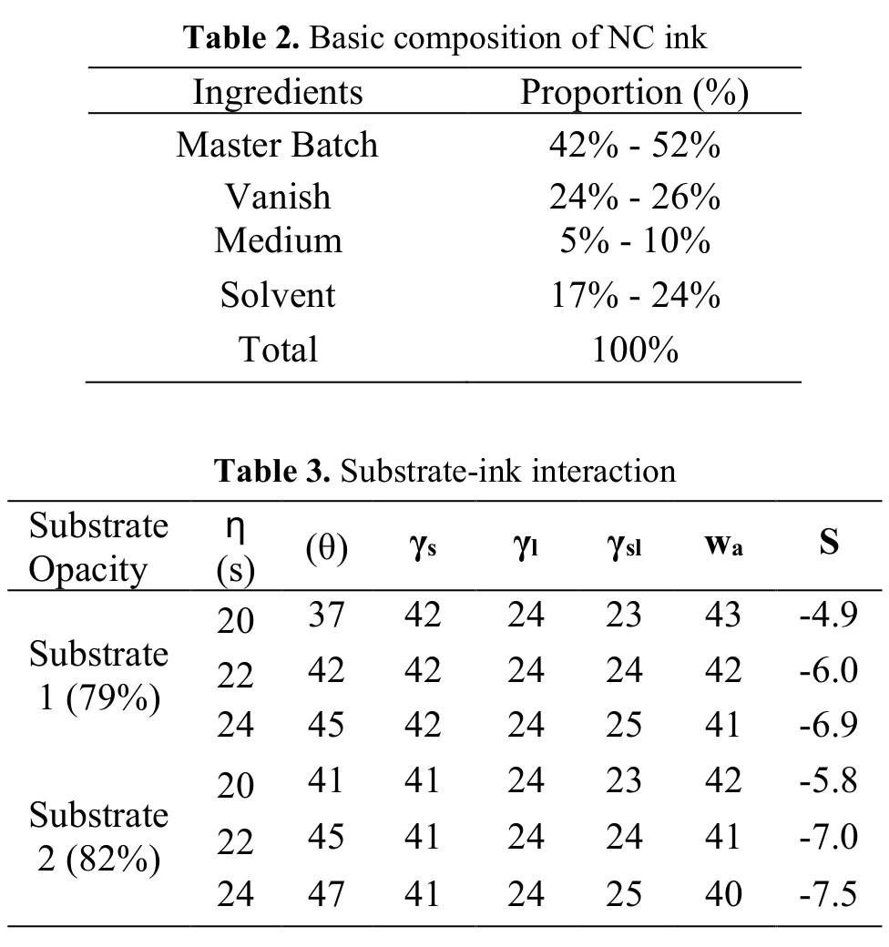
plate has an impact on printability. The ink spreading depends on various printability factors such as circularity, area and perimeter of the dot. Moreover, it reflects directly on print defects such as voids and print mottle. A higher spreading tendency of ink over the substrateleadstobetter area coverage, reducing void area. On the contrary, spreading yields in scattered distribution of pigment particles with uneven reflectance from the printed substrate, thus leading to higher print mottle over non-absorbent substrates. NC based ink was prepared in a dispenser that comprised of Master Batch, Varnish/Resin, Medium and Solvent. Master Batch is a combination of Pigment, Additives, Varnish and True Solvent (Table 2).
The interfacial tension (γsl), work of adhesion (Wa) and spreading coefficient (S) was calculatedusing
followingformulae:
γsl= γs γl(Cosθ)(9)
S= γs -γl -γsl(10)
where θ = Contact angle of ink with substrate.
The values of contact angle from Table 3 suggest higher spreading at lower ink viscosity (20 sec) for both the substrates. The higher surface energy of substrate 1increasestheabilityof the substrate to bind with ink. Higher surface energy ensures higher spreading as the amount of spreading is

directly proportional to the difference in substrate surface energy of substrate and ink surface tension. This difference is found to be greater in substrate 1 and hence the ink spread is more in substrate 1 than substrate
2. Furthermore, the lower contact angle at lower viscosity resulted in higherink spread and print mottle. A higher adhesion between the ink and substrate is achieved on substrate 1 as indicated by higher work of adhesion (wa). The negative values of
27
www.packagingnewsletter.com
spreading co-efficient (S) suggest that the spreading does not occur spontaneously. Substrate 2 displayed lower ink spread indicated by higher magnitude of S. Thus,20secinkviscosity on substrate 1resultedinhigherinkspread.
Printabilityanalysis
Printability is essential for defining the optimum settings for improving print quality in flexography printing press. Printability in this study is defined as the optimal amalgamation of ink, substrate and process parameters for the responses such as ink gsm (grams per square meter), ΔE*00 and print mottle. The optimizationoftheseresponses with minimized defects shall enhance printability and reduce the overall manufacturingcostofapackage.
Platedotstructure
Two plates, with dot structure 1 (circular) and dot structure 2 (square) were used for
thestudy.Theplatelayout design comprised of logo, solid and halftone patch, surface and reverse text. The solid patch was included to measure and analyze Ink GSM, ΔE*00 and Print Mottle. The halftone patch was used to check the tone value increase. The logo was incorporated in the layout for visual assessment while surface and reversetexttocheckminimum reproducible text.
These plates were mounted on the same sleeve and printing was carried out by keeping the other color parametersconstant.
The dot circularity also referred to as roundnessandrepresentedas =42(11)
where A = area of dot and P = perimeter or thedot
The ideal dot circularity is 1 and more closer to
28
www.packagingnewsletter.com
1, better is the dot reproduction. The dot circularity of Dot Shape 1 (0.8194) was found to be higher than Dot Shape 2 (0.8163) as indicatedbyFigure3.
Baseline identification
A production run was conducted on 40μ PE substrate with solvent based blue ink at 23s ink viscosity (300C and 50% humidity) as measured by B4 Ford cup and diluted with n propanol and n propyl acetate in the ratio of 4:1. A anilox cell volume of 5.3 billion cubic microns (BCM), square dotplateand79%average substrate opacity was used for the run. The other constant parameters set during the press run were 5.83 m/ s press speed, 1.7 mm plate thickness, medium backing tape with 0.38 mm thickness and 300 reverse angle chambered doctor blade. The assessment of response Ink GSM, Color Devia-
tion (ΔE*00) and Print Mottle was done with 20 printed sheets being considered as sample size for each response. The baseline for Ink GSM and Print Mottle was the mean value of the sample size. The baseline or reference L*a*b* values for the blue color was 14.42L* 36.22a* -66.53b* and thetargetwassettoreduce the color deviation from the baseline for the printed blue sample
with ΔE*00 not exceeding1.5(Table4).
The selection of anilox roller cell volume was based on ratio of plate to anilox screen ruling and the available inventory used in daily production run. The plate to anilox screen ruling was kept in a range of 1:5 (5.3 BCM) and 1:7 (4.5 BCM) with plate screen ruling as 133 lpi while anilox screen rul-
29
www.packagingnewsletter.com
ing as 648 lpi and 914 lpi.
A general full factorial experimental design was run with 4 factors namely viscosity with 3 levels while anilox volume, dot shape and substrate opacity at 2levels and 2 replicates, thus totaling to 48 runs (Table5).Thedotshape 1 refers to dot circularity of 0.8194 while dot shape 2 refers to dot circularity of 0.8163. The lower level of substrate opacity represents mean opacity of 79% while higher level represents mean opacityof82%.Theselection of levels for the factors in DOE were considered based on the working levels. A viscosity lower than20secwillresultin more tone value increase and mottling while viscosity above 24 sec will clog the anilox cellsandyieldinuneven lay down of an ink. Anilox volume levels were considered based on ratio of plate to aniloxlinescreen.There
are only two types of dot shape available round and square, hence considered. The recommended substrate opacity for the diaper application is normally ranging between 80% to 82%. The substrate opacity below 79% will result in dispersion lines on PE substrate while opacity above 82% will require more addition of master batch, thereby increasing the production cost. Hence, the two opacity levels of 79% and 82% were consideredforthework.
Ink GSM
Ink GSM is the amount of ink deposited over

one square meter of printed substrate. The Ink GSM was measured on solid patch of the printedsample.
The main effect plot (Figure 4) shows that higher ink GSM is obtained at higher viscosity (24 sec) and anilox volume (5.3 BCM) with acirculardot(dotshape 1) on lower substrate opacity. The solid content in the ink is higher at 24 sec viscosity that constitutes higher ink GSM. The anilox volume determines the quantity of ink transfer to the plate and further on to the substrate. Higher the aniloxvolume, highertheamountofinkde-

30
www.packagingnewsletter.com
posited and therefore the ink GSM. The larger area coverage on plate with dot shape 1 (circular dot) led to higher ink transfer and ink GSM. The difference between substrate surfaceenergyandinksurface tension played a significant role in ink transfer.Thesubstrate1 with higher surface energy showed higher difference thatled to more ink transfer. A higher surface energy increases the force of adhesion betweentheinkand the substrate. This force of adhesion pulls more ink from the plate and hence results in a higherinkGSM.
Thereis nostrong interaction between the factors affecting ink GSM (Figure 5). High ink GSM is obtained when an ink having 24 sec viscosity is used irrespective of the plates, anilox volume and substrate used. Similarly anilox volume of 5.3 BCM, dot shape-1 and substrate opacity-1


yielded maximum ink GSM. Minitab 17 was usedtocalculateANOVA (Analysis of Variance) and Regression models for Ink GSM, ΔE and PrintMottle.
The degrees of freedom abbreviated as df (Table 6) are the number of values that can be varied once certain parameters have been established.
31
www.packagingnewsletter.com
Adjusted Sum of Squares (Adj SS) are measures of variation for different components of the model. Sum of Squares describe the variation due to different sources. Adjusted Mean Square (Adj MS) measures the description of magnitude of variation by the term or model. Adj MS takes into consideration df. The F value is the test statistic used todetermine whether the term is associated with the response. It is the ratiooftwosamplevariances i.e. MS of a particular row divided by MS Error. The p-value is the probability that measures the evidence against the null hypothesis. The lower p-values provide the stronger evidence against null hypothesis. The constants of the regression equation was derived from the coefficients of each term namely Viscosity, Anilox Volume, Dot Shape, Substrate Opacity and interactions betweenthem.
The p-values in ANOVA (Table 6) of all the main factors are below α valueof0.05,therebyindicating as significant factors affecting Ink GSM. The lower p-values below α value of 0.05 proves rejection of null hypothesis. The viscosity was found to be of highest significance af-
fecting Ink GSM as indicated by higher F-value. A 99.74% of variability could be explained by the model as indicated by R-Sq. value. The adjusted R-Sq of 99.70% shows significant improvement of the model with selected four factors. As the experimental design involved

32
www.packagingnewsletter.com
2 replicates i.e. having multiple observations with an identical X values, hence lack of fit testwasperformed.The p-value greater than α>0.05 indicates that model correctly specifies the relationship between the response and predictors and the test does not detect lack of fit. The model was adequate as the lack of fit (p=0.568) value was greaterthan α>0.05.
Printdensity
The print density is directly correlated to ink GSM and therefore the trend for Ink GSM and print density is same as indicated by Main Effect Plot.
The main effects plot (Figure 6) shows that higher print density is obtained at higher viscosity, higher aniloxvolume, a circular dot shape and on a surface with lower opacity. A lower viscosity (20 sec) implies a lower concentration of solid content and hence a lower print

density was achieved. A lower anilox volume (4.5 BCM) resulted in a lower print density. This occurred due to the fact that a lower anilox volume will store a less amount of ink and
therefore will transfer lesser ink and hence a low print density. The dot shape 1 i.e. circular dots exhibited higher print density than square dotted plate. Thiscanbeattributedto
33
www.packagingnewsletter.com
thefactthatareacoverage of circular dot is more than square dot (dot shape 2) and transfers more ink as compared to a square dot. The substrate 1 withlower meanopacity of 79% displayed a higher print density than substrate 2 i.e. mean opacity of 82.4%. A higher ink transfer was observed at lower substrate opacity 1 due tohighersurfaceenergy of 42.26mN/m as compared to higher substrate opacity with a lower surface energy of 40.7mN/m that has led tohigherprintdensity.
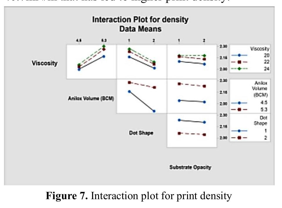
The interaction plot for density (Figure 7) shows higher density at 24s viscosity, 5.3 BCM anilox volume for a circular dot shape at lower substrate opacity. The interaction of viscosity with anilox volume, dot shape and substrate opacity affects the print density. The higher solid content at 24 sec ink viscosity and more ink carrying capacity of 5.3 BCM anilox volume re-
sulted in high ink deposition on to the substrate; thereby higher printdensity.Thehigher area coverage of plate dot 1 and higher viscosity of 24 sec with less ink spread yielded in higher ink film thickness, thus higher print density. The ink with higher viscosity, high anilox BCM and circular dots yield high print densities. The interactionplotshowsgreatinter dependence ofcircular dots with anilox volume. A sharp rise in print density was observedwithcirculardots at 4.5 BCM anilox volume as compared to square dots. The higher ink transfer at lower substrate opacity with higher surface energy was achieved at 24 sec inkviscosity.
DeltaE
color variation or deviation in the print is referredtoasDeltaE.It involvesa3dimensional color space
refers to lightness and darkness of a color. The a* refers to green and red coordinates
yellow and
val-
34
The
where each color occupies unique location according to its color co-ordinates namely L*, a* and b*. The L*
while
blue coordinates are represented by b*
ues. Δ2000=√(Δ′ )2+(Δ′ )2+(Δ′ )2+(Δ′ )(Δ′) (13) Where,L′= (L1+L2)/2 C1 = √12+12, C2= √22+22 C = (C1 + C2)/2 G = 12 (1−√−7−7+ 257) 1′ = a1(1 + G), 2′ = a2(1 + G) C1' = √1′+12 , C2' = √2′+22 C′ = (1′+ 2′)/2 ΔL′ = L2 − L1, ΔC′ = C2' − C1' ΔH′= √C1'C2'2sin(Δh′/2) SL = 1 + 0.015(L′−50) 2√20+(L′−50)2 SC=1+0.045C′, SH=1+0.015C′T Δθ = 30exp{−(H′−275°25)2} RC = √C′7C′7+252, RT= RC sin(2Δθ) KL = 1 default, KC = 1 default,KH=1default www.packagingnewsletter.com
The color values of 14.42L* 36.22a*66.53b* was considered as reference based on the customer approval. The color deviation was calculated based on CIE ΔE2000 (weighing factor 1:1:1) with M1 measurement mode, D50 illuminant and 20 observer angle between reference L*a*b* and L*a*b* values of printed samples measured on the solid patches. The Main Effect plot (Figure9),depictslower delta E at higher viscosity and anilox volume withsquaredotonhigher substrate opacity. The plot (Figure 10) indicates an interaction of viscositywithaniloxvolume and dot shape and anilox volume with dot shapeaffecting ΔE*00.

Equation for ΔE*00
E2000 = 9.57 -
-
The constants of the regression equation were derived from the coefficients of each factor and their interactions with each other. The
Table (Table 7) shows that all the main effects and interaction of viscosity with anilox volume, dot shape and
anilox volume with dot shape as significant factors affecting Delta E. Dotshapewashadainfluential role inminimizing Delta E. The model summary indicates 97.20% of variability explained by the model while 96.8% adjusted R -Sq implies significant improvement of the modelbyusingfourfactors. The lack of fit with
35
Regression
Δ
1.792Viscosity(sec)
0.53AniloxVolume(BCM) +22.753DotShape + 0.3477Viscosity*AniloxV olume 5.005AniloxVolume (BCM) + 22.753DotShape(14)
ANOVA
www.packagingnewsletter.com
p value of 0.051 represents the accuracy of themodel.


Printmottle
Print Mottle is defined as the undulations present on the surface of substrate. Verity IA Print Target v3 software with Stochastic Frequency Distribution Analysis (SFDA) algorithm was used to measure Mottle on the solid patch. The output result of this algorithm is an index, quantifying mottle. SFDA firstly determines the properties ofthe texture oftheimage and then calculates the spatial distribution of the texture. When the scanned image area in digital format is fed to SFDA for analysis, the entire image area is sampled into a regular pattern of continuous andadjoininglarger target areas which are further sub-divided into smaller pixel targets (Figure 11). The larger targets are measured for two parameters stored in separate data-
bases simultaneously; one database stores the two-dimensional standard deviation (s) within the smaller target area while the second database stores the mean
luminance value (MTL) of the pixels present in the smaller target area that describes the overall visual impact of the analyzed larger target area. When an area of
36
www.packagingnewsletter.com
index
spective area of interest
standard deviation
pixel
pixels
target
Number of pixels in thetarget.
The level of uniformity among the targets is indicatedbythedegreeof variation in the value of

s” while the uniformity in luminance is indicated by the variance of
MTL”.
mottle of the larger target is then calculated using the following formula.
Mottle =
Meanof
s
for more accurate mottle measurement. For calculating the mottle index of the entire area of interest, spatial distribution of texture mottle is calculated between the larger targets, by the following formula:
values
The variation in the texture
image also
SpatialMottle = K* (
o* Mo)(17)
37 interestisselectedwithin the scanned image, the s and MTL values are extracted from their databases and the mottle
for the re-
isdisplayedasaresult. The
“s” iscalculatedas: =√Σ(−)2 (15) Where, PL Individual
luminance MTL Meanluminance of the
in the
area n
“
“
The
K* (σs* Ms* σm)(16) Where, K -ScalingFactor, σs Standard deviation ofsvalues σm Standard deviation ofMTLvalues Ms
“
”
of
needs to be calculated
σ
www.packagingnewsletter.com
deviation of large target mottlenumber

MO=Meanoflarge targetmottlenumber
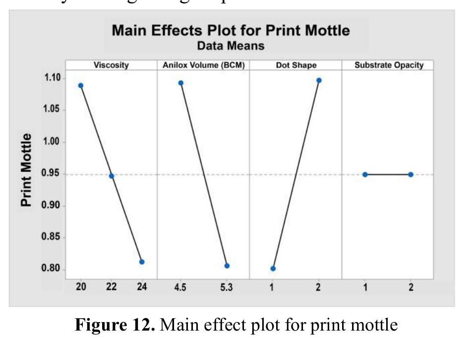
The Print Mottle was measuredonsolidpatch of the printed sample. The solid print mottle wasminimized athigher level of viscosity (24 sec), anilox volume (5.3 BCM), substrate opacity and lower level of dot shape (Figure 12). The higher ink spreading at lower viscosity (20 sec) due to higher spreading coefficient of ink results in uneven inkdeposition on the substrate, thereby leading to higher printmottle.
The even lay down of ink on the substrate at higherviscosity(24sec) reproducesgooddotcircularity, thereby resulting in lower print mottle. Too higher viscosity willresultinhigherprint mottle due anilox cell clogging. The outcome of this result will be uneven deposition of ink on the substrate. The
print mottle was reduced at higher anilox volume and circular dot (dot shape 1) due to higher and uniform ink film deposition. Though the print mottle was minimized with higher
opacity substrate but the difference between both the substrate was negligible. This is because of lower surface energy of substrate 2 that led to less ink
38 σO = Standard
www.packagingnewsletter.com
spread as compared to substrate1.

The interaction plot (Figure 13) shows lower solid mottle at 24 sec viscosity, 5.3 BCM anilox volume with a circular dot on 82% mean substrate opacity. The interaction of lower anilox volume and lower viscosity yields a high mottleindex.Thehigher solvent content at lower viscosity (20 sec) with lower anilox volume (4.5 BCM) results in uneven ink deposition on to the substrate, thereby higher print mottle. The lower dot circularity at lower viscosity with squaredotleadstouneven distribution of ink on the substrate, thereby resulting in higher solid mottle. There was nosignificantinteraction of substrate opacity with other factors and hence was not responsible for any change in solidmottle.

39
Regression Equation for PrintMottle www.packagingnewsletter.com
The regression constants were derived from the coefficients of factors Viscosity, Anilox Volume, Dot Shape and the interactions of Dot Shape with Viscosity and Anilox Volume. Table 8 indicates that viscosity, anilox volume and dot shape along with their interactions have significant effect on minimizing print mottle. The lack of fit with p value of 0.247 represents model adequacy.
The regression equations for Ink GSM, Delta E and Print Mottle were validated by conducting additional runs. The data between Actual and Predicted runs showed R2 value of 0.9242, 0.9372 and 0.9226 for
Ink GSM, Delta E and Print Mottle respectively; hence justifying the predictive ability of the models.
Response optimization
The paramount settings for all the print attributes were optimized from the trials conducted as per the experimental design through response optimizer to identify the set of variables for multiple re-
sponses. The optimal settings for a single response areevaluated by individual desirability while composite desirability for multiple responses in the range of zerotoone.Theindividual desirability will be 1 if the predicted response is closer to the target. The combination of individual desirability is calculated into an overall value as composite desirability for multiple responses. The
40 www.packagingnewsletter.com Print Mottle = 0.3250 + 0.00875Viscosity(sec) 0.0073AniloxVolume (BCM) + 2.5384DotShape - 0.05188Viscosity* DotShape 0.23438AniloxVolume* DotShape(18)
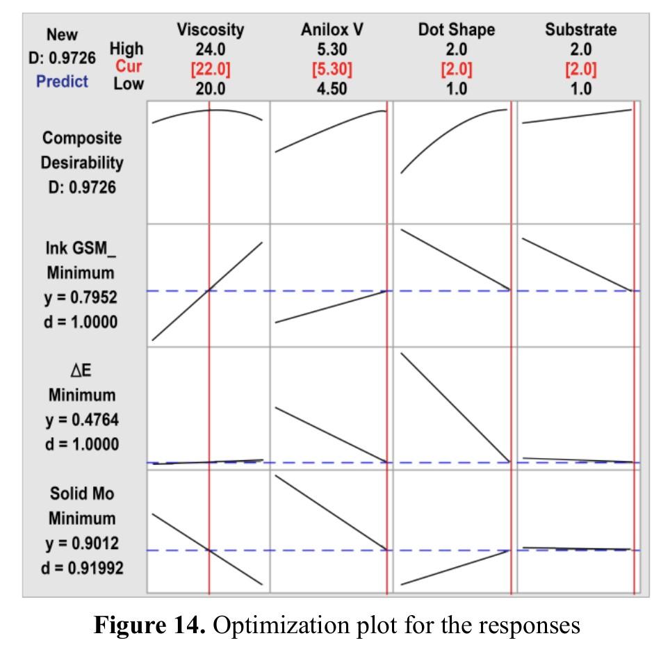
higher the composite desirability value, the bettertheproductquality. The response optimizer provides the "best" combination of variable settings as the global solution.The goal was set to minimize the response such as print mottle, ink GSM, and delta E. The composite desirability was estimated at different levels of anilox cell volume (BCM), viscosity, dot shape, and substrate opacity to identify the sweet spot between parameters fulfilling the goal.
The desirability to minimize a response is calculatedasbelow.
di=0(i>Ui)(19)
di = ((Ui - i)/(Ui - Ti)) ri(yTi< i<Ui)(20)
di=1(i<Ti)(21)
Where, i = predicted value of ithresponse
Ti = target value for ith response
Ui = highest acceptable valueforithresponse
di = desirability for ith response
Individual Desirability = (Upper value – Predicted response)/(Upper value–Target)
CompositeDesirability,
D = (d1 * d2 * …* dn) 1/n(22) Where n = number of responses
D = Composite Desirability
The optimization plot (Figure 14) revealed global solution as 22 viscosity, 5.3 BCM anilox volume, dot shape2(square)having 82% substrate opacity (2) with 0.9726 composite desirability for minimization of Ink GSM, Delta E and Print Mottle on40μ PEfilm.

The optimized settings with 22 sec viscosity, 5.3 BCM anilox cell volume, dot shape 2 (square dot) and 82% substrate opacity was run and average data of

41 www.packagingnewsletter.com
20 printed sheets was considered.
The area of one repeat of the job was 0.23 m2 and accommodates 113 repeats/prints in a Kg. An Ink GSM of 0.98 was achieved during the production run while 0.80 for optimized run. The ink consumption per 0.23 m2 for production run was 0.23 gm while 0.19 gm for optimized run. Table 10 shows minimization in ink consumption by 18.26% at optimized run of 22s viscosity and 5.3 BCM anilox volume with square dot plate (dotshape2)on40μ PE film a substrate having mean opacity 82% (substrateopacity2).
Conclusion
A general full factorial DOE was designed to optimize flexo process parameters. The process parameters considered for experimentation were anilox volume (BCM) and dot shape at two levels while ink viscosity at three levels for both the substrates
having mean opacity of 79% and 82%. The analysis of the data was assessed by main effects, interaction plot and ANOVA to determine the best combination of flexo process parameters enhancing printability. Furthermore, regression models were generated for the output response Ink GSM, Delta E, Print Mottle and validated. The validation runs for Ink GSM, Delta E and Print Mottle revealed good predictive ability of the models with R2 value of 0.9242, 0.9372 and0.9226respectively. The results revealed that ink viscosity, anilox volume, dot shape and substrate opacity were significant factors affecting the response. The other factors such as a press speed, plate type, plate thickness, backing tape, doctor blade angle will also have a significant impact on ink transfer, therebyaffectingtheresponses. The Response Optimizer revealed the optimized settings as 22
sec viscosity, 5.3 BCM anilox cell volume, dot shape 2 (square dot) and 82% mean substrate opacity on 40μ polyethylene film. However, the same methodology can be applied for other inks to validate the results for optimization and ink consumption. The optimal settings minimized the ink consumption by18.26% while maintaining the desired ΔE*00 and reductionin overall manufacturingcostofapackage.
Acknowledgments
The author would like to thank Parakh Flexipacks and Windmöller & Hölscher India Private Limited for their infrastructure and financial support.
References
[1] Mordor Intelligence Report (2020). Flexible PlasticPackagingMarket by Type (Pouches, Rollstocks, Bags, Wraps), Material (Plastic & Aluminum Foil), Application (Food, Beverage, Phar-
42 www.packagingnewsletter.com
ma & Healthcare, Personal care & Cosmetics), Technology, and Region Global Forecast to2025[online].Available from: https:// www.marketsandmarket s.com/Market Reports/ flexible-packagingmarket-1271.html. [Accessed 20 May 2021].
[2] Indian Diaper Market (2016). IndiaDiaper Market Overview, 2016 - Research and Markets [online]. Available from: http:// www.businesswire.com/ news/ home/20161128005918 /en/India-Diaper-Market Overview 2016 Research. [Accessed 20 May2021].
[3] Kipphan, H. (2001). Handbook of Print Media. Springer-Verlag, Heidelberg,Berlin.
[4] Rogers A. (2011). Choosing the right anilox roll engraving for the application [online]. Available from: http:// www.harperimage.com/ media/downloads/ Choosing%20the%
20right% 20engraving_Converting%20Q% 204thQrtr2011.pdf. [Accessed 20 May 2021].
[5] Ardent D. (2006). Ink Mileage: Measure & Manage [online]. Available from: http:// www.pffc online.com/ processmanagement/5017paper ink mileage measure. [Accessed 20 May2021].
[6] Rastetter J., & Bingham J. (2016). Lower Your Anilox Line Screen andCellVolumeforBetter Performance FlexoGlobal [online]. Available from: http:// www.flexoglobal.com/ blog/2016/08/01/ pamarco lower anilox line-screen-cellvolume/. [Accessed 20 May2021].
[7] Teufler S. (2010). Weighing Your Coating Options [online]. Available from: http:// www.harperimage.com/ media/downloads/ Weighing%20Your% 20Coating%20Options%
20FLEXO%20Feb%
202010.pdf. [Accessed 22May2021].
[8] Teufler S. (2015).
Anilox Rollers - Choosing the Right Lineature [online]. Available from: http:// www.harperimage.com/ media/downloads/ Anilox%
20Rollers_Choosing% 20The%20Right%
20Lineature_Flexible%
20Packaging%
20Issue%201.pdf. [Accessed 22 May 2021].
[9] Hogan P. (2018). Aniloxes - Yesterday,Today and Tomorrow [online]. Available from: http:// www.harperimage.com/ media/downloads/ Aniloxes_Yesterday% 20Today%20and% 20Tomorrow_% 20L&NW%20NovDec% 202018.pdf. [Accessed 22May2021].
[10] Harper C. (2005). Do you know what ink film thickness is transferred [online]. Available from: http:// www.harperimage.com/
www.packagingnewsletter.com
43
media/downloads/ Harper_FGA_1_2005.pdf. [Accessed 22 May 2021].
[11] Green C. (2013). Understanding Common Flexo Print DefectsPart 2 FlexoGlobal [online]. Available from: http:// www.flexoglobal.com/ blog/tag/anilox/ page/4/. [Accessed 22 May2021].
[12] Poulson B. & Hudson K. (2010). Correlating Ink Labs Drawdown to Press [online]. Available from: www.harperimage.com/ media/downloads/ Radtech%20Report% 20Sep-Oct% 202010.pdf. [Accessed 24May2021].
[13] Harnandez R. (2019). Releasing the Anilox’s Power [online]. Available from: http:// www.harperimage.com/ media/downloads/ Releasing%20Anilox% 20Power_FLEXO% 20Jan%202019.pdf.
[Accessed 24 May 2021].
[14] Olson, R., Yang, L. Stam J. V., & Lesrelius, M. (2006). Effects ofink setting flexographic printing: Coating polarity and dot gain. Nordic Pulp and Paper Research Journal, 21(5), 569 574.
[15] Gencoglu, E. N. (2012). Influence of Ink Viscosity on Dot Gain and Print Density in Flexography.AsianJournal of Chemistry, 24(5), 1999 2002.
[16] Theopold, A., Neumann, J., Massfelder, D., & Dörsam, E. (2012). Effects of Solvents on Flexographic Plates. Advances in Printing and Media Technology, 39, 159–168.
[18] Hizir, F.E., & Hardt, D.E. (2014). Effect of Substrate Contact Angle onInkTransferinFlexographic Printing [online]. Available from: http:// www.comsol.co.in/ paper/ download/194575/ hizir_paper.pdf.
[Accessed 26 May 2021].
[19] Izdebska, J., Podsiadlo, H., & Hari, L. (2012). Influence of Surface Free Energy of Biodegradable Films on Optical Density of Ink Coated Fields of Prints. Advances in Printing and Media Technology, 39,245 252.
[17]
Simseker, O. (2011). Investigation of Different Solvents in Flexographic Printing Ink’s Effects to Print Quality on Coated and Uncoated Paper. Asian Journal ofChemistry, 23 (7),2903 2906.
[20]Rong,X.,&Keif,M. (2007). A Study of PLA Printability with Flexography. The Technical Association of the Graphic Arts,3, 605 613.
[21] Mesic, B., Lestelius, M., & Engstrom, G. (2006). Influence of Corona Treatment Decay onPrintQualityinWater borne Flexographic Printing of Low density
www.packagingnewsletter.com
44
Polyethylene-coated Paperboard. Packaging TechnologyandScience, 19(2),61 70.
[22] Valdec, D., Zjakić, I., & Milković, M. (2013).TheInfluenceof Variable Parameters of Flexographic Printing on Dot Geometry of Pre printed Printing Substrate. Tehnički vjesnik, 20(4),659–667.
[23]Claypole,T.C.,Jewell, E.H., & Bould, D.C. (2012). Effects of Flexographic Press Parameters on the Reproduction of Colour Images. Advances in Printing and Media Technology, 39,187 194.
[24] Gilbert, D.E., & Lee, F. (2008). Flexographic Plate Technology: Conventional Solvent Plates Versus Digital Solvent Plates. Journal of Industrial Technology,24(3), 1–7.
[25] Bould, D.C., Claypole, T.C., & Bohan, M.F.J. (2004). An Investigation into Plate Deformation in Flexographic Printing. Journal
of Engineering Manufacture, 218(11), 1499–1511.
[26] Ebnesajjad, S., & Landrock, A. (2015). Surface Tension and Its Measurement. In: S. Ebnesajjad, 3rd ed. Adhesives Technology Handbook. William Andrew, Elsevier Inc, 19 29.
Akshay V. Joshi received Bachelor’s and Masters Degree in Printing Engineering from University of Pune, India. He was awarded Ph.D. (Engineering) from Jadavpur University, Kolkata in 2015. Dr. Akshay Joshi is working as Assistant Professor, PrintingEngineeringDepartment at P. V. G’s CollegeofEngineering& Technology and G. K. Pate (Wani) Institute of Management, Pune, India since 1996. He is Coordinator, Board of Studies and Member, Research and Recognition Committee for Printing Technology at Savitribai Phule Pune University. His area of
research is Gravure, Flexo and Flexible Packaging. Dr. Akshay Joshi has published several papers in Journals and guided candidates for MasterPrograminPrinting Engineering and evaluated Ph.D. candidates. He is been internationally qualified as G7ExpertbyIdealliance USA and implemented first G7 calibration for Gravure and Flexographyprintingprocesses in India. He is a Life MemberofIndianSociety for Technical Education. http:// orcid.org/0000 0002 8733-1747
45 www.packagingnewsletter.com
The Future of Package Printing to 2027
This report covers the print for packaging market over the period 2017–2027. It explores the restraining factors in play, including the increasing demand for more sustainable packaging; this will alter patterns of demand between packaging materials, as well as restraining overall demand in the market to some extent.
In 2022, the package printing market was estimated to be worth $473.7 billion; this will reach $551.3 billion by 2027 (constant 2021 prices), with a growth rate of 3.1%. Flexo is the largest process when it comes to package printing in 2022 and remains the largest to 2027, growing at a rate of 2.4%. Globally, corrugated & cartons is the largest material segment and will remain so to 2027, growing at a rate of 3.3%.
This report covers the print for packaging market over the period 2017– 2027. Itexplores the restraining factors inplay,includingtheincreasing demand for more sustainable packaging; this will alter patterns of demand between packaging materials, as well as restraining overall demand in the market to some extent. The market will grow over the coming five years, underpinned by deeprooted drivers: global population increase, the
increasing rate of global urbanisation, the growing global middle-class consumers and the rising number of one person households, which drives demand for smaller pack sizes.
Our exclusive content
Thekeyareasofgrowth over the next five years and how a changing market place is affectinggrowth intheindustry. Comprehensive analysis of key market drivers and trends in
46 www.packagingnewsletter.com
the package printing marketto2027
The role of package printing in developing sustainable practices •
In depth market forecasts segmented by technological developments, printing process, materials, printing ink andgeographicregion.
What will you discover?
The impact of developing digitisation of the marketandhowthiswill affectoutput
In the period 2022 27 digital print will be the fastest growing print technology area in print for packaging by both valueandoutput
The restraining factors in play, including the increasing demand for
more sustainable packaging.

The Smithers methodology
This report is based on extensive primary and secondary research. Primaryresearchconsisted of targeted interviews with material suppliers, converters and experts drawn from key markets. This was supported by secondary research in the form of extensive literature analysis of published data, official government statistics, domestic and international trade organisation data, company websites, industry reports, trade press articles, presentations,andattendanceat trade events.
Who should buy the report?
Rawmaterialssuppliers
Packagingconverters
Packageprinters
Equipment and machinerysupplier
Brand owners and retailers
Industry consultant and analysts
Abouttheauthor
Paul Ewing has over 20 years’ experience in the digital printing industry with ICI, Zeneca, Avecia and Fujifilm. He was VP of R&D and Business StrategyforFujifilmImaging Colorants, the speciality chemical arm of Fujifilm’s inkjet printingbusiness.
8th drupa Global Trends Report:
The 8th drupa Global Trends Report will be published in September 2022. The first results from a survey conducted this spring are now available. One important conclusion: overall, confidence is on the rise and all regions and markets forecast higher investment in 2023.
The results from the survey show an industry that is on average across the globe a little more confident for the future than when last surveyed in 2019, before the pandemic. The Packaging market is strongest, but Commercial, Publishing and Functional markets all show signs of recovery in 2023. Regionally, confidence levels vary e.g. Asia and South America expect better trading in 2023 while Europeisdownbeatgiven the Russia/Ukraine
war and its consequences.
Investment fell inevitably during the last two years, but printers and suppliers both reported strong plans for capital expenditure. Sabine Geldermann, Director Print Technologies at Messe Düsseldorf, commented: “Printers and Suppliers know they must innovate to succeedinthelongerterm. The shocks of the last two years pegged back investment, but the survey indicates that the industry expects re-
covery to start in 2023. All regions and markets forecast higher investment in the coming
year.” The findings come from the 8th Global Trends online survey, when over 500 senior decision makers on the part of print service providers and machine manufacturers/ suppliers worldwide completed an extended survey in spring 2022. The survey was conducted by the commissioned partners Printfuture (UK) and Wissler & Partner (Switzerland) onbehalfofdrupa.
50 www.packagingnewsletter.com
Global print industry shows post Covid recovery and resilience in face of fresh challenges
Confidence depends on market and region
Globally 18% more printers described their company’s economic conditionas ‘good’ compared with those that reported it as ‘poor’. For suppliers the net positive balance was even stronger at 32%. As always, confidence varies between regions and markets. The Packaging market is thriving with Publishing and Commercial facing structural changes from digitisation but with signs of confidence returning. Regionally the picture is mixed with Europe clearly concerned about the consequencesofthe Russia/Ukraine war but others e.g., Asia and South/Central America, expect trade to pick up further in 2023 as economic momentum buildspostpandemic.
Print volume and investmentplans
Analysis of print volume in 2022 by press type, shows continuing decline in Sheetfed offset
among Commercial printers matched by increases among Packaging printers. Flexo volumes continue to accelerate for Packaging printers, while all markets reported increased volumes using Digital toner cutsheet colour and all but Publishing withDigitalinkjetrollfed colour.

Despite the active decline in the volume of Sheetfed offset in Commercial markets, this was the most popular press type for investment in 2023 across all markets except Packaging, where Flexo led, followed by Sheetfed offset. Digital toner cutsheet colour was the second most popular target for all other markets. Finishing equipment is the second most popular target for investment after new presses.
Web-to-Print
While there was virtually no increase in the proportion of turnover won by Web-to-Print in-
www.packagingnewsletter.comwww.packagingnewsletter.com
stallations between 2014 and 2019, over the last two years the proportion won by that means has shot up for those with such installations. Globally, since 2019 there has been an increase from 17% of turnover to 26% and this major increase is reflected to varying degrees across all markets.
Socio-economic pressures and the global economicmarket Socio economic pressures are having a major impact across the globe, although they vary in influence between regions. For example, 62% of printers in Asia chose Pandemics as the biggest threat, while in Europe this was chosen by 51%. And while 32% of European printers chose Physical wars, this was chosen by only 6% of those in South/Central America. Instead, 58% of them chose the threat of economic recession. Richard Gray, Operations Di-
rector at Printfuture, stated: “Socio-economic pressures are increasingly important to printers and suppliers alike, so much so that 59% thought these were now either as important or more important than printmarketpressures.”
The global economic market has experienced more shocks in the last two years than at any time since the Second World War. Yet this survey shows that print is still a central means of communication in all markets and regions and that while there are challenging times ahead, the industry has both the confidence and the determination to succeed. Wise strategic investment will ensure that printers and their supplierswillthrive.
Infographics and obtaining the full reports
Infographics showing the key findings are attached to this press release. The full report in English will be released
by the end of September and available for sale from www.drupa.com. The executive summary will be available for free in German, English, French, Portuguese, Spanish, Russian and Chinese.
drupa has been surveying international print service providers and suppliers since 2013 in order to shed light on industry and global megatrends, market potential and innovations in all key areas of the print industry. For further information on the drupa Global Trends Report and previously published editions (Executive Summaries), please click here: www.drupa.com/en/ Press/ Global_Trends_Reports
52 www.packagingnewsletter.com
Total Productive Maintenance Analysis on Printing Machine (A Case Study in an Indonesian Flexible Packaging Manufacturer)
PT XYZ is one of Indonesia’s major flexible packaging manufacturer companies. The company suffers losses from the increase in printing machine breakdown from 1.65% in 2019 to 2.52% in 2021. This paper aims to reduce the breakdown duration in 2022 by identifying and solving the root cause by implementing one of the alternative solutions. The primary data are collected via a series of interviews and from the company’s manufacturing reports. Using Current Reality Tree (CRT) the root cause was identified as a lack of regular maintenance evaluation and improvement. The study proposes three alternative solutions: Planned Maintenance (PM), Autonomous Maintenance (AM), and condition based maintenance using IoT sensors. In determining the preferred alternative, the study uses Analytic Hierarchy Process (AHP) with five criteria: OEE improvement, human capital improvement, Capex required, Opex required, and ease of implementation. Align with the AHP result, the company agreed to implement Planned Maintenance (PM). After the first two months of implementation, the average year-to-date breakdown in 2022 was reduced to 2.29%.
As the world’s fourth most populous nation, Indonesia has a large market for flexible packaging. The flexible packaging is primarily used for fast-moving consumer goods such
as foods, beverages, personal care, and home care. In terms of manufacturing cost, logistic cost, and carbon footprint, flexible packaging is intrinsically favored when compared
to other packaging formats. For example, transporting 200 ml beverage glass bottles in crates equals carrying only 48% of the beverage by weight and the other 52% for the
54 www.packagingnewsletter.com
glasspackaging.Incontrast, by using flexible packaging, 94% of the weight carried can be occupied with the beverage while only 6% of the total weight is used forthepackaging[1].
The flexible packaging manufacturing process in PT XYZ consists of three sequential processes: printing, laminating, and finishing. Theprintingprocesshas the lowest production capacity and it becomes the bottleneck of the whole production process. The overall throughput of a productionsystemislimitedby the processing capacity of the bottleneck pro-

cess [2]. As a bottleneck, any unplanned downtime in the printingmachinewillcausea reduction in the company’s overall yield. Compared to the available time, the breakdown duration in the printing section in 2021 is 2.52%. Assuming that the breakdown in 2021 did not happen, the company would have been able to produce an additional 12 million running meters of finished goods throughout the year. The management of the company begins to raise their concern after the fact that the machine breakdown percentage in 2021 has increased to
more than 150% when compared to the number in 2019. The increase of breakdown frequency or the deterioration of Mean Time Between Failures (MTBF) can be an indicator to investigate the physical degradation mechanisms in action [3]. The company has implemented some measures of preventive maintenance; however, the increase in breakdown percentage in the printing section shows that the current strategy is ineffective. Therefore, the research is needed to find the root cause of the problem, propose an alternative solution, and evaluate
the result of the implementation.
The research is aimed to reduce the total breakdown of the two printing machines in the WestJavaPlant.Theactions will emphasize the Engineering Department’sstandpoint.

METHODOLOGY
The action research methodology is used to get a higher level of practical relevance of theresearchandtogain better understanding about the actual problem in the field. Action
researchusesacyclicor spiral process which alternating between the diagnosing, action planning, action taking, evaluating, and specifyinglearning.
The diagnosing step begins with stating the businessissue ofthe increasing machine breakdown between 2019and2021. Inevaluating the current condition of the company, the authorusesamixed -method between quantitative and qualitative analysis using OEE data and series of interviews
with the stakeholders.
After the interview, undesirable effects (UDEs) are identified. The UDEs are then arranged into the Current Reality Tree (CRT) to identify the root cause of the businessissue.
Once the root cause of the problem has been identified, the research continues with the action planning step. Three alternative solutions are prepared and among the three, the best alternative is proposed to the management of the company.
56 www.packagingnewsletter.com
To determine which solution is the most suitable to be implemented, the researcher compares the three alternatives in regards to OEE prediction, strengths and weaknesses comparison, and Analytic Hierarchy Process (AHP). The Engineering Manager, Production Manager, and Human Resource Manager of thecompanyarechosen asrespondentsforAHP.
The action-taking step consists of two major
activities, namely office task and field task. The office task includes the preparation of maintenance task list, inspection checklist, breakdown analysis, and troubleshooting handbook. Whereas the field task covers the actual maintenance activities ontheshopfloor.Before the regular time-based maintenance, a restore basic condition is performed for each printing machine. In the next step, the effectiveness
of the implementationis evaluated. The two quantitative parameters used for the evaluation are breakdown rate and the OEE of the printing machines. Lastly, the learning outcome of the study is specified. The conclusion answers the research questions of the root cause, the selected solution, and the implementationresult.

RESULT
OEE or Overall Equipment Effectiveness is an
57 www.packagingnewsletter.com
effective tool to measureandanalyzetheefficiency of a single machine [4]. By analyzing the OEE, the information on the sources of lost production and lost time can be measured [5]. OEE is needed because a traditional productivity matrix (i.e. throughput and utilization rate) is not very helpful for identifying the fundamental problems and opportunities for productivity improvement in an organization [6]. OEE is calculated as the product of three contributing factors, availability, performance,andquality[4].
OEE=availabilityxperformancexquality
Analysing the 2021 manufacturing report provided by the company,theOEEoftheprinting section is calculated in Table 1. The OEE of 69.82% is fairly typical formanufacturers.However, theideal OEE for a world-class manufacturer according to Nakajima is above 85% with availability, performance, and quality above 90%, 95%, and 99% respectively [4]. Among the three variables, the company needs to prioritize improving the existing
74.45% availability, which is far lower compared to performance andquality. Machine breakdown is among the unplanned downtime that causes the reduction in machineavailabilityortime efficiency. To identify the undesirable effects (UDEs) related to the increase of machine breakdown in the printing section, the authors conduct a series of interviews with the Engineering Manager, the Preventive Maintenance Planner, the Maintenance Technician, the Production Manager, the

58
www.packagingnewsletter.com
Printing Machine Operator, and the Human Resource Manager. By arranging the UDEs into the Current Reality Tree (CRT), the root cause of the problem is identified as a lack of regular maintenance evaluation andimprovement. Aftertherootcausewas identified, the authors come up with three alternative solutions. The firstalternative,Planned Maintenance (PM), is one of the eight pillars of Nakajima’s TPM. PM pillar is a strategy to achieve the goal of zero breakdowns in TPM [7]. The pillar aims to reduce machine breakdown by fixing the equipment before its failure. The scheduling of the maintenance activities is based on the historical data of the machines, such as failure rates and breakdowns. The implementation is started by restoring the equipment to the basic condition to reinstate the machine back to its prime condition in terms of produc-

tion speed and quality. The next step is to create a time-based maintenance task list as
exemplified in Table 2. The task list is created based on the machine manual book, the his-
59
www.packagingnewsletter.com
torical breakdown data, and the Quality Plan of the printing process. The maintenance task list has to be updated regularly based on the breakdown occurrences. Maintenance intervals can also be adjusted to find the balance between machine reliability and maintenance cost. The planning of maintenance and top management commitment in conforming that maintenance is a core competence is necessarytosustainthecompetitive advantage of a company[8].
The second alternative, Autonomous Maintenance (AM), is also taken from one of the TPM pillars. The pillar emphasizes machine operators’ involvement in

performing minor maintenance tasks on their machines. The implementation is started with the initial cleaning of the equipment by the operators and technicians.Fuguaiorthemachine abnormalities found during the initial cleaning are recorded to
be repaired by the technicians [9]. A red tag will be placed on the equipment to indicate the abnormality location and a work request to the Engineering Department will be made. After the initial cleaning, minor maintenance tasks such as cleaning,

60
www.packagingnewsletter.com
inspection, lubrication, and tightening are performed regularly by the machine operators. By autonomously carrying out regular maintenance, the operators will develop the responsibility to ensure the equipment were able to achieve high productivity and quality [10]. Another advantage of transferring inspection activity from technicians to operators is that the operators are present and working with the machines every day, which makes the operators more aware of the subtle changes in their machines. By being able to detect abnormalities earlier, the technicians couldhavemoretimeto fixtheabnormalitiesbefore the equipment failure or machine breakdownhappens.
The third alternative is condition-based maintenance using IoT sensors.Thisalternativefocuses on utilizing sensors to collect real-time data on equipment conditions. In the era of Industry 4.0, the Internet
of Things (IoT) has become widely adopted in production machines. Multiple wireless sensors are now available in the market at more affordable prices. IoT technologies make it possible for machine-tomachine communication to acquire the machine condition data (e.g. vibration and temperature) in real-time. Accurate prediction of such failuresusingsensorda-
ta can prevent or reduce the breakdown of valuable assets [11]. The sensors can be installed on the equipment to send the realtime measurement to the company’s server to be analyzed. The collected data can be transformed into information for condition based maintenance to inform the technicians when the equipment

61
www.packagingnewsletter.com
needs further maintenanceactivity.
When the alternatives are compared, planned Maintenance offers the most benefit in reducing machine breakdown with its comprehensive task list. It also allows the company to constantlyevaluate and improve its maintenance strategy. Even though the alternative possesses promising benefits, the Planned Maintenanceishighonoperating expenses for maintenance costs. Time-based replace-

ment means that the equipment will be replacedormaintainedregardless of the condition. The maintenance activity is also laborintensive and requires machine downtime everythreemonths.
Some Autonomous Maintenance (AM) activities are similar to Planned Maintenance. However, the activities are mostly performed by the printing machine operators instead of technicians. Transferring the activities to the operators will increase the
participation of the operators in a collaborative effort in maintaining the equipment. Because the AM is performed every week, the machines are cleaner and abnormalities can be detected sooner compared with PM activities which are performed every three months. The most significant drawback of Autonomous Maintenance is that the activities occupy a significant portion of operators’ time and potentially disrupt operators’ focus on product quality. Some
62
www.packagingnewsletter.com
operators might resist the change because they believe that performing machine maintenance is the job of the Engineering Departmentandnottheirs. Intensive training, coaching, and supervision will be needed to grasp the effectiveness of Autonomous Maintenance.
The last alternative solution, condition based maintenance using IoT sensors, is excellent in eliminating the subjective judgment on inspecting the machine’s condition. The machine condition is quantitatively measured by the vibration and temperature sensors. The operating cost is also the least compared with the previous two alternatives because of the condition based approach. The technicians will only replace the part when the condition is abnormal. The solution, nonetheless, is only able to cover a lesser portion of the break-
down categories. Furthermore, the installation of sensors will require high Capex in the beginning. Because of the limited scope of the IoT sensors, the solution can only provide limited room for continuous improvement and evaluation.
To determine which alternativetobeproposed to the company, the authors use Analytic Hierarchy Process (AHP) with the Engineering Manager, the Production Manager, and the Human Resource Manager as the respondents. Each alternative is evaluated using a pair wise comparison from the five criteria: OEE improvement, human cap-
italimprovement,Capex (capital expenditure) requirement, Opex (operating expenses) requirement, and ease of implementation. At the end of the analysis shown in Table 4, Planned Maintenance (PM) is determined as the most preferable alternative by the stakeholders with a 0.46 score. Autonomous Maintenance (AM) comes second, while Condition based maintenance using IoT sensors is deemed as the least preferable alternative. After a discussion with the stakeholders, the company agreed to implement Planned Maintenance (PM)inthe printing section as a pilot project.

63
www.packagingnewsletter.com
The implementationwas started with restore the basic condition of the two printing machines. The Fuguai or abnormalities detected during the restore basic condition were recorded in the Abnormality List to be repaired by the maintenancetechnician.

The second step of the installation is to create a maintenance task list bases on the machine failure rate. From the three sources (i.e. manual book, historical breakdown data, and Quality Plan), the team collected 469 maintenance activities with intervals varying from every two months until everytwoyears.
After the first two months of implementation, the breakdown in
the printing section had been reduced from 2.52% to 2.29%. As shown in Table 5, the improvement of printing machinebreakdownwas not followed by the improvement of OEE. Although both availability and performance are improved, the quality is worsened, resulting in 0.04% changes in OEE. The deterioration in quality, however, was identified as an isolated case and does not have

any connections with thePMimplementation.
DISCUSSION
The reduction in average machine breakdown in 2022 indicates that thereisanimprovement after the implementation of Planned Maintenance. In his book, Nakajima explained that one of the PM pillar goals is to achieve zero breakdowns. He also emphasized that such a goal cannot be achieved
64
www.packagingnewsletter.com
overnight [4]. The data after the implementation is in line with the statement of Nakajima. Although as of March 2022 the company has notbeenabletoachieve zero breakdowns, positive progress can already be observed. Even so, the result of the study is generalized due to the limitation of theobservationduration which is only three months. Longer observation is needed to get a better picture of the implementationresult. The result also confirms the statement from the previous research in another Indonesian flexible packaging manufacturer [12]. In the research,theauthorsconclude that the inconsistency in preventive maintenance implementation and lack of autonomous maintenance will lead to machine deterioration. The authors also highlighted that the improper machine condition will lead to not only machine break-
downbutalsoahighrejection rate that causes a further decrease in OEE.
In another study from one of the flexible packaging manufacturers in Pakistan, Shehzad et al. concluded that successful implementation of 5SandTPMwillresultin asignificantreductionin mechanical downtime. The study reported that the OEE has improved from 50% to 53%, indicating an improvement in productivity and improvementinthequality oftheproduct[13].
The study provides insight between Planned Maintenance implementation and the reduction of machine breakdown. The pilot project in the printing section can be rolled out to the blowing, laminating, and finishing section in the company. After the implementation of Planned Maintenance, other pillars of TPM such as Autonomous Maintenance (AM) and Quality
Maintenance (QM) may follow.
CONCLUSION
Thisresearch found that to reduce the machine breakdown, firstly, the root cause has to be identified. By using CRT, a lack of maintenance evaluation and improvement is identified as the root cause. The maintenance task list that had not been updated since the first installation of the machine caused the breakdown to increase asthemachineages.
Secondly,therootcause has to be answered by one of the alternative solutions. The study proposed three alternative solutions to be compared Planned Maintenance (PM), Autonomous Maintenance (AM), and condition based maintenance using IoT sensors. AHP is used to determine which solution to be proposed to the company and the AHP result shows that Planned Maintenance (PM) is the
65
www.packagingnewsletter.com
best alternative. Align with the AHP result, the company decided to implement PM for both printingmachines.
Lastly, after the PM implementation, an improvement in breakdown duration in the printing section was observed. The 2.52% breakdown was successfully reduced to 2.29% after the two months of PM implementation.
REFERENCES
1. Marrone, M. and Tamarindo, S. 2018. Paving the sustainability journey: Flexible packaging between circular economy and resource efficiency.JournalofApplied Packaging Research.10(2),53-60.
2. Dirnberger, J. and Barkan, C. 2007. Lean railroading for improving railroad classification terminal performance:bottleneckmanagement method. Transportation Research Record.1995(1),52 61.
3. Realini, A. et al. 2001. Study of a 20 year old PV plant (MTBF project). In Proceedings of the 17th EUPVSEC, 447-450.
4. Nakajima S. 1988. Introduction to Total Productive Maintenance. Portland OR, USA: ProductivityPress.
5. Pintelon, L.M.A., Muchiri, P.N. 2008. Performance measurement using overall equipment effectiveness (OEE): Literature review and practical application discussion. International Journal of Production Research. 46(13), 3517 3535.
6. Huang, S.H., et al. 2003. Manufacturing productivity improvement using effectiveness metrics and simulation analysis. International Journal ofProduction Research. 41(3), 513 527.
7. Kar, M.K. 2016. Implementation of Planned Maintenance using TPM methodology for a bi cycle manufacturing in-
dustry. International Journal of Mechanical Engineering and Technology (IJMET). 7(6), 253-270.
8. Jasiulewicz Kaczmarek, M. 2016. SWOT analysis for Planned Maintenance strategy a case study. IFAC PapersOnLine. 49 (12),674-679.
9. Gupta, A.K., Garg, R.K., 2012. Improvement by TPM Implementation: A Case Study. International Journal of IT, Engineering and Applied Science Research (IJIEASR). 1 (1),115 124.
10. Guariente, P., Antoniolli, I., Ferreira, L.P., Pereira, T., and Silva, F.J.G. 2017. Implementingautonomousmaintenance in an automotive components manufacturer. Procedia Manufacturing.13,1128-1134.
11. Namuduri, S., Narayanan, B.N., Davuluru, V.S.P., Burton, L., and Bhansali, S. 2020. Deep learning methods for sensor based predictive
66
www.packagingnewsletter.com
maintenance and future perspectives for electrochemical sensors. Journal of The Electrochemical Society. 167(3), 037 -552.
12. Nugroho, T.S. and Nugroho, R.E. 2020. Improvementofoilpack reject flexible packaging on printing, lamination and slittingprocesses (a case study in PT. XYZ). Saudi Journal of Business and Management Studies.99-111.
13. Shahzad, A., Zahoor,S.,Sarfraz,S.,and Shehab, E. 2018. Implementation of TPM in a process industry: a case study from Pakistan.AdvancesinManufacturing Technology XXXII.511 516.
67
www.packagingnewsletter.com
Standard Bag: A Not So Standard Story
At Oregon-based Standard Bag, a 37-year-old family-run company, the addition of a brand new MIRAFLEX II is opening the door to new possibilities and opportunities.
The “The MIRAFLEX
looks like a spaceship,” says Jerry Lin, son of founders Paul and Meiling Lin. “The press is reinvigorating our company. It’s like we bought a Ferrari – a machine that’s meant togofast,nowweneed to learn to maneuver it like a Formula 1 driver and push it to the extreme,” Linadded.
TheMIRAFLEXispartof a 5 10 year campaign to invest in equipment that will help retool and reinvigorate the company that’s being driven by Jerry and his brother, George. The MIRA-
FLEX II will help them go after new business in flexible packaging and roll stock aswell as frommorebrandedcustomers.

The family describes themselves as “bag makers at heart
produces multiwall paper, poly woven, and laminated paper bags. Lin says the company has found their niche in higher value multiwall bags “We’re big believers in a two-ply multiwallbag,” saidLin,adding that the bags are
68 www.packagingnewsletter.com
Standard Bag and W&H, including subsidiary Garant, have known each other for decades with the original multiwall equipment as well as a printing press in Oregon coming from W&H.
The Lin's story is an interesting one. Their American life started out in California. Then Paul and Meiling paired up with a packaging broker and multiwall bag supplier in Oregon. Within six months of arriving in Oregon, their business partner died, leaving the Lins standing with some equipment, a couple of em-
ployees and no salesperson.
That’s when Paul, with his broken English, started driving up and down Route 99, the Agricultural Beltway of California, knocking on doors at farms trying to get the company off the ground. It paid off; some of those first customers are still with them today, decades later. The company has grown, and even opened a second facility in Lubbock, TX – during the Great Recession, 14 years ago – to position themselves as a nationwide supplier of multiwallpackaging.

Comexi Enters the Digital Printing Sector With Its New Digiflex Press
After nearly 70 years manufacturing capital goods for the flexible packaging converting industry, Comexi is taking a step forward: fully moving into digital technology. At K 2022, the company will present the Digiflex press, its first digital printing solution that enables the flexible packaging industry to meet the current needs of a changing and increasingly demanding market. The Digiflex will be the primary attraction at Comexi's Messe booth, 4B31, in Düsseldorf (Germany). From 19th to 26th October, during daily demonstrations, attendees will have the opportunity to view the Digiflex press in operation.
"The Comexi Digiflex is the machine that currentlyofferspreeminent digital printing of variable data, such as Data-
matrix variable codes, tions with high quality
highlights that "it is a digital variable data print press that offers extremely high printing speed, superb quality results, as well as the highest level of performance and production. Digiflex is an all in one solution that includes the integration of thecuringprocess, tension control, printing registration, corona treatment, and a video inspection system."
Comexi's new digital press uses low migrationinks that are suitable for food packaging printing; it offers excellent results in regard to quality tests (tape, ethanol, and scratch). The machine allows for the possibility of double sided printing without treatment, as well as printing on pre printed

material. A a digital press, the Digiflex is an efficient solution due to its ability to reduce set-up times. It can reach a maximum speed of 220 m/min, reduce material waste, and improve lead time. Furthermore, the machine offers highprintingquality with a resolution of up to 1200x1200 dpi, a minimum code sizeof8x8mm,as well as printing and registration consistency.
Different Codes with Unique Information
Using the Digiflex allows for the printing of variable data such as QR codes, DOT codes, alphanumeric text, variable information, numbering, barcodes, Datamatrix or images. Each printed
www.packagingnewsletter.cowww.packagingnewsletter.com
code can be different and contain unique information, providing traceable material information, thus personalizing products according to the consumer’s needs, and protecting brandsfromcounterfeiting. "The Digiflex codes tracks and traces each product, complying with legal requirements as well as contributing to the circular economy, serialization and security of the supply chain," says Jiménez, who emphasizes that this machine not only "helps boost customer awareness, brand loyalty, and feedback acquisition, but also enables the analysis of consumer behaviour. Finally, the Digiflex offers security, anti counterfeiting, and authenticity solutions, which is highly valued bybrandowners.”
Comexi participated with its Digiflex press in the R Cycle project, led by the Reifenhäuser Group. The unique codes of the press machineidentifythe plastic
type and performed production processes of each packaging unit, which makes recycling more appropriate and efficient.
72 www.packagingnewsletter.com
