

Academic Authors: Neha Verma, Ayushi Jain, Anuj Gupta, Simran Singh
Creative Directors: Bhavna Tripathi, Mangal Singh Rana, Satish
Book Production: Rakesh Kumar Singh, Sanjay Kumar Goel
Project Lead: Jatinder Kaur
VP, Learning: Abhishek Bhatnagar
All products and brand names used in this book are trademarks, registered trademarks or trade names of their respective owners.
© Uolo EdTech Private Limited
First impression 2024
Second impression 2025
This book is sold subject to the condition that it shall not by way of trade or otherwise, be lent, resold, hired out, or otherwise circulated without the publisher’s prior written consent in any form of binding or cover other than that in which it is published and without a similar condition including this condition being imposed on the subsequent purchaser and without limiting the rights under copyright reserved above, no part of this publication may be reproduced, stored in or introduced into a retrieval system, or transmitted in any form or by any means, electronic, mechanical, photocopying, recording or otherwise, without the prior written permission of both the copyright owner and the above-mentioned publisher of this book.
Book Title: Tekie Robotics Plus 8
ISBN: 978-81-983195-6-2
Published by Uolo EdTech Private Limited
Corporate Office Address:
85, Sector 44, Gurugram, Haryana 122003
CIN: U74999DL2017PTC322986
Illustrations and images: www.shutterstock.com, www.stock.adobe.com and www.freepik.com
All suggested use of the internet should be under adult supervision.
Robotics is the study and creation of robots. Robots are machines that can perform various tasks. They are built using parts like metal, wires, and circuits, and programmed with special instructions to tell them what to do.
Some robots look like humans, while others are designed to work in specific places, like factories, hospitals, or even outer space! For example, a robot might assemble cars in a factory or explore the surface of Mars where humans cannot go easily.
Robots can sense their surroundings using sensors. These sensors act like the robot’s eyes, ears, and hands, helping it understand distance, temperature, or touch. Once the robot knows its surroundings, it can make decisions based on its programming.
The field of robotics combines science, technology, engineering, and mathematics (STEM) to solve problems and create amazing inventions. It is an exciting way to bring creativity and technology together!
Robots are made up of different parts that work together to help them move, sense, and do tasks. These parts are grouped into three main types: mechanical, electronic, and coding interface. Let us learn about them.
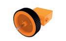
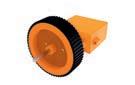
Mechanical parts are like the bones and muscles of a robot. They include wheels, gears, motors, and arms. These parts help the robot move, pick up things, or spin. For example, wheels let a robot roll around, and motors make robots move by turning wheels, spinning gears, or lifting arms.
The electronic parts are like the robot’s brain and nerves. They include circuits, sensors, and batteries. These parts help the robot think and sense its surroundings. Sensors act like eyes, ears, or even a nose for the robot, allowing it to detect light, sound, or obstacles. The battery gives the robot the power it needs to work.
Coding is how we talk to robots and tell them what to do. Coding means writing instructions for them to follow. The coding interface is the program or app used to give these instructions. Once coded, the robot can move in a specific direction, stop when it sees something, or even dance.
By combining these three parts—mechanical, electronic, and coding—robots come to life and do amazing things.


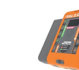
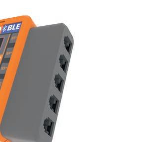
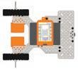
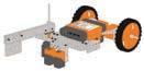
The Robotics Advanced Kit (RAK) is a comprehensive tool for young innovators who are curious to explore the subject of robotics. It features the Robotics FULL 2.0 BLE Brain, which powers the kit's projects. The kit also includes exciting projects, thereby encouraging creativity and problem-solving in students. With hands-on components and coding opportunities, RAK makes robotics fun-filled and accessible, inspiring students to think critically about robotics and innovate its programming. Let us explore its various components.
Electronics Parts


9.
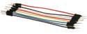
• Long Connecting Cable × 1
• USB Cable × 1
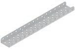
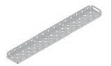
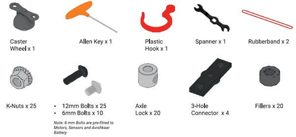
Construction Parts
Plastic Parts


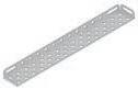

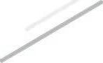


A comprehensive metal design system allows you to make from easy to complex mechanical bot designs.


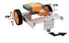
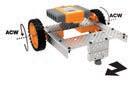
Let's understand how the motors work.
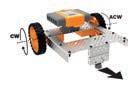
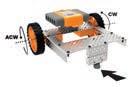
Robots move in different directions by the combination of the rotation from each wheel. For example: Robot Movement

Let's understand some basics of building:
Tightening Screws:


Tightening Axle Lock:


Tightening a Motor to a Plate:


Tighten (Rotate Clockwise)
Loosen (Rotate Anti-Clockwise)


Tighten (Rotate Clockwise)


Loosen (Rotate Anti-Clockwise)

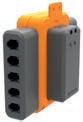

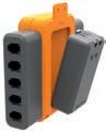
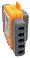


Let's understand how the Full 2.0 Brain works.
Let’s understand how the Full 2.0 BLE Brain works.
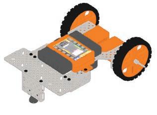
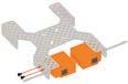
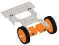
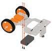
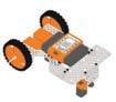
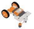
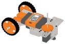
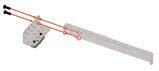
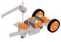
1 Insert the axle lock and the 3.5" axles into the high-speed motors, as shown.
2 After attaching the axles to both motors, screw them to the chassis using the 6mm bolts, as shown.
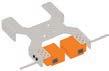
3 Repeat the previous step to attach the second high-speed motor to the other side of the chassis.
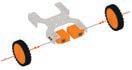
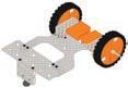
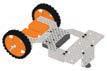
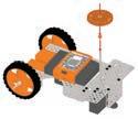
4 Add a filler to the axle, then add the wheel, and, lastly, add another axle lock. Do this for both axles.

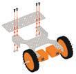
5 Screw a 7.5 inch rectangular plate using 12 mm bolts with the first two holes of both the right and left sides of the chassis.
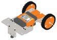
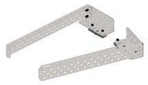
6 Attach two U-Beams, one on top of the other using 6mm bolts. Then, screw the Caster wheel to both U-Beams using 2 K-nuts and 6mm bolts, as shown below.
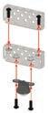

7 Attach the previous assembly to the chassis as shown, with 12 mm bolts.
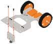
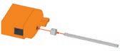
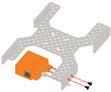
8 Screw the Battery at the bottom of the chassis using 6mm bolts as shown.
9
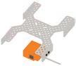
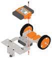
Screw the Brain to the chassis using 6mm bolts. Connect the Brain to the Battery using Male to Male DC Jack wire
10
Connect the left motor to the "M4" port and the right motor to the "M3" port of the Brain using the short connecting cables
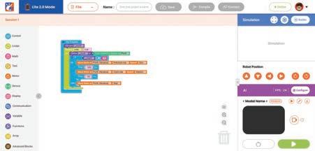
The coding interface serves as the central hub for your kit, acting as an Integrated Development Environment (IDE) that enables you to write code for all of your experiments. This code is then transferred to the hardware.
The coding interface consists of the following components:
1. Workspace Area: This is where you drag blocks for the code you want to write.
2. Blocks Panel: The blocks from the Blocks Panel help make your code.
3. Share Code: The Share Code option in the File drop-down menu generates a link for the project to share with others.
4. Control Buttons: The Control Buttons consist of Save, Compile, and Connect buttons.
• Save Button: The Save button helps save your code.
• Compile Button: The Compile button helps compile your code.
• Connect Button: The Connect button helps burn your code to the hardware.
5. Arena: This is where you can see the output.
6. Buttons: The buttons help move the bot front, back, left, or right. The buttons also help rotate the bot clockwise and anticlockwise in the virtual arena.
7. Play Button: The Play button runs the code.
8. Reset Button: The Reset button resets the arena.
Burning means loading your code into the hardware. This process, mainly, has the phases, as shown:
Arrange the blocks to create the code Save the code
Compile the code Burn the code
In case of error, recheck the code.
1. Once you have completed your experiment, connect the bot to a PC/Laptop using a USB cable or Bluetooth.
2. Save and compile your code by clicking on the Save and Compile buttons, respectively.
3. Now, click on Connect
4. Click on the USB Connect option or the BLE Connect (Bluetooth) option.
5. Click on the Connect Device button, and a small window will appear. Thereafter, select your connected device, and then click on Connect
6. Now, click on Burn to write your program into the bot.
7. You have successfully written your code into the hardware. Now, you can experiment on the bot.
Objective
Learn how to control a robot by making it move forward, backwards, left, and right using motors. This helps in understanding the basics of how robots work and is a great start to learning robotics!
In this experiment, the concept of time delay is used to suspend the execution of a program for a particular time. Let us understand this by looking at the process of cooking a dish in the microwave.
Put the dish in the microwave.
Set the timer of the microwave.
Wait for the buzzer to beep. Is the buzzer beeping?
1. Click on the Control category from the Blocks panel.
Take the dish out.
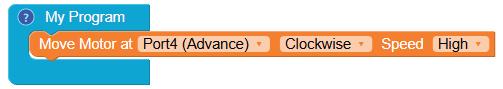
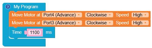
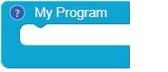
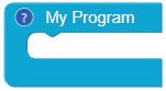
2. Drag the My Program block to the workspace to begin your program.
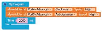
3. Drag the Move Motor at block from the Motor category and drop it inside the My Program block.
4. Configure the motor at Port4 (Advance) as clockwise by selecting the Clockwise option from the drop-down.
5. Select the speed of the motor as High, Medium, or Slow from the Speed drop-down.

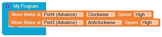
6. Similarly, drag another Move Motor at block and drop it below the previous block.
7. Select the Port3 (Advance) option from the drop-down menu.
8. Configure the motor at Port3 as anticlockwise by selecting the Anticlockwise option from the drop-down menu.
9. Select the speed of your choice from the Speed drop-down menu.
10. Drag the Time block from the Control category and drop it below the second Move Motor at block.
11. Type "2000" in the value box of the block. This will allow the forward movement of the motor for 2000 milliseconds or 2 seconds.
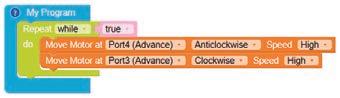
12. To move the bot forward for infinite time, use the Repeat while block from the Loops category with the Move Motor at blocks.

13. Similarly, to turn the bot backwards, configure the motor at Port4 as Anticlockwise and Port3 as Clockwise by making the respective selections from the drop-down menus.
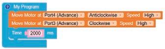
14. To move the bot backwards for infinite time, use the Repeat while block from the Loops category with the Move Motor at blocks.
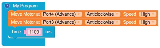
15. To turn the bot to the right, configure the motor at Port4 and Port3 as Anticlockwise and add a delay of 1100 ms by adding a Time block.
16. To turn the bot to the left, configure the motor at Port4 as Clockwise and Port3 as Clockwise too.
Note: When you turn the bot left or right, the time value may vary from system to system. Therefore, to make a 90 degree turn, you can configure the time value accordingly.
17. Give a name to your program, save it, and then compile it.
18. Now, the program is ready to burn on the RAK.
Scan QR code to view output
A. Tick () the Correct Option.
1 Which block is used to start your program?
a My Program
c Begin Program
2 The execution of all the blocks in a code occur
a timely
c in a loop
b Start Program
d Your Program
b step by step
d with delay
3 In which direction should the motors rotate to turn the robot to the left?
a Both motors clockwise
c Left motor clockwise, right motor anticlockwise
B. Answer the Following.
b Both motors anticlockwise
d Left motor anticlockwise, right motor clockwise
1 How should the motors be configured to move the robot in the right direction?
2 What is the use of the "Repeat while" block?
C. Apply Your Learning.
1 Where can you see the applications of a moving robot in daily life?
2 What will happen in your project if you don't use the "Repeat while" block?
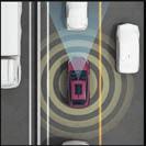
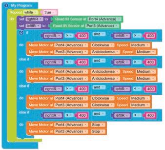
By strategically utilising two IR sensors, the students will program the robot to accurately track and follow a specific line. This activity develops their understanding of sensor-based navigation and improves problemsolving skills in robotics.
The major use of line follower is in Advanced Driver Assistance Systems (ADAS) in cars as Lane Assist.
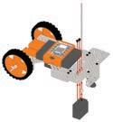
1 Connect the IR Sensor to the lower 2.5" U-Beam of the RC Car using 6mm Bolts.
1. Click on the Control category from the Blocks panel.
2
Similarly, connect another IR Sensor to the U-Beam of the assembly.
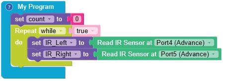
2. Drag the My Program block to the workspace to begin your program. The execution of all the blocks inside this occurs step by step.
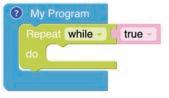
3. Drag the Repeat while block from the Loops category and drop it inside the My Program block to begin the infinite loop. This block is set to true by default.
4. Click on the Variables category.
5. Click on the Create Variable button. A pop-up box appears.
• Enter a suitable variable name, such as "rightIR".
• Click on the OK button. This will create a variable to store the data of the IR sensor value received from the right IR sensor.
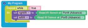
6. Drag the set rightIR to block from the Variables category and drop it inside the Repeat while block.
7. Then, drag the Read IR Sensor at block from the Sensor category and drop it next to the set rightIR to block. Configure this block to Port4 (Advance)
8. Now, similarly create another variable named "leftIR".
9. Drag and drop the set leftIR to block. To its right, drag and drop the Read IR Sensor at block. Configure this block to Port5 (Advance).
10. Drag the if block from the Control category and drop it below the set leftIR to block.
11. Click on the settings icon of the if block. A pop-up box appears.
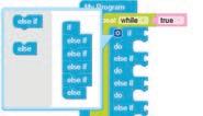
12. Drag the else if block three times and place them below the if block in the pop-up box (refer to the given image).
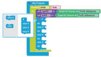
13. Now, click on the settings icon again to close the pop-up box.
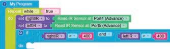
14. Drag the block from the Control category and attach with the if block.


15. Drag two blocks from the Control category and drop them inside the left and right boxes of the block.
16. Select the '>' sign in place of the '=' sign for both the blocks.
17. Drag the rightIR block from the Variables category and drop it in the left value box of the block.

18. Drag and drop the block from the Math category inside the right value box of the block. Type '400' in place of '0'.
19. Similarly, set the condition of the leftIR variable.

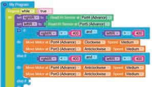
20. If the value of the rightIR and leftIR is greater than 400, i.e., both the IR sensors detect the white lines, then, blocks under this if block will be executed.
21. For the if part, configure the motors at Port4 (Advance) to Clockwise direction and Port3 (Advance) to Anticlockwise direction. This will instruct the bot to keep moving forward when it is on top of the black line.
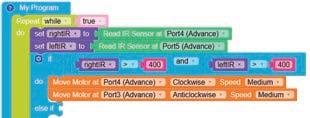
22. Similar to defining the condition for the if block, define the condition for the first else if part. Set the rightIR value as less than 400 and set the leftIR value as greater than 400. The code under this else if part will execute when the right IR sensor detects the black line below.
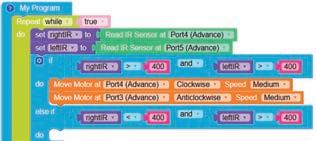
23. For the first else if part, set both motors to turn right. For this, configure the motors at Port1 and Port2 as Anticlockwise. This will instruct the bot to turn right as long as the right IR sensor is on top of the black line.
24. For the second else if part, use the comparison blocks to set the rightIR value as greater than 400 and set the leftIR value as less than 400. The code under this else if part will execute when the left IR sensor detects the black line below.
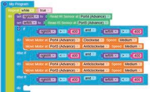
25. For the second else if part, set both motors to turn left by configuring the motors at Port1 and Port2 as Clockwise. This will instruct the bot to turn left as long as the left IR sensor is on top of the black line.
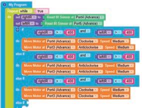
26. For the third else if part, use the comparison blocks to set the rightIR value as less than 400 and set the leftIR value as less than 400. The code under this else if part will execute when both the left and right IR sensors detect the black line below.
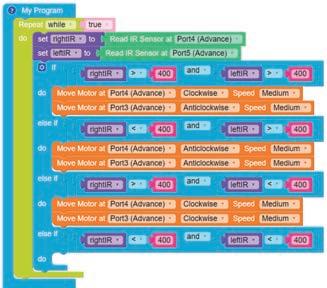
27. For the third else if part, set both motors to Stop. This will instruct the bot to stop if both the sensors detect the black line below.
28. Give a name to your program, save it, and then compile it.
29. Now, the program is ready to burn on the RAK.
Scan QR code to view output
A. Tick () the Correct Option.
1 What value indicates that an IR sensor has detected a white line?
a Less than 200
c Exactly 300
b Greater than 400
d Less than 100
2 When both IR sensors detect the black line, what action does the bot perform?
a Moves forward
c Turns left
B. Answer the Following.
1 Why are two IR sensors used in the line following bot?
b Turns right
d Stops
2 What is the purpose of using variables like rightIR and leftIR in the code?
C. Apply Your Learning.
1 Imagine your bot detects a white line with only the right IR sensor. Describe what the bot should do to stay on the line.
2 If you want the bot to turn left only when the left IR sensor detects the black line, how would you set up the motors?
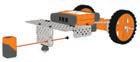
Learn how to program a bot to pick and place things from one place to another.
1 Connect the High Torque Motor to the 7.5" Rectangle in the RC Car assembly using Bolts, a 3.5" Axle, and an Axle Lock.
2 Insert a Filler and then a Big Spur Gear in the Axle of the assembly.
3 Insert an Axle in the 7.5" Rectangle in the assembly and tighten the connection using an Axle Lock. Insert a Filler and Big Spur Gear in the Axle.
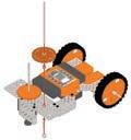
4 Connect the 2.5" L-Channel to a 3-Hole Connector using 12mm Bolts and K-Nuts.

5 Connect the 2.5" L-Channel in the previous assembly to a 7.5" U-Beam using Nuts and Bolts

6 Similarly, create another assembly by following steps 4 and 5 again.
7 Now, insert the 2.5" L-Channel (from one of the assemblies in the previous step) into one of the Axles in the assembly from step 3 and tighten the connection using an Axle Lock.
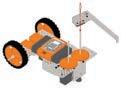
8 Repeat the previous step to form the assembly for the Gripper Bot.
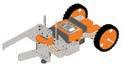
The gripper bots can be used as industrial robots and to perform a variety of other tasks.
Let's Code
1. Click on the Control category in the Blocks panel.
2. Drag the My Program block to begin your program. The execution of all the blocks present inside this occurs step by step.

3. Click on the Variables category.
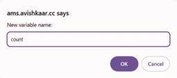
• Click on the Create variable button. A pop-up box will appear asking you to enter a new variable name.
• Enter a suitable variable name, let us say "count".
• Click on the OK button.
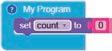
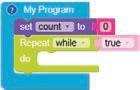
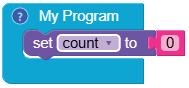
4. Drag the set to block from the Variables category and drop it inside the My Program block.
5. Now, drag the Number block from the Math category and attach it to the set to block. The value of the Number block is set to "0" by default.
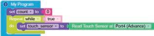
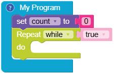
6. Drag the Repeat while block from the Loops category and drop it below the set to block.
7. Now, create another variable, named "touch_sensor".
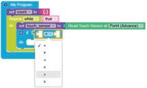
8. Drag the set (touch sensor) to block from the Variables category and drop it inside the Repeat while block.
9. Now, drag the Read Touch Sensor at block from the Sensor category and attach it to the set to block. Select Port4 (Advance) from the drop-down menu.
10. Now, drag the if block from the Control category and drop it below the set to block.
11. Drag the equal operator block from the Control category and attach it to the if block.
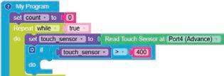
12. Select the '>' option from the drop-down menu of the equal operator block.
13. Drag the touch_sensor block from the Variables category and drop it in the left part of the greater than operator block.
14. Now, drag the number block and drop it in the right part of the greater than operator block. Type "400" in the text part of the number block.
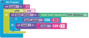
15. Now, drag the set to block and drop it in the do part of the if block. Select the count variable from the drop-down menu of the set to block.
16. Drag the add operator block from the Math category and attach it to the set to block.
17. Now, drag the count variable block and drop it in the left part of the add operator block. This adds a sum of "1" to the variable count every time the touch sensor is pressed.
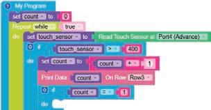
18. Now, drag the Print Data block from the Display category and drop it below the set to block.
19. Drag the count variable block and drop it in the empty part of the Print Data block. Set the row as Row3 from the drop-down menu.
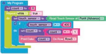
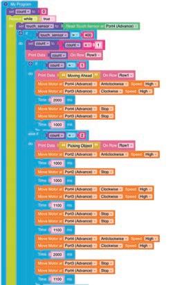
20. Now, drag the if block from the Control category and drop it below the Print Data block.
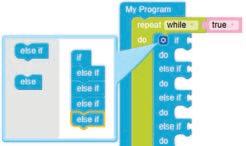
21. Click on the settings icon of the if block. A pop-up box will appear.
22. Drag the else if block and drop it below the if block in the pop-up box. Repeat this three times (refer to the image below).
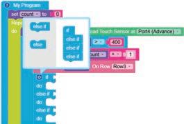
23. Click on the settings icon again to hide the pop-up box.
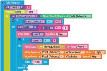
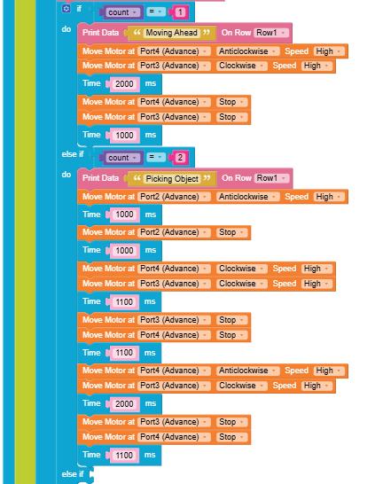
24. Now, define the condition for the if block using the equal operator block from the Control category. If the value of the count variable equals "1", then blocks under the if block will be executed, otherwise the blocks under one of the else if blocks will be executed.
25. Now, drag the Print Data block from Display category and drop it in the do part of the if block.
26. Drag the Text Box block from the Text category and drop it in the empty part of the Print Data block. In the Text Box block, type "Moving Ahead".
27. Drag and drop two Move Motor at blocks below Print Data block.
28. Configure the motor at Port4 (Advance) as anticlockwise by selecting the Anticlockwise option from the drop-down menu. Select the Speed of the motor as High
29. Similarly, select Port3 (Advance) from the drop-down menu of the second Move Motor at block. Configure its motor as clockwise by selecting the Clockwise option from the drop-down menu. Select the Speed of the motor as High.
30. Drag the Time block from the Control category and drop it below the second Move Motor at block.
31. Type "2000" in the value box of the block. This will allow the movement of the motor for 2000 milliseconds or 2 seconds.
32. Similarly, drag two Move Motor at blocks and configure the motors at Port4 (Advance) and Port3 (Advance) to Stop. This will instruct the bot to stop.
33. Drag and drop another Time block below the Move Motor at block. The block is set to 1000 milliseconds or 1 second by default.
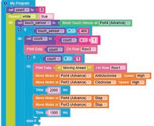
34. Similarly, set conditions for "Picking Object" in the first else if block as shown in the figure below.
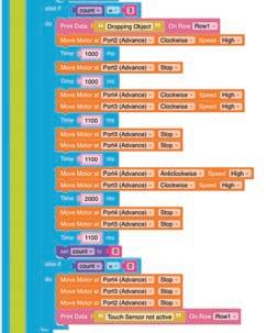
35. Similarly, set conditions for "Dropping Object" in the second else if block as shown in the figure below.
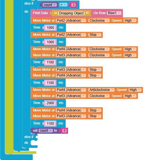
36. Similarly, set conditions for the third else if block as shown in the figure below.
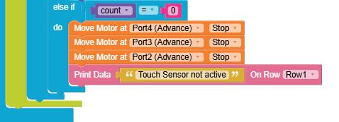
37. The complete code will look like the figures below.
38. Give a name to your program, save it, and then compile it.
39. Now, the program is ready to burn on the RAK.
Note: The RAK should be connected to your computer through Bluetooth or a USB cable for the experiment to run.
Scan QR code to view output
A. Tick () the Correct Option.
1 In which category would you find the "add" operator block?
a Math b Control
c Button d Display
2 In the if block, which operator is used to compare the value of the touch sensor with 400?
a < b >
c = d <=
3 In the code, which port is selected for the "Read Touch Sensor at" block?
a Port2 (Advance)
c Port4 (Advance)
B. Answer the Following.
1 What are variables?
b Port3 (Advance)
d Port1
2 What is the role of the touch sensors?
C. Apply Your Learning.
1 What will happen if you do not add the 'Time' block after the 'Move Motor at' block?
2 Give one real-life application of a gripper bot.
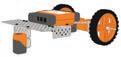
Learn to program the bot to skilfully track and follow a designated line using two IR sensors, thereby enhancing understanding of sensor-based navigation and improving problem-solving abilities in robotic applications. Objective
Industrial Robots

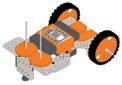
1 Connect the IR Sensor to the lower 2.5" U-Beam of the RC Car using 6mm Bolts. Let's Build
2 Similarly, connect another IR Sensor to the U-Beam of the assembly.
3 Connect the High Torque Motor to the 7.5" Rectangle in the assembly using a 3.5" Axle, an Axle Lock, and 12mm Bolts
4 Connect the 7.5" U-Beam to the 3-Hole Connector using 12mm Bolts and K-Nuts.
5
Connect the 2.5" Square Plate to the U-Beam in the assembly from the previous step using Nuts and Bolts

6
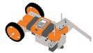
Connect the Axle in the assembly from step 3 to the U-Beam in the assembly from the previous step using an Axle Lock and Fillers. This will complete the assembly as shown.
Let's Code
1. Click on the Control category in the Blocks panel.
2. Drag the My Program block to begin your program. The execution of all the blocks present inside this will occur step by step.
3. Click on the Variables category.
• Click on the Create variable button. A pop-up box will appear asking you to enter a new variable name.
• Enter a suitable variable name, let us say "count".
• Click on the OK button.

4. Drag the set to block from the Variables category and drop it inside the My Program block.
5. Now, drag the Number block from the Math category and attach it to the set to block. By default, the value is set to "0".
6. Drag the Repeat while block from the Loops category and drop it below the set to block to begin the infinite loop. The loop value is set to true by default.
7. Now, create two other variables, namely, IR_Left and IR_Right
8. Drag the set to block from the Variables category and drop it inside the Repeat while block. Select IR_Left from the drop-down menu of the set to block.
9. Now, drag the Read IR Sensor at block from the Sensor category and attach it to the set to block. Select Port4 (Advance) from the drop-down menu.
10. Drag another set to block and drop it below the previous set to block. Select IR_Right from the drop-down menu of the set to block.
11. Similarly, drag another Read IR Sensor at block and attach it to the set to block. Select Port5 (Advance) from the drop-down menu.
12. Now, drag the Print Data block from the Display category and drop it below the second set to block. Select Row3 from the drop-down menu of the Print Data block.
13. Drag the count block from the Variables category and drop it in the empty part of the Print Data block.
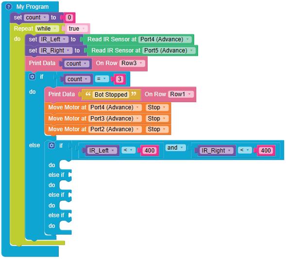
14. Now, drag the if block from the Control category and drop it below the Print Data block.
15. Click on the settings icon of the if block. A pop-up box will appear.
16. Drag the else block and drop it below the if block in the pop-up box (refer to the image below).
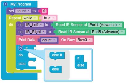
17. Click on the settings icon again to hide the pop-up box.
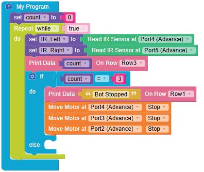
18. Drag the equal operator block from the Control category and attach it to the if block.
19. Drag the count block from the Variables category and drop it in the left part of the equal operator block.
20. Now, drag the number block from the Math category and drop it in the right part of the equal operator block. Type "3" in the text part of the number block.
21. Now, drag the Print Data block and drop it in the do part of the if block.
22. Drag the Text Box block from the Text category and drop it in the empty part of the Print Data block. In the Text Box block, type "Bot Stopped".
23. Drag three Move Motor at blocks from the Motor category and drop them below the Print Data block. Configure the motors at Port4 (Advance), Port3 (Advance), and Port2 (Advance) to Stop.
24. Now, drag three Move Motor at blocks from the Motor category and drop them below the Print Data block. Configure the motors at Port4 (Advance), Port3 (Advance), and Port2 (Advance) to Stop the three motors.
25. Now, define the condition for the else block. Drag the if block from the Control category and drop it inside the else condition.
26. Click on the settings icon of the if block. A pop-up box will appear.
27. Drag the else if block and drop it below the if block in the pop-up box. Repeat this three times (refer to the image below).
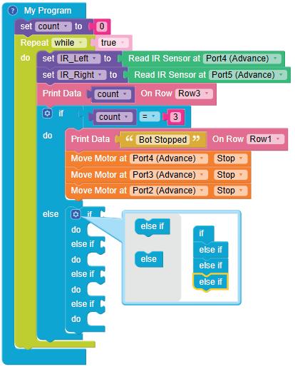
28. Click on the settings icon again to hide the pop-up box.
29. Drag the and operator block from the Control category and attach it to the if block.
30. Now, drag two equal operator blocks and drop one block to the left of the and block and drop another block to the right of the and bock.
31. Select the '<' operator from the drop-down list of both the two equal operator blocks.
32. Drag the IR_Left block from the Variables category and drop it in the left value box of the left '<' block.
33. Drag the number block from the Math category and drop it in the right value box of the left '<' block. Type "400" in place of "0".
34. Similarly, drag the IR_Right block from the Variables category and drop it in the left value box of the right '<' block.
35. Drag the number block and drop it in the right value box of the right '<' block. Type "400" in place of "0".
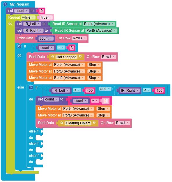
36. Now, drag the set to block from the Variables category and drop it in the do part of the if block. Select the count variable from the drop-down menu of the set to block.
37. Drag the add operator block from the Math category and attach it to the set to block.
38. Now, drag the count variable block and drop it in the left part of the add operator block. This adds a sum of "1" to the count variable.
39. Drag two Move Motor at blocks from the Motor category and drop them below the set to block. Configure the motors at Port4 (Advance) and Port3 (Advance) to Stop
40. Now, drag the Print Data block from the Display category and drop it below the Move Motor at block.
41. Drag the Text Box block from the Text category and drop it in the empty part of the Print Data block. In the Text Box block, type "Clearing Object".
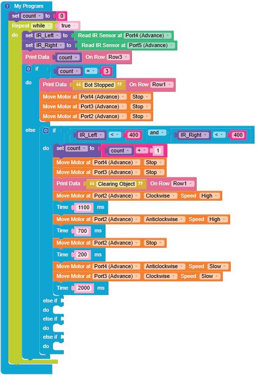
42. Drag and drop the Move Motor at block below the Print Data block.
43. Configure the motor at Port2 (Advance) as clockwise by selecting the Clockwise option from the dropdown menu.
44. Drag the Time block from the Control category and drop it below the Move Motor at block.
45. Type "1100" in the value box of the block. This will allow the movement of the high-torque motor in the clockwise direction for 1100 milliseconds.
46. Similarly, configure the motor at Port2 (Advance) as Anticlockwise. To make the high-torque motor move Anticlockwise for 700 milliseconds, use the Time block.
47. Now, configure the high-torque motor to Stop for 200 milliseconds.
48. Now, configure the motors at Port4 (Advance) and Port3 (Advance) as Anticlockwise and Clockwise, respectively.
49. Set the Time block to 2000 milliseconds. This will make the bot move backwards for 2000 milliseconds or 2 seconds.
50. Similarly, set conditions for the first else if block. If both the IR Sensors are active, the blocks under the first else if block will be executed. This will make the bot move backwards and stop the high-torque motor.
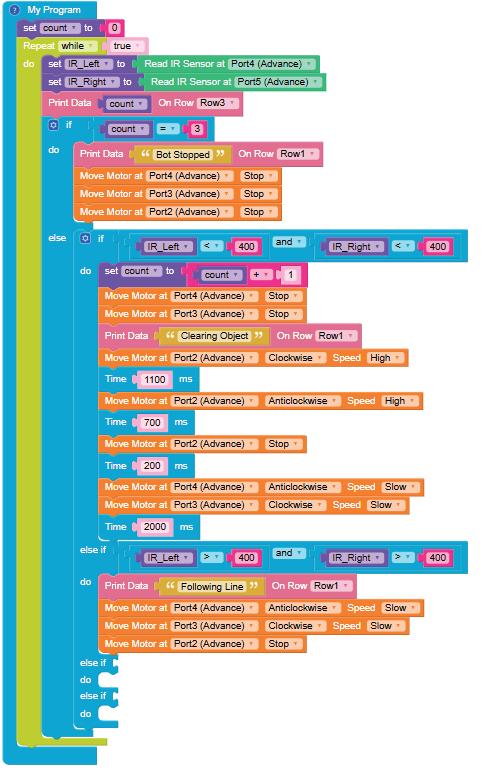
51. Similarly, set conditions for the second else if block. If only the right IR Sensor is active, the blocks under the second else if block will be executed. This will make the bot move right and stop the high-torque motor.
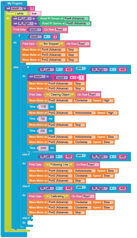
52. Similarly, set conditions for the third else if block. If only the left IR Sensor is active, the blocks under the third else if block will be executed. This will make the bot move left and stop the high-torque motor.
53. Give a name to your program, save it, and then compile it.
54. Now, the program is ready to burn on the RAK.
Note: The RAK should be connected to your computer through Bluetooth or a USB cable for the experiment to run.
Scan QR code to view output
A. Tick () the Correct Option.
1 What are the names for the IR sensor variables in this program?
a count and touch_sensor
c IR_Left and IR_Right
2 In the 'if ' block, what condition is used to stop the bot?
a count < 2
c IR_Left = IR_Right
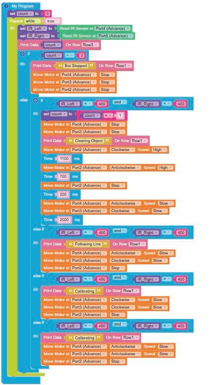
3 What happens when both the IR sensors become active?
a The bot moves right.
c It stops immediately.
B. Answer the Following.
1 Why do we use the "Repeat while" block?
2 What is the role of the variable 'count' in the program?
C. Apply Your Learning.
2 Give one real-life application of a sweeper line follower. Exercise
b motor and sensor_data
d Port4 and Port5
b count = 3
d count = 0
b It adds 1 to the count variable and displays "Clearing Object."
d The bot moves backwards and the high-torque motor stops.
1 In a warehouse, how can you ensure the bot avoids colliding with other bots while following a line?
Objective
Design a robot to grab, pick up, and place things in another, either by using AI speech recognition mode or camera capture mode.
Artificial Intelligence, or AI, is the field of computer science that deals with the study of the principles, concepts, and technology for building machines that can think, act, and learn like humans. Machines possessing AI should be able to mimic human traits like making decisions, recognising patterns, predicting outcomes based on certain actions, learning, and improving on their own.
NLP is a domain of AI that enables computers to understand human language and generate appropriate responses when we interact with them. It allows computers to talk to us in a way that feels natural to us. Popular examples of NLP applications include Google Assistant, Siri, Alexa, Google Translate, etc.
Computer Vision is a domain of AI which uses cameras to see and understand visual information.
Things Around Us
Some real-life examples of NLP are:


1. Face Recognition in Smartphones 2. Self-driving Cars


In this experiment, the use of NLP in the RAK bot includes:
• Recognising spoken commands such as "arm", "forward", "backward", "left", and "right".
• Converting spoken commands into actions that the RAK can execute.
• Detecting user input that is not clear and prompting the user to repeat the commands.
1. Click on the Control category in the Blocks panel.
2. Drag the My Program block to begin your program. The execution of all the blocks present inside this occurs step by step.
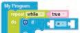
3. Drag the repeat while block from the Loops category and drop it inside the My Program block to begin the infinite loop. The loop value is set to true by default.
4. Click on the Variables category.
• Click on the Create variable button. A pop-up box appears asking you to enter a new variable name.
• Enter a suitable variable name, let us say "Speech".
• Click on the OK button.


5. Drag the set to block from the Variables category and drop it inside the repeat while block.
6. Drag the get recognised speech block from the Speech Recognition category and attach it to the set to block.
7. Now, drag the if block from the Control category and drop it below the set to block.
8. Click on the settings icon of the if block. A pop-up box appears.

9. Drag the else if block and drop it below the if block in the pop-up box. Repeat this four times (refer to the image below).
10. Click on the settings icon again to hide it.
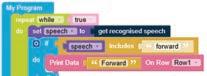
11. Now, drag the includes block from the Text category and attach it to the if block.
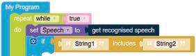
12. Drag the Speech block from the Variables category and drop it in the left text box of the includes block.
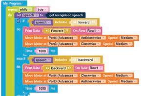
13. Type "forward" in the right text box of the includes block.
14. Now, drag the Print Data block from the Display category and drop it in the do part of the if block.
15. Drag the Text Box block from the Text category and drop it in the Print Data block. In the Text Box block, type "Forward".
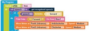
16. Now, drag the Move Motor at block from the Motor category and drop it below the Print Data block.
17. Configure the motor at Port4 (Advance) as anticlockwise by selecting the Anticlockwise option from the drop-down.
18. Select the speed as Medium from the Speed drop-down menu.
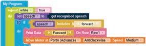

19. Again, drag the Move Motor at block from the Motor category and drop it below the first Move motor at block.
20. Configure the motor at Port3 (Advance) as clockwise by selecting the Clockwise option from the drop-down.
21. Select the speed as Medium from the Speed drop-down menu.
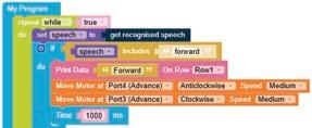
22. Drag the Time block from the Control category and drop it below the second Move Motor at block.
23. Type "1000" in the value box of the block. This will allow the forward movement of the motor for 1000 milliseconds or 1 second.
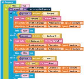
24. Similarly, set conditions for "backward" in the first else if block as shown in the figure below.
25. Similarly, set conditions for "turn" in the second else if block as shown in the figure below.
26. Similarly, set conditions for "pick" in the third else if block as shown in the figure below.
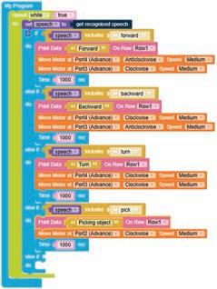
27. Similarly, set conditions for "drop" in the fourth else if block as shown in the figure below.
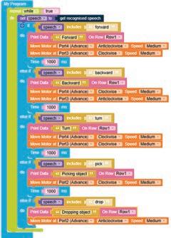
28. Give your program a name, save it, and then compile it.
29. Now, the program is ready.
Note: The RAK should be connected to your computer through Bluetooth or a USB cable for the experiment to run.
30. Click on the Run button in the AI window.
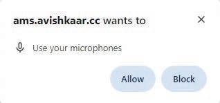
31. Allow the system to use your microphone to hear your commands.
32. Click on the microphone button in the AI window.
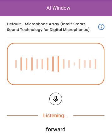
33. Give any command (forward, backward, turn, pick, or drop). Here, the AI detects the voice as "forward".
34. Again, click on the microphone button and observe the output.
In this experiment, computer vision is used to recognise hand gestures using the camera.
• The AI model is trained to detect specific handposes, such as a palm, fist, and fingers.
• Once trained, the model can identify these gestures in real-time.
• Each gesture then triggers specific actions in the game, such as moving forward, backward, turning left, or turning right.
• This allows players to control the bot with their hand movements.
Instructions
Before we start writing the code, let us train our AI Model. Follow the given steps:
1. Allow the system to use your camera.
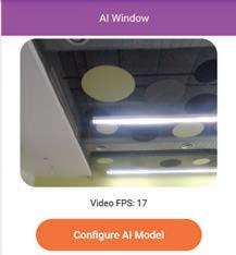
2. Click on the Configure AI Model button in the AI Window on the right of your screen.
3. Choose your model by selecting Handpose from the Create Your Model pop-up window.

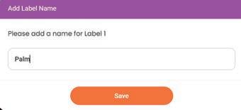
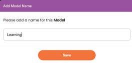
4. Add a name for your model and save it. You can also skip it.

5. Now, add the label name as "Palm" and click on the Save button.
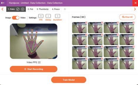
6. Click on the Start Recording button and show your palm up to 60 Frames on the camera.
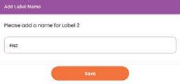
7. Now, click on the Plus sign in the top left corner and add a name for Label 2. Here, the name of Label 2 is "Fist". Then, click on the Save button.
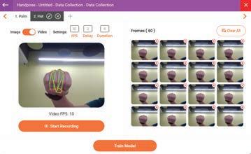
8. Similarly, show your fist on the camera and record different fist postures by showing your fist on the camera.
9. Similarly, add other labels such as "Peace", "Thumbs up", and "Thumbs down".
10. Now, click on the Train Model button to train the AI on the recorded handposes. It will take a few minutes.


11. Add an appropriate model name and save it.
12. Test your model to check whether the AI is able to recognise the gestures correctly.
13. Now, click the Download button.
14. You are now ready to write your code.
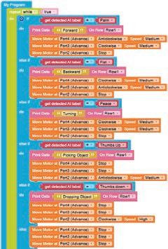
1. Click on the Control category in the Blocks panel.
2. Drag the My Program block to begin your program. The execution of all the blocks present inside will occur step by step.
3. Drag the repeat while block from the Loops category and drop it inside the My Program block to begin the infinite loop. The loop value is set to true by default.
4. Now, drag the if block from the Control category and drop it inside the repeat while block.
5. Click on the settings icon of the if block. A pop-up box appears.
6. Drag the else if block and drop it below the if block in the pop-up box. Repeat this four times. Drag the else block and drop it below the last else if block. (refer to the image below).
7. Click on the settings icon again to hide the pop-up box. Let's Code


8. Drag the equal operator block from the Control category and attach it to the if block.
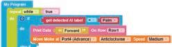
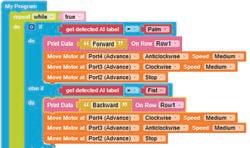
9. Now, drag the get detected AI label block from the AI category and drop it in the left part of the equal operator block.
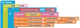
10. Drag the Palm block from the AI category and drop it in the right part of the equal operator block.
11. Now, drag the Print Data block from the Display category and drop it in the do part of the if block.
12. Drag the Text Box block from the Text category and drop it in the Print Data block. In the Text Box block, type the text "Forward".
13. Now, drag the Move Motor at block from the Motor category and drop it below the Print Data block.


14. Configure the Motor at Port4 (Advance) as anticlockwise by selecting the Anticlockwise option from the drop-down.
15. Select the speed as Medium from the Speed dropdown menu.
16. Again, drag the Move Motor at block from the Motor category and drop it below the first Move motor at block.
17. Configure the Motor at Port3 (Advance) as clockwise by selecting the Clockwise option from the drop-down.
18. Select the speed as Medium from the Speed drop-down menu.
19. Again, drag the Move Motor at block from the Motor category and drop it below the second Move Motor at block.
20. Configure the Motor at Port2 (Advance) as stop by selecting the Stop option from the drop-down.
21. Similarly, set the conditions for "Fist" in the first else if block as shown in the figure below.

22. Similarly, set the conditions for "Peace" in second else if block as shown in the figure below.
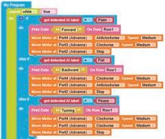
24. Similarly, set the conditions for "Thumbs down" in the fourth else if block as shown in the figure below.
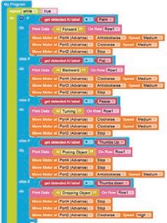
23. Similarly, set the conditions for "Thumbs Up" in third else if block as shown in the figure below.
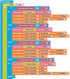
25. Now, let us set the conditions for the else block as shown in the figure below.
26. Give your program a name, save it, and then compile it.
27. Now, the program is ready.
Note: The RAK should be connected to your computer through Bluetooth or a USB cable for the experiment to run.
28. Click on the Run button in the AI window.
29. Show any pose (Palm, Fist, Peace, Thumbs up, or Thumbs down) on the camera.
30. Observe the output. Scan QR code to view output
A. Tick () the Correct Option.
1 Which AI domain is used to convert spoken commands into actions on the RAK?
a Machine Learning
c Computer Vision
b Natural Language Processing
d Data Science
2 Which block is used to display a message like "Forward" or "Backward" on the screen?
a includes
c Print Data
3 What gesture will make the bot move forward?
a Fist
c Peace
B. Answer the Following.
b get recognised speech
d Move Motor
b Palm
d ThumbsUp
1 What is the purpose of Natural Language Processing (NLP) in this experiment?
2 Explain the role of the "Move Motor at" block in controlling the bot.
1 How would you modify the code to adjust the speed to slow down the robot's movements for more precise control during pick-and-place tasks?
2 If the robot does not respond to the "forward" command, which part of the program should you check first for troubleshooting?


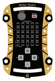

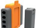
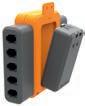
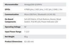
Maker Board is an easy-to-use electronic platform that helps you to make innovative projects. It consists of a 5×5 RGB LED matrix, a buzzer, four push buttons and six GPIO pins.
You can use your creative ideas using the Maker Board by controlling its electronic sensors and modules. You can make and play interactive games using the LED matrix and the push buttons. You can make a piano, a snake game, a smart band, and many more such things.
The Maker Board robotics kit contains the following components:


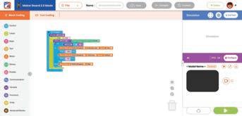
The Maker Board can be programmed using the Maker Studio coding interface, an easy-to-use Graphical User Interface (GUI) block-based coding platform.
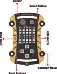
1. GPIO Pads
There are 4 Pulse Width Modulation (PWM) pins and 2 Analog to Digital Converter (ADC) pins, which make a total of 6 General Purpose Input Output (GPIO) pins to interface with analog and digital sensors, LEDs, Motors, etc., using jumper cables and alligator clips.
2. Power Pins
1 VCC pin—This pin outputs a regulated voltage of 3.3V.
2 GND pins—Power Output (0V).
1 VIN pin—The input voltage to the Maker Board when it is using an external power source.
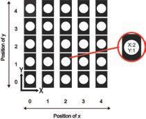
3. Programming LED Matrix
An LED matrix is a grid of addressable Red, Green, and Blue (RGB) LEDs arranged in rows and columns. In this, a total of 25 addressable RGB LEDs are used, which can be controlled individually. An LED matrix can be used to display animations or scroll text, numbers, patterns, etc. It can also be used to make different types of 8-bit games.
4. Push Buttons
There are 4 on-board push buttons named A, S, W, and D to perform various operations like activate, deactivate, or move the blinking light of the LED in different directions.
5. Buzzer
The buzzer is used to make different types of sounds at distinct frequencies and at different beats per minute.
6. Reset Button
The reset button is used to restart any program loaded in the Maker Board.
7. Bluetooth Module (HC-05)
The Bluetooth module gets you started with the possibilities of IoT and enables wireless controlling of various equipment connected to the Maker Board.
IoT stands for Internet of Things which refers to a network of interconnected devices embedded with sensors and software, enabling them to collect, exchange data, and make autonomous decisions.
8. Standoff Holes
These holes are present to ensure that the Maker Board can be safely used on electrically conductive surfaces.
The Maker Studio coding interface acts as an integrated development environment that allows you to write code for all of your projects. This code is then loaded into the Maker Board.
The Maker Studio coding interface consists of five major components:
1. A workspace area to drag blocks for the code you want to create.
2. A blocks panel, which contains all the blocks required to make your code.
3. The Share Code option in the File drop-down menu generates a shareable link for the project.
4. Buttons to save, compile, and burn your code.
5. The Simulator Window to see the output.
Burning means loading your code into the Maker Board hardware. This process, mainly, has the following phases:
Arrange the blocks to create the code Save the code
Compile the code Burn the code
In case of error, recheck the code.
Let’s make a program to understand the programming of variables and display counting till 10 on the Maker Board.
Variables
• In coding, variables are objects that can be manipulated rather than just a placeholder for an unknown value.
• Variables are used to store information to be referenced and manipulated in a computer program. They also provide a way of labelling data with a descriptive name, so our programs can be understood more clearly by the reader and ourselves.
• Consider variables as containers that hold information. Their sole purpose is to label and store data in memory. This data can then be used throughout your program.


Some of the real-life examples are:


1. Click on the Control category from the Blocks panel.
2. Drag and drop the My Program block to begin your program. The execution of all the blocks present inside this occurs step by step.
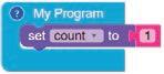
3. Now, create a variable named "count" using the Variables category and set its value to 1.
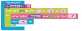
4. Drag the count with block having the value of "i" variable from 1 to 10 skipped by 1.
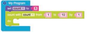

5. Display the value of "i" variable using the show number block from the Display category. Choose the colour of your choice from the colour palette. Set the brightness to 100.
6. Drag and drop the wait block from the Control category and type 700 in the value box.
7. Give a name to your program, save it, and then compile it.
8. Now the program is ready to burn on the Maker Board, and you can use your digital display. Note: The Maker Board should be connected to your computer through a USB for the experiment to run.
Scan QR code to view output
A. Tick () the Correct Option.
1 In coding, variables are used to: a Display information only b Store and label data
c Only store numbers d Create images
2 What block do you use to start the program in the Maker Board?
a Show number block b Wait block
c My Program block d Variables block
3 Which block can be used to set a pause time of 700 milliseconds?
a My Program block
b Wait block
c Display block d Variables block
B. Answer the Following.
1 What is the purpose of variables in coding?
2 Why should you connect the Maker Board to your computer using a USB?
C. Apply Your Learning.
1 Name three real-life examples of variables. How is each one used to store or display data?
2 Write the steps you would take to make a program count to 5 on the Maker Board instead of 10.
Let’s make the Maker Board do some math and make a calculator. We will perform +, −, *, and / operations on numbers depending upon which "W", "A", "S", and "D" keys is pressed by the user. We will use a Maker Board for displaying the numbers.
1. Button-click
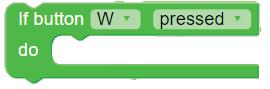
• Button-click is an event that causes something to happen.
• We can use these to tell programs under what circumstance(s) a particular action or set of actions should happen.
• As per input/output system, buttons are considered as input and corresponding actions are considered as output.
2. Conditionals
• Human beings (and other animals) make decisions all the time that affect their lives, for example,
a. "Should I eat one cookie or two?"
b. "Should I play cricket or badminton?"
• Similarly, to make decisions and carry out actions accordingly in our code, we use Conditionals.
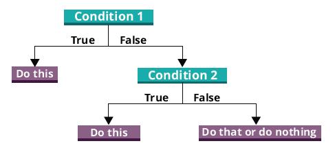
3. If block
• Conditional blocks have conditions, and the program’s flow is based on whether the condition is true or false.
• To apply conditions in code, use the if block. The if block has else if and else blocks.
• If the condition given in the if block is true, then the set of code is executed; otherwise, the code given in else if or else block is executed.
4. Functions
• A function is a reusable block of code designed to perform a specific task. It takes input, processes it, and returns an output. Functions help structure code, reduce repetition, and make programs more readable.
• Functions can be defined using the to do something block from the Functions category. All blocks placed inside this block collectively form the function definition.
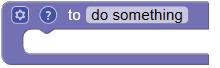
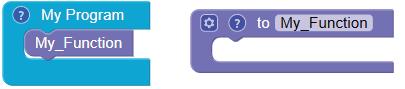
• You can type a suitable name for the function, such as "My_Function", in the text part of the block.
• Since the My Program block is where the execution of all the blocks begins step by step, the function must be called inside the My Program block.
Some real-life examples are:


Code
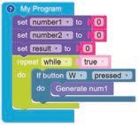
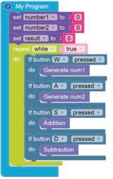
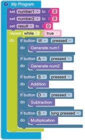
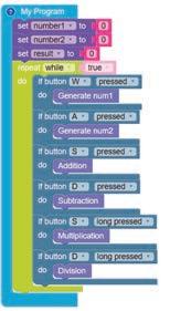
1. Click on the Control category from the Blocks panel.
2. Drag and drop the My Program block to begin your program. The execution of all the blocks present inside this occurs step by step.
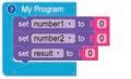
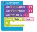
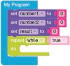
3. Create three variables named number1, number2, and result, and set their values to 0 using the Variables category. Drag and drop the set to block for all three variables, as shown in the figure here.
4. Drag and drop the repeat while block from the Loops category.
5. Create a function named "Generate num1" using the Functions category and increase the value of the number1 variable by 1 to get the desired number using the Variables category. Display the value of the number1 variable using the show number block from the Display category.
6. To create a function, click on the Functions category and drag the to block. Replace the do something with the desired function name. The function will be created.
Note that functions are not set within the code. They are placed separately in the workspace. You can reuse it by calling the function name in your code.
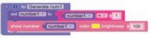
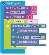
7. Drag the If button block and select W key from the Button category and call the function "Generate num1".
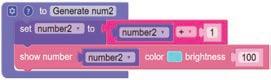
8. Create a function named "Generate num2" and increase the value of number2 variable value by 1 to get the desired number and then display it.
Note: You can create a new function from an existing one by right-clicking and selecting ‘duplicate’. Then you can change the function name and other values in the value box as per your requirements.
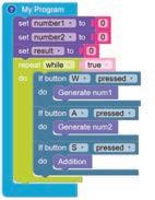
9. Drag the If button block and select A key from the Button category and call the function "Generate num2".
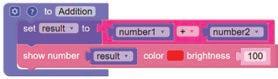
10. Create a function named "Addition" and set the value of the variable result to the addition of number1 and number2 and show the result on the matrix.
11. Drag the If button block and select S key, then call the function "Addition".
Note: Within the workspace, you can duplicate the same block and change its value as per your requirements.
12. Create a function named "Subtraction" and set the value of the result to subtraction of number1 and number2 based on which number is greater and show the result on the matrix using the if and else blocks.
13. If the conditional statement of the if block is false, then the statement(s) of the else block will be executed.
14. You can get the else block by clicking on the settings icon of the if block. A pop-up box appears.
15. Drag the else block and drop it below the if block in the pop-up box.
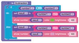
16. Drag the If button block and select D key, then call the function "Subtraction".
17. Create a function named "Multiplication" and set the value of the result to the multiplication of number1 and number2 and show the result on the matrix.
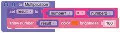
18. Drag the If button block and select S key, then call the function "Multiplication" on long press.
19. Create a function named "Division" and set the value of the result to the division of number1 and number2 and show the result on the matrix.
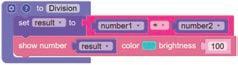
20. Drag the If button block and select D key, then call the function "Division" on long press.
21. Give a name to your program, save it, and then compile it.
22. Now the program is ready to burn on the Maker Board, and you can use your calculator.
Note: The Maker Board should be connected to your computer through a USB for the experiment to run.
Scan QR code to view output
A. Tick () the Correct Option.
1 What is the main purpose of the "button-click" event in this project?
a To display the result on the Maker Board
b To set the variables to zero
c To trigger specific actions based on user input
d To create a conditional block
2 Which key is used to trigger the addition operation in this project?
a W b A
c S d D
3 What is the role of a conditional block in this project?
a To store values of variables
b To create loops for the program
c To decide the flow of the program based on true or false conditions
d To call functions in the workspace
B. Answer the Following.
1 Explain how the "Generate num1" function works in this project.
2 What happens when the "Division" function is triggered?
C. Apply Your Learning.
1 Modify the program to calculate the square of a single number when the "A" key is pressed.
2 Give a real-life example of how conditional blocks are used in apps other than calculators.
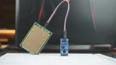
Let’s make a pollution badge, sensing and measuring the pollution in the neighbouring area and displaying it on the Maker Board.
1. Pollution Badge
• In today’s world, we encounter different scenarios where we see different gases being emitted in the atmosphere through vehicles, burning of waste materials, and home appliances like air conditioners and industrial chimneys.
• Monitoring these gases is very important from a safety point of view.
• Gas sensors are very helpful in accomplishing this task, hence we are using MQ135 Gas Sensor.
• This pollution badge will enable us to know when the air quality is bad.
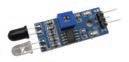
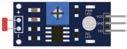
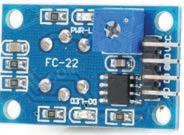
2. MQ135 Gas Sensor
• The gas sensor module consists of a steel exoskeleton under which a sensing element is housed. This sensing element is subjected to current through connecting leads.
• This current is known as heating current. Through it, the gases coming close to the sensing element get ionised and are absorbed by the sensing element.
• This changes the resistance of the sensing element which alters the value of the current going out of it.
Some real-life examples are:


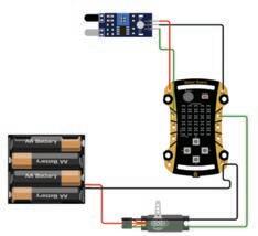
• Connect the A0 of the MQ135 sensor to the A0 of the Maker Board.
• Connect the Vcc of the MQ135 sensor to the Vcc of the Maker Board.
• Connect the Gnd of the MQ135 sensor to the Gnd of the Maker Board.
1. Click on the Control category from the Blocks panel.
2. Drag and drop the My Program block to begin your program. The execution of all the blocks present inside this occurs step by step.
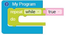
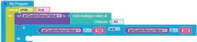
3. Drag the repeat while block from the Loops category and set its value to true. The blocks present inside this will be executed sequentially again and again till the condition is true. As soon as the condition becomes false, the working of blocks inside this loop will stop.
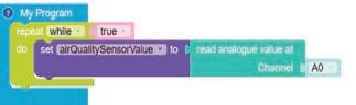
4. Create a variable named "airQualitySensorValue". Drag the set to block from the Variables category and drop it inside the repeat while true block. Attach the read analogue value at Channel block from the Hardware category to the set to block. Set its value to A0 pin status.
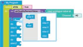
5. Drag the if block from the Control category and drop it below the set to block. Add the else if and else conditions to the if block (refer to the image below).
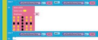
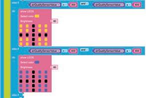
6. Now, define the condition for the if block. If the value of the variable is between 100 and 300, then blocks under this if will be executed.
7. Display a pattern using an LED light of green colour from the Display category that will indicate that pollution is in a Safe range. To change the colour of squares in the LED, select the colour "green" and click on each square. Set the brightness to 60. The LED will look like the figure below.
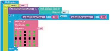
8. Define the condition for the first else if block. If the value of the variable is between 300 and 600, then blocks under this else if will be executed.
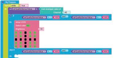
9. Next, display a yellow LED light pattern that will indicate that pollution is in the Unsafe range.
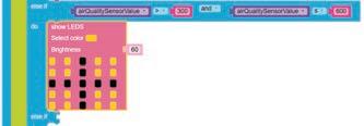
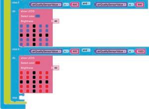
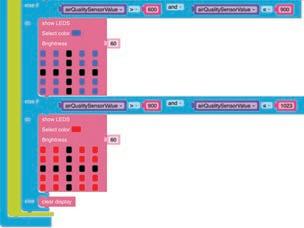
10. Now, define the condition for the second else if block. If the value of the variable is between 600 and 900, then blocks under this else if will be executed.
11. Next, display a blue LED light pattern that will indicate that pollution is in the Dangerous range.
12. Now, define the condition for the third else if block. If the value of the variable is between 900 and 1023, then blocks under this else if will be executed.
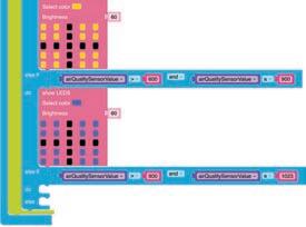
13. Display a pattern using red LED light that will indicate that pollution is in the Hazardous range.
14. Define else as clear display.
15. Give a name to your program, save it, and then compile it.
16. Now the program is ready to burn on the Maker Board, and you can use your pollution badge.
Note: The Maker Board should be connected to your computer through a USB for the experiment to run. Scan QR code to view output
A. Tick () the Correct Option.
1 What does the pollution badge do?
a Displays light patterns
c Monitors heating current
b Detects air quality
d Controls LEDs
2 Which sensor is used in the pollution badge to detect gases?
a Temperature Sensor
c Light Sensor
b MQ135 Gas Sensor
d Ultrasonic Sensor
3 What does the red LED light pattern represent in the pollution badge?
a Safe air quality
c Dangerous air quality
B. Answer the Following.
b Unsafe air quality
d Hazardous air quality
1 Explain how the MQ135 Gas Sensor works to detect air quality.
2 What are the four air quality levels displayed by the pollution badge, and how are they represented using LEDs?
C. Apply Your Learning.
1 Modify the program to display a custom LED pattern when the air quality value is below 100 (very safe range).
2 Suggest one more real-life application for the MQ135 Gas Sensor.
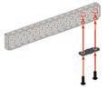
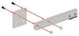
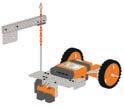
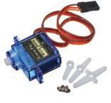
Let us make a circuit to learn how servo motors can be used to build an automatic boom barrier.
The servo motor is a special type of motor with a shaft that can move to a specific position and at a specific speed based on the received input.
The servo motor has three main parts: a motor, a sensor, and a controller.
• The motor provides the mechanical power to move or rotate the shaft.
• The sensors measure the position and the speed of the shaft.
• The controller works like the brain of the servo motor. It tells the motor how much to move and in which direction.
An automatic boom barrier is a gate-like device used to control vehicle entry in restricted areas, such as car parks, toll booths, or private roads.

• Connect the P0 of the Maker Board to the OUT pin of the IR sensor.
• Connect the GND of the Maker Board to the GND pin of the IR sensor.
• Connect the VCC of the Maker Board to the VCC pin of the IR sensor.
• Connect the GND of the Maker Board to the GND pin of the Servo motor.
• Connect the GND of the Maker Board to the -ve pin of the battery.
• Connect the +ve pin of the battery to the +ve pin of the servo motor.
• Connect the PWM pin of the servo motor to the P1 of the Maker Board.
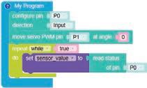
1. Click on the Control category from the Blocks panel.
2. Drag the My Program block to the workspace to begin your program. The execution of all the blocks present inside this occurs step by step.
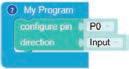
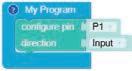
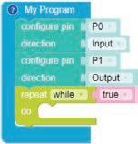
3. Now, drag the configure pin block from the Hardware category and drop it inside the My Program block. Select the P0 pin as Input from the drop-down menu of the block.
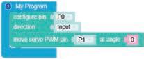
4. Now, drag and drop the move servo PWM pin block from the Hardware category. Select the ‘P1’ pin from the drop-down menu and type ‘0’ in the text box for the angle of the move servo PWM pin block.
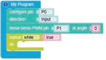
5. Drag the repeat while block from the Loops category and drop it below the move servo PWM pin block. By default, the loop value is set to true.
6. Click on the Variables category.
7. Click on the Create variable button. A pop-up box appears asking you to enter a new variable name.
• Enter a suitable variable name, let us say "sensor_value".
• Click on the OK button.
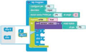
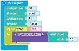
8. Drag the set to block from the Variables category and drop it inside the repeat while block.
9. Drag the read status block from the Hardware category and attach it to the set to block.
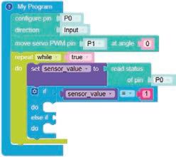
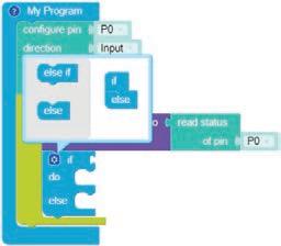
10. Drag the if block from the Control category and place it below the set to block.
11. Click on the settings icon of the if block. A pop-up box appears.
12. Drag the else if block and place it below the if block in the pop-up box (refer to the image below).
13. Again, click on the settings icon to hide the pop-up box.
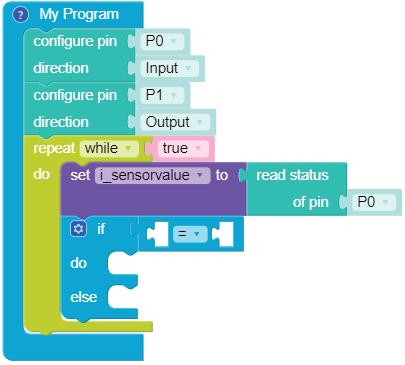
14. Drag the equal operator block from the Control category and attach it to the if block.
15. Drag the sensor_value block from the Variables category and drop it to the left part of the equal operator block.
16. Drag the number block from the Math category and drop it to the right part of the equal operator block. Type ‘1’ in place of ‘0’ in the text box of the number block.
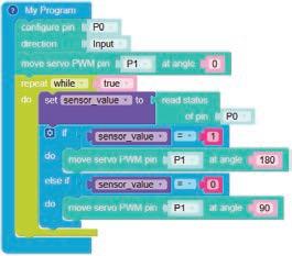
17. Drag and drop the move servo PWM pin block from the Hardware category. Select the ‘P1’ pin from the drop-down menu and type ‘180’ in the text box for the angle of the move servo PWM pin block.
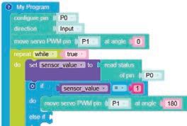
18. Similarly, set another condition for the sensor value. Drag the equal operator block and attach it to the else if block.
19. Drag the sensor_value block and drop it to the left part of the equal operator block.
20. Drag the number block and drop it to the right part of the equal operator block. The number block is set to ‘0’, by default.
21. Drag and drop the move servo PWM pin block in the do part of the else if block. Select the ‘P1’ pin from the drop-down menu of the block. The block is set to angle ‘90’, by default.
22. Give a name to your program, save it, and then compile it.
23. Now the program is ready to burn on the Maker Board.
Note: The Maker Board should be connected to your computer through a USB for the experiment to run.
Scan QR code to view output
A. Tick () the Correct Option.
1 Where are automatic boom barriers commonly used?
a Car parks b Toll booths
c Private roads d All of these
2 Which component of a servo motor determines how much the motor should move and in which direction?
a Motor b Sensor
c Controller d Shaft
3 In the configuration process, which pin is selected as Input from the drop-down menu of the "Configure Pin" block? a P1 b P0
c P2
B. Answer the Following.
1 What is a servo motor?
2 What happens when the sensor value becomes ‘1’?
C. Apply Your Learning.
1 How does an automatic boom barrier enhance security and convenience at entry points?
2 What is the purpose of using automatic boom barriers at toll booths?
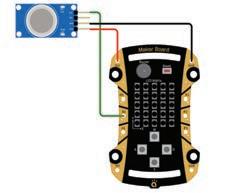
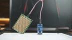
Let’s do an experiment using a sound sensor and LEDs to show colours based on the sound level.
A sound sensor is used to detect noise in the environment and when the noise crosses a certain threshold the sensor sends a signal to the Maker Board which then triggers the LED lights and the buzzer to make a noise. The sensitivity of the sensor can be adjusted using a small screen on the blue hub on the sensor.
Real-life examples include:


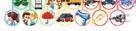
• Connect the P0 pin of the Maker Board to the longer leg of the LED 1 with a resistor in between.
• Connect the GND pin of the Maker Board to the shorter leg of the LED 1.
• After connecting the positive leg of the LED to P0 and the negative leg of the LED 1 to GND, you will see the LED 1 flashing.
• Connect the P2 pin of the Maker Board to the longer leg of the LED 2 with a resistor in between.
• Connect the GND pin of the Maker Board to the shorter leg of the LED 2.
• You will see the LED 2 flashing.
• Connect the G of the Sound Sensor to the Gnd of the Maker Board.
• Connect the + of the Sound Sensor to the Vcc of the Maker Board.
• Connect the DO of the Sound Sensor to the P1 of the Maker Board.
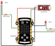
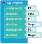
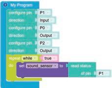
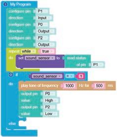
1. Click on the Control category from the Blocks panel.
2. Drag the My Program block to the workspace to begin your program. The execution of all the blocks present inside will occur step by step.

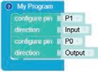
3. Drag the configure pin block from the Hardware category and drop it inside the My Program block. 4. Select the P1 pin as Input. 5. Drag the configure pin block from the Hardware category and drop it below the previous configure pin block.
Select the P0 pin as Output
7. Again, drag the configure pin block from the Hardware category and drop it below the previous configure pin block.
8. Select the P2 pin as Output
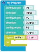
9. Now, drag the repeat while block from the Loops category and drop it below the last configure pin block.
10. Click on the Variables category.
11. Click on the Create Variable button. A pop-up box appears.
a. Enter a suitable variable name like "sound_sensor" in the new variable.
b. Click on the OK button. This will create a variable to store the data of the sound sensor value received from the sensor.
12. Drag and drop the set to block from the Variables category and place it inside the repeat while block.
13. Then, drag the read status of pin block from the Hardware category and place it next to the set to block.
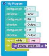
14. Set the value of the read status of pin block to P1.
15. Drag the if block from the Control category and place it below the set to block.
16. Click on the settings icon of the if block. A pop-up box appears.
17. Drag the else block and place it below the if block in the pop-up box (refer to the image below).
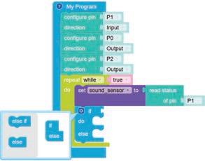
18. Click on the settings icon again to hide the pop-up box.
19. Drag the equal operator block from the Control category and attach it to the if block.
20. Drag the sound_sensor block from the Variables category and drop it in the left value box of the equal operator block.
21. Drag the number block from the Math category and drop it inside the right value box.
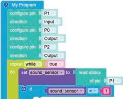
22. Type "1’’ in place of 0. If the value of the sound_sensor variable is equal to 1, i.e., the sound sensor senses the sound, the blocks under the if block will be executed, otherwise the blocks under the else block will be executed.
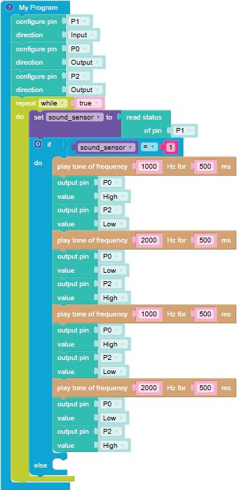
23. Drag the play tone of frequency block from the Sound category and drop it inside the do part of the if block.
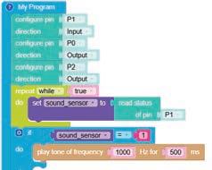
24. Set the frequency as 1000 Hz for 500 ms.
25. Drag two output pin value blocks from the Hardware category.
26. For the first block, select the P0 pin as "High".
27. For the second block, select the P2 pin as "Low".
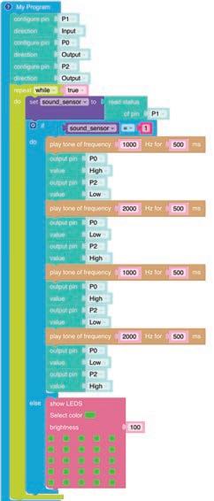
28. Similarly, set the conditions for the different frequency and pin values as shown in the figure below.
29. Now, drag the show LEDS block from the Display category and drop it inside the else condition.
30. Assign any colour and pattern in the LED Matrix. Set the brightness to 100.
31. Give your program a name, save it, and then compile it.
32. Now, the program is ready to burn on the Maker Board.
Note: The Maker Board should be connected to your computer through a USB for the experiment to run.
Scan QR code to view output
A. Tick () the Correct Option.
1 Which pin is configured as an input to receive data from the sound sensor?
a P0
c P2
b P1
d P3
2 What variable name is created to store the sound sensor data?
a sensor_level
c sound_sensor
3 Why is the read status of pin block set to P1 in this program?
a To turn on the LED
b sound_level
d noise_level
b To detect input from the sound sensor
c To set up the alarm frequency d To show an LED pattern
B. Answer the Following.
1 Why is it important to have both the if and else conditions in this program?
2 What happens when the sound sensor detects sound in this experiment?
C. Apply Your Learning.
1 Give a real-life example where a burglar alarm is used.
2 If you wanted to use this system in a library where sound levels should stay low, how would you adjust the frequency of the alarm tone and the LED brightness to ensure it does not disturb people but still alerts the staff?
• A sensor is a device that detects and responds to certain inputs from the physical environment. These inputs can include light, heat, motion, moisture, pressure, and other environmental factors.
• A water sensor brick is designed for detecting water. It can be used in various applications, such as sensing rainfall, monitoring water level, and detecting liquid leakage.
• This type of sensors can detect the presence, level, volume, or absence of water.
• The servo motor is a special type of motor with a shaft that can move to a specific position and at a specific speed based on the received input.
• The servo motor has three main parts: a motor, a sensor, and a controller.
• The motor provides the mechanical power to move or rotate the shaft.
• The sensors measure the position and the speed of the shaft.
• The controller works like the brain of the servo motor. It tells the motor how much to move and in which direction.
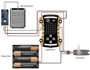
Let us make a project that uses a rain drop sensor to develop a smart window using servo motor to understand the concept of water sensors. Some of the real-life examples are:


• Connect the jumper cable wires to the water sensor.
• Connect the VCC of the water sensor and the red wire of the servo motor to the VCC of the Maker Board.
• Connect the GND of the water sensor and the brown wire of the servo motor to the GND of the Maker Board.
• Connect the orange wire of the servo motor to the P1 of the Maker Board.
• Connect the D0 of the water sensor to the P0 of the Maker Board.
• Connect the battery connector and the battery, and keep ready.
• Connect the positive terminal to the Vin.
• Connect the negative terminal to the Gnd.
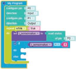
1. Click on the Control category from the Blocks panel.
2. Drag the My Program block to the workspace to begin your program. The execution of all the blocks present inside this occurs step by step.
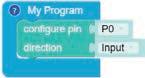
3. Drag the configure pin block from the Hardware category and drop it inside the My Program block.
4. Set the P0 pin as Input
5. Again, drag the configure pin block from the Hardware category and drop it inside the My Program block.
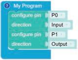
7. Drag the repeat while block from the Loops category and drop it below the configure pin block. This block is set to true, by default.
8. Click on the Variables category, and then click on the Create variable button. A pop-up box appears. Enter a suitable variable name, such as "i_sensorvalue". Click on the OK button.
9. Now, drag the set to block inside the repeat block and drag the read status block from the Hardware category and drop it as shown in the figure below.
10. Drag the if block from the Control category and drop it below the repeat block.
11. Click on the settings icon of the if block. A pop-up box appears.
12. Drag the else condition to the pop-up box, and drop it below the if block. The else condition is executed when the condition is false.
13. Again, click on the settings icon to hide the pop-up box.
14. Drag the equal operator block from the Control category and attach it to the right of the if block.
15. Now, insert the "i_sensorvalue" variable block in the left part of the equal operator block.
16. Drag the number block from the Math category and drop it to the right part of the equal operator block.
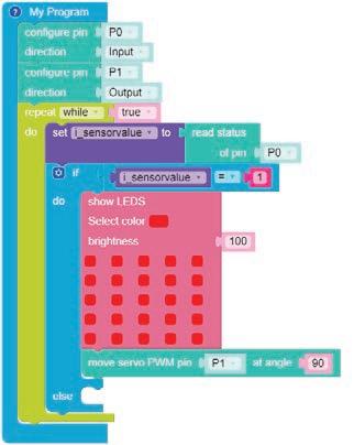
17. Now, drag the show LEDS block from the Display category and drop it inside the if condition.
18. Assign any colour or pattern to the LED Matrix.
19. Now, drag and drop the move servo PWM pin block from the Hardware category. The code will look like this.
20. Again, drag the show LEDS block from the Display category and drop it inside the else condition.
21. Assign any colour and pattern to the LED Matrix.
22. Drag and drop the move servo PWM pin block from the Hardware category. The code will look like this.
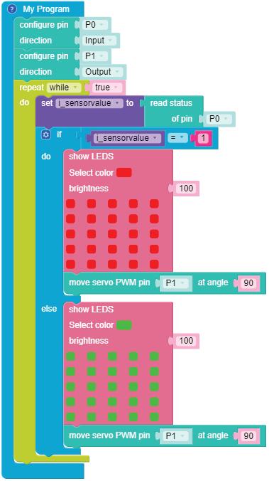
23. Give a name to your program, save it, and then compile it.
24. Now, the program is ready to burn on the Maker Board.
Note: The Maker Board should be connected to your computer through a USB for the experiment to run.
Scan QR code to view output
A. Tick () the Correct Option.
1 What is the main function of a water sensor?
a Measure temperature b Detect the presence of water
c Control servo motor speed
2 What is the role of the servo motor in this project?
a Detect
c Provide powers to the water sensor
3 Which pin is configured as an input for the water sensor?
a P1
c VCC
B. Answer the Following.
1 What are the three main components of a servo motor?
d Monitor light levels
b Provide mechanical power to move the rain shed
b To connect to the Maker Board
b P0
d GND
2 How is the battery connected to the circuit?
C. Apply Your Learning.
1 If you want to add a buzzer that sounds when rain is detected, how would you integrate it into the circuit and program?
2 What troubleshooting steps would you take if the servo motor does not respond when water is detected?
Let us use the Maker Board to do some maths and make a calculator using AI speech recogniser mode. We will perform addition, subtraction, multiplication, and division operations on numbers depending upon user input. We will use a Maker Board to display the numbers.
Artificial Intelligence, or AI, is the field of computer science that deals with the study of the principles, concepts, and technology for building machines that can think, act, and learn like humans. Machines possessing AI should be able to mimic human traits like making decisions, recognising patterns, predicting outcomes based on certain actions, learning, and improving on their own.
NLP is a domain of AI that enables computers to understand human language and generate appropriate responses when we interact with them. It allows computers to talk to us in a way that feels natural to us. Popular examples of NLP applications include Google Assistant, Siri, Alexa, and Google Translate.
Computer Vision is a domain of AI which uses cameras to see and understand visual information.
Some real-life examples of NLP are:
1. Face Recognition in Smartphones 2. Self-Driving Cars
In this experiment, the use of NLP in the Maker Board calculator includes:
• Recognising mathematical commands such as "add" and "subtract".
• Converting spoken commands into actions that the Maker Board can execute.
• Detecting unclear input and prompting the user to repeat commands.
1. Click on the Control category from the Blocks panel.
2. Drag and drop the My Program block to begin your program. The execution of all the blocks present inside this will occur step by step.
3. Create three variables named number1, number2, and result, and set their values to 0 using the Variables category. Drag and drop the set to block for all three variables, as shown in the figure here.

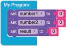
4. Drag and drop the repeat while block from the Loops category.
5. Create a variable named "voice" using the Variables category.
6. Drag and drop the set to block, "select voice" from the drop-down list, and attach the get recognised speech block from the Speech Recognition category.
7. Now, drag the if block from the Control category and drop it below the set to block.
8. Click on the settings icon of the if block. A pop-up appears.
9. Drag the else if block and drop it below the if block in the pop-up box. Repeat this three times.
10. Again, click on the settings icon to hide the pop-up box.
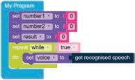
11. Create a function named "generate num1". To create a function, click on the Functions category and drag the to block. Replace the do something with the desired function name. The function will be created.
Note: Functions are not set within the code. They are placed separately in the workspace. You can reuse it by calling up the function name in your code.
12. Increase the value of the number1 variable by 1 to get the desired number using the Variables category.
13. Display the value of the number1 variable using the show number block from the Display category and set the colour to green using the colour palette. Set the Brightness to "100".
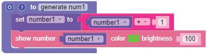
14. Now, drag the includes block from the Text category.
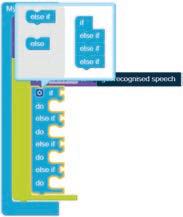
15. Drag the Voice block from the Variables category and drop it inside the String1
16. Rename the String2 block as "One" and call the function "generate num1".
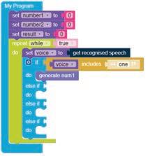
Note: You can create a new function from an existing one by right-clicking and selecting "duplicate". Then you can change the function name and other values in the value box as per your requirements.
17. Similarly, create a function named "generate num2" and increase the value of the number2 variable value by 1 to get the desired number and then display it.
18. Drag the includes block from the Text category and drop it inside the first else if block.
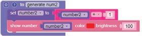
19. Drag the Voice block from the Variables category and drop it inside the String1.
20. Rename the String2 block as "two" and call the function "generate num2".
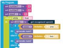
21. Create a function named "addition" and set the value of the variable result to the addition of number1 and number2 and show the result as reflected in the figure below.
22. Drag the includes block from the Text category and drop it inside the second else if block.
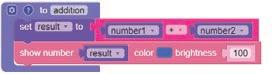
23. Drag the Voice block from the Variables category and drop it inside String1.
24. Rename the String2 block as "add" and call the function "addition".
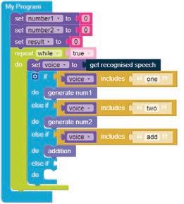
25. Create a function named "Subtraction" and set the value of the result to subtraction of number1 and number2 based on which number is greater. Show the result on the matrix using the if and else blocks. If the conditional statement of the if block is false, then the statement(s) of the else block will be executed.
26. You can get the else block by clicking on the settings icon of the if block.
27. A pop-up box appears. Drag the else block and drop it below the if block in the pop-up box.
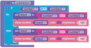
28. Drag the includes block from the Text category and drop it inside third else if block.
29. Drag the Voice block from the Variables category and drop it inside String1
30. Rename the String2 block as "subtract" and call the function "subtraction".
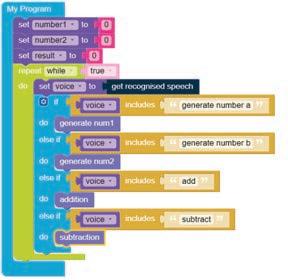
31. Name your program, save it, and then compile it.
32. Now the program is ready to burn on the Maker Board.
Note: The Maker Board should be connected to your computer through Bluetooth or a USB cable for the experiment to run.
33. Click on the Run button in the AI window.
34. Allow the system to use your microphone to hear your commands.
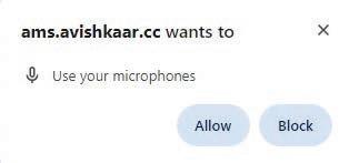
35. Click on the microphone button in the AI window.
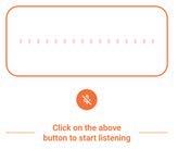
36. Give any command (one, two, add, or subtract).
37. Click the microphone button again and observe the output on the Maker Board.
In this experiment, computer vision is used to recognise hand gestures through the Maker Board’s camera.
• The AI model is trained to detect specific hand poses, such as "Palm," "Fist," "ThumbsUp," and "Peace."
• Once trained, the model can identify these gestures in real-time.
• Each gesture then triggers specific actions within the game, such as generating num1, num 2, addition, and subtraction.
• This allows players to control the sprite with their hand movements.
Instructions
Before we start writing the code, let us train our AI Model. Follow the given steps:
1. Allow the system to use your camera.
2. Click on the Configure AI Model in the AI Window.
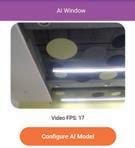
3. Create your model by selecting Handpose.

4. Add a name for your model and save it. You can also skip it.
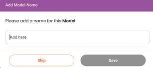
5. Now, add the label name as 'Palm' and save it.
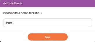
6. Click on the "Start Recording" button and show your palm up to 60 Frames
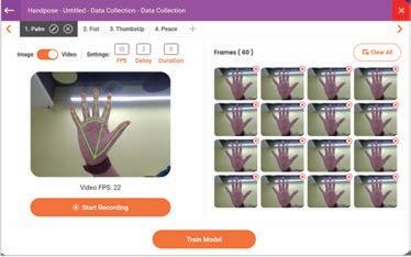
7. Now, click on the Plus sign on the top left corner and add another label, 'Fist'. 8. Similarly, add other labels such as 'ThumbsUp' and 'Peace'.
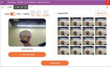

9. Now, click on Train Model button to train the AI on these hand poses. It will take a few minutes.

10. Add an appropriate model name and save it.
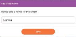

11. Test your model to check whether the gestures are working correctly, then download it.
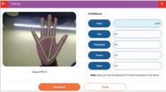
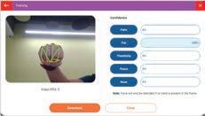
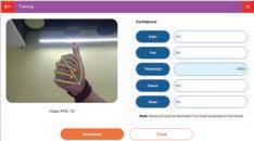
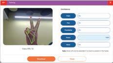
12. You are now ready to write your code.
1. Click on the Control category from the Blocks panel.
2. Drag and drop the My Program block to begin your program. The execution of all the blocks present inside this will occur step by step.

3. Create three variables named number1, number2, and result, and set their values to 0 using the Variables category. Drag and drop the set to block for all three variables, as shown in the figure here.
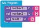
4. Drag and drop the repeat while block from the Loops category.
5. Now, drag the if block from the Control category and drop it inside the repeat block.
6. Click on the settings icon of the if block. A pop-up appears.
7. Drag the else if block and drop it below the if block in the pop-up box. Repeat this three times.
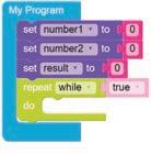
8. Click on the settings icon again to hide the pop-up box.
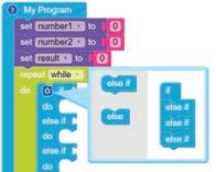
9. Drag the equal operator block from the Control category and attach it to the right of the if block.
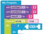
10. Now, drag the get detected AI label block from the AI category and drop it to the left part of the equal operator block.
11. Drag and drop the Palm block to the right part of the equal operator block.
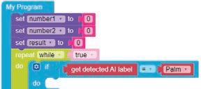
12. Create a function named "generate num1". To create a function, click on the Functions category and drag the to block. Replace the do something with the "generate num1" name. The function will be created.
Note: Functions are not set within the code. They are placed separately in the workspace. You can reuse them by calling up the function name in your code.
13. Drag the set to block and increase the value of the number1 variable by 1 to get the desired number using the Variables category.
14. Display the value of the number1 variable using the show number block from the Display category and set the colour to green from the colour palette and set the Brightness to "100".

15. Now, call the function "generate num1" and drop it inside the do block.
16. Drag and drop the Time block from the Control category and set it below the function "generate num1" as shown in the figure here.
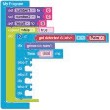
Note: You can create a new function from an existing one by right-clicking and selecting "duplicate". Then you can change the function name and other values in the value box as per your requirements.
17. Similarly, create a function named "generate num2" and increase the value of the number2 variable value by 1 to get the desired number and then display it.
18. Drag the equal operator block from the Control category and attach it to the right of the if block.
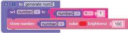
19. Now, drag the get detected AI label block from the AI category and drop it to the left of the equal operator block.
20. Drag and drop the Fist block to the right of the equal operator block.
21. Now, call the function "generate num2" and drop it inside the do block.
22. Drag and drop the Time block from the Control category and set it below the function "generate num1" as shown in the figure below.
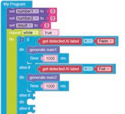
23. Create a function named "addition" and set the value of the variable result to the addition of number1 and number2 and show the result as shown in the figure here.
24. Drag the equal operator block from the Control category and attach it to the right of the if block.
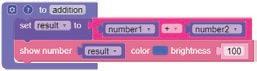
25. Now, drag the get detected AI label block from the AI category and drop it to the left part of the equal operator block.
26. Drag and drop the ThumbsUp block to the right part of the equal operator block.
27. Now, call the function "addition" and drop it inside the do block.
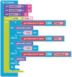
28. Create a function named "Subtraction" and set the value of the result to subtraction of number1 and number2 based on which number is greater. Show the result on the matrix using the if and else blocks.
29. If the conditional statement of the if block is false, then the statement(s) of the else block will be executed.
30. You can get the else block by clicking on the settings icon of the if block.
31. A pop-up box appears. Drag the else block and drop it below the if block in the pop-up box.
32. Drag the equal operator block from the Control category and attach it to the right of the if block.
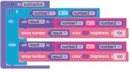
33. Now, drag the get detected AI label block from the AI category and drop it to the left of the equal operator block.
34. Drag and drop the Peace block to the right of the equal operator block.
35. Now, call the function "subtraction" and drop it inside the do block.
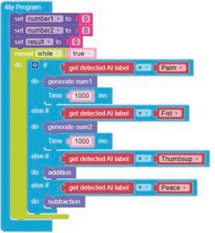
36. Give your program a name, save it, and then compile it.
37. Now the program is ready to burn on the Maker Board.
Note: The Maker Board should be connected to your computer through Bluetooth or a USB cable for the experiment to run.
38. Observe the output on the Maker Board. Scan QR code to view output
A. Tick () the Correct Option.
1 What gesture is used to generate num1 in this program?
a Fist b Palm
c Peace d ThumbsUp
2 What command is used to recognise the speech input in this code?
a detect speech
c recognise command
b get recognised speech
d voice command
3 What is the purpose of the "addition" function in this program?
a To generate number1
c To add number1 and number2
B. Answer the Following.
b To generate number2
d To display results
1 What is computer vision, and how is it applied in this project?
2 Why is it important to set the initial values of number1, number2, and the result to 0?
C. Apply Your Learning.
1 How would you modify the code to handle cases where users might say "plus" instead of "add"?
2 What steps would you take to create a function that shows the result of multiplying two numbers?
This book introduces learners to the captivating realm of robotics, with a learner-friendly, motivating, and hands-on approach. It combines theoretical understanding with practice, through insightful examples of real-world applications, while promoting creativity and coding skills. Emphasising a project-based learning methodology, the book provides a series of projects, each with detailed instructions. These instructions can be effortlessly executed using the accompanying robotics hardware kit. The assembly and programming of the robotics systems are done through block-based coding, and simulation environments; accelerating the experiential learning journey of the learners.
• Hands-on Experiments: Engaging experiments that allow students to build and test-run robots themselves.
• Detailed Coding Practice: Step-by-step coding instructions to program robots, making it easy for beginners to learn.
• Things Around Us: Each experiment connects robotics to real-world scenarios, showing how technology solves everyday problems.
• Comprehensive Background: Clear explanations of the concepts and the technology behind each experiment, helping students understand the "why" and the "how."
• Interactive Exercises: Exercises at the end of each experiment to reinforce learning and to challenge students to think critically.
Uolo partners with K-12 schools to provide technology-enabled learning programs. We believe that pedagogy and technology must come together to deliver scalable learning experiences that generate measurable outcomes. Uolo is trusted by over 15,000+ schools across India, Southeast Asia, and the Middle East.