THE PEAK DISTRICT TERTIARY ASSEMBLY -

UNIT Y4 TB
TOM BIRDYEAR 4 @unit14_ucl
All work produced by Unit 14
-
www.bartlett.ucl.ac.uk/architecture
Copyright 2021
The Bartlett School of Architecture, UCL All rights reserved.

No part of this publication may be reproduced or transmitted in any form or by any means, electronic or mechanical, including photocopy, recording or any information storage and retrieval system without permission in writing from the publisher.

@unit14_ucl
 Cover design by Charlie Harris
TOM BIRD YEAR 4
tombird2000@hotmail.com
@tbird.tbird
THE PEAK DISTRICT TERTIARY ASSEMBLY
A RURAL TERTIARY WORKING HUB
As the UK’s economy shifts further towards the tertiary and quaternary sectors, the economic utility of the physical landscapes is in decline. The fastest growing economic sector is the export of knowledge and services, projected to overtake domestic demand by 2070. As business moves overseas, cities no longer hold the inherent advantage of providing a close proximity between businesses and their clients, opening up new potential for the decentralisation of the tertiary export sector beyond cities.
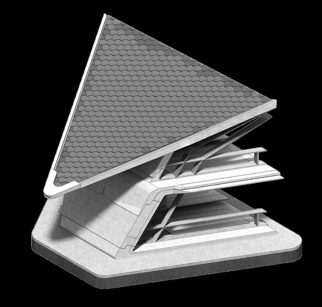
It is rural economies that bear the brunt of the landscapes’ declining utility. Often forced to allow low-quality development of their natural landscapes to stimulate economic growth. Areas of outstanding natural beauty, often lying just outside the abstract boundaries of conservation areas and are contaminated by sprawling residential developments.
In an act of conservation, to detach the reliance of the rural economies from the development of its landscape, this project proposes a tertiary working assembly on the eastern border of The Peak District National Park. Offering businesses high-quality workspaces to cultivate a decentralised working lifestyle centred around a connection to the picturesque rural landscape.
Y4 TB
THE PEAK DISTRICT NATIONAL PARK, ENGLAND, U.K.
Contents:
001-012 Section 1 - Brief Development
013-017 Section 2 - Design & Systems Development:
018-025 Section 3 - Detailed Design:
026-033 Section 4 - Final Drawings:
034-037 Appendix - Additional Technical Information:
Research: - 001 The Extractive Rural Economy - 002 The Rural Picturesque - 003 Rural Tertiary Sector Potential - 004 Programme - 005 Site - 006 Site - 007 Growing Infrastructure - 008 Material Research - 009 Material Research - 010 Material Research - 011 Material Handling & Production - 012 Standardised, Pre-cast Logic
&
- 013 Connection to The Landscape - 014 Global Arrangement - 015 Typical Workspace Design - 016 Monolithic Structural Language - 017 Design Genesis
- 018 Structural Brief - 019 Pre-Cast Infralightweight Concrete - 020 Pre-cast Standardisation - 021 Component Transportation - 033 Component assembly - 022 Structural Strategy - 023 Material Usage - 024 Component Assembly - 025 Construction Sequence
- 026 Lower Ground Floor Plan - 026 Ground Floor Plan - 027 First Floor plan - 028 Aerial Perspective - 029 Perspective Section c-c - 030 Perspective Section b-b - 031 Evening Perspective View - 032 Section a-a - 033 Autonomous Link Dock
- 034 Component Composition - 035 Thermal Performance - 036 Heating & Cooling Strategy - 037 Global Ventilation & Fire Strategy 2023 PG14 Advanced Architectural Design
Section 1
Brief Development & Research
Pages: 001-012
The Extractive Rural Economy An Increasing Threat to Conservation
The challenge of conservation:
Extractive economic practices in rural England, which rely on using and altering the physical landscape to generate revenue are historically dominant. These practices include agriculture, quarrying, secondary processing, and sprawling development. However, this economic model is reliant on continual change of the physical landscape and often comes at the expense of environmental conservation. As socioeconomic priorities shift, the most damaging practices, such as quarrying and development, are becoming more prevalent, while sustainable agriculture is in decline. This trend poses a direct threat to the natural beauty and diversity of the English countryside, making conservation efforts increasingly difficult.
Economic Sector Distribution:


Case Study: Matlock - Derbyshire

Location: Peak District:
Eastern edge of The Peak District National Park - Derbyshire.
Receiving only partial protective status due to occupying the conservation boarder.
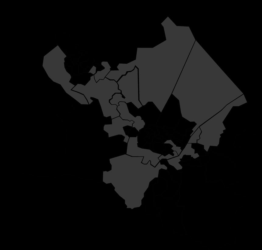
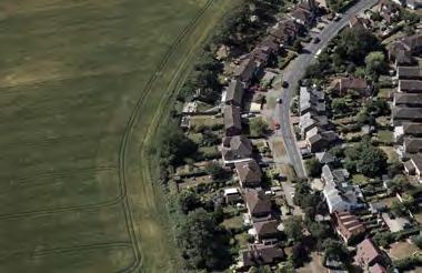
Located on the eastern edge of The Peak District National Park, Matlock offers contemporary case study of the impact of shifting extractive economic practices. Initially a small town surrounded by productive farmland of outstanding natural beauty. Its desirable rural location has seen a large amount of its farmland converted into sprawling housing development as the economic potential of housing overtakes that of farming. The result is a serious alteration the aestetic qualities of its landscape & infrastructure that is unable to cope with its new density. Shown left, highlights areas that have seen an increase in properties of 50% or more in the last 10 years. Expanding the once condensed town into the wider landscape, often with low quality, profit driven housing developments.
2023 Tom Bird Advanced Architectural Design Section 1
Extractive vs Resource Efficient Extractive Sectors 3 Year % change 2% -2% Agriculture Quarrying Secondary Processing Sprawling Development -4% 4% 6% 8% 10% Rural Economy Composition
Regions with < 50% increase in homes: 10% 20% 30% 40% 50% 60% 70% Pre-Industrial % of total UK economy Industrial Post-Industrial UK Economic Sector Change Tertiary Secondary Primary Quaternary Agriculture 35% 12.5% 12.5% 20% Secondary Processing Quarrying Sprawling Development
65%
Wider “resource efficient” Practices
The Rural Picturesque





Prioritising Aestetic Conservation
Removing the economic burden from the landscape:
Proposing the picturesque qualities of the rural landscape as its primary resource in an argument for aesthetic conservation.






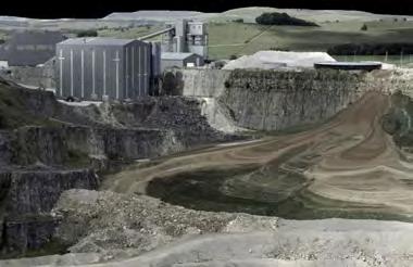
Areas of outstanding natural beauty are afforded a level of protection from development and are impacted less by extractive economic practices. However, quarrying still takes place in many of England’s natural parks and is expanding. Additionally, sprawling development is further encroaching on their borders.
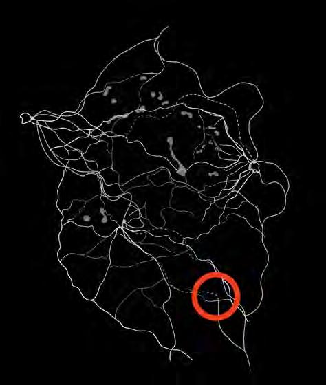
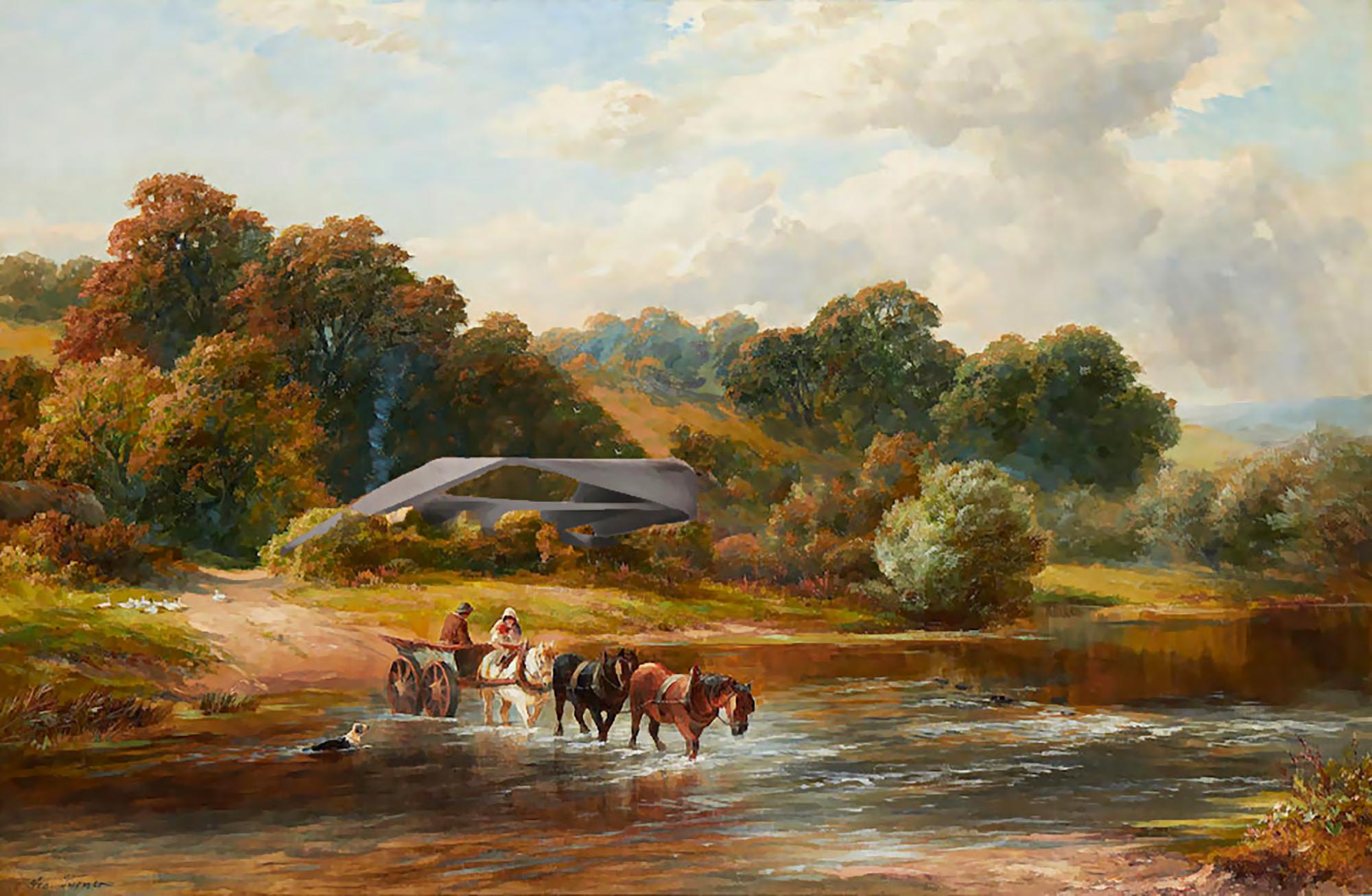
Many rural areas beyond the geographical borders of these parks hold the same aesthetic potential yet are still developed upon. These were extensively catalogued by artist George Turner throughout Derbyshire, both inside and beyond these contemporary boundaries, as shown below.













In an act of rural conservation, the local economic model should be shifted towards one that capitalizes on the landscape’s greatest resource - its aesthetic beauty and the associated health and social benefits that come from occupying them. This may be achieved by following the UK’s economic trajectory, prioritizing the tertiary (service) sector.
2023 Tom Bird Section 1
George Turner works 1870 - 1910:
Sprawling development - Matlock
Advanced Architectural Design
Great Rocks Dale Quarry - Peak District
Rural Tertiary Sector Potential An Argument for Decentralisation
Decentralisation of the tertiary sector:

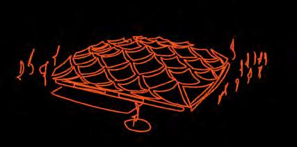


As a whole the UK’s economy become increasingly based in the tertiary sector, providing services predominantly to domestic, but increasingly also international clients. The current ‘domestic focused’ model of the UK’s Tertiary sector benefits from the inherent density of UK cities. As the businesses providing tertiary services are in close proximity to those they serve.
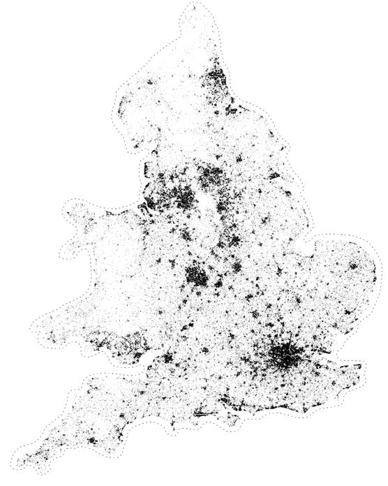
This materialises in condensed clusters of tertiary sector jobs, predominantly based around the UK’s dense urban centres. Leaving rural areas, especially those surrounding national parks with little connection to the tertiary sector.
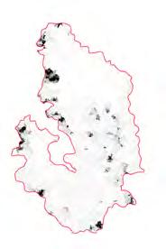
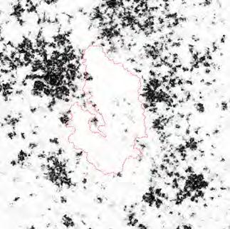
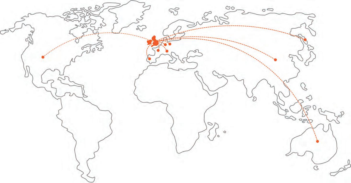
However as shown below, the UK’s tertiary export sector is undergoing rapid growth and is projected to overtake domestic markets by:


The resulting model is shifting towards an export based sector, Therefore the close proximity benefits offered by urban centres are no longer a consideration. And companies who are tertiary export focused may look beyond UK cites for their offices where they are able to develop with more land availability & better working conditions. Creating the opportunity for new exploration of large scale, rural tertiary workplaces.
A new rural tertiary export sector:

The export tertiary sector may be based in the UK’s countryside with no inherent disadvantaged, as clients are projected to be international. Predominantly; USA, Germany, France, Ireland, Netherlands. Thus, nurturing a new type of rural economy - Tertiary export.


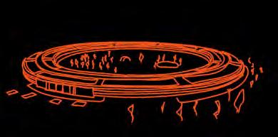
International examples export based businesses adopting this decentralised model have generated architectural response in the form of the Corporate Campus (left). By moving out of dense urban centres buildings are afforded more land & potential to form an meaningful connection to the surrounding landscape, whilst simultaneously providing high quality, industry leading job opportunities to a wider area.
2023 Tom Bird Section 1
Leeds Manchester Liverpool Sheffield London
Tertiary Sector Revenue 2070 = Domestic £1046b £174b 2010 - 2020 Growth Domestic 7% 43% Export Export
Advanced Architectural Design
The Rural Tertiary Hub
An Alternative Working Life-style:
The work undertaken by a person working in the tertiary sector is inherently unnatural. Most likely desk, computer, or laboratory work. The potential to undertake this work whilst maintaining a connection to the natural landscape offers a healthier solution. Placing the tertiary sector within nature with the aim of developing a new working lifestyle around this connection.
Self Sufficiency:
Combating the issues faced by the isolated nature of rural sites through designing for self sufficiency. Taking inspiration from comprehensive self sufficient found in polar exploration architecture & applying this to the tertiary industry context. In order to sustain the programme must find connectivity though virtual & physical means to existing industry. Draw people to it though a unique attribute. & Be unaffected by unreliable rural infrastructure.
Decentralisation:


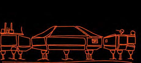
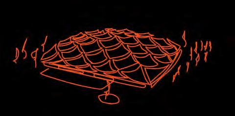

Moving the tertiary sector beyond dense urban centres. Corporation such as Apple & Google have found success in concentrating their operations into the corporate ‘campus’ Moving away from the urban centres offers more land and construction opportunity, ultimately leading to healthier working environment. One with a better connection to the landscape.

Community Programme:
Crafting the programme of the intervention to both draw people in & uplift those already present. Also attributes associated with the tertiary sector to the wider community to share its benefit, such as expertises in emerging industries.


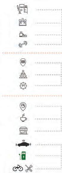
Semi-Public Public Private Dedicated office Subscription Public Resource Infrastructure Resource 45% 20% 15% 20%
Virtual & Physical Connectivity Draw Integrated infrastructure
Programme
2023 Tom Bird Section 1 Advanced Architectural Design
The Peak District National Park - East
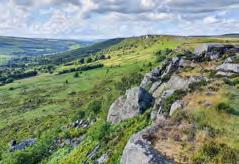
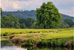
National Park Location:
Site Condition:
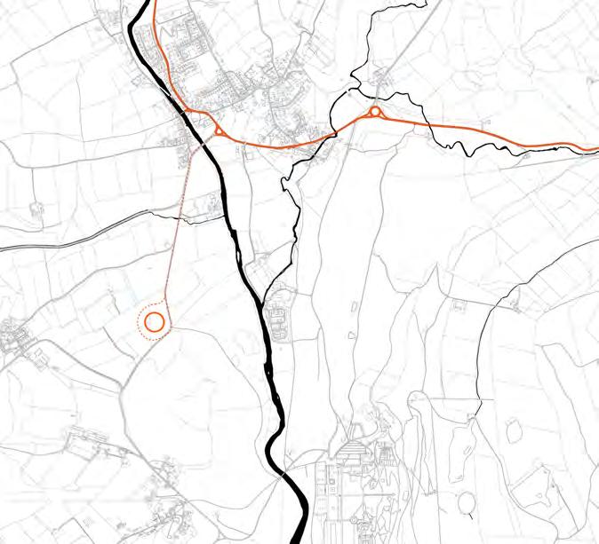
The chosen site is in the heart of the Peak District. A rural site, but well connected, located upon historic industrial transport routes, thus able to benefit from its remaining infrastructure.


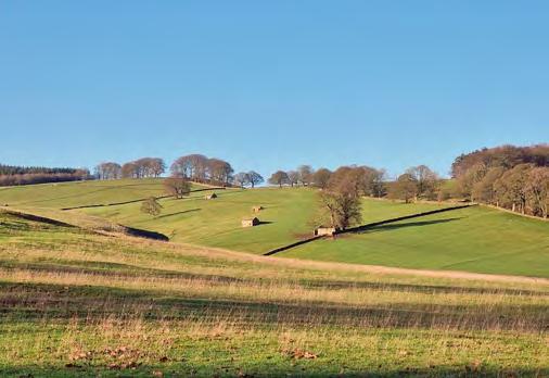
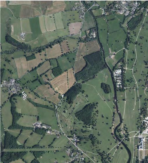
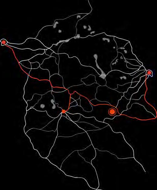
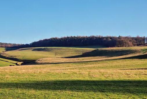
Surrounding Landscape:

2023 Tom Bird Section 1 MANCHESTER SHEFFIELD BUXTON
Automated Transport link Automated Transport link 1. Baslow & The Edges Natural plato 2 Old Farm Deer Migration Zone Site 3 5 4 6 1 2 3. Downs 4. River Walk 5 Edensor Village 6. Chatsworth Estate Site
Advanced Architectural Design
Prevailing Weather:
Overall, the Peak District receives a comparatively large amount of rainfall & high strength winds compared to the rest of the UK. However, the sloped topography of the site alleviates flooding concerns due to rainfall, but does increase its exposure to prevailing winds.
Flood Risk:
The River Derwent lies close to the site. Flowing from the highest points of the peaks down into the southern basins.
River levels are regulated by Derwent reservoir & flooding is infrequent. Due to being located in a small valley, passing by the site flash flood risks only effect the immediate banks of the river.
Deer & Livestock Migration:
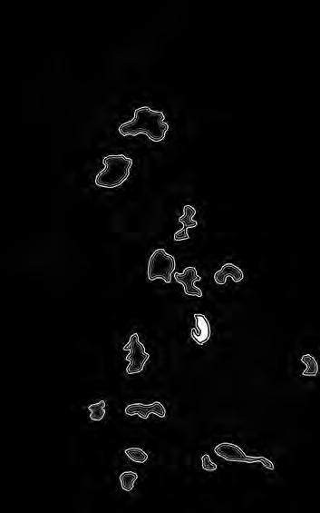
Chatsworth Estates dedicates much of the surrounding land under its ownership as a semi controlled Deer reservation & lambing grounds. Shown are its boundaries and seasonal direction of migration. Vehicle travel is regulated to prevent danger to wildlife.
Lambing Season: April 30th - August 1st
Deer Migration: December 1st - April 30th
Topography:
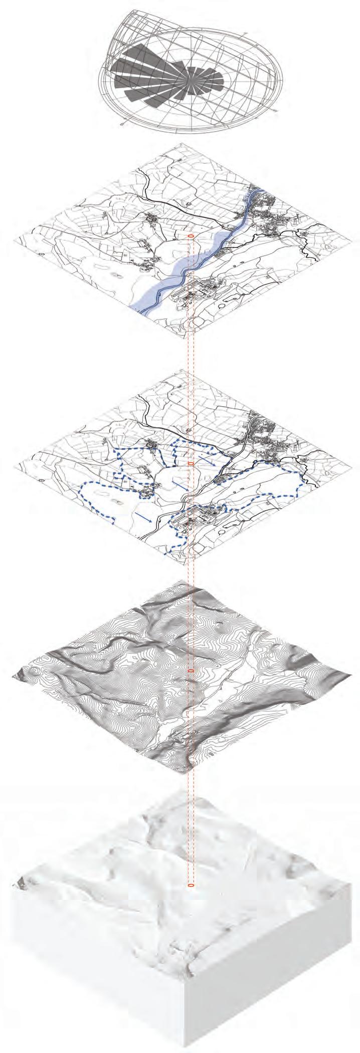
The picturesque qualities of the Peak Districts landscapes are orchestrated by its unique topography. Rolling hills & sharp rock edges form the landscape vernacular.
Geology:
The geological make-up is dominated by layer of shale & limestone. Physical resources that have been quarried & proceed fuelling its early industrial economy & development. Exposed rocky ground is also frequently found due to shallow earth in much of landscape. Causing poor quality farmland.
2023 Tom Bird Section 1
Advanced Architectural Design
Site Environmental Context
Growing Infrastructure
Strengthening Existing Connections
Utilising post industrial infrastructure:

The Peak District contains an extensive network of ex-industrial road & rail networks that connect it to the surrounding cites of Manchester, Sheffield, & Buxton. Originally used to transport material from its quarries for trading. These connections may be utilised to form a commuter network.. Connecting the new tertiary sector intervention to surrounding cites.
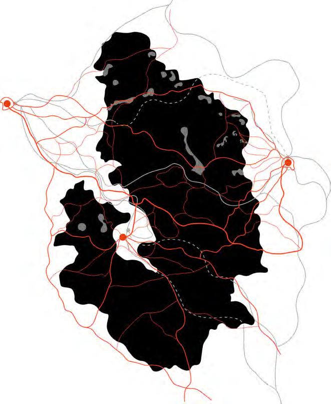
Road Rail Disused Rail
Proposed Route
The Autonomous Link:


A new transport infrastructure connecting Manchester, Sheffield, & Buxton via the Peak District. Implementing a continuous flow of automated traffic. Automation allows extremely efficient traffic flow of autonomous cars. Moving in closely following columns.
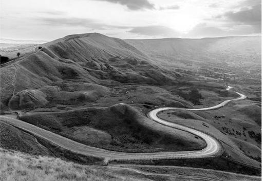
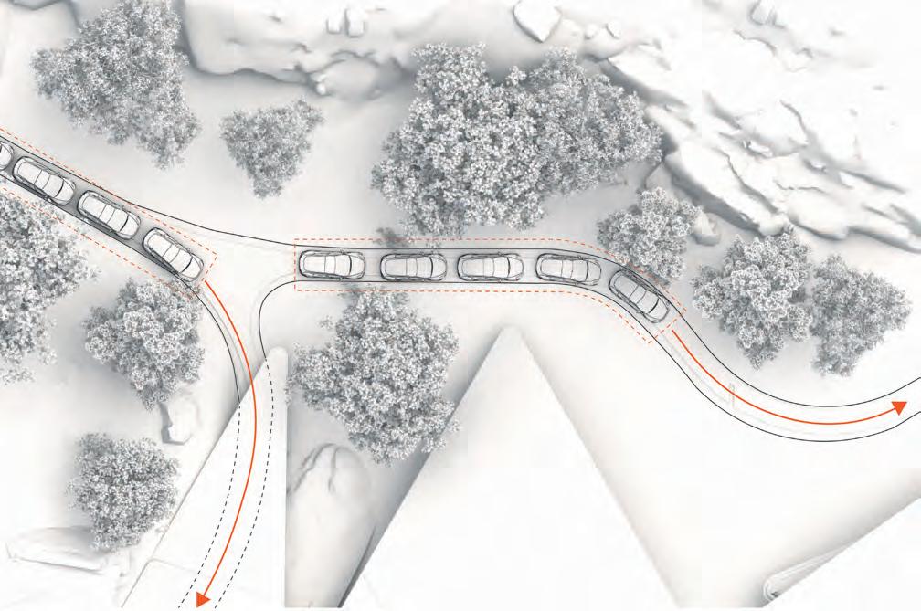
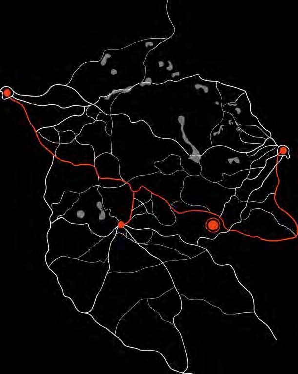
The intervention becomes a rural hub upon this new autonomous link, providing accessibility for commuters with a dedicated drop-off zone. Additionally, offering recharging & maintenance facilities to the operating vehicles.
Autonomous vehicles are well-suited for narrow country roads, where traditional vehicles can be limited in their manoeuvrability. With advanced sensors and real-time decision-making capabilities, autonomous vehicles can navigate challenging road conditions and obstacles with ease, optimizing their speed and distance to reduce the risk of collisions. They can communicate with each other and traffic management systems, coordinate their movements, and avoid congestion.
 MANCHESTER MANCHESTER
SHEFFIELD SHEFFIELD
BUXTON BUXTON
2023 Tom Bird Section 1 Advanced Architectural Design
Material Research
Continuous Surface Folding
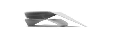


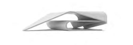


Manipulating the Concrete Plane:
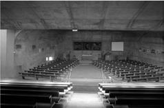
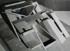
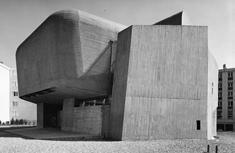
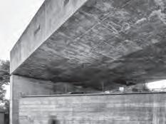
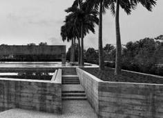
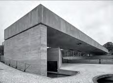
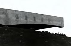
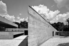
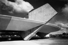
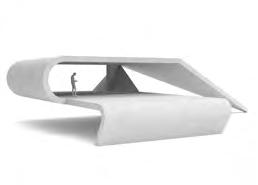
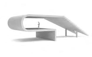
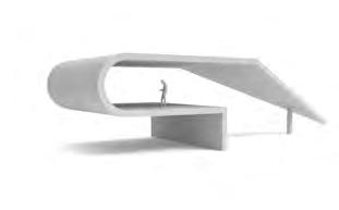
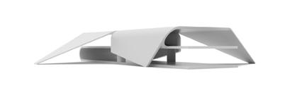

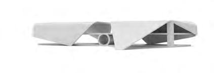
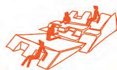
Considering the manipulation of a single, monolithic surface to generate forms that promotes connection & interaction with their surrounding landscape and interactive enclosure at the human level. When combined, aiming to produce a form that is able to interact & integrate with the picturesque landscape it will ultimately sit within, whilst providing multiple opportunities for informal working spaces.
For Interaction with the exterior:
Utilising the expressive opportunity offered by concrete. Manipulating and suspending planes to creates moments of interaction with the exterior through shading, enclosure, and negative space.
For Further Utility:
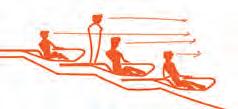
Claud Parent - Function of the Oblique
Increasing the utility of a single plane by creating a sloped surface that promotes interaction at the human scale, whilst also increasing the amount of usable space available at a building scale.

2023 Tom Bird Section 1
Paulo Mendes da Rocha
Advanced Architectural Design
2023 Tom Bird Section 1 Advanced Architectural Design
Material Composition

Material Properties
Thermal Performance of infralightweight mixes
Exploded clay
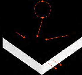
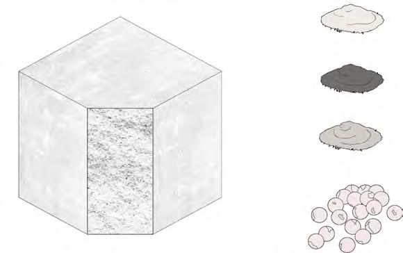
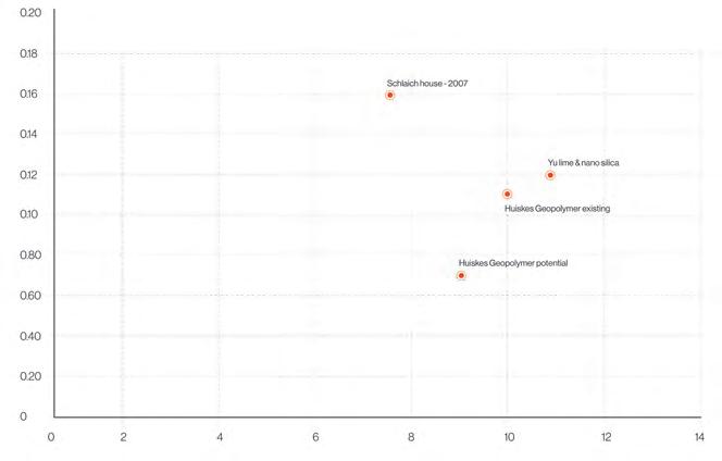
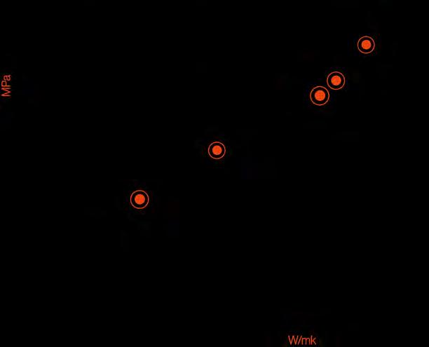
Low density, semi-aeration, & high thermal performance afford infralightweight concrete the potential to deal with both structural & thermal requirements on a single envelop layer. Offering potential for monolithic construction explored formally through continuous surface folding. And Possessing the ability to achieve thermal performance for UK compliance at a thickness as low as 500mm, depending on the mixing proportions, as shown below.
Portland cement Conductivity W/mk
U- Value Calcs


500mm 500mm 500mm 500mm Roof U = 0.07/0.5 U = 0.14 Wall U = 0.07/0.5 U = 0.14 Floor U = 0.07/0.5 U = 0.14 250mm 500mm 460mm 460mm 450mm 220mm Roof U = 0.12/0.75 U = 0.16 Wall U = 0.12/0.46 U = 0.26 Floor U = 0.12/0.67 U = 0.18
Monolithic Potential - Concrete ‘End of Life’ Considerations:
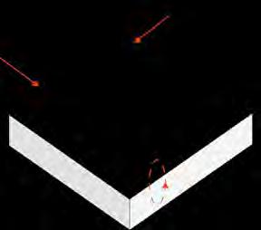

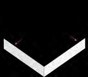
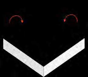
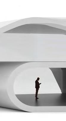
A construction process utilising as few different construction material as possible. Allowing for easy recycling of demolished concrete due to few pollutants in the demolished material. This removes the need for ‘sorting’ recycled rubble which often makes recycling concrete unviable due to being labour intensive.
1.
2.
3.
Raw materials delivered & processed.
Concrete poured
Kg/m3 Conductivity W/mk Density Kg/m3
Structure demolished
- 50 Years -
Density Kg/m3
Rubble removed from cite and processed for recycling
Plastisiser + + + Density
Geopolymer Compressive Strength MPa
Thermal Performance Vs standard reinforced concrete
Compressive Strength Vs standard reinforced concrete
Formwork removed & recycled
4.
5.
Material Research
Infralightweight Concrete
Material Research

Infralightweight Concrete
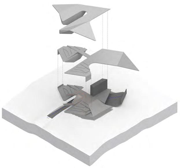
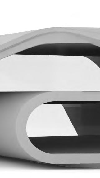
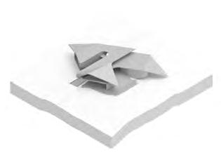
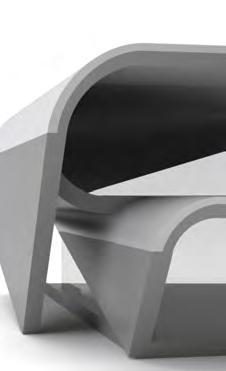
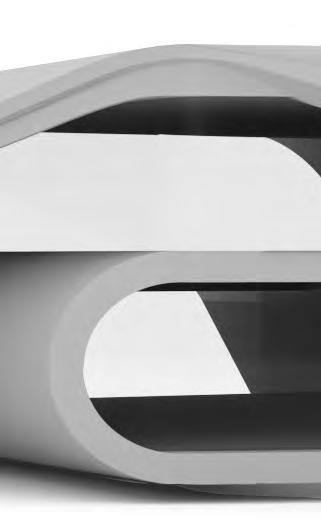
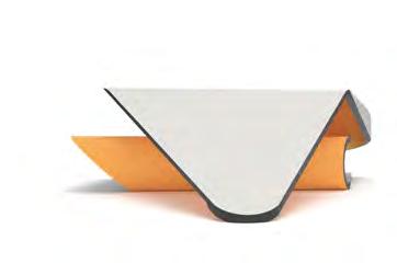
Working with infralightweight concrete to create enclosures that follow earlier brutalist influence. Expanding the original fragment to accommodate large and more complex programmes whilst using a continuous, monolithic, and thermally compliant envelope.
Shown right are infralightweight mix test, aiming to understand the thickness’s required for a compliant monolithic surface and the potential to utilise the properties of multiple mixes using a layered casting strategy.
Material Properties Fragment 1: Fragment 2:
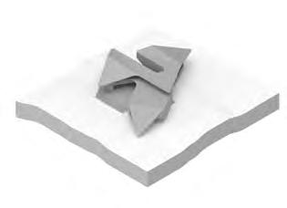
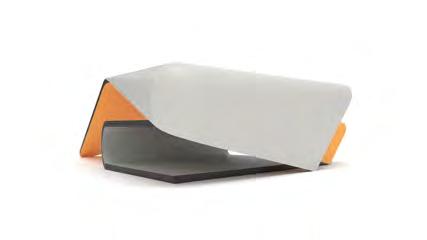
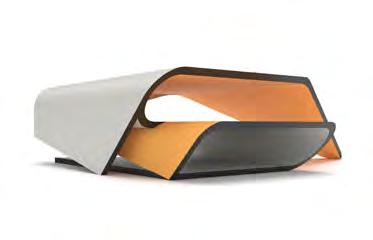
Yu - Lime & Nano silica variant:
Using the infralight concrete variant with the best thermal properties and acceptable compressive strength at present - 2016 research development. Infralight concrete with a lime & silica powder binder mix. Properties:
MULTI-ILC (Multilayer infralightweight concrete)
Utilising developing multilayer pour technology which takes advantages of the strongest properties of different infralight mixes, here suggesting an insulating structure layer & a super insulating layer thus reducing the overall thickness of the build up. Properties:
Huskli Geoplymer infralight concrete potential
Based on their research paper testing infralight mixes including geopolymers Huskil concluded their is future potential, with more testing to reach a thermal conductivity as low as 0.07 W/m-1k-1 with a compressive strength of 10MPa. Making it usable in a single layer system at thickness’s below 500mm.


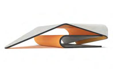
250mm 500mm 460mm 460mm 450mm 220mm Roof U = 0.12/0.75 U = 0.16 Wall U = 0.12/0.46 U = 0.26 Floor U = 0.12/0.67 U = 0.18 250mm 300mm 550mm 550mm 250mm 300mm Roof L1 R = 0.25/0.07 R1 = 3.57 L2: R = 0.30/0.12 R2 = 2.50 U=1/Rsi+so + 2.86 + 2.92 U=1/0.14+3.57+2.50 U=0.16 Floor L1 R = 0.25/0.07 R1 = 3.57 L2: R = 0.30/0.12 R = 2.50 U=1/R + 2.86 + 2.92 U=1/0.14+3.57+2.50 U=0.16 Wall U = 0.12/0.55 U = 0.22
0.12 W/m-1k-1 10-12 MPa 650-700 kg/m2 0.12 W/m-1k-1 10-12 MPa 650-700 kg/m2 500mm 500mm 500mm 500mm Roof U = 0.07/0.5 U = 0.14 Wall U = 0.07/0.5 U = 0.14 Floor U = 0.07/0.5 U = 0.14
0.07 W/m-1k-1 10 MPa 500 kg/m2
2023 Tom Bird Section 1 Advanced Architectural Design
Material Handling & Production Mass Production Influence
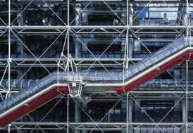
Mass Production & Standardisation
Considering how Iinfralightweight concrete may be used in an efficient construction system, that may be scaled up to enable a ‘campus’ sized intervention.
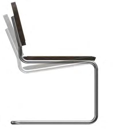
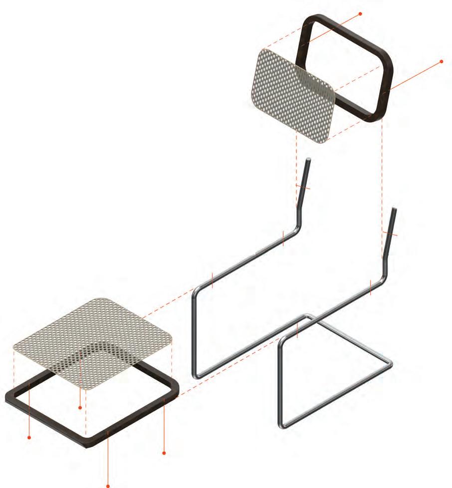
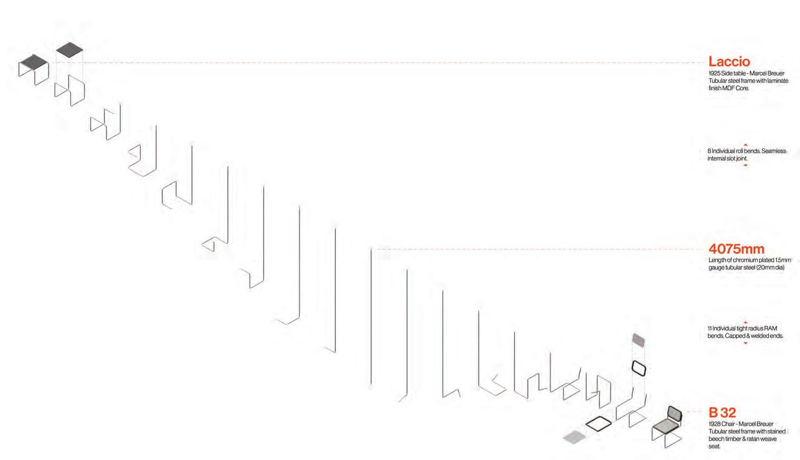
Looking first to mass production to study efficient material use & assembly. Producing a highly refined product that can be produced at scale. Initially in the form of Marcel Brueure’s B32 chair. Maximising the utilisation of steels material properties in its standardised, monolithic components.
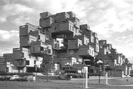
Achieving scale through modularity or a standardised kit of parts.
Below: Optimising a pre-cast concrete component to have standardised geometry, therefore allowing formwork to be reused.
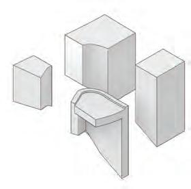
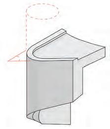
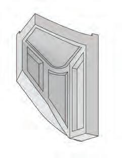
Furthermore, optimising geometry so each component uses as little material as possible.
1 2 3 4 5 6 7 2023 Tom Bird Section 1
1. Solid stained beach frame 2. Bolt fixed back rest 3. Rattan weave, adhesive fixed 4. Seamless tubular steel extrusion with chromium finish 5. Friction fit Solid steel dowel joint. See detail 1 6. Bolt fixed seat 7. Cane weave frame 8. 2mm gauge - 20mm DiaRotary draw bent Advanced Architectural Design
Standardised, Pre-cast Logic Assembly, and Transportation
Slab subdivision & Transport
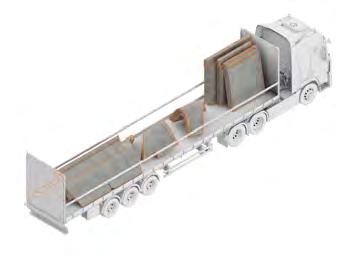
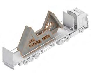
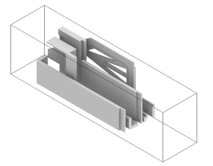
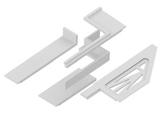
The arrangement of components for efficient transportation is considered in their geometry. Maximising the number of components that can fit in a single lorry, thus reducing the number of deliveries required to be made to site.
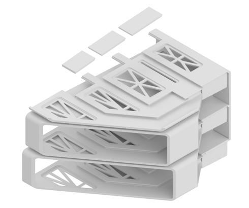
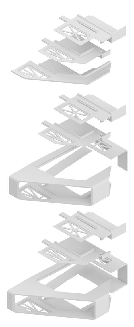
Pre-Cast Stacked & Folded Floor Slabs
Above: An early study into the use of pre-cast assembly to enclose space in a stackable module. Interlocking slabs and components are optimised for minimal material usage. They are also able to break down into sub-components of a scale that can be transported from factory to site by a standard lorry along restrictive rural roads.
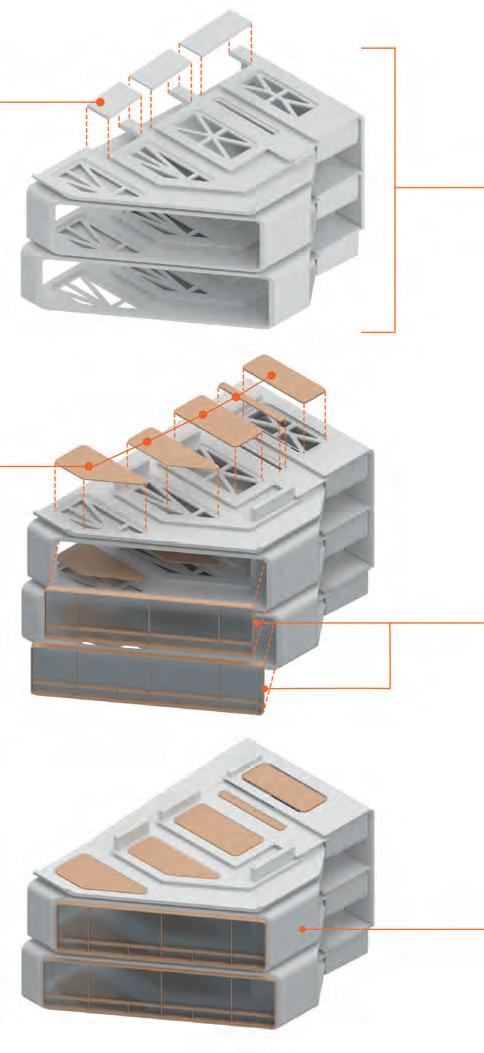
Prefabricated Timber Inserts
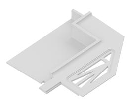
Secondary concrete elements inserted
Prefabricated ergonomic timber floor inserts
Assembled pre-cast slab system Timber curtain walling delivered on site assembled External surface treatment already applied to external surface. No further work required
2023 Tom Bird Section 1
8.5 2.9 2.5 Standard UK lorry
bed
Advanced Architectural Design
Section 2 Design & System Development
Pages: 013-017
Connection to The Landscape Arts
Frank Lloyd Wright: Edwin Lutyens:
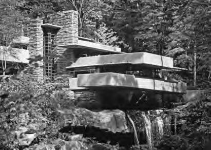
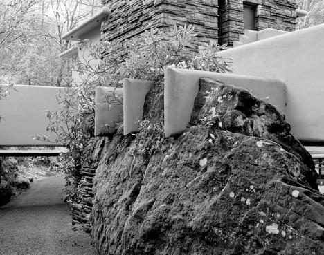

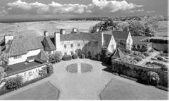
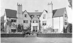
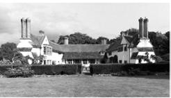
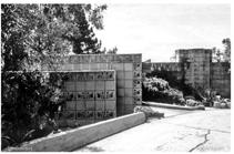
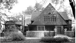
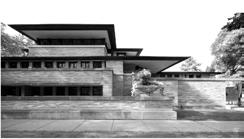
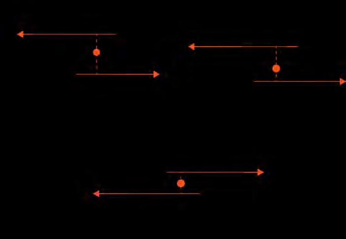
Top left: Studying the arts & crafts. Specifically, the early houses of Frank Lloyde Wrights. Examining their form in plan and identifying a commonality in offsetting 2 blocks to create semienclosed courts at either end of the plan.
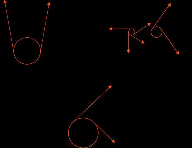
Top right: Edwin Lutyens, using a method of projection ‘fingers’ out from radial tangents, creating explosive projections into the land scape. These studies ultimately informed the plan concept shown.
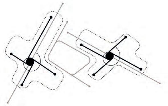
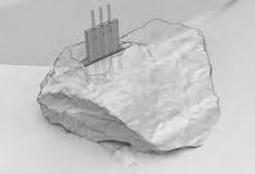
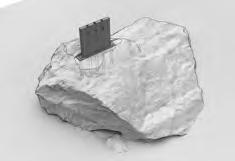
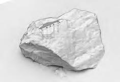
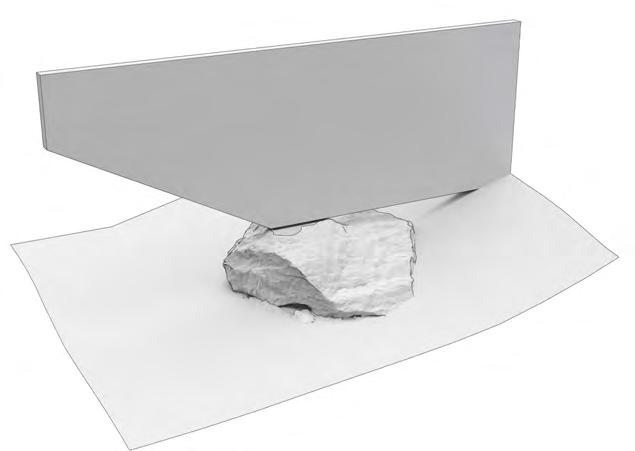
Bottom: Falling Water. Considering building directly off the landscape. Taking inspiration from foundation & roof connection details which connected directly into the boulders on
2023 Tom Bird Section 2
Advanced Architectural Design
& Crafts Influence
Global Arrangement Massing Development
Massing concept
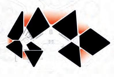
In-situ Core Pre-Cast Modules In-situ Plinth
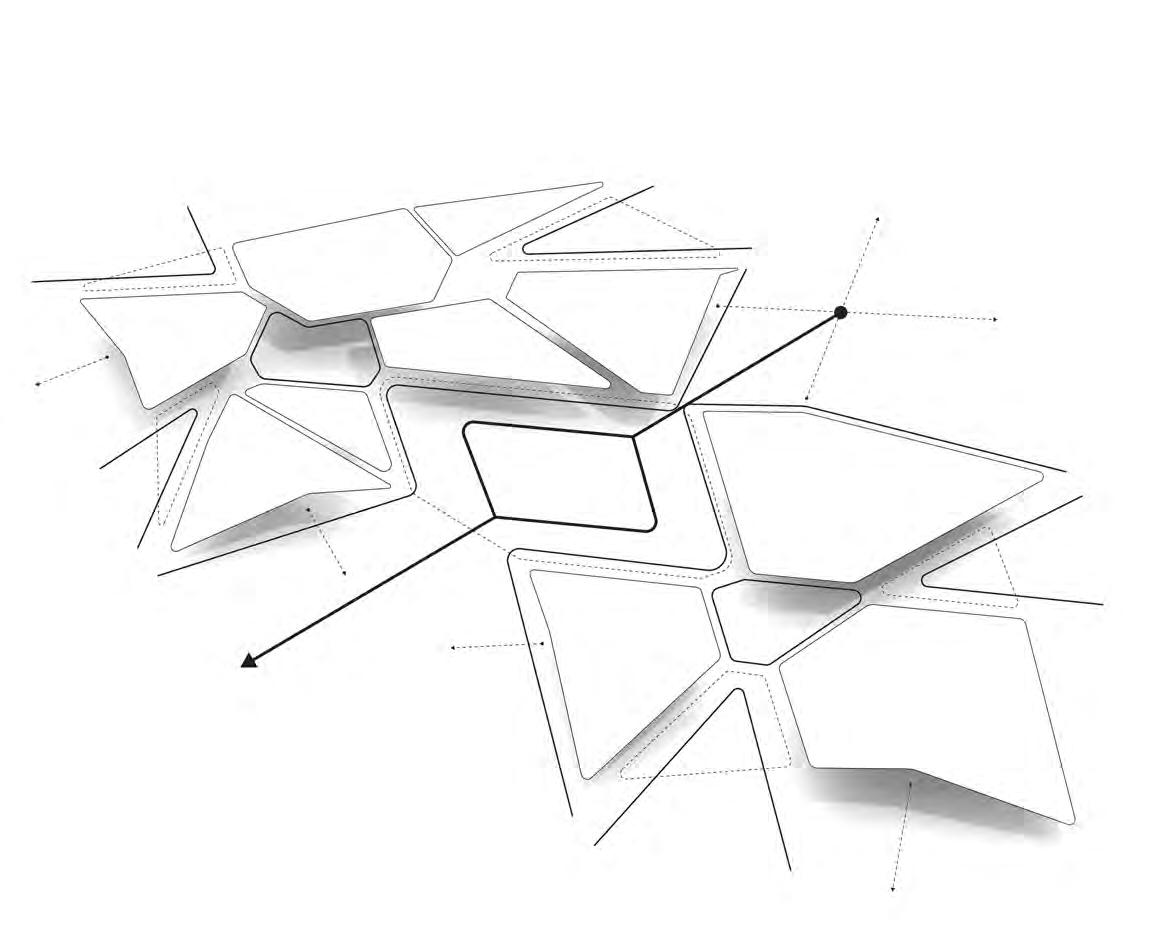
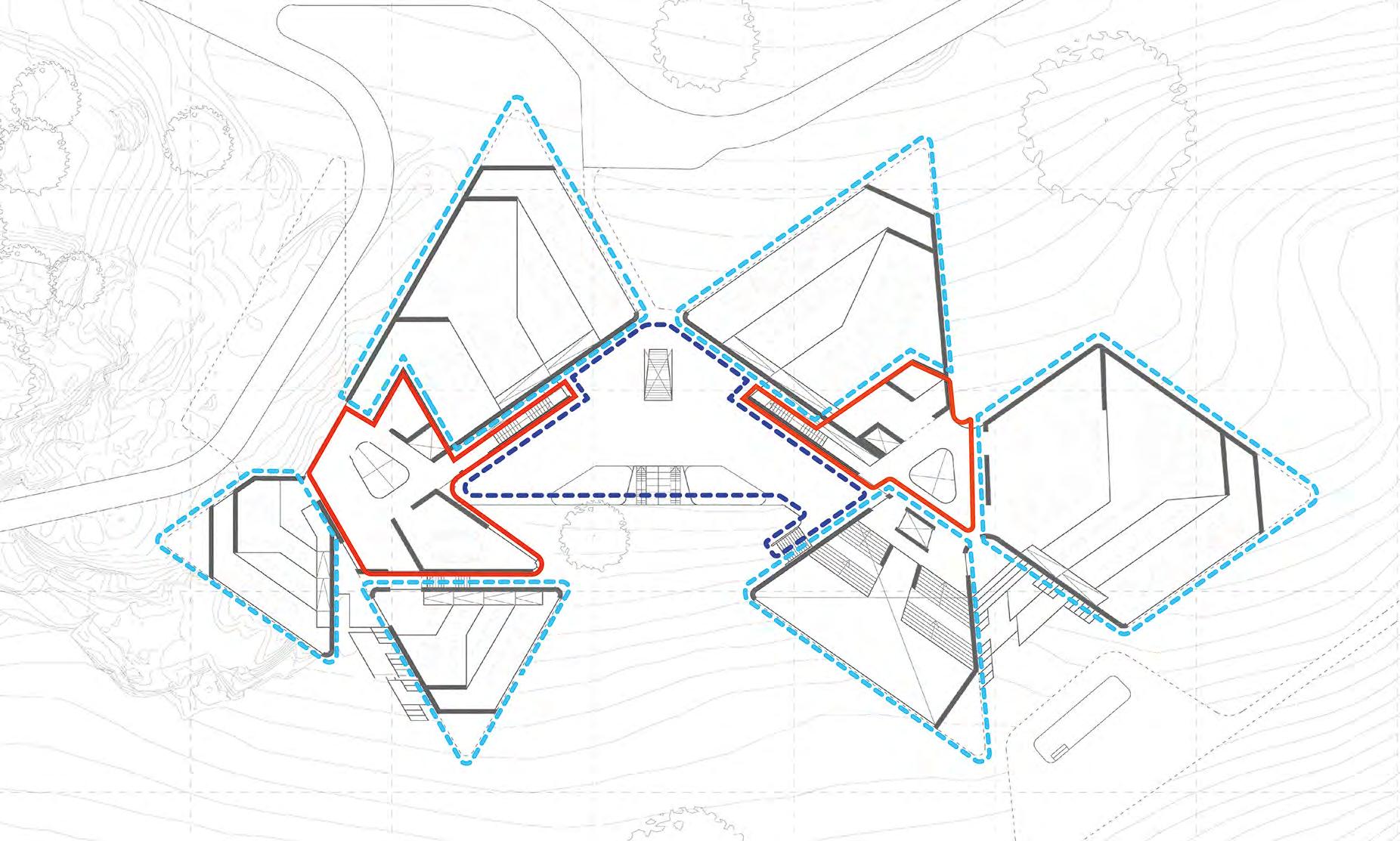
Considering the global form, connecting each workspace “Patel” cluster with a atrium core providing vertical circulation. The connecting the two clusters with a plinth. Containing all public functions & creating a change in level in the central courtyard to mediate the sloping topography.
2023 Tom Bird
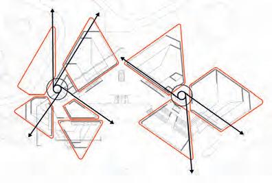
Developing upon earlier ideas coming from the arts & crafts and projecting into the landscape. Creating a “clover” in plan, that reaches into the surrounding landscape simultaneously creating cut-outs that allow the landscape to penetrate into the core of the plan. Allowing a connection between user & landscape in all areas of the plan. Section 2 Advanced Architectural Design
Typical Workspace Design
Designing For Exterior Connectivity & Productivity
User ergonomics & control:
Penalised veneer system.
Micro-perforated acoustic timber panel.
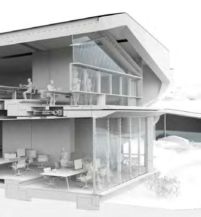
Above: Using timber inserts to cover the service pathways cast into the concrete to create a more ergonomic human interface. Timber veneer panels define working zones and provide a soft, warm touch under foot. Micro perforated panels are used on the walls and suspended ceilings to dampen the acoustics of the working environment. All other environmental control & services are contained within integrated service zones.
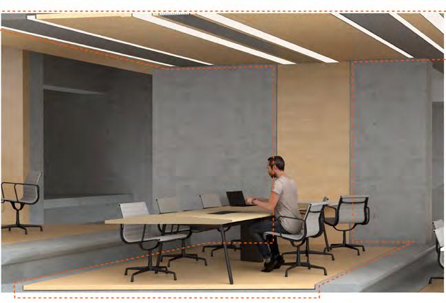
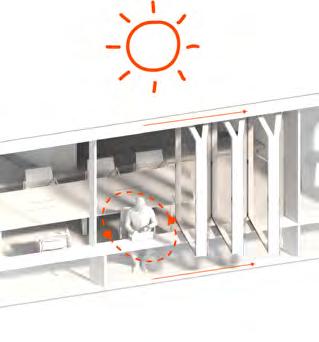
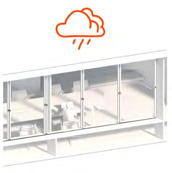
Right: Providing user control in response to the climate via fully operable façades allowing a direct connection to the landscape in the summer months. On the 1st floor, integrating a small “hotdesk” zone by deepening the horizontal support of the glazing which can be utilised when open.

Exterior connection:
Early form study: Sloping the floor & folding the roof in order to maximise the view to the exterior & deepen its penetration into the plan.
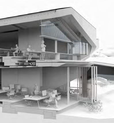
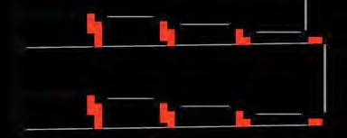
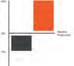
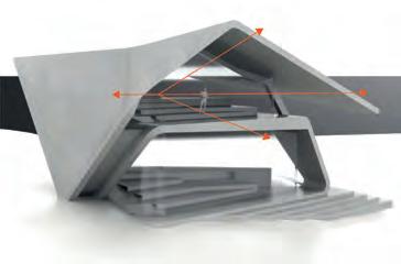
A direct connection nature is proven to cause an increase in office workers productivity, therefore the form of the workspace was resolved to feature cascading floors inspired by earlier studies.
Utilisation of a cascading section. Dropping in 330mm increments at to create stepped tires of working zones. Placing the eye levels of its sitting users above the head of those sitting in the next their down, thus not obstructing their views to the exterior Equally widening the glazed facade to create a “funnel” in plan, increasing the penetration of the exterior.
By providing this connection to the exterior an increase in user productivity can be expected.
2023 Tom Bird
Ground eye level 1st eye level 330mm 330mm 330mm 330mm
% Increase in productivity Accessible view to nature No view *Data from 2016 University of Oregon Cascading floor slab logic
Section 2 Advanced Architectural Design
Monolithic Structural Language Integrating Functionality Into Component Form
Component interface:
point
Solar response:
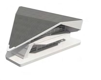
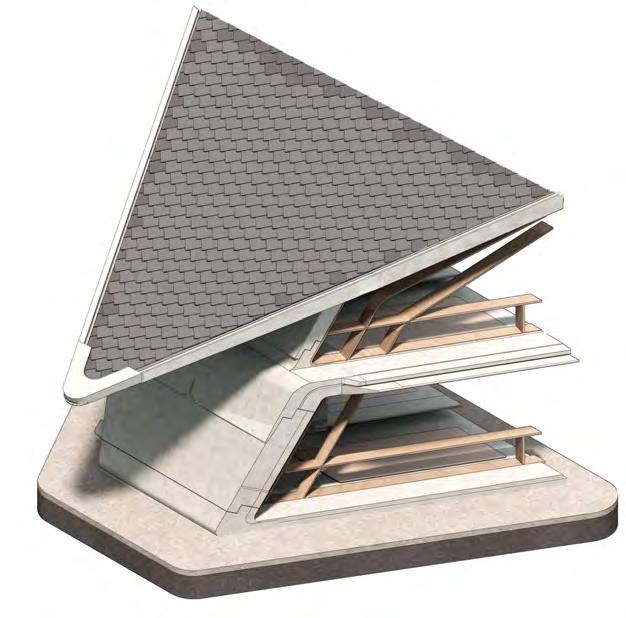
Solar shading detail integrated into the floor-slab edge. A tapered edge combined with the recess of the ground floor curtain walling provides shading from direct sunlight during summer months. The overhang of the roof provides the same coverage to the 1st floor.
Surface water management:
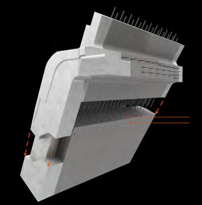
Expressing component connections with lapped joints allowing the assembly of components to read with a controlled seam. Additionally the tapered overlaps direct waterfowl down the envelopes surface a help mitigate water ingress between components.
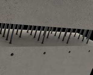
The step of the lapped joints also defines the +ve & -ve layers of the internal rebar connections & shield the small connection holes on the finished faced giving a cleaner, uniform finish.
Cement injection rebar joint:

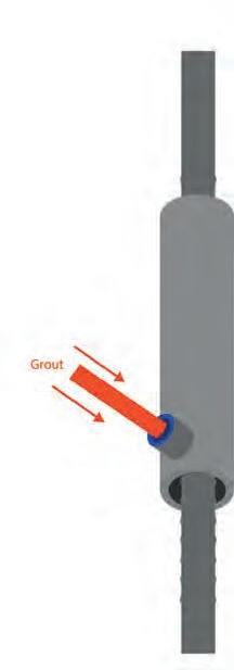
Connecting the steel rebar reinforcements of components using mortar injection joints. These offer a discrete & concealed connection between components allowing the expression of component interfaces as a single thin seam. Additionally allowing rapid assembly on site
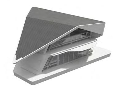
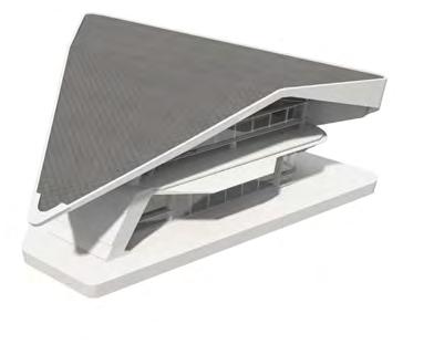
Alternate edge details provide optimal shading based on the orientation of the module. Extended or cut-away to make sure maximise natural light may enter the work space, yet shading is provided when the sun it as its highest point relative to the facade orientation.

Raked finish concrete forming channels for vertical water flow.

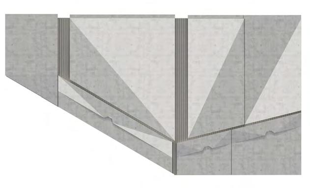
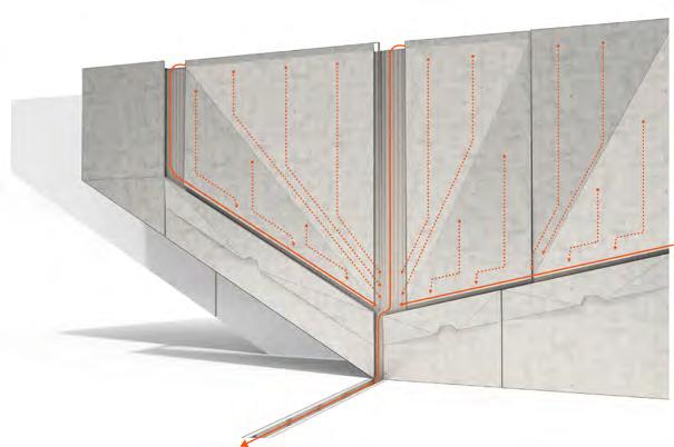

Utilising sloping geometry, ridges, & channels to direct water in the horizontal axis along vertical surfaces. High exposure to strong prevailing winds on site mean that rainfall will frequently drive into large monolithic façades.
Exerting control over the flow of this water down the facade provides control over its degradation & weathering patterns.
2023 Tom Bird
Water drip detail Roof support Water drip detail
Strip Foundation
1pm Sun
N E S W
Injection
Rebar sleeve
Section 2 Advanced Architectural Design
Design Genesis Global Design Development
Forming the typical module
Starting the design process by forming space through continual surface folding. Manipulating a single plane of infralightweight concrete in both horizontal, vertical, & oblique directions to create an enclosure that is optimises for working & a connection to the exterior landscape.
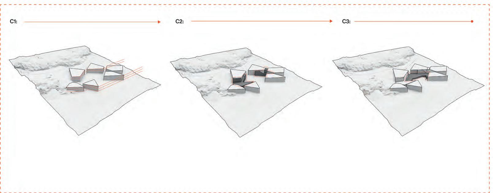
Orientating clusters of modules:
Continuing to fold & taper the single plane to form a second story with an overhanging roof form. Aiming to maximise the functionality of the folded concrete by providing integrated solar shading & openings that are optimised for allowing exterior views to penetrate deep into the enclosures plan.
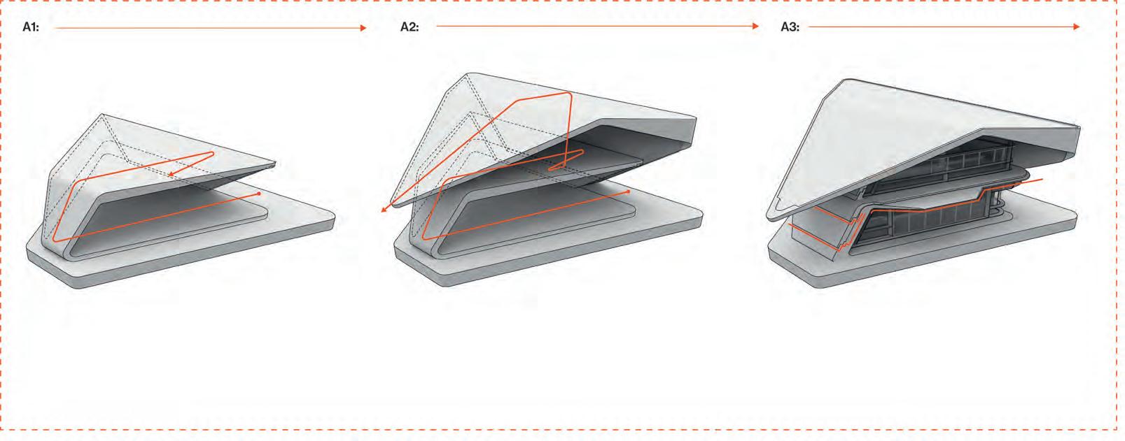
Finally, Subdividing the folded surface into an assembly of pre-cast components that can be prefabricated & assembled on site. Additionally, refining the integrated solar response by manipulating the geometry of the slab edge & integrating water management logic into component joints.
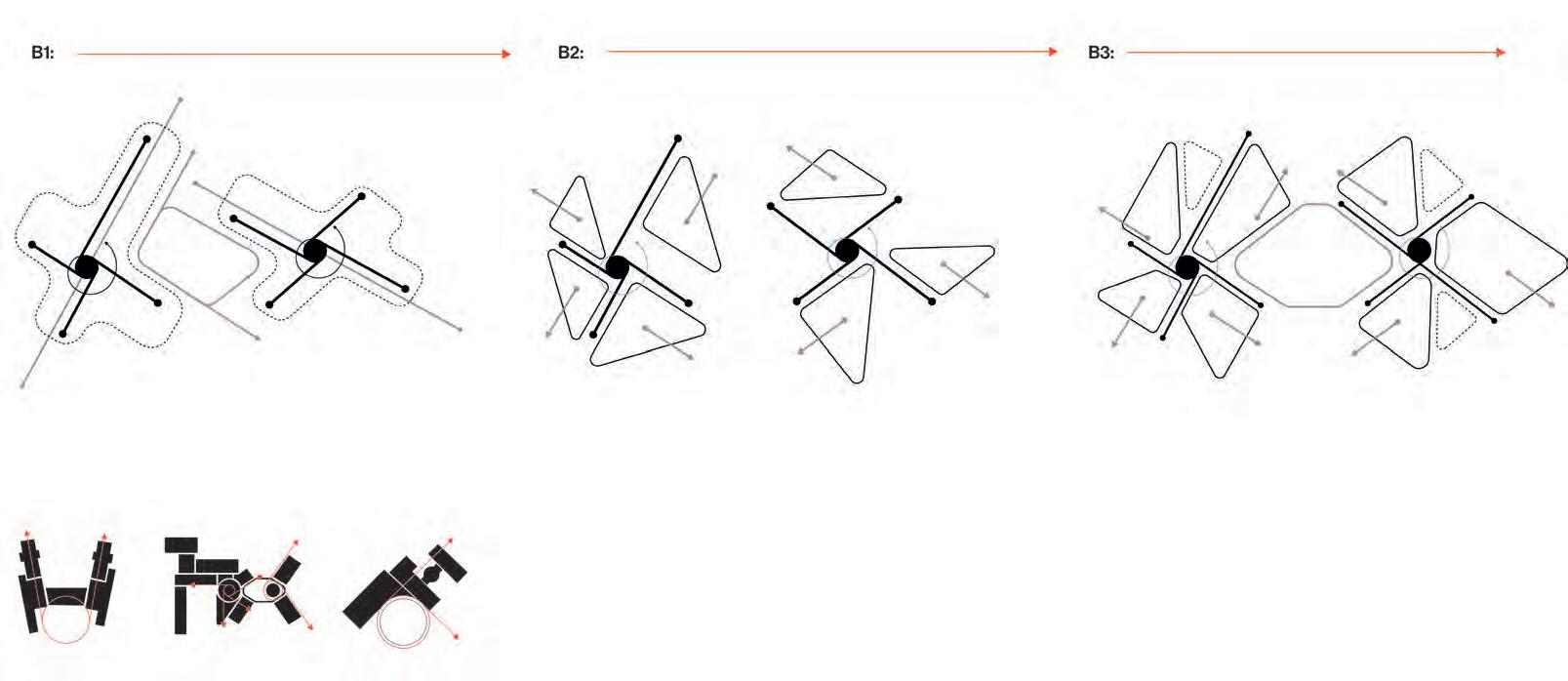
Taking strong influence from arts & crafts principles. Specifically the plan formations of Edwin Lutyens, which have “fingers” reaching into the landscape. Orientated with a logic of “Radial Tangents”, as shown below. Here developing a similar system suited to my site.
Firstly Generating two points from which “radial Tangents” can emanate, then positioning these tangent to form & enclose a large central courtyard space, much like the plans of Lutyens.
Next orientating the modules along these tangents to give views out towards the landscape, unobstructed by any other module.
Finally, chopping & scaling the modules to better form the central courtyard & connect at the central points of the radial tangents. Additionally, forming cut-outs around the plan that allow the landscape to ingress into the plan and reach the core, therefore maintaining a connection to the landscape in all areas of the plan.
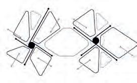
Adjusting the height of the modules to align with the topography of the site. Creating 3 set levels across all modules.
Connection all modules wither vertical circulation. Primarily consisting of 2 core atrium’s placed upon the original centre of the radial tangents.
Finally, connecting the two clusters of modules with a plinth. This plinth also mediated the sloping topography of the courtyard, creating a more accessible flat, stepped landscape.
Global connection & site mediation: Direction of topography Direction of topography Central Courtyard Defined courtyard Cut-outs -3.5 0 3.5 3.5 7 2023 Tom Bird
Section 2 Advanced Architectural Design
Section 3
Detailed Design
Pages: 018-025
Structural Brief
Responding to Project Objectives
Driving structural design considerations:
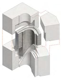
Defining the driving factors to which the projects structural system must respond. Focusing on the construction system & logistics, expressed structural language, & how the building mediates the landscape.
Standardised Components
Pre-cast Modularity
Landscape Intergeneration
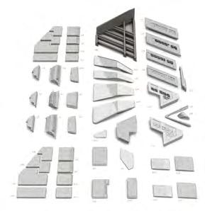
Standardising as many components as possible with the view to re-use a single assembly of high quality formwork again. This being a cost effective & certain less material waste in the construction process.
Language: Expressed Component Assembly
Celebrating the points of component connection as an expressed language of pre-cast concrete. Additionally, developing the joint to have maximum functionality by also managing water flow on the surface of the envelope.
Language: Monolithic Intent
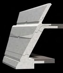
Aiming to use a near monolithic buildup to reinforce the design approach of continuous surface folding. Performing additive casting & integrating service & surface finish features into the concrete component to create a multifunctional buildup tat still performs like a single layer at junctions & corners in the overall building form.
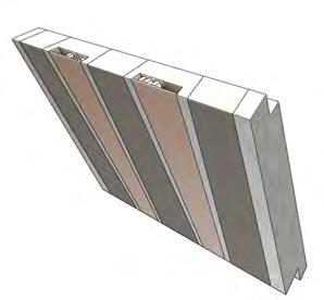
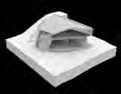
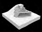
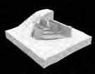
Delivery to Site
Utilising a precast system due to the benefits of prefabrication. Therefore, conducting as little work as possible on site and minimising the impact of the surrounding landscape, wildlife, & community.
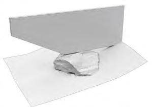
Creating a flexible foundation system that is able to navigate rock formations & steep topography that is typical of the Peak District without the need for heavy groundwork & damage to the existing landscape.
Language: Continuous Surface Folding
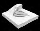
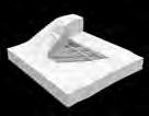
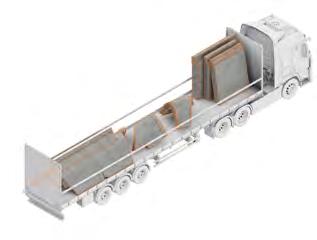
Ensuring all pre-cast components are a eligible size to fit on a standard lorry bed. Therefore, easily able to navigate the restrictive roads around the rural site. Additionally, creating a system that may be scaled & deployed to multiple sites if effective.
Rabid Assembly
Ensuring a rapid assembly of pre-cast components, again to minimise disruption to the surroundings. Specifically, work requiring heavy machinery typically associated with casting & movement of large concrete components. Instead using smaller components which can be handled by smaller machinery.
Aiming to express the monolithic potential afforded by the use of infralightweighht concrete through a language of continuous surface folding. Utilising folds to create unique spatial qualities and develop spaces with maximum connection to the exterior.

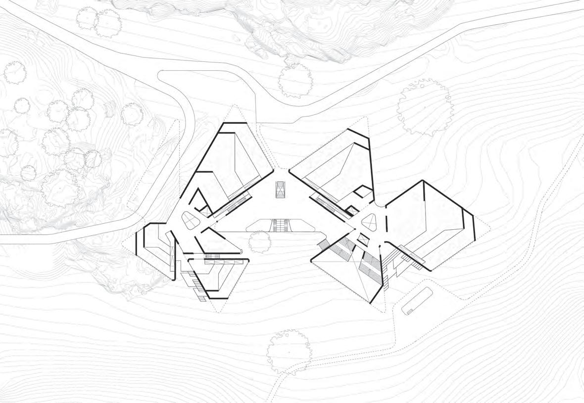
Global Form
Allowing for the reaching ‘clover’ form to materialise. With the ability to provide sufficiently large openings to capitalise on the connection to landscape the global form is providing.
2023 Tom Bird Section 3 Advanced Architectural Design
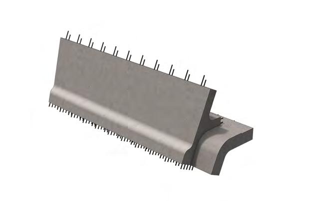
Pre-Cast Infralightweight Concrete Mix Properties & Additive Casting
Infralightweight concrete material properties
Infralightweight mix variations
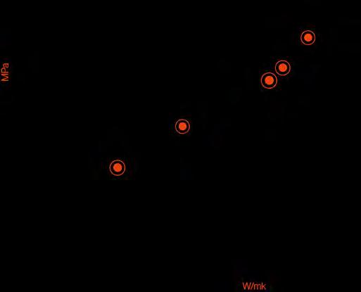
Schlaich mix
Replaces traditional aggregate with exploded clay. Replaces 30% Portland cement with Nano Scilica. Suited to reinforcement.
Nano
High compressive & tensile strength when reinforced. Good thermal performance.
Suited to spanning structure
Geopolymer mix
Thermal Resistance
Compressive Strength
Reinforcement
Additive casting:
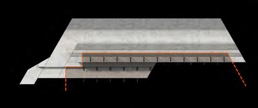
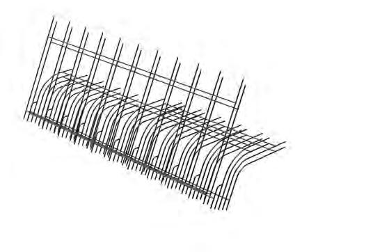
Achieving monolithic pre-cast concrete components with multiple properties: Combining multiple mixes of infralightweight concrete for more efficient utilisation of their discrete properties. Here, encasing a structurally bias mix with a thermally bias mix. Creating a component that functions as-if monolithic in the envelope. But caters to both structural & thermal requirements.
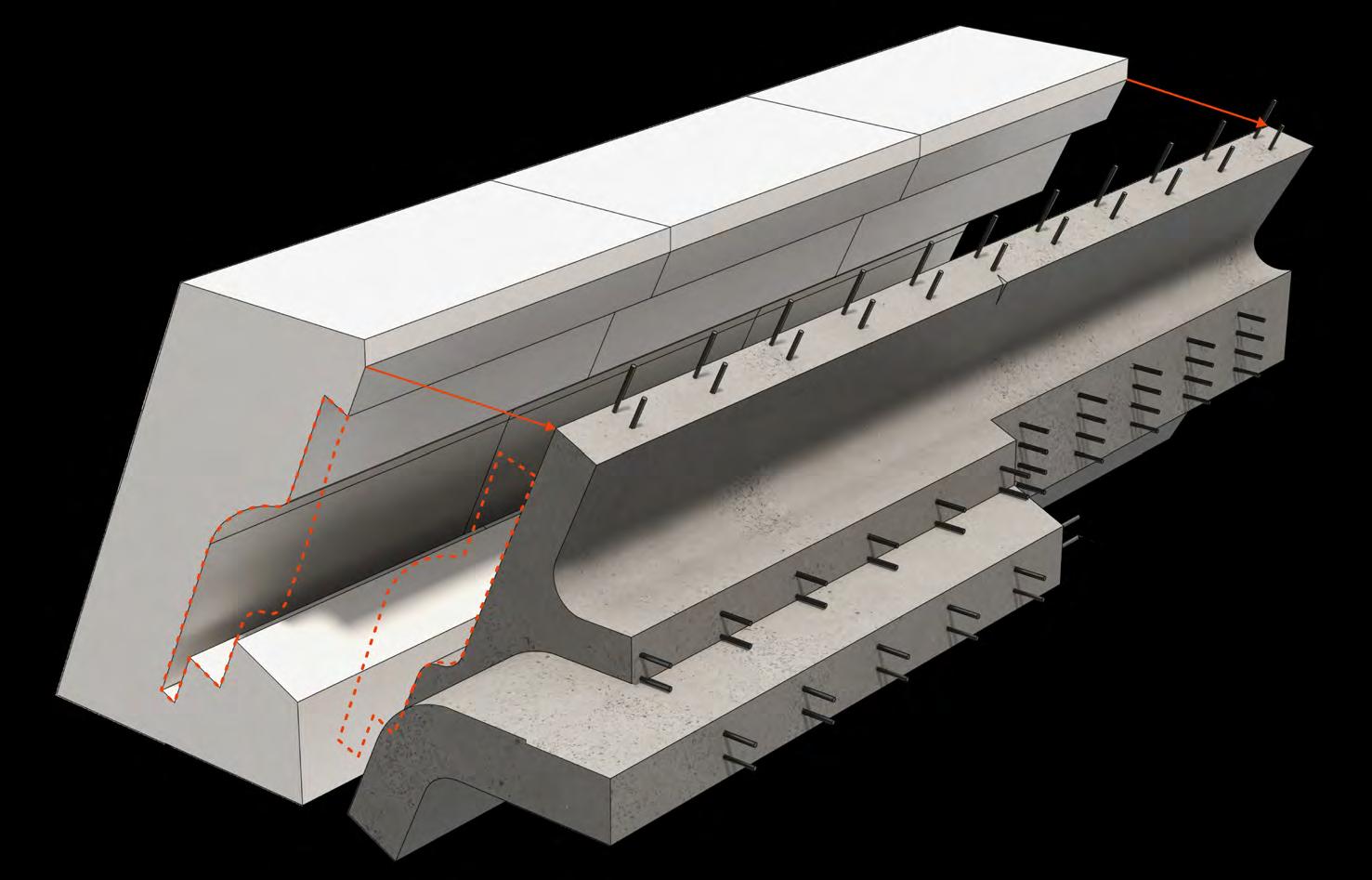
CNC milled EPS foam formwork
Reinforcement
Mix 1 (Structural bias) cast & set
Replaces traditional aggregate with exploded clay. Replaces 65% Portland cement with fly ash geopolymer. Micro aerated & surface skimmed. Very high thermal performance, low density. But compromising compressive strength.
Suited to envelope
Thermal Resistance
Replaces traditional aggregate with foamed glass. 30 % Geopolymer binder.
Very hight compressive strength & high thermal performance when unreinforced.
Suited to foundations.
Mix 1 structural core of component
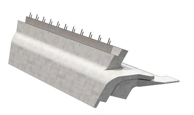

Thermal line of encasement:

Mix 2 (Thermally bias) additively cast encasing structure
 2. Geopolymer mix
Scilica mix
1. Nano Scilica mix
3. Schlaich mix
2023 Tom Bird
Section 3 Advanced Architectural Design
Pre-Cast Standardisation
Flexible & Re-usable Formwork
Degrees of Standardisation
Fully standardised component:
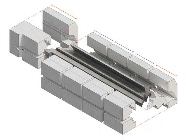
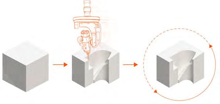
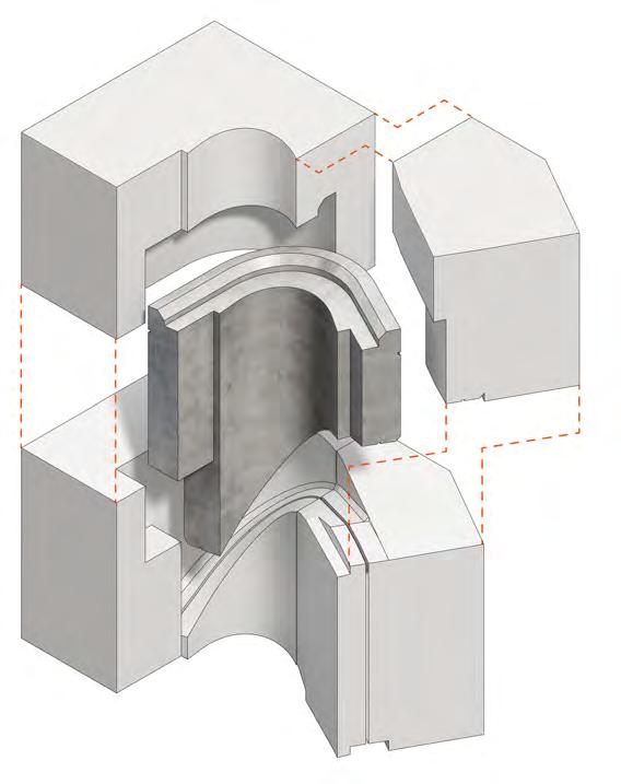
Utilising fully standardised components where possible. Formed from re-usable CNC milled EPS foam formwork. Re-use of formwork makes more complex casting geometry viable as production resources can be put into fewer, higher quality formwork elements.
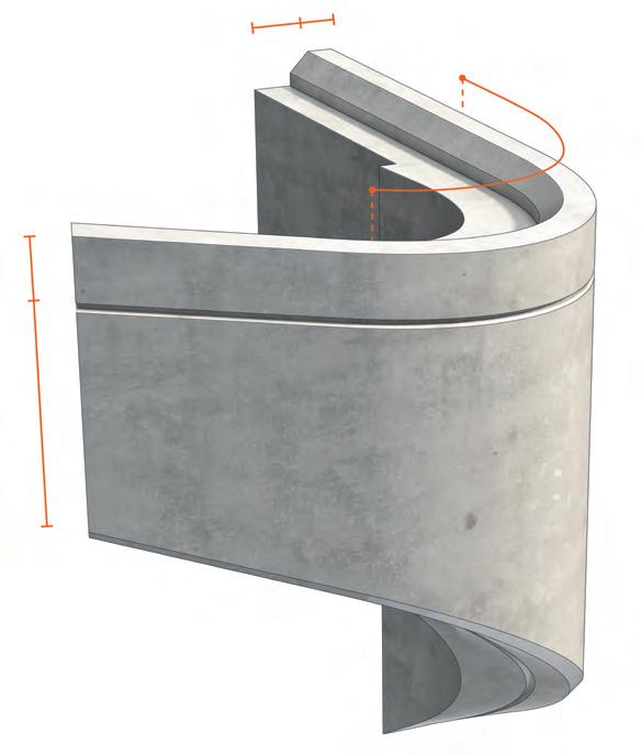
Standardised component with uni-directional variability
Where flexibility is required in component geometry in a single direction, the benefits of standardisation may still be utilised though the use of modular formwork. Increasing or decreasing the number of modules to vary the length of an extrusion in a single direction.
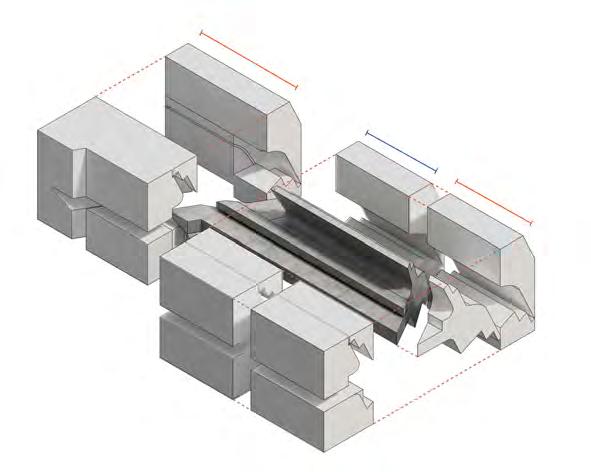
Incrementallyvariablealongextrusionprofile
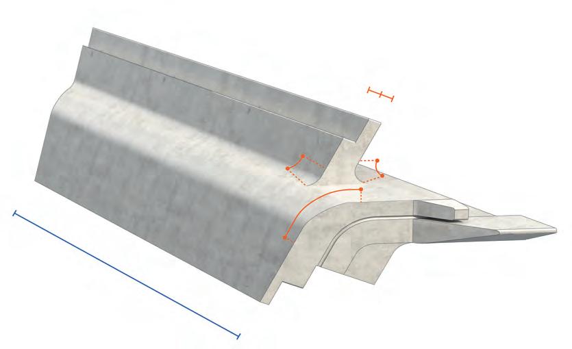
Fixed R=Fixed Fixed EPS foam 5 axis CNC milling Reusable formwork Lengthened variation: Wall - floor interface component: Roof corner component: Standard variation: Fixed Fixed Variable Fixed Fixed
Identicalformworkincrements
Fixed R = Fixed Water drips integrated into component geometry Water drips integrated into component geometry Solar shading integrated into component geometry 2023 Tom Bird
Section 3 Advanced Architectural Design
Component Transportation Pre-Cast Assembly Solution
Lorry-bed Transportation


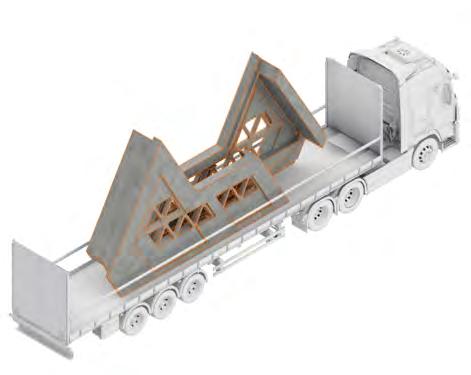
Ensuring all pre-cast components are a eligible size to fit on a standard lorry bed. Therefore, easily able to navigate the restrictive roads around the rural site.
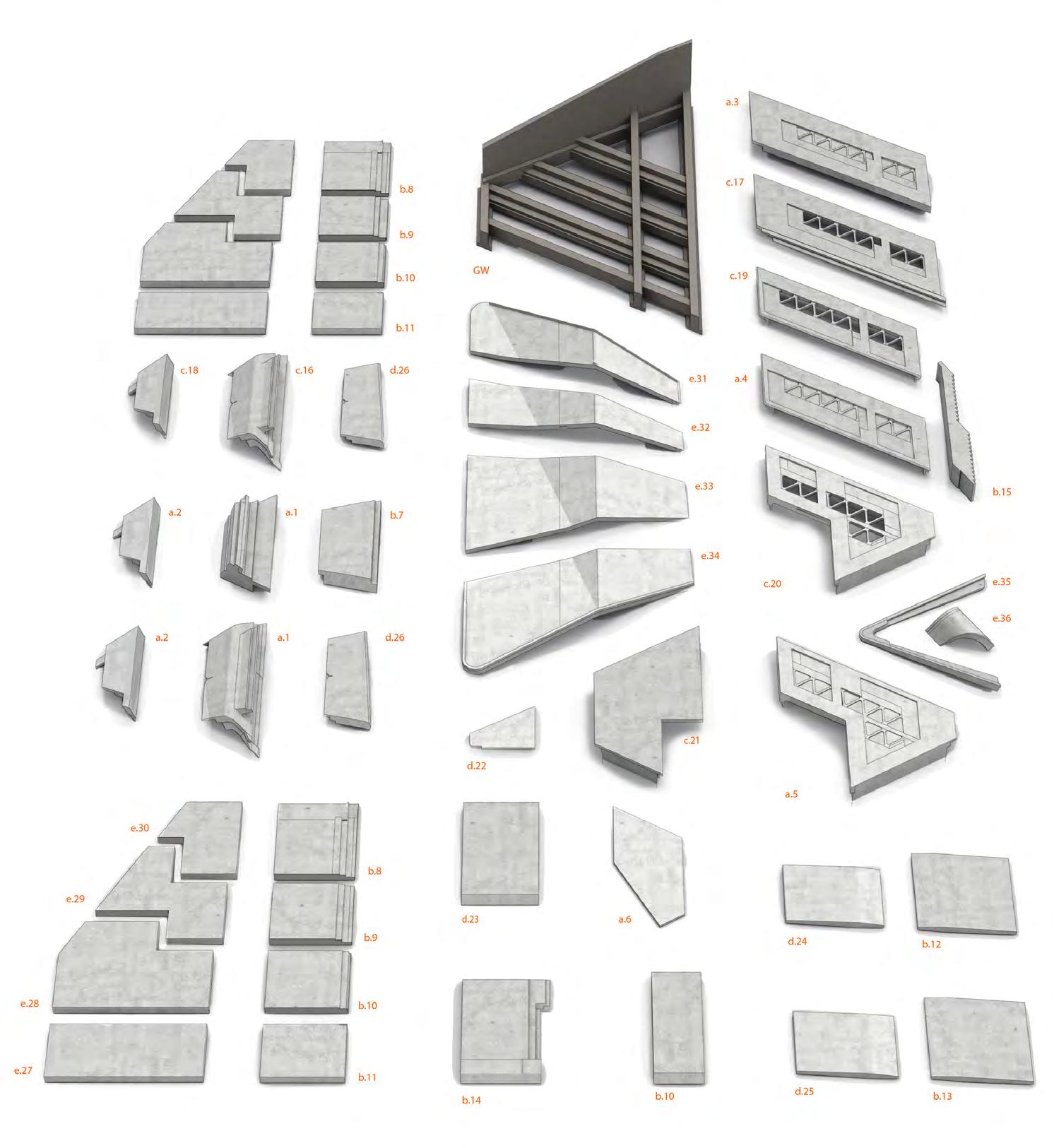
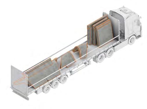
When efficiently loaded onto lorries, only 11 trailers are required to transport all required pre-cast components to site. Therefore, creating minimal disruption to the local road network & wildlife.
2023 Tom Bird
Section 3 Advanced Architectural Design
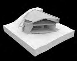
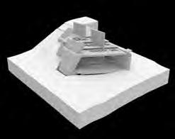
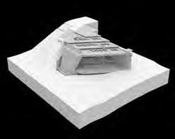
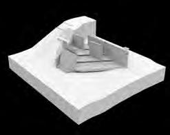
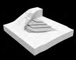
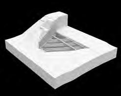
Component Assembly
Rapid Assembly Sequence
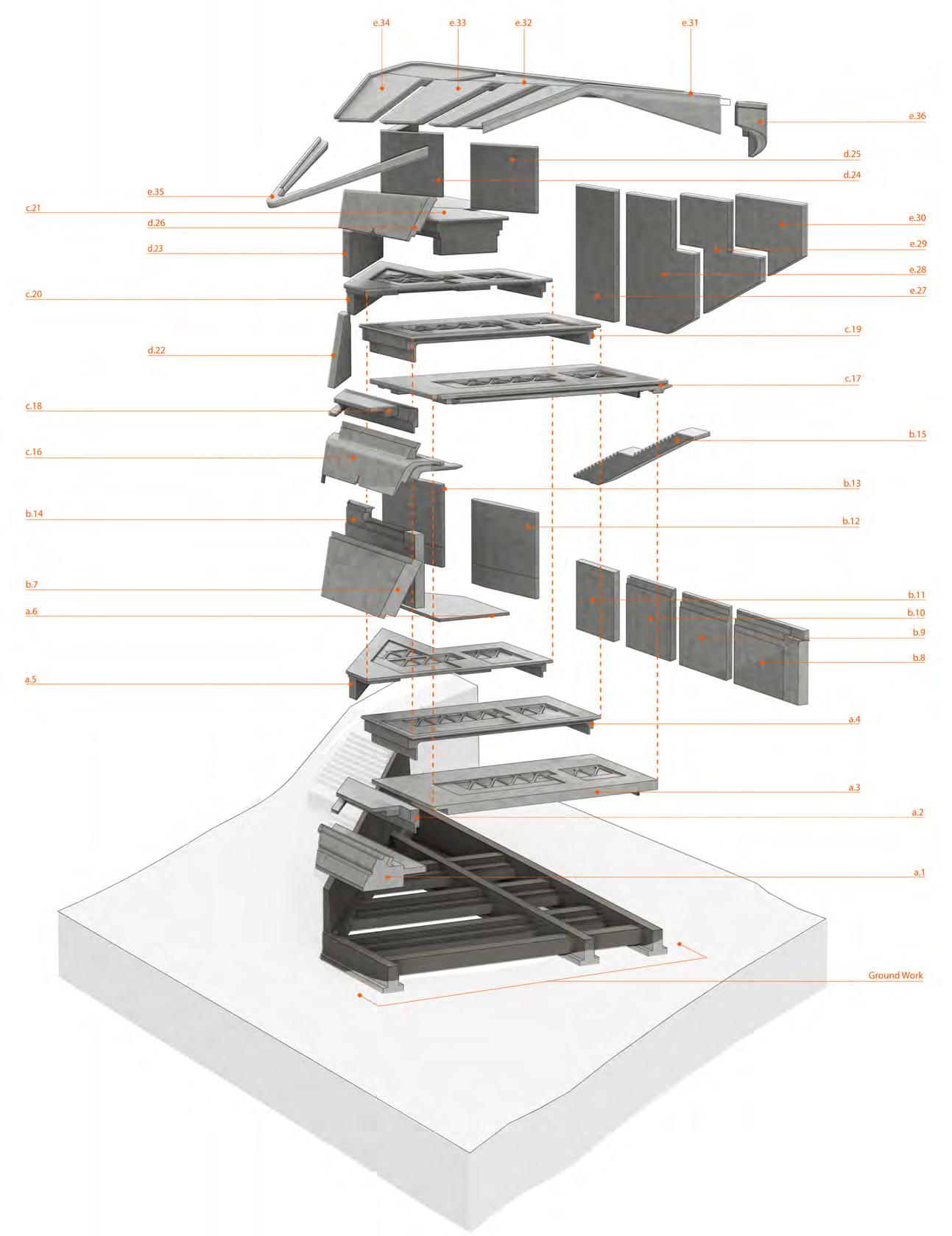
Bespoke groundwork is completed for the site of each modules before Pre-cast components are delivered.
Construction speed is determined by the linking of rebar with injection mortar joints. The foundation - ground slab interface contains the most connections thus ta
Injection mortar joints can be set within 1hr with infra-red assistance allowing for the rapid assembly of pre-cast components on site. All b & c
Interior & exterior surface finish are pre-applied to each pre-cast component, therefore once assembled only roofing & fit-out work is required for
 Ground Work
Phase A
Day 1
Day 2
Day 3
Phase B
Phase C
Phase D
Phase E
2023 Tom Bird
Module Assembly Sequence:
Section 3 Advanced Architectural Design
Structural Strategy Encased Structural Frame
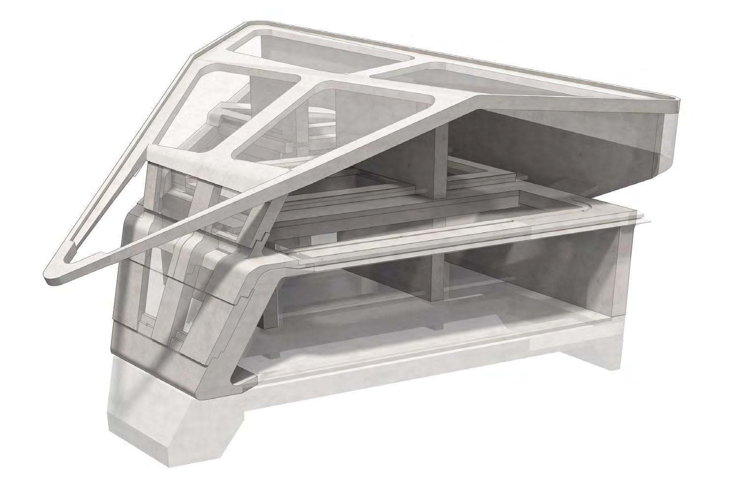
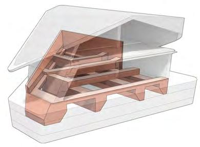
Load Distribution:
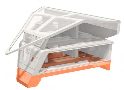
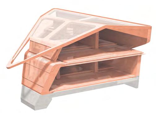
Encased Structural Skeleton.
Working with additive casting, when assembled the combination of pre-cast components form an encased structural skeleton formed from infralightweighht mix with greater structural properties.
Three vertical points of structure are formed from walls at the extreme with a central spline, across which reinforced beams integrated into the floor slabs span.
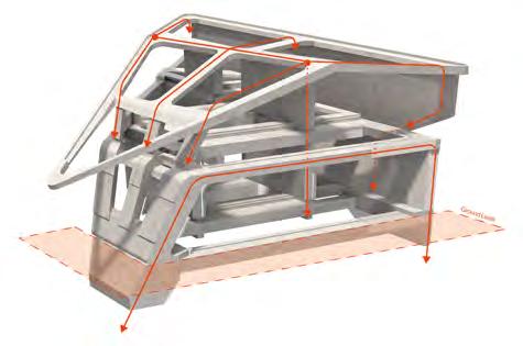
Basic load paths:



Typical Foundations:
Infralightweight Concrete Mix Allocation:
Structural frame - Mix 1
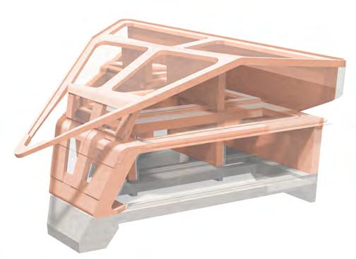
Additively cast encasing envelope - Mix 2
Foundations - Mix 3
Thermal Resistance
Compressive Strength
Reinforcement
Thermal Resistance Compressive Strength
Reinforcement
Thermal Resistance Compressive Strength
Reinforcement
In-situ reinforced strip Foundations Central spine horizontal support Spanning floor beams Points of connection between pre-cast components Spanning roof support beams 2023 Tom Bird
Section 3 Advanced Architectural Design
Material Usage
Infralightwight Concrete, Timber, & Slate
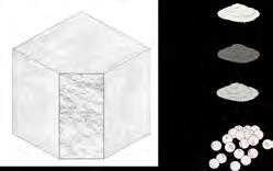
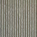
Infralightweight Concrete:


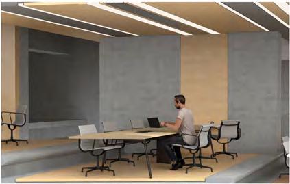
Timber Systems
Utilising a prefabricated engineered timber curtain walling system to provide contrast to the concrete envelope.
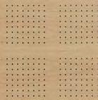
Using varying types of engineered timber veneer panels on the interior. Utilising a structural panel to create the floor infill. Using micro-perforated acoustic panels to on vertical & ceiling surfaces to soften the acoustics of the work spaces.
Slate Shingles


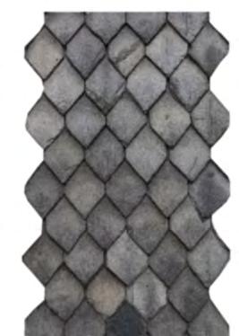
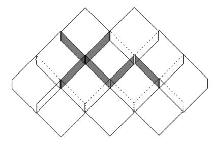
Using a diamond slate shingle system for the roof.
Typical of the local Derbyshire/ peak District vernacular and utilising local craft labour for instillation.
The ability of the overlapping pattern to cover undulating surfaces makes it fitting to the complex roof forms.
Portland cement accounts for the majority of C02 in concrete production. Due to containing geopolymer & pillaster substitutes, infralight uses much less thus has a less C02 intensive production process.
Surface Finish:
Polished (interior)
Raked (sub-layer) Sealed (exterior)
Micro-perforated
Engineered veneer

2023 Tom Bird
Portland cement content by weight
Traditional Infralight Exploded clay Plastisiser Geopolymer Portland cement + + + 25% 10% Section 3 Advanced Architectural Design
%
Material composition:
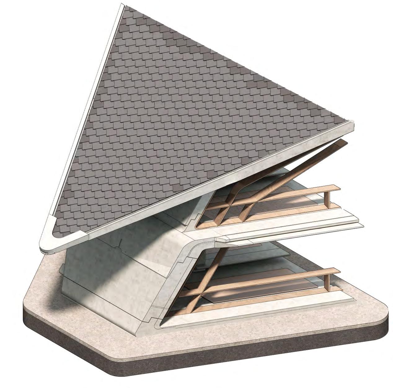
Component Assembly Envelope Build-up
Module fragment illustrating typical envelope composition & integration of structure, services, & internal & external finish.
Composed primarily of varying mix compositions of infralightweight concrete, Derbyshire slate shingle roofing, & hardwood timber inserts.
Typical roof - intermediate floor - ground detail. Specific variation shown proportions on a north facing module, therefore with suppressed solar shading elements.
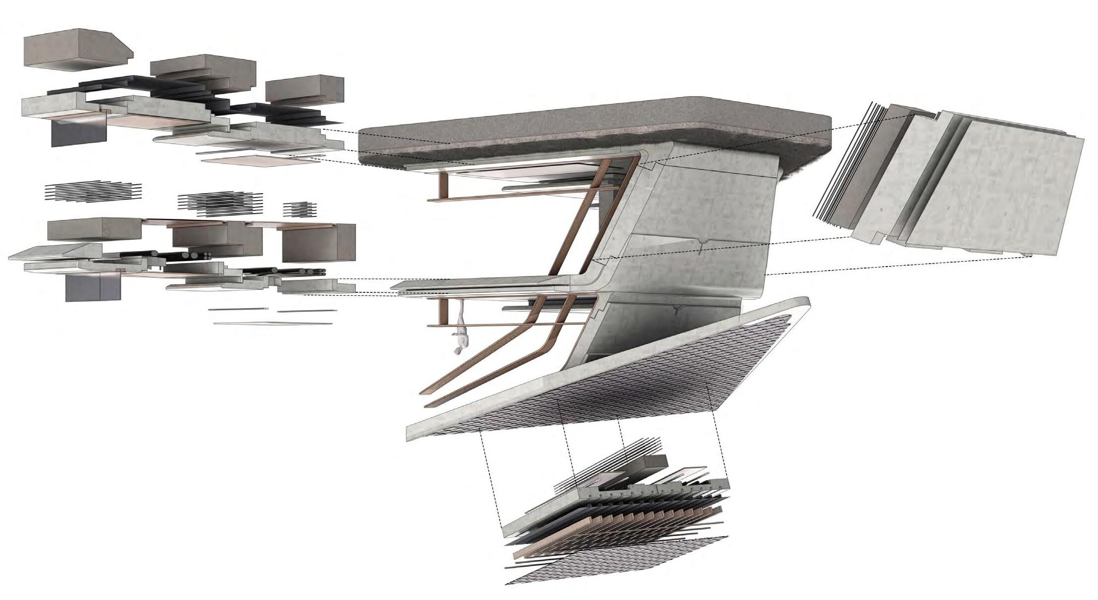
Key: 1. Veneer flooring panel 2. Timber framed curtain walling system walling component 3. Perimeter vent 4. Mix 2 slab edge detail 5. Mix 2 Pre-cast concrete component 6. Timber acoustic ceiling panel 7. Mix 1 encased structural element 8. Integrated lighting 9. Ceramic glaze finish 10. Timber acoustic panel 11. Sealant 12. Mix 3 in-situ cast foundations 13. DPM & vapour control membrane 14. Steel re-bar reinforcement 15. Timber battens @600mm Centres 16. Timber rafters @400mm Centres 17. Diamond lapped slates 18. M&E Services 19. Timber curtain walling system 20. Suspended timber ceiling 21. Lighting 22. Roof cap spout detail 23. Water drip detail 24. Material optimised slab zone 25. Integrated parapet 26. Integrated gutter zone 17 15 16 13 5 18 21 6 14 9 11 5 7 14 22 23 23 4 19 12 13 1. 3 19 24 3 1. 26 25 18 20 21 1. 2023 Tom Bird Advanced Architectural Design Section 3
Construction Sequence Global Project Progression
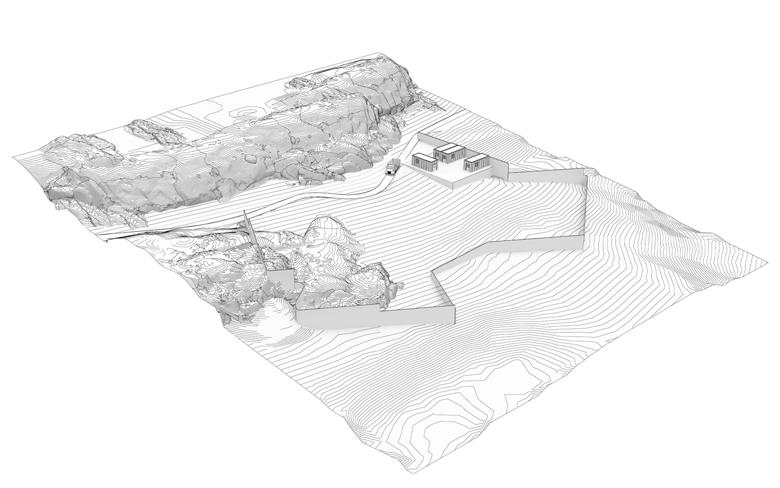
In order to prevent disruption to migrating wildlife & livestock construction will begin outside of dear mating & lambing season. This being September. Additionally, the site perimeter should be fenced off to reduce the risk of wildlife or people being injured by traversing the construction site, with a small plinth being levelled to house temporary office & site management structures.
The movement of earth & levelling takes place according to site setting out drawings provided by the architect. Additionally, attention is paid to the retention of certain areas of topography & rocky highlighted by the architect.
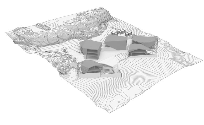
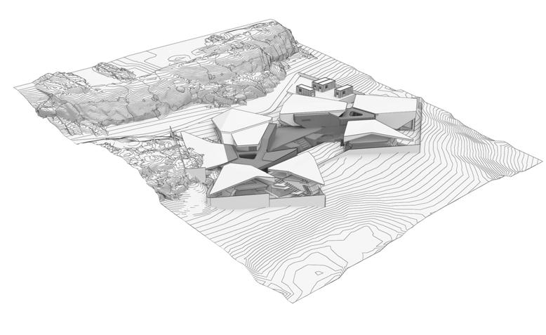
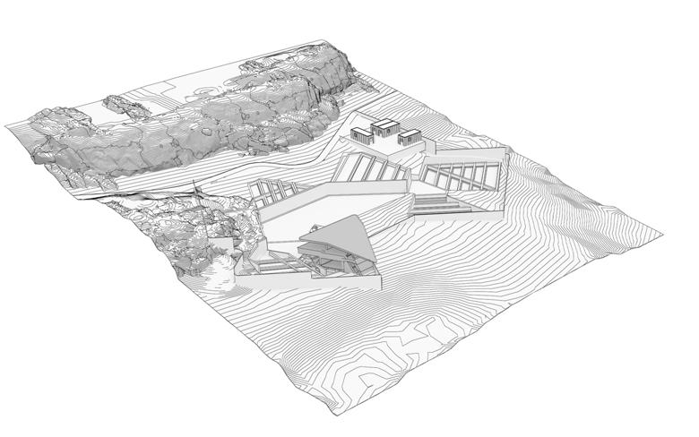
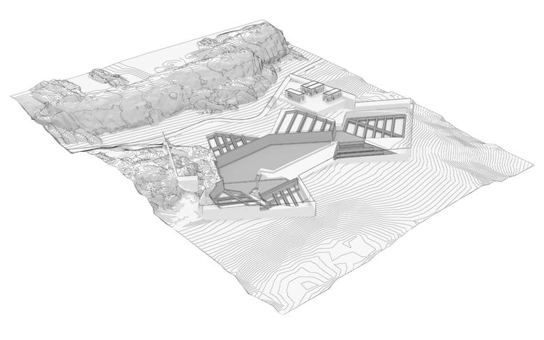
In-situ concrete working team attend site to pour strip & plinth foundations. Additionally, site levels are set with the construction of retaining walls. All cast in a the infralightweight concrete mix specified by the architect.
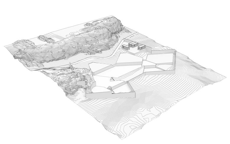
The pre-cast components for one module are manufactured, deliver, & assembled on site. Once assembled the module is surveyed & feedback is sent back to the manufacturer. The success of the initial module may them be assessed & further optimisations made to the components of the remaining 5.
The remaining pre-cast components are manufactures & delivered to site. Assembled in sequence and surveyed once again to provide data for the in-situ casting of the remaining elements and to ensure a accurate interface between pre-cast & in-situ stages.
In-situ team return to cast the cores & plinth. Subsequently, other contracting teams enter site to begin the laying of roof shingles, internal fit-out, & landscaping.
1: Establish site perimeter
3: Foundations & retention
5: Remaining module assembly
2: Excavation
4: Prototype assembly
6: In-situ casting, Roofing, & Fit-out
2023 Tom Bird
Section 3 Advanced Architectural Design
Section 4
Final Drawings
Pages: 026-033
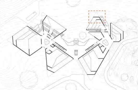
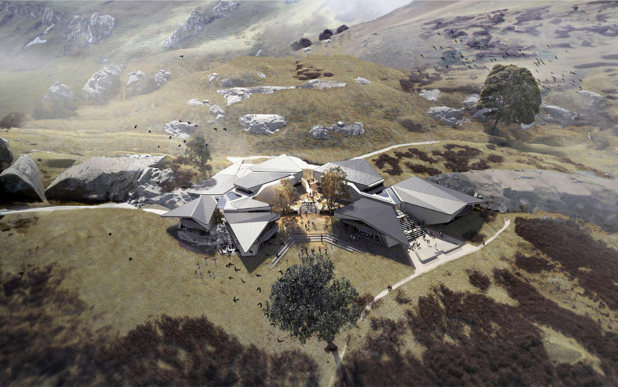 The Peak District Tertiary Assembly
Thomas Bird - Unit 14

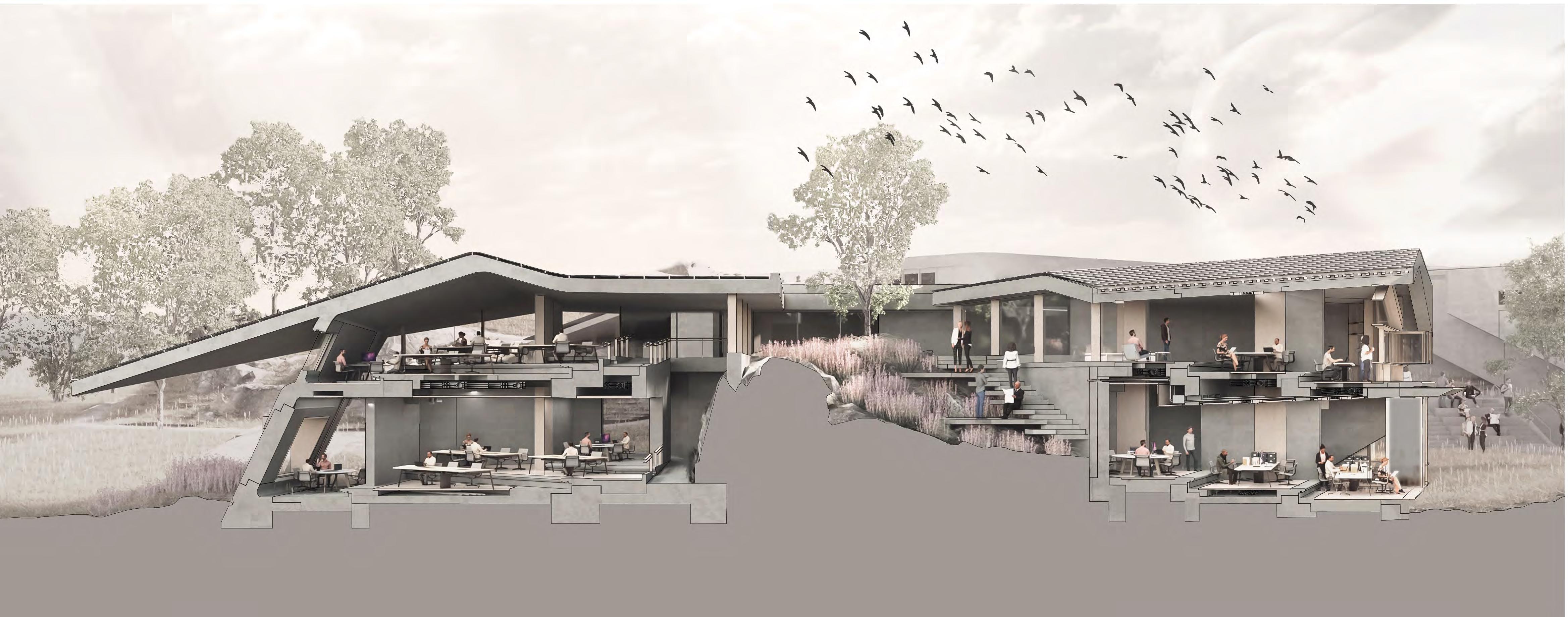
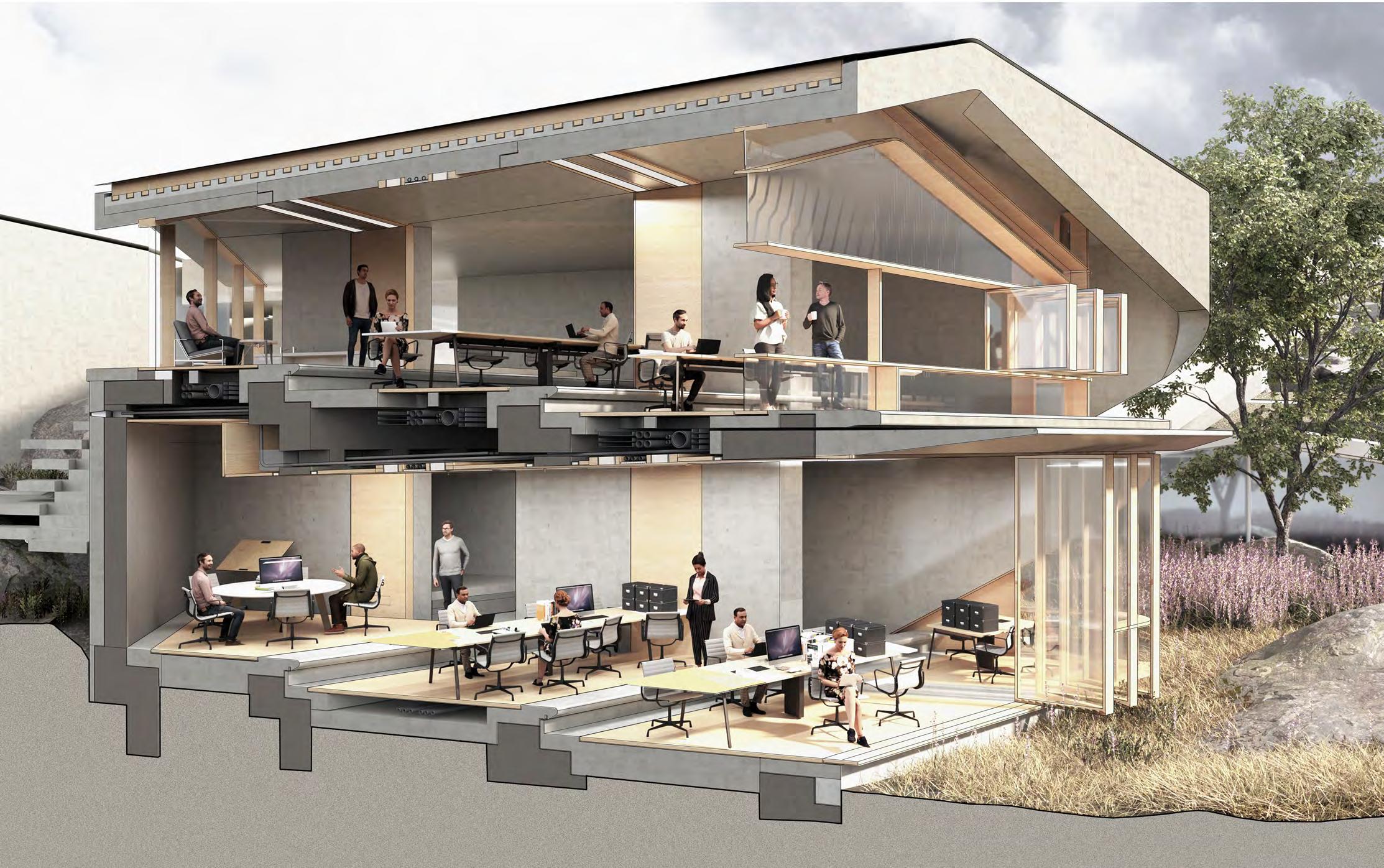
Perspective Section C-C North to South

Perspective Section B-B North West to South East

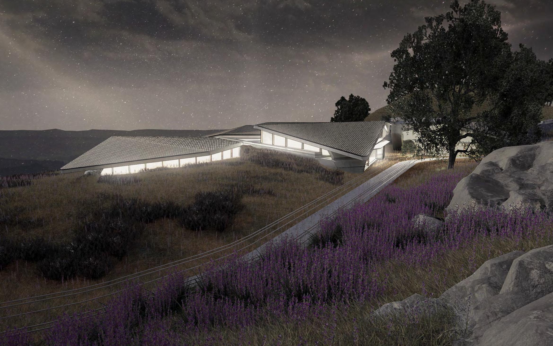
Evening Perspective View North to South


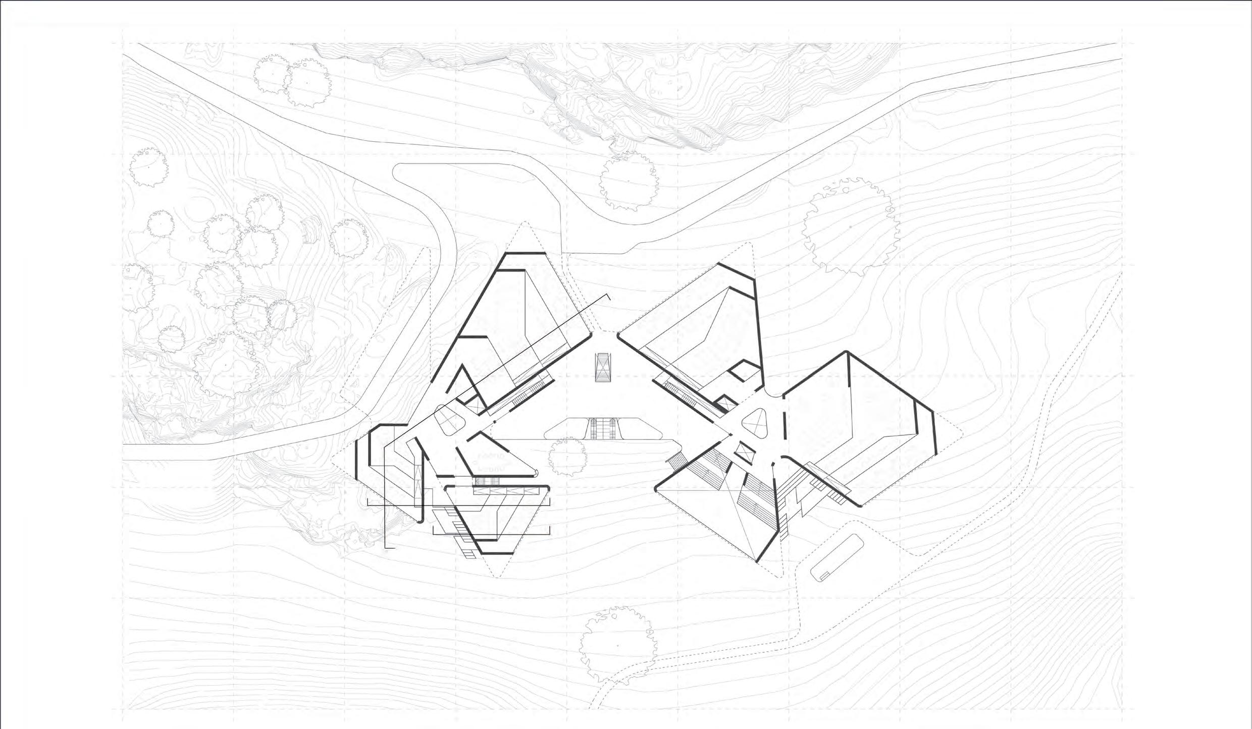
1. Reception
Cafe/ Hot-desking zone
Workshop, Bike maintenance & storage 4. Kitchen, Storage, & Server 5. Board Room 6. Atrium & Hot-desking zone 7. Working Module 8. Informal Auditorium 9. External Auditorium Stage 10. WC 11. Automated Vehicle Charging Zone A 2 3 4 5 6 10 11 7 7 B B C C A
2.
3.

Lower Ground Plan Scale 1:500 1 6 10 8 9 7
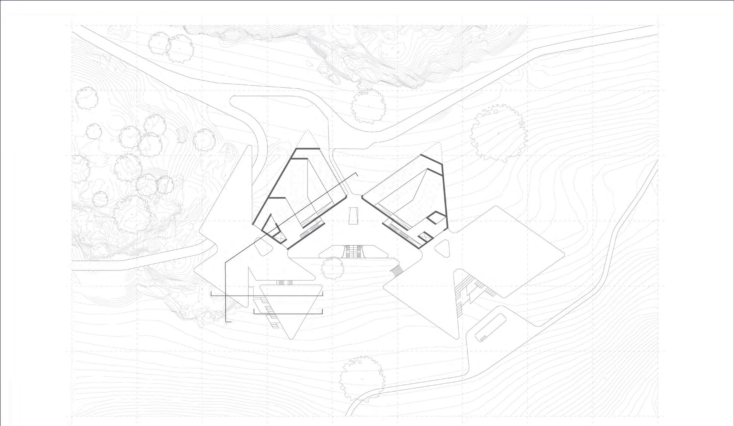
1. Courtyard 2. Atrium/ Hot-desking zone 3. Board room 4. Informal Auditorium 5. External Auditorium 6. External Auditorium Stage 7. Working Module 8. WC A 1 3 2 8 7 7 7 B B A C C


2 8 7 5 4 6 7
Plan Scale 1:500
Ground
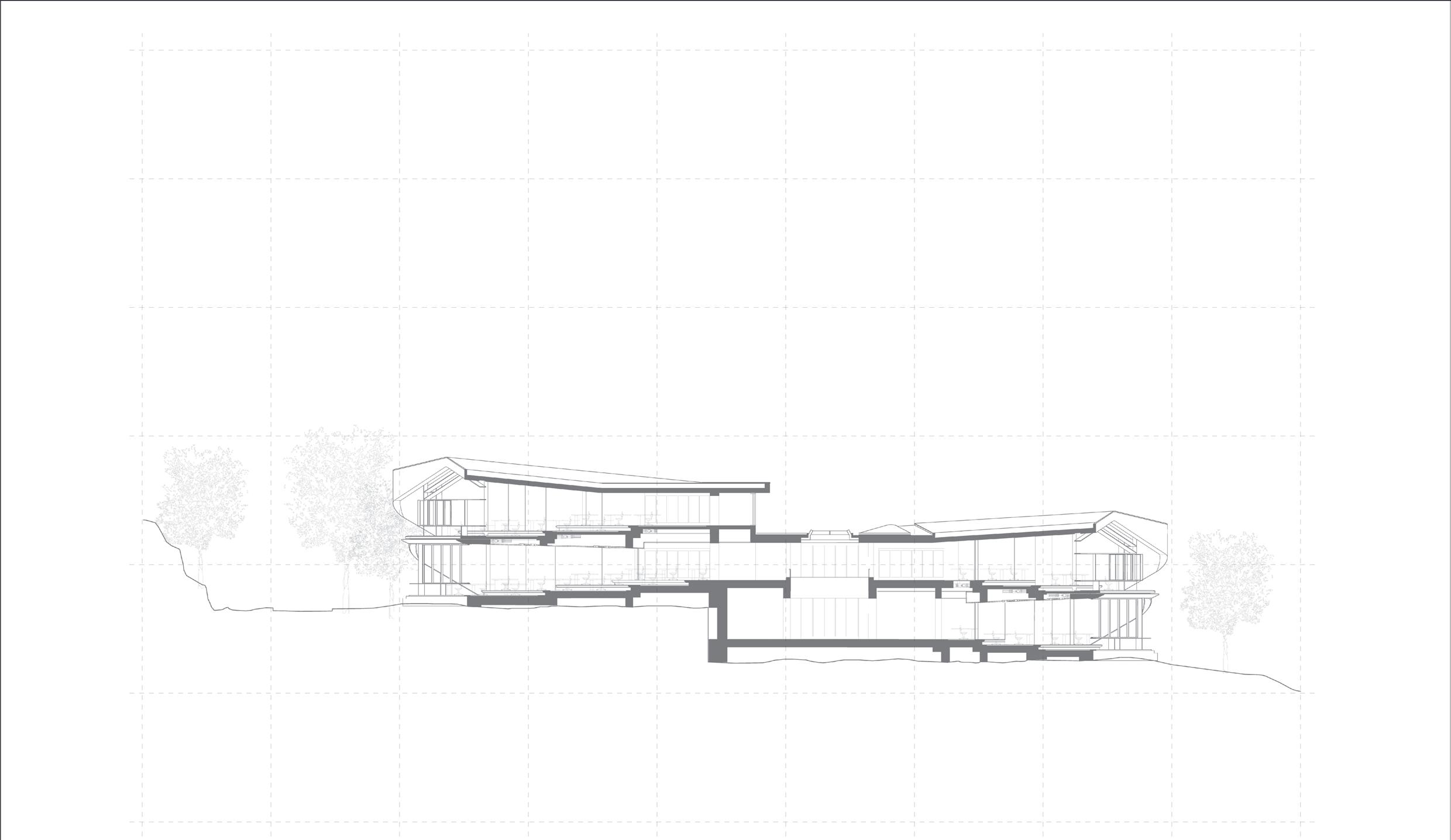
A 2 1 B B A 1.
2. WC C C
Working Module


2 1 First Floor Plan Scale 1:500


A-A
1:750
Section
Scale
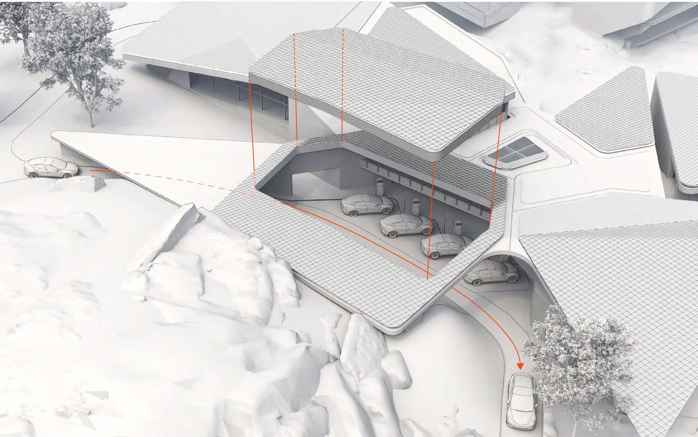 Autonomous Link Dock East to West

Pages: 034-037
Appendix Further Technical Information
Component Composition
Build-up & Further Pre-fabrication
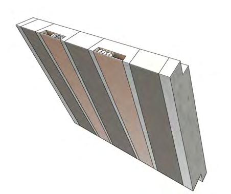
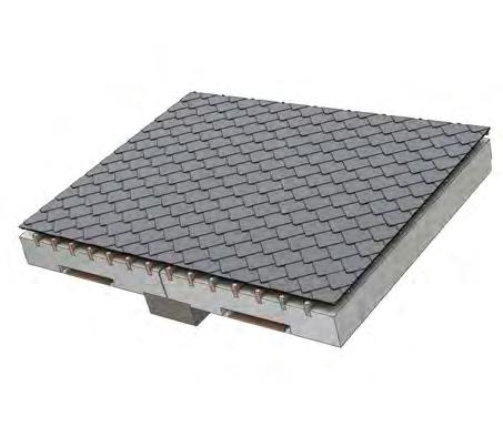
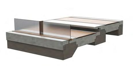
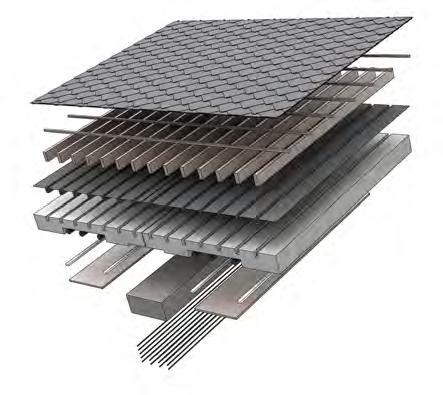
Composed of cascading slabs, each of which are optimised for minimal material usage by, made possible by the complex geometry achievable with CNC EPS foam formwork. Additionally, slab edge detail forms solar shading for the ground floor glazing.
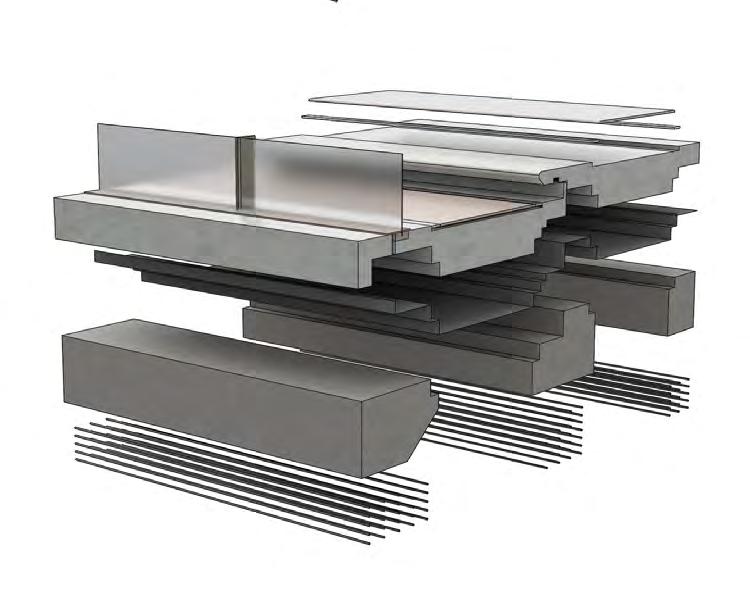
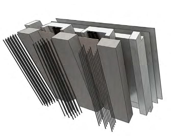
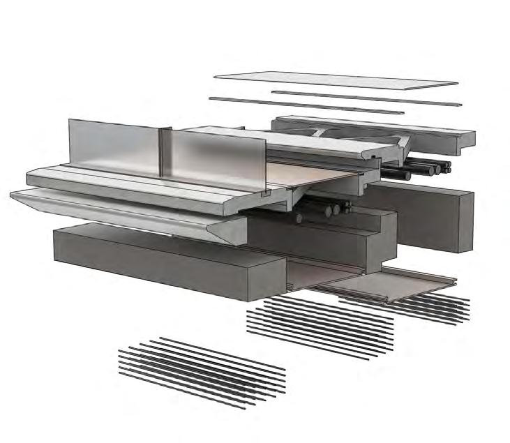
Thermally bias infralightweighht mix sat ontop of compressive mix strip foundations.
Encased structurally bias infralightweight with integrated service zones & pre-applied waterproofing sealant and ceramic glaze forming the final external finish.
“Cast-in” channels receiving rafters to reduce build-up depth & allow the desired slimmer edge profile. Integrated service zone, lighting, & Timber acoustic panel.
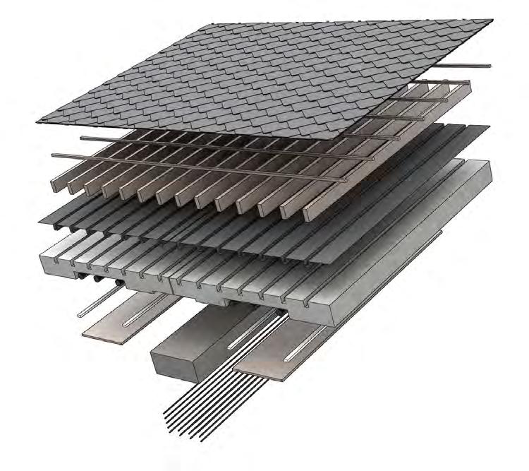
1st Floor composition Supporting Wall composition Roof composition Ground Floor composition Diamond lapped slates Ceramic glaze finish Veneer flooring panel Veneer flooring panel Perimeter vent Perimeter vent Mix 2 Pre-cast concrete component Mix 2 Pre-cast concrete component Steel rebar Mix 2 slab edge detail Timber framed curtain walling system walling component Timber framed curtain walling system walling component Sealant Mix 2 Pre-cast concrete component Timber battens @600mm Centres Timber rafters @400mm Centres DPM & vapour control membrane Mix 2 pre-cast concrete component M&E Services M&E Services Lighting Timber acoustic panel Timber acoustic panel Mix 1 encased structural element Mix 3 in-situ cast foundations Timber acoustic ceiling panel Mix 1 encased structural element Steel re-bar reinforcement Steel re-bar reinforcement Steel re-bar reinforcement Integrated lighting DPM & vapour control membrane Mix 1 encased structural element
2023 Tom Bird
Appendix Advanced Architectural Design
Thermal Performance
Multifunctional Monolithic Ambition
Infralightweight mix variations
Replaces traditional aggregate with exploded clay. Replaces 30% Portland cement with Nano Scilica.
Suited to reinforcement.
High compressive & tensile strength when reinforced. Good thermal performance.
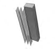
Suited to spanning structure
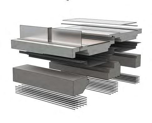
Replaces traditional aggregate with exploded clay. Replaces 65% Portland cement with fly ash geopolymer. Micro aerated & surface skimmed. Very high thermal performance, low density. But compromising compressive strength.
Suited to envelope
Replaces traditional aggregate with foamed glass. 30 % geoplymer binder.
Very hight compressive strength & high thermal performance when unreinforced.
Suited to foundations.
Calculations & target values:
Undertaking speculative U-value calculations. Showing the required thickness of different envelope elements to achieve a U-value which is compliant with UK Approved Document part L. Maintaining a “Concrete only” core to element build-ups for ease of recycling established earlier. U-value data is taken from “worst case” points in the envelope where the insulation mix layers are at their thinnest.
Target U-values for a non-dwelling new build according to Part L:


Pitched Roof: 0.18 W/(m2·K) Wall:0.26 W/(m2·K) Floor 0.18 W/(m2·K)
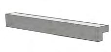
Use Case: Pre-cast vertical & horizontal structure - Substantial reinforcement.
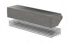
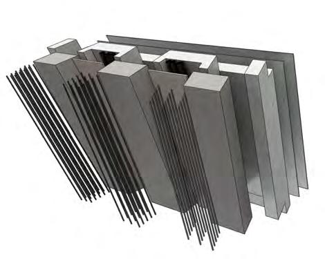
Thermal Conductivity (W/K·m) of raw mix: 0.25
Thermal Conductivity (W/K·m) of dry mix accounting for steel reinforcement as 7% of material volume: 0.38
Use Case: Pre-cast encasing structural elements forming exterior skin, small projection & ornate forms.
Thermal Conductivity (W/K·m) of raw mix: 0.11

Unreinforced
Use Case: In-situ foundations & retaining wall - light to medium reinforcement.
Thermal Conductivity (W/K·m) of raw mix: 0.38
Thermal Conductivity (W/K·m) of dry mix accounting for steel reinforcement as 5% of material volume: 0.40
Geopolymer
mix
Nano Scilica mix
2. Geopolymer mix
Schlaich mix
1.
Nano Scilica mix
Thermal Resistance Compressive Strength Reinforcement Thermal Resistance Roof Build-up: Wall: G Floor: Diamond lapped slates 10mm 2mm 2mm 500mm 650mm Na Na Na Na Na 750mm 5mm 1000mm 1. 1. 2. 575mm 400mm 650mm 400mm 750mm 575mm 2. 2.0 W/K·m 0.75 W/K·m 0.11 W/K·m 0.11 W/K·m 0.11 W/K·m 0.52 W/K·m 0.38 W/K·m 0.38 W/K·m Na Na 5mm 575mm Na Na Na Na 400mm Element: Average Conductivity Best & worst case thermal path: 1. Best case thermal path U=1/ RSI+R1+R2+R3+RsSO RSI = 0.10 RsSO = 0.04 R = Slate (0.01/2) = 0.005 R2 = DPM (0.05/0.75) = 0.067 R3 = Mix 2 (0.575/0.11) = 5.25 R4 = mIx 1 (0.40/0.38) = 1.05 Roof U-Value at thickest points = 0.153 W/(m2·K) 1. Worst case thermal path U=1/ RSI+R1+R2+R3+RsSO RSI = 0.10 RsSO = 0.04 R = Slate (0.01/2) = 0.005 R2 = DPM (0.05/0.75) = 0.067 R3 = MIx 2 (0.575/0.11) = 5.25 Roof U-Value at thinnest points = 0.183 W/(m2·K) 1. Worst case thermal path U=1/ RSI+R1+R2+R3+RsSO RSI = 0.13 RsSO = 0.04 R = Mix 2 (0.4/0.11) = 3.64 R2 = Mix 1 (0.65/0.38) = 1.71 Roof U-Value at thinnest points = 0.182 W/(m2·K) 2. Worst case thermal path U=1/ RSI+R1+R2+R3+RsSO RSI = 0.17 RsSO = 0.04 R = Mix 2 (0.65/0.11) = 5.91 Roof U-Value at thinnest points = 0.163 W/(m2·K) 1. Best case thermal path U=1/ RSI+R1+R2+R3+RsSO RSI = 0.10 RsSO = 0.04 R = Mix 2 (0.75/0.11) = 6.82 Roof U-Value at thinnest points = 0.143 W/(m2·K) 1. Best case thermal path U=1/ RSI+R1+R2+R3+RsSO RSI = 0.17 RsSO = 0.04 R1 = Mix 2 (0.40/0.11) = 3.64 R1 = Mix 3 (1.00/0.40) = 2.50 Roof U-Value at thinnest points = 0.1.57W/(m2·K) Ceramic glaze finish Veneer flooring panel Perimeter vent Mix 2 Pre-cast concrete component Timber framed curtain walling system walling component Sealant Mix 2 Pre-cast concrete component Timber battens @600mm Centres Timber rafters @400mm Centres DPM & vapour control membrane Mix 2 pre-cast concrete component M&E Services Lighting Timber acoustic panel Timber acoustic panel Mix 1 encased structural element Mix 3 in-situ cast foundations Mix 1 encased structural element Steel re-bar reinforcement Steel re-bar reinforcement Steel re-bar reinforcement DPM & vapour control membrane 0.75 W/K·m 1. 2. 1000mm 400mm 650mm 2023 Tom Bird
3. Schlaich mix
Appendix Advanced Architectural Design
Heating & Cooling Strategy
Discreet Active Floor System
Integrated Service Pathways:
Integrated ambient lighting.
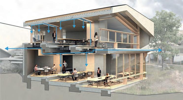
Passive ventilation & MVHR exhaust. On west facing facade, opposing prevailing winds.
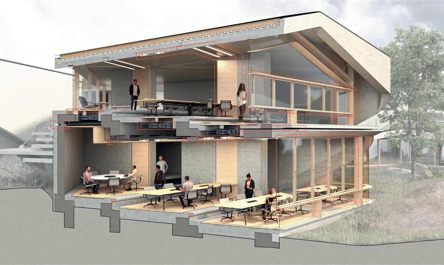
Timber suspended flooring panel. Perforated for power & network services. Easily removed for maintenance.
Integrated Network, plumbing, electrical, & fire suppression survive zone.
Creating a pass through route for trickle ventilation
Service zones inset into concrete of wall and ceiling to provide overhead services to 1st floor work zones.
Trickle ventilation & MVHR intake.
Trickle Ventilation & MVHR: Targeted Heating & Cooling Zones

Operable zones in openings to provide purge ventilation if required.
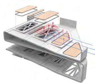
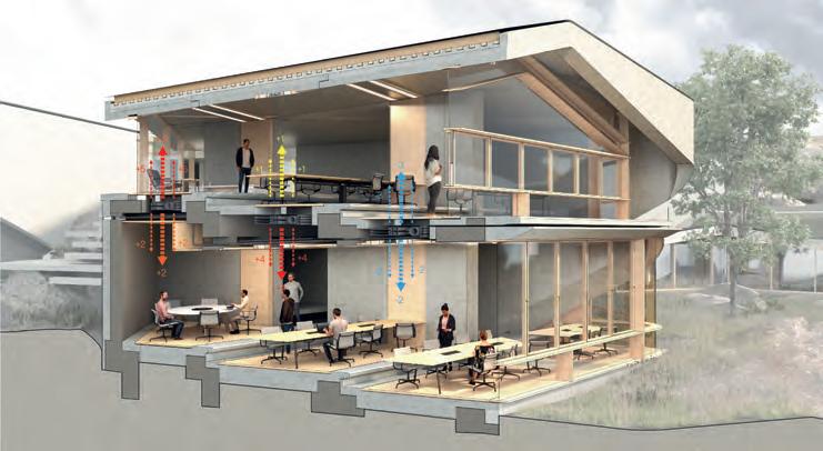
Above: Creating a pass through route for trickle ventilation circulating the pure air of the countryside. Assisted by an MVHR system as not to sacrifice thermal efficiency for increased air change rate.
Routing services the ceiling of each floor to provide top down cooling and heat extraction. Directed towards working zones.
Right:
load
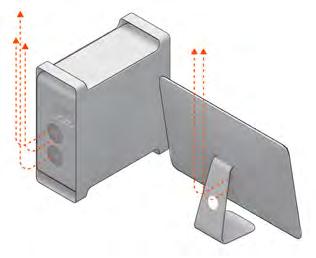
Ensuring optimal working temperature is maintained in all working zones by counteracting specific heat loads emitted in a given zone.
Dedicated heating & cooling control provided to each working zone. Creating the ability to respond to fluctuating temperatures caused by the thermal
of operating computers.
+ °C + °C + °C + °C + °C + °C
MVHR 2023 Tom Bird
Integrated
Appendix Advanced Architectural Design
2023 Tom Bird
Appendix Advanced Architectural Design


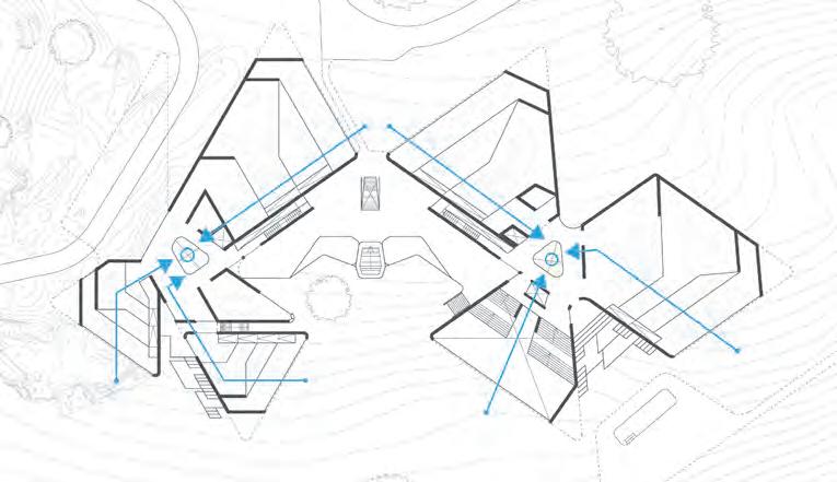
Global Ventilation & Fire Strategy
Airflow Principles
Atrium
Controllable ventilation lovers.
Operable
Surrounding base with integrated rail system.
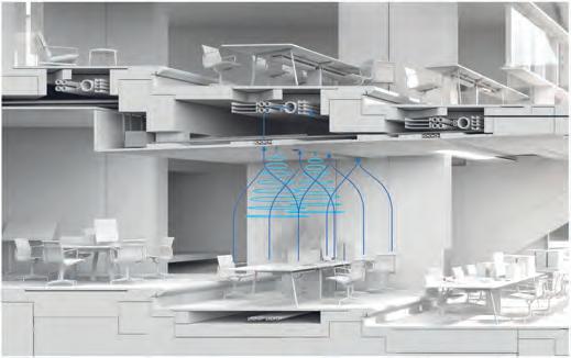
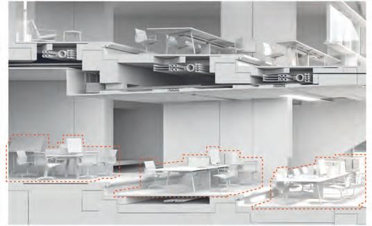
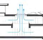
Points of vertical ventilation. Allowing rising warm air out certain -ve pressure & drawing air through ventilation service channels integrated into the floor of working modules.


Response to Fire
Fire suppression system response sequence:
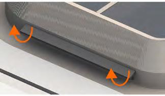
Mode 1: Ventilation lovers open to allow the escape of warm air & utilise high prevailing winds to generate stack effect ventilation. Ultimately passively drawing air through the wider ventilation system.
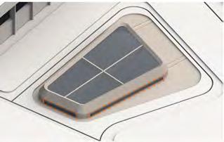
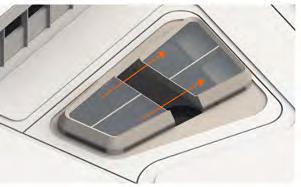
Mode 2: In the event of a fire the skylight may function as an AOV. Partially opening to drastically speed up the rate at which air is drawn through the system. Ultimately drawing smoke through, removing it from circulation zones & allowing users to escape.
Air enters primary system High potential fire load present in working zones Sensor network locates the fire from heat signature & assess severity. Then coordinates a zone-targeted or building wide response Suppression & smoke extraction are applied to affected area only if applicable, preventing unnecessary destruction of equipment & data in wider zones. Residual pressure drives secondary “cross Ventilation” Primary system driven by atrium ventilation Primary system driven by atrium ventilation Residual pressure drives secondary “cross Ventilation” Air enters primary system
driven airflow system:
Integrated service pathways serve working zones with inlets at facade junction. atrium roof-light system:
Two modes of operation:
Smoke extraction through ventilation pathways.
Infralightwight Concrete, Timber, & Slate
All work produced by Unit 14
Unit book design by Charlie Harriswww.bartlett.ucl.ac.uk/architecture
Copyright 2021
The Bartlett School of Architecture, UCL All rights reserved.

No part of this publication may be reproduced or transmited in any form or by any means, electronic or mechanical, including photocopy, recording or any information storage and retreival system without permission in writing from the publisher.

-

@unit14_ucl UNIT
CONSTRUCTED FUTURES 2023


At the center of Unit 14’s academic exploration lies Buckminster Fuller’s ideal of the ‘The Comprehensive Designer’, a master-builder that follows Renaissance principles and a holistic approach. Fuller referred to this ideal of the designer as somebody who is capable of comprehending the ‘integrateable significance’ of specialised findings and is able to realise and coordinate the commonwealth potentials of these discoveries while not disappearing into a career of expertise. Like Fuller, we are opportunists in search of new ideas and their benefits via architectural synthesis.
As such Unit 14 is a test bed for exploration and innovation, examining the role of the architect in an environment of continuous change. We are in search of the new, leveraging technologies, workflows and modes of production seen in disciplines outside our own. We test ideas systematically by means of digital as well as physical drawings, models and prototypes. Our work evolves around technological speculation with a research-driven core, generating momentum through astute synthesis. Our propositions are ultimately made through the design of buildings and through the in-depth consideration of structural formation and tectonic. This, coupled with a strong research ethos, will generate new and unprecedented, one day viable and spectacular proposals. They will be beautiful because of their intelligence - extraordinary findings and the artful integration of those into architecture.
The focus of this year’s work evolves around the concept of ‘Constructed Futures’. The term aims to describe architecture and as such fundamentally human future as the result of the architect’s highest degree of synthesis of underlying principles. Constructional logic, spatial innovation, typological organisation, environmental and structural performance are all negotiated in a highly iterative process driven by intense architectural investigation. Inspiration for inherent principles of organisational intelligence can be observed in both biotic and abiotic systems, in all spatial arrangements where it is critical for the overall performance of the developed order. Through the deep understanding of constructional principles, we will generate highly developed architectural systems of unencountered intensity where spatial organisation arises as a result of sets of mutual interactions. Observation as well as re-examination of civilisatory developments will enable us to project near future scenarios and position ourselves as avant-garde in the process of designing a comprehensive vision for the forthcoming. The projects will take shape as research based imaginative tales, architectural visions driven by speculation.
Thanks to: ALA, DaeWha Kang Design, Foster + Partners, Heatherwick Studio, Populous, RSH+P, Seth Stein Architects, ZHA, Expedition Engineering

UNIT 14 @unit14_ucl All work produced by Unit 14 Unit book design by Charlie Harriswww.bartlett.ucl.ac.uk/architecture Copyright 2021 The Bartlett School of Architecture, UCL All rights reserved.No part of this publication may be reproduced or transmitted in any form or by any means, electronic or mechanical, including photocopy, recording or any information storage and retreival system without permission in writing from the publisher.

 Cover design by Charlie Harris


 MANCHESTER MANCHESTER
SHEFFIELD SHEFFIELD
BUXTON BUXTON


 2. Geopolymer mix


 Ground Work
Phase A
Day 1
Day 2
Day 3
Phase B
Phase C
Phase D
Phase E


 The Peak District Tertiary Assembly
Thomas Bird - Unit 14


 Autonomous Link Dock East to West


