












Boston Dynamics’ Atlas is the most famous humanoid of all time. Atlas has been and will remain a research and development platform designed to push the limits of whole-body mobility for robotics.


Boston Dynamics’ Atlas is the most famous humanoid of all time. Atlas has been and will remain a research and development platform designed to push the limits of whole-body mobility for robotics.
The age of humanoids is just around the corner. Humanoids are a subset of robotics that feature a bipedal (two legs) design, functional arms and “hands,” a torso and a head. It's not necessary for these robots to recreate human hands and fingers, but rather to be able to interact with a world designed for humans.
Humanoids have long been relegated to research labs, but the goalposts recently began to shi . Companies are now creating humanoids to perform various real-world tasks. This means humanoids can operate in environments designed for humans and work alongside humans.
In the short term, basic tasks for humanoids will include picking up and moving items either individually or contained within totes or boxes. Advanced functions will eventually include manipulating door knobs, opening and closing doors and drawers, and using tools designed for humans.
We will be hosting a keynote panel at RoboBusiness 2023 to discuss the state of humanoids. Jeff Cardenas, co-founder and CEO of Apptronik, Jonathan Hurst, co-founder and chief robot o cer of Agility Robotics, and Geordie Rose, co-founder and CEO of Sanctuary, will explore the technological breakthroughs that are propelling humanoids

A detailed look at the challenges and opportunities that exist for the evolving world of humanoids.| Boston Dynamics
into the real world. They'll share their firsthand insights into the challenges and opportunities that lie ahead and discuss the industries poised to be early adopters of these remarkable creations.
Let's look at some of the humanoids that will soon be released and some of the challenges involved with developing these advanced systems.
While humanoids like the Terminator have long entertained us in movies, creating a functional humanoid for the real world remains a difficult task. Power consumption, power-to-weight optimization, mechanical stiffness, edge computing, component reliability and safety are some of the major engineering constraints of the humanoid design.
For decades, roboticists have worked to perfect humanoids, displaying

numerous prototypes and working models. Some researchers have spent their careers perfecting bipedal locomotion or hand design, while others have attempted to program artificial intelligence to give the robots a believable personality that crosses the uncanny valley.
One of the most famous humanoids was Honda's ASIMO, which was first introduced in 2000. Unlike most modern humanoids, with the exception of Boston Dynamics Atlas, ASIMO was a heavyweight weighing in at 130 kgs (286 lbs).
Several technical and engineering breakthroughs have occurred since the days of ASIMO, all of which are enabling lighter-weight designs, longer operating times and faster and more capable edge computing. Advances in battery
chemistry, from the evolution of electric vehicles, provide the right balance of energy density and lower weight that are necessary to deliver longer runtimes for free-ranging humanoids.
Companies have developed edge computing platforms that can process and fuse sensor data onboard the robot while controlling all of its joints in real time. The processing power of a supercomputer can now be delivered in a small, lightweight form factor.
Artificial intelligence and machine learning have evolved so quickly in the last decade that the upcoming generation of humanoids will be able to learn quickly and respond to changes in their environment. This functionality is necessary if this class of robotics is to achieve its goal of being multi-purpose.
For this next generation of humanoids, developers have a highly capable set of technologies to leverage as they push the
boundaries of what’s possible. Let’s take a look at two of the most recognizable humanoids that are currently functional.
Boston Dynamics Atlas is likely the most famous (real) humanoid ever produced. Atlas has been featured in a number of YouTube videos and even a Super Bowl commercial, as it performed a number of dance moves and demonstration moves on parkour courses. These videos have garnered millions of views on YouTube.
For all of its amazing abilities, Atlas remains an R&D project, and there are no plans to commercialize Altas in its current form. In fact, Atlas only operates within the confines of Boston Dynamics' headquarters in Waltham, Mass.
Atlas uses high-pressure hydraulic actuation to move its joints. That would likely have to change before Atlas is suitable for real-world work. Boston Dynamics has leveraged the R&D from Atlas to develop the commerciallyavailable Spot quadruped.
Agility Robotics is currently the only commercially-available humanoid designed for production work and being manufactured in large volumes. The company introduced the fourthgeneration Digit earlier in 2023 and is taking orders for warehousing applications.
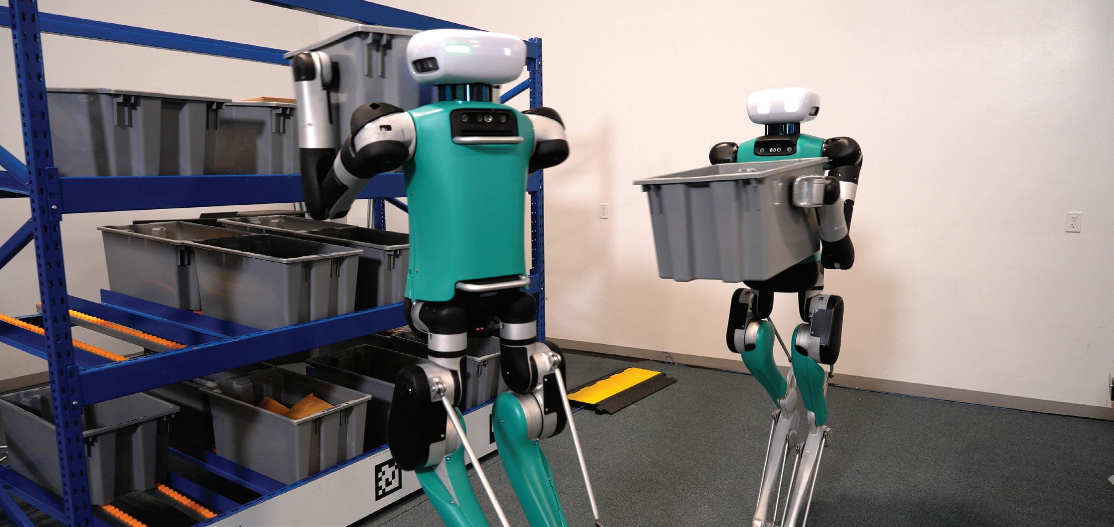
Digit's most unique feature is that its knees bend backward. Its legs are derived from the legs of birds and provide a highly efficient kinematic model that is responsive to unexpected inputs while being energy efficient.
Agility Robotics currently holds the land speed record for a legged robot in part because of this unique design.
The race is on to design and commercialize the next generation of humanoids. Several companies have raised large funding rounds to support these endeavors.
Here is a wishlist of capabilities for this first generation of humanoids:
Physical proportions of an average human: 155-175 cm (61 in - 69 in);
~70 kg (155 lbs)
Minimum 4-hour battery life
Bipedal kinematics
Two arms with functional end-ofarm tooling or hands
AI sufficient to learn from human demonstration and communicate in real-time
Hand and finger design will be a major differentiator for this first generation of humanoid robots. Recreating a mechanical hand with four fingers and an opposable thumb that is analog to the human hand remains a
difficult engineering challenge. Most of the robotics companies we highlight in the next section are designing highlyfunctional hands.
The challenge with hand design is building a hand with the desired flexibility and strength, while still being able to be manufactured at a low cost and be robust enough to survive dayto-day operations in a commercial deployment.
Agility Robotics made a key decision not to implement a high degree of freedom (DOF) hand in Digit, primarily because the robot isn't deployed into use cases where this is a requirement. Digit has a simple yet robust hand design that enables it to pick up and carry fully loaded totes and boxes within a warehouse. A higher DOF hand may be on the future roadmap for Digit once the market demands it.
The primary requirement for a functional humanoid will be to operate effectively within humanbuilt environments. These robots will be deployed into work environments already occupied by humans, and work side by side with human workers. These operating environments will include manufacturing facilities, warehouses, offices, and hospitals. The goal is not to change any of these environments to fit the robots, but rather for the robots to be adaptive to these environments.


The IDT Series is a family of compact actuators with an integrated servo drive with CANopen® communication. They deliver high torque with exceptional accuracy and repeatability, and feature Harmonic Drive® precision strain wave gears combined with a brushless servomotor. Some models are available with a brake and two magnetic absolute encoders with the second providing output position sensing. This revolutionary product line eliminates the need for an external drive and greatly simplifies cabling, yet delivers high-positional accuracy and torsional stiffness with a compact form factor.
• Actuator with Integrated Servo Drive utilizing CANopen®

• 24 or 48 VDC nominal supply voltage
• A single cable with only 4 conductors is needed: CANH, CANL, +VDC, 0VDC


• Zero Backlash Harmonic Drive® Gearing

• Panel Mount Connectors or Pigtail Cables Available with Radial and Axial Options


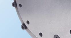

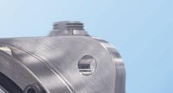


• Control Modes include: Torque, Velocity, and Position Control, CSP, CSV, CST


22 mm diameter, 23 mm depth.
Full multi-turn functionality with maintenance-free rotation counterno backup batteries needed!
17-bit resolution, 32-bit rotation measurement range.
Self-calibration simplifies assembly.
SSI and BiSS C interfacesno license fees.
Find what you need with POSITAL’s online Product Finder. www.posital.com

1X - Neo
1X (formerly Halodi Robotics) has already successfully commercialized its first solution Eve, a wheeled, self-balancing humanoid-like robot. Neo is positioned to be a true humanoid with bipedal legged motion and functional hands.
The company raised an additional $23.5 million in Series A funding in March 2023 that included OpenAI as one of the investors. “1X is at the forefront of augmenting labor through the use of safe, advanced technologies in robotics,” said Brad Lightcap, OpenAI’s COO and manager of the OpenAI Startup Fund. “The OpenAI Startup Fund believes in the approach and impact that 1X can have on the future of work.”
Effectively, 1X is ready to graft the body of Eve to a bipedal leg base for this new generation of robots. The company has already developed autonomous navigation and facility mapping capabilities with Eve. The company has announced that Neo will be released in late 2023.
Sanctuary.AI - Phoenix
Sanctuary.AI is a Canadian company that has demonstrated five generations of its Phoenix robot. The soon-to-be-released sixth generation will be Sanctuary’s first true humanoid with legs and bipedal motion. Prior generations have evolved the torso, arms, and head of the robot.
With the early versions of Phoenix, Sanctuary developed its Carbon AI software. The company has been prolific over the last year publishing a number of YouTube videos that highlight the evolving capabilities of the early generations of Phoenix.
Sanctuary.AI is targeting late 2023 for a release of the bipedal edition of Phoenix. The robot will have a height of 170 cm and weigh 70 kg
Apptronik has developed and delivered several generations of humanoid exoskeletons for the U.S. Department of Defense. From this work, the company developed Astra, its firstgeneration humanoid form factor. Similar to the strategy of Sanctuary.AI, Astra was developed as a torso-only demo unit with functional arms and
hands. Apptronik developed hand-eye coordination for Astra to pick up and manipulate items.
The Austin, Texas-based company is expected to release a completely new humanoid in late summer 2023 called Apollo. There are no pictures of Apollo available yet, but I got a sneak peek of a prototype during a recent visit to Apptronik's headquarters. It has developed all of the kinematics for bipedal motion through its exoskeleton projects.
Apollo will be different from other robots on the market because its joints will be actuated by a novel actuator design. Apptronik expects this novel design feature will help reduce costs, reduce complexity, and eliminate failure points while giving joints and limbs the stiffness and actuation they require.
With the exception of Tesla and Agility Robotics, Figure AI is one of the bestfunded companies in the humanoid race, having raised over $70 million in Series A funding. Our recent podcast conversation with co-founder and CEO Brett Adcock highlighted the progress the company is making toward the first generation of its Figure 01 humanoid.
Founded in 2022, the company has assembled an all-star engineering team with decades of humanoid experience from companies such as Boston Dynamics, Toyota Research Institute, the Institute for Human Machine Cognition, Agility Robotics, Google, and Apple.
Adcock is an experienced startup executive who has successfully launched two prior businesses. He sees humanoid development as a challenging problem, but he has a pragmatic approach to solving the big issues and has assembled all of the elements necessary to deliver a viable solution in this market. Figure AI is also teasing a late 2023 launch of its first product.
In a famous live event, Tesla CEO Elon Musk demonstrated the first walking prototype of its Optimus humanoid. The robot tentatively made its first steps on a stage, and Musk announced this was the first time Optimus walked untethered.


CGI Motion standard products are designed with customization in mind. Our team of experts will work with you on selecting the optimal base product and craft a unique solution to help di erentiate your product or application. So when you think customization, think standard CGI assemblies.


Connect with us today to explore what CGI Motion can do for you. copyright©2021

With this demonstration, Tesla also threw its collective hat into the humanoid race. However, as amazing as it might have been to see Optimus walking on stage, the most amazing thing Musk announced was the $20,000 price. At a time in robotics when most (stationary) collaborative robots cost more than that, this milestone seems unrealistic.
However, one advantage for the Tesla Optimus engineering team is that they have an in-house and captive market for Optimus. The team is working with Tesla's automotive production team to define the use cases for a humanoid. Almost all of the released footage of Optimus shows it operating within a Tesla production facility. Before Optimus is ever released publicly, it will have deployed and iterated on multiple generations within Tesla.
In the months since that first demo, Tesla has continued to release additional videos of Optimus robots performing tasks. Optimus is likely one of the best-funded humanoid development projects, but Tesla has stated it may be 2027 before the product is commercially available.
Xiaomi is one of the largest smartphone manufacturers in Asia, and a public company worth well over $40 billion. The company knows how to design, build, sell, and support consumer electronics. In teasing its CyberOne humanoid, the company generated slick 3D animations of CyberOne, but only one video of real footage of CyberOne onstage with CEO Lei Jun during a launch event.
CyberOne has only been shown with a two-degree of freedom hand/wrist/ finger. This is a much simpler design than companies like Tesla, Figure, Sanctuary, and Apptronik are promising. However, this simplified but robust hand design might be more appropriate for a highend, consumer-style humanoid.
The CyberOne robot is 177 cm and weighs 52 kg, and the list price for the robot has been stated to be $100,000. The company is teasing a 2023 release date for CyberOne, but no more information has been released about the reality of this timeframe.
Fourier Intelligence
GR-1
The Figure 01 humanoid took its first steps in May 2023 –less than one year from the company’s inception.
| FigureShanghaibased Fourier Intelligence has produced exoskeletons since 2017. The company recently unveiled its first-generation humanoid called GR-1. Standing 1.65 meters tall and weighing 55 kilograms, GR-1 has 40 degrees of freedom (actuators) all over its body. With a peak torque of 300NM generated by a joint module installed at the hip, the robot can walk at 5 km per hour and carry objects of 50 kg.

The company designed and developed the Fourier Smart Actuator (FSA) all-in-one actuator series as a high-performance, low-cost actuator. The FSA is core to the design of the company's exoskeletons and now the GR-1.
Fourier is also incorporating AI tools such as ChatGPT into the robot's interaction model to enable more natural interaction with the humans with whom the GR-1 will collaborate. Fourier Intelligence is investigating opportunities to deploy the robot for disaster relief and response, senior care, and household service.
The next 12 months will be an exciting period with at least five companies promising to release their firstgeneration humanoids. The key question is just how functional these new robots will be when they are initially released. But difficult challenges still abound:
Safety will be key: Another hurdle for all of these systems is safety. It's scary to think about what happens when a 70 kg (155 lb) robot fails and collapses to the ground. If one of these robots loses its footing and either tries to compensate to rebalance or falls over, it could injure nearby humans or damage property. We've all seen and laughed at the videos of Boston Dynamics Atlas being bullied by a handler with a hockey stick, but it's no joking matter when these robots are working around the general public and non-professional users.
There is little doubt these systems will be the most complex, autonomous robots ever developed. But a significant commercialization challenge will be to minimize the bill of materials and develop robust and easily maintainable components. Component costs and the overall system price will be key differentiators for these systems.
It's expected that humanoids will eventually be collaborative, working together with humans. The safety features, recovery algorithms, and protocols developed by the various humanoid manufacturers remain important areas of research and development. It will be necessary for all of these vendors to demonstrate that their humanoids are well-behaved and have predictable failure modes before the systems are cleared for deployment.
To help with some of these development challenges, ASTM International recently created a legged robotics subcommittee. The subcommittee will focus on testing and performance standards for legged robots, including humanoids, that operate semiautonomously or in fully automated modes. RR

Understanding the load on a motor will help pinpoint the necessary motor power and required motor accessories.
Searching and selecting a motor for a specific application can often be a challenging task, as there are many potential factors that must be taken into consideration. These include the application’s required voltage, maximum current and diameter, speed, efficiency, and power, among others. Balancing these considerations with other unique application requirements will help ensure the selection of the ideal motor, which is why a collaborative approach between the motion solution and design engineering teams from the outset is vital.
When first approaching a miniature motor supplier for assistance in the

motor selection process, one of the initial questions that must be addressed is the application’s specific working point, or the application's torque and speed. Understanding the load on the motor will help pinpoint the necessary motor power and the required motor accessories. It is also vital to discuss how the motor is integrated into the application, as different types of loads will have a significant impact on a motor’s lifetime and reliability or on the required motor design.
We will explore torque load, radial load, and axial load, which are three different types of loads that are present in common miniature motor
applications. We will also highlight why these loads are crucial to the motor selection process.
Torque is the amount of rotational force generated by a motor during its operation. As the purpose of a motor is typically to convert electrical energy (Pelec = voltage x current) into mechanical energy (Pmech = torque x rotational velocity), torque load is present in almost any application for rotary motors.
Torque load and motor selection
In most cases, simply selecting a motor
based on the required torque value “x” won’t be sufficient. The required torque (and velocity) in an application must be understood over the entire motion cycle, as the motor needs to provide the necessary mechanical power without overheating. This means that you will often be asked by the motion supplier to provide the exact motion cycle that the motor is expected to undergo; this allows for the analysis of the maximum temperature the motor can reach before overheating.
Keep in mind that selecting the right motor requires not only under- standing the required torque value, but also the torque/speed profile over an entire motion cycle and its duty cycle.

In certain applications, the motor or
gearbox must not only provide a certain torque to drive the load, but must also support a radial load, which is a force that is acting radially on the motor shaft. One example of this is a belt drive, which is used to drive an axis parallel to the motor. The tension force must be considered as a radial load acting on the motor shaft, especially if the belt is prestressed.
Radial load is relevant to motor selection due to its impact on bearing options. In the example of a brush DC or stepper motor, there are two standard bearing options: sleeve bearings or ball bearings. Sleeve bearings typically support a lower radial load than ball bearings, as well as provide a lower lifetime; this is offset by their lower cost. Depending on
Selecting the right motor requires not only understanding the required torque value, but also the torque/ speed profile over an entire motion cycle and its duty cycle
the total cost of the motor, using two sleeve bearings instead of ball bearings can decrease the cost of a motor significantly. However, for applications like the belt drive and diaphragm pump where a radial load is present, utilizing at least one ball bearing for the front bearing of the motor helps ensure a reasonable lifetime and is thus a better choice.
In contrast are brushless DC motors, which typically use two ball bearings, as they can be driven at much higher speeds compared to DC or stepper motors. A motor manufacturer will recommend a maximum radial dynamic force at which a minimum lifetime of the motor at a specific speed can be achieved. The maximum radial dynamic force will depend on the size of bearings used, the distance between the two ball bearings in the motor, and the position where the radial load applies. A long motor with oversized ball bearings typically supports a larger radial load than a shorter motor.
There are two types of axial loads: dynamic axial load and static axial load.
If an application requires a 90° rotation of the rotating movement at a lower speed, a worm gear can be an ideal solution. A worm gear consists of a worm shaft that features a spiral thread and is driven by the motor. The worm shaft drives the worm wheel with a reduction ratio as small as roughly 2:1 or larger. Following the spiral thread on the worm shaft, a radial and axial load must be supported by the motor.
Sleeve bearings are not meant for supporting significant axial loads; this means that equipping the motor with ball bearings is often mandatory. Similar to the radial load, the maximum recommended dynamic axial load of a motor will depend on the ball bearings
and preload used, the distance between the two ball bearings in the motor, and the lifetime requirement.
In the example of a typical axial brushless DC motor design, the dynamic axial load is supported by the front ball bearing, as the inner diameter of the bearing is bonded to the motor shaft. In case of an axial push load acting on the motor, the preload on the front ball bearing is reduced; this can lead to additional radial play, negatively impacting the lifetime, vibration, and noise of the motor. In the case of an axial pull load, the load is acting in the same direction as the internal preload, increasing its stress. Motor manufacturers will usually restrict the recommended dynamic axial load to a certain limit that can be supported by a bearing without negatively impacting its lifetime.
Keep in mind that depending on its direction, a dynamic axial load impacts the motor’s bearing assembly differently. In cases of excessive axial loads above the recommended specification, the bearing assembly or the bearings themselves must be improved.
Besides a dynamic axial force acting on the motor during its operation, there’s also a possibility that at least once during the motor’s lifetime, a static axial load will be applied to the shaft. This is usually the case when an additional component (for example, a pinion) is press-fitted onto the motor shaft of the assembled motor. Shock loads, such as when the motor is used in a handheld device and is dropped on the floor, are another example where static axial loads can occur.
In the example of a motor equipped
with ball bearings, the recommended limit for a press-fit operation is typically much higher than for a dynamic axial load. In fact, the limiting factor is only the ball bearings’ elastic limit. As long as the static load applied to the bearing is below its elastic limit, there will be no permanent deformation of the bearing balls or raceway. However, in the same vein, exceeding the maximum recommended load could lead to permanent deformation of the bearing balls and raceway, resulting in reduced life and increased noise and vibration of the bearing.
An additional difference to consider is whether the shaft of the motor can be supported during press-fitting. Certain motors are closed or are equipped with an encoder on the back side, which prevents access to the motor shaft. Without support, the force applied during the press-fit is directly transmitted to the front ball bearing, whose inner raceway is usually bonded to the motor shaft to absorb the axial loads. Supporting the rear shaft allows for a higher force during press-fitting, as the flow of force is going through the motor shaft, not the bearings.
We have reviewed a selection of applications and examples where other forces, in addition to the torque load that is normally present, are acting on a motor. The most common of these are radial and axial loads, which must be taken into consideration in relation to their impact on the motor and how they subsequently influence the selection process of the motor. A dedicated motion solution provider supports customers in correctly capturing the full picture of the loads experienced by the motor in a given application and is therefore fully equipped to develop the most suitable motion solution that fulfills (even exceeds) the application/ device requirements. RR

Machine designers are increasingly asked to build systems that take up less space, operate on less power, and run with higher performance. Thankfully motion controls are answering the call with new motors, new sensors, and new architectures.


It seems that every day there are announcements of smaller and smaller motors, controls, and sensors used in precision motion control. What is driving these applications is the growing demand for motion control components used in surgical, patient treatment, mobile robotics, drones, and battery-powered applications. In this article we will introduce you to recent developments in motion control technology that are letting engineers build systems that use less power, make less noise, and take up less space.


We will look first at the motors themselves to understand how they are evolving and assimilating new sensor and control techniques to boost their performance. Then we will focus on controls to show not just how and why motion control components are physically shrinking, but how new control techniques are being used to maximize motor and system performance.
Finally we will look at how the evolution of motors and controls are impacting architecture. Because it turns out that smaller and more e cient controls allow entirely new approaches to where the controls are located, how they are wired, and how these changes are having a major impact on performance, reliability, and cost.
When comparing various motor types, power output to weight and torque output to weight are two key performance metrics to consider. For a given application, usually one of these two factors are more important than the other, and in fact, they are related because power is defined as torque times spin rate.
Brushless DC motors, with their ability to generate a constant torque up to a high spin rate, typically provide the highest figures of merit for power output to weight. Typical values are double the ratio of DC Brush motors. Step motors, although equently used in portable applications, are not usually part of the power to weight conversation because their torque drops off rapidly as rotation speed increases.

How robotics engineers can build systems that use less power, make less noise, and take up less space.Chuck Lewin | Performance Motion Devices
If we instead want to optimize torque to weight, step motors are back on the table. Traditionally open-loop operated step motors have high holding torques, but their ability to deliver that torque over a working speed range is affected by their tendency to oscillate. Practically speaking, this means the effective torque delivered by the step motor is between 50% and 70% of the motor's rated holding torque.


There is an alternate way of operating a step motor however which largely solves this issue. A technique called closed loop servo, also called stepper servo, uses an encoder to operate the step motor as if it were a two-phase Brushless DC motor. The result is significantly higher torque over the operating range of the motor because mid-range instability, a torque killer for open loop step motors, is eliminated. More on this up and coming technique a bit later in the article.
An interesting aspect of the evolution of motor/actuators is how they utilize (or not utilize) sensors. As motors get smaller and smaller, and as they are implanted or strapped on to patients or used in mobile robots, it becomes harder and harder to add sensors without impacting the motor package size or the robustness of the motor/sensor combination.
So one trend affecting motors is sensorless operation - eliminating sensors and operating the motor using control techniques such as back-EMF (for Brushless DC motors) or electronic stall detection (for step motors).
There are simple and fancy ways to utilize the back-EMF of each winding of a Brushless DC motor. The most straightforward is to measure the backEMF of a floating leg while the other two legs are being driven. The floating leg, no longer influenced by the drive output of the amplifier, contains the back-EMF voltage which can be used to determine the zero-crossing point, allowing a specific location of the commutation cycle to be determined.


Back-EMF works very well under the right circumstances but has so far not been adopted in general purpose motion applications. The first challenge is that back-EMF signals disappear as the velocity of the motor decreases. So, for all practical purposes sensorless Brushless DC applications cannot be used in positioning applications where the motor needs to be controlled around a stationary location.
In a velocity control application, however, sensorless drive has seen significant adoption. Although we still have the problem of not being able to
sense back-EMF signals at low velocity, the controller can overcome this limitation by using a microstepping drive technique (operating the Brushless DC motor as a step motor) to bring it up to speed and then switching to back-EMF commutation once the measured backEMF signal provides su cient signal to noise.
When it comes to step motors, sensorless operation means more or less the opposite. Step motors can position all the way down to zero velocity but need help as the velocity increases, where they are prone to losing steps or having the motion collapse altogether. Sensorless electronic techniques can help by reducing the tendency to oscillate at certain speeds and by detecting that the rotor has stalled.
However the same "it works till it doesn't" limitation that applied for sensorless Brushless DC motors operation applies here as well. It is di cult to guarantee that electronic stall detection will work 100% reliably, so step motor applications that are really mission critical tend to use an encoder to confirm the motion.

Strangely, motors of all types including
very small motors are also trending in the opposite direction, upgrading their sensors to overcome the robustness limitations mentioned earlier, or adding sensors to motor types that previously did not use them.
Upgrading the sensor for robustness o en means moving away om optical sensors, which are otherwise the workhorse of motor position sensing in the form of the quadrature incremental encoders. So to address the needs of harsh environments and medical applications there has been an uptick in the use of non-optical sensing solutions such as magnetic and capacitive encoders.
Magnetic encoders can be hermetically isolated om the motor, measuring the position through a small air gap. The motor's rotor carries a magnetic encoding disk typically mounted at the very end of the motor sha , while the electronic portion of the encoder uses either Hall sensors or magneto resistive sensing techniques to determine the rotor position. Magnetic encoders have leapt forward in resolution since their inception, and now can provide quadrature resolutions of 1,024 counts per rotation or more.
Capacitive encoders can also be hermetically sealed om the motor, and
therefore have seen growing interest for use in harsh environments and medical applications.
Aiding the adoption of these new encoder types are improvements in the controls which use high precision A/ Ds (Analog to Digital converters) and algorithmic techniques to compensate for small irregularities in the encoder's analog output signals along with fast arc-tan calculations to generate resolution-enhanced position values.
Funny, you don't act like a step motor Step motors aren't normally operated with an encoder, but are now going through an evolution which relies on an encoder to operate the motor as a servo motor- essentially spawning the birth of a fourth motor type for positioning motion applications; a er Brushless DC , DC Brush, and traditionally controlled step motors.
We will look at this technique in a bit more depth below, but the characteristics of this "new" motor type are very high acceleration rate, high torque to weight, and a reduction or elimination of the vibration issues found with normal step motors.
This new approach is driving the evolution of the step motor itself. For example, step motors used with the closed loop stepper control mode o en utilize a 3.6 deg per step design rather than the traditional 1.8 deg per step configuration, and the rotors are becoming lighter to allow higher acceleration. Typical applications for the closed loop stepper include coil winding machines, textile equipment, high speed pick and place, die bonding, and others. When the dust settles it seems that we will have two groupings of step motor designs, those designed to be traditionally controlled using full, half, or microstepping techniques without an encoder, and those designed to be controlled as a servo.
There is an interesting footnote to this that makes closed loop stepper particularly impactful for very small step
motors. With traditionally-sized step motors such as NEMA 23 or NEMA 17 it is not all that di cult to machine the rotors and 'matching' stators consistently enough to maintain a consistent step size during motion.
Step motors have a large number of 'teeth' in the rotor, each of which should align precisely with corresponding teeth in the stator for optimum equal-step motion. As the rotor gets smaller and smaller though, the relative impact of small machining inaccuracies has a larger and larger impact on the performance of the motor.

Closed loop step motor operation, because of its ability to smooth over these underlying variations, is becoming an important technique allowing step motors to keep getting smaller and smaller without need for exotic and expensive machining techniques.
Another motor type, the piezo motor, deserves an honorable mention because 'very small' has always been its bread and butter operating domain. Notably, it does not use magnetics to generate torque. Instead it takes advantage of the tiny dimensional change of piezoelectric materials when subjected to an electric field. Utilizing this principle rotary piezo actuators carefully excite the rotor disk to set up a standing wave whose phase can be changed electronically. The stator is effectively a very low-height gearhead that 'grabs' the rotor once the standing wave has been created. When the phase of this standing wave is altered, rotation occurs.
Functionally, piezo motors most resemble step motors. They excel at holding position or moving at relatively low speeds. Like a step motor they do not require an encoder to accomplish this. However, the electronics used to drive piezo motors do not resemble step motors at all, containing very specialized circuitry to generate the standing wave and control its phase.
So far Piezo motors have seen high volume adoption in specific consumer applications such as camera auto-focus


and f-stop control, and modest levels of adoption in niche applications such as ultra-high precision XYZ tables and pointing.
But given their ability to be produced in very small form factors (2 mm x 2 mm x 5 mm or even smaller), and given the larger trends in the medical/robotics world toward smaller motors, it seems a fair bet that we will be seeing more of piezo motors in the future.
The single most important change driving the remarkable size reduction in electronic motion controls are the performance of digital switching amplifiers, most o en MOSFET switches. These ICs, which when first introduced were prone to failure, prone to overheating, and prone to being large, can now switch with 98%+ e ciency, are extremely reliable and have shrunk to remarkable densities.
How can a binary switch command a continuously changing output voltage? While it may seem counter intuitive, modern motion control amplifiers do not literally ampli anything. They 'ampli ' by entirely connecting, or entirely disconnecting (switching) the motor leg to an HV supply voltage or a GND connection.
PWM (Pulse Width Modulation) schemes ensure that an analog command signal can be represented in this digital all on/all off scheme. For example, to present an average of 37.3 volts to a particular motor coil with an HV voltage of 64 volts the PWM output will connect the HV 58.3% of the time (37.3 / 64 = 58.3%), and connect the ground the rest of the time.

One fairly basic area affected by the drive electronics yet still quite important is the PWM drive equency. It may be that the PWM drive equency needs adjusting when changing om a bigger motor drive to a micro-sized motor. Ultimately the
optimal PWM equency is determined by the motor's inductance, but that generally tracks with size. Smaller motors mean lower inductance. A significant source of chatter and heat generation in small motors occurs when there is too much current ripple coming out of the switching amplifier. In the past, a PWM equency of 20 kHz may have been typical, but today PWM equencies of 40 kHz, 80 kHz, or even higher are o en needed to correctly control these motors.
How does PWM equency impact heat generation? The answer is that a digital switching amplifier delivers extraneous energy in a saw tooth pattern for a given current command. Increasing the PWM equency reduces the magnitude of this noise inducing and heat-generating current flow, and improves the accuracy of the current measurement.
Increasing the PWM equency will somewhat decrease your switching amplifier's e ciency, but this is another area that has seen tremendous IC technology progress. MOSFETs in particular have seen big reductions in what are known as 'switching losses' - essentially a fixed loss of energy per switching action. In the past switching losses could eat up 5% or more of the MOSFET's overall e ciency above 40 Khz. With the latest generation of MOSFETs this has dropped dramatically, allowing amplifiers that switch as high as 100 kHz but still operate with 90%+ e ciency.
An interesting new trend related to this is the slow rise in the use of a new switch semiconductor material, Gallium Nitride, o en called GaN for short. Traditional switchers are made om Silicon, but GaN outperforms Silicon at higher equencies when it comes to a reduction of switching losses.
While not yet common for use in motion control amplifiers, improvements in the reliability and manufacturing yields of GaN switches over the last ten years means this type of MOSFET is bound to have a growing impact on small motors and low inductance motors that need to switch at high equencies.
One thermal dagwood sandwich please Beyond improvements in MOSFET and general IC performance there has been a second, less publicized revolution happening in the area of heat flow management.
Driven by the high volume consumer LED lighting market and the challenge of managing the heat that comes om those tiny packages, a new specialized PCB, known as a metal clad printed circuit board (MCPCB) or sometimes called a thermally conductive PCB, is quickly gaining popularity for motion control amplifiers.
This technology stacks a traditional copper PCB which holds the integrated circuits such as MOSFETs, resistors, and

Engineers working at robotic companies all commonly use torque overload protection devices, slip clutches or torque limiters to prevent damage during accidental collisions between robots and other moving machines and keep actuators and speed reduction units safe. A RENCOL® Tolerance Ring can fulfill this need at a fraction of the space and weight of traditional torque limiters.
A RENCOL® Tolerance Ring, which uses spring force and friction as its operating principle, installs coaxially into a drive assembly instead of being installed in series with an assembly. It has wave features which provide a radial force that acts as the spring force to provide friction between components. The peaks of the tolerance ring’s waves embed into the ID of the mating outer housing or gear, and the ID of the tolerance ring acts as the slip surface at the interface with the inner shaft.
The RENCOL® Tolerance Ring fixes two driven components together, transferring torque during normal operation. If a torque threshold is exceeded, the tolerance ring allows the components to slip relative to each other, limiting the torque and protecting the system from damage.
All our RENCOL® Tolerance Rings are custom designed and manufactured for specific customers and can provide torque overload protection ranging from 0.15 Nm to 2100 Nm torque slip thresholds. These are the components that are currently being used in some high-performing robots that are recognized around the world.
Fits coaxially with existing components and eliminates the need for a bulky and heavy subsystem

Designed to slip at the specific torque slip threshold while still fitting your mating hardware dimensions and sizes
Provides repeatable performance over multiple torque slip cycles


The RENCOL® Tolerance Rings guarantee immediate slip for the drive system and eliminate downtime since there is no need to reset anything after a torque slip event.


capacitors onto a relatively thick metal substrate, usually aluminum or copper. The trick to making this sandwich work is the use of a mechanically rigid dielectric layer which e ciently transfers the heat om the copper PCB to the metal layer.
Prior to the development of this heat management technology, manufacturers used a separate step to bond a traditional non heat-conducting PCB to the metal substrate. That approach is more time consuming and not as e cient at transferring heat.
A specific example of how effective such a thermal sandwich can be comes om the PMD laboratory. During one of the many thermal performance tests PMD conducts to certi its amplifier designs, our new N-Series ION Digital Drive, which has a heat sink interface area of about 10 cm2, recorded a temperature drop of only7 deg C om the bottom surface of the abovediagrammed thermal stack to the operating surface of the MOSFET. What makes this remarkable is that these measurements were taken while the amplifier was outputting nearly 2 KWs of power continuously.
Altogether this important new packaging technology has helped accelerate the power density of motion control amplifiers, allowing newer generations of motor and actuator amplifiers to achieve drive output densities of 100W per cc3 and higher.
Why can't I y an egg on this motor?
To finish up our discussion of advancements in motion controllers that impact small motor operation, we will look at two control techniques, one for Brushless DC motors and one for step motors that improve e ciency, and therefore reduce heat generation in the motor. For motors that may be implanted in the patient are operated by hand, cool operation is vital.
The first technique to improve e ciency we will look at is FOC (Field Oriented Control) and its close cousin sinusoidal commutation. Both of these techniques apply to Brushless DC motor control and allow these motors to operate more e ciently with more of the commanded voltage creating usable torque.
The traditional approach toward commutating Brushless DC motors is called trapezoidal or six-step commutation. This method relies on Hall sensors which provide a new commutation vector every 60 degrees, which corresponds to six discrete locations per electrical cycle.
In an ideal world, however, the commutation vector would be kept exactly 90 deg om the rotor's N-S (north south) vector at all times. The fact that instead, Hall-based controllers receive a new update only every 60 degrees, means the drive vector will be off by up to 30 degrees, and therefore ine cient. The effective torque output of the motor is reduced in

a cyclic pattern by up to 13%. Averaged over a complete rotation the average loss of e ciency is 5%.
Bring on the closed loop stepper
The second control technique we will spotlight applies to step motors. This new type of control technique is called closed loop stepper, also sometimes called stepper servo. What makes closed loop stepper powerful is that it can use a standard step motor yet extract more effective torque out of it, particularly over the full range of operating speeds. How does closed loop stepper work? Closed loop step motor operation is different in three key ways om traditional open loop step motor operation. The first is that it requires an encoder to be attached to the step motor, one with a fairly high resolution. For standard 1.8 degree step motors you will want an encoder with no less than 2,500 counts per mechanical rotation.
The second difference is that closed loop stepper operates the motor like a two-phase Brushless DC motor and commutates the phase angle using the actual encoder position. The third difference is that rather than being constant, the height and sign of the current waveform are continuously adjusted based on the output of a position PID (Proportional, Integral, Derivative) loop.
This means closed loop stepper drives the step motor with just enough power to get the job done. Open loop step systems must drive the motor at a power level to handle the worst-case profile and load scenario. The result is that closed loop stepper can drive the motor with much less heat generated.
Small step motors benefit particularly om the closed loop stepper control method. Since the encoder determines the position, small variations in the teeth spacing which would otherwise result in bumps and wiggles of the motion, are handled ‘invisibly’ by the servo, which increases or decreases the applied torque to compensate.

This is similar to the experience that many users have had with regular DC Brush or Brushless DC motors. A welltuned servo can do a remarkable job of masking small problems with the motor bearing, the gear head, and even the load itself. This is in fact the basis of most machine monitoring observers, and the related art and science of machine failure prediction.
By looking at how the PID’s servo error and servo error integral buildup change over time, a lot can be learned about the health of the downstream mechanical components, even if the motor is staying within its servo accuracy target spec and functioning acceptably. Machine failure prediction is a fascinating subject area which is receiving more and more attention and which we will look at in a future article.
Let’s look at two approaches to achieving a motion controller function. In one, motors and sensors are located at the target machine while the motion controller and amplifier are located remotely, perhaps in a rack, or perhaps in the form of a motion control board mounted in an industrial computer
The second shows everything hosted locally - the motor, the sensors, and the entire motion controller. When hosted locally, the motion controller can take the form of cable connected modules, an application specific control board built from PCB-mounted modules, or an application specific control board built from an assemblage of ICs.
As it turns out, just as 'smaller is better' for an increasing number of applications when it comes to the motor and amplifier size, 'closer is better' when building machines that use motion control particularly those that integrate analog sensors such as sin/cos encoders.
The reason boils down to two simple principles: shorter signal runs mean cleaner more accurate signals, and shorter signal runs means the servo loop can run faster while still maintaining safe
phase margins. Both of these factors have a major impact on motion performance, but in particular on positioning accuracy. While some machine applications will not see big performance improvements from shorter signal runs, systems with smaller motors, and systems utilizing newer generations of encoders such as sin/cos encoders striving for ultrahigh accuracy measured in nanometers or even picometers will. Similarly, for spindles that need to maintain high position or velocity control accuracy, fast servo loops and clean sensor signals can make a big difference.
The above principle of 'closer is better' explains a slow but distinct trend toward embedded motion control solutions versus remotely mounted solutions. This trend is most noticeable for smaller machines, but can be observed even for larger machines such as those commonly used with semiconductor capital equipment, laboratory equipment, and packaging equipment.
While there may not be a big motion performance gain with embedded control in these 'bigger' applications, a single PCB-based embedded motion solution located right at the machine makes the final solution more compact relative to a machine with a control setup that uses cable bundles emerging from the machine connecting to a remote mounted control rack or industrial computer.
Cost-wise, embedded control can be cheaper than module or board based control but this is volume dependent. If the local PCB is designed at the IC level the upfront design effort is usually greater, but if there is enough volume this will be amortized over the larger number of machines and the per system cost may well be lower.
There is a new motion control device however that is easing the barrier to building application specific embedded control boards. Known variously as an intelligent amplifier, programmable
amplifier, or motion control module, these PCB-mountable devices greatly simplify the task of creating a custom control board.
This is because these devices do all the heavy lifting associated with the machine control function. They can run user application code, generate motion profiles, handle servo positioning, and drive the motor with an on-board amplifier. These devices also offer multiple interfaces, typically serial, CAN, and Ethernet. Most importantly they are small, often measuring just 3-5 cms on a side.
For the design engineer building an application specific motion control board using these plug-andplay devices, the task is more one of interconnecting then of actual circuit design. Whereas a full blown motion board designed from ICs would typically require a 10+ layer PCB and serious digital and analog design skills, a board made with these plug-and-play motion control modules is typically a 2 or at most 4 layer board, and the design task focuses on selecting connectors and specifying the board's form factor.
While not new, PCB-mounted motion control modules have shrunk dramatically in size and increased dramatically in power output over the last ten years. They are very much a product of the type of electronic advancements discussed earlier. Owing to their tremendous convenience we can safely say that these devices are here to stay and will continue to shrink in size and expand in capability in the future. RR

• Adjustable handles and knobs replace standard hardware and can be used to torque components without tools.

• Levers can be used with Ruland shaft collars for quick installation and adjustment.

All products available directly on RULAND.COM
• Beam couplings accommodate light weights and high misalignment.
• Zero-backlash jaw couplings for vibration dampening and a variety of performance options.


• Bellows couplings for high size to torque ratio.

Ruland Manufacturing is proud to support the FIRST Robotics Competition as a Gold Supplier of precision shaft collars & couplings.
• Thousands of size and style options.
• Proprietary manufacturing processes ensure superior fit and finish.
• 8 material options.
• Rubber bumpers are ideal as end stops or mounting feet.
• Vibration isolation mounts can be sandwiched between components to dampen shock loads.

• Both types can have studs or tapped holes.
• Assorted components allow you to build small assemblies for mounting sensors, conveyor rails, machine guards, and more.
• Optional pre-designed kits make it easier to select the right system for your application.
• No tools required to install, remove, and adjust.
• Best suited for systems that require frequent adjustments.


Today’s increasing demands of automation and robotics in various industries, engineers are challenged to design unique and innovative machines to differentiate from their competitors. Within motion control systems, flexible integration, space saving, and light weight are the key requirements to design a successful mechanism.
Canon’s new high torque density, compact and lightweight DC brushless servo motors are superior to enhance innovative design. Our custom capabilities engage optimizing your next innovative designs.


We are committed in proving technological advantages for your success.
At CGI we serve a wide array of industries including medical, robotics, aerospace, defense, semiconductor, industrial automation, motion control, and many others. Our core business is manufacturing precision motion control solutions.
CGI’s diverse customer base and wide range of applications have earned us a reputation for quality, reliability, and flexibility. One of the distinct competitive advantages we are able to provide our customers is an engineering team that is knowledgeable and easy to work with. CGI is certified to ISO9001 and ISO13485 quality management systems. In addition, we are FDA and AS9100 compliant. Our unique quality control environment is weaved into the fabric of our manufacturing facility. We work daily with customers who demand both precision and rapid turnarounds.
Canon U.S.A., Inc Motion Control Products 3300 North First Street San Jose, CA, 95134
408-468-2320
www.usa.canon.com
CGI Inc.
3400 Arrowhead Drive Carson City, NV 89706
Toll Free: 1.800.568.4327
Ph: 1.775.882.3422
Fx: 1.775.882.9599
WWW.CGIMOTION.COM
The SHA-IDT Series is a family of compact actuators that deliver high torque with exceptional accuracy and repeatability. These hollow shaft servo actuators feature Harmonic Drive® precision strain wave gears combined with a brushless servomotor, a brake, two magnetic absolute encoders and an integrated servo drive with CANopen® communication. This revolutionary product eliminates the need for an external drive and greatly simplifies cabling yet delivers high-positional accuracy and torsional stiffness in a compact housing.
www.Harmonicdrive.net
https://www.harmonicdrive.net/products/rotary-actuators/integrated-actuators/sha-integrat ed-with-servo-drive

Here at Lin Engineering, we find solutions to your problems by focusing on three basic elements: Find, Optimize, and Integrate. There are such a vast number of products on the market that just narrowing the options can be difficult. Our engineers will help you find the motor you need. The motor may then be optimized for your application by changing the winding, magnets, bearings, and more. We work with your team throughout this process to configure the motor to your application so it can be seamlessly integrated within your product or assembly.


Contact info: Lin Engineering 16245 Vineyard Blvd. Morgan Hill, CA 95037
https://www.linengineering.com/ 1.408.919.0200
Advancing innovation for over 100 years

Why accept a standard product for your custom application?
NEWT is committed to being the premier manufacturer of choice for customers requiring specialty wire, cable and extruded tubing to meet existing and emerging worldwide markets. Our custom products and solutions are not only engineered to the exacting specifications of our customers, but designed to perform under the harsh conditions of today’s advanced manufacturing processes. Cables we specialize in are LITZ, multi-conductor cables, hybrid configurations, coaxial, twin axial, miniature and micro-miniature coaxial cables, ultra flexible, high flex life, low/high temperature cables, braids, and a variety of proprietary cable designs. Contact us today and let us help you dream beyond today’s technology and achieve the impossible.

A new generation of IXARC encoders is now available, with new sensor technology and upgraded processors for better performance and reduced energy consumption. Incremental encoders are programmable, with performance and communications interface characteristics that can be customized to meet your particular application. Multiturn absolute encoders feature upgraded self-powered rotation counters – no batteries required! With a wide range of mounting and connectivity options available, IXARC encoders can easily replace encoders from most major manufacturers.
More NeXtGen products are on the way, including kit encoders for direct integration with motors and drives. Stay tuned for new announcements!

Ruland Manufacturing offers a variety of zero-backlash servo couplings designed for use in high precision applications like automation and robotics. Ruland offers beam, bellows, disc, oldham, jaw, and newly-released Controlflex couplings in thousands of off-the-shelf combinations and sizes to help designers optimize their systems.

Robotic vision systems, material handling robots, and automated guided vehicles have infamously strict requirements that require engineers to balance torque, weight, dampening, and more, all while retaining extremely precise power transmission. Ruland servo couplings excel in demanding applications and can be selected based on a wide variety of performance characteristics.
Visit Ruland.com for access to everything you need to make a coupling design decision including: full technical product data, 3D CAD models, installation videos, and eCommerce to make prototyping easy.
The THK micro-size Cross-Roller Ring RAU features a 10mm inner diameter and a 21mm outer diameter. It is more compact, lightweight and rigid than a double row angular contact ball bearing type. RAU rollers travel on V-shaped raceways ground into the inner and outer rings. Alternating rollers are arrayed orthogonally so that one bearing can support loads and moments in any direction. Spacer retainers enable smooth movement and high rotation accuracy.

Ruland Manufacturing
6 Hayes Memorial Dr. Marlborough, MA 01752
508-485-1000
www.ruland.com
email: sales@ruland.com
https://www.thkstore.com/products/rotation/cross-roller-rings/rau.html
THK America, Inc. 200 East Commerce Drive Schaumburg, IL 60173
Phone: 847-310-1111
www.THK.com