PhD Thesis by Yu-Hsuan Juan

Page 20

Chapter 1

6

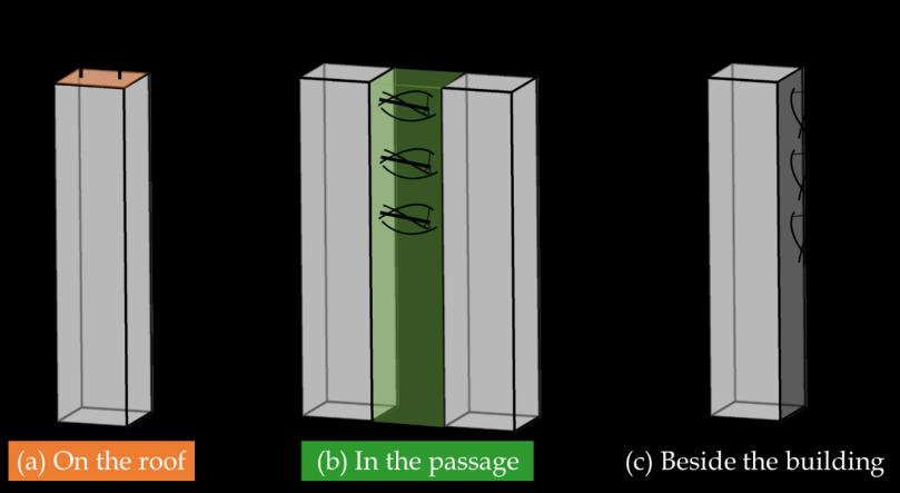
Figure 1.1. Potential regions of incorporating wind turbines into buildings

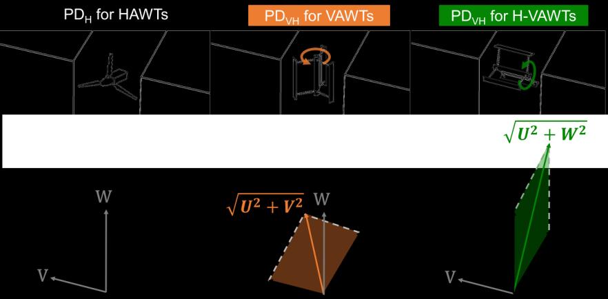
Concerning the type of wind turbine, the vertical axis wind turbine (VAWT) and the horizontal axis wind turbine (HAWT) are the two most well-known types. Many studies emphasized that the VAWT is highly advantageous over the HAWT primarily due to its potential power gain in vertically skewed airflows and omni-directionality [19-21]. To further evaluate the wind energy potential considering other turbine types, three different combinations of wind turbine type and orientation are illustrated in Fig. 1.2. Note that the relative velocity component for each turbine type is different as indicated. a)

b)

c)

The typical HAWT: the HAWT is positioned with its axis in the horizontal direction. The corresponding power density is calculated using the mean streamwise velocity component (U), as the normal component to the rotor plane. The typical VAWT: the VAWT is positioned with its axis in the vertical direction. The corresponding power density is calculated using the vector sum of the streamwise and lateral velocity components ( U 2 + V 2 ). The horizontally-mounted VAWT: the VAWT is positioned with its axis in the horizontal direction. The corresponding power density is calculated using the vector sum of the streamwise and vertical velocity components ( U 2 + W 2 ).

Due to the different relative velocity components for each turbine type and its orientation, the power density can be different for different turbines at diverse possible installation regions. Therefore, a detailed investigation is required to provide insight into the impacts of the wind turbine type and orientation on the wind power density and acceptable turbulence intensity.

Figure 1.2. Schematic of wind turbine type and orientation.


Turn static files into dynamic content formats.

Create a flipbook

Articles inside

References

29min
pages 151-164

Biography

1min
pages 165-166

4.5 Discussion

3min
pages 105-106

4.4.2 Impact of building corner shape

8min
pages 97-103

5.1 Introduction

13min
pages 112-116

5 Urban wind energy potential for a realistic high-rise urban area

1min
page 111

4.4.1 Impact of urban density

9min
pages 91-96

4.3.3 Computational settings

1min
page 89

4.3.2 Computational domain and grid

2min
page 88

4.2.1 Turbulence model sensitivity analysis

1min
page 85

4.2 CFD validation study

2min
pages 83-84

4 Urban wind energy potential: Impacts of urban density and layout

1min
page 79

3.5.5 Impact of wind direction

1min
page 76

4.1 Introduction

8min
pages 80-82

3.5.4 Impact of wind turbine type and orientation

3min
pages 73-75

3.5.3 Impact of corner radius

2min
pages 71-72

3 Urban wind energy potential: Impacts of building corner modifications

1min
page 53

3.5.2 Impact of chamfer length

2min
page 70

3.4.3 Grid-sensitivity analysis

1min
pages 62-63

2.7 Conclusions

3min
page 52

3.2.2 CFD validation: computational settings and results

3min
pages 58-59

3.3 Test cases

1min
page 60

2.6 Limitations of the study

1min
page 51

Discussion ...................................................................................................................................... 131

1min
page 20

buildings (d

12min
pages 42-50

Summary and Conclusions.......................................................................................................... 133

1min
page 21

Summary

2min
page 15

1.4 Thesis outline

3min
pages 23-24

2.2.2 CFD validation: computational domain and grid

1min
page 30

2.2.3 CFD validation: other computational settings

2min
pages 31-32

2 Urban wind energy potential: Impact of building arrangement and height

1min
page 25
Issuu converts static files into: digital portfolios, online yearbooks, online catalogs, digital photo albums and more. Sign up and create your flipbook.