PhD Thesis by Yu-Hsuan Juan

Page 31

Urban wind energy potential: Impact of building arrangement and height

17

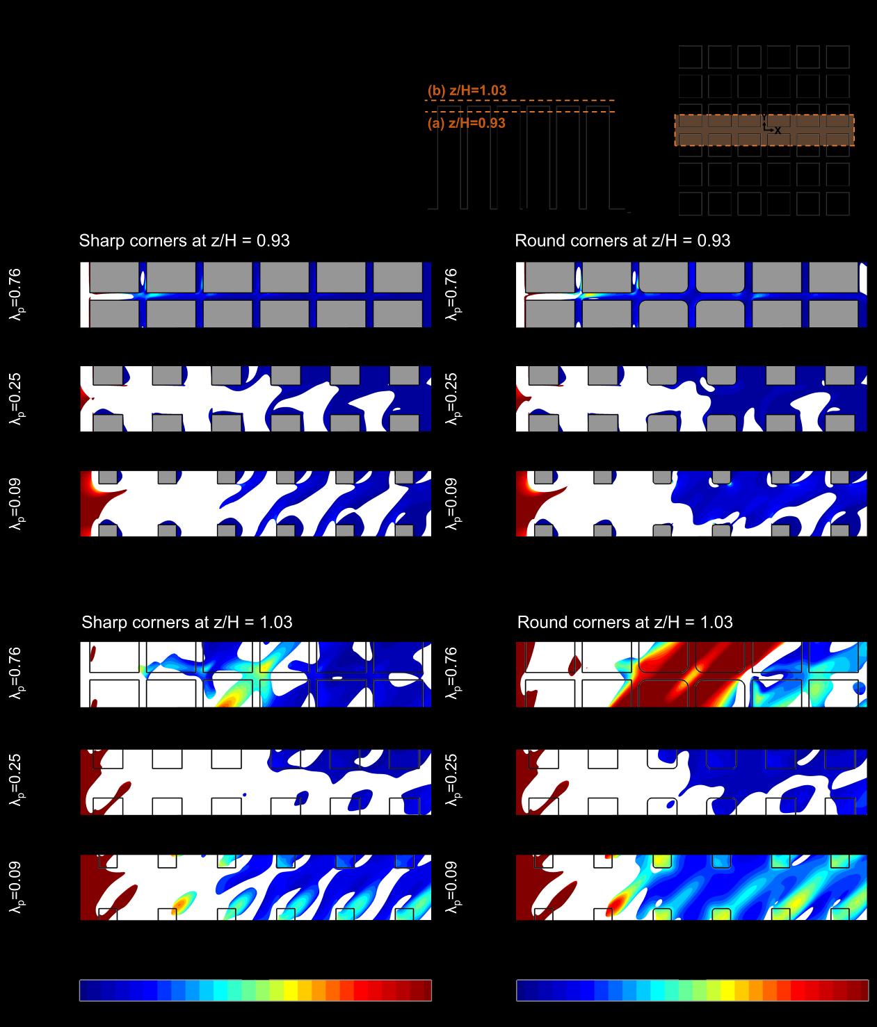
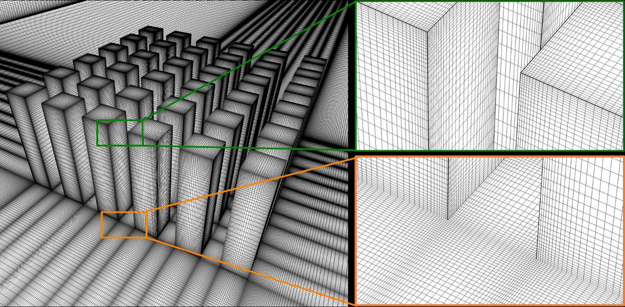
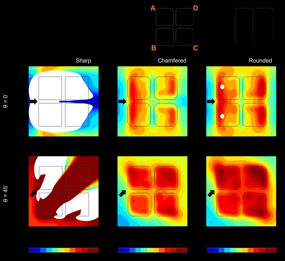
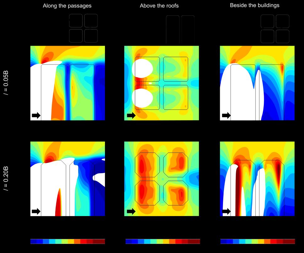
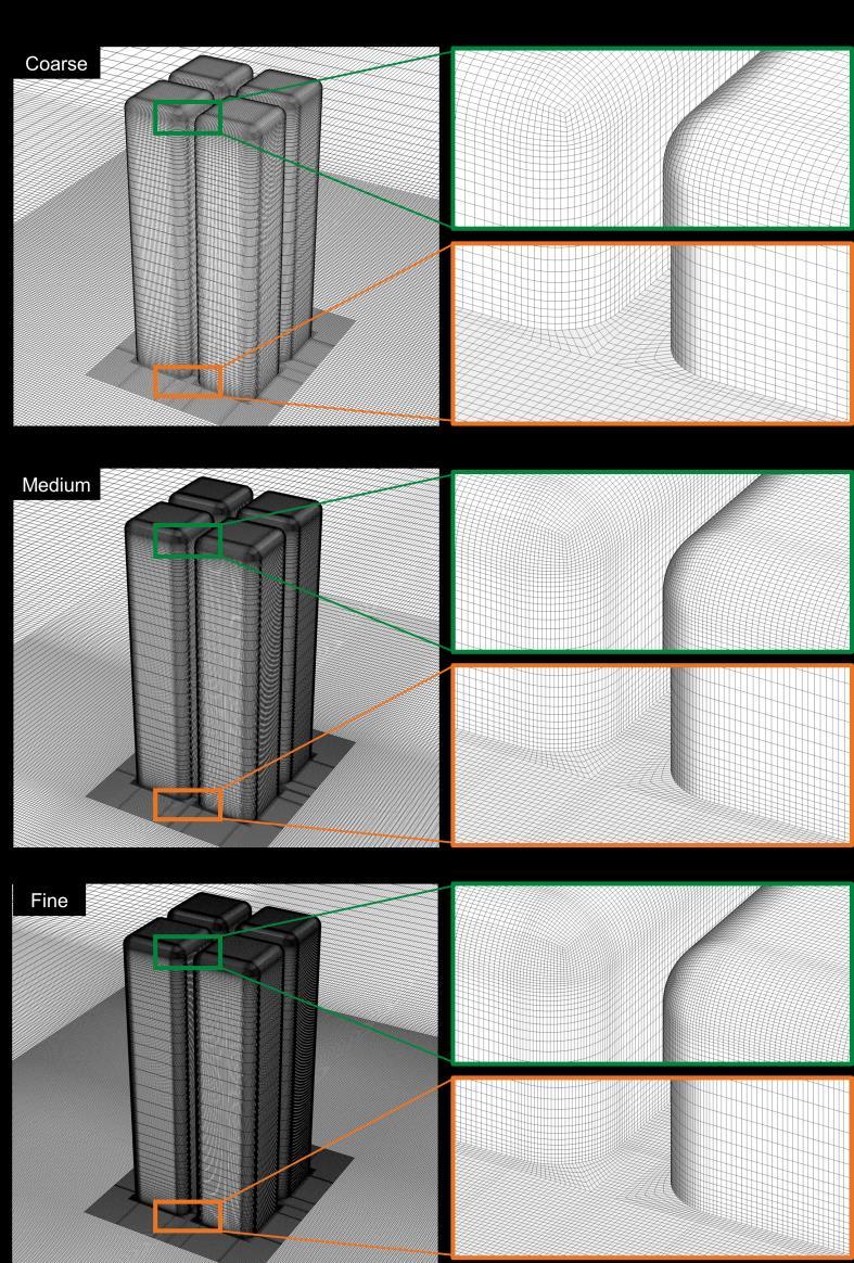
length is 3H, which is smaller than that proposed by the best practice guidelines, to limit unintended streamwise gradients in the vertical inlet profiles [87, 88]. The computational grid consists of 5,464,450 hexahedral cells, see Fig. 2.2b, with 20 cells in the passage between the buildings. The maximum and average y* values are 76 and 40, respectively. This ensures that the center points of wall-adjacent cells are located in the logarithmic layer of the boundary layer, thus the standard wall functions can be employed for the near-wall treatment. The grid resolution is based on a grid-sensitivity analysis presented in Section 2.2.4. 2.2.3

CFD validation: other computational settings

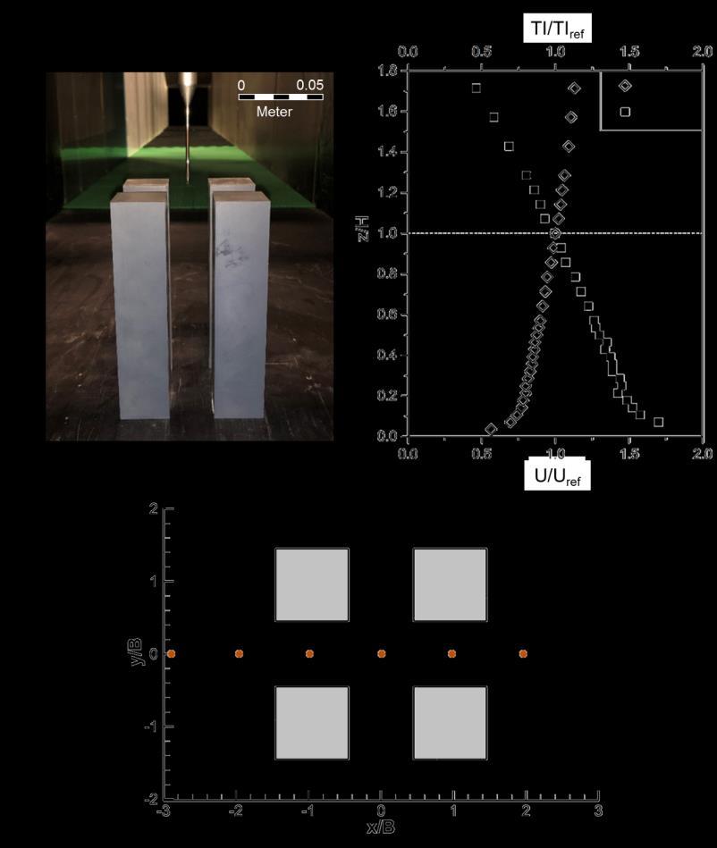
The profiles of the mean wind speed, turbulent kinetic energy and turbulence dissipation rate at the domain inlet are specified using the measured incident vertical profiles of the mean velocity and turbulence intensity, shown in Fig. 2.1b. The turbulent kinetic energy k is calculated from U(z) and TI (z) using Eq. 2.1, where a is 1.5. The turbulence dissipation rate ɛ is given by Eq. 2.2, with κ, u*ABL and z0 representing the von Karman constant (= 0.42), the ABL friction velocity (= 0.55 m/s), and the aerodynamic roughness length (= 9×10⁻⁶ m). 2

𝑘(𝑧) = 𝑎(𝑇𝐼(𝑧)𝑢(𝑧)) 𝑢∗

3

𝐴𝐵𝐿 𝜀(𝑧) = 𝜅(𝑧+𝑧

0)

(2.1) (2.2)

Figure 2.2. Perspective view of (a) computational domain and (b) computational grid at surfaces of the building models and part of the ground surface (5,464,450 cells).


Turn static files into dynamic content formats.

Create a flipbook

Articles inside

References

29min
pages 151-164

Biography

1min
pages 165-166

4.5 Discussion

3min
pages 105-106

4.4.2 Impact of building corner shape

8min
pages 97-103

5.1 Introduction

13min
pages 112-116

5 Urban wind energy potential for a realistic high-rise urban area

1min
page 111

4.4.1 Impact of urban density

9min
pages 91-96

4.3.3 Computational settings

1min
page 89

4.3.2 Computational domain and grid

2min
page 88

4.2.1 Turbulence model sensitivity analysis

1min
page 85

4.2 CFD validation study

2min
pages 83-84

4 Urban wind energy potential: Impacts of urban density and layout

1min
page 79

3.5.5 Impact of wind direction

1min
page 76

4.1 Introduction

8min
pages 80-82

3.5.4 Impact of wind turbine type and orientation

3min
pages 73-75

3.5.3 Impact of corner radius

2min
pages 71-72

3 Urban wind energy potential: Impacts of building corner modifications

1min
page 53

3.5.2 Impact of chamfer length

2min
page 70

3.4.3 Grid-sensitivity analysis

1min
pages 62-63

2.7 Conclusions

3min
page 52

3.2.2 CFD validation: computational settings and results

3min
pages 58-59

3.3 Test cases

1min
page 60

2.6 Limitations of the study

1min
page 51

Discussion ...................................................................................................................................... 131

1min
page 20

buildings (d

12min
pages 42-50

Summary and Conclusions.......................................................................................................... 133

1min
page 21

Summary

2min
page 15

1.4 Thesis outline

3min
pages 23-24

2.2.2 CFD validation: computational domain and grid

1min
page 30

2.2.3 CFD validation: other computational settings

2min
pages 31-32

2 Urban wind energy potential: Impact of building arrangement and height

1min
page 25
Issuu converts static files into: digital portfolios, online yearbooks, online catalogs, digital photo albums and more. Sign up and create your flipbook.