Italiana
International Journal of the Italian Association for Metallurgy
n.02 febbraio 2023
Organo ufficiale dell’Associazione Italiana di Metallurgia.
Rivista fondata nel 1909
La Metallurgia Italiana
International Journal of the Italian Association for Metallurgy
Organo ufficiale dell’Associazione Italiana di Metallurgia. HouseorganofAIMItalianAssociationforMetallurgy. Rivista fondata nel 1909
Direttore responsabile/Chiefeditor: Mario Cusolito
Direttore vicario/Deputydirector: Gianangelo Camona
Comitato scientifico/Editorialpanel:
Marco Actis Grande, Silvia Barella, Paola Bassani, Christian Bernhard, Massimiliano Bestetti, Wolfgang Bleck, Franco Bonollo, Irene Calliari, Mariano Enrique Castrodeza, Emanuela Cerri, Vlatislav Deev, Andrea Di Schino, Donato Firrao, Bernd Kleimt, Carlo Mapelli, Denis Jean Mithieux, Roberto Montanari, Marco Ormellese, Mariapia Pedeferri, Massimo Pellizzari, Barbara Previtali, Evgeny S. Prusov, Dario Ripamonti, Dieter Senk
Segreteria di redazione/Editorialsecretary: Marta Verderi
Comitato di redazione/Editorialcommittee: Federica Bassani, Gianangelo Camona, Mario Cusolito, Carlo Mapelli, Federico Mazzolari, Marta Verderi, Silvano Panza
Direzione e redazione/Editorialandexecutiveoffice: AIM - Via F. Turati 8 - 20121 Milano tel. 02 76 02 11 32 - fax 02 76 02 05 51 met@aimnet.it - www.aimnet.it
Reg. Trib. Milano n. 499 del 18/9/1948. Sped. in abb. Post. - D.L.353/2003 (conv. L. 27/02/2004 n. 46) art. 1, comma 1, DCB UD
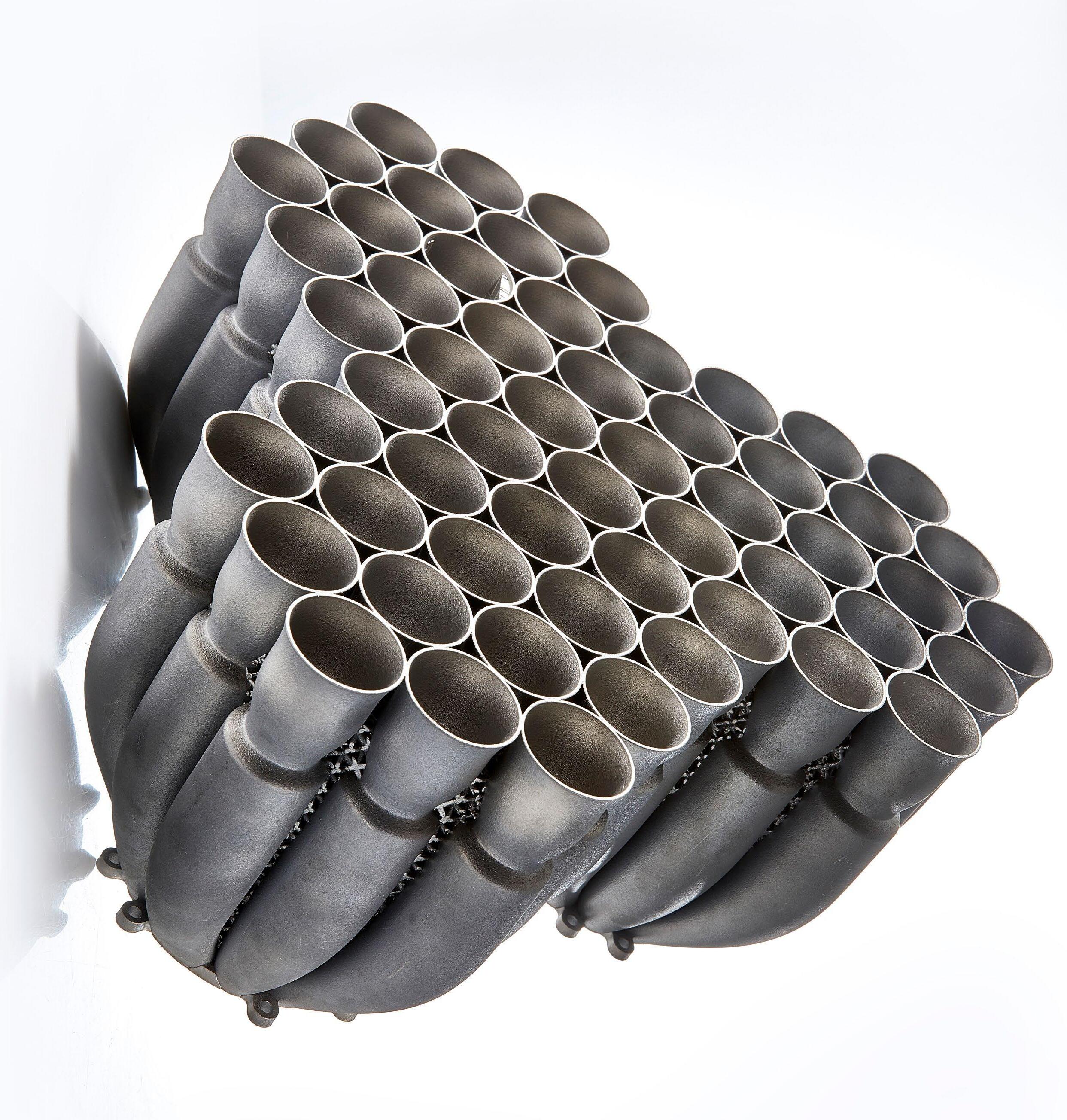
Immagine in copertina: Pezzo stampato 3D fornito da Gabriele Rizzi di Beamit
Gestione editoriale e pubblicità Publisher and marketing office: siderweb spa

Via Don Milani, 5 - 25020 Flero (BS) tel. 030 25 400 06 - fax 030 25 400 41 commerciale@siderweb.com - www.siderweb.com
La riproduzione degli articoli e delle illustrazioni è permessa solo citando la fonte e previa autorizzazione della Direzione della rivista. Reproduction in whole or in part of articles and images is permitted only upon receipt of required permission and provided that the source is cited.
siderweb spa è iscritta al Roc con il num. 26116
n.02 febbraio 2023
Anno 114 - ISSN 0026-0843
Editoriale / Editorial
A cura di Ing. Ilaria Rampin . pag.05
Memorie scientifiche / Scientific papers
Fabbricazione additiva/ Additive Manufacturing
Strutture reticolari graduate in acciaio inossidabile 316L prodotte per costruzione additiva per applicazioni di ingegneria tissutale
M.L. Gatto, E. Santecchia, M. Cabibbo, S. Spigarelli, P. Mengucci, R. Groppo .................................................. pag.08
Comparative analysis of gas atomised and recycled 316L stainless steel powders for Binder Jetting
M. Mariani, K. Salaheldin, A. Grande, N. Lecis................................................................................. pag.14
Selective laser melting di materiale composito AlCu-TiB2: processabilità, microstruttura e proprietà meccaniche
P. Bassani, C.A. Biffi, J. Fiocchi, A. Tuissi, M. Abu .......................................................................... pag.23
Attualità industriale / Industry news
Analisi e contronto di strutture reticolari mediante processi additivi a deposizione
a cura di: V. Di Pompeo, E. Santecchia, A. Santoni, M. Cabibbo, S. Spigarelli............................................................ pag.34
The effects of heat treatment on microstructure evolution of 17-4 PH single tracks deposited by AM-DED
edited by: C. Morales, M. Merlin, F. Deubdobi, A. Fortini, P. Ferrucci......................................................... pag.42
Off topic - Mathematical Modelling and Simulation
Influence of casting defects on damage evolution and potential failures in hot rolling simulation system
U. Hanoglu, B. Šarler.......................................................................................................... pag.48
Fast modelling of elastic work roll deformation in groove rolling
C. Renzing, M. Weiner, M. Stirl, M. Schmidtchen, U. Prahl............................................................................................ pag.53
TENSIL-PRO: from tensile properties calculation to incremental plasticity applications
A. Ferraiuolo, L. Ferraiuolo ................................................................................................................................................. pag.58
Optimized & adaptable cooling path control through a novel runout table controller at HSM2 of Tata Steel in IJmuiden
edited by: R.C.J.
Off topic - Gas idrati / Hydrates gas
Effetto di polveri di FeSi3 sulla formazione di idrati di metano e anidride carbonica
Le aziende di AIM/AIM's companies
Sostenibilità nell’industria siderurgica: approccio di Acciaierie Bertoli Safau
l’innovazione di prodotto e di processo
Acciaio e metalli: dinamiche, cicli e tendende di mercato
Heat Treatment & Surface En gine ering

GENOvA - ITALY
29-31 may 2023
AIM is glad to announce the ECHT 2023 Conference, to be held in Genova, at Magazzini del Cotone, on 29-31 May 2023! ECHT 2023 will cover all relevant topics for the Heat Treatment & Surface Engineering community. The Conference will have a special focus on SUSTAINABILITY! Sustainability, with its three pillars - environmental, economic and social dimensions - is playing a keyrole to address the ongoing and future challenges. The metallurgical and mechanical industry are leading the way in creating a healthy development model for the environment and for the future generations. Presentations and papers from Industry, University and Research Centres on the topic will encourage the discussion and increase awareness on the matter. We are looking forward to meeting you in beautiful Genova!



CONFERENCE VENUE
The Conference will be held in Genova, at Magazzini del Cotone (https://portoantico.it/en)


Genova sits in a prime location, which encompasses the waterfront, centre and port. The city has always been a place of exchange, gatherings, trade and invention, and it is among the most musical Italian cities in terms of the number of musicians and singer-songwriters born and bred there. It offers an endless array of gastronomic specialities, imitated all around the world.
EXHIBITION & SPONSORSHIP
The Conference will feature a technical exhibition that will represent many areas of industry with the latest equipments, facilities, products and services in the field of the conference topics.
It is now possible to register to the event!
Programme, conference fees and registration form are avaiable on the event website: www.aimnet.it/echt2023.htm

Organised by Sponsored by in cooperation with
With the support of
“Interest
additive
been
influenced the activities of the academics, in collaboration and with thesupportofindustry,to studythetechnologyin ordertoexpandtherangeof applications in which 3D can make the difference in the supplychain”
NUOVI STUDI E NUOVE SFIDE PER LE TECNOLOGIE ADDITIVE
In questo numero di febbraio vengono proposti alcuni degli studi sull’additive manufacturing presentati durante il Convegno Nazionale AIM che si è tenuto in presenza dal 21 al 23 settembre 2022 nella cornice dell’Università di Padova.
La numerosità dei lavori con filo conduttore Tecnologie Additive presentati al convegno dimostra la vivacità scientifica attorno a questa tecnologia e l’interesse nel poter capire i fenomeni che avvengono sia in fase di preparazione della materia prima che di processo e post processing.

Il mondo accademico, in collaborazione e con le aziende e a loro supporto, sta volgendo l’attenzione su diverse tematiche che comprendono l’ottimizzazione e lo sviluppo di nuove tecnologie per materiali già in uso nel
NEW STUDIES AND NEW CHALLENGES FOR ADDITIVE MANUFACTURING
February issue collects some of the studies about Additive Manufacturing presented during the AIM National Conference, which was an in-person event held from 21 to 23 September 2022 at the University of Padua.
Thelargenumberofpaperspresentedattheconference, that focused on AM topics demonstrates the scientific buzz surrounding this technology and the interest generated in understanding the phenomena that occurs during the preparation of raw materials, the process and post processing.
The academic world, in collaboration with industry evaluated various topics, which include optimization and development of new technologies for materials already in use in the 3D sector, the formulation of new
“"L’interesse per le tecnologie additive cresce e con esso la vivacità del mondo accademico, in collaborazione e a supporto delle realtà industriali, nello studio dei fenomeni ad esse collegati al fine di ampliare le applicazioni in cui il 3D può fare la differenza nella supply chain. "Ing. Ilaria Rampin Presidente del Centro Studio AIM Metallurgia delle Polveri e Tecnologie Additive
in
technologieshas
growinginthelastyears which has
settore 3D, la formulazione di materiali più performanti per raggiungere proprietà sempre più elevate e l’espansione a nuove aree di applicazioni sempre più sfidanti.
Questo è quanto traspare anche dalla selezione di memorie raccolte in questo numero.

Tra i materiali di maggiore utilizzo ci sono sicuramente gli acciai inossidabili ed in particolare AISI 316L. Esso può essere processato con le diverse tecnologie consolidate, quali PBF, DED e binder jetting, ma è ora oggetto di studio anche con nuove tecnologie quali “Material Extrusion”.
Grazie alle forme complesse e strutture alleggerite che si possono ottenere, le tecnologie sono utilizzate per impieghi sempre più ampi. Vengono in questo numero riportati casi di strutture reticolari utilizzate per applicazioni di ingegneria tissutale e casi di struttura reticolare auxetica che potrebbe essere di interesse nel settore edilizio.
Nel campo industriale la Direct Energy Deposition è un ottimo modo non solo per stampare pezzi metallici, ma, ancor più, per effettuare riparazioni o rivestimenti superficiali in grado di aumentare la resistenza alla corrosione e le proprietà meccaniche.
Non poteva mancare uno sguardo alle nuove sfide che stanno coinvolgendo trasversalmente tutto il modo metallurgico.
Nuovi scenari legati alla transazione energetica, alla sostenibilità, alla economia circolare e alla gestione della supplychain rendono le Tecnologie Additive al centro di interesse e in prima linea per le sfide che ormai sono in essere. Sempre più diventa importante avere una supply chain sostenibile nel senso ampio del termine ed è per questo che si pone attenzione a come poter utilizzare materiale di riciclo al fine di ridurre l’impatto ambientale.
materials to achieve higher properties and improved performance and the expansion to new challenging applications.
This is also reflected in the selection of articles collected in this issue.
The most frequently utilized materials is certainly stainless steels and in particular AISI 316L, which can be processed using different technologies, such as PBF, DED and binder jetting, and more recently, another technology called "Material Extrusion” is under evaluation.
Given its ability to manufacture complex and light shapes, AM technologies are used for a wide range of applications. In this issue, cases studies of reticular structures used for tissue engineering applications and auxetic reticular structures are evaluated. The last one could be of interest in the building sector.
In the industrial field, Direct Energy Deposition is an excellent way, not only to print metal parts, but even more important, to carry out repairs or surface coatings to increase corrosion resistance and improve mechanical properties.
An evaluation of the new challenges that AM technology present across the entire metallurgical world should be considered.
New scenarios related to energy transaction, sustainability, circular economy and supply chain management make Additive Technologies worthy of future evaluation and its ability to solve modern challenges. It has become more and more important to haveasustainablesupplychainandthisisthereasonwhy so much attention is focused on the possibility to use recycled material, in order to reduce the environmental impact.
METALLURGIA DI BASE PER I TRATTAMENTI TERMICI
ITrattamenti Termici rivestono ampie complessità tecnologiche la cui piena comprensione consente di affrontare, al meglio, processo e risultati.
Conoscere e gestire la trasformazione metallurgica indotta dalle particolari operazioni di questo tipo di lavorazione, già in fase di progettazione, porta a rendere il manufatto metallico totalmente idoneo al suo impiego previsto.


Questo Corso nasce quindi dalla necessità di impartire una base di nozioni metallurgiche, legate al mondo dei Trattamenti Termici, che permetta di generare un tessuto di conoscenze fondamentali, in grado di facilitare l’interpretazione degli aspetti a maggiore complessità relativi ai trattamenti in temperatura.
Tale iniziativa si rivolge in particolare a persone che devono iniziare a familiarizzare, per ragioni lavorative, con le dinamiche di trasformazione metallurgica legate ai Trattamenti Termici; pertanto, scegliendo tale opzione didattica, esse potranno accedere in maniera mirata ai successivi e coerenti percorsi di formazione specifici che AIM mette a disposizione, avendo acquisito la base di conoscenze metallurgiche propedeutiche.
La strutturazione delle docenze è stata progettata in modalità mista, ovvero le prime due giornate in presenza e la terza da remoto, per ridurre i tempi di allontanamento del partecipante dall’azienda e i costi relativi.
Il programma, guidato da docenti ad altissimo livello sia del mondo accademico che dell’industria, si sviluppa inoltre seguendo un ordine di presentazioni coerenti all’interno della singola giornata.

Questo proprio con l’obbiettivo di guidare il partecipante all’apprendimento, partendo dai processi chimico-fisici delle soluzioni solide passando ai metodi di produzione dei manufatti metallici, all’introduzione dei trattamenti termici maggiormente utilizzati e arrivando alle tecniche analitiche di controllo oltre a cenni sugli aspetti impiantistici.
Per informazioni e iscrizioni:

Via F. Turati, 8 20121 Milano
Tel. +39 0276397770
e-mail: met@aimnet.it www.aimnet.it


Strutture reticolari graduate in acciaio inossidabile 316L prodotte per costruzione additiva per applicazioni di ingegneria tissutale
M.L. Gatto, P. Mengucci, E. Santecchia, M. Cabibbo, S. Spigarelli, R. GroppoL’impianto di scaffold è una pratica emergente nel trattamento della rigenerazione tissutale. Per permettere la ricrescita del tessuto osseo e il recupero delle sue funzionalità, lo scaffold deve essere biocompatibile e rispondere alle esigenze biomeccaniche dell’osso. Le geometrie reticolari graduate rappresentano una potenziale soluzione per soddisfare tali esigenze, poiché forniscono alla struttura un gradiente poroso adattativo, permettono di progettare il comportamento a deformazione dello scaffold e, a lungo termine, la sua vascolarizzazione. Le tecnologie di costruzione additiva sono adatte alla produzione di strutture reticolari graduate. In particolare, la tecnica di fusione a letto di polvere con sorgente laser permette di raggiungere un livello elevato di accuratezza anche in caso di pattern intricati e strutture micrometriche. Tra i vari metalli usati per la rigenerazione del tessuto osseo, la soluzione con maggior costo-efficacia per impianti a breve termine è l’acciaio inossidabile 316L, ampiamente usato nella sostituzione della coppa acetabolare nell’articolazione dell'anca, piastre e viti e innesti orali. In questo lavoro, scaffold ossei con due differenti reticoli graduati sono stati prodotti in 316L tramite fusione a letto di polvere. Le prestazioni biomeccaniche delle impalcature sono state valutate sperimentalmente e i risultati sono stati correlati alla micro e macro struttura degli scaffold. I risultati hanno evidenziato che geometrie reticolari graduate permettono di progettare il comportamento meccanico e biologico di scaffold per applicazioni tissutali ossee.
PAROLE CHIAVE: COSTRUZIONE ADDITIVA; SCAFFOLD RETICOLARI GRADUATI; ACCIAIO INOSSIDABILE; TESSUTO OSSEO
INTRODUZIONE
Le tecnologie di costruzione additiva per la produzione di dispositivi biomedicali in 316L potrebbero mitigare il rischio di fallimento dell'impianto, migliorando il comportamento a corrosione del biomateriale. Infatti il 316L prodotto additivamente ha dimostrato una biocompatibilità superiore in ambienti biologici aggressivi rispetto al 316L forgiato [1]. In particolare, l'elevata resistenza alla corrosione del campione prodotto da fusione a letto di polvere con sorgente laser ha limitato il rilascio di ioni tossici nell'ambiente biologico, con conseguente miglioramento della vitalità e proliferazione delle cellule pre-osteoblastiche, come studiato da AlMamun et al. [1]. Inoltre, Kong et al. [2] hanno riscontrato un aumento della concentrazione e della proliferazione
cellulare in corrispondenza dell'aumento della potenza laser e, a circa 200 W, i campioni hanno mostrato una biocompatibilità notevolmente superiore rispetto al 316L lavorato con tecniche tradizionali.
In strutture reticolari graduate, la gradazione funzionale (variazione delle dimensioni, della tipologia, del materiale o del diametro dello strut) consente di progettare il meccanismo di rottura dello scaffold, attraverso il controllo della densità relativa locale delle cellule unitarie. In questo modo, il riempimento graduato consente di progettare un impianto ortopedico con una rigidità localmente corrispondente a quella dell'osso target [3]. Lo scopo di questo studio è progettare il comportamento meccanico e biologico di scaffold in acciaio inossidabile 316L prodotti mediante fusione a letto di polvere con sorgente laser, per applicazioni cliniche a breve termine.
MATERIALI E METODI
Le geometrie degli scaffold a reticolo graduato densein e dense-out sono state progettate con Autodesk Netfabb (Inc., San Rafael, CA) e riportate in Figura 1. Gli scaffold cubici con lato di 10 mm, sono stati ottenuti ripetendo nello spazio una cella elementare dodecaedrica rombica. La struttura graduata è stata ottenuta variando le dimensioni degli strut della cella elementare strato per strato lungo la direzione di costruzione (Figura 1). Sono stati utilizzati valori di spessore degli strut compresi tra 0.25 e 0.75 mm, con un passo di 0.25 mm. Nella geometria dense-in le dimensioni degli strut diminuiscono dal centro al bordo, mentre nella geometria dense-out le dimensioni degli strut aumentano dal centro al bordo (Figura 1). Entrambe le geometrie sono state costruite con simmetria speculare rispetto all'asse orizzontale centrale, quindi gli scaffold sono composti da un totale di cinque strati, come osservabile in Figura 1.
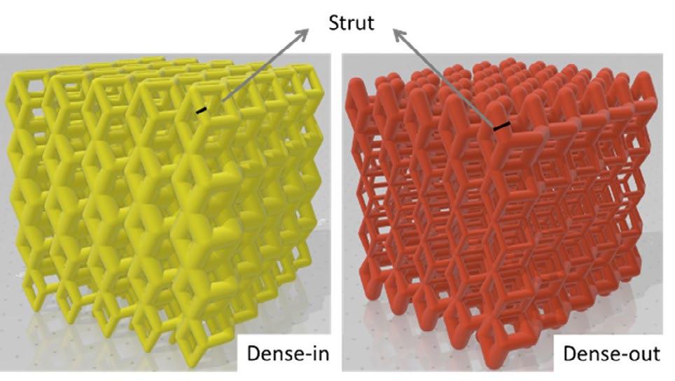
La porosità totale degli scaffold dense-in e dense-out ricavata dal file STL è rispettivamente del 58% e del 72%. Gli scaffold sono stati realizzati a partire da polvere di acciaio inossidabile 316L (LPV CARPENTER technology) mediante fusione a letto di polvere con sorgente laser, con un sistema 3D4steel (3D4Mec Srl, Sasso Marconi, Italia), utilizzando parametri di stampa ottimizzati all’interno delle finestre operative di seguito riportate: Potenza laser 200 – 270 W, Velocità di scansione 400 – 1000 mm/s, Distanza di hatching 0.10 - 0.14 mm, Spessore dello strato 0.02 - 0.06 mm.
La caratterizzazione strutturale e meccanica degli scaffold è stata eseguita mediante tecniche di microscopia elettronica a scansione, spettroscopia a dispersione
di energia, diffrazione di raggi X, micro-tomografia computerizzata a raggi X e test meccanici a compressione. Le prestazioni biologiche degli scaffold sono state testate mediante vitalità di cellule di osteosarcoma umano MG63 a 24 ore e 7 giorni di incubazione, con saggio MTT.
RISULTATI E DISCUSSIONE
La composizione chimica della polvere e degli scaffold dense-in e dense-out, valutata tramite spettroscopia a dispersione di energia, è comparata in Tabella 1. Gli scaffold mostrano un lieve aumento di manganese e silicio rispetto alla polvere, mentre la quantità di cromo e molibdeno (stabilizzatori della ferrite) e nichel (stabilizzatori dell’austenite) rimane pressoché invariata.
Tale fenomeno è noto e Salman et al. [4] concludono che l’acciaio inossidabile 316L prodotto per fusione a letto di
polvere con sorgente laser, contenga nano-precipitati amorfi sferici ricchi di Mn-Si.
Tab.1 - Composizione chimica (% in peso) della polvere e degli scaffold reticolari graduati dense-in e denseout, valutata mediante spettroscopia a dispersione di energia. / Experimental chemical composition (wt.%) from energy dispersive spectroscopy of raw powder, dense-in and dense-out graded lattice scaffolds.
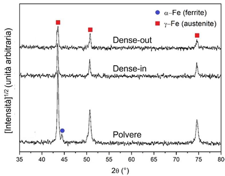
I diffrattogrammi degli scaffold dense-in e dense-out sono riportati in Figura 2 insieme al pattern di diffrazione della polvere, per comparazione. In Figura 2 i pattern sono graficati nell’intervallo angolare 2θ = 35° - 80° in scala di radice quadrata dell’intensità ([Intensità] 1/2). I
risultati mostrano chiaramente la presenza di α-Fe (ferrite) solo nella polvere, mentre gli scaffold sono interamente formati da γ-Fe (austenite). Dall’analisi Rietveld eseguita con il software MAUD, la quantità di α -Fe (ferrite) stimata nella polvere è circa il 3% in peso.
- Pattern di diffrazione dei raggi X di polvere e scaffold reticolari graduati dense-in e dense-out. / X-rays diffraction patterns of powder, dense-in and dense-out graded lattice scaffolds.
I parametri morfometrici degli scaffold, come porosità chiusa e aperta, ottenuti dall’analisi micro-tomografica a raggi X, sono elencati in Tabella 2. La micro-porosità all’interno del materiale bulk è responsabile della porosità chiusa, che a sua volta determina la densità del materiale. D’altra parte i macro-pori sono legati alla geometria della cella elementare unitaria e costituiscono la porosità aperta [5]. Quindi, mentra la porosità aperta è determinata dal design della cella elementare unitaria, la porosità chiusa è influenzata dai parametri di stampa e dal rate di raffreddamento durante il processo produttivo.
Il mismatch tra i valori di porosità forniti dal file STL e quelli sperimentali della geometria dense-in sono dovuti principalmente alla presenza di polvere residua rimasta intrappolata nel centro dello scaffold durante il processo produttivo.
I valori di porosità chiusa di entrambe le geometrie confermano che l’ottimizzazione dei parametri di stampa ha permesso la realizzaizone di strutture pienamente dense.
Tab.2 - Parametri morfometrici degli scaffold, ottenuti tramite analisi micro-tomografica a raggi X. / Scaffold morphometric parameters obtained from X-rays micro-computed tomography analysis.
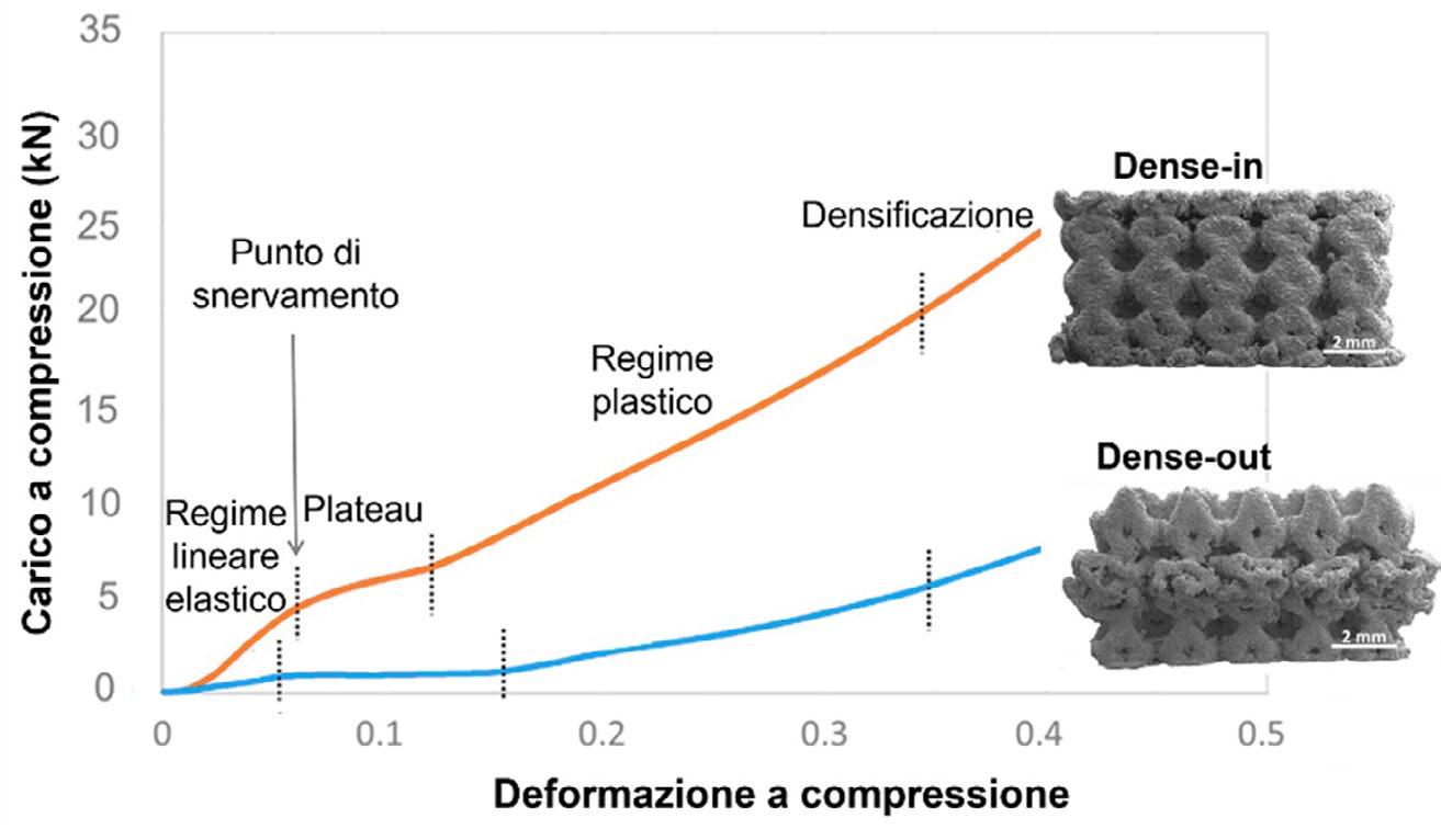
Le prestazioni meccaniche a compressione degli scaffold reticolari graduati dense-in e dense-out sono illustrate in Figura 3 come carico su deformazione a compressione. Come evidenziato in Figura 3, il comportamento meccanico degli scaffold può essere descritto da 4 regimi: regime lineare elastico, plateau, regime plastico e densificazione. Le osservazioni al microscopio elettronico a scansione dopo le prove di compressione sono mostrate in Figura 3. I risultati meccanici mostrano che la deformazione plastica di dense-in e dense-out coinvolge inizialmente le celle elementari con spessore degli strut più sottili (0.25 mm), a causa dell’elevata concentrazione degli stress sulle giunzioni degli strut [6]. Questo significa che nella geometria dense-in la deformazione plastica a seguito della compattazione delle celle, avviene negli strati più esterni di entrambi i lati dello scaffold. Al contrario, nella
geometria dense-out, la deformazione e la compattazione riguardano le celle all’interno dello scaffold con spessore degli strut inferiore.
A prescindere dalla geometria, l’assenza di oscillazioni nelle curve di compressione suggerisce che quando gli strut più sottili raggiungono la fase di densificazione, gli strut più spessi sono ancora in regime di plateau; pertanto differenti meccanismi di deformazione sono attivi simultaneamente durante la compresisone di strutture reticolari graduate.
La massima resistenza a compressione risulta 255±15 MPa per la geometria dense-in e 80±6 MPa per dense-out; tale valore è prossimo al valore sperimentale dell’osso corticale [7].
Fig.3 - Comportamento meccanico a compressione degli scaffold reticolari graduati dense-in (curva arancione) e dense-out (curva celeste). Quattro diversi regimi meccanici sono indicati nelle curve. Immagini al microscopio elettronico a scansione dopo il test di compressione sono riportate per gli scaffold dense-in e dense-out. / Mechanical behavior under compression of dense-in (orange) and dense-out (light blue) graded lattice scaffolds. Four different mechanical regimes are indicated in the curves. Scanning electron microscope images of scaffolds after compression test are reported for both the scaffold geometries.
A seguito della semina cellulare, la vitalità cellulare è stata investigata dopo 24 ore e 7 giorni di coltura sugli scaffold dense-in e dense-out (Figura 4). A 24 ore non si rilevano differenze significative tra gli scaffold, mentre dopo 7
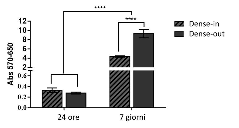
giorni di incubazione, un maggiore livello di vitalità è individuato nella geometria dense-out, dove le cellule risultano metabolicamnete più attive.
CONCLUSIONI
Allo scopo di studiare la progettazione di scaffold con migliori prestazioni biomeccaniche per la rigenerazione del tessuto osseo, sono state prodotte due diverse strutture reticolari graduate in acciaio inossidabile 316L mediante fusione a letto di polvere con sorgente laser. Variando strato per strato la dimensione degli strut della cella elementare rombica dodecaedrica nella direzione di costruzione, sono stati prodotti scaffold con geometria dense-in e dense-out. La dimensione degli strut decresce in dense-in e aumentata in dense-out dal centro al bordo, con simmetria speculare rispetto allo strato centrale. È stata eseguita una caratterizzazione strutturale e meccanica e una validazione biologica degli scaffold e i risultati principali possono essere riassunti come segue:
• La fusione a letto di polvere con sorgente laser è una tecnologia adatta alla produzione di strutture reticolari graduate con un elevato livello di precisione.
• Le prove di compressione hanno evidenziato che la deformazione plastica nei reticoli graduati coinvolge in primo luogo gli strut di dimensioni minori. Pertanto, la sequenza temporale della deformazione subisce uno shift dipendente delle dimensioni dei strut.
Gli strut più sottili raggiungono la densificazione quando quelli più spessi risultano ancora in regime di plateau, determinando così il diverso comportamento meccanico dei reticoli graduati dense-in e dense-out. La geometria dense-out mostra proprietà meccaniche vicine all'osso corticale;
• La validazione biologica dopo 24 ore e 7 giorni di incubazione mostra che la geometria dense-out migliora la proliferazione cellulare rispetto a dense-in. Questo effetto è dovuto principalmente alla maggiore dimensione dei pori nel centro della struttura 3D, che facilita la diffusione di nutrienti e ossigeno alle cellule.
In conclusione, grazie soprattutto alle proprietà biologiche e meccaniche, gli scaffold reticolari graduati in acciaio inossidabile 316L, possono essere considerati per la rigenerazione del tessuto osseo.
È possibile migliorare le prestazioni biomeccaniche degli scaffold controllando adeguatamente i parametri di produzione nel processo di fusione a letto di polvere con sorgente laser e la geometria delle celle elementari delle strutture graduate.
Scientific papers - Additive manufacturing
BIBLIOGRAFIA
[1] Al-Mamun, N. S., Deen, K. M., Haider, W., Asselin, E., & Shabib, I. (2020). Corrosion behavior and biocompatibility of additively manufactured 316L stainless steel in a physiological environment: The effect of citrate ions. Additive Manufacturing, 34, 101237.
[2] Kong, D., Ni, X., Dong, C., Lei, X., Zhang, L., Man, C., ... & Li, X. (2018). Bio-functional and anti-corrosive 3D printing 316L stainless steel fabricated by selective laser melting. Materials & Design, 152, 88-101.
[3] Al-Ketan, O. (2021). Programmed Plastic Deformation in Mathematically-Designed Architected Cellular Materials. Metals, 11(10), 1622.
[4] Salman, O. O., Gammer, C., Chaubey, A. K., Eckert, J., & Scudino, S. (2019). Effect of heat treatment on microstructure and mechanical properties of 316L steel synthesized by selective laser melting. Materials Science and Engineering: A, 748, 205-212.
[5] Gatto, M. L., Furlani, M., Giuliani, A., Bloise, N., Fassina, L., Visai, L., & Mengucci, P. (2021). Biomechanical performances of PCL/HA micro-and macro-porous lattice scaffolds fabricated via laser powder bed fusion for bone tissue engineering. Materials Science and Engineering: C, 128, 112300.
[6] Onal, E., Frith, J. E., Jurg, M., Wu, X., & Molotnikov, A. (2018). Mechanical properties and in vitro behavior of additively manufactured and functionally graded Ti6Al4V porous scaffolds. Metals, 8(4), 200.
[7] Gatto, M. L., Groppo, R., Bloise, N., Fassina, L., Visai, L., Galati, M., Iuliano, L., & Mengucci, P. (2021). Topological, Mechanical and Biological Properties of Ti6Al4V Scaffolds for Bone Tissue Regeneration Fabricated
Graded lattice scaffolds in 316L stainless steel by additive manufacturing for tissue engineering
Scaffold implantation is an emerging practice in tissue regeneration field. Scaffold must be biocompatible and meet the biomechanical requirements of bone, for allowing tissue regrowth and recovery of its functionalities. Graded lattice geometry is a potential solution to fulfill these needs, since it provides an adaptive porous gradient, allowing the designing of scaffold deformation behavior and, in long term, its vascularization. Additive manufacturing technologies are suitable for the production of graded lattice scaffold. In particular, laser powder bed fusion technique permits to achieve a high level of accuracy, even in the case of intricate patterns and micro-architectures. Among the various metals used for bone tissue regeneration, the most cost-effective solution for short-term implants is 316L stainless steel, which is widely used in acetabular cup replacement in the hip joint, plates and screws, and oral grafts. In this work, bone scaffolds with two different graded lattice geometries were fabricated in 316L by laser powder bed fusion technology. The biomechanical performances of scaffolds were experimentally evaluated, and the results were correlated with the micro and macro structure of the scaffolds. The results showed that graded lattice geometries allow designing the mechanical and biological behavior of scaffolds for bone tissue applications.
KEYWORDS: ADDITIVE MANUFACTURING; GRADED LATTICE SCAFFOLD; STAINLESS STEEL; BONE TISSUE
Comparative analysis of gas atomised and recycled 316L stainless steel powders for Binder Jetting
M. Mariani, K. Salaheldin, A. Grande, N. LecisIn our work, we investigate the suitability of a 316L stainless steel powder from scrap metal recycling for binder jetting and the results are compared to those obtained for a gas atomised feedstock. First, the main morphological features of the particles, in particular sphericity and size distribution, are measured by static image granulometry and scanning electron microscopy. Then, the dispensing rate and the printer deposition parameters are optimised to obtain a smooth and homogeneous powder bed. After printing, the building box is cured at 180 °C to consolidate the green components, whose density and geometrical accuracy are determined by caliper measurement. Finally, the microstructural and mechanical properties of the vacuum sintered specimens are studied. Phase composition is determined by x-ray diffraction and microscopy, with specific attention to δ-ferrite formation at the grain boundary. Hardness is evaluated by Vickers micro-indentation and compared to typical properties of 316L by conventional manufacturing.
KEYWORDS: BINDER JETTING; 316L STAINLESS STEEL; SINTERING; AUSTENITE; FERRITE
INTRODUCTION
Additive manufacturing (AM) comprises a long series of techniques suitable to produce components with a high degree of geometrical complexity. Among these processes, metal binder jetting (BJT) is progressively gathering the interest of the academic and industrial sectors due to a series of advantages. This technique is based on a first shaping phase, during which a liquid bonding agent is deposited on a powder bed in a layerwise manner according to the specimen design, followed by a series of post-processing treatments. In detail, curing at low temperature induces the polymerisation of the liquid species to consolidate the green bodies, debinding removes any trace of organic material and sintering promotes the removal of porosity and the densification of the components. If needed, additional treatments as hot isostatic pressing, slurry infiltration, annealing, and others, may be performed to modify or improve the performances of the printed parts.
The main advantage of BJT lies in the possibility of obtaining a finer control on the microstructural properties, thus on mechanical ones too, with respect to powder bed fusion techniques due to proper tuning of the heat treatments, as occurs in conventional powder metallurgy techniques
Dipartimento
Dipartimento di Scienze e Tecnologie Aerospaziali, Politecnico di Milano
*nora.lecis@polimi.it
Scientific papers - Additive manufacturing

(e.g. powder forging, metal injection moulding…) (1). Secondarily, geometrical limitations to the designs are minimal, namely only closed cavities, differently from other direct and indirect AM techniques that requires supports for overhangs, limited step angles and so on (2). The main drawback consists in the strong dependence of the sintered components features on the feedstock material employed during printing. Indeed, the powder influences the mechanisms of formation of the components during the initial shaping phase and densification at later stages. Powder morphology (shape and size distribution), chemical composition and surface properties are responsible for the feedstock flowability, which is the main contribution to the proper packing of the particles in the building box, thus to the green body density (3,4). Maximising the green density facilitates the sintering process, however other phenomena must be kept into account to understand densification mechanisms. Indeed, necking and shrinkage rates are dependent not only on coordination numbers of the particles, but also on the specific composition of the feedstock that affects phase transformations, diffusion mechanisms and liquid phase formation (5). Exceeding the solidus temperature has become a common trend in metal BJT because liquid sintering allows to rapidly fill residual porosity, however a fine control on the elemental composition is needed (6–8) and possible shape distortions should be accounted for. In this study, two feedstocks of 316L stainless steel are employed to observe the effects of chemical composition variations on each step of production by BJT. A comparative analysis of the microstructural properties is performed and correlated to densification mechanisms according to phase transformation modelling.
MATERIALS AND METHODS
Samples production
Two 316L stainless steel feedstocks are mentioned in the study:
“F”) A spherical powder from f3nice Srl obtained from atomisation of recycled scrap steel;
“S”) A spherical powder from Sandvik AB produced from gas atomisation of molten metal with controlled chemical composition.
Powder F properties and performances are compared to powder S, which has been extensively studied and described in literature.
The components were manufactured with an Innovent+ printer from ExOne with deposition and spreading parameters optimised according to the flowability of each feedstock, a layer thickness (LT) of 50 μm and a binder saturation (BS) of 55% and 70%. Three sizes of parallelepiped specimens were produced: small (8 x 6 x 4 mm3), medium (16 x 12 x 18 mm3) and large (24 x 18 x 12 mm3). The parts underwent the following thermal treatments, optimised in previous studies (6,9,10):
1. Curing at 180 °C for 6 hours in natural air convection furnace YAMATO DX 412C to polymerise the polyethylene glycol (PEG) precursors contained in the binder and consolidate the green bodies;
2. Debinding at 470 °C for 4 hours in Ar in a tubular furnace CARBOLITE 12/75/700 to remove almost entirely the organic traces without oxidating the materials;
3. Sintering at 1360 °C for 3 hours in a vacuum (10 -1 mbar) furnace HTS HT-S1 LPC to densify the components.
Samples characterisation
First, the powders were characterised with a static image optical granulometer Malvern Morphology 4 and x-ray diffractometer (XRD) SmartLab SE Rigaku. The chemical composition is determined by inductively coupled plasma (ICP) atomic emission spectroscopy on pristine particles. Then, the printed samples were analysed geometrically to assess their accuracy and density at the green and brown stages. Archimedes’ density was measured only for the sintered bodies. In both cases, the theorical density was set at 7.83 g cm-3, as calculated from thermodynamic modelling based on the specific chemical composition of powder F. Microstructural features, such as grains, pores and secondary phases, were studied by field emission scanning electron microscopy (FE-SEM) equipped with energy dispersive x-ray (EDX) detector (Zeiss Sigma 500) and optical microscopy (Nikon Eclipse LV250NL), combined with XRD to determine the phase composition.
Vickers hardness was evaluated at the core and superficial (2 mm from the surface) regions of large samples with an applied load of 300 gf for 15 s.
Phase transformation modelling
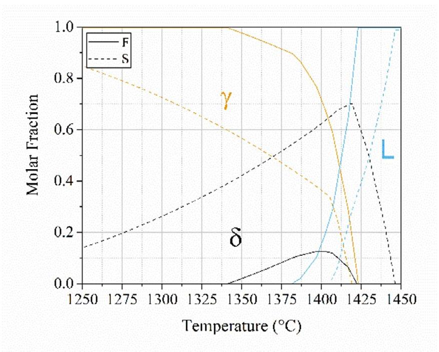
Phase transformation mechanisms occurring during sintering are studied by CALPHAD-based simulations performed by ThermoCalc AB software under the hypothesis of thermodynamic equilibrium. One axis phase diagrams were modelled for the two powder based on their che-
mical compositions, as measured by ICP. Phase diagrams accounting for Cr, Ni and Mo mass percentages variations were calculated starting from the aforementioned chemical compositions with an addition of 0.1% in mass of C to simulate carbon-pickup from organic residue.
RESULTS AND DISCUSSION Pre-sintering characterisation
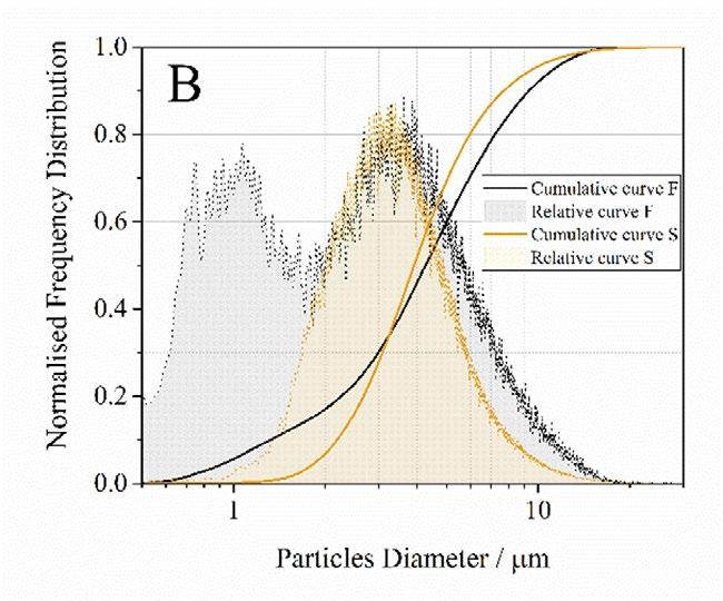
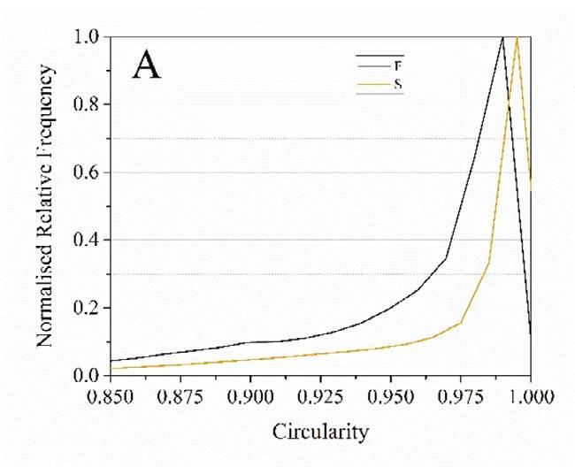
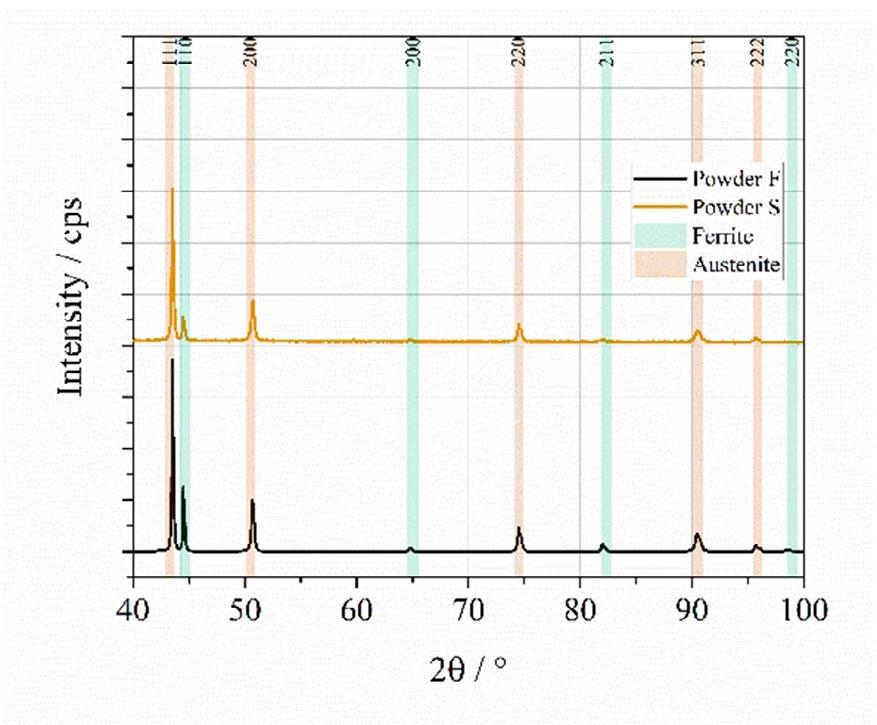
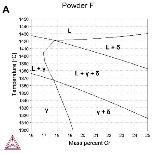
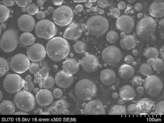
As can be seen from Fig. 2A, both feedstocks display an optimal circularity, which should grant a decent flowability and packing behaviour during the printing phase, while the size distribution curves (Fig. 2B) underline a minimal distinction. Indeed, the F powder features an ultrafine fraction (500 nm – 1.5 μm) that is absent in the other feedstock. From the XRD spectra in Fig. 3, it appears that powder F contains a larger fraction of ferrite which could be either due to the specific chemical composition and to the atomisation process parameters as heating and cooling rates. According to the elemental compositions in Tab. 1, the concentration of ferritising elements in the two feedstocks is comparable, while that of austenitising ones is more relevant (the sharp increase of Ni, compensates for the decrease of Mn) in powder F. From simulation of phase formation diagrams at the equilibrium (Fig. 4), a higher content of ferrite should be expected in powder S, meaning that the thermal cycles applied to the powders during production are determinant on phases formation.
The measure of the relative density values of the green and brown components in Tab. 2 reveals that:
- Small components have a lower density, likely due to a more relevant effect of small surface defects on the estimate of the pieces volume (also highlighted by the larger values standard deviations).
- BS70% components feature a higher density both at the green stage (due to the larger content of binder) and at the brown stage (mainly due to improved particles retention during handling before debinding).
- Weight loss from debinding is minimal as expected from the low amount of polymer in the binder (6). The relative densities are lower than those obtained from powder S, whose average values were above 55% for both conditions after curing (6), thus the packing
behaviour of powder F is poorer. Considering that the phase compositions and the circularity of the particles are similar in the two cases, the lower density should be ascribed to the size distributions. As seen in Fig. 2B, powder F features an additional ultrafine fraction that may responsible for a lower flowability of the particles due to rising of electrostatic interactions and residual humidityinduced capillarity among particles with reduced diameter (11). From literature, multimodal distributions should improve particles packing, but the ratio of diameters and volume fractions of the fine and coarse fractions should be properly optimised and all particles need a sufficient flowability, which is not occurring in this case (12).
Tab.2 - Relative densities of green, brown and sintered components obtained from f3nice (F) powders with binder saturation of 55% and 70% / Densità relative dei component verdi, decerati e sinterizzati ottenuti dalle polveri f3nice (F) con una saturazione di legante pari al 55% e al 70%.
Post-sintering characterisation
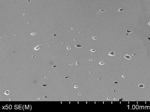
The sintering treatment succeeded in reaching the final stage, where residual porosity is closed and rounded, as can be seen from Fig. 5. This is to be expected considering that the sintered relative densities (from Archimedes’ method) are close or above 90% depending on the size and binder saturation of the samples (see Tab. 2). As expected, smaller samples densify faster because internal thermal gradients are minimised and pores diffusion toward the surface is shortened (13), while large components tend to retain residual porosity in the core regions (14,15). This inhomogeneity in pores distribution is confirmed by image analysis on micrographs from large BS55% samples, indeed porosity fractions of 8.3 ± 2.5%
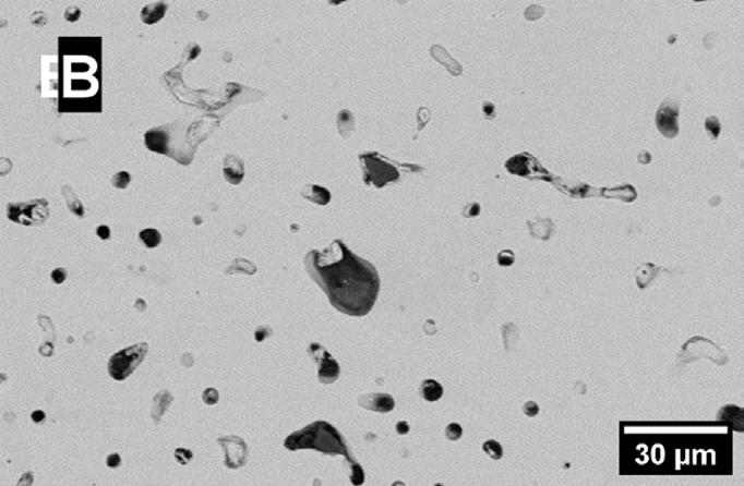
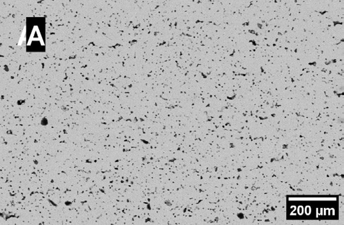
and 10.7 ± 1.9% were detected at the superficial and core areas, and by microhardness measurements with values of 90.1 ± 13 HV and 107.5 ± 16 HV at the centre and side of the samples, respectively. The detrimental effect of larger binder saturation is confirmed and enhanced in the case of medium and large parts. Indeed, densification rates are equal to +44.7% and + 41.4% for BS55% and BS70% respectively. Although specimens integrity and density may be improved at the green and brown stages, the excess porosity left after polymer burnout negatively affects densification because it tends to be larger and concentrated at the layer interfaces where binder is deposited (16).
Microstructural analysis
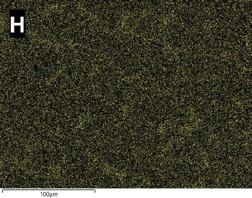
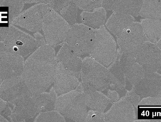
The comparative analysis of the microstructures obtained from the two feedstocks reveals that both the residual porosity amounts, and the phase distributions are different. Indeed, specimens F were less densified (98.3 ± 0.1% vs 91.7 ± 1.7% relative densities of BS55% for powder S and F, respectively) and they do not feature the marked presence of δ-ferrite at the grain boundaries that
was evident in specimens S. Ferrite could be found only in specific spots and within limited regions, as can be seen in Fig. 6.
The lower green density hinders densification mechanisms, however the different phase distribution suggests that also other aspects should be considered. First, distinct chemical compositions of the feedstocks affect the stability range of austenite at high temperatures
and the formation of ferrite and liquid phases. In addition, elements distributions within particles are not uniform: Cr and Mo tends to segregate at the grain boundaries due to self-diffusion mechanisms, thus enriching the core of the particles with austenitising elements (17). Finally, carbon pickup from binder residue on particles surfaces might occur, as debinding in argon is incomplete (6,18). Phase diagrams obtained from equilibrium simulations (Fig. 4) show that austenitising elements expand the stability window of the γ phase and reduce that of δ , thus increasing the temperature of formation of the ferrite and slightly reducing that of the liquid phase, even though it still stands above 1380 °C. At 1360 °C, powder F features about 5 mol.% of δ-ferrite concentrated at the grain boundary where Cr tends to segregate, while in powder S it should amount to about 45 mol.% as consequence
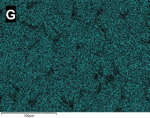
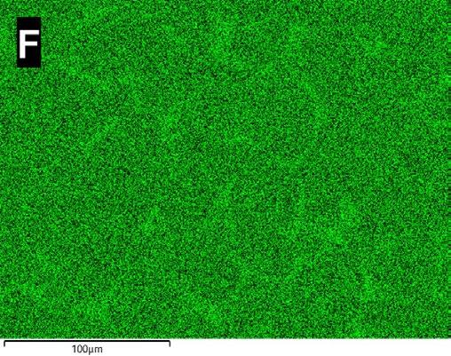
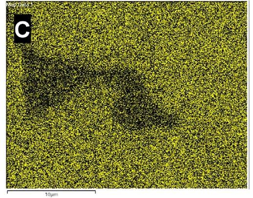
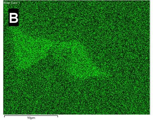
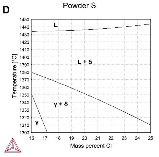
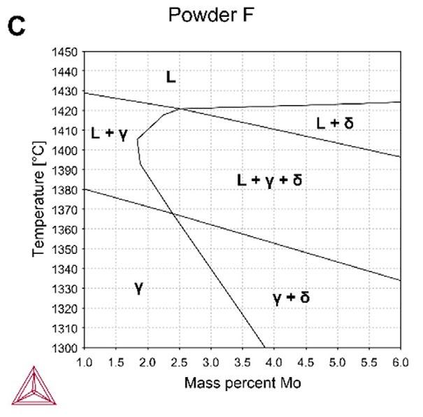
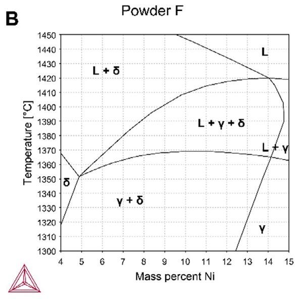
of the lower amount of Ni in the composition. The study of phase diagrams with varying concentrations of Cr, Ni and Mo in Fig. 7 demonstrate that local fluctuations in the concentration of alloying elements can be responsible for the reduction of the solidus line below the sintering temperature. By considering the variations of compositions (enrichment of Cr and Mo, and reduction of Ni) at the grain boundaries, as deducted from the EDX measurements in Tab. 3, it can be observed that Cr and Mo increase to 24% and 4% in mass, respectively, can lead to liquid phase formation well below 1360 °C. Ferritising elements (Cr, Mo and C) effectively reduce the solidus line, thus favouring the formation of liquid phase prior to complete melting and increasing the pore filling effect required for densification (19).
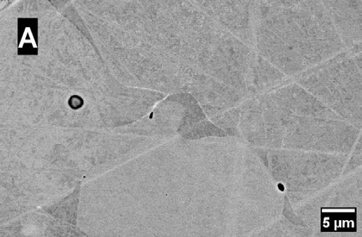
Tab.3 - Elemental composition (mass percentages) measured by EDX of the phases γ e δ in samples BS55% from f3nice (F) e Sandvik (S) powders / Composizione elementale (in massa percentuale) misurata tramite EDX della fase γ e δ nei campioni BS55% da polveri f3nice (F) e Sandvik (S).
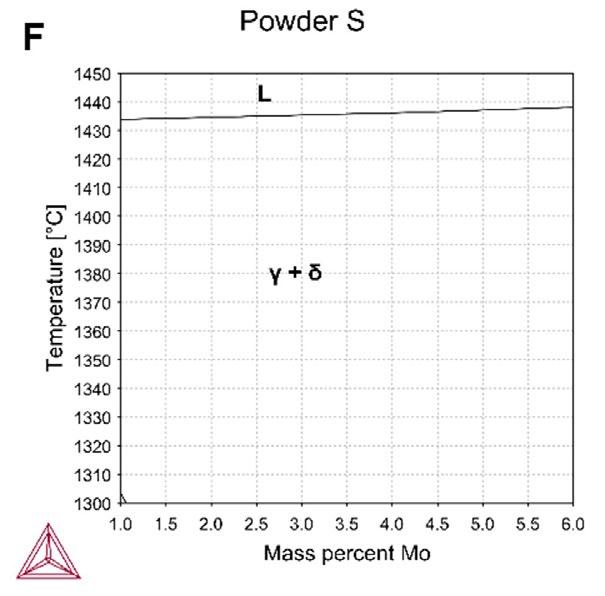
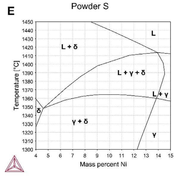
Fig.7 - Phase diagrams calculated from the chemical composition of the f3nice-F (A,B,C) and Sandvik-S (D,E,F) powders by varying the mass percentages of Cr (A,D), Ni (B,E) and Mo (C,F) / Diagrammi di fase calcolati dalle composizioni chimiche di A,B,C) polveri f3nice (F) e D,E,F) Sandvik (S) al variare della massa percentuale di Cr (A,D), Ni (B,E) e Mo (C,F).
CONCLUSIONS
This work analyses the effects of powder features and binder jetting procedures (printing phase and thermal treatments) on the microstructural properties of the final components. The employment of particles of the same nominal material (stainless steel 316L) allows to underline which are the main mechanisms of densification and how the effective chemical composition of the feedstocks affects the phase transformation mechanisms.
In particular, it was observed that the larger concentration of austenitising elements stabilises the γ phase at the sintering temperature, preventing the formation of large fractions of liquid phase, thus densification by supersolidus liquid phase sintering (SLPS). As a consequence, residual porosity at the grain boundaries is increased and grain boundaries decoration by δ-ferrite is minimised.
In conclusion, materials design is fundamental to determine the effective properties of the 3D printed components and
Scientific papers - Additive manufacturing
specific attention should be placed on assessing the effect of alloying elements on sintering mechanisms and phase transformations.
ACKNOWLEDGEMENTS
The authors acknowledge the support provided by f3nice Srl for the powder supply. The authors would like
BIBLIOGRAFIA
to acknowledge also the “Functional Sintered Materials (Funtasma)” Interdepartmental Laboratory of Politecnico di Milano, where this research activity was developed and the support by the Italian Ministry for Education, University and Research through the project Department of Excellence LIS4.0 (Integrated Laboratory for Lightweight e Smart Structures).
[1] Kumar P, Jayaraj R, Suryawanshi J, Satwik UR, McKinnell J, Ramamurty U. Fatigue strength of additively manufactured 316L austenitic stainless steel. Acta Mater. 2020 Oct 15;199:225–39.
[2] Zago M, Lecis NFM, Vedani M, Cristofolini I. Dimensional and geometrical precision of parts produced by binder jetting process as affected by the anisotropic shrinkage on sintering. Addit Manuf. 2021 Jul 1;43:102007.
[3] Diener S, Zocca A, Günster J. Literature Review: Methods for achieving high powder bed densities in ceramic powder bed based additive manufacturing. Open Ceram. 2021 Sep 27;8:100191.
[4] Mariani M, Frias Blanco G, Mercadelli E, Sánchez-Herencia AJ, Galassi C, Lecis N, et al. Tailoring α-alumina powder morphology through spray drying for cold consolidation by binder jetting. Open Ceram. 2022 Dec 25;12:100307.
[5] Liu J, Lal A, German RM. Densification and shape retention in supersolidus liquid phase sintering. Acta Mater. 1999 Dec 10;47(18):4615–26.
[6] Lecis N, Mariani M, Beltrami R, Emanuelli L, Casati R, Vedani M, et al. Effects of process parameters, debinding and sintering on the microstructure of 316L stainless steel produced by binder jetting. Mater Sci Eng A. 2021 Nov 2;828:142108.
[7] Liu J, Kannan R, Zhang D, Liu T, Nandwana P, Devaraj A. Multi-scale characterization of supersolidus liquid phase sintered H13 tool steel manufactured via binder jet additive manufacturing. Addit Manuf. 2022 Apr 20;56:102834.
[8] Mariani M, Goncharov I, Mariani D, De Gaudenzi G Pietro, Popovich A, Lecis N, et al. Mechanical and microstructural characterization of WC-Co consolidated by binder jetting additive manufacturing. Int J Refract Met Hard Mater. 2021 Nov 1;100:105639.
[9] Lecis N, Beltrami R, Mariani M. Binder jetting 3D printing of 316 stainless steel: Influence of process parameters on microstructural and mechanical properties. Metall Ital. 2021;113(2):31–41.
[10] Mariani M, Beltrami R, Meneghetti F, Azzollini D, Lecis N. Effect of Printing Parameters on the Mechanical Strength of Green Body from Binder Jetting Additive Manufacturing. In: Proceedings - Euro PM2020 Congress and Exhibition. EPMA; 2020.
[11] Baesso I, Karl D, Spitzer A, Gurlo A, Günster J, Zocca A. Characterization of powder flow behavior for additive manufacturing. Addit Manuf. 2021 Nov 13;47:102250.
[12] Bai Y, Wagner G, Williams CB. Effect of Particle Size Distribution on Powder Packing and Sintering in Binder Jetting Additive Manufacturing of Metals. J Manuf Sci Eng. 2017 Aug 1;139(8).
[13] Mariani M, Beltrami R, Brusa P, Galassi C, Ardito R, Lecis N. 3D printing of fine alumina powders by binder jetting. J Eur Ceram Soc. 2021 Aug 8;41(10):5307–15.
[14] Huber D, Vogel L, Fischer A. The effects of sintering temperature and hold time on densification, mechanical properties and microstructural characteristics of binder jet 3D printed 17-4 PH stainless steel. Addit Manuf. 2021 Oct 17;46:102114.
[15] Borujeni SS, Shad A, Venkata KA, Günther N, Ploshikhin V, Sadeghi Borujeni S, et al. Numerical simulation of shrinkage and deformation during sintering in metal binder jetting with experimental validation. Mater Des. 2022 Apr;216:110490.
[16] Mariani M, Mariani D, De Gaudenzi G Pietro, Lecis N. Effect of printing parameters on sintered WC-Co components by binder jetting. Eur J Mater. 2022 Dec 31;2(1):365–80.
[17] Wang F, You S, Jiang D, Ning F. Study on sintering mechanism for extrusion-based additive manufacturing of stainless steel through molecular dynamics simulation. Addit Manuf. 2022 Oct 24;58:102991.
[18] Kannan R, Nandwana P. Predicting sintering window during supersolidus liquid phase sintering of steels using feedstock analysis and CALPHAD. Mater Lett. 2021 Dec 1;304:130648.
[19] Miyata Y, Okugawa M, Koizumi Y, Nakano T. Inverse columnar-equiaxed transition (CET) in 304 and 316l stainless steels melt by electron beam for additive manufacturing (AM). Crystals. 2021 Aug 1;11(8).
Analisi comparative di polveri 316L atomizzate e da riciclo per Binder Jetting
In questo lavoro è analizzata l’idoneità di polveri di acciaio inossidabile 316L da riciclo di scarti metallici per stampa a getto di legante e i risultati sono confrontati con quelli ottenuti da materia prima convenzionale atomizzata a gas. Le principali caratteristiche morfologiche delle particelle, in particolare sfericità e distribuzione dimensionale, sono misurate tramite granulometria ottica e microscopia a scansione elettronica. La portata di rilascio e i parametri di deposizione della stampante sono ottimizzati per ottenere un letto di polvere liscio e omogeneo. In seguito, il letto di stampa è trattato a 180 °C per consolidare i componenti verdi, la cui densità e accuratezza geometrica sono misurate tramite calibro digitale. Infine, le proprietà microstrutturali e meccaniche dei campioni sinterizzati in vuoto sono studiate. La composizione di fase è determinata tramite diffrazione a raggi x e microscopia, con particolare attenzione alla formazione di ferrite δ ai bordi grano. La durezza è valutata tramite micro-indentazione Vickers e confrontata con le proprietà tipiche del 316L da manifattura convenzionale.
PAROLE
TORNA ALL'INDICE >
Selective laser Melting di materiale composito AlCu-TiB2: processabilità, microstruttura e proprietà meccaniche
P. Bassani, C.A. Biffi, J. Fiocchi, A. Tuissi, M. AbuIl presente lavoro esplora le caratteristiche microstrutturali e meccaniche di una lega di alluminio AlCu rinforzata con particelle di TiB2, sviluppata come materiale composito per applicazioni avanzate. Il materiale è stato processato mediante Selective Laser Melting, utilizzando una sorgente laser impulsata. Tramite opportune campagne di ottimizzazione dei parametri di processo è stato possibile raggiungere una densità del 99.5%, nelle condizioni ottimali. Un’approfondita analisi microstrutturale è stata eseguita su campioni prodotti con tale condizione operativa. La microstruttura rilevata si presenta uniforme, caratterizzata da grani fini ed equiassici, senza la presenza di crescita epitassiale, sovente riscontrata in metalli costruiti mediante processi di additive manufacturing. Con riferimento alla fase rinforzante TiB 2, non sono stati osservati effetti di segregazione di tali particelle a bordo grano, indicazione che le alte velocità di raffreddamento ne hanno promosso l’engulfment durante il processo di solidificazione. Viceversa, concentrazioni aumentate di Cu, Ag e Mg, presenti in lega sono state osservate in prossimità dei bordi grano e delle interfacce con la fase rinforzante.
PAROLE CHIAVE: SELECTIVE LASER MELTING; AL-CU-TIB2 ALLOY; PROCESSABILITÀ; MICROSTRUTTURA; TEM; EBSD
INTRODUZIONE
Dopo anni di ricerca e sviluppo industriale, l’utilizzo delle leghe di alluminio nel processo di Selective Laser Melting, e in particolare nel processo L-PBF (Laser Powder Bed Fusion) è ormai una realtà consolidata [1]. La maggior parte delle attività di ricerca, così come le applicazioni industriali, si sono focalizzate sulle leghe a base Al-Si, tra cui AlSi12, AlSi7Mg, AlSi10Mg e AlSi9Cu3, note per le loro buone proprietà in fonderia [2]. Tuttavia, queste tipologie di leghe non posseggono proprietà meccaniche elevate, comparabili alle leghe da deformazione plastica e trattamento termico delle serie 2000 e 7000. Una delle peculiarità dei processi di additive manufacturing è la possibilità di realizzare componenti complessi e ottimizzati per ridurre il rapporto peso /resistenza; in tale ambito la disponibilità di leghe di Al più performanti dal punto di vista meccanico è di notevole interesse. Primi tentativi di additive manufacturing da polvere di alcune di queste leghe mediante L-PBM hanno evidenziato importanti problemi di solidification-cracking, dovuti all’ampio intervallo di solidificazione e all’elevato ritiro
termico [3-4]. In letteratura, varie strategie sono emerse per cercare di risolvere queste problematiche; l’ottimizzazione della composizione delle polveri iniziali [5] per ridurre le tensioni in solidificazione, oppure tecniche di alligazione ‘in-situ’, sfruttando l’aggiunta di altri elementi, come ad esempio Si [6], o nanoparticelle ed inoculanti, per promuovere effetti di affinazione del grano durante la solidificazione [7,8,9, 10]. Un ulteriore vantaggio offerto dall’utilizzo di inoculanti e nanoparticelle è il loro effetto di rafforzamento sulle proprietà meccaniche.
Recentemente è stata resa disponibile sul mercato una nuova lega Al-Cu con aggiunta di TiB2, denominata A205. Accanto ad elementi di lega tipici in una serie 2000, ovvero, Cu-Mg per favorire il rafforzamento mediante opportuni trattamenti termici, la lega è addizionata con Ag, Ti e B (che reagendo tra loro portano alla formazione di TiB2), per favorire l’incremento ed il mantenimento delle proprietà meccaniche anche a temperature considerata ‘alte’ per le leghe di alluminio, in applicazioni particolarmente critiche [11-13]. La possibilità di utilizzarla anche in ambito additive è quindi di notevole interesse.
Inoltre, come si è osservato in altre leghe di alluminio [14], potrebbe non essere necessario sottoporre il materiale a trattamenti di solubilizzazione ad alta temperatura, in quanto il processo di L-PBF può favorire il mantenimento in soluzione solida degli elementi di lega destinati alla formazione dei precipitati nei successivi trattamenti di invecchiamento. Ulteriore vantaggio, se tale circostanza fosse verificata: l’esecuzione di trattamenti a temperature moderate potrebbe favorire il mantenimento di una microstruttura fine, contribuendo in tal modo all’ottenimento di ottime performance meccaniche.
Oggetto del presente lavoro è stata quindi la valutazione della processabilità tramite L-PBM della lega AlCu-TiB2 e la sua caratterizzazione microstrutturale, oltre che una prima valutazione delle proprietà meccaniche su provini
as-built. A tale scopo, analisi SEM, EDS, EBSD e TEM ad alta risoluzione sono state condotte su campioni prodotti in condizioni ottimizzate, con il fine di verificare la microstruttura ottenuta e le potenzialità di sviluppo.
MATERIALI E METODI
In questo lavoro è stata utilizzata una polvere sferica di lega AlCu-TiB2, prodotta mediante atomizzazione in gas, (fornita da LPW Technology, Ltd, con la denominazione commerciale di A205), avente dimensione media di circa 50 □ m (D10 pari a 20 □ m, e D90 a 63 □ m).
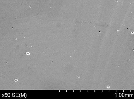
La composizione nominale della polvere è riportata in Tabella 1, mentre in Figura 1 è riportata una micrografia SEM, che mostra una geometria prevalentemente sferica, non esenta da irregolarità e presenza di satelliti.
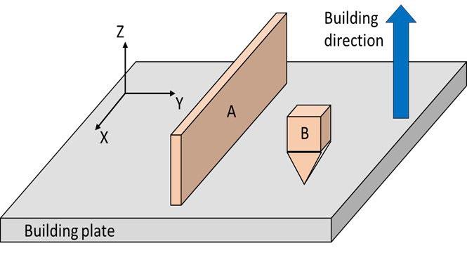
Sono stati realizzati dei provini, prismatici (8mmx8mmx10mm) per l’ottimizzazione dei parametri, mentre dei provini di forma allungata per le caratterizzazioni microstrutturali e meccaniche.
Le prove di L-PBF sono state eseguite con il sistema AM400 di Renishaw, operante con un laser in fibra pulsato di 400W di potenza, ed equipaggiato con un dispositivo per la riduzione del volume di stampa. Come piattaforma di stampa è stata utilizzata una piastra in AlSi10Mg.
Per lo studio del processo, sono stati presi in considerazione la potenza del fascio laser e il tempo di esposizione, mentre gli altri parametri di processo sono stati mantenuti costanti, su valori tipicamente utilizzati per le leghe di alluminio, come riportato in Tabella 2. Per la stampa si è inoltre utilizzata una strategia Meander, ed un angolo di rotazione di 67° della direzione di stampa tra uno strato ed il successivo. Il contenuto di O2 nell’atmosfera di processo è stato mantenuto al di sotto di 100 ppm.
La densità dei provini realizzati è stata misurata tramite il principio di Archimede, utilizzando una bilancia digitale di precisione, attrezzata allo scopo. Come densità di riferimento si è considerato il valore di 2.85 g/cm 3, riportato della scheda tecnica della polvere. Per quanto riguarda gli aspetti microstrutturali, le indagini sono state condotte con un FEG- SEM (SU70, by Hitachi), dotato di spettrometro EDX e sistema EBSD ((Ultradry EDX detector, Quasor detector e Pathfinder analysis system, Thermo Fisher).
Le analisi XRD sono state eseguite con il diffrattometro Panalytical X'Pert Pro, operante con la radiazione Cu Kα, nell’intervallo angolare 2theta di 20°–120°. Per queste analisi, i campioni sono stati sezionati lungo il piano X-Z, contenente direzione di costruzione, inglobati in resina conduttiva, preparati con lappatura alle carte e ai panni diamantati, ed infine lucidati con silice colloidale. Le analisi TEM ad alta risoluzione sono state condotte con il sistema FEI Titan3 G2 60-300, con tensione di ac-
celerazione di 300kV. Le micrografie sono state raccolte in campo scuro utilizzando due diversi rivelatori (annular dark field (ADF) e high angle annular dark field (HAADF) ), mentre le analisi composizionali sono state eseguite tramite EDX, utilizzando il detector FEI Super-X detector (Chemi-STEM technology). Per tali analisi, sono state ricavate sezioni sottili lungo il piano x-z, dapprima assottigliate meccanicamente fino a circa 50 – 80 µm e poi ulteriormente assottigliate, fino a perforazione tramite Plasma Ion Polishing, utilizzando il sistema Gatan - PIPS II, con fascio di Ar e porta campioni raffreddato con azoto liquido. Le prove meccaniche sono state eseguite su provini ad osso di cane di dimensioni ridotte, ricavate dai campioni allungati mediante elettroerosione, con una macchina di prova universale MTS Alliance RT/100, operando in accordo alla norma E8/E8M-11 ASTM. Preliminarmente le superfici dei provini sono state lucidate mediante carta abrasiva 600grit. Le prove sono state condotte con una
velocità di spostamento della traversa pari a 0.5 mm/min (3.3 10-4 s-1), a temperatura ambiente, in triplice copia.
RISULTATI E DISCUSSIONE Processabilità della lega.
Per valutare in maniera sintetica l’effetto dei due parametri di processo variati nella campagna sperimentale, ovvero
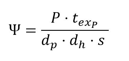
Potenza e tempo di esposizione del fascio laser, un parametro frequentemente utilizzato è la densità di energia, Ψ, che, per un sistema operante in condizioni pulsate può essere ricavata dalla formula seguente [15]:
dove P è la potenza del fascio laser, texp il tempo di esposizione, dp è la point distance, d h è l’ hatch spacing, ed s è lo spessore del layer.
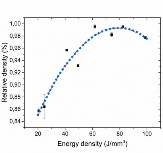
Variando i parametri descritti in tabella 2, è stato possibile individuare una finestra ottimale di valori, che ha consentito di raggiungere elevate densità relative (oltre il 99%), come riassunto nel grafico di Figura 2-a: valori ottimali di densità si sono ottenuti per densità di energia tra 60 e 85 J/mm3; con presenza di difetti molto limitata e di geometria tondeggiante associabile all’ intrappolamento di gas (figura 2-b).
Per valori di densità di energia inferiori a 60 J/mm3, si osserva la presenza di difetti di forma irregolare e di dimensioni superiori rispetto ai pori sferici (figura 2-c). Questi difetti dipendono dall’ apporto energetico troppo basso, per cui sono tipicamente associati ad una mancanza di fu-
sione [16-17]. Al contrario, per valori di densità di energia superiori a 85 J/mm3, ovvero oltre la finestra ottimale, si assiste ad una diminuzione dei valori di densità, associata a maggior presenza di porosità da gas; infatti, ad alte energie, si assiste ad un progressivo aumento della tendenza alla vaporizzazione di una parte del materiale allo stato liquido, che può quindi dar luogo a tale tipologia di difetti. Un andamento simile è stato riscontrato per molte leghe realizzate mediante L-PBF [18-20].
La condizione ottimale individuata nella presente sperimentazione è associata ad una densità di energia pari a 82 J/mm3, corrispondente alle condizioni di processo P=250 W; texp =80 µs. Tale valore di densità di energia è in linea con i valori ottenuti su altre leghe di alluminio contenti quantitativi analoghi di TiB2 [21-22], ma risulta maggiore dei valori in genere utilizzati per le leghe Al-Si.
Fig.2 - Evoluzione della densità relativa in fusione della densità di energia Ψ (a), e micrografie SEM relative a due campioni prodotti con densità di energia di 42 J/mm3 (b) e 82 J/mm3 (c) / Evolution of the relative density as function of energy density Ψ (a), SEM micrographs of the samples, produced at 42 J/mm3 (b) and 82 J/mm3 (c)
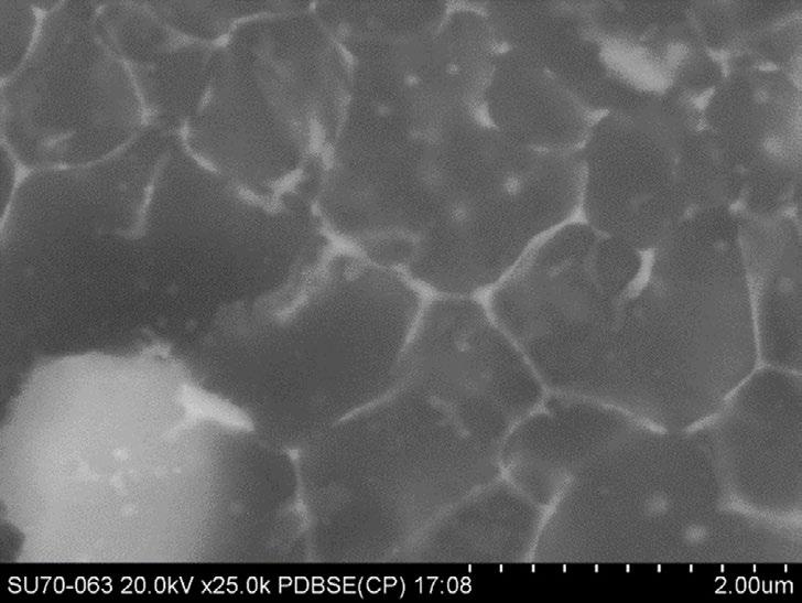
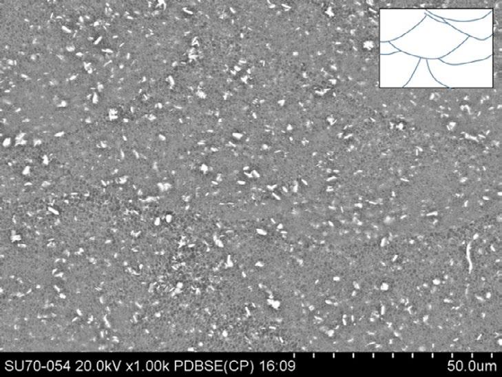
Caratterizzazione microstrutturale. Micrografie rappresentative della microstruttura della lega AlCu-TiB2 nelle condizioni as-built sono presentate in figura 3. In sezione x-z, è possibile notare il materiale si presenti pressochè omogeneo, formato da piccoli grani equiassici, di dimensioni inferiori ai 2 um, e uniforme dispersione di particelle di rinforzo. Si possono intravedere i bordi delle pozze fuse, individuabili nelle zone in cui si affiancano grani fini, nucleatisi all’interno della singola zona fusa in solidificazione, e grani più grandi appartenenti agli strati precedenti e coinvolti nella zona termicamente alterata della pozza in solidificazione. Per facilitarne l’individuazione, tali bordi sono stati schematizzati nell’inserto di figura 3-a. La forma appare semiellittica, con larghezza maggiore rispetto alla profondità; questa geometria è rappresentativa del profilo del cordone di saldatura in modalità di conduzione che si verifica quando la densità di potenza è inferiore a 106 W/cm2 [18]. Rapporti di forma larghezza/profondità maggiori di 1 indicano che il meccanismo prevalentemente è la fusione del materiale, senza significativi contributi di vaporizzazione sotto l’effetto del fascio laser. Questo risultato conferma che le condizioni di processo selezionate non inducono la formazione di key-hole, generalmente ottenibile solo con densità di potenza superiori a 106-107 W/cm2 .
L’osservazione attraverso segnale BSE consente di mettere inoltre in evidenza le particelle di TiB 2 (che appaiono più chiare della matrice) e degli elementi di lega ad alto
numero atomico (Ag, Cu). Le prime appaiono uniformemente distribuite; in particolare, non si osserva alcuna disposizione preferenziale rispetto alla sezione del melt pool (evidenziati nel riquadro di figura 3-a); ciò suggerisce che le alte velocità di raffreddamento promuovono l’intrappolamento delle particelle di rinforzo nel fronte di solidificazione, evitando pericolosi accumuli o segregazioni. La micrografia a più alti ingrandimenti, suggerisce inoltre la presenza di accumuli di elementi ad alto numero atomico (Cu e Ag) ai bordi dei grani equiassici, sia in forma soluta (aloni più chiari) che in forma di particelle (sagome ben definite).
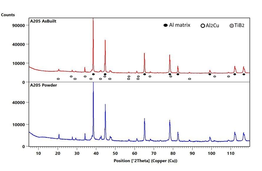
Le analisi XRD, i cui risultati sono presentati in figura 4, hanno consentito di verificare che sia nelle polveri di partenza che nei campioni as-built, sono presenti, oltre alla matrice di alluminio avente struttura cubica a facce centrate (face entered cubic, FCC), anche particelle di TiB2, con struttura esagonale compatta (hexagonal close packed, HCP) e, in minor misura, di Al2Cu Al2Cu , avente struttura tetragonale (body-centered tetragonal, BCT). Non solo la tipologia delle fasi presenti appare identica, ma anche le intensità relative dei picchi delle varie fasi, in particolare della matrice di alluminio sono pressochè identiche: ciò suggerisce l’assenza di una texture significativa nei campioni di AlCu-TiB2 prodotti mediante L-PBF con laser pulsato; viceversa, texture anche importanti sono spesso state osservate in altre leghe di alluminio prodotte con tecnica analoga [15].
evidenziare il confine del melt pool) e OIM, Orientation Image Maps relative alla matrice di alluminio, nelle tre direzioni del sistema di riferimento sistema. / EBSD analyses results in a region across a melt pool boundary; pattern quality map (with white dashed line highlighting melt pool boundary) and OIM of the aluminum matrix, related to three reference directions.
Per confermare quanto osservato attraverso le analisi XRD, sono state eseguite analisi EBSD. I risultati di un’analisi rappresentativa, condotta in una regione ai bordi di una pozza di fusione sono riportati in figura 5. Nella mappa
del pattern quality è delineato con una linea tratteggiata la posizione del bordo della pozza fusa: tale confine è individuabile solo grazie alla presenza dei grani accresciuti della zona termicamente alterata: non è possibile apprez-
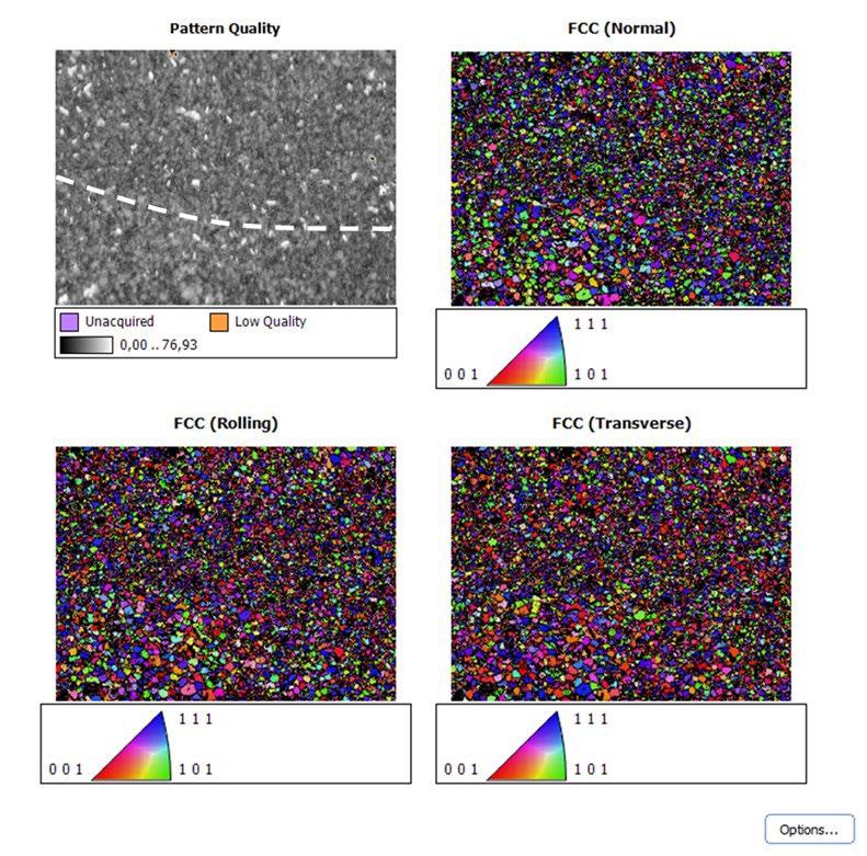
zare alcuna differenza in termini di orientazione o forma dei grani in tutta l’area. La mancanza di una orientazione preferenziale o di fenomeni di crescita epitassiale, anche localizzati, è messa in evidenza dalle tre altre figure, che rappresentano l’orientazione dei singoli grani rispetto alla direzione normale alla superficie del campione (Normal direction), e a due direzioni ortogonali contenute nel piano del campione (Rolling direction e Transverse direction), secondo la legenda cromatica riportata; indipendentemente dalla direzione presa come riferimento, le orientazioni dei grani appaiono assolutamente casuali, senza alcuna predominanza di un’orientazione (ovvero di un particolare colore). Inoltre, è stato possibile individuare anche grani di fase TiB2, (grani che appaiono bianchi nella Pattern quality map, ma non sono presenti nelle mappe OIM, riferite alla sola matrice di alluminio). Anche queste ultime non presentano alcuna orientazione preferenziale. La particolare microstruttura osservata, in termini di equiassicità e affinamento del grano può essere attribuita all’effetto della presenza delle particelle di TiB2, che favoriscono la nucleazione di grani all’interno del liquido, come ampiamente verificato nella pratica di fonderia [23] ma anche in processi additive quando nanoparticelle sono aggiunte alle polveri di processo [21, 24, 25]
Per meglio chiarire invece la presenza della fase Al2Cu ed in particolare la distribuzione degli elementi di fase all’interno dei campioni, si è reso necessario effettuare analisi al microscopio elettronico in trasmissione ad alta risolu-
zione, abbinate ad analisi EDX.
I risultati di tali investigazioni sono riportate nelle figure 6 e 7.
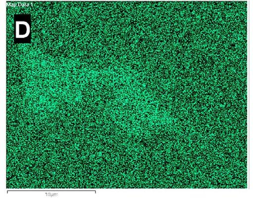
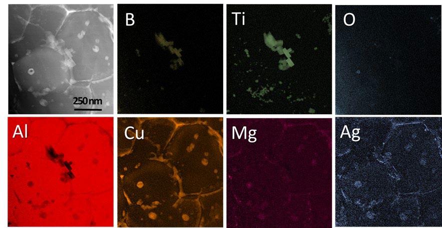
L’osservazione ad alta risoluzione ha consentito di verificare che TiB2 è presente con due distinte popolazioni: una popolazione micrometrica con a bastoncello, già osservata al microscopio elettronico a scansione, ma anche una popolazione nanometrica, di forma prismatica, presente sia all’interno dei grani, che in prossimità dei bordi grano, ove frequentemente sono stati osservati piccoli accumuli. Oltre alle particelle prismatiche di TiB2, è stato possibile osservare una folta presenza di altre particelle nanometriche, più tondeggianti, che l’analisi EDX ha messo in evidenza essere particelle di Al2Cu, con associate piccole quantità di Mg ed Ag, ed occasionali particelle di ossido. È stato quindi possibile confermare la presenza di Al2Cu, osservato attraverso le analisi XRD ma impossibile da indentificare al SEM.
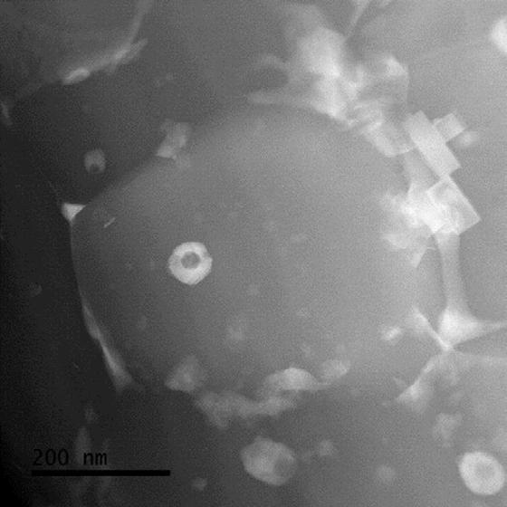
Inoltre, le mappe EDX effettuate al TEM, hanno consentito di evidenziare la presenza di Cu non solo come Al 2Cu, ma anche come alligante sia al centro dei grani, che in maggior quantità, segregato ai bordi grano. Tale risultato consente di ipotizzare che almeno potenzialmente sia possibile eseguire trattamenti di rafforzamento per precipitazione senza effettuare una preventiva solubilizzazione del materiale.
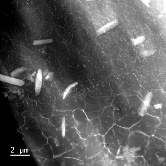
Fig.7 - Mappe EDX ottenute su campione as-built, per osservare la distribuzione degli elementi e la composizione delle nanoparticelle presenti. / EDX maps performed on as built specimen, to assess element distribution and nanometric phase composition.
Caratterizzazione meccanica
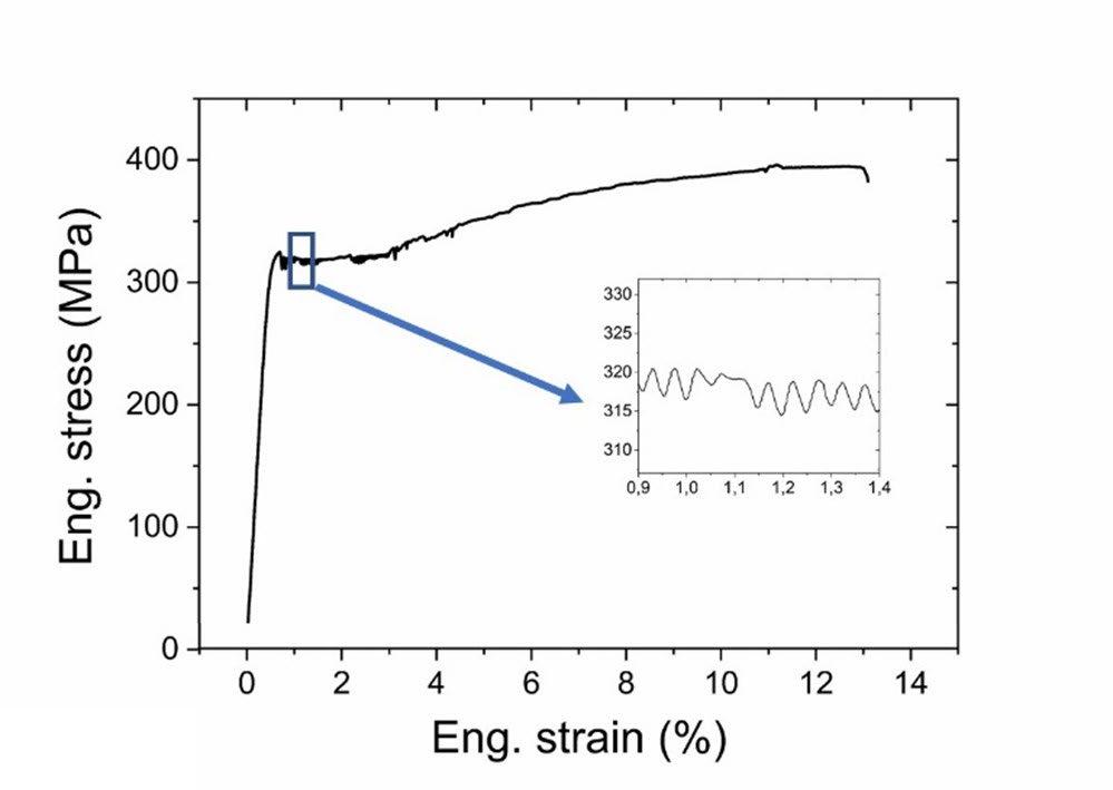
Per avere conferma della qualità dei provini ottenuti, si è provveduto anche ad una caratterizzazione meccanica su provini in scala ridotta. Un esempio dei risultati ottenuti è riportato in figura 8; sono stati ottenuti valori significativi sia di snervamento, che di carico a rottura ed allungamento a rottura (rispettivamente 317.8 ± 9.3 MPa, 391 ± 7.3 MPa and 12.5 ± 0.8 %). L’osservazione della forma della curva di trazione tuttavia evidenzia alcuni aspetti inattesi: infatti la curva presenta un punto di snervamento superiore, seguito da un plateau di deformazione a valori di carico quasi costanti, per poi proseguite, solo dopo il 3% circa di deformazione totale con un tratto di deformazione plastica con incrudimento. Inoltre la parte iniziale del tratto plastico appare caratterizzata da continue e frequenti oscillazioni del carico, comunemente identificate come effetto Portevin - Le Chatelier, ed osservate anche da altri autori [27]. Un comportamento simile è stato osservato anche in leghe di Ai contenenti Sc, prodotte mediante
L-PBF [26]. Confrontando i risultati ottenuti con quali di altre leghe prodotte per L-PBF [15], è possibile ipotizzare che tale comportamento sia associato all’interazione del moto delle dislocazioni con le nanoparticelle presenti nel materiale e con la presenza non omogenea di soluto, in particolare accumulato in prossimità dei bordi grano, che possono agire da punti di ancoraggio temporaneo delle dislocazioni, con conseguente aumento e diminuzione alternati del carico durante le prime fasi della deformazione plastica, fintanto che il moltiplicarsi delle dislocazioni e la loro interazione diretta non diviene predominante, con l’effetto macroscopico di un andamento più regolare della curva di trazione. Le già buone proprietà meccaniche osservate potrebbero quindi essere ulteriormente migliorate con opportuni trattamenti termici, che favoriscano l’evoluzione delle concentrazioni di soluto e delle nanoparticelle verso dimensioni e arrangiamenti più efficaci ai fini del rafforzamento della lega.
CONCLUSIONI
È stato possibile ottenere mediante Selective Laser Melting campioni con elevata densità e buone proprietà meccaniche di una lega di alluminio AlCu rinforzata con particelle di TiB2. Una prima campagna di ottimizzazione dei parametri di processo, effettuata su potenza del fascio e tempo di esposizione, ha consentito di individuare una finestra ottimale per il processo sufficientemente ampia, nella quale sono stati ottenuti campioni con densità elevata. All’interno di questa finestra, nelle condizioni ottimali di processo, è stato possibile raggiungere una densità del 99.5%.
Un’approfondita analisi microstrutturale è stata eseguita nella condizione ottimizzata, mediante HR-SEM abbinato ad analisi EBSD, ed analisi HR-TEM. La microstruttura rilevata si presenta uniforme, caratterizzata da grani fini ed equiassici, senza la presenza di crescita epitassiale, sovente riscontrata in metalli costruiti mediante processi di additive manufacturing. Le analisi ad alta risoluzione hanno inoltre consentito di analizzare la distribuzione e composizione delle seconde fasi presenti. Attenzione particolare è stata dedicata alla fase rinforzante TiB2, già
presente nelle polveri iniziali. Nei materiali processati mediante additive una doppia popolazione di tali particelle è stata osservata, una con dimensioni micrometriche ed una con dimensioni nanometriche. Non sono stati osservati effetti di segregazione di tali particelle a bordo grano, indicazione che le alte velocità di raffreddamento ne hanno promosso l’engulfment durante il processo di solidificazione. Viceversa, concentrazioni aumentate di Cu, Ag e Mg, presenti in lega sono state osservate in prossimità dei bordi grano e delle interfacce con la fase rinforzante. Tali segregazioni suggeriscono la possibilità di ulteriormente incrementare le proprietà meccaniche del materiale attraverso opportuni trattamenti termici.
RINGRAZIAMENTI
Gli autori ringraziano Nicola Bennato ed Enrico Bassani per il supporto tecnico nella realizzazione dei campioni e nella loro caratterizzazione. Le analisi HR-TEM sono state realizzate attraverso il programma di Short Term Mobility del CNR e finanziate attraverso il progetto Fact-Maps (grant agreement No 823717), nell’ambito di Horizon 2020 research and innovation program, – ESTEEM3.
BIBLIOGRAFIA
[1] J. Zhang, B. Song, Q. Wei, D. Bourell, Y. Shi, A review of selective laser melting of aluminum alloys: Processing, microstructure, property and developing trends, J. Mater. Sci. Technol. 35 (2019) 270–284. doi:10.1016/j.jmst.2018.09.004.
[2] Di Sabatino, M., Arnberg, L. Castability of aluminium alloys. Trans Indian Inst Met 62, 321–325 (2009). https://doi.org/10.1007/s12666009-0049-2.
[3] H. Zhang, H. Zhu, T. Qi, Z. Hu, X. Zeng, Selective laser melting of high strength Al – Cu – Mg alloys : Processing , microstructure and mechanical properties, Mater. Sci. Eng. A. 656 (2016) 47–54. doi:10.1016/j.msea.2015.12.101.
[4] X. Nie, H. Zhang, H. Zhu, Z. Hu, L. Ke, X. Zeng, Analysis of processing parameters and characteristics of selective laser melted high strength Al-Cu-Mg alloys : From single tracks to cubic samples, J. Mater. Process. Tech. 256 (2018) 69–77. doi:10.1016/j. jmatprotec.2018.01.030.
[5] A. Aversa, G. Marchese, A. Saboori, E. Bassini, D. Manfredi, S. Biamino, D. Ugues, P. Fino, M. Lombardi, New aluminum alloys specifically designed for laser powder bed fusion: A review, Materials (Basel). 12 (2019). doi:10.3390/ma12071007.
[6] R. Casati, M. Coduri, M. Riccio, A. Rizzi, M. Vedani, Development of a high strength Al–Zn–Si–Mg–Cu alloy for selective laser melting, J. Alloys Compd. 801 (2019) 243–253. doi:10.1016/j.jallcom.2019.06.123.
[7] J.H. Martin, B.D. Yahata, J.M. Hundley, J.A. Mayer, T.A. Schaedler, T.M. Pollock, 3D printing of high-strength aluminium alloys, Nat. Publ. Gr. (2017). doi:10.1038/nature23894.
[8] H. Zhang, H. Zhu, X. Nie, J. Yin, Z. Hu, X. Zeng, Effect of Zirconium addition on crack, microstructure and mechanical behavior of selective laser melted Al-Cu-Mg alloy, Scr. Mater. 134 (2017) 6–10. doi:10.1016/j.scriptamat.2017.02.036.
[9] A.B. Spierings, K. Dawson, T. Heeling, P.J. Uggowitzer, R. Schäublin, F. Palm, K. Wegener, Microstructural features of Sc- and Zrmodi fi ed Al-Mg alloys processed by selective laser melting, JMADE. 115 (2017) 52–63. doi:10.1016/j.matdes.2016.11.040.
[10] P. Wang, C. Gammer, F. Brenne, T. Niendorf, J. Eckert, S. Scudino, A heat treatable TiB2/Al-3.5Cu-1.5Mg-1Si composite fabricated by selective laser melting: Microstructure, heat treatment and mechanical properties, Compos. Part B Eng. 147 (2018) 162–168. doi:10.1016/j.compositesb.2018.04.026.
[11] https://www.cabiran.com/cwsd.php?Z3AuPTQ0MQ/NDA/ZWlmYm1rb3BjRWl-YHoicXd1.pdf
[12] https://www.aeromet.co.uk/a20x
[13] Xi L, Gu D, Guo S, Wang R, Ding K, Prashanth KG, Grain refinement in laser manufactured Al-based composites with TiB2 ceramic, J. Mater Res Technol 2020, 9-3, 2611-2622.
[14] J. Fiocchi, A. Tuissi, P. Bassani, C.A. Biffi, Low temperature annealing dedicated to AlSi10Mg selective laser melting products, Journal of Alloys and Compounds, DOI information: 10.1016/j.jallcom.2016.12.019. 695 (2017) 3402-3409.
[15] C.A. Biffi, J. Fiocchi, P. Bassani, A. Tuissi, Continuous wave vs pulsed wave laser emission in selective laser melting of AlSi10Mg parts with industrial optimized process parameters : Microstructure and mechanical behaviour, Addit. Manuf. 24 (2018) 639–646. doi:10.1016/j.addma.2018.10.021.
[16] Zhang, B., Li, Y. & Bai, Q. Defect Formation Mechanisms in Selective Laser Melting: A Review. Chin. J. Mech. Eng. 30, 515–527 (2017). https://doi.org/10.1007/s10033-017-0121-5
[17] Wayne E. King, Holly D. Barth, Victor M. Castillo, Gilbert F. Gallegos, John W. Gibbs, Douglas E. Hahn, Chandrika Kamath, Alexander M. Rubenchik, Observation of keyhole-mode laser melting in laser powder-bed fusion additive manufacturing, Journal of Materials Processing Technology, Volume 214, Issue 12, 2014, Pages 2915-2925, https://doi.org/10.1016/j.jmatprotec.2014.06.005.
[18] Fiocchi, J., Biffi, C.A., Tuissi, A., Selective laser melting of high-strength primary AlSi9Cu3 alloy: Processability, microstructure, and mechanical properties, Mater Des 191, 108581 (2019)
[19] Biffi, C.A., Fiocchi, J., Valenza F. Bassani P, Tuissi, A., Selective Laser Melting of NiTi Shape Memory Alloy: Processability, Microstructure, and Superelasticity, Shape Memory and Superelasticity, 2020, 6(3), pp. 342-353.
[20] CA Biffi, AG Demir, M Coduri, B Previtali, A Tuissi, Laves phases in selective laser melted TiCr1.78 alloys for hydrogen storage, Materials Letters, 2018, doi: 10.1016/j.matlet.2018.05.028
[21] Zhou SY, Su Y, Wang H, Enz J, Ebel T, Yan M, Selective laser melting additive manufacturing of 7xxx series Al-Zn-Mg-Cu alloy: cracking elimination by co-incorporation of Si and TiB2, Additive Manufacturing 36 (2020) 101458.
[22] X.P. Li, G. Ji, Z. Chen, A. Addad, Y. Wu, H.W. Wang, J. Vleugels, J. Van Humbeeck, J.P. Kruth. Selective laser melting of nano-TiB2 decorated AlSI10Mg alloy with high fracture strength and ductility. Acta Mater. 29 (2017) 183-193
[23] H. Choi, W.-H. Cho, H. Konishi, S. Kou, X. Li. Nanoparticle-induced superior hot tearing resistance of A206 alloy. Metall. Mater. Trans. 44A, (2013) 1897-1907.
[24] X. Zhon, Z. An, Z. Shen, W. Liu, C. Yao. Particle control in selective laser melting in-situ oxide dispersion strengthened method. OP Conf. Ser. Mater Sci. Eng. 167 (2017) 012048
[25] P. Yuan, D. Gu, D. Dai. Particulate migration behavior and its mechanism durng selective laser melting of TiC reinforced Al matrix nanocomposites. Mater. Design 82 (2015) 46-55.
[26] Jia Q, Rometsch P, Cao S, Zhang K, Wu X. Towards a high strength aluminium alloy development methodology for selective laser melting. Mater Des 2019;174:107775.
[27] Mair P, Kaserer L, Braun J, Weinberger N, Letofsky-Papst I, Leichtfried G. Microstructure and mechanical properties of a TiB2-modified Al–Cu alloy processed by laser powder-bed fusion. Mater Sci Eng A 2021;799. https://doi.org/10.1016/j.msea.2020.140209.
Processability, microstructure and mechanical properties of AlCu-TiB2 alloy produced by Selective Laser Melting
The present work explores the microstructure and the mechanical properties of a TiB2 reinforced AlCu alloy, a composite material developer for advanced applications. The material was processed by Selective Laser Melting, by using a Pulsed Laser source. Optimization of process parameters led to a maximum density of 99.5%. The microstructure of specimens produces with optimized conditions was deeply characterized. Fine and equiaxed grains were found, without any epitaxial growth, that was observed in many additive manufactured metals. TiB 2, that were present as micrometric and nanometric particles, were found evenly dispersed in the matrix; the high cooling rates experienced by the material during the process favored their engulfment during solidification. On the other side, Cu, Ag and Mg segregations were observed at grain boundary and at interfaces with TiB2 particles.
KEYWORDS:


Analisi e contronto di strutture reticolari mediante processi additivi a deposizione
a cura di: V. Di Pompeo, A. Santoni, M.L. Gatto, E. Santecchia, M. CabibboLa produzione additiva di parti in materiale metallico sta entrando sempre più nel paradigma di produzione aziendale offrendo componenti sempre più performanti e in grado di rispondere alle esigenze di mercato. Spesso le aziende utilizzano processi additivi ampiamente conosciuti come la powder bed fusion (PBF) o la direct energy deposition (DED). Tuttavia, i costruttori di macchine stanno cercando di offrire soluzioni più accessibili come ad esempio la tecnologia di material extrusion (ME). Questo innovativo processo permette di realizzare parti in materiale inizialmente composito cioè formato da polvere metallica e materiale termoplastico per poi, attraverso successivi trattamenti termici in fornace, si ottengono le parti in materiale metallico. Il presente articolo ha l’obiettivo di dimostrare la fattibilità realizzativa di una struttura auxetica quantificandone la presenza di vuoti. Per poi confrontare, i risultati ottenuti da una prova di trazione svolta: sia su un classico provino di trazione che su una struttura auxetica e risalire alla modalità di frattura.
PAROLE CHIAVE: MATERIAL EXTRUSION, 316L, STRUTTURE RETICOLARI, STRUTTURE AUXETICHE, PROVE DI TRAZIONE, ANALISI DELLA FRATTURA, FRATTURA DUTTILE, ANALISI DEI VUOTI, SINTERIZZAZIONE, TRATTAMENTI TERMICI
INTRODUZIONE
Negli ultimi anni, le tecnologie di Additive Manufacturing (AM) hanno rivoluzionato il modo di fabbricare i prodotti in molti settori industriali, come l’automotive, l’aeronautico e il biomedico. Esse permettono di produrre direttamente dai progetti CAD parti tridimensionali e di geometria complessa, anche con strutture complicate, che sarebbero estremamente difficili da produrre con le tecniche di manifattura tradizionale [1]. Attualmente, esistono molteplici tecnologie additive in grado di creare componenti metallici complessi. I più diffusi sono la powder bed fusion (PBF) in cui la polvere viene fusa mediante un laser o fascio di elettroni o la direct energy deposition (DED) in cui la polvere o un filamento vengono estrusi attraverso un ugello per poi essere fusa mediante un laser. Al di là delle più note tecnologie descritte in precedenza, sempre più aziende stanno cercando di proporre sul mercato tecnologie meno costose e più semplici da utilizzare. Un esempio è la tecnologia di Material Extrusion (ME) proposta da Desktop Metal, in cui la parte viene realizzata estrudendo un materiale composito formato da polvere metallica inglobata all’interno di un legante in cera e materiale termoplastico. Successivamente la parte viene inserita all’interno di una fornace che è in
grado di far evaporare termicamente il materiale plastico e conservare la polvere metallica parzialmente legata con la cera, per poi subire il processo di sinterizzazione con l’eliminazione del legante residuo e la creazione della parte metallica [2]. Attraverso questa tecnologia è possibile realizzare parti con un elevata complessità geometrica in un ambiente potenzialmente salubre, poichè la deposizione della polvere metallica è inglobata all’interno del legante e quindi meno volatile e pericolosa. Con la diffusione delle tecniche additive, il portfolio dei materiali disponibili è aumentato notevolmente, in particolar modo per gli acciai inossidabili. Uno dei materiali più utilizzati è l’AISI 316L, un acciaio inox austenitico molto versatile e comune, caratterizzato dalla presenza del Molibdeno.
I casi studio più utilizzati per evidenziare le caratteristiche della produzione additiva riguardano la realizzazione di strutture reticolati poiché risultano essere estremamente complicate da realizzare con le tecnologie tradizionali, sia dal punto di vista economico che da quello del time to market. Infatti, queste parti presentano variazioni di spessore e riempimenti parziali dell’oggetto che ne ostacolano la realizzazione attraverso tecniche convenzionali [3]. Nel corso degli anni queste strutture sono state ideate e utilizzate nel settore aerospaziale dove la leggerezza è uno dei vincoli progettuali più stringenti per il dimensionamento dei componenti [4]. Nello specifico, le strutture reticolari vengono impiegate per ridurre il peso e migliorare le resistenze meccaniche specifiche [5]. Con la diffusione delle
tecnologie additive, le strutture reticolari hanno visto un aumento dell’impiego in settori come quello biomedicale, automotive e civile [6]. Infatti, in precedenza, i componenti con elevata complessità geometrica non venivano realizzati a causa dell’assenza di sistemi produttivi in grado di mantenere i costi accessibili [7]. Inoltre, grazie alla flessibilità delle tecniche additive, si è riusciti a creare strutture reticolari complesse modificandone il paradigma, poiché si è riusciti ad ottenere geometrie in grado di far variare le proprie caratteristiche meccaniche nel tempo se sollecitate. La struttura auxetica è uno degli esempi più noti in cui si ha un coefficiente di Poisson negativo che varia nel tempo , se il materiale è sollecitato meccanicamente [8]. Tale fenomeno ha portato alla diffusione di queste strutture in molteplici settori, tra cui quello dell’edilizia come elementi smorzanti per la protezione sismica o come strutture da costruzione tolleranti al danno [9]. Il presente lavoro si poneva l’obiettivo di valutare la realizzabilità di strutture reticolari auxetiche attraverso tecniche di ME e di dimostrarne il corretto comportamento meccanico se sottoposte a trazione.
MATERIALI E METODI
La polvere utilizzata per il processo di ME è l’acciaio inox AISI 316L. Il materiale metallico è inglobato all’interno di un materiale termoplastico in grado di facilitare il processo di deposizione. In Tabella 1, la composizione chimica (wt%) fornita da Desktop Metal:
I provini di trazione realizzati non presentano intagli in quanto il materiale e il processo di stampa generano un intensificazioni delle tensioni nella stessa zona (vedi Fig. 1).
Le strutture reticolari prese in considerazione sono delle strutture auxetiche che presentano le variabili realizza-
tive (s, φ, a e h) riportate in Tab. 1. La variazione di tali parametri permette di ottenere delle strutture differenti confrontabili al fine di ottenere le caratteristiche meccaniche ottimali.
I due provini sono stati realizzati mediante la stampante Desktop Metal Studio System mentre i parametri di processo utilizzati nella stampante sono riportati in Tab. 3.
Una volta stampati, i componenti sono realizzati in materiale composito dove il metallo, in polvere, è inglobato all’interno di una matrice termoplastica. Al fine di eliminare il materiale superfluo, le parti vengono inserite all’interno di una fornace e trattate termicamente. Nello specifico, viene effettuato dapprima il debinding, in cui la parte viene riscaldata a circa 500°C per 2h e il materiale plastico viene eliminato. Dopo aver eliminato il legante, la parte che è composta da polvere metallica e binder residuo vie-
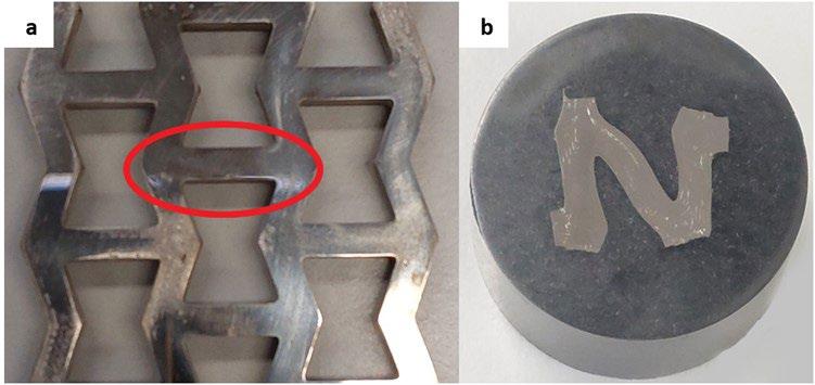
ne sinterizzata a circa 1370°C ottenendo così la parte finita e ben stabilizzata a livello microstrutturale. I due processi appena descritti avvengono sottovuoto e in ambiente inerte con gas composto dal 97% di Argon e 3% di idrogeno. Inoltre, le parti da trattare in fornace vengono inseriti all’interno di un “Retort” in carbonio puro riportato in Fig. 2 che ha lo scopo di creare un volume a temperatura stabile per evitare gradienti termici e il danneggiamento delle parti.
Per le prove di trazione è stata utilizzata una macchina MTS 810, con una forza massima applicata pari a 250 KN e una velocità di avanzamento di 0.1 mm/min. Una volta che il provino con struttura auxetica è stato sottoposto a trazione, una cella è stata inglobata con della resina fenolica (Fig. 3) e analizzata sia al microscopio ottico che al microscopio elettronico a scansione (SEM). Per
l’analisi delle superfici e delle porosità è stato utilizzato un microscopio ottico Leica DMi8 mentre per le analisi della frattura è stato utilizzato un microscopio elettronico a scansione (FEG-SEM) Tescan Vega 3. Infine, per la quantificazione dei vuoti presenti nel materiale sono state utilizzate 10 immagini per campione e calcolate attraverso ImageJ.
RISULTATI SPERIMENTALI E DISCUSSIONE
La norma ASTM-E8 specifica che i test di trazione devono essere fatti su provini ad osso di cane con intaglio tra l’afferraggio e il tratto utile [11]. I primi test svolti hanno portato ad uno scorretto comportamento meccanico delle strutture auxetiche. Infatti, i provini hanno subito il carico esclusivamente nella zona dell’intaglio e i risultati dei test condotti hanno portato a rilevare la classica curva di un provino di trazione. In Fig. 4 è possibile osservare il comportamento errato della struttura con distacco di materiale nella zona dell’intaglio. Inoltre, si può con-
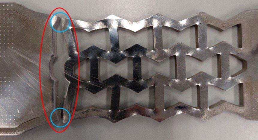
statare che le strutture non hanno subito deformazione proprio perché lo sforzo si è concentrato localmente in quel solo punto. Dalla stessa foto si può notare come il distacco sia stato netto in corrispondenza della zona di contorno mentre nella zona di infill, cioè nei due tratti esterni cerchiati in blu, la rottura sia progressiva evidenziando un comportamento plastico. È evidente dalle immagini che la zona centrale ha subito il distacco immediatamente dopo l’inizio del tratto plastico mentre i due tratti laterali abbiano subito il carico durante tutta la prova per poi rompersi.
Individuati i problemi, il provino è stato riprogettato senza l’intaglio. Dalla Fig. 5 si può notare il corretto comportamento della struttura dopo la riprogettazione. Nello stesso grafico è rappresentato una curva di tensione-deformazione di una classica prova di trazione in nero e in rosso di un provino avente come riempimento le strutture auxetiche. Facendo un confronto tra le due curve si può osservare che il Modulo di Young è lo stesso, infatti, il primo tratto di curva cioè il tratto elastico si sovrappone. A meno di differenze in termini di valore assoluto, le due curve hanno un andamento identico, salvo poi variare nel tratto plastico. Infatti, nel tratto comunemente associato alla strizione la struttura auxetica presenta dei tratti verticali con cali di tensione e successivamente tratti in cui la tensione riaumenta con rapidi aumenti di
deformazione. Tale comportamento è tipico delle strutture auxetiche in cui il calo di tensione avviene quando c’è la variazione di forma della struttura fino ad arrivare ad una posizione di equilibrio in cui la resistenza del provino aumenta con conseguente aumento della tensione. Questo scalini di tensione e deformazione si ripetono per 5 volte fino ad arrivare alla rottura del materiale.
questo caso, se si volesse fare un paragone sulle performance dei due provini bisognerebbe dividere la forza calcolata per il peso e calcolare la forza specifica. L’elevato rapporto resistenza-peso è una delle caratteristiche peculiari delle strutture reticolari.
Tab.3 - Valori sulle prove di trazione / Tensile test values
facendo rimanere esclusivamente la polvere metallica per poi sinterizzarla a temperature ancora più alte e sottovuoto. È chiaro come la sinterizzazione della polvere e l’applicazione del vuoto non possono compensare totalmente l’eliminazione del binder che varia dal 18% al 22% in volume e di conseguenza si generano porosità su entrambi i provini per un valore pari al 4%.
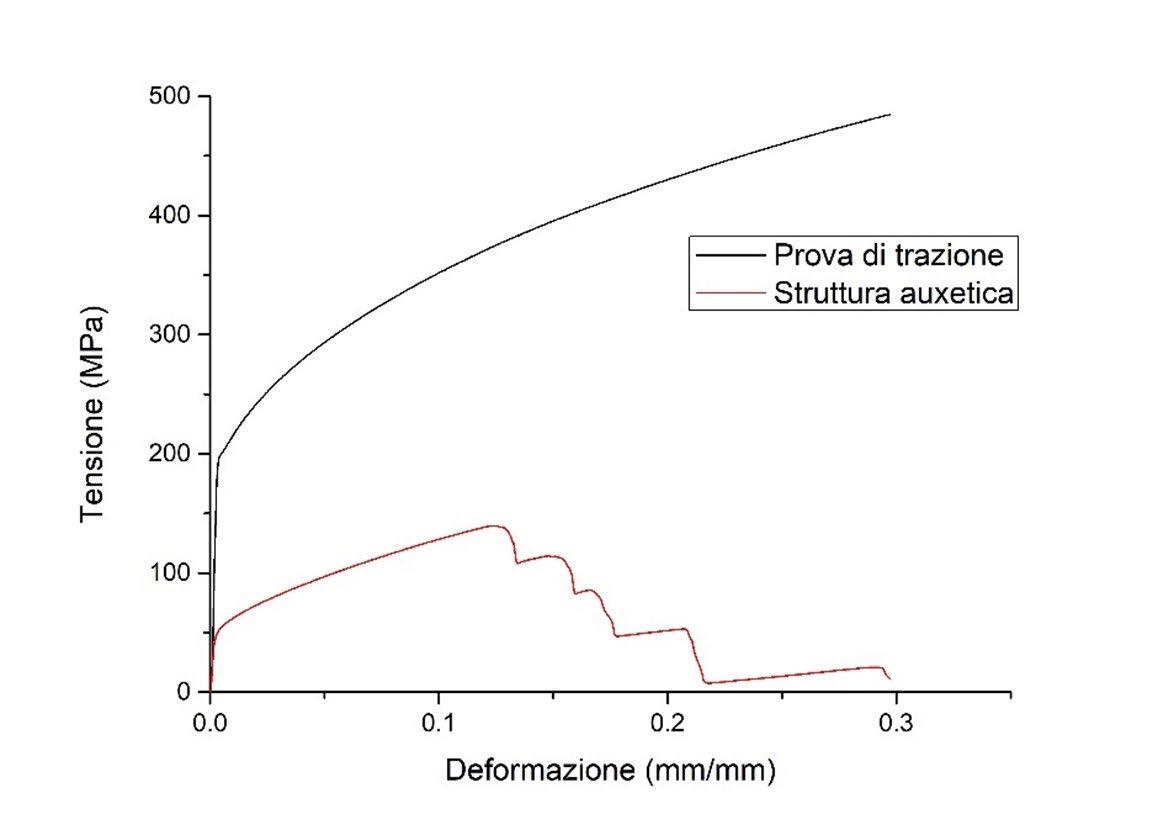
Dopo aver completato la prova di trazione, il provino è stato osservato al SEM per analizzare la modalità di frattura. Dalla Figura 7(a) si può osservare come il provino nella zona di frattura sia pieno di porosità, risultato che conferma quanto osservato al microscopio ottico. Queste porosità, oltre a ridurre la densità del materiale,
facilitano la propagazione della cricca abbassando le caratteristiche meccaniche complessive del provino. Dalla Fig. 7(b) si può osservare come la superficie di frattura mostri la tipica morfologia di una rottura di natura duttile, con dimples di dimensioni variabili [12].
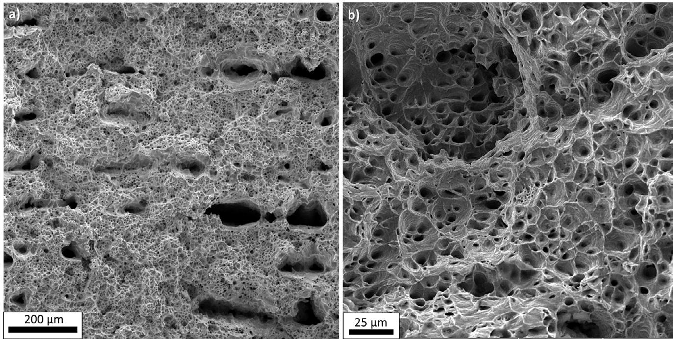
CONCLUSIONI
Attraverso la tecnologia di ME è possibile realizzare strutture reticolari come nelle altre tecnologie additive più note. Questa tecnologia, però, si differenzia dalle altre per la facilità di utilizzo e la facile gestione delle polveri. Di contro, presenta ancora delle limitazioni in termini di densità del materiale con alte porosità e caratteristiche meccaniche inferiori. Dallo stato dell’arte si evince come la struttura analizzata
presenta il classico comportamento delle strutture auxetiche con i gradini orizzontali che si generano nel tratto plastico. Tale fenomeno potrà essere utilizzato per applicazioni in cui si ha bisogno di buone resistenze meccaniche specifiche e deformazioni evidenti in previsione di una possibile rottura.
In futuro, si prevede di ampliare il lavoro attraverso:
• La realizzazione di un design of experiment (DOE) facendo variare i parametri delle strutture
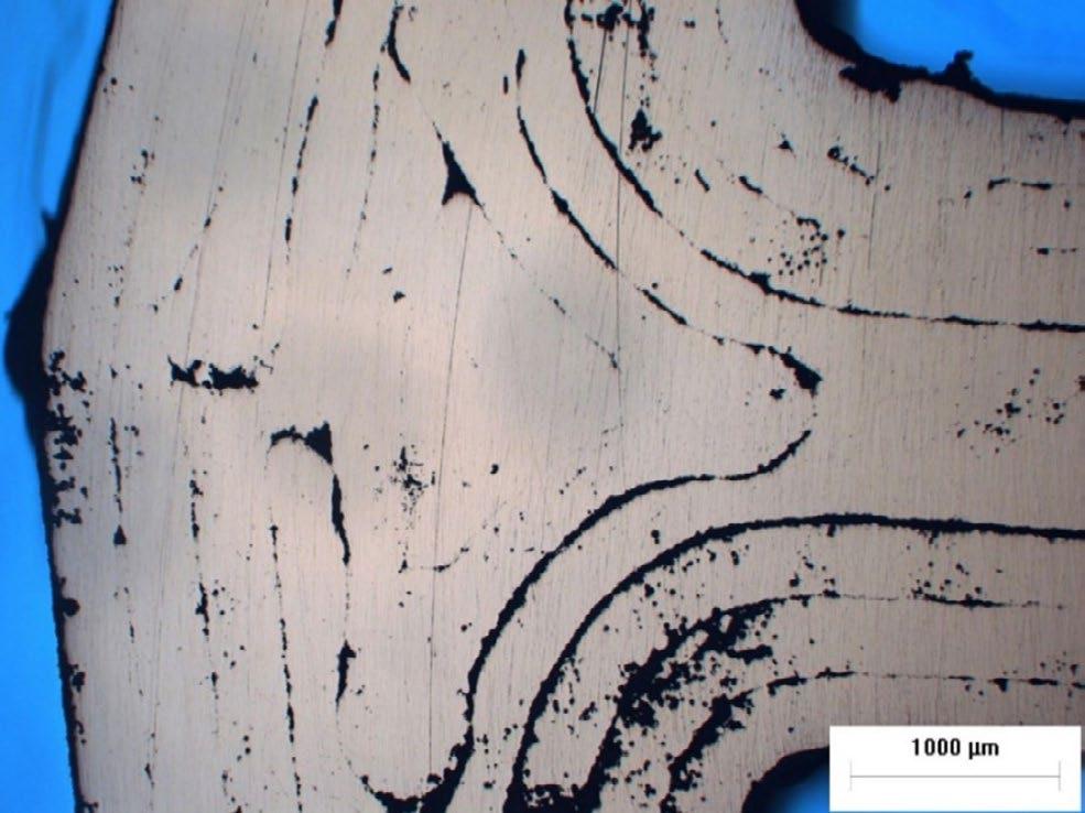
auxetiche;
• Le prove di trazione per individuare il miglior comportamento meccanico specifico in funzione dei parametri variati;
• L’analisi dei campioni per individuare il fenomeno di frattura associato;
• L’analisi della microstruttura prima e dopo la rottura
BIBLIOGRAFIA
per individuare eventuali deformazioni microstrutturali.
RINGRAZIAMENTI
Questa ricerca è stata finanziata parzialmente attraverso il progetto Dipartimento di Eccellenza, MIUR-Italy (ARTI-COLO 1, COMMI 314–337 LEGGE 232/2016)
[1] Gabilondo M, Cearsolo X, Arrue M, Castro F. Influence of Build Orientation, Chamber Temperature and Infill Pattern on Mechanical Properties of 316L Parts Manufactured by Bound Metal Deposition. Materials (Basel) 2022.
[2] Di Pompeo V, Santoni A, Santecchia E, Spigarelli S. On the Short-Term Creep Response at 482 °C (900 °F) of the 17-4PH Steel Produced by Bound Metal Deposition. Metals (Basel) 2022.
[3] Parenti P, Puccio D, Colosimo BM, Semeraro Q. A new solution for assessing the printability of 17-4 PH gyroids produced via extrusion-based metal AM. J Manuf Process 2022.
[4] Di Pompeo V, Forcellese A, Mancia T, Simoncini M, Vita A. Effect of Geometric Parameters and Moisture Content on the Mechanical Performances of 3D-Printed Isogrid Structures in Short Carbon Fiber-Reinforced Polyamide. J Mater Eng Perform 2021.
[5] Hunt CJ, Morabito F, Grace C, Zhao Y, Woods BKS. A review of composite lattice structures. Compos Struct 2022.
[6] Forcellese A, Simoncini M, Vita A, Di Pompeo V. 3D printing and testing of composite isogrid structures. Int J Adv Manuf Technol 2020.
[7] Kaur I, Singh P. Critical evaluation of additively manufactured metal lattices for viability in advanced heat exchangers. Int J Heat Mass Transf 2021.
[8] Wang XT, Wang B, Li XW, Ma L. Mechanical properties of 3D re-entrant auxetic cellular structures. Int J Mech Sci 2017.
[9] Maran S, Masters IG, Gibbons GJ. Additive manufacture of 3d auxetic structures by laser powder bed fusion—design influence on manufacturing accuracy and mechanical properties. Appl Sci 2020.
[10] www.desktopmetal.com
[11] ASTM E8. ASTM E8/E8M standard test methods for tension testing of metallic materials 1. Annu B ASTM Stand 4 2010.
[12] Pan X, Qian G, Hong Y. Nanograin formation in dimple ridges due to local severe-plastic-deformation during ductile fracture. Scr Mater 2021.
Analysis and comparison of lattice structure realized by material extrusion process
Nowadays, the metal additive manufacturing process are employing in many companies to produce high performance parts able to react the market request. Many companies are using more well known metal additive manufacturing technologies such as powder bed fusion and directed energy deposition. However, other accessible technologies are arising such as the material extrusion (ME) process. This technology realizes parts from a composite material based on metal powder and thermoplastic binder to final metal parts by heat post-processing treatments. The aim of this document is to demonstrate the feasibility to print the auxetic structures by material extrusion and quantify the voids content. Furthermore, the tensile tests are conducted to the tensile and auxetic samples to compare the results and analysed the fractural mode.
KEYWORDS: MATERIAL EXTRUSION, 316L, LATTICE STRUCTURE, AUXETIC STRUCTURE, TENSILE TEST, FRACTURE ANALYSIS, DUCTILE FRACTURE, VOIDS ANALYSIS, SINTERING, HEAT TREATMENT
The effects of heat treatment on microstructure evolution of 17-4 PH single tracks deposited by AM-DED
edited by: C. Morales, M. Merlin, F. Debdoubi, A. Fortini, P. FerrucciDirect Energy Deposition (DED) is an additive manufacturing technique that has received increasing attention from several industrial fields to produce near-net-shape parts, for repairing components or applying hard-facing coatings. In this context, the 17-4 PH stainless steel is an attractive material because it combines good corrosion resistance with high toughness and strength. In the present work, the effects of post-building heat treatment routes applied to 17-4 PH single tracks deposited by DED on an AISI 316L plate were investigated and preliminary results are shown. Optical microscopy was used to study the effects of solubilization and different aging times on the microstructure, focusing on the amount of δ ferrite inside the tracks. Moreover, Vickers microhardness tests were performed to analyze the evolution of hardness across the substrate/track interface.
KEYWORDS: 17-4 PH, DIRECT ENERGY DEPOSITION, HEAT TREATMENT, MICROSTRUCTURE, MICROHARDNESS
INTRODUCTION
Direct Energy Deposition (DED) is one of the most promising additive manufacturing (AM) techniques that has been widely used in the last years for printing complex metallic parts, but also for repairing components or applying hard-facing coatings [1–4]. By means of a focused heat source, typically a laser, the metal is melted simultaneously as it is deposited, and the subsequent rapid solidification promotes peculiar microstructures affecting morphology and distribution of phases with respect to the typical microstructure obtained with casting or other more traditional manufacturing processes. In metal additive manufacturing, the 17-4 PH stainless steel is one of the most used because of its fascinating properties, such as high strength, toughness and corrosion resistance [5–8]. It is well-known that the interesting mix of its properties needs to be generally optimized by means of a precipitation hardening treatment so, also dealing with additive manufacturing techniques, a post-processing procedure is usually necessary in order to improve both the microstructural and mechanical behavior of the steel. Different authors dealt with the improvement of the 17-4 PH mechanical properties by studying the microstructure of samples fabricated via Selective Laser Melting (SLM) or in general
University
* mattia.merlin@unife.it
Powder Bed Fusion (PBF) techniques. Only in a few studies the effect of post-processing heat treatments was investigated, such as in the work of Sun et al. who found that the usual H900 heat treatment performed on 17-4 PH SLMed specimens is able to guarantee values of hardness higher than the ones achieved on 17-4 PH wrought products [9]. Similarly, Cheruvathur et al. highlighted that a homogenization heat treatment carried out at 1150 °C improves the quantity of martensite in 17-4 PH samples produced via AM, reducing the retained austenite with respect to the as-built condition [9]. Several other studies focused on the application of different heat treatment routes on 17-4 PH 3D printed samples correlating their microstructure with the mechanical behavior [10-15]. Nevertheless, to the knowledge of the authors, the analysis of both microstructure and mechanical properties of the 17-4 PH steel processed by DED and thermally treated has not been deeply studied in the literature. Mathoho et al. compared the microstructure and hardness of 17-4 PH DED samples in both as-built and post-process heattreated conditions [12]. In the present investigation, two different heat treatment routes concerning both solubilization and different aging times are studied to analyze their effect on the microstructure as well as on the hardness of 17-4 PH single tracks deposited by DED onto an AISI 316L stainless steel.
MATERIALS AND METHODS
Three 100 mm long single tracks were deposited over a 120 x 40 x 10 mm AISI 316L substrate (Fig. 1a) via DED by means of a six-axis AMM IRB 4600 robot, just as shown in Fig. 1b. The process parameters used during the deposition are depicted in Tab.1. To perform the analyses presented in this work, three samples from tracks named A and C were drawn at the same distance from the initial point of the tracks in the zone depicted with green diamonds in Fig. 1b; the samples were named A1, A2 and A3 for track A and C1, C2 and C3 for track C (see Fig. 1a). Samples A1 and C1 were used to characterize the material in the as-built condition, while the other samples were subjected to two different heat treatment routes. The first heat treatment route (HT1), performed on samples A2 and A3, was a modification of the conventional H900 treatment specified for the 17-4 PH steel in the
ASTM A693-0; in particular, it involved a solubilization performed at 1040 °C for 30 min, quenching in water and two different aging at 480 °C for 60 min (HT1_60) and 300 min (HT1_300). The second heat treatment route (HT2) was performed on samples C2 and C3, and consisted of a shorter solubilization performed at 1040 °C, quenching in water, and the same aforementioned agings at 480 °C for 60 min (HT2_60) and 300 min (HT2_300). In Tab. 2 are summarized the investigated conditions. The solubilization heat treatment was performed on a tubular Lenton LTF oven while a Remet mod. E-79N oven was used for aging. During the treatments, a K-type thermocouple was positioned inside the equipment and the temperature evolution was monitored and acquired by an Omega TC-08 data logger with PicoLog 6 software. Samples in the as-built condition (A1, C1) and after heat treatments (A2, A3, C2, C3) were prepared for microstructural investigation according to standard metallographic procedures. The samples were etched with the Kalling’s solution (1.5 g CuCl2, 33 ml HCl, 33 ml ethanol, and 33 ml of water) for 14 s in order to study the microstructural evolution of the 17-4 PH deposited tracks according to the heat treatment parameters via a Leica Dmi8A optical microscope. Moreover, Vickers microhardness profiles were carried out on all the samples across the substrate, the interface and the deposition track by means of a Future-Tech FM1e micro indenter using a 50 kgf load in accordance with the UNI EN ISO 6507 standard.
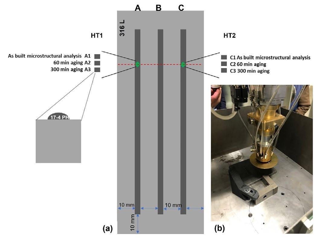
RESULTS AND DISCUSSION
In Fig. 2 the typical microstructure of the deposited track is shown, revealing a martensitic matrix with the presence of a lathy δ -ferrite mainly localized at the interface between the deposition clad and the substrate (red blow-up). Islands of interdendritic δ -ferrite were also detected inside the clad, as it can be noted in the light
blue blow-up of the same figure. A decrease in δ -ferrite content was observed moving from the interface to the top of the deposition track, in good agreement with some studies [12,16,17] but also in accordance with the thermal gradients and the high cooling rates experienced by the material during the deposition process.
Deep microstructural analyses were also performed after the heat treatments. Analyzing the microstructure of samples A2 and A3, some peculiar differences were noted with respect to the as-built condition (see Fig. 3). In both samples, the 30 min of holding time at the austenitization temperature (HT1) was sufficient to guarantee the
formation of highly homogenized martensite after quenching. These heat treatment parameters promoted the dissolution of the δ -ferrite. Despite the shorter solubilization time (HT2), no traces of δ -ferrite were evenly detected in samples C2 and C3 (see Fig. 4).
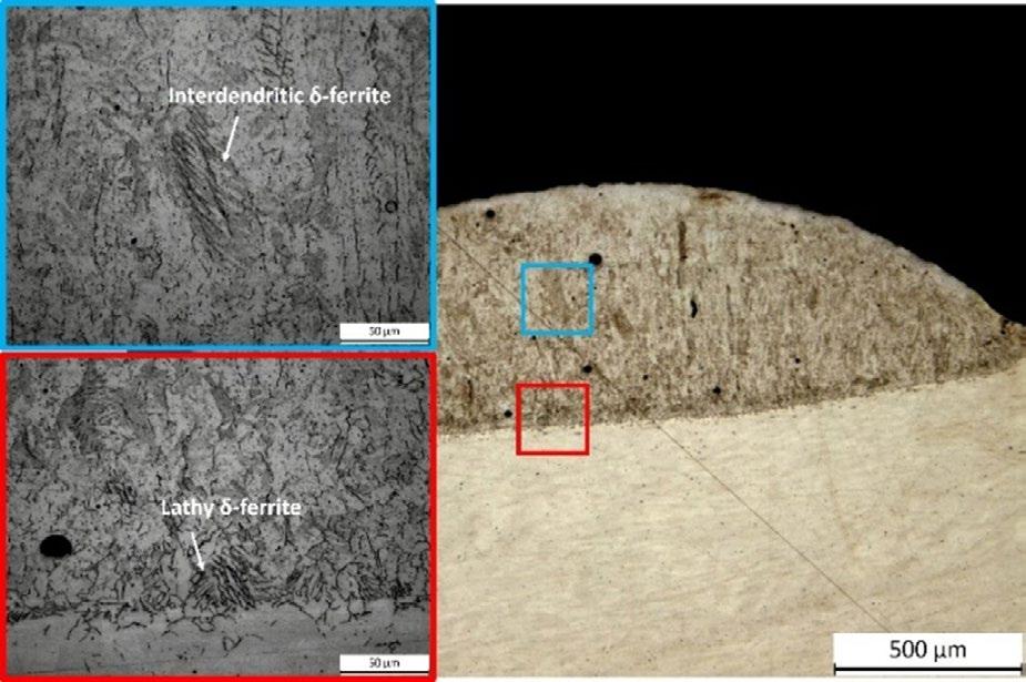
Microhardness tests were also performed in order to study the efficacy of possible heat treatment routes in enhancing the mechanical properties of the 17-4 PH deposited by DED. A mean hardness of 385 ± 3 HV0.05 was measured for the 17-4 PH steel inside the clad in the as-built condition. In Fig. 5 are depicted the relevant microhardness profiles performed across the substrate/ track interface of the heat-treated samples. Considering the mean values of hardness from the bottom to the top of the track, a significant increase in hardness of more than 100 HV0.05 was obtained in samples A2 and A3 with respect to the as-built condition. The duration of austenitization was sufficient to solubilize
all the elements useful for the subsequent precipitation hardening that occurred during aging; 60 min of aging (HT1_60) is long enough to maximize the hardness of the material. Conversely, the shorter solubilization applied to samples C2 and C3 was not able to induce the same increase in hardness in 60 min (HT2_60); in this case, the material needs more aging time to gain the maximum increase in hardness (HT2_300).
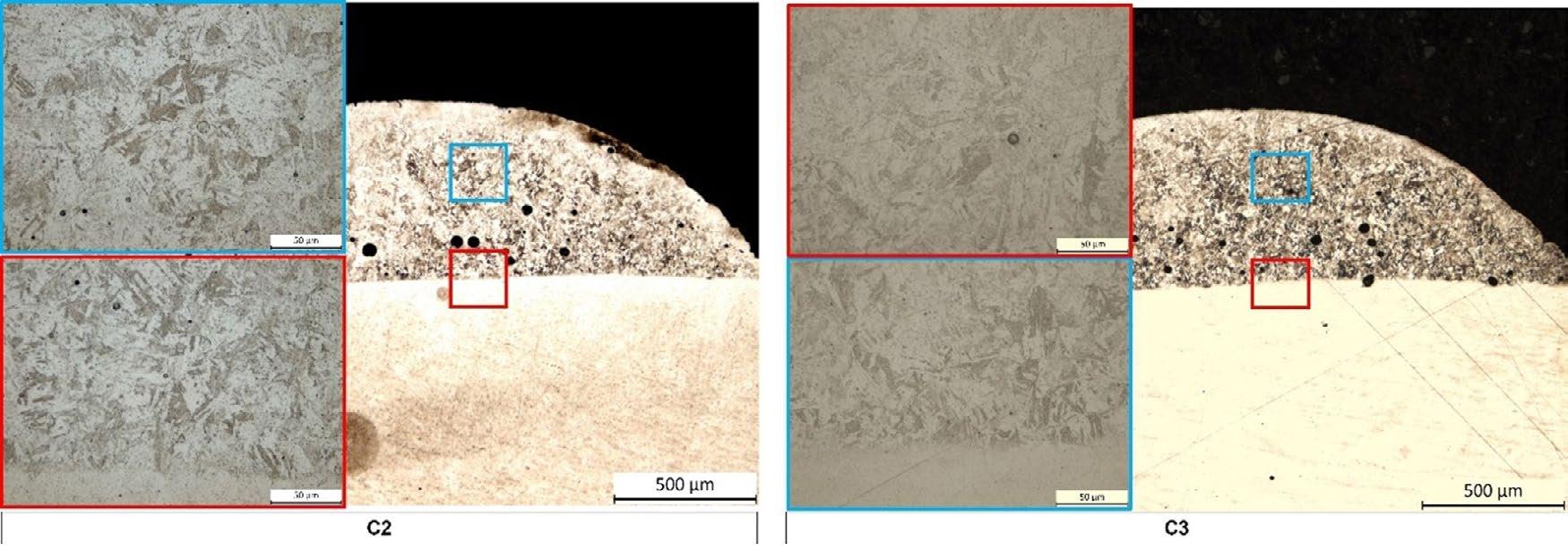
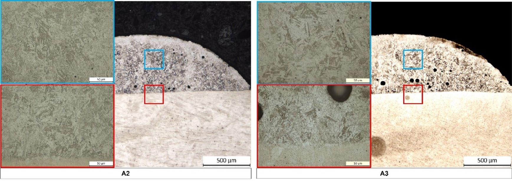
CONCLUSIONS
In the present work, the effect of different heat treatment routes on microstructure and hardness of 17-4 PH single tracks deposited by DED on an AISI 316L substrate were investigated. The following conclusions can be drawn:
• As-built samples drawn from the 17-4 PH tracks showed a typical martensitic matrix characterized by the presence of intergranular δ -ferrite in the deposited clad. The morphology of δ -ferrite is more lathy across the interface with the substrate. The amount of δ -ferrite decreases from the interface to the top of the track according to the thermal gradient induced by the process.
• The investigated heat treatment routes promoted the dissolution of the δ -ferrite during the austenitization step of the treatment, regardless of the aging time.
• The maximum increase in hardness was obtained with standard solubilization and already after 60 mins of aging (HT1_60). The shorter solubilization route (HT2) is effective in obtaining hardness values comparable with HT1_60 only extending the duration of aging up to 300 mins (HT2_300).
Further investigations need to be performed in order to confirm these preliminary results and other combinations of solubilization and aging times will be explored.
BIBLIOGRAFIA
[1] ASTM International, Standard Guide for Directed Energy Deposition of Metals. 2016, pp. 1–22.
[2] S. Sreekanth, “Laser-Directed Energy Deposition : Influence of Process Parameters and Heat-Treatments,” University West, 2020.
[3] R. M. Mahamood, Laser Metal Deposition of Metals and Alloys. 2018.
[4] S. Sreekanth, E. Ghassemali, K. Hurtig, and S. Joshi, “Effect of Direct Energy Deposition Process Parameters,” Metals, vol. 10, no. 1. p. 96, 2020.
[5] A. Steponaviciute, A. Selskiene, K. Stravinskas, S. Borodinas, and G. Mordas, “17-4 PH stainless-steel as a material for high resolution laser metal deposition,” Mater. Today Proc., vol. 52, pp. 2268–2272, 2021, doi: 10.1016/j.matpr.2021.08.143.
[6] A. A. Adeyemi, E. Akinlabi, R. M. Mahamood, K. O. Sanusi, S. Pityana, and M. Tlotleng, “Influence of laser power on microstructure of laser metal deposited 17-4 ph stainless steel,” IOP Conf. Ser. Mater. Sci. Eng., vol. 225, p. 012028, 2017, doi: 10.1088/1757899x/225/1/012028.
[7] J. Tacq., “L-PBF and Heat Treatment of 17-4PH steel,” 2021.
[8] A. Ziewiec, A. Zielińska-Lipiec, and E. Tasak, “Microstructure of welded joints of X5CrNiCuNb 16-4 (17-4 PH) martensitic stainlees steel after heat treatment,” Arch. Metall. Mater., vol. 59, no. 3, pp. 965–970, 2014, doi: 10.2478/amm-2014-0162.
[9] Y. Sun, R. J. Hebert, and M. Aindow, “Effect of heat treatments on microstructural evolution of additively manufactured and wrought 17-4PH stainless steel,” Mater. Des., vol. 156, pp. 429–440, 2018, doi: 10.1016/j.matdes.2018.07.015.
[10] K. Li et al., “Effect of homogenization on precipitation behavior and strengthening of 17-4 PH stainless steel fabricated using laser powder bed fusion,” Addit. Manuf., vol. 52, pp. 1–26, 2022, doi: 10.1016/j.addma.2022.102672.

[11] M. A. Bouaziz, J. M. Djouda, M. Chemkhi, M. Rambaudon, J. Kauffmann, and F. Hild, “Heat treatment effect on 17-4PH stainless steel manufactured by Atomic Diffusion Additive Manufacturing (ADAM),” Procedia CIRP, vol. 104, pp. 935–938, 2021, doi: 10.1016/j. procir.2021.11.157.
[12] S. D. Meredith, J. S. Zuback, J. S. Keist, and T. A. Palmer, “Impact of composition on the heat treatment response of additively manufactured 17–4 PH grade stainless steel,” Mater. Sci. Eng. A, vol. 738, no. September, pp. 44–56, 2018, doi: 10.1016/j. msea.2018.09.066.
[13] S. Sabooni et al., “Laser powder bed fusion of 17–4 PH stainless steel: A comparative study on the effect of heat treatment on the microstructure evolution and mechanical properties,” Addit. Manuf., vol. 46, no. June, p. 102176, 2021, doi: 10.1016/j. addma.2021.102176.
[14] H. R. Lashgari, C. Kong, E. Adabifiroozjaei, and S. Li, “Microstructure, post thermal treatment response, and tribological properties of 3D printed 17-4 PH stainless steel,” Wear, vol. 456–457, no. February, 2020, doi: 10.1016/j.wear.2020.203367.
[15] S. M. Yeon et al., “Normalizing Effect of Heat Treatment Processing on 17-4 PH Stainless Steel Manufactured by Powder Bed Fusion,” Metals (Basel)., vol. 12, no. 5, 2022, doi: 10.3390/met12050704.
[16] M. Bahrami Balajaddeh and H. Naffakh-Moosavy, “Pulsed Nd:YAG laser welding of 17-4 PH stainless steel: Microstructure, mechanical properties, and weldability investigation,” Opt. Laser Technol., vol. 119, no. June, 2019, doi: 10.1016/j.optlastec.2019.105651
[17] A. Ziewiec, A. Zielińska-Lipiec, J. Kowalska, and K. Ziewiec, “Microstructure Characterization of Welds in X5CrNiCuNb16-4 Steel in Overaged Condition,” Adv. Mater. Sci., vol. 19, no. 1, pp. 57–69, 2019, doi: doi:10.2478/adms-2019-0005.
Studio degli effetti del trattamento termico sulla evoluzione microstrutturale di singole tracce in 17-4
PH depositate mediante tecnologia DED
In molti ambiti industriali, la tecnologia di manifattura additiva Direct Energy Deposition (DED) si sta diffondendo in modo significativo sia per la produzione di componenti near-net-shape sia per effettuare ripazioni o indurimenti superficiali. In questo contesto, l’acciaio inossidabile 17-4 PH risulta un materiale molto interessante sia per l’ottima resistenza alla corrosione sia per le sue elevate proprietà meccaniche. Nella memoria sono presentati i risultati preliminari di uno studio condotto per valutare gli effetti di differenti modalità di trattamento termico sulle proprietà di singole tracce di acciaio 17-4 PH depositate mediante tecnologia DED su di un substrato in AISI 316L. Mediante tecniche microscopia ottica sono stati indagati gli effetti della solubilizzazione e di differenti tempi di invecchiamento sulla microstruttura, con particolare attenzione al contenuto di ferrite δ all’interno delle tracce. Inoltre, prove di microdurezza Vickers hanno consentito di studiare l’evoluzione della durezza attraverso l’interfaccaia substrato/traccia.
PAROLE CHIAVE: ACCIAIO 17-4 PH, DIRECT ENERGY DEPOSITION, TRATTAMENTO TERMICO, MICROSTRUTTURA, MICRODUREZZA
Influence of casting defects on damage evolution and potential failures in hot rolling simulation system
U. Hanoglu, B. ŠarlerIn this research, a previously developed rolling simulation code, based on a novel meshless collocation method, is upgraded from a deformation theory with ideal material properties to a new mechanical model that considers predefined defects even before the rolling process occurs. Considering homogeneous casted steel free of errors to enter a rolling mill will not produce any reliable predictions of possible failures. Depending on the rolling schedule, failure might occasionally happen during rolling as well, most likely due to high strain rates, shear stress, temperature gradient, friction, etc. However, most simulations that try to foresee those possible failures by only considering the rolling process parameters are incomplete. Even at the macro level, previous defects from the casting play a crucial role in failure that might occur or come very close to during rolling. The damage variable is initially defined as the density of micro-voids in the material. Instead of fracture mechanics, continuum damage mechanics is considered here to analyse the mechanical behaviour of the rolled steel in parallel with the damage evolution. As a result, a damage tensor is calculated during the hot rolling simulation based on the current deformation state. In each deformation step, the effective stress tensor is redefined with the inclusion of the damage tensor. For simplicity, a two-dimensional slice model is considered in the simulations. These slices are aligned parallel to each other and perpendicular to the rolling direction. Since the simulations are 2D, the damage tensor has no components towards the rolling direction. The main advantage of the upgraded simulation system is to have a more realistic material model that considers the initial defects of the steel and reveals the damage effects throughout the simulation. This gives a good virtual estimation of where and when to expect failure. The user determines a critical damage state, which could also be determined based on experiments. In this work, multiple rolling schedules obtained from the industrial partner are tested considering different levels of damaged input billet to be rolled. Overall, a computer program with a user-friendly interface has been created to visualise all those essential mechanical results and the damage field based on C# and .NET framework.
KEYWORDS: SIMULATION; ROLLING; STEEL; SLICE MODEL; MESHLESS; RADIAL BASIS FUNCTIONS; DAMAGE
INTRODUCTION
In this research, a rolling simulation system based on a novel meshless solution [1] is upgraded by considering a damage model. The current system can simulate the hot rolling of steel based on elastic or plastic material properties and gives out results in terms of temperature, displacement, strains and stress. The rolling mill is usually placed right after the reheating furnace, where the casted billets are heated to a certain temperature. When the billet is rolled, it is crucial to keep the amount of deformation in a certain range. In most simulations, the material is considered defect-free at the beginning, but in reality, it
Scientific papers - Mathematical Modelling and Simulation
already contains defects. All those unwanted contents/ errors may be assumed as damage. In each representative volume element, the amount of damage over the volume gives us the local damage value to be used in simulations.
The first idea of including damage variables in the equations of material deformation is given by Kachanov
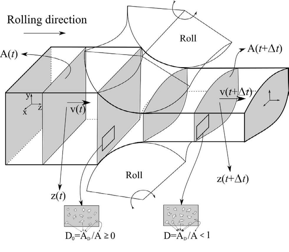
and Rabotnov [2-3]. They introduced a scalar damage variable. Later, Lemaitre [4] and Chaboche [5-6] used laws of thermodynamics to describe damage behaviour. Lemaitre [7], Chow and Wei [8] also came up with multiscalar models. However, a damage model with a scalar is considered in this paper.
In the simulations, a slice model assumption is used, as shown in Fig.1. This assumption lets us use 2D computational domains at each predefined position and the corresponding time. The slices are aligned towards the rolling direction. One slice at a time is subsequently simulated. Plane strain and planes remain planes assumptions are considered.
The hot rolling simulation system used here was
previously developed in [9], and uses a novel Local Radial Basis Function Collocation Method (LRBFCM) for the numerical solution. This method was first used to solve heat transfer problems [10] and afterwards applied to fluid flow [11] and solid mechanics [12].
SOLUTION PROCEDURE
From the deformation theory, the equilibrium equation has the following form
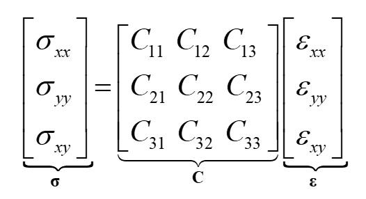
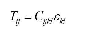

[1]
where T is the stress tensor, b is the body force vector. Stress tensor components Tij may be related to the strain tensor components klε with a 4th order stiffness tensor Cijkl ,
[2]
The Eq. 1 may be written in a vector form for over a 2D Cartesian coordinate system
If a scalar damage parameter D is introduced, the stress-strain relation becomes
The change of damage is related to
where Y is the dissipation power and is the free energy per unit volume, separated into elastic and plastic parts
For an undamaged state the free energy from the elastic part is calculated as . Based on the damage theory, the following relations may be obtained
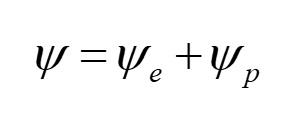

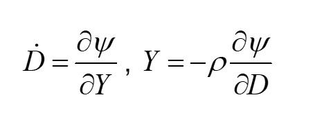
For the simulation of rolling, one of the following damage-included models may now be replaced with the non-damage model given in Eq. 3,
The relation for the damage evolution model is defined in [13] as
, AB are material constants, 0Y is the threshold for damage to start, and Y is the damaged value of Y .
NUMERICAL IMPLEMENTATION
The solution is obtained through local interpolation of the unknown displacement field. In the governing equation, the strain vector components may be written in terms of displacement vector components in 2D, as shown below:
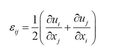


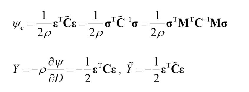
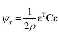
Instead of meshing, many collocation nodes are allocated over a computational domain which is a slice at a position under the roll. For each collocation node, displacement vector components and their derivatives are interpolated locally by considering only a certain number of nearest neighbouring nodes ( 7 N = ). ( ) ϕ p is the multi-quadrics radial basis function at the position ppxxyy=+ pii .

Interpolation of a displacement vector component and its derivative is shown below:
iγ are the collocation coefficients to be determined as a part of the solution procedure.

RESULTS
After the continuous casting of steel, the billet first goes into reversing rolling mill. Fig. 2-left below shows a
part of the billet's initial cross-section before rolling. In the pre-process of simulation, porosity over the slice is notated with a simple image processing algorithm Fig.2right. This data is transferred into colloca-tion nodes over the computational domain for the first slice before deformation takes place.
A numerical simulation is carried out with the initial damage data over a 180x180 mm slice with quarter symmetry considering only elastic deformation in 26 deformation steps with 900 uniformly distributed collocation nodes. The damage evolution results are shown in Fig.3 be-low,
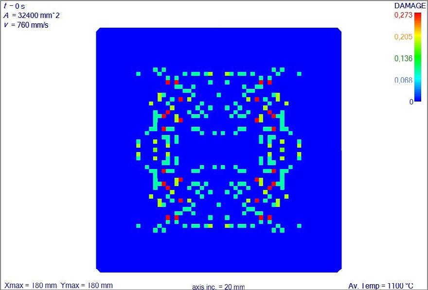
where the initial damage effect is still visible, and the highest damage is observed very locally at the corners. The parameters used in the damage evolution model, which should be experimentally defined, are 0.001 A = , 0.9 B = and 3 0 100 MJ/m Y = .
CONCLUSION
This work describes a rolling simulation system considering a damage model. In the simulations, a billet with porosity is considered, and initial values of the
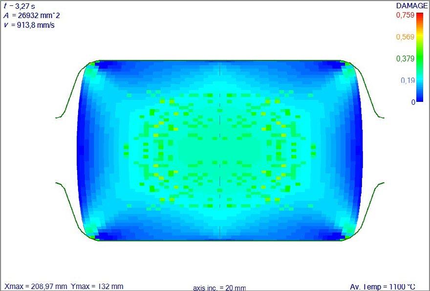
damage field are transferred into the simulation. After the first pass, damage results are shown. The inclusion of a damage model in a rolling simulation system has two major outcomes. First, damage sets limits to material
deformation based on the accumulated deformation history, which is much lower than the ideal material without damage. Second, the initial damage values are read and included in the damage evolution model to observe a more realistic damage evolution.
The damage value in damage evolution models tends to increase with deformation. However, in rolling, compressive stresses are dominant. Based on observations, most porosities might be eliminated
with proper rolling schedules. In the future, we need to experimentally investigate damage evolution in compression and develop a more appropriate damage model for rolling simulations.
ACKNOWLEDGEMENT
This research was funded by the Slovenian Grant Agency by grant numbers P2-0162 and L2-2609 and Štore-Steel Company (www.store-steel.si).
REFERENCES
[1] Hanoglu U, Šarler B. Multi-pass hot rolling simulation using a meshless method. Comput Struct. 2018;194:1-14.
[2] Kachanov LM. Time of the Rupture Process under Creep Conditions Otd Techn Nauk. 1958;8:26-31.
[3] Rabotnov YN. Creep Problems in Structural Members. Norton-Holland, Amsterdam, 1969.
[4] Lemaitre J, Evaluation of Dissipation and Damage in Metals Submitted to Dynamic Loading. Proc. I.C.M. I. 1971; Kyoto, Japan.
[5] Chaboche JL, Continuum damage mechanics: Part I—General concepts. J App Mech. 1988;55:59-64.
[6] Chaboche JL, Continuum Damage Mechanics: Part II—Damage growth, crack initialtion and crack growth. J App Mech. 1988;55:65-72.
[7] Lemaitre J, How to use damage mechanics. Nucl. Eng. Des. 1984;80:233-245.
[8] Chow CL, Wei Y. Constitutive Modeling of Material Damage for Fatigue Failure Prediction. Int. J. Damage Mech.1999;8:355-375.
[9] Hanoglu U, Šarler B. Hot rolling simulation system for steel based on advanced meshless solution. Metals. 2019;9:788-808.
[10] Šarler B, Vertnik R. Meshfree explicit local radial basis function collocation method for diffusion problems Comput. Math with Appl. 2006;51-8:1269-1282.
[11] Vertnik R, Mramor K, Šarler B. Solution of three-dimensional temperature and turbulent velocity field in continuously cast steel billets with electromagnetic stirring by a meshless method Eng. Anal. Bound. Elem. 2019;104:347-363.
[12] Mavrič B, Šarler B. Local radial basis function collocation method for linear thermoelasticity in two dimensions. Int. J. Numer. Method H. 2015;25-6:1488-1510.
[13] Saanouni K. Numerical Modelling in Damage Mechanics, Kogan Page Science, London, 2003.
Fast modelling of elastic work roll deformation in groove rolling
edited by: C. Renzing, M. Weiner, M. Stirl, M. Schmidtchen, U. PrahFor modelling of elastic work roll deformation in groove rolling, the finite element method offers a deep and detailed modeling approach. Nevertheless, FEM calculations require a great amount of computational power and time. For groove rolling, Schmidtchen et al. [1], [2] developed a pillar model derived from classic elementary theory to calculate the pressure distribution between groove contour and workpiece in width direction. A simplified model is available as a core model approach in the new simulation framework PyRolL developed at the institute of metal forming, Freiberg. In the current work, the framework is extended through a plugin focusing on the elastic deformation of the work roll. The implemented model calculates the elastic work roll deformation through bending and transverse contraction using matrix calculation and discretization of the work roll in width direction through disks. Besides, the grooved contour of the roll barrel also the roll journals are considered. This results in a bend line for the whole work roll which can further be used to adjust the rolling schedule or optimize the work rolls fatigue strength through more suitable material choice. To validate the model, the first calculations are made for simple groove shapes (Round, Oval, Diamond, Box) and results are first compared with FEM calculations witch shows good agreement.
KEYWORDS: ROLLING SIMULATION; GROOVE ROLLING; ROLL BENDING; SHAPE DEVIATION; ROLL PASS DESIGN
INTRODUCTION
In today’s world, high energy and material prices are increasing pressure on companies to reduce their scrap rates to keep manufacturing costs as low as possible. Main sources of scrap are process-related losses and rejects due to non-compliance with tolerances. Regarding the latter, one major requirement in the field of groove rolling is the shape deviation of the profiles compared to the specified shape. The shape of the profiles is influenced by the actual groove contour, the degree of filling, and the elastic response of the plant to loads and torques caused by the rolling process. Modeling the elastic deformation of the work rolls therefore gives crucial process insights needed to avoid the production of scrap by shape deviations. In the field of flat rolling there are various solutions to model the elastic behaviour of work rolls (f.e. [3, 4, 5, 6, 7, 8, 9]). As far as the authors are aware, only basic analytical calculations with major simplifications are published for groove rolling (f.e. [10, 11, 12]). Therefore, the matrix method by Göldner et al. [13] was adapted to provide a flexible and fast solution to model the elastic work roll deformation.
MODELLING OF ELASTIC WORK ROLL DEFORMATION
The core idea is to consider the roll as a prismatic rod with varying diameter and discretize its length into �� disks with length d��, which are subjected to a constant linear load �� and have a locally constant ��. Every disk has four state variables, which are the deflection ��, the inclination ��, the
bending moment ��B and the shear force ��Q. These four variables unambiguously determine the deformation and stress state of a disc. The values of the state variables at entry and exit of each disk are denoted by the indizes 0 and 1 (see Figure 1).
Fig.1 - a) Work roll for break down mill of the semi-continous roling plant at the institute of metal forming with exemplary load distribution and mechanical substitute system; b) disk element used for discretization.
Solving the 4th order differential equation for the deflection (see equation (1)) of a disk between its boundaries, under consideration of the above assumptions, allows the equations to be expressed as matrix. The resulting matrix is called transition matrix as it accomplishes the transition of the state variables in each disk. The entry state of the following disk can be calculated using the exit state of the previous disk through equation (2). As Becker et al. [12] and Kulbatschny [10] stated, the bearings of a roll are designed to be free of bending moments and have a very high bending rigidity. Göldner et al. [13] suggests, that bearings can therefore be modeled using spring constants resulting in a special transfer matrix for bearings. Since it was not possible to measure the necessary constants for

the respective plant, the spring constant and the torsion spring constant were assumed to be ∞ and 0, respectively. Furthermore, the bearing of the roll was approximated to be located at the center of each roll joints. In order to better represent the load on the roll resulting from the process, it was assumed that the pressure distribution in the contact area between the rolled material and the roll is elliptical and has its maximum in the centre of the groove. The width of the ellipse is equal to the width in which the rolled stock experiences hindered spreading. This width was calculated according to the model from Lendl [14]. A similar assumption was made by Hitchcock et al. [15] for elastic flattening of the roll, but in rolling direction. The assumptions can bee seen in Figure 1.
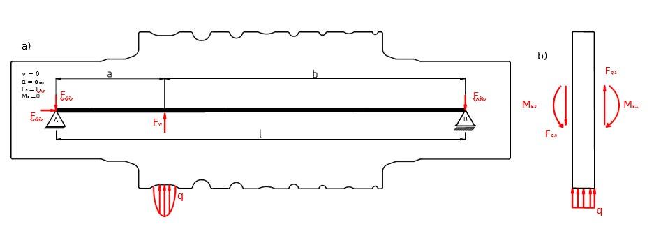
For performing the calculation, the components of the vector in point A must be known. Deflection ��(A) and moment ��B(A) are equal zero due to the assumptions.
The shear force ��Q(A) and inclination ��(A) are unequal zero and must be determined numerically, so that the deflection ��(B) and moment ��B(B) are zero in point B.


To estimate initial values for the numerical solution, a substitute system is used, namely the bending of a constant cross-section rod by a point force, as shown in
Using the initial solution, the final solution is computed using the HYBRD algorithm by Powell [16] provided in Scipy [17]. To test the model, the deformation of a work roll used for break down passes in a semi-continuous rolling plant located at the instiute of metal forming in Freiberg shall be investigated. The material rolled is a low carbon steel used for rebars with an initial round profile with a diameter of 8 mm rolled to a final diameter of 80 mm in fourteen passes. The results calculated are compared to results from the analytical model from Becker et al. [12].
ELASTIC DEFORMATION OF WORK ROLLS IN BREAK DOWN PASSES
The considered work roll is shown in Figure 2b and is equiped with a swedish oval groove as well as round and oval grooves. The model was tightly integrated into the open source framework PyRolL [18] as a plu- gin, to be able to investigate the influence of roll bending on the groove rolling process. The used PyRolL configuration, input scripts as well as the pass schedule are provided as supplementary material on GitHub (https://github. com/pyroll-project/pyroll-rolling-12-benchmark). The results for four selected passes (eg. first, third, fifth and tenth) from the calculation can be seen in Figure 2. These passes where chosen be- cause the grooves used for the respective pass are different from one another.
The results for the deflection, inclination, bending moment and shear force match the load distribution shown in Figure 2a. As one can see, the maximum values for load corresponds to the zero crossing of the bending moment and shear force.
The maximum value for the deflection is 0.017 mm and is located near the center of the work roll at z = 175 mm (see Figure 2b). Through the high stiffness of the work roll, resulting from the used material and diameter of the roll, the total deflection is vanishingly small. Comparison of the the bending moment and shear force results calculated using the described method to the results generated by the analytical model can be seen in Figure 2d. One can see that the average deviation lies within a few percent. The biggest difference between the two can be found in the shear stress which is caused by the different assumptions made for the pressure distribution. Becker et al. [12] applied the roll force as a point load at the center of the grooves contour. Therefore, the obtained results seem plausible and usage of the model is valid. For further usage of the model, it must be noted that the used groove contour as well as the shape of the initial profile have a considerable influence on the type of pressure distribution. The elliptical distribution used here represents a first approximation of the actual distribution, since the maximum rolling pressure is to be expected
near the centre of the groove due to the material flow, which is influenced by the grooves contour. Furthermore, it should be noted that the model can only be used up to a maximum filling ratio �� of 1.
SUMMARY AND OUTLOOK
The transition matrix approach offers a alternative to current simulations for simulation of the elastic work roll deformation for groove rolling. By using the matrix form
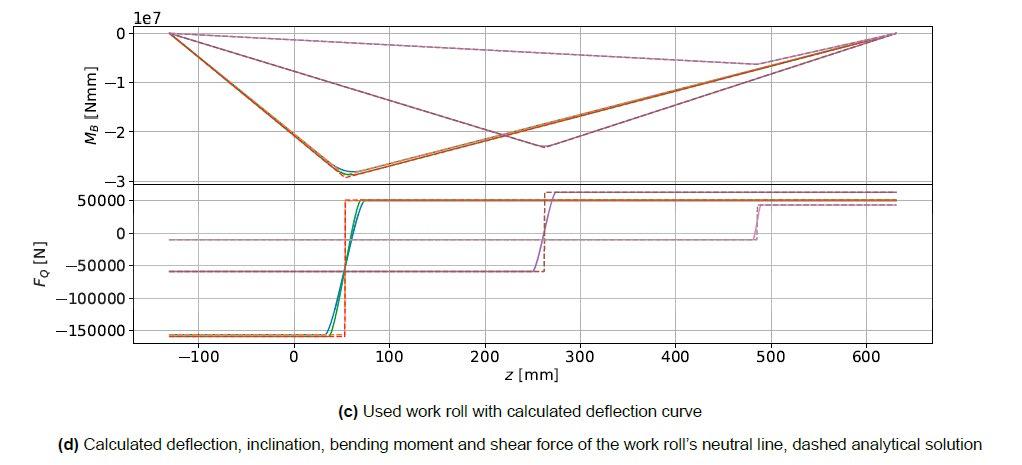
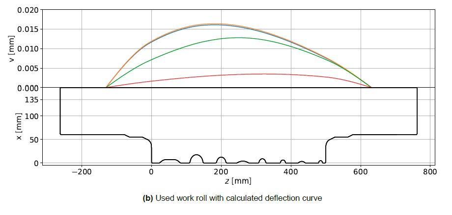
for the calculation of the deflection, the inclination, the bending moment and the shear force. To investigate the influence of the assumption for the load distribution, the model shall be combined with the pillar model developed by [1, 2] to calculate the elastic work roll deformation for the production of more complex irregular profiles. However, these studies will be the subject of a separate publication planned for the end of this year.
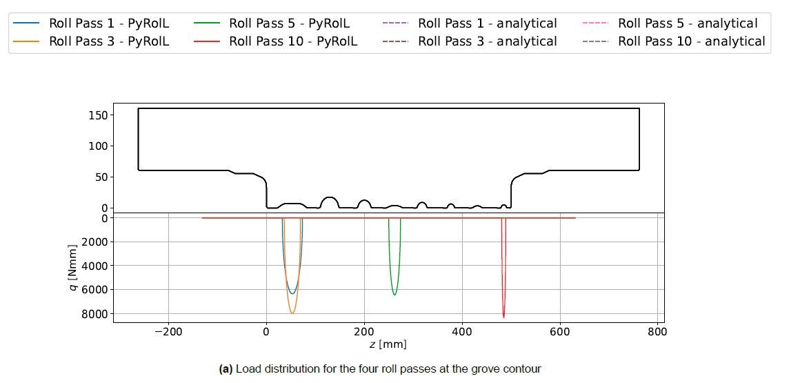
Scientific papers - Mathematical Modelling and Simulation
REFERENCES
[1] Matthias Schmidtchen, Frank Hoffmann, and Ulrich Prahl. “Development of Fast Simulation Tools with Higher Modelling Depth for Improved Description of Local Material Flow, Stress State and Microstructure in Breakdown and Shaping Grooves”. In: Der Kalibreur 80 (2020), pp. 27–40.
[2] M. Schmidtchen and U. Prahl. “Status of developments in (fast simulation assisted) groove pass design for asymmetric profiles”. In: Der Kalibreur 81 (2021), pp. 15–32. ıssn: 0022-796X.
[3] Oskar Pawelski and Fritz Lindemann. “Theoretische Betrachtungen zum Kaltwalzen von Breitband im Zusammenhang mit Betriebsmessungen an einem Vierwalzen-Umkehrgerüst”. de. In: Archiv für das Eisenhüttenwesen 35.7 (July 1964), pp. 619–632. ıssn: 00038962. doı: 10.1002/srin.196402362.
[4] Oskar Pawelski and Hermann Schroeder. “Einfluß der Walzenabplattung auf Walzspaltform und Druck- verteilung beim Kaltwalzen”. de. In: Archiv für das Eisenhüttenwesen 40.11 (Nov. 1969), pp. 867–873. ıssn: 00038962. doı: 10.1002/srin.196904399.
[5] B. Berger. “Die elastische Verformung der Walzen von Quarto-Walzgerüsten und die Beeinflussung der Walzspaltform durch Walzenbiegeeinrichtungen”. de. PhD Thesis. Freiberg: Technische Universität Bergakademie Freiberg, 1975.
[6] Gerd Beisemann. “Theoretische Untersuchung der mechanisch einstellbaren Bereiche für die Walzspalt- form an unterschiedlichen Walzwerksbauarten”. de. PhD Thesis. Aachen: RWTH Aachen, 1987.
[7] Jens Rieckmann. Berechnung von Bandprofil und Planheit beim Kaltwalzen auf Sechs-Walzen-Walzwerken. de. Umformtechnische Schriften. Düsseldorf: Stahleisen, 1989. ısbn: 978-3-514-00432-0.
[8] Hartmann. “Beitrag zur Modellierung der Planheit beim Warm- und Kaltbandwalzen”. de. PhD Thesis. Freiberg: Technische Universität Bergakademie Freiberg, 1990.
[9] A. Müller. “Beitrag zur Berechnung und Untersuchung der Walzspaltform und des Banddickenprofils an Quarto-Walzgerüsten”. de. PhD Thesis. Freiberg: TU Bergakademie Freiberg, 1992.
[10] I. G. Kulbatschny. Maschinelle Ausrüstung von Walzwerken. de. Berlin: VEB Verlag Technik Berlin, 1954.
[11] A. I. Zelikow. Lehrbuch des Walzwerksbaus. Berlin: VEB Verlag Technik Berlin, 1957.
[12] H. Becker, B. König, W. Guericke, and R. Hinkfoth. Walzwerke - Maschienen und Anlagen. Vol. 1. Leipzig: VEB Deutscher Verlag für Grundstoffindustrie, 1979.
[13] H. Göldner and F. Holzweißig. Leitfaden der technischen Mechanik. de. Vol. 11. Leipzig: VEB Fach- buchverlag Leipzig, 1989.
[14] A. E. Lendl. “Rolled Bars - Part I - Calculation of Spread between non parallel roll surfaces”. In: Iron and Steel 21.14 (1948), pp. 397–402.
[15] J. H. Hitchcock and W. Trinks. Roll neck bearings. en. New York, 1935, p. 51.
[16] M. J. D. Powell. “A Fortran subroutine for solving systems of non-linear algebraic equations”. en. In: (1968), p. 58.
[17] Pauli Virtanen et al. “SciPy 1.0: fundamental algorithms for scientific computing in Python”. en. In: Nature Methods 17.3 (Mar. 2020), pp. 261–272. ıssn: 1548-7091, 1548-7105. doı: 10.1038/s41592-019-0686-2.
[18] M. Weiner, C. Renzing, M. Stirl, M. Schmidtchen, and U. Prahl. “PyRolL - An Extensible OpenSource Framework for Rolling Simulation”. In: (2022). Manuscript submitted for publication.
TENSIL-PRO: from tensile properties calculation to incremental plasticity applications
A. Ferraiuolo, L. FerraiuoloTensil-Pro is a mathematical model able to evaluate in real time the tensile properties, in terms of yield stress, tensile strength, uniform elongation, elongation to rupture and additional important microstructural features such as grain size and recrystallized fraction. Tensil-Pro can be applied to all steels: single phase, multi-phase, ferritic and austenitic. In addition it can be applied also to other metallic alloys such as aluminium and copper. The basic approach starts from the Orowan equilibrium equation describing the rolling pressure distribution along the contact arc at the roll strip interface in the form of a differential equation and describing the rolling process in terms of the interaction of 3 main components: the work rolls, the lubricant and the workpiece. The material properties and the roll strip interaction are evaluated by means of a set of original constitutive equations whose parameters are determined with a self-training algorithm that need not laboratory tensile test results. Very recently was proposed a novel physical approach [5] to calculate the work hardening of metals undergoing a rolling deformation process (both hot and cold) on the basis of the rolling process parameters. The description of the evolution of microstructure in deformation process depending on the loading/straining history, as for example in hot rolling, requires the knowledge of the work hardening during each deformation step. The work hardening represents therefore the key enabler factor to build an incremental plasticity model able to describe, in real time, the evolution of microstructure, design the optimized rolling schedule and finally to realize a smart rolling process.
KEYWORDS: WORK HARDENING,
INTRODUCTION
Historically the main aim of the mathematical modelling of the rolling process, from the first model published more than 90 years ago, when von Kármán initiated the slab method [1], was, above all, the calculation of the rolling forces for the dimensioning of the stands, secondarily for the motors torque and power design. The mathematical model proposed in the present paper, Tensil-Pro, reversed the aim of the classic rolling modelling: the rolling force distribution, entry/exit tension and strip geometry in roll bite are input data of the model while the output values are the flow stress and work hardening of the workpiece. The friction force is introduced as a roll-strip boundary conditions with a friction coefficient assumed constant on the contact arc. The flow stress is evaluated on the basis of the stress
balance on the differential slab considering the friction hill in the roll bite. The theoretical background of the TensilPro to evaluate the work hardening is strictly related to the properties of the stress tensor. In plane strain conditions, the normal stress distributions can be calculated, without any knowledge of the deformations occurring in roll bite [2], from the general equilibrium conditions of the forces acting in roll bite (both vertical and longitudinal direction) together with the Huber–Mises plasticity condition. This favorable circumstance was exploited to define, as described in the next section, an analytical relationship between flow stress, work hardening and strip geometry in roll bite.
TENSIL-PRO MODEL: MATHEMATICAL APPROACH
Work hardening distribution in roll bite
where R’ is the deformed roll radius, S is the radial specific roll separating force, μ is the Coulomb friction coefficient and ϑ is the angular coordinate in the roll bite. The minus sign refers to entry side and the plus sign refers to the exit side with respect to the neutral plane. The vertical compressive stress q is related to radial force S by the following equilibrium equation
The above equilibrium equations contains 3 unknown functions, i.e. the horizontal pressure f for unit width, the radial pressure S and vertical pressure q. To find a unique solution the classic approach introduces a second relationship between the horizontal and vertical compressive stresses given by the Huber-Mises plasticity condition
In the above equation σ represents the compression yielding of the material and h is the local thickness of the slab. The mechanical equilibrium along the RD can be written, after some algebra reported in [6], in terms of normal pressure S, flow stress, work hardening and strip geometry in roll bite as follows:
Changing the derivative from angular variable ϑ to true strain, multiplying by and considering that the local strip thickness can be expressed as h=h o+2R'(1-cosϑ), after few algebra steps the equation (4) can be written as:


The tensil-pro approach for work hardening calculation is based on a relationship found, for plane strain conditions, between work hardening, flow stress and strip deformation geometry in roll bite. This represent a quite new approach that does not make use of the microscopic level of deformation but only concepts of the continuum mechanics and the classic Orowan rolling theory [2]. This methodology and its application in rolling process was recently filed for a patent application [7]. The theoretical approach start from the force equilibrium condition in longitudinal direction on a slab element (Figure 1):
The above equation (5), assuming S represented by Bland Ford function represents a relationship between work hardening a flow stress within the roll bite. This approach represents, at the knowledge of the authors, a new and quite interesting way to achieve important results in terms of calculation of work hardening in roll bite and application of an incremental plasticity model in rolling process. With this assumption the derivative it is calculated accordingly: [1]
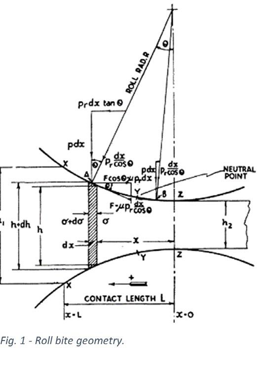
Substituting the equation (6) within the (5) it is found after some algebra the following equation:


In which Ω , named stability function, in case of slipping friction condition is defined as:
It is noteworthy to underline that the equation (7) is derived with the slipping roll-strip boundary conditions. The same approach can be applied also for sticking boundary conditions leading to a different expression for Ω function [5]. The equation (7), in addition to state that in rolling process the flow stress and work hardening are related each other, has many important implications on deformation stability in rolling process (stable if Ω ≥1). The detailed analytical derivation of this relationship and the discussion of its implications on the stability of rolling deformation as a function of strip deformation geometry and rolling process parameters (friction coefficient, roll radius, entry-exit tension) are discussed in a quite recent paper [5]. The integration, on the contact arc, of the equation (7) leads to the following results:
geometry in roll bite.
YIELD STRESS ONLINE EVALUATION
Where σ o is the yield at entry roll bite. The equation (10) can be integrated easily with Matlab toolbox. It highligths that the work hardening depend, through the function Ω , not only on total strain but also on the strip boundary conditions (friction, entry/exit tension) and the strip
The flow stress of the strip is evaluated starting from equation (3) through several mathematical steps. At the first step is calculated the roll pressure as a function of angular variable assuming a slipping friction boundary conditions (lubricated roll conditions). The work hardening of the strip is added in a later stage. The second step consists in the evaluation of the average roll pressure on the roll bite. The third step consists in reversing this equation: the flow stress of material as a function of the applied roll force, strip deformation geometry and other process parameters is obtained. The calculated flow stress is related to friction coefficient and for this reason this aspect requires a special attention. The friction coefficient is continuously calculated adopting a standard approach but a specific model parameter is associated in order to control and monitor eventual deviations of the cold rolling process. The adopted approach allows the Tensil-Pro to be quite reliable and very sensitive to strip metallurgical characteristics: grain size, second phases, precipitation pattern and so on. This guarantees an high sensitivity to HDG process conditions (speed line, soaking temperature) if Tensil-Pro is installed in skin pass, and an high sensitivity to hot rolling process conditions if the Tensil-Pro is installed in the first stand of cold rolling mill. At this stage the calculated flow stress is dynamic in the sense that is referred to the actual strain rate adopted in the process. So the value must be scaled up to the quasistatic conditions (about 10-4s-1) adopting the well-known constitutive approach. The tensile strength and then uniform elongation and total elongation are evaluated thanks to original constitutive equations and specialized to each steel grade by means of model parameters.
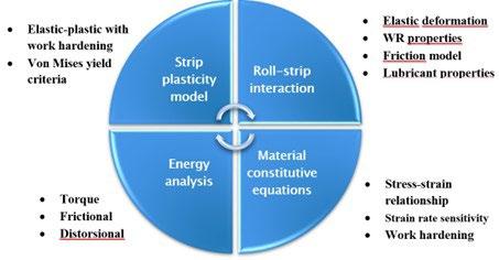
TENSIL-PRO RESULTS: ONLINE EVALUATION OF TENSILE PROPERTIES
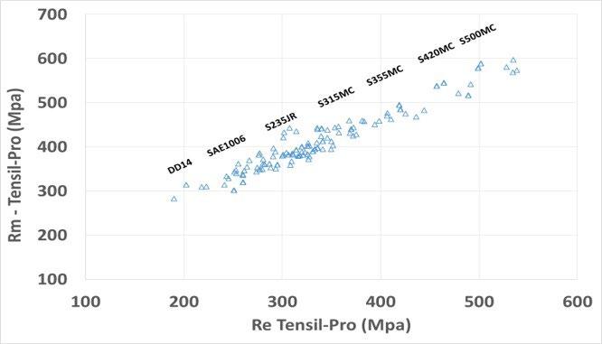
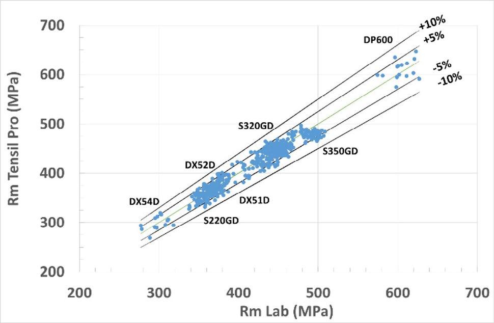
HDG steel products
The evaluation of tensile properties on the whole length of the galvanised coils is carried out adopting the Tensil-Pro model installed on the PLC of the skin pass. At Ravenna
plant Tensil-Pro is installed on all the 4 hot dip galvanising lines. In the figure 3 is reported the results of Tensil-Pro in terms of tensile strength (Rm) obtained on galvanising line n.4 compared with tensile test results for different steel grades. As it can be noted for all the steel qualities the agreement is significantly better than ±10%.
Hot rolled carbon steel
The evaluation of tensile properties on the whole length of the hot rolled coils is carried out adopting the TensilPro model in the first stand of the cold rolling mill. At Ravenna plant, Tensil-Pro is installed in 2 reversible mills (double stands) and 1 Tandem mill (5 stands). In figure 4 are reported the average tensile properties, in
terms of yield stress and strength, of the whole product mix of the tandem mill. It is interesting to note that the hot rolled coils were produced by several steel works with significant process differences. The plot of figure 4 is very helpful to evaluate the statistical homogeneity and for benchmarking of the tensile properties of hot bands produced by different steelworks.
Stainless steel grades
Tensil-Pro represents, at moment, the only industrial system able to evaluate online the tensile properties of both austenitic and ferritic stainless steels. In the figure 5 are reported the industrial results of Tensil-Pro obtained on AISI304 stainless steel grade compared with laboratory
tensile test results obtained on the annealing and pickling line n.2 of Marcegaglia Gazoldo plant. In this case the Tensil-Pro model is installed in the PLC of the skin pass of the line. As it can be noted the agreement is within the ±10% for both yield stress (Re) and much better for tensile strength (Rm).
INCREMENTAL PLASTICITY APPROACH
The mathematical description of a specific deformation process with multi axial stress state can be approached in two different ways: the first is the ‘total deformation approach’ and, the second is the ‘incremental plasticity theory’. The first approach is simpler and should be applied when a relationship between total strain with total stress exist, i.e. no stress history effect can be accounted for. A good field of application of this approach is represented by simple cold deformation processes in which the deformation is consisting of a single o very few deformation step. The incremental plasticity is basically a differential approach in which strain increments are related to stress increment so that the history effect can be accounted for. There is no doubt that the incremental theory of plasticity is more general and more applicable
than the total deformation approach but the issue is typically related to higher mathematical and conceptual complexity. It is quite evident that the incremental plasticity is the only theoretical approach usable in high temperature deformation process where, the occurring of softening process together with multi axial stress state, does not allow the application of a simple total deformation approach. Therefore the incremental plasticity theory is based on the need to define an equation that correlates the strain increment to stress increment, i.e. the work hardening. The equation (7) represents the fundamental building block for an incremental plasticity approach to evaluate the microstructure evolution in rolling process. In fact in a multi stage deformation process, the flow stress of the workpiece at the exit of the n-th step is the product of n work hardening terms:
In which σ o is the entry flow stress at the first rolling stand and Ω _i are the stability functions of each deformation step (figure 6). The value of work hardening is depending on both stress, stress history and the relevant plot along the roll bite could be not continuous. In fact if we proceed along the roll bite and calculate it by breaking the loading path into segments of different stress mode (plastic loading under tension, compression, unloading under compression and finally tension), in each segment, we
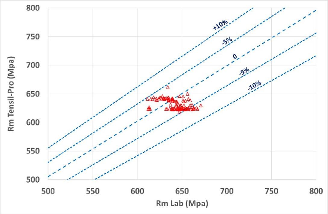
can determine according with equations (9,10,11). In the case of a hot rolling application aiming to follow the microstructure evolution in multi passes rolling process the calculation of total work hardening requires the integration of the terms ∫ Ω n d ε on the whole roll bite. The proposed approach is shortly resumed in the following sections.

INCREMENTAL PLASTICITY APPLICATION IN HOT ROLLING PROCESS
Detection of softening and hardening
The plastic deformation of austenite is carried out at high temperatures and strain rate and competition between hardening (dislocation storage) and softening (dislocation density reduction) mechanisms occurs. Furthermore the softening mechanisms, recrystallization and recovery, are manifold (static, dynamic, metadynamic) and characterised by quite different kinetics. With the
In which σ eq (T, ε i ,ε̇) represents the equivalent stress calculated at the i-th rolling pass, σ y (T,ε i ,ε̇) is the yield stress of the material under processing at the strain rate ε and temperature T evaluated according [6]. The total work hardening ∆ σ WH (T,εi, ε ) represents the cumulative


Where the first term is the residual work hardening (due to previous passes), and the second, , is the instantaneous work hardening of the i-th pass calculated with the equation (10). With this method it is possible to detect, for each rolling pass, the occurrence of softening mechanisms due to dynamic/metadynamic/static recrystallization or hardening (retained strain).
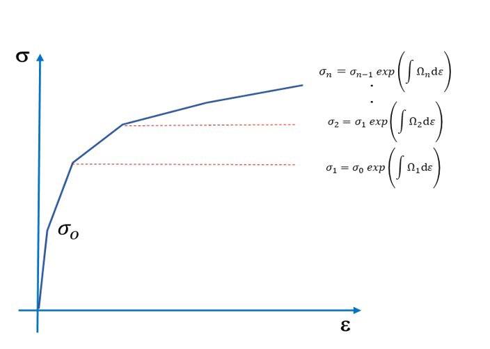
Hot rolling tests results
The proposed incremental plasticity approach was ap-
knowledge of the instantaneous work hardening the stress-strain path occurring during the hot rolling process can be reconstructed, premised that the flow stress of workpiece as a function of deformation temperature and the equivalent stress in each rolling pass are calculated [7]. The calculation of the work hardening in real time allows the possibility to adopt an incremental approach and to reconstruct the strain path along the rolling schedule. The basic incremental equation for i-th rolling pass is: [12] [13]
hardening occurring in the strip/plate, after ‘i’ rolling passes. The total work hardening ∆ σ WH (T,εi, ε ) represents the cumulative hardening mechanisms occurring in the strip/plate, after ‘i’ rolling passes, i.e.:
plied to investigate the evolution of the retained strain and recovery/recrystallization in a plate hot rolling mill (Marcegaglia Plates plant). In table 1 is reported the chemical composition of the microalloyed steel grades selected for the investigation. The hot rolling schedule is characterised by an initial slab thickness of 250mm and a final plate thickness of 70mm. The initial/final temperature are respectively 1030°C / 870°C.
In the figure 7 is reported the calculated yield stress as a function of temperature according with [6] for the selected microalloyed steel. In the figure 8 is shown the cumulated strain applied (sum of the strain pass), the retained strain along the hot rolling process (strain path) calculated following the approach described above. In the same plot is reported also the critical strain for dynamic recrystallization ε c [6]. This plot represent just an example of the application of the proposed approach. As a general trend, microalloyed steel can recrystallize only above the no-recrystallization temperature (Tno_rex). At temperature below Tno_rex recrystallization could occur only if enough long time is waited. Each point in the plot correspond to a single rolling pass with the
characteristic temperature and strain rate. The effect of strain rate is quite evident especially for the last passes in which typically the strain rate reaches 3-4 s-1. In the hot rolling schedule reported in figure 8 the temperature in the initial passes is slightly lower and different interpass time were adopted. These differences in the hot rolling process produced a significantly different retained strain path. In the first 9 passes no accumulation of strain is detected. The result would suggest that recovery is occurring, so during the interpass time the recovery process determined a rearrangement of dislocations leading to a decrease of flow stress. At lower temperature the retained strain increases and no softening seems to occur.
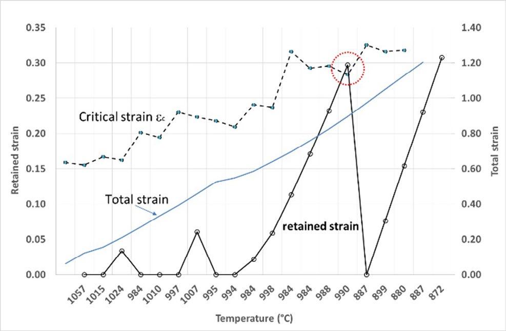
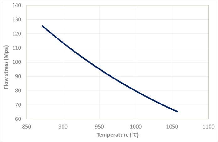
The rolling pass in which occurs a drop of retained strain (marked with red circle) is corresponding to a long interpass time (300s) and in this case static recrystallization occurred. This analysis represents an interesting investigation opportunity, i.e. it could make possible to obtain the evolution of the recrystallization/recovery mechanisms and to design the hot rolling schedule (TMCP) with significantly low energy consumption on the basis of reliable industrial results.
CONCLUSIONS
In the present paper it was presented a new methodology for online monitoring of the tensile properties, work hardening, strain path, and microstructure evolution during strip/plate rolling (hot and cold). This approach is applicable to all steels (austenitic, ferritic) and also other alloy systems (Aluminium first of all). The main theoretical results proposed in the paper is that under axially symmetric conditions (plane strain) in rolling process
exists a relationship between the work hardening, flow stress and strip boundary conditions in the roll bite (friction, entry/exit tension). The knowledge of work hardening allows to built up an incremental plasticity model approach thanks to which is possible to reconstruct the stress-strain path history quite directly. The evaluation of both work hardening and flow stress as a function of temperature and strain rate, make it possible to discriminate the softening/hardening contribution of each rolling pass and finally to determine the retained strain at each rolling pass. As a corollary it is possible to gather further metallurgical informations to study the role played by alloying elements and other fine metallurgical factors,
such as the stacking fault energy (SFE), on controlling recrystallization and work hardening. This methodology applied to hot rolling process appears quite promising to realize a Smart Rolling process in which the smart sensors can be used to evaluate online adjustments to the hot rolling schedule. A further development of this approach could be addressed to the optimization of the energy consumptions related to hot rolling process (slab reheating temperature, steel chemical composition) and to study the strain-rate sensitivity and strip temperature profile on the recrystallization phenomena.
REFERENCES
[1] T. Von Karman, Zeitschrift fur Angewandte, Mathematik und Mechanik 5, 1925, 139-141.
[2] Orowan E. 1943, Proc., Inst. Mech. Eng. 150,140.
[3] D. R. Bland, H. Ford, “The calculation of roll force and torque in cold strip rolling with tensions”, Proceedings of the Institute of Mechanical Engineers, London 159, 1948, 144-163
[4] W. L. Roberts, “Cold Rolling of Steel”, Marcel Dekker, Inc., 1978
[5] L. Ferraiuolo, A. Ferraiuolo; Novel approach for work hardening and plastic stability evaluation in flat rolling process. Part I: slipping friction condition; Material Science and Engineering, to be published.
[6] A. Ferraiuolo, Investigation on softening/hardening mechanisms occurring during the hot rolling process by means of advanced, self-training virtual smart sensors, AISTech 2021 Iron & Steel Technology Conference Proceedings Volume I, ISBN: 978-1-93511793-3
[7] Ferraiuolo A., Patent PCT/EP2022/059077, april 2022.
TORNA ALL'INDICE
Optimized & adaptable cooling path control through a novel runout table controller at hsm2 of Tata Steel in ijmuiden
edited by: R.C.J. Speets, R.W.G. Keijsers, K.C.J. Schutte, R.A. van Dok, J.S. Mosk, R.D.M. Mestrom, M. BsibsiAfter coils have been rolled in a hot strip mill, the strip enters the run-out table where the strip cools down from approximately 900°C to 600°C depending on the requirements. The run-out table of the HSM2 at Tata Steel in IJmuiden is about 130 meters long and has 124 sections (62 above and 62 below the strip) that can be independently actuated: off, half flow rate and full flow rate.
At IJmuiden a new controller is developed to fulfil the increasing demands for new steel grades. The main goal is to have full flexibility on the cooling strategy and control. To achieve this, a setup optimizer has been developed that computes the optimal cooling path based on a set of objectives and constraints. From a control perspective, the runout table is divided into multiple control zones and the strategy determines how each of these zones is controlled. The aim is to have the same temperature-time profile for each point in the strip, considering speed changes and varying finishing temperatures.
The controller is implemented in 2021 at IJmuiden Hot Strip Mill 2 and meanwhile is used for all products. To smoothen the implementation and to avoid homologation of all products at once, the former setup is completely integrated and translated to the new controller philosophy. The controller runs now for more than 12 months, and the major benefit is the ability to develop and produce new steel types. An additional advantage is a significant improvement in temperature performance that results in substantial reduction of repairs and rejects.
KEYWORDS: HOT STRIP MILL, RUNOUT TABLE, COOLING, CONTROL
INTRODUCTION
At the IJmuiden Hot Strip Mill (HSM), coils are heated to a temperature between 1150 and 1250°C and then hot rolled in a five-stand rougher section and a sevenstand finishing section. After finishing the strip enters the runout table at a temperature between 900°C and 1050°C. The runout table of the HSM is about 130 meters long and has 124 sections: 62 sections above the strip and 62 below the strip, that can be independently actuated: off, half flow rate and full flow rate. Good control of the runout table is vital to realise desired product qualities. Conventional control of the HSM runout table is based on a setup that selects a pattern from a fixed set (see Figure 1) and on feedforward controller based on the finishing temperature combined with a feedback controller for
finetuning. Optionally a fixed intermediate feedforward control point can be selected for spe-cial grades. This conventional controller was developed around the year 2000 and was already a step forward in runout table
control [1,2] employing a simplified first-principle strip temperature and heat transfer model. Later this model was extended with an advanced transformation model, called MITRON [3,4] for improved prediction of
of HSLA and dual phase material. During the years this heat transfer model was extended with additional pattern types to allow for the ever-growing demands for advanced steel types. Around 2015 it became clear that extending pattern types is not a sustainable solution in the rapid changing environment of new product development and tighter associated requirements. This resulted in the development of the next generation runout table setup and control.
The main goal of the new controller is to realize the transition from a target intermediate and coiling
temperature control to a flexible temperature-time path control. In Fig. 2 some possible temperature paths on the ROT are shown resulting in different micro-structures at the end of the ROT. The possible temperature paths and resulting product micro-structures are found within the working envelope (green) of the installation. This working envelope is a result of the combination of alloy content and applied process. The available window of cooling paths is determined by the hardware and the strip speed on the Run Out Table.


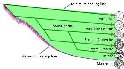
MODEL AND ADAPTATION
The first principle model consists of three parts:
• Strip temperature model
• Material model for predicting transformation
• Heat transfer model
with boundary conditions:


T0 Finishing mill entry temperature [K]
qtr Transformation heat during cooling [J/kg]
q0 Boundary condition at top and bottom surface
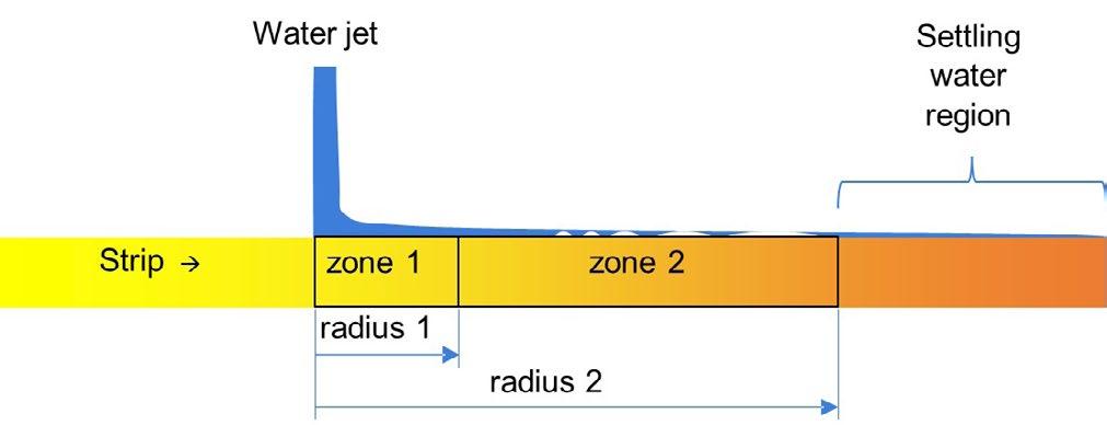
Transformation model
An accurate prediction of the transformation and latent heat of transformation are important in the calculation of the temperature evolution. Therefore, the transformation model that was already developed for the previous ROT controller, is also incorporated in the new version. This model is called MITRON and is developed in-house. It is a fully physics-based phase transformation model and runs successfully for many years in the Tata Steel hot strip mills in Europe [3,4]. Due to the availability of four EMSpec
Strip temperature model
The temperature in the strip is computed using a onedimensional non-equidistant grid using the gradient heat conduction equation [5]:
devices [6] (which measure the ferrite fractions in the steel) the MITRON model is further improved and tuned.
Heat transfer model
The heat transfer in the Runout table is dominated by the water cooling. To compute the water cooling at the strip surface, the heat transfer coefficient is computed based on the so-called boiling curves at different cooling zones after impact of the water, see Fig. 3.
The heat transfer coefficients are based on the boiling curves shown in Fig
Inaccuracies
Although the model is based on first principles, the predicted temperature still deviates from the measured temperatures. For this, various reasons exist, such as runout table mechanical status, such as valve deterioration, Strip surface properties, model inaccuracies and measurement inaccuracies.
To counteract these inaccuracies, two solutions are implemented:
• Model correction by using an artificial neural network (ANN)
• Model adaptation by linear regression
Model correction using an artificial neural network
The model error is calculated using an offline version of
the thermal model in combination with historic data. The error between the calculated and measured temperatures is minimized by applying a wise correction on the heat transfer coefficient.
This correction is then correlated to various input parameters using the ANN:
• Water temperature
• Most relevant alloying elements
• Finishing temperature and coiling temperature
• Average speed
• Strip thickness and width
The training of the ANN resulted in a correlation with a R² of 0.65, as shown in Fig. 5.
The application of the ANN improved the average model accuracy by around 19%.
Adaptation
The model correction by the ANN already increases the model accuracy significantly, but cannot correct for time variant behaviour (e.g., status of the runout table over time) and rapid coil-to-coil variation. For this, two different adaptation methods are included, both based on linear regression:
• Long term adaptation based on heat transfer correction
• Short term adaptation based on a temperature correction
OPTIMIZER
The new runout table controller consists of mainly two stages, namely setup and controller. This subdivision is also found in the conventional controller [1,2], however the implementation is different. The setup uses an optimizer to find the best cooling pattern for the coil, based on:
• Selected strategy
• Strip dimensions and PDI (targets)
• State of the runout table (such as available sections and adaptation)
Strategy
A strategy is a description for the setup optimiser on what
to optimize. This strategy consists of three parts: Objective functions, constraints, and control parameters. The objective functions are stored as a list with desired targets over the length of the runout table. The ‘target’ can be defined as strip temperature, but also different targets are possible, such as surface temperature, austenite fraction, heat flow density.
Constraints are defined as domains and a domain is a (configurable) part of the runout-table which the optimizer can utilise to fulfil the objectives. In the domain the maximum and minimum section load can be enforced and
subjected to
Where x is the set of the cooling section loads (valve positions) to be found. Since there are 124 cooling sections and each cooling section has two flow levels this results in a problem with 124 unknowns and 3124 possible solutions.
This vast search space results in two problems:
• Computationally intensive due to the problem size
• The system is heavily underdetermined.
Because the system is underdetermined, there is a risk of obtaining different cooling patters for virtually identical strips and this is highly undesired. Furthermore a ‘smooth’ pattern is preferred, meaning that a pattern should be repetitive and continuous to ensure constant cooling rate. Because of this desired property the individual section load is replaced with cooling zone length and cooling intensity. This results in three unknowns for a simplest cooling strategy:
• Cooling zone length (number of sections)
• Cooling intensity on top and bottom (0% – 100%)
also the degree of symmetry can be imposed. Furthermore, the domains can have a ‘fixed’ start and end position on the runout-table, but domains can also be interconnected, so the second domain starts directly after the first domain. This allows for high flexibility.
The control parameters are also part of the strategy but are not relevant in the setup phase and therefore this part is described in the section about the controller.
Problem description
In fact, the optimization problem can be described as:


For more complex cooling strategies, the number of unknowns expands accordingly. The algorithm allows for both connected zones (next zone directly starts after) or distinct zones (next zone starts on a fixed bank position). Since the sections have only three positions (off, half open, fully open), the cooling intensity is ‘digitized’. This computes a pattern that matches the intensity as close as possible.
Genetic algorithm
This problem is non-linear mixed integer problem and there are different optimization techniques available to handle this type of optimization. Due to the nature of the optimization problem, gradient based optimization methods are not suitable. Therefore, the most promising methods are simulated annealing or genetic algorithm [7]. Although the simulated annealing algorithm is faster, the genetic algorithm gives better results. Hence, the genetic algorithm is applied.
The layout of the gene follows from the choice of the cooling zone length and intensities:
Objectives
The use of an unstructured optimization function has the advantage to use various, nonlinear objectives, such as:
• Strip temperature at a given position
• Cooling rate target and limits
• Phase transformation targets,
• Heat flow density target or distribution
• Surface temperature limitation
The resulting objective function for coiling temperature is then:

For other objective functions, a similar objective function is applied. The different objectives combined as a weighted sum:

Constraints
A genetic algorithm as no constraints other than the limitations in the gene build-up. However, ‘soft’ constraints are part of the objective function using a high weight. Hard constraints are either resolved by gene repair, as explained before, or by rejecting the outcome.
CONTROLLER
After the setup has completed, the setup results need to be employed and this is part of the controller. The controller consists of two parts: feedforward and feedback.
Feedforwards
The feedforward (FF) iteratively computes the required zone lengths for each domain using the thermal model. The computation uses the measured entry temperature, target domain temperature, expected time-speed schedule and the domain definitions in the setup. This is then translated to a valve send-out.
Feedback
The feedback (FB) computes the error between the measured pyrometer temperature and the expected temperature from the thermal model. This temperature error is fed back and considered in the next feedforward. This
results in a modified Smith predictor scheme [8]. The number of active controllers depends on the control zone definition in the strategy and are related to the domain setup. This means that a control zone consists of one or more domains.
Implementation at IJmuiden HSM2
The new controller is implemented at HMS2 in the period of 2020 to 2021 and runs since February 2021. To have a smooth transition from the previous controller the legacy setup is integrated completely in the new controller as alternative setup. This legacy setup has been used for the majority of the coils, until a correct strategy was defined.
RESULTS
The controller runs now for more than 12 months, and the major benefit is the ability to develop and produce new steel types. An additional advantage is a significant improvement in temperature performance that results in substantial reduction of repairs and rejects.
New product development
The new setup is already used for many new steel types.
• Controlled cooling of very high alloyed steel:
• In this development the phase transformation
is difficult to control and just imposing a coiling temperature is insufficient to obtain the right phase transformation. To successfully control this grade, an intermediate point is applied with two distinct cooling rates. This strategy improves the controllability of the process for this material significantly, resulting in less material rejections.
• Surface temperature limitation:
• In this development the surface temperature limitation is imposed to improve strip shape issues. This strategy improves the controllability of the process
for this material significantly, resulting in less material rejections.
Performance improvement
The new implementation also has a benefit on overall performance: The number of rejects were reduced significantly after implementation and the cost of poor quality (COPQ) is now structurally at very low level. and Fig. 6 and Fig. 7 show the temperature performance comparison before and after implementation.
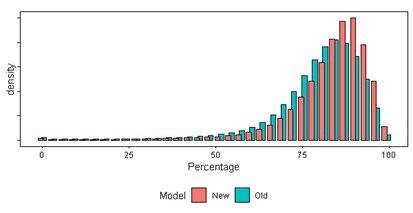
Scientific papers - Mathematical Modelling and Simulation
REFERENCES
[1] Luinenburg AW, Onink M, Ritman VA, New physical on-line model for coiling temperature control in Hot Strip Mill #2, 7th International Conference on steel rolling, Makuhari, Chiba, Japan, Nov. 9-11, 1998.
[2] Luinenburg AW, van Leeuwen Y, Mosk JS, Successful implementation of a physical on-line model for coiling temperature control in CORUS’ Hot Strip Mill #2 at IJmuiden, 8th International Conference on steel rolling, Orlando, USA September 2002.
[3] Luinenburg AW, Brown KJ, Snijders HM, Physical on-line model for coiling temperature control in CORUS’ hot strip mill of IJmuiden and Port Talbot, METEC 2003 Düsseldorf, June 16-20, 2003.
[4] Bsibsi M et al., Implementation of a physically based phase transformation model for the coiling temperature control in Tata Steel Europe Hot Strip Mills, European Rolling Conference 2013.
[5] VDI, VDI-Wärmeatlas 5th edition, 1988, ISBN 3-18-400850-9,
[6] Yang H et al, EM sensor array system and performance evaluation for in-line measurement of phase transformation in steel, Insight vol 61-3, March 2019.
[7] Weise T, Global Optimization Algorithms, Theory and Application, 26-080-2009, www.it-weise.de.
[8] Smith OJ, Closer control of loops with dead time, Chemical Engineering Progress, 53 (1957), pp. 217–219
[9] Roffel B, Betlem B, Process dynamics and control: modeling for control and prediction; 2006, UK, Wiley.
co-organised by

17TH INTERNATIONAL CONFERENCE ON SEMI SOLID PROCESSING OF ALLOYS AND COMPOSITES

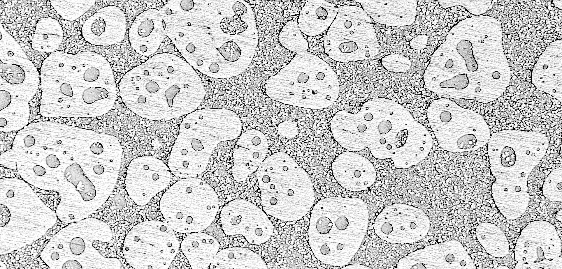
BRESCIA · ITALY, 6-8 SEPTEMBER 2023
On behalf of the Organizing Committee, we are pleased to invite you to the 17th International Conference on Semi Solid Processing of Alloys and Composites (S2P2023), which will be held from September 6th to 8th, 2023 in Brescia, Italy. The 17th S2P International Conference focuses on the advancement in fundamental knowledge and development of materials and industrial processes for semi-solid manufacturing of high-performance metal components. This conference will continue a successful series of conferences on semi-solid processing of alloys and composites started in 1990. We are looking forward to welcoming you in Italy!


TOPICS
The Conference is devoted to all aspects of semi-solid processing of metals alloys and composites with emphasis on basic research, engineering application as well as market aspects. Results of engineering research and experience as well as scientific issues are relevant for the conference.

ORGANISING SECRETARIAT
AIM – Associazione Italiana di Metallurgia
Via Filippo Turati 8 – 20121 Milano – Italy
Tel. +39 0276021132 or 0276397770
met@aimnet.it – www.aimnet.it/s2p/
SUPPORTER & MEDIA PARTNERS
Effetto di polveri di FeSi3 sulla formazione di idrati di metano e anidride carbonica
A. M. Gambelli, G. Stornelli, F. Rossi, A. Di SchinoQuesto articolo descrive la formazione di gas idrati, con metano e anidride carbonica come composti ospiti, in un apparato sperimentale su piccola scala, appositamente progettato per riprodurre i giacimenti marini offshore. Il sedimento era costituito da sabbia porosa di quarzo puro impregnata di particelle di FeSi3, prodotte tramite gas-atomizzazione e solitamente destinate ad applicazioni nella manifattura additiva. I risultati sperimentali sono stati confrontati con le condizioni teoriche di equilibrio per entrambi i tipi di idrati. Il principale obiettivo di questa ricerca consiste nell’individuare e testare additivi solidi nel processo di formazione e dissociazione degli idrati di metano ed anidride carbonica, con lo scopo di individuare potenziali promotori del processo di scambio, tra le due specie, nei giacimenti naturali di gas idrati.
INTRODUZIONE
I gas idrati sono composti cristallini simili al ghiaccio, che si formano spontaneamente in natura in presenza di adeguate condizioni termodinamiche e, chiaramente, in presenza di molecole d'acqua. Queste ultime, si legano tra loro formando legami idrogeno e realizzando delle strutture cristalline solide attorno alle molecole gassose. Le molecole gassose costituiscono le principali responsabili del processo e sono fisicamente (non chimicamente) contenute in queste gabbie [1, 2]. Comunemente, le molecole d'acqua sono indicate come "hosts", mentre il composto gassoso è chiamato "guest" [3]. Diverse sostanze sono in grado di ricoprire il ruolo di “guest”; le più significative sono metano, anidride carbonica, azoto, propano, etano, butano, acido solfidrico, xeno, argon e altre [3]. In particolare, in natura sono stati scoperti degli enormi giacimenti di idrati di metano e le attuali stime confermano che il metano in essi contenuto è sufficiente a produrre almeno il doppio dell'energia ancora ottenibile con tutte le fonti energetiche convenzionali conosciute dall'uomo. Inoltre, il metano (CH4) può essere recuperato iniettando
Alberto Maria Gambelli, Federico Rossi, Andrea Di Schino
Università degli studi di Perugia, Italiaalbertomaria.gambelli@unipg.itfederico.rossi@unipg.it - andrea.dischino@unipg.it
Giulia Stornelli
Università degli studi di Roma – Tor Vergata, Italiagiulia.stornelli@students.uniroma2.eu
molecole di anidride carbonica (CO2) nel giacimento e favorendo uno scambio naturale, tra questi due composti, in gabbie d'acqua già esistenti [4]. Questo dipende dalle diverse proprietà dei due gas [5, 6]. Di solito, entrambi formano strutture idrate di forma cubica, definite con la sigla sI (abbreviazione di Structure I). Tale struttura è composta da due differenti tipologie di cavità poliedriche, una relativamente piccola, costituita da un dodecaedro pentagonale e una relativamente grande, costituita da un tetracaidecaedro. Le molecole di metano prediligono le gabbie grandi ma possono adattarsi ed entrare in quelle piccole. Al contrario, le molecole di anidride carbonica possono occupare solo le grandi gabbie. Inoltre, l'entalpia di formazione è diversa per i due gas e risulta inferiore per l'anidride carbonica, che richiede – 57,98 kJ/mol, invece di – 54,49 kJ/mol, necessari per la formazione di idrati di metano.
Queste differenze consentono di recuperare metano e, allo stesso tempo, di immagazzinare una pari quantità di anidride carbonica in forma solida, realizzando così un processo completamente carbon neutral. Tuttavia, prima di essere competitivo e attraente per le industrie coinvolte in questo campo, il processo deve essere migliorato e devono essere risolte diverse sfide critiche. Ad esempio, la bassa cinetica o le difficoltà legate alla scarsa diffusione delle molecole di CO2 nel giacimento, causata della sua bassa permeabilità, unitamente alle difficoltà legate al raggiungimento degli ambienti in cui questi depositi sono solitamente localizzati, rendono attualmente il processo di sostituzione complesso ed eccessivamente energivoro. Diverse tecniche sono comunemente adottate nei processi sostitutivi; le più diffuse sono la depressurizzazione [7], la stimolazione termica [8] e l'uso di additivi chimici [9]. Le prime due strategie sfruttano la tendenza degli idrati di CO2 a formarsi in condizioni termodinamiche più miti rispetto agli idrati di metano: pressione e temperatura vengono così modificate per generare instabilità per gli idrati di metano e favorire la sostituzione tra le due differenti molecole nelle gabbie d'acqua preesistenti. Gli additivi chimici sono generalmente adottati per creare la stessa instabilità, ma senza alterare le condizioni termodinamiche locali. Sebbene l'efficacia di quest'ultimo metodo sia promettente, viene raramente applicato poiché la maturità tecnologica del processo non è stata ancora raggiunta
[10-13]. Questo articolo fa parte di una ricerca più ampia, che è focalizzata nella definizione di nuovi potenziali additivi, utili a migliorare l'efficienza della sostituzione e, allo stesso tempo, aventi un impatto trascurabile sull'ambiente [14, 15]. In particolare si è tenuto conto degli additivi solidi, al fine di rendere trascurabile la diffusione delle sostanze nell'acqua. In questo lavoro si sono formati idrati di metano e anidride carbonica in presenza di una sabbia porosa di quarzo puro, utilizzata per simulare un giacimento di idrati off-shore e con l'aggiunta di una polvere di FeSi3, prodotta tramite atomizzazione a gas e solitamente destinata ad applicazioni nella manifattura additiva [16-18] in particolare nel campo dei materiali per l’energia [19]. Questa polvere è stata scelta perché il Fe è un noto inibitore della formazione di idrati di gas, mentre il Si è generalmente neutro.
Gli esperimenti sono stati condotti in un reattore di piccola scala ed i risultati sono stati poi confrontati con le condizioni di equilibrio per entrambi i composti, stabilite con una raccolta di quanto presente in letteratura.
MATERIALI E METODI
L'apparato sperimentale è costituito da un reattore di piccola scala, di forma cilindrica e volume interno pari a 949 cm3. Le due estremità sono chiuse con due flange, i cui piatti sono mantenuti a contatto tramite otto elementi filettati (per ciascuna di esse). Tra i due piatti di ciascuna flangia è stata inserita una guarnizione spirometallica, in modo da garantire la tenuta del reattore ed evitare perdite di gas. Il reattore è immerso in un bagno termostatico, direttamente collegato ad un chiller (modello GC-LT) per regolare la temperatura interna. Il chiller è collegato ad una doppia serpentina in rame, posizionata sul lato interno della parete laterale del bagno. Il fluido refrigerante sottrae calore all’acqua contenuta nel bagno; questa a sua volta, sottrae calore al reattore. Uno schema dell'apparato sperimentale è mostrato in Fig. 1.
La temperatura è controllata attraverso quattro termocoppie di tipo K (classe di accuratezza 1), posizionate a diverse profondità (rispettivamente a 2, 7, 11 e 16 cm di profondità dall'alto) e necessarie per rilevare possibili gradienti interni durante la formazione degli idrati. La pressione viene misurata con un manometro digitale (modello MAN-SD), avente classe di accuratezza pari a ± 0.5% del fondo scala. Infine, tutti i dispositivi sono collegati a un sistema di acquisizione dati prodotto da National Instruments e gestito in LabView. Informazioni più dettagliate sull'apparato sperimentale possono essere trovate altrove in letteratura [20, 21].
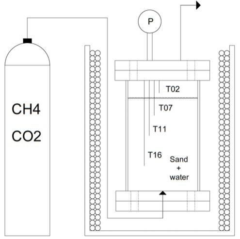
Sono stati utilizzati metano e anidride carbonica puri, con grado di purezza superiore al 99.99%. Il reattore è stato riempito con 236 cm3 di acqua pura demineralizzata e 744 cm3 di sabbia. Quest'ultimo elemento è realizzato con quarzo puro con granulometria sferica di diametro approssimativamente pari a 90 – 150 µm. La porosità del sedimento è stata misurata con un porosimetro (modello Thermo Scientific Pascal) ed è pari al 34%. Il mezzo poroso è stato impregnato con particelle di FeSi3. Per prima cosa è stato inserito il sedimento (sabbia porosa e additivo solido)
e, a seguire, l’acqua. Il reattore è stato quindi sigillato. Il gas è stato inserito tramite un canale di immissione collegato alla flangia inferiore e schematizzato in Figura 1. Il gas è stato inserito fino al raggiungimento della pressione interna desiderata. Considerata la tipologia di sperimentazione, non si è resa necessaria alcuna ulteriore misurazione della portata o della quantità di gas immessa.
La polvere metallica FeSi3 è stata prodotta mediante processo di gas-atomizzazione e la sua caratterizzazione morfologica è stata effettuata mediante microscopio elettronico a scansione ad alta risoluzione (FE-SEM Zeiss LEO-1530) (Fig. 2). La composizione chimica della polvere è Si= 3.00 wt%, C= 0.01 wt%, O=0.0001 wt% e Fe a bilanciare.
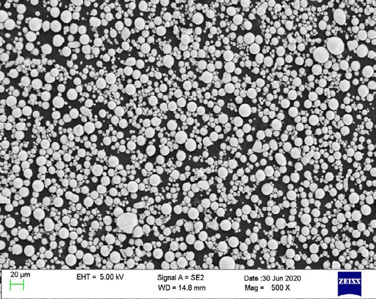
In Fig. 3 è riportata la distribuzione della dimensione delle particelle (PDS, Particle Size Distributions) misurata con il metodo di diffrazione laser (MAsterizer 3000, MalvernPanalytical) con la dimensione delle particelle, espresse in percentuali volumetriche al 10 vol%, 50 vol%, 90 vol%, uguali a: D10= 14.4 µm, D50= 30.8 µm e D90= 56.4 µm. In generale la polvere presenta una morfologia sferica con qualche satellite (Fig. 2) e con valori di ellitticità prossimi a 1.

Gli idrati di metano e anidride carbonica si sono formati in presenza di pura sabbia di quarzo impregnata con 200 g di particelle di FeSi3, corrispondenti al 17.36% in peso del
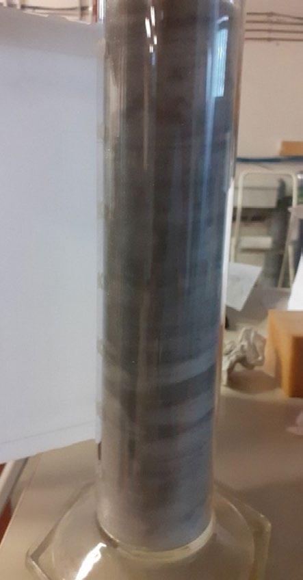
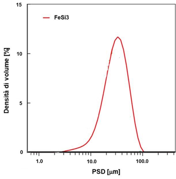
La formazione e la dissociazione degli idrati sono state effettuate secondo ricerche precedenti [22, 23]. Dopo una prima fase di pulizia, effettuata facendo scorrere il composto ospite attraverso il reattore a pressione leggermente superiore a quella atmosferica, il reattore è stato riempito di gas fino a raggiungere la pressione desiderata ed infine è stato chiuso. Le opportune condizioni termodinamiche che hanno portato alla formazione di idrati, sono state rilevate principalmente osservando l'andamento della pressione nel tempo. Non appena la pressione ha smesso di diminuire e si è stabilizzata, il processo di formazione è stato considerato terminato. Subito dopo, il chiller è stato
spento e la temperatura ha iniziato ad aumentare all'interno del reattore. In questo modo la temperatura aumentava lentamente e gradualmente e permetteva di definire la curva di dissociazione con elevata precisione. Le curve così prodotte sono state infine confrontate con le condizioni di equilibrio degli idrati di metano e anidride carbonica, diagrammati sulla base dei dati raccolti dalla letteratura [2426].
RISULTATI E DISCUSSIONE
Durante la sperimentazione condotta in questo lavoro, sono stati formati idrati di metano e anidride carbonica in
presenza di un mezzo poroso di quarzo puro impregnato di particelle di FeSi3. Durante ogni prova, pressione e temperatura sono state misurate e quindi correlate per produrre le curve di formazione e dissociazione. Quest'ultima rappresenta le condizioni di equilibrio per gli idrati ed è stata confrontata con la configurazione di equilibrio teorica, definita con i dati raccolti dalla letteratura. Tale confronto ha consentito anche di verificare se il particolare additivo utilizzato in questo lavoro ha agito come promotore, inibitore o non ha mostrato nessuno di questi effetti. Inoltre, le molecole di gas sono intrappolate fisicamente e non chimicamente all’interno delle strutture cristalline degli idrati quindi, la formazione di questi ultimi non altera la composizione chimica dei composti.
La Tab. 1 mostra le condizioni di pressione e temperatura misurate durante la dissociazione degli idrati in entrambi gli esperimenti, mentre la Fig. 5 e la Fig. 6 descrivono l'intero esperimento (sia la formazione che la dissociazione). Infine, al fine di garantire la riproducibilità della procedura e, di conseguenza, la veridicità dei risultati, ogni esperimento mostrato nel testo è stato ripetuto più volte, con le stesse condizioni iniziali ed osservando la medesima procedura; tuttavia, per ragioni di brevità, nel testo ogni diversa configurazione è stata descritta con un unico esperimento. In merito alla procedura adottata, ulteriori dettagli e conferme sulla validità della stessa, possono essere trovate in letteratura [27, 28].
Tab.1 - Condizioni termodinamiche sperimentali misurate durante la dissociazione degli idrati e confrontate con i valori teorici di equilibrio / Experimental thermodynamic conditions measured during hydrates dissociation and compared with theoretical equilibrium values for both guests.
L'andamento osservato in entrambi i diagrammi conferma quanto presente in letteratura [1]: formazione e dissociazione sono diverse tra loro e questo dipende da diversi fattori. In primo luogo, gli esperimenti sono spesso condotti in apparati di piccola scala (inferiore a un litro) e, anche i più grandi reattori utilizzati [29], sono ovviamente in serbatoi più piccoli di quelli reali e le condizioni al contorno non sono trascurabili. Le pareti perimetrali dei reattori forniscono solitamente siti favorevoli alla
nucleazione degli idrati e intervengono fortemente sul trasferimento di calore complessivo. La sfida più toccante è associata alla produzione di calore durante la formazione dei primi nuclei. La formazione degli idrati è un processo esotermico e il calore rilasciato può modificare le condizioni termodinamiche locali, avvicinando il sistema alla curva di equilibrio, ovvero al confine della zona di formazione. A causa del ridotto volume del reattore, il rilascio di calore potrebbe temporaneamente muovere
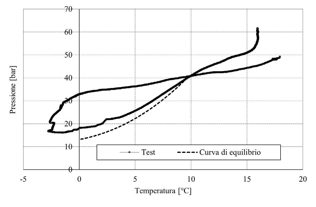
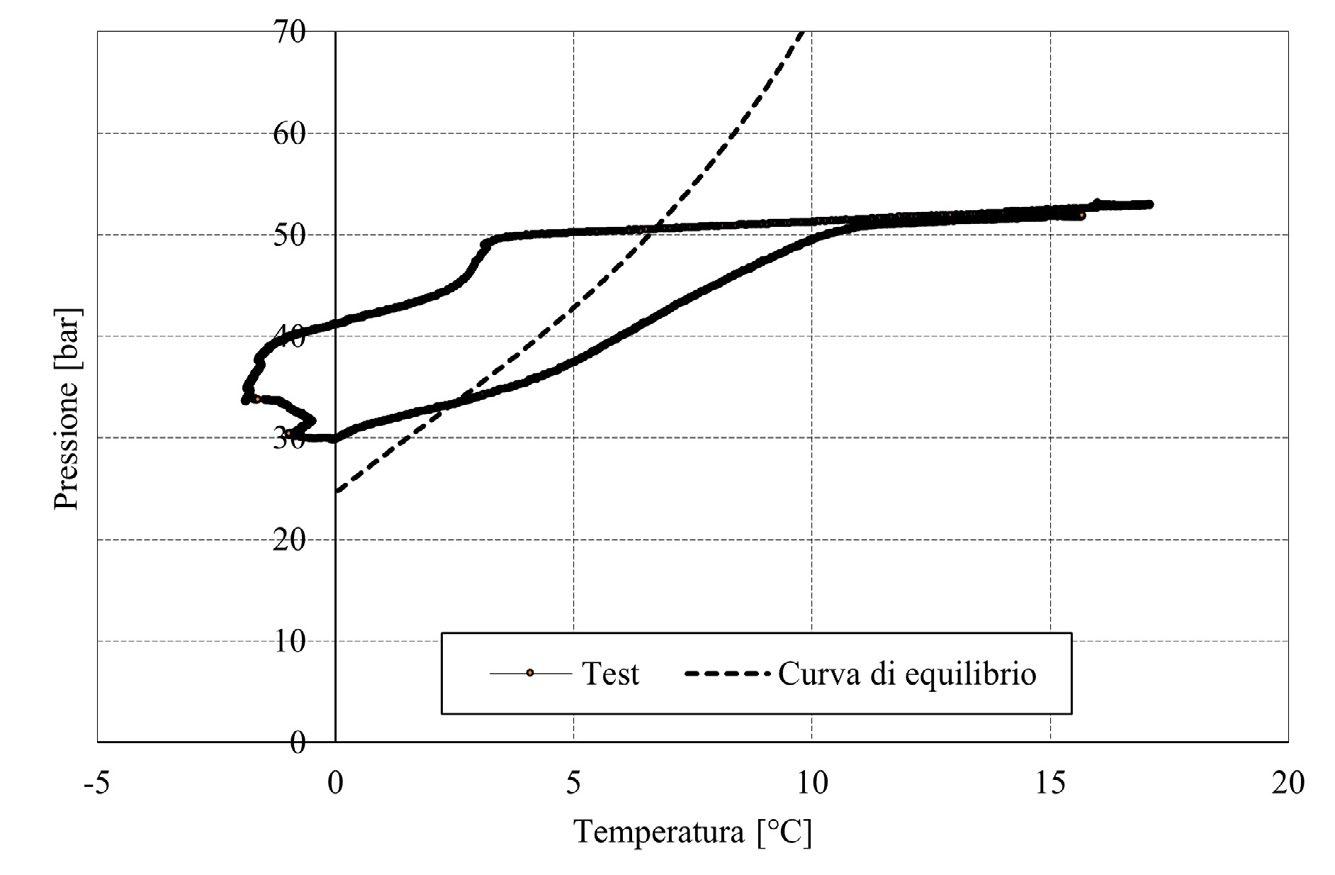
le condizioni interne oltre tale limite, andando ad inibire temporaneamente il processo di formazione (vedi Fig. 5 e 6). Un altro problema cruciale risiede nella permeabilità del mezzo poroso. La formazione di conglomerati idrati può ostacolare la diffusione di molecole gassose nell'intero reattore. Di conseguenza, in alcune porzioni di reattori, il processo potrebbe iniziare con un certo ritardo e modificare la curva generale. Al contrario, la dissociazione degli idrati è più lineare e spesso riflette il processo ideale, perché non è influenzata dalla maggior parte di queste sfide. Tuttavia, tale differenza non può essere giustificata solo in questo modo e devono essere compiuti ulteriori sforzi per caratterizzarla bene.
Sulla base dei valori riportati in Tab. 1 e degli andamenti descritti nelle Fig. 5 e 6 , le particelle di FeSi3 hanno svolto il ruolo di promotori degli idrati di metano. Con la loro presenza, la curva di dissociazione è sempre rimasta al di sotto del limite di equilibrio, denotando che erano necessarie condizioni termodinamiche più miti per garantire la stabilità degli idrati presenti all'interno del reattore. La curva sperimentale e quella di equilibrio non sono parallele, dimostrando che il processo è avvenuto in modo diverso da quello teorico. Tuttavia, l'effetto promotore è chiaro e ben visibile in quasi tutto il processo. Ad alte temperature la differenza era significativa, ad esempio a 9 °C gli idrati di metano si sono dissociati a 47.4 bar invece che a 66.2 bar, differentemente a 5 °C i rispettivi valori erano 37.4 bar e 43.7 bar. A temperature più basse, la differenza tra questi due valori e, infine, la situazione opposta si è verificata a temperature inferiori a circa 2 °C. La formazione di idrati di metano è terminata in condizioni termodinamiche ampiamente al di sopra del confine di equilibrio; di conseguenza, da quelle condizioni è partita la prima parte della fase di dissociazione. Per tale motivo, in questa fase iniziale, è leggermente al di sopra dell'equilibrio. Ulteriori precisazioni sono necessarie sul lato opposto, dove la presenza di polvere sembrava ridurre la pressione di dissociazione di oltre 20 bar. Tale differenza si è verificata quando quasi tutti gli idrati si erano già dissociati e la relazione tra pressione e temperatura era cambiata. Durante questa fase, tale relazione ha seguito principalmente l'equazione di stato per i composti gassosi e si è verificata solo una piccola dipendenza dal processo di dissociazione degli idrati.
Al contrario, le particelle di FeSi3 sembravano inibire il processo in presenza di anidride carbonica come guest. In questo caso, la curva sperimentale è rimasta sempre al di sopra delle condizioni di equilibrio per gli idrati di CO2. Le due tendenze sono abbastanza parallele ed è stato osservato solo un debole effetto inibitorio. Ad esempio, a temperatura pari a 3 °C, la pressione richiesta per la dissociazione era di 22.2 bar anziché 17.5 bar; a temperatura pari a 8 °C i corrispondenti valori di pressione erano 34.4 e 33.4 bar. Inoltre, sia la curva di formazione che quella di dissociazione suggerivano che a temperature superiori a 10°C l'additivo avrebbe agito da promotore del processo. Quest'ultima fase risente però della stessa criticità rivelata nel test precedente (la pressione si stava ormai avvicinando al valore massimo) e di conseguenza quest'ultima ipotesi non può essere fatta.
Nonostante l'effetto dovuto alla presenza di particelle di FeSi3, va tenuta in considerazione anche l'azione promotrice esercitata sul processo dal mezzo poroso di quarzo puro. Tale mezzo è stato caratterizzato in precedenti ricerche [30] e, anche secondo quanto presente in letteratura [29-32], ne è emersa la sua funzione da promotore, grazie all'aggiunta di siti idonei alla nucleazione degli idrati ed alla presenza di pori che generano piccole interfacce gas-liquido nell'intero volume del reattore.
Considerando quest'ultimo contributo, si può concludere che l'additivo FeSi3 ha avuto un effetto promotore neutro o debole sugli idrati di metano, mentre ha inibito significativamente gli idrati di anidride carbonica.
Tuttavia, la preparazione della miscela sabbia-particelle all'interno del reattore, ha permesso di trarre alcune conclusioni significative. Con alta probabilità, queste particelle hanno promosso il processo da un punto di vista fisico. La Fig. 7 mostra questa miscela prima degli esperimenti e immediatamente prima della formazione degli idrati.
La presenza di particelle di FeSi3 ha portato alla formazione di bolle gassose circondate sia dai granelli di sabbia che dalle particelle di FeSi3. Considerando l'umidità contenuta nei pori della sabbia, tale configurazione ha migliorato enormemente l'interfaccia gas-liquido e, in questo senso, ha favorito il processo.
L'analisi dei sedimenti dopo la formazione degli idrati ha rivelato che bolle simili si sono verificate nell'intero
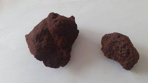
before hydrates formation.
reattore e non solo nella parte superiore.
In presenza di acqua, la miscela ha prodotto un sedimento cementato che ha ostacolato la diffusione delle molecole di gas nell'intero reattore. Figura 8 mostra dei campioni di sedimento estratti dal reattore al termine della sperimentazione. Si può vedere chiaramente il fenomeno di compattazione e cementificazione precedentemente menzionato.
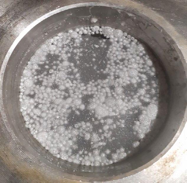
CONCLUSIONI
Questo articolo tratta della formazione e dissociazione di idrati di metano e anidride carbonica in un apparato sperimentale su piccola scala e in presenza di sabbia porosa composta da quarzo puro, impregnata con poveri di FeSi3. Gli esperimenti condotti e mostrati in questo lavoro hanno messo in evidenza il debole effetto promotore che le polveri di FeSi3 hanno per gli idrati di metano ed il buon effetto inibitore che invece assumono per gli idrati di anidride carbonica. Il loro effetto inibente risulta legato alle proprietà chimiche. Quest'ultima conclusione
concorda con i dati presenti in letteratura che descrivono molecole e ioni Fe come un inibitore del processo. Infine, l'analisi dei sedimenti ha svelato perché la formazione degli idrati risulti estremamente diversa dalla successiva dissociazione: la cementazione dei sedimenti ostacola la diffusione dei gas e solo alcune porzioni del reattore risultano coinvolte nella formazione degli idrati, probabilmente con un certo ritardo tra loro.
[1.] Koh CA, Sloan ED. Natural gas hydrates: recent advances and challenges in energy and environmental applications. AIChE Journal, 53 (2007) 1636 – 1643.
[2.] Gambelli AM. Analyses on CH4 and CO2 hydrate formation to define the optimal pressure for CO2 injection to maximize the replacement efficiency into natural gas hydrate in presence of a silica-based natural porous medium, via depressurization techniques. Chemical Engineering and Processing – Process Intensification, 167 (2021) 108512.
[3.] Rossi F, Gambelli AM. Thermodynamic phase equilibrium of single-guest hydrate formation data of hydrate in presence of chemical additives: a review. Fluid Phase Equilibria, 536 (2021) 112958.
[4.] Gambelli AM, Filipponi M, Rossi F. How methane release may affect carbon dioxide storage during replacement processes in natural gas hydrate reservoirs. Journal of Petroleum Science and Engineering, 205 (2021) 108895.
[5.] Lee YJ, Kawamura T, Yamamoto Y, Yoon JH. Phase Equilibrium Studies of Tetrahydrofuran (THF) + CH4, THF + CO2, CH4 + CO2, and THF + CO2 + CH4 Hydrates. Journal of Chemical & Engineering Data, 57 (2012) 3543 – 3548.
[6.] Englezos P. Clathrate hydrates. Industrial & Engineering Chemistry Research, 32 (1993) 1251 – 1274.
[7.] Collett TS, Kuuskraa VA. Hydrates contains vast store of world gas resources. Oil & Gas Journal, 96 (1998) 90 – 95.
[8.] Feng JC, Wang Y, Li XS. Hydrate dissociation induced by depressurization in conjunction with warm brine stimulation in cubic hydrate simulator with silica sand. Applied Energy, 174 (2016) 81 – 91.
[9.] Tupsakhare SS, Castaldi MJ. Efficiency enhancements in methane recovery from natural gas hydrates using injection of CO2/N2 gas mixture simulating in-situ combustion. Applied Energy, 236 (2019) 825 – 836.
[10.] Cheng L, Cui J, Li J, Zhu R, Liu B, Ban S, Chen G. High efficient development of green kinetic hydrate inhibitors via combined molecular dynamic simulation and experimental test approach. Green Chemical Engineering, https://doi.org/10.1016/j.gce.2021.07.010.
[11.] Li Z, Zhang Y, Shen Y, Cheng L, Liu B, Yan K, Chen G, Li T. Molecular Dynamics Simulation to Explore the Synergistic Inhibition Effect of Kinetic and Thermodynamic Hydrate Inhibitors. Energy, https://doi.org/10.1016/j.energy.2021.121697
[12.] Liu Y, Zhao Y, Jia Y, Zhang L, Yang L, Zhao J. Understanding the inhibition performance of kinetic hydrate inhibitors in nanoclay systems. Chemical Engineering Journal, 424 (2021) 130303.
[13.] Singh A, Suri A. A review on gas hydrates and kinetic hydrate inhibitors based on acrylamides. Journal of Natural Gas Science and Engineering, 83 (2020) 103539.
[14.] Gambelli AM, Stornelli G, Di Schino A, Rossi F. Methane and carbon dioxide hydrate formation and dissociation in presence of quartz porous framework impregnated with CuSn12 metallic powder: an experimental report. Materials, 14 (2021) 5115.
[15.] Gambelli AM, Stornelli G, Di Schino A, Rossi F. Methane and carbon dioxide hydrates properties in presence of Inconel 718 particles: analyses on its potential application in gas separation processes to perform efficiency improvement. Journal of environmental chemical engineering, 9 (2021) 106571.
[16.] Stornelli G, Gaggia G, Rallini M, Di Schino A. Heat treatment effect on managing steel manufactured by laser powder bed fusion technology: Microstructure and mechanical properties. Acta Metallurgica Slovaca, 27 (2021) 122–126.
[17.] Stornelli G, Ridolfi M, Folgarait P, De Nisi J, Corapi D, Repitsch C, Di Schino A. Studio di fattibilità della fabbricazione di nuclei ferromagnetici attraverso tecniche di manifattura additiva. La metallurgia italiana, 113 (2021) 50.
[18.] Napoli G, Paura M, Vela T, Di Schino A. Colouring titanium alloys by anodic oxidation. Metalurgija, 57 (2018) 111–113.
[19.] Stornelli G, Di Schino A, Mancini S, Montanari R, Testani C, Varone A. Grain refinement and improved mechanical properties of eurofer97 by thermo-mechanical treatments. Applied Sciences, 11(22) (2021) 10598.
[20.] Gambelli AM. An experimental description of the double positive effect of CO2 injection in methane hydrate deposits in terms of climate change mitigation. Chemical Engineering Science, 233 (2021) 116430.
[21.] Gambelli AM, Rossi F. Thermodynamic and kinetic characterization of methane hydrate nucleation, growth and dissociation processes, according to the Labile Cluster theory. Chemical Engineering Journal, 425 (2021) 130706.
[22.] Gambelli AM, Rossi F. Experimental investigation on the possibility of defining the feasibility of CO2/CH4 exchange into a natural gas hydrate marine reservoir via fast analysis of sediment properties. Chemical Engineering Research and Design, 171 (2021) 327 – 339.
[23.] Gambelli AM, Presciutti A, Rossi F. Review on the characteristics and advantages related to the use of flue-gas as CO2/N2 mixture for gas hydrate production. Fluid Phase Equilibria, 541 (2021) 113077.
[24.] Bavoh CB, Partoon B, Lal B, Keong LK. Methane hydrate-liquid-vapor-equilibrium phase condition measurements in the presence of natural amino acids. Journal of Natural Gas Science and Engineering, 37 (2017) 425 – 434.
[25.] Bottger A, Kamps APS, Maurer G. An experimental investigation on the phase equilibrium of the binary system (methane + water) at low temperatures: Solubility of methane in water and three-phase (vapour + liquid + hydrate) equilibrium. Fluid Phase Equilibria, 407 (2016) 209 – 216.
[26.] Rossi F, Gambelli AM, Sharma DK, Castellani B, Nicolini A, Castaldi MJ. Experiments on methane hydrates formation in seabed deposits and gas recovery adopting carbon dioxide replacement strategies. Applied Thermal Engineering, 148 (2019) 371 – 381.
[27.] Rossi F, Li Y, Gambelli AM. Thermodynamic and kinetic description of the main effects related to the memory effect during carbon dioxide hydrates formation in a confined environment. Sustainability, 13 (2021) 13797.
[28.] Gambelli AM, Filipponi M, Nicolini A, Rossi F. Natural gas hydrate: Effect of sodium chloride on the CO2 replacement process. International Multidisciplinary Scientific Geoconference Surveying Geology and Mining Ecology Management, SGEM, 19(4.1) (2019) 333-343.
[29.] Fitzgerald GC, Castaldi MJ, Zhou Y. Large scale reactor details and results for the formation and decomposition of methane hydrates via thermal stimulation dissociation. Journal of Petroleum Science and Engineering, 94-95 (2021) 19 – 27.
[30.] Gambelli AM, Tinivella U, Giovannetti R, Castellani B, Giustiniani M, Rossi A, Zannotti M, Rossi F. Observation of the Main Natural Parameters Influencing the Formation of Gas Hydrates. Energies, 14 (2021) 1803.
[31.] Kamath VA, Holder GD, Angert PF. 3 phase interfacial heat-transfer during the dissociation of propane hydrates. Chemical Engineering Science, 39 (1984) 1435 – 1442.
[32.] Selim MS, Sloan ED. Heat and mass transfer during the dissociation of hydrates in porous media. AIChE Journal, 35 (1989) 1049 – 1052.
FeSi3 powders effect on the formation of methan hydrates and carbon dioxide
This article describes gas hydrates formation, with methane and carbon dioxide as guest compounds, in a small-scale experimental apparatus, appositely designed to reproduce marine offshore reservoirs. The sediment consisted of pure quartz porous sand impregnated with FeSi3 particles, which are produced via gas-atomization and are usually destined to applications in additive manufacturing. Experimental results were compared with the theoretical equilibrium conditions for both types of hydrates. TORNA
KEYWORDS: GAS HYDRATES, CHEMICAL INHIBITORS, EQUILIBRIUM, CO2 CAPTURE AND STORAGE
Sostenibilità nell’industria siderurgica: approccio di Acciaierie Bertoli Safau attraverso l’innovazione di prodotto e di processo
Di fronte alle crescenti richieste di sostenibilità da parte della filiera dei prodotti siderurgici, Acciaierie Bertoli Safau ha implementato soluzioni innovative per ridurre il consumo di risorse e l’impronta CO2 lungo il processo di trasformazione dei componenti finali. Questo documento esamina l'approccio dell'azienda ed evidenzia le iniziative più rilevanti
PAROLE CHIAVE: SOSTENIBILITÀ, ALLEGGERIMENTO, ACCIAI BAINITICI, LAMINAZIONE A BASSA TEMPERATURA
INTRODUZIONE
L’attuale contesto socio-politico-economico impone ai produttori di acciaio un approccio ancora più flessibile, snello e competitivo, ma allo stesso tempo orientato all’innovazione di impianti, processi e prodotti in chiave sostenibile. In altre parole, se siamo da tempo abituati a pensare all’innovazione proiettata alla ricerca di prestazioni superiori in qualità e servizio, da validare poi in termini di sostenibilità economica e ambientale, oggi la sostenibilità è divenuta il motore stesso che alimenta l’innovazione.
Se la sfida della decarbonizzazione della siderurgia vede coinvolti progettisti e produttori di impianti in tutto il mondo, anche il prodotto “acciaio” (e non solo il suo ciclo di fabbricazione) deve essere ripensato in chiave di riduzione di impatto lungo la sua filiera di trasformazione.
Le Acciaierie Bertoli Safau producono prodotti lunghi in acciai al carbonio, basso legati e alto legati, destinati ad essere trasformati a caldo o a freddo in diversi settori, tra i quali quello meccanico, automotive, generazione dell’energia e ferroviario. La gamma di prodotti comprende vergella, barre laminate o forgiate, prodotti finiti a freddo (pelati, rettificati, torniti) e la vendita diretta di prodotti di colata continua e lingotti. Il processo di produzione avviene mediante forni ad arco elettrico alimentati da rottame.
La divisione R&D, ABS Centre Métallurgique, accompagna, supporta e alimenta i processi di sviluppo e innovazione sia dei processi produttivi interni ad ABS, sia dei prodotti finali, attraverso un approccio che può essere così riassunto:
• Produzione “buona subito” limitando scarti e consumo di ri-
sorse, attraverso la creazione di gemelli digitali dei vari processi presenti in azienda
• Riduzione dell’impronta CO2 dell’intera supply chain, attraverso la progettazione di soluzioni che permettano l’alleggerimento dei componenti finali, o che permettano l’eliminazione di fasi del processo a valle ad elevato impatto, o che permettano di evitare o ridurre l’utilizzo
di materie prime ad elevato costo e/o impatto
Esempi di innovazione di prodotto e processo in ABS
Proprio per rispondere all’esigenza di sostenibilità dell’intera filiera, ABS è impegnata nella progettazione e sviluppo di soluzioni in sinergia con i componenti della filiera, quali ad esempio gli acciai bainitici. Per ridurre l’impatto della filiera sulle emissioni di CO2, soluzioni che permettono di eliminare processi ad elevato impatto (come, ad esempio,
i trattamenti termici) sono preferite e promosse anche per applicazioni severe. I processi di trattamento termico, oltre al loro aspetto economico e alla loro elevata intensità energetica, sono un'ulteriore fonte di gas serra (GHG). Sebbene variabile a seconda delle tecnologie utilizzate, questo impatto può essere stimato in circa 100 gCO2/t di parti in acciaio prodotte [1].
Oltre a una lunga esperienza negli acciai bainitici che sono ora stati in parte raggruppati nello standard tedesco Stahl-Eisen-Werkstoffblatt (SEW)
605, i ricercatori ABS hanno sviluppato 2 soluzioni, che mirano a garantire elevate caratteristiche meccaniche (Rm = 1200-1300Mpa) senza la necessità di trattamento termico del componente. Si tratta di materiali in grado di competere con gli acciai bonificati (Fig.1) anche su particolari di elevato spessore. Entrambe le soluzioni sono state inoltre progettate riducendo l’impatto dovuto alle materie prime, limitando l’uso di ferroleghe ad elevato costo (quali, ad esempio, il Nichel e il Vanadio).
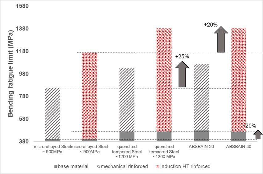
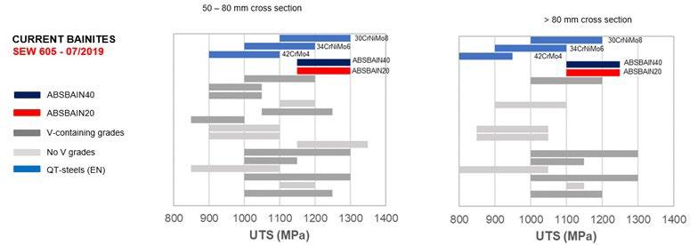
Entrambe le soluzioni sviluppate garantiscono prestazioni a fatica del 20% più elevate rispetto ai tradizionali acciai microlegati e paragonabili
ad acciai bonificati di pari livello di durezza (Fig.2). Possono essere utilizzate senza indurimento superficiale, oppure sono ottimizzate rispetti-
vamente per l’indurimento mediante deformazione plastica a freddo (ABSBAIN20) e la tempra a induzione superficiale (ABSBAIN40).
I due acciai sono stati progettati per raggiungere le proprietà meccaniche desiderate mediante raffreddamento in aria dopo deformazione plastica a caldo (laminazione oppure stampaggio), ma sono in fase di sviluppo strategie di raffreddamento dedicate
per ampliare la gamma di prestazioni ottenibili, con particolare riferimento alla resistenza allo snervamento e alla resilienza (impact test) (Fig.3). Queste includono anche processi di “Quenching & Partitioning” (Q&P), un trattamento di tempra e partizio-
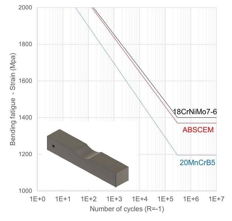

namento che permette di ottenere una struttura mista [2] con, da un lato, una martensite meno fragile, e, dall'altro, una struttura bainitica fine con una morfologia che favorisce le proprietà di duttilità [3]
ABS ha sviluppato gli acciai bainitici anche come potenziale alternativa in sostituzione degli acciai da cementazione, soprattutto quelli ternari al Nichel. La soluzione messa a punto è più economica, dal punto di vista del contenuto di elementi di lega,
rispetto ad acciai tradizionali quali il 17NiCrMo6-4 o il 18CrNiMo7-6, pur garantendo prestazioni simili a questi e quindi superiori agli acciai da cementazione al Mn-Cr (Fig.4). Grazie alla maggiore temprabilità, è inoltre adattabile a processi di cementazio-
ne “moderni” e richiede tempi inferiori di trattamento, dimostrandosi quindi una soluzione vincente anche dal punto di vista della sostenibilità.
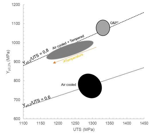
L’impegno di ABS nello sviluppo di una filiera sostenibile non si limita all’aspetto della progettazione di un acciaio dal punto di vista della sua analisi chimica, ma comprende anche lo sviluppo di processi di trasformazione dell’acciaio, in grado di conferire ad acciai “tradizionali” caratte-
ristiche microstrutturali favorevoli all’ottenimento delle proprietà richieste, ma con cicli di trasformazione a minor consumo di risorse.
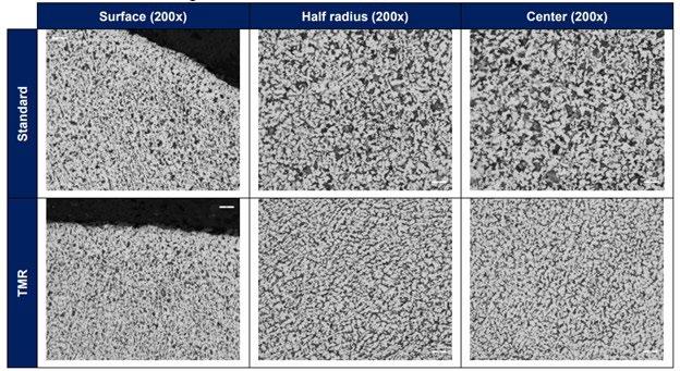
Il recente impianto di laminazione della vergella (Quality Wire Rod, Fig.5), avviato a fine 2020, è stato progettato per gestire processi di
laminazione a bassa temperatura, che, applicati ad acciai medio carbonio basso legati, quali ad esempio quelli utilizzati per applicazioni CHQ (Cold Heading Quality), conferiscono alla vergella una microstruttura più fine e più duttile (Fig.6) [4].
L’effetto di una struttura più fine, in particolare una perlite più fine, è una globulizzazione più veloce [5] e, di conseguenza, in base al tipo di acciaio, il tempo necessario al trattamento di ricottura che viene solitamente eseguito prima della formatura a freddo sarà più corto che con un processo standard.
Conclusione
In risposta alla richiesta di un’e-
voluzione sostenibile della filiera dei prodotti in acciaio, l’impegno dell’industria siderurgica è orientato non soltanto allo sviluppo tecnologico di impianti “green”, ma anche a un’evoluzione nella progettazione di acciai che sappiano garantire prestazioni elevate con minor consumo di risorse.
Acciaierie Bertoli Safau, azienda leader nella produzione di prodotti lunghi, ha risposto a questa sfida
implementando soluzioni innovative per ridurre il consumo di risorse e ridurre l’impronta di CO2 durante l'intero processo produttivo. Attraverso la sua divisione R&D, ABS Centre Métallurgique, ABS ha sviluppato acciai bainitici che forniscono elevate caratteristiche meccaniche senza la necessità di trattamento termico, un processo ad alto impatto, che consuma energia ed è una delle principali fonti di emissioni di gas serra. Gli
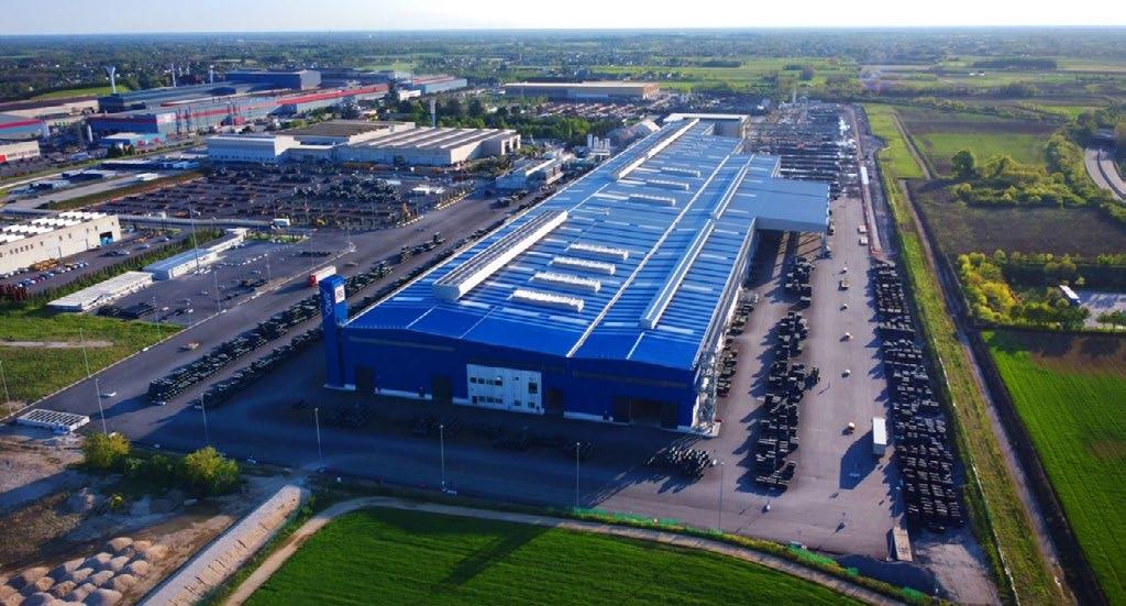
acciai bainitici hanno il potenziale per sostituire anche gli acciai da cementazione, in particolare quelli ternari al nichel, in quanto sono più economici e offrono prestazioni simili richiedendo tempi di trattamento più brevi. ABS ha inoltre sviluppato un
impianto di laminazione vergella in grado di gestire processi di laminazione a bassa temperatura, che possono essere usati per migliorare la struttura della vergella rendendo i processi di trasformazione a valle più sostenibili.
Il prossimo passo è consolidare e sviluppare queste soluzioni a livello industriale, attraverso la sinergia tra produttori e utilizzatori di componenti in acciaio.
BIBLIOGRAFIA
[1] https://themonty.com/auto-draft-20/
[2] G. Gao et al., Enhanced ductility and toughness in an ultrahigh-strength Mn–Si–Cr–C steel: The great potential of ultrafine filmy retained austenite, 2014, Acta Materialia 76 425–433
[3] J.G. Speer et al., Carbon partitioning into austenite after martensite transformation, Acta Materialia 51 (2003) 2611–2622
[4] M. Cimolino, A. Spadaccini, S. Marzio, Improvement of both mechanical properties and metallurgical microstructure of wire rod cold heading steel by applying thermo-mechanical rolling, AIM 12th International ROLLING Conference, 2022
[5] O. E. Atasoy and S. Ozbilen, "Pearlite Spheroidization," Journal of Materials Science, vol. 24, 1989, pp. 281-287.
dopo la rubrica mensile iniziata con il numero di gennaio e dedicata alle “Aziende di AIM”, in cui a rotazione i rappresentanti delle Aziende socie benemerite di AIM presentano un argomento di attualità e interesse per la propria azienda, con il numero di febbraio diamo il via ad un ulteriore nuovo appuntamento.
Da questo numero infatti, su precisa sollecitazione del Presidente AIM Silvano Panza, il professor Achille Fornasini, docente all’Università di Brescia di “Analisi Tecnica dei mercati finanziari” ed esperto proprio di mercati siderurgici e metallurgici, terrà una rubrica trimestrale dedicata ai temi economico-finanziari che coinvolgono i prodotti di cui siamo abituati ad esaminare prevalentemente gli aspetti tecnici.
Noi pensiamo che le rubrica che vi proponiamo possa suscitare l’interesse dei nostri lettori, anche coinvolgendo la curiosità di un pubblico più vasto rispetto a chi è strettamente addetto ai lavori. La conoscenza dell’argomento da parte del professor Fornasini è molto approfondita, e la sua capacità di spiegare al pubblico gli argomenti e le dinamiche dei prezzi, accompagnando il tutto con chiari grafici, porta ad una lettura piacevole e stimolante.
Buona lettura Mario CusolitoAcciaio e metalli: dinamiche, cicli e tendenze di mercato
Rubrica trimestrale a cura di Achille Fornasini
Ha insegnato all’Università Bocconi di Milano, all’Università di Venezia e all’Università di Brescia, dove è responsabile del Laboratorio per lo studio delle Dinamiche dei Sistemi e dei Mercati finanziari. Coordina l’osservatorio congiunturale di Confindustria Brescia e di ANIMA Confindustria. Partner di Sidewerb, da vent’anni cura rubriche dedicate ai mercati siderurgici e metallurgici. È autore di libri e centinaia di saggi, editoriali e articoli su temi economico-finanziari.
Questa rubrica nasce per offrire ai lettori de La Metallurgia Italiana analisi riguardanti le dinamiche dei prezzi metallurgici e siderurgici nella convinzione che esse rappresentino con efficienza, nel loro sviluppo temporale, gli effetti delle decisioni e delle aspettative di tutti coloro che partecipano a quei mercati. In altre parole, si ipotizza che nelle evoluzioni di quei particolari prezzi trovino sintesi non solo le classiche forze della domanda e dell’offerta esercitate dai produttori e dai consumatori di acciaio e di metalli, ma anche le azioni e le aspettative di una ben più ampia pluralità di operatori - commercianti, speculatori finanziari, arbitraggisti, ecc. - detentori di specifiche informazioni, conoscenze e competenze. L’accurato studio degli andamenti dei prezzi degli elementi basilari e dei semilavorati tipici delle produzioni di acciaio a ciclo integrale e a forno elettrico, nonché delle quotazioni dei metalli non ferrosi, può dunque consentire di ottenere indicazioni utili all’individuazione ed alla qualificazione delle diverse fasi cicliche e tendenziali dei mercati siderurgici e metallurgici.
Il contesto generale
Anticipando gli approfondimenti, ritengo utile rammentare le ripercussioni sui mercati generate in questi ultimi tre anni dalla pandemia, dalla crisi energetica e dal conflitto russo-ucraino. La corsa agli accaparramenti di materie prime avviata dalla Cina, uscita per prima dalla fase di lockdown nel 2020, e il successivo rapido recupero della produzione industriale globale hanno innescato

il persistente accrescimento delle scorte nei magazzini a monte e a valle delle imprese di tutto il mondo. Nella seconda parte del 2020 e per l’intero 2021 le imprese, nell’attesa di una continua espansione della domanda di materie prime e di semilavorati, hanno tentato di anticipare i conseguenti rincari dei prezzi con l’unico risultato di seguitare a rinfocolarli. Sostenuto anche dalle abnormi immissioni di liquidità derivanti dalle manovre promosse dai governi e dalle banche centrali per sostenere le economie, l’accumulo di scorte è proseguito fino al primo trimestre 2022 quando i primi segnali di un’inflazione potenzialmente esplosiva, le angustie provocate dalla guerra, l’approccio zero-Covid in Cina e il radicale cambiamento delle politiche monetarie in USA e in Europa, con il conseguente impatto sul costo del denaro, hanno ribaltato le aspettative dei partecipanti ai mercati. Il crescente pessimismo sulle prospettive economiche e il conseguente riadattamento delle politiche di acquisto delle imprese alle mutate condizioni di contesto hanno orientato al ribasso i prezzi delle materie prime.
La produzione di acciaio a ciclo integrale
In questo primo appuntamento ci occupiamo esclusivamente della filiera della produzione d’acciaio a ciclo integrale, tentando di stabilire le più significative colleganze tra i mercati e gli accadimenti economici generali sopra ricordati. Si consideri al riguardo la figura 1, che illustra gli andamenti medi settimanali in dollari/tonnellata dei prezzi del minerale di ferro CFR North China (scala
di destra) e del carbone metallurgico FOB Australia (scala di sinistra). Alla scala di destra si riferisce anche la dinamica del valore “core” della carica d’altoforno, ovvero l’esito di un calcolo basato esclusivamente sui contributi
ponderati del minerale e del coke, escludendo dunque gli apporti della componente energetica e delle spese generali.
Come si può osservare, la Cina avvia il movimento rialzista dei prezzi del minerale nel mese di febbraio 2020, che accelera grazie ai massicci acquisti via via provenienti da ogni angolo del pianeta. La storica ascesa si esaurisce tra i mesi di maggio e luglio 2021 (+176% dai minimi con un massimo a 233,10 dollari/tonnellata il 12 maggio) quando negli operatori prendono il sopravvento lo scetticismo e la sfiducia. Segue la rapida contrazione della domanda e il conseguente tracollo dei prezzi del minerale culminante a metà novembre dello stesso anno (-60,2%). Prende poi corpo una nuova fase ascendente dei prezzi, che acquista velocità in concomitanza della crisi geopolitica est-europea, registrando il suo top nel mese di marzo dello scorso anno (+77%). Che si trattasse di uno spunto effimero è dimostrato dalla successiva caduta che, agli inizi di novembre, riporta le quotazioni sui minimi del 2020 (-47,7%) in prossimità dei costi di produzione delle società minerarie meno efficienti. Il conseguente riequilibrio del mercato, dovuto ai tagli dell’offerta e al riaffacciarsi di una timida domanda, facilita il recupero dei prezzi, che si riportano al rialzo (+49,6% a metà febbraio 2023), lasciando peraltro presagire una fase correttiva
lungo una tendenza ascendente sostenuta dalla graduale riapertura dell’economia cinese.
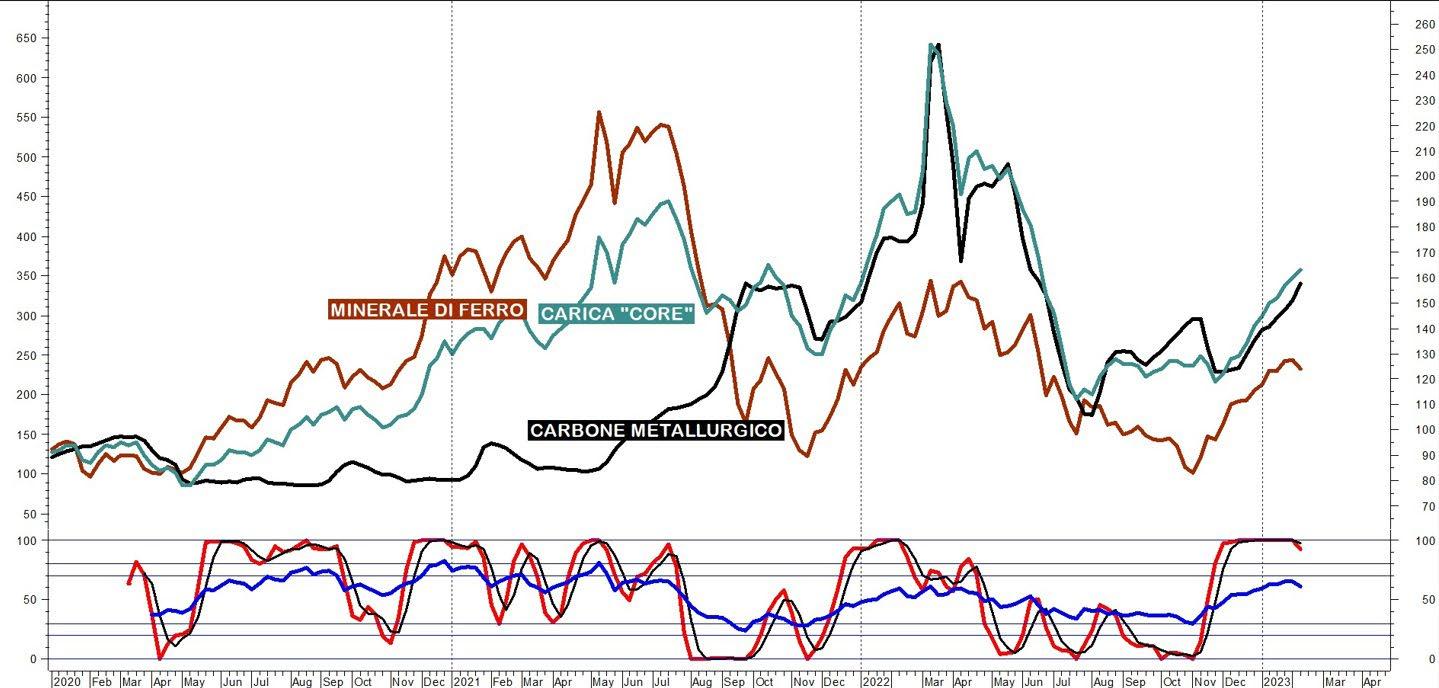
Passando ai prezzi del carbone metallurgico, nell’ultimo triennio si osserva uno sviluppo differente: dopo la fase stazionaria durata per tutto il 2020 e per l’intero primo semestre 2021, la curva risale speditamente fino alla metà di marzo 2022, raggiungendo un massimo storico a quota 642 dollari/tonnellata (+649% dai minimi 2020!). Dopodiché i prezzi si orientano al ribasso, accompagnando il contestuale calo del minerale fino al mese di agosto dello scorso anno (-72,7%), quando inizia una risalita tuttora in corso: +94,4% a metà febbraio 2023.
Il valore di carica risente in misura maggiore, ovviamente, dell’andamento del minerale, anche se raggiunge il suo top (+223% dai minimi del 2020) in concomitanza del picco del coke per poi declinare fino a luglio dello scorso anno (-55,5%) e infine riprendersi, intercettando i recuperi dei due materiali basilari (+45,5%): un orientamento che appare destinato a continuare, anche se la posizione assunta dalle curve tecniche poste a piè di grafico lascia presagire, nel breve termine, temporanee correzioni destinate a riequilibrare i mercati degli elementi basilari
del ciclo integrale.
In una prospettiva di medio-lungo termine, invece, i mercati del minerale di ferro e del coke risentiranno presumibilmente della progressiva contrazione delle produzioni da altoforno e della contestuale maggior crescita dei processi produttivi meno inquinanti tipici dell’elettrosiderurgia. Se non interverranno drastici tagli dell’offerta, la conseguente minor domanda dei due elementi basilari non potrà dunque che portare a ribassi dei prezzi, che nel prossimo quinquennio potrebbero stabilizzarsi su medie annuali inferiori a quelle archiviate nel 2021 e nel 2022.
I semilavorati siderurgici
La dinamica dei prezzi del minerale di ferro guida l’andamento delle quotazioni dei semilavorati tipici del ciclo integrale dell’acciaio come i laminati piani destinati alla produzione di lamiere. Si osservi al riguardo la figura 2 che illustra gli andamenti delle quotazioni medie settimanali in dollari/tonnellata dei coils resi FOB Shanghai e FOB Black Sea: la durata dei rialzi coincide infatti fino
al mese di maggio 2021 (+156,5% il benchmark cinese, +199% il riferimento est-europeo) quando inizia a contrarsi la domanda internazionale di prodotti piani. È il preludio alla susseguente flessione dei prezzi, che si arresta nel mese di gennaio 2022 (-26% i prezzi Shanghai, -27,5% i prezzi Black Sea), quando due nuovi movimenti rialzisti evidenziano una diversa estensione: mentre i valori del Dragone mettono a segno un contenuto recupero (+16,7%), le quotazioni europee spiccano il volo per effetto delle tensioni generate dallo scoppio del conflitto russo-ucraino (+51,7%). Entrambe le curve tornano a declinare durante l’ultima settimana di marzo dello scorso anno, raggiungendo in pochi mesi i livelli registrati nel quarto trimestre 2020: le quotazioni Black Sea toccano il fondo a settembre (-55,5%), mentre quelle cinesi li fissano a novembre (-41,2%) nell’ambito di una fluttuazione laterale che si esaurisce nel dicembre 2022. I due movimenti si ripropongono infine concordemente al rialzo con esiti a metà febbraio compresi tra il +23,8% dei pezzi cinesi e il +33,6% dei prezzi est-europei.
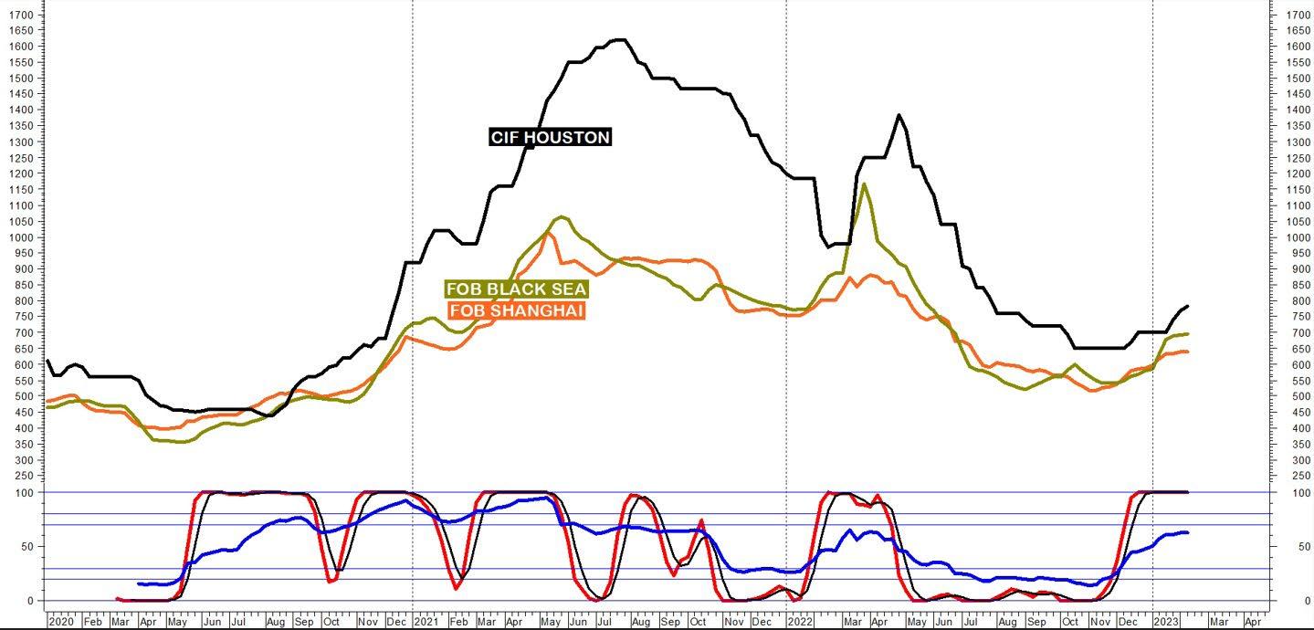
In figura 2 è compresa anche la dinamica dei prezzi CIF Houston che per l’intero 2021 e per buona parte dell’anno successivo si posiziona su livelli molto più elevati di quelli stabiliti dagli altri mercati come conseguenza delle barriere commerciali e dell’autarchia imposte politica-
mente alle produzioni statunitensi. Peraltro, l’andamento della curva si dimostra molto concordante con le altre: dopo il primo balzo esauritosi a luglio 2021 (+268%), i prezzi flettono fino a febbraio 2022 (-40,2%) per poi risalire (+43% a maggio) e ridiscendere (-53% a dicembre).
Dopodiché la curva torna ad allinearsi con le altre, esprimendo attualmente un recupero in via di ulteriore espansione (+20,3%).
Le produzioni nazionali
Concludiamo l’analisi con la figura 3, che illustra gli andamenti dei prezzi dei principali prodotti piani quotati a livello nazionale e rilevati settimanalmente in euro/ tonnellata da Siderweb. Si noti come le quattro curve di prezzo siano fortemente concordanti non solo tra di esse, ma anche con le evoluzioni dei benchmark internazionali proposti nella figura 2. Limitando per semplicità l’analisi dal mese di gennaio 2022, si constata come i quattro movimenti si impennino simultaneamente in concomitanza dello scoppio della guerra in Ucraina con i prezzi delle lamiere da treno in forte rialzo fino al mese di aprile, per i timori dell’emergenza di un’offerta insufficiente (+112,3%), a guidare nello stesso senso le quotazioni dei coils (+47,4%), delle lamiere nere (+46,5%)
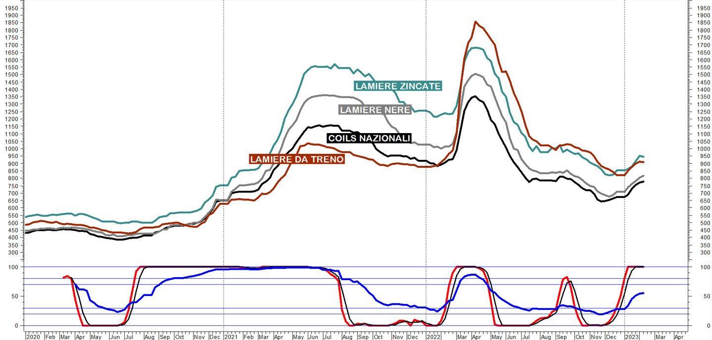
e delle lamiere zincate (+34%). Seguono mesi di persistenti ribassi, che si esauriscono a fine novembre (coils -52,5%), a inizio dicembre (lamiere nere -55,1%, lamiere zincate -51,2%) e a fine dicembre (-55,7% lamiere da treno). Di recente si assiste al ritorno dei rialzi anticipati come di consueto dalla dinamica dei coils (+21,2% a metà febbraio): +10,7% le lamiere da treno, +15,2% le lamiere zincate, +20,8% le lamiere nere.
L’analisi degli indicatori tecnici posti a piè di grafico conferma la sussistenza di un ulteriore potenziale rialzista che, pur non potendosi escludere storni temporanei, prefigura la continuazione della corrente fase ascendente, a sua volta indirizzata dalle tendenze delle produzioni internazionali.
Nei prossimi appuntamenti di questa rubrica indagheremo i mercati degli elementi basilari, dei semilavorati e dei prodotti finiti tipici delle produzioni di acciaio a forno elettrico (maggio), dei metalli non ferrosi (agosto), per sintetizzare infine l’annata e delineare le possibili linee di sviluppo delle tre filiere per l’anno successivo (dicembre). Per domande e confronti: achille.fornasini@unibs.it
Eventi AIM / AIM events
CONVEGNI
ECHT 2023 EUROPEAN CONFERENCE HEAT TREATMENT & SURFACE ENGINEERING – Genova, 29-31 maggio 2023
XV GIORNATE NAZIONALI CORROSIONE E PROTEZIONE - Torino, 5-7 luglio 2023 http://www.aimnet.it/gncorrosione/
S2P 2023 INTERNATIONAL CONFERENCE ON SEMISOLID PROCESSING OF ALLOYS AND COMPOSITES –Brescia, 6-8 settembre 2023 http://www.aimnet.it/s2p/
International Meeting EAF: PRODUCTIVITY, ENERGY EFFICIENCY, RAW MATERIALS AND DECARBONIZATION – 16-17 novembre
International Workshop on HIGH STRENGTH STEELS – Bergamo, 30 novembre-1 dicembre
CORSI E GIORNATE DI STUDIO
Corso METALLURGIA DI BASE PROPEDEUTICO AI TRATTAMENTI TERMICI (TTM) – Milano, 7-8 - Webinar
FaReTra, 16-17 marzo
Giornata di Studio VERIFICA E MANUTENZIONE DI STRUTTURE METALLICHE STORICHE – Milano, 9 marzo
Corso CREEP – Modulo AVANZATO – Milano, 15 marzo
Giornata di Studio PROCESSI POST STAMPA ADDITIVA: DAL DESIGN DEL CICLO DI PRODUZIONE AL MANUFATTO – c/o TAV Vacuum Furnaces, 18 aprile e c/o GFM, 19 aprile
Corso FAILURE ANALYSIS – ibrido, 16-17-23 maggio
Giornata di Studio DUPLEX E SUPERDUPLEX: FILIERA DI PRODUZIONE E NETWORKING – 18-19 maggio
Giornata di Studio I LAMINATI DI ALLUMINIO: APPLICAZIONI E INNOVAZIONI – c/o Laminazione sottile, 19 maggio
Corso RIVESTIMENTI – I MODULO RIVESTIMENTI SOTTILI – Rivoli c/o Anton Paar Italia 8-9 giugno
Giornata di Studio SOSTENIBILITÀ NELLA PRODUZIONE DI COMPONENTI MECCANICI – 21 giugno
Giornata di Studio METALLO DURO – 13-15 settembre
Giornata di Studio CARATTERIZZAZIONE FUNZIONALE DI SUPERFICI MODIFICATE - novembre
Giornata di Studio PALLINATURA E DIFFRATTOMETRIA RX – Agrate Conturbia (NO) c/o GNR, novembre
FaReTra (Fair Remote Training) - FORMAZIONE E AGGIORNAMENTO A DISTANZA
Modalità Asincrona (registrazioni)
Giornata di Studio ASPETTI E GESTIONE DELLA NORMATIVA NEL CAMPO DEI TRATTAMENTI TERMICI
Per ulteriori informazioni rivolgersi alla Segreteria AIM, e-mail: info@aimnet.it, oppure visitare il sito internet www.aimnet. it
Corso PROVE NON DISTRUTTIVE
Giornata di Studio TRATTAMENTI SUPERFICIALI SU ALLUMINIO, A SCOPO DECORATIVO E PROTETTIVO
Corso Modulare METALLOGRAFIA – I MODULO, II MODULO “METALLI NON FERROSI”
Corso modulare FONDERIA PER NON FONDITORI
Corso TRIBOLOGIA INDUSTRIALE – I MODULO
Giornate di Studio GETTI PRESSOCOLATI PER APPLICAZIONI STRUTTURALI
Corso DIFETTOLOGIA NEI GETTI PRESSOCOLATI: METALLIZZAZIONI
Corso ADDITIVE METALLURGY
Corso METALLURGIA PER NON METALLURGISTI
Giornata di Studio PRESSOCOLATA IN ZAMA
Giornata di Studio LA SFIDA DELLA NEUTRALITÀ CARBONICA
Corso itinerante METALLURGIA SICURA
Corso modulare TRATTAMENTI TERMICI
Corso modulare I REFRATTARI E LE LORO APPLICAZIONI
Corso GLI ACCIAI INOSSIDABILI 11ª edizione
Corso FAILURE ANALYSIS 11a edizione
Giornata di Studio PERFORMANCE E DEGRADO DEI MATERIALI METALLICI UTILIZZATI IN CAMPO EOLICO: CAPIRE PER PREVENIRE
L’elenco completo delle iniziative è disponibile sul sito: www.aimnet.it
(*) In caso non sia possibile svolgere la manifestazione in presenza, la stessa verrà erogata a distanza in modalità webinar
Comitati tecnici / Study groups
CT METALLURGIA FISICA E SCIENZA DEI MATERIALI (MFM) (riunione del 20 dicembre 2022)
Consuntivo di attività svolte
• La GdS “EBSD: come e perché” si è svolta in presenza ad Aosta il 13 ottobre 2022 presso Cogne Acciai Speciali con la partecipazione di 50 iscritti, molto soddisfacente soprattutto perché più della metà provenienti da aziende. Nel corso della giornata si sono svolte delle dimostrazioni con esempi di acquisizione dati e processing dei dati tramite collegamento con i laboratori OXFORD in UK, cosa molto apprezzata dai partecipanti. L’esame dei questionari di soddisfazione ha evidenziato un forte gradimento per la presenza in aula oltre che un interessante suggerimento per l’approfondimento della tematica della tessitura cristallografica nei metalli.
Manifestazioni in corso di organizzazione
• La GdS “Tecniche sperimentali per la caratterizzazione dei materiali” si terrà a Vicenza il 23 febbraio 2023. Viene presentato il programma per l’intera giornata che copre argomenti di metallografia, microscopie elettroniche, spettroscopia meccanica, spettroscopie per l’analisi delle superfici, nanoindentazione e analisi termica. La locandina dell’evento sarà distribuita a breve.
• La presidente Paola Bassani illustra il programma della GdS “I metalli e lo scambio termico: nuovi trend” programmata per il 24 gennaio 2023 presso la sede Bovisa del Politecnico di Milano. I principali temi saranno relativi all’aumento dell’efficienza dello scambio termico e all’utilizzo di tecnologie per la conversione del calore in altre forme di energia.
• Bassani comunica che Tuissi organizzerà l’evento ESOMAT 2024 - European Symposium on Martensitic Transformations a Lecco dal 26 al 30 agosto 2024. Si tratta di un simposio internazionale con cadenza triennale che coinvolge CNR-ICMATE, Università della Calabria e AIM.
Iniziative future
• Il coordinatore Montanari conferma che il corso sulla solidificazione si terrà nella seconda metà del 2023.
• Il coordinatore Donnini comunica che il corso su “Tenacità e resistenza a fatica dei materiali metallici” si terrà nella primavera 2023, probabilmente presso la sede CNR di Milano. Ci saranno presentazioni da parte di rappresentanti del CT Controllo e Caratterizzazione dei Prodotti e dell’Istituto Italiano di Saldatura.
CT ACCIAIERIA (A)
CT FORGIATURA (F)
(riunione congiunta del 17 gennaio 2023)
Notizie dal Comitato
• Pierandrea Galli di Forge Fedriga entra a far parte del CT Forgiatura in sostituzione di Domenico Del Vecchio, in pensione.
• Manuele Dabalà, Professore Ordinario presso il Dipartimento di Ingegneria Industriale dell'Università di Padova, da poco entrato nel CT Acciaieria, si presenta brevemente.
Manifestazioni in corso di organizzazione
• Rampinini condivide la prima bozza di programma per la GdS “ITER experience for new DTT Enea Fusion Reactor” che si svolgerà in due giornate: una prima a Roma a settembre 2023 e la seconda a Cadarache in ottobre 2023. La bozza sarà fatta circolare tra i membri del CT per la raccolta di ulteriori contributi.
• I coordinatori Lissignoli e Saleri presentano e illustrano il programma delle due GdS “Duplex e superduplex: filiera di produzione e networking (esperienze nella produzione, trasformazione ed utilizzo degli acciai inossidabili bifasici. La sede sarà definita nel bresciano per i giorni 18 e 19 maggio 2023.
Iniziative future
• Per il corso “Macchina fusoria” Mapelli chiede disponibilità alle aziende ad ospitare le giornate e sollecita temi da trattare. Si propone di parlare di stirrer, iniezione di polimeri, biochar.
• Anche Rampinini chiede ai membri del CT idee e proposte per il Corso
CT MATERIALI PER L’ENERGIA (ME)
(riunione telematica del 26 gennaio 2023)
Consuntivo di attività svolte
• La GdS “I metalli e lo scambio termico: nuovi trend - Approcci innovativi per scambiatori di calore e gestione del calore” si è tenuta a Milano (Campus Bovisa) il 24 gennaio 2023. La coordinatrice Gariboldi è soddisfatta per l’alto livello della qualità degli interventi e per la proficua discussione tra metallurgisti ed impiantisti provenienti dalle aziende. I questionari di soddisfazione compilati dai partecipanti evidenziano un’ottima valutazione dei relatori e della loro competenza.
• Corso “Creep”: il 17 e 18 gennaio si è tenuto a Milano presso la sede del CNR il Modulo base del corso Creep. Il numero di partecipanti è in linea con le ultime edizioni del corso. Si è registrato qualche problema alla distribuzione delle dispense del corso, in quanto non tutti i relatori sono stati disponibili a lasciare materiale proprietario. Tutti i partecipanti hanno poi seguito la visita ai laboratori. Buona parte di essi si è iscritta anche al modulo avanzato.
Iniziative future
• Manifestazioni su “Stesura specifiche” e “Materiali per nucleare”: le due iniziative risultano in qualche modo collegate, anche a seguito dei contatti e della collaborazione che si è instaurata tra il nostro CT ME e il CT Forgiatura, che sta organizzando l’evento “ITER: experience for new DTT Enea Fusion Reactor”.
• Pinciroli, coordinatore della manifestazione su stesura specifiche, ritiene che alcuni degli interventi di ITER potrebbero essere presentati alla giornata AIM dedicata alla stesura delle specifiche, di cui sta consolidando la scaletta che viene presentata ai presenti nella sua stesura più aggiornata.
• GdS su materiali per fissione nucleare: il coordinatore Ripamonti ha già avuto diversi contatti e farà circolare una bozza del programma appena pronto, possibilmente entro la fine di aprile. La manifestazione si dovrebbe tenere in giugno-luglio 2023.
CT CORROSIONE (C)
(riunione del 27 gennaio 2023)
Notizie dal Comitato
• Ad inizio riunione si sono tenute le elezioni per il rinnovo delle cariche all’interno del CT. Tutte le precedenti cariche sono state confermate fino al 2025: Presidente Prof. Fabio Bolzoni, Vicepresidente Prof.ssa Marina Cabrini, Segretario Prof. Tiziano Bellezze.
Manifestazioni in corso di organizzazione
• Il presidente Bolzoni ricorda che nei giorni 7-8-9 febbraio 2023 presso l’Università di Ferrara si terrà la “Scuola Cecilia Monticelli - Tecniche elettrochimiche per lo studio della corrosione”. Bassani comunica che ci sono quasi 60 iscritti. Viene proposto di ripetere questa scuola ogni 2 anni, e di organizzare altre scuole e in particolare una sui fenomeni sull’environmental assisted cracking. Questo tipo di scuole, destinate principalmente a dottorandi, dovrebbero essere riconosciute dai corsi di dottorato di varie Università assegnando ai partecipanti i crediti formativi.
• XV Giornate Nazionali sulla Corrosione e Protezione (Torino – 5-7 luglio 2023). Sono state ricevute circa 60 memorie (erano 63 nella precedente edizione online). Tutte le sessioni del convegno si svolgeranno presso la sede centrale del Politecnico di Torino perché il Castello del Valentino, che doveva ospitare l’evento, ha dei limiti di capienza imposti dalle autorità. Sono stati definiti i relatori della sessione plenaria e una key-note nella sessione beni culturali. Viene presentata una bozza di programma che sarà fatta girare tra i membri del CT per eventuali modifiche e suggerimenti. Sono state definite anche le attività collaterali, quali l’aperitivo di benvenuto, la cena di gala alla Reggia di Venaria ed un eventuale tour nelle Langhe per sabato 8 luglio. La Rivista “La Metallurgia Italiana” pubblicherà due numeri dedicati a questo evento nel corso del 2023.
Iniziative future
• Bolzoni invita i membri del CT C a considerare l’idea di riprendere il corso di corrosione classico, organizzato negli anni precedenti. Inoltre, ricorda che si potrebbe considerare anche un corso di corrosione con le prove standard, più finalizzato a chi viene dall’industria, come ipotizzato in precedenti riunioni.
Iniziative future
CT METALLI E TECNOLOGIE APPLICATIVE (MTA)
(riunione telematica del 01 febbraio 2023)
• GdS sulla sostenibilità ambientale nel campo delle costruzioni civili: il Dott. Loconsolo sta procedendo con la preparazione della giornata trovando gli opportuni docenti. La Dott. Bassani porta la discussione sui crediti formativi: l’AIM non può erogarli, è necessario rivolgersi ad altri enti, come FAST o CTA (Collegio dei Tecnici dell’Acciaio) con cui metterà in contatto il dr. Loconsolo anche per verificare se vi sia un interesse a collaborare all’iniziativa, soprattutto per la parte sulla progettazione in acciaio.
• GdS sulla Saldatura: i presenti concordano che, rispetto al taglio originale, il programma vada ripensato completamente, per esempio concentrandosi sulla saldatura degli acciai alto-resistenziali (inclusi inox martensitici) e per applicazioni particolari quali quelli per alte e basse temperature. Si potrebbe anche introdurre il tema delle riparazioni. Diversi membri del CT si attiveranno nei prossimi giorni per trovare potenziali relatori su questi temi.
• GdS sui metalli nei motori elettrici: Per quanto riguarda i metalli impiegati nei motori elettrici, Morri ha contattato diversi produttori di motori elettrici, di lamierini magnetici e di polveri per materiali magnetici da sinterizzazione, ottenendo risposte positive circa la partecipazione come relatori. Restano da contattare aziende legate al settore del rame e qualcuno legato alla progettazione. La manifestazione potrebbe essere organizzata presso l’Università di Bologna a settembre 2023.
CENTRO RIVESTIMENTI E TRIBOLOGIA (R)
(riunione del 02 febbraio 2023)
Manifestazioni in corso di organizzazione
• Corso “Rivestimenti” – primo modulo “Film sottili”: viene commentata e discussa la scaletta preparata su un file condiviso online. Nello specifico si discute della disponibilità dei relatori, della completezza degli interventi e di eventuali altri argomenti da trattare non ancora messi a punto. Viene anche definita la durata dei vari interventi che sarà in genere di 30 minuti salvo le lezioni di base che saranno di 45 minuti. Il corso rimane per ora fissato nei giorni 14 e15 giugno 2023 e sarà erogato solo in presenza, a meno di numerose richieste per partecipazione a distanza.
Iniziative future
• Corso sulla caratterizzazione delle superfici: dopo le discussioni della precedente riunione, il presidente Bolelli farà circolare un foglio condiviso online per raccogliere le proposte da discutere nella prossima riunione.
Normativa / Standards
Norme pubblicate e progetti in inchiesta (aggiornamento 13 gennaio 2023)
Norme UNSIDER pubblicate da UNI nel mese di gennaio 2023
UNI EN ISO 1179-2:2023
Raccordi per impieghi generali e per trasmissioni oleoidrauliche e pneumatiche - Bocche e maschi d'estremità con filettature ISO 228-1 e tenuta mediante elastomero o metallo su metallo - Parte 2: Maschi d'estremità serie pesante (Serie S) e serie leggera (Serie L) con tenuta mediante elastomero (Tipo E)
Progetti UNSIDER messi allo studio dal CEN (Stage 10.99) –febbraio 2023
EN ISO 13680:2020/prA1
Petroleum and natural gas industries
- Corrosion-resistant alloy seamless tubular products for use as casing, tubing, coupling stock and accessory material - Technical delivery conditionsAmendment 1
prEN ISO 14719 rev
Chemical analysis of refractory material glass and glazes - Determination of Fe2+ and Fe3+ by the spectral photometric method with 1,10-phenanthroline
prEN ISO 4937 rev
Steel and iron - Determination of chromium content - Potentiometric or visual titration method
prEN ISO 9658 rev
Steel - Determination of aluminium content - Flame atomic absorption spectrometric method
prEN ISO 10714 rev
Steel and iron - Determination of phosphorus content - Phosphovanadomolybdate spectrophotometric method
prEN 10205 rev
Cold reduced tinmill products – Blackplate
Progetti UNSIDER al voto FprEN e ISO/FDIS – febbraio 2023
prEN – progetti di norma europei
prEN ISO 19901-5
Petroleum and natural gas industries - Specific requirements for offshore structures - Part 3: Topsides structure (ISO/DIS 19901-3:2022)
prEN ISO 13702
Petroleum and natural gas industries - Control and mitigation of fires and explosions on offshore production installations - Requirements and guidelines (ISO/DIS 13702:2022)
prEN ISO 13520
Determination of ferrite content in austenitic stainless steel castings (ISO/DIS 13520:2022)
ISO/DIS – progetti di norma internazionali
ISO/DIS 13702
Petroleum and natural gas industries — Control and mitigation of fires and explosions on offshore production installations — Requirements and guidelines
ISO/DIS 11973
Heat-resistant cast steels and alloys for general applications
ISO/DIS 11972
Corrosion-resistant cast steels for general applications
ISO/DIS 9477
High strength cast steels for general engineering and structural purposes
ISO/DIS 6819
Steel wire rod for bridge cable wire
ISO/DIS 4993
Steel and iron castings — Radiographic testing
ISO/DIS 4990
Steel castings — General technical delivery requirements
ISO/DIS 3845
Oil and gas industries including lower carbon energy — Full ring ovalization test method for the evaluation of the cracking resistance of steel line pipe in sour service
Progetti UNSIDER al voto FprEN e ISO/FDIS – febbraio 2023
FprEN – progetti di norma europei
Fpr EN ISO 10113
Metallic materials - Sheet and stripDetermination of plastic strain ratio (ISO/ FDIS 10113:2019)
ISO/FDIS – progetti di norma internazionali
ISO/FDIS 14556
Metallic materials — Charpy V-notch pendulum impact test — Instrumented test method
DUPLEX E SUPERDUPLEX: FILIERA DI PRODUZIONE E NETWORKING


ESPERIENZE NELLA PRODUZIONE, TRASFORMAZIONE ED UTILIZZO DEGLI ACCIAI INOSSIDABILI BIFASICI
Filiera, networking ed esperienza: sono tre concetti molto importanti in qualsiasi ambito produttivo.

L’Associazione Italiana di Metallurgia ha cercato di concentrare questi tre aspetti in due incontri dedicati alla produzione di acciai Duplex e Superduplex.


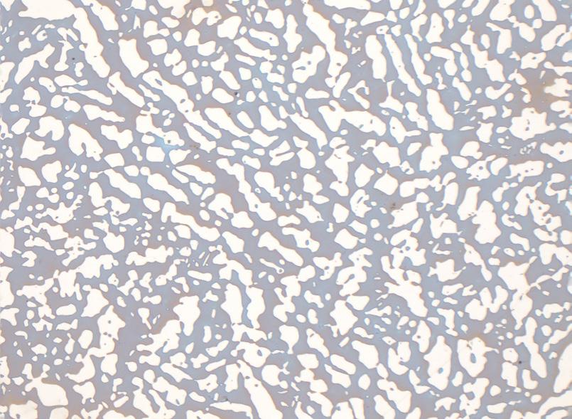
Entrambe le Giornate di Studio, dedicate agli acciai inossidabili bifasici, ospiteranno professionisti altamente qualificati nel settore metallurgico, che descriveranno la propria esperienza sul campo, partendo dalla produzione in acciaieria, ai processi di deformazione plastica a caldo, alle normative e collaudi ed impiego finale.
Si parlerà di casi concreti, lasciando ampio spazio anche a dibattiti, domande e confronti tecnici.
Questa iniziativa, inoltre, permetterà ai partecipanti di condividere informazioni ed accrescere le proprie relazioni con altri professionisti del settore.
Le due giornate sono dedicate ai tecnici, ricercatori, professionisti e in generale agli operatori del settore che abbiano voglia di ascoltare e condividere le esperienze lavorative svolte ad un miglioramento individuale ed aziendale.
Segreteria organizzativa
Via F. Turati, 8
20121 Milano
Tel. +39 0276397770
e-mail: info@aimnet.it
www.aimnet.it
