Italiana
International Journal of the Italian Association for Metallurgy
n. 09 settembre 2022
Organo ufficiale dell’Associazione Italiana di Metallurgia.
Rivista fondata nel 1909
La Metallurgia Italiana
International Journal of the Italian Association for Metallurgy
Organo ufficiale dell’Associazione Italiana di Metallurgia. HouseorganofAIMItalianAssociationforMetallurgy. Rivista fondata nel 1909
Direttore responsabile/Chiefeditor: Mario Cusolito
Direttore vicario/Deputydirector: Gianangelo Camona
Comitato scientifico/Editorialpanel: Marco Actis Grande, Silvia Barella, Paola Bassani, Christian Bernhard, Massimiliano Bestetti, Wolfgang Bleck, Franco Bonollo, Irene Calliari, Mariano Enrique Castrodeza, Emanuela Cerri, Vlatislav Deev, Andrea Di Schino, Donato Firrao, Bernd Kleimt, Carlo Mapelli, Denis Jean Mithieux, Roberto Montanari, Marco Ormellese, Mariapia Pedeferri, Massimo Pellizzari, Barbara Previtali, Evgeny S. Prusov, Dario Ripamonti, Dieter Senk
Segreteria di redazione/Editorialsecretary: Marta Verderi
Comitato di redazione/Editorialcommittee: Federica Bassani, Gianangelo Camona, Mario Cusolito, Carlo Mapelli, Federico Mazzolari, Marta Verderi, Silvano Panza
Direzione e redazione/Editorialandexecutiveoffice: AIM - Via F. Turati 8 - 20121 Milano tel. 02 76 02 11 32 - fax 02 76 02 05 51 met@aimnet.it - www.aimnet.it
Immagine in copertina: Shutterstock
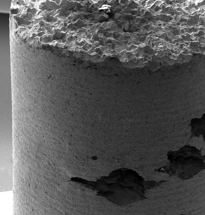
Immagine in copertina: Corrosione per vaiolatura e frattura fragile di un acciaio inossidabile martensitico in soluzione di NaCl contenente tiosolfati Pitting corrosion and brittle failure of martensitic stainless steel in a thiosulphate containing NaCl solution
Gestione editoriale e pubblicità Publisher and marketing office: siderweb spa Via Don Milani, 5 - 25020 Flero (BS) tel. 030 25 400 06 - fax 030 25 400 41 commerciale@siderweb.com - www.siderweb.com

La riproduzione degli articoli e delle illustrazioni è permessa solo citando la fonte e previa autorizzazione della Direzione della rivista. Reproduction in whole or in part of articles and images is permitted only upon receipt of required permission and provided that the source is cited.
Reg. Trib. Milano n. 499 del 18/9/1948. Sped. in abb. Post. - D.L.353/2003 (conv. L. 27/02/2004 n. 46) art. 1, comma 1, DCB UD
siderweb spa è iscritta al Roc con il num. 26116
n.09 settembre 2022 Anno 113 - ISSN 0026-0843
Editoriale / Editorial Editoriale
A cura di Edoardo Proverbio................................................................................................................ pag.04
Memorie scientifiche / Scientific papers Corrosione / Corrosion
Tailoring superhydrophobic surfaces on AA6082 aluminum alloy by etching in HF/HCl solution for enhanced corrosion protection A.Khaskhoussi, L. Calabrese, E. Proverbio pag.08
Microstructural and electrochemical characterization of dissimilar joints of aluminum alloy AW5083 and carbon steel S355 obtained by friction welding A.Khaskhoussi, G. Di Bella, C. Borsellino, L. Calabrese, E. Proverbio.......................................................... pag.15
Effect of macro and microstructural features on the corrosion behavior of additively manufactured Alloy 625 F. Carugo, M. Cabrini, A. Carrozza, S. Lorenzi, T. Pastore, G. Barbieri, F. Cognini, M. Moncada ............. pag.22
Attualità industriale / Industry news
nd i ce
Effect of multi-pass cold rolling on the corrosion properties of 2101 duplex stainless steel edited by : L. Pezzato, C. Gennari, A.G. Settimi, I. Calliari, A. Kemény, I. Mészáros pag.31
Field experience - Localized corrosion behavior of lean duplex stainless steel DX2202 in urban wastewater treatment plants edited by: A. Allion, C. David, B. Emo, N. Larché.............................................................................. pag.37
Stato dell’arte sulle tecniche industriali per il recupero dei fanghi di decapaggio nel processo degli acciai inossidabili a cura di: C. Tirasso, C. Rocchi, K. Brunelli........................................................................................................ pag.48
Industrial techniques for recovery of stainless steel pickling sludge: a review edited by: C. Tirasso, C. Rocchi, K. Brunelli.................................................................................. .... pag.57
Atti e notizie / AIM news
Medaglia Cavallaro al Prof. Luciano Lazzari pag.65
Tough Steel Project pag.67 Eventi AIM / AIM events pag.69 Comitati tecnici / Study groups pag.71 Normativa / Standards pag.75
“L’introduzione di nuove tecnologie e le spinte determinate dalla necessità di accelerare la transizione energetica nei diversi settori produttivi ci pone di fronte a scenari ancora inesplorati e a problematiche di durabilità tuttora da affrontare”.
"The introduction of new technologiesandthe pressuresdeterminedby the need to accelerate the energytransitioninthe various production sectors place us in front of still unexplored scenarios and durabilityissuesstilltobe addressed".
LE PROBLEMATICHE DELLA CORROSIONE IN
UN MONDO CHE CAMBIA
Questo numero de “La Metallurgia Italiana” è dedicato alla corrosione dei materiali. È il secondo numero dell’anno 2022 che ospita lavori dedicati alle problematiche del degrado dei materiali metallici nei più disparati ambiti dell’ingegneria, a dimostrazione di quanto tali aspetti siano di continua e rilevante importanza in tutti settori dell’ingegneria. In particolare sono inclusi in questo numero alcuni lavori che sono stati presentati all’ESSC & DUPLEX 2022 (11th European Stainless Steel Conference Science & Market e 7th European Duplex Stainless Steel Conference & Exhibition) organizzati congiuntamente a Bardolino (Verona) lo scorso giungo e altri che saranno presentati al 39° Convegno Nazionale AIM che si è tenuto a Padova il 21-23 settembre. Sebbene la comprensione dei fenomeni corrosionistici sia notevolmente avanzata in questi ultimi decenni grazie all’impegno sempre crescente di ricercatori a livello globale e all’avanzamento tecnologico che ha messo a disposizione apparecchiature sempre più sofisticate, le
THE PROBLEMS OF CORROSION IN
A CHANGING WORLD
This issue of “La Metallurgia Italiana” is dedicated to the corrosion of materials. It is the second issue of the year 2022 that hosts works dedicated to the problems of the degradation of metallic materials in the most different areas of engineering, demonstrating how these aspects are of continuous and relevant importance in all engineering sectors. In particular, this issue includes some papers that were presented at ESSC & DUPLEX 2022 (11th European Stainless Steel Conference Science & Market and 7th European Duplex Stainless Steel Conference & Exhibition) jointly organized in Bardolino (Verona) last June and others that will be presented at the 39th AIM National Conference held in Padua on 21-23 September. Although the understanding of corrosion phenomena has considerably advanced in recent decades thanks to the increasing commitment of researchers at a global level and the technological progress that has made increasingly sophisticated equipment available, the problems of corrosion do
problematiche della corrosione non sembrano venire meno. Anzi con l’introduzione di nuove tecnologie produttive, come ad esempio le diverse tecnologie di stampa 3D (Additive manufacturing) o le tecnologie di giunzione alterative alla saldatura, come la giunzione per attrito (Friction stir welding), o con le spinte determinate dalla necessità di accelerare la transizione energetica nei diversi settori produttivi, e non solo, si dovranno affrontare scenari ancora inesplorati e a far fronte a problematiche tuttora da risolvere. Non a caso il motto del congresso internazionale della Federazione Europea della Corrosione di quest’anno (Eurocorr 2022, che si è tenuto a Berlino tra il 28 agosto ed il 1 settembre) richiama proprio questi aspetti: Corrosion in a Changing World –Energy, Mobility, Digitalization (La corrosione in un mondo che cambia – Energia, Mobilità e Digitalizzazione). Quest’anno è anche il primo anno dopo la pandemia COVID che sono riprese le conferenze e le fiere in presenza dopo quasi due anni di incontri e contatti virtuali, che ci hanno sicuramente limitato nelle nostre attività di confronto e scambio a cui eravamo abituati, ma nel contempo ci ha dato l’opportunità di utilizzare e apprezzare soluzioni tecnologiche per la condivisone delle idee e lo sviluppo di dibattiti (forse anche con qualche eccesso) di cui probabilmente non potremmo più fare a meno. Questo è stato anche un anno che ha regalato gioia e soddisfazione, ma anche tristezza, alla comunità italiana dei corrosionisti. Tristezza per la scomparsa precoce quanto inattesa nello scorso febbraio della professoressa Cecilia Monticelli del Centro di Studi sulla Corrosione e Metallurgia "Aldo Daccò" dell’Università di Ferrara, soddisfazione per il riconoscimento ottenuto a livello internazionale degli studi e delle ricerche nel settore della corrosione svolte dal prof. Luciano Lazzari, già professore Ordinario presso il politecnico di Milano, con il conferimento da parte della Federazione Europea della Corrosione e del Centro di Studi sulla Corrosione e Metallurgia "Aldo Daccò" dell’Università di Ferrara della prestigiosa
not seem to disappear. Indeed with the introduction of new production technologies, such as the various 3D printing technologies (Additive manufacturing), or alternative to welding joining technologies such as the friction stir welding, or with the thrusts determined by the need to accelerate the transition energy in the various production sectors, and beyond, we will have to face still unexplored scenarios and corrosion problems yet to be solved. It is no coincidence that the motto of this year's international congress of the European Federation of Corrosion (Eurocorr 2022, which took place in Berlin from 28 August to 1 September) refers precisely to these aspects: Corrosion in a Changing World - Energy, Mobility, Digitization. This year is also the first year after the COVID pandemic that face-to-face conferences and fairs have resumed after almost two years of virtual meetings and contacts, aspect that certainly limited us in our comparison and exchange activities to which we were accustom at the same time, it gave us the opportunity to use and appreciate technological solutions for sharing ideas and developing debates (perhaps even used with some excess) that we probably couldn't do without. This was also a year that brought joy and satisfaction, but also sadness, to the Italian corrosion community. Sadness for the untimely and unexpected death last February of Professor Cecilia Monticelli of the Center for Studies on CorrosionandMetallurgy"AldoDaccò"oftheUniversity of Ferrara, satisfaction with the international recognition of the studies and researches carried out in the corrosion sector by prof. Luciano Lazzari, former Full Professor at the Polytechnic of Milan, with the conferral by the European Federation of Corrosion and by the "Aldo Daccò" Center for Corrosion and Metallurgy Studies of the University of Ferrara of the prestigious Cavallaro medal.
I want to close this editorial by proudly recalling the contribution that the Italian scientific community has given and continues to give in the field of corrosion studies with internationally recognized skills and
medaglia Cavallaro.
Voglio chiudere questo editoriale ricordando ancora con orgoglio il contributo che la comunità scientifica italiana ha dato e continua a dare nell’ambito degli studi corrosionistici con competenze e capacità riconosciute a livello internazionale, e grazie alle quali anche per il prossimo triennio (2023-2025) all’interno del consiglio di amministrazione della Federazione Europea della Corrosione ci sarà un rappresentante italiano, promosso e sostenuto dall’Associazione Italiana di Metallurgia e dall’APCE, che succederà al sottoscritto: il prof. Lorenzo Fedrizzi dell’Università di Udine a cui faccio i miei complimenti e i migliori auguri di buon lavoro.
abilities and thanks to which also for the next three years (2023-2025) to within the board of administrators of the European Federation of Corrosion there will be an Italian representative, promoted and supported by the Italian Metallurgy Association and by PACE, who will succeed me: prof. Lorenzo Fedrizzi of the University of Udine to whom I congratulate and wish a good job.

12th International ROLLING Conference | Trieste (Italy),
October 2022
Thanks to a long and successful series, the ROLLING conferences have become the premier international event for rolling practitioners worldwide. The target audience embraces the whole metals rolling community: flat and long products rolling, hot and cold rolling and ferrous and nonferrous rolling.
The forum will cover product and process topics, encompassing rolled product properties, quality and applications, in addition to the design, control and management of mill assets.
The Conference will bring together rolling practitioners, steel producers, plant designers and researchers and it will provide a forum for best practices and state-of-the-art technology. It will also take a look at developments in the foreseeable future.
BACKGROUND
1985 Tokyo, Japan
1987 Deauville, France
1990 London, UK
1994 Düsseldorf, Germany
1998 Tokyo, Japan
2002 Orlando, USA
2006 Paris, France
2010 Beijing, China
2013 Venice, Italy
2016 Graz, Austria
2019 São Paulo, Brazil
CONFERENCE SCHEDULE
October 26, 2022: Opening session and opening of the exhibition
October 27, 2022: Session + Social event
October 28, 2022: Sessions + Plant visit
ATTEND THE CONFERENCE
Conference fees (Standard: by October 7, 2022)
AIM member € 850
NON member € 950
Conference fees (Late / On-site: from October 8, 2022)
AIM member € 900
NON member € 1000
Fees for Speakers, Chairpersons, Committee members, Exhibitors, Sponsors and Students can be found on the event website.
Conference registration fees include:
• Admittance to technical sessions and to the exhibition
• Conference electronic proceedings
• Social event on October 27
• Coffee breaks and Lunches
For non-members (students excluded) the fee includes AIM Membership for the last quarter of the year 2022 and for the year 2023.
ORGANISING SECRETARIAT
Via Filippo Turati 8 – 20121 Milano, Italy
Tel. +39 0276021132 – +39 0276397770
E-mail: aim@aimnet.it http://www.aimnet.it
more info: www.aimnet.it/rolling-12/
26-28 sponsored by Organised by in cooperation with under the patronage ofTailoring superhydrophobic surfaces on AA6082 aluminum alloy by etching in HF/HCl solution for enhanced corrosion protection
A. Khaskhoussi, L. Calabrese, E. ProverbioThe most important challenge in the shipbuilding is the weight reduction of the naval structures traditionally made of steel in order to increase their stability and safety. Aluminum and its alloys are potential candidate materials thanks to their lightweight and excellent weldability. However, aluminum alloys are prone to pitting corrosion in saline environment. Controlling the water repellency of aluminum surface can provide passive solution to protect it. Herein, the effect of chemical etching on the surface morphology and the anti-wetting behavior of AA6082 alloy, after hydrophobic treatment in a silane/toluene solution, were assessed. Indeed, different etching times were considered to optimize the treatment effect. The results indicate that the prepared surfaces reached the threshold value for superhydrophobicity (150°). However, the contact and sliding angles strongly depend on the etching time. Optimized superhydrophobic surfaces achieved an enhanced corrosion protection compared to the as-received AA6082 in simulated seawater.
INTRODUCTION
In recent years, inspired by lotus leaves effect, artificial superhydrophobic surfaces have attracted extensively attention. A surface with a contact angle (CA) higher than 150° and a sliding angle (SA) lower than 10° with water is well-defined as a superhydrophobic surface. Research has revealed that this surface shows a great potential for various applications such as anticorrosion [1,2], self-cleaning [3], oil-water separation [4] , anti-icing [5]. Presently, there are several methods to fabricate superhydrophobic surfaces, sol-gel [6], electrodeposition [7], vapor deposition [8], laser etching [9], etc. These techniques aim to construct rough structures and low surface energy on the substrate surface, which are both necessary conditions for the surface to become superhydrophobic.
Due to its low density, elevated electrical conductivity, adequate mechanical strength, oxidation resistance, and low cost, aluminum alloys have been widely used in nu-
akhaskhoussi@unime.it, lcalabrese@unime.it, eproverbio@unime.it
merous fields, such as shipbuilding, automobile, construction, mechanical equipment [10]. Thanks to the large-scale use of this metal, their application scenarios are variable. For numerous aluminum products and equipment working in high humidity, dirty, and low temperature, the accumulation of water, snow, and dirt on its surface can limit the operation of the equipment or even destroy it [11]. For this reason, it is necessary to improve the anti-corrosion, anti-icing, water repellence performances of the aluminium surfaces.
The chemical etching can be used to fabricate superhydrophobic surfaces because of its efficiency, simplicity and low cost in obtaining a tailored rough surface. Indeed, aluminum and its alloys are reactive metals that can easily react with strong acids to etch out coarse surface microstructures. The adjustment of the etching conditions can be an effective method to create hierarchical nano-micro structure that is necessary to reach the desired superhydrophobicity.
In the present work, a superhydrophobic surfaces were created on aluminum alloy following a simple two-steps method. Nano/Micro structures were fabricated by acid etching, at different times, and the free energy of the surface was reduced using a thin silane film. Then, the wetting behavior was investigated. In addition, the effect of the etching time on the corrosion performances of the superhydrophobic aluminum surfaces have been studied.
MATERIALS AND METHODS
Aluminium alloy plates EN AW-6082 T6 were cut into 30×24×2 mm pieces followed by cleaning with ethanol and acetone in an ultrasonic bath for 5 min. Hydrochloric acid (37 wt%), distilled water and HF (48 wt%) are prepared in a 15:4:1 vol ratio to make a mixed acid solution. Each sample, with the as received surface, was etched in the same 50 ml of the mixed acid solution for 5, 15 and 30s, followed by cleaning in an ultrasonic bath with ultrapure water for 2 min. Afterward, the samples were blown dry and soaked in 1 vol% silane toluene solution for 10 min. Finally, the samples were cured in a constant temperature drying oven at 100 °C for 3 h.
The static water contact angles on the sample surface were measured, at room temperature, using an Attension Theta Tensiometer by Biolin Scientific according to the sessile drop technique. Ten replicas of water contact angle (CA) and water sliding angle (SA) for each sample were made. Morphological analysis of the prepared surfaces was performed using the scanning electron microscope (SEM, ZEISS Crossbeam 540). Roughness parameters of the surfaces were calculated based on the profiles analysis using the Mitutoyo profilometer SJ-210 (Japan). Electrochemical measurements were carried out, in simulated seawater electrolyte (3.5 wt.% NaCl solution) at room temperature, using a BioLogicSP-300 potentiostat. A standard three-electrode cell composed by a saturated Ag/AgCl electrode as the reference electrode, a platinum wire as the counter electrode, and the prepared aluminium sample as the working electrode (exposed area = 1cm2), was utilized as the working cell. After reaching the OCP, the EIS test was performed with a voltage amplitude of 10 mV and a frequency range from 0.5 Hz to 105 Hz.
RESULT AND DISCUSSION
Fig.1 - Surface morphologies of the as received surface (a), etched surfaces for 5s (b), 15s (c) and 30s (d) in original magnification of 5 kX
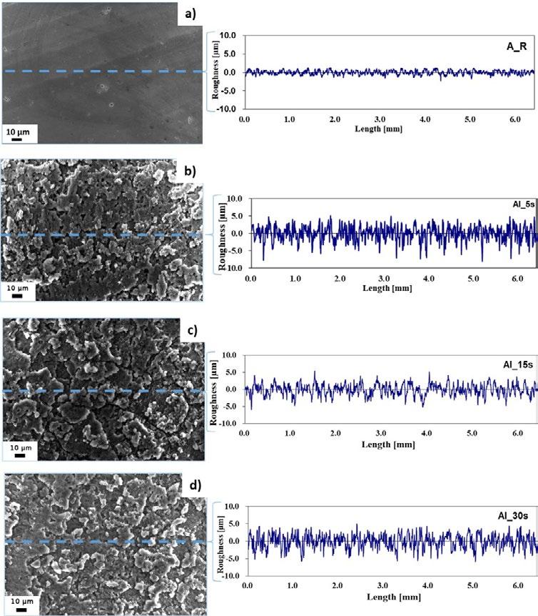
Fig. 1 illustrates the SEM images and the roughness profiles of the AA 6082 surfaces at different etching times. It can be seen that the treatment of the AA 6082 substrates with HF/HCl etchant for different of times influence the surface morphology of the as-received aluminium substrates from a flat toward a hierarchical rough surface. After 5 seconds of etching, micrometer-sized rough structure was formed like a coral network. At increasing etching time to 15s, the coral network microstructure is still preserved and becomes more homogeneous and regular with quite similar sequence of peaks and valleys as shown in the sur-
face profile (Fig.1.c). Then, at longer etching time (30s), the aluminium surface appears rough but begins to slightly lose the sequence order of peaks and valleys (Fig. 1.d).
These microstructures are a consequence of the intrinsic substrate heterogeneity. Indeed, the aluminium alloy has a large number of dislocations, defects and microstructural heterogeneities. These local defects are more reactive than other substrate areas in this acidic etchant [12]. Meanwhile, the impurities in the neighbourhood of these defects could also magnify the chemical etching re-
action. The dissolution phenomena in the aluminium induced by hydrofluoric acid usually starts after a relatively high immersion time (30–50 min) [12]. The addition of a small quantity of hydrofluoric acid to other acids allows the electrochemical dissolution of the alloy to be promoted. In addition, HF acid reacts with Si-rich precipitates, favouring a selective dissolution in its neighbouring area,
thus influencing the large corrosion phenomena induced by HCl acid solution. The selective dissolution favoured by HF, coupled with the wide and general action of HCl, could be considered responsible for the obtained coral-like structure.
Fig.2 - Skewness parameters, Contact angle (CA) and sliding angle (SA) of etched samples.

In order to quantify the differences between the three etched surfaces and assess their relationship with the wettability behaviour of the aluminium alloy surfaces, the roughness parameters were calculated for Al surfaces after treatment.
An important parameter, Skewness (Ssk), was selected to evaluate the effect of the etching time on the surface morphologies. The skewness parameter, Ssk, is related to the degree of the symmetry of the variation in a profile about its mean line. Ssk near zero, if the distribution is quite symmetrical (equal reparation between peaks as valleys). A low negative Ssk value indicates that the height distribution is skewed above the mean plane and it is related to a profile with deep valleys such as porous structure.
In fact, the histogram of S Sk against the etching time evidenced a dependence between these parameters. Indeed, the sample etched for 15 seconds is characterized by the closest Ssk to zero indicating a quite symmetric distribution of peaks and valleys. However, at the lowest immersion time (5s), the etched surface is characterized by the lowest SSk parameter indicating the presence of deep valleys. At the highest etching time (30s), a decrease of skewness value of about 12% was observed demonstrating that
the distribution of peaks and valleys on this surface are less homogenous than the sample etched for 15s. In order to study the effect of the achieved morphologies on the wetting behaviour of the aluminium alloy samples, the water contact angles and the water sliding angles were measured (Fig. 2).
It is clear that superhydrophobicity was initially enhanced by increasing the etching time, and then reduced after an etching time of 30s. In particular, the highest CA (180°) and the lowest SA angles (0°) were obtained for the surface etched for 15s. Indeed, the CA rises by about 12%, from 161° to around 180°, and the SA decreases from 27° to around 0° degrees when the etching time increases from 5s to 15s min. While all the aluminium specimens are superhydrophobic with a CA higher than 150 °, the difference in the wetting behaviour at increasing etching time is related to the diverse interactions of the as prepared surface with water (Cassie-Baxter or Wenzel states).
In the Cassie-Baxter, the air-layer entrapped by the rough structure is able to significantly reduce the contact angle between the liquid and the surface, and thus the water droplet easily rolls off as on the case of the sample 15s. However, in the Wenzel state, the liquid droplet pene-
trates the surface grooves resulting in high adhesion and thus high sliding angle. Consequently, the portion of air trapped in the solid/water interface is the key factor that controls the CA and SA and thus the anti-wetting surface type.
Our results point out that a transition between Wenzel and Cassie-Baxter states can be controlled by modifying the etching time. The 5s sample is in intermediate state between Wenzel and Cassie-Baxter since the sliding angle is quite elevated (27°) indicating that the air layer is not continuous (air is only partially entrapped into the surface valleys). However, the 15s and 30s samples are Cassie-Baxter surfaces as indirectly identifiable by the low SA (0≤SA≤10°) which is probably due to the regular and homogeneous roughness that enhance the formation of an almost continuous air film (Fig.2). This result is consistent with the literature. In fact, Li and Amirfazli demonstrated that the achievement of a high CA and a low SA
on a solid surface requires a hierarchical structure with a high air fraction [13]. When the etching time increases to 30s, the ordered structure starts to be lost which affect the air layer. Indeed, the air fraction trapped on the solid surface of the 30s sample surface is probably lower than the 15s sample resulting in lower CA (174°) and higher SA (10°) but it still enough to maintain the Cassie-Baxter state (Fig.2). Thus, the water repellence behaviour follows the same order of the Skewness parameter: The best behaviour was observed on the 15s sample surface having the highest SSK followed by the 30s and then the 5s samples. Superhydrophobic surfaces with different water repellency behaviour were successfully elaborated. This reduction in the wettability of these surfaces may deeply affect their corrosion resistance.
Fig.3 - EIS curves of as received aluminium alloy and the superhydrophobic surfaces in seawater at room temperature.
The ability of the superhydrophobic surfaces to protect the aluminium alloy from corrosion was evaluated by the electrochemical impedance spectroscopy (EIS). The EIS curves recorded for the as received aluminium alloy and superhydrophobic aluminium surfaces, having different CA and SA, in simulated seawater (3.5 wt% NaCl solution)
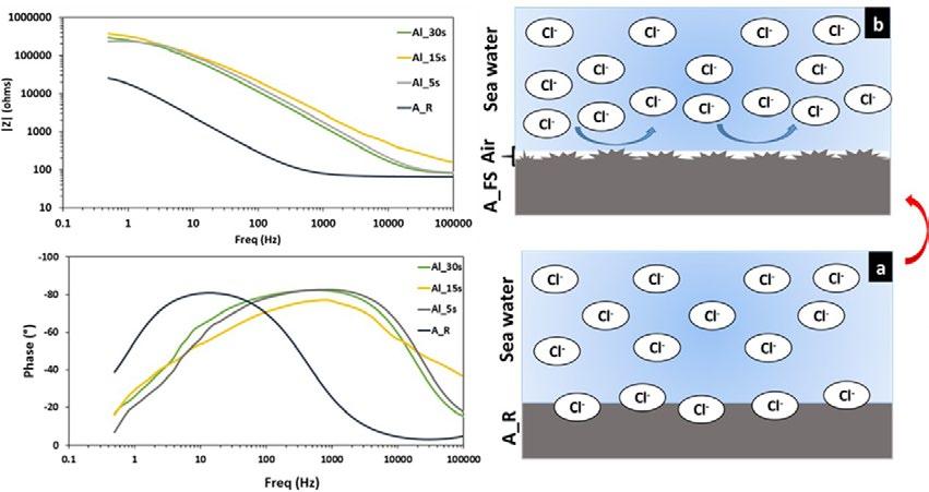
are presented in Fig.3.
At low frequencies, all impedance modulus curves exhibit a small plateau. The plateau in the as received sample spectrum is ascribed to the thin aluminium oxide surface (~2.5*104 Ω *cm2 at 0.5 Hz). After the creation of superhydrophobic surfaces, an evident increase of impedance
magnitude in all the frequency range can be highlighted. Indeed, an increase of the |Z| by more than one order of magnitude compared to the A_R sample was observed. The highest magnitude of impedance modulus, about ~3*105 Ω *cm2 at low frequency range, was observed for Al_15s which has the highest CA and the lowest SA.
By evaluating the phase plot, it is possible to identify apparently a single time constant for all batches. The as received sample, A_R, exhibits a peak in the phase angle at low frequency (~101 Hz) that can be associated to the aluminium oxide layer. The EIS spectra of superhydrophobic samples are characterized by a wider phase peak at high frequencies. In fact, a time constant can be identified at high frequency (~103 Hz), in correspondence of the phase peak. This trend is typical of the capacitive behaviour of external protective layers. In addition, the phase angle near to -90° indicates that this protective film provides a good barrier action. This behaviour can be ascribed to the coupled action of the surface texturing and silanization. The surface modification acts on shift of the peak at very high frequency, probably related to the formation of a protective layer of air. This air layer can work as the dielectric for a parallel plate capacitor that prevents the Cl- from moving between the electrolyte and the aluminium surface. Indeed, the trapped air on the hierarchical rough surfaces of the superhydrophobic aluminium surfaces acts as an “air cushion” inhibiting the penetration of corrosive ions (Cl-) and leading to an improved corrosion protection as shown in the Fig.3.b. Thus, these superhydrophobic surfaces enhances the corrosion resistance of the aluminum alloy.
CONCLUSIONS
Superhydrophobic surfaces were created on aluminium alloy by the coupling the chemical etching and the decrease of surface energy obtained by silane coating. The wettability state of these superhydrophobic surfaces varies with the etching time. In fact, the Cassie-Baxter state (CA ≈180° and SA ≈ 0°) was achieved by a chemical etching for 15s. On the other hand, an intermediate sate between Wenzel and Cassie-Baxter was obtained for the lowest etching time 5s. Thus, the wetting transitions from Wenzel to Cassie-Baxter can be controlled by modifying the etching time. The wetting state alteration is based on the distribution of the roughness peaks and valley. In addition, the as-modified aluminium surfaces revealed a good corrosion resistance behaviour in 3.5 wt% NaCl solution compared with the as received one and the best results were obtained on the Cassie-Baxter surfaces. Thus, a symmetric distribution of peaks and valleys is the key factor for obtaining the Cassie-Baxter state and thus for improving the superhydrophobicity and the corrosion behaviour of the aluminium alloy.
REFERENCES
[1] L. Calabrese, E. Proverbio, A. Khaskhoussi, Superhydrophobic behaviour of modified AA6082 alloy surfaces, Metall. Ital. 111 (2019) 6–10.
[2] A. Khaskhoussi, L. Calabrese, E. Proverbio, An Easy Approach for Obtaining Superhydrophobic Surfaces and their Applications, Key Eng. Mater. 813 (2019) 37–42. https://doi.org/10.4028/www.scientific.net/KEM.813.37
[3] B. Zhang, Q. Zhu, Y. Li, B. Hou, Facile fluorine-free one step fabrication of superhydrophobic aluminum surface towards self-cleaning and marine anticorrosion, Chem. Eng. J. 352 (2018) 625–633. https://doi.org/10.1016/j.cej.2018.07.074.
[4] X. Wang, Y. Pan, X. Liu, H. Liu, N. Li, C. Liu, D.W. Schubert, C. Shen, Facile Fabrication of Superhydrophobic and Eco-Friendly Poly(lactic acid) Foam for Oil-Water Separation via Skin Peeling, ACS Appl. Mater. Interfaces. 11 (2019) 14362–14367. https://doi. org/10.1021/acsami.9b02285.
[5] W. Li, Y. Zhan, S. Yu, Applications of superhydrophobic coatings in anti-icing: Theory, mechanisms, impact factors, challenges and perspectives, Prog. Org. Coatings. 152 (2021) 106117. https://doi.org/10.1016/J.PORGCOAT.2020.106117
[6] K. Vidal, E. Gómez, A.M. Goitandia, A. Angulo-Ibáñez, E. Aranzabe, The Synthesis of a Superhydrophobic and Thermal Stable Silica Coating via Sol-Gel Process, Coatings 2019, Vol. 9, Page 627. 9 (2019) 627. https://doi.org/10.3390/COATINGS9100627.
[7] Q. Fan, X. Ji, Q. Lan, H. Zhang, Q. Li, S. Zhang, B. Yang, An anti-icing copper-based superhydrophobic layer prepared by one-step electrodeposition in both cathode and anode, Colloids Surfaces A Physicochem. Eng. Asp. 637 (2022). https://doi.org/10.1016/J. COLSURFA.2021.128220.
[8] R. Tan, H. Xie, J. She, J. Liang, H. He, J. Li, Z. Fan, B. Liu, A new approach to fabricate superhydrophobic and antibacterial low density isotropic pyrocarbon by using catalyst free chemical vapor deposition, Carbon N. Y. 145 (2019) 359–366. https://doi.org/10.1016/J. CARBON.2019.01.041
[9] X. Su, H. Li, X. Lai, Z. Yang, Z. Chen, W. Wu, X. Zeng, Vacuum-assisted layer-by-layer superhydrophobic carbon nanotube films with electrothermal and photothermal effects for deicing and controllable manipulation, J. Mater. Chem. A. 6 (2018) 16910–16919. https:// doi.org/10.1039/C8TA05273E
[10] P.D. Srivyas, M.S. Charoo, Application of Hybrid Aluminum Matrix Composite in Automotive Industry, Mater. Today Proc. 18 (2019) 3189–3200. https://doi.org/10.1016/J.MATPR.2019.07.195.
[11] A. KHASKHOUSSI, L. CALABRESE, E. PROVERBIO, Effect of the Cassie Baxter-Wenzel behaviour transitions on the corrosion performances of AA6082 superhydrophobic surfaces, Metall. Ital. (2021) 15–21.
[12] M.E. Straumanis, Y.N. Wang, The Rate and Mechanism of Dissolution of Purest Aluminum in Hydrofluoric Acid, J. Electrochem. Soc. 102 (1955) 370–381. https://doi.org/10.1149/1.2430103.
[13] W. Li, A. Amirfazli, Microtextured superhydrophobic surfaces: A thermodynamic analysis, Adv. Colloid Interface Sci. 132 (2007) 51–68. https://doi.org/10.1016/j.cis.2007.01.001
Fabbricazione di superfici superidrofobiche su lega di alluminio AA6082 mediante etching in soluzione HF/HCl per una maggiore protezione dalla corrosione
La sfida più importante nella cantieristica navale è la riduzione del peso delle strutture navali tradizionalmente realizzate in acciaio al fine di aumentarne la stabilità e la sicurezza. L'alluminio e le sue leghe sono potenziali materiali candidati grazie alla loro leggerezza e all'eccellente saldabilità. Tuttavia, le leghe di alluminio sono soggette a corrosione per vaiolatura in ambiente salino. Il controllo dell'idrorepellenza della superficie dell'alluminio può fornire una soluzione efficace per la protezione della stessa. Nel presente lavoro sono stati valutati l'effetto dell'etching chimico sulla morfologia della superficie e il comportamento dopo idrofobizzazione con un trattamento in soluzione base silanica. Sono stati considerati tempi di attacco diversi per ottimizzare l'effetto del trattamento. I risultati indicano che le superfici preparate hanno raggiunto il valore soglia di superidrofobicità (150°). Tuttavia, gli angoli di contatto e di scorrimento dipendono fortemente dal tempo di attacco. Le superfici superidrofobiche ottimizzate hanno mostrato una maggiore protezione dalla corrosione rispetto all'AA6082 tal quale in acqua di mare simulata.
Microstructural and electrochemical characterization of dissimilar joints of aluminum alloy AW5083 and carbon steel S355 obtained by friction welding
A. Khaskhoussi, G. Di Bella, C. Borsellino, L. Calabrese, E. ProverbioOver the past twenty years, friction-welding technology, in particular the Friction Stir Welding (FSW) has become a potential industrial welding method that has been used efficiently for combining similar and dissimilar materials. The latter solution is very interesting in ship-building, where the use of aluminum in the superstructures allows lowering of the center of gravity for a better stability of the ship. In making dissimilar joints, the FSW technique is more cost and time efficient, allows to weld various sheet thickness with different joint configurations. In this work a coupled mechanical, metallurgical and electrochemical characterizations of dissimilar joints of aluminum alloy AW5083 and carbon steel S355 obtained by butt joint welding (FSW) were performed. The results showed that during the FSW process several well-defined microstructural zones are generated, that affected the mechanical performances and the corrosion behavior of the weld.
INTRODUCTION
Research on joining of steel to aluminum alloys is of great importance due to the rising demand for lightweight construction in several industries especially the marine one [1]. However, the main obstacles to attaining effective dissimilar joining of steel and aluminum are the wide differences in their mechanical, chemical and physical properties. In addition, the high heat input of fusion welding processes induces the formation of brittle and thick intermetallic compounds (IMCs) causing the reduction of the performances of the produced joints [2]. Thus, a lower heat input is essential for fabricating a high-quality joint between steel and aluminum. One of the promising and new solid-state welding techniques for joining of different metals and alloys is friction stir welding (FSW). FSW has several advantages over more standard techniques, such as the short welding time, low heat input, and superior mechanical properties of the weld [3]. Furthermore, due to its working principle, FSW allows for welding with few to no imperfections common in fusion welding, such as lack of fusion, cracking, war-
Department
akhaskhoussi@unime.it, lcalabrese@unime.it , eproverbio@unime.it
ping porosity, distortion, loss of alloying elements, and formation of oxide due to the lower heat inputs [4]. Despite the numerous studies devoted to the production of aluminum/steel joints by FSW, much less attention has been paid to their electrochemical behavior. In this study, we evaluate the relationships between the metallographic structure, the mechanical behavior and the electrochemical performances of aluminum alloy AW5083/S355 steel joint obtained by FSW using different techniques: microhardness indentation, Scanning electron microscopy (SEM), energy dispersive X-ray spectroscopy (EDS) and electrochemical tests.
MATERIALS AND METHODS
Five mm thick S355 steel sheet was joined by Friction Stir Welding (FSW) with the aluminum alloy EN AW-5083 H111 (5 mm thick) in the butt weld configuration provided by the company RIFTEC (Geesthacht, Germania). Friction stir welding was done with welding speed of 300 mm/min at 400 rpm using force control at 30kN. Then, the samples were cut transversally (cross section), grinded, polished, and etched with nital (2%) for 20 seconds at room temperature. At the end, the specimens were rinsed with cold bidistilled water and ethanol and dried with
RESULT AND DISCUSSION
warm air. Microhardness was measured on cross-sections extracted from the middle of the welds, a region that is representative of the stable length of each weld. The vickers hardness measurements were carried out using FUTURE-TECH FM-300e with a load of 500g. As indicating in the ASTM E384-17 standard (Standard Test Method for Microindentation Hardness of Material), a minimum spacing distance between two indentations of 2.5 times the value of indent diagonal was respected. The weld zones and other microstructural features were also investigated by optical microscopy, following standard metallographic preparation. Morphological analysis was performed by scanning electron microscopy (SEM-FIB Zeiss Cross Beam 540). Furthermore, the composition of the different areas was determined by energy dispersive spectroscopy (EDS) (Aztec Oxford). Minicell techniques (about 0.785 mm2) was adapted for electrochemical characterization. A Tensiometer was used to control the flow of the fresh solution over the selected working electrode area. The Al-Steel interface was analyzed by means of Scanning Kelvin Probe (SKP) test was performed using BioLogic electrochemical workstation. The step scan mode was applied with a step size of 20 µm using kelvin probe having a tip size of 0.5 mm.
-
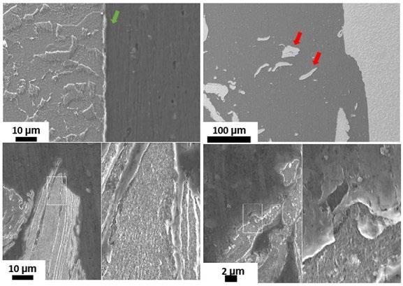
Cross section of weld was observed by scanning electron microscope (SEM), at the aluminum and steel interface and the different micrographs are reported in Fig.1. The formation of a thin intermetallic compound (IMC) layer (showed by the green arrow) at aluminum and steel interface caused by the frictional heating on the surface under the action of the rotating shoulder, can be noticed [1]. Some fragments scattering in the Al matrix were also formed (red arrows).
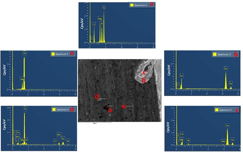
The Energy Dispersive Spectroscopy (EDS) analyses were conducted to identify fragments composition and characterize the weld interface. The results were summarized in Fig. 2. The EDS analysis finds the presence of Al, Mg, Si in the selected zone “a”. The EDS analysis in the point “b” confirms that the fragments present in the Al matrix are formed principally by Fe. This phenomenon is probably due to the stirring effect of the pin, which pulled small bits of steel from the surface and scattered them in the aluminum [2]. Indeed, the steel fragments that were sheared off from the surface of the steel edge were scattered in the Al matrix because of the tool movement in the feed path. As well, there is no clear presence of stirred aluminum or particles in steel nugget due to the difficulty of insertion the soft metal (Al) in hard metal (Steel), and the steel did not reach the degree of plasticity to make it easy for intercalation.
The EDS analysis was performed also in the weld interface (point “c”) to examine whether intermetallic compounds were formed in the steel and the aluminum alloy interface. The results suggest that an intermetallic compounds were formed and composed of Al, Fe and Mn [2,3]. According to Elnabi at al. the steel fragments can also react with the aluminum matrix and formed brittle IMCs. Indeed, the larger steel fragments react with Al to make a thick IMC layer around the fragment. The core of the particle influences by dynamic recrystallization that makes it more fine grains. Whereas the smaller particles transfer to a complete IMC particle [3]. The EDS of the point “d” shows a phase rich in Al, Mg, Si, Mn, Cr and Fe. Similar spherical precipitates believed to consist primarily of Mg and Al were reported in the study of the Al 5083 microstructure [4]. The point “e” indicated the presence of aluminum-magnesium intermetallic precipitates or inclusions in the aluminum microstructure [5]. To understand the effect of these microstructure features on the mechanical properties of the welding a detailed study of the hardness profile and its relationship with the microstructure was conducted and discussed in the next section.
The results of the Vickers indentation, realized using the microhardness across the thickness section of dissimilar weldments versus the distance are plotted in Fig.3 to evaluate the variation of the micro-hardness across the joint.
The profile exhibits a non-symmetrical trend due to the different physical and mechanical properties of dissimilar base materials. The hardness profile confirms also the existence of interfacial area between the aluminum alloy and the steel sides in the stirred zone (indicated as SZ in the figure). Indeed, four zones can be distinguished after the FSW process: Base metal, the stir zone, thermo-mechanical affected zone (TMAZ) and the heat-affected zone (HAZ). According to the present results, the hardness values on the aluminum side were almost constant in all directions because the aluminum base metal is a non-heat-treatable, work-hardened aluminum alloy [6]. Thus, no significant FSW effect on the hardness of the aluminum
HAZ and the THAZ zones. The average hardness aluminum zone (base metal) is around 55 HV, while it is 158 HV in the base steel. The highest values of hardness was observed on steel THAZ. The maximum reached value of hardness in this zone is about 212 HV. Then the hardness gradually decreases in the direction of the HAZ, but it is still higher than the base steel. Thus, the narrow HAZ and TMAZ formed in the steel region, due to rapid cooling from the estimated peak temperature down to atmosphere, have higher hardness then the base metal. To understand this difference in the hardness behavior of the different welding zones, the microstructures of the different regions were evaluated.
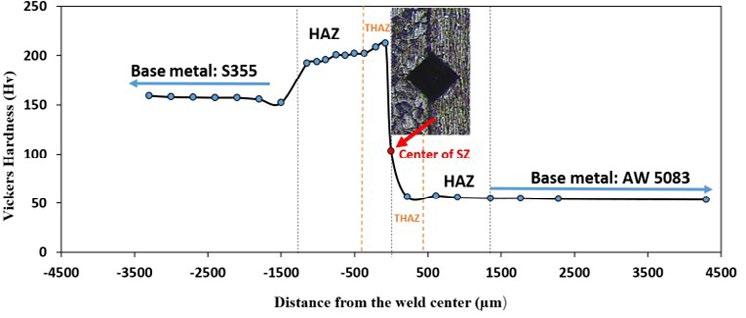
Optical images showing the microstructure of different regions are illustrate in Fig.3.b.The grain structure of all areas has the possibility of deformation during the FSW process. According to these presented results, the grain structure in HAZ, TMAZ and especially in the SZ region is largely refined which explains the difference in hardness values. The SZ, TMAZ and HAZ have a smaller grain size than the steel base metal due to the recrystallization of these grains when heated by the tool stirring action. In addition, the TMAZ and HAZ are formed due to the recrystallization of steel grains. In fact, the main controlling mechanisms for such grain structural modification are based on the operative dynamic restoration phenomena
during the FSW process. The involved mechanisms mostly include dynamic recovery (DRV), continuous dynamic recrystallization (CDRX), discontinuous dynamic recrystallization (DDRX), and geometric dynamic recrystallization (GDRX) depending on the stacking fault energy of the examined metals and alloys. Indeed, grains can nucleate during severe plastic deformation of friction-stirring process, and in following cooling from the peak temperature after the FSW process will render the grain growth, and the rate of grain boundaries migration lead to the formation of a fine grain structure in steel side of dissimilar weld [7].

Fig.4 - SKP measurement of AW 5083 Aluminum/ S355 Steel dissimilar joint.
The SKP and Polarization tests are reported in Fig. 4. It is observed that there is a considerable difference in the surface potential between the intermediate zone (HAZ+SZ+THAZ) (green) and the two base metals. This intermediate zone has a surface potential less than the aluminum alloy (blue) and higher than the steel zone (red), confirming that the
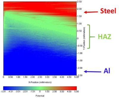
aluminum region is anodic whereas the steel zone is more cathodic in nature. Although, there is a gradual decrease of potential from aluminum to steel going through the intermediate zone indicating that this zone has an intermediate corrosion behavior.
Fig.5 - Microcell polarization tests of AW 5083 Aluminum/S355 Steel dissimilar joint.
The Electrochemical tests performed on the AW 5083 Aluminum and the S355 steel give an insight into various details of their corrosion behavior such as the corrosion kinetics, passivity and the electrochemical behavior of the alloys among other things. The electrochemical behavior of the alloys depends on several factors such as the intermetallic particles and phases and even the production methods of the alloy. All potentiodynamic polarization measurements were started 5 minutes after the surface contact with the minicell (Fig. 5). The aluminum base material exhibits, Ecorr
of around -810 mV and a pitting potential of around -731 mV. The corrosion current density (Icorr) measured for the aluminum alloy is below 10-4 mA/mm-2. At the pitting potential, the current density increases immediately up to value six times higher than Ecorr. The free corrosion potential of the steel shows a value of about -630 mV. However, the heat-affected zone of the steel shows a slightly higher corrosion potential and lower corrosion current than the base metal demonstrating that the heat effect slightly decreases the corrosion rate, which is probably related to the hard-
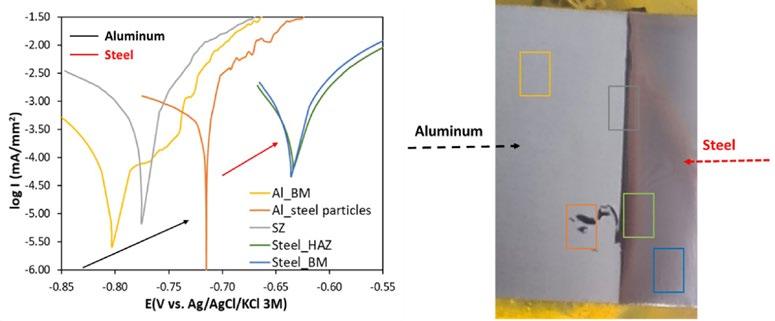
ness increase. The interface zone showed an intermediate corrosion potential of about -710 mV indicating that the thin intermetallic layer formed during the FSW process did not affect negatively the corrosion resistance of the joint unlike in the case of fusion welding [8].
CONCLUSIONS
In the present study, a dissimilar joints of aluminum alloy AW5083 and carbon steel S355 obtained by friction welding were characterized and the relationship between their microstructural features and their electrochemical behavior were discussed. The results showed that:
• The SZ, TMAZ and HAZ have a smaller grain size than the steel base metal due to the recrystallization of these
grains by the tool stirring action.
• The maximum value of hardness of about 212 HV was reached in the HAZ, whereas the value was 55 HV in the aluminium and 158 HV in the steel.
• The zones formed during the FSW such as the stir and the heat affected zones did not affect negatively the corrosion resistance of the joint.
ACKNOWLEDGMENT
The authors acknowledge the SIMARE funding under the reference “Code 08ME7219090182 - CUP G48I18001090007, University of Messina”
REFERENCES
[1] T. Tanaka, M. Nezu, S. Uchida, T. Hirata, Mechanism of intermetallic compound formation during the dissimilar friction stir welding of aluminum and steel, J. Mater. Sci. 55 (2020) 3064–3072. https://doi.org/10.1007/s10853-019-04106-2.
[2] K. Martinsen, S.J. Hu, B.E. Carlson, Joining of dissimilar materials, CIRP Ann. 64 (2015) 679–699. https://doi.org/10.1016/J. CIRP.2015.05.006.
[3] R. Hatano, T. Ogura, T. Matsuda, T. Sano, A. Hirose, Relationship between intermetallic compound layer thickness with deviation and interfacial strength for dissimilar joints of aluminum alloy and stainless steel, Mater. Sci. Eng. A. 735 (2018) 361–366. https://doi. org/10.1016/J.MSEA.2018.08.065.
[4] N.R. Ramesh, V.S.S. Kumar, Experimental erosion-corrosion analysis of friction stir welding of AA 5083 and AA 6061 for sub-sea applications., Appl. Ocean Res. 98 (2020) 102121. https://doi.org/10.1016/J.APOR.2020.102121.
[5] G. Lucadamo, N.Y.C. Yang, C.S. Marchi, E.J. Lavernia, Microstructure characterization in cryomilled Al 5083, Mater. Sci. Eng. A. 430 (2006) 230–241. https://doi.org/10.1016/J.MSEA.2006.05.039.
[6] A. Elrefaey, M. Gouda, M. Takahashi, K. Ikeuchi, Characterization of aluminum/steel lap joint by friction stir welding, J. Mater. Eng. Perform. 14 (2005) 10–17. https://doi.org/10.1361/10599490522310.
[7] T.R. McNelley, S. Swaminathan, J.Q. Su, Recrystallization mechanisms during friction stir welding/processing of aluminum alloys, Scr. Mater. 58 (2008) 349–354. https://doi.org/10.1016/J.SCRIPTAMAT.2007.09.064.
[8] A. Canakcı, S. Ozkaya, F. Erdemir, A.H. Karabacak, M. Celebi, Effects of Fe–Al intermetallic compounds on the wear and corrosion performances of AA2024/316L SS metal/metal composites., J. Alloys Compd. 845 (2020) 156236. https://doi.org/10.1016/J. JALLCOM.2020.156236.
Caratterizzazione microstrutturale ed elettrochimica di giunti dissimili di lega di alluminio AW5083 e acciaio al carbonio S355 ottenuti mediante saldatura ad attrito
Negli ultimi venti anni, la tecnologia della saldatura ad attrito, Friction Stir Welding (FSW), è diventata un potenziale metodo di giunzione industriale che è stato utilizzato in modo efficiente per la giunzione di materiali simili e dissimili. Quest’ultima soluzione risulta essere molto interessante in campo navale, dove l'utilizzo dell'alluminio nelle sovrastrutture permette l'abbassamento del baricentro per una migliore stabilità della nave. Nella realizzazione di giunti dissimili, la tecnica della FSW è più efficiente in termini di costi e tempi, permettre di saldare efficacemente vari spessori di lamiera con diverse configurazioni di giunti. In questo lavoro è stata eseguita una caratterizzazione meccanica, metallurgica ed elettrochimica accoppiata di giunti dissimili di lega di alluminio AW5083 e acciaio al carbonio S355 ottenuti mediante saldatura ad attrito (FSW) di testa. I risultati hanno evidenziato che durante il processo FSW si generano diverse zone microstrutturali ben definite, che influiscono sulle prestazioni meccaniche e il comportamento alla corrosione della saldatura.
Effect of macro- and microstructural features on the corrosion behavior of additively manufactured alloy 625
F. Carugo, M. Cabrini, A. Carrozza, S. Lorenzi, T. Pastore, G. Barbieri, F. Cognini, M. MoncadaThe aim of the work is to investigate the general and localized corrosion behavior of Alloy 625 obtained via different AM technologies, namely laser powder bed fusion (LPBF) and metal fused filament fabrication (MFFF). The outcomes of these evaluations were compared with the traditionally manufactured material (hot rolling). The macro- and microstructures as well as unique surface features of the AM-produced spec-imens were assessed in terms of digital optical microscopy and scanning electron microscopy. Intergranu-lar corrosion susceptibility tests, in compliance with ASTM G28 method A (1), potentiodynamic and poten-tiostatic polarization tests were performed. The electrochemical tests were carried out in sulfuric acid ac-cording to the ASTM G5 standard (2) and in deaerated chloride solutions. The results demonstrated that the surface features, porosity, as well as the microstructure are strictly dependent upon the manufacturing technology. Corrosion morphologies change significantly in function of the unique macro- and microstruc-tural features. Susceptibility to intergranular corrosion tests carried out on the MFFF alloy only revealed not penetrating attack. The results of potentiostatic and potentiodynamic tests showed a passive behavior over a wide range of potentials, thus confirming the very high corrosion resistance to localized corrosion of the additive manufacturing Alloy 625 in neutral chloride solutions. In acidified chloride solution (pH = 3) the presence of crevice attacks on MFFF specimens was detected.
INTRODUCTION
Additive manufacturing (AM) technologies are redefining traditional design and manufacturing strategies, thus granting the possibility to obtain materials and products with high-added value and outstanding performances. These techniques rely on a layer-by-layer approach to generate unique microstructures. Significant efforts have been mainly made by researchers and industry to optimize process parameters and post-processing heat treatments to achieve high mechanical performances. However, also corrosion resistance is fundamental for the alloys adopted in severe operating environments. For these applications, nickel-based Alloy 625 is commonly used owing to its good tensile strength and resistance against chloride-ion stress corrosion cracking and localized corrosion in marine, Oil & Gas industry, and chemical processing environments (3–6).
Marina Cabrini, Francesco Carugo, Alessandro Carrozza, Sergio Lorenzi, Tommaso Pastore
Università di Bergamo Giuseppe Barbieri, Francesco Cognini, Massimo Moncada ENEA
Among the AM techniques available, the most widespread are the powder bed-based processes, such as Laser Powder Bed Fusion (LPBF) (7). However, recent techniques combining printing with debinding and sin-tering processes are gaining popularity. Metal Fused Filament Fabrication (MFFF) is an emerging multi-step additive manufacturing process that uses a metal–polymer filament as a feedstock. The paper is devoted to the study of the influence on the corrosion behavior of Alloy 625 of LPBF and MFFF AM-technologies. The outcomes of these evaluations were compared with data published in previous paper (8,9).
MATERIALS AND METHODS
The MFFF-manufactured specimens were built by using a
commercial metal powder-polymer filament Mark-forged Inconel 625 that meet chemical requirements of ASTM B443 standard(10), after printing, washing, and sintering (11). An EOS gas atomized powder was used for LPBF specimens. The distribution of the powders size is within the range with a d10 of 16 μ m and d90 of 48 μ m. For comparison purpose, a 16 mm diameter hot worked (HW) bar was considered. The bar was supplied in the annealed condition, after a heat treatment at 980 °C for 32 min, followed by water quenching (Grade 1, according to ASTM B446 (12)). The chemical com-positions are reported in Tab. 1.
Tab.1 - Chemical compositions.
Chemical composition of Alloy 625 LPBF powder, composition limits according to ASTM B443 (10) and annealed bar (%wt.)
Element LPBF powder ASTM B443 (10) HW
C 0.013 0.1 max 0.036 Si 0.1 0.5 max 0.25 Mn 0.03 0.5 max 0.19 P <0.001 0.015 max 0.007 S 0.002 0.015 max 0.001
Cr 22.8 20.0 – 23.0 21.6 Mo 8.1 8.0 – 10.0 8.26 Ni 64.37 (Balanced) bal 61.9 Nb 3.66 3.15 – 4.15 3.66 Ti 0.17 0.4 max 0.24 Al <0.01 0.4 max 0.2 Co 0.17 1.0 max 0.02 Ta 0.13 - 0.01 Fe 0.43 5.0 max 3.1 Nb+Ta 3.79 - 3.67
Specimens
The LPBF specimens were manufactured by using an EOSINT M270 Dual Mode machine, operating in an argon atmosphere. The process parameters and scanning strategy
were optimized in order to produce parts with very low porosity, as reported in a previously published work (13). MFFF specimens were obtained by using the Metal X System (Markforged). The manufacturing operation consisted
of three main steps: printing a green part of metal powder bound in a polymer matrix, debinding and then sintering to obtain a dense part. The single layer deposition strategy involved the deposition of 4 contouring layers (wall layers) and the filling of the internal section (infill).
Two types of specimens were adopted. Cubic specimens were used for microstructural analysis and immersion test – 15 mm and 16 mm side for LPBF and MFFF processes respectively. Disks height 5 mm were employed for potentiodynamic and potentiostatic polarization tests with 15 mm and 16 mm diameter (for LPBF and MFFF, respectively). 5 mm-tall cylindrical specimens were obtained by cutting the hot-worked bar.
Corrosion tests
Susceptibility to intergranular corrosion tests were performed on the cubic specimens. Boiling ferric sul-fate/ sulfuric acid test were carried out according to ASTM G28 standard, method A (1). Before testing, the surfaces of specimens were ground by silicon carbides emery paper up to 1200 grit. Two faces were ground and polished up to 1 μ m, using a diamond paste, to allow the observation of corrosion attack mor-phologies on the main planes (parallel and perpendicular to the building direction). Afterwards, the speci-mens were rinsed in water, degreased in an acetone ultrasonic bath and dried before the immersion in the boiling test solution. Before and after tests, the samples were weighed by means of analytic scale to measure the weight loss and corrosion rate. Finally, the specimen was observed using a scanning electron microscope (SEM) in order to investigate the corrosion morphology.
Potentiodynamic and potentiostatic tests were performed on disk specimens. The testing surfaces were firstly ground using SiC emery papers and subsequently polished up to 1 μ m diamond paste. Before the tests, all the specimens were ultrasonically cleaned in acetone at room temperature, dried and allowed to passivate in air at room temperature for 1 hour. The tests were performed in a 1-liter standard three elec-trode cell (ASTM G5 (2)) using a PTFE sample holder with a circular exposed area of 10 mm diameter, a Saturated Calomel Electrode (SCE) and two graphite counter electrodes. The testing solution was de-oxygenated by means of nitrogen gas purging, maintained throughout the whole test. A thermostatic water bath provided constant
temperatures. The potentiodynamic tests were conducted in three testing solutions:
• 1 N H2SO4 solution – according to ASTM G5 (2) at 30°C
• 0.6 M NaCl + HCl, pH 3 at 40°C
• 0.6 M NaCl, pH 7 at 40°C
Before the cyclic potentiodynamic tests, the open circuit potential (OCP) was monitored until stability was achieved. The tests were carried out according to ASTM G5 (2) using a 10 mV/min scan rate. The polariza-tion tests in chloride solution were conducted from 10 mV below the OCP up to 1 V vs. SCE or until the an-odic current density reached 10 mA/cm2. Afterwards, a reverse scan returned the potential to the initial OCP value.
Potentiostatic tests were carried out in NaCl at pH 7 at +200 mV or +500 mV vs. SCE and in acidified chlo-ride solution at +200 mV vs. SCE for 24 hours, with an acquisition rate of 1 Hz. Before the test, the OCP was monitored for 1 hour.
RESULTS AND DISCUSSION
Fig. 1 shows the micrographs of the MFFF-manufactured specimens realized on the two main planes, i.e., perpendicular (Fig. 1a) and parallel (Fig. 1b) to the building direction. In both cases, there is a continuous pattern of defects due to an incomplete densification of the green part during the sintering process. Particu-larly larger porosities are observed in the external part, in correspondence with the wall layers. This leads to very different porosity values between the external zone (wall layers) and the internal one (infill layers) as shown in Fig. 1c. Through digital image analysis, a porosity value of about 7.7% in the external region was obtained, while in the internal part this value was about 1.1%.
(a) (b) (c)
Fig.1 - Micrograph of MFFF-manufactured samples: a) perpendicular direction b) parallel direction c) particular of the parallel direction in correspondence with the wall layers
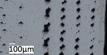
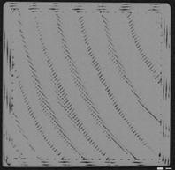
Fig. 2 shows the microstructure obtained after chemical etching. The microstructure of MFFF-processed specimens comprises equiaxed austenite grains, coarser than in the HW condition. This is also completely different from
the microstructure observed on the LPBF-manufactured specimens (9), confirming that the microstructure is strictly dependent upon the manufacturing technique adopted.
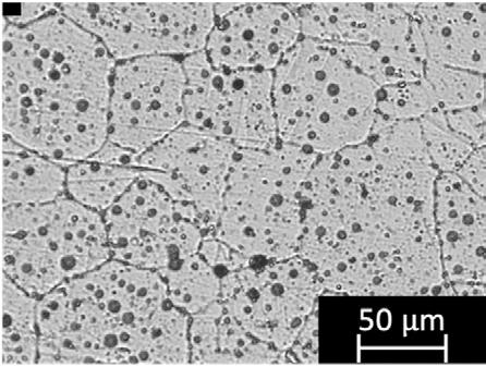
Fig.2 - Representative micrograph of a MFFF-manufactured sample.
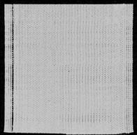
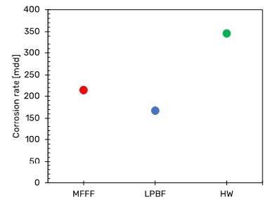
Fig. 3 shows the results of the susceptibility to intergranular corrosion test carried out on a MFFF-built specimen in terms of corrosion rate. The results obtained on LPBF and HW specimens and already published in previous work were considered as a comparison (9).
The corrosion rate of the specimens obtained by means MFFF is higher than those obtained for LPBF, but it is still lower than that one obtained on HW specimens.
Fig.3 - Results of susceptibility to intergranular corrosion test in boiling sulphate/sulfuric acid solution (ASTM G28, method A (1)).
(a)
(b)
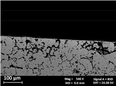
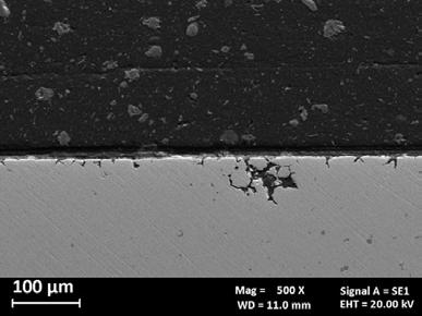
Fig.4 - SEM images of produced alloy 625 after intergranular corrosion tests. a) metallographic section of the surface along the building direction, b) metallographic section of the surface perpendicular to the building direction.
Fig. 4 show the SEM images of the corrosion morphology of the MFFF-processed specimen after the test. A different morphology was observed on the two main development planes. Only isolated attacks were observed on the surface parallel to the building direction (Fig. 4b). Conversely Fig. 4b showed a higher number of attacks on the surface perpendicular to the building direction, thus confirming that the corrosion behavior is strictly dependent upon the process parameters of the AM technologies adopted. Some examples of potentiodynamic polarization curves are shown in Fig. 5. Fig. 5a shows the results of the potentiodynamic polarization tests in 1 N H2SO4 solution (ASTM G5 (2)) for the specimens obtained by means of MFFF and LPBF and for comparison that of the HW. All the curves show a passive behavior over a wide range of potentials up to an increase in the anodic current density for potential values corresponding to the development of oxygen. This
behavior indicates that in this environment the alloy does not undergo corrosion, thus confirming the results obtained in a previous work (8). Similar results were observed for the MFFF- and LPBF-manufactured specimens in neutral chloride solu-tion in Fig. 5b. The free corrosion potentials were lower than those obtained in the 1N H2SO4 solution. The anodic polarization curves showed a wide range of passivity that ended at potential values equal to about +0.5 V vs SCE. This value is lower than the oxygen development potential, indicating the dissolution of the alloy under transpassive conditions. However, by reversing the scanning, the absence of a hysteresis loop and a repassivation potential significantly higher than the initial free corrosion potential is observed. Even in this case, no difference between the specimens obtained by means MFFF and LPBF was observed.
(a) (b)
(c)
Fig.5 - Potentiodynamic polarization curves of Alloy 625 specimens. a) in H2SO4 1N, according to ASTM G5 standard (2), b) in neutral 0.6 M NaCl, c) in acidified 0.6 M NaCl at pH 3. Potentiodynamic tests carried out in 0.6 M NaCl solution at pH 3 showed a free corrosion potential higher than that observed in neutral chloride solution. In this case, a difference between the LPBF and MFFF specimens was observed. The LPBF-manufactured specimen maintain a passive behavior up to the potential of about 0.6 V vs. SCE, after which the anodic current density increases to reach the transpassivity value. The reverse scan curve shows a repassivation without hysteresis and a repassivation potential equal to about 0.5 V vs SCE slightly higher than that one observed in solution at pH 7. Conversely, the specimens
obtained by means MFFF show a trend like LPBF only up to potential slightly higher than the free corrosion potential, beyond which a gradual increase in the anodic current density is observed. This deviation increases as the applied potential increases, until the transpassivity potential is sharply reached. The reverse scan curve shows a large hysteresis and repassivation at a lower potential than that one observed on LPBF specimens. This behavior is due to the initiation of crevice corrosion under the gasket in correspondence with a defect present on the surface of the sample as shown in Fig. 6.
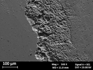
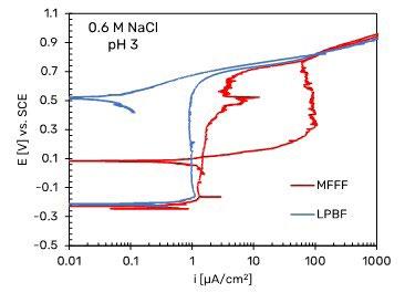
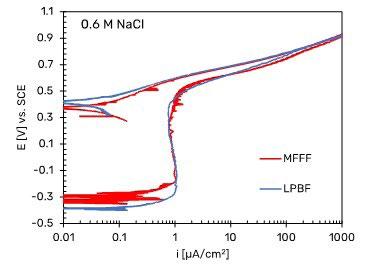
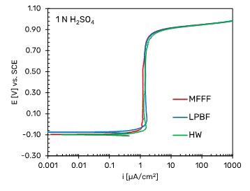
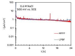
Fig. 7 shows some examples of potentiostatic polarization curves obtained at +200 mV vs SCE in neutral and acidified chloride solutions and at +500 mV vs SCE in neutral 0.6 M NaCl solution.
(a) (b) (c)
Fig.7 - Potentiostatic polarization curves of Alloy 625 specimens. a) +200 mV vs SCE in neutral 0.6 M NaCl, b) +200 mV vs SCE in acidified 0.6 M NaCl at pH 3, c) +500 mV vs SCE in neutral 0.6 M NaCl.
Fig. 7a and b show that the passivity current density for both the MFFF and LPBF specimens is an order of magnitude lower than the current density in the passivity section obtained in the potentiodynamic tests. This is due to the fact that potentiodynamic tests do not allow to evaluate the passive current since they are non-stationary methods. In general, it is observed that the passivity current density value is lower for the LPBF-manufactured specimens than for the MFFF-processed ones, demonstrating a greater corrosion resistance under these conditions. In the tests carried out at +500 mV vs SCE in neutral chloride solution no differences were found between the two AM techniques (Fig. 7c). At this potential value, the passivity current density is an order of magnitude greater than that obtained at +200 mV vs SCE.
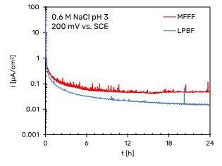
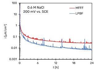
In none of the tests carried out a rapid increase in current was observed, thus indicating the absence of a trigger of localized corrosion (pitting or crevice). The presence of
many spikes of current density was ob-served, corresponding to the propagation and rapid repassivation of metastable pits (14).
Further potentiostatic tests are planned to investigate the corrosion behavior of alloy 625 produced by addi-tive technologies even at +500 mV vs. SCE.
CONCLUSION
The effect of macro- and microstructural features on the general and localized corrosion behavior of Alloy 625 obtained by means LPBF and MFFF were investigated. The results can be summarized as follows:
• The microstructure is strictly dependent upon the manufacturing technology adopted. In particular, the microstructure of MFFF specimen comprises equiaxial austenite grains coarser than hot rolled alloy 625.
• MFFF-built specimens were characterized by a higher porosity than LPBF with the evidence of continuous
pattern of defects due to incomplete densification of the green part during the sintering process.
• Intergranular corrosion susceptibility tests carried revealed higher corrosion rate of MFFF sample, but only superficial and no high penetrating attack was observed.
• Potentiodynamic tests in H2SO4 1N and neutral chloride solution showed a passive behavior of Alloy 625 over a wide range of potential, thus confirming the very high corrosion resistance in these environments.
• In acidified chloride solution at pH 3 the presence of crevice attack on MFFF specimens was detected.
REFERENCES
[1] ASTM International. ASTM G28-02(2015): Standard Test Methods for Detecting Suscepti-bility to Intergranular Corrosion in Wrought, Nickel-Rich, Chromium-Bearing Alloys. 2016; Available from: https://www.astm.org/g0028-02r15.html
[2] ASTM International. ASTM G5-14(2021): Standard Reference Test Method for Making Po-tentiodynamic Anodic Polarization Measurements. 2021; Available from: https://www.astm.org/g0005-14r21.html
[3] Sandhu SS, Shahi AS. Metallurgical, wear and fatigue performance of Inconel 625 weld claddings. J Mater Process Technol. 2016 Jul 1;233:1–8.
[4] Yin ZF, Zhao WZ, Lai WY, Zhao XH. Electrochemical behaviour of Ni-base alloys exposed under oil/gas field environments. Corros Sci. 2009 Aug;51(8):1702–6.
[5] Brownlee JK, Flesner KO, Riggs KR, Miglin BP. Selection and Qualification of Materials for HPHT Wells. Society of Petroleum Engineers - SPE High Pressure/High Temperature Sour Well Design Applied Technology Workshop 2005, HPHT 2005. 2005 May 17;
[6] Rai SK, Kumar A, Shankar V, Jayakumar T, Rao KBS, Raj B. Characterization of micro-structures in Inconel 625 using X-ray diffraction peak broadening and lattice parameter measurements. Scr Mater. 2004 Jul 1;51(1):59–63.
[7] Nagarajan B, Hu Z, Song X, Zhai W, Wei J. Development of Micro Selective Laser Melt-ing: The State of the Art and Future Perspectives. Engineering. 2019 Aug 1;5(4):702–20.
[8] Cabrini M, Lorenzi S, Testa C, Pastore T, Brevi F, Biamino S, et al. Evaluation of Corrosion Resistance of Alloy 625 Obtained by Laser Powder Bed Fusion. J Electrochem Soc. 2019 Jun 12;166(11):C3399–408.
[9] Cabrini M, Lorenzi S, Testa C, Brevi F, Biamino S, Fino P, et al. Microstructure and Selec-tive Corrosion of Alloy 625 Obtained by Means of Laser Powder Bed Fusion. Materials 2019, Vol 12, Page 1742. 2019 May 29;12(11):1742.
[10] ASTM International. ASTM B443-19: Standard Specification for Nickel-Chromium-Molybdenum-Columbium Alloy and NickelChromium-Molybdenum-Silicon Alloy Plate, Sheet, and Strip. 2019; Available from: https://www.astm.org/b0443-19.html
[11] Material datasheet Inconel 625. Available from: https://static.markforged.com/downloads/Inconel-625.pdf
[12] ASTM International. ASTM B446-19: Standard Specification for Nickel-Chromium-Molybdenum-Columbium Alloy (UNS N06625), Nickel-Chromium-Molybdenum-Silicon Alloy (UNS N06219), and Nickel-Chromium-Molybdenum-Tungsten Alloy (UNS N06650) Rod and Bar. 2019; Available from: https://www.astm.org/b0446-19.html
[13] Marchese G, Colera G, Calignano F, Lorusso M, Biamino S, Minetola P, et al. Characteriza-tion and Comparison of Inconel 625 Processed by Selective Laser Melting and Laser Metal Deposition, Adv. Eng. Mater., 19: 1600635, 2016. https://doi.org/10.1002/ adem.201600635
[14] Lutton Cwalina K, Demarest CR, Gerard AY, Scully JR. Revisiting the effects of molyb-denum and tungsten alloying on corrosion behavior of nickel-chromium alloys in aqueous corrosion. Curr Opin Solid State Mater Sci. 2019 Jun 1;23(3):129–41.
Organised by
Six years after the successful first conference on the topic, AIM, in cooperation with its sister society ASMET, organises once again a twoday event focused on the Surface Quality of continuously cast products.

The surface quality of ingots, billets, blooms and slabs is a particularly important issue in order to insure the required surface quality of final rolled and forged products. This aspect is becoming increasingly significant especially nowadays, when a lot of steelmakers are refocusing their activity on the search for better surface quality or new specialty steels requiring high quality surface features. All this lays on a table of new challenges faced by steelmaking industries, when energy efficiency and consequently lower environmental impact are concerned.
This international meeting aims at sharing the knowledge about the improvement of the surface quality of the continuously cast products and this scope will be achieved by clear expositions about:

• recent advances on the defect analysis;
• the root cause of the defects;
• innovative lubricating products;
• operations and maintenance;
• application of electromagnetic devices;
• AI applications, simulation and computing methods.
Prospective authors wishing to present are invited to submit a tentative title and an abstract of maximum 400 words (in English) to the Organising Secretariat (met@aimnet.it).
The abstract should provide sufficient information for a fair assessment. Two ways to submit papers will be available:
• to fill in the form online >> www.aimnet.it/iwsq-2.htm
• to send the title and the abstract, together with the requested information (Name and Surname, Affiliation, Mailing Address, Phone, Fax and e-mail) by e-mail to: met@aimnet.it
The Conference will be held in Bergamo at the Congress Center Giovanni XXIII, viale Papa Giovanni XXIII, 106 (http://www.congresscenter.bg.it).
Bergamo greets visitors with its Venetian Walls. Surrounded by rivers and lush, verdant valleys, crossed by paths that widen to Parco dei Colli, the area’s largest park, the city looks like a lounge filed with art, culture and nature, with a fascinating and complex history just waiting to be shared with others. The “upper and lower” city reveals a mixture of pleasant surprises and unexpected encounters, such as those with Gaetano Donizetti, the great composer of international renown, Bartolomeo Colleoni, the Bergamo leader who served under the Republic of Venice and Lorenzo Lotto, among the most famous Italian Renaissance artists who lived and worked in Bergamo for over a decade.
www.aimnet.it/iwsq-2.htm
Effect of multi-pass cold rolling on the corrosion properties of 2101 duplex stainless steel
edited by: L. Pezzato, C. Gennari, A.G. Settimi, I. Calliari, A. Kemény, I. MészárosDuplex stainless steels (DSS) are increasingly employed in the industry based on their combination of good mechanical properties and high corrosion resistance. These properties are achieved by stabilising quasi-equal volume fractions of the austenitic and ferritic phases at room temperature. The pitting resistance of a DSS is influenced by its chemical composition, presence of second phases, heat treatment, grain size, cold working, as-well-as surface roughness. In this research, LDX 2101 (EN 1.4162) lean DSS is investigated at different grades of cold deformation (thickness reduction from 9% to 61%), obtained by multi-pass cold rolling. The effect of this type of cold-working method on the corrosion properties of the material was evaluated by means of potentiodynamic polarization tests at room temperature in 3.5 wt.% NaCl solution and of critical pitting temperature (CPT) evaluation in 1 M NaCl solution. The results of the corrosion tests were also linked with proper OM and SEM microstructural observation and with results of XRD tests. The results showed that the multi-pass cold rolling does not affect the corrosion properties of the investigated material with deformation steps that are <10%. Corresponding to this finding, the microstructural and phase analysis investigations proved that no strain-induced martensite was formed during the process. The obtained results were also compared with single-pass cold-rolled properties of the material from a previous study pf the authors. As an effect of single-pass cold rolling, the same DSS (LDX2101) suffers a significant decrease of the CPT and destabilisation of the protective oxide layer with the thickness reduction. Therefore, this research shows that it is advisable to use multi-pass cold rolling instead of the single-pass method to reach high deformations without the deterioration of corrosion properties.
INTRODUCTION
Duplex Stainless steels (DSSs) are a category of high-alloyed steels characterized by a biphasic austeno-ferritic (c/a) microstructure obtained from a proper solution treatment after the forming operations. The presence of an equal volume fraction of the phases provides the best combination of mechanical and corrosion-resistance properties, making DSSs very interesting materials, especially for structural and special applications in aggressive environments. However, owing to the presence of the metastable austenitic phase and to the instability of ferrite at high temperatures, these steels are sensitive to diffusive and diffusionless phase transformations. (1–4) The eutectoidic decomposition of ferrite in the temperature range of 523 K to 1273 K (250 C to 1000 C) and its nitrogen-supersaturated condition are the main causes for precipitation of dangerous secondary phases. Further, the possibility of
Luca Pezzato, Claudio Gennari, Alessio Giorgio Settimi, Irene Calliari
department Of Industrial Engineering, University Of Padua, Via Marzolo 9., I-35131 Padova, Italy
luca.pezzato@unipd.it
Alexandra Kemény
department Of Materials Science And Engineering, Faculty Of Mechanical Engineering, Budapest University Of Technology And Economics, Műegyetem Rkp. 3., H-1111 Budapest, Hungary; mta-Bme Lendület Composite Metal Foams Research Group, Műegyetem Rkp. 3., H-1111 Budapest, Hungary
István Mészáros
department Of Materials Science And Engineering, Faculty Of Mechanical Engineering, Budapest University Of Technology And Economics, Műegyetem Rkp. 3., H-1111 Budapest, Hungary
strain-induced martensite (SIM) formation from cold-worked austenite cannot be neglected if the phase is not adequately stabilized. (5) Both the fact can negatively affect the corrosion properties of the DSS. In particular the presence of secondary phases negatively affect the corrosion properties of the material due to the local depletion of Cr from the matrix (6) whereas the formation of the Strain-Induced Martensite (SIM) from the metastable austenite can substantially affect the pitting resistance of stainless steels (7), because the number of the active anodic sites in the surface are increased (8,9). Thickness, composition and uniformity of the passive layer are modified in different extent by plastic deformation (10,11) and the increasing in dislocation density favors the film dissolution, due to the presence of lower binding energy regions, if compared to a perfect cry-
stal. In a previous work (12), the authors study the influence of single-pass cold rolling on the corrosion properties of different DSS, however a change in deformation mode influences SIM formation, causing a stress-state dependence of transformation kinetics. In the present work, the pitting resistance of 2101 DSS in as-received conditions and after multi step cold rolling is presented an compared with the ones previously obtained after single pass cold rolling with the aim to highlight the effects of different cold deformation modes on the corrosion behavior of lean duplex stainless steel.
MATERIALS AND METHODS
Chemical composition of 2101 steel is reported in Table 1.
Tab.1 - Chemical composition of 2101 DSS.
70,85 0,028 0,669 4,61 0,026 0,003 21,26 0,20 1,60 0,022 0,316 0,248
The as-received materials were cold rolled at various deformation degrees (from 9% to 61% of thickness reduction). The starting thickness of the sheet was 4 mm and each reduction were obtained with multi-pass mode with 0.25 mm of reduction for each pass. The samples after the various thickness reduction were polished with standard metallographic techniques (grinding with abrasive paper and polished with clothes and diamond suspensions) and the microstructure was studied by means of optical and electron microscope observation. The etched microstructures (Beraha’s etching) were observed using a Leica Cambridge Stereoscan 440 scanning electron microscope (SEM; Cambridge Instruments Ltd., Cambridge, UK) whereas for OM observation a Leica DMR light optical microscope (OM; Leica Microsystems, Wetzlar, Germany) was employed. Austenite/ferrite ratio in the different samples was evaluated with XRD measurements using a siemens D500 diffractometer (Siemens Corporation, Cherry Hill, NJ) using Cu Ka radiation (step size of 0.05 deg and 5 seconds of counting time for each step). Vickers Micro-Hardness tests were performed on both the phases in the different samples. Corrosion resistance of the as-received material
and of the samples after the cold deformation process was analyzed with potentiodynamic polarization tests (PDP) and critical pitting temperature tests (CPT). Potentiodynamic polarization tests were performed using an AMEL 2549 potentiostat and by immersing the samples in a pH 7 electrolyte solution composed by 35 g/l of NaCl in deionized water. All tests were conducted at room temperature, using calomel as reference electrode and platinum as counter electrode; for all tests, a scanning rate of 0.0005 V/s was applied. PDP tests were performed in triplicate to assure reproducibility and is reported one representative curve for each sample. The determination of the CPT was carried out by following the ASTM G150 standard (13), using a potentiostat/galvanostat AMEL 7060. The system consisted in two cells, containing the same aqueous solution (1 Molar of NaCl) and electrically connected by a salt bridge; in the first cell, maintained at room temperature, the reference electrode (calomel) was immersed, whereas the counter-electrode (platinum) and the sample were placed in the second, a thermostatic bath. The ASTM standard states the evaluation of the CPT by maintaining a constant potential of 700 mV and increasing the temperature of the
thermostatic cell at the rate of 1°C/min; the CPT is defined as the temperature at which the anodic current exceeds 100 μ A/cm2
RESULTS AND DISCUSSION
The as received sample (0% of thickness reduction) and the samples cold rolled with multipass rolling at 9, 24, 45 and
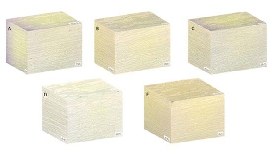
61% of thickness reduction were first of all observed at the OM and the results are reported in Fig.1. In all the samples both austenite and ferrite grains resulted elongated along the deformation direction. Increasing the thickness reduction, and in particular in the samples with 24, 45 and 61 % of thickness reduction, a fragmentation of the grains can be noted.
Fig.1 - OM micrographs of the samples with 0% (A), 9% (B), 24% (C), 45% (D) and 61% (E) of thickness reduction.
Considering the SEM micrographs, reported in Fig.2, can be noted in the images taken at lower magnification (sample 0% and 9%) the good balance between austenite and ferrite phases. Considering the more deformed samples
(24, 45 and 61 %) the SEM images taken at higher magnification evidence the presence of slip bands that also intersected between each other’s. This can be an indication of SIM formation but can also be due to deformation process.
Fig.2 - SEM micrographs of the samples with 0% (A), 9% (B), 24% (C), 45% (D) and 61% (E) of thickness reduction.
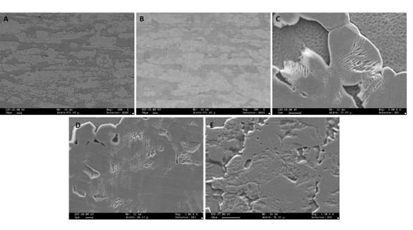
The hardness of the bulk and of the single phases (austenite and ferrite) was evaluated through Vickers microhardness tests and the values were obtained from an average of four total measurements and the results are reported in Fig.3. As can be observed the micro-hardness increases as the degree of deformation increases, or as the thickness of the various samples decreases. This behavior is related to the
increase in the work hardening of the material during the deformation process. Also, austenite/ferrite ratio was analyzed with X-ray diffraction method and the results are reported in Tab.2 but no significant trend between the relative quantity of the phases and the grade of deformation can be found.
Fig.3 - Micro-Hardness values recorded in the whole material in the samples with the various thickness reduction.
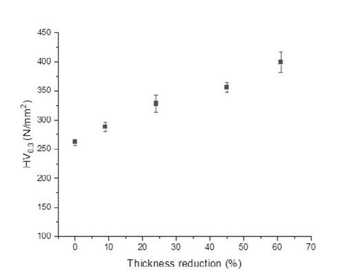
Tab.2 - Ferrite and austenite content evaluated through XRD method.
Sample Ferrite Content % Austenite Content % 0% 56 44 9% 50 50 24% 62 38 45% 68 32 61% 58 42
The corrosion resistance of the different samples was analyzed by means of PDP tests and CPT tests and the results are reported in Fig.4 and Tab.3. From the observation of the PDP curves cannot be observed a significant difference in the corrosion behavior of the samples with the different deformation grades. In fact, all the curves are substantially overlapped, with very similar values of corrosion potentials and corrosion current densities (see Tab.3 for the values) and also similar passive regions. Pitting potential for the as received sample and for the deformed samples is in the range 0.1-0.2 V Vs SCE, in accordance with previous work of the authors (6) and with the literature (14). The presence of pits was clearly observable on the samples surfaces after the test. Also, CPT values, recorded accordingly to ASTM G150 standard and reported in Tab.3, does not vary significantly with the deformation grade and remain in all the samples in a range between 13 and 16 °C that
are the standard for 2101 DSS. (6) Generally the presence of SIM remarkably reduces the corrosion properties of the material, so this result, together with the absence of a clear trend in the austenite/ferrite ratio, can be considered as an important indication of the fact that SIM probably is not formed in 2101 DSS with multi-pass cold rolling. In order to experimentally confirm the absence of SIM more advanced characterization technique (i.e. Neutron Diffraction) should be done. This result is the opposite of what was previously found by the authors with single pass cold rolling (5), this evidencing that the type of deformation plays a key role. In particular with single pass cold rolling was found a reduction of almost 50% of the CPT with 60% of cold deformation whereas with multi-pass cold rolling the CPT at 61% of thickness reduction was the same of the as received material.
Fig.4 - Potentiodynamic polarization plots recorded in 3.5% NaCl solution for the samples with the different thickness reduction.
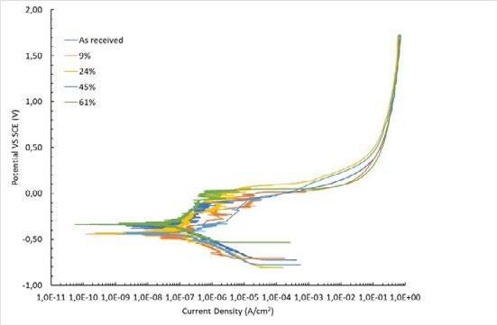
Tab.3 - Values of the corrosion potential, corrosion current density and of the critical pitting temperature for the samples with different thickness reduction.
Sample Ecorr (V) Icorr (A/cm2) T PIT (°C)
0% -0.34 1,90x10⁻⁷ 14 9% -0.44 1,50 x10⁻⁷ 16 24% -0.43 2,50 x10⁻⁷ 13 45% -0.46 2,20 x10⁻⁷ 15 61% -0.34 1,50 x10⁻⁷ 13
CONCLUSIONS
The cold plastic deformation of a lean DSS 2101, introduced by multi-pass cold rolling, did not affect the corrosion properties of the material. This can be related with the fact that probably deformation-induced martensite does not form with the multi-pass process. This fact is also confirmed by the XRD measurements, that does not evidence a clear correlation between deformation grade and austenite/ferrite ratio, and by the microstructural analysis that evidence only a slight fragmentation and elongation of the phases along the rolling direction. The results of this study were compared with the ones of another study of the authors in which the effect of single-pass rolling deformation on 2101 DSS was studied. In this case, the material undergoes a significant decrease in corrosion resistance, due to the formation of SIM during
the deformation process. Therefore, this work proves that it is more advantageous to use a multi-pass cold rolling rather than the single pass method to produce cold deformation on 2101DSS, as the first method does not negatively alter its corrosion properties.
ACKNOWLEDGEMENTS
Ing. Marco Frigo from Outokumpu is kindly acknowledged for providing the material for this study.
REFERENCES
[1] Alvarez-Armas I, Degallaix S. Duplex Stainless Steels [Internet]. Hoboken, New Jersey Usa: Wiley-VCH Verlag; 2009. 464 p. Available from: https://www.wiley.com/en-us/Duplex+Stainless+Steels-p-9781848211377
[2] Gunn RN. Duplex Stainless Steels Microstructure, Properties and Applications [Internet]. Cambridge UK: Woodhead Publishing; 1997. 204 p. Available from: https://www.sciencedirect.com/book/9781855733183/duplex-stainless-steels
[3] Nilsson JO. The physical metallurgy of duplex stainless steels. In: In Proceedings of the Duplex Stainless Steels 97: 5th World Conference. Maastricht; 1997. p. 73–82.
[4] Nilsson JO. Super duplex stainless steels. Mater Sci Technol (United Kingdom). 1992;8(8):685–700.
[5] Breda M, Brunelli K, Grazzi F, Scherillo A, Calliari I. Effects of Cold Rolling and Strain-Induced Martensite Formation in a SAF 2205 Duplex Stainless Steel. Metall Mater Trans A Phys Metall Mater Sci. 2015;46(2):577–86.
[6] Pezzato L, Lago M, Brunelli K, Breda M, Calliari I. Effect of the Heat Treatment on the Corrosion Resistance of Duplex Stainless Steels. J Mater Eng Perform [Internet]. 2018;27(8):3859–68. Available from: https://doi.org/10.1007/s11665-018-3408-5
[7] Gennari C, Lago M, Bögre B, Meszaros I, Calliari I, Pezzato L. Microstructural and corrosion properties of cold rolled laser welded UNS S32750 duplex stainless steel. Metals (Basel). 2018;8(2):1–17.
[8] Randak A, Trautes FW. Uber den EinfluB der Austenitstabilitiit von 18 / 8-Chrom- Nickel-Stahlen auf die Verformungseigenschafien und auf das Korrosionsverhalten dieser Stahle "). Mater Corros. 1970;21(2):97–109.
[9] Elayaperumal K, De PK, Balachandra J. Passivity of Type 304 Stainless Steel-Effect of Plastic Deformation. Vol. 28, Corrosion. 1972. p. 269–73.
[10] Phadnis S V., Satpati AK, Muthe KP, Vyas JC, Sundaresan RI. Comparison of rolled and heat treated SS304 in chloride solution using electrochemical and XPS techniques. Corros Sci. 2003;45(11):2467–83.
[11] Naval F. Effects of tensile and compressive stresses on the passive layers formed on a type 302 stainless steel in a normal sulphuric acid bath. Vol. 30, Journal of Materials Science. 1995. p. 1166–72.
[12] Breda M, Pezzato L, Pizzo M, Calliari I. Effect of cold rolling on pitting resistance in duplex stainless steels. Metall Ital. 2014;106(6):15–9.
[13] ASTM-G150 Standard Test Method for Electrochemical Critical Pitting Temperature Testing of Stainless Steels and Related Alloys-2018 Edition
[14] Huang TS, Tsai WT, Pan SJ, Chang KC. Pitting corrosion behavior of 2101 duplex stainless steel in chloride solutions. Corrosion Engineering, Science and Technology. 2018; 53:9-15
ALL'INDICE >Field experience - localized corrosion behavior of lean duplex stainless steel DX2202 in urban wastewater treatment plants
edited by: A. Allion, C. David, B. Emo, N. LarchéThanks to their good corrosion resistance and ease to shape and weld, austenitic stainless steel grades (e.g. EN 1.4404 / 316 L / UNS S31603) are used as standard materials for the construction of urban wastewater treatment plants (WWTP). The main factors influencing the corrosiveness of the fluids in WWTP are halide concentration (more specifically chlorides), H2S, low pH, high temperature and their combined action. Considering the comprehension of moderate material cost, good corrosion resistance and high mechanical properties, lean duplex stainless steels are good alternatives to the commonly used austenitic grades, but they are still too rarely chosen, probably due to a lack of case studies. To define the limit of use of lean duplex stainless steels for urban wastewater treatment units, a European project was initiated, involving stainless steel manufacturers, end-users, corrosion and microbiological laboratories.
The present paper deals with the localized corrosion performance of lean duplex EN 1.4062 / DX2202 / UNS S32202 in solutions simulating pre-treatment unit waters, compared to the austenitic stainless steel 316 L and the more alloyed duplex grade EN 1.4462 / DX2205 / UNS S32205. Crevice corrosion testing was performed using crevice formers defined in ISO 18070:2015. Both laboratory screen tests and field exposure in urban wastewater treatment plants were performed. This study confirms that lean duplex grade DX2202 can be used as an alternative to 316 L in aerated wet atmospheres in case of moderate contamination of H2S (<10 ppm) and chloride (<200 ppm). For higher contaminations (e.g. H2S around 100 ppm and chloride content around 1000 ppm) the duplex grade DX2205 should be preferred.
KEYWORDS:
STAINLESS STEEL, LEAN DUPLEX, URBAN WASTEWATER TREATMENT PLANT, CORROSION RESISTANCE, CREVICE CORROSION, CHLORIDE CONTENT, H2S;
INTRODUCTION
For several decades, traditional austenitic stainless steel grades (304 L, 316 L) are a material of choice for the water and wastewater industry especially thanks to their very good resistance to localized corrosion in the presence of chlorides [1]. This type of material is used in a high number of related applications: tubing, tanks and machinery for screening, washing, compacting, dewatering and so forth (Figure 1). It is also used in auxiliary equipment, such as stairs and handrails [2,3].
Fig.1 - Examples of equipment made of stainless steel (from the left to the right): Flotation unit, anaerobic digestion tower, silo decanter, biodigester.
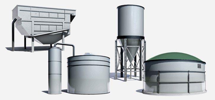
In most cases, the nature of urban wastewater does not present major corrosion issues for these common austenitic grades. However, under specific conditions, the chloride and the H2S concentrations can reach critical values inconsistent with the use of these alloys.
Chloride is known to be one of the critical agents affecting the stability of protective passive layers for stainless steels [4]. Usually, the chloride content in municipal wastewater streams, around 50-200 mg/L, does not present major issues for austenitic grade such as 3048 L. However, in certain conditions, chloride concentrations can reach 3 000 - 6 000 mg/L and in extreme cases 10 000 mg/L for seaside-located facilities or when de-icing salts are used during winter [5,6] requiring more corrosion resistant alloys.
H2S is an acidic gas that will, when combined with moisture, acidify moist film at the metal surface. This results in lowering the pitting potential of the material and therefore decreases its corrosion tolerance, especially toward chlorides [7]. Dry H2S has little impact on stainless 304L and 316L in terms of corrosion. 316 L is the reference material for moist H2S. But when 316 L is exposed atmospherically to H2S with chlorides (splash zones, or marine atmosphere), problems can occur and more corrosion resistant alloys shall be selected, including duplex (austeno–ferritic) stainless steels.
Considering the comprehension of economic cost, good
corrosion resistance and higher mechanical properties, the more recently developed lean duplex stainless steel (DX2202) can be a good alternative to the commonly used austenitic grade (316 L) but is still too rarely chosen, due to rare field experiences in the wastewater industry area. In view of defining the limit of use of selected lean duplex stainless steel grades for urban wastewater treatment units, a European project [8] was initiated, involving stainless steel manufacturers, end-users, corrosion and microbiological laboratories. Both laboratory screen tests and field exposure in urban wastewater treatment plants were performed [9,10]. The experiments carried out during this project aim at bringing data for better framing lean duplex stainless steels limits for wastewater applications, and compare them to commonly used austenitic grades.
The present paper deals with the localized corrosion performance of lean duplex DX2202 in solutions simulating pre-treatment unit waters. Results were compared with the austenitic stainless steel 316 L and with the more alloyed duplex grade DX2205. Crevice corrosion testing was performed using crevice formers defined in ISO 18070:2015. Exposures of crevice coupons in field municipal wastewater plants were also conducted for 1 year in a low chloride content unit (Brussels, Belgium) and in a high chloride content unit (Cap Sicié, near Toulon, France).
MATERIALS AND METHODS Materials
The following lean duplex stainless steel grade was sup-
plied for this project: DX2202 (UNS S32202, EN 1.4062), together with a duplex stainless steel grade DX2205 (UNS S32205, EN 1.4462). The austenitic stainless steel grade 316 L (UNS S31603, EN 1.4404) was used as reference material. All are industrial cold rolled materials with a 2E surface fini-
sh and a plate thickness of 3 mm. Table 1 gives the chemical composition of the tested alloys and their pitting resistance equivalent number (PREN).
Tab.1 - Chemical composition (%w) of the selected grades and PREN (%C + 3.3%Mo + 16%N).
Grades 316 L DX2202 DX2205
UNS S31603 S32202 S32205 EN 1.4404 1.4062 1.4462 C 0.0248 0.0225 0.0134 Cr 16.7 23.1 22.7 Ni 10.0 2.6 5.5 Mo 2.0 0.2 3.1 N 0.0498 0.1923 0.1710 Mn 1.2 1.3 1.8 S 0.0016 0.0005 0.0006 P 0.03 0.03 0.03 Fe Bal. Bal. Bal. PREN 24 27 35
The PREN formula is often used to estimate the localized corrosion resistance ranges of stainless steel from their chemical composition. It is given by PREN = %Cr + 3.3(%Mo) + 16(%N). The PREN must be used with care since this number does not consider other very important parameters, such as the metallurgical state of the alloy, the nickel content, or the surface state. The surface finishes were “as-received” with Ra at 3 ± 1 μ m. The metallographic inspections indicated normal microstructures for these materials. The ferrite fraction represents 55% and 50% for DX2202 an DX2205 respectively. Samples were cut to 150 × 100 mm. All cut edges were polished to P600. Holes were drilled to hold samples and to set crevice formers when needed.
Crevice assembly
The risk of crevice corrosion was evaluated using crevice formers simulating service conditions in confined environ-
ments (e.g., crevice geometry that may be encountered below a given gasket material). Standard crevice assemblies were used for this purpose, according to ISO 18070:2015 [11]. With this assembly, a rather well-defined crevice geometry can be obtained with a controlled pressure at the gasket location. It has the following characteristics: Crevice formers are made of polyvinylidene fluoride (PVDF), all fasteners are made of titanium grade 2, electrically isolated from the tested specimen, and disc springs are used to keep a measurable and constant pressure between the crevice formers and the specimen. The crevice formers were tightened to the test specimens with a force of about 900 N (i.e. a pressure of about 3 N/mm²), which corresponds to a torque of 3 N·m on the used fasteners. A schematic representation and a picture of the crevice assembly are shown in Figure 2. The anode (surface under crevice formers) to cathode (surface in contact with the bulk environment) ratio was about 1:30.
Fig.2 - Schematic representation and picture of the crevice assembly ISO 18070:2015 [11].
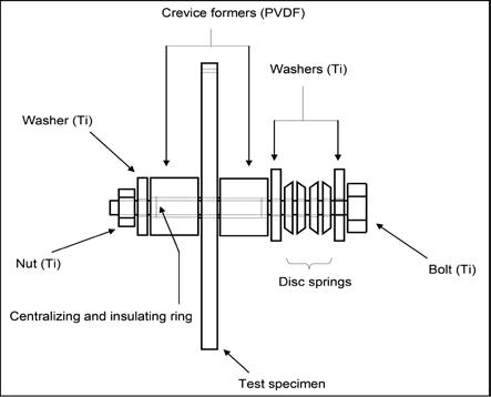
EXPOSURE CONDITIONS Laboratory exposures
a.
Corrosion resistance in immersion
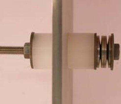
All exposures were performed at the open-circuit potential. The tested chloride contents ranged from 200 ppm to 3000 ppm, for two tested temperatures at 35°C and 50°C. All tests were performed at saturated dissolved oxygen using continuous air bubbling. For each test condition, the exposure duration was 30 days. Five replicates were used per tested alloy for crevice samples. Two regulated exposure tanks (1000 L) have been specifically designed for the corrosion tests. The heating was controlled with the use of titanium heaters and the homogeneity in temperature was ensured with permanent stirring pumps. The chloride concentrations were reached by mixing demineralized water (0.1 μ s/cm) with NaCl reagent grade. The pH was adjusted and controlled to pH 6.0 ± 0.2 using punctual addition of hydrochloric acid 0.1 N.
b. Corrosion resistance in atmospheric conditions with H2S
Corrosion tests in the moist environment were implemented to simulate the conditions of exposure of materials in humid units that can generate H2S gas. The test vessel consisted of a sealed glass cell with the specimens suspended from the cover and exposed to the atmosphere in equilibrium with a saturated K2SO4 solution to ensure a relative humidity (RH) of 97% in the headspace of the cell.
The test matrix has been defined from the collected field data (survey from Veolia wastewater plants) in terms of possible ranges in chloride and H2S contents. The selected conditions are given in Tab. 2. In all cases, the start of the tests was defined as the time when the outgoing gas composition reached the target values. Four replicates have been tested for each test condition and alloy.
Tab.2 - Test conditions for corrosion tests in presence of H2S in moist environments.
Abbreviation: WWTP; wastewater treatment plant.
WWTP / gas phase
Field exposures
Two sites have been selected for real condition exposures to represent standard and harsh conditions. These sites are:
- The Brussels municipal WWTP (Belgium)
- The coastal Cap Sicié WWTP (near Toulon, France)
Tab.3 - Main characteristics of the units used for field exposures.
Coupons were exposed in immersed conditions in the pretreatment buildings at the inlet works (screen step to remove large particles) and in wet conditions, at approximately 1 meter above the water level. The main characteristics and environmental conditions of the two units are given in Table 3. Brussels WWTP Cap Sicié WWTP
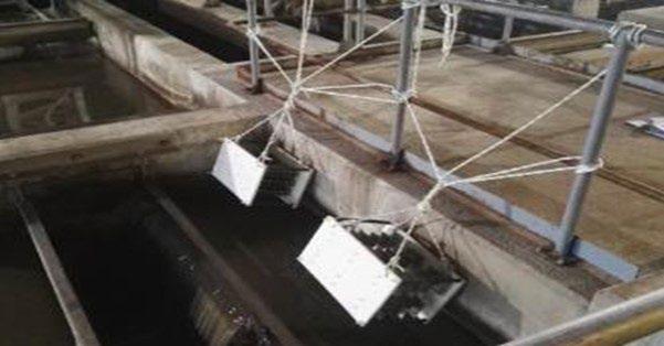
Capacity (eq. inhabitants) 1.4M 0.5M Year of construction 2007 1998
Temperature range (°C) 10-20°C 10-30°C pH range 6-8 6-8
Chloride mean/(max) (ppm) 160/(400) 2470/(4100)
H2S gaseous range (ppm) 2-10 5-100
The concentrations of chloride and H2S are about 10 times higher in Cap Sicié compared to Brussels WWTP. The samples have been installed on structural modules for
exposure in immersion and in atmosphere. For all alloys, five replicates of crevice samples have been tested.
Fig.3 - Illustration of the field exposure of corrosion modules at the Brussels WWTP.
RESULTS – DISCUSSION
Exposures in simulated solutions
Corrosion resistance in immersion
The crevice corrosion results obtained with ISO18070:2015 crevice assembly are given in Table 4 and Table 5. They indicate the total number of corroded specimens (out of the 5 tested replicates) and the maximum corrosion attacks
for the less corroded replicates and the most corroded replicate (reported as min. and max. corrosion attack respectively). A typical aspect of the corroded alloys after exposures at 35°C/3000-ppm Cl /pH 6 and 50°C/500-ppm Cl /pH 6 are presented in Figures 3 and 4, respectively.
The results show that localized corrosion, when initiated,
always occurred below gaskets (crevice corrosion) close to the interface with the bulk environment, whatever the tested condition and the alloy.
Tab.4 - Crevice corrosion results using ISO18070:2015 crevice assemblies—the number of crevice samples is indicated (x/5) together with minimum and maximum crevice depth measured on five replicates after 1 month of immersion at 35°C, pH 6.
Tab.5 - Crevice corrosion results using ISO18070:2015 crevice assemblies—the number of crevice samples is indicated (x/5) together with minimum and maximum crevice depth measured on five replicates after 1 month of immersion at 50°C, pH 6.
At 35°C and 50°C, no crevice corrosion initiated on any tested alloys at a chloride content of 200 ppm. For a chloride content of 500 ppm, 316 L and DX2202 showed only superficial attacks. Superficial attack or etching corresponds to limited corrosion pits, below 25 µ m, without

propagation according to the MTI procedure for localized corrosion assessment [12]. Under the same test conditions, DX2205 resisted crevice corrosion both at 35°C and 50°C. At 50°C, the DX2205 only failed at 3000 ppm.
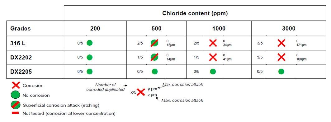
Fig.4 - Typical aspect of corroded samples after exposure in condition 3000ppm Cl-, 35°C, pH 6 with ISO18070:2015 crevice assembly.
Fig.5 - Typical aspect of corroded samples after exposure in condition 500ppm Cl, 50°C, pH 6 with ISO18070:2015 crevice assembly.
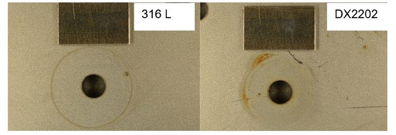
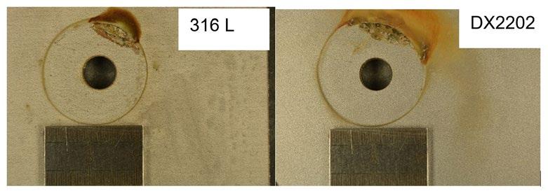
The results draw rather clear trends regarding the limits of use of tested alloys in terms of resistance to localized corrosion, since the corrosion of one replicate is enough to indicate that the alloy is potentially susceptible to localized in the concerned condition. DX2202 presents a moderate crevice corrosion resistance, at the same level that of 316 L for the tested conditions. DX2205 is the gra-
de that exhibits the highest crevice corrosion resistance in the tested experimental conditions.
Corrosion resistance in atmospheric conditions with H2S
The crevice corrosion results for all test conditions in moist H2S are summarized in Table 6.
Tab.6 - Crevice corrosion results after 1 month of exposure in conditions #A, #B, #C, and #D with ISO18070:2015 crevice assembly.
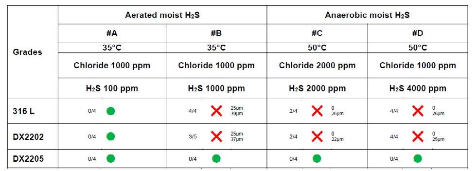
In aerobic tests conditions, at low H2S content (100ppm), no corrosion occurred. The increase of H2S content, from 100ppm to 1000ppm significantly affected the crevice corrosion resistance of the tested alloys (316 L and DX2202) except for DX2205 that still resisted to crevice corrosion. In anaerobic tests conditions, the lean duplex DX2202 and the commonly used austenitic 316 L grades showed crevice corrosion; while the duplex DX2205 grade is resistant to crevice corrosion.
Field exposure results
The corrosion results from field exposure tests in Brussels WWTP and in Cap Sicié WWTP are given in Tables 7 and 8 for immersed samples and samples exposed in moist environment respectively.

Corrosion resistance in immersion
Tab.7 - Crevice corrosion results after 1-year exposure in pretreatment units of the wastewater treatment plants (WWTP) in Brussels (mean chloride 160 ppm) and in Cap Sicié (mean chloride 2470 ppm) with ISO18070:2015 crevice assembly; immersed samples.
The crevice corrosion resistance of all the alloys is good when samples were immersed in Brussels plant while only DX2205 resisted corrosion when immersed in Cap
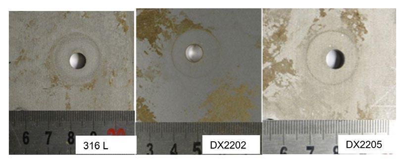
Sicié plant. One can note that only sludge was observed on samples immersed in Brussels plant
Fig.6 - Typical aspect of samples after 1-year immersion in the pretreatment unit of the Brussels plant.
Fig.7 - Typical aspect of corroded samples after 1-year immersion in the pretreatment unit of the Cap Sicié plant.
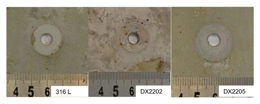
The localized corrosion results are in very good line with the ones obtained in simulated waters showing the closest chloride content at 35°C for Brussels and for Cap Sicié, respectively (Table 4).
Corrosion resistance in atmospheric conditions with H2S
The corrosion results (wet conditions with samples exposed 1 meter above water level) from field exposure tests in Brussels WWTP and in Cap Sicié WWTP are given in Table 8.

Tab.8 - Crevice corrosion results after 1-year exposure in pretreatment unit of the wastewater treatment plants (WWTP) in Brussels (mean chloride 160 ppm) and in Cap Sicié (mean chloride 2470 ppm) with ISO18070:2015 crevice assembly; samples above the water level.
Fig.8 - Typical aspect of samples after 1-year exposure in pretreatment unit of the Brussels plant, 1 meter above the water level.
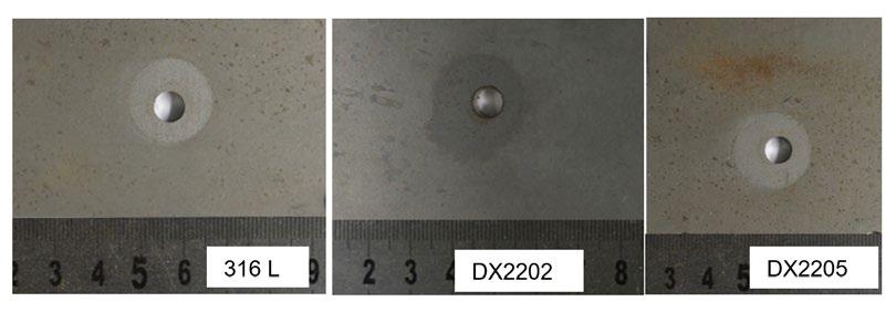
Fig.8 - Typical aspect of samples after 1-year exposure in pretreatment unit of the Cap Sicié plant, 1 meter above the water level.
No corrosion occurred on samples exposed in Brussels WWTP, as predicted from exposures in simulated water containing similar chloride content (Tab. 6). The results from Cap Sicié containing 10 times higher H2S content (Table 3) were much more severe. A depassivation of the surface occurred on 316 L and DX2202 which showed uniform and localized corrosion. The combination of H2S and oxygen in a wet atmosphere associated with chloride contamination is a severe cocktail for low-grade stainless steels. The corrosivity and observed depassivations (localized or generalized) might be attributed to the formation of corrosive compounds involving elemental sulfur, thiosulfate, and acidification processes in the presence of chloride. Deeper investigations would be required to assess the relative influence of these parameters and their synergy.
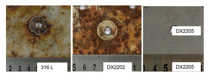
Under these severe conditions, only DX2205 resisted corrosion.
CONCLUSION
For all the tested conditions (immersion or moist environment, laboratory of field exposure), the EN 1.4062 / DX2202 / S32202 lean duplex showed similar corrosion resistance to the austenitic grade EN 1.4404 / 316L / 316 L. In Brussels where H2S content is low (2–10 ppm) and chloride below 200 ppm, all tested alloys resisted corrosion. In wet aerated conditions, the presence of H2S combined with NaCl contaminations (in the range of levels encountered in the Cap Sicié WWTP) was extremely severe for
EN 1.4404 / 316 L / UNS S31603 but also for the tested lean duplex EN 1.4062 / DX2202 / UNS S32202. These alloys cannot be recommended for harsh environments. EN 1.4062 / DX2202 / UNS S32202 can be used as alternative alloy to EN 1.4404 / 316 L / UNS S31603 grade in WWTP presenting standard conditions with limited chloride contamination (<200 ppm) and limited H2S content (<100 ppm) while EN 1.4462 / DX2205 / UNS S32205 should be preferred for harsh conditions. The results from field exposures (1 year) showed good correlation with the laboratory results in simulated environments, providing confidence in the test method for future investigations.
REFERENCES
[1] J.-M. Rovel, P. Mouchet, Water Treatment Handbook, 7th ed., Lavoisier, 2007.
[2] A.H. Tuthill, S. Lamb, Stainless Steel in Municipal WasteWater Treatment Plants, NiDi Tech. Ser. 10076 (1998).
[3] International Stainless Steel Forum, Stainless Steel in Sewage Treatment Plants: A Clean Solution for Pure Water, (2010).
[4] C.O.A. Olsson, D. Landolt, Passive films on stainless steels - Chemistry, structure and growth, Electrochim. Acta. 48 (2003) 1093–1104. https://doi.org/10.1016/S0013-4686(02)00841-1
[5] V.R. Kelly, G.M. Lovett, K.C. Weathers, S.E.G. Findlay, D.L. Strayer, D.J. Burns, G.E. Likens, Long-term sodium chloride retention in a rural watershed: Legacy effects of road salt on streamwater concentration, Environ. Sci. Technol. 42 (2008) 410–415. https://doi. org/10.1021/es071391l.
[6] J.B. Sérodes, S. Behmel, S. Simard, O. Laflamme, A. Grondin, C. Beaulieu, F. Proulx, M.J. Rodriguez, Tracking domestic wastewater and road de-icing salt in a municipal drinking water reservoir: Acesulfame and chloride as co-tracers, Water Res. 203 (2021). https:// doi.org/10.1016/j.watres.2021.117493.
[7] L. Cao, A. Anderko, F. Gui, N. Sridhar, Localized Corrosion of Corrosion Resistant Alloys in H 2 S-Containing Environments, 9312 (2016) 636–654.
[8] RFCS grant agreement number 749632, DUPLEXWASTE - Lean Duplex Stainless Steel for Urban and Industrial Waste Water, n.d.
[9] N. Larché, B. Emo, A. Allion, E. Johansson, D. Thierry, Localized corrosion of (lean) duplex stainless steels in immersion units of urban wastewater treatment plants, Mater. Corros. (2021). https://doi.org/10.1002/maco.202112298
[10] N. Larché, B. Emo, D. Thierry, V. Duquesnes, C. Mendibide, Localized corrosion of lean duplex stainless steels in H2S-containing wet atmosphere from urban wastewater treatment units, Mater. Corros. 72 (2021) 1730–1741. https://doi.org/10.1002/maco.202112508
[11] ISO 18070:2015 , Corrosion of metals and alloys - Crevice corrosion formers with disc springs for flat specimens or tubes of stainless steels in corrosive solutions, 2015.
[12] “Method MTI‐2 for laboratory testing of wrought iron and nickel‐base alloys for relative resistance to crevice corrosion in a standard ferric chloride solution,” in: Mater. Technol. Inst. Chem. Process Ind., n.d.: p. No. 3—appendix B.
Stato dell’arte sulle tecniche industriali per il recupero dei fanghi di decapaggio nel processo degli acciai inossidabili
a cura di: C. Tirasso, C. Rocchi, K. Brunelli
Nel processo di produzione degli acciai inossidabili, il decapaggio è un passaggio fondamentale per la rimozione della scaglia di ossido che si forma sulla superficie del materiale a seguito del precedente trattamento di ricottura. Con la progressiva dissoluzione della scaglia, il contenuto di metalli disciolti all’interno del bagno decapante aumenta: questo può diminuire l’efficienza della soluzione impiegata rendendo necessario scaricarla ad intervalli di tempo stabiliti. Questo step produttivo è inevitabilmente associato alla generazione di sottoprodotti inquinanti di natura solida, liquida o gassosa. Quindi, a causa della loro formulazione complessa e dannosa, è fondamentale valutarne l’impatto ambientale.
Negli ultimi anni, la comunità scientifica ha sviluppato nuove tecnologie per il recupero della frazione metallica (solida, sotto forma di fanghi) e/o acida (liquida) dalle soluzioni industriali esauste di decapaggio con l’intento di garantire un risparmio economico e di promuovere una produzione sostenibile dal punto di vista ambientale. Ad oggi vengono applicati diversi metodi di recupero che sfruttano tecniche di separazione sia chimica che fisica e che possono essere divisi in due gruppi: alcune tecniche recuperano solo la frazione acida, altre sia la frazione acida che metallica.
In questo articolo, verranno descritte le seguenti tematiche: la formazione dei fanghi di decapaggio e le loro proprietà chimico-fisiche insieme alle tecniche di recupero attualmente impiegate per il recupero della frazione metallica dai fanghi di decapaggio.
INTRODUZIONE
Gli acciai inossidabili sono impiegati in diverse applicazioni: nel settore chimico e farmaceutico, in campo edile e immobiliare, alimentare, dell’elettrodomestico e per ogni utilizzo che richiede un’elevata resistenza a corrosione e specifiche qualità estetiche [1]. Il cromo presente negli acciai inossidabili garantisce la formazione di uno strato passivo aderente che protegge la superficie del materiale. Generalmente è formato dalla specie chimica Cr2O3 con uno spessore di circa 2 nm [2]. Lo strato passivo può essere fisicamente danneggiato a seguito di trattamenti di riscaldo e di raffreddamento che caratterizzano il processo di produzione degli acciai inossidabili. Questi ultimi assicurano che il materiale incrudito recuperi un’idonea microstruttura [3] con relative caratteristiche meccaniche. Nel corso di questi processi, si formano uno o più strati di ossidi definiti come “scaglia di ossido” il cui spessore non supera i 500-600 nm [4]. Gli
Chiara Tirasso, Claudia Rocchi
Acciai Speciali Terni (AST) chiara.tirasso@acciaiterni.it claudia.rocchi@acciaiterni.it
Katya Brunelli
Università di Padova katya.brunelli@unipd.it
elementi costituenti sono legati al tipo di materiale prodotto e alla diffusione dei suoi elementi di lega attraverso la matrice di base. Nello specifico, la diffusione è influenzata dalle condizioni di ricottura (tempo, temperatura e atmosfera). Per esempio, acciai con un contenuto di Cr oltre il 13% hanno una scaglia formata da Cr2O3, (Cr,Fe)2O3 o nel composto più ricco in Cr (Cr, Fe, Mn)3O4 con uno strato esterno di Fe2O3 [5].
Quindi, a seguito del processo di ricottura, è necessario rimuovere la scaglia di ossido per ottenere una superficie uniforme ed omogenea.
La rimozione della stessa avviene mediante due step produttivi: il decapaggio meccanico e il decapaggio chimico. Questi ultimi vengono impiegati congiuntamente o meno a seconda della finitura superficiale del materiale. Dopo la laminazione a caldo e il successivo trattamento di ricottura, l’acciaio inossidabile è decapato sia meccanicamente che chimicamente. Questi due passaggi sono sequenziali. Invece, a seguito della laminazione a freddo e del successivo trattamento di ricottura, è previsto solo il decapaggio chimico [6].
Il decapaggio meccanico agisce sugli strati di ossido superficiali. Il decapaggio chimico invece, sfruttando soluzioni chimiche decapanti, lavora sulla matrice dell’acciaio inossidabile a diretto contatto con lo strato decromizzato situato all’interfaccia matrice-ossido che si forma nella fase precedente di ricottura.
Il decapaggio chimico impiega soluzioni acide concentrate che progressivamente si esauriscono con la formazione di sottoprodotti di scarto. Questo comporta una diminuzione significativa della velocità del processo di decapaggio.
Per questo motivo, le soluzioni decapanti necessitano di costanti aggiunte di reagenti freschi per garantire la stessa efficienza all’interno del processo. Si ha inoltre un progressivo aumento di scarti che vengono prodotti sotto forma di sali, ossidi di metalli e soluzioni acide esauste. Anche se a basse concentrazioni, questi componenti sono altamente corrosivi e inquinanti se rilasciati nell’am-
biente [7].
Le applicazioni industriali sviluppate per rendere il processo di decapaggio più eco-sostenibile sono principalmente focalizzate sul recupero degli acidi a partire dalla frazione liquida delle soluzioni esauste di decapaggio. Invece, la frazione solida presente, definita come “fango”, viene categorizzata come uno scarto con poche possibilità di riciclo nonostante contenga metalli di un certo valore da un punto di vista economico.
Questo perchè vi è una difficoltà di fondo nel selezionare una tecnica di rigenerazione “completa” essendoci diversi elementi costituenti, ciascuno nel proprio stato di ossidazione. Inoltre, possono essere trovati residui di altri componenti presenti nel bagno decapante come inibitori di corrosione, surfattanti e stabilizzatori che aumentano il livello di difficoltà in termini di un recupero efficiente degli elementi desiderati.
Generalmente viene impiegato il metodo della neutralizzazione da cui si ottengono sali che vengono opportunamente stoccati in apposite discariche collocate in prossimità del sito industriale. Questo anche se gli scarti in questione potrebbero essere una risorsa dal momento che contengono elementi metallici che potrebbero essere recuperati affinchè vengano reintrodotti nel ciclo di produzione degli acciai inossidabili.
FORMAZIONE E CARATTERIZZAZIONE DEI FANGHI DI DECAPAGGIO
Analizzando il processo di decapaggio industriale degli acciai inossidabili, ci sono due diversi passaggi in cui si generano fanghi da cui possono essere recuperati elementi da re-impiegare nel ciclo di produzione [8]:
(1) Il processo che avviene all’interno delle vasche di decapaggio con l’utilizzo di miscele di soluzioni acide. Da questo si ottengono principalmente metalli e i relativi ossidi provenienti dalla scaglia presente sulla superficie del materiale.
(2) Il processo che coinvolge gli impianti per il trattamento delle acque reflue dove vengono gestite due tipologie di sottoprodotti: le soluzioni acide esauste (se la frazione acida non è stata precedentemente già
trattata con una specifica tecnologia di recupero) e le acque acidule. Dagli impianti in questione si ottengono gli idrossidi dei metalli presenti nella soluzione decapante esausta e (CaSO4·2H2O).
Nel processo descritto al punto (1), il decapaggio chimico lavora sull’acciaio inossidabile tramite l’utilizzo di soluzioni acide costituite da acido nitrico HNO3 e acido fluoridrico HF [9]. Alcuni impianti di decapaggio invece utilizzano una soluzione ecologica definita “nitric free” poichè esente da acido nitrico. È una miscela contenente acido solforico H2SO4, acido fluoridrico HF e perossido di idrogeno H2O2 [10].
Negli ultimi anni è stato suggerito anche l’impiego dell’acido cloridrico HCl in sostituzione all’acido solforico H2SO4 poiché garantirebbe una migliore superficie del materiale trattato [11]. Anche per la fase relativa alla descagliatura chimica che si verifica precedentemente al decapaggio chimico, i reagenti chimici impiegati sono il solfato di sodio Na2SO4 o l’acido solforico H2SO4 [12], [13] che a loro volta, internamente al processo, generano pro-
dotti di scarto.
I componenti solidi che si ottengono dalla reazione chimica tra le soluzioni acide impiegate e gli elementi di lega (come Fe, Cr e Ni) della matrice dell’acciaio inossidabile vanno rimossi dal bagno decapante.
Questi ultimi vengono confluiti con i reflui (soluzioni acide esauste e acque acidule) provenienti dal processo descritto al punto (2). Gli scarti in questione vengono generalmente trattati attraverso più fasi sequenziali: processo di neutralizzazione, di riduzione chimica e di precipitazione. Lo step relativo alla riduzione è fondamentale quando dalla reazione tra la soluzione e il materiale si ottiene come prodotto lo ione Cr6+. Vista la sua natura potenzialmente dannosa, deve necessariamente essere ridotto a ione Cr 3+ perchè risulti inoffensivo. Il successivo trattamento di precipitazione viene condotto usando componenti come la calce [14]. I sedimenti formatisi vengono ulteriormente disidratati e pressati per ottenere le così dette “sludge cakes” (Figura 1).
Fig.1 - campioni di fanghi di decapaggio [15], [14].
Sono stati condotti numerosi studi con l’intento di caratterizzare i fanghi di decapaggio sia da un punto di vista chimico che fisico [16] [17] [18].
In generale, i fanghi hanno un colore che varia dal giallo al marrone scuro a seconda della loro composizione e dal loro livello di idratazione [12]. I componenti chimici costituenti sono a base di ferro, cromo, nichel, calcio, fluorina, zolfo e ossigeno. Alcuni, contenenti i primi tre elementi suddetti, esistono sotto forma di fasi amorfe mentre altri, come il fluoruro di calcio CaF 2, il solfato di calcio CaSO 4, l’ossido di cromo Cr2O3 e lo spinello a base di ferro e cro-
mo FeCr2O4, esistono sotto forma di fase cristallina [19]. Queste ultime due tipologie di ossido si dissolvono difficilmente nel mix decapante di acido nitrico-fluoridrico. Questo significa che la scaglia sulla superficie dell’acciaio inossidabile rimane nel bagno decapante come frazione solida accumulandosi sotto forma di fango[20]. Sono presenti anche piccole particelle di CaSO4, CrF2 e CaCO3 [15]. Alcuni componenti come CaF2 e CaSO4 non si trovano all’interno della scaglia di ossido del materiale ma si formano durante il processo di neutralizzazione e di riduzione.
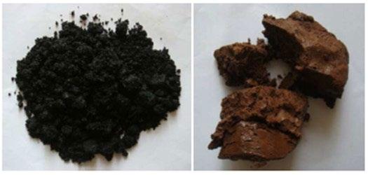
Nella seguente tabella (Tabella 1) sono riportate alcune composizioni di fanghi di decapaggio provenienti da un processo di decapaggio che impiega solfato di sodio Na2SO4 e acido fluoridrico HF con acido nitrico HNO3. La so-
luzione acida esausta è stata trattata con calce nella fase di neutralizzazione.
Tab.1 - composizioni chimiche di alcuni fanghi di decapaggio in peso % [19].
Per quanto riguarda la dimensione delle unità costituenti (particelle), al momento della formazione del fango sono più piccole ma, con il passare del tempo, i fanghi tendono a coalescere all’interno del bagno decapante generando così agglomerati massivi più grandi [20]
I fanghi elencati nella tabella di cui sopra, appaiono sotto forma di massa solida compattata. Il materiale costituente è caratterizzato da una grana fine con una dimensione delle particelle in media di circa 3.7 µ m con il 90% delle particelle di dimensioni minori di 12 µ m. La densità del “bulk” e il relativo pH equivalgono rispettivamente a 1.18 g/cm3 and 10.02 [19].
TECNICHE PER IL RECUPERO DEI METALLI
Le attività di ricerca che sono focalizzate sul recupero dei metalli dai fanghi di decapaggio si basano sulle seguenti strategie. La prima equivale alla caratterizzazione del fango in termini di contenuto dei metalli: questo è fondamentale per capire la “best practice” che può essere adottata valutando tutti gli aspetti tecnici, ambientali ed economici. É anche importante capire il frazionamento dei metalli pesanti nelle varie fasi di processo di formazione del fango per selezionare una opportuna procedura di trattamento o di recupero del metallo stesso. La seconda è relativa al controllo della sorgente, ed è la via più diretta per minimizzare a valle il quantitativo dei fanghi di decapaggio o per ottimizzarne le caratteristiche perchè incontrino i requisiti previsti dalla tecnica di recupero scelta. Una terza strategia è il riciclo di alcuni componenti dei fanghi economicamente validi che possono essere impiegati nuovamente negli impianti di produzione come materia prima [19]. Relativamente all’ultimo punto, le tecniche più ampia-
mente utilizzate per il recupero dei metalli su scala industriale sono la riduzione dei componenti del fango e l’estrazione dei metalli. Con la prima, si ri-ottiengono gli elementi nello stato di interesse attraverso processi pirometallurgici o il recupero diretto. Con la seconda, si utilizzano i processi idrometallurgici [21].
METODI PIROMETALLURGICI
I processi pirometallurgici impiegano il calore per fondere i componenti dello scarto: si procede con l’incenerimento e il “roasting” ad alta temperatura, utilizzando gas e forni ad arco specifici [22]. Molte delle metodologie di seguito elencate sono applicate nel panorama industriale:
(1) Processo INMETCO
(2) Processo STAR
(3) Impiego degli scarti di produzione come flux in AOD ed EAF

(4) RKEF
(5) Processo di separazione magnetica
Il processo INMETCO [16] è basato su tre passaggi: preparazione dei materiali, miscelazione e pellettizzazione; riduzione; fusione e lavorazione. I minerali ferrosi, i rifiuti riciclati, carbone in polvere e leganti sono miscelati insieme in pellets contenenti carbonio che sono successivamente ridotti in un forno rotativo per produrre del ferro tramite riduzione diretta che può essere direttamente caricato in forno elettrico ad arco (EAF). È importante che il fango di decapaggio non contenga un’elevata quantità di CaF2 poiché non può essere impiegato per questa tecnologia [14].
Il processo STAR è un processo di riduzione a caldo con l’utilizzo di un “coke packed bed”. Questo processo è stato sviluppato dalla Kawasaki Steel Corporation e la sua
applicazione industriale è iniziata nel 1994 per trattare in maniera flessibile vari tipi di materie prime inclusi i minerali ferrosi, cromite, polvere proveniente dal processo di produzione dell’acciaio, scorie e fanghi di decapaggio [23]-[24]. Questi sono facilmente ridotti a metalli entrando in contatto con il “coke packed bed” ad alta temperatura.
Il processo è caratterizzato da: (a) un forno a tino con un “coke packed bed”; (b) l’utilizzo di due coppie di tubiere; (c) l’utilizzo diretto di materie prime pregiate senza agglomerazioni, (d) una riduzione in forno ad alta temperatura, come mostrato in Figura 2.
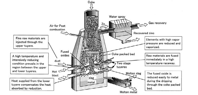
Fig.2 - processo di riduzione per il riciclo delle polveri provenienti dal processo di produzione dell’acciaio [25].
In questo processo, il secondo passaggio descritto sopra, gioca il ruolo più importante ed è efficace per la riduzione delle materie prime meno riducibili. La polvere e il fango sono miscelati insieme e stoccati in un apposito serbatoio dei residui. Ovviamente, le composizioni dei materiali di scarto scelte variano con le tipologie di prodotto colato. Un problema comune è l’asciugatura delle polveri a causa della loro ri-ossidazione spontanea. La materia prima disidratata è trasportata pneumaticamente e iniettata dalle tubiere superiori e fusa immediatamente lungo il percorso. Il metallo e la scoria prodotti sono condotti nel cuore del forno e spillati a intervalli di tempo regolari. Il metallo è fuso con una macchina di colata e viene riciclato come fonte di cromo e nichel in acciaieria. Invece, il gas ottenuto come sottoprodotto dalla lavorazione è impiegato come combustibile nelle fasi di lavoro [25].
Un’altra possibilità è quella di utilizzare gli scarti come “flux” (componente fondente) nel decarburatore ad argon e ossigeno (AOD) e nel forno ad arco elettrico (EAF). Con questo metodo, gli ossidi dei metalli che compongono i fanghi di decapaggio possono essere impiegati come materia prima per produrre l’acciaio inossidabile, mentre gli
ossidi di calcio e i fluoruri di calcio possono essere usati come agenti “fluxing” [19]. La quantità di questi ultimi per alcuni fanghi di decapaggio, rappresenta più della metà del peso totale. Tale aspetto, in aggiunta ad una bassa quantità di zolfo, è la corretta combinazione perchè vengano impiegati in questa modalità [12]. Lo stesso metodo è già applicato con successo nel riciclo della polvere proveniente dall’EAF [12]: i fanghi vengono ridotti in bricchette e asciugati per rimuovere l’ammontare di acqua totale (libera e combinata). Altre tecniche di recupero emergenti sono il forno elettrico rotativo (RKEF) che viene impiegato in un processo che adotta queste fasi operative: preasciugatura, riduzione e trattamento ad alta temperatura nel forno rotativo; poi c’è la fusione nel forno elettrico. Il prodotto ottenuto è una ferro-lega contenente Cr e Ni [12]. Anche il processo di separazione mediante riduzione magnetica rappresenta un’altra alternativa; la sua procedura prevede asciugatura, frantumazione e macinazione, miscelazione, bricchettatura, “roasting” e separazione magnetica. Per avere una buona percentuale di recupero degli elementi (Fe, Cr e Ni), la temperatura di riduzione appropriata deve essere più alta di 1325 °C [26]. La fatti-
bilità di queste due ultime tecnologie deve essere ancora ampiamente valutata, non solo tecnicamente ma anche da un punto di vista ambientale [12].
In generale, le fasi dei processi pirometallurgici sono associate a svantaggi e limitazioni dovute sia all’elevato consumo energetico che alla scarsa qualità del prodotto finale [27].
Esistono anche processi pirometallurgici in presenza di vapor d’acqua: un esempio è dato da un impianto [28] basato su processi termici (piroidrolisi) che comportano diverse reazioni chimiche. Viene impiegato un reattore ad alta temperatura in cui vengono trasferiti gli ossidi dei metalli. Questi ultimi costituiscono la fase solida dei fanghi di decapaggio, la frazione umida invece, rappresentata dai rispettivi acidi, è trasferita in fase gassosa. Nel caso di soluzioni di decapaggio a base di acido nitrico e fluoridrico, si verificano le seguenti reazioni piroidrolitiche: in primis vi è la decomposizione di una parte di acido nitrico che porta alla formazione di gas NOx [29]. Poi, a valle di una colonna di ossidazione, questi gas sono convertiti in acido nitrico. I rimanenti NO x presenti nei gas esausti devono essere eliminati mediante un trattamento catalitico (denitrificazione) da cui si forma innocuo N2 [30].
Per la rigenerazione piroidrolitica delle soluzioni esauste di decapaggio contenenti HNO3 e HF invece, vengono impiegati due principali reattori di base: uno spray roaster e un reattore a letto fluido [31]. Anche se la nanofiltrazione è applicata prima dell’intero processo, il recupero dei componenti chimici è di circa il 99% per l’acido fluoridrico HF e oltre il 90% per l’acido nitrico HNO3. Invece, il Fe, Cr e Ni sono convertiti nei rispettivi ossidi e diretti al processo di “smelting”.
METODI IDROMETALLURGICI
Nell’ultimo decennio, anche le tecnologie di recupero idrometallurgiche sono state prese in considerazione come alternative più adatte rispetto alla pirometallurgia poichè quest’ultima richiede più energia e comporta costi più alti. In confronto, l’idrometallurgia impiegata per il recupero dei metalli da scarti di produzione risulta più efficiente (è possibile regolare i livelli di impurezze nei diversi passaggi applicativi), viabile economicamente e consuma meno energia [27].
Il recupero del metallo tramite l’idrometallurgia si veri-
fica tipicamente mediante tre passaggi: dissoluzione del metallo, concentrazione, purificazione e recupero dello stesso [32]. La dissoluzione del metallo avviene attraverso metodi chimici e lisciviazione biologica. Il fluido prodotto dalla lisciviazione stessa garantisce, a seguito di processi di concentrazione e purificazione, di concentrare gli ioni metallici che sono il target di recupero e di rimuovere, se necessario, le impurezze che possono interferire con essi. Il recupero del metallo è tipicamente ottenuto mediante reazioni chimiche o applicando una differenza di potenziale. I metodi più comunemente utilizzati sono la precipitazione (anche impiegata come step di purificazione), l’elettrodeposizione in celle elettrolitiche e la riduzione mediante gas. La purificazione degli ioni metallici è fondamentale per garantire una buona percentuale di recupero alla fine del processo. Essa è basata sulle differenze nelle proprietà termodinamiche di ciascun materiale coinvolto. I metalli disciolti sono comunemente separati dal sottoprodotto usando tecniche come l’estrazione tramite solvente, lo scambio ionico, l’adsorbimento a carbone e la precipitazione [33]. Da un punto di vista industriale, le tecniche descritte sopra sono impiegate in modo combinato per strutturare un processo di recupero completo. Ciascuno di questi ne rappresenta una fase.
(1) L’estrazione liquido-liquido o con solvente è un processo comune per concentrare selettivamente i metalli. L’estrazione liquido-liquido viene eseguita usando un estrattore di tipo organico disciolto nella fase organica. La fase organica entra in contatto con la fase acquosa che contiene i metalli anch’essi disciolti o sotto forma di ioni metallici complessi. La fase acquosa e organica sono immiscibili l’una con l’altra: l’estrazione tramite solvente quindi è condotta con l’utilizzo di un miscelatore. Quest’ultimo disperde la fase organica in quella acquosa sotto forma di piccole gocce che vanno a migliorare la cinetica di estrazione.
(2) Lo scambio ionico è una forma molto comune per concentrare e purificare le soluzioni di interesse. É una tecnica nota da quasi 150 anni [10]: alcune tipologie di suolo contengono allumino-silicati che sono noti per avere capacità di scambio ionico. Oggi, argille specifiche, stratificate come minerali di tipo silicato, sono utilizzate per lo scambio ionico. Analogamente vengono utilizzate anche
le zeoliti, essendo minerali silicati porosi così come grani in resina di tipo ionico strutturati in un network polimerico poroso. All’ interno dei pori sono presenti gruppi funzionali con specifiche capacità di scambio ionico. Essi sono infatti in grado di adsorbire una grande quantità di specie disciolte. Dopo di che, le specie trattenute dai grani vengono rilasciate mediante “stripping”. Lo strippaggio avviene utilizzando un’elevata concentrazione di un componente chimico simile alle specie caricate dalla resina. (3) La precipitazione è un metodo comune per concentrare il contenuto dei metalli e aumentare il grado di purezza della soluzione. Essendo molti ioni metallici divalenti, come gli ioni di ferro, relativamente solubili a pH bassi e intermedi, si sfrutta questa differenza nelle solubilità dei componenti presenti poiché questa, in quanto funzione del pH, facilita le separazioni. La precipitazione è anche praticata attraverso una riduzione da contatto per produrre il metallo.
Di seguito alcuni esempi inerenti all’applicazione delle tecnologie menzionate sopra. Il primo esempio è dato dal processo Kawasaki. Esso è stato inizialmente sviluppato dalla Nisshin Steel Corporation. La Kawasaki Steel lo ha ulteriormente implementato e ha commissionato nel 1982 un impianto di rigenerazione su scala industriale per il loro sito di Chiba. In pratica, il processo comprende i seguenti passaggi (Tabella 2): per prima cosa, nella fase di processo (A), il Fe3+ è estratto in maniera selettiva dalla
soluzione esausta di decapaggio. Successivamente, il Fe
è sottoposto a strippaggio ed estratto nella fase organica a cui segue la formazione di un complesso nella fase acquosa che precipita sotto forma di cristalli. Questi cristalli si decompongono termicamente a una temperatura di circa 500 °C, formando ossido di ferro solido Fe2O3 e fluoruro gassoso. Quest’ultimo prodotto è rimosso tramite adsorbimento dal gas di combustione. Nella fase di processo (B), alla soluzione acida esausta impoverita di ferro (il raffinato della prima estrazione), viene aggiunto acido cloridrico HCl. Così facendo, si formano i cloruri di nichel e cromo e l’acido nitrico HNO3 viene rilasciato. Nello step successivo, l’acido fluoridrico e l’acido nitrico vengono estratti dalla soluzione risultante. Da questa fase organica, la miscela di acidi viene strippata dall’acqua e può così essere re-impiegata nel processo di decapaggio. La soluzione impoverita in acido e arricchita in sali metallici (il raffinato della seconda estrazione) viene neutralizzato: questo causa la precipitazione dell’idrossido del metallo. Gli idrossidi sono separati e ad essi viene aggiunto acido solforico. Poi, questi subiscono una conversione chimica durante la quale si generano gli ossidi dei metalli che possono anch’essi essere riutilizzati all’interno del processo. La resa del processo di estrazione del ferro è di circa 95 %, il recupero dell’acido nitrico è di circa il 95% e quello dell’acido fluoridrico del 70% [31].
Tab.2 - le fasi del processo e il relativo solvente impiegati nel processo Kawasaki [34].
Fase di processo
(A): Fe3+ estrazione → Fe3+ stripping tramite soluzione NH4HF2 → riscaldo di (NH4)2FeF6 in aria
(B): aggiunta di HCl → estrazione dell’acido → Rimozione dell’acido tramite acqua
Un altro esempio è rappresentato da un metodo sviluppato su scala di laboratorio per un’efficace separazione dell’idrossido di Nichel Ni(OH)2 attraverso un processo formato dai seguenti passaggi: come primo step c’è la precipitazione selettiva di ferro e cromo sotto forma di fluoruri, mantenendo il nichel in soluzione. Poi c’è l’idro-
Solvente
(A): 30% D2EHPA+70% n-paraffina
(B): 70% TBP+30% n-paraffina
lisi dei fluoruri solidi di ferro e cromo K2FeF5 and CrF3 mediante la reazione con l’idrossido di potassio KOH. Questa rilascia il fluoruro di potassio KF in soluzione consentendo il recupero degli idrossidi di ferro Fe(OH)3 e cromo Cr(OH)3. Dopo di che si ha la precipitazione dell’idrossido di nichel Ni(OH)2, aggiungendo KOH allo scarto liqui-
do ottenuto dalla precipitazione selettiva del ferro e del cromo. Infine si ha il recupero dell’acido, trattando le frazioni liquide provenienti dalla precipitazione del Ni(OH)2 e dell’idrolisi dei fluoruri mediante colonne a scambio ionico. Un’altra possibilità che è stata studiata è l’utilizzo di elettrodialisi mediante membrane bipolari per procedere sia al recupero che alla concentrazione dell’acido nitrico HNO3 e fluoridrico HF. Le condizioni sperimentali testate (pH: 4.1-4.2; temperatura:60-65 °C; %KF in soluzione alcalina: 14-15%) consentono di ottenere un recupero del nichel più alto del 72% con una purezza del 100% [35].
CONCLUSIONI
Lo scopo del presente articolo è di definire le tecnologie industrialmente disponibili che rendono possibile il recupero totale degli scarti di decapaggio: non solo la frazione acida ma anche quella metallica. Un altro aspetto da valutare riguarda la possibilità di miscelare tali scarti con materiali di risulta provenienti da altre fasi di processo con lo scopo di riutilizzare questo insieme di sottoprodotti all’interno dello stesso ciclo di produzione. A seguito della suddetta analisi, è possibile constatare che ad oggi sono presenti alcune valide proposte, ma non esiste un’unica tecnologia in grado di garantire un’elevata percentuale di recupero con bassi costi di installazione. Quindi, in generale, il miglior metodo di recupero può essere valutato di volta in volta a partire dalla fase di “collecting”,
caratterizzazione e classificazione del fango in termini di contenuto di metalli. Se necessario, può essere effettuato un controllo sulla sorgente per ottimizzare le caratteristiche del fango stesso e modificare il prodotto finale. Solo alla fine può essere effettuata la scelta circa la migliore tecnologia da adottare.
Nell’ambito dello studio effettuato, due filiere sono risultate promettenti in termini di recupero: L’approccio pirometallurgico e idrometallurgico.
Per quello pirometallurgico, sono richiesti bassi contenuti di zolfo e fluoro, così come di ossido di silicio e fosforo. La tradizionale pellettizzazione/sinterizzazione nel processo dell’altoforno può essere utilizzata come parziale soluzione ma sul lungo termine è necessario definire una valutazione complessiva dell’intero processo sia dal punto di vista tecnico che economico. Altre tecniche sono state analizzate ma la maggior parte è ancora allo stato di impianto pilota.
Sul lato idrometallurgico, gli approcci proposti sono più economici e garantiscono un elevato livello di purezza del prodotto recuperato derivante dal fatto che è possibile regolare le impurezze ad ogni fase di processo usando mezzi acquosi combinando acqua, ossigeno e altri reagenti chimici con o senza l’ausilio di ambiente pressurizzato. Le tecniche adottate sono l’estrazione con solvente, lo scambio ionico e la precipitazione.
BIBLIOGRAFIA
[1] A. Di Schino, ‘Manufacturing and applications of stainless steels’, Metals, 2020.
[2] C.O.A. Olsson and D. Landolt, ‘Passive films on stainless steel - Chemistry, structure and growth’, Electrochimica Acta, 2003.
[3] G. Napoli, O. D. Pietro, G. Stornelli, and A. D. Schino, ‘Effect of thermo-mechanical processes on microstructure evolution in austenitic stainless steels’, Procedia Structural Integrity, vol. 24, pp. 110–117, Jan. 2019, doi: 10.1016/j.prostr.2020.02.010.
[4] M. W. Roberts and J. M. Thoma, ‘Surface and Defect Properties of Solids’, vol. 6, 2007.
[5] Zurek J., L. N. Hierro, J. Piron-Abellan, L. Niewolak, L. Singheiser, and W. J. Quadakkers, ‘Effect of alloying additions in ferritic 9-12 %Cr steels on the temperature dependence of the steam oxidation resistance’, presented at the 6th International symposium on high temperature corrosion and protection of materials, Les Embies, 2004.
[6] G. Di Caprio, Gli acciai inossidabili. Hoepli, 2003.
[7] K. K. S. Archana Agrawal, ‘An overview of the recovery of acid from spent acidic solutions from steel and electroplating industries’, Journal of Hazardous Materials, no. 171, pp. 61–75, Jun. 2009.
[8] V. K. T. Anupam Singhal Satya Prakash, ‘Characterization of stainless steel pickling bath sludge and its solidification/stabilization’, Science Direct, pp. 1010–1015, Feb. 09, 2007.
[9] A. M. Al-Mayouf, A. K. Al Ameery, A. A. A. Al Suhybani, Brit. Corros. J, no. 36, p. 127, 2001.
[10] F. Mancia, ‘Treatment plant for continuous regeneration of stainless steels exhaust pickling solutions based on HNO3free process’.
European Commission, 2002.
[11] L.-F. Li, P. Caenen, and J.-P. Celis, ‘Effect of hydrochloric acid on pickling of hot-rolled 304 stainless steel in iron chloride-based electrolytes’, Corrosion Science, vol. 50, no. 3, pp. 804–810, Mar. 2008, doi: 10.1016/j.corsci.2007.09.006.
[12] Cong-cong, J. P. Guo De-qing Zhu, Zheng-qi, and , Xiao-ming Li, ‘Pyrometallurgical recycling of stainless steel pickling sludge: a review’, J. Iron Steel Res. Int., no. 26, pp. 547–557, May 2019.
[13] J.L. Ga´lvez, J. Dufour, and F. Lo´pez-Mateos, ‘Fluoride speciation in stainless steel pickling liquor’, ISIJ Int., vol. 46, pp. 281–286, 2006.
[14] Xiaoming Li, Shangje Wang, Junxue Zhao, Yaru Cui, and Subo Hou, ‘A review on the treatments and minimization techniques of stainless steel pickling sludge’, Advanced materials research, vol. 194–196, pp. 2072–2076, 2011.
[15] Li Xiao-ming, Xie Geng, Hojamberdiev Mirabbos, Cui Ya-ru, and Zhao jun-xue, ‘Characterization and recycling of nickel- and chromium-contained pickling sludge generated in production of stainless steel’, J.Cent.South Univ., no. 21, pp. 3241–3246, 2018.
[16] Ma P., Bjorkman B., and Lindblom B., ‘Experimental studies on solid state reduction of pickling sludge generated in the stainless steel production’, Scandinavian journal of metallurgy, vol. 34, pp. 31–40, 2005.
[17] Lindblom B. and Ma P., ‘Characterisation and reduction studies of the waste pickling sludge of stainless steel’, 1999, pp. 1493–1501.
[18] Masahiko Ito, Katsuji Fukushima, Yoshikazu Seino, Akira Yamamoto, and Yoshikazu Kawabata, ‘Characteristics and production mechanism of sulfuric acid and nitric-hydrofluoric acid pickling sludge produced in manufacture of stainless steel’, Journal of chemical engineering of Japan, vol. 31, no. 4, pp. 589–595, 1998.
[19] Li Xiao-ming, Mousa Elasyed, Zhao jun-xue, and Cui Ya-ru, ‘Recycling of sludge generated from stainless steel’, presented at the Congress on the science and technology of ironmaking.
[20] Masahiko Ito et al., ‘Development of recycling system for sludge from stainless steel nitric-hydrofluoric acid pickling process’, ISIJ Int., vol. 37, no. 4, pp. 391–398, 1997.
[21] Zhao Junxue, Zhao Zhongyu, Shi Ruimeng, Li Xiaoming, and Cui Yaru, ‘Issues Relevant to recycling of stainless-steel pickling sludge’, The minerals, metals & materials society, 2018.
[22] M. Kaya, ‘Recovery of metals and nonmetals from electronic waste by physical and chemical recycling processes’, Waste management, pp. 64–90, 2016.
[23] Y. Kishimoto, K. Taoka, and S. Takeuchi, ‘Kawasaki steel tech. rep. N°37, 51-58’. 1997.
[24] T. Uetani and N. Bessho, ‘Kawasaki steel tech. Rep. N°44, 43-51’. 2001.
[25] Y. Hara, N. Ishiwata, H. Itaya, and T. Matsumoto, ‘Smelting reduction process with a coke packed bed for steelmaking dust recycling’, ISIJ Int., vol. 40, no. 3, pp. 231–237, 2000.
[26] X.L. Liu, J. Zhang, Q. Xiao, and Q.J. Li, EPD Congress. John Wiley & Sons., 2014.
[27] Viraj Gunarathne, Anushka Upamali Rajapaksha, Meththika Vithanage, and Daniel S. Alessi, ‘Hydrometallurgical processes for heavy metals recovery from industrial sludges’, Critical reviews in enviromental science and technology, Dec. 2020.
[28] F. Baerhold, J. Starcevic, and K. Reichert, ‘Reduction of nitrates in stainless steel pickling’, Millenium Steel, pp. 238–239, 2006.
[29] W. Wukovits, W. Kramer, A. Lebl, M. Harasek, and A. Friedl, ‘Simulation and optimization of the reactive absorption of HF/HNO3 during pickling acid regenration’, presented at the European symposium on computer aided process engineering.
[30] W.F. Kladnig, ‘New development of acid regeneration in steel pickling plants’, Journal of iron and steel research, International, vol. 15, no. 4, pp. 01–06, 2008.
[31] F. Rogener, Yu. A. Lednova, and A.V. Lednova, ‘Sustainable stainless steel- A review on acid regeneration systems for application in continuous pickling lines’, ТЕХНОЛОГИИ ОБРАБОТКИ МАТЕРИАЛОВ., 2019.
[32] C.k. Gupta, Chemical Metallurgy: principles and practice. John Wiley & Sons, 2006.
[33] Michael L. Free, Hydrometallurgy: fundamentals and applications, John Wiley&Sons. Hoboken, New Jersey, 2013.
[34] T. Watanabe, M. Hoshino, and K. Uchino, ‘A new acid and iron recovery process in stainless steel annealing and pickling line, N° 14, 72-82’. 1986.
[35] J. Hermoso, J. Dufour, J.L. Ga´lvez, C. Negro, and F. Lopez-Mateos, ‘Nickel hydroxide recovery from stainless steel pickling liquors by selective precipitation’, Ind. Eng. Chem. Res., vol. 44, pp. 5750–5756, 2005.
ALL'INDICE >
Industrial techniques for recovery of stainless steel pickling sludge: a review
edited by: C. Tirasso, C. Rocchi, K. BrunelliIn stainless steel, the pickling process is a fundamental step for removing from material surface the superficial oxides scale that forms during the previous annealing treatments. Pickling solutions must be dumped because their efficiency decreases with increasing content of dissolved metal in the bath. Therefore, this productive step is associated with the generation of wastes whose state of aggregation can be solid, liquid or gaseous. The impact of these solutions on the environment is notable due to their complex and hazardous nature.
In the last years, the research community developed new approaches to recover metals and/or acids from the spent industrial solutions in order to promote both a sustainable production and an economical saving. Different physicalchemical methods aimed at recovery are applied. In general, they can be divided in two groups: the methods enabling only acid recovery and the methods allowing both metal and acid recovery.
In this paper, the following topics will be described: the formation of the pickling sludges, and their chemical physical properties; the actual techniques employed for the metals recovery from sludges.
INTRODUCTION
Stainless steels are employed in different applications: chemical and pharmaceutical sector, food industry, construction field, furniture and for every use that requires a high corrosion resistance and specific aesthetic appeal [1].
The Chromium present in stainless steel provides for the formation of an adherent and thin passive layer that protects material surface. It is generally formed by Cr2O3 with a thickness around 2 nm [2]. The existing passive layer can be physically damaged by the steps of heating and cooling that characterize the stainless steel annealing treatments. These ones are required to recover the work hardened material [3] and to guarantee an adequate microstructure and mechanical properties. During these processes, one or more mixed oxide layers, defined as “oxide scale”, are formed and thickness doesn’t exceed 500-600 nm [4]. Their constituent elements depend on the examined stainless steel and on their diffusion through the steel matrix influenced by the annealing conditions (time, temperature and atmosphere). For example, steels with a Cr content of over 13% have a scale formed by Cr2O3, (Cr,Fe)2O3 or Cr rich (Cr, Fe, Mn) 3O4 with an outer layer of Fe2O3 [5].
Therefore, after annealing, it is necessary to remove the oxide scale in order to ensure a uniform and homoge-
Chiara Tirasso, Claudia Rocchi
Acciai Speciali Terni (AST) chiara.tirasso@acciaiterni.it claudia.rocchi@acciaiterni.it
Katya Brunelli
Università di Padova katya.brunelli@unipd.it
neous surface. The removal of oxide scale takes place in two different steps (mechanical pickling and chemical pickling), depending on the material surface. After the hot rolling and the subsequent annealing process, stainless steel is pickled both in a mechanical and in a chemical way. These passages are sequential. Instead, after the cold rolling and the following annealing process, material is cleaned only with the chemical pickling [6].
The mechanical pickling acts on the superficial oxide layers. The pickling performed through chemical solutions, instead, works on the stainless steel matrix, in direct contact with the Cr-depleted layer just below the surface (which is generated in the previous annealing phase). The chemical pickling is carried out with concentrated acid solutions that are progressively consumed with the formation of subproducts. This means a significant decreasing of pickling rate.
Because of that, pickling solutions need constant refresh: the aim is to guarantee the same efficiency in every process instant. From another point of view, significant amounts of wastes are produced as salts, metal oxide particles and acid spent solutions. They are highly corrosive and polluting if released in to the environment also at low concentration [7].
Industrial applications developed to make the pickling process more eco-sustainable are mainly focused on the recovery of acids from the waste pickling liquor. Instead, the solid waste fraction, defined as “sludges” continues to be categorized as a waste with few possibilities of recycling although the containing of valuable metals and salts.
This is caused by the difficulty of selecting a “complete” regeneration method because there are different elements in different states of oxidation. In addition, in the “sludges” there are also other components as inhibitors, surfactants and stabilizers that make an efficient recovery difficult. For this reason, generally, through the neutralization technique, they are converted to metal salts and properly stored in landfills disposed by the industrial site, even if they could be a resource as they contain cost-
ly elements that could be reused into the stainless steel production cycle.
FORMATION AND CHARACTERIZATION OF PICKLING SLUDGES
Analyzing the industrial pickling process of stainless steels, there are two different steps that generate sludges from which useful components can be obtained [8]:
(3) The process within pickling tanks with the mixed acid solutions. They produce metals and metal oxides mainly, coming from the precipitation of metal scale, rust and dust that affect the material.
(4) The process in the effluent treatment plants where two elements are treated: the spent acid pickling liquor (if acid is not recycled through specific recovery techniques) and the pickling wastewater. They produce metal hydroxides and gypsum (CaSO4· 2H2O).
In the first industrial step the chemical pickling generally works on stainless steels through aggressive mixed acid solutions formed by nitric acid HNO3 and hydrofluoric acid HF [9]. Some industries use an ecologic solution which is “nitric free”: a mixture of sulfuric acid H2SO4, hydrofluoric acid HF and hydrogen peroxide H2O2 [10].
In the last years, also hydrochloric acid HCl, as a replacement for sulfuric acid H2SO4, has been suggested because it guarantees a better surface quality of the treated material [11]. Also for the chemical descaling phase, which occurs before the chemical pickling, chemical reagents are used as sodium sulfate Na2SO4 or sulfuric acid H2SO4 [12], [13] that generate solid wastes as well.
Solid components that result from the chemical reaction between acids and the alloying elements (such as Fe, Cr and Ni) of the stainless steel matrix must be removed from the pickling bath. They are conveyed with the effluents (waste pickling liquor and acid wastewater) coming from the second industrial step highlighted above. They are generally treated by neutralization, chemical reduction and precipitation process respectively. The reduction step is necessary when the chemical reaction between the acidic solutions and the material generates ions Cr6+. Because of its po-
tential danger, it must be reduced to an harmless chemical component (Cr3+) in order to proceed with the precipitation step using components as lime [14]. The sediments
formed are also dehydrated and filter-pressed to obtain sludge cakes (Figure 1).
A lot of studies were conducted in order to characterize them both from a chemical and a physical point of view [16] [17] [18].
In general, sludges have colors that vary from yellow to dark brown depending on their composition and free water content [12]. They contain chemical components based on iron, chromium, nickel, calcium, fluorine, sulphur and oxygen. The first three ones exist as amorphous phases, while the other components, such as calcium fluoride CaF2, calcium sulphate CaSO4, chromium oxide Cr2O3 and spinel phase of ferrous chromic oxide FeCr2O4, exist as crystalline phase [19]. These last two kind of oxides are difficult to dissolve in to the acid mix of nitric-hydrofluo-
[14].
ric acid. This fact means that the scale on the surface of stainless steel exfoliates in the pickling solution and accumulates as sludges [20]. Also tiny particles of CaSO 4, CrF2 and CaCO3 are present [15]. Other components such as CaF2 and CaSO4 don’t exist in to the stainless steel’s scale but they are formed during respectively the neutralization and reduction process.
In the table below (Table 1.) some compositions of pickling sludges samples are listed: they come from an industrial pickling process having sodium sulphate Na2SO4 and hydrofluoric acid HF with nitric acid HNO3. The waste acid was treated with lime for the neutralization step.
Tab.1 - major chemical composition of some pickling sludges in %wt [19].

As regards their particle size, at the formation they are small but, with the passage of time, sludges tend to cohere with each other in to the acid solutions and grow in bigger agglomerate masses [20].
The sludges listed above, under the form of filtered cakes, present a fine-grained material with a mean particle size of about 3.7 µ m, 90% of the particles are less than 12 µ m. The bulk density and pH pickling sludge is 1.18 g/cm 3 and 10.02 respectively [19].

TECHNIQUES FOR METALS RECOVERY
The research activities focused on metals recovery from pickling sludges are based on the following approaches. The first is the characterization of sludge in terms of metals content: this is fundamental to understand the best practice that must be adopted in terms of technical, environmental and economical solutions. It is also important to understand the fractionation of heavy metals in to the different phases of sludge to select an appropriate treat-
ment procedure or metal recovery approach.
The second is the source control, and it is the most direct way to minimize the pickling sludge or to optimize its characteristics in order to meet the requirement for the chosen recovery technique. A third approach is the recycling of some valuable components, that can be added back to the stainless steel plant as raw materials [19].
In reference to the last point, the most widely used techniques to recover metals in industrial-scale applications are the reduction, to get back valuable elements using pyrometallurgical processes or the direct recycling and extraction of metals using hydrometallurgical processes [21].
PYROMETALLURGICAL METHODS
Pyrometallurgical processes use heat to smelt the constituents of waste: it consists of incineration and high-temperature roasting, using selective gases or arc furnaces [22]. A lot of these methods are used in the industrial scene:
(1) The INMETCO process
(2) The STAR process
(3) Utilization of wastes as flux in AOD and EAF
(4) RKEF
(5)
Reduction magnetic separation process
The INMETCO process [16] is based on three steps: feed preparation, blending and pelletizing; reduction; smelting and casting. Iron ores, recycling wastes, pulverized coal and binder are mixed and made into carbon-containing pellets which are subsequently reduced in a rotary hearth furnace to produce hot, metallized direct reduction iron (DRI) that can be directly charged in the EAF for smelting. It is important to say that pickling sludge with high CaF2 is excluded in this method [14].
The STAR process is a smelting reduction process with a coke packed bed. This process was developed by Japan’s Kawasaki Steel Corporation and started its industrial application in 1994 to flexibly treat various types of raw materials including iron ores, chromite ore, steelmaking dust, slag and pickling sludge [23]-[24]. They are easily reduced to metal as they drip through the high temperature coke-packed bed. The process is characterized by: (a) a shaft furnace with a coke packed bed; (b) the use of two-stage tuyeres; (c) direct use of fine raw materials without agglomeration; (d) a simple smelting reduction furnace, as shown in Figure 2.
Fig.2 - the smelting reduction process for steelmaking dust recycling [25]

In this process, the second step described above, plays the most important role and is effective for the smelting reduction of less reducible raw materials. The dust and the sludge are mixed and stored in a slurry tank. The compositions of waste materials fluctuate according to the kinds of product at the steelmaking shop. One common
problem is the drying of the dust because of its self-oxidation and fire. Rapid drying by a spray dryer is used to protect the slurry from oxidation. Dried raw material is transported pneumatically and injected from the upper tuyeres and is fused immediately in the raceway. Produced metal and slag are held in the hearth and tapped at a
constant interval of time. The metal is cast with a casting machine and recycled to the steelmaking shop as a source of chromium and nickel. The by-product gas is used as a fuel in the works [25].
Another possibility is the utilization of wastes as flux in argon-oxygen decarburization converter (AOD) and EAF. By this method, the metal oxides which exist in the pickling sludge can be used as raw materials to produce stainless steel, while the calcium oxides and calcium fluoride can be used as fluxing agents [19]. Their quantity, for some pickling sludges, represents more than half of the total weight. This aspect, in addition with a low quantity of S, is the right combination to use them in this way [12]. The same way is already successfully used to recycle EAF dust [12]: sludges are made in briquettes and dried to remove the total amount of water (free and combined). Others emerging recycling techniques are the RKEF (Rotary kiln electric furnace) process which adopts these operational steps: pre-drying, reduction and roasting in a rotary kiln; then there is the smelting in the electric furnace. The output is a ferroalloy containing Cr and Ni [12]. Also the reductionmagnetic separation process represents another alternative; its procedure includes drying, crushing and grinding, mixing, briquetting, gas-based reduction roasting and magnetic separation. To have good percentage of element recovery (Fe, Cr and Ni), the appropriate reduction temperature is higher than 1325 °C [26]. The feasibility of these last two techniques have still to be comprehensively assessed, not only technically but also from environmental compatibility point of view [12]. In general, the pyrometallurgical processing steps are associated with disadvantages and limitations owing to either high energy consumption or poor end-product quality [27].
There are also pyrometallurgical processes in presence of water vapor at the gaseous state: an example is given from an installed plant [28] based on thermal processes (pyrohydrolysis) at which several chemical reactions take place. There is a reactor at high temperature in which solid metal oxides are transferred. These ones form the solid phase of the pickling sludge, the humid fraction, represented by the respective acids instead, is transferred to the gaseous phase.
In the case of pickling solutions based on nitric-fluori-
dric acid mix, with the pyrohydrolytic reactions, there is the decomposition of part of the nitric acid leading to the formation of NO x gases [29]. In a downstream oxidation column these gases are converted into HNO 3. However, remaining NOx in the exhaust gas must be eliminated by a catalytic treatment (denitrification) which results in the formation of harmless N2 [30]. For the pyrohydrolytic regeneration of spent pickling solutions containing HNO3 and HF, two basic reactor principles are applied: spray roaster and fluidized bed reactor [31]. If also nanofiltration is applied before the entire process, the recovery of chemical components is about 99% for hydrofluoric acid HF and up to 90% for nitric acid HNO3. Instead, Fe, Cr and Ni are converted in metal oxides and directed to the smelting process.
HYDROMETALLURGICAL METHODS
During the past decade, also hydrometallurgical recovery has been considered as one of the most suitable alternatives to pyrometallurgy as the latter requires more energy and incurs higher costs. In comparison, hydrometallurgy is the most efficient, economically viable method for recovering metals from wastes as it regulates the levels of impurities at different stages and consumes less energy [27].
Hydrometallurgical metal recovery is typically performed in three main stages: metal dissolution, concentration, purification and metal recovery [32]. Metal dissolution takes place through chemical and bioleaching approaches. The leaching liquor resulting from this step is able, by concentration and purification processes, to concentrate metal ions that are the target of recovering and to remove, if necessary, impurities that can interfere with them. Then there is the metal recovery that typically is obtained by chemical reactions or by a voltage application. The most common methods applied are precipitation (also used in the purification step), electrodeposition in electrolytic cells and gaseous reduction. Purification of metal ions is fundamental to guarantee a good percentage of recovery at the end of the process. It is based on differences in thermodynamic properties of each metal involved. Dissolved metals are commonly separated from the byproduct using techniques like solvent extraction, ion exchange, carbon adsorption and
precipitation [33]. From an industrial point of view, the techniques described above are used in a combined way to structure a complete recovery process. Each of them represents a phase in the recycle of sludges.
(1) Liquid–liquid or solvent extraction is a common process for selectively concentrating metals. Liquid–liquid extraction is performed using an organic extractant that is dissolved in an organic phase. The organic phase is allowed to contact an aqueous phase containing the dissolved metal or metal ion complex. The aqueous and organic phases are immiscible in each other. Solvent extraction is carried out using a mixer. The mixer disperses the organic phase in the aqueous phase as small droplets. Small droplets enhance the extraction kinetics.
(2) Ion exchange is a very common form of solution concentration and purification.
It has been known for almost 150 years [10]: some soils containing alumino-silicates are known to have ion-exchange capabilities. Today, specific clays, which are layered silicate minerals, are used for ion exchange. Zeolites, which are porous silicate minerals, are also used. Porous resin beads are also used for ion exchange. Ion resin beads are usually made of a porous polymeric network. Functional groups with specific ion-exchange capability are placed inside pores. The resulting porous beads are capable of loading a large quantity of dissolved species. After adsorption occurs, the beads are stripped of the loaded species. Stripping is accomplished using a high concentration of similarly charged species.
(3) Precipitation is a common method for concentrating metal content and purifying solutions. Many divalent metal ions, such as ferrous ions, are relatively soluble at low and intermediate pH levels. This difference in solubilities
as a function of pH facilitates separations. Precipitation is also practiced through contact reduction to produce metal.
A couple of examples summarizes the application of the above mentioned technologies. The first example is given by the Kawasaki process. It was initially invented by Nisshin Steel Corporation. Kawasaki Steel developed it further and in 1982 they commissioned an industrial- size regeneration plant at their Chiba site. Basically, the process comprises the following stages (Table 2): at first, in the process phase (A), Fe3+ is selectively extracted from the spent pickling acid. Subsequently, Fe3+ is stripped and extracted in the organic phase, forming a complex in the aqueous phase, which precipitates as crystals. These crystals are thermally decomposed at about 500°C and solid Fe2O3 and gaseous fluoride are formed. The last product is removed from the flue gas by absorption. In the process phase (B), the iron depleted spent acid (raffinate of the 1st extraction) is mixed with hydrcloric acid HCl. Thus, nickel and chromium chloride is formed and nitric acid HNO3 is released. In a next step, hydrofluoric acid HF and nitric acid HNO3 are extracted from the resulting solution. From this organic phase, the mixed acids are stripped by water and can be recycled back to the pickling line. The acid depleted, metal salt enriched solution (raffinate of the 2nd extraction) is neutralized: this causes metal hydroxide precipitation. The hydroxides are separated and mixed with sulfuric acid. Then, they undergo a chemical conversion, during which mixed metal oxides are generated that can be re-used. lron extraction yield of the process was about 95%, nitric acid recovery was about 95% and hydrofluoric acid recovery was about 70% [31].
Tab.2 -process steps and solvent employed in the Kawasaki process [34].
Process step
(A): Fe3+ extraction → Fe3+ stripping by NH4HF2 solution
Heating of (NH4)2FeF6 in air
(B): Addition of HCl → Acid extraction → Acid stripping by water
Solvent
(A): 30% D2EHPA+70% n-paraffin
(B): 70% TBP+30% n-paraffin
Another example is represented by a method developed on laboratory scale for the effective separation of nickel hydroxide recovery Ni(OH)2 through a process formed by general stages: as first step there is the selective precipitation of iron and chromium as fluorides, keeping nickel in solution. Then there is the hydrolysis of iron and chromium solid fluorides K2FeF5 and CrF3 by reaction with concentrated potassium hydroxide KOH. It releases potassium fluoride KF to solution and recovers iron and chromium as hydroxides Fe(OH)3 and Cr(OH)3. After that there is the nickel hydroxide precipitation Ni(OH)2, by adding KOH to the liquid effluent from selective precipitation of iron and chromium. In the end the acid recovery, treating final effluents from Ni(OH)2 precipitation and fluorides hydrolysis by means of ion exchange columns. Another studied possibility is the utilization of bipolar membrane electrodialysis in order to recover and concentrate nitric acid HNO3 and hydrofluoric acid HF. The experimental conditions tested (pH: 4.1-4.2; temperature:60-65 °C; %KF in alkali solution: 14-15%) allowed to obtain a nickel recovery higher than 72% with a purity of 100% [35].
CONCLUSIONS
The aim of the present paper is the definition of industrially available techniques that make the total recovery of pickling sludge possible: not only the acid fraction but also the metal one. Another aspect to evaluate is the possibility of mixing this waste with other industrial resulting materials with the aim to reuse the byproduct within the
same production cycle. After the present review, it is possible to state that up to date there are a lot of valid proposals, but there isn’t a unique technique able to guarantee a high percentage of recovery with low installation cost. So, in general, the best recycling method can be evaluated time after time starting from the collection, the characterization and the classification of sludge in terms of metals content. If necessary, a source control can be employed to optimize the sludge characteristics and modify the end product. At the final stage, the choice of the best technique can be performed. Two promising recycling branches have been highlighted in the present study for this sector: pyrometallurgical and hydrometallurgical approaches.
For the pyrometallurgical one, a low content of S and F are required and also of SiO2 and P. The traditional pelletizing/sintering-blast furnace process can be used as a partial solution, but long-term and overall assessment is necessary to define it for the entire process. Other techniques were analyzed but most of them are still at the stage of pilot plant process.
On the hydrometallurgical side, the approaches proposed are more economic, and guarantee a high level of purity of the recovered product due to the fact that is possible to regulate the impurities at every process stage using aqueous media by combining water, oxygen, and other chemical reagents with or without the use of a pressurized environment. The techniques adopted are solvent extraction, ion exchange and precipitation.
BIBLIOGRAFY
[1] A. Di Schino, ‘Manufacturing and applications of stainless steels’, Metals, 2020.
[2] C.O.A. Olsson and D. Landolt, ‘Passive films on stainless steel - Chemistry, structure and growth’, Electrochimica Acta, 2003.
[3] G. Napoli, O. D. Pietro, G. Stornelli, and A. D. Schino, ‘Effect of thermo-mechanical processes on microstructure evolution in austenitic stainless steels’, Procedia Structural Integrity, vol. 24, pp. 110–117, Jan. 2019, doi: 10.1016/j.prostr.2020.02.010.
[4] M. W. Roberts and J. M. Thoma, ‘Surface and Defect Properties of Solids’, vol. 6, 2007.
[5] Zurek J., L. N. Hierro, J. Piron-Abellan, L. Niewolak, L. Singheiser, and W. J. Quadakkers, ‘Effect of alloying additions in ferritic 9-12 %Cr steels on the temperature dependence of the steam oxidation resistance’, presented at the 6th International symposium on high temperature corrosion and protection of materials, Les Embies, 2004.
[6] G. Di Caprio, Gli acciai inossidabili. Hoepli, 2003.
[7] K. K. S. Archana Agrawal, ‘An overview of the recovery of acid from spent acidic solutions from steel and electroplating industries’, Journal of Hazardous Materials, no. 171, pp. 61–75, Jun. 2009.
[8] V. K. T. Anupam Singhal Satya Prakash, ‘Characterization of stainless steel pickling bath sludge and its solidification/stabilization’, Science Direct, pp. 1010–1015, Feb. 09, 2007.
[9] A. M. Al-Mayouf, A. K. Al Ameery, A. A. A. Al Suhybani, Brit. Corros. J, no. 36, p. 127, 2001.
[10] F. Mancia, ‘Treatment plant for continuous regeneration of stainless steels exhaust pickling solutions based on HNO3free process’.
European Commission, 2002.
[11] L.-F. Li, P. Caenen, and J.-P. Celis, ‘Effect of hydrochloric acid on pickling of hot-rolled 304 stainless steel in iron chloride-based electrolytes’, Corrosion Science, vol. 50, no. 3, pp. 804–810, Mar. 2008, doi: 10.1016/j.corsci.2007.09.006.
[12] Cong-cong, J. P. Guo De-qing Zhu, Zheng-qi, and , Xiao-ming Li, ‘Pyrometallurgical recycling of stainless steel pickling sludge: a review’, J. Iron Steel Res. Int., no. 26, pp. 547–557, May 2019.
[13] J.L. Ga´lvez, J. Dufour, and F. Lo´pez-Mateos, ‘Fluoride speciation in stainless steel pickling liquor’, ISIJ Int., vol. 46, pp. 281–286, 2006.
[14] Xiaoming Li, Shangje Wang, Junxue Zhao, Yaru Cui, and Subo Hou, ‘A review on the treatments and minimization techniques of stainless steel pickling sludge’, Advanced materials research, vol. 194–196, pp. 2072–2076, 2011.
[15] Li Xiao-ming, Xie Geng, Hojamberdiev Mirabbos, Cui Ya-ru, and Zhao jun-xue, ‘Characterization and recycling of nickel- and chromium-contained pickling sludge generated in production of stainless steel’, J.Cent.South Univ., no. 21, pp. 3241–3246, 2018.
[16] Ma P., Bjorkman B., and Lindblom B., ‘Experimental studies on solid state reduction of pickling sludge generated in the stainless steel production’, Scandinavian journal of metallurgy, vol. 34, pp. 31–40, 2005.
[17] Lindblom B. and Ma P., ‘Characterisation and reduction studies of the waste pickling sludge of stainless steel’, 1999, pp. 1493–1501.
[18] Masahiko Ito, Katsuji Fukushima, Yoshikazu Seino, Akira Yamamoto, and Yoshikazu Kawabata, ‘Characteristics and production mechanism of sulfuric acid and nitric-hydrofluoric acid pickling sludge produced in manufacture of stainless steel’, Journal of chemical engineering of Japan, vol. 31, no. 4, pp. 589–595, 1998.
[19] Li Xiao-ming, Mousa Elasyed, Zhao jun-xue, and Cui Ya-ru, ‘Recycling of sludge generated from stainless steel’, presented at the Congress on the science and technology of ironmaking.
[20] Masahiko Ito et al., ‘Development of recycling system for sludge from stainless steel nitric-hydrofluoric acid pickling process’, ISIJ Int., vol. 37, no. 4, pp. 391–398, 1997.
[21] Zhao Junxue, Zhao Zhongyu, Shi Ruimeng, Li Xiaoming, and Cui Yaru, ‘Issues Relevant to recycling of stainless-steel pickling sludge’, The minerals, metals & materials society, 2018.
[22] M. Kaya, ‘Recovery of metals and nonmetals from electronic waste by physical and chemical recycling processes’, Waste management, pp. 64–90, 2016.
[23] Y. Kishimoto, K. Taoka, and S. Takeuchi, ‘Kawasaki steel tech. rep. N°37, 51-58’. 1997.
[24] T. Uetani and N. Bessho, ‘Kawasaki steel tech. Rep. N°44, 43-51’. 2001.
[25] Y. Hara, N. Ishiwata, H. Itaya, and T. Matsumoto, ‘Smelting reduction process with a coke packed bed for steelmaking dust recycling’, ISIJ Int., vol. 40, no. 3, pp. 231–237, 2000.
[26] X.L. Liu, J. Zhang, Q. Xiao, and Q.J. Li, EPD Congress. John Wiley & Sons., 2014.
[27] Viraj Gunarathne, Anushka Upamali Rajapaksha, Meththika Vithanage, and Daniel S. Alessi, ‘Hydrometallurgical processes for heavy metals recovery from industrial sludges’, Critical reviews in enviromental science and technology, Dec. 2020.
[28] F. Baerhold, J. Starcevic, and K. Reichert, ‘Reduction of nitrates in stainless steel pickling’, Millenium Steel, pp. 238–239, 2006.
[29] W. Wukovits, W. Kramer, A. Lebl, M. Harasek, and A. Friedl, ‘Simulation and optimization of the reactive absorption of HF/HNO3 during pickling acid regenration’, presented at the European symposium on computer aided process engineering.
[30] W.F. Kladnig, ‘New development of acid regeneration in steel pickling plants’, Journal of iron and steel research, International, vol. 15, no. 4, pp. 01–06, 2008.
[31] F. Rogener, Yu. A. Lednova, and A.V. Lednova, ‘Sustainable stainless steel- A review on acid regeneration systems for application in continuous pickling lines’, ТЕХНОЛОГИИ ОБРАБОТКИ МАТЕРИАЛОВ., 2019.
[32] C.k. Gupta, Chemical Metallurgy: principles and practice. John Wiley & Sons, 2006.
[33] Michael L. Free, Hydrometallurgy: fundamentals and applications, John Wiley&Sons. Hoboken, New Jersey, 2013.
[34] T. Watanabe, M. Hoshino, and K. Uchino, ‘A new acid and iron recovery process in stainless steel annealing and pickling line, N° 14, 72-82’. 1986.
[35] J. Hermoso, J. Dufour, J.L. Ga´lvez, C. Negro, and F. Lopez-Mateos, ‘Nickel hydroxide recovery from stainless steel pickling liquors by selective precipitation’, Ind. Eng. Chem. Res., vol. 44, pp. 5750–5756, 2005.
TORNA ALL'INDICE >
MEDAGLIA CAVALLARO AL PROF. LUCIANO LAZZARI
La prestigiosa medaglia Cavallaro è stata assegnata al Prof. Luciano Lazzari dalla Federazione Europea di Corrosione EFC durante il congresso EUROCORR 2022 a Berlino. La medaglia d’oro, istituita dall’Università di Ferrara nel 1965, è assegnata ogni due anni a uno/a scienziato/a che si è particolarmente distinto/a per la sua attività e ricerca nel campo della corrosione. La medaglia Cavallaro in passato è stata assegnata a ricercatori di altissimo livello quali Evans (1971), Pourbaix (1975), Hoar (1977), Parkins (1985), Smialowska (1998) e molti altri, tra i quali anche gli italiani: Giuseppe Bianchi (1965), Giordano Trabanelli (1983), Francesco Mazza (1995), Fabrizio Zucchi (2020).
Luciano Lazzari è stato professore di Scienza e Tecnologia dei Materiali al Politecnico di Milano, Dipartimento di Chimica Materiali e Ingegneria Chimica Giulio Natta dal 1998 al 2016. Dal 1978 al 1986 ha svolto attività di ingegneria presso AGIP Spa (ora ENI SpA) dove è stato responsabile del Dipartimento di Corrosione e Materiali. Nel 1988 ha fondato Cescor, prima come Studio Associato e dal 1994 Cescor Srl della quale è oggi presidente. Luciano Lazzari ha svolto una regolare e intensa attività di pubblicazione: tra i libri è importante ricordare “Protezione Catodica” scritto con Pietro Pedeferri (prima edizione del 1980), e la versione inglese del libro di Pietro Pedeferri “Corrosion science and engineering” del quale Luciano Lazzari ha curato l’edizione insieme a MariaPia Pedeferri nel 2018. La candidatura del Prof. Luciano Lazzari è stata proposta dall’Associazione Italiana di Metallurgia e dall’Associazione per la Protezione dalle Corrosioni Elettrolitiche (APCE). Luciano Lazzari è stato selezionato per i suoi numerosi e brillanti contributi nei seguenti campi: protezione catodica di strutture metalliche interrate o immerse, corrosione da interferenza da corrente continua e alternata, corrosione sotto sforzo,
CAVALLARO MEDAL TO PROF. LUCIANO LAZZARI
The prestigious Cavallaro medal was awarded to Prof. Luciano Lazzari by the European Federation of Corrosion (EFC) during the congress EUROCORR 2022 in Berlin. The gold medal, instituted by the University of Ferrara in 1965, is awarded every two years to a scientist who is particularly distinguished by his/her activity and research in the corrosion field. In the past, the Cavallaro medal was awarded to prestigious researchers like Evans (1971), Pourbaix (1975), Hoar (1977), Parkins (1985), Smialowska (1998) and many others, among these Italians researchers: Giuseppe Bianchi (1965), Giordano Trabanelli (1983), Francesco Mazza (1995), Fabrizio Zucchi (2020).
Luciano Lazzari has been professor of Science and Technology of Materials at the Politecnico di Milano, Dipartimento di Chimica Materiali e Ingegneria Chimica Giulio Natta from 1998 to 2016. From 1978 to 1986 he worked at AGIP Spa, where he was responsible of the Materials and Corrosion Department. In 1988 he founded Cescor as a professional association and since 1994 as a company (Cescor Srl) of which today he is president. His impact on both research and industrial applications is reflected in his large scientific publication record, patents and books. Among these, it is important to mention “Cathodic Protection” (1st edition 1980) in cooperation with Pietro Pedeferri and “Corrosion of science and Engineering” edited by Luciano Lazzari and MariaPia Pedeferri in 2018.
The nomination of Prof. Luciano Lazzari was proposed by Associazione Italiana di Metallurgia and Associazione per la Protezione dalle Corrosioni Elettrolitiche (APCE). Luciano Lazzari was selected due to his numerous and insightful contributions to the fields of: cathodic protection of metallic structures buried or immersed, corrosion by DC and AC interference, stress corrosion cracking, hydrogen embrittlement, reinforced concrete
infragilimento da idrogeno, durabilità di strutture in calcestruzzo armato, modelli ingegneristici di previsione della velocità di corrosione, dell’innesco della corrosione localizzata, della velocità di propagazione delle cricche di corrosione sotto sforzo.
In seguito al conferimento della medaglia Cavallaro il Professore ha tenuto una conferenza plenaria dal titolo “Engineering tools for corrosion”, titolo che richiama il libro pubblicato nel 2017 nella collana della federazione europea di corrosione (EFC) e che rappresenta un compendio del suo approccio ingegneristico alla corrosione. Il prof. Lazzari nel suo intervento ha anche ricordato i suoi maestri: Giuseppe Bianchi, Dany Sinigaglia, Bruno Mazza e Pietro Pedeferri.
structuresdurability,engineeringtoolsfortheprediction of corrosion rate, pitting corrosion initiation, stress corrosion crack propagation rate.
After the awarding of the medal, the Professor held the plenary lecture “Engineering Tools for Corrosion”, whose title recall his book, published in 2017 in the European Federation of Corrosion series, that represent a summary of his “engineering approach to corrosion”. Prof. Lazzari during his conference also recalled his mentors: Giuseppe Bianchi, Dany Sinigaglia, Bruno Mazza and Pietro Pedeferri.
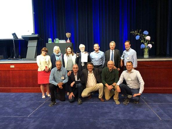
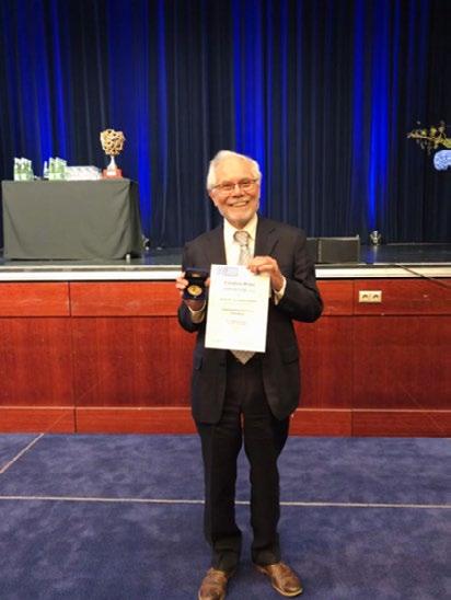
INNOVATIONS IN FRACTURE PREDICTION AND IMPACT RESISTANCE IN HIGH-STRENGTH STEELS TO STEP UP PRODUCTION EFFICIENCY IN SECTORS INCLUDING THE AUTOMOTIVE INDUSTRY
• The ToughSteel project has drawn up a database and an industry user guide which compile existing information on fracture toughness values of sheet steels and new methods for evaluating this property, respectively.

• The aim is to optimise materials selection, prevent production losses and shorten time to market for highperformance metal components which are used in several sectors such as the automotive industry.
• It is estimated that rolling out these new methodologies will cut production losses by 25% and greenhouse gas emissions by 20% through the use of lightweight materials.
The European ToughSteel project has drawn up a database and an industrial guide containing existing information on fracture toughness of sheet metals and new evaluation methods drawing on research conducted in various projects and investigations in this field. The idea is to unlock the use of fracture toughness as a tool for predicting cracks and impact resistance in high-strength steels.
The open access online database compiles fracture toughness values for various metal alloys, especially high-strength steels, to help steel producers, product design engineers, sheet metal fabricators and original equipment manufacturers (OEMs) to position their products compared to existing ones and fast-track the design of new alloys and performanceoptimised parts by anticipating forming problems. The industrial guide features application examples and information about how to use fracture toughness evaluation methods for sheet metal.
The initiatives coming under the ToughSteel project seek to “optimise materials selection, prevent production losses and shorten time to market for sheet metal products in sectors such as the automotive industry,” says David Frómeta, coordinator of the project and a researcher in the Eurecat technology centre’s Metallic and Ceramic Materials Unit. Fracture toughness “is an excellent indicator of the sheet metal’s impact resistance and whether it can be transformed in high-volume production processes without defects as has recently been shown in various scientific publications and showcased at international conferences by Eurecat,” adds Daniel Casellas, Eurecat’s scientific director.
It is estimated that rolling out these new methodologies will help cut production losses by up to 25% and greenhouse gas emissions by 20% through the use of lightweight materials.
The ToughSteel consortium is made up of the Eurecat Technology Center, which is coordinating the project, together with Luleå Tekniska Universitet, (Sweden), the Catholic University of Louvain (Belgium), the Stellantis research centre CRF (Italy), the steel associations Jernkontoret (Sweden), UNESID – Unión de Empresas Siderúrgicas (Spain) and AIM (Italy), and UNE (Spain) as the standardisation body.
ToughSteel project involves and engages the main actors of the sheet metal forming community with the objective to promote, disseminate and transfer the know-how acquired about the use of fracture toughness as a tool to address cracking problems in forming and in-service performance of Advanced High Strenght Steels.
Key information
Start-end date: July 2021 – June 2023
Duration: 24 months
Funding: This project has received funding from the European Union’s Research Fund for Coal and Steel programme under grant agreement No. 101034036.
Contact details
Project coordinator: David Frómeta, Eurecat Technology Center Email: info@toughsteel.eu Website: www.toughsteel.eu
Eventi
AIM
/ AIM events
CONVEGNI
ROLLING 2022 - 12th INTERNATIONAL ROLLING CONFERENCE – Trieste, 26-28 ottobre 2022 https://www.aimnet.it/rolling-12/
IWSQ 2022 – 2ND INTERNATIONAL WORKSHOP ON SURFACE QUALITY OF CONTINUOSLY CAST PRODUCTS – Bergamo, 1-2 dicembre 2022 https://www.aimnet.it/iwsq-2.htm
ECHT 2023 EUROPEAN CONFERENCE HEAT TREATMENT & SURFACE ENGINEERING (SEGR-TTM-R) –Genova, 29-31 maggio 2023 http://www.aimnet.it/echt2023.htm
XV GIORNATE NAZIONALI CORROSIONE E PROTEZIONE (SEGR-C) - Torino, 5-7 luglio 2023 http://www.aimnet.it/gncorrosione/
S2P 2023 INTERNATIONAL CONFERENCE ON SEMISOLID PROCESSING OF ALLOYS AND COMPOSITES (SEGR-P) – Brescia, 6-8 settembre 2023 http://www.aimnet.it/s2p/
CORSI E GIORNATE DI STUDIO
Giornate di Studio ALLA SCOPERTA DEI PROCESSI TERMOCHIMICI DI CEMENTAZIONE E NITRURAZIONE CON UNO SGUARDO AL FUTURO – Provaglio d’Iseo c/o Gefran, 6 ottobre
Giornata di Studio EBSD COME E PERCHE’? – Aosta c/o Cogne Acciai Speciali, 13 ottobre
Corso METALLOGRAFIA – modulo METALLI NON FERROSI – ibrido, Ferrara, 14 ottobre, webinar 20-25 ottobre
Giornata di Studio LE GHISE STORICHE NELL’ARREDO URBANO: ARTE O INDUSTRIA? (SM) – Longiano (FC), 21 ottobre
Giornata di Studio THERMAL MANAGEMENT – Milano, 3 novembre
Giornata di Studio TRATTAMENTI SUPERFICIALI SU ALLUMINIO, A SCOPO DECORATIVO E PROTETTIVO –webinar FaReTra, 10-11 novembre
Corso PROVE NON DISTRUTTIVE – ibrido: Miano, 16-17 novembre
Giornata di Studio VERIFICA E MANUTENZIONE DI STRUTTURE METALLICHE STORICHE – Milano, 21 novembre
Giornata di Studio TRATTAMENTI, RIVESTIMENTI E FINITURE SUPERFICIALI PER MANUFATTI MANUFACTURING – Milano, 23 novembre
Giornata di Studio DALLA SCELTA ALLA REALIZZAZIONE DI COMPONENTI TRATTATI TERMICAMENTE: COME EVITARE PROBLEMI TECNICI E CONTRATTUALI? – Brescia, 30 novembre
Giornata di Studio TECNICHE DI CARATTERIZZAZIONE DEI MATERIALI – Vicenza, novembre
FaReTra (Fair Remote Training) - FORMAZIONE E AGGIORNAMENTO A DISTANZA
Modalità Asincrona (registrazioni)
Corso Modulare METALLOGRAFIA – I MODULO
Corso modulare FONDERIA PER NON FONDITORI
Per ulteriori informazioni rivolgersi alla Segreteria AIM, e-mail: info@aimnet.it, oppure visitare il sito internet www.aimnet. it
Corso TRIBOLOGIA INDUSTRIALE – I MODULO
Giornate di Studio GETTI PRESSOCOLATI PER APPLICAZIONI STRUTTURALI
Corso DIFETTOLOGIA NEI GETTI PRESSOCOLATI: METALLIZZAZIONI
Corso ADDITIVE METALLURGY
Corso METALLURGIA PER NON METALLURGISTI
Giornata di Studio PRESSOCOLATA IN ZAMA
Giornata di Studio LA SFIDA DELLA NEUTRALITÀ CARBONICA
Corso itinerante METALLURGIA SICURA
Corso modulare TRATTAMENTI TERMICI
Corso modulare I REFRATTARI E LE LORO APPLICAZIONI
Corso GLI ACCIAI INOSSIDABILI 11ª edizione
Corso FAILURE ANALYSIS 11a edizione
Giornata di Studio PERFORMANCE E DEGRADO DEI MATERIALI METALLICI UTILIZZATI IN CAMPO EOLICO: CAPIRE PER PREVENIRE
Giornata di Studio DIFETTI NEI GETTI PRESSOCOLATI: POROSITA’ DA GAS
Corso PROVE MECCANICHE
Corso di base LEGHE DI ALLUMINIO
Giornata di Studio GREEN ECONOMY E ASPETTI AMBIENTALI PER L'INDUSTRIA DEI RIVESTIMENTI
Giornata di Studio IL CICLO DI FABBRICAZIONE DI UNA VALVOLA. NORMATIVE, PROGETTO, ACCIAIO, FUCINATURA COLLAUDO
Corso CORROSIONE PER NON CORROSIONISTI
Giornata di Studio TECNOLOGIE DI FORMATURA DELLE ANIME IN SABBIA PER GETTI IN LEGA LEGGERA
www.aimnet.it
L’elenco completo delle iniziative è disponibile sul sito: www.aimnet.it
(*) In caso non sia possibile svolgere la manifestazione in presenza, la stessa verrà erogata a distanza in modalità webinar
Comitati tecnici / Study groups
CT METALLURGIA FISICA E SCIENZA DEI MATERIALI
(MFM) (riunione telematica del 24 maggio 2022)
Consuntivo di attività svolte
• Vedani e Tuissi presentano il resoconto del Corso “Additive metallurgy”, sottolineando che i contributi sono stati tutti di alto livello e presentati secondo una logica ben strutturata. C’è stata una buona interazione tra oratori e pubblico. I partecipanti sono stati circa 30, in leggero calo rispetto al periodo pre-Covid. Viene rimarcato che gli eventi sull’additive sono aumentati esponenzialmente negli ultimi anni, per cui è necessario conservare la focalizzazione sugli aspetti metallurgici anziché tecnologici. Dopo l’esame dei questionari sarà possibile capire se il format adottato (4 blocchi di 2 ore distribuiti su quattro settimane) è stato apprezzato e potrà essere riproposto al posto del vecchio format (2 giornate consecutive).
Manifestazioni in corso di organizzazione
• Montanari e Varone confermano che la GdS su “Tecniche sperimentali per la caratterizzazione dei materiali: dal laboratorio alla produzione” si terrà a Vicenza nel mese di novembre, con anche la collaborazione di Donnini. Viene presentata la bozza di programma che include interventi su tecniche diffrattometriche, spettroscopiche, microscopiche, metallografiche, di analisi termica, per la caratterizzazione di superfici e nanoindentazione.
• Paola Bassani presenta la terza edizione del Corso SEM che si terrà il 21/6 a Milano e il 22/6 a Lecco con il contributo di Angella. Al momento il numero di iscritti è pari all’90% dei posti disponibili. Viene illustrato il programma delle due giornate.
Iniziative future
• Paola Bassani illustra la proposta di una GdS su “EBSD: dalla ricerca all’industria” in collaborazione con Cogne Acciai Speciali, che ospiterà l’evento presso la sua sede di Aosta nel mese di ottobre. Si prevede un numero di interventi non superiore a 5 e una visita alle strumentazioni del laboratorio.
• Paola Bassani introduce la proposta di nuova GdS su relativa a “Materiali per applicazioni termiche” (titolo provvisorio) in collaborazione con il Centro Materiali per l’energia (Gariboldi).
CT AIM / ASSOFOND – FONDERIA (F) (riunione
telematica del 17 giugno 2022)
Manifestazioni in corso di organizzazione
• Il presidente Caironi segnala che gli iscritti al corso modulare “Fonderia per non fonditori” (da 30 giugno al 14 luglio 2022) sono circa 50, un numero elevato superiore alla media dei corsi AIM.
• Il corso “Metallografia delle ghise” (coordinatore Bonollo) è stato definito nelle precedenti riunioni, deve solo essere stabilita la data di avvio.
• Il segretario Lanzani illustra ai membri della commissione la locandina contenente il programma della giornata studio sulle resine. La commissione approva il programma ed incarica il segretario di dare la massima diffusione all’evento che si terrà il pomeriggio di giovedì 21 luglio 2022.
Iniziative future
• Il presidente Caironi comunica che ha contattato il centro studi AIM “Refrattari e ceramici avanzati” per valutare il loro interesse ad organizzare insieme uno specifico corso modulare sui refrattari o, in alternativa, una giornata studio. Il Presidente illustra la sua intenzione di chiedere ai componenti del centro studi AIM Refrattari e ceramici avanzati una collaborazione per lo svolgimento del corso. Inoltre, ha chiesto ai componenti della commissione tecnica di contattare i loro fornitori per definire i docenti del corso ed individuare gli argomenti, le prospettive ed i corsi dei refrattari e delle materie prime.
CT TRATTAMENTI TERMICI E METALLOGRAFIA (TTM) (riunione telematica del 29 giugno 2022)
Notizie dal comitato
• Petta ritiene sia tempo di rinnovare le cariche di Presidente, Vicepresidente e Segretario per il biennio 2022-2023. Per quanto riguarda
la carica di Presidente, Petta non intende riproporsi. Pensa di aver fatto molte cose e di avere introdotto diverse novità, ristrutturando per esempio tutti i corsi e programmando un Congresso innovativo, e per questo ringrazia la Segreteria AIM, cha ha reso possibili questi progetti. La attuale vicepresidente La Vecchia, oggi non presente, non vuole candidarsi a Presidente perché è appena andata in pensione. l segretario, ing. Schiavo, non ha più potuto partecipare alle riunioni per problemi familiari. Per tutti questi motivi Petta propone come presidente l’ing. Enrico Morgano, per il suo notevole impegno nell’organizzazione delle manifestazioni. Come vicepresidente invece propone Pellizzari, in quanto sta per entrare in carica come vicepresidente IFHTSE per due anni e successivamente sarà più disponibile anche per il comitato. Infine Petta propone Antonio Desario come Segretario, visto che ha una frequenza assidua alle riunioni. Petta chiede un parere dei presenti sui tre nominativi proposti, e tutti ottengono una votazione unanime: vengono quindi eletti Morgano presidente, Pellizzari vicepresidente e Desario segretario.
• Paolo Paseri è presente alla riunione come ospite, e viene accettato come membro ufficiale del comitato per la prossima riunione. Paseri lavora presso Labormet 2 di Torino, fornitore di strumentazione per il controllo qualità dei materiali e di servizi come la tomografia. Ha lavorato nel campo della metallografia da una decina di anni e da 6 anni in Labormet.
Consuntivo di attività svolte
• Convegno Nazionale Trattamenti Termici (Genova, 26-27 maggio 2022 in presenza): Petta riferisce che c’erano circa 230 partecipanti con 34-35 aziende espositrici, un risultato al di sopra delle aspettative. La formula della presentazione di relazioni da parte delle aziende, in aggiunta al programma scientifico, è risultata vincente. Grazie anche alle presenze numerose ci sono sempre stati parecchi ascoltatori ad entrambe le sezioni. Il catering ha funzionato bene, e di questo bisogna ringraziare l’organizzazione AIM, e la cena all’Acquario con visita esclusiva ha reso l’evento indimenticabile. Apprezzata la partecipazione della prof.sa Pinasco che ha tenuto una relazione in memoria della prof.ssa Stagno.
• Bassani comunica che il Corso di Metallografia, completamente ristrutturato, ha visto la presenza di 58 partecipanti. Il modulo 1 si è appena chiuso, mentre il modulo 2 si terrà dopo l’estate. L’esito complessivo sarà esaminato nelle prossime riunioni.
• Il seminario “Trasmissioni nell’automotive: dall’acciaieria al processo di pallinatura” – coordinatori Morgano e Rosso (16 e 17 giugno 2022 a Modugno presso Magna) – ha registrato 65 iscritti. Anche questo evento è stato fatto con un format nuovo, su tre mezze giornate dedicate alle tre fasi principali della filiera di produzione. Morgano, sottolinea che l’azienda ospitante ha collaborato molto alla buona riuscita della manifestazione, con una organizzazione impeccabile; il giro dei reparti è stato fatto in tre gruppi separati ed è stato molto soddisfacente. Anche il supporto di AIM è stato molto positivo.
Manifestazioni in corso di organizzazione
• Il corso di Metallografia, già in corso, si concluderà in ottobre a Ferrara.
• La GdS “Cementazione e nitrurazione” si terrà in presenza presso Gefran (Provaglio di Iseo – BS) il 6 ottobre 2022 – coordinatori Desario e Buzzi. Il programma è già stabilito e la locandina sarà distribuita a breve.
• La GdS "Dalla scelta alla realizzazione di componenti trattati termicamente: come evitare problemi tecnici e contrattuali" – coordinatori Vicario, La Vecchia, Cusolito, si svolgerà il 9 novembre 2022, probabilmente presso l’Università di Brescia. Vicario ha contattato tutti i relatori che si sono dichiarati disponibili.
Iniziative future
• GdS “Il Mondo Industrial - aspetti metallurgici e metodologie di controllo”: Massa sarà affiancato nella organizzazione da Ecclesia e Tatti, più presenti a Torino per accelerare la definizione dell’evento. Si rimanda ogni decisione alla prossima riunione.
• Seminario congiunto con CT Metallurgia delle Polveri e Tecnologie Additive: anche in questo caso nessuna conferma da parte delle aziende ospitanti. L’evento resta in sospeso e comunque sarà per il 2023.
CT MATERIALI PER L’ENERGIA (ME)
(riunione telematica del 22 luglio 2022)
Manifestazioni in corso di organizzazione
• Corso “Creep”: Di Gianfrancesco presenta una bozza avanzata del programma. I relatori delle edizioni precedenti hanno sostanzialmente confermato la loro presenza, e restano da definire un paio di lezioni. Sono stabilite le date per le due giornate del modulo di base (1718 gennaio) e per la giornata riservata al modulo avanzato (15 marzo). Si discute della possibilità di inserire nel modulo base una visita a un laboratorio di creep, ma bisogna superare alcune questioni logistiche (sede del corso compatibile con sede del laboratorio). Almeno per il momento si decide di mantenere l’evento solo in presenza.
Iniziative future
• Manifestazione su “Stesura specifiche”: un gruppo di lavoro di cinque persone ha elaborato una prima bozza di programma. La manifestazione sarà rivolta per quanto possibile a tutti gli attori in gioco, dai tecnici agli enti certificatori passando per il mondo dell’Università, che ha il compito di formare personale adeguato. L’evento avrà luogo non prima del 2023.
• Manifestazione su Materiali per Nucleare: il tema sarà discusso nelle prossime riunioni.
CT PRESSOCOLATA (P)
(riunione telematica del 12 luglio 2022)
Consuntivo di attività svolte
• Le GdS “Getti pressocolati per applicazioni strutturali” – coordinatori Pola e Valente – si sono svolte presso IDRA in data 24/06/22 con visita allo stabilimento, e presso il museo Millemiglia di Brescia il 29/06/22. La partecipazione è stata numerosa. Vengono esaminati i questionari da cui emergono diversi spunti interessanti per future iniziative; inoltre è stata apprezzata l’interazione tra relatori e partecipanti.
Manifestazioni in corso di organizzazione
• Il Master di “Progettazione Stampi” viene fatto slittare al 2023 dopo aver valutato la possibilità inserire giornate in remoto, sia per non perdere l’interazione tra i partecipanti che per svolgere le esercitazioni in presenza con l’assistenza dei docenti. Il periodo di svolgimento di questo corso itinerante in otto giornate è tra marzo e giugno 2023.
CT METALLI E TECNOLOGIE APPLICATIVE (MTA)
(riunione telematica del 18 maggio 2022)
Notizie dal Comitato
• L’ing. Diego Zanellati, ospite alla riunione odierna, si presenta al CT su invito del Presidente Loconsolo. Zanellati è attualmente responsabile qualità della C.P.C. Inox S.p.A. Il CT approva il suo ingresso nel Comitato.
Manifestazioni in corso di organizzazione
• GdS “Utilizzo leghe di nichel in saldatura”: il presidente Loconsolo chiede a Zanellati se sia disponibile a collaborare a questa iniziativa. La parte teorica è già imbastita con due/tre interventi, ma mancano i contributi industriali. Zanellati risponderà alla prossima riunione, parlando di un progetto sulla saldatura laser di tubi per l’idroformatura.
• Loconsolo ragguaglia sull’organizzazione della GdS sulla sostenibilità ambientale nel campo delle costruzioni civili, che è ormai ben avviata. Il Presidente presenta la bozza aggiornata della scaletta, che comprende diverse tematiche (salubrità , efficienza energetica, normativa tecnica e legislazione, confronto tra sistemi di certificazione e criteri ambientali minimi, ciclo di vita dei metalli come materiali da costruzione, marcatura/etichettatura dei prodotti per tracciare la sostenibilità di filiera e il ciclo di vita, tecnologie di costruzione con metalli in rapporto con la sostenibilità, sicurezza sismica e contro gli incendi). Si ipotizza come data il 29 novembre in modalità mista: a Milano con possibilità di collegarsi da remoto. La locandina verrà lanciata nel mese di settembre.
Iniziative future
• Per la manifestazione sui metalli nel settore automotive Morri informa che alcuni temi si intrecciano con i temi del CT Metalli leggeri (ad esempio getti strutturali). Ferrari ribadisce che a livello di scocca continueranno a stare sull’alluminio. Si stanno orientando a livello di ricerca verso i materiali per i motori elettrici, ad esempio magneti permanenti. Non è riuscito invece a interfacciarsi con Ducati. Per la prossima riunione, Morri preparerà una scaletta di possibili interventi su materiali non trattati dal CT ML, concentrandosi in particolare sui materiali e progettazione per l’elettrificazione dei motori. Si punta a circa 6-7 interventi per una giornata da realizzarsi nel 2023. Loconsolo precisa che c’è apertura a una collaborazione con il CT ML, se si volesse parlare anche d’alluminio.
• Si torna a discutere della proposta per una GdS sugli effetti delle criticità geopolitiche sul mondo e sul mercato dei metalli, vista la pesante influenza che la crisi russo-ucraina sta avendo sul mercato del titanio. Bassani suggerisce di anticipare i dati raccolti in un articolo da pubblicare su La Metallurgia Italiana.
CT AIM / ASSOFOND – FONDERIA (F) (riunione telematica del
28 luglio 2022)
Consuntivo di attività svolte
• Il presidente Caironi informa che la prima edizione del corso di Fonderia per non fonditori è terminata con successo. Il corso si è svolto dal 30 giugno al 14 luglio e ha totalizzato 57 iscritti (13 da fonderie, 5/6 da università ed i restanti da clienti/fornitori di fonderie). La commissione tecnica, in base all’esperienza maturata, ha iniziato a valutare alcune modifiche che potrebbero essere aggiunte nelle prossime edizioni (aggiunta di alcune lezioni specifiche sugli acciai, pressocolata, colata a bassa pressione e di leghe non ferrose). Il corso rimane accessibile online a tutti gli interessati (per gli studenti della scuola secondaria ed universitari il corso rimane gratuito).
• La GdS sulle resine ed i loro aspetti legati all’ambiente si è tenuta il 21 luglio 2022 con una quarantina di iscritti. Il segretario Roberto Lanzani ha illustrato brevemente i contenuti della giornata: alcuni degli argomenti discussi saranno riproposti anche durante le sessioni tecniche della trentaseiesima edizione del Congresso di Assofond, come ad esempio le memorie sull’utilizzo delle resine inorganiche anche per la produzione di getti con leghe ferrose.
Manifestazioni in corso di organizzazione
• Il corso “Metallografia delle ghise” (coordinatore Bonollo) è stato definito nelle precedenti riunioni, non ci sono aggiornamenti.
• GdS su “materiali refrattari utilizzati nei forni in fonderia e loro aspetti legati all’ambiente”: il centro di studio AIM “Refrattari e materiali ceramici avanzati” è stato accorpato al Centro di Studio Acciaieria. Il Presidente Caironi ha chiesto al Professor Carlo Mapelli, presidente del CT Acciaieria, di individuare alcuni suoi membri che potrebbero dare un contributo allo svolgimento di questa giornata e sollecitarli alla presentazione di alcune memorie. Il Professor Carlo Mapelli ha dato la sua disponibilità a contattare possibili docenti che potrebbero occuparsi della introduzione di base e delle interazioni tra metallo e refrattario. La giornata prenderà in considerazione la tipologia dei forni fusori e di mantenimento per passare poi a trattare anche i refrattari per le siviere.
Iniziative future
• Se la GdS sui materiali refrattari utilizzati nei forni in fonderia darà buoni risultati, si potrebbe fare evolvere tale giornata in un vero e proprio corso più ampio e strutturato.
Normativa / Standards
Norme pubblicate e progetti in inchiesta (aggiornamento 06 settembre 2022)
Norme UNSIDER pubblicate da UNI nel mese di luglio/agosto 2022
UNI EN 10202:2022
Prodotti per imballaggio laminati a freddo - Banda stagnata elettrolitica e banda cromata elettrolitica
UNI EN 15632-4:2022
Tubazioni per teleriscaldamento - Sistemi di tubazioni flessibili prodotti in fabbrica - Parte 2: Sistemi bloccati con tubo di servizio metallico; requisiti e metodi di prova
UNI EN ISO 11652:2022
Acciaio e ghisa - Determinazione del contenuto di cobalto - Metodo spettrometrico per assorbimento atomico alla fiamma
UNI EN ISO 9647:2022
Acciaio - Determinazione del contenuto di vanadio - Metodo spettrometrico per assorbimento atomico alla fiamma (FAAS)
UNI EN ISO 3421:2022
Industrie del petrolio e del gas naturaleAttrezzature di perforazione e produzione - Progettazione, quota di infissione ed installazione di tubi guida a mare
UNI EN ISO 18203:2022
Acciaio - Determinazione della profondità degli strati induriti
UNI EN 15632-3:2022
Tubazioni per teleriscaldamento - Sistemi di tubazioni flessibili prodotti in fabbrica
- Parte 2: Sistemi non bloccati con tubi di servizio in plastica; requisiti e metodi di prova
Norme UNSIDER pubblicate da CEN e ISO nel mese di luglio/agosto 2022
ISO 21826-1:2022
Iron ores — Determination of total iron content using the EDTA photometric titration method — Part 1: Microwave digestion method
ISO/TR 20580:2022 Preparation of metallographic specimens
ISO 4370:2022
Environmental life cycle assessment and recycling of ductile iron pipes for water applications
ISO 23936-1:2022
Oil and gas industries including lower carbon energy — Non-metallic materials in contact with media related to oil and gas production — Part 1: Thermoplastics
ISO 4943:2022
Steel and cast iron — Determination of copper content — Flame atomic absorption spectrometric method
Progetti UNSIDER in inchiesta prEN e ISO/DIS – agosto/settembre 2022
prEN – progetti di norma europei
prEN ISO 19901-4
Petroleum and natural gas industries - Specific requirements for offshore structures - Part 4: Geotechnical design considerations (ISO/DIS 19901-4:2022)
prEN ISO 15551-1
Petroleum and natural gas industries -
Drilling and production equipment - Part 1: Electric submersible pump systems for artificial lift (ISO 15551-1:2022)
prEN ISO 204
Metallic materials - Uniaxial creep testing in tension - Method of test (ISO/DIS 204:2022)
prEN ISO 4545-1
Metallic materials - Knoop hardness testPart 1: Test method (ISO/DIS 4545-1:2022)
prEN ISO 6507-1
Metallic materials - Vickers hardness testPart 1: Test method (ISO/DIS 6507-1:2022)
prEN ISO 19901-3
Petroleum and natural gas industries - Specific requirements for offshore structures - Part 3: Topsides structure (ISO/DIS 19901-3:2022)
prEN ISO 15551-1
Petroleum and natural gas industriesDrilling and production equipment - Part 1: Electric submersible pump systems for artificial lift (ISO 15551-1:2022)
prEN 1092-2
Flanges and their joints - Circular flanges for pipes, valves, fittings and accessories, PN designated - Part 2: Cast iron flanges
ISO/DIS – progetti di norma internazionali
ISO/DIS 22974
Petroleum and natural gas industry — Pipeline transportation systems — Pipeline integrity assessment specification
ISO/DIS 19901-4
Petroleum and natural gas industries — Specific requirements for offshore
structures — Part 4: Geotechnical design considerations
ISO/DIS 16143-4
Stainless steels for general purposes — Part 4: Bright products
ISO/DIS 15551
Petroleum and natural gas industries — Drilling and production equipment — Electric submersible pump systems for artificial lift
ISO/DIS 9649
Metallic materials — Wire — Reverse torsion test
ISO/DIS 6507-1
Metallic materials — Vickers hardness test — Part 1: Test method
ISO/DIS 6338
Method to calculate GHG emissions at LNG plant
ISO/DIS 4998
Steel sheet, zinc‐coated and zinc‐iron alloy‐coated by the continuous hot‐dip process, of structural quality
ISO/DIS 4545-1
Metallic materials — Knoop hardness test — Part 1: Test method
ISO/DIS 683-7
Heat-treatable steels, alloy steels and freecutting steels — Part 7: Bright products of non-alloy and alloy steels
ISO/DIS 630-5
Structural steels — Part 5: Technical delivery conditions for structural steels with improved atmospheric corrosion resistance
ISO/DIS 204
Metallic materials — Uniaxial creep testing

in tension — Method of test
ISO/DIS 24202
Petroleum, petrochemical and natural gas industries — Bulk material for offshore projects — Monorail beam and padeye
ISO/DIS 24201
Petroleum, petrochemical and natural gas industries — Bulk material for offshore projects — Tertiary outfitting structures
ISO/DIS 19901-3
Petroleum and natural gas industries — Specific requirements for offshore structures — Part 3: Topsides structure
ISO/DIS 10544
Cold-reduced steel wire for the reinforcement of concrete and the manufacture of welded fabric
ISO/DIS 8371
Iron ores for blast furnace feedstocks — Determination of the decrepitation index
ISO/DIS 6935-3
Steel for the reinforcement of concrete — Part 3: Welded fabric
ISO/DIS 6507-1
Metallic materials — Vickers hardness test — Part 1: Test method
ISO/DIS 630-6
Structural steels — Part 6: Technical delivery conditions for seismic-proof improved structural steels for building
Progetti UNSIDER al voto FprEN e ISO/FDIS – agosto/settembre 2022
FprEN – progetti di norma europei
FprEN ISO 10113
Metallic materials - Sheet and stripDetermination of plastic strain ratio (ISO/
FDIS 10113:2019)
ISO/FDIS – progetti di norma internazionali
ISO/FDIS 24139-1
Petroleum and natural gas industries — Corrosion resistant alloy clad bends and fittings for pipeline transportation system — Part 1: Clad bends
ISO/PRF 23936-1
Oil and gas industries including lower carbon energy — Non-metallic materials in contact with media related to oil and gas production — Part 1: Thermoplastics
ISO/FDIS 14284
Steel and iron — Sampling and preparation of samples for the determination of chemical composition
ISO/FDIS 14577-5
Metallic materials — Instrumented indentation test for hardness and materials parameters — Part 5: Linear elastic dynamic instrumented indentation testing (DIIT)
www.aimnet.it/gncorrosione
La XV edizione delle Giornate Nazionali sulla Corrosione e Protezione si terrà in presenza a Torino nei giorni 5, 6 e 7 luglio 2023, presso il Politecnico di Torino.

Le Giornate rappresentano l’evento di riferimento a livello nazionale per la discussione ed il confronto sulle questioni scientifiche, tecnologiche e produttive, nell’ambito della corrosione e protezione dei materiali. In particolare, il Convegno prevede la presentazione dei risultati raggiunti da vari gruppi di studio e da numerose aziende del settore.
aree tematiche principali
• Corrosione delle strutture metalliche esposte all’atmosfera

• Corrosione e protezione delle reti idriche interrate
• Corrosione negli impianti industriali
• Protezione catodica: progettazione, collaudo, gestione e monitoraggio
• Comportamento a corrosione di leghe di titanio, nichel e acciai inossidabili
• Corrosione delle opere in calcestruzzo armato
• Corrosione dei beni culturali
• Corrosione negli impianti Oil & Gas
• Degrado e rilascio dei biomateriali metallici

• Rivestimenti e trattamenti superficiali
• Inibitori di corrosione
• Impatto delle nuove tecnologie produttive sulla corrosione
• Tecniche di studio e monitoraggio della corrosione
• Meccanismi di corrosione
• Case histories
presentazione di memorie
Gli interessati a presentare memorie scientifiche dovranno inviare entro il 30 novembre 2022, il titolo della memoria, i nomi degli autori con relative affiliazioni ed un breve riassunto. Le memorie potranno essere proposte: - compilando il form online presente sul sito dell’evento: www.aimnet.it/gncorrosione - inviando il riassunto e tutte le informazioni richieste a mezzo e-mail: info@aimnet.it
aziende e sponsorizzazione
Le aziende interessate alla sponsorizzazione dell’evento o ad uno spazio per l’esposizione di apparecchiature, la presentazione dei servizi e la distribuzione di materiale promozionale, potranno richiedere informazioni dettagliate alla Segreteria AIM.


