The Singapore Engineer May 2020

Page 1

THE MAGAZINE OF THE INSTITUTION OF ENGINEERS, SINGAPORE

THE SINGAPORE ENGINEER

www.ies.org.sg

May 2020 | MCI (P) 004/03/2020

COVER STORY: Use of geogrid slopes in ABC Waters projects

PLUS

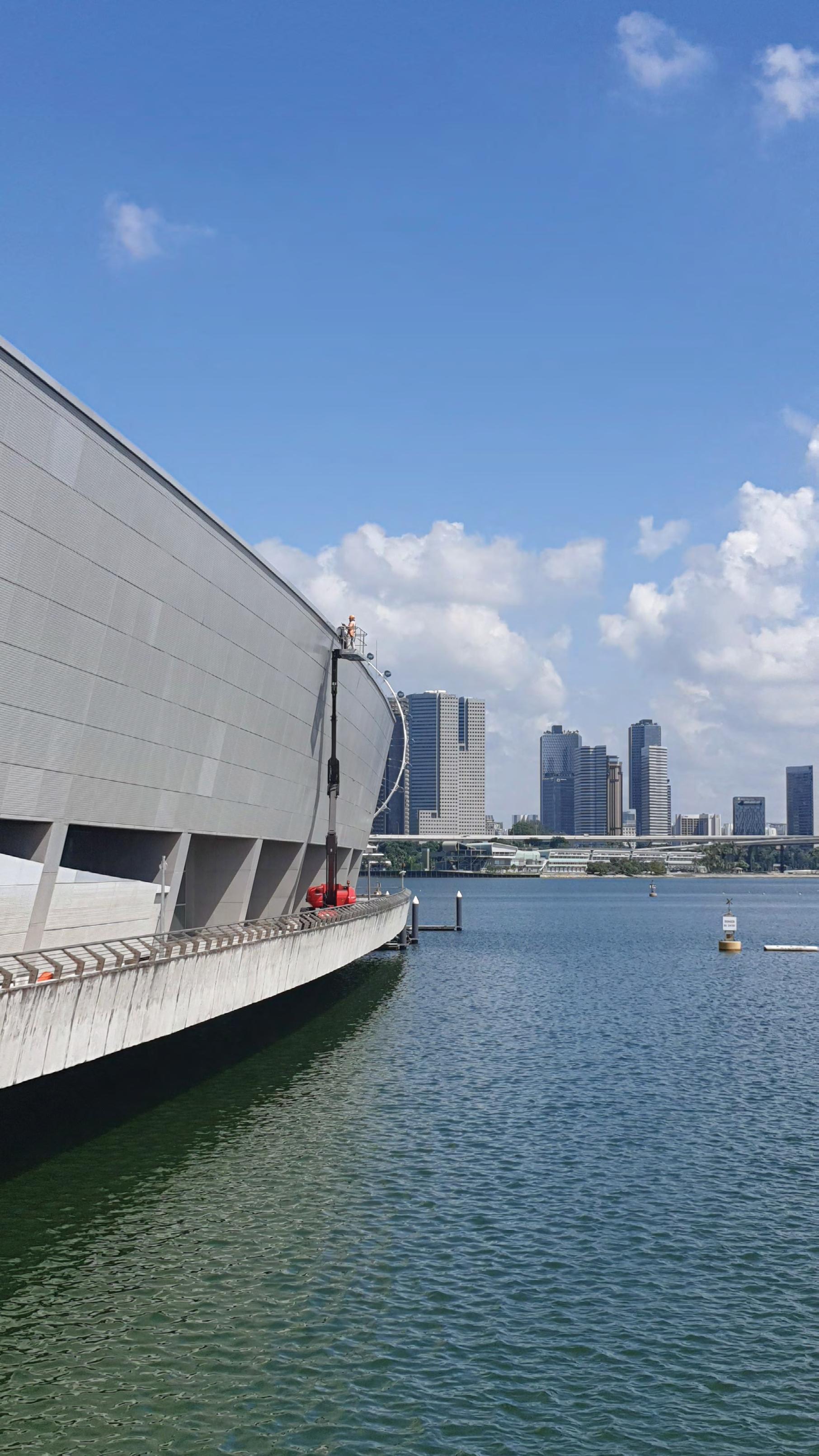
CIVIL & STRUCTURAL ENGINEERING: A realistic design option for large-scale renewable energy generation FAร ADE ENGINEERING: Establishing a Periodic Faรงade Inspection regime WORKSPACE HEALTH & SAFETY MANAGEMENT: Safe Working and Safe Living


Have your competency recognised!


CONTENTS FEATURES COVER STORY

10 Use of geogrid slopes in ABC Waters projects Reinforcement and stabilisation of the ground is achieved in an environment-friendly manner.

10

CIVIL & STRUCTURAL ENGINEERING

12 A realistic design option for large-scale renewable energy generation A simple structural concept is presented.

FAÇADE ENGINEERING

12

16 Establishing a Periodic Façade Inspection regime The article describes the initiatives taken in this regard, from conceptualisation to completion.

WORKING AT HEIGHTS

20 Ensuring safety and reducing the carbon footprint A leading manufacturer of Aerial Work Platforms provides an update on the company’s initiatives and products.

WORKSPACE HEALTH & SAFETY MANAGEMENT

16

22 Safe working and safe living Singapore’s Inter-agency Task Force (ITF), set up to manage the Covid-19 situation at the dormitories, is executing Phase Three of its plan.

20 President Prof Yeoh Lean Weng Chief Editor T Bhaskaran t_b_n8@yahoo.com

Publications Manager Desmond Teo desmond@iesnet.org.sg Publications Executive Queek Jiayu jiayu@iesnet.org.sg

Editorial Panel Dr Chandra Segaran Prof Simon Yu Dr Ang Keng Been Mr Gary Chiam Dr Victor Sim Mr Syafiq Shahul Dr Alexander Wiegand Media Representative Multimedia Communications (2000) Pte Ltd sales@multimediacomms.sg

Design & layout by 2EZ Asia Pte Ltd Cover designed by Irin Kuah Cover images by One Smart Engineering Pte Ltd, Singapore Published by The Institution of Engineers, Singapore 70 Bukit Tinggi Road, Singapore 289758 Tel: 6469 5000 I Fax: 6467 1108 Printed in Singapore

THE SINGAPORE ENGINEER May 2020

01


www.ies.org.sg

CONSTRUCTION LAW

24 The impact of Covid-19 on construction companies and the Covid-19 (Temporary Measures) Act 2020 An outline is provided on the various reliefs available to the construction industry and some of the legal issues.

CONCRETE TECHNOLOGY

26 Recent advances in CFRP deployment in concrete bridge repair Application of the material for the retrofit of structural components in specific US projects is described.

26

34 Effect of M-sand content on strength and durability performance of concrete A study was conducted on the effects of alternative, greener inputs on the final properties.

PROJECT APPLICATION

34

41 Capturing ‘reality’ in one of the world’s busiest airports The creation of an information-rich 3D model will assist in the operation of Changi Airport Terminal 2. 44 Assisting in the construction of Asia’s largest underground metro station Comprehensive formwork and scaffolding solutions were developed for the project in India. 46 Three new cranes on Swiss railway project Their compact dimensions mean ease-of-transportation and increased access, and the crawler tracks provide mobility.

41

REGULAR SECTIONS 03 INDUSTRY NEWS 47 PRODUCTS & SOLUTIONS 48 IES UPDATE

44

The Singapore Engineer is published monthly by The Institution of Engineers, Singapore (IES). The publication is distributed free-of-charge to IES members and affiliates. Views expressed in this publication do not necessarily reflect those of the Editor or IES. All rights reserved. No part of this magazine shall be reproduced, mechanically or electronically, without the prior consent of IES. Whilst every care is taken to ensure accuracy of the content at press time, IES will not be liable for any discrepancies. Unsolicited contributions are welcome but their inclusion in the magazine is at the discretion of the Editor.

02

THE SINGAPORE ENGINEER May 2020


INDUSTRY NEWS

SURVEY ON DIGITAL TRANSFORMATION IN THE CONSTRUCTION INDUSTRY Finalcad, a leading software provider to the construction sector, recently released the results of a survey on digital transformation in the construction industry. Taking part in the survey were 400 construction leaders in France, Spain, Singapore and Japan. The research finds the typical profit margin on a construction project averages only 2% across the four regions. It also reveals that a lack of digital transformation has left many companies reliant on manual and paper-based workflows. This comes at a time when the slowdown from the impact of the Covid-19 global pandemic is showing how important it is to digitalise operations and support remote working. Further, not digitalising is significantly damaging companies’ ability to collaborate and have a direct impact on the bottom line, with 62% of respondents saying that a lack of collaboration is the single biggest cause of construction project delays. The survey also investigates how universal tasks such as defect management and health & safety inspections are carried out. The findings show companies have several different methods and channels in place. More than half (51%) are using a combination of in-person, telephone, email, and/or paper to inform the person responsible for repairs of the next action. Surprisingly, 53% are using text/SMS or instant messaging to document a safety incident or hazard. The lack of consistency in how this important information is recorded and shared leaves a considerable margin for errors and miscommunication - which can lead to broader safety risks, delays and cost overruns. “The construction industry’s continued reliance on outdated processes - both on- and off-site - is causing significant inefficiencies. This is not sustainable in a sector where slender margins are a persistent issue”, said Franck Le Tendre, CEO, Finalcad. “Construction has fallen behind other global industries like finance and retail when it comes to digitalisation, yet this research shows us many of the daily processes that take place on all projects are prime targets for transformation. From snagging to safety, there is no area that cannot be improved by optimising operations. In addition, as regions emerge from the downturn caused by the Covid-19 pandemic, those that have digitised will be able to act quickly to get back to business as usual”, he added. Another consequence stemming from the failure to digitalise is the difficulty in capturing and documenting data, resulting in invoices being unpaid when a contractor cannot prove work has been done. A majority (90%) of respondents across all regions said this ‘free work’ was a common problem. Moreover, construction companies are guilty of ‘reinventing the wheel’ on new projects, with 59% saying that they create new templates for existing workflows some, most, or all of the time - a

Traditional methods to capture, document and share information, can be replaced by increased digitalisation, for better project outcomes.

clear waste of time and resources. Both results should be a major driver of digital transformation for construction managers, CEOs and developers. A centralised digital process enables continuous improvement and makes it far easier to proactively record extra work, as well as create repeatable models. The ‘Finalcad 2020 Leaders Survey: Exploring Digital Transformation in Global Construction’ is the first of a two-part series exploring digitalisation in construction. The second report will be published in Autumn 2020. The research was undertaken in February and March 2020. It was commissioned by Finalcad and conducted by independent market research company, Coleman Parks. The total sample size of 400 consists of 200 site managers/directors managing an average of 10 sites, and 200 HQ managers/directors. On site, respondents are the project lead with overall responsibility for a site. In the HQ operation, respondents are business unit directors with responsibility for construction. Respondents are from commercial and residential construction companies with revenues greater than USD 51 million per year, in France, Spain, Singapore and Japan.

Finalcad Finalcad is a collaboration platform designed to optimise the field experience for workers in the construction industry, particularly relating to buildings, infrastructure, and energy. It is said to help companies to carry out existing processes more efficiently and safely by digitalising their workflows. It captures data from across the whole site, facility or asset, arming all stakeholders - from the field worker, to the sub-contractor, main contractor and client - with the data they need to drive accurate decision-making. THE SINGAPORE ENGINEER May 2020

03


INDUSTRY NEWS

LTA AWARDS CIVIL CONTRACT TO CONSTRUCT INTEGRATED TRAIN TESTING CENTRE The Land Transport Authority (LTA) has awarded a SGD 639.5 million contract for the design and construction of an Integrated Train Testing Centre (ITTC) to GS Engineering and Construction Corp (GS Engineering). The ITTC is located at the former Raffles Country Club site, occupying approximately 50 hectares. The first of its kind in Southeast Asia, the ITTC is a dedicated facility that will be equipped to perform robust integrated systems testing for new and existing MRT lines. Integrated systems testing can be performed round-the-clock within ITTC, minimising the impact on passenger services. This is more efficient and frees up limited engineering hours on the existing lines for other activities such as maintenance and renewal works. When completed, the ITTC will be the cornerstone of Singapore’s strategy to sustain rail reliability and deepen core rail engineering capabilities.

The facility will commence operations in phases. The first phase of the ITTC is scheduled to open by end-2022 to receive new trains and systems for Circle Line 6. The ITTC is expected to be fully operational by end-2024. GS Engineering, the winning bidder, is a construction company based in South Korea, with an established track-record in the design and construction of MRT stations and depots, both in Singapore as well as overseas. The company is currently constructing the East Coast Integrated 4-in-1 Depot. It previously built the Downtown Line’s Gali Batu depot, Fort Canning Station and Tampines East Station, as well as the Thomson-East Coast Line’s Woodlands Station. GS Engineering also has prior experience constructing and operating a train testing centre in Osong, South Korea.

The ITTC will house an Operations Control Centre, testing equipment and features around 11 km of test tracks to enable new trains and supporting systems to be tested for endurance, performance integration and high-speed operation. The ITTC is equipped with a rolling stock workshop, stabling tracks and maintenance tracks to support the major refurbishment of existing trains. The design of the ITTC is modelled after similar testing centres in countries like Germany, South Korea and Japan. Over time, the ITTC will also serve as a hub for LTA and the local rail industry to deepen competencies in systems integration and operations and in maintenance, and to achieve engineering excellence. For example, the local rail industry will be able to evaluate new railway infrastructure, develop proofs-of-concept, as well as conduct research and development on railway technologies, using the ITTC as a testing ground. The ITTC will also speed up diagnoses and rectification of faults, as more troubleshooting can now be done locally. Meanwhile, rail workers stand to benefit with first-hand understanding of the intricacies of new rail systems before they are deployed. 04

THE SINGAPORE ENGINEER May 2020

Artist’s impressions of the Integrated Train Testing Centre.


INDUSTRY NEWS

BENTLEY SYSTEMS JOINS

DIGITAL TWIN CONSORTIUM Bentley Systems Incorporated, a leading global provider of comprehensive software and digital twin cloud services for advancing the design, construction, and operations of infrastructure, has joined Digital Twin Consortium at the ‘Groundbreaker’ level. Digital Twin Consortium was formed by non-profit trade association Object Management Group, with Ansys, Dell, Lendlease, and Microsoft, creating a global ecosystem of users who are accelerating the digital twin market and demonstrating the value of digital twin technology. As the authority in digital twins, the consortium brings together industry, government, and academia to drive consistency in the vocabulary, architecture, security, and interoperability of digital twin technology. Digital Twin Consortium aims to influence the direction of digital twin technology development, become the focal point for digital twin thought leadership, and promote, evolve, and refine digital twin best practices and benefits.

As a groundbreaker member of the consortium, Bentley will help set de facto technical guidelines and taxonomies, publish reference frameworks, develop requirements for new standards, and share use cases to maximise the benefits of digital twins. Bentley will be working alongside other early innovators, including the US Air Force Research Laboratory and New South Wales Government. Bentley’s collaboration with Digital Twins Consortium and its global ecosystem of digital twin users underscores a commitment to advancing an open-source platform for digital twins, which began with its release of iModel.js at its Year in Infrastructure 2018 Conference. iModel.js said to be the first and only open source library available on GitHub for accessing, creating, visualising, analysing, and integrating the data associated with infrastructure digital twins.

NATURE OF BUSINESS Facilitators Network Singapore provides professional facilitation training and services for effective corporate retreats, strategic planning, group decisionmaking, board meetings, stakeholder focus group consultation and engagement. Discount Offer: Facilitators Network Singapore offers IES members a 20% discount off the published fees till 30 June 2021 for the following workshops which will be extremely relevant for Engineers and Managers: VFW: Virtual Facilitation Workshop™ Learn the secrets to better communicate with others through effective virtual meetings and conference calls. FiT: SPOTlight on Facilitation in Training Workshop™ Transform your Training & Teaching to a highly participatory learner-centric retentive experience. M3: SIMDUSTRY® Managing 3 The first board simulation worldwide to perfectly integrate the 3 crucial success factors of management in one simulation: • People Management • Financial Management • Strategic Management

You become managers of competing companies striving for developing the most successful & reputable firm and learn management techniques in the process. The discount also applies for in-company customised workshops for members’ companies.

FACILITATORS NETWORK SINGAPORE PTE LTD 62 Ubi Road 1, #07-26, Oxley BizHub 2, Singapore 408734 Tel: +65 6444 5642 Mobile: +65 9833 3515 / 9383 4228 Email: admin@fns.sg Website: www.fns.sg

THE SINGAPORE ENGINEER May 2020

05


INDUSTRY NEWS

GRADUAL RESUMPTION OF

CONSTRUCTION WORK FROM 2 JUNE 2020 The Building and Construction Authority (BCA) will allow construction work to resume in a controlled manner in phases after the COVID-19 circuit breaker period ends on 1 June 2020. A gradual resumption is necessary, to minimise the risk of new COVID-19 outbreaks among construction workers. Since the circuit breaker period began on 7 April 2020, most construction work has been suspended. Currently, only about 5% of the construction workforce are working on very small number of critical infrastructure projects, and those that have to continue for safety reasons. From 2 June 2020, BCA will gradually allow more construction projects to resume. These would be projects that cannot be left idle for too long due to safety concerns, and critical and time-sensitive projects, such as MRT and Deep Tunnel Sewerage System (DTSS) tunnelling projects. Previously suspended residential renovation works will also be allowed to resume. BCA expects another about 5% of the construction workforce to gradually resume work in the month of June (making it a total of 10% of the construction workforce). All works will require approval from BCA before they can restart. Migrant workers in the construction industry must be tested before they are allowed to return to work. In addition, construction projects must put in place adequate safe management measures.

COVID-safe restart criteria Employers will be required to demonstrate their ability to meet the following three COVID-Safe restart criteria before projects are allowed to restart: • COVID-Safe Workforce: e.g. employers to establish a system to track the daily health status of workers, and to manage workers’ interactions on rest days. Regular COVID-19 testing for the workforce. • COVID-Safe Worksite: e.g. worksites to use national digital check-in system SafeEntry to record all entries and exits; strict safe management measures to be enforced at worksites to prevent outbreaks, such as segregating workers by teams into different work zones, and having staggered breaks. • COVID-Safe Worker Accommodation and Transport: e.g. cohorting of workers by projects at their places of accommodation. Providing dedicated transport between work sites and places of accommodation. BCA is working closely with the industry and the relevant Trade Associations and Chambers (TACs) to develop these criteria. 06

THE SINGAPORE ENGINEER May 2020

An Audit and Inspection regime will be implemented, using technology solutions to ensure that resumed projects are strictly observing COVID-Safe practices. More details are expected to be released soon.

Certain types of suspended renovation and building works to resume The Ministerial Task Force had earlier announced that there will be gradual resumption of construction works from 2 June 2020, including the following works that were suspended during the circuit breaker period: • Renovation works for residential units (that do not require building plan submission). • Building works for single dwelling landed properties (those that require building plan submission). All suspended renovation works in other types of buildings, new renovation works and new building works for landed residential properties will resume or start in a later phase. All companies are responsible for implementing precautionary measures to minimise the risk of COVID-19 outbreaks amongst workers. Companies intending to resume suspended renovation works (for both HDB flats and private residential units) or restart building works for landed residential properties (single dwelling unit) must apply for approval from BCA. Companies restarting building works for landed residential properties (single dwelling unit) must comply with BCA’s COVID-Safe Restart Criteria. Companies restarting renovation works will need to comply with the COVID-Safe Workforce and COVIDSafe Worker Accommodation and Transport criteria. Ministry of Manpower’s (MOM) Safe Management Measures are required to be implemented at workplaces after the Circuit Breaker period as detailed in the prevailing law and MOM’s advisory. All workers who are carrying out construction-related activities are also required to attend the COVID-Safe Training for Workers to be familiarised with COVID-Safe measures before restarting work. BCA will continue to work closely with the Trade Associations and Chambers, as well as the industry, to implement the necessary safety measures for the phased restart of construction and renovation works.


INDUSTRY NEWS

ARCADIS LAUNCHES NEW DIGITAL ASIA COST GUIDE

FOR CONSTRUCTION INDUSTRY Arcadis has launched a new mobile application of its annual Construction Cost Handbook and Quarterly Cost Reviews to the China, Hong Kong and Singapore markets. Known as the Asia Cost Guide, the app will provide users with the same construction cost data indicators, trends and analysis, now consolidated into the digital app, making it easier for users to have the latest information on hand. The Asia Cost Guide will provide real-time information and users can access data from multiple markets through a single source. With over 85 years of cost management experience, Arcadis understands the cost of construction and the impact it can have for the development of an asset. The Construction Cost Handbook and Quarterly Cost Review have served Arcadis’ clients, contractors and business

partners across Asia. The launch of the Asia Cost Guide is part of Arcadis’ continued investment to support digitalisation of the Cost & Commercial industry fostering knowledge transfer and best practice within the industry. The new app will also provide users with direct access to Arcadis’ latest thought leadership, research and publications, such as the annual International Construction Costs index, which ranks the cost of construction in cities around the world. The Asia Cost Guide is available to download now for free, and currently provides cost data for the China and Hong Kong markets and the Singapore market. Over the next few months, data for Malaysia, Philippines, Thailand and Vietnam will be added. A Simplified Chinese version will also be added which will be accessible on the China Android stores.

THE SINGAPORE ENGINEER May 2020

07


INDUSTRY NEWS

PASIR RIS AND PUNGGOL ESTATES ESTATES TO BE LINKED

BY CROSS ISLAND LINE EXTENSION With the Punggol extension to the upcoming Cross Island Line (CRL), commuters travelling between eastern and north-eastern Singapore will stand to save around half their current travel time, said LTA. The 7.3 km extension, which connects Pasir Ris to Punggol, will provide better rail connectivity and greater accessibility for those living in eastern areas such as Pasir Ris and Tampines North as well as north-eastern areas such as Punggol and Sengkang. The Punggol extension will be fully underground and comprises four stations, namely Punggol, Riviera, Elias, and Pasir Ris. Construction is expected to commence in 2022, with the stations opening by 2031. Other than Elias, the rest of the stations are interchange stations, which will enable commuters to transfer to and

from the East-West Line (Pasir Ris), North East Line (Punggol) and Punggol LRT (Riviera). This will shorten travel times and provide alternative travel options for commuters, as well as help to redistribute commuter load across the entire rail network. According to LTA, more than 40,000 households will benefit from the CRL-Punggol extension. The extension will also provide significant time savings for Punggol residents when they travel to eastern Singapore. For instance, they will be able to take the train to reach Pasir Ris within 15 minutes, less than half the time needed today using a bus (at around 40 minutes). The CRL-Punggol extension halves the time for commuters travelling from Punggol North to Loyang Industrial Area, from the 45-minute bus journey today to a 20-minute train ride on the Punggol extension when the line is ready.

RMIT researchers demonstrate feasibility of making stronger concrete with ‘sewage-enhanced’ steel slag Produced during the separation of molten steel from impurities, steel slag is often used as a substitute aggregate material for making concrete. Steel slag can also be used to absorb contaminants like phosphate, magnesium, iron, and aluminium in the wastewater treatment process, but loses its effectiveness over time. Engineering researchers at RMIT University examined whether slag that had been used to treat wastewater could then be recycled as an aggregate material for concrete. The concrete made with post-treatment steel slag was about 17 per cent stronger than concrete made with conventional aggregates, and 8 per cent stronger than raw steel slag. Water engineer Dr Biplob Pramanik said the study was the first to investigate potential applications for “sewage-enhanced” slag in construction material. “We’re missing the opportunity to wring out the full benefits of this material. Making stronger concrete could be as simple as enhancing the steel slag by first using it to treat our wastewater. “While there are technical challenges to overcome, we hope this research moves us one step closer to the ultimate goal of an integrated, no-waste approach to all our raw materials and by-products,” he said. In the study, civil and water engineering researchers found that the chemical properties of the slag were enhanced through the wastewater treatment, making it perform better when used in concrete.

08

THE SINGAPORE ENGINEER May 2020

Magnified images showing concrete made with treated slag (centre), conventional aggregates (left) and raw slag (right). The treated slag forms a more seamless bond with the cement paste, making the concrete stronger. Image: RMIT

Civil engineer Dr Rajeev Roychand said the initial study was promising but further research was needed to implement the approach at a larger-scale, including investigating the long-term mechanical and durability properties of enhanced slag. "There is great potential here for three industries to work together – steel making, wastewater treatment and construction – and reap the maximum benefits of this by-product," he said. The results of the study were published in the journal Resources, Conservation and Recycling.


INDUSTRY NEWS

A NEW INTERNATIONAL STANDARD ON MEWP OPERATOR CONTROLS The International Powered Access Federation (IPAF) has welcomed the introduction of a new International Standard regarding Mobile Elevating Work Platforms (MEWPs) operator controls. The new standard, ISO 21455:2020 has been published in April 2020 and is the culmination of a decade of work from IPAF, its members and the UK Health and Safety Executive (HSE), to standardise the actuation, displacement, location and method of operation of MEWP controls. The new standard is the result of work which commenced in 2010 when the UK HSE began to look into MEWP entrapment and control design. It also builds on research first undertaken by IPAF into which, methods of operation and orientation of MEWP controls might be standardised across different brands and models to further improve safety. The UK HSE research resulted in the reports RR960 and RR961 being published in 2013.

Chris Wraith from Access Safety Management Ltd, an IPAF member, and former IPAF Technical & Safety Executive, who worked to introduce the new standards addsed, “IPAF and its members were heavily involved throughout this 10-year journey and should be proud of their involvement in producing this landmark standard, which now sets a new international benchmark for MEWP control design”. IPAF North American manager Tony Groat, who is a member of ISO TC 214, said, “I believe this standard provides new language that can impact control designs to improve the operator’s intuitive direction of motion based on the position of the control panel - tilted towards or away from the operator. I am optimistic that this standard will immediately influence MEWP manufacturers and country design standards in their next revisions”.

Following the publication of the reports, the UK HSE and MEWP manufacturers began discussions through IPAF's Manufacturers’ Technical Committee (MTC) and the Association of Equipment Manufacturers (AEM) which resulted in the creation of the Manufacturers of Elevating Work Platforms Council (MEWPC), later termed as the MEWP Industry Manufacturers Group (MIMG). Human factors and ergonomics research work done by the UK's Health and Safety Laboratory (HSL) also played an important role. The outcome of this collaboration was a proposal in 2015 to develop an international standard for MEWP control performance, location, marking and method of operation, which has resulted in the release of the new ISO standard this April. In a research project led by IPAF and EWPA (Elevating Work Platform Association) in Australia, a simulated MEWP platform with a multi-position control panel was taken to construction sites and industry events. Operators of varying experience took part in a research exercise using the control panel. The resulting data proved invaluable to the members of the standard's development committee, ISO TC 214 Working Group 1, as they determined joystick controller orientation relative to the work platform floor. Peter Douglas, CEO and MD of IPAF, said, “This unprecedented co-operation between global MEWP manufacturers, trade associations and the UK HSE resulted in the new MEWP control standard. It shows how important IPAF’s committees are in driving forward standards globally and it is gratifying to see this project moving to fruition and improving the safety of MEWPs by standardising the controls”. THE SINGAPORE ENGINEER May 2020

09


COVER STORY

USE OF GEOGRID SLOPES IN ABC WATERS PROJECTS by Lee L G1, David Ng C C1, Victor Ong C W1, Or T W2, Or K M2, Oh E N2, Kance L2, David Ong C S1 and Jong H K1 Reinforcement and stabilisation of the ground is achieved in an environment-friendly manner. Cities are being exposed to the increasing threat of floods, due to rising sea levels induced by climate change and the increased frequency of extreme rain events, as well as increased urbanisation - resulting in more impervious areas and water runoffs.

the presence of geogrids. Figure 3 shows the typical cross-section of a geogrid-reinforced soil bio-engineered slope.

This is especially true of Singapore, a tropical island that has undergone rapid urbanisation over the past few decades despite its land constraints. The city state has an area of about 719 km2. The conventional approach of building wider and deeper drains to quickly collect and channel rainwater runoff away from the urban catchments is not sustainable as it is unable to cope with the large, often unexpected downpours of rain, resulting from climate change, against a background of limited land area and increasing urbanisation.

Figure 1: Geogrids delivered to site in rolls.

One of the drainage upgrading projects of PUB, Singapore’s National Water Agency, is at Sungei Tampines. The project includes the creation of a slope using soil bio-engineering and geogrids. Soil bio-engineering is the use of living plant materials to provide some engineering functions such as erosion control and it is an effective tool for treatment of a variety of unstable slopes or sites. Geogrids, made from high density polyethylene (HDPE), are used for reinforcement and stabilisation of ground structures. It is commonly used to construct steep slopes, retaining walls, bridge abutments and, further, to repair failed slopes and construct geocell structures. Geogrids are manufactured using select grades of HDPE resins that resist elongation (creep) when subjected to high loads for long periods of time. The geogrids carry large tensile loads applied in one direction (along the roll), and their open aperture structure interlocks with natural fill materials. Figures 1 and 2 show a typical HDPE geogrid.

Figure 2: The cross-section of a geogrid.

Soils pull apart under tension but geogrids are strong in tension. As a result, the stability of soil bio-engineered slopes is enhanced by ––––––––––––––––––––––––––––––––– 1One Smart Engineering Pte Ltd, Singapore 2Eng Lam Contractors Co (Pte) Ltd 10

THE SINGAPORE ENGINEER May 2020

Figure 3: Typical cross-section of geogrid-reinforced soil bio-engineered slope.


COVER STORY

Under this system, storm water runoff is expected to be managed in a more sustainable manner via the utilisation of natural systems consisting of plants and soil that are able to detain and treat rainwater runoff before discharging the cleansed runoff into the downstream drainage system. The geogrid-reinforced soil bio-engineered slope is an innovative and sustainable design option that has been adopted to line the canal. The geogrid can enhance the stability of the slope and, together with the geotextile facing and the plants, it can prevent soil erosion of the river bank. This is a good alternative to the construction of a reinforced concrete retaining wall for the canal and it also provides a good opportunity for greening the river bank, without having to worry about soil erosion. Figures 4 shows the laying of the unrolled geogrid before commencement of the work to build the geogrid-reinforced soil bio-engineering slope. The process of installing the geogrid is a relatively easy process as it comes in rolls that the workers can handle easily and the laying process does not require heavy machinery or cranes. After the geogrid has been laid, the soil backfill is placed on top and compacted, to achieve the relative density requirement. The process is repeated until the height of the slope is achieved. Besides the main reinforcement geogrid, there is also a facing geogrid and geotextile used in this project. There are many possibilities for the facing of geogrid-reinforced slopes or walls, such as keystone facing and geobags facing. In this project at Tampines Avenue 9, the facing design is based on a type of geogrid in combination with a geotextile wrapped around the facing and with

soil back-fill inside. This is to prevent soil erosion at the facing and yet allow plants to grow from the facing. Figure 5 shows a geogrid-geotextile combination facing that has been completed in the project, with plants starting to grow on it. Figure 6 offers a close-up look at the plants growing out from the facing of the geogrid-geotextile. Once the plants have grown well and have covered the whole slope, it will appear totally green and the geogrid-geotextile facing will be invisible. In conclusion, the advantage of using geogrids in construction is due to the fact that they are good in tension and have high ability to distribute load across a large area. The changing climate and damaging effects of CO2 on the environment, including climate change, have led to an awareness, throughout the construction industry, of the need to deliver more sustainable solutions. The use of a geogrid as reinforcement in a ‘naturalised’ slope, is a greener and more sustainable method for slope construction and is therefore a good alternative to the construction of a reinforced concrete wall as canal lining. Acknowledgement This study would not have been possible without the support from PUB, Singapore’s National Water Agency (the Owner); AECOM Singapore (the Main Consultant); and all parties involved in the construction work.

All images by One Smart Engineering Pte Ltd

Figure 5: Geogrid-geotextile combination facing that has been completed for the project, with plants starting to grow on it.

Figure 4: The laying of geogrids by workers is a relatively easy process.

Figure 6: A close-up of the plants growing out from the geogridgeotextile combination facing. THE SINGAPORE ENGINEER May 2020

11


CIVIL & STRUCTURAL ENGINEERING

A REALISTIC DESIGN OPTION FOR LARGE-SCALE

RENEWABLE ENERGY GENERATION by Bob L Y Cheung, Bob Cheung Offshore Consultants, Singapore Singapore is a small land-constrained island nation situated next to the equator, with a land area just over 720 m2 and a coastline of about 190 km. The main island is basically flat with few hills. The tallest hill is the Bukit Timah Hill which stands at a height of just over 160 m and is shorter than some of the skyscrapers in the downtown area of Singapore. There are few large reservoirs dotted over Singapore. Wind speed is usually very low. Even the Building Design Code does not specify high Design Wind Velocity in practice. Wave height around Singapore is also very small. The daily Significant Wave Height is usually less than 1.5 m. But there is a monsoon season that brings in heavy rainfall and modest wind although the season is relatively short. The population of Singapore is about 5.5 million. Having an undulated landscape, instead of a mountainous one, it is relatively less costly to build physical infrastructure and numerous HDB flats that are now home to 75% of its citizens. In fact, we now have over one million HDB flats in Singapore and 200 km of covered walkways. Keeping in mind all these natural constraints of Singapore, do we have the potential to harness large scale green energy within the boundaries of Singapore in a short time-frame and at a reasonable cost? The answer is a definite ‘Yes’ and the reason lies in a simple structural design concept that can provide Singapore the space it needs without having to intrude into its valuable land reserve. In this article, we shall discuss how we can use this simple structural design concept to generate large-scale green renewable energy that can provide electricity to 100,000 four-room households on a regular basis. When demand surges, this concept can be extrapolated to cover 200,000 households or more. Moreover, renewable energy generated through this design concept can be utilised to generate Green Hydrogen for other energy needs, if desired. Green Hydrogen is the fuel of the future. RENEWABLE ENERGY OPTIONS FOR SINGAPORE We will look at two options: wind energy and solar energy. As both are fluctuating energy sources, a standard electricity grid is still necessary to complement the renewable energy component. Each option has its own limitations and cost implications and we shall investigate each one in more detail.

Wind energy Wind energy is well developed in many countries in recent years. Is it suitable for Singapore? Electricity is generated using wing turbines. Bigger turbines and stronger wind speed will produce more electricity and more noise. Wind speed, which is governed by a mathematical equation in the Design Code, increases with height. Hence, taller and bigger turbines will collect stronger wind energy. This may pose a problem for low-lying Singapore as the basic daily wind speed near the ground is much less than 30 km per hour (18.6 mph). As a result, only limited electricity can be produced even if many wind turbines are collectively placed on top of 12

THE SINGAPORE ENGINEER May 2020

Bukit Timah Hill. In densely populated Singapore, it is often difficult to find large plots of empty land to install that many wind turbines, which are much taller than the neighbouring HDB blocks. Another problem we may encounter in Singapore is that tall wind turbines may interfere with the taking off and landing of aircraft at civilian and military airports. Building an offshore wind farm in Singaporean waters will also cause problems for shipping traffic. If the offshore farm is installed far out at sea, the cost of installing the turbines, building the needed central control platform, laying the subsea cables and the provision of security and maintenance will be astronomical. If we were to use the reservoirs in Singapore for a wind farm, water pollution issues during the construction, installation and maintenance phases will be a major concern. In addition, decision-making complications such as deciding on the ideal location (either in a shipyard or onsite) to fabricate the structures, deciding on the ideal location to assemble all the pieces including the turbines, deciding on the ideal method to put the turbines in the


CIVIL & STRUCTURAL ENGINEERING

water (either via a launch-way or a derrick barge), and deciding on the ideal method to put the construction vessels in the reservoir, will cumulatively have a huge cost impact on the project. The project time-frame will be very long. We do not believe wind energy is a cheap option for Singapore.

Solar energy Due to its geographical location, about 137 km north of the equator, solar energy may be the best option for Singapore. Yet, land scarcity poses a major obstacle. First, we need to understand exactly how much space is needed for solar generation. As reported in Sembcorp Marine’s annual report, the company plans to install solar rooftop panels in its new yard to generate 5,380 MWh of electricity per year, which can power 1,120 fourroom HDB flats annually. We shall use this number for further discussion. This number implies that each flat will consume about 400 KWh of energy per month, which is on the low side of the estimate. In certain parts of Singapore, the monthly energy consumption is more than 800 KWh on average, due to higher air-conditioning usage and higher daily washing frequencies. In a typical city in Western Europe, the electricity consumption can be as low as 240 KWh per month during certain months of the year, as a result of cooler temperatures which make air-conditioning unnecessary. In our discussion below, we shall assume a typical consumption rate of 450 KWh per month for a four-room HDB flat in Singapore. This works out to be 15 KWh per day. We further assume there are three peak-sun-hours available in Singapore each day and the solar panel has an output rating of 300 W, is 2 m by 1 m in size, and weighs 23 kg. We also assume a contingency factor of 30% since solar panels cannot work at 100% efficiency at all times. Based on these assumptions, we will need 22 solar panels and an area of 44 m2 to produce 15 KWh per day to support one household. However, we will use 45 m2 to simplify the presentation. To support 100,000 households consuming 15 KWh of energy per family per day, we will need 4,500,000 m2 or 48,442,325 ft2, which is equivalent to 700 football fields. Where can we find this space to produce 1,500,000 KWh of energy per day? Existing HDB rooftops can provide a partial solution. But, the rooftop space available in a modern HDB tower block, excluding the areas needed for water tanks, lift rooms and stairways, will not be enough to produce all the solar energy that is necessary to support the whole HDB block on a daily basis. If we were to use the 200 km covered walkways in Singapore to generate solar power, it can only support about 9,000 households, which is about three times the size of the smallest HDB estate in Singapore - Toh Yi in Bukit Timah. This is too small. Also, the 200 km walkways are distributed all over Singapore making it difficult to support a bigger estate. Building a solar farm in a reservoir is possible but it will be expensive and has problems in terms of fabrication

and installation as well as maintenance of the necessary structures.

The viable solution We believe that a viable and cost-effective solution for Singapore is to build a coastal solar farm. To be precise, it is an offshore solar farm that is bridge-connected to shore. In the initial phase, the farm will generate electricity for 100,000 households, but its electricity generation capacity must be scalable to support 200,000 to 300,000 households with ease. The design objective is to provide a structure that satisfies the following requirements: • The structure covers an area of 48,000,000 ft2 (simplified for discussion) to accommodate all the solar panels for 100,000 households. • The structure is fabricated in local shipyards. All sections are loaded-out and transported on barges without using road transport. • All sections are installed either using heavy lift barges available in Singapore or using the float-over method for installation. • The structure must not interfere with shipping traffic in Singaporean waters. • The structure should be fabrication-friendly, on a low man-hour per ton basis. The installation period should be kept to a minimum. • The structure should be designed such that it can be turned into a major attraction for locals and tourists. • The structure should be designed such that it can be made to accommodate a few food production farms. We propose to build a steel snake structure solar farm that measures 2,000 ft wide by 24,000 ft long (610 m wide by 7,314 m long) along our coastline - which is about 3.8% of Singapore’s coastline of 190 km (Figure 1). The design and the dimensions can be easily modified to suit fabrication and installation requirements. In other words, the structure can be in any form - straight, curved or circular. However, the design must be fit-for-purpose and low-cost. To do that, the design load-paths should be simple and clean. The structure must be without complicated details, thereby making it easy to build and maintain. The farm should be close to shore, to avoid ocean-going vessels and to facilitate construction. If required, electrolysers can be built onshore to produce Green Hydrogen for a more flexible green energy system. The deck elevation can be set at 50 ft above Mean-SeaLevel, to facilitate the passage of small vessels through the structure (Figure 1). Based on our offshore experience, we propose to use 26 numbers of 84 inch diameter piles, designed for both end-bearing and skin friction. This pile size is very big compared with that for onshore projects, but it can cut down fabrication and installation costs. The piles can be rolled from steel plates using suitable rolling machines available in local shipyards. For installation, the piles can be driven by steam or hydraulic hammers which should THE SINGAPORE ENGINEER May 2020

13


CIVIL & STRUCTURAL ENGINEERING

Figure 1: Two possible designs for the steel snake structure.

be available from several international offshore installation contractors based in Batam, Indonesia. Depending on the site-specific soil condition, we may encounter hard-driving situations, or we may face a necessity to acquire the required hammers from Europe, which can cost a few million Singapore dollars for mobilisation and demobilisation. Piles can be downsized to suit the situation. Instead of using 26 piles, we can use 48 piles of smaller size, that is, 4 piles per bridge unit. The installation time may increase, but the whole pile installation job can be done in less than 60 days. From the sketch, we propose two possible designs - a multi-two-way-span arch bridge and a truss bridge. Both designs have a clear span of 2,000 ft in X-Y directions. In fact, each bridge unit, measuring 2,000 ft by 2,000 ft, is a super long span bridge unit by itself. Obviously, the truss bridge is too expensive to build and unnecessarily complicated for a low-cost solar farm structure. There is no need for high rigidity and the standard Bridge-DesignCode or the Offshore-Platform-Design-Code should be modified to suit our need. To speed up the project, we should consider using a snake structure that is made up of 12 individual bridge units measuring 2,000 ft by 2,000 ft each. The whole job can be split up into a few contracts to keep all the local yards busy. Installation will not be a big issue as Singapore yards have several heavy lift barges capable of lifting more than 3,500 tons each. However, as the arch bridge is 550 ft above water, lifting can only be done in 14

THE SINGAPORE ENGINEER May 2020

a tandem lift arrangement. If each unit is too heavy, we can go for the float-over method. The 2,000 ft spacing provides ample space for this operation. The arch itself should be designed as a single steel pipe, not as a truss arch, to cut cost, if possible. The pipe size can be 48 in or bigger with many stiffeners. This is a cross-arch design and structural instability will not be a problem. The deck should be designed as a ‘perforated steel pancake’ with lots of openings to reduce weight. In order to reduce the free span of the deck beams, cables can be used to transfer the loads to the arch. The true span of each arch is 2,828 ft, which almost rivals that of the longest span arch bridge in the world. A simple roadway should be provided for construction and maintenance vehicles. A simple access bridge is needed to connect the snake structure to shore. Since this is a special design with a light weight deck, it must be verified in a wind tunnel test to avoid wind excitation. As an added benefit to the Singapore economy, the area below the solar farm steel snake structure can be turned into a tourist attraction. We can consider it as a 7 km long covered sea-walk. We can also use the solar farm for other purposes. For example, we can use part of the space, below deck but above the water surface, as a shallow-water fish farm, where seawater purity can be controlled to keep the fish healthy, and we can also use some of the area for food production. These options will not greatly affect the overall project cost as long as the additional loadings are reasonable.


CIVIL & STRUCTURAL ENGINEERING

Figure 2: A double arch design reduces the size of the chord members.

Assuming the final total steel weight is 100,000 t, the project cost can total up to SGD 500 million, excluding the solar panels. The cost attributed to each of the 100,000 households is estimated to be SGD 5,000. Using a payback period of 10 years, the cost to each household will amount to about SGD 42 per month. Adding on the operation and maintenance cost, the cost of the solar panels and the desired profit margin, the monthly bill for each household should still be affordable. We believe this project is within Singapore’s capability and it is an option that can be realised in 4 to 6 years. Before closing, it may be useful to identify what the likely technical factors, which may affect the project, are. The design team and the owner of the project should carefully consider each one of them. • For such a long-span bridge, the arch chord members are most likely to be large diameter tubulars. We can consider the arch as a very large diameter pipe made of a large number of large diameter elbows, arranged in a set curvature. Currently, there are only a few steel mills in the world that are capable of producing gigantic diameter elbows, which can considerably push up the cost. Delivery time of these elbows may be very long, taking up to six months to one year or longer. Therefore, it may be necessary to go for a double arch design to reduce the size of the chord members, as shown in Figure 2. This factor is important and needs to be considered early in the design.

• If the arch bridge is turned into a tourist attraction, the double arch design may provide more artistic appeal, but this will increase the cost of fabrication. • The proposed arch design is not limited to tubular members. We can use fabricated box members as a substitute, but the fabrication and quality control check will take a longer time. All the welds need to be 100% NDT and inspection time will be longer compared with a tubular arch. As a result, a lot more weld repairs may be necessary in the workshops. Extra work will increase the cost. • A bolted design is more time-consuming and expensive to build.

CONCLUSION This article investigates the possibility of developing a solar farm to support 100,000 households in Singapore. The calculation is based on a set of conservative assumptions, which may need to be reexamined during a feasibility study. For example, if we assume the peak-sunhours to be 5 hours per day, then the proposed structure can support 175,000 households. The uncertainty level should be about 30%. But the final conclusion indicates that the concept is workable. (More information can be obtained by emailing bob.cheung@rocketmail.com) THE SINGAPORE ENGINEER May 2020

15


FAÇADE ENGINEERING

ESTABLISHING A PERIODIC FAÇADE INSPECTION REGIME by Mathieu Meur, Director, DP Façade, Singapore The article describes the initiatives taken in this regard, from conceptualisation to completion. Introduction A few years ago, I was approached by Singapore’s Building and Construction Authority (BCA) with an interesting proposal. BCA wanted me to undertake a study of the regulatory regimes in force in other countries in relation to the preventive inspection of building envelopes. The premise was simple. The BCA enforcement team had come across an increasing number of façade failures in Singapore in the preceding years, fortunately with no major casualties so far. However, as we live in a densely populated high-rise cityscape with ageing building stock, it was felt that the risk of injury or a fatal accident would only increase with time. The intention of BCA was thus to look into the implementation of a framework for assessing the condition of the façade of buildings before they present a danger to the public at large. What followed was several months of intensive research, discussions and presentations, with a surprising overall finding - that very few countries had, in place, any form of mandatory periodic inspection of building envelopes. We did come across certain regulations, particularly in New York, Sydney and Hong Kong. Given the geographic proximity of the latter, as well as the rather rigorous inspection framework in place there, I made arrangements for a senior team from BCA to meet with the relevant people within the Hong Kong Building Department (BD, in short), so as to understand first-hand from them how the inspections were conducted, who conducted them, how often they took place, etc. After all, if Singapore was to put in place such a periodic inspection of building façades, nearly everything would have to be created from scratch. An entire framework would have to be devised, so we might as well learn from others what works and what could be improved.

The scope of work Fortunately, Singapore already had in place, for many years, a similar framework for the assessment of building structures, in the form of the Periodic Structural Inspection (PSI). The PSI must be conducted every 5 years by a Professional Engineer (PE). Its goal is to ensure that the structural components are safe for the continued use of the building. Some similarities could be drawn between this existing PSI and the upcoming Periodic Façade Inspection (PFI), but it was not possible to completely port over the entire structure of the PSI to the PFI, as the latter features a number of peculiarities. Firstly, some elements of the building envelope relate more to the 16

THE SINGAPORE ENGINEER May 2020

Mr Mathieu Meur

field of expertise of an architect than to that of an engineer. Secondly, while all structural engineers are (necessarily) familiar with building structural components, many (if not most) engineers are either not very familiar with, or have limited experience of, façade elements. Therefore, it became apparent very early on that it would require the involvement of both architects and engineers in what would become the PFI. The second, rather daunting conclusion, was that it would be necessary to conduct a formal course and evaluation of would-be inspectors, prior to the implementation of the PFI. A corollary to this was that trainers would need to be recruited in order to conduct the said course. The third observation we drew was that, given the very large volume of buildings that would need to be inspected, which is in the range of 4,000 or more per year initially, we would be required to train a very large number of inspectors, in order to be able to respond adequately to the demand generated once the PFI framework is enacted.

Void created by fallen stone facade panel.

Damaged stone cladding.


FAÇADE ENGINEERING

A pragmatic approach Building façades are exposed to weather elements and deteriorate over time. In some cases, this process may be fast and highly visible, but often, it involves a slow progression, and requires careful and close-up review in order to be identified. However, inspecting the entire façade would not be a practical approach, as it has a very high cost and requires a lot of time. In order to strike a balance between the commercial and technical aspects, while at the same time giving the inspectors the best chance of identifying critical conditions, a two-stage approach was adopted for the PFI. The first step requires the inspector to carry out a 100% visual survey of the façade from a distance. This can be done using a pair of binoculars, a camera with telephoto lens, or even a drone. The main criterion is that the entire building envelope must be covered by this remote survey. This next step consists in a close-up inspection of a minimum of 10% of the façade. The areas inspected should cover 10% of each elevation, as well as 10% of each different cladding system. The areas that fall within this minimum 10% are not chosen randomly, but can instead be informed from the initial remote observation, with a particular focus on areas that are suspected of having defects. In addition, the close-up inspection should also cover elements permanently attached to the façade, such as awnings, signage, lightning protection system, light fittings, etc.

Shattered glass facade.

Corroded fixing (above) and steel bracket (below).

The close-up inspection can be facilitated through the use of a number of simple and handy tools that allow the inspector to assess the condition of the building envelope without the need for dismantling part or the whole of it. Some of the useful tools an inspector may elect to carry include, depending on the type of façade being assessed, a protimeter (which measures the water content in walls), an infrared camera, a borescope, a metal detector, a magnet, etc. Some tools are more expensive, but not necessarily more useful than others. During the Certificate of Façade Inspection course, participants will learn which tool is most appropriate under a given set of circumstances.

Detached soffit panel. THE SINGAPORE ENGINEER May 2020

17


FAÇADE ENGINEERING

accredited with BCA or prescribed organisations. These individuals cannot become a CP, but they can instead earn the title of Façade Inspectors (FI). The relationship between a CP and a FI is much the same as that between a Qualified Person (QP) and a Resident Technical Officer (RTO). The CP may delegate some of his or her responsibilities to the FI, such as allowing the FI to carry out some or all of the inspections, which must be conducted under the CP’s direction and guidance. The CP remains the person responsible towards BCA when it comes to the contents of the inspection report. What should or need not be reported is clearly described throughout the various lectures. The Certificate of Façade Inspection course is 3½ days long. It covers technical aspects, case studies, legislative facets, as well as a handson portion where participants can familiarise themselves with different façade materials and inspection tools. This is followed by a written examination (in the multiple choice questionnaire format), in order to ensure that participants have assimilated the most important concepts.

Frequency of inspections Using a metal detector to locate fixings.

Access and safety considerations One of the possible concerns when undertaking a PFI is the availability of access to the façade. There may be no provision of permanent access, particularly in older buildings. In such situations, the roof layout, façade configuration, and even the ground floor surrounding the buildings, all need to be reviewed in detail, in order to devise temporary access solutions. Depending on these conditions, access could be facilitated through the use of temporary davit arms, a cradle supported from a counter-weight system, or by abseiling or Rope Access Technicians (RAT). For newer developments, particularly commercial buildings, permanent access is typically part of the building design. However, permanent access equipment is still required to be checked by a Professional Engineer within a year, in order to be used safely. For low-rise buildings, up to a height of 50 metres or so, access could also be provided from the ground, in the form of a spider-lift, scissor-lift or cherry-picker (collectively known as Motorised Elevated Work Platforms), or through the installation of temporary scaffoldings.

Training and certification As explained earlier, both Registered Architects and Professional Engineers can participate in the Certificate of Façade Inspection course. Doing so earns them an additional title as Competent Person (CP in short). Only a CP is allowed to make a submission related to PFI to BCA. However, a CP may not have sufficient time or may not feel comfortable inspecting a façade in person, suspended at height in a cradle, particularly so, when the cradle is suspended from a temporary hoist, and even more so, if no cradle is available, and close-up inspections need to be carried out by abseiling or RAT. Considering this possibility, the PFI course is also open to other individuals with relevant experience and interest, and individuals who are 18

THE SINGAPORE ENGINEER May 2020

The PFI regime aims to facilitate the early detection of façade deterioration and allow defects to be rectified in a timely manner. The intention is to detect signs of deterioration and to propose rectification works for the owner to carry out. In its initial implementation phase, the PFI will involve only buildings that are 20 years old or older, and 13 metres or more in height. The age parameter was adopted as it is comparable to the expected lifespan of some of the common materials. The PFI thus focuses on older buildings where maintenance may not have been thoroughly conducted over the years, or where heavier maintenance operations might currently be required as a result of dilapidation over time. After the initial inspection, the PFI needs to be repeated, at most, every seven years. This differs slightly from the five-yearly PSI. One of the reasons for adopting this different period between inspections is to minimise the cost of access involved in the inspections, as the latter could be carried out at the same time as the regular repainting of the building exteriors, which has to be carried out at most every seven years. Another reason for selecting this interval between successive inspections is that it is expected that, with a thorough inspection, followed by regular maintenance, and in the absence of an external detrimental factor, the façade elements should not overly degrade within this period.

Summary This has been a long and eventful journey, from the first brain-storming session at a meeting in the old MND Complex, through the conception of the course, the training of several hundreds of would-be inspectors, and finally to the enactment of the PFI regime. Looking back, though, I am convinced that it was all worth the effort put in by all those involved, and that Singapore now has in place, one of the most robust and comprehensive façade condition assessment regimes in the world, which will improve the safety of our buildings and their occupants.


FAร ADE ENGINEERING

Temporary counter-weight system for faรงade access.

Safe access for inspections using the Building Maintenance Unit (BMU). THE SINGAPORE ENGINEER May 2020

19


WORKING AT HEIGHTS

ENSURING SAFETY AND

REDUCING THE CARBON FOOTPRINT Manitou Asia showcased a range of Aerial Work Platforms (AWPs) at the Manitou Center Singapore in December 2019. ‘The Singapore Engineer’ learns more about the company’s initiatives and its products, from Mr Bernd Freudenmann, Vice President of Manitou APAC and Managing Director of Manitou Asia. The Singapore Engineer: What are some of the unique features of Manitou AWPs, that leverage on the company’s experience with and expertise in telehandlers? Mr Bernd Freudenmann: All our rough terrain telehandler machines have axles. Like these telehandlers, our rough Mr Bernd Freudenmann terrain AWPs typically have two axles, including an oscillating front axle. This axle is an absolute necessity for stability, eliminating the risk of toppling and enhancing safety on uneven ground. The standard for Manitou AWPs is to have oscillating axles as a core safety feature. Heavy duty axles are much more lasting, hence making the machines very robust. TSE: How is Manitou looking to support the construction and industrial sectors in Asia through the AWPs? BF: At Manitou Group, we tap on the latest technological advancements to design and build innovative machines that are tailored to our users’ requirements and hence to better serve the construction and industrial sectors. Every machine produced by Manitou is now a ‘connected machine’ which is commonly referred to as a ‘smart machine’. We adopt it as a standard, to allow users to fully harness the benefits offered by the Internet of Things. A connected machine can provide real-time access to machine data, remote access, remote diagnosis, and even remote troubleshooting, to realise better service levels and improved utilisation. With connectivity, users can plan their maintenance well in advance, to optimise uptime of machines. End-users, rental companies, and manufacturers can track the machine status, running hours, and the machines’ operating parameters like potential errors codes. Envisaging connectivity as a very big benefit for end-users, rental companies and dealers, we have incorporated it as a standard in our machines to support our customers’ requirements. Connectivity also enables the prompting of maintenance scheduling via the app, MyManitou. Users can send photos on site through MyManitou, or go to their Manitou dealer directly, depending on their preference. 20

THE SINGAPORE ENGINEER May 2020

TSE: How do you see connected machines or smart machines changing the AWP business? BF: With connected machines, we can optimise the total cost of ownership of the machines by detecting any potential issues remotely and solving them quickly. It is a more proactive approach because a user will know the running hours in terms of both pricing and maintenance. For example, if a customer rents the AWP for eight hours and the machine runs overtime, the overtime fees will be charged accordingly. This would allow for a more dynamic pricing depending on the usage of the machine. By carrying out the right maintenance, the customer could also optimise the machine’s resale value. Every machine has an optimum selling point after which the costs for maintenance will increase and compromise profitability. The connectivity feature also helps in the tracking. TSE: How is Manitou contributing to the worldwide push towards sustainable development? BF: As part of a committed CSR policy, Manitou Group launched a dedicated programme called ‘REDUCE’. We were the first manufacturer in our sector to inform users about the energy consumption of our machines, using a special calculator. Further, there is a growing trend in electrification, worldwide. The European and Japanese markets are ahead in the electrification of construction machinery. China will also play a major role in influencing the trends in electrification, in the region. In order to move away from fossil-fuel (diesel)-powered machines, we have been manufacturing electrical machines such as forklift trucks and warehousing equipment for many years. It was a natural progression for us to extend low-emission solutions to our other ranges such as AWPs. Manitou created the Oxygen label for low-emission solutions. The first fully electrical rough terrain AWP is the 200 ATJ E, a 20-metre articulated AWP which will start serial production in 2020. TSE: What are the differences between the electrical Oxygen 200 ATJ E and the non-electrical version of it? BF: The Oxygen label is created for every low-emission solution. We recently launched our full range of electrical machines, with plans to launch hybrid machines in the next phase.


WORKING AT HEIGHTS

Conventional rough terrain machines use diesel engines. However, there is a growing trend in our industry towards electrical engines. We are analysing usage trends before orienting ourselves to a particular energy option. In countries where the trend is being driven by the government or municipal regulations, we are ready with the solution. Electrical machines might not be suitable for operation in every location. For example, in some remote locations where there is no option to charge overnight, diesel-driven machines will enable operations to run uninterrupted. On the other hand, a hybrid machine is something in-between. It is designed to give users, who are unsure about bringing the machine back in the evening for charging, the option of using diesel to charge the battery to continue operation. TSE: How important is the Oxygen 200 ATJ E machine in transforming the current AWP landscape in Asia?

will increase our capacity to meet the demand of AWPs in the European, US, and Asian markets. This will allow us to expand and develop our product range further, such as investing in new boom lifts. Manitou Group is currently en route to expanding its businesses in the US and Asia. In 2019, we expanded our global footprint in Asia Pacific with a new office in Japan and a new Manitou Center in Sydney. Our increased presence in Asia has enabled us to support our dealers and key accounts directly. As providing service support is of utmost importance to us, we have recently expanded our parts warehouse in Singapore to increase parts availability and enable delivery of parts to our customers across Asia Pacific within 24 hours. Our new factory will certainly support the above objectives.

BF: The first batch of our Oxygen label machines will be produced for the Australian market, with plans to expand into the Japan and Korean markets. At this point in time, Europe has gone far ahead in the direction of electrification, and can be viewed as a case study for other countries. In Asia Pacific, Australia is next in line for projects like tunnelling which is one of the applications that seem suitable for full electrical machines. Strict regulations are implemented in such projects, to ventilate the airflow of tunnels, and we believe the adoption of electrical machines will continue to grow. Asian countries such as Japan, Korea, and China are moving towards electrification, due to the push by the respective governments. Together with the growing environmental awareness, also in other countries such as Singapore, I believe that it will get relatively easier to adopt electrification. TSE: What do you think are some of the challenges faced by Manitou in bringing the electrical machines to Asia? BF: One of the challenges is to gain acceptance from potential users. Awareness of the benefits of electrical machines is still low, leading to hesitation to try them. Manitou will bring these machines to the customers for trial and testing, to build customer confidence. Our goal is for users to realise the ease and convenience of charging electrical machines, instead of relying on diesel, as more global cities are becoming more conscious about emissions and environmental impact. Currently, our machines are designed to last for a full day with overnight charging. In the future, the capacity of the batteries can be extended to last for multiple days before requiring the next charging operation. As a metropolis with wide access to electricity at most job sites, Singapore has the potential to adopt a wide range of electrical machines. TSE: How would your customers in Asia benefit from your new AWP factory in Candé, France? BF: As we have reached the limits in production capacity in our current factory, the new factory in Candé, France

One important application of Manitou machines, in the context of Singapore, is in façade inspection and maintenance, especially in light of the proposed changes to the Building Control Act, that will make façade inspections mandatory for older buildings. Main Image: FanchRonan, Manitou Asia Pte Ltd. Inset Image: Vincent Koay, Manitou Asia Pte Ltd. THE SINGAPORE ENGINEER May 2020

21


WORKPLACE SAFETY & HEALTH MANAGEMENT

SAFE WORKING

AND SAFE LIVING Singapore’s Inter-agency Task Force (ITF), set up to manage the Covid-19 situation at the dormitories, is executing Phase Three of its plan, which is to prepare for the recovery of dormitories, and the safe and gradual resumption of business activities. In the coming weeks, the ITF is aiming to recover dormitories or dormitory blocks, housing up to 60,000 migrant workers (around 20% of all dormitory residents). The ITF will systematically and progressively recover all remaining dormitories in the coming months, by testing and clearing all the residents. It will then ensure that these dormitories implement Safe Living protocols to ensure residents are kept free from infection as they prepare to resume work.

As the dormitories fill with recovered workers and workers who tested negative for Covid-19, dormitory operators, employers and workers have to strengthen dormitory management practices and accept necessary changes to their way of life, so that workers can live in dormitories safely. The changes will impact the workers’ movements, and how they interact and socialise with one another.

In tandem with the implementation of Safe Living protocols, companies are instituting industry-specific measures to ensure that workplaces are Covid-Safe.

Tighter control of entry & exit

As Singapore moves towards gradually easing circuit breaker measures, the twin emphasis of ‘Safe Working and Safe Living’ will help to reduce the risk of subsequent waves of infection.

SAFE WORKING To prevent the re-emergence of community cases as workers return to work, the tripartite partners have issued ‘Requirements for Safe Management Measures at the workplace’. Employers who are allowed to resume their operations are required to implement these measures to protect their workers. Sector-specific Safe Management requirements, such as for food and beverage (F&B) establishments, retail establishments, shopping malls, F&B and online retail delivery and for consumers have been set out by Enterprise Singapore. The Economic Development Board has also established Safe Management Measures for the manufacturing sector, and will be doing the same for the marine and process sectors.

For a start, residents from BRWs will only be permitted to leave for the purpose of work and must return to the BRW after work. This is conditional on their workplace being allowed to operate, and the implementation of Safe Management requirements. At some point, once the outbreak in the dormitory has been brought under control, it will be possible to consider allowing residents from BRWs to also leave the dormitory for non-work reasons. But the workers will still need to adhere to the prevailing safe distancing measures, which also apply to the rest of the community in Singapore. For example, they cannot gather in large groups, and additional measures will have to be taken to reduce crowd sizes at the popular locations where workers tend to gather. More details will be shared at a later date.

The Building and Construction Authority (BCA), in consultation with relevant Trade Associations and Chambers (TACs), will be issuing a set of Covid-Safe Restart Criteria for the resumption of construction work.

Limit intermixing of workers

SAFE LIVING

Dormitory operators will be required to set up barriers and marked routes from dormitory blocks to common areas and entrances. This will prevent intermixing of workers from different blocks. Within each block, residents will have to continue to stay within their level and rooms, and not move freely to other levels. Within the shared toilet facilities, specific showers, wash basins and toilets will be marked out for occupants of the same room. In other dormitories, residents will already have access to en-suite toilet facilities. Stoves in communal kitchens will

The ITF previously announced the designation of specific Blocks for Recovered Workers (BRWs) to house recovered workers who will be returning to their dormitories. The rooms and blocks will be progressively cleaned out and disinfected across the dormitories, to prepare for the return of recovered workers. Since then, more than 2,000 beds have been created in BRWs. By 18 May, all 43 dormitories were expected to have about 5,400 beds. 22

A BRW will be physically segregated from the rest of the dormitory. When a BRW has been occupied by recovered workers or workers who tested Covid-negative, the entry and exit of its occupants will be allowed to begin in a carefully regulated way. This will reduce the risk of Covid-19 re-emerging. Dormitory operators will be required to track all movement in and out of the dormitories.

THE SINGAPORE ENGINEER May 2020

Dormitory operators will have to put in place measures to limit intermixing of workers, so as to minimise the risk of transmission.


WORKPLACE SAFETY & HEALTH MANAGEMENT

be assigned to individual rooms to prevent intermixing during cooking. When leaving for and returning from work, there will be designated and segregated waiting areas, and staggered pick-up and drop-off timings. Dormitory operators should also reduce human traffic at communal areas. Minimarts, canteens and shops must operate contactless ordering, such as through calls, text messages or online ordering. Residents will be provided timeslots to use other communal facilities such as kitchens and outdoor recreational areas.

Remaining vigilant Residents will continue to be tested regularly. They will have to report their temperature, oxygen level and heart rate daily. The daily report sick routine will have to be sustained. Residents who are unwell will have timely access to medical support from the onsite or regional medical posts, as well as tele-kiosks. If a resident is tested Covid-positive, close contacts of the infected worker will be isolated or quarantined expeditiously either in onsite or community isolation facilities. Aggressive testing will be done to cut transmission chains. Many of these measures are already implemented at the dormitories during this period of isolation. The ITF and Ministry of Manpower (MOM) will work with the Dormitory Association of Singapore, and dormitory operators to ensure they continue to be implemented effectively.

STAY-HOME NOTICE FOR CONSTRUCTION WORKERS NOT LIVING IN DORMITORIES On 20 April, construction work permit and S-pass holders and their dependants, were placed on stay-home notice (SHN). The SHN was scheduled to end on 18 May 2359 hours, by which time the workers and their dependants would have served 28 days of self-isolation. After the SHN, these workers have to continue to adhere strictly to circuit breaker measures, in line with what the rest of the community is subjected to. Everyone is urged to stay in their residences and avoid going out except to purchase food and daily necessities, procure essential services or for urgent medical needs. If it is necessary for them to leave their residences, they should do so alone and return to their residences immediately after completing their errands. Everyone must observe the circuit breaker measures strictly so that transmissions can be broken quickly and the number of cases brought down. At the same time, employers are required to keep MOM updated should there be any change to the registered addresses and mobile numbers of their workers.

CONCLUSION The ITF has thanked workers, employers, dormitory operators and the community for their contributions and effort in dealing with Covid-19, and urges everyone to remain vigilant in the weeks and months ahead, and ensure the effective implementation of Safe Working & Safe Living for the protection and benefit of all.

Providing better care for migrant workers In view of the evolving Covid-19 situation, MOM has introduced new resources to provide better care for migrant workers. MOM has developed a new ‘FWMOMCare’ mobile app for workers to self-monitor and report their daily health status. Workers are expected to use the app to record their temperatures twice daily, and indicate if they have a cough, sore throat, runny nose, or shortness of breath. If the worker reports any symptoms, the app will prompt him to seek medical assistance. A doctor will also be alerted and will contact the worker within 30 minutes to provide a teleconsultation. Employers should encourage all their Work Permit and S-Pass holders to download the FWMOMCare mobile app and register themselves as users. The mobile app is available for download for Android devices (www.mom.gov.sg/fwmomcare-android) and iOS devices (www.mom.gov.sg/fwmomcare-ios). To contain the transmission of Covid-19 at the dormitories and provide medical support to confirmed cases, the Inter-Agency Task Force (ITF) has moved some workers to other locations such as alternative housing, community care facilities (CCF) or community recovery facilities (CRF). Due to the urgency of the situation, it has not been possible to keep employers updated on the latest location of their workers, although employers have been able to stay in touch with their workers via the free data SIM cards provided to them. To keep employers updated on the latest movements of their workers, MOM created a new ‘Government Facilities Listing’ feature within the Online Foreign Worker Address Service (OFWAS). Employers can use this feature to check on the location of their workers who have been moved by the ITF. MOM will continue to improve this new OFWAS feature, including shortening the time between movement and updating of the listing. To facilitate contact tracing should there be an infection, the following groups of migrant workers who stay or work in higher risk settings will be required to download, activate, and maintain the latest version of the TraceTogether mobile app, available from 1 June: • Workers staying in all dormitories (i.e. purposebuilt dormitories, factory-converted dormitories, construction temporary quarters and temporary occupation licence quarters). • Work Permit and S-Pass holders who work in the Construction, Marine and Process sectors. • The mobile app is available for download for Android devices and iOS devices (https://www. tracetogether.gov.sg).

THE SINGAPORE ENGINEER May 2020

23


CONSTRUCTION LAW

THE IMPACT OF COVID-19 ON

CONSTRUCTION COMPANIES AND THE COVID-19 (TEMPORARY MEASURES) ACT 2020 by Jimmy Yap, Accredited Adjudicator (Partner) and Daphne Tan (Associate), CNPLaw LLP, Singapore The COVID-19 pandemic has had an enormous impact on various industries worldwide. Whilst generally well-managed, the tightened safe distancing measures in Singapore have obviously affected the work flow and cash flow of construction companies here, regardless of size. Passed by Parliament swiftly, the COVID-19 (Temporary Measures) Act 2020 (“Act”) aims to provide temporary relief to companies and business-owners who now find themselves suffering cash flow issues where those issues have been caused in a material part by the pandemic. We outline here the various reliefs available to those in the construction industry for general information and briefly explore the other likely legal issues that construction companies will face in the coming months. The statutory moratorium Part 2 of the Act enables contractors to avail themselves of a statutory moratorium once they have served a notification for relief. A moratorium is a restriction against a party commencing or continuing legal action against you - meaning, suing or continuing to sue you in court or through arbitration. The moratorium is statutory because it is prescribed by the law and cannot be “contracted” out of. You will be able to serve a notification for relief if the matter, for which you are being sued or being threatened with legal action, relates to your inability to perform a contractual obligation. The contractual obligation must relate to a contract entered into before 25 March 2020, and your inability must, to a material extent, have been caused by a COVID-19 event. A COVID-19 event includes the passing of any law which would operate to prevent you from carrying out your obligations or which prohibits or prevents your company from continuing work on the construction project. A notification for relief can be challenged by the party being served with the notification (meaning, the party suing or threatening to sue) by a quick process known as an “assessment”. The Minister for Law has appointed a panel of assessors, and once an application for an assessor’s determination has been filed, an assessor will be appointed to determine whether the notification for relief is valid. If the assessor determines that the notification for relief is not valid (for example, because the notifier’s inability to perform their contractual obligation was not due, in material part, to a COVID-19 event), the statutory moratorium will not prevent the applicant from suing or continuing to sue the notifier. Part 2 also prohibits the making of immediate calls on a performance bond, and prevents liquidated damages from being imposed from 1 February 2020 to the expiry 24

THE SINGAPORE ENGINEER May 2020

of the prescribed period. The Minister for Law has ordered that the prescribed period be a period of 6 months commencing on 20 April 2020. This period may be shortened or extended more than once by the Minister, by notification in the Government Gazette.

Adjudication Applications under the SOP Act It is important to note that the Act does not prohibit the filing of adjudication applications under the Building and Construction Industry Security of Payment Act (“SOP Act”). Parties can continue to file adjudication applications under the SOP Act as such applications do not fall within the matters prohibited by the statutory moratorium. However, it should be noted that whilst you may indeed be able to obtain a favourable adjudication determination which entitles you to payment from the respondent, you will not be able to proceed to enforce that determination as of right if the respondent is unable to pay you. In other words, you may not be entitled to obtain the court’s leave to enforce the determination as a judgment debt. This is because whilst the filing and hearing of an adjudication application does not fall within the actions prohibited by the moratorium, the enforcement of an adjudication determination does. Hence, the respondent may be able to avail of the statutory moratorium discussed above, should you attempt to enforce the determination. Therefore, if as a claimant, you are aware that the respondent is suffering cash flow issues due to a COVID-19 event, you may wish to reconsider filing an adjudication application; as although you may be able to obtain a favourable determination, you may not be able to compel the respondent to pay you timeously.

Salaries due to employees and cost-cutting measures An important exception to the Act is that it does not relieve any company or any business-owner of the obli-


CONSTRUCTION LAW

gation to pay their employees. The COVID-19 (Temporary Measures) (Temporary Relief for Inability to Perform Contracts) Regulations 2020 contains an express carveout for employees. As such, whilst as a company you may be experiencing cash-flow issues, due to your inability to progress works on a construction project and/or the statutory moratorium preventing you from enforcing favourable determinations against your employer or main contractor, you must still ensure that you pay the salaries due to your employees. You may have to consider external financing to tide you over this period, or alternatively, cost-cutting measures. If you are considering cost-cutting measures, you must ensure that you treat your employees fairly. You cannot unfairly discriminate against local employees, and you must serve the Ministry of Manpower with the relevant mandatory notifications within 1 week after you have implemented these measures. If you have foreign employees or if you are a foreign director of a company and you wish to voluntarily take no-pay leave to support your company during this time, you must also notify the Ministry.

Force majeure and frustration Apart from the moratorium, you may also wish to consider whether the impact of COVID-19, resulting in your inability to perform a contract, constitutes a force majeure event, or whether it has frustrated your performance of the contract. Whether or not you can rely on the force majeure clause to suspend your performance depends on the precise wordings of the clause, which generally will have to be strictly interpreted. Whether it can be said that COVID-19 has frustrated your performance of your obligations under your contract is also fact-sensitive and you will have to consider these carefully. These considerations also apply to cross-border contracts or those governed by foreign law and if relevant may absolve you of liability for your inability to perform your obligations timeously and/or for any liquidated or other damages that you may otherwise be liable for.

The heightened criteria for bankruptcy and winding-up applications Part 3 of the Act temporarily modifies the provisions of the Bankruptcy Act and Companies Act which relate to bankruptcy and corporate insolvency. It should also be noted in passing that the Act goes further so as to provide for a presumption that any debt incurred by a person or a company, that is in the ordinary course of their business during the prescribed period, was not incurred fraudulently. The general position under the law prior to the Act is that a bankruptcy application can be filed by or against an individual and a company if the individual owes an undisputed debt of not less than SGD 15,000 and in the case of a company, an undisputed debt of more than SGD 10,000 and if the individual or company has failed to satisfy a statutory demand for that debt before the expiry of the statutory demand (i.e. three weeks). However, with the Act now in force, for the duration of the prescribed period, the threshold debt for individu-

als is now not less than SGD 60,000 and for companies, more than SGD 100,000, with the statutory demand only expiring and forming a basis of a creditor’s bankruptcy or winding-up application after 6 months have passed from effective service. As noted above, the prescribed period is a period of 6 months commencing on 20 April 2020, and may be shortened or extended by the Minister for Law. Disclaimer: This article is provided as general information and should not be relied upon as legal advice. (More information relating to this article and the subject matter discussed may be obtained by emailing jyap@ cnplaw.com or dtan@cnplaw.com)

RICS implements lowvalue dispute construction adjudication service The Royal Institution of Chartered Surveyors (RICS) has begun providing a low-value dispute construction adjudication service to give UK SMEs a simple and cost-effective procedure that will make solving disputes more accessible and quicker for lower value claims - something that is badly needed in these challenging times to free up SME cash flow. The RICS service will operate in accordance with the ground-breaking CIC Low Value Disputes Model Adjudication Procedure (LVD MAP). The LVD MAP complies with the Construction Act and includes an uncomplicated timetable and structure. It provides a flexible, yet simple-to-understand, approach to the key elements of the adjudication process and can reduce the amount of reliance parties may need to place on professional representation. Crucially, the procedure is relatively inexpensive, and both sides will know beforehand how much the adjudicator will charge and how much each will have to pay. The service is aimed at disputes where the amounts claimed are for GBP 50,000 or less, and the issues in dispute are relatively uncomplicated. In light of the impact of the coronavirus on the industry, there is a renewed call for an easy-to-use method. RICS has set up a high-quality panel of RICS adjudicators who have been trained to deliver the service. RICS is a key supporter of the CIC LVD MAP which was set up as a direct response to concerns that adjudication had become too costly and complex for smaller amounts, and has been involved in its development over the last two years. RICS' new low-cost adjudication service is directed at small and medium sized construction businesses in the UK.

THE SINGAPORE ENGINEER May 2020

25


CONCRETE TECHNOLOGY

RECENT ADVANCES IN CFRP DEPLOYMENT

IN CONCRETE BRIDGE REPAIR by Abheetha Peiris, Kentucky Transportation Center, University of Kentucky and Issam Harik, Department of Civil Engineering, University of Kentucky, USA The deployment of carbon fibre reinforced polymer (CFRP) for the retrofit of structural components has been gaining momentum over the past three decades. This is a result of its ease of application, design guides and standards, and familiarity with the material. Over the past decade, experimental and analytical studies were conducted at the University of Kentucky on a new family of CFRP systems called CatStrong. These include (1) the modular CFRP rod panels that can be applied by a single worker on bridges with limited access (e.g. over waterways, overpass bridges, valleys, etc) thus reducing the dependence on construction equipment and labour, (2) uni-directional and multidirectional fabrics, and (3) procured CFRP pile/pier wraps. CatStrong systems restore and/or increase the capacity of reinforced and prestressed concrete structural components (e.g. girders, piers, piles, walls etc). They are ideal for deteriorated and impacted bridge or building components. CatStrong has been deployed on more than 20 bridges in Kentucky, with retrofit costs between 10% and 50% of other retrofit alternatives. Retrofit details of several reinforced and prestressed concrete structures are presented. INTRODUCTION While the need for more investment in the nation’s overstressed infrastructure is paramount, effective upkeep of existing infrastructure will minimise future funding requirements. The rapid retrofit, strengthening, and repair of structurally deficient bridges extend their service life, while letting them carry larger loads - sometimes at higher frequencies - than they were initially designed for. By the end of 2010, approximately 200,000 US bridges had exceeded their 50-year design life [1]. The use of novel high-performance materials for bridge retrofit is one strategy to extend the service lives of ageing bridges. High-performance materials can have very high strengthto-weight ratios and are suitable for efficient structural repair of deficient bridge members. The ability for rapid placement and the use of minimal labour is one of the many advantages that these materials offer. Fibre reinforced polymer (FRP) composite materials, especially carbon fibre reinforced polymers (CFRP) - initially developed in the aerospace and automobile industry - have become popular for strengthening bridge components. Rapid repair of impacted, damaged, or deteriorated concrete bridge components prevents irreversible damage, to the structural integrity of the bridge in the future, due to gradual spalling of concrete or corrosion of exposed steel. A series of CFRP materials - branded CatStrong specifically designed for the repair and retrofit of bridges, was developed at the Kentucky Transportation Center (KTC) at the University of Kentucky. These materials include CFRP Rod Panels (CatStrong CRPs), Unidirectional and Triaxial Carbon Fabric (CatStrong UCF and TCF), and 26

THE SINGAPORE ENGINEER May 2020

Triaxial Carbon Wrap (CatStrong TCW). CatStrong CRP and TCW are produced at the University of Kentucky. The UCF and TCF carbon fabrics are procured specifically for bridge strengthening applications. Because of their modular construction, CRPs can easily be applied by a single worker, eliminating the need for extensive scaffolding/ access equipment and a large work force [2]. As such, the construction costs related to panel application is less than those for other retrofit measures. Over an eight-year period, these CFRP materials were deployed to rapidly repair/strengthen more than 20 bridges in Kentucky. Three retrofit projects using CatStrong CRPs for strengthening reinforced concrete (RC) and prestressed concrete (PC) bridge girders are presented. CatStrong TCW, combined with CatStrong TCF, deployed for the repair and strengthening of deteriorated timber piles is also presented. This can be equally effective in strengthening deteriorated concrete or steel piles. The remaining two projects highlighted involved the use of CatStrong UCF and TCF for strengthening and increasing the load-carrying capacity of a RC girder bridge and strengthening the ends of cracked prestressed concrete (PC) box girders. Each bridge retrofit project was carried out by district-level Kentucky Transportation Cabinet (KYTC) bridge maintenance crews. Crews were trained on the use and applications of the new material.

CATSTRONG CRP CatStrong CRPs are produced using small-diameter CFRP rods mounted on a fibreglass backing. The spacing between individual rods is greater than the rod diameter.


CONCRETE TECHNOLOGY

150 mm (6”) CFRP Rod Panels L= 3350 mm (132”) 1220 mm (48”) 300 mm (12”)

1220 mm (48”)

150 mm (6”) 150 mm (6”) 1220 mm (48”) 150 mm (6”) overlap

Figure 1: CatStrong CRP with finger joint.

Designation CRP 070 CRP 195

Rod Diameter, dr mm in 1.98 0.078 3.96 0.156

Rod Area, Ar mm2 3.08 12.33

in2 4.78 × 10⁻³ 19.11 × 10⁻³

Rod Spacing, sr mm in 6.5 0.250 9.5 0.375

Tensile Strength MPa ksi

Tensile Modulus GPa ksi

2200

134

320

19,500

Table 1: CFRP Rod Panel (CRP) properties for two different rod sizes.

Several rod sizes are used, with diameters varying from 1.98 to 3.96 mm (0.078 to 0.156 in). The CFRP rods have a manufacturer-reported tensile modulus of 134 GPa (19,500 ksi) and an ultimate tensile strength of 2200 MPa (320 ksi). Each CRP is 1220 mm (48 in) long and has a 915 mm (36 in) fibreglass backing, providing 150 mm (6 in) for the finger joint on either side of the panel. Alternate panels are produced with an extra rod to establish symmetry at the finger joint. The 150 mm overlap for the finger joint was a conservative selection based on the results of double lap shear tests. Rod spacing was calculated to maintain a minimum clear distance of 1.25 mm (0.05 in.) between rods at the finger joint. Figure 1 illustrates the CRP structure and the modular construction, including the finger joint. The individual rod area and spacing, along with the material properties for the two CFRP rod diameters that the authors have experimentally assessed and deployed in the field, are provided in Table 1. Current CatStrong CRP retrofit designs rely on AASHTO’s Guide Specifications for Design of Bonded FRP Systems for Repair and Strengthening of Concrete Bridge Elements [3]. The design guide primarily deals with FRP laminates and fabric. It does not directly address the use of CFRP rod panels. CatStrong CRPs offer several advantages over traditional CFRP laminates. They eliminate the need for splice plates by using a modular retrofit construction. This allows retrofit

construction to be halted after the application of any panel, provided there is no bonding structural epoxy left on the finger joint. CRPs can be applied individually in a modular fashion by a single worker, working out of one set of scaffolding or an access platform, moving along the bridge span and applying one CRP at a time. CRPs can be advantageous over typical CFRP laminates, when retrofitting beams in long-span bridges, over roadways, waterways, or deep ravines, as the latter requires construction equipment and considerable manpower to maintain continuity of the laminate over the entire span.

KY 80 over I-69 Bridge The Kentucky State route 80 (KY 80) bridge over Interstate 69 (I-69) bridge is a four-span RC girder bridge constructed in 1961. The exterior girders on the north side of the southbound and northbound lanes of I-69 suffered damage from over-height truck impacts. The impacts damaged rebars and led to concrete spalling (Figure 2). Several of the interior girders also exhibited concrete spalling and minor rebar damage from the over-height impacts. The retrofit plan included use of a 300 mm (12 in) wide CatStrong CRP 070 panel for flexural strengthening and CatStrong TCF 012 CFRP fabric U-wraps for confinement. The CRP 070 panels were applied to the bottom and THE SINGAPORE ENGINEER May 2020

27


CONCRETE TECHNOLOGY

sides of the girders. CatStrong TCF 012 fabric strips were applied over the CatStrong panels to confine the concrete and prevent it from spalling in the event of a future over-height impact. KYTC District 01 Bridge Maintenance personnel carried out the retrofit in August 2013. One lane of the two-lane north and south bound interstate was closed during construction and the damaged areas were accessed via a scissor lift. Crew members used pneumatic chipping hammers to remove loose material and expose at least 1 in of non-corroded reinforcing steel. The steel was then sandblasted to remove rust, and a zinc primer was applied. Wooden forms were erected to ensure the repair mortar cured appropriately to provide the original shape of the beam.

Figure 2: Impact-damaged reinforced concrete (RC) girders.

A two-part epoxy was applied to the concrete and the CRP 070 panels were placed and pressed into the epoxy by hand. Construction proceeded in a modular fashion with the application of one panel after the other. The scissor lift was moved after the application of each panel. Because the impact-damaged section spanned both lanes of the northbound I-69, the last CRP panel applied near the centreline had the finger joint left void of epoxy, as shown in Figure 3 (image on top). This allowed the crew to shift traffic and start construction on the adjoining lane the following day. Once the rod panels were in place along the vertical and bottom faces of the RC girders, CatStrong TCF 012 CFRP fabric was placed atop the CRP 070. Air pockets and irregularities were smoothed out of the fabric with laminating rollers. The completed retrofit of two girders over the northbound lanes is shown in Figure 3 (image below).

Sunnyside-Gotts Road over I-65 Bridge The Sunnyside-Gotts Road over Interstate 65 (I-65) in Warren County, Kentucky, is a four-span bridge with AASHTO Type III precast girders. The outside girder was damaged due to an over-height truck impact (Figure 4). The damaged section spanned the two right northbound lanes of the three-lane interstate highway. The over-height truck impact caused considerable spalling of concrete along with two severed prestressing strands and further damage to several wires in two additional strands. The four strands that were affected by the impact represented 11% of the prestressing steel.

Figure 3: Impacted RC girder retrofit - finger joint of CRP 070 left void of epoxy (image on top) and completed repairs following UV protective coating (image below). 28

THE SINGAPORE ENGINEER May 2020

Traffic on I-65 is heavy and repairs during the day were not permitted. The repair was carried out at night from 9:00 pm to 6:00 am. CRP 195, with CFRP rods of 3.96 mm (0.156 in) diameter, having a capacity of 870 kN (195,000 lbs) per 300 mm (12 in) width of panel, were selected for the strengthening. Two CRP 195 panels, each 225 mm (9 in) wide, were placed side by side on the underside of the bottom flange of the impacted beam, to span the width of the bottom flange, as shown in Figure 5 (image on top). The strengthened section of the beam was 7.6 m (25 ft) long, and the CRP application was carried out in a single night by


CONCRETE TECHNOLOGY

just two workers working off a truck-mounted work platform. While larger diameter rods were required in this project, due to the magnitude of load-carrying capacity lost, the heavier panels did not provide any complications to the application. In case the CRP system could not have been applied in one single night, the finger joint between adjacent panels provides the means to discontinue strengthening at a specific location. The remainder of the application can be continued days or weeks later, by leaving the finger joint portion of the last panel to be applied, exposed and devoid of any epoxy. Following the CRP application, the retrofit area of the beam was covered in tri-axial CFRP fabric to provide confinement and prevent debris falling on the interstate below, in the event of a future impact.

KY 55 Over Majors Run Creek Bridge

Figure 4: Impact-damaged prestressed concrete (PC) girders.

Figure 5: Impacted PC girder retrofit - CRP 195 application (image on top) and completed retrofit (image below).

The single span reinforced concrete deck girder bridge was built in 1924 and has a 7.3 m (24 ft) span. The primary load-bearing members are five reinforced concrete girders with a 178 mm (7 in) deck on top. The initial damage observed was spalled concrete and corroded reinforcement near one end of Girder G2, as shown in Figure 6 (image on top). Over 50% section loss was observed in several rebars. Longitudinal cracking was also observed on the bottom of other girders, indicating the rebar within them may be corroded. During the initial retrofit construction, it was found that the remaining girders also had section loss due to corrosion and required strengthening. KYTC District 06 bridge maintenance personnel carried out the retrofit in June 2013. Initially, all loose concrete was removed from cracked regions of the girders. Crew members used pneumatic chipping hammers to remove the material and expose at least 1 in of non-corroded reinforcing steel. The steel was then sandblasted to remove rust, and a zinc primer was applied to protect the steel. Wooden forms were erected and repair mortar placed to bring the girders back to its original shape The forms were removed once the repair mortar had cured. A mechanical grinder was used to remove any in-plane variations between the repair mortar and pre-existing concrete. Similar to the previous retrofit projects, a two-part epoxy was applied to the clean concrete and CatStrong CRP 070 was placed over the epoxy and pressed into it by hand, as shown in Figure 7 (image on top). This was carried out in a modular fashion, moving from one panel to the next. Each panel was connected to the next using the finger joint connection. Once rod panels were in place along the vertical and bottom faces of the girder, additional epoxy was applied over the finger joint area all the way to the top of the girders, and the CatStrong TCF 012 was placed over the top of the CRP 070 using a dry layup process, as shown in Figure 7 (image below). The retrofit underwent periodic inspections in the three years following the construction and no defects were observed. THE SINGAPORE ENGINEER May 2020

29


CONCRETE TECHNOLOGY

CATSTRONG UCF & TCF Three types of CatStrong UCF fabric have been utilised in the bridge retrofit projects in Kentucky. All three uniaxial carbon fabrics are made using the same carbon fibres and have manufacturer-specified tensile strength of 2848 MPa (413 ksi) and tensile modulus of 139 GPa (20,200 ksi). The thickest uniaxial carbon fabric - CatStrong UCF 120 - can carry 534 kN (120 kips) of tensile force per 300 mm (1 ft) width of fabric. The fabric is ideal for flexural strengthening of girders as well as providing confinement for piers and columns. The CatStrong UCF 055 can carry over 245 kN (55 kips) of tensile force, while the lighter fabric, CatStrong UCF 023, can carry over 102 kN (23 kips) of tensile force per 300 mm (1 ft) width of fabric. The flexibility of both fabrics enables them to wrap around corners while providing sufficient tensile strength in the direction of the fibre.

Figure 6: Deteriorated RC girders - corroded rebar (image on top) and after removal of deteriorated concrete (image below).

The braided triaxial CatStrong TCF 012 CFRP fabric was the other type of CFRP fabric deployed. It is a quasi-isotropic CFRP fabric with braided fibres running in 0° and ±60° directions. The primary advantage of this fabric is that it provides approximately the same tensile capacity along any direction in the plane of the fabric. The triaxial CFRP fabric used in the retrofit projects has a tensile capacity of 53 kN (12 kips) per 300 mm (12 in) width of fabric in all directions. This proved ideal for arresting multi-directional cracking and providing shear strength and confinement. Table 2 summarises the properties of these fabrics.

Centerfield Drive Over South Fork Currys Creek Bridge The bridge on Centerfield Drive passes over South Fork Currys Creek in Oldham County, Kentucky, and was built in 1951. It is a two-span bridge. Each span is 10 m (33 ft) long with four reinforced concrete beams per span and a 180 mm (7 in) concrete deck and asphalt overlay on top. The pier cap and beam ends situated near the pier cap had been significantly damaged due to possible seepage of de-icing agents through the joint over the pier at the centre of the bridge. The ends of the pier cap had spalled off almost completely. The stirrups at both ends of the pier cap were void of any cover, with over 50% section loss due to corrosion at multiple locations. Sounding of the concrete close to the pier cap also revealed that the concrete in the edge beams over the pier cap had almost completely deteriorated. Due to the condition of the bridge, the bridge was load-posted at 142 kN (16 ton), preventing vehicles such as fire trucks, school buses and waste/dump trucks from traversing the bridge.

Figure 7: Deteriorated RC girder retrofit -CRP application on bottom surface (image on top) and TCF 012 application over finger joints (image below). 30

THE SINGAPORE ENGINEER May 2020

A retrofit design was developed to strengthen the deteriorated areas and increase the beams’ load-carrying capacity. The thick uni-directional CatStrong UCF 120 carbon fabric was applied to the bottom face of the RC beams to increase their flexural capacity. CatStrong TCF 012 triaxial carbon fabric was used to confine the pier cap ends following the repairs, and U-wraps of CatStrong UCF 055 were used to increase the beams’ shear rating. Figure 8 (image on top) shows the condition of the castin-place beam ends and pier cap on the downstream end


CONCRETE TECHNOLOGY

Fabric width

CatStrong CFRP fabric type

Laminate thickness at 55% fiber volume

Fabric weight

mm

in

mm

in

g/m2

oz/yd2

UCF 120

300

12

0.76

0.030

757

22.3

UCF 055

300

12

0.36

0.014

305

9.0

UCF 023

300

12

0.15

0.006

139

4.1

TCF 012*

510

20

0.28

0.011

272

8.0

Tensile strength

Elastic modulus

MPa

ksi

GPa

ksi

2,848

413

139

20.2 × 10³

800

116

44

6.3 × 10³

* The mechanical properties are the minimum for both longitudinal and transverse directions Table 2: Physical and mechanical properties of CatStrong CFRP fabric.

of the pier following removal of deteriorated concrete, while Figure 8 (image below) shows the bridge following the application of CatStrong UCF and TCF fabric. The retrofit, carried out in accordance with the ACI and AASHTO codes and guidelines, extended the bridge’s service life and enabled heavy trucks and school buses to pass over the bridge. Strengthening the beams with CatStrong UCF 120 increased the load rating of the bridge from 142 kN (16 ton) to 311 kN (35 ton). The retrofit proved to be the most economical option for the county government and caused limited traffic disruption, while establishing retrofitting as a viable alternative to bridge replacement.

KY 100 Over CSX Railroad Bridge The two-span PC box girder bridge on KY 100 over the CSX railroad had multiple beams with several cracks close to the abutments and the centre pier. The cracks were thought to be due to uneven settlement of the abutments/pier, leading to slight out-of-plane twisting of the superstructure. Most of the cracks were primarily diagonal, originating from the top of the beam. However, several vertical and horizontal cracks, as well as inclined cracks, were also present. While bi-axial carbon fabric was initially considered for the retrofit, in order to address the cracks in multiple directions, the quasi-isotropic braided triaxial (0°, +60°) CatStrong TCF 012 carbon fabric was used to strengthen the beams. Figure 9 (image on top) shows typical cracking seen at the PC box beam ends, while Figure 9 (image below) shows the retrofitted PC box girder ends at one abutment following application of the CatStrong TCF 012 carbon fabric. The triaxial carbon fabric facilitated the use of a single layer of fabric to achieve the required amount of strengthening in multiple directions, reducing construction time, material, and labour costs.

CATSTRONG TCW The CatStrong Triaxial Carbon Wrap (TCW) is a precured CFRP laminate made from the CatStrong TCF 012 fabric. These were produced as the University of Kentucky for use as jackets to strengthen deteriorat-

Figure 8: Increasing load-rating of RC bridge - deteriorated pier cap and RC girders (image on top) and RC girders following CatStrong UCF and TCF application (image below). THE SINGAPORE ENGINEER May 2020

31


CONCRETE TECHNOLOGY

ed steel/concrete/timber piles. The fibre orientation of the CatStrong TCF 012 fabric provides the necessary strength for the jacket in the axial and hoop directions. Because CFRP is a non-corrosive material, CatStrong TCW is an ideal material for applications near marine environments. TCWs are wrapped around the damaged piles/columns with spacing between the pile/column surface and the TCW. The length of the wrap is calculated based on the diameter of the pile/column, the spacing required between the pile/ column and the TCW, and the required overlap for the wrap to bond with itself. Once the wrap is in place, an epoxy mortar or non-shrink grout is placed between the damaged pile/column and TCW. If a section being strengthened is below the water surface, a grout that cures underwater can be used.

KY 339 Over Massac Creek Bridge The KY 339 Bridge over Massac Creek is a three-span bridge comprised of side-by-side PC box beams. The 12 m (40 ft) centre span rests on two RC pier caps, with each pier cap sitting on seven timber piles. Many of the timber piles had deteriorated, especially near the splash zones from normal stream flow levels. Several piles had been spliced previously by KYTC bridge maintenance personnel using concrete cast around the joint between the new pile section and the old pile protruding above the ground. The condition of one of the deteriorated piles can be seen in Figure 10 (image on top). Two deteriorated timber piles were chosen for retrofit using CatStrong TCW 012 wraps. The wraps encased the deteriorated piles, with a uniform gap between the pile and the TCW 012 wraps. The installation of the wraps called for trenching a minimum of 300 mm (1 ft) around the pile. Spacers were attached into the timber pile to maintain the spacing between the timber pile surface and the CatStrong TCW 012 to accommodate the epoxy mortar. Then, the wrap was bonded onto itself using the specified overlap length. Ties were used to maintain the CatStrong TCW 012 jacket in place around the pile. A rapid set epoxy mortar was then inserted into the space between the pile and the wrap. The epoxy mortar encapsulates the timber pile. The epoxy penetrates into the deteriorated timber and strengthens the pile while preventing any future deterioration. The overall section size of the pile is increased by application of the pile wraps and the epoxy mortar. In addition, any undamaged areas of the pile above the CatStrong TCW 012 wrap was strengthened by wrapping CatStrong TCF 012 carbon fabric around the timber pile. The two strengthened timber piles are shown in Figure 10 (image below). A similar approach can be utilised in strengthening concrete and steel piles as well.

CONCLUSIONS Rapid repair of damaged or deteriorated concrete bridge components will prevent the entire bridge from suffering irreversible damage in the future due to gradual spalling of concrete or corrosion of exposed steel. A series of CFRP materials - branded CatStrong - specifically designed 32

THE SINGAPORE ENGINEER May 2020

Figure 9: Strengthening PC Box beam ends - diagonal and vertical cracking (image on top) and strengthened PC Box beam ends following CatStrong TCF 012 application (image below).

for the repair and retrofit of bridges was developed at KTC and the University of Kentucky. Included among these materials are CFRP Rod Panels (CatStrong CRPs), Unidirectional and Triaxial Carbon Fabric (CatStrong UCF and TCF), and Triaxial Carbon Wrap (CatStrong TCW). This study documented the implementation of these CFRP materials to rapidly repair/strengthen six bridges in Kentucky. Three of the retrofit projects utilised CatStrong CRPs for strengthening RC and PC bridge girders. Because the CRPs have modular construction, they can easily be applied by a single worker, eliminating the need for extensive scaffolding/access equipment and a large workforce. As such, the construction costs related to panel application is less than those for other retrofit measures. CatStrong TCW, combined with CatStrong TCF, was deployed for the repair and strengthening of deteriorated timber piles. The remaining two projects highlighted involved the use of CatStrong UCF and TCF for strengthening and increasing the load carrying capacity of a RC girder bridge and strengthening the ends of cracked prestressed concrete (PC) box girders. Each bridge retrofit project was carried out by KYTC bridge maintenance crews. The


CONCRETE TECHNOLOGY

New approach suggests path to emissions-free cement A team of researchers at MIT has come up with a way of eliminating greenhouse gas emissions altogether from the manufacturing of cement, and which could also lead to the production of some other useful materials. The findings are being reported in the journal PNAS, in a paper by Yet-Ming Chiang, the Kyocera Professor of Materials Science and Engineering at MIT, with postdoc Leah Ellis, graduate student Andres Badel, and others. Ordinary Portland cement is made by grinding up limestone and then cooking it with sand and clay at high heat, which is produced by burning coal. The process produces carbon dioxide, in equal proportion, from the burning of the coal and from gases released from the limestone during the heating. The new process would eliminate or drastically reduce carbon dioxide produced in the above manner. In the new process, which centres on the use of an electrolyser, the pulverised limestone is dissolved in the acid at one electrode and high-purity carbon dioxide is released, while calcium hydroxide, generally known as lime, precipitates out as a solid at the other. The calcium hydroxide can then be processed in another step to produce the cement which is mostly calcium silicate.

Figure 10: Strengthening deteriorated timber piles - deteriorated pile (image on top) and strengthened PC Box beam ends following CatStrong TCF 012 application (image below).

crews were trained on the use and application of the new material. CatStrong CFRP products were used to retrofit bridges in Kentucky because they offered significant economic advantages over traditional retrofitting alternatives. CatStrong retrofit costs have been found to be between 10% and 50% of other traditional retrofit alternatives. CRPs were efficient for retrofitting impacted and deteriorated concrete bridge beams with limited access, while CatStrong UCF and TCF carbon fabric wrapping was found to be an effective method of retrofitting for flexure and shear strength, and strengthening deteriorated or damaged PC and RC beams. REFERENCES [1] ASCE: 2013 Report Card for America's Infrastructure, American Society of Civil Engineers, Reston, VA, USA. 2013. http:// dx.doi.org/10.1061/9780784478837.

The carbon dioxide, in the form of a pure, concentrated stream, can then be easily sequestered, harnessed to produce value-added products such as a liquid fuel to replace gasoline, or used for other applications. Calculations show that the hydrogen and oxygen, also produced in the process, could be recombined, for example in a fuel cell, or burned to produce enough energy to fuel the rest of the process, producing only water vapour.

[2] Peiris A and Harik I E (2018): ‘CFRP rod panels for strengthening concrete bridges’, Adv Struct Eng, 21, 557–570. [3] AASHTO (2012): ‘Guide Specifications for Design of Bonded FRP Systems for Repair and Strengthening of Concrete Bridge Elements’, American Association of State Highway and Transportation Officials, Washington, D C, USA. (This article is based on a Keynote Paper authored by Abheetha Peiris, Kentucky Transportation Center, University of Kentucky and Issam Harik, Department of Civil Engineering, University of Kentucky, USA and presented at the 44th Conference on ‘Our World in Concrete & Structures’ held in Singapore, from 29 to 30 August 2019. The conference was organised by CI-Premier Pte Ltd). THE SINGAPORE ENGINEER May 2020

33


CONCRETE TECHNOLOGY

EFFECT OF M-SAND CONTENT ON STRENGTH AND DURABILITY PERFORMANCE OF CONCRETE by S B Daneti, Alliance Concrete Singapore Pte Ltd and C T Tam, Department of Civil & Environmental Engineering, National University of Singapore With an ever increasing population and the developments that are taking place around the world, research on sustainability of concrete construction is gaining importance. This revolves mainly around the environmental impact in terms of natural resource depletion issues associated with extensive mining for raw materials and CO2 emissions during cement and concrete production processes. Therefore, the use of green materials with alternate cementitious binders and/or aggregates is essential to address the environmental impact and to move towards sustainability. This study is designed with two green materials to understand the strength and durability performance of concretes - by using up to 100% granite manufactured sand (M-sand) and ground granulated blastfurnace slag (GGBS) at 50% by mass replacement of Ordinary Portland Cement (OPC/CEM l). The results showed comparable to better strength performance compared to 100% OPC concrete with 100% M-sand at 7 days and beyond. M-sand replacements from 0% to 100% by mass of natural sand in concretes with 50% GGBS content showed comparable strength, water absorption and sorptivity performance relative to 100% M-sand in 100% OPC concrete. Only the concrete with M-sand replacement ≼75% resulted in a marginally lower strength and higher values in absorption and sorptivity compared to the concrete with 100% natural sand. INTRODUCTION Concrete is one of the most widely used construction materials in the world after water, primarily due to its inherent advantages of beauty, strength and durability. With an ever increasing population and the developments that are taking place around the world, sustainability of cement and concrete constructions is gaining importance. This involves mainly the environmental impact in terms of natural resource depletion issues associated with extensive mining for cement and concrete-making raw materials, and carbon dioxide (CO2) emissions from the cement and concrete production processes [1]. It is evident that the CO2 concentration in the atmosphere has increased by ~100 ppm (by volume) after the industrial revolution in the late 1700s, and the CO2 concentration has dramatically increased in the last 33 years (between 1973-2006) [2]. This high CO2 concentration not only affects the air quality but also increases average temperatures of the earth’s atmosphere (global warming). It is believed that global warming will cause a rise in sea levels, increase the intensity of extreme weather and cause effects like drops in agricultural yields, extinction of species and increased occurrence of diseases in the plant and animal world. The cement industry worldwide is contributing 5% - 8% of the total global anthropogenic CO2 emissions. The general estimate is about 1 tonne of CO2 emission per tonne clinker produced, apart from other greenhouse gases such as NOx [3]. Ordinary Portland cement (OPC/ 34

THE SINGAPORE ENGINEER May 2020

CEM l) production is known to require large amounts of energy, apart from the need of good quality natural materials like limestone, clay, etc. Therefore, any efforts to reduce the OPC content in concrete and/or efforts in the use of secondary raw materials have a good impact on sustainable development. Some measures include the use of byproducts from other industries as supplementary cementitious materials (SCMs). These include ground granulated blast furnace slag (GGBS), fly ash, silica fume, natural pozzolans, burnt shale powder and limestone powder. Such SCMs are used in different replacement levels as proposed in the current performance-based cement standard BS EN 197-1 [4] and use of alternate aggregates such as manufactured or recycled materials and their combinations. In addition to the use of natural sand in concrete, the current performance-based standards for concrete BS EN 206 [5] with its complementary standards of BS 8500-1 [6] & 8500-2 [7] and the standard on aggregates BS EN 12620 [8], paved the way for greater adoption of secondary aggregate materials and provision of more options to choose from, to produce concrete with better durability and sustainability. GGBS is a by-product in the manufacture of pig iron and the amounts of iron and slag obtained are of the same order. The slag is a mixture of lime, silica, and alumina, the same oxides that make up Portland cement, but not in the same proportion [9], [10]. GGBS is a popular material amongst the SCMs due to its robust performance with high flexibility to a wide range of replacement levels


CONCRETE TECHNOLOGY

(minimum 6%-20%: CEM II/A-S and maximum 80%-95%: CEM III/C) of OPC content by mass for use in concrete. This attempt to reduce the CO2 footprint of cement used in construction has become attractive, to substantially reduce the CO2 emissions during cement production or when mixed at the concrete batching plant [11]. ACI 233R [12] reported the numerous studies on the use of GGBS in concrete produced with natural sand as fine aggregate and the positive impact of GGBS replacement on strength and durability properties of the concrete in terms of good long-term strength development, improved microstructure/pore refinement, low heat liberation, and resistance to water permeability, chloride penetrations, alkali–silica reactions, and sulfate and acid attack. Though there is a negative impact of higher carbonation rate [13] than only OPC as the binder when designed to an equal water-to-cement (w/c) ratio basis, this negative impact is reported to be controlled with good curing of GGBS concrete [14], [15]. Fine aggregate forms around 25% - 35% of the concrete by volume and plays an important role among the constituent raw materials in concrete production. Depleting sources of natural (river) sand and strict environmental guidelines on mining has gradually shifted the worldwide attention for a suitable fine aggregate alternative that can replace the presently used natural sand for concrete production, for sustainability. For this reason, quarry industries have been looking into the technology of processing/producing crushed rock sand to be used as an alternate fine aggregate and this is termed as manufactured sand (M-sand). This is produced with optimised engineered properties, especially particle size distribution and fines content, so as to minimise the paste demand and improve the performance of the concrete to be produced. M-sand is defined as ‘a purpose-made crushed fine aggregate produced from a source material and designed for use in concrete or for other specific products’ [16]. Earlier studies by CCAA [17] and Martins et al [18] on M-sand reported a higher demand of water or admixtures for workability equal to that of natural sand concrete due to the higher angularity of the M-sand particles and its surface roughness. Akio [19] also reported similar observations in terms of higher admixture demands for a given w/c ratio to achieve similar workability with increase of M-sand (vertical shaft impact-VSI produced) content in concrete. It is a common practice to consider the fine particles below 4 mm from the production of coarse aggregate as M-sand. BS EN 12620 [8] has recommended categories of fines content up to 22% by mass and any value above this has to be declared. The M-sand in this study is under the category of f3, the lowest category with less than 3% by mass passing the 0.063 mm sieve. However, many imported supplies into Singapore are only the residue fraction from (granite) coarse aggregate production without further treatment (preferably to be referred to as ‘crushed granite fines’ or ‘quarry waste’ or ‘quarry dust’ or ‘QD’), and generally have fines content in the wide range at 3% - 16% (f16) and up to 22% (f22). The demand for water/admixture con-

tent, to achieve same levels of concrete consistency, increases with increase of fines content. In contrast, based on experiences in Hong Kong, reported by Kwan [20], the use of M-sand in place of natural sand would generally reduce the demand for water and superplasticisers. At the same w/c ratio, almost the same level of [19] and exceeding [20] strength performances were reported with M-sand concrete than with natural sand concrete. The studies by Gonçalves et al [21] and Li et al [22] on the use of M-sand up to about 20% in mortars and concretes also reported a comparable and positive performance in terms of compressive strength and particle packing density when compared with natural sand as fine aggregate. Nonetheless, there has been very little published research on the use of M-sand in concrete with OPC as binder. While the preliminary results of this study has been reported elsewhere [23], none has been reported with GGBS in combination with M-sand, in detail.

RESEARCH SIGNIFICANCE Currently, the whole world is looking into alternate (green) materials for cement and aggregates for concrete production, basically to lower CO2 and other green house gas emissions and preserving natural resources for future generations. This approach is of utmost importance for sustainability and improving/achieving ecological balance. In this study, GGBS is considered at 50% and M-Sand as an alternate fine aggregate. Earlier studies on concretes with GGBS used natural sand as fine aggregate and concretes with M-sand with CEM l/OPC as the binder. Therefore, the objective of this study is to understand the effect of GGBS replacement at 50% by mass (BS EN 197 [4]: CEM III/A) and the effect of M-sand contents from 0% - 100% by mass in replacing natural sand in concrete. The relative performance of concretes in terms of compressive strength, water absorption and sorptivity is assessed and presented.

EXPERIMENTAL INVESTIGATION The constituent materials and their proportions in the concretes produced, their preparation process and curing are as follows: Ordinary Portland cement (OPC/CEM I) complying with BS EN 197-1 [4] and ground granulated blast-furnace slag (GGBS) complying with BS EN 15167-1 [24]. They were batched at the mixer - the combination is defined in BS 8500-1 [6]. The physical and chemical composition of OPC/CEM l and GGBS are given in Table 1. OPC/CEM I Physical properties Blaine surface area (m2/kg) 350 Density (kg/m3) 3150 Chemical properties (%) SiO2 20.38 Al2O3 5.29 Fe2O3 4.13 CaO 64.30 SiO3 1.93 MgO 2.37 LOI 1.96

GGBS 410 2910 33.80 12.59 0.78 41.07 0.44 8.51 0.14

Table 1: Physical and chemical composition. THE SINGAPORE ENGINEER May 2020

35


CONCRETE TECHNOLOGY

The natural sand (NS), granite M-sand (MS) and 20 mm granite aggregate (CA) complying with BS EN 12620 [8] were used with fines content of M-sand at f3 category. The particle size distribution of all the aggregates is shown in Figure 1. Physical properties of aggregates are given in Table 2. A latest generation of polycarboxylate-based admixture complying with BS EN 934-1 [25] with a specific gravity of 1.10 was used in all the mixes. Potable water (W) was used for concrete production. Mix 1 consists of 100% OPC cement (CEM I), 100% M-sand as fine aggregate and mix proportions are 1:1.95:2.45:0.44 (CEM I:MS:CA:W) as reference to assess the effect of cement type and sand type on properties

of concrete. Mix 2 to Mix 6, each consists of CEM III/A cement (GGBS at 50%) and M-sand as fine aggregate and mix proportions are 1:1.95:2.45:0.44 (CEM III/A:NS: CA:W) to assess the effect of replacement percentage of M-sand (from 0% to 100%) for natural sand. All the concretes were designed at equal water-to-binder (w/b) ratio basis and produced to attain almost similar consistency at a slump of about 200 mm by adding admixture in small dosages. The summary of combination of green materials for the concretes studied is given in Table 3 together with their resultant slump and density of the fresh concrete. Fresh concrete was cast into 100 mm steel cube moulds and compacted in two layers on a vibrating table. They were then covered with a wet burlap and plastic sheet to prevent loss of moisture. The specimens were demoulded after 24 hours and cured under water at a temperature of 30±2° C until the age of testing. Compressive strength testing was carried out as per BS EN 12390-3 [26] on three 100 mm cube specimens for each test age. This is to support industry efforts to promote construction sustainability in terms of more environmentally friendly practices. It is also in line with BS 8500-2 [7] recommendation (assessment of 100 mm cubes with the same criteria for 150 mm cubes). This is supported by test data from large populations of over 100 batches of concrete at three strength classes as reported by Daneti et al [27]. Cube testing was carried out using a 3,000 kN compression machine at ages of 1, 3, 7, 28 and 56 days. Water absorption testing was performed on three cast cubes of 100 mm size as per BS 1881-122 [28] for each mix to understand the relative performance of the concretes. After 28 days of curing, test specimens were properly cleaned with a nylon brush and rinsed thoroughly with flowing water.

Figure 1: Particle size distribution of aggregates.

Property

Granite 20 mm

Natural sand

Granite M-sand 2.64

Apparent particle density (kg/m3)

2.65

2.62

Water absorption (%)

0.3

0.4

0.5

Drying shrinkage (%)

0.025

0.032

0.031

Fines passing 0.063 mm (%)

0.2

1.3

2.0

-

0.3

0.5

Fines Methylene Blue Value (g/kg) Los Angeles coefficient

31

-

-

-

0.03

0.05

-

<0.01

<0.01

2.65

2.62

2.64

Acid soluble sulphate (as SO3) % Water soluble chloride (%) Apparent particle density (kg/m3)

Saturated surface dry samples were dried in a ventilated oven at 105±3° C for 72 hours followed by a cooling period of 24 hours before commencing the test by immersing the conditioned samples in water. A depth of 50 mm water level was maintained on the top surface of samples in the test chamber during the testing period. The weight gain is measured until almost a constant weight is reached. The absorption at 30 min (as initial) and 144 hours (as final) were reported to assess and discuss the concrete quality achieved.

Table 2: Properties of aggregates.

Mix No

Cement type

OPC

GGBS

NS

M-sand

Normalized admixture dosage with Mix 2 (NS100%)

Initial slump (mm)

Density (kg/m3)

1

CEM I

100%

-

-

100%

1.31

190

2390

2

CEM III/A

50%

50%

100%

-

1.00

210

2390

3

CEM III/A

50%

50%

75%

25%

1.05

200

2415

4

CEM III/A

50%

50%

50%

50%

1.11

200

2410

5

CEM III/A

50%

50%

25%

75%

1.15

210

2385

6

CEM III/A

50%

50%

-

100%

1.18

190

2395

Table 3: Green materials proportions in designed concretes and fresh concrete properties. 36

THE SINGAPORE ENGINEER May 2020


CONCRETE TECHNOLOGY

The rate of absorption of water (sorptivity) testing as per ASTM C1585-13 [29] was performed on three cast cubes of 100 mm size for each mix to understand the relative performance of the concretes. After 28 days of water curing, the cubes were thoroughly cleaned and washed and dried from a saturated surface dry condition in a ventilated drying oven at 50±2° C for 72 hours. This was followed by wrapping the specimens in plastic sheet and stored in a sealed container. The specimens were placed in the storage container with 25 mm space between them for 15 days. This preparation is for achieving equilibration of the moisture distribution and internal relative humidity within the test specimens which have been found near the surface in some field structures [30], [31]. The schematic diagram of the sorptivity test setup used is shown in Figure 2.

Figure 2: Schematic diagram of the sorptivity test setup.

achieve similar consistence (slump). An increase in admixture demand was observed with increase in replacement rate of M-sand. With increasing rate of M-sand replacement its higher fine fraction required increasing admixture dosages. Table 4 shows the effect of M-sand content (%) on consistence. Relative to the slump of Mix 2 (NS-100%) for up to 60 minutes, the results showed that with increase of M-sand content in (50% GGBS) concretes, a decrease in slump retention was observed in spite of the increased admixture dosages and similar initial slump. This agreed well with the earlier studies [17] - [19] possibly due to the possible higher angularity of the M-sand particles with higher surface roughness of the particles compared to natural sand. It is likely that even M-sand production with VSI treatment may still result in a geometrically less-rounded shape compared to the natural formation of particles in case of natural sand. The additional demand of admixture is expected to vary with quality of the M-sand and its proportion in the concrete, which has not been included in this study. However, slump retention of concrete with M-sand can be improved with the use of hydration stabilisers and or slump retention admixtures to achieve the level of consistence required for specific applications. The effect of M-sand content in 50% GGBS content (CEM lll/A) concrete on compressive strength with age is given in Table 5. The strength development of all the concretes was found to be similar at different M-sand contents for a 50% GGBS content (CEM III/A) cement in this study. When compared to Mix 2 (NS-100%) concrete, the increase of M-sand replacement in concrete resulted in

RESULTS AND DISCUSSIONS The consistence of concrete was controlled to a similar slump at constant w/c ratio by adjusting the admixtures dose. Table 3 shows the effect of GGBS replacement at 50% of OPC/CEM l on required admixture dosage to

Mix No

CEM type

GGBS (%)

M-sand (%)

1 2 3 4 5 6

CEM I CEM III/A CEM III/A CEM III/A CEM III/A CEM III/A

0 50 50 50 50 50 Range for Mix 2 to 6

100 0 25 50 75 100

0 min. 190 210 200 200 210 190 200±10

Slump (mm) 30 min. 130 170 150 140 130 140 150±20

Density (kg/m3)

60 min. 80 140 120 100 90 85 110±30

2390 2390 2415 2410 2385 2395 2400±15

Table 4: Effect of M-sand content (%) on consistence (slump with time).

Mix No 1

CEM type

GGBS (%)

CEM I 0 Strength development ratio

2

CEM III/A

3 4 5 6

CEM III/A CEM III/A CEM III/A CEM III/A

50

50 50 50 50 Range for Mix 2 to 6 Strength development ratio

100

1-d 24.8 0.46

3-d 36.2 0.68

Compressive Strength (MPa) 7-d 28-d 56-d 43.0 53.6 55.3 80 1.00 1.03

180-d 55.7 1.04

365-d 57.1 1.07

0

14.8

30.5

47.2

60.1

64.8

66.5

70.2

25 50 75 100

15.1 16.9 15.9 13.0 15±2 0.25

33.9 28.6 30.6 30.2 31±3 0.52

48.5 46.2 46.6 44.3 46±3 0.77

60.9 61.8 57.4 57.3 60±3 1.00

66.7 67.5 61.2 60.4 64±4 1.07

67.6 68.9 62.5 63.8 66±3 1.10

72.0 71.8 67.2 67.7 70±3 1.17

M-sand (%)

Table 5: Effect of M-sand content % on compressive strength. THE SINGAPORE ENGINEER May 2020

37


CONCRETE TECHNOLOGY

With concretes designed at equal w/b ratio, using cement type (50% GGBS content - CEM III/A) and produced to almost equal consistence, the increase of M-sand content from 0% to 100% replacement resulted in almost comparable or lower final water absorption (at 144 h) up to 50% of M-sand content in concrete, but beyond 50% of M-sand, there is an increase in water absorption when tested at 30 minutes compared to others at lower percentages of M-sand in the concretes. However, all the concretes with M-sand and (50% GGBS content - CEM III/A) cement were noted to have lower absorption than Mix 1 (CEM l and 100% MS) at both 30 minutes and 144 hours. Furthermore, as per the assessment criteria given by CEB [35], all the concretes in the present study showed a low absorption rating (< 3% absorption at 30 minutes), indicating a ‘good’ concrete quality at all the M-sand contents.

similar 28- day compressive strength up to 50%. Even at 75% and 100%, the decrease in compressive strength is found to be negligible (~4% -7%) at 28 days and beyond, for concretes designed at equal w/b ratio and nearly the same consistence. This is similar to the observations of same level of strength at 28 days by Akoi [19] with the use of M-sand contents in concrete up to 100%. Based on the results, the use of M-sand in concrete resulted in a comparable or marginally better strength performance, possibly due to improved particle packing density [21] combined with improved interlocking [22] effects, than with 100% natural sand as fine aggregate. The rate of strength development for 50% GGBS content (CEM lll/A) cement was similar to that of CEM l up to the age of 56 days and slightly higher at later ages up to the 1 year studied.

DURABILITY PERFORMANCE Based on the above results and quality of materials used in this study, the Mix 1 (CEM l-100% MS) concrete exhibited highest initial (30 minutes – 1.92%) and final (144 hours – 4.22%) water absorption among the concretes studied. The effect of 50% GGBS at 100% M-sand concrete (Mix 6) showed a positive effect in terms of decrease in water absorption. The effect of M-sand content in (50% GGBS content - CEM III/A) concretes resulted in almost a comparable durability performance of concrete with that of natural sand concrete (Mix 2: NS-100%). A marginal higher (12%) final water absorption at 100% M-sand in (50% GGBS content - CEM III/A) concrete than natural sand concrete (Mix 2: NS 100%), is still lower than the final water absorption of 100% M-sand in CEM l concrete by about 8%.

The durability of concrete largely depends on the ease with which fluids enter and move through the matrix. Although, in general, permeability is taken as an indicator of a concrete’s ability to transport water (or oxygen and carbon dioxide), it mainly depended on the surface water absorption of concrete, and there was a significant linear correlation between permeability and surface water absorption [32]. Sorptivity characterises the ability of a material to absorb and transmit water through it by capillary suction within the pore spaces of concrete, and not by a pressure head, therefore, it is a more important parameter (which is directly related to durability) for above-ground structures [33]. Sorptivity is an index of moisture transport into unsaturated specimens, and recently it has also been recognised as an important index of concrete durability [34]. Therefore, durability performance of concrete was assessed in terms of water absorption and sorptivity.

Sorptivity The results for initial rate of water absorption Si (Sorptivity: 1 min to 6 h), secondary rate of water absorption Ss (Sorptivity: 1 day to 8 days); and the emptied porosity (mass difference of saturated surface dry specimen to oven dried specimen at 50±2° C) of the concretes are given in Table 6. The effect of M-sand content in 50% GGBS content concretes shows almost a comparable initial and secondary sorptivity values to that of natural (NS-100%)

Water absorption The results for water absorption at 30 minutes (initial surface absorption) and 144 hours (final absorption), and the emptied porosity (which is the mass difference of saturated surface dry specimens to oven dried specimen at 105±3° C), of two series of concretes, are given in Table 6.

Mix No

CEM type

GGBS (%)

Sand (%)

Emptied Porosity @ 105oC (%)

30 min.

1

CEM I

0

100 (MS)

4.86

2

CEM III/A

50

100 (NS)

3

CEM III/A

50

4

CEM III/A

5 6

144 h

Si x 10-4

Ss x 10-4

1.92

4.22

1.36

2.65

0.52

3.32

1.22

3.47

0.94

1.71

0.43

25 (MS)

2.95

1.02

3.29

0.89

1.67

0.41

50

50 (MS)

3.25

1.38

3.21

0.93

1.73

0.44

CEM III/A

50

75 (MS)

3.57

1.69

3.51

0.90

1.70

0.42

CEM III/A

50

100 (MS)

3.82

1.74

3.88

0.97

1.77

0.46

3.4±0.5

1.4±0.4

3.5±0.4

0.93±0.04

1.7±0.3

0.43±0.03

Table 6: Effect of % M-sand content on porosity, water absorption and sorptivity 38

Sorptivity (mm/min1/2)

Emptied Porosity @ 50oC (%)

Range for Mix 2 to 6

Absorption (%)

THE SINGAPORE ENGINEER May 2020


CONCRETE TECHNOLOGY

sand concrete. A marginal higher sorptivity by about 7% at 100% M-sand replacement than natural (NS-100%) sand concrete agrees well with the marginal increase of porosity for the former concrete. Similar to water absorption results, the Mix 2 (NS-100%) concrete exhibited highest sorpitivty (initial and secondary) values among all the concretes studied. The effect of 50% GGBS content in 100% M-sand concretes (Mix 6) showed a positive effect in terms of decrease in sorptivity with GGBS. The effect of M-sand content in (50% GGBS content - CEM III/A) concretes resulted in almost comparable sorptivity results with that of natural sand concrete (Mix 2, NS-100%). A marginal higher (7%) secondary sorptivity at 100% M-sand in (50% GGBS content -CEM III/A) concrete than natural sand concrete (Mix 2: NS-100%) is still lower than the secondary sorptivity of 100% M-sand in CEM l concrete by about 9%.

SUMMARY

• The effect of M-sand contents from 0%-100% replacements with 50% GGBS content cement (CEM lll/A) on compressive strength of concrete was found to be comparable (only a marginal strength drop of 4%-7% at 75%-100% replacements) to that of 100% natural sand concrete with CEM III/A cement. • The effect of M-sand content (0%-100% replacement) with 50% GGBS content cement (CEM lll/A) on water absorption and sorptivity performance was found to be almost comparable (and only marginally higher at 100% M-sand replacement) to that of 100% natural sand concrete with CEM III/A cement. REFERENCES [1] Daneti S B, Tamilselvan T and Ong KCG (2015): ‘Sustainability of concrete constructions for the 21st century, The seminar on Sustainable Construction, RMCAS and BCA Singapore, pp 115-128.

The effect of 50 % GGBS content in 100% M-sand content concretes on strength and durability performance is found to be similar to that of CEM l with 100% M-sand concrete due to its superior performance in terms of microstructure densification with secondary cementitious reactions. The effect of M-sand content on strength and durability performances of concretes is also found to have comparable performance to 100% natural sand concrete and this is possibly due to the interlocking effect of M-sand particles for a given type of cement. The microstructure of concrete was found to be good even at high M-sand content of 50% replacement and beyond as evident from the almost comparable emptied porosity during the drying process for water absorption and sorptivity testing. Furthermore, concretes designed at equal w/b ratios and produced to almost equal consistence with needed adjustments of admixture dosage are found to be useful in enhancing the strength and durability performance of concrete when produced with high replacement levels of green materials like GGBS and M-sand.

[2] NRMCA Publication Number 2PCO2 (2012), Concrete CO2 Fact Sheet, USA, pp 1-11.

The durability performance presented in this study is a relative comparison and in qualitative terms. Hence, the results are not directly intended for working life assessments. Moreover, M-sand quality may vary in terms of (different) fines content and may result in different strength and durability performances. Therefore, more comprehensive studies are recommended to understand the effect of M-sand quality on concrete performance.

[9] Sha W, Pereira G B (2001): ‘Differential scanning calorimetry study of hydrated ground granulated blast-furnace slag’, Cement Concrete Research, V31, pp 327-329.

CONCLUSIONS Based on the limited strength and durability parameters studied on the effect of M-sand content (in CEM III/A) concretes designed at equal w/b ratios and produced to almost equal consistence towards sustainability, the following conclusions may be drawn: • The effect of M-sand content on concrete produced to almost equal consistence shows an increase in demand of admixtures dosage with 50% GGBS contents for 0% 100% replacements.

[3] Malhotra V M (2004): ‘Role of supplementary cementing materials and superplasticizers in reducing greenhouse gas emissions’, Proceedings International Conference on Fiber Composites, High-Performance Concrete, and Smart Materials, Indian Institute of Technology, Chennai, India, pp 489-499. [4] BSI (2011) EN 197-1:2011: Cement: Composition specifications and conformity criteria for common cement, BSI, London, UK. [5] BSI (2013) EN 206:2013+A1:2016: Concrete: Specification, performance, production and conformity, BSI, London, UK. [6] BSI (2015) BS 8500-1:2015: Concrete: Complementary British Standard to BS EN 206 Part 1: Method of Specifying and Guidance for the specifier, BSI, London, UK. [7] BSI (2015) BS 8500-2:2015: Concrete: Complementary British Standard to BS EN 206 Part 2: Specification for constituent materials and concrete, BSI, London, UK. [8] BSI (2002) EN 12620:2002+A1:2008: Aggregates for concrete, BSI, London, UK.

[10] Domone P L, Soutsos M N (1995): ‘Properties of highstrength concrete mixes containing PFA and GGBS’, Magazine of Concrete Research, V47, pp 355-367. [11] Fact Sheet 18 (2012): Embodied CO2e of UK cement, additions and cementitious material, 1-8. http://cement.mineralproducts.org/documents/Factsheet 18.pdf. [12] ACI (American Concrete Institute) (2003): ACI Committee 233: Slag Cement in Concrete and Mortar. ACI, Farmington Hills, MI, USA. [13] Lye C Q, Dhir R K and Ghataora G S (2016): ‘Carbonation resistance of GGBS concrete’, Magazine of Concrete Research, V68 (N18), pp 936–969. [14] Bahador S D, Lim T Y and Teng S (2014): ‘Durability properties and microstructure of ground granulated blast furnace slag cement concrete’, International Journal of Concrete Structures and Materials V8 (N2), pp 157-164. THE SINGAPORE ENGINEER May 2020

39


CONCRETE TECHNOLOGY

[15] Mehta P K and Monterio P J M (2014): Concrete: Microstructure, Properties and Materials, Fourth Edition, McGraw-Hill Education. [16] CCAA Research Report (2007): Manufactured Sand: National test methods and specification values, Cement Concrete & Aggregates Australia. [17] CCAA Guide (2008): Guide to the Specification and Use of Manufactured Sand in Concrete, Cement Concrete & Aggregates Australia. [18] Martins P, Diane G and Robert L (2016): ‘An Investigation into the Use of Manufactured Sand as a 100% Replacement for Fine Aggregate in Concrete’, Materials, V9, (N440), pp 1-19. [19] Akio I (2012): ‘Use of 100% VSI processed coarse and fine aggregates in concrete, Category 1: Productivity, Sustainable Development & Green Technologies’, Singapore Concrete Institute, CONCRETUS, V4, (N1), pp 4-8. [20] Kwan A K H (2017): ‘Use of natural sand, crushed rock fine and manufactured sand in concrete: Hong Kong experience’, ACI-BCA Concrete Seminar 2017, Concrete for Sustainability, Productivity and the Future, 27 pp. [21] Gonçalves J P, Tavares L M, Filho R D T, Fairbairn E M R and Cunha E R (2007): ‘Comparison of natural and manufactured fine aggregates in cement mortars’, Cement and Concrete Research, V37, pp 924-932. [22] Li B, Ke G and Zhou M (2011): ‘Influence of manufactured sand characteristics on strength and abrasion resistance of pavement cement concrete’, Construction and Building Materials V25, pp 3849-3853. [23] Daneti S B and Tam C T (2018): ‘Sustainability of Concrete Constructions: The Role of Materials and Practices’, International Conference on Emerging Trends in Civil Engineering (ICETCE-2018), 20-22 December 2018, India. (Springer Publisher). [24] BSI (2006) EN 15167-1:2006: Ground granulated blast furnace slag for use in concrete, mortar and grout: Definitions, specifications and conformity criteria, BSI, London, UK. [25] BSI (2008) EN 934-1:2008: Admixtures for concrete, mortar and grout: Common requirements, BSI, London, UK. [26] BSI (2009) EN 12390-3:2009: Testing hardened concrete: Compressive strength of test specimens. BSI, London, UK. [27] Daneti S B, Li W and Tam C T (2016): EN 206: Conformity Testing for Concrete Strength in Compression, Journal - The Institution of Engineers, Malaysia V77, (N2), pp 1-11. [28] BSI (2011): BS 1881-122:2011: Testing concrete: Method for determination of water absorption, BSI, London, UK. [29] ASTM (2013) C1585-13:2013: Standard Test Method for Measurement of Rate of Absorption of Water by Hydraulic-Cement Concretes, ASTM International, West Conshohocken, PA, USA. [30] DeSouza S J, Hooton R D and Bickley J A (1997): ‘Evaluation of Laboratory Drying Procedures Relevant to Field Conditions for Concrete Sorptivity Measurements’, Cement Concrete Aggregates V19, (N2), pp 59-63. [31] DeSouza S J, Hooton R D and Bickley J A (1998): ‘A Field Test for Evaluating High Performance Concrete Covercrete Quality’, Canadian Journal of Civil Engineering, V25, N30, pp 551-556. 40

THE SINGAPORE ENGINEER May 2020

[32] Zhang S P and Zong L (2014): ‘Evaluation of relationship between water absorption and durability of concrete materials’, Advances in Materials Science and Engineering, Article ID 650373, pp 1-8. [33] Hall C (1989): ‘Water sorptivity of mortars and concretes: a review’, Magazine of Concrete Research, V41, (N147), pp 51–61. [34] Dias W P S (2000): ‘Reduction of concrete sorptivity with age through carbonation’, Cement and Concrete Research, V30, (N8), pp 1255-1261. [35] CEB-FIP (1989): Diagnosis and assessment of concrete structures - State of the Art Report, CEB 192, pp 83- 85. (This article is based on a Special Session Paper authored by S B Daneti, Alliance Concrete Pte Ltd, Singapore and C T Tam, Department of Civil & Environmental Engineering, National University of Singapore, and presented at the 44th Conference on ‘Our World in Concrete & Structures’ held in Singapore, from 29 to 30 August 2019. The conference was organised by CI-Premier Pte Ltd).

Recycled concrete incorporating wood waste Researchers at the Institute of Industrial Science, a part of The University of Tokyo, Japan, have developed a new procedure for recycling concrete, that involves the addition of discarded wood. They found that the correct proportion of inputs can yield a new building material with a bending strength superior to that of the original concrete. This research may help drastically reduce construction costs, as well as slash carbon emissions. Concrete has long been the material of choice in the modern world, for the construction of structures such as skyscrapers, bridges, and houses - to name just a few applications. Concrete is made from cement, coarse aggregate (usually crushed stone), fine aggregate (usually sand) and water. It is cement production that is blamed for the high carbon dioxide emissions. Just reusing the aggregate from old concrete is unsustainable, because it is the production of new cement that is driving climate change emissions. The researchers optimised their new method by adjusting the mixture proportion, pressure, temperature, pressing duration, and water content. Finding the right proportion of concrete and recycled wood was critical to obtaining concrete with the most strength. According to the researchers, most of the recycled products that they made exhibited better bending strength than ordinary concrete. They believe that these findings can promote a move towards a greener, more economical construction industry.


PROJECT APPLICATION

CAPTURING ‘REALITY’ IN ONE OF THE WORLD’S BUSIEST AIRPORTS The creation of an information-rich 3D model will assist in operation of Changi Airport Terminal 2 as well as in future upgrading and expansion of the facility. Changi Airport in Singapore is famed for its calm atmosphere and the smooth running of all operations at the air and land transport hub. Its long-standing reputation as the world’s leading airport can be largely attributed to the management’s progressive and innovative approach to the running of the airport. Changi Airport Group (CAG), the company managing Changi Airport, was keen to look into how the latest laser scanning technology could be used to maintain its facilities to the highest standards in the long term.

Taking a long-term view To further enhance aspects such as Facilities Management on an ongoing basis, CAG needed an accurate and precise 3D model that captures every aspect of the terminal’s Architecture; Civil & Structural Engineering; as well as Mechanical, Electrical and Plumbing (MEP) Engineering. With an eye on the future, CAG recognised the opportunity to deliver long-term value, with an as-built model (a virtual replica), using Building Information Modelling (BIM), which would be a valuable tool even after renovation and expansion work was completed. Singapore-based JTRS Registered Surveyor (JTRS), a professional land surveying company was commissioned to scan and create a BIM model of Changi Airport Terminal 2

(T2). The company is known for its progressive approach to surveying and the use of the latest equipment to deliver high standards of accuracy. The firm is a specialist in 3D laser scanning and photogrammetry which are key technologies required to construct the BIM model. In this project, JTRS worked in conjunction with BIM solution provider, Geodelta System Sdn Bhd, Malaysia. In commissioning the BIM model, CAG became one of the first in Singapore to adopt new BIM technology for future redevelopment projects. The project involved one of the largest Scan-to-BIM operations undertaken in Singapore. They covered more than 600,000 m2 of floor area and included the scanning of the MEP areas above the architectural ceiling, with data clarity and sharp resolution - which are absolute requirements for the information modelling.

Synchronisation and smooth operations The as-built BIM model incorporates all the drawings, plans, elevations, sections and perspectives. Changes in the above information are captured and automatically updated in the model. With multiple parties likely to be involved in future renovation and expansion works, this approach enables project members to design and build, collaboratively, using one coherent system of computer models and minimising the need for site visits for further manual checks.

More than 23,000 scans were performed to create the BIM model. THE SINGAPORE ENGINEER May 2020

41


PROJECT APPLICATION

The first stage of the project involved establishing a new set of control networks, where JTRS set a total of 144 control points for the entire scan. The geo-reference would provide a homogenous set of data for future projects. This enables confident, precise registration and geo-location of multiple scans which could be passed to contractors, so that everyone could work from the same base. For the control surveying, JTRS used the Leica Nova TM50, six prisms and a Leica DNA03 digital level.

Precision at scale To address the dual challenge of precision and scale, in creating the BIM model, JTRS used the Leica Geosystems integrated scanning solution, comprising one Leica ScanStation P40 unit and two Leica BLK360 imaging laser scanners, together with Leica Geosystems’ software solutions.

than 23,000 scans were performed to create the BIM model to Level of Development (LOD) 300 Specification for Architecture & Structural and LOD 200 Specification for MEP. Using Leica Geosystems integrated scanning solutions, JTRS was able to handle this volume of data whilst maintaining stability. Cyclone REGISTER’s visual alignment not only mitigated the need to place targets on walls for alignment, it also allowed JTRS to manage tens of thousands of scans in a single registration. The ease with which these scans could be positioned, based on common geometry, further accelerated the modelling process. Thanks to the high-contrast, visualised, point cloud, the vast number of scans could easily be overlaid to create the mesh from which the BIM is constructed.

The ScanStation P40 was selected, based on its ability to reach a high density and produce high resolution and accuracy, with up to 1 mm spacing of data, over the huge space, combined with good performance and reliability. The ScanStation P40 was used for the control scan of the entire building and large areas like the departure hall and staircases, while the BLK360 addressed the small and more confined areas.

Seamless integration Leica Cyclone REGISTER was used to register, manage and process the point cloud data. The project involved scans that generated up to 1 terabyte of data. The total area scanned to produce the BIM model for Changi Airport Terminal 2 covered two layers - the ground and also the ceiling area for the MEP information. Overall, more

Leica BLK360 3D laser scanner addressed the smaller and more confined areas.

Leica ScanStation P40 was selected based on its ability to reach a high density, combined with good performance and reliability. 42

THE SINGAPORE ENGINEER May 2020


PROJECT APPLICATION

Having completed the 3D laser scanning and merging of the scans, the point clouds could then be exported into Leica JetStream. CAG and system owners could then view the point clouds, create a walk-through path and take further measurements from the digital model.

Delivering enduring value The use of the 3D laser scanners enabled JTRS to capture even detailed image data on the aesthetics, such as colours and textures, without disrupting the constant flow of passengers in one of the world’s busiest airports. The BIM model augmented missing design data and created a data-rich connected workflow. This will enable CAG and contractors to explore and experiment with future plans and designs for the airport, even without entering the facility.

Leica Geosystems Serving the world of measurement and survey for 200 years, Leica Geosystems, part of Hexagon, creates complete solutions for professionals all over the world.

“The Leica Nova TM50 enabled us to measure four sets of angles at each setup, very quickly, with the high-angle accuracy needed to measure the horizontal and vertical angles. By measuring so many sets of angles at each setup with confidence, the TM50 dramatically expedited the completion of the control survey network mapping across three Changi Airport terminals. Leica Geosystems’ integrated scanning solution produces rich data, and the modelling is not only more accurate than competing solutions, it is also able to capture and scan even the smallest of details. Whilst other products are able to offer precision in small areas, they may not be able to deliver the same quality of data over such a large area, which was so important on this project. The software integration was absolutely seamless. Once we had exported the data in the correct format, it could then interface with multiple other software platforms such as Revit. The output could then be tailored according to the needs of the client (CAG). Normally, processing the data integration of such a huge scan would be very time-consuming but using the Leica CloudWorx plugin, the team were able to integrate all the point clouds into Revit, saving up to 40% of time in building the BIM model. Efficiency was vital in such a vast project and we could not afford to lose time training the team or addressing technical challenges. Whilst the ease of use of both hardware and the software required minimal training, the Leica Geosystems team provided full support from start to end. From a surveyor’s perspective, we have been particularly impressed with the cost-value of the Leica Geosystems solution. We have been using equipment like the DNA03 digital level for over 10 years and it is still in perfect condition. However, the greatest value is the output we have generated for the client (CAG) here as the digital model can now be used for years even decades to come” - Jimmy Tan, Director and Registered Surveyor, JTRS.

For the control surveying, JTRS used the Leica Nova TM50, six prisms and a Leica DNA03 digital level. THE SINGAPORE ENGINEER May 2020

43


PROJECT APPLICATION

ASSISTING IN THE CONSTRUCTION OF OF ASIA’S LARGEST

UNDERGROUND METRO STATION Comprehensive formwork and scaffolding solutions were developed for the Bandra Kurla Complex on the Mumbai Metro. The Bandra Kurla Complex (BKC) is an underground station on the Mumbai Metro, a rapid transit system that is currently under construction. The rapid transit system in the Indian metropolis will serve the city of Mumbai itself as well as its entire metropolitan area in the federal state of Maharashtra. By supplying comprehensive formwork and scaffolding solutions, PERI has been providing assistance since construction began on the major project in April 2019 so that the BKC can be completed within the demanding construction time-scale of only 14 months. The Bandra Kurla Complex (BKC) is located on the section of the 33.5 km long Colaba-Bandra-SEEPZ line (also known as Line 3) that connects the Cuffe Parade business district in the extreme south of the city to the Santacruz Electronics Export Processing Zone (SEEPZ) and Aarey in the north. Upon completion, the BKC will act as an extremely important hub for passengers looking to change swiftly to Line 2. A special feature of the BKC is that it will be the largest underground metro station in Asia.

previous concreting section via the brackets. In this way, it was possible to stick to the demanding concreting cycle of only 25 to 30 days that had been stipulated. The LIWA Panel Formwork was also used at the construction site in Mumbai for the construction of the 8.40 m high columns. This system formwork stands out not only due to its low weight but also on account of its integrated perforated strip. This allowed the construction site team to use the elements in a multi-purpose manner. For example, it was possible to form the columns in a single operation and without the use of any special-purpose components. Opting for the LIWA system instead of a conventional formwork system resulted in valuable time savings and a significant reduction in personnel costs.

A complex underground construction The 475 m long and 30 m wide underground station consists of two subterranean levels. The first level is 8.40 m high, ending with a 750 mm thick slab. The second level is 5.50 m high and ends with a 1,200 mm thick floor. Since all loads acting on the slabs are transferred directly into the columns, approximately 1,450 mm thick drop panels were used between the columns and the slabs. Concreting the retaining walls was the first challenge that the construction team faced, due to the fact that it was impossible to absorb the horizontal fresh concrete pressure on the wall formwork using formwork ties, on account of the subterranean position up against the ground earth. What was required was a single-sided formwork solution that could also cover the surface of the 24 m long and 4.50 m high concreting sections in a single pour.

With the aid of the SCS Climbing System for non-tied wall formwork, it was possible to transfer the loads resulting from the fresh concrete pressure of the second concreting section through climbing ties and into the previous concreting section via the brackets.

Constructing retaining walls at a depth of around 16 m PERI came up with a special-purpose solution that ensured that the retaining walls could be constructed in a single cast and in the sectional dimensions required - by using the single-sided SCS Climbing System in combination with the LIWA Panel Formwork. With the aid of the SCS Climbing System for non-tied wall formwork, it was possible to transfer the loads resulting from the fresh concrete pressure through climbing ties and into the 44

THE SINGAPORE ENGINEER May 2020

The LIWA Panel Formwork offered advantages due to its low weight.


PROJECT APPLICATION

Modular scaffold system as a height-adaptable table support The construction site team came up against another challenge when it came to constructing the 750 mm thick slab area and the 1,200 mm thick roof floor covering a 24 m x 32 m single pour plan area. The solution came in the form of the height-adaptable table support PERI UP Flex Shoring Tower Plus. With the aid of standards and horizontal ledgers of the modular scaffold PERI UP Flex and a few additional components, it was possible to erect shoring that was ideally suited to slab tables. It was also possible to adjust the positions of the standards so that they were perfectly equipped to deal with the loads to be transferred, with each standard being able to absorb a maximum load of 40 kN.

On-site support from PERI Thus far, PERI has delivered around 480 tonnes of formwork and scaffolding material to the client’s construction site. The planning and construction engineers from PERI have also been on hand to support and train the construction site team throughout the entire process in an effort to ensure that the major construction project is completed within the scheduled construction period of 14 months. The Bandra Kurla Complex is scheduled for completion in 2020.

To form the slabs, TABLE MODULE VT Slab Table was used in combination with VT 20K Formwork Girders, which are characterised by their high coast-effectiveness. The large-scale formwork areas of the slab tables were moved quickly and easily by crane and moveable trolley. The slab tables were pre-assembled at site, meaning they were ready for use quickly, thus contributing to the smooth execution of the time-critical construction schedule.

PROJECT CREDITS Contractor J Kumar Infraprojects Limited

The 750-mm and 1,200-mm-thick slabs with drop panels were cast easily with the aid of the PERI UP Flex Shoring Tower Plus and TABLE MODULE VT Slab Table.

Project coordination PERI India

All images by PERI GmbH

Cost-effective VT 20K Formwork Girders were used to support the slab formwork. THE SINGAPORE ENGINEER May 2020

45


PROJECT APPLICATION

THREE NEW CRANES ON SWISS RAILWAY PROJECT The compact dimensions of the cranes mean ease-of-transportation and increased access, and the crawler tracks make them mobile when erected. The first Potain Hup C 40-30 crawler mounted self-erecting cranes have been deployed on a job site in Switzerland. Construction equipment supplier and long-standing customer, Stirnimann AG, has supplied three cranes to contractor Implenia for the construction of a 1.2 km rail flyover at Renens VD station, close to Lausanne. The flyover will allow trains to pass over existing railway tracks, helping to improve efficiency and convenience for passengers. The cranes are working round-the-clock, as the flyover is planned for completion in December 2021. The Hup C 40-30 was launched at bauma 2019 and is unique to Potain’s self-erecting tower crane line, as it is the first crane to be enhanced with crawler tracks for mobility on job sites with challenging terrain. The crane was developed side-by-side with Stirnimann AG as part of Manitowoc’s Voice of the Customer program. Stirnimann, based in Olten, Switzerland, was the Hup C 40-30’s first buyer, purchasing six of the crawler self-erecting cranes. Half of these cranes are now being used on the Renens VD project. The crane is especially useful in limited workspaces and in tough terrain. The Hup C 40-30 impressed contractor Implenia with its ease-of-transportation, fast and simple erection, and versatility and mobility on the job site. The special application crane boasts a compact transport length of 13.5 m and a width of 2.55 m. With its embedded power generator, it can also travel and erect by itself. When folded, the crane can travel at 25 m/min and features front levelling up to 30% and side levelling up to 12%. During the erection process, the crane is hydraulically levelled and has a footprint of 5 m x 4.5 m. Once erected, the crane exhibits up to 5% front and side levelling. It can also be repositioned while fully erected and travels at a speed of 10 m/min. This is a big advantage as the cranes have to be repositioned alongside the bridge every two weeks. 46

THE SINGAPORE ENGINEER May 2020

The Potain Hup C 40-30 cranes are working round-the-clock for the construction of the rail flyover.


PRODUCTS & SOLUTIONS

NEW TREMCO CONSTRUCTION PRODUCTS GROUP

UNITES SEVERAL BRANDS The recent formation of Tremco Construction Products Group has brought together several leading construction product brands. The move aims to simplify the supply chain process by providing construction professionals with a one-stop-shop for high-performance construction materials for ‘all six sides’ of the building.

proofing membranes, drainage protection systems, air barrier systems, deck coatings, expansion joints, a full line of passive fire protection systems, and a comprehensive line of glazing systems including silicone sealants, tapes, gaskets, and setting blocks.

The collaboration will make a broad portfolio of product brands available through Tremco Construction Products Group in Asia Pacific. These include Tremco, Dryvit, Nudura, NewBrick, Willseal, Euclid Chemical, illbruck, Flowcrete, Nullifire and Vandex. With a presence in the region for more than 30 years, and with manufacturing capabilities in South Korea, Malaysia and Australia, the group offers products which are well-tuned to the local preferences of the diverse markets that are spread across Asia Pacific. Tremco Construction Products Group has positioned itself as a leading supplier of complete solutions for the entire building enclosure, from foundation systems and floor finishes to protective roof systems and everything in-between. Construction professionals can effectively design, engineer and construct superior building structures using products all from a single point of contact. The combined strength of regional support and superior product technology will provide customers with an understanding of international best practices and deliver quality assurance throughout the different stages of the construction. Many of the construction solutions available from Tremco Construction Products Group are developed and manufactured with the Asia Pacific market in mind, with popular European and American technologies being transferred to localised production. For example, Tremco’s TREMproof 201/60, which has been applied in many large-scale projects in the region, utilises the manufacturing capacity of Tremco Construction Products Group’s facility in Kuala Lumpur to provide shorter lead times to customers. Tremco Construction Products Group APAC is a subsidiary of Tremco Inc, based in Cleveland, USA. Since Tremco’s first entry into the Asia Pacific market in 1984, the company has grown steadily. As at 2020, Tremco Construction Products Group APAC has established a strong business presence in several countries including Australia, Singapore, Malaysia, Indonesia, South Korea, Japan, Taiwan, China, Vietnam, Philippines, Myanmar and Thailand. The company’s product lines include high-performance silicone and urethane joint sealants, water-

Tremco Construction Products Group APAC offers a wide range of materials including floor coating and waterproofing systems. THE SINGAPORE ENGINEER May 2020

47


IES UPDATE

IES-INCA APPOINTED

BY ENTERPRISE SINGAPORE AS ACCREDITED MENTOR PARTNER

IES-Incubator and Accelerator (IES-INCA) has been appointed by Enterprise Singapore (ESG) as one of 14 new Accredited Mentor Partners (AMPs) to support its Startup SG Founder scheme for grooming local startups. The appointment took effect on 1 May. IES-INCA is the incubator arm of IES that supports engineers in technopreneurship and new technology business ventures. Compared with the most tech accelerators in Singapore that focus on business aspects and are driven by profit margins and time-to-market factors, IES-INCA is uniquely designed to focus on engineers, engineering and deep-tech. From the board of directors to its operations team, IES-INCA comprises industry veterans who speak the same language and understand the needs of engineers and technopreneurs. Its mentors are well placed to guide and advise on the necessary technical, financial and business developments needed for products and services to be successfully commercialised. The Startup SG Founder programme aims to provide mentorship and startup capital grants to first-time entrepreneurs. As part of this, AMPs identify eligible startups based on their business concepts, business model feasibility, strength of their management teams, and potential market value. Successful applicants receive advice, learning programmes and contacts from AMPs. Last year, 74 startups received structured mentoring from 43 AMPs and were awarded grants totaling about SGD 2.2 million for business development. The new appointments bring the total AMP network to 57. IES-INCA was selected based on the quality of its programmes, the strength of its management teams and its operational sustainability. “We are glad that IES-INCA has been appointed as one of the 14 new AMPs. The focus of IES-INCA is to support IES members who are starting out their engineering or technology businesses for the first time. We look forward to helping more technopreneurs achieve success,” said Mr Andy Wee, General Manager of IES-INCA.

For more information, you may visit the IES-INCA website at http://ies-inca.com or reach them via email at incubate@ies-inca.com.

ADVERTISERS’ INDEX IES Chartered Engineer –––––––––––– Inside Front Cover

Facilitators Network Singapore Pte Ltd ––––––– Page 05

IES Membership –––––––––––––––––– Inside Back Cover

Pedro Investigations & Security –––––––––––– Page 09 Services Pte Ltd

IES Railway Systems Handbook ––––– Outside Back Cover 48

THE SINGAPORE ENGINEER May 2020


Turn static files into dynamic content formats.

Create a flipbook

Articles inside

Three new cranes on Swiss railway project Their compact dimensions mean ease-of-transportation and increased access, and the crawler tracks provide mobility

6min
pages 48-52

Assisting in the construction of Asia’s largest underground metro station Comprehensive formwork and scaffolding solutions were developed for the project in India

4min
pages 46-47

Ensuring safety and reducing the carbon footprint A leading manufacturer of Aerial Work Platforms provides an update on the company’s initiatives and products

7min
pages 22-23

Establishing a Periodic Façade Inspection regime The article describes the initiatives taken in this regard, from conceptualisation to completion

9min
pages 18-21

The impact of Covid-19 on construction companies and the Covid-19 (Temporary Measures) Act 2020 An outline is provided on the various reliefs available to the construction industry and some of the legal issues

8min
pages 26-27

Capturing ‘reality’ in one of the world’s busiest airports The creation of an information-rich 3D model will assist in the operation of Changi Airport Terminal 2

6min
pages 43-45

Use of geogrid slopes in ABC Waters projects Reinforcement and stabilisation of the ground is achieved in an environment-friendly manner

5min
pages 12-13

A realistic design option for large-scale renewable energy generation A simple structural concept is presented

13min
pages 14-17

Safe working and safe living Singapore’s Inter-agency Task Force (ITF), set up to manage the Covid-19 situation at the dormitories, is executing Phase Three of its plan

8min
pages 24-25
Issuu converts static files into: digital portfolios, online yearbooks, online catalogs, digital photo albums and more. Sign up and create your flipbook.