DEEP ENVELOPE, THICK ELEVATION, AND ALL THINGS ARCHITECTURAL ON THE EQUATOR
Guest Critics, Lecturers and Consultants
Erik L’Heureux, Studio Advisor, NUS
Chang Jiat Hwee, NUS
Abel E. Tablada de la Torre, NUS
Aloysius Iwan Handono (JTC)
Bij Borja (JTC)

Tang Hsiao Ling (JTC)
Estelle Chan (JTC)
Norliza Difari (JTC)
Chan Weng Tat, NUS
Adrianne Joergensen, FCL
Liew Pheng Heng (M&E)
Yacine Bouzida (Structural)
Students
Azizul Izwan
Cho Jeong Hyun
Greta Varpucianskyte
Iven Peh
Joel Tay
Josef Odvárka
Leo Huang
Phang Hui Ling
Quentin Sim
Shawn Teo
Wong May Ping
Yeow Bok Guan
Design
TwoPoints.Net
Copy Editing: Felicia Toh
All rights reserved. No part of this publication may be reproduced in any form or by any means without the prior permission of the publishers in writing.
© 2016 Department of Architecture, National University of Singapore
In conjunction with AR4102 Year 4 architecture design studio entitled “Hot, Wet & Breezy” sponsored by NUS-JTC Industrial Infrastructure Innovation Centre (I³C)
Erik L’Heureux (Editor)
ISBN: 978-981-11-1485-4
www.arch.nus.edu.sg

Deep Envelope, Thick Elevation, and All Things Architectural on the Equator
Erik L’HeureuxChapter
Chapter 4: Green Elevations
72 Block 55
Chapter
82 Simulations
88 Annex 2: Worm‘s eye Axonometric Projections

“The rapid increase in population over the area of the tropics presents itself to the world as a problem of utmost gravity.”
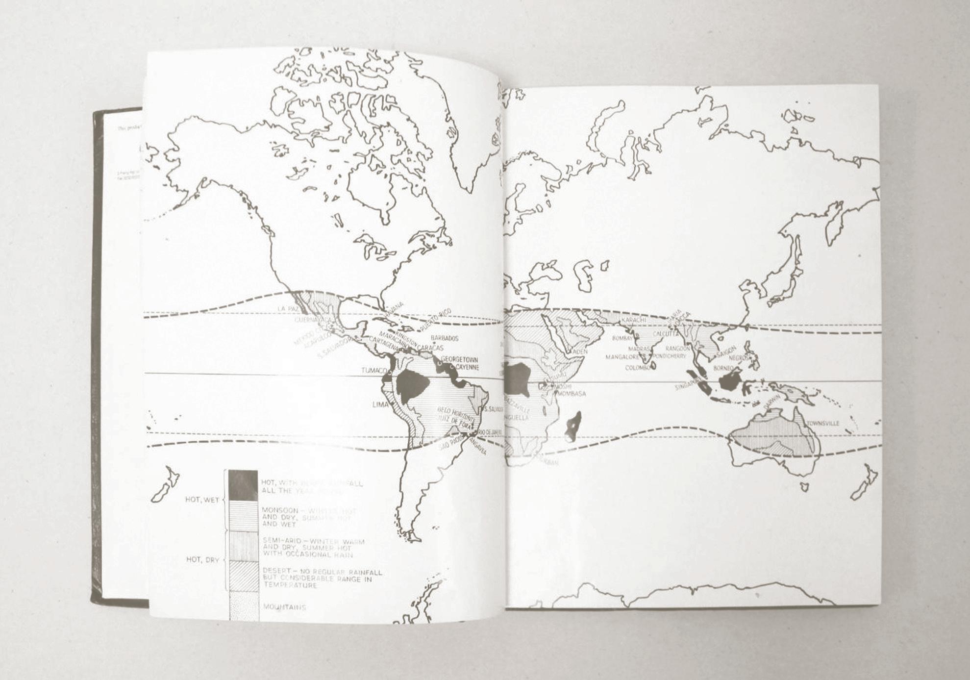
Maxwell Fry and Jane Drew stated the above as a pressing concern in 1956. Today, 60 years later, that concern has become critical. A vast majority of the world’s growing population resides in the equatorial belt, and the resulting urbanization has led to massive territorial transformation and rising temperatures. The full effect of this widespread urbanization at such rapidity and intensity is yet to be fully comprehended, but it has already altered the equator in terms of environmental degradation, massive demographic shifts accompanied by severe economic and social disruption. Entire cities and their implied ecosystems have emerged rapidly along the equator without entirely clear or articulated theoretical frameworks for why they were constructed that way. Often informal, these cities sprawl in scale, suffer from immense traffic congestions, health and sanitation challenges and drastic forms of economic disparity. From Manila to Lagos, Jakarta to Colombo, the equatorial urban context is one of “utmost gravity” requiring a serious response to architectural design innovation. Architecture in these cities often operates outside the purview of normative urban planning and zoning regulation and
in so doing, the form of individual buildings has had to adapt itself in response to its environment. Influencing factors include the harsh tropical hotness and wetness of climate along with the challenges of increased urban traffic, monsoon deluges and the congestions of mobility in the growing equatorial city. Likewise, the extreme pace of developmental pressure especially found in Southeast Asia presents a laboratory for timely architectural thinking and iteration.
“Deep Envelope, Thick Elevation, and All Things Architectural on the Equator” addresses these developmental pressures and their resultant architectural consequences at the JTC Ayer Rajah Estate within Singapore, one of the more highly planned and rationalized cities on the equator. Modernized in the 1960s and 1970s, Singapore is again retooling herself from a high-tech manufacturing and service economy to an intellectual and creative force for idea generation today through a series of nation building campaigns. The site in Singapore represents not only an aspiration for other cities along the equatorial belt, but also a narrative of reuse of existing building stock. The site is an old light industrial complex of factory buildings constructed and managed by Jurong Town Corporation (JTC), the largest industrial space developer in Singapore. The original buildings on the site, along the busy Ayer Rajah Expressway were completed in the 1970s when Singapore was in the midst of its first phase of industrial transformation. The JTC Ayer Rajah site today is a suitable petri dish study for the challenges of rapidly densifying equatorial cities due to the complex microcosm of existing programs and typologies, including multiple-use buildings, eateries, highways, housing, and an adjacent university campus. The architectural projects contained in this book offer speculative projections on the future densification and development of this site, within the hot and wet environment of Singapore. JTC currently intends to keep the existing factories, yet densify them through new “Class A” offices and research spaces, above or adjacent to the existing buildings. Retaining the existing structures is a key parameter, not only based on environmental benefits through reuse, but more importantly to use the existing urban fabric as a backbone for additional densification. Challenges relating to urban form, spatial grain, structure, climate, envelope, liveability, and creative ecosystems are tackled within the research projects presented here.
The research mines the history of architecture in the tropics to construct a novel design response specific to the highly dense, vertical city on the equator. Historically, tropical architectural discourse has centred on a series
of performative and cultural devices to modulate and mitigate heat load through breeze calibration in low-rise, low-density structures of timber or light weight masonry. The roof served in this primary capacity as thermal buffer, with the elevation as a secondary player in the form of screens or perforated envelopes. However, since the early 1950s and the advent of large scale air conditioning, architecture in the tropical zone – and likewise in Singapore – has approximated temperate architecture’s manifestations of sealed envelopes, curtain walls with minimal overhang, and the elimination of large scale roofs. Air conditioning is often presented as a technological triumph that has alleviated, by negation, the climatic conditions of the hot and wet tropics.
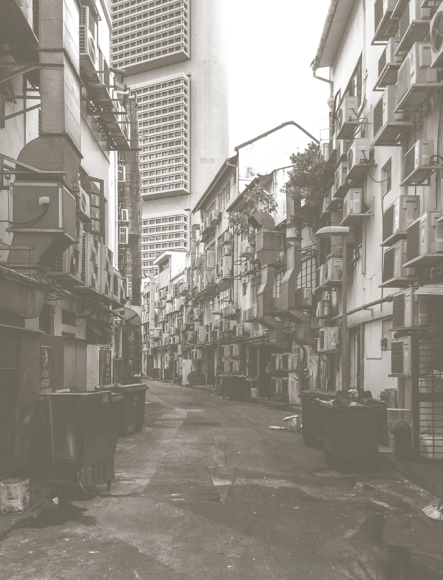
Sheathed in a glass skin to symbolize a business-friendly state, the architecture in the central business district of Singapore – like many prosperous centres found in Jakarta, Manila, or Kuala Lumpur - is located in a climate of ubiquitous heat, humidity and rain; a climate that drives people indoors rather than out, under cover rather than exposed, and towards the artificially-conditioned rather than monsoon breeze. The result is an architectural and urban scene that looks and operates with little difference from that in Shanghai, New York or London. From the 1970s to the present day, the architectural outlook of Singapore and much of the developing tropical region has been entirely dependent not merely on a system of air conditioning, glass curtain walls, and enclosed environments, but more fundamentally, on an entire mind-set of the eradication of the tropical. This is particularly apparent for larger scale developments including office complexes and retail environments.
What was once permeable for ventilation, such as colonial black and white bungalows with deep verandahs, shophouses with naturally ventilated envelopes, jack roofs and courtyards, buildings with devices such as jail walls, brise soleils and deep recesses, have been largely replaced by sealed and hermetic envelopes. Passive devices to gently modulate climate such as overhangs, high ceilings, perforated clear stories, open balconies, internal courtyards and screens, were replaced with another, starker, form of calibration: air-conditioning employing mechanical technology and cheap electrical energy.
In a somewhat retroactive manifesto, Lee Kuan Yew, the celebrated first Prime Minister of Singapore stated in 1999,“Air conditioning was a most important invention for us (Singapore), perhaps one of the signal inventions of history. It changed the nature of civilization by making development possible in the tropics... The first thing I did upon becoming Prime Minister was to install air condi-
tioners in buildings where the civil service worked. This was key to public efficiency.”
Like many developing equatorial cities, one of the aspirational goals for the Singapore nation-state was to project modernity through its crystalline architecture. This signified a material and visual celebration of technology over nature, in the embrace of industrialization and machined precision as a symbol of progress. Much of the developing equatorial region suffers from similar aspirations and in so doing, decapitates itself from its own atmospheric context. The ubiquitous embrace of the architectural language of modernism, itself a temperate construct, erases the knowledge that architecture can modulate climate as powerfully as technology, and through that modulation can embolden the experience of space and the city itself. In short, equatorial architecture has forgotten its own form of spatial and climatic agency.
Testing the polar assumptions of stereotypical plenitude and dreamy idleness of the tropical atmosphere – as found exquisitely illustrated in George Orwell’s Burmese Days- and the productive energy of the temperate climate, that to Lee Kuan Yew enables development in the tropics, the design research asks what might be an architectural expression of the tropic’s dense urban reality? Might architecture’s expression then be one that avoids the dialectical and oppositional choices of natural ventilation or air conditioning, instead merging them into an architecture that is simultaneously open and closed, tropical and comfortable, local and aspirational?
The studio works documented in this book attempts to resists climatic amnesia brought about by air conditioning and sealed building envelopes by revisiting a wonderfully rich history and vocabulary of tropical calibrated architecture in mid-century modernism.
Today, there are very real and different challenges in the urban hot and wet environment of Southeast Asia from that envisioned in the majority of tropical discourse. Dense urban environments have consumed buffering open spaces traditionally provided between buildings. Verandahs have been all but eliminated by developmental priorities of maximizing gross floor area and saleable efficiency. High plot ratios and increased building heights have displaced the architectural and climatic role of the roof overhang, and transferred that function to the elevation.
In urban Southeast Asia, the desire to curtail smell, sounds, noise, and retain privacy trump the promise of the completely ventilated project especially in the dense city centre. Likewise, the demands for density and close building proximities minimize or eliminate the overhang on buildings, as they grow increasingly higher. Here, the
primacy of the elevation takes hold. The vertical plane rather than the horizontal becomes the crucial architectural element. Unlike Tay Kheng Soon’s proposed Kampung Bugis proposal that utilizes state control through master planning to ensure high level shading, the proposals found here deploy techniques to modulate comfort on individual buildings, primarily through the elevation.
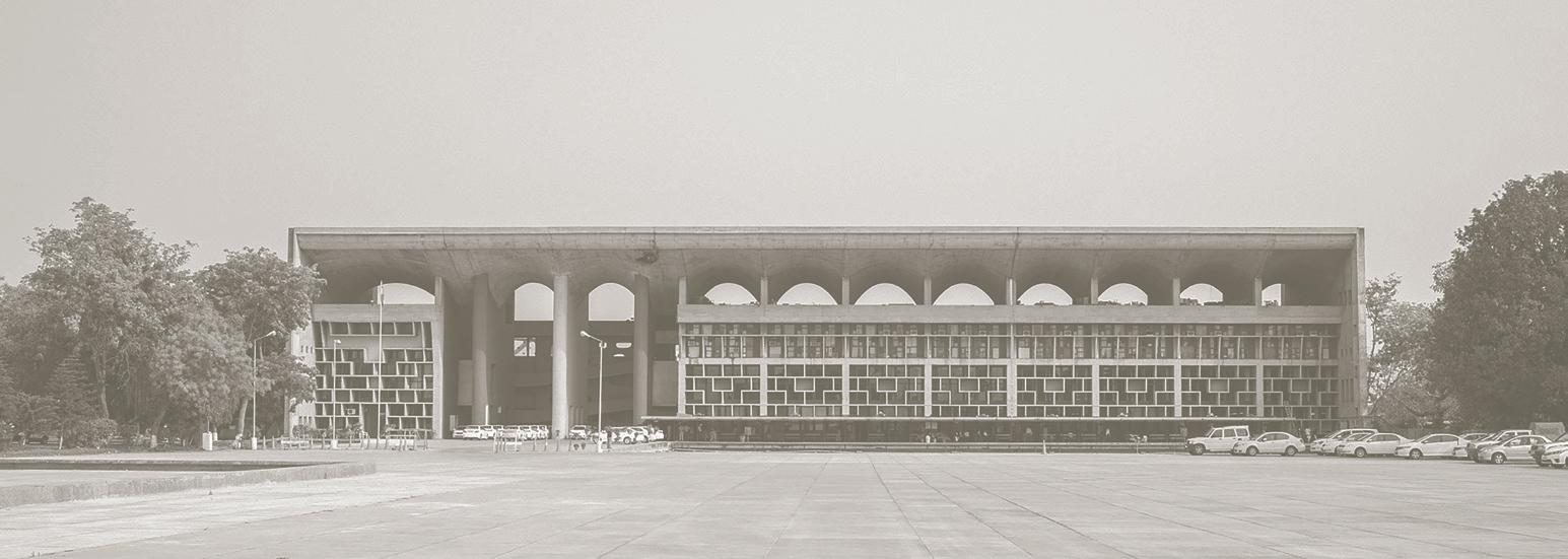
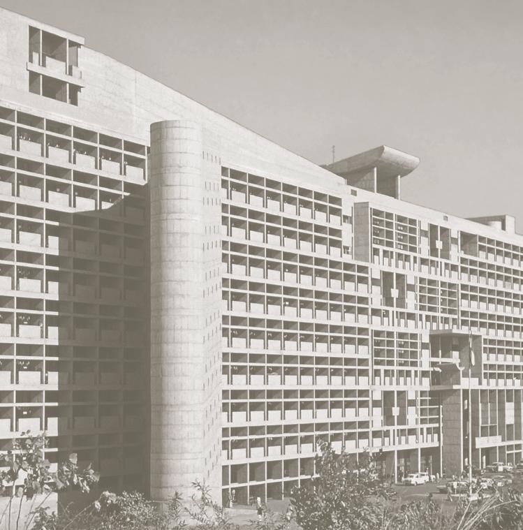
The importance of the elevation can be found in a fantastic collection of mid-century buildings that are rapidly being erased. They were produced at the advent of largescale air conditioning, where passivity and mechanical demands had equal sway, where atmospheric calibration was manifest through materials, not through mechanical conditioning alone. Lineages may be found in Singapore from the James Ferrie and Partners’ Wing On Life Building built in 1975, to the replaced AIA Building along Robinson Road by John Graham & Co. (1958), to the demolished US Embassy Building by Frederick E. Emmo & A. Quincy Jones, with James Ferrie and Partners (1961). In the general architectural discourse of the time, several buildings suggest a manner of merging environmental, structural and spatial concerns into an efficient and performative envelope. Namely, Edward Durell Stones’ US Embassy in New Delhi (1955), Vladimir Ossipoff’s IBM Building in Hawaii (1962) and the Curtis and Davis’ United Steelworkers building (albeit temperately misplaced in Pittsburgh Pennsylvania in 1963). Similarly, multiple buildings within the Asia Pacific region from as early as the 1940s provide lessons that prioritize the elevation as a site of architectural invention. The repertoire spans a variety of scales, depths and opacity: from the big heavy opaque elevation found in Leandro Locsin’s Cultural Centre of the Philippines (1969), or Hassan Vogel’s delicate Sequis Center in Jakarta (1978), to the early fantastic concrete work at the Golconde Dormitory in Pondicherry designed by architects George Nakashima and Antonin Raymond (1946). Each of these works prioritizes architecture itself as a site of technological and spatial invention that deals with the climate appropriately, effectively and poetically.
The work represents some of the finest of modern architecture along the urbanized equator, a language adapted to dense context, prioritizing shade, opacity, and materiality over transparency and dematerialization. The buildings collectively emphasize the elevation not as a thin glass-like membrane, but a thick and deep space of structure and atmosphere, climate and materiality, that modulates one’s experience of the equatorial climate inside and out. Most importantly, the architecture represents a developing aesthetic appropriate to being on the
equator often appearing heavy rather than light, thick rather than thin, and variegated rather than smooth.
If the elevation is the primary site of invention in the hot and wet tropical environment, then it is now forced to multi-task – to shade inhabitants from the sun, to drain off rainwater on its thickened surface, to ensure visibility, to create privacy, to control natural light, to offer natural ventilation and to mitigate noise.
Architectural elevations along the equator are not merely a thin surface, a fundamental feature one finds in temperate architecture. Rather, it acquires a depth in order to deal with the intricacies of climate, and a rich host of functions described above. Materially, it extends from the external landscape to a typical horizontal depth of 1.5 to 3.0 metres of a building. It is this depth that drives the research of this book, expanding and attenuating the deep elevation as a fundamental equatorial type in architecture. For example, verandahs and balconies are volumetric elevations that buffer living quarters and spaces of inhabitation against heat and rain. Accompanied with screens, rattan shades or louvred shutters, these spacious envelopes take advantage of the climatic condition to ventilate and provide privacy through controlled visibility to the surroundings.
In this context, a deep elevation is proposed as a key approach to modulate exteriors and interiors of buildings in the hot and wet tropical environment. A deep elevation is a spatial, thick and deep screen that is transformed into an occupiable space or enclosure, composed of opaque materials that are perforated, layered, extruded and stacked, to produce degrees of atmospheric permeability and to positively enrich the aesthetics, performance, and experience of buildings.
In equatorial architecture, the envelope extends throughout the built structure, both on the exterior and interior. When combined with structural and performative concerns, the hot and wet elevation represents an increasingly important site for research. The students of the National University of Singapore (NUS) Department of Architecture deployed the use of ‘deep elevation’ as an approach to embed a series of demands into a thickened space. This book focuses on five such projects unified in a larger vision plan for the Ayer Rajah Estate. Each building proposed utilizes a variant of a deep structural elevation. From one covered in thickened vegetation, to a structural diagrid and sunshade, to a verandah cum acoustic baffle, each architectural project learns from the past while projecting new futures for the JTC Ayer Rajah Estate.
Context and Methodologies Context
The architecture of industrial buildings located in the hot and wet climate of Singapore proposes unique challenges to architecture design at two scales: district and object building. These two scales are highly interrelated both as sites of techno-centric knowledge related to increased performance, such as minimizing heat island effect, improving wind channelling interrelationships, improving solar shading between and among buildings, as well as extending a long history of architecture and climatically responsive approaches related to elevation including structure, operability, performance, and inhabitation. The design work documented within this book mines the past to project the future. The architectural project is three-fold: selected case studies, contextual site research and architectural projections.
1. Investigation of 5 canonical Hot, Wet & Breezy buildings serves as a basis for architectural knowledge production and discourse development. The case studies are: Wing of Life Building by James Ferrie and Partners, Perpetual Saving and Loan by Edward Durrell Stone, IBM Building by Vladimir Ossipoff, American Cement Building by Daniel Mann Johnson and Mendenhall (DMJM) and Kandalama Hotel by Geoffrey Bawa.
2. The contextual boundary of the Ayer Rajah Industrial Estate stretches along the highway of Ayer Rajah Flyover, with its northern end opposite Fusionopolis and one-north MRT station, and its southern end connected underground to Kent Ridge MRT station. The site was demarcated into 5 plots, with Plot 1 as Block 47 and 51, Plot 2 as Block 55, Plot 3 as Block 67, Plot 4 as Block 71 and Plot 5 as Block 79. The district scale of Ayer Rajah provides a context to study the effects of heat island, thermal comfort, pollution, water runoff and natural ecosystems impacting land intensification and increasing density. Specific attention is applied to the district integration with the surrounding natural and liveable areas by dissolving the current sharp edge boundary through land-use diversification and circulation. District wide surveys, urban site and climatic analysis were carried out to study the district potentials and challenges to develop an equatorial vision plan.
a means to calibrate climate to industrial form in various structural solutions including reinforced concrete, EIFS and SIP (Exterior Insulation Finishing Systems and Structural Insulated Panels).
Methodologies
1. The design research utilized a series of investigative and forensic approaches to research the precedent work including collating existing historical drawings and images, studying the history and design intent of the selected buildings, understanding the personal histories of the architect and architectural
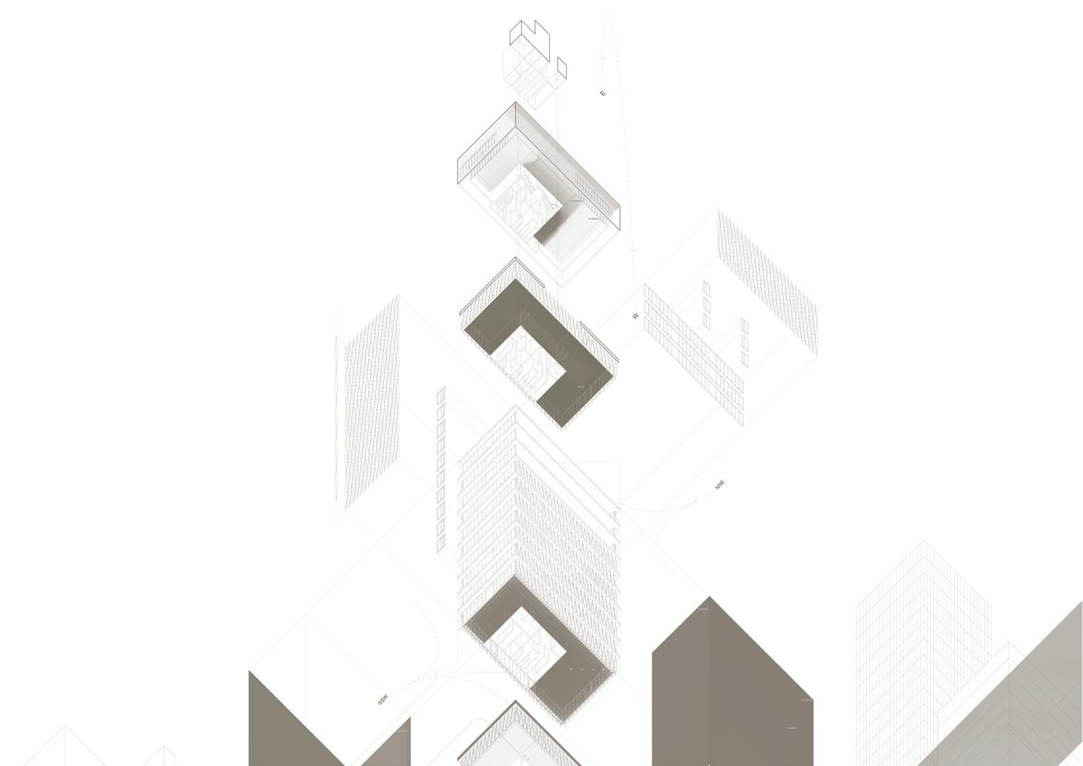
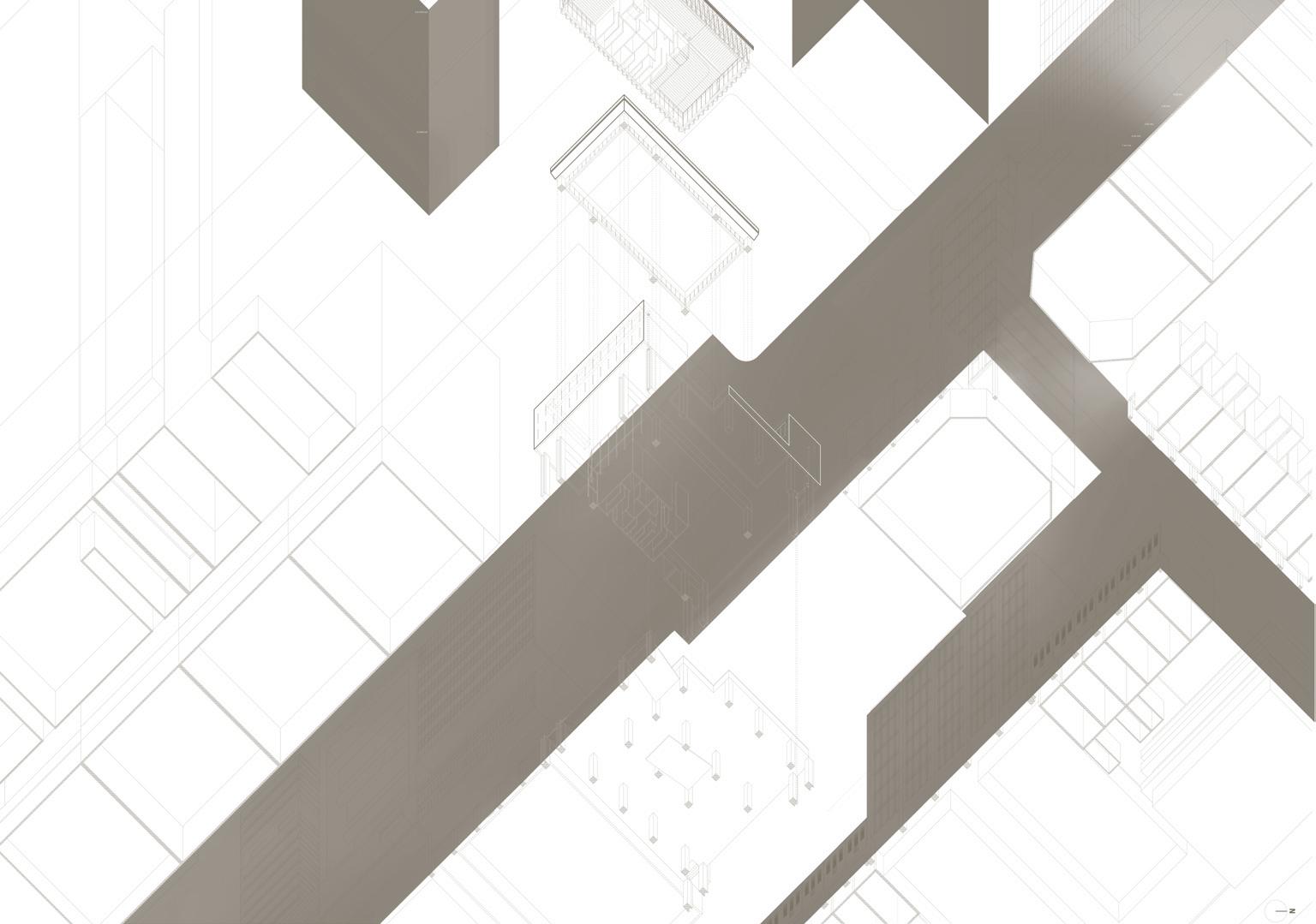
practice as well as uncovering original drawings and photographs of the completed projects. The architectural information was transformed into 3D Digital and analogue models that were then tested through Autodesk Ecotect and Autodesk Vasari to analyse sun insolation and wind flow of the buildings in relation to their site context. The outcomes were synthesized in worm’s-eye exploded axonometric drawings of the case study buildings, incorporating digital simulations of solar insolation and breeze.
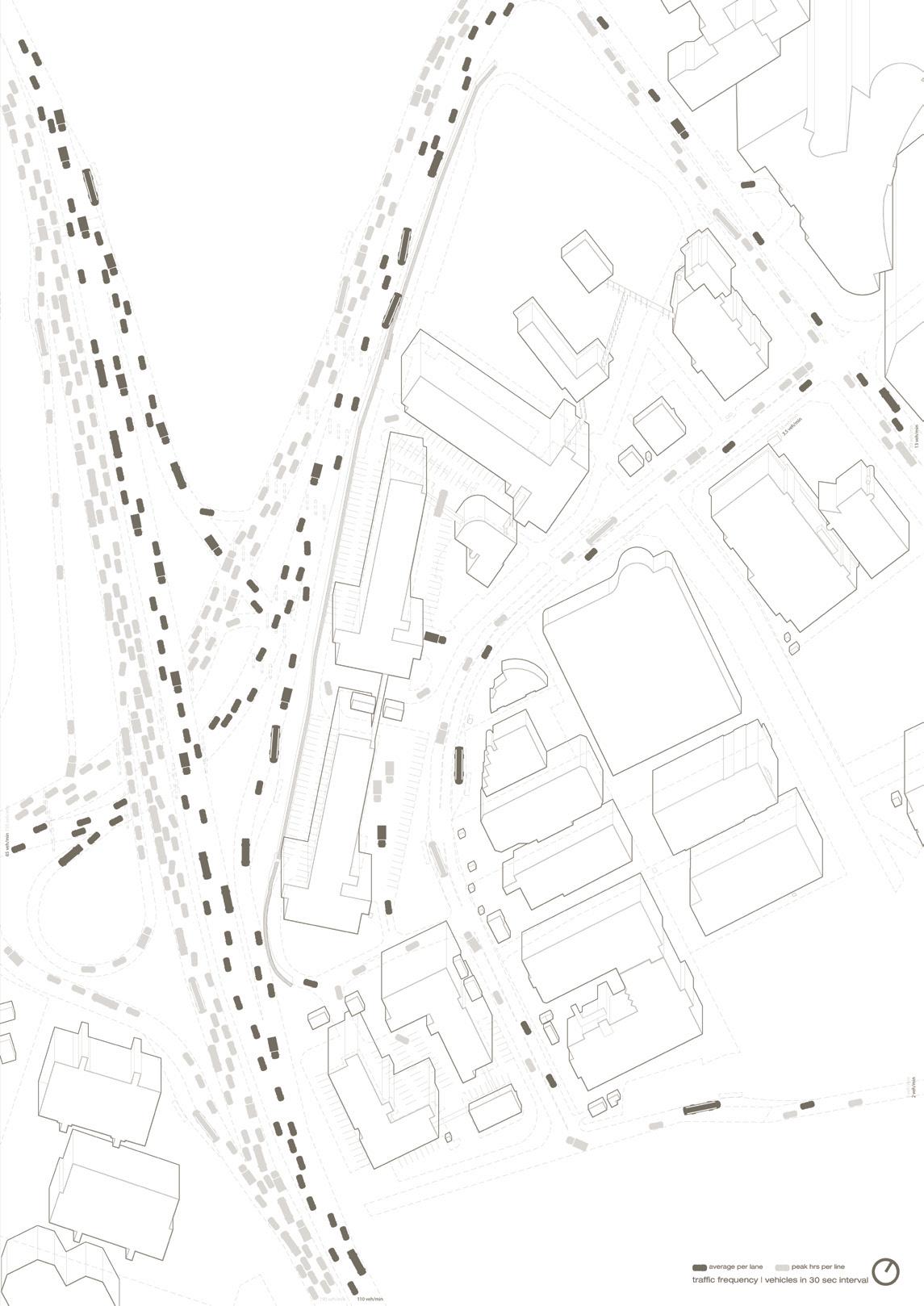
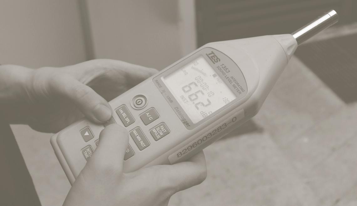
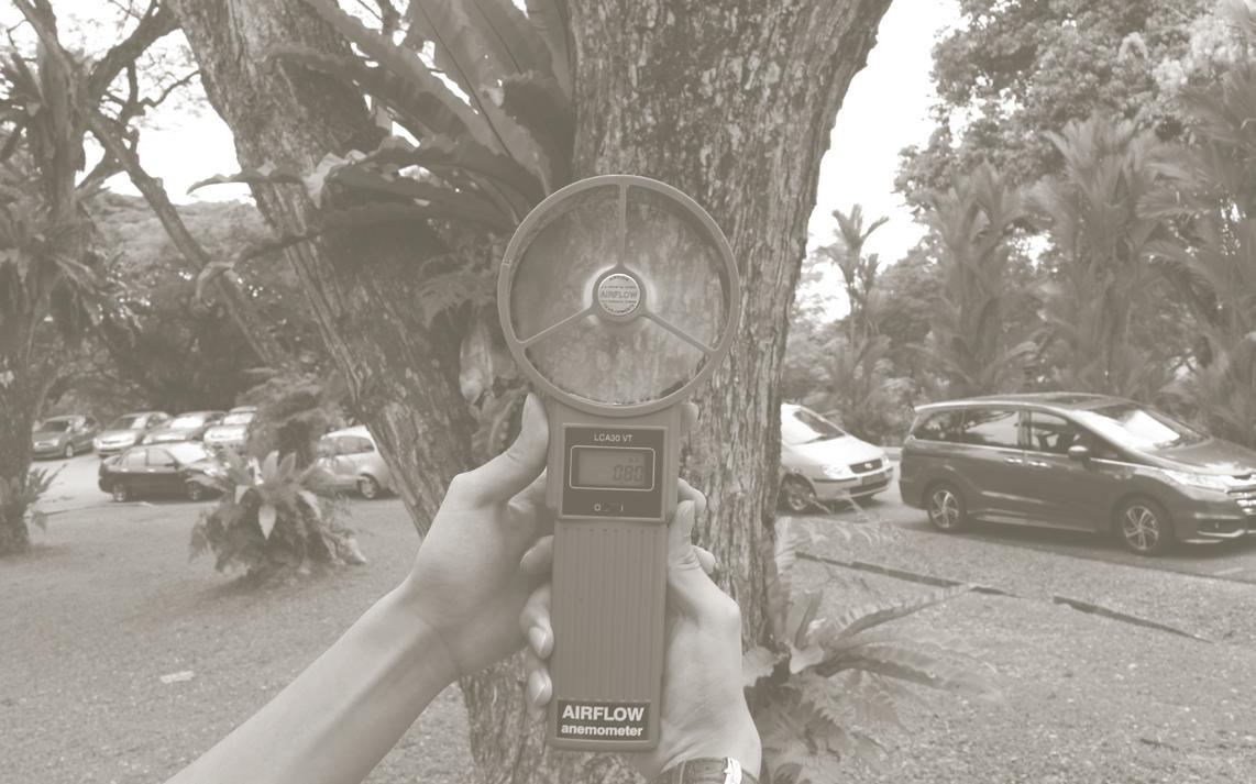
2. Ayer Rajah Industrial Estate was studied for climatic and environmental attributes including shadows, solar insolation, wind, acoustics, traffic, rain, drainage and programme. The outcomes were manifested in a series of drawing and simulations to illustrate and make visible sun exposure, wind conditions, rain intrusion, and sound. These digital simulations were compared to on site measurements with analogue apparatuses such as hand-held wind meter and sound-level meter (Figure 3). The analogue data is deployed to confirm or refute the data produced through digital simulation. Often, the analogue information proved more accurate and in line with site observations.
3. The design iterations at the scale of architecture were developed through large-scale physical models as a primary tool of research. Digital models allowed for simulation and visualization, while 3D printed and laser engraved analogue models provided material manifestations for discussion and observation. Photography of the physical models was compared with digital simulations, and feedback on the performance of the sun-shading effect and a sense of the atmosphere were verified through the physical and spatial qualities manifest in the analogue models. This method produces immediate feedback on the design and overcomes the limitations of long hours needed for digital simulations to act on more complicated designs approaches. Digital fabrication equipment was heavily utilised in the model making process. 3D printers are useful in producing models that involve 3D curve geometry while laser engraver machines were effective in producing small, intricate and repetitive parts that are used in the large physical models. The 3D printers used were Formiga P100 and Makerbot Replicator 2 while the laser engravers machines used were Epilog Legend 36EXT.
The original planning of the Ayer Rajah Industrial Estate was based on a series of simple modernist principles largely based on function, ease of mobility access, and efficiencies of construction. Minimal design attention was paid to the urban quality of the district, built at a time when industrialization trumped urban amenity. The district today is an agglomeration of flatted factories and dense mid-rise towers, fabricated in concrete with perimeter circulation verandahs and naturally ventilated lift lobbies. A series of parking lots and ring roads surround the estate effectively cutting off the buildings from the larger context except through the use of automobiles and small-scale trucks or lorries.
Flanked by two existing Mass Rapid Transit (MRT) stations, namely Kent Ridge Station and one-north Station, to the south and north respectively, the site and its proposed future development is envisioned as a ground for emerging start-up offices of various disciplines related to a technology driven maker culture. This is a radically new programmatic vision for the original buildings that requires a serious rethink of the urban quality and amenities required to facilitate contemporary industries and their employees. The proximity to the bio-tech hub of One North to the North, the media centric facilities of Mediacorp to the East and the technology and educational facilities of Science Park 1 and the National University of Singapore to the South suggest the potential for the site to be a vibrant and exciting neighbourhood, not simply an industrial landscape upgraded by new technology. The amalgamation between the current factory typology and the proposed interventions is proposed to cater to a series of important contemporary working and interaction conditions to create a successful technology and small scale maker ecosystem.
The concept plan as proposed by JTC includes the construction of sky bridges for connectivity across the various buildings of the estate. However, instead of a single route sky bridge connection, the proposed research and design direction here advocates a variegated ground floor open to the public and filled with small scale shops, restaurants, and retail and fine-grained commercial environments linked by a series of courtyards. The ambition is to intensify the ground plane and link the public space of the development into the larger framework of mass rapid transport and surrounding buildings.
This proposal rejects the linked sky bridge approach proposed by JTC. This is because numerous historical examples suggest that sky bridges and upper level inter-
connectors decrease the intensity and quality of life at the ground plane by diverting traffic and people flow to numerous points across the section of the urban estate. By doing so, the dispersed circulation through vertical stratification often diminishes the intensity of development precisely on the ground. This proposal works to intensify and amplify the ground plane by making this space the most important connective tissue across the development, not through decongestion and separation, but through carefully applied pedestrian congestions and frictions defined by the architecture. Lively experiences associated with “being on the street” gains animation through chance encounters, people watching, café culture and contemporary ad-hoc workspaces enabled by the overall urban plan.
Zoning Parameters and Drivers:
1. In accordance with URA (Urban Redevelopment Authority) 60:40 rule, the proposed development ensures that:
i) At least 60% of the gross floor area is to be used only for industrial activities, illustrated by manufacturing, assembly, R&D, ancillary storage and ancillary warehousing
ii) The remaining 40% of the gross floor area may be used as ancillary offices, showrooms, neutral area and communal facilities.
2. GnPR is defined as the ‘average leaf are index (LAI) of the greenery of a site”. NParks defines GnPR as ‘the area weighted average leaf area index of a site’2: Optimal GNPR for Industrial is 0.6 to 1.4 and 150% Green Plot Area.
3. 25% Ground Floor Area for ancillary uses.
Unit size (Block 71) – 100 sqm
Unit size (Block 73) – 20 or 40 sqm
Unit size (Block 79) – 100 and 450 sqm
TOTAL SITE AREA = 100 440 sqm
TOTAL ANCILLARY AREA = 3 273 sqm
TOTAL BUILT UP (INDUSTRIES) AREA = 121 517 sqm
Taking into account the abovementioned regulations, the research aimed to intensify the land use to a distributed plot ratio of 4.0 across the entire development. Specific plots have increased or reduced plot ratios to inform a topography skyline in line with the existing Zaha Hadid plan, though in aggregate the plot ration of 4 is achieved.
Vision Plan
The courtyard, traditionally, directs light and breeze into a deep floor plan. Combined with supporting climatic data the urban courtyard is deployed strategically in response to urban flows, circulation, ventilation, shade
and protection from monsoon rain. The collective ground floor for these courtyard spaces are designed with different qualities- from a lush garden, narrow tapering courtyard, and canopy to atrium. On the urban scale, the courtyard allows construction of individual buildings to systematically and in isolation from one another. This phased approach focuses construction noise to limited areas across the site, rather than causing disruption throughout the site.
Being the leading points towards the rest of the industrial estate at the North and South elevations respectively, Plot 1 and Plot 5 are tallest in height at 80 metres with 20-storeys each, matching the height of tall neighbouring buildings. The massing of the building decreases in height gradually as it approaches the middle of the side. The lowest points in the massing are 7-stories (35m) in height, are located at Plot 2 and Plot 3. This depression produces a curved profile both in section and in plan creating a dramatic urban form while gracefully linking the increased densities about the sites perimeter.
Parking is minimized across the site in anticipation of a “Car Lite” future in Singapore or with the advent of new driving technologies being developed by Uber and Google. Two small scale parking garages are excavated into the ground between Blocks 67 and 71 as well as between 51 and 55. This frees up the ground plane for pedestrian activities.
Elevation strategies
The architectural elevation becomes a primary site not only to satisfy a series of environmental demands but also to provide a structural solution for increased development on top of the existing buildings. Each proposal reaches a compromise between their performative tasks - shade, drain, ventilate and support.
Research Outcomes
Responding to various site conditions in terms of solar insolation, wind, acoustics, traffic, drainage issues, existing buildings, and programme, each plot was designed with a distinctive design proposal adhering to the guidelines of the proposed urban plan. A summary of design direction of each proposal is given below, while the narrative, drawings and visualisations of the proposed designs are found in the following chapters.
Plot 1 (Block 47 & 51)
Two existing L-shaped blocks frame a natural open space with two entrances flanking the National University of Singapore (NUS) and the extended industrial development to the east of the estate. Approaching the site through an underpass from Kent Ridge station from NUS, pedestrians first enter the estate with a gentle slope towards the centre courtyard. All three proposals instinctively utilise the envelope as a structural veil to cantilever additional floor plates above the existing blocks. Doing so unifies the existing buildings and aggregates them into a larger complex. Structural demands dictate the geometry, though the simple massing and platonic form anchor the development in a large-scale building block. Specific approaches to the envelopes seek to mitigate sun load and noise transmission from the adjacent expressway, as well as minimize air-conditioned energy usage.
Plot 2 (Block 55)
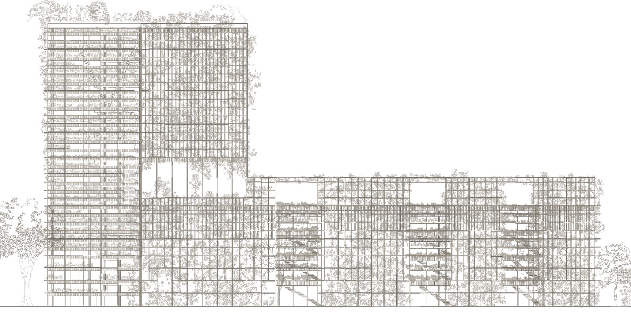
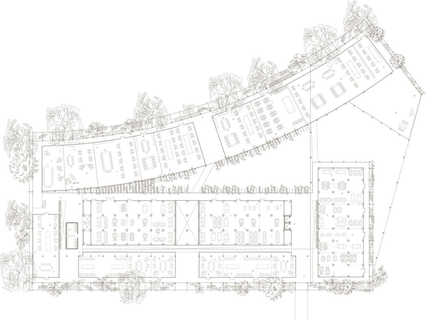
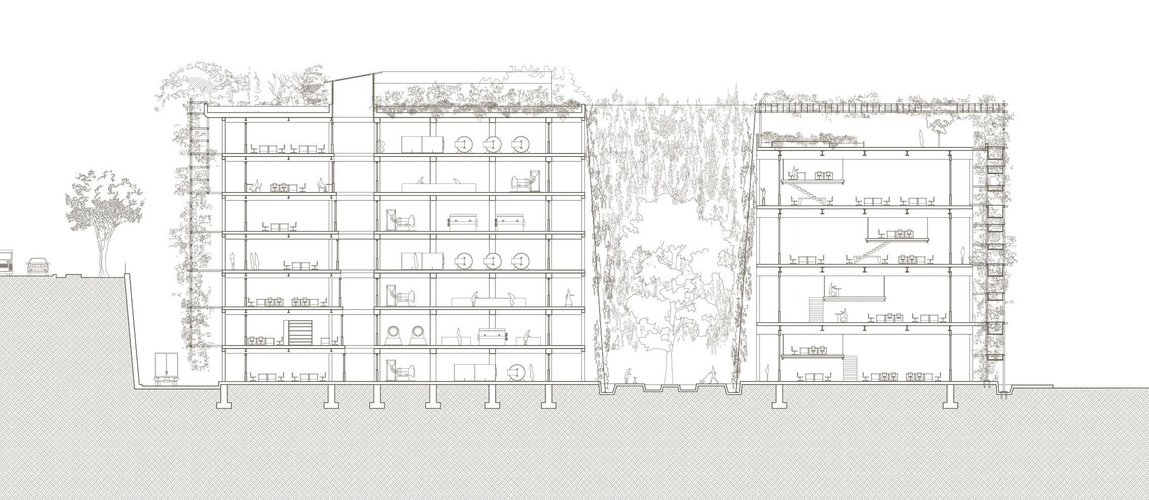
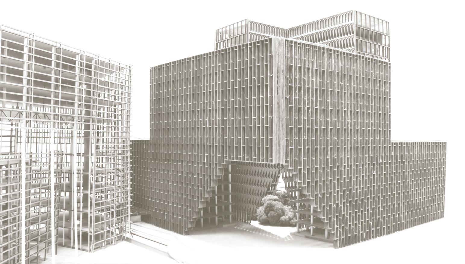
Adjacent to Plot 1’s northern face is a T-shaped office block, Block 55. The proposal adds a new block in the existing parking lot, accommodating new floor area while minimizing the need for complex structural techniques to span over existing buildings. An architectural contrast between the original building and new proposed architecture articulates spaces for two modes of working: small-scale maker and digital fabrication companies are proposed to occupy the existing buildings, while Class A office space for companies requiring a corporate culture and office based identity are found in the newly proposed additions. The two buildings are separated by a narrow triangular courtyard, tapering northward. Tropical vegetation across the envelope address fluctuating weather conditions on the equator while providing a green lung for the development. Deliberate choice of plants, canopy diameter, density are crucial design considerations for the ‘unfolding’ of the green facade over time, allowing it to change in colour across the various monsoon and dry seasons. Organisation of landscape demarcates the exterior and the interior; it shades inhabitants from direct sunlight, provides privacy from neighbouring blocks and directs rainfall towards the growth of the plants. More details for this proposal can be found in Chapter 4.
Plot 3 (Block 67)
Block 67 is situated within a narrow site between Ayer Rajah Expressway (AYE) and Ayer Rajah Crescent. Due to
its geographical location in close proximity to the heavy traffic at the intersection and traffic light to the on ramp of the AYE, traffic pollution is the primary parameter to calibrate a modular system capable of handling poor air quality, thermal load and wind driven rainfall from the southwest monsoon. The depth of each module is calculated numerically in accordance to the direction of tropical weather components to effectively mitigate heat, rain and daylight, offering a proposal with both atmospheric interior and aesthetically functional exterior. Subtle variations in the envelope can be found along the repetitions. Details for this proposal are discussed in Chapter 3.
Plot 4 (Block 71)
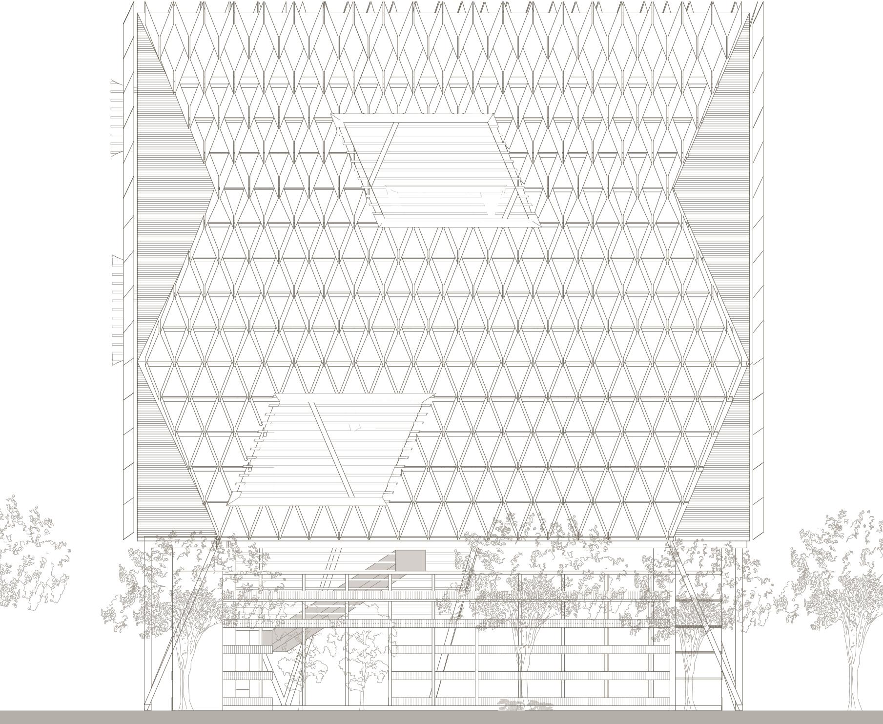
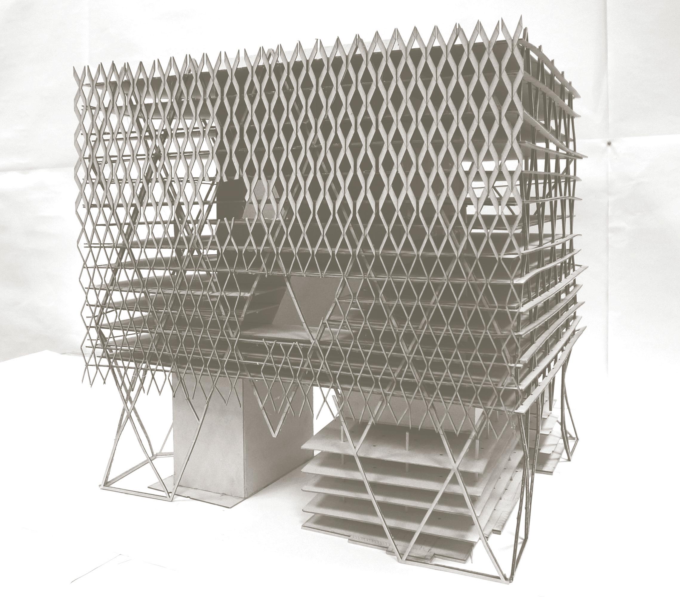
Akin to Block 55 and 67, the T-shaped office block expands upwards due to narrow site. The new volume is held up by its diagrid structural envelope and hovers on top of the existing structure. Monsoon rain becomes the primary climatic concern as the long elevations are orientated in north-north-east and south-south-west directions. Structural demands to contain the large floor plates above the existing structure require a substantial diagrid structural solution. The mutated veil encircles the circumference building in the manner of drapery in response to demands of structure, climate and site. The envelope unfolds itself on the South elevation to a sheltered canopy connected to neighbouring building, to strengthen an urban courtyard on its North elevation and bends open to allow porosity of circulation and interconnectivity to the adjacent blocks. Design details are elaborated in Chapter 3.
Plot 5 (Block 75)
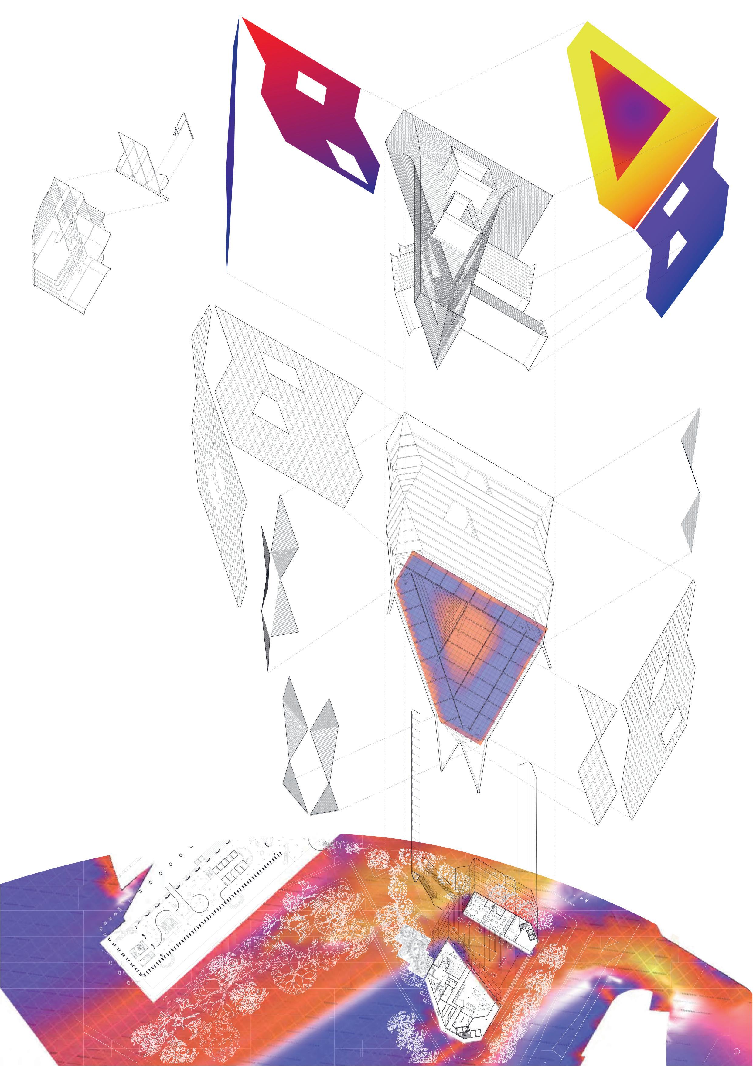
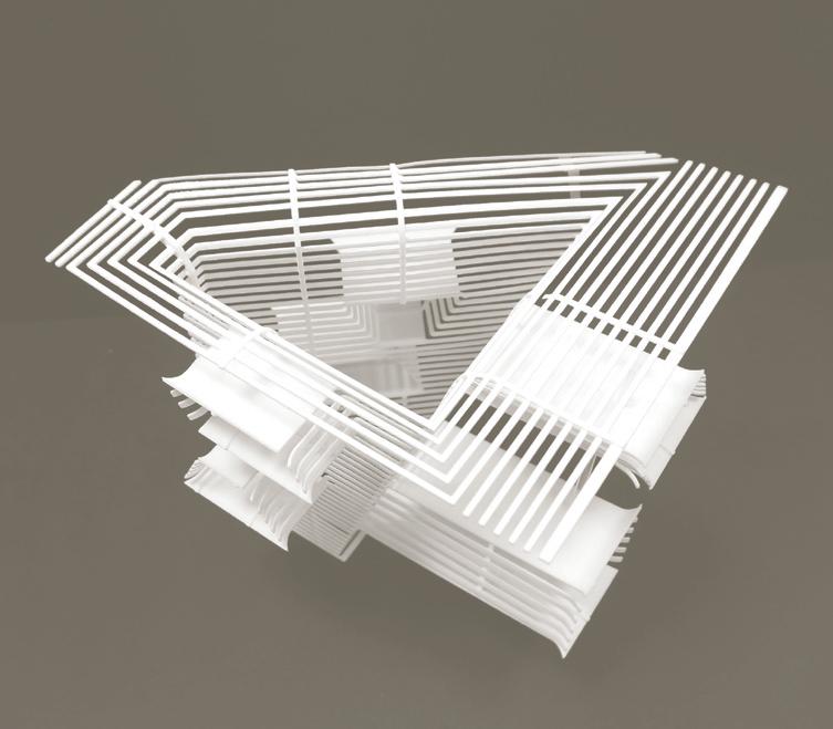
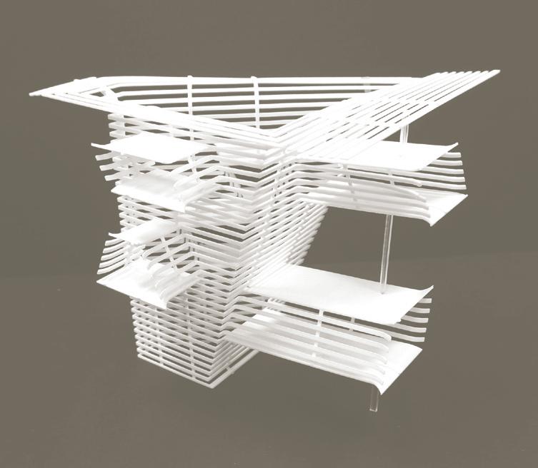
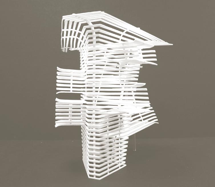
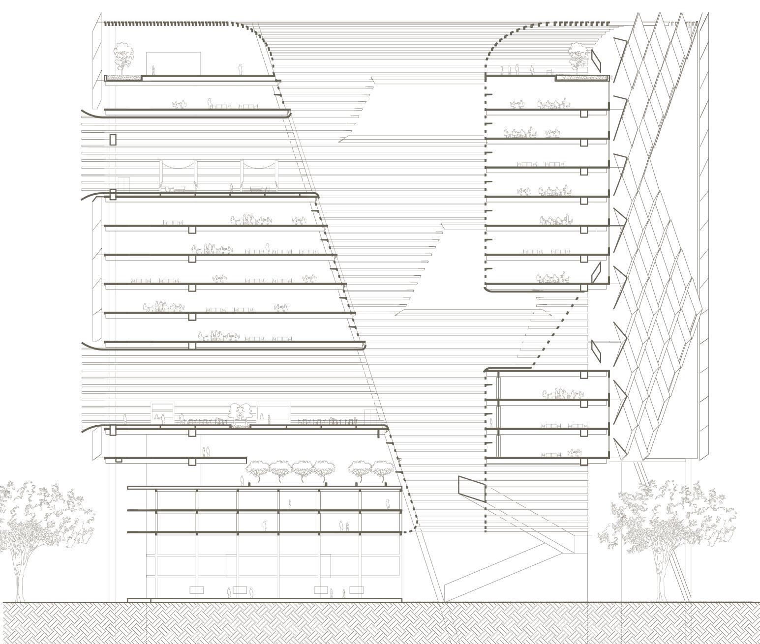
Positioned at the opposing end of the Ayer Rajah Industrial estate, Block 75 serves as a portal for pedestrians from Fusionopolis to traverse to the one-north Station through the estate. A simple existing building mass is added to by a large-scale development above. A triangulated tripod-like structural system traverses the spanning requirements and locks the development into place, allowing for an addition of 20 stories on top of the existing building. The unification of the existing and new is not solely achieved through exterior envelope, but also via the positions of the vertical central courtyard and numerous punctuated horizontal voids. Because of the site’s triangular form, three facades compose the majority of the building while the Tripod diagrid structure informs the geometric pattern on the exterior. The internal courtyard facade, made up of delicate horizontal louvres, extends
into the internal surfaces of the voids which cross-ventilate air. This project is elaborated in Chapter 1.
Land intensification coupled with the retaining of the existing flatted factories drove the overall massing direction of the estate, while catering to a diverse body of mature corporations and young start-ups. Structural design was incorporated into the design ambitions of the envelope incorporating load bearing functions in addition to atmospheric calibration predicated not only on performance but also on contributing a new holistic approach to architecture of the tropics, emphasizing light weight, materially efficient approaches to tropical elevations. The research outcomes aimed to be applicable not only to the Ayer Rajah area but throughout the industrial landscapes managed by JTC across Singapore.
Reflections
Challenges in the design iteration process remain, Firstly, the production method of 3D printing is still time consuming and remains costly. With fixed number of 3D printing facilities in the studio workshop shared by two faculties at the Department of Architecture at the National University of Singapore, only a few models could be printed at a time. The production time was largely dependent on the length of waiting list as these resources are also shared with a Department of 700 students and researchers. However, this is a short-term obstacle that would be eradicated as 3D printing becomes more accessible and affordable.
Secondly, constrained processing and simulation software remains time intensive and limit the design feedback loop from ideation to simulation to design resolution. Research could study the climatic condition on site using highly crude approximations, before proceeding to the next stage of design. Wind simulations take approximately two weeks and proved highly cumbersome for a fast moving design process. Therefore, it was unfeasible to simulate the various extreme weathers during the monsoon seasons. The research also relied heavily on site analogue techniques. These proved highly necessary and relevant in the design process, to test and make visible errors in the digital simulations. Often, simulations differed in great deal from on-site experience. Without site data, the research could only rely on digital simulations as a source of reference for design iteration, with limited means to verify its accuracy.
Thirdly, structural simulations and verifiable results were tested only at the concept design stage. The research would have been strengthened by more structural
engineering input, however, the demands of the research studio from vision planning to detail execution proved challenging for a 13 week research design studio.
Lastly, certain climatic attributes lack source information and conventional mode of documentation. For example, researchers were not successful in retrieving comprehensive information of the impact of rain from NEA (National Environmental Agency) or from digital simulations. On top of the volatile volume of rainfall every year, the impact of rain onto building surfaces are difficult to measure due to complexity in variables including wind speed, wind direction, droplet size and morphology of surrounding buildings. Therefore, the research could only rely on the rules of thumb that the depth of rain splash is half of the opening height.
Conclusion
Modern architecture’s relationship with the equatorial atmosphere is a conflicted one. From the spatial brise soleil’s of Le Corbusier to the culturally specific work of Geoffrey Bawa, modernism has sought to reconcile the demands of the growing urban city and its vertical aspirations, the interweaving of technological innovation (air conditioning, lighting, energy) with the distinct climatic experience of site, as well as cultural and economic individualities found along the equator with the overarching industrial and capital systems that lean toward totalizing systems. Specifically, technology and air conditioning has been used to compress notions of comfort into standardized temperature and humidity controls, erasing the agency of architecture to construct diverse and powerful experiences. Along the equator, such a challenge becomes increasingly important, as comfort through technology and architecture collide, the results are the ubiquity of the glass curtain wall tower, uniform ceiling heights, generic floor plates and hermetic environments sealed off from the tropical environment, differentiated only by slighting façade pattern play or skewed building massing and crowns.
The work in this book attempts to resist this diminished role of architecture on the equator by merging the conflicts of urbanization, technology, and architecture into a coherent aesthetic that is open and closed, tropical and comfortable, local and aspirational. Most importantly, the design work shown within this book attempts to resist atmospheric singularity by creating a more nuanced relationship with climate and space. By mining the rich and long history of tropical architecture, the work learns from the past while projecting new architectural formations
that are climatically and contextually specific. Through representational techniques and design iterations, the work constructs an aesthetic language of a dense urban equatorial future, relevant to the atmospheric realities of living and working in Singapore.
Typologically, two areas posit important outcomes of the research. Firstly, the elevation is the primary site of architectural innovation in the tropics, as a deep surface that modulates interior and exterior, comfort and circulation, structure and skin. The work shown within this book utilizes material and structural depth to empower architecture to construct atmosphere related to its hot, wet and breezy context, in opposition to the hermetic tendencies of air conditioning. It is within this depth that a variety of spatial, atmospheric and structural environments are created, resisting the climatic amnesia that air conditioning so often brings to architectural formation found in Singapore (and generally in many rapidly modernizing cities throughout Southeast Asia).
The second outcome is specific to the urban configuration of shaded courtyards, vegetated ground planes and terraces, and the continuity of pedestrian movement and articulated congestions. Air conditioning is embraced as the climatic norm in Singapore, although being outside under the shade is just as comfortable when calibrated to the monsoon breeze. The work seeks to empower this outdoor climatic space, not merely to fulfil notions of sustainable energy use, but to experientially redefine the norm by imagining a series of exterior spaces that engage the senses and create a lively and diverse ecosystem for the district’s inhabitants.
This complex outdoor environment suggests a way of equatorial inhabitation that is pedestrian-centric – in direct contrast to the automobile centricity that has driven the majority of Singapore’s urban plan. The research reasserts the importance of simple yet important urban qualities at the pedestrian scale as the foundation for a successful urban plan. The proposals trace an imagined ecosystem of pedestrian use combined with the diversity of inhabitation on the ground plane.
Although not exhaustive, these studies and design projections afford a clearer sense of what a dense equatorial city could be: a city between the inside and outside, a city between congestion and pedestrian interaction, a city between the dense and the vertical. Most pertinently, the ideas produce a city that can only be found on the hot, wet and breezy equator.


Bibliography
D. (n.d.). To Develop Landscape Guidelines for Application of Green Plot Ratio in Singapore. Retrieved June 06, 2016, from http://www.sde. nus.edu.sg/csac/r9.html
New Perspectives Quarterly, Volume 26 #4/ Volume 27 #1 Fall 2009/Winter 2012 “The East Asian Way–With Air Conditioning” Interview between Nathan Fardels and Lee Kuan Yew in 1999. Accessed on October 22, 2012

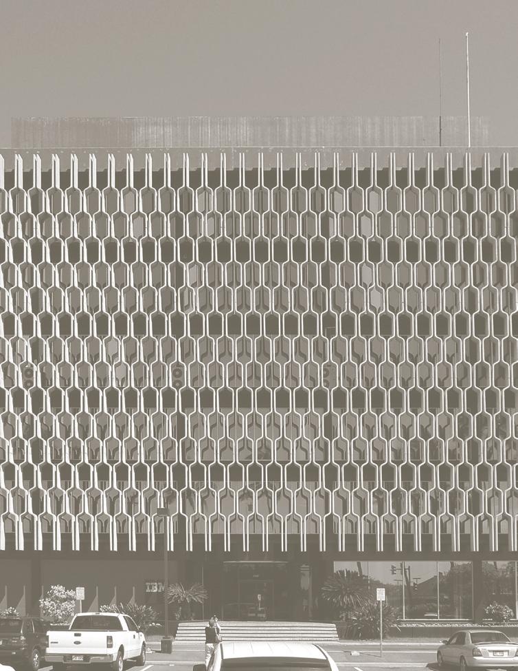
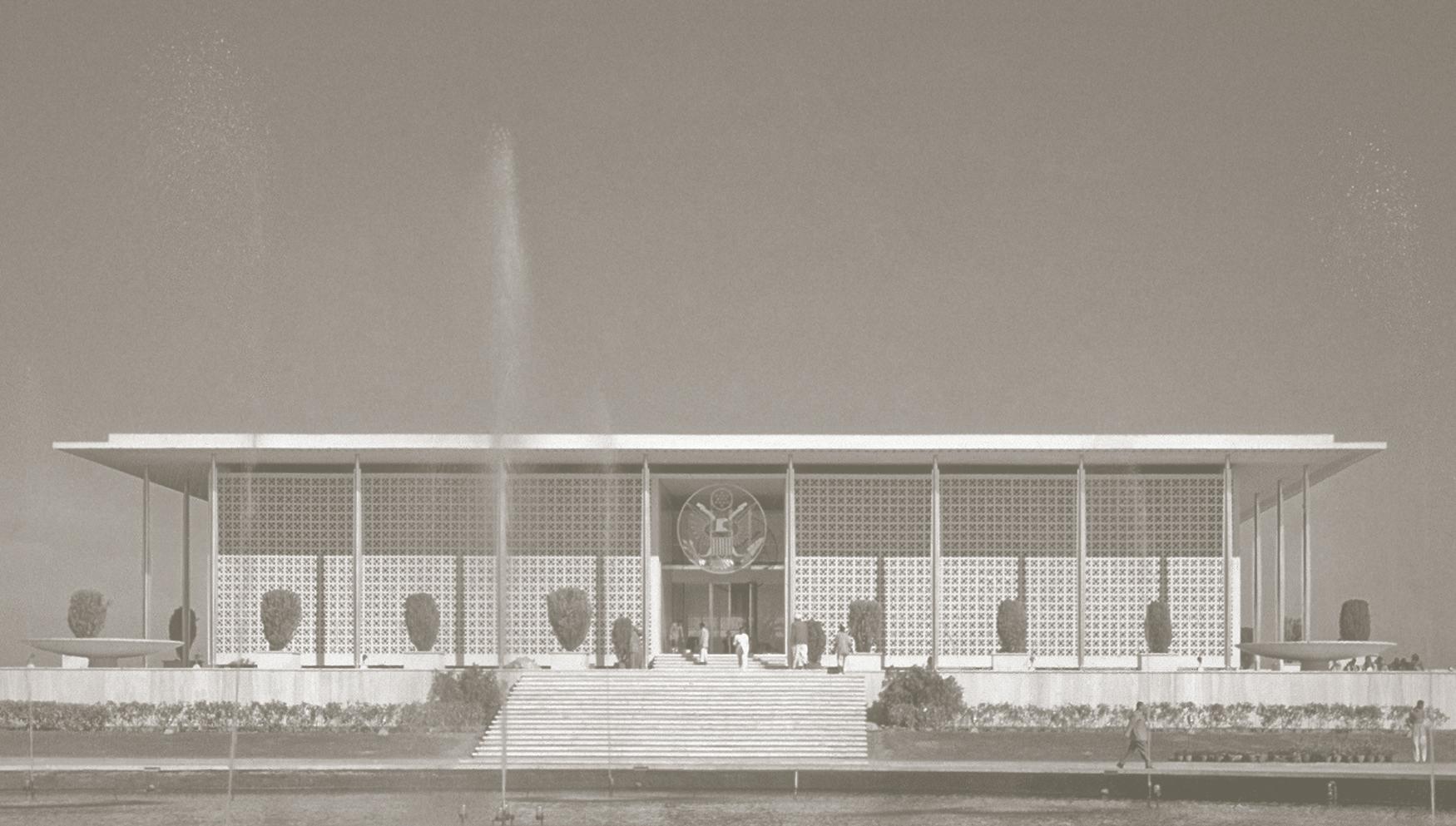
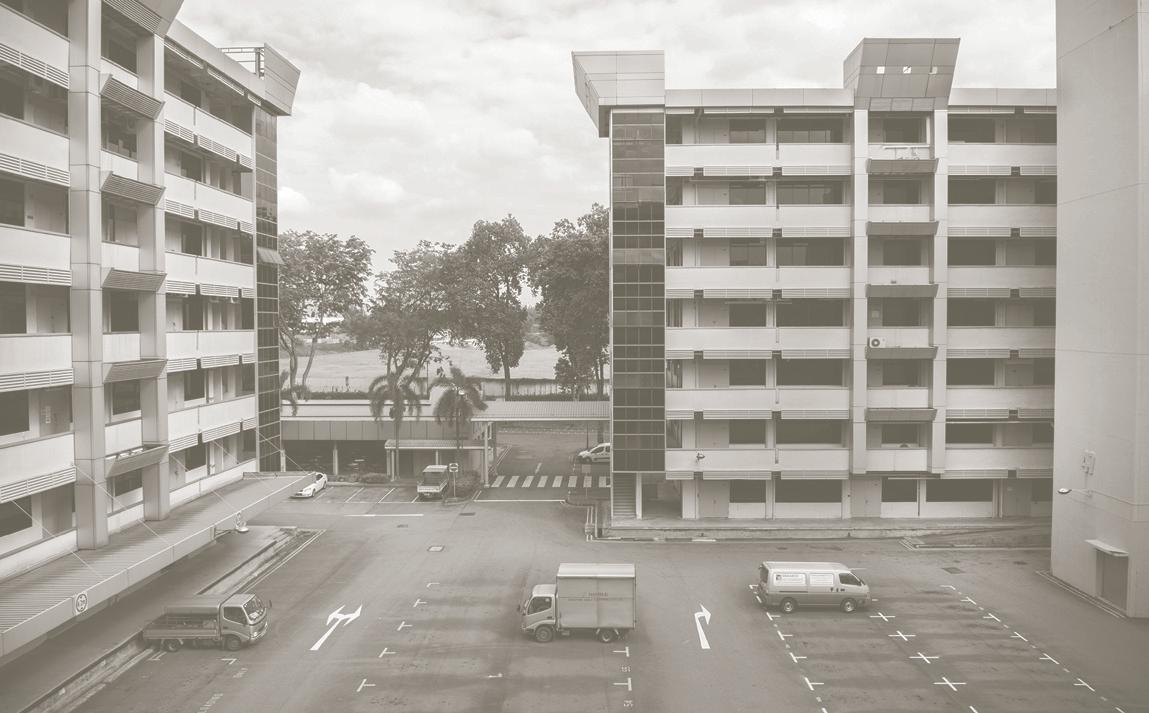
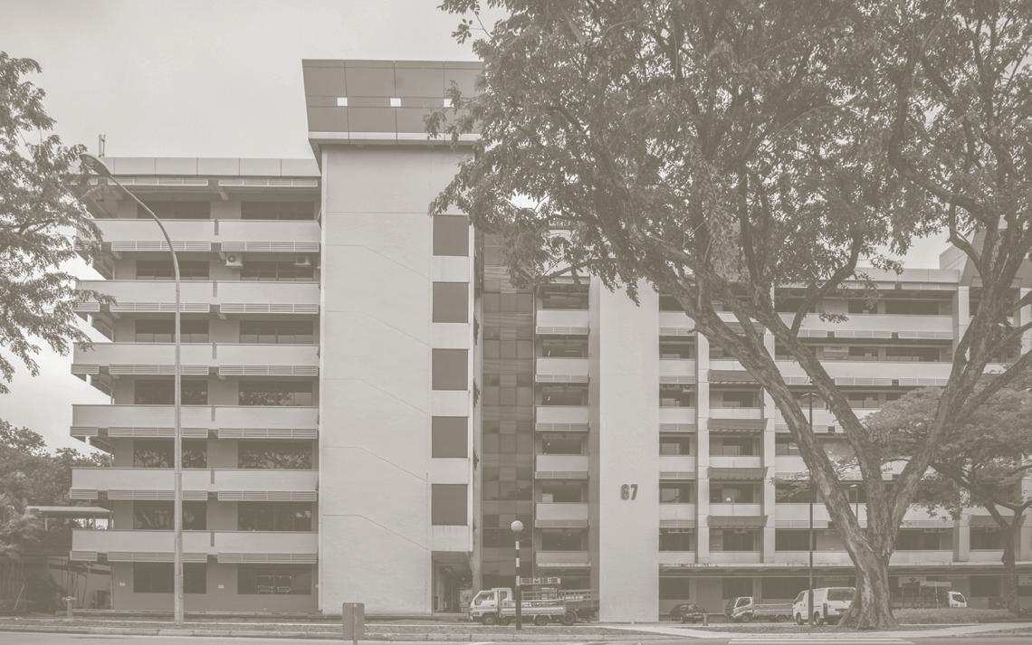
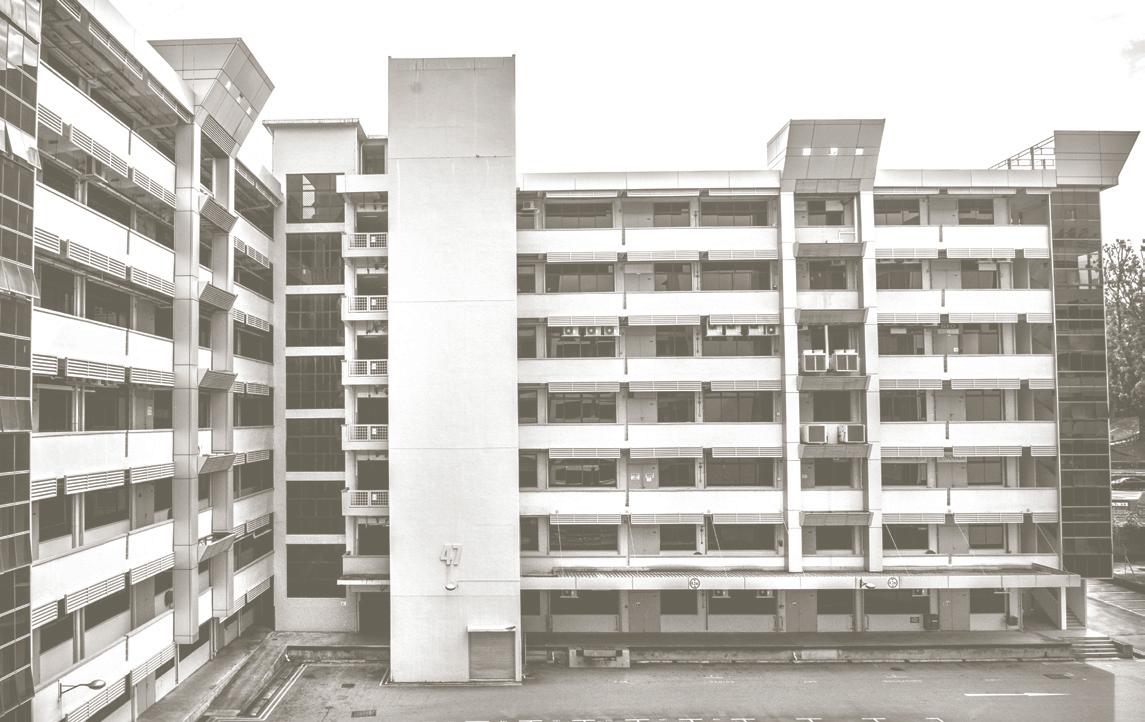 Figure 8: (a) Elevation of Block 67 facing West
(b) Large Carpark surrounded by Block 47 and 51
Figure 9: Southeast Elevation of Block 47 facing a carpark
Ayer Rajah Industrial Estate is an agglomeration of flatted factories. Conceived as part of the masterplan by Zaha Hadid Architects in 2001, the urban plan intends to form a research and development cluster with neighbouring educational facilities and accessible amenities when completed. The plot ratio is targeted to more than double from the existing 1.8 found on site to a proposed 4.0. The increase aims to create varied real estate opportunities while retaining existing structures to promote a diverse ecosystem between young start ups and established companies.
The industrial estate is flanked by two MRT stations at two ends. Plot 1 is connected to the underground walkway that leads to Kent Ridge Station, while Plot 5 is located directly opposite Fusionopolis which is connected to one-north Station. The site is situated between two key locales of innovation—National University of Singapore and one north business park developed by JTC Corporation for the Research and Development cluster compromising Biomedical Sciences, Infocomm Technology (ICT), Media, Physical Sciences and Engineering. By virtue of its proximity, the Ayer Rajah Industrial Estate draws synergistic benefits from its context.
Proposed Vision Plan
Recently, many large-scale buildings in Singapore have utilized the construction of sky bridges for inter-block connectivity and scenic views. Instead of a single routed connecting sky bridge, the research proposes a variegated ground floor, which suits the collaborative nature of start-up firms and promotes a lively community. The collective ground floor provisions open spaces with different characteristics: a lush garden, intimate triangular courtyards, a canopy-sheltered exterior space and a wide atrium. The courtyards direct light and breeze into deep floor plans found in the existing urban form. On an urban scale, the courtyards serve as breaks between built up areas and are identity markers that visually cohere the various building plots into a singular urban plan.
In order to investigate the effects of intensification and the new massing for the site, large scale physical models were made to study a variation of plot ratios and building heights (Figure 10).
Flanked by Kent Ridge Station and one-north Station, two corner blocks act as gateways to the rest of the estate. Respecting existing building heights around the site, the urban massing is tallest on both ends and decreases towards the middle. A consistent frontage is kept to create coherence along Ayer Rajah Crescent (Figure 12).
The coherence of the urban plan is established by these simple pedestrian design approaches: courtyard continuity, consistent street frontage, and coherent urban massing. By doing so, the industrial area is transformed from a purely functional space to a neighbourhood.

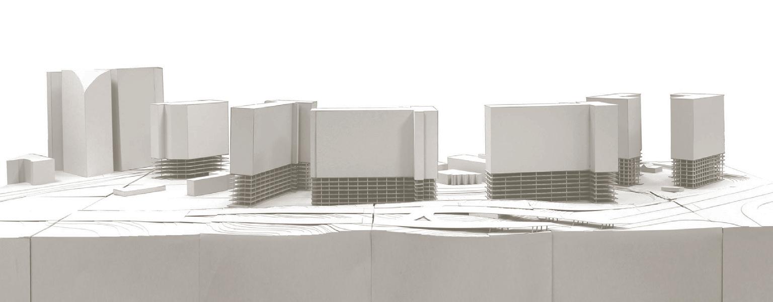

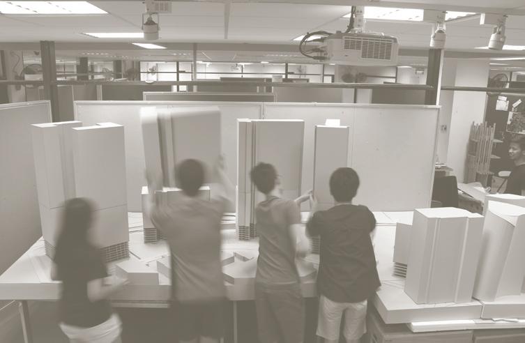
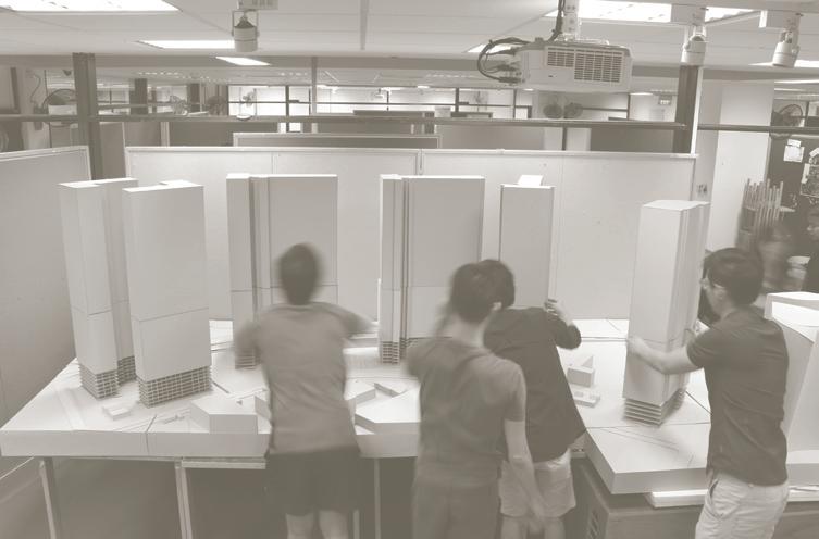

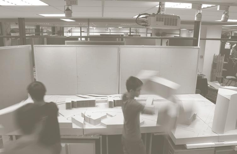

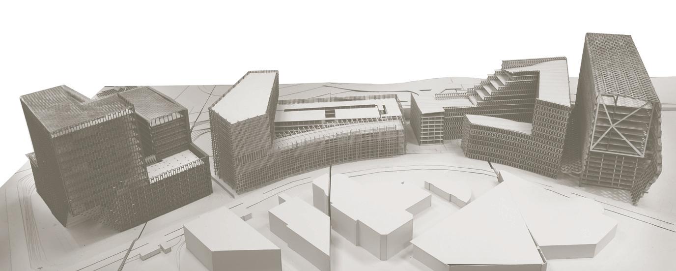


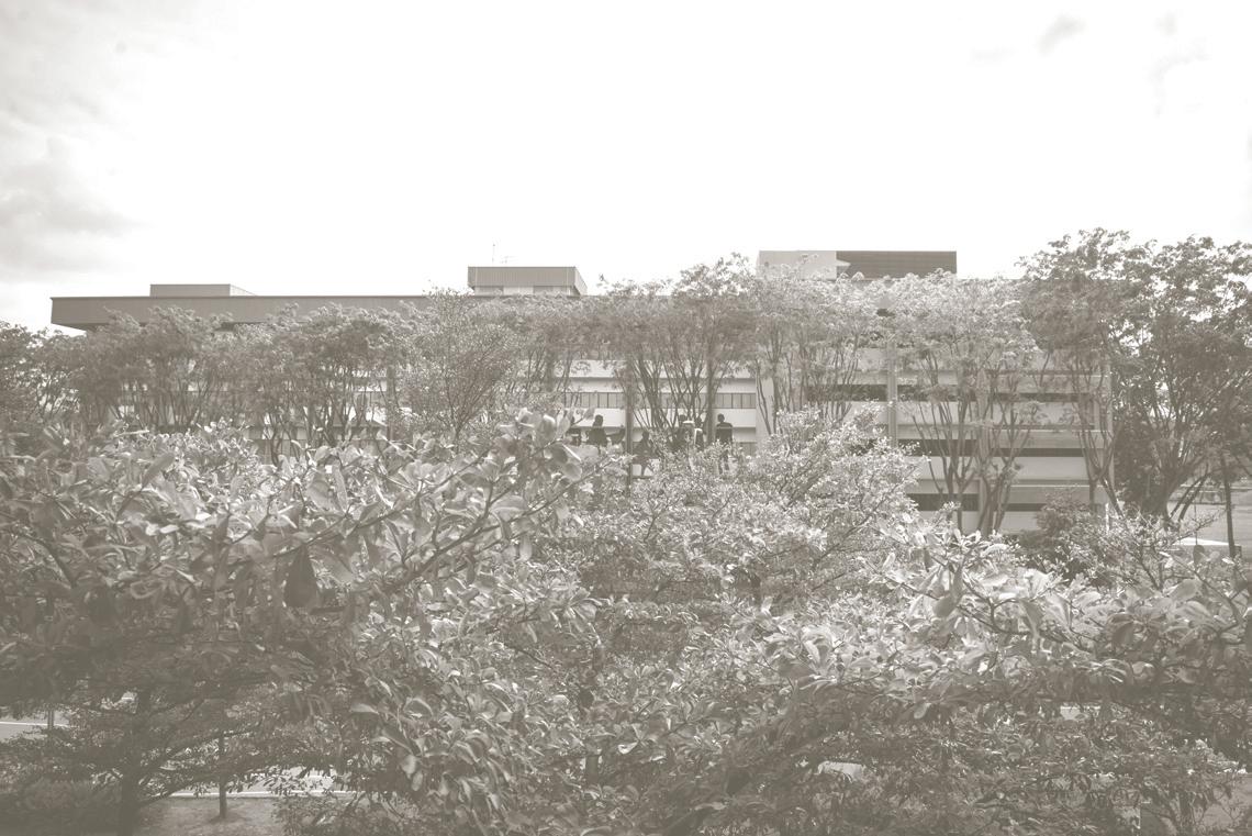
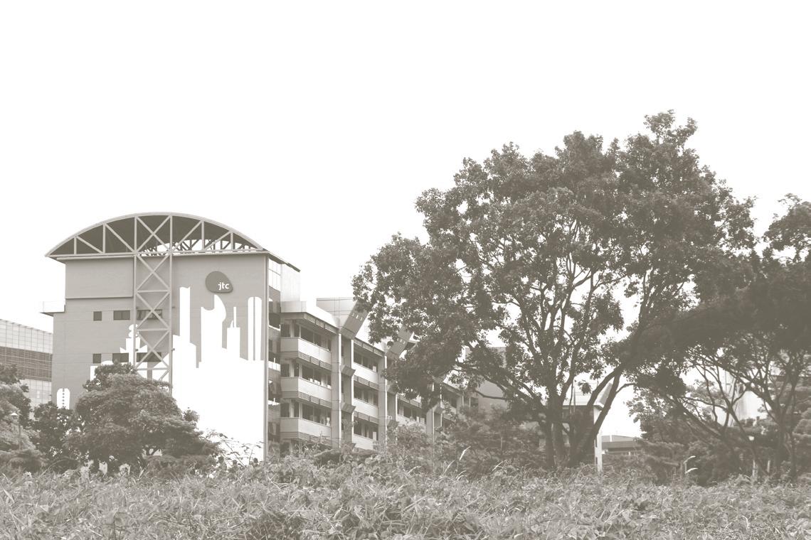
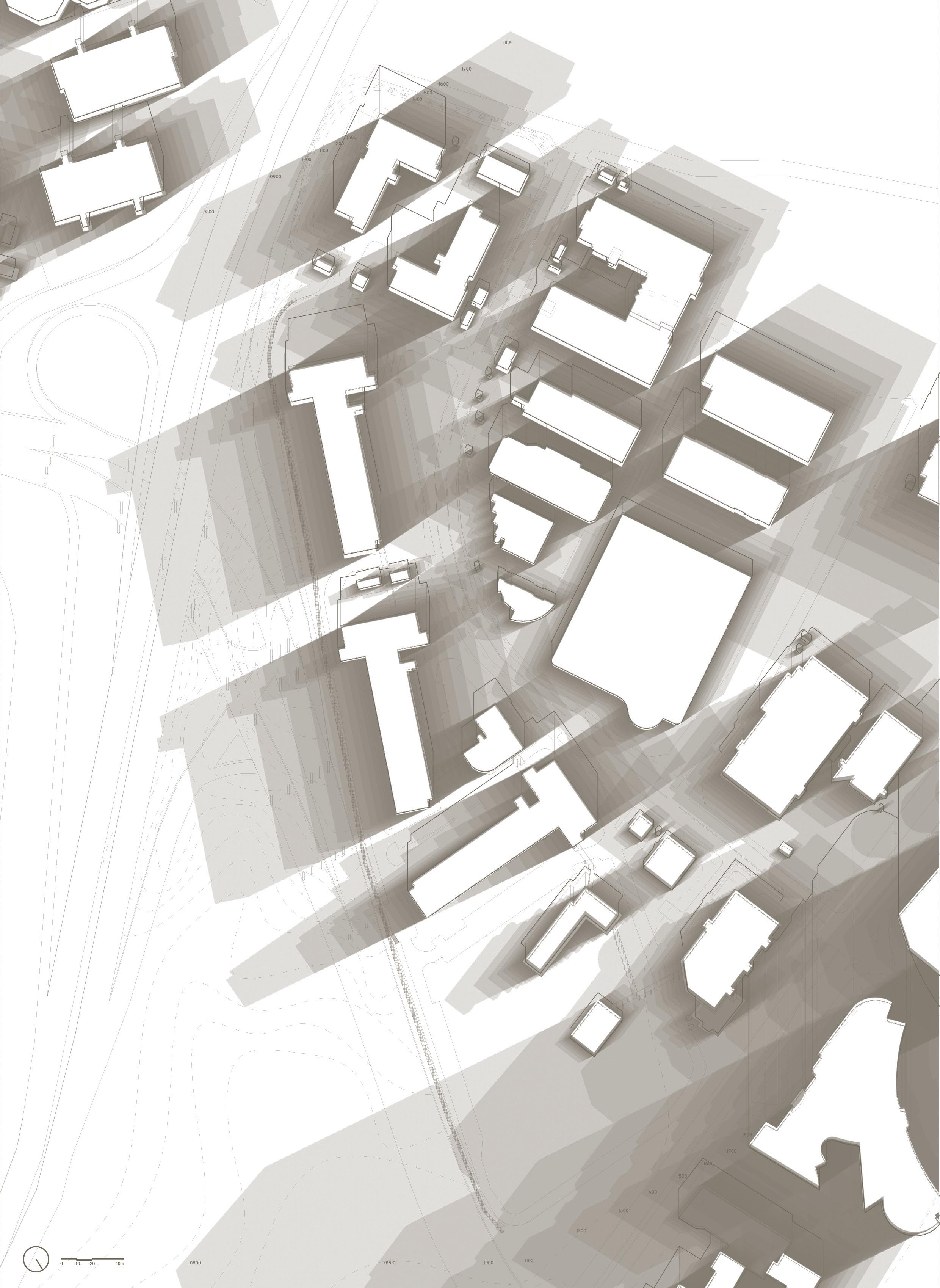
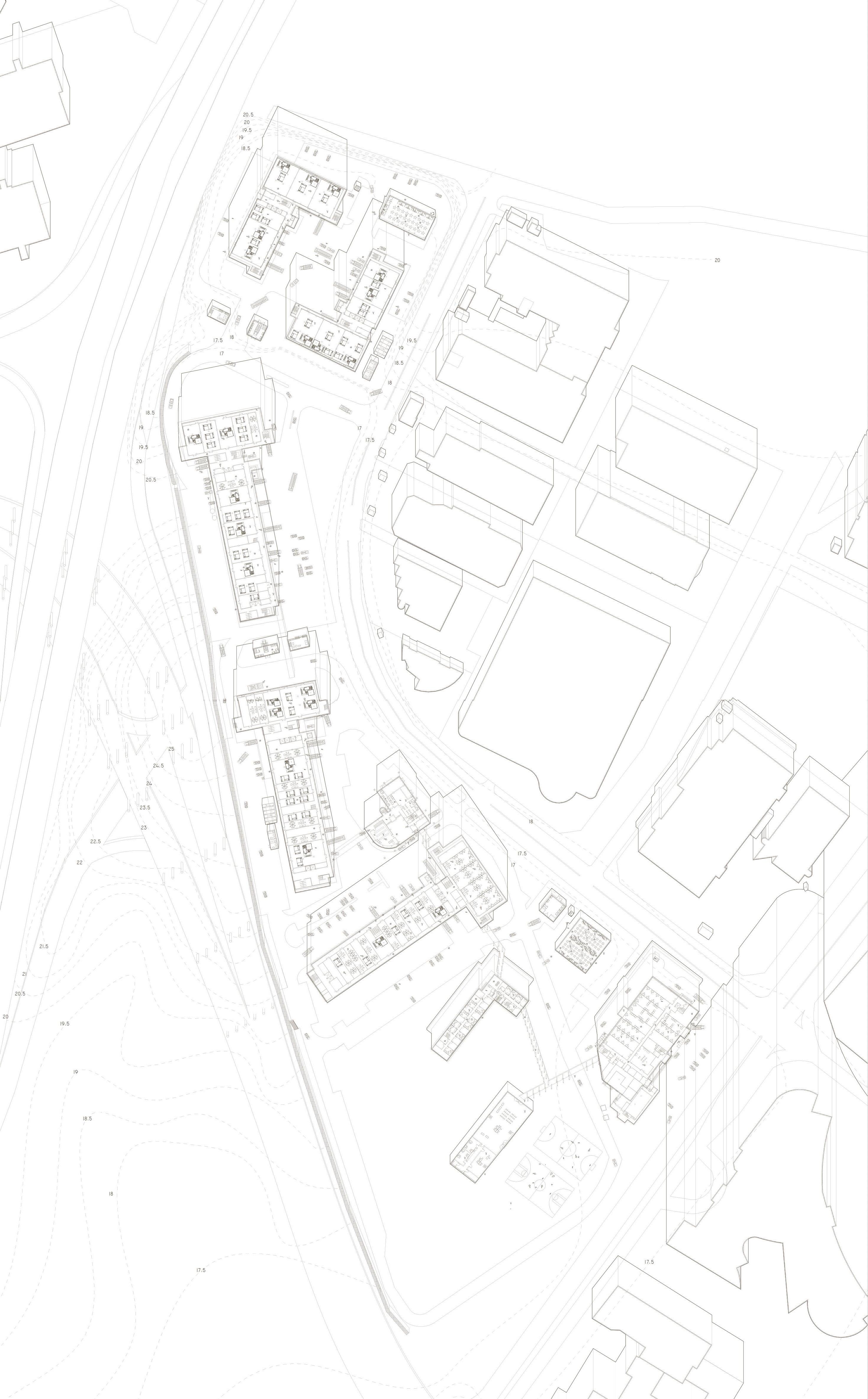 Figure 16: Site activities documented in drawing, showing everyday life on site, which includes light industry activities (such as carpentry workshops, hardware shop, and vehicular repair shop), small to medium offices, dining, vehicular movement and car parking, and people smoking and resting at the corridor.
noise and sound pollution, recorded with a hand-held sound level meter in the unit of decibel (dB), presented in the format of topography. The noisiest area on site is located to the North of Block 55, recorded at 74.6 dB, due to the presence of a metal workshop. Blocks facing the Ayer Rajah Flyover, such as Blk 55, Blk 67 and Blk 71, receive the greatest and perpetual amount of noise pollution on its West facing elevation, with an average of 62.8 to 67.1 dB. Ayer Rajah Crescent received 61.5 to 67.3 dB, however only on an occasional basis, due to less frequent traffic. The buildings on site are also less impacted by noise due to buffer distance.
 Figure 17: Worm’s eye axonometric drawing documenting the
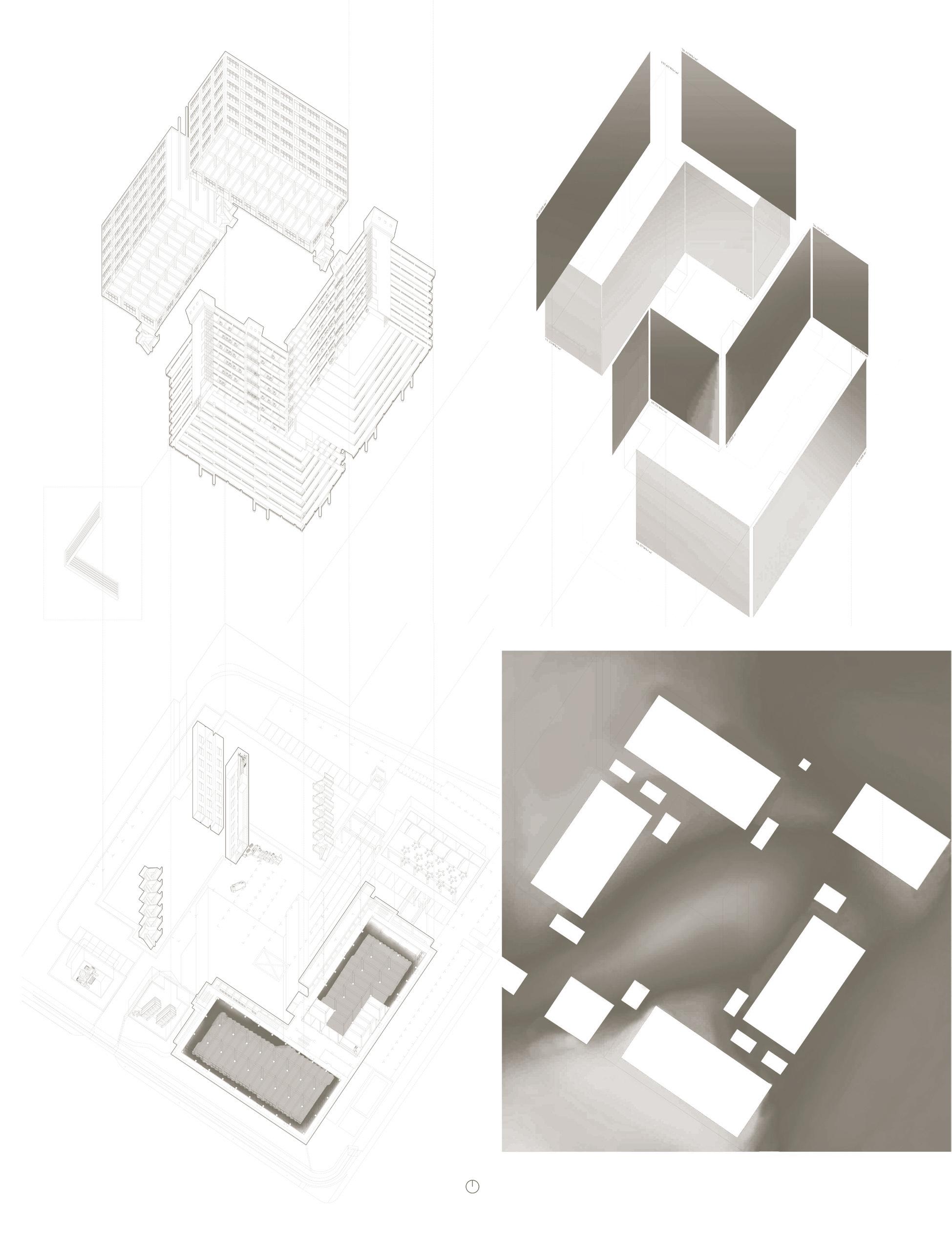
 Figure 19: Worms Eye of Block 67

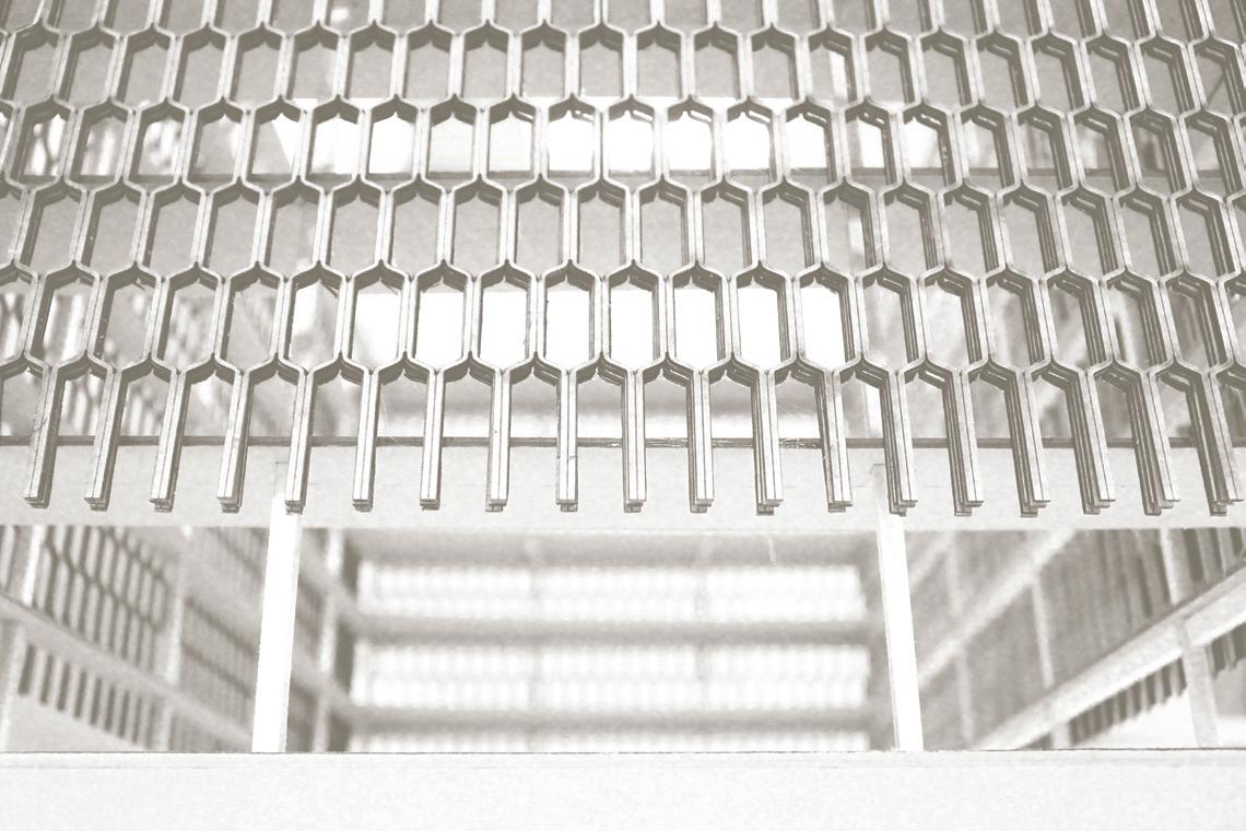
The thick block is typified by mass, solidity and, often opaque. Built with solid or heavy materials, these buildings share the physical attributes of a monolithic, standalone object-like building with a largely continuous envelope that wraps around the elevations as a veil or membrane. At times, the veil on the block’s exterior can operate structurally, environmentally or both. The thick block and its large interior floor plate is seemingly at odds with the environmental requirements of cross ventilation achieved through a narrow floor plate, often using internal air conditioning and mechanical ventilation to achieve internal comfort. Finer-grained elements on the envelope enhance the sense of overall massiveness, due to the optical contrast of small parts in comparison to the vast surface area of
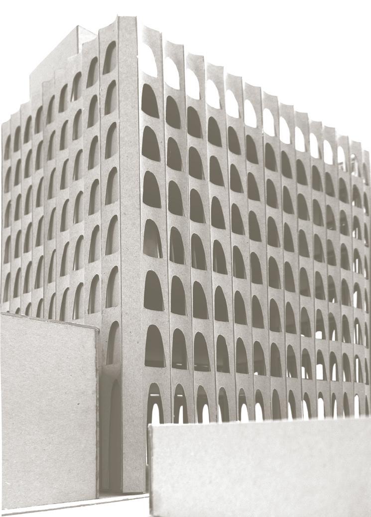
elevation. The cuboidal quality of the architecture asserts the elevation as the site of visual interest (as opposed to large scale roof forms) while simultaneously suggesting a reductive abstracted formal language traced through modernism’s use of the simplified geometry. The ornamental quality produced by the smaller components of the elevation asserts a human scale to the larger volumetric quality of the buildings. The view out to the exterior is achieved through a screened elevation, interrupted but not entirely obscured. The Thick Block is a response to larger scale floor plate requirements driven by density and corporate requirements, while at the same time allowing for improved performance and quality of comfort on the interior.
Precedent Studies: IBM Building, Hawaii, USA (1962)
 by Vladimir Ossipof
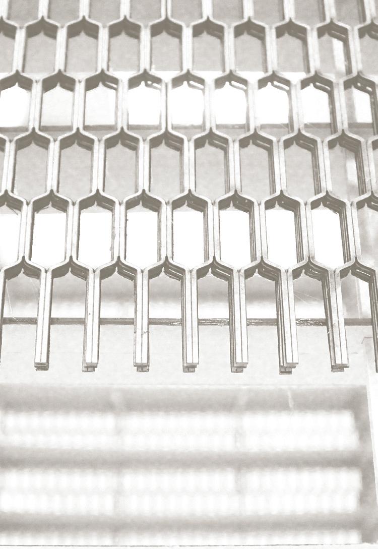
Vladimir Ossipoff’s IBM Honolulu building wraps a glass block with regular vertical sun shading device. This pattern across the façade disassociates the floor by floor registration with a continuous surface. The patterned brise soleil mediates the climatic conditions of Hawaii through the use of pre-cast concrete grilles over the glass façade and large scale floor plates required by mid-century corporate business requirements of an open floor plan. According to Ossipoff, the pattern language is based on Polynesian decorative patterns and IBM computer punch cards, transforming the then ubiquitous corporate architecture of Mies van Der Rohe’s curtain wall to one that is more adapted to context and climate. The IBM Honolulu building is strategically orientated approximately North-South along its axis to reduce direct solar heat gain found in sub-tropical Hawaii (annual mean temperature of 21°C). The envelope performs thermally to mitigate solar load. This is coupled alongside an internal Air Conditioning system largely due to the depth of the floor plate. The brise soleil is a 400mm thick concrete grille made of with a high composition of tricalcium aluminate suspended from the slab edge profile. The envelope is made up of a relatively geometrically complex screen consisting of 1360 precast concrete pieces separated from the glass window wall by a buffer of 1 metre. Ossipoff factored in maintenance for the façade by managing water runoff and potential streaking by incorporating 45° angles at regular intervals throughout the horizontal elements of the elevation.
The pattern is consistently applied to all of the building’s elevations regardless of orientation. Its singularity of approach wrestles with the combination of a modern, international aesthetic that erases difference with a local, climatically calibrated design that foregrounds context and specificity. As a thick uniform block, the architecture is a series of contradictions; a large thick volume requiring air conditioning yet screened with a solar shade, a context-sensitive exterior encompassing an international style generic glass box, and an architectural symbolism both promoting IBM’s corporate culture yet relating to the site of Hawaii.
Precedent Studies: Perpetual Savings and Loan, California, USA (1961)
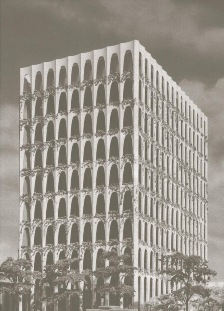
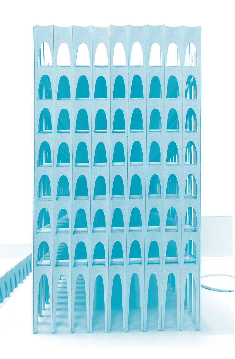
by Edward Durrell StoneThe envelope of the Perpetual Savings and Loan by Edward Durrell Stone operates as a thermal shell encasing a glass interior. An undulating scalloped surface featuring arched openings echoes the New Formalism of the 1960s. The neo-classical monumentality of the building’s articulated skin is accompanied by a front plaza and carpark in a similar axial and frontal language.
The building envelope is structural, bearing floor loads in order to reduce the number of structural columns within the interior of the building. This strategy is augmented by the primary structural core on the west-end of the building, effectively shifting the structural mass outwards in order to free up the interior space while simultaneously shading the interior from the warmer western afternoon sun. The building’s mechanical ventilation systems are situated at this west-end core, with the two elevators and service stairwell.
Plastic-formed concrete allowed for the sculptural articulation of the scalloped surface upon catenary arches, while serving as a structural envelope. Each floor is directly connected to this envelope as a suspended concrete floor slab, in tandem with only 6 circular profile structural columns within. This creates three 24-feet bays along the transverse section, spanning a total of 64 feet.
Situated in Beverly Hills, California, the building’s climatic context is Mediterranean; hot and warm most of the year. The recorded climatic average peaks at a high of 29.4 degree Celsius in August (Summer) and dips to 19.5 degrees in January (Winter).
The interior is separated by a
perimeter of window-walls set 2 feet (600mm) from the scalloped envelope, creating a climatic buffer zone that suggests a degree of passive cooling. Planters positioned at every arched opening provide further shading by draping plants and creepers. The continuation of the scalloped envelope to the west-end of the building, encasing the core, highlights the intent of a thermal shell not only for performance but also as an ornamental pattern. An unexecuted 9th floor roof garden, shown in the original drawings but never built, suggests that the architect had intended for a vegetated shell embedded into the building’s structure.
Annual average rainfall stands at 460mm, with most precipitation occurring during winter and very occasionally during summer. The steam-lined surface directs the flow of rainwater along the wall to the ground.
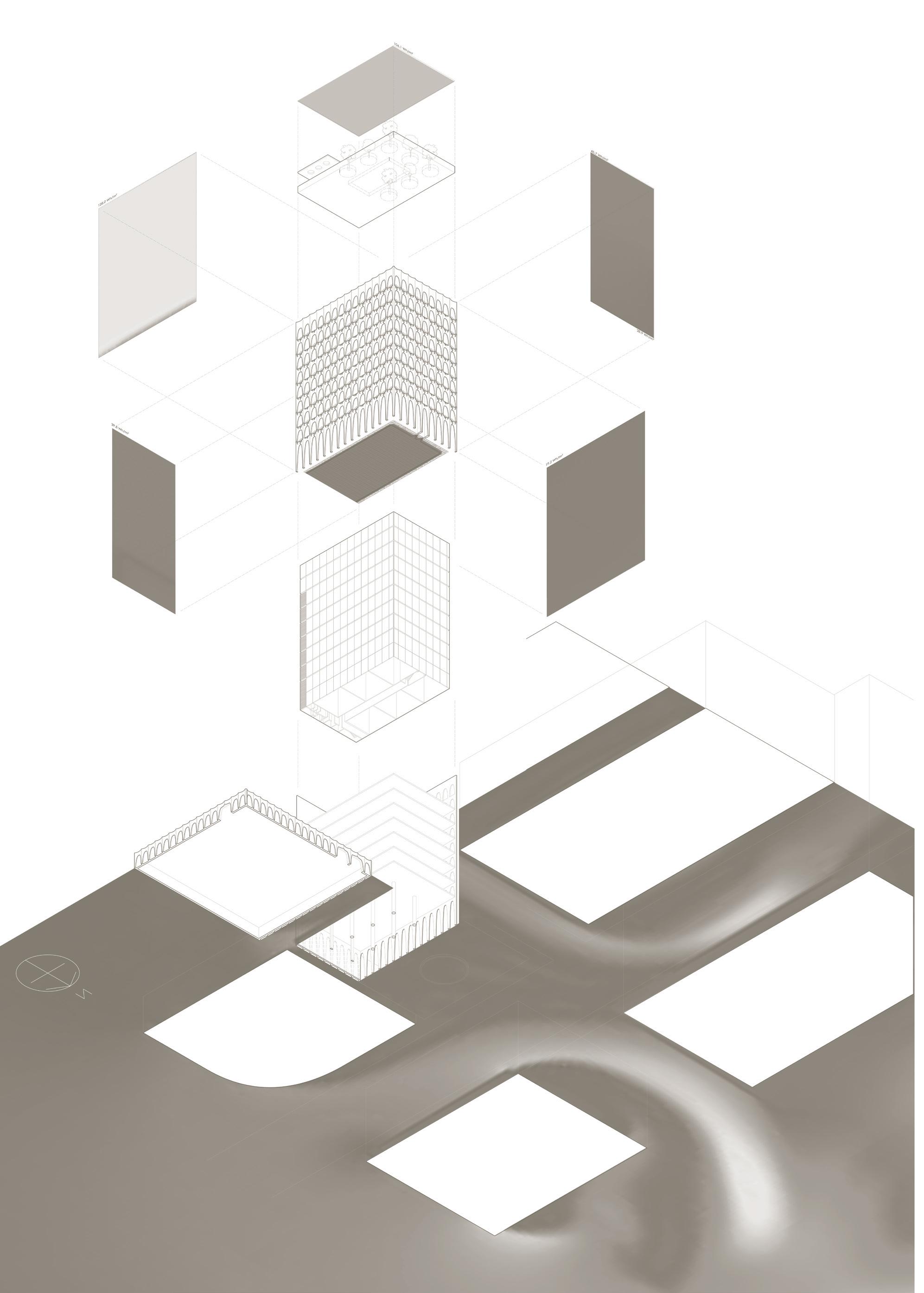
Courtyard in a Shell Block 47 & 51
by Yeow Bok GuanGlue-laminated timber (GLT) columns and Cross-laminated timber (CLT) panels are employed as relatively lightweight materials that span above the existing reinforced-concrete structure. Referencing two precedent case studies, the structure-climate dialogue is manifested as exteriorized structural mass. The two cantilevering corners of the building are supported by GLT arched beams, which are recessed into the building.
Vertical GLT columns hug the perimeter. With the North-South facing orientation of the building, simple perpendicular extensions generate sufficient shade. This veil of vertical fins responds in varying opacity towards the East-West path of the sun. A strict verticality is adhered to, allowing for as much daylight as possible to stream into the thick 20 to 30 metre deep sections.
A two-metre offset from the existing perimeter for the structural foundation of the GLT columns
serves as a threshold. A playful variation in distance between the columns shields the building at some points while allowing minimal rainfall into the peripheral corridor spaces, where circulation is minimal. The vertical columns become closer and denser towards the North-east and Southwest corners of the building, buffering against the heavy wind-driven rains that Singapore experiences during the North-east and South-west monsoon seasons.
The layout of CLT wall-panels ensures that spaces are cross ventilated. An arched profile also allows for wind in the axially-perpendicular direction. Partitioned spaces are individually air-conditioned, yet coupled with the option of being thoroughly cross-ventilated. This gives tenants both the flexibility and responsibility over their reliance on mechanical ventilation and cooling, while operating as a hybrid-ventilated space. At the urban-scale, the building’s Northeast and South-west lifted corners also serve to allow prevailing winds to sweep through the central courtyard.
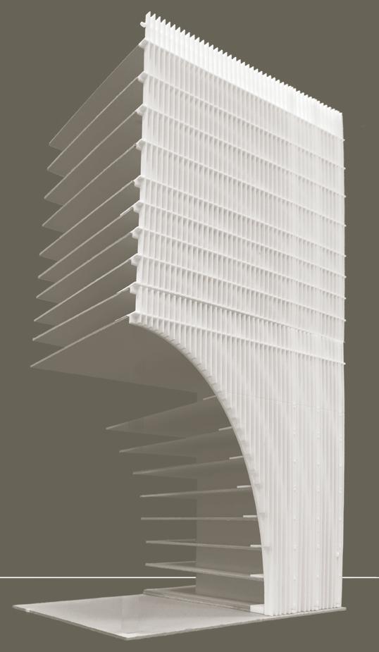

Conoid Building Block 47 & 51
by Josef OdvárkaThe design solution of a conoid façade offers permanent shading of at least 75% in the most sun-exposed eastern and western façade surfaces. Two corridors are designed in both the outer and inner (atrium) perimeter of the façade in order to shift the inhabited spaces deeper into the floor plan and further decrease the amount of direct sunlight.
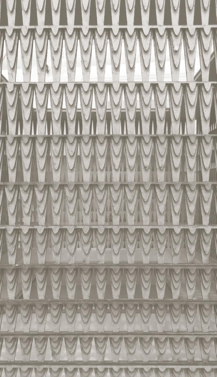
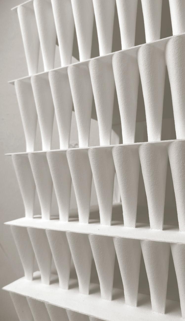
The floor plan is designed with cross ventilation and floor to floor height of up to 10 metres, allowing hot air to rise above the inhabited area and naturally circulate. Hot air then escapes from the building through holes in the shaded atrium. East-west prevailing wind is funnelled through the entrance space
between the L-shaped buildings, creating constant air flow within the atrium.
The thickness of the outer façade including the corridor is up to 4 metres, preventing rain from entering the inhabited areas. Together with strategically positioned glass partitions, the favourable conoid shape provides sufficient protection against rain. Rainwater from the conoid façade is collected in a large drain pipe within the transfer floor. Autonomic dripping from each floor and through carved floor slabs causes the building envelope to perform as a visible drainage device. In so doing, the functionality of dealing with rain water is rendered as an experiential and poetic device, reasserting the tropical atmosphere and its integration with architecture.
Triple Elevations Block 47 & 51
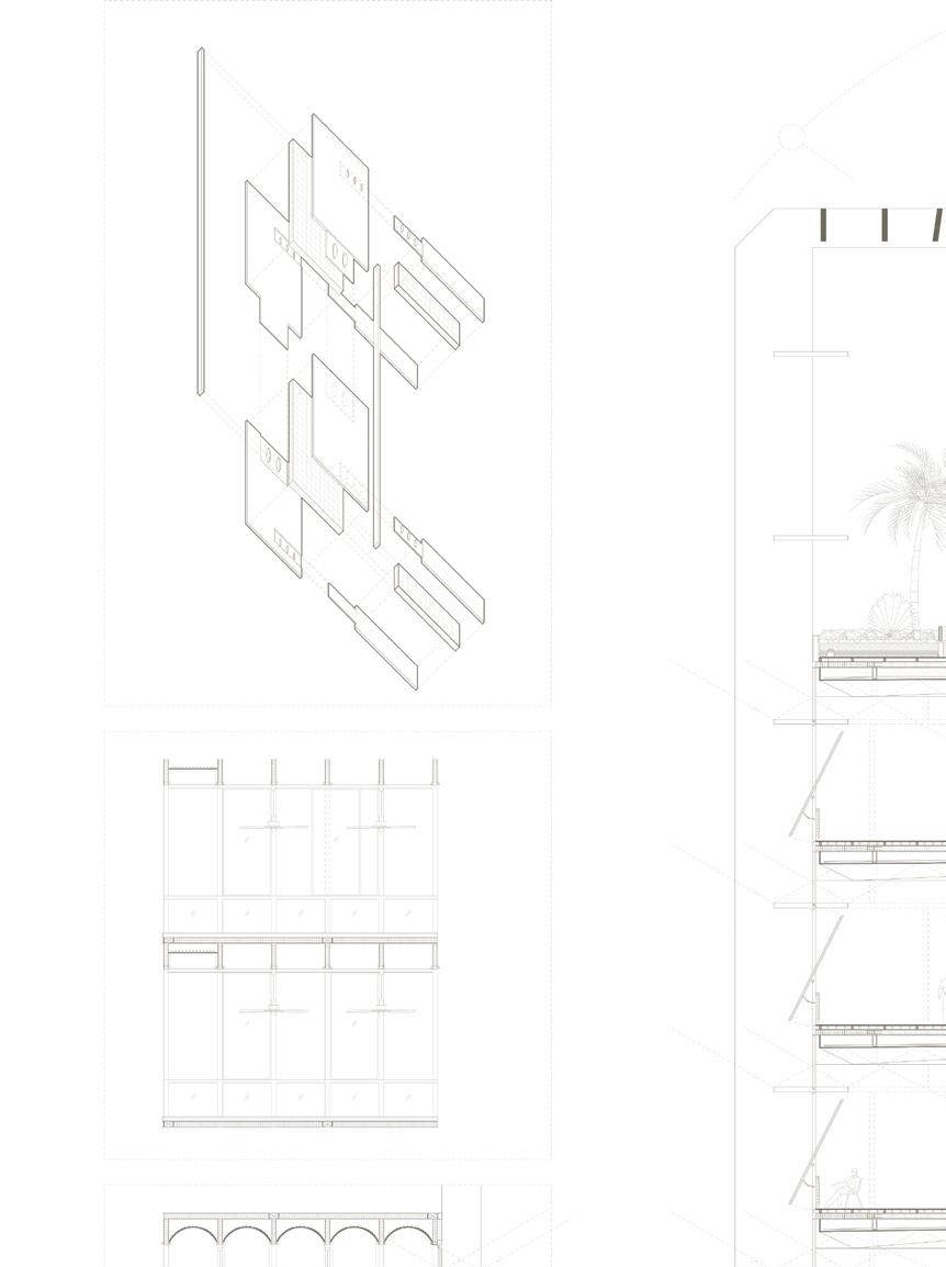
by Azizul Izwan, Joel TayThe elevation is composed of three main envelopes: the ‘outer’, the ‘inner’ (Figure 30) and the ‘non-structural’ (Figure 31). The ‘outer’ is made up of alternating rows of light shelves and tables to allow in more diffused light and keep out direct sunlight. The ‘inner’ is composed of triangular folds that act as sunshades, keeping the rain out and directing the view downwards. The ‘non-structural’ envelopes sport a discontinuous vertical element segmented by rows of light shelves. The depth of each envelope is calibrated by their positions on the inside-outside and east-west direction. Different as they may seem, the three elevations read as a unified whole characterized by their vertical elements, proportions and materiality.
The new masses sitting lightly atop the existing Block 47 and 51 buildings are supported by the Structurally-Insulated-Panel (SIP) elevation that drapes over and hugs tightly around the existing building. The upper floors are supported by “waffle slabs” supported on both ends, like a series of tables stacked perfectly on each other. On the underbelly of the “waffle slabs” are a series of catenary vaults that taper out to a flat surface from the outer to the inner elevation. They serve both to provide lateral support and to diffuse light gently into the inner spaces. The incline of the vaults become progressively steep from the highest to the lowest floor, in response to the varying angle of incidence of sunlight.
The SIP facade and waffle slab enables the creation of column free upper floor spaces (Figure 33). These floor plates are dissected into three thermal zones: namely, the Air Con-
ditioned (AC) zone, Transition zone, and Hybrid zone (made up of chilled ceiling panels and floor slabs, dehumidifiers and mechanical fans). The AC zones are located on the eastern corners of each block to reduce energy wastage from increased thermal load of the western sun, while a 6-storey pyramidal void is employed at the western-most and ‘hottest’ corner of the building, behind the ‘outer’ façade, to decrease thermal load and allow for the stack effect. The AC zones are separated from the Hybrid zones by the Transition zones to help deal with condensation. The remaining floor area is thermally controlled by natural ventilation with the aid of the chilled ceiling panels and floor slabs to absorb heat from machinery and human processes, and mechanical fans to aid ventilation.
The main massing strategy of the project is to emphasize and enhance the spatial quality of the implied courtyard by completing the loop of the two existing L-shaped buildings. The overall building height is also increased to meet the required GFA whilst increasing the degree of enclosure of the courtyard to create a more intimate space that houses a hidden oasis of jungle amidst the industrial complex. Thus, the addition of two more L-blocks above the existing structures results in the creation of two massive urban gateways on opposite corners of the site, oriented in an east-west direction. This gesture welcomes visitors into the jungle within as they enter the complex on either side (Figure 32).




Courtyard Office Block 75
by Cho Jeong Hyun, Phang Hui LingAs the block facing Fusionopolis and one-north Station, Courtyard Office acts as a gateway to the expanse of the Ayer Rajah Industrial Estate. The building parti is conceived as a porous massing that draws in from the surroundings external elements such as sunlight and breeze.
In response to the deep triangular plan, an inner courtyard is introduced to create a shallower block that promotes natural ventilation. Hence, large holes are punctured through the elevation of each side with at least one overlapping level to facilitate cross ventilation through the building. The central courtyard is connected with the various vertical courtyards in terms of form and expression (Figure 36). The joined courtyards gain a dramatic three-dimensional quality by opening to the outside vertically to the sky as well as horizontally to capture the breeze. The internal envelope that clads these openings expresses itself as a singular, continuous volumetric entity.
The general structure of the building performs like a tripod, standing on three legs above the existing building. The central volume slants downwards to avoid the existing building. (Figure 35) This slant creates diminishing floor plan depth with every increase of level, which lessens the load for the structure. The cascading levels allow daylight to reach the deeper floors at the lower levels.
There are two systems of envelope in place, i.e. the external and internal envelopes, diverging at roof level (Figure 37). Both envelopes increase their opacity as they approach the top, due to higher sun exposure. The opacity varies vertically and not by its facing orientation. This is
because the Western sun is shaded by the close proximity of a future high-rise project to the West of the building.
The external envelope is made of PTFE fabric with lightweight aluminium frames in the form of outward slanting diamond shapes. The envelope performs the task of shading the sun and repelling rain. Its appearance is designed to correspond with the diagrid. Concrete slabs on each floor support the aluminium frames. By adjusting the angle of slant of the frames, the opacity of the building is engineered to increase along its height. (Refer to elevation in Figure 38)
The inner envelope is a polyvalent element made of wooden louvres that connect the various openings at the central courtyard to the rooftop. On the office levels, the louvres extend inwards at an interval of every four members to perform as light shelves to the interior office space. At the roof level, the horizontal members grow closer to each other with decreasing gap in between. At the point where the members are perpendicular to the sky, vertical panels are added to the envelope to provide greater sun shading.


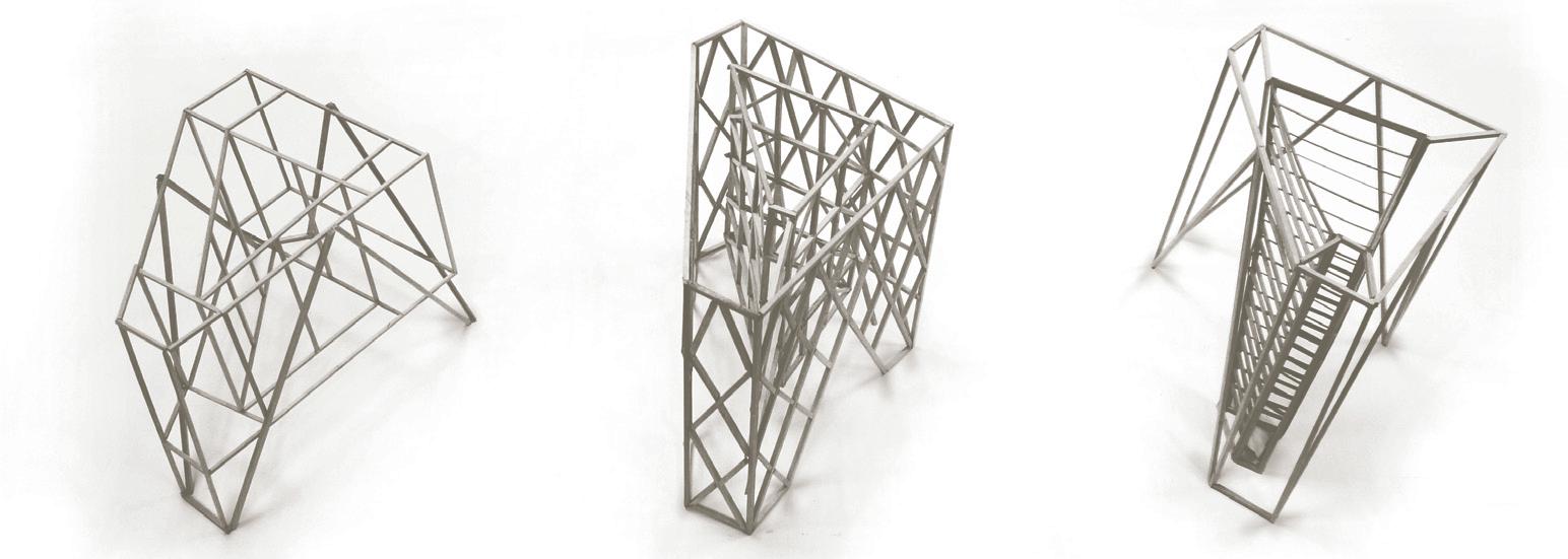


Structural elevations are predicated on locating columns along the building perimeter as a component of the elevation. By doing so, the internal floor plate is left open for flexible interior partitioning. The added benefits allows for utilizing the structural member as a sun shading device to improve the envelope’s performance. Often, the structural member is rendered in a finer profile that double functions as an ornamental pattern, as found in the Wing On Life building or The American Cement building. As

in “Thick Blocks”, the surface articulation of the elevation produces a dramatic optical quality while being embedded with structural logic. In short, structural elevations expediently resolve the primary functions of architecture; to carry gravitational loads, to provide for climatic separation, to accommodate performance and functional requirements between the interior and exterior, and to articulate a delightful play of function and ornament.

Precedent Studies: Wing On Life Building 150 Cecil Street, Singapore (1975)
by James Ferrie and PartnersLocated along Cecil Street and Stanley Street, the Wing On Life Building, also known as AXA Life Building, was constructed by James Ferrie and Partners Architects. The firm was known for additional works such as the Van Kleef Aquarium and Odeon Cinema, which shaped Singapore’s landscape in the 1970s. The building, on a site of approximately 30 metres by 40 metres, was completed in 1975 at the cost of $25 million to serve as an office tower in the developing financial center. The 64 metre tall building comprises of a podium block made up of the mezzanine floor and two upper floors, and the tower block from the fourth level onwards. The structural core contains 2 escape staircases, 3 passenger lifts, 1 cargo lift and 2 AHU rooms per floor.
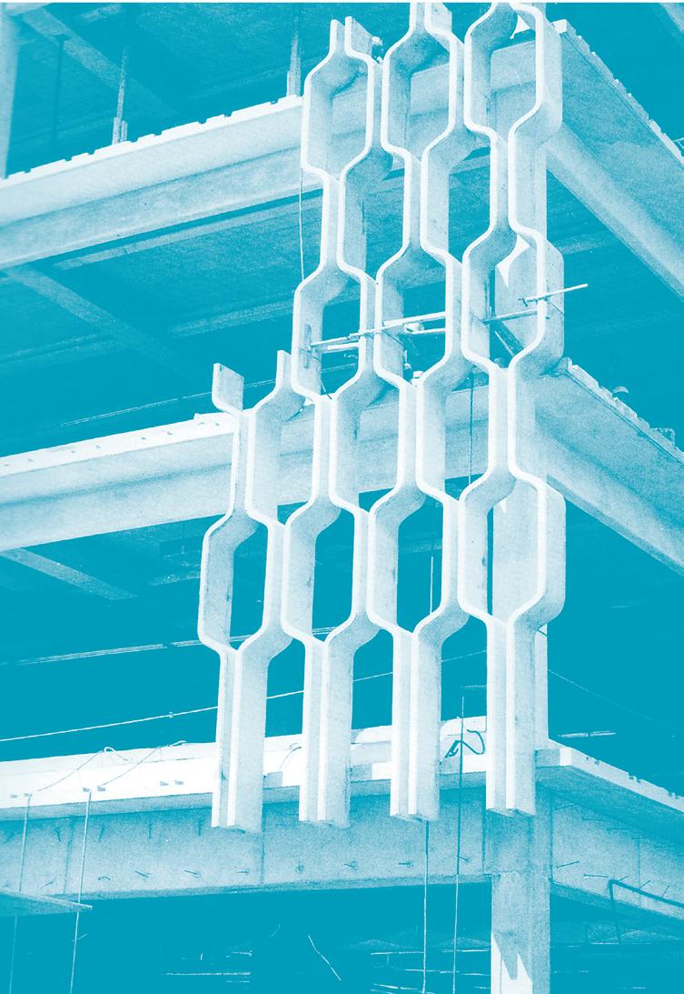
The 20-storey building (including two basement levels for carpark) comprises of the podium block, which is supported by 6 structural columns, and a 12-storey tower of uniform office spaces and penthouse. The distinguishing architectural feature is a series of 100mm thick twisting structural concrete mullions on the periphery of the tower block that serve to transfer gravity and lateral loads. These twisted structural elements are four times stronger than straight columns for a similar cross sectional profile. Additionally, the floor slabs are constructed with pre-stressed concrete. Column-free interiors allow for an open office typified by the financial services sector.
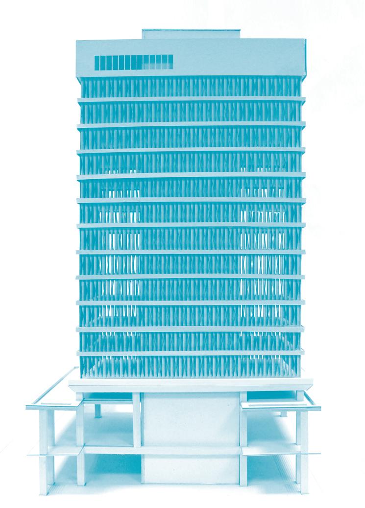
Besides functioning as structural supports, the twisted concrete structural elements operate as sun-shading devices on both the East and the West-facing facades. These structur-
al elements shade approximately 45% of the direct sun-rays from the interiors. In addition, the floor slab overhangs at 900mm depth from the windows, to further shade the interiors from the sun.
The annual rainfall count stands at 2450mm in Singapore. Rain is presumed to hit on the overhang and window panels as surface runoff. 300mm high and 150mm thick concrete curbs prevent the rain from entering into the interior. The tapered beam on the foot of the tower block directs the surface runoff into the drains on the roof of the podium tower. Water flows through the pipes of 200 mm into the rainwater discharge drains beneath the ground.
Designed as a fully air conditioned tower, the building is installed with a centralised air conditioned system which comprises of a cooling tower and chiller to direct chilled water to the AHU units on each level. Due to the low speed and position of the core, natural ventilation within the office space is limited.

Precedent Studies: American Cement Building, Los Angeles, USA (1964)
 by DMJM
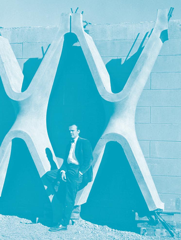
The American Cement Corporation headquarters utilizes reinforced concrete as the “the building material of the future” as a form of self-promotion, symbolic of the owners ambitions. The site is opposite MacArthur Park, just east of downtown Los Angeles. Together with DMJM, Edward Rothschild and Arthur Gilbert (building owners) specified the design of a column-free office space that was seismic compliant, column free cost competitive when compared with non-concrete structural systems and materials.
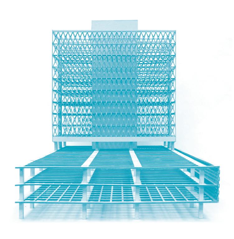
DMJM designed the 13-storey building as a two–unit structure: consisting of a 4-storey base for parking, ground floor shops, lobby, and executive offices and a 9-storey tower, with each floor containing 12,000 square feet of speculative space. The shear-resisting and load-bearing concrete service core extended through the tower and housed four elevators, stairs and utilities. The tower grill performed dual decorative and structural roles. It was composed of 225 X-shaped reinforced concrete elements that were prefabricated off site. Together with pre-cast floor beams and a central core, it formed a more conventional beam-and-column system that allowed designers to open up the office space as column free. Crews used the cast-in-place floor slabs to tie the various building elements together. The grillwork that wrapped the parking area was designed for decorative and ventilation purposes.
Because the temperature in Los Angeles stays reasonably high, the building does not have a heating system. The pre-cast concrete X-shaped
members provide general shading. For extra shading, tenants have installed internal curtains.
The American Cement Building incorporated mechanical and HVAC engineering in project planning and design. The building was cooled using natural gas-powered absorption refrigeration unit that the subcontractor installed on the roof. The absorption unit received significant
criticism as an inefficient with a low life expectancy. The current replacement system, utilizes a split system packaged for each tenant. North-east and South-west facades are fully operable for cross ventilation assuming an open office configuration.


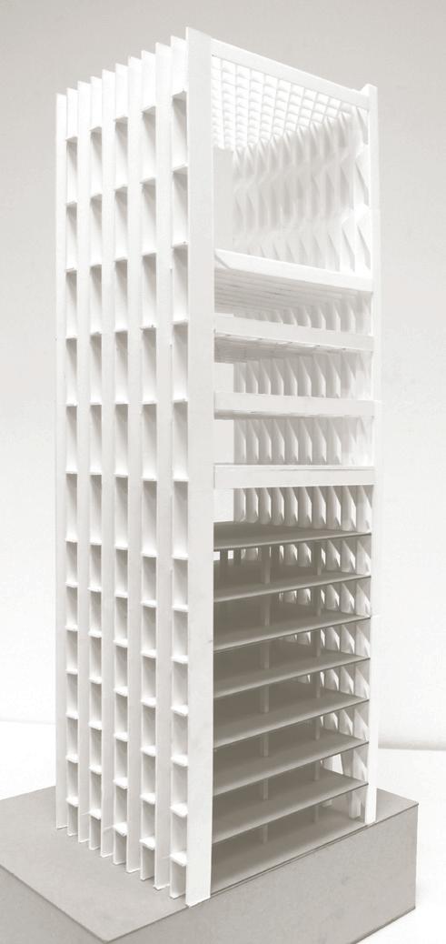
Elevate Building Block 71
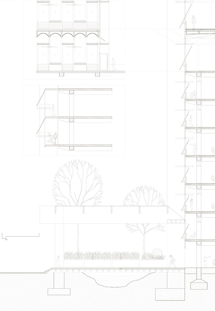
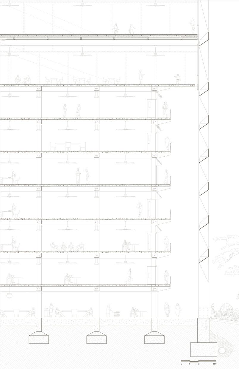
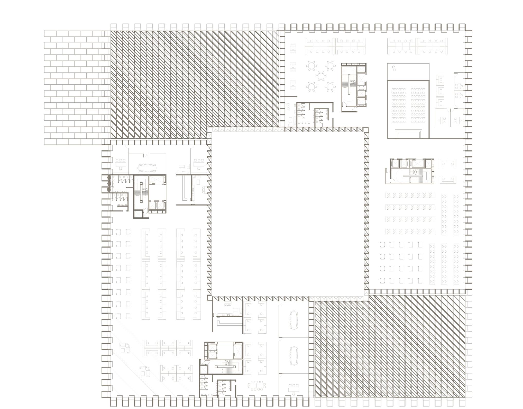
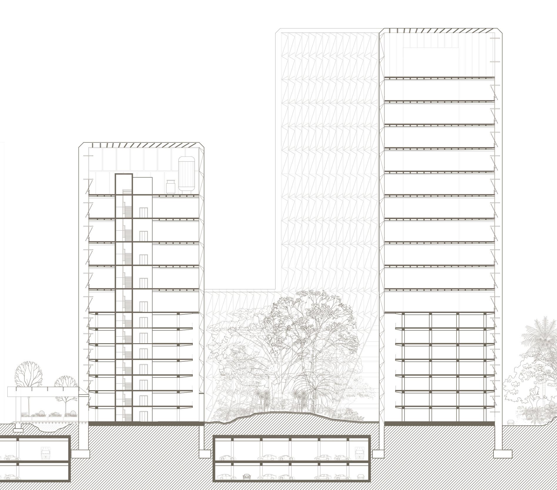
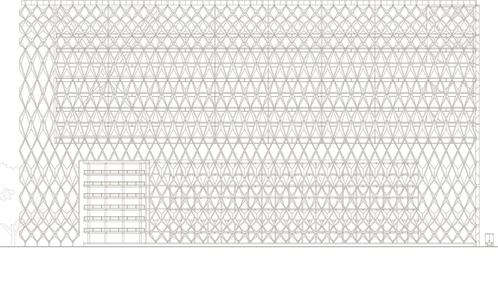
by Iven Peh, Greta VarpucianskyteDue to the narrow site, expansion in office space is only made possible through constructing above the existing structure. Adhering to the rules of the masterplan, the envelope become an opportunity to craft open spaces. On the South elevation, the modular flexible skeleton unfolds into a sheltered canopy to extend the atrium space to the neighbouring building (Block 67). Similarly, the monolithic north elevation demarcates a boundary between three buildings (Block 79 and future skyscraper) to encircle a courtyard. It also bends to reveal the existing building. The envelope follows the curvature of the site and exposes the cantilevered volume on the east façade. Seven new floors hover above the existing building. Besides the ground level atrium, private gardens are planted on the existing roof and new roof top to achieve approximately 120% green plot ratio.
The diagrid structural exterior directs the load to the envelope. The definition of an envelope is usually accompanied with preconceptions such as surface, boundary, shell, skin or façade. In order to push the interpretation of the envelope, firstly, a secondary filigree structure is devised as the envelope for the existing building and the structure for the new addition. Secondly, instead of viewing the envelope as a surface, this endoskeleton reads as a volume within a volume. In order to accentuate the secondary volume, circulation cores are carefully positioned between the outer and inner envelopes. Lastly, the envelope becomes a form of inhabitation. Each twisted pre-cast concrete with built-in joint connects to one another and to the floor beams. The heights of the modules vary to meet the minimum required headroom. The three-dimensional Y columns support the folded canopy and set up the grid for the parking lots in the basement. Similarly, the partitions of the new levels are
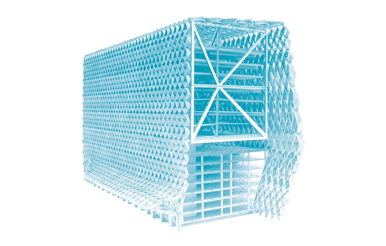
organised according to the structural span between the trusses.
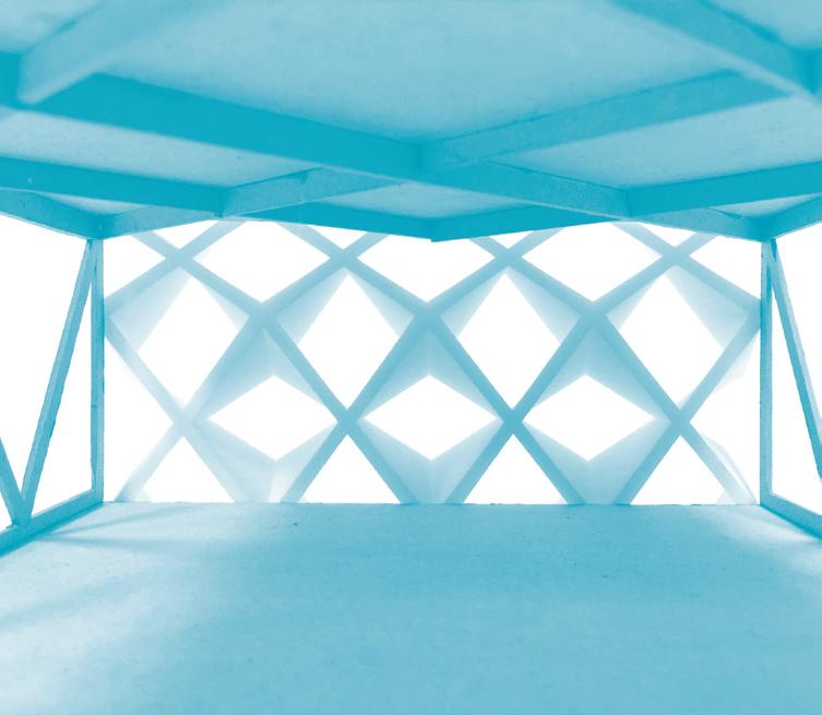


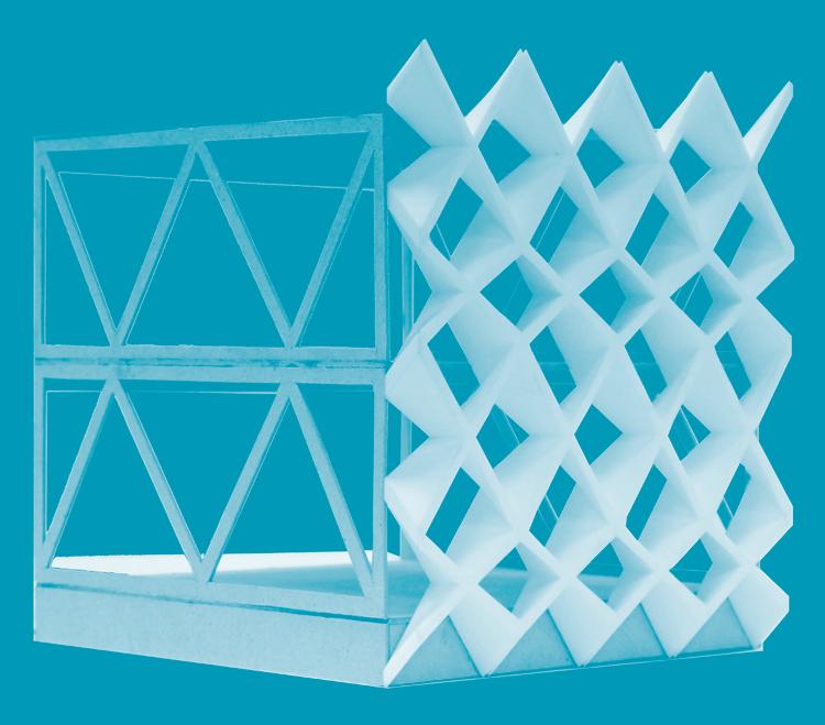
The building receives the high solar insolation on the roof, West and East façade. The twisting ornamental concrete structure façade shades the roof and West façade. The greening strategy on the rooftop further reduces the solar gain on the roof elevation. The overhanging envelope shades direct glare into office space on the East-facing façade.
Rain becomes the primary concern for the narrow building as its elevations face the North-east and the South-west monsoon rain. Instead of kerbs, the cast in gutter at approximately 800mm width channels the rainwater into underground drains. Two water tanks are located beneath the roof top garden and on the ex-
isting roof top. The collected water is then used for irrigation and grey water purposes without the need to pump water above ground.
The existing office spaces are naturally ventilated due to the low rental cost for start-ups. Temporary volumes are arranged on the existing floor plan to facilitate a balance between private and social spaces in a vibrant start up environment. The new prime office spaces employ variable air volume (VAV) system for supplying cooling and fresh air. Air conditioning spaces are reduced to minimum with naturally ventilated communal 12m wide corridors. Voids are punctuated to invite light into the canopy. Operable windows at intervals allow inhabitants to receive fresh air.

Stacked Envelopes Block 67
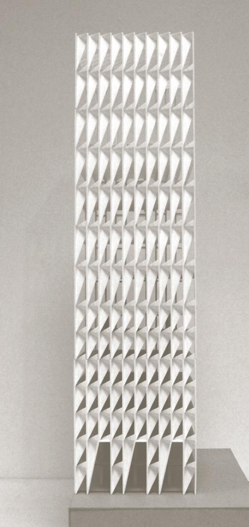
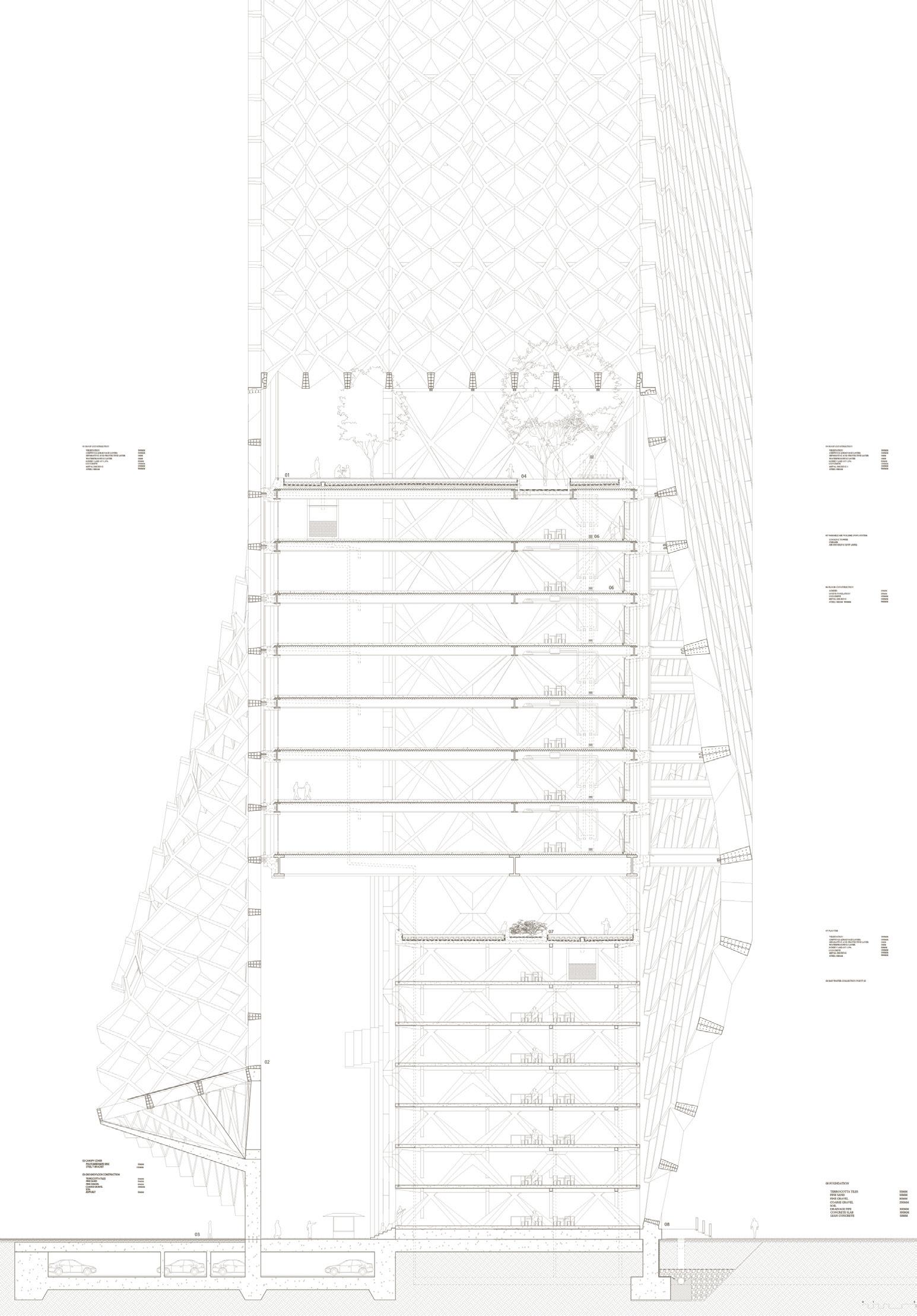
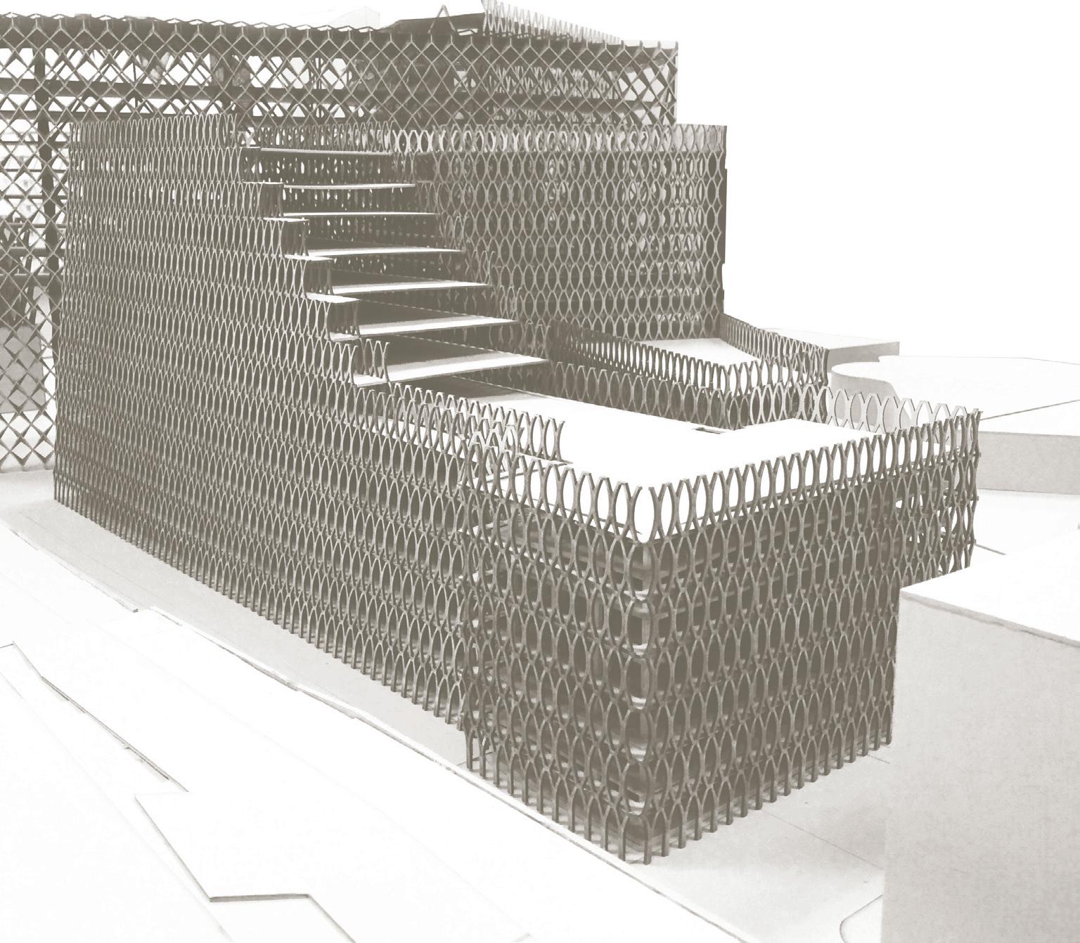
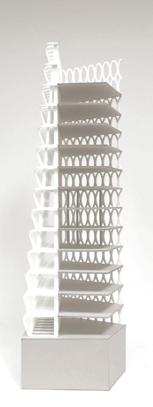
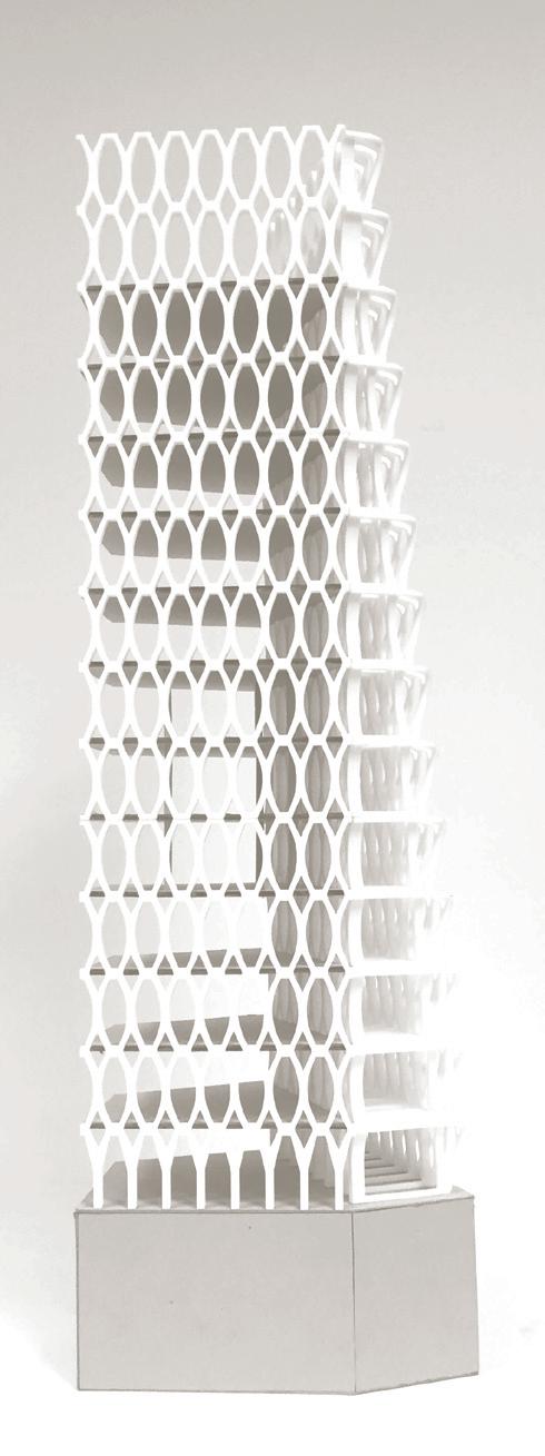
by Quentin Sim, Shawn TeoIn adhering with the urban plan, the proposed design was organised to define a trapezoidal courtyard in plan, while allowing for increased floor areas above the existing building. A new additional massing hugs the perimeter of the site to the east so as to maximise the plot coverage and provide continuous street frontage. Surrounding the blocks is a series of verandahs that host a vertical landscape of vegetation, trickling down towards the green envelope of the adjacent plot (see Weathered Factory).
The envelope has polyvalent properties dealing with Singapore’s intense western afternoon thermal load, rainfall, and traffic pollution (Figure 54) due to its proximity to the entry on-ramp to the Ayer Rajah Expressway (AYE). Concerns for natural daylighting and acoustic buffering also influenced the porosity and opacity of the envelope. In addition, the envelope serves as a structural scaffolding, allowing for additional floor plates above the existing building.
The design borrows from the modularity of the IBM Honolulu and American Cement Building. The effective depth of the aforementioned case studies varied from 600mm to 1100mm. This was scaled to a deeper dimension of up to 1.5 meters to accommodate tropical environmental conditions. The pattern’s thickness thins down when the demand to perform thermally is reduced. Conversely, a deeper profile is maintained on the West elevation where the necessities of thermal and acoustic buffering are the greatest.
The formulation of the structural module, elliptical in elevation and spanning floor to floor, is based on
research into the internal day lighting of the floor plate, thermal load reduction, acoustic dampening, and structural efficiency. Thus, a ratio of thirds was used in determining the curvature of the concrete profile, taking into consideration that the top one-third will facilitate indirect day lighting as a light shelf, the middle third provides appropriate views to the exterior and the bottom third operates as an efficient transfer of structural loads.
The overall massing is angled towards the western elevation, thickening the depth of its perimeter closest to the highest level of noise. This double thick space operates as an acoustic buffer while being structurally efficient. The terraced upper floor plates link the mass to its overall plan wrapped in a simple yet elegant pattern.



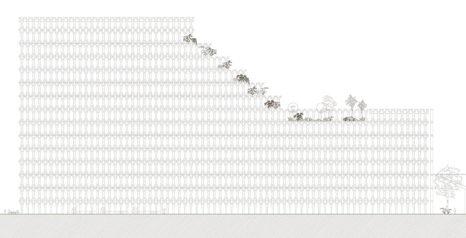
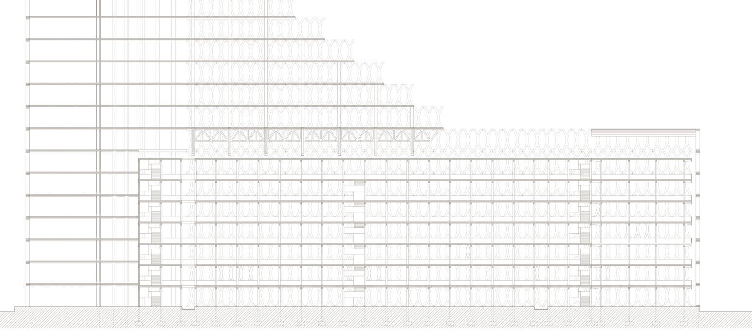

Buildings with envelopes covered in vegetation project themselves as veil-like organic membranes and have been a preoccupation of architects merging the natural and the artificial, creating increased surface area for planting.
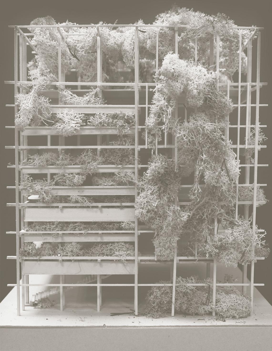
The Kandalama Hotel by Geoffrey Bawa (Figure 57) is situated in nature, sitting lightly on the ground atop columns, allowing a nearby stream to flow through underneath while being covered in a wild coating of natural green plants. The Weathered Factory (Block 55) (Figure 58) is situated in an industrial estate, flanked by other factory buildings and a major highway. The green envelope helps Kandalama Hotel to blend in with its environment, while in contrast it makes the Weathered Factory (Block
55) stand out from its surrounding paved surfaces.
In Southeast Asia, vegetation tends to be over-abundant, thick, and continuously growing. Strong sunlight coupled with high rain volume contributes to a favourable condition for unruly and fertile growth of vegetation. In the context of Singapore, this vegetation tends to be manicured and trimmed to approximate temperate looking landscapes. However, the Kandalama Hotel and the Weathered Factory suggest an alternative, embracing the wild and unkempt. Operating as both and an aesthetic veil and a performative elevation, the natural green elevation suggests an alternative architectural devices to modulate heat, humidity, rain, and sun.
Precedent Studies: Kandalama Hotel
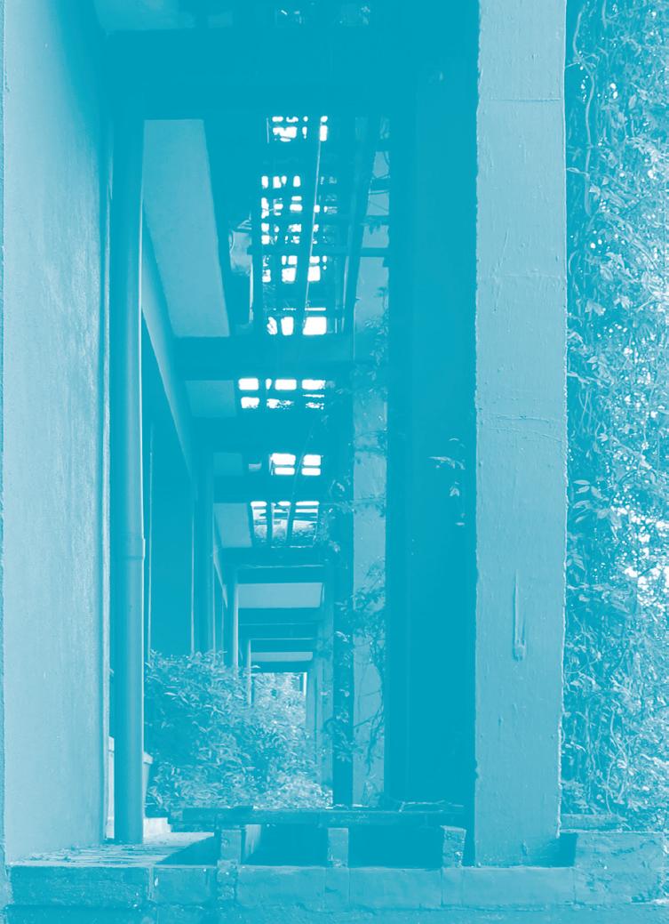
Dambulla, Sri Lanka (1995)
by Geoffrey BawaThe Kandalama Hotel sits in a site of wilderness, against the backdrop of a rock mountain, overlooking the Sigiriya Rock fortress across the Kandalama Lake. The hotel’s formal structure is a combination of parts. Hotel rooms are protected from the elements by layers that are loosely wrapped around the core, to cater to a climate that is hot, wet, and breezy.
The building sits lightly on the natural landscape atop two rows of columns, allowing an unobstructed flow of rainwater down to the lake and to minimize impact on the landscape. These columns form the under layer which cools the building while keeping disruption of the natural site to a minimum.
On the front elevation, the balcony and planter boxes provide a transition space to the exterior. The balco-
nies are separated from the room by a full-height glass door, washing the interiors of the rooms with plenty of natural daylight. A visually porous frame structure made of concrete fronts the balcony. Lush vegetation drapes from the overhanging timber beams and concrete structure above, extending from the overgrown roof to form a natural screen that mitigates glare. The densely planted rooftop garden also absorbs heat and acts as an insulator.
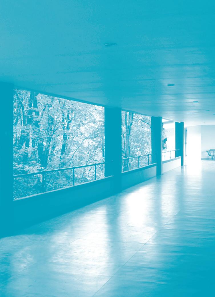
On the other side of the block, a stretch of naturally ventilated verandahs is aligned to the room entrances. The rock mountain behind the building shelters these corridors (Figure 59). As rock has a high thermal mass that efficiently stores heat in the daytime and releases it back at night, the rock formation is cleverly used to convey air movement to passively cool the building (Figure 61a).
Aside from strategies to keep the building breezy and cool, water purification, collection and run-off were
also key motivations of the building. Given that the hotel is situated in a dry climate, flat roofs were material efficient and adequate in receiving rainwater. The roof extended to the edge of the building where planters were located to receive water runoff.

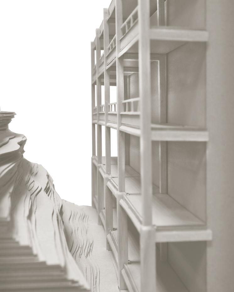
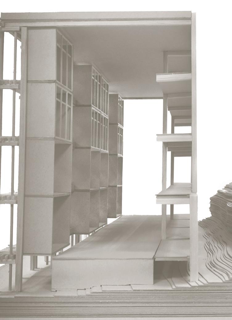
Additional water was treated through natural permeable rock and channelled to the lake. Water used to sustain the hotel activities was pumped up from deep tube wells to ensure safe drinking water.
Weathered Factory Block 55
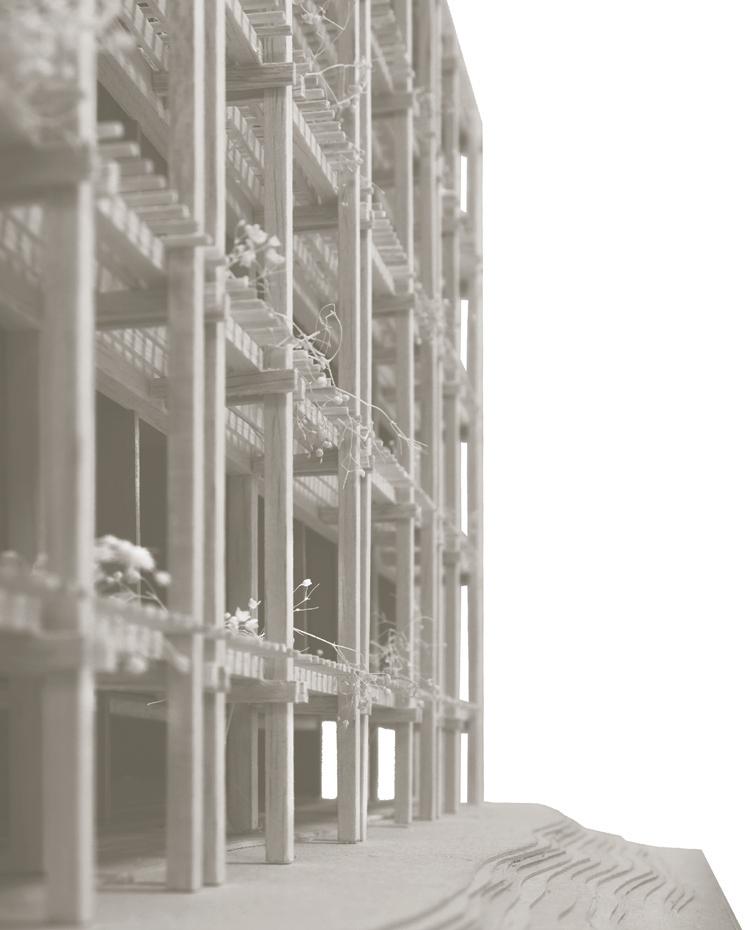
by Leo Huang, Wong May PingThe term ‘weathered’ implies being exposed to the elements, yet it also suggests a toughened exterior, one that has endured the seasons and remains standing. The Weathered Factory is precisely that: a building that changes its patina along with the variegations in climate.
In Singapore there are only two seasons: “hot and hotter.” Projecting this climatic scenario onto the building, the building is subjected to heat, high humidity, and torrential downpours during the Northeast and Southwest monsoon season and on the other extreme, a dry season. The building addresses these two weather conditions, using a living medium of vegetation as its architecture. The result is a façade that transforms and adapts to the two ‘seasons’, blooming in varying shades as it transits between them.
This breathing envelope flourishes in the wet season, blooms when it tapers off and withers in the dry season. The variation in weather conditions controls the atmospheric transformations within the building. In the wet season, the lush green thickens around the building. In transition, as the initial shortage of water kicks in, the flowers bloom in an array of pink and white. In the dry season, the branches grow bare and camouflage with the Corten-steel grid, turning into variant hues of brown and gold. The vegetation significantly thins, but the spatial thickness remains as a sufficient buffer between the building and the elements.
The climatically harsher East and West elevations are furnished with a dense cluster of vegetation (Figure 70). These plants have larger leaves in order to mitigate a higher thermal load and filter out stronger sunlight. Vertical strips of staircases sheltered by planter boxes are designed to sporadically interrupt
this grid. These vertical elements provide visual porosity.
A section of Block 55’s extension (Figure 74) reveals its intricate layering of programs. The office space is projected as a porous mass, interspersed with bands of circulation paths. These communal spaces double as a thermal buffer that prevent direct sunlight and rain from reaching the office area. The innermost layer of the thermal envelope is the corridor that is succeeded by a staircase, held up by the external grid. These two layers provide for horizontal and vertical circulation throughout the building. The outermost layer is a steel grid with planters embedded within. It facilitates physical interaction between users and their natural surroundings. The wide variety of plants are curated for each face of the building ensure a curated aesthetics while adopting functional purposes such as improving indoor air quality or their resistance to dry conditions (Figure 70-72).
The massing of this retrofit project consists of a continuous flow of programs that leads users from the old Block 55 to the new extensions in one smooth transition. The massing is punctuated with pockets of spaces to increase permeability and accelerate airflow through the building. The block facing East is the lowest and contours towards the curvature of the existing Ayer Rajah Crescent road. The block facing West stands slightly higher at 30m and fronts the elevated highway. A cantilever protrudes from the eastern block running along the northern façade, creating a high ceiling over the entrance to the courtyard (Figure 65). This is the highest point in the massing, with a commanding view over the rest of the immediate site.
The Weathered Building is one that will age, die, regrow and change itself continuously. It is a candid reflection of its context , nature, and architecture simultaneously.

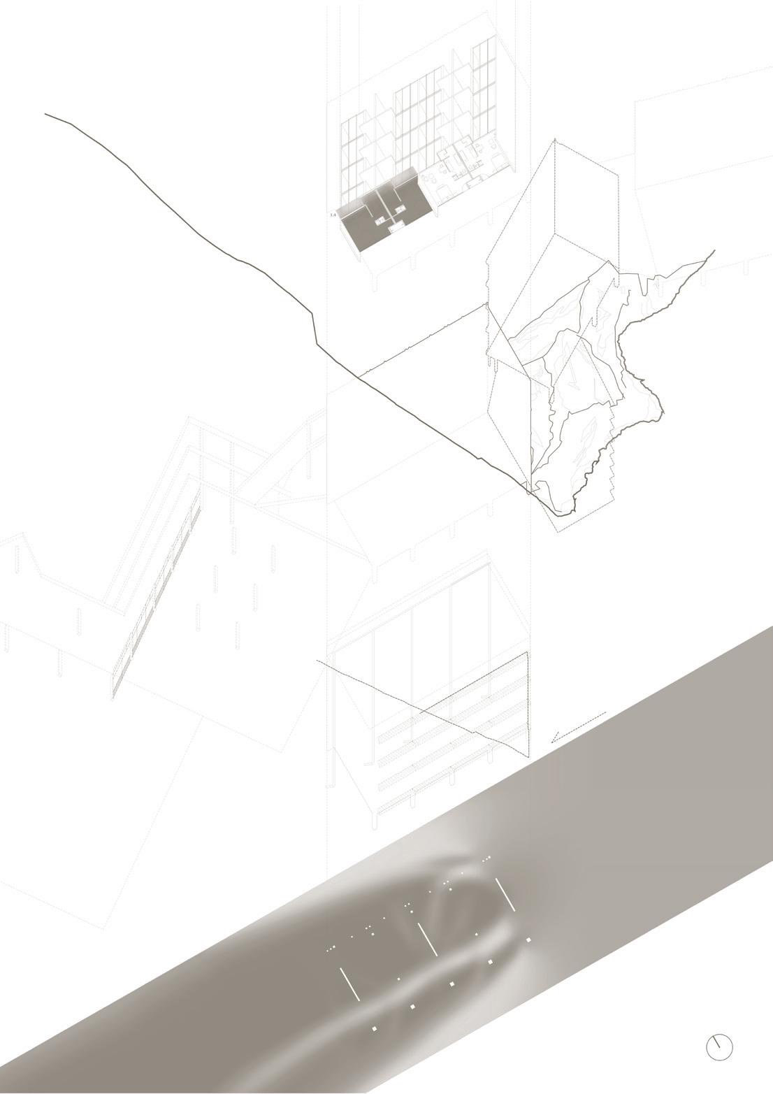 Figure 63: Worm’s-eye perspective of Kandalama Hotel

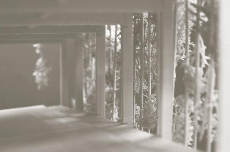
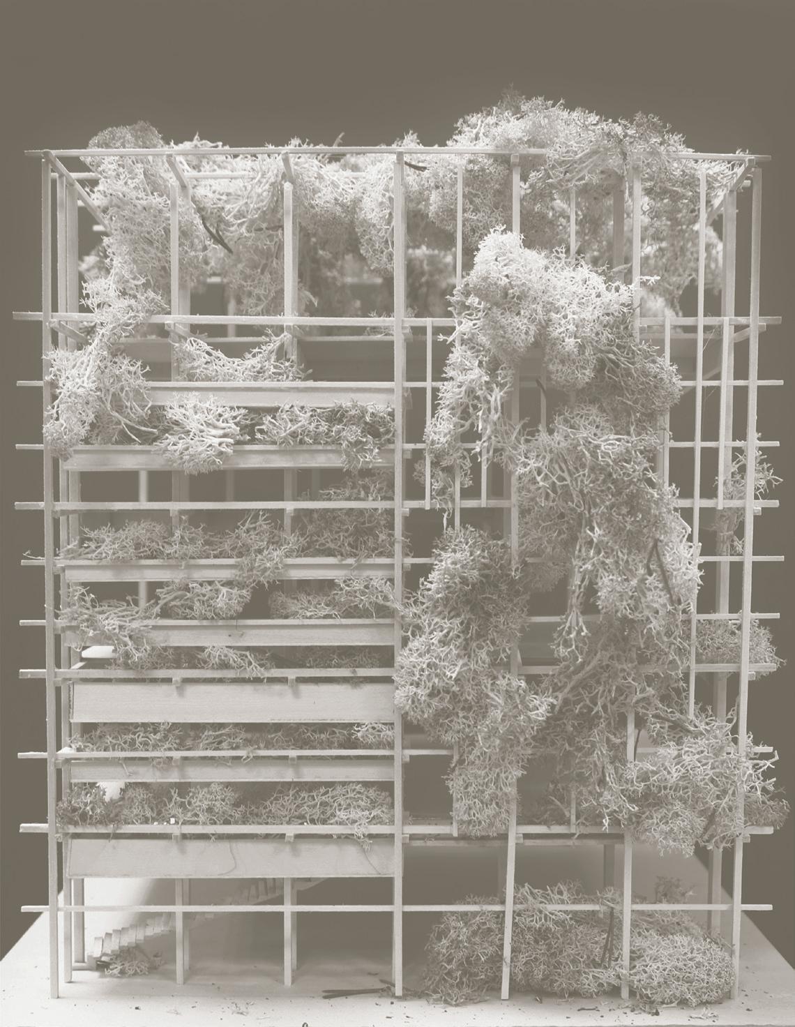
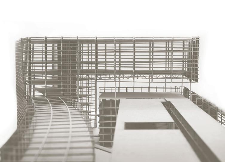
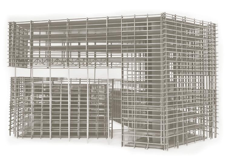
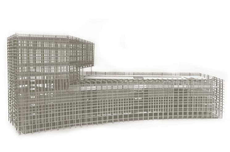
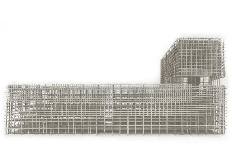
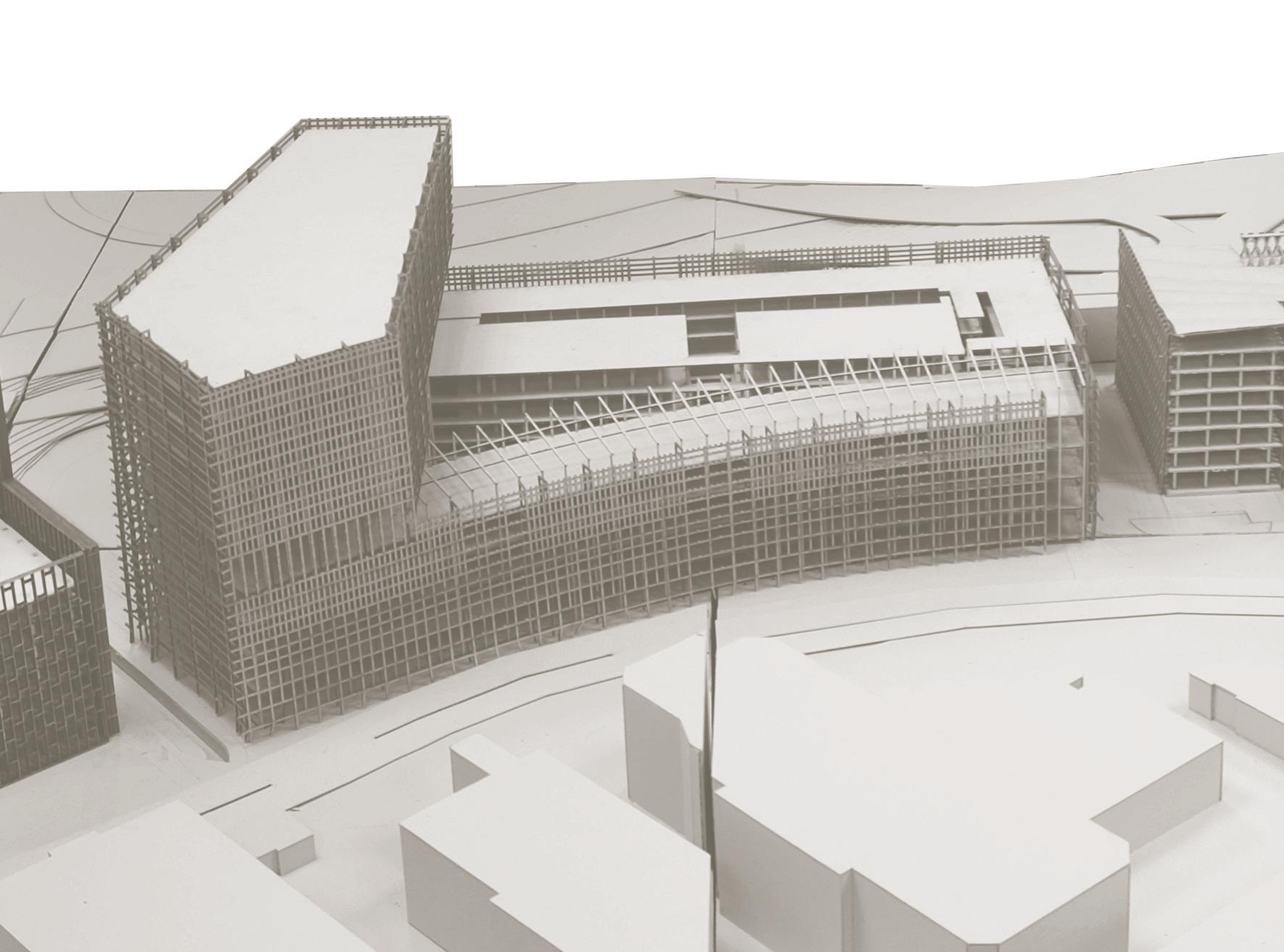
East and West Elevations
Figure 70: The East and West elevations have a combination of plants that would flourish in the wet and dry seasons. These elevations are made more accessible as some plants require more maintenance.
Nassella tenuissima
Grows at fast rate / fine leaves and a narrow inflorescence/ Can withstand dry weather
North and South Elevations
Vernonia elliptica (Bridal Veil)
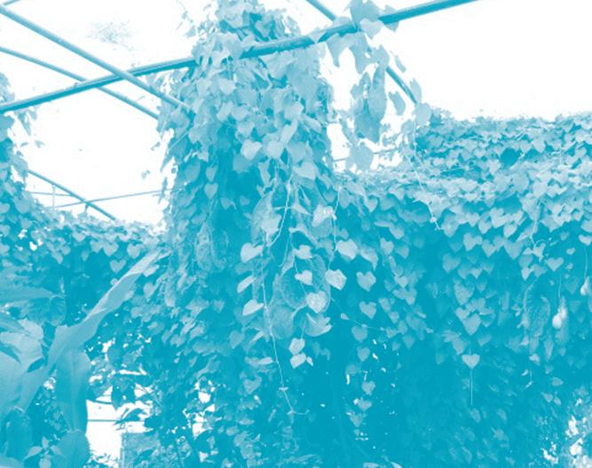
Grows at medium fast rate/ Self trailing/ Robust
Derris trifoliata (Common Derris)
Climbs up to 15m or more / Delicate pale pink flowers / Circular fruits, flat pods
Figure 71: Plants grown on the North and South elevations are familiar house plants that need little maintenance
Dracaena fragrans (Dracaena Corn Plant)

Grows at medium rate / Removes chemical vapours such as formaldehyde



Inner Courtyard Elevations
Peperomia clusiifolia (Red Edge Peperomia)
Grows at medium rate / small/ needs little attention
Chlorophytum comosum (Spider Plant)

Grows at medium rate / Trailing leaves that propogate and beefs up planters
Figure 72: Creepers are grown on the inner courtyard elevations
Aristolochia gigantea (Giant Pelican Flower)
Climbs up to 20m high / Huge flowers up to 30cm long and 15cm wide
Lygodium versteegii
Massive fern climber
Combretum indicum Chinese Honeysuckle
Climbs up to 8m / Elliptical leaves / Fragrant pink + white flowers / Herbal properties

Reference: Tan, P., & Sia, A. (2008). A Selection of Plants for Green Roofs in Singapore. Singapore: CUGE Publications.

