12 minute read
A nexus of clean energy
Bob Oesterreich and Peter Gerstl, Chart Industries, discuss how cryogenic technology is helping to shape the energy transition.
Producing more energy while accelerating efforts to reduce greenhouse gas (GHG) emissions and increasing energy independence is one of the world’s biggest challenges – technologically, politically and economically. This article will discuss how cryogenic technology is helping to shape the energy transition through a nexus of clean energy, comprising
LNG, liquid hydrogen, and carbon capture.
As the cleanest burning fossil fuel, natural gas is often touted as the bridging fuel to net zero. It has increased its share of the global energy mix to almost 25%, predominantly through the displacement of coal. According to data from the International Energy
Agency (IEA), natural gas emits between 45 – 55% fewer GHG emissions than coal when used to generate electricity and, between 2010 – 2018, switching from coal to natural gas-fired power generation prevented 500 million t of carbon dioxide (CO2) emissions from ending up in the atmosphere.¹ Natural gas is also proven in industrial processes; is oftentimes a ‘quick fix’ solution for reducing emissions due to existing infrastructure; and is similarly proven as a transportation fuel for heavy goods vehicles and marine vessels. Further to this, it is a stable support for renewable sources, providing supplementary power generation during peak loading, and when the sun does not shine or the wind does not blow hard enough.
Hydrogen is taking centre stage in many energy roadmaps. With advancements in fuel cell stack technologies and continued cost reductions, hydrogen can be used as an energy carrier to fulfil several roles in the energy sector. With its ability to store renewable power, produce electricity, and power light and heavy-duty vehicles with zero tailpipe emissions, hydrogen has the capacity to be a global energy source at scale.
Traditionally, carbon capture and storage (CCS) has been used as a process to capture CO2 emissions from power generation and industrial processes that burn fossil fuels, compressing the gas and transporting it to areas where it can be injected deep underground. This method is therefore an important step in the decarbonisation of hydrogen that is produced from steam methane reforming (SMR) of natural gas, and coal gasification, which still dominate the energy mix. Blue hydrogen is the term applied to the hydrogen produced following the decarbonisation of grey and brown/black hydrogen.
Carbon capture, utilisation and storage (CCUS) is a further step change in the evolution of carbon capture where, instead of being securely stored as a waste product, CO2 is recognised as a valuable commodity and recycled for uses in many industries such as cement, brewing, and food processing.

Natural gas liquefaction
Natural gas is liquefied through cryogenic processing, reducing its volume to 1/600th of its gaseous equivalent. This makes it easy to transport and store. Until relatively recently, natural gas was predominantly liquefied in ever-larger baseload facilities, and transported across oceans in huge tankers before being landed and regasified for pipeline transmission at similarly large-scale import terminals. The only real exception to this rule are the much smaller peak shavers, which, as the name suggests, were deployed during periods of high load. However, by adapting and refining this small-scale liquefaction approach, a technically-feasible and commercially-viable solution for production and distribution of much smaller volumes of LNG revolutionised the landscape, bringing power to off-grid locations and providing an alternative transport fuel for trucks, ships, and even railway locomotives.
The key to the success of small-scale LNG is bringing gas to the market quickly, as well as simple plant operation. As a result, instead of a bespoke, custom design every time, a major feature is a range of standard, repeatable-design liquefaction plants. This significantly reduces the project timescale and delivers lower CAPEX. Small-scale cryogenic liquefaction plant sizes typically range from 15 000 gal./d (25 tpd) through to 450 000 gal./d (720 tpd), where the larger plants (50 000+ gal./d) are predominantly aimed at liquefaction of pipeline gas for virtual pipeline solutions, and plants below 50 000 gal./d are often applied to liquefaction of waste methane to produce liquified biogas (LBG). As with their much larger counterparts, there is also a choice of liquefaction technologies through mixed refrigerant processes, as well as the Reverse Brayton Nitrogen Cycle.

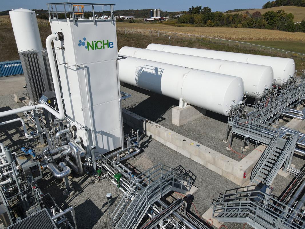
Figure 1. A small-scale LNG liquefaction plant in Pennsylvania, US, produces LNG for the local merchant market.
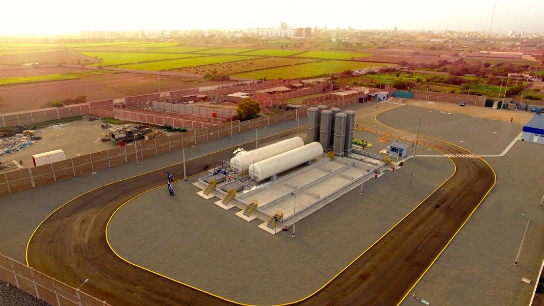
Figure 2. A series of small-scale LNG regasification facilities in Peru store LNG and provide natural gas to homes and businesses that previously used oil-based and wood fuels for heating.

Modular mid-scale LNG
The concept of modular mid-scale LNG is best demonstrated by the liquefaction plants that export large quantities of North American shale gas. Instead of a single, large, custom-built facility, total plant capacity is achieved through a series of replicable modules. For example, a plant with a total liquefaction capacity of 12 million tpy could be achieved through six identical 2 million tpy modules or 12 identical 1 million tpy modules. By using proven, standard equipment packages, maximising shop build and minimising onsite construction, the chief advantages of the modular approach are: � Reduced overall project timescale. � Lower risk profile. � Modules that can be brought online and operated independently for earlier revenue recognition. � The ability to respond more quickly to demand fluctuations.
Small-scale LNG regasification
The concept of trucking liquid fuel to areas or facilities not connected to a pipeline grid is familiar to many through diesel, heavy fuel oil (HFO) and other distillates. Small-scale LNG regasification essentially uses the same model. The only difference is that the liquid fuel being transported is natural gas. A regasification station, also referred to as an LNG satellite station, incorporates storage, vaporisation, pressure regulation, and control systems to deliver natural gas exactly as if it were from a physical pipeline.
Small-scale LNG regasification is widely used to bring power to off-grid and remote locations, and provide LNG as a vehicle fuel. It is also an excellent solution to augmenting pipeline natural gas instead of oil-based fuels, as it utilises the same delivery system to the point of use as the pipeline gas.
Virtual pipeline
Where no physical pipeline for delivering natural gas exists, the process of delivering LNG from its source to the point of use by sea, road, rail or a combination of one or more of these, in cryogenic containers, is called the virtual pipeline.
Small-scale import terminals
To compete with the economies of scale afforded by their much larger counterparts, small-scale import terminals have to provide a multi-function approach and respond quickly to demand fluctuations. The import terminal in Klaipeda, Lithuania, is a good example of this approach, where offloaded LNG can be used for marine bunkering,
loaded into road tankers for virtual pipeline distribution, or regasified for pipeline transmission.
Small-scale terminals also share many design and production features with their liquefaction plant counterparts. Shop-built equipment reduces cost and schedule, and modular construction reduces civil work and facilitates faster installation. Replicable modules also mean that potential future capacity expansions can be incorporated into the base design. Another good example of a single-use, small-scale import facility is in Gibraltar, Spain. The 80 MW gas-fired power station is fed by a shore-built import terminal with 5000 m³ of LNG storage. Bunkering terminals for marine fuelling are a further example of small-scale regasification in action.
The liquefaction of hydrogen produced from low-cost sources will allow for the storage and transportation of hydrogen energy all over the world, using a supply chain very similar to how the LNG supply chain is structured today.
Using LNG as the basis for developing global hydrogen supply chains
Not everything associated with hydrogen is ‘new’ or ‘novel’. In fact, liquid hydrogen products have been proven in use over decades, supporting a range of local markets and industrial applications, as well as launching satellites into space. It is the globalisation of liquid hydrogen that will require large-scale transportation systems that are used with LNG, and that extensive LNG experience can be applied to, for example, liquid export and import terminals, bunkering systems, and cryogenic transport trailers and ISO containers for road, sea and rail.
All the way along the value chain, there are examples of increased demand for natural gas leading to developments in the capacity and capability of LNG equipment. As both LNG and liquid hydrogen are stored and transported in insulated vessels, many of those developments are directly transferable, and mean that the hydrogen infrastructure can similarly be expanded through shop-built, reliable and proven equipment.
One of the main features of hydrogen is its ability to store and produce electrical energy, enabled through the use of fuel cell technology. Fuel cell engines convert pure hydrogen into electricity through an electrochemical process without generating CO2 as a byproduct. This results in zero carbon emissions in the power generation process. Applications using natural gas or LNG to produce electricity or motive power require the combustion of natural gas, resulting in CO2 emissions at the point of use in the power generation process. As discussed earlier in this article, natural gas and LNG offer the ability to reduce emissions compared to gasoline or coal in power generation or transportation. Producing hydrogen from natural gas, renewable natural gas (RNG) or renewable energy using fuel cell technology can reduce carbon emissions even further. In addition to the carbon and emissions reduction benefits of natural gas in internal combustion engines (ICEs), and hydrogen and fuel cell technology in fuel cell electric vehicles (FCEVs) for the power generation and transportation markets, fuel cell technology is more efficient in the conversion to
Proven Zero Leakage Isolation V Series with RiTech® H for Hydrogen Service
• API 622 / ISO 15848-1 certified fugitive emissions stem packing • Integral metal seated • Specialized coating processes • Fire Safe per API 607
Engineered with High Velocity Oxygen Fueled Coating Technology


Figure 3. LNG bunkering terminal for fuelling ships in Jacksonville, Florida, US.
electrical energy as compared to the traditional combustion technologies primarily used today.
When comparing the GHG emissions and energy efficiencies for natural gas and hydrogen to conventional gasoline, while liquid hydrogen has outstanding value regarding its gravimetric energy density, its volumetric energy density is very low compared to LNG, thus pushing the demand for larger volumes of storage tanks.
Furthermore, hydrogen is a much smaller molecule than natural gas, and components that are tight under natural gas services might leak in hydrogen service. Liquid hydrogen boils at -252.8˚C (22.3 K). Only liquid helium has a lower boiling point. Due to this, the cold temperatures of liquid hydrogen carry the potential of liquefying air and generating oxygen-rich condensates where the cold energy meets normal air. As such, the choice of potential refrigerants for a hydrogen liquefaction process and of purge gases for such cryogenic process units is extremely limited. The critical point of hydrogen is at 12.97 bar(a), above which it is a one-phase fluid and only has 50% of the density of cold liquid. Besides these fundamental characteristics, liquid hydrogen and gaseous hydrogen have other physical properties which need to be considered for all hydrogen equipment design and manufacturing in order to ensure safe and reliable operation.
Hydrogen can be liquefied by using either open-loop pre-cooling with liquid nitrogen (LIN) or with closed-loop pre-cooling. The first approach is typically used for smaller liquefiers, and where CAPEX is key to economic success and LIN is available at lower costs.
The second is more attractive for larger-scale liquefiers as the additional CAPEX is comparably small, but the effort for providing large amounts of LIN would be tremendous. The typical range for the required electrical power consumption starts from 7.5 kWh/kg for the open-loop process and from 10 to 15 kWh/kg for closed-loop processes. As with natural gas, hydrogen can be liquefied at a large, centralised production source and transported locally and globally, allowing it to be exported from geographies with low-cost production to the markets it serves. Some examples include: � Green hydrogen can be produced via electrolysis in geographies where there is an abundance of wind and solar energy. � Blue hydrogen can be produced in geographies with low-cost natural gas via steam methane reformation and carbon capture.
The hydrogen gas produced from these sources can be liquefied, stored and transported into the markets as a low or zero-carbon electrical energy source for transportation or power generation. As with LNG, liquid hydrogen can be transported by truck, rail or water from regions with low-cost hydrogen production into regions with a demand for low-carbon energy feedstocks for transportation or power generation.
CCUS
Today, 10 million tpy of hydrogen capacity exists in the US, with most of that being grey hydrogen produced from natural gas. CCUS will play an important role in reducing carbon emissions and the transition to blue hydrogen playing a key role in the energy mix. A large concentration of the US-based hydrogen plants are located on the Gulf Coast, currently providing hydrogen for processing crude oil into transportation fuels. As the dependence on fossil fuels decreases, this hydrogen capacity can be used for other purposes such as mobility applications. Additionally, some of this hydrogen could be used for chemical applications, as well as hydrotreating in renewable diesel production facilities.
Technologies are being developed and demonstrated for the production of different colours of hydrogen. There has also been a huge uptick in carbon capture, both on a large-scale and, equally importantly, for smaller-scale solutions and retrofits to decarbonise existing facilities and industries where the captured CO2 is used in the production process. As well as creating blue hydrogen, the importance of CO2 as a valuable commodity was perfectly demonstrated in late summer in the UK when its main producer stopped work. This resulted in a cut of 60% of the UK’s food-grade CO2 supply. Production at the fertilizer plant, where the CO2 is produced as a byproduct, was only restarted after the government stepped in and agreed a price five times higher than it was previously.
Conclusion
There is significant evidence that the model for LNG can be applied to the liquid hydrogen value chain, further enabling hydrogen to play a significant part in the world’s sustainable energy future. Liquefaction processes were developed in the middle of the previous century and there are multiple, proven processes that are being further optimised for larger capacity liquefaction facilities. A lot of the key capital equipment is the same for natural gas and hydrogen liquefaction, and has been proven over many decades. Similarly, liquid hydrogen vessels and trailers, used for storage and transportation, are well-established across multiple cryogenic services, including hydrogen, and in applications such as high-tech manufacturing and aerospace, where quality is paramount. In summary, the cryogenic technology at the heart of LNG is uniquely positioned to play a key role in the build-out and scale-up of the global liquid hydrogen chain, and can also be applied to its decarbonisation.
Reference
1. ‘The Role of Gas in Today’s Energy Transitions’, IEA, (July 2019), https://iea.blob.core.windows.net/assets/cc35f20f-7a94-44dca750-41c117517e93/TheRoleofGas.pdf


