
11 minute read
An Industry Co-Production
AN INDUSTRY AN INDUSTRY
CO-PRODUCTION CO-PRODUCTION


Julie Ashcroft, Johnson Matthey,
UK, explores the technologies that have been jointly developed to enable ammonia and methanol co-production as well as retrofits of ammonia plants.
The production processes for the manufacture of ammonia (NH3) and methanol (CH3OH) are similar in the goal to manufacture syngas as an intermediate prior to the fi nal product, with the processes sharing key upstream unit operations. To develop these synergies, Johnson Matthey (JM) and Kellogg Brown Root (KBR) have formed an alliance to offer co-production standalone fl owsheets and retrofi ts of ammonia plants to incorporate a methanol production section.
Both standalone methanol and ammonia plants contain natural gas feedstock purifi cation units and steam methane reformers (SMRs). The gas stream exiting the SMR contains syngas, a mixture of hydrogen (H2) and carbon oxides (CO and CO2). In conventional methanol plants there is excess hydrogen in this gas stream, and in ammonia plants the carbon oxides present are not required for ammonia production and can act as poisons to downstream catalysts.
After leaving the SMR in a methanol plant, the syngas mixture passes through a methanol synthesis converter loop prior to a separation stage.
For ammonia production, the gas stream exiting the reformer section passes through a secondary reformer, where air is added. The gas stream then undergoes water-gas shift to reduce the level of carbon oxides, before these are removed in the carbon dioxide removal section, with residual carbon oxides being converted to methane (CH4) in the methanator before passing into the ammonia synthesis loop.
Benefi ts of co-production
The benefi ts of co-production stem from the different requirements of syngas from each process. In methanol


production, the reaction can be summarised as one mole of carbon monoxide reacting with two moles of hydrogen to give one mole of methanol (Equation 1).

CO + 2H2 CH3OH Equation 1
However, steam methane reforming generates hydrogen and carbon monoxide in a ratio of 3:1 (Equation 2), resulting in one mole of hydrogen in excess. This is typically used as a fuel source for the SMR in standalone methanol plants.

CH4 + H2O CO + 3H2 Equation 2
In ammonia production, the presence of carbon oxides is a concern. The species are not required for ammonia generation, and carbon oxide and carbon dioxide are poisons to ammonia synthesis catalysts. As such, a signifi cant section of the ammonia production process is dedicated to removing carbon oxides from the gas stream. The water-gas shift reaction (Equation 3), taking place in the high- and low-temperature shift sections, is benefi cial in generating more hydrogen as it converts carbon oxide to carbon dioxide; however, the methanation section uses up hydrogen in removing the residual carbon oxides from the gas stream (Equations 4 and 5). The dedicated carbon dioxide removal section is energy-intensive.

CO + H2O CO2 + H2 Equation 3
CO + 3H2 CH4 + H2O Equation 4

CO2 + 4H2 CH4 + 2H2O Equation 5
Methanol production, on the other hand, requires the presence of carbon oxides in the gas stream, and has been used in coal-based ammonia synthesis as a carbon dioxide removal step. Combining ammonia and methanol production into one plant can allow the excess carbon dioxide to be used as a methanol feedstock.
There are numerous approaches to ammonia-methanol co-production that utilise the different hydrogen and carbon oxide requirements for each section; new projects can look to design a standalone process that can vary production between ammonia and methanol (depending on demand), whilst retrofi ts to ammonia plants will be driven by the desired methanol production rates.
Standalone co-production unit
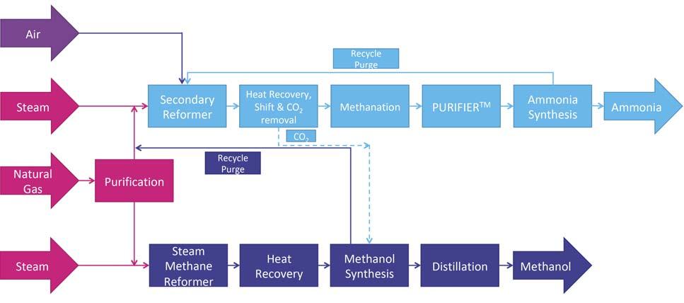
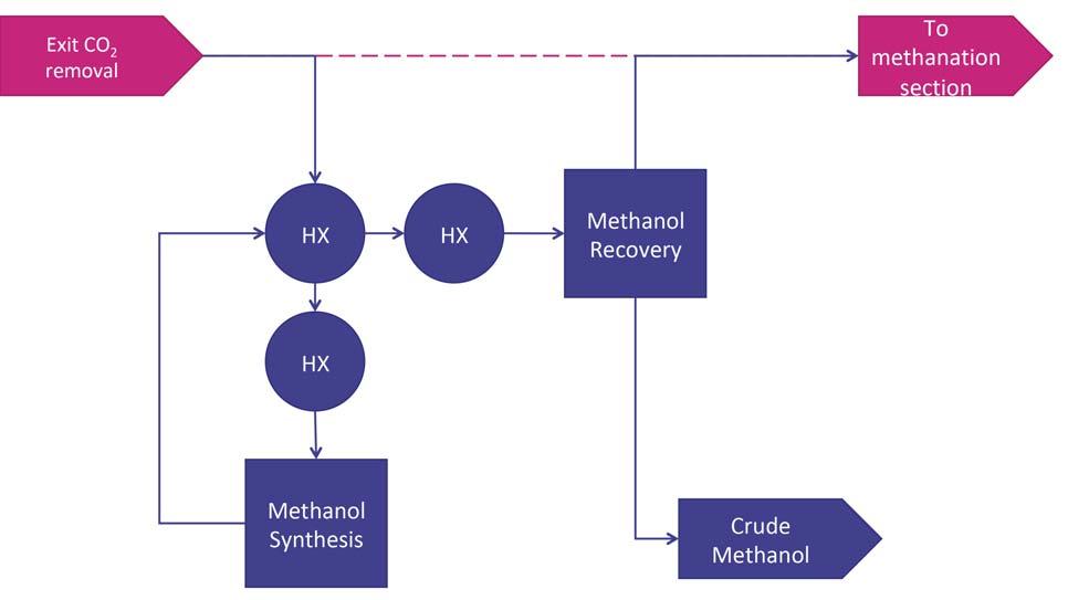
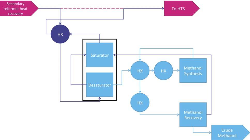
For companies considering a new-build ammonia or methanol plant, a co-production unit – as shown in Figure 1 – gives fl exibility of production and better utilisation of the syngas generated within the plant. Compared to a standalone ammonia unit, the ammonia section of the co-production unit does not contain a primary reformer, with hydrogen being provided from secondary reforming of natural gas and from the hydrogen-rich methanol synthesis loop purge. There is a reduction in size of the Figure 1. Ammonia methanol co-production flowsheet, showing the hydrogen-rich recycle carbon dioxide removal system and the energy demands are reduced, as purge from the methanol section being used as feedstock for the ammonia section. the use of the methanol section purge gas to provide hydrogen reduces the carbon dioxide content of the syngas in the ammonia section. The methanol section remains similar to a standalone unit, with the exception of some shared/integrated equipment and the possibility to utilise carbon dioxide removed from the ammonia unit as additional feedstock. Within the ammonia section, the use of the KBR Purifi erTM process is key to operating the secondary reformer with excess of air. This provides additional reaction heat, removing methane Figure 2. Methanol co-production retrofitted to an ammonia flowsheet, with the carbon oxides provided by the gas stream inlet the HTS reactor. and other inerts from the syngas before entering the synthesis loop and maintaining the 3:1 H:N ratio required by the ammonia synthesis loop, which in a standalone ammonia plant would be controlled by limiting the airfl ow into the secondary reformer. In this application, a cryogenic unit is used to purify syngas and achieve the 3:1 ratio before entering the ammonia synthesis loop. The removal of excess nitrogen and the high purity of stream are important for the co-production unit. There is suffi cient fl exibility in the fl owsheet to manufacture a wide range of ammonia:methanol production ratios, with a maximum Figure 3. Methanol co-production retrofitted to an ammonia flowsheet, with the carbon production rate of 6800 tpd. The oxides provided by the gas stream exit the CO2 removal stage. process is designed in such a way
that any production issues affecting one product do not impact the other.
In addition to the inherent fl exibility of the co-production process, there are further benefi ts over standalone ammonia and methanol plants. There are fi nancial benefi ts – CAPEX for a co-production unit is reduced by 15 – 25% when compared to separate standalone ammonia and methanol plants, while OPEX is also reduced due to the improvement of feed and energy effi ciencies within the integrated process streams when compared to separate standalone plants.
There is also a signifi cant reduction in carbon dioxide generated per tonne of ammonia, due to purge gas from the methanol section providing a large proportion of hydrogen feedstock for ammonia production, rather than generating further hydrogen via the SMR.
Additionally, the co-production unit does not require pure oxygen, due to JM’s knowledge in developing large-scale SMRs. This removes the requirement for an air separation unit (ASU) which, in turn, improves safety and reliability.
Ammonia plant retrofi ts
Retrofi ts to ammonia plants utilise the levels of carbon oxides in process gas to produce a desired level of methanol. The level of methanol production required will determine where the gas stream will be redirected from the ammonia plant. For high levels of methanol production, the gas stream inlet to the high-temperature shift (HTS) reactor will be directed to the methanol section, as shown in Figure 2. For lower levels of methanol production, the use of syngas exiting the carbon dioxide removal system provides suffi cient carbon oxide levels, outlined in Figure 3.
Retrofi t using syngas inlet-HTS reactor
The recommended case for higher production rates of methanol, using syngas from the HTS-inlet stream, has the benefi t of a relatively high fraction of carbon oxides. However, due to a relatively high level of water in the gas stream, the syngas must fi rst pass through a desaturation step to reduce the water content. The gas stream then passes through a once-through converter to produce methanol, which is then separated from the gas stream in a recovery step, giving crude methanol that can be sent to a distillation stage to achieve the required product quality. As there is a single connection point between the ammonia plant and the retrofi t, the ammonia plant can continue operations whilst the methanol unit is shut down.
Due to the nature of the retrofi t, the syngas will enter the methanol section with a very high fl owrate due to a high concentration of nitrogen. As a result, a once-through methanol reactor is preferred to a synthesis loop in order to minimise the capital cost of the unit.
The addition of a retrofi t at this point in the plant will result in a reduction in ammonia production rates, as a proportion of hydrogen is used in the methanol section rather than in the ammonia synthesis loop. If this is a concern, there is the potential to uprate the front-end section of the ammonia plant to offset some or all of this loss in production.


LEADING PROCESS TECHNOLOGY FOR OUR FUTURE
www.borsig.de/pro
BORSIG Process Heat Exchanger GmbH
Phone: +49 (0)30 4301-01 Fax: +49 (0)30 4301-2447
The methanol unit will change to H:N ratio from the required 3:1 ratio required by the ammonia synthesis loop. This can be addressed through optimisation of the reforming section or through use of the PURIFIER process, as discussed in the standalone co-production section.
Retrofi t using syngas exit-CO2 removal
The process is similar to the inlet-HTS retrofi t described earlier; however, the concentration of water in the syngas at this stage is low enough to remove the saturator and desaturator unit operations. The gas passes through a once-through methanol reactor, before crude methanol is isolated in the methanol recovery stage. The remaining syngas is then returned to the ammonia plant and enters the interchangers prior to methanation. As with the inlet-HTS retrofi t, there is a single connection point between the ammonia plant and methanol section.
There are substantial benefi ts to a retrofi t of this nature, which include a potential boost in ammonia production. In a standalone ammonia plant, carbon oxides at this stage enter the methanation section where they react with hydrogen to produce methane and water. This is required, as carbon oxides are poisons to the ammonia synthesis catalyst. However, each mole of carbon oxide and carbon dioxide uses up three and four moles of hydrogen respectively (see reactions 4 and 5). When these carbon oxides are instead used for methanol production, each carbon oxide reacts with two and three moles of hydrogen respectively, resulting in an increase in hydrogen entering the ammonia synthesis loop.
Methanol applications
Depending on the end use of the crude methanol, it can be sent to a distillation stage to reach the required quality level for selling or the crude methanol can be used as a feedstock for formaldehyde production. This would be suitable for sites manufacturing granular and certain types of prilled urea products, where urea formaldehyde concentration (UFC) is used to condition these products.
In the integrated UFC (iUFCTM) process, the methanol section retrofi t is combined with a downstream JM FORMOXTM plant that uses the crude methanol as a feedstock for formaldehyde production, allowing the plant to manufacture UFC to the desired concentration.
The rate of methanol production is typically suffi cient to support a production rate of UFC that matches the site requirements, allowing the site to be self-suffi cient in UFC supply and no longer have to import UFC from a third party. The key benefi t of in-house production of UFC is a reduction in cost versus imported UFC, which is priced at a premium to cover the cost of feedstock, transportation and margins for the producer. The potential savings are dependent on the circumstances of each individual producer, but can be in the region of the current purchase cost of UFC.
Conclusion
The fl exibility of production of a wide range of ammonia and methanol ratios can be advantageous, as it allows plants to respond quickly to any changes in market dynamics and product demand. With various options available, from a standalone co-production unit or a retrofi t to an existing ammonia plant, the technologies outlined in this article are applicable to most ammonia producers.
In addition to the general benefi ts outlined, site specifi c benefi ts and potential savings can be assessed for individual plants. Large-scale co-production in a single train can be achieved for new plants and retrofi ts can allow for signifi cant methanol co-production, providing a high degree of fl exibility and operational savings. Retrofi ts can also allow a plant to become self-suffi cient in UFC production and reduce the costs associated with UFC procurement.


