
16 minute read
Energy-Efficient Sulfuric Acid Cooling
ENERGY-EFFICIENT


Nelson Clark, Breno Avancini and Vitor Sturm, Clark Solutions, Brazil, examine a new technology designed to safely cool strong sulfuric acid and reduce heat loss.


SULFURIC SULFURIC Acid Cooling Acid Cooling
Sulfuric acid plants must utilise acid cooling and energy recovery effectively. Strong acid cooling, paired with energy recovery, is not yet a widely accepted practice, though interest has been growing since the 1980s. There have been some proven technologies employed, but the associated risks – hydrogen corrosion, heat generation or high temperatures – have limited their acceptance and spread. To eliminate these risks, Clark Solutions has developed the SAFEHR® heat recovery system for use in 150 tpd acid plants; it can replace conventional heat exchanger systems, providing protection against corrosion and hydrogen incidents while recovering energy. The system has been supplied to a new plant being constructed that will process 3200 tpd.
The subsequent development of the SAFEHX® heat exchanger system resulted from the company’s interest in enhancing process capacity and effi ciency through cost-effective approaches. This article discusses a novel technology that switches from sensible heat to latent heat while merging both heat exchangers into one. In addition to increasing cost-effectiveness, SAFEHX has shown a number of benefi ts. As well as sulfuric acid plants, this technology can be used in other industries due to its innate temperature control and strong resistance to fouling. A pressure dominant system results in this temperature control, since the shell buffer fl uid operates in a boiling-condensing regime. This means that cold fl uid will not exceed the set buffer temperature.
SAFEHR has a wide range of potential applications (boiler feed water [BFW] heating, steam production, service water heating, conventional cooling, etc.) while SAFEHX offers a compact, precise and robust approach to heat transfer. In this heat exchanger design, an inert fl uid is enclosed in the middle of a three-fl uid heat exchanger. Bottom tubes carry hot fl uid while top tubes carry cold fl uid, with buffer inert fl uid constantly boiling and condensing to transfer heat between them. Shell side inert fl uids serve as temperature buffers, reducing the potential risks of top and bottom fl uid mixing.
In this article, prototype results are shown that demonstrate a safe and cost-effective technology. The benefi ts of SAFEHX are applicable to virtually any heat exchanger system where corrosion hazards, mixture risks, fouling, process liquid loss (or contamination) and temperature control are key issues.
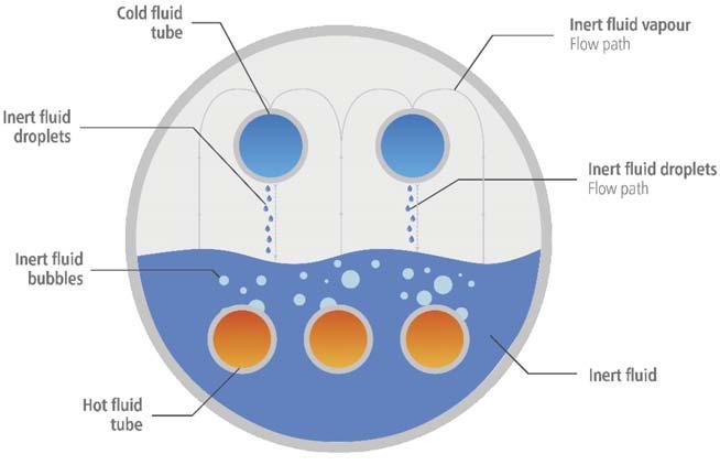
Figure 1. Basic SAFEHX operating scheme.
Design
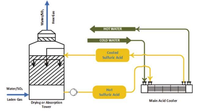
Figure 2. Conventional acid cooling (rejecting heat to cooling water).
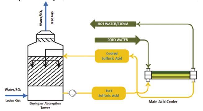
Figure 3. SAFEHX acid cooling (heat can be transferred to cooling water, BFW or elsewhere).
Figure 4. Immiscibility and inert aspect (left: sulfuric acid and fl uid; middle: fl uid and water; right: sulfuric acid, fl uid and water). SAFEHX uses a mutually inert buffer fl uid as part of the cooling of hot acid or another fl uid, inside a three-fl uid heat exchanger. A shell and multiple bundles of tubes make up the design. In contrast to the upper tubes – which reclaim heat and condense the buffer fl uid – the bottom, submerged tubes provide heat to boil the buffer fl uid. The boiling-condensing regime generates buffer fl uid fl ow within the shell. Utilising a compact device based on latent heat, it maximises heat transfer safety and reliability, minimises damage due to hot and cold fl uid mixing and eliminates hydrogen production and accumulation in the event of a leak. Figure 1 illustrates a basic SAFEHX operating scheme. In this system, an inert fl uid is used as a thermal buffer inside a single heat exchanger. Sulfuric acid plants cool hot acid in the bottom tubes by boiling an inert fl uid, the vapours of which are then condensed when BFW or another fl uid is heated. Tube bundles do not require attention when it comes to fl ow direction, so connection and piping interferences are reduced. By eliminating shell baffl es, the equipment is easier to manufacture and maintain as well as being cost-effective. SAFEHX can be used in a conventional acid cooling system (Figure 2) or be attached to a heat recovery tower as a safety and reliability aid. Figure 3 shows how the technology would be integrated within the absorption tower; almost no change is required to install the equipment.
Inert fl uid
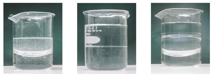
Clark Solutions has performed extensive testing and evaluation of direct cooling of sulfuric acid by mixing with inert fl uids
since the early 2000s (Figure 4). A few fl uid families with the proper properties were identifi ed from this research: Stability: fluid can withstand processing temperature and pressures. Inertness: fluid must be inert in both hot and cold fluids, e.g. acid and water. Flammability: fluid had to be non-flammable. Toxicity: entirely non-toxic. Corrosivity: fluid cannot be corrosive to steel and other alloys. Safe to handle: minimal or no handling or special storage requirements. Density: fluid density that is better in between water and acid densities; in the event of a leakage of both water and acid, the fluid would be between both and would minimise the contact of the fluids, preventing heat generation and weak concentration. Heat transfer: good heat transfer properties. The direct contact approach failed; the amount of fl uid required would be substantially higher than desirable, the fl uid’s fi nal temperature would be much lower than the acid temperatures – impeding any heat recovery – and the potential loss of fl uid due to acid carryover on the acid stream could be costly.
The direct cooling approach proved to be unattractive from a commercial standpoint, but the inert fl uid was deemed to be suitable for a trim cooling system, which led to the development of SAFEHR.
Similar characteristics were relevant for SAFEHX, but different vapour pressures were needed. However, different vapour pressures would simply require operating with different pressures. The benefi t of effectively controlling temperature was evident from this.
A cooling process may utilise different buffer fl uids that interact better with hot or cold fl uids specifi c to that process.
Safety and hydrogen incidents
When an acid cooling system is used in a plant without a recovery system, the fl ow of acid through the acid coolers is accomplished by a high acid pressure over the cooling water pressure. If an acid leak occurs, it will usually be detected by measuring the pH of the contaminated water downstream from coolers instead of dilute acids forming inside the plant equipment. Heat transfer equipment and cooling water systems will be severely damaged by leaks, and any subsequent plant shutdown may last between days and weeks depending on the leak extent.
In a heat recovery system, acid is always under a lower pressure than boiling water, which is under a pressure of up to 10 bar, according to steam quality requirements. The large pressure difference between acid and water is a stronger driving force than the pressure difference in a conventional system. As a result, leaks resulting from corrosion, poor materials and workmanship quality, or even stress issues, will occur at fl ow rates that are substantially higher than those
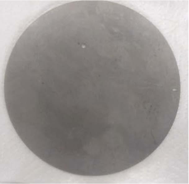
Figure 5. 316L plate in acid/inert fl uid system (left); 316L plate in acid/water system (right) – note that a hole was used to mix fl uids and represent a mild leak in initial ambient temperature. experienced in a conventional system. The results will be an increase in acid dilution and temperature rise and, ultimately, critical failure. Aside from hot water, the leak area receives hot acid at temperatures in excess of 180˚C, which is mixed with water to produce diluted acid at even higher temperatures. The local environment is extremely aggressive. A study by the company of dilution-induced corrosion progression demonstrated that a 1 mm hole in an acid/water system can corrode 150 mm per year at an ambient temperature and pressure, with the hole diameter growing by as much as 0.1% per hour under these mild conditions (Figure 5). Using an inert fl uid greatly reduces corrosion rates, even if a leak occurs. Table 1 shows the results measured from these corrosion tests. When a water leak into the acid occurs in a heat recovery system, the strong acid in the system will be diluted. The corrosion effects will occur inside acid plant equipment and hydrogen will accumulate in high spots. Several hydrogen explosions have been reported by the industry in the recent past. Fe0 (s) → yields Fe2+ (aq.) +2e2H+ (aq.) +2e→ yields H2(g)↑ (1) A number of actions and measures have been taken to minimise the risk of a disastrous failure in a heat recovery system due to leaks of hot high-pressure water into acid.
Table 1. Sulfuric acid corrosion progression on leaking hole Fluid pair Conditions Results
Water 98% sulfuric acid 12 hours duration Start at ambient temperature 316L stainless steel apparatus Corrosion rate: 145 mm/yr Mass lost: 0.1% per hour CS270 inert fluid 98% sulfuric acid 72 hours duration Start at ambient temperature 316L stainless steel apparatus Corrosion rate: nil Mass lost: nil
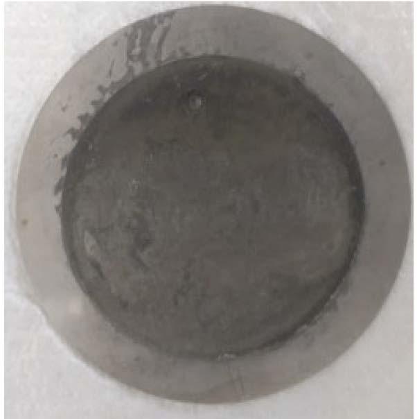
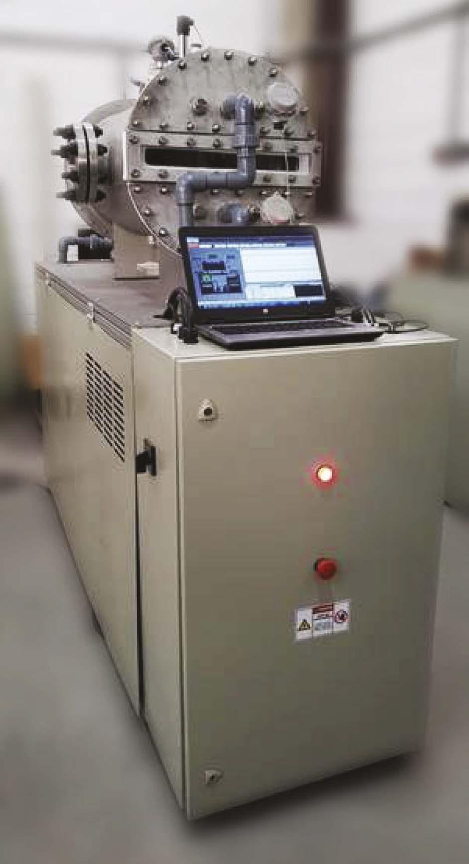
Figure 6. Physical experimentation bench.
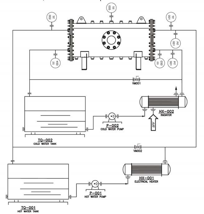
Figure 7. Experimental bench basic flow diagram.
Modern, sophisticated and redundant concentration, corrosion and temperature digital monitoring and control, as well as segregated heat recovery towers, have been employed to reduce the probability of emergency shutdown. Advances in instrumentation have also substantially reduced risks through monitoring and safety measures. However, none of these safety schemes eliminate the root cause of the failure: acid-water contact. SAFEHR and SAFEHX do not allow the mixing of acid and water.
Prototype
Using heat and mass transfer models, a rigorous numerical analysis was conducted to size the prototype of SAFEHX.
Using the results obtained from this numerical study, Clark Solutions’ engineering team designed a mechanical project, an experimental bench set-up and an automation system to validate the results quantitatively.
Figure 6 shows the experiment bench. It had two pumps, two volumetric fl owmeters, fi ve thermistors and three pressure transmitters. Data acquisition and bench control were handled by the PLC and supervisor system. The supervisor system was operated by a computer, which was used for bench control.
Looking at the basic fl ow diagram of the bench in Figure 7, it can be seen that it has two closed-loop water cycles. One is called the cold water loop, which has a tank, a pump, a fl ow control valve, one pressure transducer, two temperature transducers and one air radiator to decrease water temperature. The other is the hot water loop. This other loop also has a tank, a pump, a fl ow control valve, one pressure transducer and two temperature transducers, but it has a heat resistance system instead of an air radiator to increase water temperature.
Experimental results
The company conducted a variety of bench tests to verify that the instrumentation and heat transfer system worked as expected, before performing some prototype runs to verify its effi ciency. First, there is the visual evidence of both boiling and condensing processes inside the heat exchanger shell. Condensation is verifi ed by the dripping that occurs uniformly from the upper tubes in the boiling process. Boiling is verifi ed by the froth that covers the submerged tubes.
In addition, the buffering effect of inert fl uids is important to mention. The temperature control of the hot loop causes oscillations in the temperature of the hot fl uid. In Figure 8, it is observable that no similar oscillations are present in the cold loop temperature. This shows the high capacity of damping eventual temperature changes of a hot loop circuit and keeping the heat transfer coeffi cient steady for a cold loop circuit. For processes that need to maintain heat exchanger performance and offer the safety of not crossing a minimum or maximum temperature, this feature is crucial.
In Figure 8, it can be seen that the buffer liquid maintains a constant temperature as a result of the SAFEHX shell pressure setting point. Despite oscillations in the hot fl uid inlet, cold fl uid temperatures remain stable. In addition to providing a safe means of heat transfer, the system also provides strong temperature control.
Figure 9 illustrates heat transfer by further demonstrating the dampening effect caused by buffer fl uid-controlled temperature.
The system was tested with varying heater output to change the inlet temperature of the hot fl uid over time. After the excess heat was transferred to the buffer fl uid, some heat was lost to the surroundings (not a perfectly adiabatic shell, as observed from the gap between lines). In Figure 9, the red lines indicate the transfer of heat from the hot liquid to SAFEHX. But the erratic buffer liquid energy intake from the hot loop did not necessarily cause the cold fl uid to behave as erratically; this may seem contradictory at fi rst, but this occurs due to internal energy variations of the buffer liquid that dampen system temperature variations. The blue lines have plateaus caused by changes in cold liquid fl owrates, rather than differences in cold fl uid temperatures.
Fouling resistance
Shell interiors and tube fi ns are typically diffi cult to maintain and clean.
Fouling is an important design and operation consideration in several heat transfer applications, either because of temperature-induced precipitation or a particle-rich feed stream. The buffer liquid in the SAFEHX system has no fouling characteristics, and the shell is a closed circuit; no material can precipitate or get into the shell side and cause fouling.
The fi nned tubes can also be used to increase area on the shell side, where fouling cannot occur. Fouling can only occur inside pipes, and cleaning inside pipes is a easy and fast solution for the SAFEHX, even for high fouling systems.
Fouling inside pipes is also mitigated against for applications where denaturation and precipitation concerns are present, as the system exhibits innate high precision temperature control for both buffer and cold fl uid as shown above, which reduces precipitation due to process oscillations.
Product loss and contamination
With a closed buffer fl uid on the shell side, any leaks of process fl uid will not be carried away. In conventional heat exchanger systems, a leak will cause the fl uid with more pressure to leak into the current with lower pressure. Wide systems may not have the same capability of retrieving specialty fl uids.
Although leaks are unlikely – considering the inert fl uid properties – SAFEHX detects variations in the shell side to determine if any leaks have occurred. If it does happen, the closed buffer circuit can be carefully drained to remove any process fl uids introduced into the shell.
The risk of contamination is even lower, since this would require a leak in both the submerged and upper tubes as well as an existing gradient in pressure from one tube to the other. Contaminating cold fl uid with hot fl uid, and vice-versa, is near impossible.
Materials of construction
The materials of construction for SAFEHX pipes depend on hot and cold fl uids within tubes, but a carbon steel shell can

always be employed, as the buffer fl uid is inert. Because the system works under inert conditions, the shell can be made of common carbon steel alloys since it only contacts the inert fl uid.
Despite using a carbon steel shell, piping must be compatible with process fl uids. To be able to supply its technology for a wide variety of process, Clark Solutions can manufacture the SAFEHX piping with almost any material.
Several materials have proven effective for handling strong acids at normal absorption temperatures. High silicon austenitic stainless steels, such as the company’s CSXTM, 310 Stainless Steel, Alloy 20 and others, have all proved resistant to different ranges of acid conditions. Water tubes can be made of carbon steel or, if necessary, stainless steel. While proper material selection is very important to minimise failure risks, corrosion is a matter of both time and operational control – leaks will eventually happen. In the event of a leak, sensors can identify any liquid entering the shell side to properly drain in a timely manner, if necessary. Even when corrosive liquids enter the shell side, the absence of oxygen inside will hinder oxidation and corrosion. SAFEHX systems can be constructed in the materials most suitable to specifi c operating conditions.
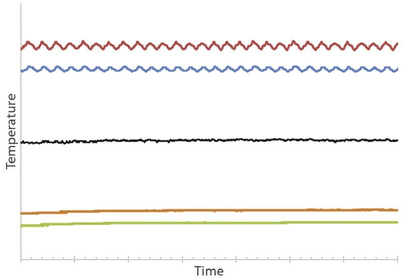
Figure 8. SAFEHX experimental data (red line – hot inlet temperature; blue line – hot outlet temperature; black line – buffer liquid temperature; orange line – cold liquid outlet temperature; green line – cold liquid inlet temperature).
Figure 9. Heat transfer for hot and cold fl uid (red line – hot fl uid heat transfer to the system; blue line – cold fl uid heat transfer from the system).
Performance
Using data from the sensors, it was possible to determine that the heat exchanger, operating at a volumetric fl owrate of approximately 1000 – 1200 litres/hr in the hot water loop, is capable of transferring approximately 4 kW. Figures 8 and 9 show temperature and heat transfer results. In the cold water loop, approximately 3 kW of heat was retrieved from the exchanger at a fl ow rate of 1000 – 1200 litres/hr. As a result of the absence of insulation, shell convection heat loss contributed to the difference between those two heat rates. Hot water loop temperature oscillations are caused by the on-off control of the hot water loop. In Table 2, the overall heat transfer coeffi cients calculated from prototype measured parameters are close to those calculated from numerical models. Further prototype improvements and different sets of operation conditions were already issued and, when just installing shell insulation, an increase of at least 15% on the overall heat transfer coeffi cient is expected. As a starting point of the technology, there is already a prototype with heat transfer performance for liquids compatible with commercial products and with all the safety and process control improvements already discussed.
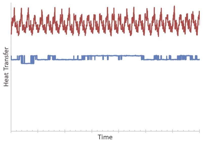
Table 2. SAFEHX preliminary test results Fluid pair Conditions Results
Cold side heat transfer coefficient 3 hours duration Inert fluid condensation to 500 to 1000 W/(m2.K)
warm cold water
Hot side heat transfer coefficient 3 hours duration Inert fluid evaporation to cool hot water 500 to 1000 W/(m2.K)
Overall heat transfer coefficient 3 hours duration Continuous evaporation and condensation of buffer fluid 250 to 500 W/(m2.K)
Conclusion
SAFEHX adds a substantial safety feature to existing or new sulfuric acid plants. The prototype achieved its original objective of safe heat transfer in a compact device. But it also benefi ts heat transfer operations with high fouling rates, operations where cold liquid temperature control is important, and for cases where process liquid loss is costly. The prototype is at an advanced stage and a commercial version of the product should be available in 2021.


