11 minute read
An Unfinished Chapter


Philip A. Henry, E2G | The Equity
Engineering Group, Inc., USA, examines ongoing efforts to update and improve the current industry codes and standards on pressure relief valve instability.
An An unfinished unfinished chapter chapter


The increased emphasis on safety in the ammonia and fertilizer industries has produced greater sophistication in the analysis of overpressure concerns. One area where this is particularly evident is in the study of the stability of pressure relief valves (PRVs) during activation. This affects all industries where PRVs are used to provide overpressure protection, including the ammonia and fertilizer industries.
The current guidance published in industry codes and standards is not sufficient to ensure that any company is fully protected from PRV instability issues. Limiting the inlet pressure losses to 3% of set pressure is a requirement laid out in ASME Section VIII, Appendix M that relates to preventing valve instability during an overpressure event.1 This 3% rule also appears in other industry standards, such as API 520 Part II and ISO 4126-9.2,3 However, the former states that limiting the inlet pressure drop to a specific value may not be the primary factor that guarantees PRV stability. PRV stability is an evolving issue, and there are additional factors that impact whether the valve operates in a stable manner.

Additional research is needed to fully understand all the parameters that affect PRV stability. Current flow testing programmes being conducted by the American Petroleum Institute (API) and the European Center of Safety Excellence (CSE) recognise the need to better understand the phenomena of PRV instability, with the goal of improving the guidance given to the PRV user community.
3% inlet pressure drop rule
The basic premise of the 3% rule is that during relief events, if the inlet pressure to the PRV fell below the blowdown pressure (or closing pressure) of the PRV due to high inlet pressure loss, the valve would close. Once the valve closes, static pressure at the inlet again builds rapidly and the valve re-opens. This repeats itself, often at high frequencies, and can produce chattering. Chattering creates serious vibrational disturbances, and can result in damage to the relief valve parts as well as possible failures of piping connections and loss of containment. For many years, limiting the inlet pressure loss to 3% of the set pressure was the only Recognized and Generally Accepted Good Engineering Practices (RAGAGEPs) guidance provided for designers to mitigate concerns regarding valve instability.
Experience and testing have shown that some PRV installations with inlet pressure losses greater than 3% have relieved and operated in a stable manner. Conversely, testing has shown that some PRVs may become unstable with inlet pressure drops that are less than 3% of set pressure. A joint industry project conducted by API demonstrated that there was no apparent correlation between valve stability and inlet pressure drop.4 Research is ongoing.

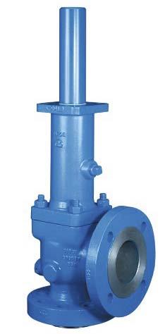
Figure 1. Crosby JOS spring-loaded PRV.

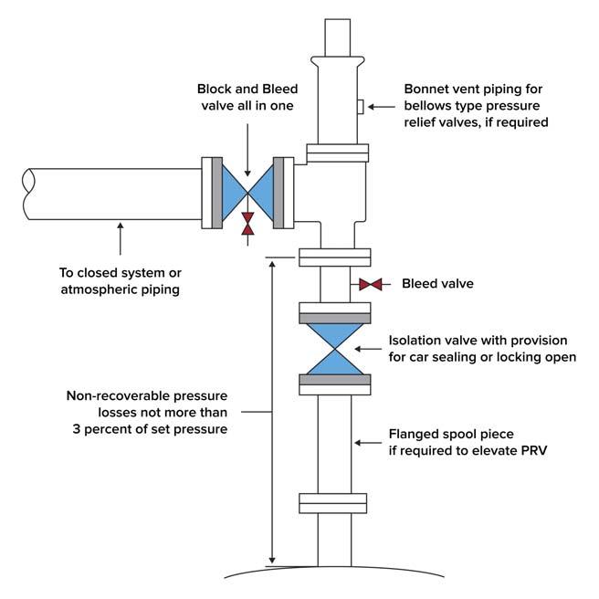
Figure 2. PRV installation showing 3% inlet loss criteria.
API historical guidance
API is the leader in the development of petroleum and petrochemical equipment engineering standards that provide proven, sound engineering and operating practices and safe, interchangeable equipment and materials. Many of its standards have been incorporated into US state and federal regulations and adopted by the International Organization for Standardization (ISO) for worldwide acceptance. The API Subcommittee on Pressure Relieving Systems (SPRS) produces several standards related to pressure relief systems, and these are used worldwide as the de facto RAGAGEPs for PRV design and installation. The API standard providing installation requirements for pressure relief devices is API 520 Part II. This standard has gone through many changes over the years, but only recently has the guidance related to PRV instability been appended to address some of the recent developments in understanding the phenomena.
From 1963 until March 2015, the only guidance provided to industry through the API SPRS standards concerning PRV instability was the 3% rule related to excessive pressure drop in the inlet piping to the PRV.
In 1994, the fourth edition of API 520 Part II was published, and it permitted owner-users to increase the allowable inlet pressure drop above the 3% criteria, provided an engineering analysis was completed. Modern relief valves provided by valve manufacturers have blowdowns in the range of 7 to 10% of set pressure, and the API SPRS determined that inlet losses up to 5% still gave a suitable safety margin between the inlet pressure loss and blowdown. Many operating companies were already accepting inlet losses above the 3% guidance for existing installations without experiencing any instability problems. Although no additional guidance was given as to what the engineering analysis should entail, conventional wisdom was that the engineer should work with the valve manufacturer to understand the blowdown characteristics
of the installed PRV, and assess the potential for valve instability with increased inlet losses.

API PERF results
In 1999, API initiated a joint industry project to further investigate PRV instability. This effort was conducted under the Petroleum Environmental Research Forum (PERF) and is generally referred to as PERF I.
The PERF I project was completed in 2013 and the results from this effort were mixed. Testing showed that, in many cases, PRVs did not chatter when inlet losses exceeded 3% of set pressure, while in some tests PRVs chattered when inlet pressure loss was less than 3%. Some PRVs even became unstable during closing. This was the first time that flow testing provided any indication that PRVs can become unstable upon closing. The industry has only concentrated on instability during opening because, once the valve is fully open, inlet losses become less of a concern, since the valve now has much more overpressure at the inlet to keep it open. This further supports the conclusion that the whole concept of valve instability is ever evolving.
One thing that became clear from the PERF I testing programme was that there was no real correlation between inlet pressure drop and valve instability. As stated in API 520 Part II: “Limited testing has shown that in many cases PRVs did not chatter when inlet losses exceeded 3% of set pressure while in some tests PRVs chattered when inlet pressure loss were less than 3%.”

API current guidance
Results of the PERF I research and more recent analytical approaches were used to enhance the current edition of API 520 Part II, which was published in 2020. In addition to providing more details on the engineering analysis required to exceed the 3% rule, additional information was given pertaining to the current state of the technology available for predicting PRV instability.
API 520 Part II describes several phenomena that can contribute to valve instability, including excessive PRV inlet pressure loss, excessive built-up back pressure, acoustic interaction, retrograde condensation, improper valve selection and oversized PRVs. It also makes it clear that there may be other phenomena not included in API 520 Part II that can lead to valve instability: “Research and experience show that PRV instability is complex and cannot be attributed to just one issue...There may be other phenomena that can lead to valve instability”.2
API 520 Part II now has guidance on performing an engineering analysis to check for PRV stability in applications where the 3% pressure drop criterion is not met. As conventional wisdom moves away from the 3% inlet pressure drop criterion, the engineering analysis should be performed for all new and existing installations.
API suggests that the engineering analysis should include the following tasks: Verify that the applicable flowrate is used in inlet and outlet pressure drop calculations. Verify valve sizing using corrected capacity based on inlet and outlet pressure drop.


We save energy and improve effi ciency.

To modernise existing production systems, Venti Oelde supplies fans equipped with special impellers offering the highest energy effi ciency and a reduced sound level. By optimising the infl ow and outfl ow as well as the regulation, Venti achieves considerable energy savings of up to 25 %.
Detailed system check Improved cost effectiveness High operational safety
High-tech fans made in Germany
Review available history to identify evidence of chatter. Perform a force balance assessment. Perform checks for acoustic interaction.
Overall, the goal of the API engineering analysis is to validate that the relief system installation has adequate relieving capacity and that it conforms to current design practice regarding relief valve stability.
A force balance method has also been developed that appears to have much more promise at predicting PRV instability than the 3% inlet loss rule. Whereas the 3% rule looks at the steady state conditions of fl ow through a PRV, the force balance method includes the dynamic effects of the pressure wave as it travels back and forth from the PRV. This technique was tested against the fl ow test data collected during the PERF I and found to have very promising results. API is developing a technical publication that will provide designers with example problems that show how to perform these calculations, but this has not been published yet.
The force balance is essentially a comparison between the forces acting to keep the valve open and the forces acting to close the valve. It is dependent on the PRV characteristics (opening time, blowdown, etc.), the speed of sound in the fl uid and pressure drops caused by the fl owing fl uid and pressure waves. It may be used both for conventional and balanced bellows spring-operated PRVs.
The API SPRS is moving away from steady state inlet pressure drop as the major contributor of PRV instability and is focusing more on dynamic effects, such as those addressed with the force balance and acoustic interaction methods. Annex C was added to API 520 Part II to address one form of instability caused by acoustic effects: acoustic interaction. The methodology presented in Annex C compares the acoustic frequency of the inlet piping to the opening and closing times of the PRV to establish a critical line length. Using this method, piping designers can show that the length of the inlet piping does not approach this critical line length, thereby avoiding resonant interaction between the piping and the PRV.

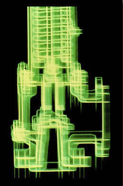
Figure 3. PRV instability.
Options to mitigate defi ciencies associated with the 3% inlet loss rule
API discussed several options in which the relief system designer has to mitigate defi ciencies identifi ed where inlet pressure drops are calculated to exceed 3% of set pressure.
The fi rst option to consider would be to complete the engineering analysis as defi ned in API 520. Making use of the force balance and acoustic interaction checks may eliminate any need to make costly physical modifi cations to the relief valve installation. Where the PRV has modulation tendencies – such as with modulating pilot-operated relief valves – using the required fl ow instead of the actual rated capacity of the valve can signifi cantly reduce the calculated inlet pressure drop. Some PRV manufacturers are willing to provide assurance in writing that their spring-loaded PRVs have modulating characteristics, in which case use of the required fl ow could certainly be justifi ed.
Physical modifi cations to the pressure relief installation may inevitably be required. Replacing the existing PRV with a modulating pilot, restricting the lift of the PRV or making use of remote sensed pilot valves are relatively simple modifi cations that can be made to mitigate an inlet pressure drop defi ciency. As a last resort, the inlet piping may need to be rerouted or increased in size to mitigate the situation.
Conclusion
This is an active area of research, and updates to the guidance given in API 520 are expected to change periodically as more research is completed and knowledge is gained. It is expected that, in the near future, API guidance will continue to move away from an inlet pressure drop criteria towards methods that address the dynamic effects of PRV operation.
References
1. American Society of Mechanical Engineers, ‘Boiler and Pressure
Vessel Code, Section VIII, Division I, Rules for the Construction of Pressure Vessels’ (2019). 2. American Petroleum Institute, ‘API Standard 520, Sizing,
Selection, and Installation of Pressure-Relieving Devices, Part II –
Installation’, 7th edition (2020). 3. ISO 4126-9, ‘Safety devices for protection against excessive pressure – Part 9: Application and installation of safety devices excluding stand-alone bursting disc safety devices’, DIN
Deutsches Institut für Normung e. V. (2008). 4. ALDEEB, A., DARBY, R., and ARNDT, S., ‘The dynamic response of pressure relief valves in vapor or gas service. Part II: Experimental investigation’, Journal of Loss Prevention in the Process Industries,
Vol. 31 (September 2014), pp. 127 – 132.


