8 minute read
A Welcome Adaptation
A WELCOME A WELCOME ADAPTATION ADAPTATION

Gordon Woolf and Jose R. Ferrer, Tecnicas
Reunidas Group, Spain, consider how the design of heat exchangers for use in nitric acid units can be adapted to realise energy savings.

It is well known that nitric acid plants are powered by means of ammonia combustion with nitric acid production. The self-generated power of the typical dual nitric acid plant reduces the overall energy consumption. However, with increasing focus on the worldwide energy transition, maximising the utilisation of energy resources other than fossils fuels is taking on even greater relevance for plant owners. The perceived trend in the coming decade is that there will be an increase in ammonia production from hydrogen coming from water electrolysis – using zero carbon electricity from renewable sources, such as solar panels and wind turbines, or even from natural gas with full carbon capture. The energy produced from this ammonia in a nitric acid plant would be sustainable: a welcome adaptation for future generations.


Nitric acid unit heat exchangers
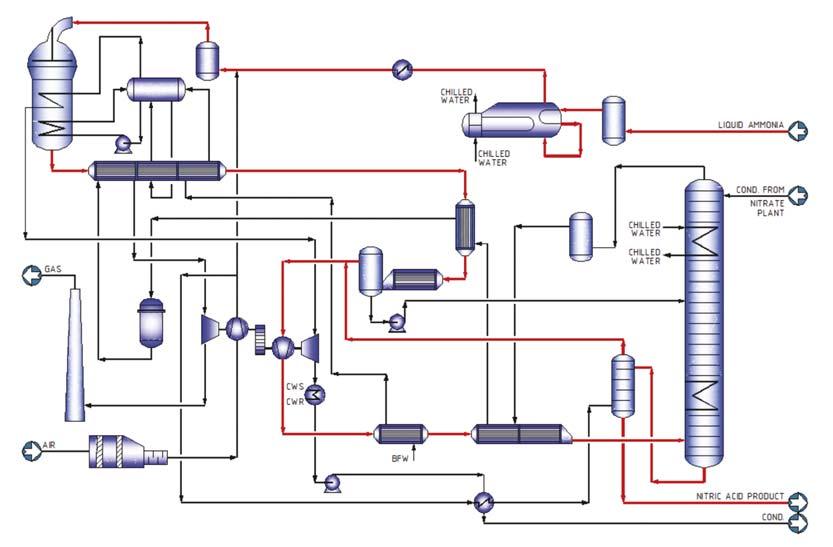
Looking at a typical dual process nitric acid unit designed by ESPINDESA (the branch of Tecnicas Reunidas specialising in fertilizer technologies) approximately 30% of the main equipment present in the unit are process heat exchangers (Figure 1). With regards to energy, for a typical dual nitric acid process where the total pressure drop in the system is in the range of 1.5 – 1.7 bar (depending on the absorption tower design), approximately half of the overall unit pressure drop is generated in the heat exchangers. It is therefore obvious that any reduction in pressure drop through those heat exchangers, via an optimised design, will translate into energy savings and,
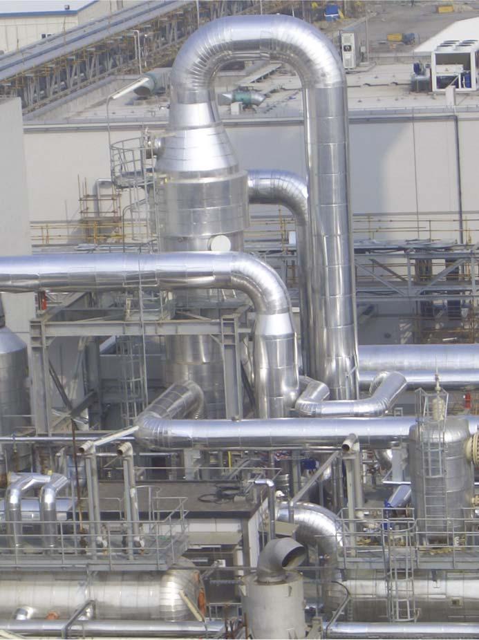
consequently, substantial operational cost savings. This needs to be balanced whilst considering a unit’s CAPEX, especially in the low-pressure section which operates at approximately 4 barg and normally features equipment with a larger diameter to achieve the pressure requirements. Here, any design that helps to minimise the size of the equipment will signifi cantly infl uence the overall investment cost. One of the company’s heat exchanger designs is the DDS exchanger (Figures 2 and 3), which was originally developed by Tecnicas Reunidas’ heat transfer division for nitric acid exchanger trains (in collaboration with ESPINDESA) and power generation applications, specifi cally for nuclear power plant safety cooling systems. Figure 1. Simplified process flow diagram of a nitric acid dual pressure unit. Its key characteristic is the achievement of low shell side pressure drop for high fl owrates, whilst maintaining a shell side heat exchanger coeffi cient that enhances its performance and heat transfer. Even though the exchanger’s design concept is primarily intended for applications in new build plants, it is also particularly of use during revampings or re-rating applications. In both cases, the design can be tailored to meet the specifi c needs of various processes and plants. Additionally, the mechanical design is adaptable to and compliant with all major international codes, such as TEMA, ASME, GOST and PED. The system is a variation of the TEMA triple segmented baffl e, in which – due to the special DDS baffl e confi guration – the main process stream crossing the shell is divided into several streams in parallel, with the following advantages: The cross flow velocity of the shell side fluid through the bundle is reduced, as is the length of each shellpass between baffles. Consequently, the pressure drop can be up to 30 times less when compared against a conventional single segmental baffle for the same baffle distance. The design minimises vibration problems, as the distance between baffles can be reduced while maintaining low-pressure drop. This minimises the tube’s unsupported length or span, contributing to a design that is robust in the face of fluid-induced vibration. The configuration combines cross flow (perpendicular to the bundle) with longitudinal flow (parallel to the tubes), both of which contribute to and enhance heat transfer coefficient. The design permits the development of very compact designs, while maintaining acceptable pressure drop limits. Figure 2. Vertical DDS unit in nitric acid plant. It is therefore well suited for gas systems with high gas fl ows and liquid systems with large volumetric fl ows. In both instances absorbed power (for compressors and/or pumps) can be reduced, improving operational cost.
Design constraints
When considering design constraints for a new plant, low-pressure drop on its own can be resolved in a number of ways by an able designer. Increasing the size of the equipment – i.e. a larger tube pitch, tube outer diameter (OD) or larger shell diameter – is the most common solution for standard exchangers. The key is to fi nd the right balance between the constraints of pressure drop, exchanger duty and cost. However, a larger diameter leads to large shells and increased

tubesheet thickness, while an increased number of tubes (yielding a higher exchange area) leads to a larger installed weight; together, these all lead to a higher investment cost.
As part of the plant design constraints, the particularities of the nitric acid process must also be taken into account, and specifi cally the acidic condensation phenomenon that occurs during normal operation and particularly during start-up and shutdown procedures. The acceptable temperature profi les and manufacturing material selections are limited and metallurgical experience is critical for nitric acid units. During material selection, an equilibrium is sought for each heat exchanger – based on their individual or specifi c service within the whole system – by using different specialised grades of steel, titanium and/or zirconium materials, depending on the specifi c temperature, pressure and acidic conditions.
It is also critical to study different exchanger confi gurations to minimise constraints imposed by piping design, and consider different options for heat exchangers in vertical-horizontal or interconnection between heat exchangers.
Therefore, as pressure drop is often a key design factor in industrial plants, the ability to design for lower pressure loss – without necessarily increasing length and diameter – provides clear cost benefi ts. This is particularly of interest for gas applications, owing to compression costs. However, there are other advantages that can be obtained, depending on the confi guration required for the client’s operation.
Reduced operating costs
By utilising a heat exchanger design that features lower pressure losses, the power required to move fl uids through the system is thereby reduced. The pump/compressor will therefore draw lower amperages, resulting in lower operational expenditure. This technology is highly recommended in gas plants for reducing compressor size.
Saving space
Implementing a heat exchanger design with the same pressure loss as an existing system, but with smaller exterior dimensions, yields an overall reduction in outer shell diameter and thickness. This can be of benefi t in an existing plant, where conforming to space restrictions when substituting an exchanger unit is critical and the reduced envelope and weight can make the installation process easier without sacrifi cing process capacity. Other potential benefi ts might include improved access or maintenance space in older congested plants, or a reduction in installed weight in existing structures where weight limitations need to be observed.
Increased capacity
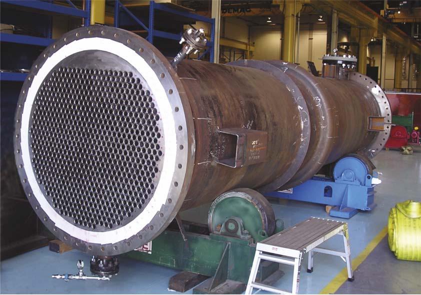
Figure 3. DDS exchanger during SS hydrotest. By producing a heat exchanger design with the same exterior dimensions, yet capable of higher fl ow rates for a similar pressure loss, an increased capacity is achieved. This is especially advantageous for revamped or upgraded plants where power consumption, space or other existing limitations need to be considered, such as an existing nuclear power plant where key exchangers are the emergency cooling systems. These units are installed in areas which – due to radiation protection, seismic and other specifi c conditions of such plants – are basically concrete bunkers, where the option to expand or modify the available space is out of the question.
When plants of this type undergo a re-rating to increase their capacity, the exchangers can be required to process larger fl ows of cooling water; thus a solution that meets the new capacity with the existing or near to existing dimensions is required.
The company’s DDS baffl e arrangement is specifi cally developed to permit a lower pressure resistance for large fl owrates. This design is based on fundamental engineering principles and complies with the code requirements for heat exchangers. The calculation formulas, together with design methodology, are incorporated into proprietary software that has been developed and refi ned – based on empirical data gathered over more than 30 years – to achieve a repeatable, fully validated design method that has been proven in installations worldwide.
The low-pressure DDS baffl e arrangement is, as mentioned, essentially a multi-segmental baffl e and a variation on existing TEMA standards. It is, therefore, suffi ciently similar to standard single or double segmental designs that it benefi ts from well-proven fabrication and installation procedures, requiring no additional or specialist tooling (unlike other high fl ow baffl e technologies). Consequently, the equipment can be fabricated at standard workshop rates almost anywhere in the world.
Conclusion
Whether the objective is to optimise the initial design of a new plant from the outset or upgrade an existing plant within tight constraints, both investment and energy cost savings are always major factors. The ability to balance the right combination of these costs versus other key factors – such as space, weight, capacity and so on – is therefore highly benefi cial to the end user, as is selecting the ideal combination that best adapts to the application and unique conditions of the fi nal plant location.


