15 minute read
Drone geophysics: developing guidelines for international best practice


Tim Archer1* summarises work released by the Near-Surface Geophysics Inter-Society Committee on UAV Geophysics Guidelines.
Introduction
Advertisement
This paper is offered following EAGE’s kind invitation to provide a full-paper version of a keynote presentation given by the author at the EAGE’s 3rd Conference on Airborne, Drone and Robotic Geophysics, which was held in Belgrade in September 2022.
It summarises work completed and released by the Near-Surface Geophysics Inter-Society Committee on UAV Geophysics Guidelines, providing guidance to date for drone magnetic surveys, but in future for other geophysical techniques as well. The overarching aim of this committee is to encourage and support high-quality drone geophysical data acquisition on an international basis.
Note that the terms ‘drone’ and ‘UAV’ (Unmanned Aerial Vehicle) are used interchangeably throughout this review paper.
International committee
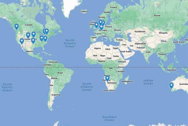
The work summarised in this paper was prepared by an international committee (Figure 1 and Table 1), currently chaired by Mr Geoff Pettifer and Mr Ron Bell, that was convened after the inaugural meeting of the Summit on Drone Geophysics (November 2020).
The committee perceived a need to distribute best practice guidelines to a burgeoning but sometimes ill-informed drone geophysical survey community, for the following reasons (committee presentation, Nov 2021):
• All drone geophysics operators/contractors (geoscience-trained and ‘lay; personnel) need to understand the basics of good drone geophysics data acquisition, noise mitigation and data reduction and processing. All new players are on a steep learning curve
• Drone geophysics comes with different learning challenges for geoscientists with a background in either ground or airborne geophysics
• Bad data gives our industry and profession a bad [reputation]
• Bad safety and incidents by rogue operators may result in restrictions on the operations of responsible operators, that we don’t need
• We need to protect clients and enable multi-use of data beyond original purposes
• We need experienced operators to share their wisdom and knowledge of good practice to help bring all operators up to speed quicker
The following sub-committees were accordingly set up in March 2021: Magnetics, Radiometrics, Electromagnetics, Gravity, Survey planning and execution, Positioning, Drone mapping, Safety, Drone platforms. It rapidly became clear, however, that the task facing these pro bono sub-committees was a huge one, complicated substantially by the fact that many of the technologies listed were still in their infancy as far as drone-based deployment was concerned. The committee therefore decided to focus initially on drone magnetic surveys, arguably the most developed and most popular application then available, with other guideline documents to follow.
Drone magnetic survey guidelines
After much online discussion and several draft documents, ‘UAV Total and Vector Field Magnetics Surveying Guidelines (Version 1)’ was formally released on 12 November 2022, via a public webinar hosted by the Society for Exploration Geophysicists. The document (for which the chapter headings are provided in Table 2) is now available for free download at www.guidelinesfordronegeophysics.com/, and forms the basis for much of the technical material which follows.
1 Reid Geophysics
* Corresponding author, E-mail: tim@reid-geophys.co.uk
DOI: 10.3997/1365-2397.fb2023060
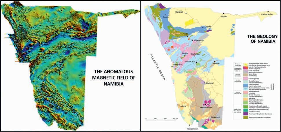
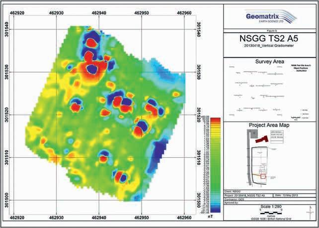
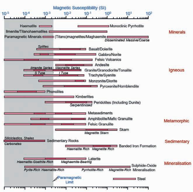
Magnetic survey in general enables rapid and cost-effective mapping of buried geological and anthropogenic features, from the regional scale and larger (Figure 2a) to the site scale and smaller (Figure 2b). This mapping relies on variations in magnetic susceptibility, for which indicative values are provided in Figure 3.
Within this review paper, it is not our intention to regurgitate the entire drone magnetic guidelines referenced above. Rather, we focus on key elements of the work completed, with particular emphasis on features specific to drone-based surveys that differ from those encountered during more conventional magnetic data collection.
Survey types
The guidelines describe three broad types of drone magnetic survey, summarised in Table 3 and differentiated by both sensor elevation and exploration target:
Most readers will be more familiar with one or more of these survey types than with the others. The important general observation is that survey parameters should be selected to match the required exploration objectives.
System configuration
The guidelines provide checklists pertaining to the technical, logistical, and regulatory factors relevant to optimally configuring a new UAV magnetics system or improving the performance of an existing system.
Guidance is also provided on planning an actual survey, and on equipment required for daily field operations.
Survey safety and regulations
Extensive treatment is given of the safety and regulatory requirements pertaining to drone-based geophysical surveys in general. Practical aspects of safely flying a drone with a magnetic sensor payload based on three different survey altitude categories are discussed, with specific reference to obstacle avoidance risks, navigation risks, and drone communication risks.
Name Organization Society Affiliations
Tim Archer Reid Geophysics
Chase Attwood SkySkopes, Inc.
EAGE, SEG, PESGB
Elizabeth Baranyi Seequent SEG, AGU
Ron Bell IGS, LLC SEG
Ed Cunion Red Rocks Geophysics
SEG, KEGS
Alexey Dobrovolskiy SHP Engineering EAGE
Irina Filina U Nebraska Lincoln SEG, AGU, AAPG
Jan Francke Ground Radar APEGA
Jeff Gamey Tetra Tech EEGS
Bruno Gavazzi Enerex SEG, EGU
Rob Harris Geonics SEG, EEGS, KEGS
James Jensen Southern Geoscience Consultants ASEG, SEG
Bob Lawson Geophex Pty Ltd
Jean Legault Geotech Airborne SEG, EEGS, EAGE, ASEG, SAGA
Leslie McChesney Southpac Aerospace IAGSA, ISASI, ASASI, WIA
Paul Mutton Touchstone Geophysics ASEG, AIG
Geoff Pettifer GHD / Terra Entheos Geoscience EEGS, SEG, EAGE, ASEG, KEGS, IAH, AEG
Johannes Stoll Mobile Geophysical Techcnologies GmbH SEG, EAGE, DGG
Steven van der Veeke Medusa Radiometrics / U Groningen EAGE
Rainer Wackerle GeoIntrepid Namibia / Intrepid Geophysics
Callum Walter Queens U SEG, AGU
Dennis Woods Discovery international IAGSA
Chapter Title
1 Introduction
2 Magnetics basics
3 Magnetic survey types
4 Configuring a UAV magnetics system
5 UAV magnetics surveying safety and regulations
6 Positioning and mapping
7 Survey planning and preparation
8 Magnetic survey noise sources
9 Survey acquisition and QA/QC
10 Compensation and calibration
11 Processing airborne and UAV magnetics data
12 Imaging UAV magnetics data
13 Interpretation of UAV magnetics data
14 Conclusions and recommendations
15 References and bibliography
The guidance then addresses regulatory aspects and safety planning within a risk assessment safety approach, not dissimilar to other geophysical and general job safety operational health and safety planning approaches. The regulatory aspects and safety planning information is based on ICAO and industry standards such as the Flight Safety Foundation Basic Aviation Safety (BARS) program (flightsafety.org/basic-aviation-risk-standard/). As such these standards are recognised by most international member states and form a framework for operations. These guidelines do not, however, replace the regulatory requirements within the country of survey operation.
Spatial positioning
As with any geophysical data acquisition, spatial accuracy of the drone-based survey measurements is of paramount importance. Guidance is provided on the relative merits of Real Time Kinematic (RTK), Post-Processed Kinematic (PPK), Inertial Measurement Unit (IMU) and other positioning options.
The importance of using accurate altimetry and terrain models during survey planning and survey execution is also emphasised.
When operating in steep or poorly-mapped terrain, it may be necessary to acquire an accurate terrain surface prior to the main geophysical survey, using a smaller drone equipped with a photogrammetric quality camera, and possibly a LiDAR unit as well. The operation and data processing and quality considerations of photogrammetric and LiDAR surveying also requires use of high-accuracy RTK surveying capability with an antenna base station, radio link and a rover antenna on the drone.
Survey planning
Before survey planning can even get underway, the first important task is to ensure the survey specifications are in order and fit-for-purpose, regardless of whether the drone magnetic survey will be carried out in-house or by a contractor. Good communications between the person who wrote the specifications, the survey geophysicist, the drone pilot and the client is essential to plan the survey well and to meet the objectives and client expectations.
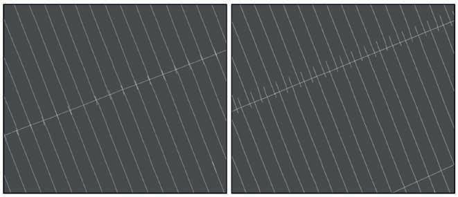
To achieve this, the creation of a master survey plan is strongly recommended. The master plan is to be used as a template for the individual tiles, even in cases when adjustments have to be made ad hoc in the field due to unforeseen circumstances. The planning software will have to be able to align the daily flight plan to the master plan. Figure 4 compares a perfectly flown tile boundary (left) with a badly flown one (right). Although the boundary of the survey shown on the right will not give levelling problems because of the well-placed tie line, it will give problems when gridding the data.
All surveys should further be planned slightly larger than the actual survey area, preferably with a buffer of one to three times the nominal line spacing. Turns should start outside the buffer zone in order to avoid manoeuvre-induced noise in the production data. It is further advised to fly smooth U-shaped turns instead of a ‘box’; the smoother the turn, the lower the possibility of picking up manoeuvre noise at line ends, especially when the sensor is suspended below the platform. All excess data will eventually be cut for the final deliverables.
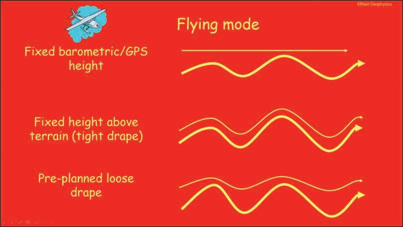
Drone-borne magnetic surveys may be flown at fixed barometric/GPS height, at fixed height above terrain (which is always approximate, due to safety and operational considerations), or on a pre-planned loose drape. These differences are illustrated in Figure 5. Each choice has its own advantages and disadvantages. For magnetic surveys it is important to fly neighbouring lines and traverses and ties at the same altitude. The reason for this is that variations in ground clearance, e.g., different distances to the magnetic sources, can significantly change the amplitude of the measured signal.
The absolute accuracy of the ground clearance that needs to be adhered to depends on the nominal ground clearance. The magnetic signal of a dipole falls off with the cube root of the distance between sensor and source. Hence, at an ultra-low ground clearance of a few metres, centimetre inaccuracies in the ground clearance can matter.
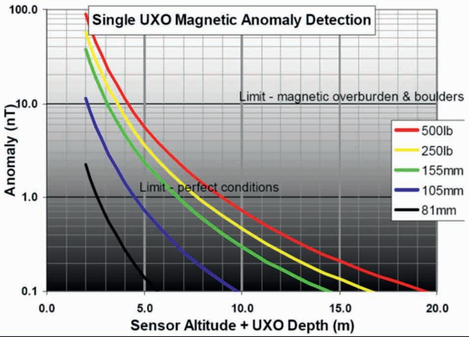
The above point is well illustrated by the UXO example presented in Figure 6. Small inaccuracies in the determination of flight height at levels below 5 m above ground result in considerable variations of the flux density. In order to map the magnetic field of a small metal object buried in the ground, altitude accuracies in the order of 10 cm and better are desirable.
Reid (1980) showed that the total magnetic field is sampled sufficiently when flying at a line separation of twice the ground clearance. When gradients are measured the line separation should be equal to the ground clearance. Thus, the optimal line separation for a drone magnetic survey is controlled by the achievable/practical average terrain clearance (see Table 3 above).
Noise sources
Drone magnetic data contain noise from various sources. The guidelines deal individually with instrument noise, manoeuvre noise, electromagnetic interference, and survey artefacts.
Instrument noise originates from electronic equipment installed in the drone, moving parts in the platform engines and eddy currents induced in any electrical conductor moving through the ambient magnetic field.
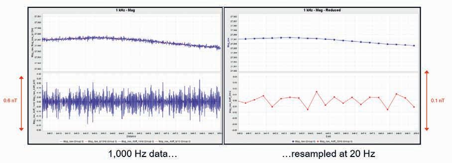
It is usually assessed using a differencing algorithm such as the normalised fourth difference (N4D). Because of the high sampling rates typically associated with drone magnetic data acquisition, however, such data usually need to be sub-sampled to provide meaningful instrument noise comparisons with conventional magnetic data. This point is illustrated in Figure 7.
Manoeuvre noise can be defined as all magnetic disturbances or inaccuracies that are caused by directional sensitivity of the employed sensor and/or attitude changes of the moving platform-sensor system.
There are two types of manoeuvre noise: the first is caused by the sensor itself when the recorded magnetic data change with the orientation of the sensor towards the ambient magnetic field, which is often referred to as ‘Heading Error’. The second type is caused by attitude changes of the platform producing magnetic disturbances of varying magnitudes at the sensor position. Both types occur with rigidly mounted sensors as well as with suspended sensors and can reach magnitudes of 5 nT or more.
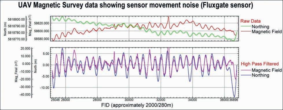
Strong attitude changes of the sensor-platform system can be caused by changes in survey speed, harsh movements of the platform (usually over steep terrain or to avoid obstacles) and obviously by wind.
Figure 8 depicts drone magnetic data flown in an easterly direction under very windy conditions; hence the variations in the north position are a good indicator of the swing of the bird. The recorded magnetic data and the north position are shown in the top panel and their high-pass filtered version in the bottom. As can be seen there is a very good correlation between the magnetic signal and the bird swing.
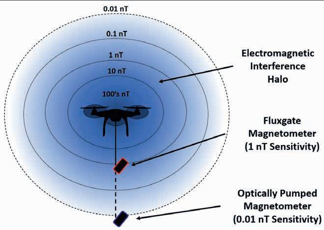
Electromagnetic interference: This complex topic has been addressed by numerous authors, many of whom are cited in the guidelines. These electromagnetic interference signals can be divided into two dominant types based on their wavelength and overall effect within the gathered magnetic data. These two types consist of static and dynamic electromagnetic interference signals. Static interference is a non-oscillating magnetic field signal that results in a permanent or relatively long wavelength offset within the gathered magnetic data. These static interference signals can result from permanent and induced magnetisation of ferrous components within the airframe (eg, the permanent magnets in the electromagnetic motors) and DC currents within power supply wires. In contrast, dynamic electromagnetic interference is an oscillating signal of varying frequencies that can be caused by the rotation of the electromagnetic motors, DC and AC current fluctuations, and secondary eddy current fluctuations.
Figure 9 presents a (highly simplified) diagram of the electromagnetic halo surrounding a multi-rotor drone in flight.
Artefacts are much more difficult to detect than noise in drone magnetic data, because of their systematic nature. Artefacts are caused by badly executed survey operations, such as bad line keeping, or by processing errors, especially in the tie line levelling step. As explained in the guidelines, line overlaps, line levelling, tile offsets, and tile boundaries can all produce unwanted survey artefacts, unless care is taken to minimise these effects.
Data QC
Whether carrying out or supervising a drone magnetic survey or writing a specification for a drone magnetic survey acquisition process, it is important to have a way to ascertain under field conditions at the time of the survey, the total system noise of the UAV/magnetometer system carrying out the survey.
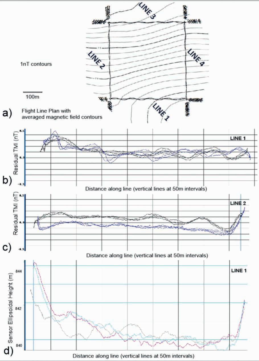
The guidelines recommend a simple test to establish the real-world system noise of a UAV-based magnetic survey using repeatability as a means for determining system quality. Such a test is primarily a quick way that clients can independently assess the noise levels of the magnetic survey system and the drone performance. Repeatability tests are non-commercial so they could be published by drone operators to demonstrate the repeatability (noise level) of their system(s) and/or they could be requested by clients to be performed prior to a survey operation. The test flight should not take more than 20 minutes to fly and should be repeated in case of changes to the platform-sensor system as well as significant changes in environmental conditions.
Repeatability flights measure the ‘real world system noise’ across a broad spectrum of wavelengths and by analysing the deviation from the mean the flights do not need to be at very high altitude or in very quiet areas. Flying a 400m x 400m box flight pattern six times (three clockwise and three anticlockwise) has been shown to be effective (Mutton, 2021) and only takes about 15 to 20 minutes to complete. Ideally such a dataset can be made prior to awarding a contract (to demonstrate noise levels and data formats), prior to flying (to confirm system noise levels in local conditions), and during a survey if there is a substantial increase in the wind or any change to the system. The latter may be needed for clients to understand the effect of wind so that standby may be justified. Diurnally corrected noise levels at 1SD (one sigma deviation), 2SD, and 3SD can at least can be used to quantify system noise levels and be compared to contractual requirements. Note that the test data needs to be diurnally and IGRF corrected. Critically, the data sampling frequency for tests must be specified and provided with required errors. Rapid sampling (e.g., 500 Hz) can greatly increase apparent noise levels when compared with lower sampling rate (e.g., 10 Hz) systems (see Figure 7 above).
Figure 10 shows the results from such a repeatability test. The top panel (a) indicates the line path, the middle panels (b) and (c) show the deviation from the average for Lines 1 and 2 (Y-axis:
± 0.5 nT) and the bottom panel shows the variation in height for Line 1 (Y-axis: 1 m).
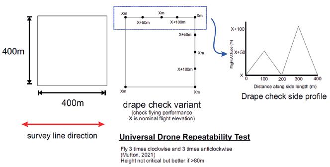
In a variation of the Figure 10 test which is flown on a plane, an improved flight to better test the drone and draping algorithm performance is shown in Figure 11. In the Figure 11 variant, artificial terrain is added on two of the legs that represent very steep topography as might be expected in the survey area.
Note that the repeatability tests depicted in Figure 10 and Figure 11 are not yet established as a universal standard procedure. In some surveys the size of the box flown may need to be varied for different applications, e.g., the test box to be flown for a UXO detection or archaeological survey at 1 m line spacing may have to be much smaller than the box for a geological mapping survey at 50 m line spacing.
In order to establish the universality of the tests, one will need a series of such tests performed by different platform-sensor systems under varying environmental conditions to determine the best proactive noise levels at a standard (e.g., 10 Hz) sampling rate. Once established, any of the magnetic signal sigma deviations could serve as a contractual threshold similar to the Figure of Merit (FOM) established for conventional (manned) airborne magnetic surveys. Height variations can similarly be defined in a standardised test.
Suggested technical specifications, QA/QC considerations, and product deliverables for commercial drone magnetic surveys are also presented in the published guidelines.
Compensation and calibration
There are two common types of magnetic sensor used in airborne geophysics: total field magnetometers and fluxgate vector sensors. Whereas the noise or inaccuracies of optically pumped total field magnetometers is far below any noise threshold required for aeromagnetic surveys, fluxgate magnetometers used in vector sensors have certain characteristics that require special attention in order to produce reliable data. The compensation/calibration of both sensor types is therefore discussed separately in the published guidelines.
Manoeuvre noise (discussed above) is currently the biggest obstacle for drone-based surveys to achieve the quality of conventional aeromagnetic data. Many drone operators do not have access to compensation or calibration software and there are only a very few commercial versions available. Further, compensation only works well for systems with rigidly mounted sensors and the limited payload of (most) drones prevent long suspension distances to attenuate platform influences sufficiently.
The conventional compensation strategy is not, or is only partially, applicable to drone-based systems due to a variety of reasons:
• The required ‘magnetically quiet environment’ by simply flying at high altitudes cannot be achieved by drones.
• Fixed-wing UAVs are theoretically able to fly the required manoeuvres of ±10° pitches and ±5° rolls and yaws. It is, however, questionable whether these can be programmed into the navigation software.
• Rotary wing UAVs (copters) are capable of much larger attitudes (Euler angles) and large pitch and yaw angles can and do occur during production. So far nobody has proven that Leliak’s equations are suitable to compensate such large-angle manoeuvres.
• Copter UAVs with a suspended sensor are the most frequently used systems for drone-based magnetic surveys. Any compensation algorithm for such systems therefore has to compensate not only for the manoeuvres of the entire platform-sensor system, but also for the sensor motion with regard to the platform. No algorithms have yet been developed for this task and it is highly questionable whether the accuracy of the GPS receivers in both platform and sensor, is sufficient to accurately calculate the position of the sensor within the coordinate frame of the platform.
• Further, smaller drones are not capable of supporting a highdrag bird which would stabilise the bird’s position. To achieve some stability the sensor is mounted either on four cables (Geometrics) or on a semi-rigid hose pipe (GEM).
• It should also be noted that the manoeuvrability of a copter drone is much higher than that of a fixed-wing platform.
However, this manoeuvrability can result in pendulum motion of the sensor from sudden changes in speed or direction
The authors of the published guidelines are aware of very promising research activities in the related fields of drone magnetic data compensation and drone magnetic system calibration, but none of these initiatives have yet reached a final or generally approved status.
Data processing, imaging, and interpretation
Much of the data processing, imaging and interpretation applied to drone magnetic data is similar to that applied to other magnetic data streams, so will not be presented here. All of these topics are, however, discussed in detail within the published guidelines, for the benefit of those readers who lack this prior (non-drone) experience.
In addition to the very important drone peculiarities of compensation and calibration summarised in the previous section, it is worth bearing in mind that drone-based magnetic surveys potentially offer huge improvements in spatial resolution relative to other variants, due to a combination of (a) rapid sampling (b) low clearance and (c) arbitrarily close line spacing.
Future initiatives
The work of the Near-Surface Geophysics Inter-Society Committee on UAV Geophysics Guidelines continues, with upcoming initiatives likely to include an update of the drone magnetic survey guidelines, and the initial release of corresponding guidelines for drone-based gamma ray spectrometry, frequency domain EM, time domain EM, and GPR surveys.
Conclusion
Drone technology is here, and is hugely useful in a range of geophysical applications, including the relatively inexpensive, far safer, and extremely high-resolution magnetic surveys discussed in the recently published international guidelines that are summarised in this review paper.
The committee responsible for these guidelines is always looking for new members and new insights to improve existing and future publications. Readers are encouraged to join the international drone geophysics conversation by:


Visiting the committee website (www.guidelinesfordronegeophysics.com/)
Joining the EAGE UAV LinkedIn Group (www.linkedin.com/ groups/9183151/)
Attending the next SEG Summit On Drone Geophysics, which takes place online on 23-26 October, 2023 (seg.org/ calendar_events/2023-summit-on-drone-geophysics/).
Acknowledgements
A huge thank you to all of the committee members who contributed to the drone magnetic survey guidelines launched in November 2022, and whose work I have reproduced, sometimes verbatim and sometimes reworked for clarity and accuracy, within this review paper.
References
A more complete list of drone-based geophysics articles and references is provided in the published guidelines).
Dentith, M. and Mudge, S. [2014]. Geophysics for the Mineral Exploration Geoscientist. Cambridge University Press. 438 pp.
Mutton, P. and Domanin, A. [2021]. A Universal Drone Magnetic Survey System Noise Measurement Test. SEG-NSG 2021 Summit on Drone Geophysics, Extended Abstract
Reid, A.B. [1980], Short Note: Aeromagnetic Survey Design. Geophysics 15(5), 973-976.


